1
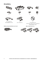
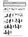
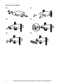
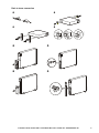
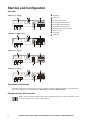
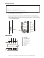
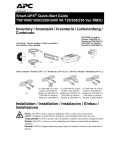
Installation Guide Smart-UPS™ X
Tower/Rack-Mount 2U 2000/2200/3000 VA
Important Safety Messages
Read the instructions carefully to become familiar with the equipment before trying to install, operate, service or
maintain it. The following special messages may appear throughout this manual or on the equipment to warn of
potential hazards or to call attention to information that clarifies or simplifies a procedure.
The addition of this symbol to a Caution product safety label indicates that an electrical hazard exists
which will result in personal injury if the instructions are not followed.
The following safety messages may appear throughout this manual to warn of potential
hazards.
CAUTION
CAUTION indicates a potentially hazardous situation which, if not avoided, can result in equipment damage and minor or
moderate injury.
CAUTION
CAUTION indicates a potentially hazardous situation which, if not avoided, can result in equipment damage.
Safety and General Information
Inspect the package contents upon receipt. Notify the carrier and dealer if there is any damage.
Read the Safety Guide supplied with this unit before installing the UPS.
• Adhere to all local and national electrical codes.
• This UPS is intended for indoor use only.
• Do not operate this UPS in direct sunlight, in contact with fluids, or where there is excessive dust or humidity.
• Be sure the air vents on the UPS are not blocked. Allow adequate space for proper ventilation.
• The battery typically lasts for two to five years. Environmental factors impact battery life. Elevated ambient
temperatures, poor quality utility power, and frequent short duration discharges will shorten battery life.
• Connect the UPS power cable directly to a wall outlet. Do not use surge protectors or extension cords.
• The batteries are heavy. Remove the batteries prior to installing the UPS in a rack.
• Always install external battery packs (XLBPs) at the bottom of the rack. The UPS must be installed above the
XLBPs.
• The UPS display interface will recognize as many as 10 external battery packs connected to the UPS.
However there is no limit to the number of XLBPs that can be used with the UPS.
su0434a
Inventory
(4)
(4)
Not included with
SMX3000RMJ2U model
(2)
230 V models only
(2)
(2)
1 Documentation CD
1 PowerChute software CD not included with
SMX3000RMJ2U model
High voltage models only
gen0744a
Models with preinstalled network cards
(6)
2
Installation Guide Smart-UPS X Tower/Rack-Mount 2U 100-240 Vac 2000/2200/3000 VA
Installation
Remove the battery
CAUTION
DAMAGE TO EQUIPMENT OR PERSONNEL
• The equipment is heavy. Always practice safe lifting techniques adequate for the weight of the equipment.
• Remove the battery before installing the UPS in a rack.
Failure to follow these instructions can result in equipment damage and minor or moderate injury
Use the battery handle to pull the battery out of the unit.
3
su0477b
su0474b
2
su0473b
1
Four post rack installation
Use the APC Four Post Rail Kit (supplied).
2
su0440a
su0552a
1
4
su0559a
su0469a
3
su0479a
6
su0478a
5
su0563a
7
Installation Guide Smart-UPS X Tower/Rack-Mount 2U 100-240 Vac 2000/2200/3000 VA
3
Two post rack installation
2
su0471a
su0470a
1
4
4
su0472a
6
su0562a
5
su0560a
su0561a
3
Installation Guide Smart-UPS X Tower/Rack-Mount 2U 100-240 Vac 2000/2200/3000 VA
Rack to tower conversion
2
3
4
su0554a
su0583a
su0555a
1
6
su0557a
su0558a
5
Installation Guide Smart-UPS X Tower/Rack-Mount 2U 100-240 Vac 2000/2200/3000 VA
su0564a
8
su0556a
7
5
Start-Up and Configuration
Overview
su0492a
2000 VA Low Voltage
SmartSlot
UPS input
Chassis ground screw
Controllable Outlet Group 1
Controllable Outlet Group 2
Controllable Outlet Group 3
External battery pack connector
EPO connector
Serial port
USB port
su0493a
2200/3000 VA High Voltage
1
2
3
4
5
6
7
8
9
:
su0494a
2200 VA Low Voltage
su0495a
3000 VA Low Voltage
Controllable outlet groups
The outlets on the UPS are configured into groups. To configure the controlled outlet features, use the Advanced
menus on the display interface and navigate to: Main Menu > Control > Outlet1 Control.
Emergency Power Off Connection
Refer to the user manual included on the CD that is supplied with the unit for more information on how
to connect the Emergency Power Off (EPO) Switch.
6
Installation Guide Smart-UPS X Tower/Rack-Mount 2U 100-240 Vac 2000/2200/3000 VA
Electrical connections
CAUTION
RISK OF EQUIPMENT DAMAGE
• Adhere to all local and national electrical codes.
• Wiring should be performed by qualified electrician.
• Always connect the UPS to a grounded outlet.
Failure to follow these instructions can result in equipment damage
1. Connect equipment to the outlets on the rear panel of the UPS.
2. Connect the UPS to the building utility power.
3. To use the UPS as a master ON/O FF switch, turn on all the equipment that is connected to the UPS.
4. Press the ON/OFF button on the front panel of the UPS to turn on the UPS and all connected equipment.
su0475a
5. Refer to the Switched Outlet Groups section in the Operation manual for information on how to
use the switched outlet groups.
Display Interface
APC by Schneider
Electric
1
2
3
4
5
6
7
8
9
Online LED
UPS Output On/Off
On Battery LED
Site Wiring Fault LED
Replace Battery LED
Display screen
UP/DOWN arrow keys
ENTER key
ESC key
su0343a
Installation Guide Smart-UPS X Tower/Rack-Mount 2U 100-240 Vac 2000/2200/3000 VA
7
Select models are ENERGY STAR® qualified.
For more information go to www.apc.com/site/recycle/index.cfm/energy-efficiency/energy-star/
© 2013 APC by Schneider Electric. APC, the APC logo and APC, the APC logo, Smart-UPS and
PowerChute are owned by Schneider Electric Industries S.A.S., or their affiliated companies. All other
trademarks are property of their respective owners.
EN 990-3650E-002
04/2013