1
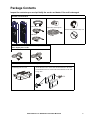
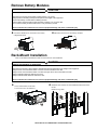
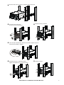
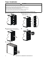
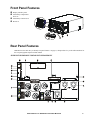
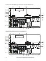
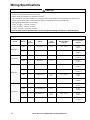
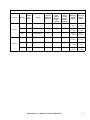
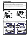
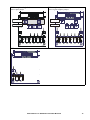
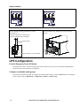
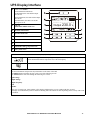
Installation Guide Smart-UPS™On-Line SRT8K/SRT10K Tower/Rack-Mount 6U Safety Messages Read the instructions carefully to become familiar with the equipment before attempting to install, operate, service or maintain the UPS. The following special messages may appear throughout this manual or on the equipment to warn of potential hazards or to call attention to information that clarifies or simplifies a procedure. The addition of this symbol to a Danger or Warning product safety label indicates that an electrical hazard exists which will result in personal injury if the instructions are not followed. The addition of this symbol to a Warning or Caution product safety label indicates that a hazard exists that can result in injury and product damage if the instructions are not followed. Information CAUTION CAUTION indicates a potentially hazardous situation which, if not avoided, can result in minor or moderate injury. CAUTION CAUTION addresses practices not related to physical injury including certain environmental hazards, potential damage or loss of data. Safety and General Information • • • • • • • • • • • • Adhere to all national and local electrical codes. All wiring must be performed by a qualified electrician. Changes and modifications to this unit not expressly approved by APC could void the warranty. This unit is intended only for indoor use in a controlled environment. Do not operate this unit in direct sunlight, in contact with fluids, or where there is excessive dust or humidity. Be sure the air vents on the unit are not blocked. Allow adequate space for proper ventilation. For a UPS with a factory installed power cord, connect the UPS power cable directly to a wall outlet. Do not use surge protectors or extension cords. The battery typically lasts for two to five years. Environmental factors impact battery life. Elevated ambient temperatures, high humidity, poor quality mains power, and frequent short duration discharges will shorten battery life. The equipment is heavy. Always practice safe lifting techniques adequate for the weight of the equipment. The batteries are heavy. Remove the batteries before installing the UPS and external battery packs (XLBPs), in a rack. Always install XLBPs at the bottom in rack-mount configurations. The UPS must be installed above the XLBPs. Always install peripheral equipment above the UPS in rack-mount configurations. • Additional safety information can be found in the Safety Guide supplied with this unit. Deenergizing safety The UPS contains internal batteries and may present a shock hazard even when disconnected from the branch circuit (mains). Before installing or servicing the equipment verify that the: • Mains circuit breaker is in the OFF position. • Internal UPS batteries are removed. • XLBP battery modules are disconnected. Electrical safety • For models with a hardwired input, the connection to the branch circuit (mains) must be performed by a qualified electrician. • 230 V models only: In order to maintain compliance with the EMC directive for products sold in Europe, output cords attached to the UPS must not exceed 10 meters in length. • The protective earth conductor for the UPS carries the leakage current from the load devices (computer equipment). An insulated ground conductor is to be installed as part of the branch circuit that supplies the UPS. The conductor must have the same size and insulation material as the grounded and ungrounded branch circuit supply conductors. The conductor will typically be green and with or without a yellow stripe. • The ground conductor must be grounded to earth at the service equipment, or if supplied by a separately derived system, at the supply transformer or motor generator set. Battery safety • Before installing or replacing the batteries, remove jewelry such as wristwatches and rings. High short circuit current through conductive materials could cause severe burns. • Do not dispose of batteries by burning them. The batteries may explode. • Do not open or mutilate batteries. Released electrolyte is harmful to the skin and eyes, and may be toxic. Hardwire safety • Verify that all branch circuit (mains) and low voltage (control) circuits are deenergized, and locked out before installing cables or making connections, whether in the junction box or to the UPS. • Wiring by a qualified electrician is required. • Check national and local codes before wiring. • Strain relief is required for all hardwiring (not supplied). • All openings that allow access to UPS hardwire terminals must be covered. Failure to do so may result in personal injury or equipment damage. • Select wire size and connectors according to national and local codes. General information • The UPS will recognize as many as 10 external battery packs connected to the UPS. However there is no limit to the number of XLBPs that can be used with the UPS. Note: For each XLBP added, increased recharge time will be required. • The model and serial numbers are located on a small, rear panel label. For some models, an additional label is located on the chassis under the front bezel. • Always recycle used batteries. • Recycle the package materials or save them for reuse. FCC Class A radio frequency warning This equipment has been tested and found to comply with the limits for a Class A digital device, pursuant to part 15 of the FCC Rules. These limits are intended to provide reasonable protection against harmful interference when the equipment is operated in a commercial environment. This equipment generates, uses, and can radiate radio frequency energy and, if not installed and used in accordance with the instruction manual, may cause harmful interference to radio communications. Operation of this equipment in a residential area is likely to cause harmful interference in which case the user will be required to correct the interference at his own expense. 2 Smart-UPS On-Line SRT8K/10K Tower/Rack-Mount 6U Package Contents Inspect the contents upon receipt. Notify the carrier and dealer if the unit is damaged. Included with all models Front bezels Console to DB9 cable EPO Terminal block User Documentation CD. User Do c ume nta tio n RJ45 to DB9 cable Temperature sensor probe Network Management Utility CD USB cable Included with XLI/XLT-IEC models only Three output power cords One C13/C14, 10 A, 2 m Two C19/C20, 16 A, 2.5 m Included with Rack-Mount models only su0434a Rail Kit with instructions and hardware • 2 pairs of rack-mount brackets for installing rails in a rack. • 16 flat head screws to secure rack-mount brackets to the UPS • 8 ornamental screws to secure rack-mount brackets to the rails • 6 cage nuts x6 x16 x8 Smart-UPS On-Line SRT8K/10K Tower/Rack-Mount 6U 3 Specifications For additional specifications refer to the APC web site, www.apc.com. Environmental Temperature Maximum Elevation Operating 0º to 40º C (32º to 104º F) Storage -15º to 45º C (5º to 113º F) Operating 0 - 3,000 m (0 - 10,000 ft) Storage 0 - 15,000 m (50,000 ft) Humidity 0% to 95% relative humidity, non-condensing Protection Class IP 20 rating Note: Charge the battery modules every six months during storage. Environmental factors impact battery life. Elevated ambient temperatures, high humidity, poor quality mains power, and frequent short duration discharges will shorten battery life. Physical The UPS is heavy. Follow all lifting guidelines. Lifting guidelines >55 kg (>120 lb) Unit weight without packaging 111.8 kg (246 lb) Unit weight with packaging Rack-Mount models: 126.8 kg (279 lb) Tower models: 130 kg (286 lb) Unit dimensions without packaging Height x Width x Depth 263 mm x 432 mm x 715 mm 10.35 in x 17 in x 28.15 in Unit dimensions with packaging Height x Width x Depth 461 mm x 600 mm x 1000 mm 18.2 in x 23.62 in x 39.4 in The model and serial numbers are on a small label located on the rear panel. Battery Battery type Replacement battery module Maintenance free, leak proof, sealed, lead acid APCRBC140 This UPS has hot swappable battery modules. Replacement is a safe procedure, isolated from electrical hazards. Refer to the appropriate replacement battery user manual for installation instructions. Contact your dealer or go the APC web site, www.apc.com for information on replacement batteries. Number of battery modules 4 battery modules Voltage for each battery module Total voltage for the UPS Ah rating 96 VDC ± 192 VDC 5.1 Ah per battery module XLBP cable length 500 mm (19.7 in) 4 Smart-UPS On-Line SRT8K/10K Tower/Rack-Mount 6U Electrical Models Rating SRT8KXLT SRT8KRMXLT SRT8KXLT-IEC SRT8KRMXLT-IEC 8 kVA/8 kW SRT8KXLI SRT8KRMXLI SRT10KXLT SRT10KRMXLT SRT10KXLT-IEC SRT10KRMXLT-IEC 10 kVA/10 kW SRT10KXLI SRT10KRMXLI Output Output Frequency 50 Hz/60 Hz ± 3 Hz Nominal Output Voltage SRT8KXLI/SRT8KRMXLI/SRT10KXLI/SRT10KRMXLI: 220Vac/230Vac/240Vac SRT8KXLT/SRT8KRMXLT/SRT10KXLT/SRT10KRMXLT: 208Vac/240Vac SRT8KXLT-IEC/SRT8KRMXLT-IEC/SRT10KXLT-IEC/SRT10KRMXLT-IEC: 208Vac/240Vac Input Input Frequency 40 Hz-70 Hz Nominal Input Voltage SRT8KXLI/SRT8KRMXLI/SRT10KXLI/SRT10KRMXLI: 220Vac/230Vac/240Vac SRT8KXLT/SRT8KRMXLT/SRT10KXLT/SRT10KRMXLT: 208Vac/240Vac SRT8KXLT-IEC/SRT8KRMXLT-IEC/SRT10KXLT-IEC/SRT10KRMXLT-IEC: 208Vac/240Vac Smart-UPS On-Line SRT8K/10K Tower/Rack-Mount 6U 5 Remove Battery Modules CAUTION DAMAGE TO EQUIPMENT OR PERSONNEL • The equipment is heavy. Each battery module weighs 17 kg (37 lb). • Always practice safe lifting techniques adequate for the weight of the equipment. • Remove the battery modules before installing the UPS. • Use the battery module handle to slide the battery modules in or out of the UPS. • Do not use the battery module handle to lift or carry the battery module. Failure to follow these instructions can result in equipment damage and minor or moderate injury Loosen the thumbscrews, and remove the battery compartment doors. Disconnect and remove four battery modules. su o0 x4 78 s uo 0 787a 6a Rack-Mount Installation Refer to the Rail Kit Installation Guide for instructions on rail installation. CAUTION DAMAGE TO EQUIPMENT OR PERSONNEL • The equipment is heavy. Always practice safe lifting techniques adequate for the weight of the equipment. • Always use the recommended number of screws to secure brackets to the UPS. • Always use the recommended number of screws and cage nuts to secure the UPS to the rack. • Always install the UPS at the bottom of the rack. • Always install the XLBP below the UPS in the rack. Failure to follow these instructions can result in equipment damage and minor or moderate injury Install the rails. Follow the rail installation instruction in the rail kit. Install six cage nuts. Secure four brackets to the UPS. Use four screws in each bracket. suo 07 73a x8 x3 x3 suo0788a x8 6 Smart-UPS On-Line SRT8K/10K Tower/Rack-Mount 6U Rest the UPS on the rail shelves. Slide the UPS into the rack. suo0774a leat rail c Install four battery modules. suo0775a x4 suo0776a Secure the UPS to the rack. Use two screws in each bracket. x4 suo0777a After the UPS is hardwired to branch circuit mains complete steps 6-8. Connect all four battery modules. Smart-UPS On-Line SRT8K/10K Tower/Rack-Mount 6U suo0779a x4 Install two bezels. suo0778a Reinstall the battery compartment doors. Tighten the thumbscrews to secure the doors. 7 Tower Installation CAUTION DAMAGE TO EQUIPMENT OR PERSONNEL • The equipment is heavy. Each battery module weighs 17 kg (37 lb). • Always practice safe lifting techniques adequate for the weight of the equipment. • Remove the battery modules before installing the UPS. • Use the battery module handle to slide the battery modules in or out of the UPS. • Do not use the battery module handle to lift or carry the battery module. Failure to follow these instructions can result in equipment damage and minor or moderate injury Install four battery modules. s uo0 After the UPS is hardwired to branch circuit mains, complete steps 2-5. Connect all four battery modules. 78 2a suo0 Reinstall the battery compartment doors. Tighten the thumbscrews to secure the doors. 7 83b x4 s uo0 s uo0 7 85a 7 81a su o0 78 4 a Install two bezels. 8 Smart-UPS On-Line SRT8K/10K Tower/Rack-Mount 6U Front Panel Features Display interface panel UPS battery compartment doors x2 UPS battery connectors x4 suo0796a Bezels x2 Rear Panel Features Note: Refer to the table “Key to identify rear panel features” on page 11, that provides a key to the callout numbers for the rear panel graphics depicted in this manual. Serial USB 10 / 100 Console Network Reset SRT8KXLT/SRT8KRMXLT/SRT10KXLT/SRT10KRMXLT 1 2 3 4 3 4 BATT COMM GROUP 1 20 AMP MAX 2 GROUP 2 20 AMP MAX NC 1 +- 192VDC HARDWIRED OUTPUT NO EPO GROUP 3 30 AMP MAX suo0772a Smart-UPS On-Line SRT8K/10K Tower/Rack-Mount 6U 9 Serial USB 10 / 100 Console Network Reset SRT8KXLT-IEC/SRT8KRMXLT-IEC/SRT10KXLT-IEC/SRT10KRMXLT-IEC NO 1 2 3 4 EPO 2 3 4 BATT COMM GROUP 2 20 AMP MAX +- 192VDC HARDWIRED OUTPUT GROUP 1 20 AMP MAX NC 1 GROUP 3 15 AMP MAX suo0770a Serial USB 10 / 100 Console Network Reset SRT8KXLI/SRT8KRMXLI/SRT10KXLI/SRT10KRMXLI NO 1 2 3 4 EPO 2 3 4 BATT COMM GROUP 2 16 AMP MAX +- 192VDC HARDWIRED OUTPUT GROUP 1 16 AMP MAX NC 1 GROUP 3 10 AMP MAX suo0771a 10 Smart-UPS On-Line SRT8K/10K Tower/Rack-Mount 6U Key to identify rear panel features Network port Use the Network port to connect the UPS to the network. Console port Use the Console port to configure the network management features. Universal I/O port Use to connect: • Temperature sensor AP9335T (supplied) • Temperature/humidity sensor AP9335TH (not supplied) • Relay input/output connector AP9810 (not supplied), supports two input contacts and one output relay USB port The USB port is used to connect either a server for native operating system communications, or for software to communicate with the UPS. Note: Serial and USB communication should not be used simultaneously. Use either the Serial Com or the USB port. Serial Com The Serial Com port is used to communicate with the UPS. Use only interface kits supplied or approved by APC by Schneider Electric. Any other serial interface cable will be incompatible with the UPS connector. EPO terminal The Emergency Power Off (EPO) terminal allows the user to connect the UPS to a central EPO system. Controllable outlet Connect electronic devices to these outlets. group 1, with In the event an overload condition occurs, disconnect nonessential equipment. Then reset the circuit breaker. circuit breaker Controllable outlet Connect electronic devices to these outlets. group 2, with In the event an overload condition occurs, disconnect nonessential equipment. Then reset the circuit breaker. circuit breaker Controllable outlet Connect electronic devices to these outlets. group 3, with In the event an overload condition occurs, disconnect nonessential equipment. Then reset the circuit breaker. circuit breaker AC output inspection panel Remove the panel to inspect the output terminal block wiring configuration. The terminal block is located behind the inspection cover. Refer to “Wiring Specifications” on page 9 for hardwire specifications. AC input inspection panel Remove the panel to inspect the input terminal block wiring configuration. The terminal block is located behind the inspection cover. Refer to “Wiring Specifications” on page 9 for hardwire specifications. AC hardwire knockouts Remove the 38.1 mm (1.5 in) knockout panels for AC input and output hardwiring. Install appropriate strain reliefs (not supplied). Hardwire box input/output Remove the box to connect input and output wires to the hardwire terminal blocks. Chassis ground screws The UPS and XLBPs have ground screws for connecting the ground leads. Prior to connecting a ground lead, disconnect the UPS from mains power. External battery power and communication connectors Use the external battery power and communication cables to connect the UPS and XLBP. XLBPs provide extended runtime during power outages. The UPS will automatically recognize up to 10 external battery packs. SmartSlot The SmartSlot can be used to connect optional management accessories. PRL COMM port This port is not used with these products. Reset button Use the Reset button to restart the Network Management Interface. Note: A restart of the Network Management Interface does not affect UPS operation. Smart-UPS On-Line SRT8K/10K Tower/Rack-Mount 6U 11 Wiring Specifications CAUTION DAMAGE TO EQUIPMENT OR PERSONNEL • Adhere to all national and local electrical codes. • Wiring should be performed by a qualified electrician. • The UPS must be wired into a branch circuit, equipped with a circuit breaker rated as specified in the tables below. • Actual wire size must comply with required amp capacity and national and local electrical codes. • Recommended input terminal screw torque: 10 mm2 (6 AWG) = 5.09 Nm (45 lbf-in) 16 mm2 (4 AWG) = 5.09 Nm (45 lbf-in) 2.5 mm2 (12 AWG) = 3.969 Nm (35 lbf-in) Failure to follow these instructions can result in equipment damage and minor or moderate injury Single Feed System Wiring Number of Phases Voltage Current Full External Input Circuit Load Breaker Mains (nominal) (typical) Input 1 208/240 Vac 47 A Output 1 208/240 Vac 40 A Input 1 208/240 Vac 56 A Output 1 208/240 Vac 49 A Input 1 220/230/240 Vac 44 A Output 1 220/230/240 Vac 38 A Input 3 380/400/415 Vac 15 A 44 A* Output 1 220/230/240 Vac 38 A Input 1 220/230/240 Vac 54 A Output 1 220/230/240 Vac 47 A Input 3 380/400/415 Vac 18 A 54 A* Output 1 220/230/240 Vac 47 A 60 A / 2-pole SRT8KXLT 10 mm2 (6 AWG) 10 mm2 (6 AWG) 70 A / 2-pole SRT10KXLT 16 mm2 (4 AWG) 10 mm2 (6 AWG) 63 A / 2-pole 10 mm2 (6 AWG) 10 mm2 (6 AWG) SRT8KXLI 63 A / 4-pole 10 mm2 (6 AWG) 10 mm2 (6 AWG) 80 A / 2-pole 16 mm2 (4 AWG) 10 mm2 (6 AWG) SRT10KXLI 80 A / 4-pole * Phase 1 (L1) current while in bypass mode 12 Wire Size Mains (typical) Smart-UPS On-Line SRT8K/10K Tower/Rack-Mount 6U 16 mm2 (4 AWG) 10 mm2 (6 AWG) Dual Feed System SRT8KXLI SRT10KXLI Voltage Current Full Load (nominal) External Input Circuit Breaker Mains (typical) External Input Circuit Bypass Mains (typical) Wire Size Mains (typical) Wire Size Bypass (typical) 1 220/230/240 Vac 44 A 63 A / 2-pole 63 A / 2-pole 10 mm2 (6 AWG) 10 mm2 (6 AWG) Input 3 380/400/415 Vac 15 A 20 A / 4-pole 63 A / 2-pole 2.5 mm2 (12 AWG) 10 mm2 (6 AWG) Output 1 220/230/240 Vac 38 A 10 mm2 (6 AWG) 10 mm2 (6 AWG) Input 1 220/230/240 Vac 54 A 80 A / 2-pole 80 A / 2-pole 16 mm2 (4 AWG) 16 mm2 (4 AWG) Input 3 380/400/415 Vac 18 A 25 A / 4-pole 80 A / 2-pole 2.5 mm2 (12 AWG) 16 mm2 (4 AWG) Output 1 220/230/240 Vac 47 A 10 mm2 (6 AWG) 10 mm2 (6 AWG) Wiring Number of Phases Input Smart-UPS On-Line SRT8K/10K Tower/Rack-Mount 6U 13 Hardwire the UPS CAUTION DAMAGE TO EQUIPMENT OR PERSONNEL • Disconnect the mains input circuit breaker before installing or servicing the UPS or connected equipment. • Disconnect internal and external batteries before installing or servicing the UPS or connected equipment. • The UPS contains internal and external batteries that may present a shock hazard even when disconnected from the mains. • UPS AC hardwired and pluggable outlets may be energized by remote or automatic control at any time. • Disconnect equipment from the UPS before servicing any equipment. • Do not use the UPS as a safety disconnect. • Install appropriate strain reliefs (not supplied). Failure to follow these instructions can result in equipment damage and minor or moderate injury Remove the five #2 Phillips screws that secure the hardwire box to the UPS. Pull the hardwire box out of the UPS. Install strain reliefs (not supplied), for the hardwire configuration that will be used. input input output s uo 0 789a s uo 0 x5 804a Input hardwire In the following graphics, the arrows identify jumper locations and where wires should be secured. The jumpers use T25 Torx screws. The terminal blocks use 4 mm (5/32 in) Hex screws. XLI single phase, single feed XLI single phase, dual feed Leave bypass and phase jumpers in place. Remove bypass jumper. bypass jumper bypass jumper phase jumper phase jumper N B1 L3 L2 L1 N N B1 suo0791a 14 Smart-UPS On-Line SRT8K/10K Tower/Rack-Mount 6U L3 L2 L1 N suo0792a XLI three phase, single feed XLI three phase, dual feed Remove phase jumper. Remove bypass and phase jumpers. bypass jumper bypass jumper phase jumper phase jumper N B1 L3 L2 L1 N N suo0790a B1 L3 L2 L1 N suo0793a XLT L2 L1 suo0795a Smart-UPS On-Line SRT8K/10K Tower/Rack-Mount 6U 15 Output hardwire XLT models L2 L1 N suo0794b suo0794a L1 XLI models Install the ground wire. Strip the insulation off the ground cable to expose the ground wire. Secure the exposed wire with the lug A. Secure the insulated cable with lug B. Reinstall the hardwire box in the UPS. Secure the hardwire box with the five screws previously removed. lug A lug B insulated cable Strip 19.05 mm (.75 in) insulation s uo 0 789b x5 UPS Configuration Connect Emergency Power Off feature For instructions on how to connect the Emergency Power Off (EPO) switch, refer to the Operation and Maintenance manual on the User Documentation CD (supplied). Configure controllable outlet groups The outlets on the UPS are grouped. To configure the controlled outlet features, use the Advanced menus on the display interface and navigate to: Main Menu > Configuration > Outlets > Outlet Group. 16 Smart-UPS On-Line SRT8K/10K Tower/Rack-Mount 6U UPS Display Interface POWER ON/OFF button Button illumination indications: -No illumination, the UPS and the output power are off -White illumination, the UPS and the output power are on -Red illumination, the UPS is on and the output power is off Load icon Disable/mute audible alarm icon LOAD Output 230.0 v UPS status information On-Line 1 2 3 Operation mode icons ESCAPE button OK button su0870a UP/DOWN buttons Controllable outlet group status icons Battery status icons The icons on the LCD display interface screen may vary depending on the installed firmware version. LOAD Load icon: The approximate load capacity percentage is indicated by the number of load bar sections illuminated. Each bar represents 16% of the load capacity. Mute icon: Indicates the audible alarm is disabled/mute. UPS Status Information The status information field provides key information on the status of the UPS. The Standard menu will allow the user to select one of the following screens. The Advanced menu will scroll through the following five screens. Input Voltage Output Voltage Output Frequency Load Runtime In the case of a UPS event, status updates will be displayed defining the event or condition that has occurred. The display screen illuminates yellow to indicate a Warning and red to indicate an Alert depending on the severity of the event or condition. Smart-UPS On-Line SRT8K/10K Tower/Rack-Mount 6U 17 Operation Mode Icons On-Line mode: The UPS is supplying conditioned mains power to connected equipment. Bypass mode: The UPS is in Bypass mode and the connected equipment will receive mains power as long as the input voltage and frequency are within the configured limits. Green mode: When in Green mode mains power is sent directly to the load. In the event of a mains power outage, there will be an interruption in power to the load of up to 8 ms while the UPS switches to On-Line or Battery mode. When enabling Green mode consideration should be given to devices that may be sensitive to power fluctuations. Battery mode: The UPS is supplying battery power to connected equipment. Controllable Outlet Group Icons Controllable Outlet Group Power Available: The number next to the icon identifies the specific outlet groups that have available power. Controllable Outlet Group Power Not Available: The number next to the icon identifies specific outlet groups that do not have available power. Battery Status Icons Battery Charge Status: Indicates the battery charge status. Battery Charge In Progress: Indicates the battery is charging. 18 Smart-UPS On-Line SRT8K/10K Tower/Rack-Mount 6U Display interface operation Use the UP/DOWN buttons to scroll through the options. Press the OK button to accept the selected option. Press the ESC button to return to the previous menu. Menu overview The display interface has Standard and Advanced menu screens. The preference for Standard or Advanced menu selections is made during initial installation and can be changed at any time through the Configuration menu. The Standard menus include the most commonly used options. The Advanced menus provide additional options. Note: Actual menu screens may differ by model and firmware version. Refer to the UPS Operation Manual for menu configuration details. LCD display interface angle adjustment The angle of the LCD display interface can be adjusted for ease in viewing the displayed messages. 1. Remove the front bezel. 2. Locate the button on the bottom of the display interface panel. 3. Press the button and slide the bottom of the LCD display interface screen out. An audible click will be heard when the screen reaches the maximum angle. su 09 26 a Select models are ENERGY STAR® qualified. For more information go to www.apc.com/site/recycle/index.cfm/energy-efficiency/energy-star/ Smart-UPS On-Line SRT8K/10K Tower/Rack-Mount 6U 19 Limited Factory Warranty Schneider Electric IT Corporation (SEIT), warrants its products to be free from defects in materials and workmanship for a period of three (3) years excluding the batteries, which are warranted for two (2) years from the date of purchase. The SEIT obligation under this warranty is limited to repairing or replacing, at its own sole option, any such defective products. Repair or replacement of a defective product or part thereof does not extend the original warranty period. This warranty applies only to the original purchaser who must have properly registered the product within 10 days of purchase. Products may be registered online at warranty.apc.com. SEIT shall not be liable under the warranty if its testing and examination disclose that the alleged defect in the product does not exist or was caused by end user or any third person misuse, negligence, improper installation, testing, operation or use of the product contrary to SEIT recommendations of specifications. Further, SEIT shall not be liable for defects resulting from: 1) unauthorized attempts to repair or modify the product, 2) incorrect or inadequate electrical voltage or connection, 3) inappropriate on site operation conditions, 4) Acts of God, 5) exposure to the elements, or 6) theft. In no event shall SEIT have any liability under this warranty for any product where the serial number has been altered, defaced, or removed. EXCEPT AS SET FORTH ABOVE, THERE ARE NO WARRANTIES, EXPRESS OR IMPLIED, BY OPERATION OF LAW OR OTHERWISE, APPLICABLE TO PRODUCTS SOLD, SERVICED OR FURNISHED UNDER THIS AGREEMENT OR IN CONNECTION HEREWITH. SEIT DISCLAIMS ALL IMPLIED WARRANTIES OF MERCHANTABILITY, SATISFACTION AND FITNESS FOR A PARTICULAR PURPOSE. SEIT EXPRESS WARRANTIES WILL NOT BE ENLARGED, DIMINISHED, OR AFFECTED BY AND NO OBLIGATION OR LIABILITY WILL ARISE OUT OF, SEIT RENDERING OF TECHNICAL OR OTHER ADVICE OR SERVICE IN CONNECTION WITH THE PRODUCTS. THE FOREGOING WARRANTIES AND REMEDIES ARE EXCLUSIVE AND IN LIEU OF ALL OTHER WARRANTIES AND REMEDIES. THE WARRANTIES SET FORTH ABOVE CONSTITUTE SEIT’S SOLE LIABILITY AND PURCHASER EXCLUSIVE REMEDY FOR ANY BREACH OF SUCH WARRANTIES. SEIT WARRANTIES EXTEND ONLY TO ORIGINAL PURCHASER AND ARE NOT EXTENDED TO ANY THIRD PARTIES. IN NO EVENT SHALL SEIT, ITS OFFICERS, DIRECTORS, AFFILIATES OR EMPLOYEES BE LIABLE FOR ANY FORM OF INDIRECT, SPECIAL, CONSEQUENTIAL OR PUNITIVE DAMAGES, ARISING OUT OF THE USE, SERVICE OR INSTALLATION OF THE PRODUCTS, WHETHER SUCH DAMAGES ARISE IN CONTRACT OR TORT, IRRESPECTIVE OF FAULT, NEGLIGENCE OR STRICT LIABILITY OR WHETHER SEIT HAS BEEN ADVISED IN ADVANCE OF THE POSSIBILITY OF SUCH DAMAGES. SPECIFICALLY, SEIT IS NOT LIABLE FOR ANY COSTS, SUCH AS LOST PROFITS OR REVENUE, WHETHER DIRECT OR INDIRECT, LOSS OF EQUIPMENT, LOSS OF USE OF EQUIPMENT, LOSS OF SOFTWARE, LOSS OF DATA, COSTS OF SUBSTITUANTS, CLAIMS BY THIRD PARTIES, OR OTHERWISE. NOTHING IN THIS LIMITED WARRANTY SHALL SEEK TO EXCLUDE OR LIMIT SEIT LIABILITY FOR DEATH OR PERSONAL INJURY RESULTING FROM ITS NEGLIGENCE OR ITS FRAUDULENT MISREPRESENTATION OF TO THE EXTENT THAT IT CANNOT BE EXCLUDED OR LIMITED BY APPLICABLE LAW. To obtain service under warranty you must obtain a Returned Material Authorization (RMA) number from customer support. Customers with warranty claims issues may access the SEIT worldwide customer support network through the APC web site: www.apc.com. Select your country from the country selection drop down menu. Open the Support tab at the top of the web page to obtain information for customer support in your region. Products must be returned with transportation charges prepaid and must be accompanied by a brief description of the problem encountered and proof of date and place of purchase. © 2014 APC by Schneider Electric. APC, the APC logo, Smart-UPS and PowerChute are owned by Schneider Electric Industries S.A.S. or their affiliated companies. All other trademarks are property of their respective owners. EN 990-4816A 06/2014