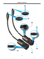
1
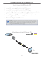
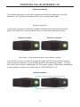
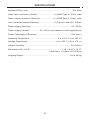
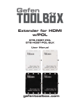
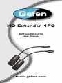
®
EXT-HD-CP-FM10
User Manual
www.gefen.com
ASKING FOR ASSISTANCE
Technical Support:
Telephone
Fax
(818) 772-9100
(800) 545-6900
(818) 772-9120
Technical Support Hours:
8:00 AM to 5:00 PM Monday through Friday, Pacific Time
Write To:
Gefen LLC
c/o Customer Service
20600 Nordhoff St
Chatsworth, CA 91311
www.gefen.com
[email protected]
Notice
Gefen LLC reserves the right to make changes in the hardware, packaging, and
any accompanying documentation without prior written notice.
HD Extender 1FO is a trademark of Gefen LLC
HDMI, the HDMI logo, and High-Definition Multimedia Interface are
trademarks or registered trademarks of HDMI Licensing in the United States and
other countries.
© 2012 Gefen, LLC. All rights reserved.
All trademarks are the property of their respective owners.
Rev A1
CONTENTS
1
Introduction
2
Operation Notes
3
Features
4
Cable Layout
5
Cable Descriptions
6
Connecting the HD Extender 1FO
6
Wiring Diagram
7
Operating the HD Extender 1FO
8
Specifications
9
Warranty
INTRODUCTION
Congratulations on your purchase of the Gefen HD Extender 1FO.
Your complete satisfaction is very important to us.
Gefen
Gefen delivers innovative, progressive computer and electronics add-on solutions
that harness integration, extension, distribution and conversion technologies.
Gefen’s reliable, plug-and-play products supplement cross-platform computer
systems, professional audio/video environments and HDTV systems of all sizes
with hard-working solutions that are easy to install and simple to operate.
The Gefen HD Extender 1FO
The HDMI fiber optic pigtail module extender with HDCP support extends HDMI
up to 1000 feet (300 meters) using a single-strand 50/125μm multimode (OM2)
SC-terminated fiber optic cable. It supports resolutions up to 1080p Full HD and
HD lossless audio formats like LCPM 7.1 audio, Dolby® Digital Plus, Dolby®
TrueHD, and DTS-HD® Master Audio™. Optical signal transmission provides
galvanic isolation and immunity to electromagnetic interference compared to
similar copper based extension modules. The pigtail design of the Sender and
Receiver modules relieves stress and clutter on the source and display
connector panels. Their compact design makes them ideal for fitting neatly
behind equipment for a clean installation, making it a great way to easily extend
HDMI.
How It Works
The Sender pigtail end plugs into the HDMI source. The Receiver pigtail end
plugs into the HDTV display. Connect a single-strand 50/125μm multimode
(OM2) SC-terminated fiber optic cable from the Sender to the Receiver module.
Plug the power supply into the Receiver module and a vibrant Hi-Def picture will
appear on your display.
1
OPERATION NOTES
PLEASE READ THESE NOTES BEFORE INSTALLING OR
OPERATING THE HD EXTENDER 1FO
•
In most situations, the Sender pigtail module does not need to be externally
powered unless the source does not supply enough power through the
HDMI connector. If the Sender requires a separate power supply only use
Gefen part no. EXT-PS52AIP-1.3. Using a different power supply other
than the recommended type may cause fatal damage to the Sender pigtail
module.
2
FEATURES
Features
•
Extends HDMI up to 1000 feet (300 meters) using a single-strand 50/125μm
multimode (OM2) SC-terminated fiber optic cable
•
Supports resolutions up 1080p Full HD
•
Supports HD lossless audio: LCPM 7.1 audio, Dolby® Digital Plus, Dolby®
TrueHD, and DTS-HD® Master Audio™
•
Fiber optic transmission eliminates electromagnetic interference (EMI)
•
Pigtail design relieves stress and clutter on the source and display
connector panels
•
3DTV pass-through
•
DDC bidirectional support
•
HDCP pass-through
•
Supports Deep Color
•
Compact Sender and Receiver modules provide a clean, easy installation
•
FCC and CE compliant for EMI/RFI emission
Package Includes
(1) HD Extender 1FO - Sender Pigtail module
(1) HD Extender 1FO - Receiver Pigtail module
(1) 5V DC power supply
(1) Quick-Start Guide
3
CABLE LAYOUT
6
3
7
4
5
1
2
4
CABLE DESCRIPTIONS
1
Power Indicator (Sender module)
This LED will glow bright green when the Hi-Def source is supplying sufficient
power to the Sender module. If the LED flashes green, then the source is
unable to power the Sender module. See page 7 for more information.
2
Fiber Optic Connector (Sender module)
Connect an SC-terminated fiber optic cable from the Sender pigtail module to
the SC fiber connector on the Receiver pigtail module.
3
HDMI Connector, male (Sender module)
Connect this end of the Sender pigtail module to the Hi-Def source.
4
Power Indicator (Receiver module)
This LED will glow bright green when one of the included 5V DC power supplies
is connected to the power receptacle on the Receiver module.
5
Fiber Optic Connector (Receiver module)
Connect the SC-terminated fiber optic cable from the Sender pigtail module to
the SC fiber connector on the Receiver pigtail module.
6
HDMI Connector, male (Receiver module)
Connect this end of the Receiver pigtail module to the HDTV display.
7
Power Receptacle (Sender / Receiver module)
Connect the included 5V DC power supply to this power receptacle. Both the
Sender and Receiver module have power receptacles. However, the Sender
module does not need to be externally powered unless the source does not
supply enough power through the HDMI connector.
5
CONNECTING THE HD EXTENDER 1FO
How to Connect the HD Extender 1FO
1.
Connect the Sender pigtail module to the Hi-Def source.
2.
Connect the Receiver pigtail module to the HDTV display.
3.
Connect a single strand of SC-terminated fiber optic cable between the fiber
optic connectors on the Sender and Receiver pigtail modules.
4.
Connect the included 5V DC power supply to power receptacle on the
Receiver pigtail module.
5.
Power-on the display and Hi-Def source.
NOTE: The Sender module does not need to be externally powered
unless the Hi-Def source does not supply enough power through the
HDMI connector. The Receiver module must always be powered
using the included 5V DC power supply.
Wiring Diagram for the HD Extender 1FO
HDMI
FIBER OPTIC CABLE
Computer
Sender
der
Receiver
eceiver
HD
Display
EXT-HD-CP-FM10
6
OPERATING THE HD EXTENDER 1FO
Power Indicators
The power indicators on both the Sender and Receiver modules of the HD
Extender 1FO provide information about the current power state.
Normal operation
If the power indicator on both the Sender and Receiver module glows bright
green, then both the Sender and Receiver module have sufficient power.
Sender module
Receiver module
No power / insufficient power on the Sender module
If the Hi-Def source is unable to supply the required 5V to the Sender module,
then the power indicator on the Sender module will flash bright green. If this is
the case, then connect a secondary 5V DC power supply to the power receptacle
on the Sender module (use Gefen part no. EXT-PS52AIP-1.3).
Sender module
7
SPECIFICATIONS
Maximum Pixel Clock............................................................................... 225 MHz
Video Input Connector (Sender)............................. (1) HDMI Type-A, 19-pin, male
Video Output Connector (Receiver)....................... (1) HDMI Type-A, 19-pin, male
Link Connector (Sender/Receiver).......................... (1) Type SC fiber (50 /125μm)
Power Supply (Receiver)....................................................................... 5V / 2A DC
Power Supply (Sender).................. 5V / 2A DC (not needed for most applications)
Power Consumption (Receiver)........................................................... 1.5W (max.)
Operating Temperature.................................................. 0 to +122 °F (0 to +50 °C)
Storage Temperature................................................. -4 to +158 °F (-20 to +70 °C)
Relative Humidity................................................................................. 10% to 80%
Dimensions (W x H x D)........................................................ 1.18” x 0.47” x 10.71”
(29.97mm x 11.93mm x 272.03mm)
Shipping Weight.................................................................................. 1lb (0.45 kg)
8
WARRANTY
Gefen warrants the equipment it manufactures to be free from defects in material
and workmanship.
If equipment fails because of such defects and Gefen is notified within two (2)
years from the date of shipment, Gefen will, at its option, repair or replace the
equipment, provided that the equipment has not been subjected to mechanical,
electrical, or other abuse or modifications. Equipment that fails under conditions
other than those covered will be repaired at the current price of parts and labor in
effect at the time of repair. Such repairs are warranted for ninety (90) days from
the day of reshipment to the Buyer.
This warranty is in lieu of all other warranties expressed or implied, including
without limitation, any implied warranty or merchantability or fitness for any
particular purpose, all of which are expressly disclaimed.
1.
Proof of sale may be required in order to claim warranty.
2.
Customers outside the US are responsible for shipping charges to and from
Gefen.
3.
Copper cables are limited to a 30 day warranty and cables must be in their
original condition.
The information in this manual has been carefully checked and is believed to
be accurate. However, Gefen assumes no responsibility for any inaccuracies
that may be contained in this manual. In no event will Gefen be liable for
direct, indirect, special, incidental, or consequential damages resulting from
any defect or omission in this manual, even if advised of the possibility of such
damages. The technical information contained herein regarding the features and
specifications is subject to change without notice.
For the latest warranty coverage information, refer to the Warranty and Return
Policy under the Support section of the Gefen Web site at www.gefen.com.
PRODUCT REGISTRATION
Please register your product online by visiting the Register Product page
under the Support section of the Gefen Web site.
9
Rev A1
Pb
This product uses UL or CE listed power supplies.