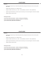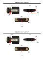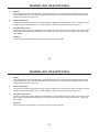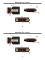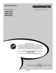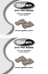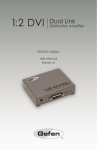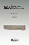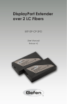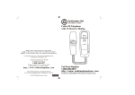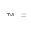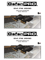
1
DVI FM 2000
GEF-DVI-FM2000
User Manual
DVI FM 2000
GEF-DVI-FM2000
User Manual
ASKING FOR ASSISTANCE
Technical Support:
Telephone
(818) 772-9100
(800) 545-6900
Fax
(818) 772-9120
Technical Support Hours:
8:00 AM to 5:00 PM Monday thru Friday, Pacific Time
Write To:
Gefen, LLC
c/o Customer Service
20600 Nordhoff St
Chatsworth, CA 91311
www.gefenpro.com
[email protected]
Notice
Gefen, LLC reserves the right to make changes in the hardware, packaging, and any accompanying
documentation without prior written notice.
DVI FM 2000 Extender is a trademark of Gefen, LLC
© 2011 Gefen, LLC. All rights reserved.
All trademarks are the property of their respective owners.
Rev A4
CONTENTS
1
Introduction
2
Operation Notes
3
Features
4
Sender unit Layout
5
Sender unit Descriptions
6
Receiver unit Layout
7
Receiver unit Descriptions
8
Connecting the DVI FM 2000
9
Wiring Diagram
10
Specifications
11
Warranty
CONTENTS
1
Introduction
2
Operation Notes
3
Features
4
Sender unit Layout
5
Sender unit Descriptions
6
Receiver unit Layout
7
Receiver unit Descriptions
8
Connecting the DVI FM 2000
9
Wiring Diagram
10
Specifications
11
Warranty
INTRODUCTION
Congratulations on your purchase of the GefenPRO DVI FM 2000. Your complete satisfaction is very
important to us.
Gefen
Gefen delivers innovative, progressive computer and electronics add-on solutions that harness
integration, extension, distribution and conversion technologies. Gefen’s reliable, plug-and-play products
supplement cross-platform computer systems, professional audio/video environments, and HDTV
systems of all sizes with hard-working solutions that are easy to implement and simple to operate.
The GefenPRO DVI FM 2000
The Gefen DVI FM 2000 extends a Dual Link DVI source up to 1000 feet (300 meters) using a twostrand multi-mode (50 or 62.5 micron) fiber optic cable. Resolutions up to 1080p Full HD and 3840 x
2400 at 60 Hz are supported.
How It Works
Connect the Sender unit to the Dual Link DVI source. Connect the Receiver unit to the Dual Link DVI
display. Use a two-strand SC-terminated fiber optic cable to connect the Sender unit to the Receiver unit.
Use the included 5V DC power supply to connect the Receiver unit to an available electrical outlet.
1
OPERATION NOTES
READ THESE NOTES BEFORE INSTALLING OR OPERATING
THE DVI DUAL LINK FIBER EXTENDER
•
The DVI Dual Link Fiber Extender only uses multi-mode SC fiber cables.
ATTENTION: Multi-mode fiber optic cable with a core diameter 50 or 62.5
microns is required, in order to extend to distance of 1000 feet (300 meters).
•
The included power supply is required for the Receiver unit. However, if the source does not
supply enough power to the Sender unit, then an optional power supply (Gefen part no.
EXT-PS52AIP-1.3) must be used. In most situations, powering the Sender unit will not be
necessary.
2
FEATURES
Features
•
Extends Dual Link DVI up to 1000 feet (300 meters) using multi-mode (50 or 62.5 micron) fiber
optic cable.
•
Supports HD resolutions up to 1080p Full HD.
•
Supports VESA resolutions up to 1920 x 1200 (WUXGA) and 3840 x 2400 (WQUXGA).
•
Optical signal transmission provides improved immunity from electromagnetic interference (EMI).
•
Supports HDCP pass-through.
Package Includes
(1) DVI Dual Link Fiber Extender - Sender unit (GEF-DVI-FM2000S)
(1) DVI Dual Link Fiber Extender - Receiver unit (GEF-DVI-FM2000R)
(1) 5V / 2A DC Power Supply (EXT-PS52AIP-1.3)
(1) Quick-Start Guide (QSG-GEF-DVI-FM2000)
3
SENDER UNIT LAYOUT
Bottom
Front
2
3
1
Back
4
4
SENDER UNIT LAYOUT
Bottom
Front
2
3
1
Back
4
4
SENDER UNIT DESCRIPTIONS
1
Status
This LED indicator will glow bright blue, indicating that there is a valid connection between the Sender
unit and Receiver unit. This LED will glow red when there is an interruption in the signal between the
Sender unit and the Receiver unit.
2
Power Receptacle
Connect the optional 5V DC power supply to this receptacle only if the source does not supply enough
voltage to power the Sender unit. In most situations, the power supply will not be required.
3
SC Fiber Connectors
Connect two SC Fiber Optic cables from the Sender unit to the Receiver unit. Make sure that the Fiber
Optic cables from both port A and B are connected to the same ports on the Receiver unit. See page
8 for details.
4
DVI Input
Connect this part of the Sender unit to the DVI port on the computer.
5
RECEIVER UNIT LAYOUT
Bottom
Front
2
3
1
Back
4
6
RECEIVER UNIT LAYOUT
Bottom
Front
2
3
1
Back
4
6
RECEIVER UNIT DESCRIPTIONS
1
Status
This LED indicator will glow bright blue, indicating that there is a valid connection between the Receiver
unit and Sender unit. This LED will glow red when there is an interruption in the signal between the
Receiver unit and the Sender unit.
2
Power Receptacle
Connect this cable to the included 5 V DC power supply.
3
SC Fiber Connectors
Connect two SC Fiber Optic cables from the Receiver unit to the Sender unit. Make sure that the Fiber
Optic cables from both port A and B are connected to the same ports on the Sender unit. See page 8
for details.
4
DVI Input
Connect this part of the Receiver unit to the DVI port on the Dual Link DVI display.
7
CONNECTING THE DVI FM 2000
How to Connect the DVI FM 2000
1.
Connect the Dual Link DVI source to the Sender unit.
2.
Connect the Dual Link DVI display to the Receiver unit.
3.
Connect the Sender unit and Receiver unit together using two
SC multi-mode fiber optic cables.
IMPORTANT: On the bottom of both the Sender unit and Receiver unit, each
fiber optic port is identified by the letter A or B. Make sure that the fiber optic
cables between the Sender unit and Receiver unit are connected to the proper
port, as shown below:
4.
Connect the 5V DC power supply to the Receiver unit.
8
WIRING DIAGRAM
Wiring Diagram for the DVI FM 2000
®
FIBER OPTIC CABLE
Sender
Dual-Link
DVI Source
Receiver
Dual-Link
DVI Display
GEF-DVI-FM2000
9
WIRING DIAGRAM
Wiring Diagram for the DVI FM 2000
®
FIBER OPTIC CABLE
Sender
Dual-Link
DVI Source
Receiver
Dual-Link
DVI Display
9
GEF-DVI-FM2000
SPECIFICATIONS
Maximum Pixel Clock................................................................................................................2 x 165 MHz
Input Video Signal...........................................................................................................................1.2V p-p
Input DDC Signal......................................................................................................................5V p-p (TTL)
DVI Connector (Sender / Receiver)...............................................................................DVI-D, 19-pin, male
Fiber Optic Connector (Sender / Receiver)......................................................................................SC type
Power Supply (Sender / Receiver).....................................................................................................5V DC
Power Consumption.....................................................................................................2.5W (max.) per unit
Operating Temperature..................................................................................................................0 ~ 50 °C
Storage Temperature................................................................................................................. -20 ~ 70 °C
Relative Humidity....................................................................................................................... 10% ~ 80%
Dimensions (Sender / Receiver).......................................................................1.97” W x 0.59” H x 2.98” D
Shipping Weight...................................................................................................................................2 lbs.
10
SPECIFICATIONS
Maximum Pixel Clock................................................................................................................2 x 165 MHz
Input Video Signal...........................................................................................................................1.2V p-p
Input DDC Signal................................................................................................................5 volts p-p (TTL)
DVI Connector (Sender / Receiver)...............................................................................DVI-D, 19-pin, male
Fiber Optic Connector (Sender / Receiver)......................................................................................SC type
Power Supply (Sender / Receiver).....................................................................................................5V DC
Power Consumption.....................................................................................................2.5W (max.) per unit
Operating Temperature..................................................................................................................0 ~ 50 °C
Storage Temperature................................................................................................................. -20 ~ 70 °C
Relative Humidity....................................................................................................................... 10% ~ 80%
Dimensions (Sender / Receiver).......................................................................1.97” W x 0.59” H x 2.98” D
Shipping Weight...................................................................................................................................2 lbs.
10
WARRANTY
Gefen warrants the equipment it manufactures to be free from defects in material and workmanship.
If equipment fails because of such defects and Gefen is notified within two (2) years from the date of shipment, Gefen
will, at its option, repair or replace the equipment, provided that the equipment has not been subjected to mechanical,
electrical, or other abuse or modifications. The two year warranty is only valid on new products purchased as of January
2007. All products purchased before this date still retain their 1 year warranty. Equipment that fails under conditions other
than those covered will be repaired at the current price of parts and labor in effect at the time of repair. Such repairs are
warranted for ninety (90) days from the day of reshipment to the Buyer.
This warranty is in lieu of all other warranties expressed or implied, including without limitation, any implied warranty or
merchantability or fitness for any particular purpose, all of which are expressly disclaimed. Please note that if a product is
returned for repair, proof of sale may be required in order to claim the warranty. Customers returning products for repair
from locations outside the USA are responsible for shipping charges to and from Gefen. The warranty for copper cables is
limited to 30 days and returned cables must be in their original condition.
The information in this manual has been carefully checked and is believed to be accurate. However, Gefen assumes no
responsibility for any inaccuracies that may be contained in this manual. In no event will Gefen be liable for direct, indirect,
special, incidental, or consequential damages resulting from any defect or omission in this manual, even if advised of
the possibility of such damages. The technical information contained herein regarding the features and specifications is
subject to change without notice.
For the latest warranty coverage information, please visit Gefen’s Warranty page at
http://www.gefen.com/kvm/aboutus/warranty.jsp
PRODUCT REGISTRATION
Please register your product online by visiting Gefen’s web site at
http://www.gefen.com/kvm/Registry/Registration.jsp
11
Rev A4
20600 Nordhoff St., Chatsworth CA 91311
1-800-545-6900
818-772-9100
www.gefenpro.com
fax: 818-772-9120
[email protected]
This product uses UL listed power supplies.
Rev A4
20600 Nordhoff St., Chatsworth CA 91311
1-800-545-6900
818-772-9100
www.gefenpro.com
This product uses UL listed power supplies.
fax: 818-772-9120
[email protected]