1
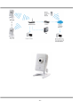
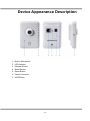
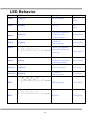
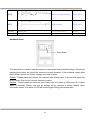
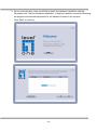
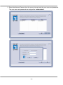
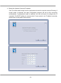
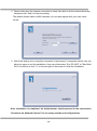
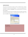
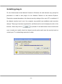
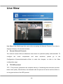
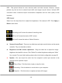
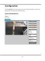
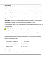
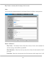
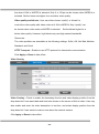
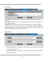
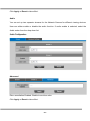
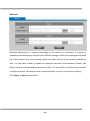
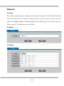
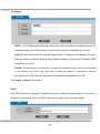
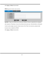
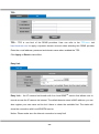
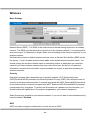
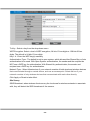
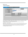
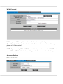
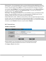
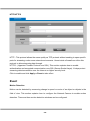
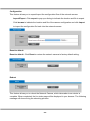
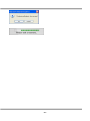
LevelOne User Manual WCS-0050 150Mbps Wireless Megapixel Network Camera Ver 1.0 Product name: 150Mbps Wireless Megapixel Network Camera (WCS-0050) Release Date: 2012/05/12 Manual Revision: V1.x Web site: www.level1.com Firmware 1.x.x.x Default Settings IP Address DHCP Username admin Password admin General Public License This product incorporates open source code into the software and therefore falls under the guidelines governed by the General Public License (GPL) agreement. Adhering to the GPL requirements, the open source code and open source license for the source code are available for free download at http://global.level1.com. If you would like a copy of the GPL or other open source code in this software on a physical CD medium, LevelOne (Digital Data Communications) offers to mail this CD to you upon request, for a price of US$9.99 plus the cost of shipping. - - Table of Contents Before You Use This Product ................................................................................ 0 Cube Network Camera Overview ........................................................................... 1 Device Appearance Description ............................................................................. 3 LED Behavior .................................................................................................. 4 Installation ...................................................................................................... 6 System Requirements ..........................................................................................................6 Camera Connection .............................................................................................................7 Software installation .............................................................................................................8 Access to the Network Camera ........................................................................... 15 Check Network Settings .....................................................................................................15 Add Password to prevent Unauthorized Access .................................................................15 Authentication ..................................................................................... 16 Installing plug-in .................................................................................................................17 Live View ...................................................................................................... 18 Configuration ............................................................................................... 21 Administrators can access the configuration page. .................................................... 21 Camera/Video/Audio ..........................................................................................................21 Camera ............................................................................................ 21 Video ............................................................................................... 23 Audio ............................................................................................... 27 Multicast .......................................................................................... 28 Network .............................................................................................................................29 IP Setting .......................................................................................... 29 UPnP ............................................................................................... 30 DDNS (dynamic domain name service) ...................................................... 31 TZO ................................................................................................. 32 Easy Link.......................................................................................... 32 Wireless .............................................................................................................................33 Basic Settings ................................................................................... 33 Security............................................................................................ 33 WEP ................................................................................................ 33 Site Survey ....................................................................................... 34 WPA-Personal ................................................................................... 35 WPA2-Personal .................................................................................. 36 Advanced Settings ............................................................................. 36 Wi-Fi Protected Setup.......................................................................... 37 - - HTTP/HTTPS ..................................................................................... 38 Event .................................................................................................................................38 Motion Detection ................................................................................ 38 Notification setting ............................................................................. 39 Scheduled Event ..............................................................................................................43 System Log ....................................................................................... 44 Date & Time Settings ........................................................................... 45 Device Information ............................................................................. 46 Maintenance .....................................................................................................................48 User Management............................................................................... 48 IP Filter ............................................................................................ 49 Firmware Upgrade .............................................................................. 49 Configuration .................................................................................... 50 Reset to default .................................................................................. 50 - - Before You Use This Product The use of surveillance devices may be prohibited by law in your country. The Network Camera is not only a high-performance web-ready camera but also can be part of a flexible surveillance system. It is the user’s responsibility to ensure that the operation of such devices is legal before installing this unit for its intended use. It is important to first verify that all contents received are complete according to the list in the "Package Contents" chapter. Take notice of the warnings in “Quick installation guide” before the Network Camera is installed, then carefully read and follow the instructions in the “Installation” chapter to avoid damages due to faulty assembly and installation. Package Contents Camera CD Manual/Utility QIG Camera Stand Power Adapter Cube Network Camera Overview Compact designed LevelOne WCS-0050 offers high video quality surveillance solution for residences and small businesses. Unlike general webcam, LevelOne WCS-0050 camera is a standalone complete system that does not need to be connected to a computer. The built-in web server allows user to access over local area network (LAN) and through the internet via a web browser for live viewing and intercom functions. Enhanced facility for user, live viewing can also be supported via 3GPP phone and MSN. Wireless capacity makes it easy to mount the device anywhere such as wall or desktop. 802.11b/g/n wireless with WPS and Ethernet connectivity can be integrated with an existing network environment. “Easy Installation Wizard” also allows user to configure device easily, even without IT background. Furthermore, the fashionable and streamline shape let the WCS-0050 not only a network camera, but also a decoration device. The WCS-0050 helps user monitor closely on family members, pets, offices, properties or anything valuables. -1- -2- Device Appearance Description 1. 2. 3. 4. 5. 6. 7. Built-in Microphone LED Indicator Ethernet Socket Stand Socket Reset Button Power Connector WPS Button -3- LED Behavior Function LED Behavior Description Remark Power Steady On Normal Operation Top (Blue) Power Power off Unlighted Top (Blue) 1. Connect to switch by Status Ethernet or WiFi. Steady On Second (Blue) 2. Reset to default. Status 1. Power off Unlighted 2. No connection Status Second (Blue) 1.While F/W upgrading 2.While WiFi site survey performing Second (Blue) 1.While network Status connection in progress Blinking Second (Blue) 2. Restoring settings. Internet Steady On Internet Unlighted Connect to Internet 1. Power off 2. No connection Third (Blue) Third (Blue) WPS WPS in progress Fourth (Blue) WPS WPS Error Fourth (Blue) -4- WPS Session overlap detected Fourth (Blue) WPS WPS Success Fourth (Blue) Privacy Steady On Privacy mask active Bottom Privacy Unlighted Privacy mask inactive Bottom Hardware Reset Reset Button The reset button is used to reset the system or restore the factory default settings. Sometimes resetting the system can return the camera to normal operation. If the problems remain after reset, please restore the factory settings and install it again. Reboot - Please press and release the indented reset button within 1 second with paper clip or thin object. Wait for the network camera to reboot. Restore - Please press and hold the reset button until the status of LED turns off. It takes about 10 seconds. Please note that all settings will be restored to factory default. Upon successful restore, the status of LED will be blue again during normal operation. -5- Installation System Requirements Operating System Microsoft Windows XP Home Edition SP2 Microsoft Windows XP Professional SP2 Computer IBM PC/AT Compatible CPU Pentium 3GHz or faster Memory 1024 MB or more Monitor 1024 x 768 pixels or more, 24-bit True color or better Network Interface 10/100Mbps Network interface card must be installed Web Browser Microsoft Internet Explorer 6.0 SP2 CD-ROM Drive It is necessary to read the operating instructions in the provided CD-ROM. Adobe Reader It is necessary to read the operating instructions in the provided CD-ROM. Audio function will not be working if a sound card is uninstalled on PC. Audio may be interrupted depending on the network environment. -6- Camera Connection Basic Connection 1. Connect the supplied power cable from the camera to the power outlet. 2. Connect the camera to a switch via Ethernet cable. Please check your product package contains all the accessories listed in the foregoing Package Contents. Upon powering up, the power LED will become lighted first and then the device will go through booting process. The status LED will be steady amber for getting IP address. After getting IP Address, the link LED will blink orange while network connection is processing. -7- Software installation In this manual, "User" refers to whoever has access to the Network Camera, and "Administrator" refers to the person who can configure the Network Camera and grant user access to the camera. After hardware connection checking, the users can run the Installation Wizard program included in the product CDROM to automatically search for the Network Camera in the Intranet. There may be many Network Cameras in the local network. Users can differentiate the Network Cameras with the serial number. The serial number is printed on the labels on the carton and the bottom of the Network Camera body. 1. Insert the Installation CD into the CD-ROM driver. Click install and shows the welcome screen. Follow the steps to install the Installation wizard on user’s computer. -8- -9- - 10 - 2. Do not check the box if user would like to check the hardware installation settings, Otherwise click “Skip the hardware installation” to skip the hardware connection checking, the program will automatically search for the Network Camera in the Intranet. Click “Start” to continue. - 11 - 3. Select the Network Camera from the survey list and enter the user name and password. The user name and password are assigned as “admin/admin”. - 12 - 4. Setting the Network Camera IP address User can either select simple mode or professional mode for network camera IP setting. If simple mode is selected, the easy configuration program will set up the connection automatically. If professional mode is selected, the user will need to configure the IP manually, The DHCP setting is recommended. If user wants to set IP address manually, please refer to the product user manual. - 13 - 5. Please make sure the internet connection is ready then start to do the internet discovery, otherwise click “Skip” to finish the setting. The default domain name is MAC address; you can also register with your own name on-line. 6. After finish setting, the connection successful or fail showed. If connection failed, user can either try again or quit the installation. User can either select “Run PC-NVR” or "Start Web GUI" to continue or click “X” on the top right of the screen to finish the installation. Once installation is completed, the Administrator should proceed to the next section "Access to the Network Camera" for necessary checks and configurations. - 14 - Access to the Network Camera Check Network Settings The Network Camera can be connected either before or immediately after software installation onto the Local Area Network. The Administrator should complete the network settings on the configuration page, including the correct subnet mask and IP address of gateway and DNS. Ask your network administrator or Internet service provider for the detail information. Add Password to prevent Unauthorized Access The Administrator should immediately implement a new password as a matter of prudent security practice. The user name and password for the Administrator are assigned as “admin/admin”. Once the Administrator’s password is saved, the Network Camera will ask for the user’s name and password before each access. The Administrator can set up a maximum of ten (10) user accounts. Each user can access the Network Camera except to perform system configuration. Once the password is changed, the browser will display an authentication window to ask for the new password. Once the password is set, there is no provision to recover the Administrator’s password. the original factory default settings. - 15 - The only option is to restore to Authentication After opening the Web browser and typing in the URL of the Network Camera, a dialogue window pops up to request a username and password. The user name and password for the Administrator are assigned as “admin/admin”. Upon successful authentication, the following figure is displayed. The foreground is the login window and the background shows the message if authentication fails. The user may check the option box to save the password for future convenience. This option is not available to the Administrator for obvious reason. - 16 - Installing plug-in For the initial access to the Network Camera in Windows, the web browser may prompt for permission to install a new plug-in for the Network Camera on the Internet Explorer. Permission request depends on the Internet security settings of the user’s PC or notebook. If the highest security level is set, the computer may prohibit any installation and execution attempt. This plug-in has been registered for certificate and is used to display the video in the browser. Users may click on to proceed. If the web browser does not allow the user to continue to install, check the Internet security option and lower the security levels or contact your IT or networking supervisor for help. - 17 - Live View Live View is the default page that opens when accessing the Network Camera. Live video is displayed directly in the browser window. Stream1/Stream2 Channels The network camera offers simultaneous dual stream for optimized quality and bandwidth. To configure the codec compression and video resolution, please go to the Configuration->Camera/video/audio->Video to make the changes, or refer to the Video configuration page. TCP/UDP protocol TCP - This protocol guarantees the complete delivery of streaming data and thus provides better video quality. Nevertheless, the downside with this protocol is that its real-time effect is not as good as that of the UDP protocol. - 18 - UDP - This protocol allows for more real-time audio and video streams. However, network packets may be lost due to network burst traffic and images may be broken. Activate UDP connection when occasions require time-sensitive responses and the video quality is less important. LED Control Select from the drop-down list to adjust the brightness of the camera’s LED. Click Apply or Reset to take effect. / Recording on/off: shows the status of recording video / MIC on /off: shows the status of MIC volume. / MD on/off: shows the status of Motion Detection Camera Control Panel - There are two slider bars and eight control buttons on the remote controller. They are describe as below: Brightness and Mic volume adjustment - Drag the slider bar to adjust the image brightness level and Mic volume. Click “Default” for default brightness setting and “Mute” for no sound. For more Audio setting, please refer to the Audio configuration on page 22. Speaker –You can output the audio form the computer’s audio input terminal to the camera’s built-in speaker output. Play or Stop - Click this button to play or stop the video. Recording - Click this button to record video to your computer. Snapshot - Click this button to capture and save still images. - 19 - Digital Zoom - Click this button to enable the zoom operation. Mirror - horizontally reflect the display of the live video. Flip - vertically reflect the display of the live video. Real Size - click this button to view the object in real size. Press this button again to switch back to normal mode. Full Screen - Click this button to switch to full screen mode. Press “Esc” key to switch back to normal mode. Motion Detection Alert: Click this button to enable motion detection alert function. Mute: Turn off the sound Set Default - Reset to default settings NOTE - The <Video Control Panel> function has no effect on the recorded video. Whatever changes made to the <Video Control Panel> will not be applied to the recorded video. - 20 - Configuration Click Configuration on the main page to enter the camera setting pages. Note that only Administrators can access the configuration page. Camera/Video/Audio Camera - 21 - Camera Setting Brightness - Drag the slider bar to adjust the image brightness level, which ranges from -5 to +5. Contrast - Drag the slider bar to adjust the image contrast level, which ranges from -5 to +5. Sharpness - Drag the slider bar to adjust the image sharpness level, which ranges from -5 to +5. Saturation - Drag the slider bar to adjust the image saturation level, which ranges from -5 to +5. Environment - User can look for a place that best suits your needs, either outdoor or indoor. Flicker-Free - While flicker-free technology eliminates the problem of flicker, it can cause slight judder on fast moving images or blurring problems; fast scrolling text for example may blur. NOTE - The "Environment" setting adjusts the sampling rate of the camera sensor to achieve Flicker-free effect on the video. The sampling rate, however, may not work best with the frame rate chosen in the "Video" setting. For best recording experience, configure your IP camera to one of the following frame rates based on the Environment used: Environment / Flicker-Free -----------------------------------Outdoor or Indoor ( 50Hz ) Frame Rate ---------------------------------25, 10, 7, 5, 3, 2 Indoor ( 60 Hz ) 20, 10, 7, 5, 3, 2 Mirror and Flip Mirror - Enable to horizontally reflect the display of the live video. - 22 - Flip - Enable to vertically reflect the display of the live video. . Video You can set up two separate streams for the Network Camera for different viewing devices. Stream 1 & Stream 2 Video Codec - The Network Camera offers three choices of video codec standards for real-time viewing: H.264, MPEG-4 and MJPEG. Video Resolution - Select from the drop down list to choose the best resolution that fit your need. Frame Rate - Select from the drop down list of the frame rate, which ranges from 2 to 30 - 23 - fps when H.264 or MJPEG is selected. Only 3 to 15 fps can be chosen when MPEG-4 is selected. Set the frame rate higher for a smoother video quality. Video quality and bit rate - User can either choose “quality” or “bitrate” to control the video quality with video codec at H.264 or MPEG4. Only “quality” can be chosen when video codec at MJPEG is selected. Set the bitrate higher for a better video quality. However, high bitrate may cost high network bandwidth Resources. The video qualities are selectable at the following settings: SoSo, OK, Not Bad, Medium, Standard, and Good. HTTP Transport – Enable to use HTTP protocol for video/audio communication. Click Apply or Reset to take effect. Video Overlay Video Overlay - Check to enable the timestamp function and select display position from the drop-down list if user wants date and time to be shown on the screen of the live video. User may also enable and enter the video description in text box; and select display position from the drop-down list if user wants to make a note about the network camera. Click Apply or Reset to take effect. - 24 - NOTE - The video overlay only takes effect in stream 1. - 25 - RTSP Server To utilize RTSP authentication, make sure that you have set a password for the Network Camera first. RTSP (Real-Time Streaming Protocol) controls the delivery of streaming media. By default the port number is set to 554. Authentication - Depending on your network security requirements, the Network Camera provides two types of security settings for streaming via RTSP protocol: NONE and DIGEST. If DIGEST authentication is selected, user credentials are encrypted using MD5 algorithm, thus providing better protection against unauthorized access. Save file folder Recording folder path - The destination for saving the recording video files. Click browse to specify the saving path. Snapshot folder path - The destination for saving the snapshot files. Click browse to specify the saving path. - 26 - Click Apply or Reset to take effect. Audio You can set up two separate streams for the Network Camera for different viewing devices. User can either enable or disable the audio function. If audio enable is selected, select the Audio codec from the drop down list. Advanced Echo cancellation Enabled: Enable to avoid an echo. Click Apply or Reset to take effect. - 27 - Multicast Multicast addressing is a network technology for the delivery of information to a group of destinations simultaneously using the most efficient strategy to deliver the messages over each link of the network only once, creating copies only when the links to the multiple destinations split. You can either enable or disable the stream1or stream2 for the Network Camera. The default value for multicast address and port are 234.1.2.3 and 10000. Use different port number for different stream. Use default value is recommended if you are not sure how to setting. Click Apply or Reset to take effect. - 28 - Network IP Setting This section explains how to configure wired network connection for the Network Camera. There are several ways to setup the Network Camera over the Internet. The first way is to obtain an available dynamic IP address assigned by a DHCP server. The second way is to utilize a static IP. The third way is to use PPPoE. - 29 - DHCP - Get IP address automatically. Select this option to obtain an available dynamic IP address assigned by a DHCP server each time the camera is connected to the LAN. Static IP - Select this option to manually assign a static IP address to the Network Camera. Enter the static IP address, Subnet mask, Default Gateway, Primary and Secondary DNS provided by your ISP. PPPoE - (Point-to-point over Ethernet): Choose this connection type if you are connected to the Internet via a DSL Line. Note that to utilize this feature, it requires an account provided by your ISP. Enter the user name and password provided by your ISP. Click Apply or Reset to take effect. UPnP Only UPnP discovery supported. Enable this function to allow the user to search for devices of interest on the network. Enter the UPnP name as you wish to show on the intranet. - 30 - Click Apply or Reset to take effect. DDNS (dynamic domain name service) DynDNS - Enable the DDNS service allows your Network Camera, especially when assigned with a dynamic IP address, to have a fixed host and domain name. Note that before utilizing this function; please apply a dynamic domain account first. Enter the username, password and hostname when enabled the DDNS. Click Apply or Reset to take effect. - 31 - TZO TZO - TZO is one kind of the DDNS providers. User can refer to the TZO.com: visit http://www.tzo.com/ to apply a dynamic domain account when selecting this DDNS provider. Enter the e-mail address, password and domain name when enabled the TZO. Click Apply or Reset to take effect. Easy Link Easy Link – the IP camera had bundle with free Level1DNSTM service that allows user to remote access the IP camera via internet. The default domain name is MAC address, you can also register your own name on-line but it have to check the available first. The status will show the connection with Level1DNSTM service. Notice: Please make sure the internet connection is ready first! - 32 - Wireless Basic Settings Network Name (SSID) - The SSID is the network name shared among all points in a wireless network. The SSID must be identical for all devices in the wireless network. It is case-sensitive and can be up to 32 characters in length. Make sure this setting is the same for all points in your wireless network. Wireless devices have a default wireless network name or Service Set Identifier (SSID) set by the factory,. Level1 wireless products use Level1 as the default wireless network name. You should change the wireless network name to something unique to distinguish your wireless network from other wireless networks that may exist around you, but do not use personal information, because this information may be available for anyone to see when browsing for wireless networks. Security Encryption protects data transmitted over a wireless network. Wi-Fi Protected Access (WPA-Personal/WPA2-personal) and Wired Equivalent Privacy (WEP) offer different levels of security for wireless communication. A network encrypted with WPA-Personal/WPA2-personal is more secure than a network encrypted with WEP, because WPA-Personal/WPA2-personal uses dynamic key encryption. To protect the information as it passes over the airwaves, you should enable the highest level of encryption supported by your network equipment. Select the security method for your wireless network. If you do not want to use wireless security, keep the default, Disabled. WEP WEP is a basic encryption method that is not as secure as WPA. - 33 - Tx Key - Select a key from the drop-down menu. WEP Encryption: Select a level of WEP encryption, 64 bits 10 hex digits or 128 bits 26 hex digits. The default is 64 bits 10 hex digits. Key 1-4 - Enter the WEP key(s) manually Authentication Type - The default is set to open system, which allows either Shared Key or Auto authentication to be used. With Open System authentication, the sender and the recipient do NOT use a WEP key for authentication. With Shared Key authentication, the sender and recipient use a WEP key for authentication. Network Type - Select Infrastructure if your network consists of both wired and wireless devices that communicate through a central device, such as an access point. Select Ad-hoc if your network consists of only wireless devices that communicate with each other directly. Click Apply or Reset to take effect. Site Survey SSID Broadcast, when wireless clients survey the local area for wireless networks to associate with, they will detect the SSID broadcast of the camera. - 34 - WPA-Personal WPA supports two encryption methods, TKIP and AES, with dynamic encryption keys. Select the type of algorithm, TKIP or AES. The default is TKIP. Shared Key - Enter the key shared between the Router and the server keys. Enter a passphrase of 8-63 characters. Network Type - Select Infrastructure if your network consists of both wired and wireless devices that communicate through a central device, such as an access point. Select Ad-hoc if your network consists of only wireless devices that communicate with each other directly. Click Apply or Reset to take effect. - 35 - WPA2-Personal WPA2 supports AES encryption methods with dynamic encryption keys. Shared Key - Enter the key shared between the Router and the server keys. Enter a pass phrase of 8-63 characters. NOTE: If you are using WPA or WPA2, each device in your wireless network MUST use the same WPA or WPA2 method and shared key, or else the network will not function properly. Advanced Settings - 36 - Network Mode - From this drop-down menu, you can select the wireless standards running on your network. If you have both Wireless-B, Wireless-G and Wireless-N (2.4GHz) devices in your network, keep the default setting, Mixed. If you have both Wireless-B, Wireless-G devices in your network, select BG-Mixed. If you have only Wireless-B devices, select Wireless-B Only. If you have only Wireless-G devices, select Wireless-G Only. If you have only Wireless-N (2.4GHz) devices, select Wireless-N Only. Radio Band - The settings are available for the Auto-20/40MHz channel and Standard-20 MHz channel. The Auto-20/40MHz channel set up a network using the 20/40MHz band, and the Standard-20 MHz channel set up a network using the 20 MHz band. Enable WMM (802.1e QoS) - WMM is a wireless Quality of Service feature that improves quality for audio, video, and voice applications by prioritizing wireless traffic. To use this feature, your wireless client devices in your network must support Wireless WMM. If you would like to disable this feature, select Disabled. Otherwise, keep the default, Enabled. Wi-Fi Protected Setup Use this method if your client device has a Wi-Fi Protected Setup PIN number. 1. Enter the PIN number and SSID from the device in the field on the screen. Click Apply or Reset to take effect. - 37 - HTTP/HTTPS HTTP - This protocol allows the same quality as TCP protocol without needing to open specific ports for streaming under some network environments. Users inside a firewall can utilize this protocol to allow streaming data through. HTTPS - (Hypertext Transfer Protocol over SSL): This section explains how to enable authentication and encrypted communication over SSL (Secure Socket Layer). It helps protect streaming data transmission over the Internet on higher security level. Click to enable and click Apply or Reset to take effect. Event Motion Detection Motion can be detected by measuring change in speed or vector of an object or objects in the field of view. This section explains how to configure the Network Camera to enable motion detection. There are three motion detection windows can be configured. - 38 - Detection Setting - Select and enable the motion detection windows function. Easier to trigger event by higher the sensitivity value and lower the Threshold value. Notification - To react in response to particular events. A typical application is that when a motion is detected, the Network Camera sends buffered images to a FTP server, Samba, SMTP or HTTP as notifications. In this page, you can specify which notification messages will be sent when a trigger is activated. You can configure the Network Camera to send video streaming URL or video clips to your email address or FTP site. Click Apply or Reset to take effect. Notification setting When an event is triggered, you can specify what kind of action will be performed. You can - 39 - attach video clip to your email address, FTP site, samba or HTTP. FTP - File Transfer Protocol (FTP) is often used as an application component to automatically transfer files for program internal functions. Select to send the media files to a FTP server when a trigger is activated. Enter the FTP IP address or hostname; by default, the FTP port server is set to 21, enter account name and password to configure the setting. Click Apply or Reset to take effect. SMTP - Select to send the media files via Email when a trigger is activated. From - Enter the email address of the sender. To - Enter the email address of the recipient. Many recipients are separated by commas. My name - The title shown in the email. Subject - Enter the subject of the email. Attached - There are two choices of media types available: video streaming URL and video clip. SMTP Server and port number - Enter the server host name and port number of the email server. Authentication - Select the authentication type from the drop-down list. Email Account - Enter the user name of the email account if necessary. - 40 - Email Password - Enter the password of the email account if necessary. Click Apply or Reset to take effect. Samba - Select to send the network file system media files via network neighborhood when a trigger is activated. IP Address - Enter the IP address of the samba server. User Name - Enter the user name of the samba server. Password - Enter the password of the samba server. Workgroup - Enter the workgroup of the samba server. Share DIR - Enter the share DIR of the samba server. - 41 - Click Apply or Reset to take effect. HTTP - Select to send the media files to a HTTP server when a trigger is activated. URL - Enter the URL of the HTTP server. Message: Enter the message that informs you when a trigger is activated. - 42 - Scheduled Event Click New to open the recording setting page. In this page, you can define the recording schedule and recording capacity. Name - Enter a descriptive name for the recording setting. Event - Select from the drop-down menu for the recording or rebooting event. Time - Specify the recording duration. ■ Select the time for recording in 24-hr time format. End time must be more than start time. ■ Select the days on weekly basis. When completed, Click Add to have recording name appears in the recording list on the recording page. Select Enabled; the system begins recording and send recorded file to the Network Storage. To edit a recording setting; click Edit to modify. Upon the completion, click update to finish the modification. To remove a recording setting from the list, select a recording name from the list and then click Delete. Click New to add more events. - 43 - System System Log Log - To send a system log to the network camera when a trigger is activated. This page displays the system’s log in chronological order. The system log is stored in the Network Camera’s buffer area and will be overwritten when reaching a certain amount. Click Retrieve to retrieve the log, or click Save to file to save the file in the specify location. - 44 - Date & Time Settings Manual - The user enters the date and time manually. Clone from PC - Sync with computer time; click clone to synchronize the date and time of the Network Camera with the local computer. The read-only date and time of the PC is displayed as updated. NTP - Select to update the time with the NTP server on hourly, daily, weekly, or monthly basis. Time Zone - According to your local time zone, select one from the drop-down list. NTP Server 1 and Server 2 - Enter the address of the NTP server. Daylight Saving: Enable this option to retain the Daylight Saving Time changes automatically. Click Apply or Reset to take effect. - 45 - Device Information Video/Audio Setting - To view the entire video/audio setting information about the network camera. Network Setting - To view the entire network setting information about the network camera. - 46 - System Information - To view the entire system information about the network camera. - 47 - Maintenance User Management This section explains how to enable password protection and create multiple accounts. Privilege Setting - Enter the new user’s name and password. Select the privilege for new user account. Click Add to take effect. The administrator account name is “admin”, which is permanent and can not be deleted. Access rights are sorted as following (Viewer, Administrator and Remote Viewer). Only administrators can access the Configuration page. Viewers can access the main page for live viewing only. The privilege of Remote Viewer is same as viewer except TCP protocol can only be selected for live viewing page. Administrators can add up to 10 user accounts. Administrator also can change user’s access rights or delete user accounts. Select an existing account to modify and make necessary changes; then click Update or Delete to take effect. - 48 - IP Filter IP Filter - Enable the IP filter and set of allow or deny IP address range to server. Click Add to list to add the IP range to the IP filter list. Click Apply or Reset to take effect. Firmware Upgrade This feature allows you to upgrade the firmware on your Network Camera. It takes about few minutes to complete the process. Note that do not power off the Network Camera during the upgrade. Upgrade - Click Browse… and specify the firmware file. Click Upgrade. The Network Camera starts to upgrade and will reboot automatically when the upgrade completes. - 49 - Configuration This feature allows you to export/import the configuration files of the network camera. Import/Export - Click export to pop up a dialog to indicate the location and file to export. Click browse to indicate the location and file of the camera configuration and click import to import the configuration file back into the network camera. Reset to default Reset to default - Click Reset to restore the network camera to factory default setting. Reboot This feature allows you to reboot the Network Camera, which takes about one minute to complete. When completed, the live video page will be displayed in your browser. The following message will show during the rebooting process. - 50 - - 51 -