1
SUPER
®
SC747 CHASSIS
Series
SC747TQ-R1400B
SC747TQ-R1620B
SC747BTQ-R1K62B
USER’S MANUAL
1.0b
SC747 Chassis Manual
The information in this User’s Manual has been carefully reviewed and is believed to be accurate.
The vendor assumes no responsibility for any inaccuracies that may be contained in this document,
makes no commitment to update or to keep current the information in this manual, or to notify any
person or organization of the updates. Please Note: For the most up-to-date version of this
manual, please see our web site at www.supermicro.com.
Super Micro Computer, Inc. ("Supermicro") reserves the right to make changes to the product
described in this manual at any time and without notice. This product, including software and
documentation, is the property of Supermicro and/or its licensors, and is supplied only under a
license. Any use or reproduction of this product is not allowed, except as expressly permitted by
the terms of said license.
IN NO EVENT WILL SUPERMICRO BE LIABLE FOR DIRECT, INDIRECT, SPECIAL, INCIDENTAL,
SPECULATIVE OR CONSEQUENTIAL DAMAGES ARISING FROM THE USE OR INABILITY TO
USE THIS PRODUCT OR DOCUMENTATION, EVEN IF ADVISED OF THE POSSIBILITY OF
SUCH DAMAGES. IN PARTICULAR, SUPERMICRO SHALL NOT HAVE LIABILITY FOR ANY
HARDWARE, SOFTWARE, OR DATA STORED OR USED WITH THE PRODUCT, INCLUDING THE
COSTS OF REPAIRING, REPLACING, INTEGRATING, INSTALLING OR RECOVERING SUCH
HARDWARE, SOFTWARE, OR DATA.
Any disputes arising between manufacturer and customer shall be governed by the laws of Santa
Clara County in the State of California, USA. The State of California, County of Santa Clara shall
be the exclusive venue for the resolution of any such disputes. Super Micro's total liability for all
claims will not exceed the price paid for the hardware product.
California Best Management Practices Regulations for Perchlorate Materials: This Perchlorate
warning applies only to products containing CR (Manganese Dioxide) Lithium coin cells. “Perchlorate
Material-special handling may apply. See www.dtsc.ca.gov/hazardouswaste/perchlorate”
WARNING: Handling of lead solder materials used in this
product may expose you to lead, a chemical known to
the State of California to cause birth defects and other
reproductive harm.
Manual Revision 1.0b
Release Date: December 26, 2012
Unless you request and receive written permission from Super Micro Computer, Inc., you may not
copy any part of this document.
Information in this document is subject to change without notice. Other products and companies
referred to herein are trademarks or registered trademarks of their respective companies or mark
holders.
Copyright © 2012 by Super Micro Computer, Inc.
All rights reserved.
Printed in the United States of America
ii
Preface
Preface
About This Manual
This manual is written for professional system integrators and PC technicians. It
provides information for the installation and configuration of the SC747 4U chassis. Installation and maintenance should be performed by experienced technicians
only.
Supermicro's SC747 server/workstation chassis is truly industry's most powerful
high-performance server chassis. The SC747 offers eleven full-height, full-length
PCI-E expansion slots and four sets of 6-pin and 8-pin power connectors to support
up to four double-width GPU cards. The SC747 comes equipped with optimized
redundant high-efficiency (93%) Gold Level 1400W or 1620W Platinum Level
power supplies with PMBus support and optimized thermal solutions with four
hot-swappable cooling fans and two hot-swappable exhaust fans. In the case of
the SC747BTQ-R1K628B this chassis also supports the option for up to two additional external rear fans. All of these fans incorporate advanced fan speed controls
to accommodate the most demanding GPU applications. Its eight hot-swappable
SAS/SATA hard drives offer exceptional storage capacity, and three 5.25" storage
modules can rotate 90° to accommodate tower or rack-mounting configurations.
This document lists compatible parts available when this document was published.
Always refer to the our Web site for updates on supported parts and configurations.
iii
SC747 Chassis Manual
Manual Organization
Chapter 1 Introduction
The first chapter provides an overview of the main components included with this
chassis and describes the main features of the SC747 chassis. This chapter also
includes contact information.
Chapter 2 Standardized Warning Statements for AC Systems
This chapter lists warnings, cautions, and system safety. You should thoroughly
familiarize yourself with this chapter for a general overview of safety cautions that
should be followed before installing and servicing this chassis.
Chapter 3 Chassis Components
Refer here for details on this chassis model including the fans, bays, airflow shields,
and other components.
Chapter 4 System Interface
This chapter provides details on the system interface, which includes the functions
and information provided by the control panel on the chassis as well as other LEDs
located throughout the system.
Chapter 5 Chassis Setup and Maintenance
Chapter 5 features detailed information on this chassis. You should follow the
procedures given in this chapter when installing, removing, or reconfiguring your
chassis.
Chapter 6 Rack Installation
Refer to this chapter for detailed information on chassis rack installation. You should
follow the procedures given in this chapter when installing, removing or reconfiguring
your chassis into a rack environment.
iv
Preface
Appendices
This section lists compatible cables, power supply specifications, and compatible
backplanes. Not all compatible backplanes are listed. Refer to our Web site for the
latest compatible backplane information.
Appendix A Chassis Cables
Appendix B Power Supply Specifications
Appendix C SAS-747TQ Backplane Manual
Appendix D M35S and M35T1 Mobile Rack Specifications
Appendix E M35TQ Mobile Rack Specifications
v
SC747 Chassis Manual
Table of Contents
Preface........................................................................................................... iii
About This Manual.............................................................................................. iii
Manual Organization...........................................................................................iv
Appendices...........................................................................................................v
Chapter 1 Introduction...............................................................................1-1
1-1Overview.......................................................................................................... 1-1
1-2
Shipping List..................................................................................................... 1-1
1-3
Chassis Features............................................................................................. 1-2
CPU.................................................................................................................. 1-2
I/O Expansion Slots......................................................................................... 1-2
Peripheral Drives.............................................................................................. 1-2
Other Features................................................................................................. 1-2
Contacting Supermicro..................................................................................... 1-3
Chapter 2 Standardized Warning Statements for AC Systems............. 2-1
2-1
About Standardized Warning Statements........................................................ 2-1
Warning Definition............................................................................................ 2-1
Installation Instructions..................................................................................... 2-4
Circuit Breaker................................................................................................. 2-5
Power Disconnection Warning......................................................................... 2-6
Equipment Installation...................................................................................... 2-8
Restricted Area................................................................................................. 2-9
Battery Handling............................................................................................. 2-10
Redundant Power Supplies........................................................................... 2-12
Backplane Voltage......................................................................................... 2-13
Comply with Local and National Electrical Codes......................................... 2-14
Product Disposal............................................................................................ 2-15
Hot Swap Fan Warning.................................................................................. 2-16
Power Cable and AC Adapter ....................................................................... 2-18
Chapter 3 Chassis Components...............................................................3-1
3-1
Overview.......................................................................................................... 3-1
3-2
Components..................................................................................................... 3-1
Chassis............................................................................................................. 3-1
Backplane......................................................................................................... 3-1
Fans................................................................................................................. 3-1
Mounting Rails (optional)................................................................................. 3-1
vi
Preface
Power Supply................................................................................................... 3-2
3-3
Where to get Replacement Components......................................................... 3-2
Chapter 4 System Interface.......................................................................4-1
4-1Overview.......................................................................................................... 4-1
4-2
Control Panel Buttons...................................................................................... 4-2
4-3
Control Panel LEDs......................................................................................... 4-2
4-4
Drive Carrier LEDs........................................................................................... 4-4
SAS/SATA Drives............................................................................................. 4-4
Chapter 5 Chassis Setup and Maintenance............................................ 5-1
5-1Overview.......................................................................................................... 5-1
5-2
Installation and Maintenance........................................................................... 5-1
5-3
Chassis Covers................................................................................................ 5-2
Removing the Main Cover............................................................................... 5-3
Opening the Front Cover................................................................................. 5-4
5-4
Configuring the the Storage Module ............................................................... 5-5
Tower or Rack Configuration........................................................................... 5-5
Installing Drives in the Storage Module........................................................... 5-7
Adding Five Hard Drives Using a Supermicro Mobile Rack.......................... 5-12
5-5
Installing Hard Drives..................................................................................... 5-14
Installing Hard Drives into the Chassis.......................................................... 5-14
5-6
Installing the Motherboard............................................................................. 5-16
I/O Slot Shield Installation.............................................................................. 5-16
Permanent and Optional Standoffs................................................................ 5-17
Installing the Motherboard............................................................................. 5-18
Installing the Active Heatsink......................................................................... 5-19
Power Supply Connections............................................................................ 5-20
Configuring the Expansion Slots.................................................................... 5-21
Installing Double-Width Graphics Cards........................................................ 5-23
5-7
System Fans.................................................................................................. 5-25
Replacing Mid-Chassis System Fans............................................................ 5-25
Replacing Rear Exhaust Fans....................................................................... 5-26
Adding Optional External Rear Fans (BTQ Model Only)............................... 5-27
5-8
Power Supply ................................................................................................ 5-30
Replacing the Power Supply.......................................................................... 5-30
vii
SC747 Chassis Manual
Rack Precautions............................................................................................. 6-2
Rack Mounting Considerations........................................................................ 6-2
Removing the Chassis Cover and Feet........................................................... 6-4
Installing the Chassis Handles and Inner Rails............................................... 6-7
Installing the Outer Rails to the Rack.............................................................. 6-8
Installing the Chassis into a Rack................................................................... 6-9
Installing the Chassis Cover.......................................................................... 6-10
Installing Feet on the Chassis........................................................................6-11
Appendix A SC747 Chassis Cables......................................................... A-1
Appendix B SC747 Power Supply Specifications.................................. B-1
Appendix C SAS-747TQ Backplane Specifications............................... C-1
Appendix D M35T1 Mobile Rack Specifications.................................... D-1
Appendix E M35TQ Mobile Rack Specificaitons.....................................E-1
viii
Chapter 1: Introduction
Chapter 1
Introduction
1-1Overview
Supermicro’s SC747 4U chassis features a unique and highly-optimized design.
The chassis is equipped with a high-efficiency power supply. High-performance fans
provide ample optimized cooling for the system and eight hot-swappable drive bays
offer maximum storage capacity in a 4U form factor.
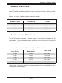
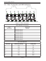
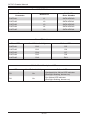
1-2 Shipping List
Please visit the following link for the latest shipping lists and part numbers for your
particular chassis model http://www.supermicro.com/products/chassis/4U/?chs=747.
SC747 Chassis
CPU
HDD
I/O Slots
Power
Supply
SC747TQ-R1400B
DP/UP
8x SAS/SATA
11x FF
1400W Redundant
(Gold Level)
SC747TQ-R1620B
DP/UP
8x SAS/SATA
11x FF
1620W Redundant
(Gold Level)
SC747BTQ-R1K62B
DP/UP
8x SAS/SATA
11x FF
1620W Redundant
(Gold Level)
Model
Legend
UP = Single Processor Support
DP = Dual Processor Support
FF = Full-height, Full-length
1-1
SC747 Chassis Manual
1-3 Chassis Features
The SC747 4U high-performance chassis includes the following features:
CPU
The SC747 chassis supports single or dual processors.
Hard Drives
The SC747 chassis features eight slots for SAS/SATA drives. These drives are hot
-swappable. Once set up correctly, these drives can be removed without powering
down the server.
I/O Expansion Slots
Each version of the SC747 chassis includes eleven (TQ model) or nine (TG model)
full-height PCI slots for expansion cards.
Peripheral Drives
Each SC747 chassis provides three 5.25” peripheral drive bays for DVD-ROM/DVDRW drives, or additional hard drives.These bays are in a rotating cage that allows
for the chassis to be configured in both tower and rack mounted environments.
Other Features
Other on-board features are included to promote system health. These include four
cooling fans, two exhaust fans, a convenient power switch, reset button, and five
LED indicators.
1-2
Chapter 1 Introduction
1-4 Contacting Supermicro
Headquarters
Address:
Super Micro Computer, Inc.
980 Rock Ave.
San Jose, CA 95131 U.S.A.
Tel:
+1 (408) 503-8000
Fax:
+1 (408) 503-8008
Email:
[email protected] (General Information)
[email protected] (Technical Support)
Web Site:
www.supermicro.com
Europe
Address:
Super Micro Computer B.V.
Het Sterrenbeeld 28, 5215 ML
's-Hertogenbosch, The Netherlands
Tel:
+31 (0) 73-6400390
Fax:
+31 (0) 73-6416525
Email:
[email protected] (General Information)
[email protected] (Technical Support)
[email protected] (Customer Support)
Asia-Pacific
Address:
Super Micro Computer, Inc.
4F, No. 232-1, Liancheng Rd
Chung-Ho Dist., New Taipei City 235
Taiwan
Tel:
+886-(2) 8226-3990
Fax:
+886-(2) 8226-3991
Web Site:
www.supermicro.com.tw
Technical Support:
Email:
[email protected]
Tel: +886-(2)-8226-3990
1-3
SC747 Chassis Manual
Notes
1-4
Chapter 2: Warning Statements for AC Systems
Chapter 2
Standardized Warning Statements for AC Systems
2-1 About Standardized Warning Statements
The following statements are industry standard warnings, provided to warn the user
of situations which have the potential for bodily injury. Should you have questions
or experience difficulty, contact Supermicro's Technical Support department
for assistance. Only certified technicians should attempt to install or configure
components.
Read this appendix in its entirety before installing or configuring components in the
Supermicro chassis.
These warnings may also be found on our web site at http://www.supermicro.com/
about/policies/safety_information.cfm.
Warning Definition
Warning!
This warning symbol means danger. You are in a situation that could cause bodily
injury. Before you work on any equipment, be aware of the hazards involved with
electrical circuitry and be familiar with standard practices for preventing accidents.
警告の定義
この警告サインは危険を意味します。
人身事故につながる可能性がありますので、いずれの機器でも動作させる前に、
電気回路に含まれる危険性に注意して、標準的な事故防止策に精通して下さい。
此警告符号代表危险。
您正处于可能受到严重伤害的工作环境中。在您使用设备开始工作之前,必须充分
意识到触电的危险,并熟练掌握防止事故发生的标准工作程序。请根据每项警告结
尾的声明号码找到此设备的安全性警告说明的翻译文本。
此警告符號代表危險。
您正處於可能身體可能會受損傷的工作環境中。在您使用任何設備之前,請注意觸
電的危險,並且要熟悉預防事故發生的標準工作程序。請依照每一注意事項後的號
碼找到相關的翻譯說明內容。
2-1
SC216 Chassis Manual
Warnung
WICHTIGE SICHERHEITSHINWEISE
Dieses Warnsymbol bedeutet Gefahr. Sie befinden sich in einer Situation, die zu
Verletzungen führen kann. Machen Sie sich vor der Arbeit mit Geräten mit den
Gefahren elektrischer Schaltungen und den üblichen Verfahren zur Vorbeugung
vor Unfällen vertraut. Suchen Sie mit der am Ende jeder Warnung angegebenen
Anweisungsnummer nach der jeweiligen Übersetzung in den übersetzten
Sicherheitshinweisen, die zusammen mit diesem Gerät ausgeliefert wurden.
BEWAHREN SIE DIESE HINWEISE GUT AUF.
INSTRUCCIONES IMPORTANTES DE SEGURIDAD
Este símbolo de aviso indica peligro. Existe riesgo para su integridad física. Antes
de manipular cualquier equipo, considere los riesgos de la corriente eléctrica y
familiarícese con los procedimientos estándar de prevención de accidentes. Al
final de cada advertencia encontrará el número que le ayudará a encontrar el texto
traducido en el apartado de traducciones que acompaña a este dispositivo.
GUARDE ESTAS INSTRUCCIONES.
IMPORTANTES INFORMATIONS DE SÉCURITÉ
Ce symbole d'avertissement indique un danger. Vous vous trouvez dans une
situation pouvant entraîner des blessures ou des dommages corporels. Avant
de travailler sur un équipement, soyez conscient des dangers liés aux circuits
électriques et familiarisez-vous avec les procédures couramment utilisées pour
éviter les accidents. Pour prendre connaissance des traductions des avertissements
figurant dans les consignes de sécurité traduites qui accompagnent cet appareil,
référez-vous au numéro de l'instruction situé à la fin de chaque avertissement.
CONSERVEZ CES INFORMATIONS.
תקנון הצהרות אזהרה
על מנת להזהיר את המשתמש מפני חבלה,הצהרות הבאות הן אזהרות על פי תקני התעשייה
יש ליצור קשר עם מחלקת תמיכה, במידה ויש שאלות או היתקלות בבעיה כלשהי.פיזית אפשרית
. טכנאים מוסמכים בלבד רשאים להתקין או להגדיר את הרכיבים.טכנית של סופרמיקרו
.יש לקרוא את הנספח במלואו לפני התקנת או הגדרת הרכיבים במארזי סופרמיקרו
2-2
Warning Statements for AC Systems
. تحذٌز!هذا الزهز ٌعًٌ خطز اًك فً حالة ٌوكي أى تتسبب فً اصابة جسذٌة
كي على علن بالوخاطز الٌاجوة عي الذوائز،قبل أى تعول على أي هعذات
الكهزبائٍة
وكي على دراٌة بالووارسات الىقائٍة لوٌع وقىع أي حىادث
استخذم رقن البٍاى الوٌصىص فً ًهاٌة كل تحذٌز للعثىر تزجوتها
안전을 위한 주의사항
경고!
이 경고 기호는 위험이 있음을 알려 줍니다. 작업자의 신체에 부상을 야기 할 수
있는 상태에 있게 됩니다. 모든 장비에 대한 작업을 수행하기 전에 전기회로와
관련된 위험요소들을 확인하시고 사전에 사고를 방지할 수 있도록 표준
작업절차를 준수해 주시기 바랍니다.
해당 번역문을 찾기 위해 각 경고의 마지막 부분에 제공된 경고문 번호를
참조하십시오
BELANGRIJKE VEILIGHEIDSINSTRUCTIES
Dit waarschuwings symbool betekent gevaar. U verkeert in een situatie die
lichamelijk letsel kan veroorzaken. Voordat u aan enige apparatuur gaat werken,
dient u zich bewust te zijn van de bij een elektrische installatie betrokken risico's
en dient u op de hoogte te zijn van de standaard procedures om ongelukken te
voorkomen. Gebruik de nummers aan het eind van elke waarschuwing om deze te
herleiden naar de desbetreffende locatie.
BEWAAR DEZE INSTRUCTIES
2-3
SC216 Chassis Manual
Installation Instructions
Warning!
Read the installation instructions before connecting the system to the power source.
設置手順書
システムを電源に接続する前に、設置手順書をお読み下さい。
警告
将此系统连接电源前,请先阅读安装说明。
警告
將系統與電源連接前,請先閱讀安裝說明。
Warnung
Vor dem Anschließen des Systems an die Stromquelle die Installationsanweisungen
lesen.
¡Advertencia!
Lea las instrucciones de instalación antes de conectar el sistema a la red de
alimentación.
Attention
Avant de brancher le système sur la source d'alimentation, consulter les directives
d'installation.
.יש לקרוא את הוראות התקנה לפני חיבור המערכת למקור מתח
اقر إرشادات التركيب قبل توصيل النظام إلى مصدر للطاقة
시스템을 전원에 연결하기 전에 설치 안내를 읽어주십시오.
Waarschuwing
Raadpleeg de installatie-instructies voordat u het systeem op de voedingsbron
aansluit.
2-4
Chapter 2: Warning Statements for AC Systems
Circuit Breaker
Warning!
This product relies on the building's installation for short-circuit (overcurrent)
protection. Ensure that the protective device is rated not greater than: 250 V, 20 A.
サーキット・ブレーカー
この製品は、短絡(過電流)保護装置がある建物での設置を前提としています。
保護装置の定格が250 V、20 Aを超えないことを確認下さい。
警告
此产品的短路(过载电流)保护由建筑物的供电系统提供,确保短路保护设备的额定电
流不大于250V,20A。
警告
此產品的短路(過載電流)保護由建築物的供電系統提供,確保短路保護設備的額定電
流不大於250V,20A。
Warnung
Dieses Produkt ist darauf angewiesen, dass im Gebäude ein Kurzschlussbzw. Überstromschutz installiert ist. Stellen Sie sicher, dass der Nennwert der
Schutzvorrichtung nicht mehr als: 250 V, 20 A beträgt.
¡Advertencia!
Este equipo utiliza el sistema de protección contra cortocircuitos (o sobrecorrientes)
del edificio. Asegúrese de que el dispositivo de protección no sea superior a: 250
V, 20 A.
Attention
Pour ce qui est de la protection contre les courts-circuits (surtension), ce produit
dépend de l'installation électrique du local. Vérifiez que le courant nominal du
dispositif de protection n'est pas supérieur à :250 V, 20 A.
יש לוודא כי.מוצר זה מסתמך על הגנה המותקנת במבנים למניעת קצר חשמלי
250 V, 20 A-המכשיר המגן מפני הקצר החשמלי הוא לא יותר מ
هذا المنتج يعتمد على معداث الحمايت مه الدوائرالقصيرة التي تم تثبيتها في
المبنى
20A, 250V :تأكد من أن تقييم الجهاز الوقائي ليس أكثر من
2-5
SC216 Chassis Manual
경고!
이 제품은 전원의 단락(과전류)방지에 대해서 전적으로 건물의 관련 설비에
의존합니다. 보호장치의 정격이 반드시 250V(볼트), 20A(암페어)를 초과하지
않도록 해야 합니다.
Waarschuwing
Dit product is afhankelijk van de kortsluitbeveiliging (overspanning) van
uw electrische installatie. Controleer of het beveiligde aparaat niet groter
gedimensioneerd is dan 220V, 20A.
Power Disconnection Warning
Warning!
The system must be disconnected from all sources of power and the power cord
removed from the power supply module(s) before accessing the chassis interior to
install or remove system components.
電源切断の警告
システムコンポーネントの取り付けまたは取り外しのために、
シャーシー内部にアクセス
するには、
システムの電源はすべてのソースから切断され、電源コードは電源モジュールから取り
外す必要があります。
警告
在你打开机箱并安装或移除内部器件前,必须将系统完全断电,并移除电源线。
警告
在您打開機殼安裝或移除內部元件前,必須將系統完全斷電,並移除電源線。
Warnung
Das System muss von allen Quellen der Energie und vom Netzanschlusskabel
getrennt sein, das von den Spg.Versorgungsteilmodulen entfernt wird, bevor es
auf den Chassisinnenraum zurückgreift, um Systemsbestandteile anzubringen oder
zu entfernen.
2-6
Chapter 2: Warning Statements for AC Systems
¡Advertencia!
El sistema debe ser disconnected de todas las fuentes de energía y del cable
eléctrico quitado de los módulos de fuente de alimentación antes de tener acceso
el interior del chasis para instalar o para quitar componentes de sistema.
Attention
Le système doit être débranché de toutes les sources de puissance ainsi que de
son cordon d'alimentation secteur avant d'accéder à l'intérieur du chassis pour
installer ou enlever des composants de systéme.
אזהרה מפני ניתוק חשמלי
!אזהרה
יש לנתק את המערכת מכל מקורות החשמל ויש להסיר את כבל החשמלי מהספק
.לפני גישה לחלק הפנימי של המארז לצורך התקנת או הסרת רכיבים
يجب فصم اننظاو من جميع مصادر انطاقت وإزانت سهك انكهرباء من وحدة امداد
انطاقت قبم
انىصىل إنى انمناطق انداخهيت نههيكم نتثبيج أو إزانت مكىناث الجهاز
경고!
시스템에 부품들을 장착하거나 제거하기 위해서는 섀시 내부에 접근하기 전에
반드시 전원 공급장치로부터 연결되어있는 모든 전원과 전기코드를 분리해주어야
합니다.
Waarschuwing
Voordat u toegang neemt tot het binnenwerk van de behuizing voor het installeren
of verwijderen van systeem onderdelen, dient u alle spanningsbronnen en alle
stroomkabels aangesloten op de voeding(en) van de behuizing te verwijderen
2-7
SC216 Chassis Manual
Equipment Installation
Warning!
Only trained and qualified personnel should be allowed to install, replace, or service
this equipment.
機器の設置
トレーニングを受け認定された人だけがこの装置の設置、交換、
またはサービスを許可
されています。
警告
只有经过培训且具有资格的人员才能进行此设备的安装、更换和维修。
警告
只有經過受訓且具資格人員才可安裝、更換與維修此設備。
Warnung
Das Installieren, Ersetzen oder Bedienen dieser Ausrüstung sollte nur geschultem,
qualifiziertem Personal gestattet werden.
¡Advertencia!
Solamente el personal calificado debe instalar, reemplazar o utilizar este equipo.
Attention
Il est vivement recommandé de confier l'installation, le remplacement et la
maintenance de ces équipements à des personnels qualifiés et expérimentés.
!אזהרה
. להחליף את הציוד או לתת שירות עבור הציוד,צוות מוסמך בלבד רשאי להתקין
يجب أن يسمح فقط للمىظفيه المؤهليه والمدربيه لتزكيب واستبدال أو خدمة هذا الجهاس
경고!
훈련을 받고 공인된 기술자만이 이 장비의 설치, 교체 또는 서비스를 수행할 수
있습니다.
2-8
Chapter 2: Warning Statements for AC Systems
Waarschuwing
Deze apparatuur mag alleen worden geïnstalleerd, vervangen of hersteld door
geschoold en gekwalificeerd personeel.
Restricted Area
Warning!
This unit is intended for installation in restricted access areas. A restricted access
area can be accessed only through the use of a special tool, lock and key, or other
means of security. (This warning does not apply to workstations).
アクセス制限区域
このユニットは、
アクセス制限区域に設置されることを想定しています。
アクセス制限区域は、特別なツール、鍵と錠前、その他のセキュリティの手段を用いての
み出入りが可能です。
警告
此部件应安装在限制进出的场所,限制进出的场所指只能通过使用特殊工具、锁和
钥匙或其它安全手段进出的场所。
警告
此裝置僅限安裝於進出管制區域,進出管制區域係指僅能以特殊工具、鎖頭及鑰匙
或其他安全方式才能進入的區域。
Warnung
Diese Einheit ist zur Installation in Bereichen mit beschränktem Zutritt vorgesehen.
Der Zutritt zu derartigen Bereichen ist nur mit einem Spezialwerkzeug, Schloss und
Schlüssel oder einer sonstigen Sicherheitsvorkehrung möglich.
¡Advertencia!
Esta unidad ha sido diseñada para instalación en áreas de acceso restringido.
Sólo puede obtenerse acceso a una de estas áreas mediante la utilización de una
herramienta especial, cerradura con llave u otro medio de seguridad.
Attention
Cet appareil doit être installée dans des zones d'accès réservés. L'accès à une
zone d'accès réservé n'est possible qu'en utilisant un outil spécial, un mécanisme
de verrouillage et une clé, ou tout autre moyen de sécurité.
2-9
SC216 Chassis Manual
אזור עם גישה מוגבלת
!אזהרה
הגישה ניתנת בעזרת.יש להתקין את היחידה באזורים שיש בהם הגבלת גישה
.)' מנעול וכד,כלי אבטחה בלבד (מפתח
. تم تخصيص هذه انىحذة نتركُبها فٍ مناطق محظورة
،َمكن انىصىل إنً منطقت محظورة فقط من خالل استخذاو أداة خاصت
قفم ومفتاح أو أٌ وسُهت أخري نالمألما
경고!
이 장치는 접근이 제한된 구역에 설치하도록 되어있습니다. 특수도구, 잠금 장치 및
키, 또는 기타 보안 수단을 통해서만 접근 제한 구역에 들어갈 수 있습니다.
Waarschuwing
Dit apparaat is bedoeld voor installatie in gebieden met een beperkte toegang.
Toegang tot dergelijke gebieden kunnen alleen verkregen worden door gebruik te
maken van speciaal gereedschap, slot en sleutel of andere veiligheidsmaatregelen.
Battery Handling
Warning!
There is the danger of explosion if the battery is replaced incorrectly. Replace the
battery only with the same or equivalent type recommended by the manufacturer.
Dispose of used batteries according to the manufacturer's instructions
電池の取り扱い
電池交換が正しく行われなかった場合、破裂の危険性があります。交換する電池はメー
カーが推奨する型、
または同等のものを使用下さい。使用済電池は製造元の指示に従
って処分して下さい。
警告
电池更换不当会有爆炸危险。请只使用同类电池或制造商推荐的功能相当的电池更
换原有电池。请按制造商的说明处理废旧电池。
警告
電池更換不當會有爆炸危險。請使用製造商建議之相同或功能相當的電池更換原有
電池。請按照製造商的說明指示處理廢棄舊電池。
2-10
Chapter 2: Warning Statements for AC Systems
Warnung
Bei Einsetzen einer falschen Batterie besteht Explosionsgefahr. Ersetzen Sie die
Batterie nur durch den gleichen oder vom Hersteller empfohlenen Batterietyp.
Entsorgen Sie die benutzten Batterien nach den Anweisungen des Herstellers.
Attention
Danger d'explosion si la pile n'est pas remplacée correctement. Ne la remplacer
que par une pile de type semblable ou équivalent, recommandée par le fabricant.
Jeter les piles usagées conformément aux instructions du fabricant.
¡Advertencia!
Existe peligro de explosión si la batería se reemplaza de manera incorrecta.
Reemplazar la batería exclusivamente con el mismo tipo o el equivalente
recomendado por el fabricante. Desechar las baterías gastadas según las
instrucciones del fabricante.
!אזהרה
יש להחליף.קיימת סכנת פיצוץ של הסוללה במידה והוחלפה בדרך לא תקינה
.את הסוללה בסוג התואם מחברת יצרן מומלצת
.סילוק הסוללות המשומשות יש לבצע לפי הוראות היצרן
هناك خطر من انفجار في حالة اسحبذال البطارية بطريقة غير صحيحة فعليل
اسحبذال البطارية
فقط بنفس النىع أو ما يعادلها مما أوصث به الشرمة المصنعة
جخلص من البطاريات المسحعملة وفقا لحعليمات الشرمة الصانعة
경고!
배터리가 올바르게 교체되지 않으면 폭발의 위험이 있습니다. 기존 배터리와
동일하거나 제조사에서 권장하는 동등한 종류의 배터리로만 교체해야 합니다.
제조사의 안내에 따라 사용된 배터리를 처리하여 주십시오.
Waarschuwing
Er is ontploffingsgevaar indien de batterij verkeerd vervangen wordt. Vervang de
batterij slechts met hetzelfde of een equivalent type die door de fabrikant aanbevolen
wordt. Gebruikte batterijen dienen overeenkomstig fabrieksvoorschriften afgevoerd
te worden.
2-11
SC216 Chassis Manual
Redundant Power Supplies
Warning!
This unit might have more than one power supply connection. All connections must
be removed to de-energize the unit.
冗長電源装置
このユニットは複数の電源装置が接続されている場合があります。
ユニットの電源を切るためには、すべての接続を取り外さなければなりません。
警告
此部件连接的电源可能不止一个,必须将所有电源断开才能停止给该部件供电。
警告
此裝置連接的電源可能不只一個,必須切斷所有電源才能停止對該裝置的供電。
Warnung
Dieses Gerät kann mehr als eine Stromzufuhr haben. Um sicherzustellen, dass
der Einheit kein trom zugeführt wird, müssen alle Verbindungen entfernt werden.
¡Advertencia!
Puede que esta unidad tenga más de una conexión para fuentes de alimentación.
Para cortar por completo el suministro de energía, deben desconectarse todas las
conexiones.
Attention
Cette unité peut avoir plus d'une connexion d'alimentation. Pour supprimer toute
tension et tout courant électrique de l'unité, toutes les connexions d'alimentation
doivent être débranchées.
אם קיים יותר מספק אחד
!אזהרה
יש להסיר את כל החיבורים על מנת לרוקן.ליחדה יש יותר מחיבור אחד של ספק
.את היחידה
2-12
Chapter 2: Warning Statements for AC Systems
경고!
.قد يكون لهذا الجهاز عدة اتصاالت بوحدات امداد الطاقة
يجب إزالة كافة االتصاالت لعسل الوحدة عن الكهرباء
이 장치에는 한 개 이상의 전원 공급 단자가 연결되어 있을 수 있습니다. 이 장치에
전원을 차단하기 위해서는 모든 연결 단자를 제거해야만 합니다.
Waarschuwing
Deze eenheid kan meer dan één stroomtoevoeraansluiting bevatten. Alle
aansluitingen dienen verwijderd te worden om het apparaat stroomloos te maken.
Backplane Voltage
Warning!
Hazardous voltage or energy is present on the backplane when the system is
operating. Use caution when servicing.
バックプレーンの電圧
システムの稼働中は危険な電圧または電力が、バックプレーン上にかかっています。
修理する際には注意ください。
警告
当系统正在进行时,背板上有很危险的电压或能量,进行维修时务必小心。
警告
當系統正在進行時,背板上有危險的電壓或能量,進行維修時務必小心。
Warnung
Wenn das System in Betrieb ist, treten auf der Rückwandplatine gefährliche
Spannungen oder Energien auf. Vorsicht bei der Wartung.
¡Advertencia!
Cuando el sistema está en funcionamiento, el voltaje del plano trasero es peligroso.
Tenga cuidado cuando lo revise.
Attention
Lorsque le système est en fonctionnement, des tensions électriques circulent sur
le fond de panier. Prendre des précautions lors de la maintenance.
2-13
SC216 Chassis Manual
מתח בפנל האחורי
!אזהרה
יש להיזהר במהלך.קיימת סכנת מתח בפנל האחורי בזמן תפעול המערכת
.העבודה
هناك خطز مه التيار الكهزبائي أوالطاقة المىجىدة على اللىحة
عندما يكىن النظام يعمل كه حذرا عند خدمة هذا الجهاس
경고!
시스템이 동작 중일 때 후면판 (Backplane)에는 위험한 전압이나 에너지가 발생
합니다. 서비스 작업 시 주의하십시오.
Waarschuwing
Een gevaarlijke spanning of energie is aanwezig op de backplane wanneer het
systeem in gebruik is. Voorzichtigheid is geboden tijdens het onderhoud.
Comply with Local and National Electrical Codes
Warning!
Installation of the equipment must comply with local and national electrical codes.
地方および国の電気規格に準拠
機器の取り付けはその地方および国の電気規格に準拠する必要があります。
警告
设备安装必须符合本地与本国电气法规。
警告
設備安裝必須符合本地與本國電氣法規。
Warnung
Die Installation der Geräte muss den Sicherheitsstandards entsprechen.
¡Advertencia!
La instalacion del equipo debe cumplir con las normas de electricidad locales y
nacionales.
2-14
Chapter 2: Warning Statements for AC Systems
Attention
L'équipement doit être installé conformément aux normes électriques nationales
et locales.
תיאום חוקי החשמל הארצי
!אזהרה
.התקנת הציוד חייבת להיות תואמת לחוקי החשמל המקומיים והארציים
تركيب المعدات الكهربائية يجب أن يمتثل للقىاويه المحلية والىطىية المتعلقة
بالكهرباء
경고!
현 지역 및 국가의 전기 규정에 따라 장비를 설치해야 합니다.
Waarschuwing
Bij installatie van de apparatuur moet worden voldaan aan de lokale en nationale
elektriciteitsvoorschriften.
Product Disposal
Warning!
Ultimate disposal of this product should be handled according to all national laws
and regulations.
製品の廃棄
この製品を廃棄処分する場合、国の関係する全ての法律・条例に従い処理する必要が
あります。
警告
本产品的废弃处理应根据所有国家的法律和规章进行。
警告
本產品的廢棄處理應根據所有國家的法律和規章進行。
Warnung
Die Entsorgung dieses Produkts sollte gemäß allen Bestimmungen und Gesetzen
des Landes erfolgen.
2-15
SC216 Chassis Manual
¡Advertencia!
Al deshacerse por completo de este producto debe seguir todas las leyes y
reglamentos nacionales.
Attention
La mise au rebut ou le recyclage de ce produit sont généralement soumis à des
lois et/ou directives de respect de l'environnement. Renseignez-vous auprès de
l'organisme compétent.
סילוק המוצר
!אזהרה
.סילוק סופי של מוצר זה חייב להיות בהתאם להנחיות וחוקי המדינה
عند التخلص النهائي من هذا المنتج ينبغي التعامل معه وفقا لجميع القىانين واللىائح الىطنية
경고!
이 제품은 해당 국가의 관련 법규 및 규정에 따라 폐기되어야 합니다.
Waarschuwing
De uiteindelijke verwijdering van dit product dient te geschieden in overeenstemming
met alle nationale wetten en reglementen.
Hot Swap Fan Warning
Warning!
The fans might still be turning when you remove the fan assembly from the chassis.
Keep fingers, screwdrivers, and other objects away from the openings in the fan
assembly's housing.
ファン・ホットスワップの警告
シャーシから冷却ファン装置を取り外した際、
ファンがまだ回転している可能性がありま
す。ファンの開口部に、指、
ドライバー、およびその他のものを近づけないで下さい。
警告
当您从机架移除风扇装置,风扇可能仍在转动。小心不要将手指、螺丝起子和其他
物品太靠近风扇
2-16
Chapter 2: Warning Statements for AC Systems
警告
當您從機架移除風扇裝置,風扇可能仍在轉動。小心不要將手指、螺絲起子和其他
物品太靠近風扇。
Warnung
Die Lüfter drehen sich u. U. noch, wenn die Lüfterbaugruppe aus dem Chassis
genommen wird. Halten Sie Finger, Schraubendreher und andere Gegenstände
von den Öffnungen des Lüftergehäuses entfernt.
¡Advertencia!
Los ventiladores podran dar vuelta cuando usted quite ell montaje del ventilador
del chasis. Mandtenga los dedos, los destornilladores y todos los objetos lejos de
las aberturas del ventilador
Attention
Il est possible que les ventilateurs soient toujours en rotation lorsque vous retirerez
le bloc ventilateur du châssis. Prenez garde à ce que doigts, tournevis et autres
objets soient éloignés du logement du bloc ventilateur.
!אזהרה
יש. יתכן והמאווררים עדיין עובדים,כאשר מסירים את חלקי המאוורר מהמארז
להרחיק למרחק בטוח את האצבעות וכלי עבודה שונים מהפתחים בתוך המאוורר
مه انممكه أن انمراوح ال تسال تدورعند إزانة كتهة انمروحة مه انهيكم يجب إبقاء
األصابع ومفكات انبراغي
.وغيرها مه األشياء بعيدا عه انفتحات في كتهة انمروحة
경고!
섀시로부터 팬 조립품을 제거할 때 팬은 여전히 회전하고 있을 수 있습니다. 팬
조림품 외관의 열려있는 부분들로부터 손가락 및 스크류드라이버, 다른 물체들이
가까이 하지 않도록 배치해 주십시오.
Waarschuwing
Het is mogelijk dat de ventilator nog draait tijdens het verwijderen van het
ventilatorsamenstel uit het chassis. Houd uw vingers, schroevendraaiers
en eventuele andere voorwerpen uit de buurt van de openingen in de
ventilatorbehuizing.
2-17
SC216 Chassis Manual
Power Cable and AC Adapter
Warning!
When installing the product, use the provided or designated connection cables,
power cables and AC adaptors. Using any other cables and adaptors could cause
a malfunction or a fire. Electrical Appliance and Material Safety Law prohibits the
use of UL or CSA -certified cables (that have UL/CSA shown on the code) for any
other electrical devices than products designated by Supermicro only.
電源コードとACアダプター
製品を設置する場合、提供または指定された接続ケーブル、電源コードとACアダプター
を使用下さい。他のケーブルやアダプタを使用すると故障や火災の原因になることがあ
ります。電気用品安全法は、ULまたはCSA認定のケーブル(UL/CSEマークがコードに表
記)を Supermicroが指定する製品以外に使用することを禁止しています。
警告
安装此产品时,请使用本身提供的或指定的连接线,电源线和电源适配器.使用其它线
材或适配器可能会引起故障或火灾。除了Supermicro所指定的产品,电气用品和材
料安全法律规定禁止使用未经UL或CSA认证的线材。(线材上会显示UL/CSA符号)。
警告
安裝此產品時,請使用本身提供的或指定的連接線,電源線和電源適配器.使用其它線
材或適配器可能會引起故障或火災。除了Supermicro所指定的產品,電氣用品和材
料安全法律規定禁止使用未經UL或CSA認證的線材。(線材上會顯示UL/CSA符號)。
Warnung
Bei der Installation des Produkts, die zur Verfügung gestellten oder benannt
Anschlusskabel, Stromkabel und Netzteile. Verwendung anderer Kabel und Adapter
kann zu einer Fehlfunktion oder ein Brand entstehen. Elektrische Geräte und
Material Safety Law verbietet die Verwendung von UL-oder CSA-zertifizierte Kabel,
UL oder CSA auf der Code für alle anderen elektrischen Geräte als Produkte von
Supermicro nur bezeichnet gezeigt haben.
¡Advertencia!
Al instalar el producto, utilice los cables de conexión previstos o designados, los
cables y adaptadores de CA. La utilización de otros cables y adaptadores podría
ocasionar un mal funcionamiento o un incendio. Aparatos Eléctricos y la Ley de
Seguridad del Material prohíbe el uso de UL o CSA cables certificados que tienen
UL o CSA se muestra en el código de otros dispositivos eléctricos que los productos
designados por Supermicro solamente.
2-18
Chapter 2: Warning Statements for AC Systems
Attention
Lors de l'installation du produit, utilisez les bables de connection fournis ou désigné.
L'utilisation d'autres cables et adaptateurs peut provoquer un dysfonctionnement
ou un incendie. Appareils électroménagers et de loi sur la sécurité Matériel interdit
l'utilisation de UL ou CSA câbles certifiés qui ont UL ou CSA indiqué sur le code
pour tous les autres appareils électriques que les produits désignés par Supermicro
seulement.
AC
חשמליים ומתאמי
!אזהרה
אשרAC ספקים ומתאמים, יש להשתמש בכבלים,כאשר מתקינים את המוצר
שימוש בכל כבל או מתאם אחר יכול לגרום לתקלה או.נועדו וסופקו לשם כך
קיים איסור, על פי חוקי שימוש במכשירי חשמל וחוקי בטיחות.קצר חשמלי
(כשאר מופיע עליהם קוד שלCSA - או בUL -להשתמש בכבלים המוסמכים ב
.) עבור כל מוצר חשמלי אחר שלא צוין על ידי סופרקמיקרו בלבדUL/CSA
والكابالث الكهربائيت،عىذ تركيب الجهاز يجب استخذام كابالث التىصيل
ومحىالث التيار المتردد
. أن استخذام أي كابالث ومحىالث أخري يتسبب في حذوث عطل أو حريق. التي
تم تىفيرها لك مع المىتج
UL أوCSA األجهسة الكهربائيت ومىاد قاوىن السالمت يحظر استخذام الكابالث
معتمذة مه قبل
Supermicro ألي أجهسة كهربائيت أخري غير المىتجاث المعيىت مه قبل
(UL/CSA )التي تحمل عالمت
경고!
제품을 설치할 때에는 제공되거나 지정된 연결케이블과 전원케이블, AC어댑터를
사용해야 합니다. 그 밖의 다른 케이블들이나 어댑터들은 고장 또는 화재의 원인이
될 수 있습니다. 전기용품안전법 (Electrical Appliance and Material Safety
Law)은 슈퍼마이크로에서 지정한 제품들 외에는 그 밖의 다른 전기 장치들을
위한 UL또는 CSA에서 인증한 케이블(전선 위에 UL/CSA가 표시)들의 사용을
금지합니다.
Waarschuwing
Bij het installeren van het product, gebruik de meegeleverde of aangewezen kabels,
stroomkabels en adapters. Het gebruik van andere kabels en adapters kan leiden
tot een storing of een brand. Elektrisch apparaat en veiligheidsinformatiebladen wet
verbiedt het gebruik van UL of CSA gecertificeerde kabels die UL of CSA die op
de code voor andere elektrische apparaten dan de producten die door Supermicro
alleen.
2-19
SC216 Chassis Manual
Notes
2-20
Chapter 3 Chassis Components
Chapter 3
Chassis Components
3-1Overview
This chapter describes the most common components included with your chassis.
Some components listed may not be included or compatible with your particular
chassis model. For more information, see the installation instructions detailed later
in this manual.
3-2Components
Chassis
For the latest shipping lists, visit our Web site at: http://www.supermicro.com.
This chassis accepts four hot-swappable system cooling fans and two power supplies. SC747 models come in dark gray.
Backplane
Each SC747 chassis comes with a 4U backplane. The backplane will support both
SAS and SATA. For more information regarding compatible backplanes, view the
appendices found at the end of this manual. In addition, visit our Web site for the
latest information: http://www.supermicro.com.
Fans
The SC747 chassis accepts four system fans and two rear exhaust fans. SC747BTQR1K628B models can support up to two optional external rear fans. System fans
are powered from the serverboard. These fans are powered by 4-pin connectors.
Mounting Rails (optional)
The SC747 can be placed in a rack for secure storage and use. To set up your
rack, follow the step-by-step instructions included in this manual.
3-1
SC747 Chassis Manual
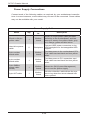
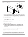
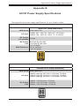
Power Supply
SC747 chassis model includes (93%+) Gold Level 1400W redundant (1+1) power
supplies rated at 1400 Watts or redundant 94% Platinum Level power supplies rated
at 1620 Watts. In the unlikely event your power supply fails, replacement is simple
and can be done without tools.
3-3 Where to get Replacement Components
Infrequently, you may need replacement parts for your system. To ensure the highest level of professional service and technical support, we strongly recommend
purchasing exclusively from our Supermicro Authorized Distributors/System Integrators/Resellers. A list of Supermicro Authorized Distributors/System Integrators/
Reseller can be found at: http://www.supermicro.com. Click the Where to Buy link.
3-2
Chapter 4 System Interface
Chapter 4
System Interface
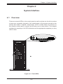
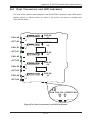
4-1Overview
There are several LEDs on the control panel as well as others on the drive carriers
to keep you constantly informed of the overall status of the system as well as the
activity and health of specific components. SC747 models have two buttons on
the chassis control panel, a power on/off button and a reset button. This chapter
explains the meanings of all LED indicators and the appropriate response you may
need to take.
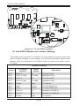
Figure 4-1: Front LEDs
4-1
SC747 Chassis Manual
4-2 Control Panel Buttons
There are two push-buttons located on the front of the chassis, a power on/off
button and a reset button.
•Power: The main power switch is used to apply or remove power from the power
supply to the server system. Turning off the power with this button removes the
main power but keeps standby power supplied to the system. Therefore, you
must unplug system before servicing.
•Reset: The reset button is used to reboot the system.
4-3 Control Panel LEDs
The control panel located on the front of the SC747chassis has five LEDs. These
LEDs provide you with critical information related to different parts of the system.
This section explains what each LED indicates when illuminated and any corrective
action you may need to take.
•HDD: Indicates SAS/SATA drive, and/or DVD-ROM drive activity when flashing.
•NIC1: Indicates network activity on GLAN1 when flashing.
4-2
Chapter 4 System Interface
•NIC2: Indicates network activity on GLAN2 when flashing.
•Overheat/Fan Fail: When this LED flashes it indicates a fan failure. When
continuously on (not flashing) it indicates an overheat condition, which may be
caused by cables obstructing the airflow in the system or the ambient room
temperature being too warm. Check the routing of the cables and make sure
all fans are present and operating normally. You should also check to make
sure that the chassis covers are installed. Finally, verify that the heatsinks are
installed properly. This LED will remain flashing or on as long as the overheat
condition exists.
!
•Power Fail: Indicates a power failure to the system's power supply units.
4-3
SC747 Chassis Manual
4-4 Drive Carrier LEDs
Your chassis uses SAS/SATA drives.
SAS/SATA Drives
Each SAS/SATA drive carrier has two LEDs.
•Green: Each Serial ATA drive carrier has a green LED. When illuminated, this
green LED (on the front of the SATA drive carrier) indicates drive activity. A connection to the SATA backplane enables this LED to blink on and off when that
particular drive is being accessed.
•Red: The red LED indicates a SAS/SATA drive failure. If one of the SAS/SATA
drives fail, you should be notified by your system management software.
4-4
Chapter 5 Chassis Setup and Maintenance
Chapter 5
Chassis Setup and Maintenance
5-1Overview
This chapter covers the steps required to install components and perform maintenance on the chassis. The only tool you will need to install components and perform
maintenance is a Phillips screwdriver. Print this page to use as a reference while
setting up your chassis.
5-2 Installation and Maintenance
Installation Procedures:
Chassis Covers
Removing the Main Cover
Opening the Front Cover
Configuring the Storage Module
Installing Hard Drives
Installing the Motherboard
IO Shield Installation
Permanent and Optional Standoffs
Installing the Heatsink
Power Supply Connections
Configuring the Expansion Slots
Installing Double-Width Graphics Cards
General Maintenance:
General Maintenance: Systems Fans
General Maintenance: Power Supply
Warning: Except for short periods of time, do NOT operate the server without the
cover in place. The chassis cover must be in place to allow proper airflow and
prevent overheating.
Review the warnings and precautions listed in the manual before setting up or
servicing this chassis. These include information in Chapter 2: System Safety and
the warning/precautions listed in the setup instructions.
5-1
SC747 Chassis Manual
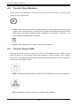
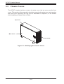
5-3 Chassis Covers
The SC747 chassis has three covers, the main cover, the top cover and the front
cover. This section of the manual is describes removing the main cover, and opening
the front cover. Removing the top cover is described in Chapter 6, in the section
titled Installing a Chassis onto a Rack.
Top Cover
Main Cover
Front Cover
Figure 5-1: Identifying the Chassis Covers
5-2
Chapter 5 Chassis Setup and Maintenance
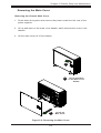
Removing the Main Cover
Removing the Chassis Main Cover
1. Power down the system and remove the power cords from the rear of the
power supplies.
2. Lift up and back on the main cover handle, which secures the cover to the
chassis.
3. Lift the main cover off of the chassis.
1
1
12
Lift Up and Back
on the Main Cover
Handle
Lift off the
Main Cover
Figure 5-2: Removing the Main Cover
5-3
SC747 Chassis Manual
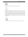
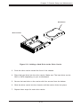
Front Cover Lock
Figure 5-3: Opening the Front Cover
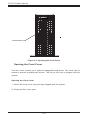
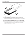
Opening the Front Cover
The front cover houses up to eight hot-swappable hard drives. The cover can be
locked to prevent unauthorized access. The key to this lock is shipped with the
system.
Opening the Front Cover
1. Unlock the front cover using the key shipped with the system.
2. Gently pull the cover open.
5-4
Chapter 5 Chassis Setup and Maintenance
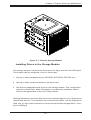
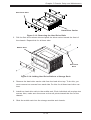
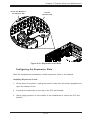
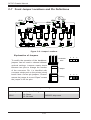
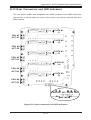
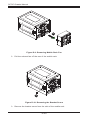
5-4 Configuring the the Storage Module
Storage Module
Figure 5-4: Chassis in Tower Mode
Storage Module
Figure 5-5: Chassis in Rack Mount Mode
Tower or Rack Configuration
The SC747 chassis is shipped in tower mode and can be immediately used as
desktop server. If the chassis is to be used in a rack, the storage module must be
rotated 90 degrees and the storage moudule cover must be replaced with a horizontal module cover, part number MCP-210-74703-0B. This can be done before,
during, or after setup. It is not necessary to replace the storage module cover when
the chassis is in the tower configuration.
5-5
SC747 Chassis Manual
Storage Module
Release Lever
Storage Module
Figure 5-6: Remove the Storage Module
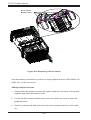
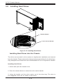
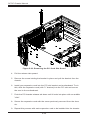
Rotating the Storage Module for Rack Mounting
1. Power down the system, remove the power cords from the rear of the power
supplies and open the chassis cover.
2. Locate the storage module and disconnect any cables from the storage module to any component in the chassis.
3. Push the storage module release lever. This lever unlocks the storage module.
4. Grasp the external edges of the storage module and pull the unit from the
chassis.
5. Turn the storage module 90 degrees as illustrated.
6. Reinsert the module into the chassis and reconnect the cables.
7. Reconnect the power cords and power up the system.
5-6
Chapter 5 Chassis Setup and Maintenance
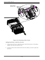
Figure 5-7: Chassis Storage Module
Installing Drives in the Storage Module
The storage module includes three full-sized drive bays and the front LED panel.
This module can be configured in one of three ways:
1. Add up to three peripheral drives (CD-ROM, DVD-ROM, DVD-RW etc.).
2. Add up to three extra hard drives to the drive trays.
3. Add five hot-swappable hard drives to the storage module. This configuration
requires a mobile rack. More information on mobile rack installation can be
found in the appendices at the end of this manual.
Warning! Enterprise level hard disk drives are recommended for use in Supermicro
chassis and servers. For information on recommended HDDs, visit the Supermicro
Web site at http://www.supermicro.com/products/nfo/files/storage/SAS-1-CompList-110909.pdf
5-7
SC747 Chassis Manual
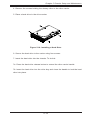
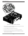
Drive Carrier
Release Tabs
Figure 5-8: Removing a Drive Carrier
Use the following instructions to add up to three peripheral drives (DVD-ROM, CDROM, etc.) to the drive trays:
Adding Peripheral Drives
1. Power down the system, remove the power cords from the back of the power
supplies and open the chassis cover.
2. Locate the drive carrier release tab for the slot where you want to place the
peripheral drive.
3. Press the release tab and push the drive carrier toward the front of the chassis.
5-8
Chapter 5 Chassis Setup and Maintenance
Hard Drive Carrier
Hard Drive Rails
Figure 5-9: Adding Hard Drive Rails to the DVD-ROM Drive
4. Remove the drive carrier rails from the drive carrier. To do this, you must remove
two screws from each side.
5. Attach the rails to a DVD-ROM, DVD-RW or other peripheral. The rails should fit
any standard sized 5.25" peripherals.
6. Slide the peripheral drive into the chassis until the carrier clicks into place.
7. Repeat these steps for each periperal drive.
5-9
SC747 Chassis Manual
Drive Carrier
Release Tabs
Figure 5-10: Removing a Drive Carrier
Adding Hard Drives to the Drive Carriers
1. Power down the server, unplug the power cords from the rear of the power
supplies and open the chassis cover.
2. Locate the drive carrier release tab for the slot where you want to place the
hard drive.
5-10
Chapter 5 Chassis Setup and Maintenance
Hard Drive
Drive Carrier
Figure 5-11: Adding a Hard Drive to the Drive Carrier
3. Push the drive carrier toward the front of the chassis.
4. Place the hard drive into the drive carrier. Make sure The hard drive can be
SAS or SATA depending on your motherboard.
5. Secure the hard drive to the carrier with four screws from the bottom.
6. Slide the drive carrier into the chassis until the carrier clicks into place.
7. Repeat these steps for each drive carrier.
5-11
SC747 Chassis Manual
Drive Carrier
Release Tabs
Figure 5-12: Removing a Drive Carrier
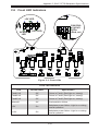
Adding Five Hard Drives Using a Supermicro Mobile Rack
The SC747 chassis supports a CSE-M35T-1/CSE-M35TQ mobile rack to install
extra hot-swappable hard drives. The mobile rack goes into the storage module
which goes into the chassis.
For more information on mobile rack installation and use, visit the Supermicro Web
site at www.supermicro.com.
Adding Hard Drives to a Supermicro Mobile Rack
1. Power down the system, disconnect the power cords from the rear of the
power supplies, and open the chassis cover.
2. Locate the drive release tabs.
5-12
Chapter 5 Chassis Setup and Maintenance
Hard Drive Rails
Hard Drive Carrier
Figure 5-13: Removing the Hard Drive Rails
3. Pull the first drive release tab and push the drive carrier toward the front of
the chassis. Repeat this for all three tabs.
Mobile Rack
Hard Drive
Rails
Figure 5-14: Adding Hard Drive Rails to a Storage Rack
4. Remove the hard drive carrier rails from the hard drive tray. To do this, you
must remove two screws from each side. Do this for all three hard drive carriers.
5. Install two hard drive rails to the mobile rack. Each individual rail requires two
screws. Also, make sure the arrow on the rail points toward the front of the
chassis.
6. Slide the mobile rack into the storage module and chassis.
5-13
SC747 Chassis Manual
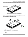
5-5 Installing Hard Drives
C
Release Button
Drive Carrier Handle
Figure 5-15: Installing Hard Drives
Installing Hard Drives into the Chassis
The drives are mounted in drive carriers to simplify their installation and removal
from the chassis. These carriers also help promote proper airflow for the drive bays.
Only enterprise level hard drives are recommended for use in Supermicro chassis.
Installing Hard Drives
1. Unlock and open the chassis cover.
2. Press the release button to extend the drive carrier handle.
3. Using the handle, pull the drive carrier out of the drive bay. The drive is
hot-swappable; there are no cables to disconnect.
5-14
Chapter 5 Chassis Setup and Maintenance
4. Remove the screws holding the dummy drive to the drive carrier.
5. Place a hard drive in the drive carrier.
Figure 5-16: Installing a Hard Drive
6. Secure the hard drive to the carrier using four screws.
7. Insert the hard drive into the chassis. To do this:
7a. Press the hard drive release button to extend the drive carrier handle.
7b. Insert the hard drive into the drive bay and close the handle to lock the hard
drive into place.
5-15
SC747 Chassis Manual
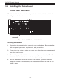
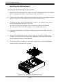
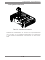
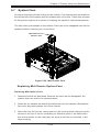
5-6 Installing the Motherboard
I/O Slot Shield Installation
The I/O shield holds the motherboard ports in place. In