1
SUPER
SuperWorkstation
7047GR-TPRF
USER’S MANUAL
Revision 1.0
®
The information in this User’s Manual has been carefully reviewed and is believed to be accurate.
The vendor assumes no responsibility for any inaccuracies that may be contained in this document,
makes no commitment to update or to keep current the information in this manual, or to notify any
person or organization of the updates. Please Note: For the most up-to-date version of this
manual, please see our web site at www.supermicro.com.
Super Micro Computer, Inc. ("Supermicro") reserves the right to make changes to the product
described in this manual at any time and without notice. This product, including software and
documentation, is the property of Supermicro and/or its licensors, and is supplied only under a
license. Any use or reproduction of this product is not allowed, except as expressly permitted by
the terms of said license.
IN NO EVENT WILL SUPERMICRO BE LIABLE FOR DIRECT, INDIRECT, SPECIAL, INCIDENTAL,
SPECULATIVE OR CONSEQUENTIAL DAMAGES ARISING FROM THE USE OR INABILITY TO
USE THIS PRODUCT OR DOCUMENTATION, EVEN IF ADVISED OF THE POSSIBILITY OF
SUCH DAMAGES. IN PARTICULAR, SUPERMICRO SHALL NOT HAVE LIABILITY FOR ANY
HARDWARE, SOFTWARE, OR DATA STORED OR USED WITH THE PRODUCT, INCLUDING THE
COSTS OF REPAIRING, REPLACING, INTEGRATING, INSTALLING OR RECOVERING SUCH
HARDWARE, SOFTWARE, OR DATA.
Any disputes arising between manufacturer and customer shall be governed by the laws of Santa
Clara County in the State of California, USA. The State of California, County of Santa Clara shall
be the exclusive venue for the resolution of any such disputes. Super Micro's total liability for all
claims will not exceed the price paid for the hardware product.
FCC Statement: This equipment has been tested and found to comply with the limits for a Class
A digital device pursuant to Part 15 of the FCC Rules. These limits are designed to provide
reasonable protection against harmful interference when the equipment is operated in a commercial
environment. This equipment generates, uses, and can radiate radio frequency energy and, if not
installed and used in accordance with the manufacturer’s instruction manual, may cause harmful
interference with radio communications. Operation of this equipment in a residential area is likely
to cause harmful interference, in which case you will be required to correct the interference at your
own expense.
California Best Management Practices Regulations for Perchlorate Materials: This Perchlorate
warning applies only to products containing CR (Manganese Dioxide) Lithium coin cells. “Perchlorate
Material-special handling may apply. See www.dtsc.ca.gov/hazardouswaste/perchlorate”
WARNING: Handling of lead solder materials used in this
product may expose you to lead, a chemical known to
the State of California to cause birth defects and other
reproductive harm.
Manual Revision 1.0
Release Date: July 16, 2012
Unless you request and receive written permission from Super Micro Computer, Inc., you may not
copy any part of this document.
Information in this document is subject to change without notice. Other products and companies
referred to herein are trademarks or registered trademarks of their respective companies or mark
holders.
Copyright © 2012 by Super Micro Computer, Inc.
All rights reserved.
Printed in the United States of America
Preface
Preface
About This Manual
This manual is written for professional system integrators and PC technicians.
It provides information for the installation and use of the SuperWorkstation
7047GR-TPRF. Installation and maintenance should be performed by experienced
technicians only.
The SuperWorkstation 7047GR-TPRF is based on the SC747TQ-R1620B 4U/Tower
rackmount chassis and the Super X9DRG-QF serverboard. Please refer to our web
site for an up-to-date list of supported operating systems, processors and memory.
Manual Organization
Chapter 1: Introduction
The first chapter provides a checklist of the main components included with the
workstation system and describes the main features of the Super X9DRG-QF
serverboard and the SC747TQ-R1620B chassis.
Chapter 2: Workstation Installation
This chapter describes the steps necessary to install the system into a rack and
check out the workstation configuration prior to powering up the system. If your
workstation was ordered without the processor and memory components, this
chapter will refer you to the appropriate sections of the manual for their installation.
Chapter 3: System Interface
Refer to this chapter for details on the system interface, which includes the functions
and information provided by the control panel on the chassis as well as other LEDs
located throughout the system.
Chapter 4: System Safety
You should thoroughly familiarize yourself with this chapter for a general overview
of safety precautions that should be followed when installing and servicing the
system.
Chapter 5: Advanced Serverboard Setup
Chapter 5 provides detailed information on the X9DRG-QF serverboard, including
the locations and functions of connectors, headers and jumpers. Refer to
iii
SUPERWORKSTATION 7047GR-TPRF User's Manual
this chapter when adding or removing processors or main memory and when
reconfiguring the serverboard.
Chapter 6: Advanced Chassis Setup
Refer to Chapter 6 for detailed information on the SC747TQ-R1620B 4U/Tower
rackmount chassis. You should follow the procedures given in this chapter when
installing, removing or reconfiguring Serial ATA or peripheral drives and when
replacing system power supply units and cooling fans.
Chapter 7: BIOS
The BIOS chapter includes an introduction to BIOS and provides detailed information
on running the CMOS Setup Utility.
Appendix A: BIOS Beep Codes
Appendix B: System Specifications
iv
Preface
Notes
v
SUPERWORKSTATION 7047GR-TPRF User's Manual
Table of Contents
Chapter 1 Introduction
1-1Overview.......................................................................................................... 1-1
1-2
Serverboard Features...................................................................................... 1-2
Processors....................................................................................................... 1-2
Memory............................................................................................................ 1-2
Serial ATA ........................................................................................................ 1-2
PCI Expansion Slots........................................................................................ 1-2
Rear I/O Ports.................................................................................................. 1-2
IPMI.................................................................................................................. 1-2
1-3
Chassis Features............................................................................................. 1-3
System Power.................................................................................................. 1-3
Mounting Rails (optional)................................................................................. 1-3
Hard Drive/Drive Bays..................................................................................... 1-3
Control Panel................................................................................................... 1-3
Cooling System................................................................................................ 1-3
1-4
GPU Subsystem............................................................................................... 1-4
1-5
Contacting Supermicro..................................................................................... 1-6
Chapter 2 Workstation Installation
2-1Overview.......................................................................................................... 2-1
2-2
Unpacking the System..................................................................................... 2-1
2-3
Preparing for Setup.......................................................................................... 2-2
Choosing a Setup Location.............................................................................. 2-2
Rack Precautions............................................................................................. 2-2
Workstation Precautions.................................................................................. 2-2
Rack Mounting Considerations........................................................................ 2-3
Ambient Operating Temperature................................................................. 2-3
Reduced Airflow.......................................................................................... 2-3
Mechanical Loading.................................................................................... 2-3
Circuit Overloading...................................................................................... 2-3
Reliable Ground.......................................................................................... 2-4
2-4
Installing the Chassis onto a Rack.................................................................. 2-4
Removing the Chassis Cover and Feet........................................................... 2-4
Identifying the Sections of the Rack Rails....................................................... 2-6
Installing the Chassis Handles and Inner Rails............................................... 2-6
Installing the Outer Rails to the Rack.............................................................. 2-7
Installing the Chassis into a Rack................................................................... 2-8
2-5
Tower Mounting Instructions............................................................................ 2-9
vi
Table of Contents
Installing the Chassis Cover............................................................................ 2-9
Installing Feet on the Chassis....................................................................... 2-10
Chapter 3 System Interface
3-1Overview.......................................................................................................... 3-1
3-2
Control Panel Buttons...................................................................................... 3-2
Power............................................................................................................... 3-2
Reset................................................................................................................ 3-2
3-3
Control Panel LEDs......................................................................................... 3-2
HDD.................................................................................................................. 3-2
NIC1................................................................................................................. 3-3
NIC2................................................................................................................. 3-3
Overheat/Fan Fail............................................................................................ 3-3
Power Fail........................................................................................................ 3-3
3-4
Drive Carrier LEDs........................................................................................... 3-4
Chapter 4 System Safety
4-1
Electrical Safety Precautions........................................................................... 4-1
4-2
General Safety Precautions............................................................................. 4-2
4-3
ESD Precautions.............................................................................................. 4-3
4-4
Operating Precautions..................................................................................... 4-4
Chapter 5 Advanced Serverboard Setup
5-1
Handling the Serverboard................................................................................ 5-1
Precautions...................................................................................................... 5-1
Unpacking........................................................................................................ 5-2
5-2
Connecting Cables........................................................................................... 5-2
Connecting Data Cables.................................................................................. 5-2
Connecting Power Cables............................................................................... 5-2
Connecting the Control Panel.......................................................................... 5-2
5-3
I/O Ports........................................................................................................... 5-3
5-4
Installing the Processor and Heatsink............................................................. 5-4
Installing an LGA2011 Processor..................................................................... 5-4
Installation and Removal of the Heatsink........................................................ 5-7
5-6
Installing Memory............................................................................................. 5-8
Memory Support for the X9DRG-QF Serverboard...................................... 5-9
5-6
Adding PCI Add-On Cards............................................................................. 5-12
5-7
Serverboard Details....................................................................................... 5-13
X9DRG-QF Quick Reference......................................................................... 5-13
5-8
Connector Definitions .................................................................................... 5-15
5-9
Jumper Settings............................................................................................. 5-22
5-10 Onboard Indicators......................................................................................... 5-24
vii
SUPERWORKSTATION 7047GR-TPRF User's Manual
5-11 SATA Ports..................................................................................................... 5-25
5-12 Installing Software.......................................................................................... 5-26
Supero Doctor III............................................................................................ 5-27
Chapter 6 Advanced Chassis Setup
6-1
Static-Sensitive Devices................................................................................... 6-2
Precautions...................................................................................................... 6-2
6-2
Control Panel................................................................................................... 6-2
6-3
System Cooling................................................................................................ 6-3
System Fan Failure.......................................................................................... 6-3
Replacing System Fans................................................................................... 6-3
6-4
Power Supply................................................................................................... 6-6
Power Supply Failure....................................................................................... 6-6
Replacing the Power Supply............................................................................ 6-6
Power Supply Connections.............................................................................. 6-7
6-5
Configuring the Storage Module ..................................................................... 6-8
Tower or Rack Configuration........................................................................... 6-8
Rotating the Storage Module........................................................................... 6-9
Installing Drives in the Storage Module......................................................... 6-10
Removing a Drive Carrier...............................................................................6-11
Adding Peripheral Drives............................................................................... 6-13
6-6
Installing Hard Drives in the Chassis............................................................. 6-14
Chapter 7 BIOS
7-1 Introduction....................................................................................................... 7-1
Starting BIOS Setup Utility............................................................................... 7-1
How To Change the Configuration Data.......................................................... 7-2
Starting the Setup Utility.................................................................................. 7-2
7-2 Main Setup....................................................................................................... 7-2
7-3 Advanced Setup Configurations...................................................................... 7-4
7-4 Event Logs..................................................................................................... 7-25
7-5 IPMI................................................................................................................ 7-27
7-6 Boot................................................................................................................ 7-29
7-7 Security.......................................................................................................... 7-30
7-8 Save & Exit.................................................................................................... 7-31
Appendix A BIOS Error Beep Codes
Appendix B System Specifications
viii
Chapter 1: Introduction
Chapter 1
Introduction
1-1Overview
The SuperWorkstation 7047GR-TPRF is comprised of two main subsystems: the
SC747TQ-R1620B 4U/Tower chassis and the X9DRG-QF dual Intel Xeon processor
serverboard. Please refer to our web site for information on operating systems that
have been certified for use with the system (www.supermicro.com).
In addition to the serverboard and chassis, various hardware components have
been included with the workstation, as listed below:
•Two 80-mm exhaust fans (FAN-0082L4)
•Two 92 x 38 mm front fans (FAN-0114L4)
•Two 80-mm rear fans (FAN-0116L4)
•Two 92 x 38 mm GPU fans (FAN-0138L4)
•Two 4U active CPU heatsinks (SNK-P0050AP4)
•SATA accessories:
One HD backplane (BPN-SAS-747TQ)
Eight 3.5" hard disk drive trays (MCP-220-00094-0B)
Three 5.25" drive trays (MCP-220-00073-0B)
•One SuperWorkstation 7047GR-TPRF User's Manual
•One Supermicro CD containing drivers and utilities
Optional
•One 4U 17.2" width rack rail set (MCP-290-00059-0N)
1-1
SUPERWORKSTATION 7047GR-TPRF User's Manual
1-2 Serverboard Features
At the heart of the SuperWorkstation 7047GR-TPRF lies the X9DRG-QF, a dual
processor serverboard based on the Intel C602 chipset. Below are the main features
of the X9DRG-QF. (See Figure 1-1 for a block diagram of the chipset).
Processors
The X9DRG-QF supports two Intel® E5-2600 Series processors in LGA 2011 sockets
(Socket R). Please refer to the serverboard description pages on our web site for a
complete listing of supported processors (www.supermicro.com).
Memory
The X9DRG-QF has sixteen DIMM slots that can support up to 512 GB of DDR31600/1333/1066/800 RDIMM, LRDIMM or UDIMM ECC/non-ECC memory. Modules
of the same size and speed are recommended. See Chapter 5 for details.
Serial ATA
A SATA controller is integrated into the chipset to provide a ten-port SATA subsystem,
which is RAID 0, 1, 5 and 10 supported. the I-SATA 0-5 ports are SATA 3.0 ports and
the S-SATA1-3 ports are SATA 2.0 ports. The SATA drives are hot-swappable units.
Note: The operating system you use must have RAID support to enable the hotswap capability and RAID function of the Serial ATA drives.
PCI Expansion Slots
The X9DRG-QF has four PCI-E 3.0 x16, two PCI-E 3.0 x8 (in x16) and one PCI-E
2.0 x4 (in x8) slots for a total of seven PCI expansion slots.
Rear I/O Ports
The color-coded I/O ports include one COM port, a VGA (monitor) port, four USB
2.0 ports, a dedicated IPMI LAN port and two Gb Ethernet LAN ports.
IPMI
IPMI (Intelligent Platform Management Interface) is a hardware-level interface
specification that provides remote access, monitoring and administration for
Supermicro workstation platforms. IPMI allows administrators to view a workstation’s
hardware status remotely, receive an alarm automatically if a failure occurs, and
power cycle a system that is non-responsive.
1-2
Chapter 1: Introduction
1-3 Chassis Features
The following is a general outline of the main features of the SC747TQ-R1620B
chassis.
System Power
The SC747TQ-R1620B chassis includes a 1620W high-efficiency, redundant (1+1)
power supply consisting of two power supply modules. In the unlikely event a power
supply module fails, replacement is simple and can be done without tools. The AC
power cord should be removed from the system before servicing or replacing a
power supply module. See Chapter 6 for details.
Mounting Rails (optional)
The SC747 can be placed in a rack for secure storage and use. To setup your rack,
follow the step-by-step instructions included in this manual in Chapter 2.
Hard Drive/Drive Bays
The SC747 chassis features eight drive bays for SATA drives. These drives are hot
-swappable. Once set up correctly, these drives can be removed without powering
down the workstation.
The SC747 chassis also provides three 5.25” peripheral drive bays for floppy drives,
DVD-ROM/CD-ROM drives, or additional hard drives.
Control Panel
The control panel on the workstation provides you with system monitoring and
control. LEDs indicate system power, HDD activity, network activity, system
overheat, UID and power supply failure. A main power button and a system reset
button are also included.
Cooling System
The SC747 chassis accepts four system fans and two rear exhaust fans. System
fans are powered from the serverboard. These fans are 4U high and are powered
by 4-pin connectors.
1-3
SUPERWORKSTATION 7047GR-TPRF User's Manual
1-4 GPU Subsystem
The 7047GR-TPRF server is a massively parallel-processing, quad-GPU servers,
with support for up to four NVIDIA® Fermi™ GPUs, placing this system at the
forefront of today's GPU computing solutions.
Please refer to the NVIDIA web site (www.nvidia.com) for details on Fermi GPUs.
Notes
The GPUs process complex image calculations and then route the data out through
the VGA port on the serverboard.
The 7047GR-TPRF can support four standard size (double-width) GPUs (currently
the M2075 or M2090 models at this time). Please check our web site for updates
on new GPUs as they are qualified for use in the 7047GR-TPRF
The GPUs can be bundled with the system as follows:
System Name
GPU Configuration
7047GR-TPRF-FM409
4x NVIDIA Tesla M2090 GPUs
7047GR-TPRF-FM475
4x NVIDIA Tesla M2075 passive GPUs
1-4
Chapter 1: Introduction
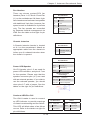
Figure 1-1. Intel C602 Chipset:
System Block Diagram
Note: This is a general block diagram. Please see Chapter 5 for details.
x4
JPEIC11 PCIE3.0 x8
x8
JPEIC9 PCIE3.0 x8
x16
JPEIC8 PCIE3.0 x16
x16
DDR3 DIMM
#1
#2
Sandybridge
PE3 PE2 PE1 DMI
A
x16
x16
BIOS
SPI Flash
DMI: LANE Reversal
x8
SPI
DMI
SATA Gen3 [0..3]
PET8
USB [10,11]
DDR3 RAM
x1
VGA
UM1
RENESAS
BMC
VGA CONN
0,1
USB [0..9]
PHY
RTL8211E
IPMI LAN
RJ45
1-5
2,3
port 4 port 5
HDR 2X5
JLAN2
RJ45
PET [1..7]
SSB
PATSBURG-A
HDR 2X5
JLAN1
RJ45
SATA [0..5]
PEG [0..3]
SAS2/SATA Gen3
6Gbps
I-SATA9
I-SATA8
I-SATA7
I-SATA6
UL1
Powerville Dual GbE
I350AM2
SATA Gen2
3Gbps
B
DDR3 DIMM
#1
#2
P0
CPU REAR
U6H1 Socket 00
SATA Gen3
6Gbps
JPEIC10 PCIE3.0 x16
P1
G
I-SATA0
I-SATA1
I-SATA2
I-SATA3
I-SATA4
I-SATA5
JPEIC2 PCIE3.0 x16
P1
#1
#2
REAR REAR TYPE A TYPE A 6,7 8,9
LPC
TPM Header
JPEIC4 PCIE3.0 x16
H
DDR3 DIMM
P0
#1
#2
DMI
DDR3 DIMM
C
PE1
CPU REAR
U7C1 Socket 01
Processor
Sandybridge
P00_P11
LANE Reversal
#1
#2
D
#1
#2
DDR3 DIMM
PE3 PE2
F
QPI
E
DDR3 DIMM
#1
#2
DDR3 DIMM
DDR3 DIMM
#1
#2
QPI
JPEIC6 PCIE3.0 x16
Super I/O
W83527
HW Monitor
NCT7904D
SUPERWORKSTATION 7047GR-TPRF User's Manual
1-5 Contacting Supermicro
Headquarters
Address:
Super Micro Computer, Inc.
980 Rock Ave.
San Jose, CA 95131 U.S.A.
Tel:
+1 (408) 503-8000
Fax:
+1 (408) 503-8008
Email:
[email protected] (General Information)
[email protected] (Technical Support)
Web Site:
www.supermicro.com
Europe
Address:
Super Micro Computer B.V.
Het Sterrenbeeld 28, 5215 ML
's-Hertogenbosch, The Netherlands
Tel:
+31 (0) 73-6400390
Fax:
+31 (0) 73-6416525
Email:
[email protected] (General Information)
[email protected] (Technical Support)
[email protected] (Customer Support)
Asia-Pacific
Address:
Super Micro Computer, Inc.
4F, No. 232-1, Liancheng Rd.
Chung-Ho Dist., New Taipei City 235
Taiwan
Tel:
+886-(2) 8226-3990
Fax:
+886-(2) 8226-3991
Web Site:
www.supermicro.com.tw
Technical Support:
Email:
[email protected]
Tel: 886-2-8228-1366, ext.132 or 139
1-6
Chapter 2: Workstation Installation
Chapter 2
Workstation Installation
2-1Overview
This chapter provides a quick setup checklist to get your SuperWorkstation 7047GRTPRF up and running. Following the steps in the order given should enable you
to have the system operational within a minimal amount of time. If your system is
not already fully integrated with a motherboard, processor, system memory etc.,
please turn to the chapter or section noted in each step for details on installing
specific components.
2-2 Unpacking the System
You should inspect the box the SuperWorkstation 7047GR-TPRF was shipped in
and note if it was damaged in any way. If the workstation itself shows damage, you
should file a damage claim with the carrier who delivered it.
Decide on a suitable location for setting up and operating the SuperWorkstation
7047GR-TPRF. It should be situated in a clean, dust-free area that is well ventilated.
Avoid areas where heat, electrical noise and electromagnetic fields are generated.
You will also need it placed near a grounded power outlet.
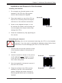
!
Warnings and Precautions!
!
•Review the electrical and general safety precautions in Chapter 4.
•Use a regulating uninterruptible power supply (UPS) to protect the workstation
from power surges, voltage spikes and to keep your system operating in case
of a power failure.
•Allow the power supply units and Serial ATA drives to cool before touching
them.
•To maintain proper cooling, always keep all chassis panels closed when not
being serviced.
2-1
SUPERWORKSTATION 7047GR-TPRF User's Manual
2-3 Preparing for Setup
The box your workstation was shipped in may include two sets of rail assemblies,
two rail mounting brackets and the mounting screws needed to install the system
into the rack (optional parts). Please read this section in its entirety before you begin
the installation procedure outlined in the sections that follow.
Choosing a Setup Location
•Leave enough clearance in front of the rack to enable you to open the front
door completely (~25 inches).
•Leave approximately 30 inches of clearance in the back of the rack to allow for
sufficient airflow and ease in servicing.
•This product is for installation only in a Restricted Access Location (dedicated
equipment rooms, service closets and the like).
!
Warnings and Precautions!
!
Rack Precautions
•Ensure that the leveling jacks on the bottom of the rack are fully extended to
the floor with the full weight of the rack resting on them.
•In single rack installation, stabilizers should be attached to the rack. In multiple
rack installations, the racks should be coupled together.
•Always make sure the rack is stable before extending a component from the
rack.
•You should extend only one component at a time - extending two or more simultaneously may cause the rack to become unstable.
•Rack-mounted equipment should not be used as a shelf or work space.
Workstation Precautions
•Review the electrical and general safety precautions in Chapter 4.
•Determine the placement of each component in the rack before you install the
rails.
2-2
Chapter 2: Workstation Installation
•Install the heaviest workstation components on the bottom of the rack first, and
then work up.
•Use a regulating uninterruptible power supply (UPS) to protect the workstation
from power surges, voltage spikes and to keep your system operating in case
of a power failure.
•Allow the hot plug SATA drives and power supply modules to cool before touching them.
•Always keep the rack's front door and all panels and components on the workstations closed when not servicing to maintain proper cooling.
Rack Mounting Considerations
Ambient Operating Temperature
If installed in a closed or multi-unit rack assembly, the ambient operating temperature of the rack environment may be greater than the ambient temperature of the
room. Therefore, consideration should be given to installing the equipment in an
environment compatible with the manufacturer’s maximum rated ambient temperature (Tmra).
Reduced Airflow
Equipment should be mounted into a rack so that the amount of airflow required
for safe operation is not compromised.
Mechanical Loading
Equipment should be mounted into a rack so that a hazardous condition does not
arise due to uneven mechanical loading.
Circuit Overloading
Consideration should be given to the connection of the equipment to the power
supply circuitry and the effect that any possible overloading of circuits might have
on overcurrent protection and power supply wiring. Appropriate consideration of
equipment nameplate ratings should be used when addressing this concern.
2-3
SUPERWORKSTATION 7047GR-TPRF User's Manual
Reliable Ground
A reliable ground must be maintained at all times. To ensure this, the rack itself
should be grounded. Particular attention should be given to power supply connections other than the direct connections to the branch circuit (i.e. the use of power
strips, etc.).
2-4 Installing the Chassis onto a Rack
This section provides information on installing the SC747 chassis into a rack unit
with the optional 4U 17.2" width rail set (MCP-290-00059-0B). There are a variety
of rack units on the market, which may mean the assembly procedure will differ
slightly. You should also refer to the installation instructions that came with the rack
unit you are using.
Notes: The outer rail is adjustable from 26" to 38.25". The MCP-290-00059-0N rail
kit is an optional accessory.
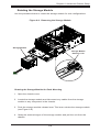
Removing the Chassis Cover and Feet
The SC747 chassis is shipped with the chassis cover and feet pre-installed. Both
the feet and cover must be removed for before installing the rails.
Removing the Chassis Top Cover
1. Locate the chassis cover lock (blue lever) at the rear of the chassis cover.
2. Slide the chassis cover lock to the right and push chassis cover forward.
3. Lift the chassis top cover off the chassis.
Removing the Chassis Feet
1. Place the chassis on its side with the chassis side cover facing upward.
2. Remove the screw holding the chassis foot in place.
3. The foot lock is a tab located in the center of the foot that prevents the foot
from sliding. Using a flat head screwdriver, gently lift the foot lock upward
and slide the foot toward the rear of the chassis.
4. Repeat steps 2 and 3 with each remaining foot.
2-4
Chapter 2: Workstation Installation
Figure 2-1. Removing the Feet and Chassis Top Cover
Chassis Cover
Chassis Feet
Chassis Cover Lock
2-5
SUPERWORKSTATION 7047GR-TPRF User's Manual
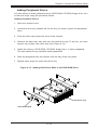
Identifying the Sections of the Rack Rails
The chassis package includes two rack rail assemblies in the rack mounting kit.
Each assembly consists of two sections: an inner fixed chassis rail that secures
directly to the workstation chassis and an outer fixed rack rail that secures directly
to the rack itself.
Figure 2-2. Identifying the Inner Rails and Chassis Handles
Inner Rails
Chassis Handle
Installing the Chassis Handles and Inner Rails
Installing the Inner Rails
1. Locate the chassis handles and handle screws.
2. Align the chassis handle with the front of the chassis and secure with the
three chassis handle screws.
3. Repeats steps 1 and 2 with the other handle.
4. Locate the inner rails and screws in the shipping package.
5. Align the inner rails against the chassis, as shown. Confirm that the rails are
flushed against the edge of the chassis.
6. Tighten the screws. Do not over-tighten.
7. Repeat steps 5 and 6 with the other inner rail.
2-6
Chapter 2: Workstation Installation
Figure 2-3. Installing the Inner Rack Rails
Installing the Outer Rails to the Rack
Installing the Outer Rails
1. Attach the rear bracket to the middle bracket.
2. Adjust both the brackets to the proper distance so that the rail fits snugly into
the rack.
3. Secure the rear of the outer rail with two M5 screws and the rear of the rack.
Note: The outer rail is adjustable from approximately 26" to 38.25".
4. Repeat steps 1-3 for the left outer rail.
Figure 2-4. Assembling the Outer Rails
Slide into the Inner Rail
Secure to the
Rear of the Rack
Attach to Middle Rail
2-7
SUPERWORKSTATION 7047GR-TPRF User's Manual
Figure 2-5. Installing the Rack Rails
Installing the Chassis into a Rack
Installing the Chassis
1. Confirm that chassis includes the inner rails and the outer rails.
2. Align the inner chassis rails with the front of the outer rack rails (C).
3. Slide the inner rails into the outer rails, keeping the pressure even on both
sides (you may have to depress the locking tabs when inserting). When
the chassis has been pushed completely into the rack, you should hear the
locking tabs "click" into the locked position.
2-8
Chapter 2: Workstation Installation
2-5 Tower Mounting Instructions
The SC747 chassis is shipped with the chassis cover and feet pre-installed. To use
the chassis as a desktop workstation, no other installation is required.
Use the instructions in this section if you have converted the chassis for rack use
and need to return the chassis to tower mounting.
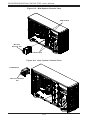
Figure 2-6. Adding Chassis Feet and Top Cover
Chassis Cover
Chassis Rackmount Ears
Chassis Feet
Installing the Chassis Cover
Installing the Cover
1. Remove the rack mount ears.
2. Align the cover post with the corresponding holes on the top of the chassis
and place the cover on top of the chassis. The cover should overhang
approximately one-half inch over the front of the chassis.
3. Slide the chassis cover toward the rear of the chassis to lock the cover into
place.
2-9
SUPERWORKSTATION 7047GR-TPRF User's Manual
Figure 2-7. Placing Chassis Feet
Chassis Foot
Receptacle
Chassis Foot
Chassis Screw
Installing Feet on the Chassis
Installing the Chassis Feet
1. Place the chassis foot in the foot receptacle and slide the foot toward the
front of the chassis. The foot should lock into place.
2. Secure the foot to the chassis using one screw enclosed in the packaging.
3. Repeat steps 1 and 2 for the remaining three chassis feet.
2-10
Chapter 3: System Interface
Chapter 3
System Interface
3-1Overview
There are several LEDs on the control panel as well as others on the drive carriers
to keep you constantly informed of the overall status of the system as well as the
activity and health of specific components. There are two buttons on the chassis
a control panel: a reset button and an on/off switch. This chapter explains the
meanings of all LED indicators and the appropriate response you may need to take.
Figure 3-1. Front LEDs
3-1
SUPERWORKSTATION 7047GR-TPRF User's Manual
3-2 Control Panel Buttons
There are two push-buttons located on the front of the chassis. These are power
on/off button and a reset button.
Power
The main power switch is used to apply or remove power from the power supply
to the workstation. Turning off system power with this button removes the main
power but keeps standby power supplied to the system. Therefore, you must unplug
system before servicing.
Reset
The reset button is used to reboot the system.
3-3 Control Panel LEDs
The control panel located on the front of the SC747 chassis has five LEDs. These
LEDs provide you with critical information related to different parts of the system.
This section explains what each LED indicates when illuminated and any corrective
action you may need to take.
HDD
Indicates IDE channel activity. SAS/SATA and/or DVD-ROM drive activity when
flashing.
3-2
Chapter 3: System Interface
NIC1
Indicates network activity on LAN1 when flashing.
NIC2
Indicates network activity on LAN2 when flashing.
Overheat/Fan Fail
When this LED flashes it indicates a fan failure. When continuously on (not flashing)
it indicates an overheat condition, which may be caused by cables obstructing the
airflow in the system or the ambient room temperature being too warm. Check the
routing of the cables and make sure all fans are present and operating normally.
You should also check to make sure that the chassis covers are installed. Finally,
verify that the heatsinks are installed properly. This LED will remain flashing or on
as long as the overheat condition exists.
!
Power Fail
Indicates a power failure to the system's power supply units.
3-3
SUPERWORKSTATION 7047GR-TPRF User's Manual
3-4 Drive Carrier LEDs
Each SATA drive carrier has two LEDs.
•Green: Each drive carrier has a green LED. When illuminated, this green LED
(on the front of the drive carrier) indicates drive activity. A connection to the
SATA backplane enables this LED to blink on and off when that particular drive
is being accessed.
•Red: The red LED indicates a SATA drive failure. If one of the SATA drives fail,
you should be notified by your system management software.
3-4
Chapter 4: System Safety
Chapter 4
System Safety
4-1 Electrical Safety Precautions
!
Note: power should always be disconnected before performing any service
on the system.
Basic electrical safety precautions shall be followed to protect yourself from harm
and the workstation from damage:
•Be aware of the locations of the power on/off switch on the chassis as well
as the room's emergency power-off switch, disconnection switch or electrical
outlet. If an electrical accident occurs, you can then quickly remove power from
the system.
•Do not work alone when working with high voltage components.
•Power should always be disconnected from the system when removing or in-
stalling main system components, such as the serverboard, memory modules
and floppy drive. When disconnecting power, you should first power down the
system with the operating system first and then unplug the power cords of all
the power supply units in the system.
•When working around exposed electrical circuits, another person who is familiar
with the power-off controls should be nearby to switch off the power if necessary.
•Use only one hand when working with powered-on electrical equipment. This
is to avoid making a complete circuit, which will cause electrical shock. Use
extreme caution when using metal tools, which can easily damage any electrical
components or circuit boards they come into contact with.
•Do not use mats designed to decrease static electrical discharge as protection
from electrical shock. Instead, use rubber mats that have been specifically
designed as electrical insulators.
•The power supply power cords must include a grounding plug and must be
plugged into grounded electrical outlets.
4-1
SUPERWORKSTATION 7047GR-TPRF User's Manual
•This product may be connected to an IT power system. In all cases, make sure
that the unit is also reliably connected to Earth (ground).
•Serverboard Battery: CAUTION - There is a danger of explosion if the onboard
battery is installed upside down, which will reverse its polarites (see Figure 4-1).
This battery must be replaced only with the same or an equivalent type recommended by the manufacturer (CR2032). Dispose of used batteries according to
the manufacturer's instructions.
•DVD-ROM Laser: CAUTION - this workstation may have come equipped with a
DVD-ROM drive. To prevent direct exposure to the laser beam and hazardous
radiation exposure, do not open the enclosure or use the unit in any unconventional way.
•Mainboard replaceable soldered-in fuses: Self-resetting PTC (Positive Tempera-
ture Coefficient) fuses on the mainboard must be replaced by trained service
technicians only. The new fuse must be the same or equivalent as the one
replaced. Contact technical support for details and support.
4-2 General Safety Precautions
!
Follow these rules to ensure general safety:
•Keep the area around the workstation clean and free of clutter.
•The workstation weighs approximately 72 lbs. (32.7 kg) when fully loaded. When
lifting the system, two people at either end should lift slowly with their feet spread
out to distribute the weight. Always keep your back straight and lift with your legs.
•Place the chassis top cover and any system components that have been re-
moved away from the system or on a table so that they won't accidentally be
stepped on.
•While working on the system, do not wear loose clothing such as neckties and
unbuttoned shirt sleeves, which can come into contact with electrical circuits or
be pulled into a cooling fan.
4-2
Chapter 4: System Safety
•Remove any jewelry or metal objects from your body, which are excellent metal
conductors that can create short circuits and harm you if they come into contact
with printed circuit boards or areas where power is present.
•After accessing the inside of the system, close the system back up and secure
it to the rack unit with the retention screws after ensuring that all connections
have been made.
4-3 ESD Precautions
!
Electrostatic Discharge (ESD) is generated by two objects with different electrical
charges coming into contact with each other. An electrical discharge is created to
neutralize this difference, which can damage electronic components and printed
circuit boards. The following measures are generally sufficient to neutralize this
difference before contact is made to protect your equipment from ESD:
•Use a grounded wrist strap designed to prevent static discharge.
•Keep all components and printed circuit boards (PCBs) in their antistatic bags
until ready for use.
•Touch a grounded metal object before removing the board from the antistatic
bag.
•Do not let components or PCBs come into contact with your clothing, which may
retain a charge even if you are wearing a wrist strap.
•Handle a board by its edges only; do not touch its components, peripheral chips,
memory modules or contacts.
•When handling chips or modules, avoid touching their pins.
•Put the serverboard and peripherals back into their antistatic bags when not
in use.
•For grounding purposes, make sure your computer chassis provides excellent
conductivity between the power supply, the case, the mounting fasteners and
the serverboard.
4-3
SUPERWORKSTATION 7047GR-TPRF User's Manual
4-4 Operating Precautions
!
Care must be taken to assure that the chassis cover is in place when the system
is operating to ensure proper cooling. Out of warranty damage to the system can
occur if this practice is not strictly followed.
Figure 4-1. Installing the Onboard Battery
LITHIUM BATTERY
LITHIUM BATTERY
OR
BATTERY HOLDER
BATTERY HOLDER
!
Please handle used batteries carefully. Do not damage the battery in any way; a
damaged battery may release hazardous materials into the environment. Do not
discard a used battery in the garbage or a public landfill. Please comply with the
regulations set up by your local hazardous waste management agency to dispose
of your used battery properly.
4-4
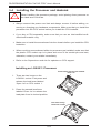
Chapter 5: Advanced Serverboard Setup
Chapter 5
Advanced Serverboard Setup
This chapter covers the steps required to install the X9DRG-QF serverboard into the
chassis, connect the data and power cables and install add-on cards. All serverboard
jumpers and connections are also described. A layout and quick reference chart
are included in this chapter for your reference. Remember to completely close the
chassis when you have finished working with the serverboard to better cool and
protect the system.
5-1 Handling the Serverboard
Electrostatic Discharge (ESD) can damage electronic com
ponents. To prevent
damage to any printed circuit boards (PCBs), it is important to handle them very
carefully (see previous chapter). To prevent the serverboard from bending, keep
one hand under the center of the board to support it when handling. The following
measures are generally sufficient to protect your equipment from electric static
discharge.
Precautions
•Use
a grounded wrist strap designed to prevent Electrostatic Discharge
(ESD).
•Touch a grounded metal object before removing any board from its antistatic
bag.
•Handle a board by its edges only; do not touch its components, peripheral chips,
memory modules or gold contacts.
•When handling chips or modules, avoid touching their pins.
•Put the serverboard, add-on cards and peripherals back into their antistatic
bags when not in use.
•For grounding purposes, make sure your computer chassis provides excellent
conductivity between the power supply, the case, the mounting fasteners and
the serverboard.
5-1
SUPERWORKSTATION 7047GR-TPRF User's Manual
Unpacking
The serverboard is shipped in antistatic packaging to avoid electrical static
discharge. When unpacking the board, make sure the person handling it is static
protected.
5-2 Connecting Cables
Several cables need to be connected from the chassis to the serverboard. These
include the data cables for the peripherals and control panel and the power cables.
Connecting Data Cables
The cables used to transfer data from the peripheral devices have been carefully
routed to prevent them from blocking the flow of cooling air that moves through
the system from front to back. If you need to disconnect any of these cables, you
should take care to keep them routed as they were originally after reconnecting
them (make sure the red wires connect to the pin 1 locations). The following data
cables (with their locations noted) should be connected. (See the serverboard layout
for connector locations.)
•SATA drive data cables (I-SATA0 ~ SATA7 )
•Control Panel cable (JF1)
Important! Make sure the the cables do not come into contact with the fans.
Connecting Power Cables
The X9DRG-QF has a 24-pin proprietary power supply connector (JPW1) for
connection to the ATX power supply. In addition, there are two 8-pin secondary
power connectors (JPW2, JPW3) that also must be connected to your power supply.
See Section 5-8 for power connector pin definitions.
Connecting the Control Panel
JF1 contains header pins for various front control panel connectors. See Figure 5-1
for the pin locations of the various front control panel buttons and LED indicators.
All JF1 wires have been bundled into a single ribbon cable to simplify this
connection. Make sure the red wire plugs into pin 1 as marked on the board. The
other end connects to the Control Panel PCB board, located just behind the system
status LEDs on the chassis. See below for details and pin descriptions.
5-2
Chapter 5: Advanced Serverboard Setup
Figure 5-1. Control Panel Header Pins
20
19
Ground
NMI
X
X
3.3 V
FP PWRLED
ID_UID_SW/3/3V Stby
HDD LED
NIC1 Link LED
NIC1 Activity LED
NIC2 Link LED
NIC2 Activity LED
Blue+ (OH/Fan Fail/
PWR FaiL/UID LED)
Red+ (Blue LED Cathode)
Power Fail LED
3.3V
Ground
Ground
2
Reset
Reset Button
PWR
Power Button
1
5-3 I/O Ports
The I/O ports are color coded in conformance with the PC 99 specification. See
Figure 5-2 below for the colors and locations of the various I/O ports.
Figure 5-2. I/O Ports
14
16
1
13
12
15
17
18
Rear I/O Ports
1. COM1 Port
2. USB0 Port
3. USB1 Port
4. Dedicated IPMI LAN Port
5. USB2 Port
6. USB3 Port
7. LAN1 Port
8. LAN2 Port
9. VGA Port
10. UID Switch
5-3
19
1
10
SUPERWORKSTATION 7047GR-TPRF User's Manual
5-4 Installing the Processor and Heatsink
When handling the processor package, avoid placing direct pressure on
!
the label area of the fan.
Notes:
•Always connect the power cord last and always remove it before adding, re-
moving or changing any hardware components. Make sure that you install the
processor into the CPU socket before you install the CPU heatsink.
•If you buy a CPU separately, make sure that you use an Intel-certified multidirectional heatsink only.
•Make sure to install the serverboard into the chassis before you install the CPU
heatsinks.
•When receiving a serverboard without a processor pre-installed, make sure that
the plastic CPU socket cap is in place and none of the socket pins are bent;
otherwise, contact your retailer immediately.
•Refer to the Supermicro web site for updates on CPU support.
Installing an LGA2011 Processor
Press down on the lever labeled
'Close 1st'
1. There are two levers on the
LGA2011 socket. First press and
release the load lever labeled
'Open 1st' on CPU socket 1.
WA
R
NI
OP
2. Press the second load lever
labeled 'Close 1st' to release the
load plate from its locked position.
EN
NG
!
1st
Pull lever away
from the socket
WA
R
NI
OP
EN
5-4
1st
NG
!
Chapter 5: Advanced Serverboard Setup
3. With the lever labeled 'Close 1st'
fully retracted, gently push down
on the 'Open 1st' lever to open the
load plate. Lift the load plate to
open it completely.
WA
R
NI
OP
EN
NG
!
1st
Gently push
down to pop
the load plate
open.
4. Using your thumb and the index
finger, remove the 'WARNING'
plastic cap from the socket.
5. Use your thumb and index finger
to hold the CPU by its edges. Align
the CPU keys, which are semicircle cutouts, against the socket
keys.
WA
R
NI
NG
!
6. Once they are aligned, carefully
lower the CPU straight down into
the socket. (Do not drop the CPU
on the socket. Do not move the
CPU horizontally or vertically and
do not rub the CPU against any
pins of the socket, which may
damage the CPU or the socket.)
Socket Keys
CPU Keys
5-5
SUPERWORKSTATION 7047GR-TPRF User's Manual
!
Warning: You can only install the CPU to the socket in one direction. Make
sure that the CPU is properly inserted into the socket before closing the
load plate. If it doesn't close properly, do not force it as it may damage
your CPU. Instead, open the load plate again and double-check that the
CPU is aligned properly.
7. With the CPU in the socket,
inspect the four corners of the
CPU to make sure that they are
flush with the socket.
Gently close
the load plate.
8. Close the load plate. Lock the
lever labeled 'Close 1st', then lock
the lever labeled 'Open 1st'. Use
your thumb to gently push the
load levers down until the lever
locks.
9. Repeat steps to install a CPU to
socket 2.
Push down and lock the
level labeled 'Close 1st'.
OP
EN
1st
Lever Lock
OP
EN
1st
Push down
and lock the
lever labeled
'Open 1st'.
5-6
Chapter 5: Advanced Serverboard Setup
Installation and Removal of the Heatsink
Installing the Heatsink
1. Do not apply any thermal grease to the
heatsink or the CPU die; the required
amount has already been applied.
2. Place the heatsink on top of the CPU so
that the four mounting holes are aligned
with those on the retention mechanism.
Screw #1
3. Screw in two diagonal screws (i.e. the
#1 and the #2 screws) until just snug (do
not over-tighten the screws, which may
damage the CPU.)
Screw #2
4. Finish the installation by fully tightening all
four screws.
Uninstalling the Heatsink
!
Warning: We do not recommend removing the CPU or the heatsink.
However, if you do need to uninstall the heatsink, please follow these
instructions to avoid damaging the CPU or the CPU socket.
1. Unscrew and remove the heatsink screws
in the sequence shown in the picture on
the right.
2. Hold the heatsink as shown in the picture
on the right and gently wriggle to loosen
it from the CPU. (Do not use excessive
force when doing this!)
Screw #1
Screw #3
Screw #4
Screw #2
3. Once the heatsink is loosened, remove it
from the CPU socket.
4. Clean the surface of the CPU and the
heatsink to get rid of the old thermal
grease. Reapply the proper amount of
thermal grease before you re-install the
heatsink.
5-7
SUPERWORKSTATION 7047GR-TPRF User's Manual
5-6 Installing Memory
!
CAUTION! Exercise extreme care when installing or removing DIMM
modules to prevent any possible damage.
Installing Memory Modules
1. Insert the desired number of DIMMs into the memory slots, starting with
P1-DIMMA1. For best memory performance, please install memory modules
of the same type and same speed on the memory slots as indicated on the
tables below.
2. Insert each DIMM module vertically into its slot. Pay attention to the notch
along the bottom of the module to avoid installing incorrectly (see Figure 5-3).
3. Gently press down on the DIMM module until it snaps into place in the slot.
Repeat for all modules.
Figure 5-3. DIMM Installation
Notch
Notch
To Install: Insert module
vertically and press
down until it snaps into
place. Pay attention to
the alignment notch at
the bottom.
To Remove:
Use your thumbs to
gently push the release
tabs near both ends of
the module. This should
release it from the slot.
Front View
Note: Notch should align
with the receptive key
point on the slot.
Release Tab
Top View of DDR3 Slot
5-8
Release Tab
Chapter 5: Advanced Serverboard Setup
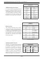
Memory Support for the X9DRG-QF Serverboard
The X9DRG-QF serverboard supports up to 512 GB of DDR3-1600/1333/1066/800
RDIMM, LRDIMM or UDIMM ECC/non-ECC memory in 16 DIMM slots. See the
following table for memory installation. For the latest memory updates, please refer
to our website a at http://www.supermicro.com/products/serverboard.
Processor & Memory Module Population Configuration
For memory to work properly, follow the tables below for memory population.
Processors and their Corresponding Memory Modules
CPU#
Corresponding DIMM Modules
CPU 1
P1DIMMA1
P1DIMMB1
P1DIMMC1
P1DIMMD1
P1DIMMA2
P1DIMMB2
P1DIMMC2
P1DIMMD2
CPU2
P2DIMME1
P2DIMMF1
P2DIMMG1
P2DIMMH1
P2DIMME2
P2DIMM F2
P2DIMMG2
P2DIMMH2
Processor and Memory Module Population for Optimal Performance
Number of
CPUs+DIMMs
CPU and Memory Population Configuration Table
(For memory to work properly, please install as shown below)
1 CPU &
2 DIMMs
CPU1
P1-DIMMA1/P1-DIMMB1
1 CPU &
4 DIMMs
CPU1
P1-DIMMA1/P1-DIMMB1, P1-DIMMC1/P1-DIMMD1
1 CPU &
5~8 DIMMs
CPU1
P1-DIMMA1/P1-DIMMB1, P1-DIMMC1/P1-DIMMD1 + Any memory pairs in P1DIMMA2/P1-DIMMB2/P1-DIMMC2/P1-DIMMD2 slots
2 CPUs &
4 DIMMs
CPU1 + CPU2
P1-DIMMA1/P1-DIMMB1, P2-DIMME1/P2-DIMMF1
2 CPUs &
6 DIMMs
CPU1 + CPU2
P1-DIMMA1/P1-DIMMB1/P1-DIMMC1/P1-DIMMD1, P2-DIMME1/P2-DIMMF1
2 CPUs &
8 DIMMs
CPU1 + CPU2
P1-DIMMA1/P1-DIMMB1/P1-DIMMC1/P1-DIMMD1, P2-DIMME1/P2-DIMMF1/P2DIMMG1/P2-DIMMH1
2 CPUs &
10~16 DIMMs
CPU1/CPU2
P1-DIMMA1/P1-DIMMB1/P1-DIMMC1/P1-DIMMD1, P2-DIMME1/P2-DIMMF1/P2DIMMG1/P2-DIMMH1 + Any memory pairs in P1, P2 DIMM slots
2 CPUs &
16 DIMMs
CPU1/CPU2
P1-DIMMA1/P1-DIMMB1/P1-DIMMC1/P1-DIMMD1, P2-DIMME1/P2-DIMMF1/P2-DIMMG1/P2-DIMMH1,P1-DIMMA2/P1-DIMMB2/P1-DIMMC2/P1-DIMMD2, P2-DIMME2/
P2-DIMMF2/P2-DIMMG2/P2-DIMMH2
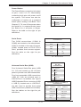
Notes:
•For optimal memory performance, please install DIMM modules in pairs (w/even
number of DIMMs installed).
•All channels in a system will run at the fastest common frequency.
5-9
SUPERWORKSTATION 7047GR-TPRF User's Manual
Populating UDIMM (ECC/Non-ECC) Memory Modules
Intel E5-2600 Series Processor UDIMM Memory Support
Ranks Per
DIMM &
Data Width
Memory Capacity
Per DIMM
Speed (MT/s) and Voltage Validated by Slot per Channel
(SPC) and DIMM Per Channel (DPC)
(See the Note below)
1 Slot Per Channel
2 Slots Per Channel
1DPC
1DPC
2DPC
1.35V
1.5V
1.35V
1.5V
1.35V
1.5V
SRx8
Non-ECC
1GB
2GB
4GB
NA
1066, 1333,
1600
NA
1066,
1333
NA
1066,
1333
DRx8
Non-ECC
2GB
4GB
8GB
NA
1066, 1333,
1600
NA
1066,
1333
NA
1066,
1333
SRx16
Non-ECC
512MB
1GB
2GB
NA
1066, 1333,
1600
NA
1066,
1333
NA
1066,
1333
SRx8 ECC
1GB
2GB
4GB
1066,
1333
1066, 1333,
1600
1066,
1333
1066,
1333
1066
1066,
1333
DRx8 ECC
2GB
4GB
8GB
1066,
1333
1066, 1333,
1600
1066,
1333
1066,
1333
1066
1066,
1333
Note: For detailed information on memory support and updates, please refer to the SMC Recommended
Memory List posted on our website at http://www.supermicro.com/support/resources/mem.cfm.
Populating RDIMM (ECC) Memory Modules
Intel E5-2600 Series Processor RDIMM Memory Support
Ranks
Per
DIMM
& Data
Width
Memory Capacity
Per DIMM
(See the Note Below)
Speed (MT/s) and Voltage Validated by Slot per Channel (SPC) and
DIMM Per Channel (DPC)
1 Slot Per Channel
2 Slots Per Channel
1DPC
1DPC
2DPC
1.35V
1.5V
1.35V
1.5V
1.35V
1.5V
SRx8
1GB
2GB
4GB
1066,
1333
1066, 1333,
1600
1066,
1333
1066, 1333,
1600
1066,
1333
1066, 1333,
1600
DRx8
2GB
4GB
8GB
1066,
1333
1066, 1333,
1600
1066,
1333
1066, 1333,
1600
1066,
1333
1066, 1333,
1600
SRx4
2GB
4GB
8GB
1066,
1333
1066, 1333,
1600
1066,
1333
1066, 1333,
1600
1066,
1333
1066, 1333,
1600
DRx4
4GB
8GB
16GB
1066,
1333
1066, 1333,
1600
1066,
1333
1066, 1333,
1600
1066,
1333
1066, 1333,
1600
QRx4
8GB
16GB
32GB
800
1066
800
1066
800
800
QRx8
4GB
8GB
16GB
800
1066
800
1066
800
800
Note: For detailed information on memory support and updates, please refer to the SMC Recommended
Memory List posted on our website at http://www.supermicro.com/support/resources/mem.cfm.
5-10
Chapter 5: Advanced Serverboard Setup
Populating LRDIMM ECC Memory Modules
Intel E5-2600 Series Processor LRDIMM Memory Support
Ranks Per
DIMM & Data
Width
Memory Capacity
Per DIMM
Speed (MT/s) and Voltage Validated
by Slot per Channel (SPC) and
DIMM Per Channel (DPC)
1 Slot Per
Channel
(See the Note
Below)
1DPC
2 Slots Per
Channel
1DPC and 2DPC
1.35V
1.5V
1.35V
1.5V
QRx4 (DDP)
16GB
32GB
1066,
1333
1066,
1333
1066
1066,
1333
QRx8 (P)
8GB
16GB
1066,
1333
1066,
1333
1066
1066,
1333
Note: For detailed information on memory support and updates, please refer to the
SMC Recommended Memory List posted on our website at http://www.supermicro.
com/support/resources/mem.cfm.
Other Important Notes and Restrictions
•For the memory modules to work properly, please install DIMM modules of the
same type, same speed and same operating frequency. Mixing of RDIMMs,
UDIMMs or LRDIMMs is not allowed. Do not install both ECC and Non-ECC
memory modules on the same motherboard.
•Using DDR3 DIMMs with different operating frequencies is not allowed. All channels in a system will run at the lowest common frequency.
5-11
SUPERWORKSTATION 7047GR-TPRF User's Manual
5-6 Adding PCI Add-On Cards
The 7047GR-TPRF can support four PCI-E 3.0 x16 (may suport four double-width
GPU cards), two PCI-E 3.0 x8 (in x16) and one PCI-E 2.0 x4 (in x8) slots.
Installing an Add-on Card
1. Locate the release tab on the top of the PCI slot bracket. Gently apply
pressure to the middle of the release tab to unlock the PCI slot bracket.
2. Pull the release tab upward.
3. Remove the screw holding the bracket in place and pull the bracket from the
chassis.
4. Install your PCI card or other add-on card into the PCI slot bracket and
serverboard.
5. Push the PCI bracket release tab down until it locks into place with an audible
"click".
6. Secure the PCI card with the screw previously removed from the chassis.
7. Repeat this process with each PCI card you want to install into the chassis.
Figure 5-7: Add-on Card/Expansion Card Port
Press the Middle
of the Release Tab
Lift the
Release Tab
5-12
Chapter 5: Advanced Serverboard Setup
5-7 Serverboard Details
Figure 5-8. X9DRG-QF Layout
(not drawn to scale)
FAN4
USB0/1
COM1
LAN1 PS2 KB/MS
LAN2
JPW4
FANC
BMC
FAND
COM2
X9DRG-QF
Rev. 1.02
USB2/3
VGA
FAN3
LED3
JUIDB
LAN
CTRL
IPMI_LAN
P2-DIMMG1
P2-DIMMG2
P2-DIMMH1
P2-DIMMH2
CPU2 Slot 11 PCI-E 2.0 x 4(IN X8)
CPU2 Slot 9 PCI-E 3.0 x 8
CPU2 Slot 8 PCI-E 3.0 x 16
CPU2 Slot 6 PCI-E 3.0 x 16
CPU1 Slot 4 PCI-E 3.0 x 16
CPU1 Slot 2 PCI-E 3.0 x 16
JPG1JPL1 JPB1JI2C1 JI2C2 JP3 JPME2JPME1JWP1
CPU1 Slot 10 PCI-E 3.0 x 8(IN X16)
JIPMB1
CLOSE 1st
CPU2
CPU2
OPEN 1st
P1-DIMMA1
P1-DIMMA2
P1-DIMMB1
P2-DIMMF2
P2-DIMME2
P2-DIMMF1
P2-DIMME1
P1-DIMMD1
P1-DIMMD2
P1-DIMMC2
P1-DIMMC1
JITP2
JPI2C1
CLOSE 1st
JPW3
J4
JITP1
FAN6/CPU2
LED1
JSTBY1
A
P1-DIMMB2
JWD1
BIOS
USB4
JBAT1
Intel PCH
OPEN 1st
JBT1
FAN1
FAN5/CPU1
FANA
JF1
JPT1
JL1
FANB
SP1
LED2 SP1
JOH1
FAN2
JD1
AUDIO FP
JPW1
JHD_AC1
USB8/9
JPAC1
JSPDIF_IN
USB6/7
S-SATA3
S-SATA2
T-SGPIO1
S-SATA1
I-SATA2
S-SATA0
I-SATA0 JSD1
FAN-I1
JTPM1
I-SATA1
I-SATA3
I-SATA5 I-SATA4 T-SGPIO2
SCU-SGPIO1
JPW2
USB5
BT1
CPU1
Battery
Note: Jumpers not indicated are for test purposes only.
X9DRG-QF Quick Reference
Jumper
Description
Default Setting
JBT1
Clear CMOS
See Section 5-9
JHD_AC1
High Definition Audio Enable/Disable
On (Enabled)
JI2C1/JI2C2
PCI-Exp Slots to SMB Connections
Pins 1-2 (Enabled)
JPAC1
Audio Enable/Disable
Pins 1-2 (Enabled)
JPB1
BMC Enable/Disable
Pins 1-2 (Enabled)
JPG1
VGA Enable/Disable
Pins 1-2 (Enabled)
JPL1
GLAN1/GLAN2 Enable/Disable
Pins 1-2 (Enabled)
JWD1
Watch Dog Timer
Pins 1-2 (Reset)
5-13
SUPERWORKSTATION 7047GR-TPRF User's Manual
Connector
Description
AUDIO_FP
Front Panel Audio Header (Optional)
COM1/COM2
Back Panel COM Port1/Front Accessible COM2 Header
FAN#1~6, FAN
#A~D, FAN11
CPU/System Fan Headers (Fan1~Fan4, Fan5: CPU1 Fan,
Fan6: CPU2 Fan, FanA~FanD, Fan11)
I-SATA 0-5
Two SATA 3.0 Ports (I-SATA 0-1), four SATA 2.0 Ports (ISATA 2-5)
JBAT1
Onboard Battery (See Chpt. 3 for Used Battery Disposal)
JD1
Power LED/Speaker Header (Pins 4~7:External Speaker,
Pins 6/7: Internal Speaker)
JF1
Front Panel Control Header
JIPMB1
4-pin External BMC I2C Header (for an IPMI Card)
JL1
Chassis Intrusion
JOH1
Overheat LED Indicator
JPI C1
Power System Management Bus (SMB) Header
JPW1
24-Pin ATX Main Power Connector
JPW2/JPW3
12V 8-Pin Power Connectors
JPW4
4-Piin Power Connector
JSD1
SATA DOM (Device-On-Module) Power Header
JSPDIF_In
SPDIF (Sony/Philips Digital Interface) In Header
JSTBY1
Standby Power Header
JTPM1
TPM (Trusted Platform Module)/Port 80
JUIDB
UID (Unit Identification) Switch
LAN1/LAN2
G-bit Ethernet Ports 1/2 (See Note Below)
(IPMI) LAN
IPMI_Dedicated LAN
S-SATA 0-3
SATA 2.0 Ports
SP1
Internal Speaker (Onboard Buzzer)
T-SGPIO 1/2
Serial Link General Purpose I/O Headers for SATA Ports
USB 0/1, 2/3
Back Panel USB 0/1, 2/3 Ports
USB4, USB5
Front Accessible Type A USB 4/5 Ports
USB 6/7, 8/9
Front Accessible USB 6/7, 8/9 Headers
2
LED
Description
State
Status
LED1
BMC Heartbeat LED
Green
BMC Normal
LED2
Standby PWR LED
Green: On
SB Power On
LED3
UID Switch LED
Note: LAN connections will be available when two CPUs are installed.
5-14
Chapter 5: Advanced Serverboard Setup
5-8 Connector Definitions
Power Connections
A 24-pin main power supply connector(JPW1),
two 8-pin CPU PWR connectors (JPW2/
JPW3) and a 4-pin PWR connector (JPW4)
are provided on the serverboard. These
power connectors meet the SSI EPS 12V
specification. All these power connectors
must be connected to your power supply
to ensure adequate power supply to your
system. See the table on the right for pin
definitions.
!
Warning: To provide adequate
power supply to the serverboard,
be sure to connect the 24-pin PWR
(JPW1), the 8-pin PWR connectors
(JPW2, JPW3), and the 4-pin PWR
connector (JPW4) to the power
supply. Failure to do so will void
the manufacturer warranty on your
power supply and serverboard.
24-pin Main Power Connector
Pin Definitions
Pin# Definition Pin #
Definition
13
+3.3V
1
+3.3V
14
-12V
2
+3.3V
15
COM
3
COM
16
PS_ON
4
+5V
17
COM
5
COM
18
COM
6
+5V
19
COM
7
COM
20
Res (NC)
8
PWR_OK
21
+5V
9
5VSB
22
+5V
10
+12V
23
+5V
11
+12V
24
COM
12
+3.3V
12V 8-pin PWR
Pin Definitions
12V 4-pin PWR
Pin Definitions
Pins
Definition
Pins
Definition
1~ 4
Ground
1/2
Ground
5~8
+12V
3/4
+12V
Required Connections
NMI Button
The non-maskable interrupt button
header is located on pins 19 and 20
of JF1. Refer to the table on the right
for pin definitions.
NMI Button
Pin Definitions (JF1)
Pin#
Definition
19
Control
20
Ground
Power LED
Pin Definitions (JF1)
Power LED
The Power LED connection is located
on pins 15 and 16 of JF1. Refer to the
table on the right for pin definitions.
HDD LED
The HDD LED connection is located on
pins 13 and 14 of JF1. Attach a cable
here to indicate HDD activity. See the
table on the right for pin definitions.
5-15
Pin#
Definition
15
3.3V
16
PWR LED
HDD LED
Pin Definitions (JF1)
Pin#
Definition
13
3.3V Standby
14
HD Active
SUPERWORKSTATION 7047GR-TPRF User's Manual
NIC1/NIC2 LED Indicators
GLAN1/2 LED