1
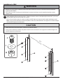
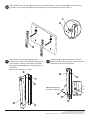
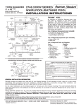
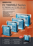
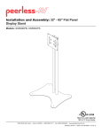
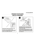
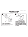
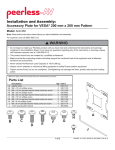
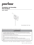
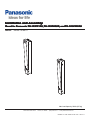
Installation and Assembly:
Mount for Panasonic TH-103PF12U, TH-103PH9UK, and TH-103VX200U
Model: PANA-103MTV
Max Load Capacity: 500 lb (227 kg)
2300 White Oak Circle. • Aroura, IL 60502 • (800) 856-2112 • www.peerlessmounts.com
ISSUED: 10-18-06 SHEET #: 202-9172-3 03-24-11
Note: Read entire instruction sheet before you start installation and assembly.
WARNING
• Do not begin to install your Panasonic product until you have read and understood the instructions and warnings
contained in this Installation Sheet. If you have any questions regarding any of the instructions or warnings, please
call Panasonic Customer Support.
• This product should only be installed by a qualified professional.
• Make sure that the supporting surface will safely support the combined load of the equipment and all attached hardware and components.
• Never exceed the Maximum Load Capacity of 500 lb (227 kg).
• Always use an assistant or mechanical lifting equipment to safely lift and position equipment.
• Tighten screws firmly, but do not overtighten. Overtightening can damage the items, greatly reducing their holding
power.
A
Parts ListTS LIST
Description
Qty.
B
Part #
A
wall plate
2
201-1201
B
tilt plate
2
201-1203
C
lock tab
4
201-1204
D
washer
8
540-1005
E
clevis pin
4
560-2115
F
cotter pin
4
560-2157
G
M5 x 6 mm phillips screw
8
520-9504
H
nylock nut
8
530-9412
I
SAE washer
8
540-9448
J
M10 x 20 mm socket screw
8
5S1-M10-A20
C
D
G
H
J
I
F
E
For customer care call (800) 865-2112 or (708) 865-8870.
This item was manufactured for Panasonic by Peerless Industries.
2 of 4
ISSUED: 10-18-06 SHEET #: 202-9172-3 03-24-11
Installation to Wall
WARNING
• Installer must verify that the supporting surface will safely support four times the combined weight of all attached
equipment and hardware.
• Only meant for surface mounting to the desired wall, recessed mounting or any other application please contact
customer care.
Attach wall plates (A) to supporting surface. Distance between centers of wall plates (A) must be 59.5" (1511mm)
and wall plates (A) must be level with one another.
1
M10 x 20 mm socket screws (J), nylock nuts (H), and SAE wahers (I) may be used to attach wall plates to wall.
Note: If using custom fasteners to attach wall plates to wall be sure that fasteners can support the combined weight
of all attached equipment and hardware.
CAUTION
• If wall mounts are not level and square, mount will not function properly.
• If using custom fasteners to attach wall plates to wall be sure that fasteners can support the combined weight of all
attached equipment and hardware.
J
59
.5"
(15
11
mm
)
I
H
A
A
This item was manufactured for Panasonic by Peerless Industries.
3 of 4
ISSUED: 10-18-06 SHEET #: 202-9172-3 03-24-11
2
Slide keyhole slots of tilt plates (B) onto spacers provided with screen. Secure tilt plates (B) to screen by using
eight M5 x 6 mm screws (G) to attach four locking tabs (C) to keyhole slots as shown in Detail 1.
C
G
DETAIL 1
B
3
Attach clevis pin to wall plates (A) using two
washers (D). Secure clevis pin (E) with cotter pin (F)
as show below. Attach tilt plates (B) to wall plates
(A) by sliding tilt plate (B) onto clevis pin (E) per set
of brackets.
4
Set tilt plate (B) to desired tilt shown in detail 2.
Secure with one clevis pin (E), two washers (D), and
one cotter pin (F) per set of brackets.
Note: Screen not shown for clarity.
E
B
A
F
D
F
Note: Side clearance is
needed to install pin
0°
2°
4°
E
DETAIL 2
D
B
D
A
This item was manufactured for Panasonic by Peerless Industries.
4 of 4
ISSUED: 10-18-06 SHEET #: 202-9172-3 03-24-11
© 2011 Peerless Industries, Inc. All rights reserved.
Peerless is a registered trademark of Peerless Industries, Inc.
All other brand and product names are trademarks or registered trademarks of their respective owners.