1
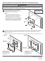
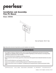
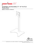
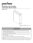
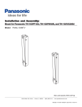
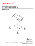
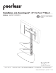
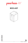
Installation and Assembly:
Accessory Plate for VESA® 200 mm x 200 mm Pattern
Model: ACC450
Note: Read entire instruction sheet before you start installation and assembly.
For customer care call (800) 865-2112.
WARNING
• Do not begin to install your Peerless product until you have read and understood the instructions and warnings
contained in this Installation Sheet. If you have any questions regarding any of the instructions or warnings, please
call Peerless customer care at 1-800-865-2112.
• This product should only be installed by a qualified professional.
• Make sure that the supporting surface will safely support the combined load of the equipment and all attached
hardware and components.
• Never exceed the Maximum Load Capacity of 150 lb (68 kg).
• Always use an assistant or mechanical lifting equipment to safely lift and position equipment.
• Tighten screws firmly, but do not overtighten. Overtightening can damage the items, greatly reducing their holding
power.
Before you begin, make sure all parts shown are included with your product.
Parts List
A
B
C
D
E
F
G
H
I
J
B
Description
adapter plate
M6 x 12 mm phillips screw
M6 x 12 mm serrated washer head socket pin screw
M6 x 20 mm phillips screw
M6 x 20 mm serrated washer head socket pin screw
M8 x 10 mm phillips screw
M8 x 10 mm serrated washer head socket pin screw
M5 x 6 mm phillips screw
M5 x 6 mm serrated washer head socket pin screw
4 mm security allen wrench
Qty
1
4
4
4
4
4
4
4
4
1
Part #
095-1721
520-1128
510-1050
520-9402
510-9554
520-1605
520-1706
520-1023
520-1114
560-9646
A
H
C
D
E
G
F
I
1 of 2
J
ISSUED: 10-13-05 SHEET #: 202-9039-2 08-16-11
Attaching Adapter Plate to Display with VESA 200 x 200 Mounting Pattern
WARNING
• If screws don't get three complete turns in the display inserts or if screws bottom out and adapter plate is still not
tightly secured, damage may occur to display or product may fail.
1
Choose hole pattern as shown. Attach adapter
plate (A) to back of display using four M6 x 12 mm
screws (B) or M8 x 10 mm screws (F).
Note: Flat panel display
may appear slightly
different than illustrated.
Notes:
• If screw (B) gets less than three threads of
engagement, attach adapter plate (A) to back of
display using four M6 x 20 mm screws (D).
• For security option, use M6 x 12 mm screws (C)
in place of (B), M6 x 20 mm screws (E) in place of
(D), and M8 x 10 mm screws (G) in place of (F).
Tighten security screws using allen wrench (J).
A
2
Thread two M5 x 6 mm screws (H), leaving .25" exposed thread, into top holes of adapter plate (A). Hook adapter
plate onto mounting plate, and secure using bottom two M5 x 6 mm screws as shown in figures 2.1 and 2.2.
Tighten all four screws.
Note: For security option, use M5 x 6 mm screws (I) in place of (H). Tighten security screws using allen wrench (J).
fig. 2.1
fig. 2.2
A
H or I
H or I
MOUNTING PLATE
(NOTE: MOUNTING PLATE
SHOWN WITHOUT FULL
WALL MOUNT ASSEMBLY
FOR CLARITY)
MOUNTING PLATE
(NOTE: MOUNTING PLATE
SHOWN WITHOUT FULL
WALL MOUNT ASSEMBLY
FOR CLARITY)
2 of 2
ISSUED: 10-13-05 SHEET #: 202-9039-2 08-16-11
© 2011, Peerless Industries, Inc. All rights reserved.
All other brand and product names are trademarks or registered trademarks of their respective owners.
Peerless Industries, Inc.
2300 White Oak Circle
Aurora, Il 60502
www.peerlessmounts.com