1
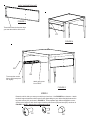
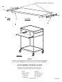
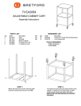
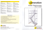
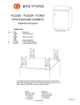
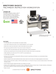
ECILS2 / ECILS2M
NOTEBOOK-DATA
PROJECTION CART
Assembly Instructions
PARTS LIST
Qty
2
1
2
1
1
1
1
2
2
1
1
Part#
010-1863
010-4514
010-4507
022-2311
022-2310
022-2313
022-2312
015-0002
015-0003
030-1191
ES
HARDWARE LIST
Description
Top & Bottom Shelves
Slide Out Shelf
Shelf Support Brackets
Right Front Leg
Left Front Leg
Right Rear Leg
Left Rear Leg
4" Casters w/o Lock
4" Casters w/ Lock
14" Full Extension Slide
Electrical Unit - ECILS2M ONLY
LR
Ref
AA
BB
CC
DD
EE
FF
Qty
16
16
8
8
4
4
1
Part#
030-0300-10T
030-0002
030-0304
030-1228
030-1203
02236
010-1106
Description
5/8" Square Head Bolts
5/16-18 Hex Serrated Nuts
1/4-20 x 5/8" Combo Screws
8-32 x 1/4" Truss Screws
#8-32 Acorn Nuts
8-32 Flange Whis Lock Nuts
Hex Wrench
TOOLS REQUIRED
Hex Wrench (Provided)
Phillips Screwdriver
Rubber Mallet
RR
TOP
BOTTOM
FIGURE 1
Align shelf embossed mounting
hole with leg mounting bracket.
2 corners each shelf.
FIGURE 2
STEP 1
Lay two legs on a carpeted surface with the six top holes facing up and the brackets facing up
and in as shown in Figure 1. Slide the top and bottom shelves (with 4 square holes toward
front) onto the legs so that the brackets are inside the shelves as shown in Figure 2.
Align shelf embossed mounting
hole with leg mounting bracket.
2 corners each shelf.
STEP 2
Slide the remaining two legs onto the shelves
so that the brackets are inside the shelves.
AA
BB
STEP 3
Secure shelves and legs together with bolts (AA)
and nuts (BB) in each corner as shown.
STEP 4
BB
AA
Insert each caster into the bottom of each leg. If
caster does not insert easily, use a rubber mallet to
tap caster in place. Once casters are SECURELY in
place, stand unit upright.
SHELF SUPPORT BRACKET
FIGURE 3
These holes need to face the edge
you want the shelf to slide out on.
CC
FIGURE 4
EE
DD
To access the correct
holes, slide inner piece
out slightly.
Attach rear screw
& nut FIRST.
FIGURE 5
STEP 5
Determine which side you want your shelf to pull out from. Use FIGURE 3 as reference. Attach
the shelf support brackets to either set of holes (depending on your desired height) between the
legs with screws (CC) as shown in FIGURE 4. Then separate each slide and attach the outer
section to the inside of each shelf support bracket with screws (DD) and nuts (EE) as shown in
FIGURE 5. NOTE: Attach rear screw and nut first.
CC
DD
EE
Alternate Mounting Slot, if Necessary
FIGURE 6
FF
DD
FIGURE 7
STEP 6
Attach the remaining slide pieces to the pull out shelf with screws (DD) and nuts
(FF) as shown in FIGURE 6. Then slide shelf into cart as shown in FIGURE 7.
E-UNIT ASSEMBLY FOR MODEL ECILS2M
Remove wing nuts from the back of the electrical unit.
Position E-uni on shelf side and secure with wing nuts.
Bretford
11000 Seymour Avenue
Franklin Park, IL 60131
TEL: 847.678.2545
800.521.9614
FAX: 847.678.0852
800.343.1779
Bretford Ltd.
Technology House
7 Lake End Court, Taplow
Bucks SL6 0JQ England
TEL: 01628 603558
FAX: 01628 604923
www.bretford.com
Part # 031-6632
Rev. 11.13.09 CZ