1
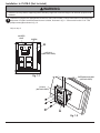
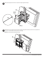
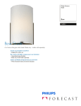
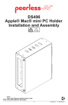
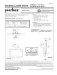
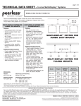
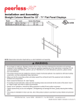
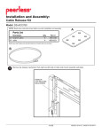
Installation and Assembly:
Custom Mac Mini PC Holder
Model: DS495
Maximum Load Capacity: 10 lb (4.5 kg)
NOTE: Read entire instruction sheet before you start installation and assembly.
WARNING
• Do not begin to install your Peerless product until you have read and understood the instructions and warnings
contained in this Installation Sheet. If you have any questions regarding any of the instructions or warnings, please
call Peerless customer care at 1-800-865-2112.
• This product should only be installed by someone of good mechanical aptitude, has experience with basic building
construction, and fully understands these instructions.
• Make sure that the supporting surface will safely support the combined load of the equipment and all attached hardware and components.
• Never exceed the Maximum Load Capacity.
• Always use an assistant or mechanical lifting equipment to safely lift and position equipment.
• Tighten screws firmly, but do not overtighten. Overtightening can damage the items, greatly reducing their holding
power.
3215 W. North Ave. • Melrose Park, IL 60160 • (800) 865-2112 or (708) 865-8870 • Fax: (708) 865-2941 • www.peerlessmounts.com
Before you begin, make sure all parts shown are included with your product.
Parts may appear slightly different than illustrated.
A
Parts List
A
B
C
D
E
F
G
H
B
F
Description
computer box
alternate support bracket
box cover
#10 x 1/2" TEK phillips screw
M4 x 10 mm serrated washer head socket pin screw
4mm security allen wrench
cable tie
M5 x 10 mm type-F socket pin screw
C
Qty.
1
4
1
4
2
1
6
8
D
Part #
124-1139
124-1141
124-1140
520-1320
510-1060
560-9646
560-9711
520-1164
E
G
H
Parts may appear slightly different than illustrated.
2 of 5
ISSUED: 03-05-09 SHEET #: 125-9053-1
Installation to PLCM-2 (Not Included)
WARNING
• Installer must verify that the supporting surface will safely support the combined weight of all attached equipment and
hardware.
1
Hold back of computer box (A) against the back of PLCM-2 (not included). Line up locator hole of computer box (A)
with screw of PLCM-2 so that the head of screw is visible, as shown in fig. 1.1. Secure with four #10 x 1/2" TEK
phillips screws (D) as shown in fig. 1.2.
Skip to step 2.
LOCATER
HOLE
SCREW
A
PLCM-2
(NOT INCLUDED)
fig. 1.1
EXTENSION COLUMN
(NOT INCLUDED)
PLCM-2
(NOT INCLUDED)
D
A
fig. 1.2
3 of 5
ISSUED: 03-05-09 SHEET #: 125-9053-1
Installation to Supporting Surface
WARNING
• Installer must verify that the supporting surface will safely support the combined weight of all attached equipment and
hardware.
1
There are eight mounting places for the alternate support brackets (B) as shown in fig. 1.3. Determined the locations
for alternate support brackets (B) according to supporting surface. Using allen wrench (F), fasten two or four alternate
support brackets (B) to computer box (A) with two M5 x 10 mm type-F socket pin screws (H) for each alternate
support bracket (B). Use installer supplied screws/fasteners to attach alternate support brackets (B) to supporting
surface.
NOTE: For each alternate support brackets (B), two screws must be used for attachment to supporting surface.
A
H
B
fig. 1.3
B
A
fig. 1.4
4 of 5
ISSUED: 03-05-09 SHEET #: 125-9053-1
2
Attach power supply and mini mac to computer box (A) using cable ties (G).
A
POWER
SUPPLY
G
MINI MAC
3
Slide tabs of box cover (C) into slots of computer box (A). Using allen wrench (F), secure box cover (C) with two
M4 x 10 mm serrated washer head socket pin screws (E).
NOTE: Box cover (C) can be oriented left or right.
A
C
E
5 of 5
ISSUED: 03-05-09 SHEET #: 125-9053-1
© 2007, Peerless Industries, Inc. All rights reserved.
All other brand and product names are trademarks or registered trademarks of their respective owners.