1
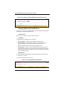
SSE-G2252 Switches
52-Port Layer 2 Gigabit Ethernet Switch
SSE-G2252
SSE-G2252P Switches
52-Port Layer 2 Gigabit Ethernet Switch with
48 PoE-Capable Ports
SSE-G2252P
USER’S MANUAL
Revison 1.0
i
SSE-G2252/SSE-G2252P Switches USER’S MANUAL
The information in this USER’S MANUAL has been carefully reviewed and is believed to be accurate. The
vendor assumes no responsibility for any inaccuracies that may be contained in this document, makes no
commitment to update or to keep current the information in this manual, or to notify any person or
organization of the updates. Please Note: For the most up-to-date version of this manual, please see
our web site at www.supermicro.com.
Super Micro Computer, Inc. (“Supermicro”) reserves the right to make changes to the product described
in this manual at any time and without notice. This product, including software, if any, and documentation
may not, in whole or in part, be copied, photocopied, reproduced, translated or reduced to any medium or
machine without prior written consent.
IN NO EVENT WILL SUPERMICRO BE LIABLE FOR DIRECT, INDIRECT, SPECIAL, INCIDENTAL,
SPECULATIVE OR CONSEQUENTIAL DAMAGES ARISING FROM THE USE OR INABILITY TO USE
THIS PRODUCT OR DOCUMENTATION, EVEN IF ADVISED OF THE POSSIBILITY OF SUCH
DAMAGES. IN PARTICULAR, SUPERMICRO SHALL NOT HAVE LIABILITY FOR ANY HARDWARE,
SOFTWARE, OR DATA STORED OR USED WITH THE PRODUCT, INCLUDING THE COSTS OF
REPAIRING, REPLACING, INTEGRATING, INSTALLING OR RECOVERING SUCH HARDWARE,
SOFTWARE, OR DATA.
Any disputes arising between manufacturer and customer shall be governed by the laws of Santa Clara
County in the State of California, USA. The State of California, County of Santa Clara shall be the
exclusive venue for the resolution of any such disputes. Super Micro's total liability for all claims will not
exceed the price paid for the hardware product.
FCC Statement: This equipment has been tested and found to comply with the limits for a Class A digital
device pursuant to Part 15 of the FCC Rules. These limits are designed to provide reasonable protection
against harmful interference when the equipment is operated in a commercial environment. This
equipment generates, uses, and can radiate radio frequency energy and, if not installed and used in
accordance with the manufacturer’s instruction manual, may cause harmful interference with radio
communications. Operation of this equipment in a residential area is likely to cause harmful interference,
in which case you will be required to correct the interference at your own expense.
California Best Management Practices Regulations for Perchlorate Materials: This Perchlorate warning
applies only to products containing CR (Manganese Dioxide) Lithium coin cells. Perchlorate
Material-special handling may apply. See www.dtsc.ca.gov/hazardouswaste/perchlorate for further
details.
WARNING: HANDLING OF LEAD SOLDER MATERIALS USED IN THIS
PRODUCT MAY EXPOSE YOU TO LEAD, A CHEMICAL KNOWN TO THE
STATE OF CALIFORNIA TO CAUSE BIRTH DEFECTS AND OTHER
REPRODUCTIVE HARM.
Manual Revison 1.0
Release Date: March 22, 2012
Unless you request and receive written permission from Super Micro Computer, Inc., you may not copy
any part of this document.
Information in this document is subject to change without notice. Other products and companies referred
to herein are trademarks or registered trademarks of their respective companies or mark holders.
Copyright © 2012 by Super Micro Computer, Inc.
All rights reserved.
Printed in the United States of America
ii
Preface
About this Manual
This manual is written for professional system integrators, Information Technology
professionals, service personnel, technicians and network administrators who are
responsible for installing and setting up network equipment; consequently, it assumes a
basic working knowledge of LANs (Local Area Networks). It provides information for the
installation and use of Supermicro's SSE-G2252 and SSE-G2252P switches.
Installation and maintenance should be performed by experienced professionals only.
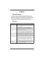
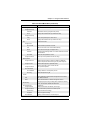
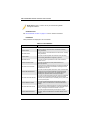
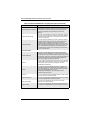
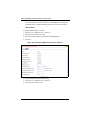
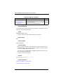
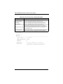
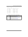
Glossary
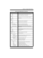
Glossary Term
Description
ACL
Access Control List. ACLs can limit network traffic and restrict access to
certain users or devices by checking each packet for certain IP or MAC
(i.e., Layer 2) information.
ARP
Address Resolution Protocol converts between IP addresses and MAC
(hardware) addresses. ARP is used to locate the MAC address
corresponding to a given IP address. This allows the switch to use IP
addresses for routing decisions and the corresponding MAC addresses to
forward packets from one hop to the next.
BOOTP
Boot Protocol. BOOTP is used to provide bootup information for network
devices, including IP address information, the address of the TFTP server
that contains the devices system files, and the name of the boot file.
CoS
Class of Service is supported by prioritizing packets based on the required
level of service, and then placing them in the appropriate output queue.
Data is transmitted from the queues using weighted round-robin service to
enforce priority service and prevent blockage of lower-level queues.
Priority may be set according to the port default, the packet’s priority bit (in
the VLAN tag), TCP/UDP port number, IP Precedence bit, or DSCP priority
bit.
DHCP
Dynamic Host Control Protocol. Provides a framework for passing
configuration information to hosts on a TCP/IP network. DHCP is based on
the Bootstrap Protocol (BOOTP), adding the capability of automatic
allocation of reusable network addresses and additional configuration
options.
DHCP Snooping
A technique used to enhance network security by snooping on DHCP
server messages to track the physical location of hosts, ensure that hosts
only use the IP addresses assigned to them, and ensure that only
authorized DHCP servers are accessible.
iii
SSE-G2252/SSE-G2252P Switches USER’S MANUAL
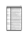
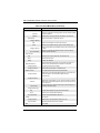
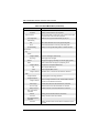
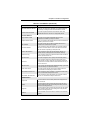
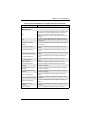
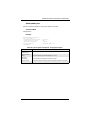
Glossary Term
Description
DiffServ
Differentiated Services provides quality of service on large networks by
employing a well-defined set of building blocks from which a variety of
aggregate forwarding behaviors may be built. Each packet carries
information (DS byte) used by each hop to give it a particular forwarding
treatment, or per-hop behavior, at each network node. DiffServ allocates
different levels of service to users on the network with mechanisms such
as traffic meters, shapers/droppers, packet markers at the boundaries of
the network.
DNS
Domain Name Service. A system used for translating host names for
network nodes into IP addresses.
DSCP
Differentiated Services Code Point Service. DSCP uses a six-bit tag to
provide for up to 64 different forwarding behaviors. Based on network
policies, different kinds of traffic can be marked for different kinds of
forwarding. The DSCP bits are mapped to the Class of Service categories,
and then into the output queues.
EAPOL
Extensible Authentication Protocol over LAN. EAPOL is a client
authentication protocol used by this switch to verify the network access
rights for any device that is plugged into the switch. A user name and
password is requested by the switch, and then passed to an authentication
server (e.g., RADIUS) for verification. EAPOL is implemented as part of
the IEEE 802.1X Port Authentication standard.
EUI
Extended Universal Identifier is an address format used by IPv6 to identify
the host portion of the network address. The interface identifier in EUI
compatible addresses is based on the link-layer (MAC) address of an
interface. Interface identifiers used in global unicast and other IPv6
address types are 64 bits long and may be constructed in the EUI-64
format. The modified EUI-64 format interface ID is derived from a 48-bit
link-layer address by inserting the hexadecimal number FFFE between the
upper three bytes (OUI field) and the lower 3 bytes (serial number) of the
link layer address. To ensure that the chosen address is from a unique
Ethernet MAC address, the 7th bit in the high-order byte is set to 1
(equivalent to the IEEE Global/Local bit) to indicate the uniqueness of the
48-bit address.
GARP
Generic Attribute Registration Protocol. GARP is a protocol that can be
used by endstations and switches to register and propagate multicast
group membership information in a switched environment so that multicast
data frames are propagated only to those parts of a switched LAN
containing registered endstations. Formerly called Group Address
Registration Protocol.
GMRP
Generic Multicast Registration Protocol. GMRP allows network devices to
register end stations with multicast groups. GMRP requires that any
participating network devices or end stations comply with the IEEE 802.1p
standard.
GVRP
GARP VLAN Registration Protocol. Defines a way for switches to
exchange VLAN information in order to register necessary VLAN members
on ports along the Spanning Tree so that VLANs defined in each switch
can work automatically over a Spanning Tree network.
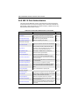
IEEE 802.1D
Specifies a general method for the operation of MAC bridges, including the
Spanning Tree Protocol.
iv
Preface
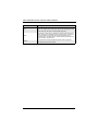
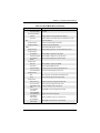
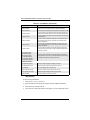
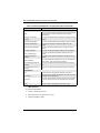
Glossary Term
Description
IEEE 802.1Q
VLAN Tagging—Defines Ethernet frame tags which carry VLAN
information. It allows switches to assign endstations to different virtual
LANs, and defines a standard way for VLANs to communicate across
switched networks.
IEEE 802.1p
An IEEE standard for providing quality of service (QoS) in Ethernet
networks. The standard uses packet tags that define up to eight traffic
classes and allows switches to transmit packets based on the tagged
priority value.
IEEE 802.1s
An IEEE standard for the Multiple Spanning Tree Protocol (MSTP) which
provides independent spanning trees for VLAN groups.
IEEE 802.1w
An IEEE standard for the Rapid Spanning Tree Protocol (RSTP) which
reduces the convergence time for network topology changes to about 10%
of that required by the older IEEE 802.1D STP standard. (Now
incorporated in IEEE 802.1D-2004)
IEEE 802.1X
Port Authentication controls access to the switch ports by requiring users
to first enter a user ID and password for authentication.
IEEE 802.3ac
Defines frame extensions for VLAN tagging.
IEEE 802.3x
Defines Ethernet frame start/stop requests and timers used for flow control
on full-duplex links. (Now incorporated in IEEE 802.3-2002)
IGMP
Internet Group Management Protocol. A protocol through which hosts can
register with their local router for multicast services. If there is more than
one multicast switch/router on a given subnetwork, one of the devices is
made the “querier” and assumes responsibility for keeping track of group
membership.
IGMP Query
On each subnetwork, one IGMP-capable device will act as the querier —
that is, the device that asks all hosts to report on the IP multicast groups
they wish to join or to which they already belong. The elected querier will
be the device with the lowest IP address in the subnetwork.
IGMP Proxy
Proxies multicast group membership information onto the upstream
interface based on IGMP messages monitored on downstream interfaces,
and forwards multicast traffic based on that information. There is no need
for multicast routing protocols in an simple tree that uses IGMP Proxy.
IGMP Snooping
Listening to IGMP Query and IGMP Report packets transferred between IP
Multicast Routers and IP Multicast host groups to identify IP Multicast
group members.
In-Band Management
Management of the network from a station attached directly to the network.
IP Multicast Filtering
A process whereby this switch can pass multicast traffic along to
participating hosts.
IP Precedence
The Type of Service (ToS) octet in the IPv4 header includes three
precedence bits defining eight different priority levels ranging from highest
priority for network control packets to lowest priority for routine traffic. The
eight values are mapped one-to-one to the Class of Service categories by
default, but may be configured differently to suit the requirements for
specific network applications.
LACP
Link Aggregation Control Protocol. Allows ports to automatically negotiate
a trunked link with LACP-configured ports on another device.
Layer 2
Data Link layer in the ISO 7-Layer Data Communications Protocol. This is
related directly to the hardware interface for network devices and passes
on traffic based on MAC addresses.
v
SSE-G2252/SSE-G2252P Switches USER’S MANUAL
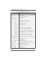
Glossary Term
Description
Link Aggregation
See Port Trunk.
LLDP
Link Layer Discovery Protocol is used to discover basic information about
neighboring devices in the local broadcast domain by using periodic
broadcasts to advertise information such as device identification,
capabilities and configuration settings.
MD5
MD5 Message-Digest is an algorithm that is used to create digital
signatures. It is intended for use with 32 bit machines and is safer than the
MD4 algorithm, which has been broken. MD5 is a one-way hash function,
meaning that it takes a message and converts it into a fixed string of digits,
also called a message digest.
MIB
Management Information Base. An acronym for Management Information
Base. It is a set of database objects that contains information about a
specific device.
MSTP
Multiple Spanning Tree Protocol can provide an independent spanning tree
for different VLANs. It simplifies network management, provides for even
faster convergence than RSTP by limiting the size of each region, and
prevents VLAN members from being segmented from the rest of the group.
MRD
Multicast Router Discovery is a A protocol used by IGMP snooping and
multicast routing devices to discover which interfaces are attached to
multicast routers. This process allows IGMP-enabled devices to determine
where to send multicast source and group membership messages.
Multicast Switching
A process whereby the switch filters incoming multicast frames for services
for which no attached host has registered, or forwards them to all ports
contained within the designated multicast VLAN group.
MVR
Multicast VLAN Registration is a method of using a single network-wide
multicast VLAN to transmit common services, such as such as television
channels or video-on-demand, across a service-provider’s network. MVR
simplifies the configuration of multicast services by using a common VLAN
for distribution, while still preserving security and data isolation for
subscribers residing in both the MVR VLAN and other standard or private
VLAN groups.
NTP
Network Time Protocol provides the mechanisms to synchronize time
across the network. The time servers operate in a
hierarchical-master-slave configuration in order to synchronize local clocks
within the subnet and to national time standards via wire or radio.
Out-of-Band Management
Management of the network from a station not attached to the network.
Port Authentication
See IEEE 802.1X.
Port Mirroring
A method whereby data on a target port is mirrored to a monitor port for
troubleshooting with a logic analyzer or RMON probe. This allows data on
the target port to be studied unobstructively.
Port Trunk
Defines a network link aggregation and trunking method which specifies
how to create a single high-speed logical link that combines several
lower-speed physical links.
Private VLANs
Private VLANs provide port-based security and isolation between ports
within the assigned VLAN. Data traffic on downlink ports can only be
forwarded to, and from, uplink ports.
vi
Preface
Glossary Term
Description
QinQ
QinQ tunneling is designed for service providers carrying traffic for multiple
customers across their networks. It is used to maintain customer-specific
VLAN and Layer 2 protocol configurations even when different customers
use the same internal VLAN IDs.
QoS
Quality of Service. QoS refers to the capability of a network to provide
better service to selected traffic flows using features such as data
prioritization, queuing, congestion avoidance and traffic shaping. These
features effectively provide preferential treatment to specific flows either by
raising the priority of one flow or limiting the priority of another flow.
RADIUS
Remote Authentication Dial-in User Service. RADIUS is a logon
authentication protocol that uses software running on a central server to
control access to RADIUS-compliant devices on the network.
RMON
Remote Monitoring. RMON provides comprehensive network monitoring
capabilities. It eliminates the polling required in standard SNMP, and can
set alarms on a variety of traffic conditions, including specific error types.
RSTP
Rapid Spanning Tree Protocol. RSTP reduces the convergence time for
network topology changes to about 10% of that required by the older IEEE
802.1D STP standard.
SMTP
Simple Mail Transfer Protocol is a standard host-to-host mail transport
protocol that operates over TCP, port 25.
SNMP
Simple Network Management Protocol. The application protocol in the
Internet suite of protocols which offers network management services.
SNTP
Simple Network Time Protocol allows a device to set its internal clock
based on periodic updates from a Network Time Protocol (NTP) server.
Updates can be requested from a specific NTP server, or can be received
via broadcasts sent by NTP servers.
SSH
Secure Shell is a secure replacement for remote access functions,
including Telnet. SSH can authenticate users with a cryptographic key, and
encrypt data connections between management clients and the switch.
STA
Spanning Tree Algorithm is a technology that checks your network for any
loops. A loop can often occur in complicated or backup linked network
systems. Spanning Tree detects and directs data along the shortest
available path, maximizing the performance and efficiency of the network.
TACACS+
Terminal Access Controller Access Control System Plus. TACACS+ is a
logon authentication protocol that uses software running on a central
server to control access to TACACS-compliant devices on the network.
TCP/IP
Transmission Control Protocol/Internet Protocol. Protocol suite that
includes TCP as the primary transport protocol, and IP as the network
layer protocol.
Telnet
Defines a remote communication facility for interfacing to a terminal device
over TCP/IP.
TFTP
Trivial File Transfer Protocol. A TCP/IP protocol commonly used for
software downloads.
UDP
User Datagram Protocol. UDP provides a datagram mode for
packet-switched communications. It uses IP as the underlying transport
mechanism to provide access to IP-like services. UDP packets are
delivered just like IP packets – connection-less datagrams that may be
discarded before reaching their targets. UDP is useful when TCP would be
too complex, too slow, or just unnecessary.
vii
SSE-G2252/SSE-G2252P Switches USER’S MANUAL
Glossary Term
Description
UTC
Universal Time Coordinate. UTC is a time scale that couples Greenwich
Mean Time (based solely on the Earth’s rotation rate) with highly accurate
atomic time. The UTC does not have daylight saving time.
VLAN
Virtual LAN. A Virtual LAN is a collection of network nodes that share the
same collision domain regardless of their physical location or connection
point in the network. A VLAN serves as a logical workgroup with no
physical barriers, and allows users to share information and resources as
though located on the same LAN.
XModem
A protocol used to transfer files between devices. Data is grouped in
128-byte blocks and error-corrected.
viii
Table of Contents
Chapter 1 Introduction....................................................................... 1-1
1-1 Key Features ...................................................................................... 1-1
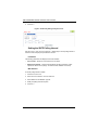
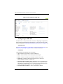
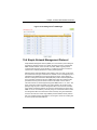
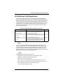
1-2 Description of Software Features ................................................... 1-2
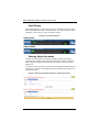
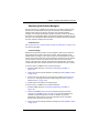
Configuration Backup and Restore ......................................................... 1-2
Authentication ......................................................................................... 1-3
Access Control Lists ............................................................................... 1-3
Port Configuration ................................................................................... 1-3
Port Mirroring .......................................................................................... 1-3
Port Trunking........................................................................................... 1-3
Rate Limiting ........................................................................................... 1-4
Storm Control .......................................................................................... 1-4
Static Addresses ..................................................................................... 1-4
IEEE 802.1D Bridge................................................................................ 1-4
Store-and-Forward Switching.................................................................. 1-4
Spanning Tree Algorithm......................................................................... 1-4
Virtual LANs ............................................................................................ 1-5
Traffic Prioritization ................................................................................. 1-6
Quality of Service.................................................................................... 1-6
Multicast Filtering .................................................................................... 1-6
System Defaults ...................................................................................... 1-6
Chapter 2 System Safety .................................................................. 2-1
2-1 Electrical Safety Precautions........................................................... 2-1
2-2 General Safety Precautions............................................................. 2-2
2-3 Electrostatic Discharge Precautions .............................................. 2-2
2-4 Operating Precautions ...................................................................... 2-3
2-5 Compliances and Safety .................................................................. 2-3
FCC Class A ........................................................................................... 2-3
Industry Canada - Class A ...................................................................... 2-3
CE Mark Declaration of Conformance for EMI and Safety (EEC)........... 2-4
Safety Compliance.................................................................................. 2-5
Power Cord Safety.................................................................................. 2-5
France and Peru only.............................................................................. 2-6
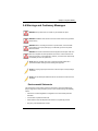
2-6 Warnings and Cautionary Messages ............................................. 2-9
Environmental Statements ...................................................................... 2-9
End of Product Life Span ...................................................................... 2-10
ix
SSE-G2252/SSE-G2252P Switches USER’S MANUAL
Manufacturing Materials........................................................................ 2-10
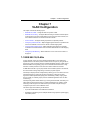
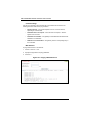
Chapter 3 Initial Configuration ..................................................... 3-1
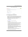
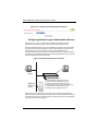
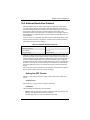
3-1 Connecting to the Switch ................................................................. 3-1
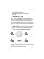
Configuration Options ............................................................................. 3-1
Required Connections ............................................................................ 3-2
Remote Connections .............................................................................. 3-3
3-2 Basic Configuration ........................................................................... 3-4
Console Connection................................................................................ 3-4
Setting Passwords .................................................................................. 3-4
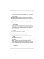
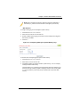
Setting an IP Address ............................................................................. 3-5
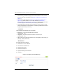
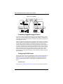
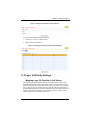
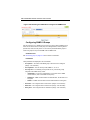
Manual Configuration ........................................................................... 3-5
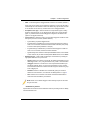
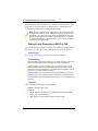
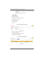
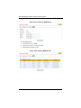
Dynamic Configuration......................................................................... 3-8
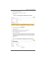
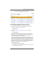
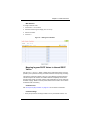
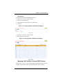
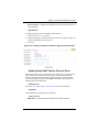
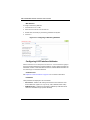
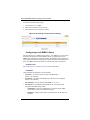
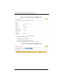
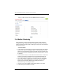
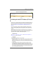
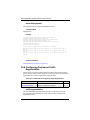
Downloading a Configuration File Referenced by a DHCP Server....... 3-10
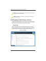
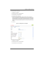
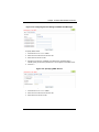
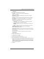
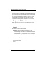
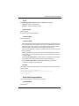
Enabling SNMP Management Access .................................................. 3-12
Community Strings (for SNMP version 1 and 2c Clients)................... 3-13
Trap Receivers ................................................................................... 3-13
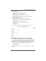
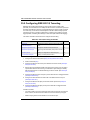
Configuring Access for SNMP Version 3 Clients................................ 3-14
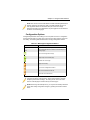
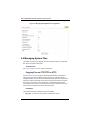
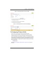
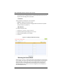
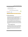
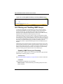
3-3 Managing System Files .................................................................. 3-14
Saving or Restoring Configuration Settings .......................................... 3-15
Chapter 4 Using the Web Interface........................................... 4-1
4-1 Connecting to the Web Interface .................................................... 4-1
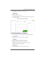
4-2 Navigating the Web Browser Interface .......................................... 4-2
Home Page ............................................................................................. 4-2
Configuration Options ............................................................................. 4-3
Panel Display .......................................................................................... 4-4
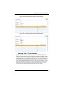
Showing Status Information .................................................................... 4-4
Main Menu ............................................................................................. 4-5
Chapter 5 Basic Management Tasks ........................................ 5-1
5-1 Displaying System Information ....................................................... 5-1
5-2 Displaying Switch Hardware/Software Versions ......................... 5-2
5-3 Configuring Support for Jumbo Frames ........................................ 5-3
5-4 Displaying Bridge Extension Capabilities ...................................... 5-4
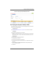
5-5 Managing System Files .................................................................... 5-6
Copying Files via FTP/TFTP or HTTP .................................................... 5-6
Saving the Running Configuration to a Local File................................... 5-8
Setting The Start-Up File......................................................................... 5-9
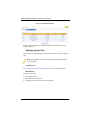
Showing System Files........................................................................... 5-10
x
Table of Contents
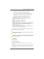
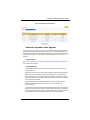
Automatic Operation Code Upgrade..................................................... 5-11
5-6 Setting the System Clock ............................................................... 5-15
Setting the Time Manually..................................................................... 5-15
Setting the SNTP Polling Interval.......................................................... 5-16
Specifying SNTP Time Servers............................................................. 5-17
Setting the Time Zone........................................................................... 5-18
5-7 Configuring the Console Port ........................................................ 5-19
5-8 Configuring Telnet Settings ............................................................ 5-21
5-9 Displaying CPU Utilization ............................................................. 5-22
5-10 Displaying Memory Utilization ..................................................... 5-23
5-11 Resetting the System ................................................................... 5-24
Chapter 6 Interface Configuration .............................................. 6-1
6-1 Port Configuration ............................................................................. 6-1
Configuring by Port List........................................................................... 6-1
Configuring by Port Range...................................................................... 6-4
Displaying Connection Status ................................................................. 6-6
Configuring Local Port Mirroring ............................................................. 6-7
Configuring Remote Port Mirroring ......................................................... 6-9
Showing Port or Trunk Statistics ........................................................... 6-13
Performing Cable Diagnostics .............................................................. 6-18
6-2 Trunk Configuration ........................................................................ 6-19
Configuring a Static Trunk..................................................................... 6-20
Configuring a Dynamic Trunk................................................................ 6-23
Displaying LACP Port Counters............................................................ 6-28
Displaying LACP Settings and Status for the Local Side ...................... 6-29
Displaying LACP Settings and Status for the Remote Side .................. 6-31
Configuring Trunk Mirroring .................................................................. 6-32
6-3 Saving Power ................................................................................... 6-34
6-4 Traffic Segmentation ....................................................................... 6-36
Enabling Traffic Segmentation .............................................................. 6-36
Configuring Uplink and Downlink Ports................................................. 6-37
6-5 VLAN Trunking ................................................................................ 6-38
Chapter 7 VLAN Configuration ..................................................... 7-1
7-1 IEEE 802.1Q VLANs......................................................................... 7-1
Assigning Ports to VLANs ....................................................................... 7-2
VLAN Classification.............................................................................. 7-2
Port Overlapping .................................................................................. 7-3
xi
SSE-G2252/SSE-G2252P Switches USER’S MANUAL
Untagged VLANs ................................................................................. 7-3
Automatic VLAN Registration............................................................... 7-3
Forwarding Tagged/Untagged Frames ................................................... 7-4
Configuring VLAN Groups ...................................................................... 7-4
Adding Static Members to VLANs ........................................................... 7-6
Configuring Dynamic VLAN Registration .............................................. 7-10
7-2 IEEE 802.1Q Tunneling.................................................................. 7-13
Enabling QinQ Tunneling on the Switch ............................................... 7-17
Adding an Interface to a QinQ Tunnel................................................... 7-18
7-3 Protocol VLANs ............................................................................... 7-19
Configuring Protocol VLAN Groups ...................................................... 7-20
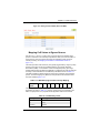
Mapping Protocol Groups to Interfaces ................................................ 7-21
7-4 Configuring IP Subnet VLANs ....................................................... 7-23
7-5 Configuring MAC-based VLANs ................................................... 7-25
7-6 Configuring VLAN Mirroring........................................................... 7-27
Chapter 8 Address Table Settings ............................................. 8-1
8-1 Setting Static Addresses .................................................................. 8-1
8-2 Changing the Aging Time ................................................................ 8-3
8-3 Displaying the Dynamic Address Table ......................................... 8-4
8-4 Clearing the Dynamic Address Table ............................................. 8-5
8-5 Configuring MAC Address Mirroring .............................................. 8-6
Chapter 9 Spanning Tree Algorithm ......................................... 9-1
9-1 Overview ............................................................................................. 9-1
STP ......................................................................................................... 9-2
RSTP ...................................................................................................... 9-2
MSTP ...................................................................................................... 9-2
9-2 Configuring Loopback Detection..................................................... 9-4
9-3 Configuring Global Settings for STA .............................................. 9-5
Displaying Global Settings for STA ....................................................... 9-11
9-4 Configuring Interface Settings for STA ........................................ 9-12
9-5 Displaying Interface Settings for STA .......................................... 9-16
9-6 Configuring Multiple Spanning Trees ........................................... 9-19
9-7 Configuring Interface Settings for MSTP ..................................... 9-22
Chapter 10 Congestion Control ................................................. 10-1
10-1 Rate Limiting .................................................................................. 10-1
xii
Table of Contents
10-2 Storm Control ................................................................................. 10-4
10-3 Automatic Traffic Control ............................................................. 10-6
Setting the ATC Timers ......................................................................... 10-7
Configuring ATC Thresholds and Responses ....................................... 10-9
Chapter 11 Class of Service ......................................................... 11-1
11-1 Layer 2 Queue Settings ............................................................... 11-1
Setting the Default Priority for Interfaces .............................................. 11-1
Selecting the Queue Mode ................................................................... 11-2
Mapping CoS Values to Egress Queues............................................... 11-5
11-2 Layer 3/4 Priority Settings ............................................................ 11-7
Mapping Layer 3/4 Priorities to CoS Values ......................................... 11-7
Setting Priority Processing to DSCP or CoS ........................................ 11-8
Mapping Ingress DSCP Values to Internal DSCP Values ..................... 11-9
Mapping CoS Priorities to Internal DSCP Values................................ 11-11
Chapter 12 Quality of Service ..................................................... 12-1
12-1 Overview......................................................................................... 12-1
12-2 Configuring a Class Map ............................................................. 12-2
12-3 Creating QoS Policies .................................................................. 12-5
12-4 Attaching a Policy Map to a Port .............................................. 12-14
Chapter 13 VoIP Traffic Configuration .................................. 13-1
13-1 Overview......................................................................................... 13-1
13-2 Configuring VoIP Traffic ............................................................... 13-1
13-3 Configuring Telephony OUI ......................................................... 13-3
13-4 Configuring VoIP Traffic Ports ..................................................... 13-4
Chapter 14 Security Measures.................................................... 14-1
14-1 AAA Authorization and Accounting ............................................ 14-2
Configuring Local/Remote Logon Authentication.................................. 14-3
Configuring Remote Logon Authentication Servers.............................. 14-4
Configuring AAA Accounting................................................................. 14-9
Configuring AAA Authorization ........................................................... 14-14
14-2 Configuring User Accounts ........................................................ 14-17
14-3 Web Authentication..................................................................... 14-19
Configuring Global Settings for Web Authentication ........................... 14-19
Configuring Interface Settings for Web Authentication ....................... 14-21
14-4 Network Access (MAC Address Authentication) .................... 14-22
xiii
SSE-G2252/SSE-G2252P Switches USER’S MANUAL
Configuring Global Settings for Network Access ................................ 14-24
Configuring Network Access for Ports ................................................ 14-25
Configuring Port Link Detection .......................................................... 14-27
Configuring a MAC Address Filter ...................................................... 14-28
Displaying Secure MAC Address Information..................................... 14-30
14-5 Configuring HTTPS..................................................................... 14-31
Configuring Global Settings for HTTPS .............................................. 14-31
Replacing the Default Secure-site Certificate ..................................... 14-33
14-6 Configuring the Secure Shell ................................................... 14-34
Configuring the SSH Server................................................................ 14-37
Generating the Host Key Pair ............................................................. 14-38
Importing User Public Keys................................................................. 14-40
14-7 Access Control Lists ................................................................... 14-42
Showing TCAM Utilization .................................................................. 14-43
Setting the ACL Name and Type ........................................................ 14-44
Configuring a Standard IPv4 ACL ....................................................... 14-45
Configuring an Extended IPv4 ACL .................................................... 14-47
Configuring a Standard IPv6 ACL ....................................................... 14-50
Configuring an Extended IPv6 ACL .................................................... 14-52
Configuring a MAC ACL...................................................................... 14-54
Configuring an ARP ACL .................................................................... 14-56
Binding a Port to an Access Control List............................................. 14-58
14-8 ARP Inspection ............................................................................ 14-59
Configuring Global Settings for ARP Inspection ................................. 14-60
Configuring VLAN Settings for ARP Inspection .................................. 14-62
Configuring Interface Settings for ARP Inspection.............................. 14-63
Displaying ARP Inspection Statistics .................................................. 14-65
Displaying the ARP Inspection Log..................................................... 14-66
14-9 Filtering IP Addresses for Management Access .................... 14-67
14-10 Configuring Port Security......................................................... 14-69
14-11 Configuring 802.1X Port Authentication ............................... 14-72
Configuring 802.1X Global Settings.................................................... 14-74
Configuring Port Authenticator Settings for 802.1X ............................ 14-75
Configuring Port Supplicant Settings for 802.1X................................. 14-79
Displaying 802.1X Statistics................................................................ 14-81
14-12 IP Source Guard ....................................................................... 14-84
Configuring Ports for IP Source Guard ............................................... 14-84
Configuring Static Bindings for IP Source Guard ................................ 14-86
xiv
Table of Contents
Displaying Information for Dynamic IP Source Guard Bindings.......... 14-88
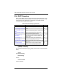
14-13 DHCP Snooping ........................................................................ 14-89
DHCP Snooping Configuration ........................................................... 14-91
DHCP Snooping VLAN Configuration................................................. 14-92
Displaying DHCP Snooping Binding Information ................................ 14-95
Chapter 15 Basic Administration Protocols ...................... 15-1
15-1 Configuring Event Logging .......................................................... 15-1
System Log Configuration..................................................................... 15-1
Remote Log Configuration .................................................................... 15-4
Sending Simple Mail Transfer Protocol Alerts....................................... 15-5
15-2 Link Layer Discovery Protocol .................................................... 15-8
Setting LLDP Timing Attributes ............................................................. 15-8
Configuring LLDP Interface Attributes ................................................ 15-10
Configuring LLDP Interface Civic-Address ......................................... 15-14
Displaying LLDP Local Device Information......................................... 15-16
Displaying LLDP Remote Port Information ......................................... 15-19
Displaying Device Statistics ................................................................ 15-23
15-3 Power Over Ethernet .................................................................. 15-25
Displaying the Switch’s Overall PoE Power Budget............................ 15-26
Setting The Port PoE Power Budget................................................... 15-27
15-4 Simple Network Management Protocol .................................. 15-29
Configuring Global Settings for SNMP................................................ 15-32
Setting the Local Engine ID ................................................................ 15-33
Specifying a Remote Engine ID .......................................................... 15-34
Setting SNMPv3 Views ...................................................................... 15-35
Configuring SNMPv3 Groups ............................................................. 15-38
Setting Community Access Strings .................................................... 15-43
Configuring Local SNMPv3 Users ..................................................... 15-44
Configuring Remote SNMPv3 Users ................................................. 15-46
Specifying Notification Managers........................................................ 15-49
15-5 Remote Monitoring ..................................................................... 15-53
Configuring RMON Alarms ................................................................. 15-53
Configuring RMON Events.................................................................. 15-57
Configuring RMON History Samples .................................................. 15-60
Configuring RMON Statistical Samples .............................................. 15-63
15-6 Switch Clustering ........................................................................ 15-66
Configuring General Settings for Clusters .......................................... 15-67
Cluster Member Configuration ............................................................ 15-68
xv
SSE-G2252/SSE-G2252P Switches USER’S MANUAL
15-7 Setting A Time Range ................................................................ 15-71
Chapter 16 IP Configuration......................................................... 16-1
16-1 Using the Ping Function ............................................................... 16-1
16-2 Address Resolution Protocol ...................................................... 16-3
Setting the ARP Timeout....................................................................... 16-3
Displaying ARP Entries......................................................................... 16-4
16-3 Setting the Switch’s IP Address (IP Version 4) ........................ 16-5
16-4 Setting the Switch’s IP Address (IP Version 6) ........................ 16-7
Configuring the IPv6 Default Gateway.................................................. 16-8
Configuring IPv6 Interface Settings ...................................................... 16-9
Configuring an IPv6 Address .............................................................. 16-10
Showing IPv6 Addresses .................................................................... 16-13
Showing the IPv6 Neighbor Cache ..................................................... 16-14
Showing IPv6 Statistics ....................................................................... 16-16
Chapter 17 IP Services .................................................................... 17-1
17-1 Configuring General DNS Service Parameters ....................... 17-1
17-2 Configuring a List of Domain Names ......................................... 17-2
17-3 Configuring a List of Name Servers ........................................... 17-4
17-4 Configuring Static DNS Host to Address Entries ..................... 17-5
17-5 Displaying the DNS Cache .......................................................... 17-6
Chapter 18 Multicast Filtering .................................................... 18-1
18-1 Overview......................................................................................... 18-1
18-2 Layer 2 IGMP (Snooping and Query) ........................................ 18-2
Configuring IGMP Snooping and Query Parameters............................ 18-4
Specifying Static Interfaces for a Multicast Router................................ 18-8
Assigning Interfaces to Multicast Services.......................................... 18-10
Setting IGMP Snooping Status per Interface ...................................... 18-12
Displaying Multicast Groups Discovered by IGMP Snooping ............. 18-17
18-3 Filtering and Throttling IGMP Groups ...................................... 18-18
Enabling IGMP Filtering and Throttling ............................................... 18-18
Configuring IGMP Filter Profiles ......................................................... 18-19
Configuring IGMP Filtering and Throttling for Interfaces..................... 18-22
18-4 Multicast VLAN Registration ..................................................... 18-23
Configuring Global MVR Settings ....................................................... 18-25
Configuring MVR Interface Status....................................................... 18-26
Assigning Static Multicast Groups to Interfaces .................................. 18-28
xvi
Table of Contents
Showing Multicast Group Members .................................................... 18-30
Chapter 19 Using the Command Line Interface ............... 19-1
19-1 Accessing the CLI ......................................................................... 19-1
Console Connection.............................................................................. 19-1
Telnet Connection ................................................................................. 19-2
19-2 Entering Commands ..................................................................... 19-3
Keywords and Arguments ..................................................................... 19-3
Minimum Abbreviation .......................................................................... 19-3
Command Completion .......................................................................... 19-3
Getting Help on Commands.................................................................. 19-3
Showing Commands .......................................................................... 19-4
Partial Keyword Lookup ........................................................................ 19-6
Negating the Effect of Commands ........................................................ 19-6
Using Command History ....................................................................... 19-6
Understanding Command Modes ......................................................... 19-6
Exec Commands................................................................................... 19-7
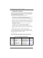
Configuration Commands ..................................................................... 19-8
Command Line Processing................................................................... 19-9
Showing Status Information ................................................................ 19-10
Output Modifiers.................................................................................. 19-11
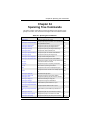
19-3 CLI Command Groups ............................................................... 19-11
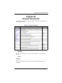
Chapter 20 General Commands................................................. 20-1
prompt................................................................................................... 20-1
reload (Global Configuration)................................................................ 20-2
enable ................................................................................................... 20-3
quit ........................................................................................................ 20-4
show history .......................................................................................... 20-4
configure ............................................................................................... 20-5
disable................................................................................................... 20-6
reload (Privileged Exec)........................................................................ 20-6
show reload........................................................................................... 20-7
end ........................................................................................................ 20-7
exit ........................................................................................................ 20-8
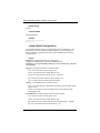
Chapter 21 System Management Commands ................... 21-1
21-1 Device Designation ....................................................................... 21-2
hostname .............................................................................................. 21-2
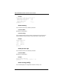
21-2 System Status ................................................................................ 21-3
show access-list tcam-utilization........................................................... 21-3
xvii
SSE-G2252/SSE-G2252P Switches USER’S MANUAL
show memory........................................................................................ 21-4
show process cpu ................................................................................. 21-4
show running-config.............................................................................. 21-4
show startup-config ............................................................................... 21-7
show system ......................................................................................... 21-8
show tech-support................................................................................. 21-9
show users.......................................................................................... 21-10
show version ....................................................................................... 21-11
21-3 Frame Size ................................................................................... 21-12
jumbo frame ........................................................................................ 21-12
21-4 File Management ........................................................................ 21-13
boot system......................................................................................... 21-14
copy .................................................................................................... 21-15
delete .................................................................................................. 21-18
dir ........................................................................................................ 21-18
whichboot............................................................................................ 21-20
upgrade opcode auto .......................................................................... 21-20
upgrade opcode path .......................................................................... 21-22
21-5 Line ................................................................................................ 21-23
line ...................................................................................................... 21-24
databits................................................................................................ 21-25
exec-timeout ....................................................................................... 21-26
login .................................................................................................... 21-27
parity ................................................................................................... 21-28
password............................................................................................. 21-29
password-thresh ................................................................................. 21-30
silent-time............................................................................................ 21-31
speed .................................................................................................. 21-32
stopbits................................................................................................ 21-33
timeout login response........................................................................ 21-34
disconnect........................................................................................... 21-35
show line ............................................................................................. 21-36
21-6 Event Logging .............................................................................. 21-37
logging facility ..................................................................................... 21-37
logging history..................................................................................... 21-38
logging host......................................................................................... 21-39
logging on ........................................................................................... 21-40
logging trap ......................................................................................... 21-41
clear log .............................................................................................. 21-42
xviii
Table of Contents
show log.............................................................................................. 21-43
show logging ....................................................................................... 21-44
21-7 SMTP Alerts ................................................................................. 21-46
logging sendmail ................................................................................. 21-46
logging sendmail host ......................................................................... 21-47
logging sendmail level......................................................................... 21-48
logging Sendmail Destination-Email ................................................... 21-49
logging Sendmail Source-Email.......................................................... 21-50
show logging sendmail........................................................................ 21-50
21-8 Time .............................................................................................. 21-51
sntp client............................................................................................ 21-52
sntp poll............................................................................................... 21-53
sntp server .......................................................................................... 21-54
show sntp............................................................................................ 21-55
clock timezone .................................................................................... 21-56
clock timezone-predefined .................................................................. 21-57
calendar set ........................................................................................ 21-58
Syntax .............................................................................................. 21-58
show calendar..................................................................................... 21-59
21-9 Time Range.................................................................................. 21-59
time-range........................................................................................... 21-60
absolute .............................................................................................. 21-61
periodic ............................................................................................... 21-62
show time-range ................................................................................. 21-63
21-10 Switch Clustering ...................................................................... 21-64
cluster ................................................................................................. 21-65
cluster commander ............................................................................. 21-66
cluster ip-pool...................................................................................... 21-66
cluster member ................................................................................... 21-67
rcommand ........................................................................................... 21-68
show cluster ........................................................................................ 21-69
show cluster members ........................................................................ 21-69
show cluster candidates...................................................................... 21-70
Chapter 22 SNMP Commands..................................................... 22-1
snmp-server .......................................................................................... 22-2
snmp-server community........................................................................ 22-3
snmp-server contact ............................................................................. 22-4
snmp-server location............................................................................. 22-5
show snmp............................................................................................ 22-6
xix
SSE-G2252/SSE-G2252P Switches USER’S MANUAL
snmp-server enable traps ..................................................................... 22-7
snmp-server host ................................................................................. 22-8
snmp-server engine-id ........................................................................ 22-10
snmp-server group.............................................................................. 22-12
snmp-server user ................................................................................ 22-13
snmp-server view................................................................................ 22-15
show snmp engine-id .......................................................................... 22-16
show snmp group................................................................................ 22-16
show snmp user.................................................................................. 22-17
show snmp view.................................................................................. 22-18
nlm ...................................................................................................... 22-19
snmp-server notify-filter ...................................................................... 22-19
show nlm oper-status .......................................................................... 22-21
show snmp notify-filter ........................................................................ 22-22
Chapter 23 Remote Monitoring Commands ....................... 23-1
rmon alarm............................................................................................ 23-2
rmon event ........................................................................................... 23-3
rmon collection history .......................................................................... 23-4
rmon collection rmon1 .......................................................................... 23-5
show rmon alarms................................................................................. 23-6
show rmon events ................................................................................. 23-6
show rmon history................................................................................. 23-6
show rmon statistics.............................................................................. 23-8
Chapter 24 Authentication Commands ................................ 24-1
24-1 User Accounts ............................................................................... 24-2
enable password................................................................................... 24-2
username .............................................................................................. 24-3
24-2 Authentication Sequence ............................................................. 24-4
authentication enable............................................................................ 24-4
authentication login ............................................................................... 24-6
24-3 RADIUS Client ............................................................................... 24-7
radius-server acct-port .......................................................................... 24-7
radius-server auth-port.......................................................................... 24-8
radius-server host ................................................................................. 24-9
radius-server key ................................................................................ 24-10
radius-server retransmit ...................................................................... 24-10
radius-server timeout .......................................................................... 24-11
show radius-server.............................................................................. 24-12
xx
Table of Contents
24-4 TACACS+ Client.......................................................................... 24-13
tacacs-server host............................................................................... 24-13
tacacs-server key ................................................................................ 24-14
tacacs-server port ............................................................................... 24-15
show tacacs-server ............................................................................. 24-15
24-5 AAA ............................................................................................... 24-16
aaa accounting commands ................................................................. 24-17
aaa accounting dot1x.......................................................................... 24-18
aaa accounting exec ........................................................................... 24-19
aaa accounting update........................................................................ 24-20
aaa authorization exec........................................................................ 24-21
aaa group server................................................................................. 24-22
server .................................................................................................. 24-22
accounting dot1x................................................................................. 24-23
accounting exec .................................................................................. 24-24
authorization exec............................................................................... 24-25
show accounting ................................................................................. 24-26
24-6 Web Server .................................................................................. 24-27
ip http port ........................................................................................... 24-27
ip http server ....................................................................................... 24-28
ip http secure-server ........................................................................... 24-28
ip http secure-port ............................................................................... 24-30
24-7 Telnet Server ................................................................................ 24-31
ip telnet max-sessions ........................................................................ 24-31
ip telnet port ........................................................................................ 24-32
ip telnet server .................................................................................... 24-33
show ip telnet ...................................................................................... 24-33
24-8 Secure Shell................................................................................. 24-34
ip ssh authentication-retries ................................................................ 24-37
ip ssh server........................................................................................ 24-38
ip ssh server-key size ......................................................................... 24-39
ip ssh timeout...................................................................................... 24-40
delete public-key ................................................................................. 24-40
ip ssh crypto host-key generate .......................................................... 24-41
ip ssh crypto zeroize ........................................................................... 24-42
ip ssh save host-key ........................................................................... 24-43
show ip ssh ......................................................................................... 24-43
show public-key .................................................................................. 24-44
show ssh ............................................................................................. 24-44
xxi
SSE-G2252/SSE-G2252P Switches USER’S MANUAL
24-9 802.1X Port Authentication ........................................................ 24-46
dot1x default ....................................................................................... 24-47
dot1x eapol-pass-through ................................................................... 24-47
dot1x system-auth-control................................................................... 24-48
dot1x intrusion-action.......................................................................... 24-48
dot1x max-req ..................................................................................... 24-49
dot1x operation-mode ......................................................................... 24-50
dot1x port-control ................................................................................ 24-51
dot1x re-authentication ....................................................................... 24-52
dot1x timeout quiet-period .................................................................. 24-53
dot1x timeout re-authperiod ................................................................ 24-54
dot1x timeout supp-timeout................................................................. 24-55
dot1x timeout tx-period ....................................................................... 24-56
dot1x re-authenticate .......................................................................... 24-57
dot1x identity profile ............................................................................ 24-58
dot1x max-start ................................................................................... 24-59
dot1x pae supplicant ........................................................................... 24-60
dot1x timeout auth-period ................................................................... 24-61
dot1x timeout held-period ................................................................... 24-62
dot1x timeout start-period ................................................................... 24-63
show dot1x.......................................................................................... 24-64
24-10 Management IP Filter ............................................................... 24-67
management ....................................................................................... 24-67
show management.............................................................................. 24-69
Chapter 25 General Security Measures ................................ 25-1
25-1 Port Security .................................................................................. 25-2
port security .......................................................................................... 25-2
25-2 Network Access (MAC Address Authentication) ...................... 25-4
network-access aging ........................................................................... 25-5
network-access mac-filter ..................................................................... 25-6
mac-authentication reauth-time ............................................................ 25-7
network-access dynamic-qos................................................................ 25-8
network-access dynamic-vlan............................................................... 25-9
network-access guest-vlan ................................................................. 25-10
network-access link-detection............................................................. 25-10
network-access link-detection link-down............................................. 25-11
network-access link-detection link-up ................................................. 25-12
network-access link-detection link-up-down ....................................... 25-12
network-access max-mac-count ......................................................... 25-13
xxii
Table of Contents
network-access mode mac-authentication.......................................... 25-14
network-access port-mac-filter............................................................ 25-15
mac-authentication intrusion-action .................................................... 25-15
mac-authentication max-mac-count.................................................... 25-16
clear network-access .......................................................................... 25-17
show network-access.......................................................................... 25-18
show network-access mac-address-table ........................................... 25-19
show network-access mac-filter.......................................................... 25-20
25-3 Web Authentication..................................................................... 25-20
web-auth login-attempts...................................................................... 25-21
web-auth quiet-period ......................................................................... 25-22
web-auth session-timeout ................................................................... 25-22
web-auth system-auth-control............................................................. 25-23
web-auth ............................................................................................. 25-24
web-auth re-authenticate (Port) .......................................................... 25-24
web-auth re-authenticate (IP) ............................................................. 25-25
show web-auth.................................................................................... 25-26
show web-auth interface ..................................................................... 25-26
show web-auth summary .................................................................... 25-27
25-4 DHCP Snooping .......................................................................... 25-28
ip dhcp snooping................................................................................. 25-28
ip dhcp snooping database flash ........................................................ 25-30
ip dhcp snooping information option ................................................... 25-31
ip dhcp snooping information policy.................................................... 25-32
ip dhcp snooping verify mac-address ................................................. 25-33
ip dhcp snooping vlan ......................................................................... 25-34
ip dhcp snooping trust......................................................................... 25-35
clear ip dhcp snooping database flash................................................ 25-36
show ip dhcp snooping ....................................................................... 25-36
show ip dhcp snooping binding........................................................... 25-37
25-5 IP Source Guard ......................................................................... 25-37
ip source-guard binding ...................................................................... 25-38
ip source-guard ................................................................................... 25-39
ip source-guard max-binding .............................................................. 25-41
show ip source-guard.......................................................................... 25-42
show ip source-guard binding ............................................................. 25-42
25-6 ARP Inspection ............................................................................ 25-43
ip arp inspection.................................................................................. 25-44
ip arp inspection filter .......................................................................... 25-45
xxiii
SSE-G2252/SSE-G2252P Switches USER’S MANUAL
ip arp inspection log-buffer logs .......................................................... 25-46
ip arp inspection validate .................................................................... 25-47
ip arp inspection vlan .......................................................................... 25-48
ip arp inspection limit .......................................................................... 25-49
ip arp inspection trust.......................................................................... 25-50
show ip arp inspection configuration................................................... 25-50
show ip arp inspection interface.......................................................... 25-51
show ip arp inspection log................................................................... 25-51
show ip arp inspection statistics.......................................................... 25-51
show ip arp inspection vlan................................................................. 25-53
Chapter 26 Access Control Lists .............................................. 26-1
26-1 IPv4 ACLs ...................................................................................... 26-1
access-list ip ......................................................................................... 26-2
permit, deny, redirect-to (Standard IP ACL) ......................................... 26-3
permit, deny, redirect-to (Extended IPv4 ACL) ..................................... 26-4
ip access-group .................................................................................... 26-8
show ip access-group ........................................................................... 26-8
show ip access-list ................................................................................ 26-9
26-2 IPv6 ACLs .................................................................................... 26-10
access-list ipv6.................................................................................... 26-11
permit, deny, redirect-to (Standard IPv6 ACL) ................................... 26-12
permit, deny, redirect-to (Extended IPv6 ACL) ................................... 26-13
show ipv6 access-list .......................................................................... 26-15
ipv6 access-group............................................................................... 26-16
show ipv6 access-group ..................................................................... 26-17
26-3 MAC ACLs ................................................................................... 26-17
access-list mac ................................................................................... 26-18
permit, deny, redirect-to (MAC ACL) ................................................... 26-19
mac access-group............................................................................... 26-22
show mac access-group ..................................................................... 26-23
show mac access-list .......................................................................... 26-23
26-4 ARP ACLs .................................................................................... 26-23
access-list arp ..................................................................................... 26-24
permit, deny (ARP ACL) ..................................................................... 26-25
show arp access-list............................................................................ 26-26
26-5 ACL Information .......................................................................... 26-27
show access-group ............................................................................. 26-27
show access-list.................................................................................. 26-28
xxiv
Table of Contents
Chapter 27 Interface Commands .............................................. 27-1
interface ................................................................................................ 27-2
alias....................................................................................................... 27-3
capabilities ............................................................................................ 27-4
description............................................................................................. 27-5
flowcontrol............................................................................................. 27-6
giga-phy-mode ...................................................................................... 27-7
media-type ............................................................................................ 27-8
negotiation ............................................................................................ 27-9
shutdown............................................................................................. 27-10
speed-duplex ...................................................................................... 27-10
switchport packet-rate......................................................................... 27-12
clear counters ..................................................................................... 27-13
show interfaces counters .................................................................... 27-14
show interfaces status ........................................................................ 27-15
show interfaces switchport.................................................................. 27-16
show interfaces transceiver ................................................................ 27-19
test cable-diagnostics ......................................................................... 27-20
show cable-diagnostics....................................................................... 27-22
power-save ........................................................................................ 27-22
show power-save ................................................................................ 27-24
Chapter 28 Link Aggregation Commands ........................... 28-1
channel-group ...................................................................................... 28-2
lacp ....................................................................................................... 28-3
lacp admin-key (Ethernet Interface)...................................................... 28-5
lacp port-priority .................................................................................... 28-6
lacp system-priority ............................................................................... 28-7
lacp admin-key (Port Channel) ............................................................. 28-8
show lacp .............................................................................................. 28-9
Chapter 29 Power Over Ethernet Commands ................... 29-1
power inline compatible ........................................................................ 29-1
power inline........................................................................................... 29-3
power inline maximum allocation .......................................................... 29-4
power inline priority ............................................................................... 29-4
power inline time-range......................................................................... 29-6
show power inline status ....................................................................... 29-6
show power inline time-range ............................................................... 29-8
show power poe.................................................................................... 29-9
xxv
SSE-G2252/SSE-G2252P Switches USER’S MANUAL
Chapter 30 Port Mirroring Commands .................................. 30-1
30-1 Local Port Mirroring Commands ................................................. 30-1
port monitor........................................................................................... 30-2
show port monitor ................................................................................. 30-4
30-2 RSPAN Mirroring Commands ..................................................... 30-5
rspan source ......................................................................................... 30-6
rspan destination................................................................................... 30-7
rspan remote vlan ................................................................................. 30-8
no rspan session................................................................................. 30-10
show rspan.......................................................................................... 30-11
Chapter 31 Rate Limit Commands ........................................... 31-1
rate-limit ................................................................................................ 31-1
Chapter 32 Automatic Traffic Control Commands ......... 32-1
auto-traffic-control apply-timer ............................................................. 32-2
auto-traffic-control release-timer ........................................................... 32-3
auto-traffic-control ................................................................................. 32-3
auto-traffic-control action ...................................................................... 32-4
auto-traffic-control alarm-clear-threshold .............................................. 32-6
auto-traffic-control alarm-fire-threshold ................................................. 32-7
auto-traffic-control auto-control-release ................................................ 32-8
auto-traffic-control control-release ........................................................ 32-9
snmp-server enable port-traps atc broadcast-alarm-clear .................. 32-10
snmp-server enable port-traps atc broadcast-alarm-fire ..................... 32-11
snmp-server enable port-traps atc broadcast-control-apply ............... 32-12
snmp-server enable port-traps atc broadcast-control-release ............ 32-13
snmp-server enable port-traps atc multicast-alarm-clear.................... 32-14
snmp-server enable port-traps atc multicast-alarm-fire....................... 32-15
snmp-server enable port-traps atc multicast-control-apply ................. 32-16
snmp-server enable port-traps atc multicast-control-release .............. 32-17
show auto-traffic-control...................................................................... 32-18
show auto-traffic-control interface ....................................................... 32-18
Chapter 33 Address Table Commands ................................. 33-1
mac-address-table aging-time .............................................................. 33-2
mac-address-table static ....................................................................... 33-2
clear mac-address-table dynamic ......................................................... 33-4
show mac-address-table ....................................................................... 33-4
show mac-address-table aging-time ..................................................... 33-5
show mac-address-table count ............................................................. 33-6
xxvi
Table of Contents
Chapter 34 Spanning Tree Commands ................................. 34-1
spanning-tree ........................................................................................ 34-2
spanning-tree cisco-prestandard........................................................... 34-3
spanning-tree forward-time ................................................................... 34-3
spanning-tree hello-time ....................................................................... 34-4
spanning-tree max-age ......................................................................... 34-5
spanning-tree mode .............................................................................. 34-6
spanning-tree pathcost method............................................................. 34-7
spanning-tree priority ............................................................................ 34-8
spanning-tree mst configuration............................................................ 34-9
spanning-tree transmission-limit ......................................................... 34-10
max-hops ............................................................................................ 34-11
mst priority .......................................................................................... 34-12
mst vlan............................................................................................... 34-13
name ................................................................................................... 34-14
revision................................................................................................ 34-15
spanning-tree bpdu-filter ..................................................................... 34-16
spanning-tree bpdu-guard................................................................... 34-17
spanning-tree cost .............................................................................. 34-18
spanning-tree edge-port...................................................................... 34-19
spanning-tree link-type........................................................................ 34-20
spanning-tree loopback-detection ....................................................... 34-20
spanning-tree loopback-detection release-mode ................................ 34-22
spanning-tree loopback-detection trap................................................ 34-23
spanning-tree mst cost........................................................................ 34-23
spanning-tree mst port-priority ............................................................ 34-25
spanning-tree port-priority ................................................................... 34-26
spanning-tree root-guard .................................................................... 34-27
spanning-tree spanning-disabled ........................................................ 34-28
spanning-tree loopback-detection release .......................................... 34-28
spanning-tree protocol-migration ........................................................ 34-29
show spanning-tree............................................................................. 34-30
show spanning-tree mst configuration ................................................ 34-32
Chapter 35 VLAN Commands ..................................................... 35-1
35-1 GVRP and Bridge Extension Commands ................................. 35-2
bridge-ext gvrp ...................................................................................... 35-2
garp timer.............................................................................................. 35-3
switchport forbidden vlan ...................................................................... 35-4
switchport gvrp...................................................................................... 35-5
xxvii
SSE-G2252/SSE-G2252P Switches USER’S MANUAL
show bridge-ext..................................................................................... 35-6
show garp timer .................................................................................... 35-6
show gvrp configuration ........................................................................ 35-7
35-2 Editing VLAN Groups ................................................................... 35-8
vlan database........................................................................................ 35-8
vlan ....................................................................................................... 35-9
35-3 Configuring VLAN Interfaces..................................................... 35-10
interface vlan....................................................................................... 35-11
switchport acceptable-frame-types .................................................... 35-12
switchport allowed vlan ....................................................................... 35-13
switchport ingress-filtering ................................................................. 35-14
switchport mode.................................................................................. 35-14
switchport native vlan.......................................................................... 35-16
vlan-trunking ....................................................................................... 35-17
35-4 Displaying VLAN Information .................................................... 35-18
show vlan ............................................................................................ 35-18
35-5 Configuring IEEE 802.1Q Tunneling ........................................ 35-20
dot1q-tunnel system-tunnel-control..................................................... 35-21
switchport dot1q-tunnel mode............................................................. 35-22
switchport dot1q-tunnel tpid ................................................................ 35-23
show dot1q-tunnel............................................................................... 35-24
35-6 Configuring Port-based Traffic Segmentation ........................ 35-24
traffic-segmentation ............................................................................ 35-24
show traffic-segmentation ................................................................... 35-25
35-7 Configuring Protocol-based VLANs ......................................... 35-26
protocol-vlan protocol-group (Configuring Groups)............................. 35-27
protocol-vlan protocol-group (Configuring Interfaces)......................... 35-28
show protocol-vlan protocol-group...................................................... 35-29
show interfaces protocol-vlan protocol-group ..................................... 35-30
35-8 Configuring IP Subnet VLANs................................................... 35-31
subnet-vlan ......................................................................................... 35-31
show subnet-vlan ................................................................................ 35-32
35-9 Configuring MAC Based VLANs ............................................... 35-33
mac-vlan ............................................................................................. 35-33
show mac-vlan .................................................................................... 35-34
35-10 Configuring Voice VLANs ........................................................ 35-35
voice vlan ............................................................................................ 35-36
voice vlan aging .................................................................................. 35-37
xxviii
Table of Contents
voice vlan mac-address ...................................................................... 35-38
switchport voice vlan .......................................................................... 35-39
switchport voice vlan priority ............................................................... 35-40
switchport voice vlan rule.................................................................... 35-41
switchport voice vlan security ............................................................. 35-42
show voice vlan................................................................................... 35-43
Chapter 36 Class of Service Commands ............................. 36-1
36-1 Priority Commands (Layer 2) ...................................................... 36-1
queue mode .......................................................................................... 36-2
queue weight......................................................................................... 36-4
switchport priority default ...................................................................... 36-5
show queue mode................................................................................. 36-6
show queue weight ............................................................................... 36-6
36-2 Priority Commands (Layer 3 and 4) ........................................... 36-7
qos map cos-dscp................................................................................. 36-7
qos map dscp-mutation......................................................................... 36-9
qos map phb-queue ............................................................................ 36-10
qos map trust-mode ............................................................................ 36-12
show qos map dscp-mutation ............................................................. 36-13
show qos map phb-queue................................................................... 36-14
show qos map cos-dscp ..................................................................... 36-15
show qos map trust-mode................................................................... 36-16
Chapter 37 Quality of Service Commands .......................... 37-1
class-map.............................................................................................. 37-2
description ............................................................................................ 37-3
match .................................................................................................... 37-4
rename.................................................................................................. 37-5
policy-map............................................................................................. 37-6
class...................................................................................................... 37-7
police flow ............................................................................................. 37-8
police srtcm-color.................................................................................. 37-9
police trtcm-color................................................................................. 37-12
set cos................................................................................................. 37-14
set ip dscp........................................................................................... 37-15
set phb ................................................................................................ 37-16
service-policy ...................................................................................... 37-17
show class-map .................................................................................. 37-18
show policy-map ................................................................................. 37-19
show policy-map interface .................................................................. 37-20
xxix
SSE-G2252/SSE-G2252P Switches USER’S MANUAL
Chapter 38 Multicast Filtering Commands ......................... 38-1
38-1 IGMP Snooping ............................................................................. 38-1
ip igmp snooping................................................................................... 38-3
ip igmp snooping proxy-reporting.......................................................... 38-4
ip igmp snooping querier....................................................................... 38-5
ip igmp snooping router-alert-option-check........................................... 38-6
ip igmp snooping router-port-expire-time .............................................. 38-7
ip igmp snooping tcn-flood .................................................................... 38-7
ip igmp snooping tcn-query-solicit ........................................................ 38-9
ip igmp snooping unregistered-data-flood........................................... 38-10
ip igmp snooping unsolicited-report-interval ....................................... 38-11
ip igmp snooping version .................................................................... 38-12
ip igmp snooping version-exclusive .................................................... 38-13
ip igmp snooping vlan general-query-suppression ............................. 38-14
ip igmp snooping vlan immediate-leave.............................................. 38-15
ip igmp snooping vlan last-memb-query-count ................................... 38-16
ip igmp snooping vlan last-memb-query-intvl...................................... 38-17
ip igmp snooping vlan mrd .................................................................. 38-18
ip igmp snooping vlan proxy-address ................................................. 38-19
ip igmp snooping vlan proxy-query-interval ....................................... 38-20
ip igmp snooping vlan proxy-query-resp-intvl ..................................... 38-21
ip igmp snooping vlan static ................................................................ 38-22
show ip igmp snooping ....................................................................... 38-23
show ip igmp snooping group ............................................................ 38-24
38-2 Static Multicast Routing .............................................................. 38-25
ip igmp snooping vlan mrouter............................................................ 38-25
show ip igmp snooping mrouter .......................................................... 38-26
38-3 IGMP Filtering and Throttling .................................................... 38-27
ip igmp filter (Global Configuration) .................................................... 38-28
ip igmp profile...................................................................................... 38-28
permit, deny ........................................................................................ 38-29
range................................................................................................... 38-30
ip igmp filter (Interface Configuration)................................................. 38-30
ip igmp max-groups ............................................................................ 38-31
ip igmp max-groups action .................................................................. 38-32
show ip igmp filter ............................................................................... 38-32
show ip igmp profile ............................................................................ 38-33
show ip igmp throttle interface ............................................................ 38-34
38-4 Multicast VLAN Registration ..................................................... 38-35
xxx
Table of Contents
mvr ...................................................................................................... 38-35
mvr immediate-leave........................................................................... 38-37
mvr type .............................................................................................. 38-38
mvr vlan group .................................................................................... 38-39
show mvr............................................................................................. 38-40
Chapter 39 LLDP Commands ...................................................... 39-1
lldp ........................................................................................................ 39-3
lldp holdtime-multiplier .......................................................................... 39-3
lldp med-fast-start-count ....................................................................... 39-4
lldp notification-interval ......................................................................... 39-4
lldp refresh-interval ............................................................................... 39-5
lldp reinit-delay ...................................................................................... 39-6
lldp tx-delay ........................................................................................... 39-6
lldp admin-status ................................................................................... 39-7
lldp basic-tlv management-ip-address .................................................. 39-8
lldp basic-tlv port-description ................................................................ 39-8
lldp basic-tlv system-capabilities ........................................................... 39-9
lldp basic-tlv system-description ......................................................... 39-10
lldp basic-tlv system-name.................................................................. 39-10
lldp dot1-tlv proto-ident ....................................................................... 39-11
lldp dot1-tlv proto-vid........................................................................... 39-12
lldp dot1-tlv pvid .................................................................................. 39-12
lldp dot1-tlv vlan-name ........................................................................ 39-13
lldp dot3-tlv link-agg ............................................................................ 39-13
lldp dot3-tlv mac-phy........................................................................... 39-14
lldp dot3-tlv max-frame ....................................................................... 39-14
lldp dot3-tlv poe................................................................................... 39-15
lldp med-location civic-addr ................................................................ 39-16
lldp med-notification ............................................................................ 39-18
lldp med-tlv ext-poe............................................................................. 39-18
lldp med-tlv inventory .......................................................................... 39-19
lldp med-tlv location ............................................................................ 39-20
lldp med-tlv med-cap........................................................................... 39-20
lldp med-tlv network-policy.................................................................. 39-21
lldp notification .................................................................................... 39-21
show lldp config .................................................................................. 39-22
show lldp info local-device .................................................................. 39-24
show lldp info remote-device .............................................................. 39-25
show lldp info statistics........................................................................ 39-26
xxxi
SSE-G2252/SSE-G2252P Switches USER’S MANUAL
Chapter 40 Domain Name Service Commands ................ 40-1
ip domain-list......................................................................................... 40-2
ip domain-lookup................................................................................... 40-3
ip domain-name .................................................................................... 40-4
ip host ................................................................................................... 40-5
ip name-server ...................................................................................... 40-6
ipv6 host................................................................................................ 40-7
clear dns cache..................................................................................... 40-7
clear host .............................................................................................. 40-8
show dns............................................................................................... 40-8
show dns cache .................................................................................... 40-9
show hosts .......................................................................................... 40-10
Chapter 41 DHCP Commands ..................................................... 41-1
41-1 DHCP Client................................................................................... 41-1
ip dhcp client class-id............................................................................ 41-2
ip dhcp restart client .............................................................................. 41-3
ipv6 dhcp restart client vlan .................................................................. 41-4
show ip dhcp client-identifier................................................................. 41-5
show ipv6 dhcp duid ............................................................................. 41-5
show ipv6 dhcp vlan.............................................................................. 41-5
Chapter 42 IP Interface Commands......................................... 42-1
42-1 IPv4 Interface................................................................................. 42-1
Basic IPv4 Configuration....................................................................... 42-2
ip address ............................................................................................. 42-2
ip default-gateway................................................................................. 42-4
show ip default-gateway ....................................................................... 42-5
show ip interface ................................................................................... 42-5
traceroute.............................................................................................. 42-6
ping ....................................................................................................... 42-7
ARP Configuration ................................................................................ 42-8
arp timeout ............................................................................................ 42-8
clear arp-cache ..................................................................................... 42-9
show arp ............................................................................................. 42-10
42-2 IPv6 Interface............................................................................... 42-11
ipv6 default-gateway ........................................................................... 42-12
ipv6 address........................................................................................ 42-13
ipv6 address autoconfig ...................................................................... 42-14
ipv6 address eui-64............................................................................. 42-16
xxxii
Table of Contents
ipv6 address link-local......................................................................... 42-18
ipv6 enable.......................................................................................... 42-19
show ipv6 default-gateway.................................................................. 42-20
show ipv6 interface ............................................................................. 42-21
show ipv6 traffic .................................................................................. 42-23
clear ipv6 traffic ................................................................................... 42-28
ping6 ................................................................................................... 42-28
clear ipv6 neighbors............................................................................ 42-29
show ipv6 neighbors ........................................................................... 42-30
Appendix A Software Specifications ........................................A-1
A-1 Software Features ............................................................................A-1
A-2 Management Features .....................................................................A-2
A-3 Standards ...........................................................................................A-3
A-4 Management Information Bases ....................................................A-4
Appendix B Troubleshooting ........................................................B-1
B-1 Problems Accessing the Management Interface .........................B-1
B-2 Using System Logs...........................................................................B-2
Appendix C License Information ............................................... C-1
C-1 The GNU General Public License ................................................. C-1
xxxiii
SSE-G2252/SSE-G2252P Switches USER’S MANUAL
Notes
xxxiv
Chapter 1: Introduction
Chapter 1
Introduction
This section provides an overview of the switch, and introduces some basic concepts
about network switches. It also describes the basic settings required to access the
management interface.
These switches provide a broad range of features for Layer 2 switching. It includes a
management agent that allows you to configure the features listed in this manual. The
default configuration can be used for most of the features provided by this switch.
However, there are many options that you should configure to maximize the switch’s
performance for your particular network environment.
1-1 Key Features
Table 1-1. Key Features
Feature
Description
Configuration Backup
Using management station or FTP/TFTP server
and Restore
Authentication
Console, Telnet, web – user name/password, RADIUS, TACACS+
Web – HTTPS
Telnet – SSH
SNMP v1/2c - Community strings
SNMP version 3 – MD5 or SHA password
Port – IEEE 802.1X, MAC address filtering
General Security
Measures
Private VLANs
Port Authentication
Port Security
DHCP Snooping
IP Source Guard
Access Control Lists
Supports up to 512 rules, 64 ACLs,
and a maximum of 32 rules for an ACL
DHCP
Client
DNS
Client and Proxy service
Port Configuration
Speed and duplex mode and flow control
Port Trunking
Supports up to 12 trunks – static or dynamic trunking (LACP)
Port Mirroring
50 sessions, one or more source ports to one analysis port
Congestion Control
Rate Limiting
Throttling for broadcast, multicast, unknown unicast storms
Random Early Detection
Address Table
16K MAC addresses in the forwarding table, 1K static MAC addresses, 256 L2
multicast groups
1-1
SSE-G2252/SSE-G2252P Switches User’s Manual
Table 1-1. Key Features (Continued)
Feature
Description
IP Version 4
Supports IPv4 addressing, and management
IEEE 802.1D Bridge
Supports dynamic data switching and addresses learning
Store-and-Forward
Switching
Supported to ensure wire-speed switching while eliminating bad frames
Spanning Tree
Algorithm
Supports standard STP, Rapid Spanning Tree Protocol (RSTP), and Multiple
Spanning Trees (MSTP)
Virtual LANs
Up to 256 using IEEE 802.1Q, port-based, protocol-based, private VLANs,
voice VLANs, and QinQ tunnel
Traffic Prioritization
Default port priority, traffic class map, queue scheduling, Differentiated Services
Code Point (DSCP
Qualify of Service
Supports Differentiated Services (DiffServ)
Link Layer Discovery
Protocol
Used to discover basic information about neighboring devices
Multicast Filtering
Supports IGMP snooping and query and Multicast VLAN Registration
1-2 Description of Software Features
The switch provides a wide range of advanced performance enhancing features. Flow
control eliminates the loss of packets due to bottlenecks caused by port saturation.
Storm suppression prevents broadcast, multicast, and unknown unicast traffic storms
from engulfing the network. Untagged (port-based), tagged, and protocol-based VLANs,
plus support for automatic GVRP VLAN registration provide traffic security and efficient
use of network bandwidth. CoS priority queueing ensures the minimum delay for moving
real-time multimedia data across the network. While multicast filtering provides support
for real-time network applications.
Some of the management features are briefly described below.
Configuration Backup and Restore
You can save the current configuration settings to a file on the management station
(using the web interface) or an FTP/TFTP server (using the web or console interface),
and later download this file to restore the switch configuration settings.
1-2
Chapter 1: Introduction
Authentication
This switch authenticates management access via the console port, Telnet, or a web
browser. User names and passwords can be configured locally or can be verified via a
remote authentication server (i.e., RADIUS or TACACS+). Port-based authentication is
also supported via the IEEE 802.1X protocol. This protocol uses Extensible
Authentication Protocol over LANs (EAPOL) to request user credentials from the 802.1X
client, and then uses the EAP between the switch and the authentication server to verify
the client’s right to access the network via an authentication server (i.e., RADIUS or
TACACS+ server).
Other authentication options include HTTPS for secure management access via the
web, SSH for secure management access over a Telnet-equivalent connection, SNMP
Version 3, IP address filtering for SNMP/Telnet/web management access, and MAC
address filtering for port access.
Access Control Lists
ACLs provide packet filtering for IP frames (based on address, protocol, TCP/UDP port
number or TCP control code) or any frames (based on MAC address or Ethernet type).
ACLs can be used to improve performance by blocking unnecessary network traffic or to
implement security controls by restricting access to specific network resources or
protocols.
Port Configuration
You can manually configure the speed and duplex mode, and flow control used on
specific ports, or use auto-negotiation to detect the connection settings used by the
attached device. Use the full-duplex mode on ports whenever possible to double the
throughput of switch connections. Flow control should also be enabled to control
network traffic during periods of congestion and prevent the loss of packets when port
buffer thresholds are exceeded. The switch supports flow control based on the IEEE
802.3x standard (now incorporated in IEEE 802.3-2002).
Port Mirroring
The switch can unobtrusively mirror traffic from any port to a monitor port. You can then
attach a protocol analyzer or RMON probe to this port to perform traffic analysis and
verify connection integrity.
Port Trunking
Ports can be combined into an aggregate connection. Trunks can be manually set up or
dynamically configured using Link Aggregation Control Protocol (LACP – IEEE
802.3-2005). The additional ports dramatically increase the throughput across any
connection, and provide redundancy by taking over the load if a port in the trunk should
fail. The switch supports up to 12 trunks.
1-3
SSE-G2252/SSE-G2252P Switches User’s Manual
Rate Limiting
This feature controls the maximum rate for traffic transmitted or received on an
interface. Rate limiting is configured on interfaces at the edge of a network to limit traffic
into or out of the network. Traffic that falls within the rate limit is transmitted, while
packets that exceed the acceptable amount of traffic are dropped.
Storm Control
Broadcast, multicast and unknown unicast storm suppression prevents traffic from
overwhelming the network.When enabled on a port, the level of broadcast traffic passing
through the port is restricted. If broadcast traffic rises above a pre-defined threshold, it
will be throttled until the level falls back beneath the threshold.
Static Addresses
A static address can be assigned to a specific interface on this switch. Static addresses
are bound to the assigned interface and will not be moved. When a static address is
seen on another interface, the address will be ignored and will not be written to the
address table. Static addresses can be used to provide network security by restricting
access for a known host to a specific port.
IEEE 802.1D Bridge
The switch supports IEEE 802.1D transparent bridging. The address table facilitates
data switching by learning addresses, and then filtering or forwarding traffic based on
this information. The address table supports up to 16K addresses.
Store-and-Forward Switching
The switch copies each frame into its memory before forwarding them to another port.
This ensures that all frames are a standard Ethernet size and have been verified for
accuracy with the cyclic redundancy check (CRC). This prevents bad frames from
entering the network and wasting bandwidth.
To avoid dropping frames on congested ports, the switch provides 8 MB for frame
buffering. This buffer can queue packets awaiting transmission on congested networks.
Spanning Tree Algorithm
The switch supports these spanning tree protocols:
1-4
Chapter 1: Introduction
•
Spanning Tree Protocol (STP, IEEE 802.1D) – This protocol provides loop detection.
When there are multiple physical paths between segments, this protocol will choose
a single path and disable all others to ensure that only one route exists between any
two stations on the network. This prevents the creation of network loops. However, if
the chosen path should fail for any reason, an alternate path will be activated to
maintain the connection.
•
Rapid Spanning Tree Protocol (RSTP, IEEE 802.1w) – This protocol reduces the
convergence time for network topology changes to about 3 to 5 seconds, compared
to 30 seconds or more for the older IEEE 802.1D STP standard. It is intended as a
complete replacement for STP, but can still interoperate with switches running the
older standard by automatically reconfiguring ports to STP-compliant mode if they
detect STP protocol messages from attached devices.
•
Multiple Spanning Tree Protocol (MSTP, IEEE 802.1s) – This protocol is a direct
extension of RSTP. It can provide an independent spanning tree for different VLANs.
It simplifies network management, provides for even faster convergence than RSTP
by limiting the size of each region, and prevents VLAN members from being
segmented from the rest of the group (as sometimes occurs with IEEE 802.1D
STP).
Virtual LANs
The switch supports up to 256 VLANs. A Virtual LAN is a collection of network nodes
that share the same collision domain regardless of their physical location or connection
point in the network. The switch supports tagged VLANs based on the IEEE 802.1Q
standard. Members of VLAN groups can be dynamically learned via GVRP, or ports can
be manually assigned to a specific set of VLANs. This allows the switch to restrict traffic
to the VLAN groups to which a user has been assigned. By segmenting your network
into VLANs, you can:
•
Eliminate broadcast storms which severely degrade performance in a flat network.
•
Simplify network management for node changes/moves by remotely configuring
VLAN membership for any port, rather than having to manually change the network
connection.
•
Provide data security by restricting all traffic to the originating VLAN.
•
Use private VLANs to restrict traffic to pass only between data ports and the uplink
ports, thereby isolating adjacent ports within the same VLAN, and allowing you to
limit the total number of VLANs that need to be configured.
•
Use protocol VLANs to restrict traffic to specified interfaces based on protocol type.
1-5
SSE-G2252/SSE-G2252P Switches User’s Manual
Traffic Prioritization
This switch prioritizes each packet based on the required level of service, using four
priority queues with strict priority, scheduling, or a combination of strict and weighted
queuing. It uses IEEE 802.1p and 802.1Q tags to prioritize incoming traffic based on
input from the end-station application. These functions can be used to provide
independent priorities for delay-sensitive data and best-effort data.
This switch also supports several common methods of prioritizing layer 3/4 traffic to
meet application requirements. Traffic can be prioritized based on the priority bits in the
IP frame’s Type of Service (ToS) octet using DSCP. When these services are enabled,
the priorities are mapped to a Class of Service value by the switch, and the traffic then
sent to the corresponding output queue.
Quality of Service
Differentiated Services (DiffServ) provides policy-based management mechanisms
used for prioritizing network resources to meet the requirements of specific traffic types
on a per-hop basis. Each packet is classified upon entry into the network based on
access lists, IP Precedence or DSCP values, or VLAN lists. Using access lists allows
you select traffic based on Layer 2, Layer 3, or Layer 4 information contained in each
packet. Based on network policies, different kinds of traffic can be marked for different
kinds of forwarding.
Multicast Filtering
Specific multicast traffic can be assigned to its own VLAN to ensure that it does not
interfere with normal network traffic and to guarantee real-time delivery by setting the
required priority level for the designated VLAN. The switch uses IGMP Snooping and
Query to manage multicast group registration.
System Defaults
The switch’s system defaults are provided in the configuration file
“Factory_Default_Config.cfg.” To reset the switch defaults, this file should be set as the
startup configuration file.
The following table lists some of the basic system defaults.
Table 1-2. System Defaults
Function
Console Port
Connection
Parameter
Default
Baud Rate
9600 bps
Data bits
8
Stop bits
1
Parity
none
Local Console Timeout
0 (disabled)
1-6
Chapter 1: Introduction
Table 1-2. System Defaults (Continued)
Function
Authentication
Parameter
Default
Privileged Exec Level
Username “ADMIN”
Password “ADMIN”
Normal Exec Level
Username “guest”
Password “guest”
Enable Privileged Exec from Normal
Exec Level
Password “super”
RADIUS Authentication
Disabled
TACACS+ Authentication
Disabled
802.1X Port Authentication
Disabled
HTTPS
Enabled
SSH
Disabled
Port Security
Disabled
IP Filtering
Disabled
HTTP Server
Enabled
HTTP Port Number
80
HTTP Secure Server
Disabled
Web Management
SNMP
Port Configuration
HTTP Secure Server Port
443
SNMP Agent
Enabled
Community Strings
“public” (read only)
“private” (read/write)
Traps
Authentication traps: enabled
Link-up-down events: enabled
SNMP V3
View: defaultview
Group: public (read only); private
(read/write)
Admin Status
Enabled
Auto-negotiation
Enabled
Flow Control
Disabled
Static Trunks
None
LACP (all ports)
Disabled
Port Trunking
Rate Limiting
Disabled
Storm Control
Broadcast: Disabled
Multicast: Disabled
Unknown Unicast: Disabled
Address Table
Aging Time
300 seconds
Spanning Tree
Algorithm
Status
Enabled, RSTP
(Defaults: RSTP standard)
Edge Ports
Auto
Congestion Control
1-7
SSE-G2252/SSE-G2252P Switches User’s Manual
Table 1-2. System Defaults (Continued)
Function
Parameter
Default
LLDP
Status
Enabled
Virtual LANs
Traffic Prioritization
IP Settings
Multicast Filtering
System Log
Default VLAN
1
PVID
1
Acceptable Frame Type
All
Ingress Filtering
Disabled
Switchport Mode (Egress Mode)
Access
GVRP (global)
Disabled
GVRP (port interface)
Disabled
Ingress Port Priority
0
Queue Mode
Strict-WRR
Queue Weight
Queue: 0 1 2 3
Weight: 1 2 4 6
Class of Service
Enabled
IP DSCP Priority
Disabled
Management. VLAN
VLAN 1
IP Address
192.168.100.103
Subnet Mask
255.255.255.0
Default Gateway
0.0.0.0
DHCP
Client: Disabled
Snooping: Disabled
DNS
Proxy service
BOOTP
Disabled
IGMP Snooping (Layer 2)
Snooping: Disabled
Querier: Disabled
IGMP Proxy Reporting
Disabled
IGMP (Layer 3)
Disabled
Status
Enabled
Messages Logged to RAM
Levels 0-7 (all)
Messages Logged to Flash
Levels 0-3
SMTP Email Alerts
Event Handler
Enabled (but no server defined)
SNTP
Clock Synchronization
Disabled
1-8
Chapter 2: System Safety
Chapter 2
System Safety
This chapter provides system safety procedures for use with both the SSE-G2252 and
SSE-G2252P switches. Please read and understand this information before installing
and using the switches.
2-1 Electrical Safety Precautions
Basic electrical safety precautions should be followed to protect yourself from harm and
the switch from damage:
•
Be aware of how to power on/off the as well as the room's emergency power-off
switch, disconnection switch or electrical outlet. If an electrical accident occurs, you
can then quickly remove power from the system.
•
Do not work alone when working with high voltage components.
•
When working around exposed electrical circuits, another person who is familiar
with the power-off controls should be nearby to switch off the power if necessary.
•
Use only one hand when working with powered-on electrical equipment. This is to
avoid making a complete circuit, which will cause electrical shock. Use extreme
caution when using metal tools, which can easily damage any electrical components
or circuit boards they come into contact with.
•
Do not use mats designed to decrease electrostatic discharge as protection from
electrical shock. Instead, use rubber mats that have been specifically designed as
electrical insulators.
2-1
SSE-G2252/SSE-G2252P Switches User’s Manual
2-2 General Safety Precautions
Follow these rules to ensure general safety:
•
Keep the area around the switch clean and free of clutter.
•
Place the switch module cover and any system components that have been
removed away from the system or on a table so that they won't accidentally be
stepped on.
•
While working on the system, do not wear loose clothing such as neckties and
unbuttoned shirt sleeves, which can come into contact with electrical circuits or be
pulled into a cooling fan.
•
Remove any jewelry or metal objects from your body, which are excellent metal
conductors that can create short circuits and harm you if they come into contact with
printed circuit boards or areas where power is present.
•
After accessing the inside of the system, replace the switch module's cover before
installing it back into the blade enclosure.
2-3 Electrostatic Discharge Precautions
Electrostatic discharge (ESD) is generated by two objects with different electrical
charges coming into contact with each other. An electrical discharge is created to
neutralize this difference, which can damage electronic components and printed circuit
boards.
The following measures are generally sufficient to neutralize this difference before
contact is made to protect your equipment from ESD:
•
Use a grounded wrist strap designed to prevent static discharge.
•
Keep all components and printed circuit boards (PCBs) in their antistatic bags until
ready for use.
•
Touch a grounded metal object before removing the board from the antistatic bag.
•
Do not let components or PCBs come into contact with your clothing, which may
retain a charge even if you are wearing a wrist strap.
•
Handle a board by its edges only; do not touch its components, peripheral chips,
memory modules or contacts.
•
When handling chips or modules, avoid touching their pins.
•
Put the mainboard and peripherals back into their antistatic bags when not in use.
•
For grounding purposes, make sure the blade enclosure provides excellent
conductivity between the power supplies, the blade modules and the mainboard.
2-2
Chapter 2: System Safety
2-4 Operating Precautions
Care must be taken to assure that the cover of the switch is in place when it is operating
to assure proper cooling. Out of warranty damage to the switch can occur if this practice
is not strictly followed.
2-5 Compliances and Safety
FCC Class A
This device complies with Part 15 rules. Operation is subject to the following two
conditions;
1. This device may not cause harmful interference, and
2. This device must accept any interference received, including interference that may
cause undesired operation.
This equipment has been tested and found to comply with the limits for a Class A digital
device, pursuant to part 15 of the FCC Rules. These limits are designed to provide
reasonable protection against harmful interference when the equipment is operated in a
commercial environment. This equipment generates, uses, and can radiate radio
frequency energy and, if not installed and used in accordance with the instruction
manual, may cause harmful interference to radio communications. Operation of this
equipment in a residential area is likely to cause harmful interference in which case the
user will be required to correct the interference at his own expense.
You are cautioned that changes or modifications not expressly approved by the party
responsible for compliance could void your authority to operate the equipment.
You may use unshielded twisted-pair (UTP) for RJ-45 connections - Category 3 or better
for 10 Mbps connections, Category 5 or better for 100 Mbps connections, Category 5,
5e, or 6 for 1000 Mbps connections. For fiber optic connections, you may use 50/125 or
62.5/125 micron multimode fiber or 9/125 micron single-mode fiber.
Industry Canada - Class A
This digital apparatus does not exceed the Class A limits for radio noise emissions from
digital apparatus as set out in the interference-causing equipment standard entitled
“Digital Apparatus,” ICES-003 of the Department of Communications.
Cet appareil numérique respecte les limites de bruits radioélectriques applicables aux
appareils numériques de Classe A prescrites dans la norme sur le matériel brouilleur:
“Appareils Numériques,” NMB-003 édictée par le ministère des Communications.
2-3
SSE-G2252/SSE-G2252P Switches User’s Manual
CE Mark Declaration of Conformance for EMI and
Safety (EEC)
This information technology equipment complies with the requirements of the Council
Directive 2004/108/EC on the Approximation of the laws of the Member States relating
to Electromagnetic Compatibility and 2006/95/EC for electrical equipment used within
certain voltage limits and the Amendment Directive 93/68/EEC. For the evaluation of the
compliance with these Directives, the following standards were applied to the
SSE-G2252 and SSE-G2252P switches.
Limited class A according to EN 55022:2010
RFI Emission:
Limited class A for harmonic current emission according to EN 61000-3-2/2006
Limitation of voltage fluctuation and flicker in low- voltage supply system
according to EN 61000-3-3/ 2008
Product family standard according to EN 55024:2010
Electrostatic Discharge according to
EN 61000-4-2:2008
(Contact Discharge: ±4 kV, Air discharge: ±8 kV)
Radio-frequency electromagnetic field according to EN 61000-4-3:2010
(80 – 1000 MHz with 1 kHz AM 80% Modulation:
3 V/m)
Electrical fast transient/burst according to
EN 61000- 4-4:2004
(AC/DC power supply: ±1 kV, Data/Signal lines:
±5 kV)
Immunity:
Surge immunity test according to
EN 61000-4-5:2005
(AC/DC Line to Line: ±1 kV, AC/DC Line to Earth: ±2 kV)
Immunity to conducted disturbances, Induced by radio-frequency field:
EN61000-4-6:2008
(0.15 – 80 MHz with 1 kHz AM 80% Modulation:
3 V/m)
Power frequency magnetic field immunity test according to EN 61000-4-8:2009
(1 A/m at frequency 50 Hz)
Voltage dips, short interruptions and voltage variations immunity test according
to
EN 61000-4- 11:2004
(>95% Reduction @10 ms, 30% Reduction @500 ms, >95% Reduction @5000
ms)
LVD:
EN 60950-1:2006
2-4
Chapter 2: System Safety
Safety Compliance
This product complies with and conforms to the following international Product Safety
standards as applicable:
•
Safety of Information Technology Equipment, IEC(EN) 60950-1, including all
relevant national deviations as listed in Compliance with IEC for Electrical
Equipment (IECEE)
•
Safety of Information Technology Equipment, CAN/CSA-C22.2 No. 60950-1/UL
60950-1
Power Cord Safety
WARNING: Installation and removal of the unit must be carried out by qualified
personnel only.
Please read the following safety information carefully before installing the switch:
•
The unit must be connected to an earthed (grounded) outlet to comply with
international safety standards.
•
Do not connect the unit to an A.C. outlet (power supply) without an earth (ground)
connection.
•
The appliance coupler (the connector to the unit and not the wall plug) must have a
configuration for mating with an EN 60320/IEC 320 appliance inlet.
•
The socket outlet must be near to the unit and easily accessible. You can only
remove power from the unit by disconnecting the power cord from the outlet.
•
This unit operates under SELV (Safety Extra Low Voltage) conditions according to
IEC 60950. The conditions are only maintained if the equipment to which it is
connected also operates under SELV conditions.
2-5
SSE-G2252/SSE-G2252P Switches User’s Manual
France and Peru only
This unit cannot be powered from IT1 supplies. If your supplies are of IT type, this unit
must be powered by 230 V (2P+T) via an isolation transformer ratio 1:1, with the
secondary connection point labelled Neutral, connected directly to earth (ground).
Important! Before making connections, make sure you have the correct cord set. Check
it (read the label on the cable) against the following:
Power Cord Set
The cord set must be UL-approved and CSA certified.
U.S.A. and Canada
The minimum specifications for the flexible cord are:
- No. 18 AWG - not longer than 2 meters, or 16 AWG.
- Type SV or SJ
- 3-conductor
The cord set must have a rated current capacity of at least 10 A
The attachment plug must be an earth-grounding type with NEMA 5-15P (15 A,
125 V) configuration.
Denmark
The supply plug must comply with Section 107-2-D1, Standard DK2-1a or
DK2-5a.
Switzerland
The supply plug must comply with SEV/ASE 1011.
The supply plug must comply with BS1363 (3-pin 13 A) and be fitted with a 5 A
fuse which complies with BS1362.
U.K.
The mains cord must comply with IEC 60227 (designation
60227 IEC 52).
The supply plug must comply with CEE7/7 (“SCHUKO”).
Europe
The mains cord must comply with IEC 60227 (designation
60227 IEC 52).
IEC-320 receptacle.
Veuillez lire à fond l'information de la sécurité suivante avant d'installer le Switch:
AVERTISSEMENT: L’installation et la dépose de ce groupe doivent être confiés à un
personnel qualifié.
1.
•
Ne branchez pas votre appareil sur une prise secteur (alimentation électrique)
lorsqu'il n'y a pas de connexion de mise à la terre (mise à la masse).
•
Vous devez raccorder ce groupe à une sortie mise à la terre (mise à la masse) afin
de respecter les normes internationales de sécurité.
•
Le coupleur d’appareil (le connecteur du groupe et non pas la prise murale) doit
respecter une configuration qui permet un branchement sur une entrée d’appareil
EN 60320/IEC 320.
Impédance à la terre
2-6
Chapter 2: System Safety
•
La prise secteur doit se trouver à proximité de l’appareil et son accès doit être facile.
Vous ne pouvez mettre l’appareil hors circuit qu’en débranchant son cordon
électrique au niveau de cette prise.
•
L’appareil fonctionne à une tension extrêmement basse de sécurité qui est
conforme à la norme IEC 60950. Ces conditions ne sont maintenues que si
l’équipement auquel il est raccordé fonctionne dans les mêmes conditions.
France et Pérou uniquement:
Ce groupe ne peut pas être alimenté par un dispositif à impédance à la terre. Si vos
alimentations sont du type impédance à la terre, ce groupe doit être alimenté par
une tension de 230 V (2 P+T) par le biais d’un transformateur d’isolement à rapport
1:1, avec un point secondaire de connexion portant l’appellation Neutre et avec
raccordement direct à la terre (masse).
Cordon électrique - Il doit être agréé dans le pays d’utilisation
Le cordon doit avoir reçu l’homologation des UL et un certificat de la CSA.
Les spécifications minimales pour un cable flexible sont AWG No. 18, ouAWG
No. 16 pour un cable de longueur inférieure à 2 mètres.
- type SV ou SJ
Etats-Unis et Canada: - 3 conducteurs
Le cordon doit être en mesure d’acheminer un courant nominal d’au moins 10 A.
La prise femelle de branchement doit être du type à mise à la terre (mise à la
masse) et respecter la configuration NEMA 5-15P (15 A, 125 V).
Danemark:
La prise mâle d’alimentation doit respecter la section 107-2 D1 de la norme DK2
1a ou DK2 5a.
Suisse:
La prise mâle d’alimentation doit respecter la norme SEV/ASE 1011.
Europe
La prise secteur doit être conforme aux normes CEE 7/7 (“SCHUKO”)
Le cordon d'alimentation doit être conforme à la norme IEC 60227 (IEC 60227
désignation 52)
WARNING: Die Installation und der Ausbau des Geräts darf nur durch
Fachpersonal erfolgen.
Bitte unbedingt vor dem Einbauen des Switches die folgenden Sicherheitsanweisungen
durchlesen:
•
Das Gerät sollte nicht an eine ungeerdete Wechselstromsteckdose angeschlossen
werden.
•
Das Gerät muß an eine geerdete Steckdose angeschlossen werden, welche die
internationalen Sicherheitsnormen erfüllt.
•
Der Gerätestecker (der Anschluß an das Gerät, nicht der Wandsteckdosenstecker)
muß einen gemäß EN 60320/IEC 320 konfigurierten Geräteeingang haben.
2-7
SSE-G2252/SSE-G2252P Switches User’s Manual
•
Die Netzsteckdose muß in der Nähe des Geräts und leicht zugänglich sein. Die
Stromversorgung des Geräts kann nur durch Herausziehen des Gerätenetzkabels
aus der Netzsteckdose unterbrochen werden.
•
Der Betrieb dieses Geräts erfolgt unter den SELV-Bedingungen
(Sicherheitskleinstspannung) gemäß IEC 60950. Diese Bedingungen sind nur
gegeben, wenn auch die an das Gerät angeschlossenen Geräte unter
SELV-Bedingungen betrieben werden.
Stromkabel. Dies muss von dem Land, in dem es benutzt wird geprüft werden:
Schweiz
Dieser Stromstecker muß die SEV/ASE 1011Bestimmungen einhalten.
Europe
Das Netzkabel muss mit IEC 60227 (IEC 60227 entsprechen Bezeichnung 52)
Der Netzstecker muß die Norm CEE 7/7 erfüllen (”SCHUKO”).
2-8
Chapter 2: System Safety
2-6 Warnings and Cautionary Messages
WARNING: This product does not contain any serviceable user parts.
WARNING: Installation and removal of the unit must be carried out by qualified
personnel only.
WARNING: When connecting this device to a power outlet, connect the field
ground lead on the tri-pole power plug to a valid earth ground line to prevent
electrical hazards.
WARNING: This switch uses lasers to transmit signals over fiber optic cable. The
lasers are compliant with the requirements of a Class 1 Laser Product and are
inherently eye safe in normal operation. However, you should never look directly
at a transmit port when it is powered on.
NOTE: Wear an anti-static wrist strap or take other suitable measures to
prevent electrostatic discharge when handling this equipment.
NOTE: Do not plug a phone jack connector in the RJ-45 port. This may damage
this device.
NOTE: Use only twisted-pair cables with RJ-45 connectors that conform to FCC
standards.
Environmental Statements
The manufacturer of this product endeavours to sustain an environmentally-friendly
policy throughout the entire production process. This is achieved though the following
means:
•
Adherence to national legislation and regulations on environmental production
standards.
•
Conservation of operational resources.
•
Waste reduction and safe disposal of all harmful un-recyclable by-products.
•
Recycling of all reusable waste content.
2-9
SSE-G2252/SSE-G2252P Switches User’s Manual
•
Design of products to maximize recyclables at the end of the product’s life span.
•
Continual monitoring of safety standards.
End of Product Life Span
This product is manufactured in such a way as to allow for the recovery and disposal of
all included electrical components once the product has reached the end of its life.
Manufacturing Materials
There are no hazardous nor ozone-depleting materials in this product.
2-10
Chapter 3: Initial Configuration
Chapter 3
Initial Configuration
This chapter includes information on connecting to the switch and basic configuration
procedures.
3-1 Connecting to the Switch
The switch includes a built-in network management agent. The agent offers a variety of
management options, including SNMP, RMON and a web-based interface. A PC may
also be connected directly to the switch for configuration and monitoring via a command
line interface (CLI).
NOTE: An IPv4 address for this switch is obtained via DHCP by default. To
change this address, see "Setting an IP Address" on page 3-5.
Configuration Options
The switch’s HTTP web agent allows you to configure switch parameters, monitor port
connections, and display statistics using a standard web browser such as Internet
Explorer 5.x or above, Netscape 6.2 or above, and Mozilla Firefox 2.0.0.0 or above. The
switch’s web management interface can be accessed from any computer attached to
the network.
The CLI program can be accessed by a direct connection to the RS-232 serial console
port on the switch, or remotely by a Telnet connection over the network.
The switch’s management agent also supports SNMP (Simple Network Management
Protocol). This SNMP agent permits the switch to be managed from any system in the
network using network management software.
The switch’s web interface, console interface, and SNMP agent allow you to perform the
following management functions:
•
Set user names and passwords
•
Set an IP interface for a management VLAN
•
Configure SNMP parameters
•
Enable/disable any port
•
Set the speed/duplex mode for any port
•
Configure the bandwidth of any port by limiting input or output rates
•
Control port access through IEEE 802.1X security or static address filtering
3-1
SSE-G2252/SSE-G2252P Switches User’s Manual
•
Filter packets using Access Control Lists (ACLs)
•
Configure up to 256 IEEE 802.1Q VLANs
•
Enable GVRP automatic VLAN registration
•
Configure IGMP multicast filtering
•
Upload and download system firmware or configuration files via HTTP (using the
web interface) or FTP/TFTP (using the command line or web interface)
•
Configure Spanning Tree parameters
•
Configure Class of Service (CoS) priority queuing
•
Configure static or LACP trunks (up to 12)
•
Enable port mirroring
•
Set storm control on any port for excessive broadcast, multicast, or unknown
unicast traffic
•
Display system information and statistics
Required Connections
The switch provides an RS-232 serial port that enables a connection to a PC or terminal
for monitoring and configuring the switch. A null-modem console cable is provided with
the switch.
Attach a VT100-compatible terminal, or a PC running a terminal emulation program to
the switch. You can use the console cable provided with this package, or use a
null-modem cable that complies with the wiring assignments shown in the Installation
Guide.
To connect a terminal to the console port, complete the following steps:
1. Connect the console cable to the serial port on a terminal, or a PC running terminal
emulation software, and tighten the captive retaining screws on the DB-9 connector.
2. Connect the other end of the cable to the RS-232 serial port on the switch.
3. Make sure the terminal emulation software is set as follows:
•
Select the appropriate serial port (COM port 1 or COM port 2).
•
Set the baud rate to 9600 bps.
•
Set the data format to 8 data bits, 1 stop bit, and no parity.
•
Set flow control to none.
•
Set the emulation mode to VT100.
•
When using HyperTerminal, select Terminal keys, not Windows keys.
3-2
Chapter 3: Initial Configuration
NOTE: Once you have set up the terminal correctly, the console login screen
will be displayed.
For a description of how to use the CLI, see Chapter 19: "Using the Command Line
Interface" on page 19-1. For a list of all the CLI commands and detailed information on
using the CLI, refer to Section 19-3: "CLI Command Groups" on page 19-11.
Remote Connections
Prior to accessing the switch’s onboard agent via a network connection, you must first
configure it with a valid IP address, subnet mask, and default gateway using a console
connection, or DHCP protocol.
An IPv4 address for this switch is obtained via DHCP by default. To manually configure
this address or enable dynamic address assignment via DHCP, see "Setting an IP
Address" on page 3-5.
NOTE: This switch supports four Telnet sessions or four SSH sessions.
After configuring the switch’s IP parameters, you can access the onboard configuration
program from anywhere within the attached network. The onboard configuration
program can be accessed using Telnet from any computer attached to the network. The
switch can also be managed by any computer using a web browser (Internet Explorer
5.0 or above, Netscape 6.2 or above, or Mozilla Firefox 2.0.0.0 or above), or from a
network computer using SNMP network management software.
The onboard program only provides access to basic configuration functions. To access
the full range of SNMP management functions, you must use SNMP-based network
management software.
3-3
SSE-G2252/SSE-G2252P Switches User’s Manual
3-2 Basic Configuration
Console Connection
The CLI program provides two different command levels — normal access level (Normal
Exec) and privileged access level (Privileged Exec). The commands available at the
Normal Exec level are a limited subset of those available at the Privileged Exec level
and allow you to only display information and use basic utilities. To fully configure the
switch parameters, you must access the CLI at the Privileged Exec level.
Access to both CLI levels are controlled by user names and passwords. The switch has
a default user name and password for each level. To log into the CLI at the Privileged
Exec level using the default user name and password, perform these steps:
1. To initiate your console connection, press <Enter>. The “User Access Verification”
procedure starts.
2. At the User Name prompt, enter “admin.”
3. At the Password prompt, also enter “admin.” (The password characters are not
displayed on the console screen.)
4. The session is opened and the CLI displays the “SSE-G2252#” prompt indicating
you have access at the Privileged Exec level.
Setting Passwords
If this is your first time to log into the CLI program, you should define new passwords for
both default user names using the “username” command, record them and put them in a
safe place.
Passwords can consist of up to 32 alphanumeric characters and are case sensitive. To
prevent unauthorized access to the switch, set the passwords as follows:
1. Open the console interface with the default user name and password “ADMIN” to
access the Privileged Exec level.
2. Type “configure” and press <Enter>.
3. Type “username guest password 0 password,” for the Normal Exec level, where
password is your new password. Press <Enter>.
4. Type “username admin password 0 password,” for the Privileged Exec level, where
password is your new password. Press <Enter>.
Username: ADMIN
Password:
CLI session with the SSE-G2252* is opened.
To end the CLI session, enter [Exit].
SSE-G2252#configure
SSE-G2252(config)#username guest password 0 [password]
SSE-G2252(config)#username admin password 0 [password]
SSE-G2252(config)#
3-4
Chapter 3: Initial Configuration
NOTE: This manual covers the SSE-G2252 and SSE-G2252P Gigabit Ethernet
switches. Other than the support for PoE on the SSE-G2252P, there are no
other significant differences. Therefore nearly all of the screen display
examples are based on the SSE-G2252.
Setting an IP Address
You must establish IP address information for the switch to obtain management access
through the network. This can be done in either of the following ways:
•
Manual — You have to input the information, including IP address and subnet
mask. If your management station is not in the same IP subnet as the switch, you
will also need to specify the default gateway router.
•
Dynamic — The switch can send IPv4 configuration requests to BOOTP or DHCP
address allocation servers on the network, or can automatically generate a unique
IPv6 host address based on the local subnet address prefix received in router
advertisement messages. as described in "Obtaining an IPv6 Address" on
page 3-9.
The current software does not support DHCP for IPv6, so an IPv6 global unicast
address for use in a network containing more than one subnet can only be manually
configured as described in "Assigning an IPv6 Address" on page 3-6.
Manual Configuration
You can manually assign an IP address to the switch. You may also need to specify a
default gateway that resides between this device and management stations that exist on
another network segment. Valid IPv4 addresses consist of four decimal numbers, 0 to
255, separated by periods. Anything outside this format will not be accepted by the CLI
program.
NOTE: The default IPv4 address for this switch is set to 192.168.100.102, and
the subnet mask to 255.255.255.0.
Assigning an IPv4 Address
Before you can assign an IP address to the switch, you must obtain the following
information from your network administrator:
•
IP address for the switch
•
Network mask for this network
•
Default gateway for the network
3-5
SSE-G2252/SSE-G2252P Switches User’s Manual
To assign an IPv4 address to the switch, complete the following steps
1. From the Global Configuration mode prompt, type “interface vlan 1” to access the
interface-configuration mode. Press <Enter>.
2. Type “ip address ip-address netmask,” where “ip-address” is the switch IP address
and “netmask” is the network mask for the network. Press <Enter>.
3. Type “exit” to return to the global configuration mode prompt. Press <Enter>.
4. To set the IP address of the default gateway for the network to which the switch
belongs, type “ip default-gateway gateway,” where “gateway” is the IP address of
the default gateway. Press <Enter>.
SSE-G2252(config)#interface vlan 1
SSE-G2252(config-if)#ip address 192.168.1.5 255.255.255.0
SSE-G2252(config-if)#exit
SSE-G2252(config)#ip default-gateway 192.168.1.254
Assigning an IPv6 Address
This section describes how to configure a “link local” address for connectivity within the
local subnet only, and also how to configure a “global unicast” address, including a
network prefix for use on a multi-segment network and the host portion of the address.
An IPv6 prefix or address must be formatted according to RFC 2373 “IPv6 Addressing
Architecture,” using 8 colon-separated 16-bit hexadecimal values. One double colon
may be used to indicate the appropriate number of zeros required to fill the undefined
fields. For detailed information on the other ways to assign IPv6 addresses, see
Section 16-4: "Setting the Switch’s IP Address (IP Version 6)" on page 16-7.
Link Local Address — All link-local addresses must be configured with a prefix of FE80.
Remember that this address type makes the switch accessible over IPv6 for all devices
attached to the same local subnet only. Also, if the switch detects that the address you
configured conflicts with that in use by another device on the subnet, it will stop using
the address in question, and automatically generate a link local address that does not
conflict with any other devices on the local subnet.
To configure an IPv6 link local address for the switch, complete the following steps:
1. From the Global Configuration mode prompt, type “interface vlan 1” to access the
interface-configuration mode. Press <Enter>.
2. Type “ipv6 address” followed by up to 8 colon-separated 16-bit hexadecimal values
for the ipv6-address similar to that shown in the example, followed by the “link-local”
command parameter. Then press <Enter>.
SSE-G2252(config)#interface vlan 1
SSE-G2252(config-if)#ipv6 address FE80::260:3EFF:FE11:6700 link-local
SSE-G2252(config-if)#ipv6 enable
SSE-G2252(config-if)#end
SSE-G2252#show ipv6 interface
VLAN 1 is up
IPv6 is enabled.
Link-local address:
FE80::260:3EFF:FE11:6700/64
Global unicast address(es):
3-6
Chapter 3: Initial Configuration
(None)
Joined group address(es):
FF02::1:FF11:6700
FF02::1
IPv6 link MTU is 1500 bytes
ND DAD is enabled, number of DAD attempts: 3.
ND retransmit interval is 1000 milliseconds
SSE-G2252#
Address for Multi-segment Network — Before you can assign an IPv6 address to the
switch that will be used to connect to a multi-segment network, you must obtain the
following information from your network administrator:
•
Prefix for this network
•
IP address for the switch
•
Default gateway for the network
For networks that encompass several different subnets, you must define the full
address, including a network prefix and the host address for the switch. You can specify
either the full IPv6 address, or the IPv6 address and prefix length. The prefix length for
an IPv6 network is the number of bits (from the left) of the prefix that form the network
address, and is expressed as a decimal number. For example, all IPv6 addresses that
start with the first byte of 73 (hexadecimal) could be expressed as 73:0:0:0:0:0:0:0/8 or
73::/8.
To generate an IPv6 global unicast address for the switch, complete the following steps:
1. From the global configuration mode prompt, type “interface vlan 1” to access the
interface-configuration mode. Press <Enter>.
2. From the interface prompt, type “ipv6 address ipv6-address” or “ipv6 address
ipv6-address/prefix-length,” where “prefix-length” indicates the address bits used to
form the network portion of the address. (The network address starts from the left of
the prefix and should encompass some of the ipv6-address bits.) The remaining bits
are assigned to the host interface. Press <Enter>.
3. Type “exit” to return to the global configuration mode prompt. Press <Enter>.
4. To set the IP address of the IPv6 default gateway for the network to which the switch
belongs, type “ipv6 default-gateway gateway,” where “gateway” is the IPv6 address
of the default gateway. Press <Enter>.
SSE-G2252(config)#interface vlan 1
SSE-G2252(config-if)#ipv6 address 2001:DB8:2222:7272::/64
SSE-G2252(config-if)#exit
SSE-G2252(config)#ipv6 default-gateway 2001:DB8:2222:7272::254
SSE-G2252(config)end
SSE-G2252#show ipv6 interface
VLAN 1 is up
IPv6 is enabled.
Link-local address:
FE80::260:3EFF:FE11:6700/64
Global unicast address(es):
2001:DB8:2222:7272::/64, subnet is 2001:DB8:2222:7272::/64
Joined group address(es):
3-7
SSE-G2252/SSE-G2252P Switches User’s Manual
FF02::1:FF00:0
FF02::1:FF11:6700
FF02::1
IPv6 link MTU is 1500 bytes
ND DAD is enabled, number of DAD attempts: 3.
ND retransmit interval is 1000 milliseconds
SSE-G2252#show ipv6 default-gateway
ipv6 default gateway: 2001:DB8:2222:7272::254
SSE-G2252#
Dynamic Configuration
Obtaining an IPv4 Address
If you select the “bootp” or “dhcp” option, the system will immediately start broadcasting
service requests. IP will be enabled but will not function until a BOOTP or DHCP reply
has been received. Requests are broadcast every few minutes using exponential
backoff until IP configuration information is obtained from a BOOTP or DHCP server.
BOOTP and DHCP values can include the IP address, subnet mask, and default
gateway. If the DHCP/BOOTP server is slow to respond, you may need to use the “ip
dhcp restart client” command to re-start broadcasting service requests.
Note that the “ip dhcp restart client” command can also be used to start broadcasting
service requests for all VLANs configured to obtain address assignments through
BOOTP or DHCP. It may be necessary to use this command when DHCP is configured
on a VLAN, and the member ports which were previously shut down are now enabled.
If the “bootp” or “dhcp” option is saved to the startup-config file (step 6), then the switch
will start broadcasting service requests as soon as it is powered on.
To automatically configure the switch by communicating with BOOTP or DHCP address
allocation servers on the network, complete the following steps:
1. From the Global Configuration mode prompt, type “interface vlan 1” to access the
interface-configuration mode. Press <Enter>.
2. At the interface-configuration mode prompt, use one of the following commands:
•
To obtain IP settings via DHCP, type “ip address dhcp” and press <Enter>.
•
To obtain IP settings via BOOTP, type “ip address bootp” and press <Enter>.
3. Type “end” to return to the Privileged Exec mode. Press <Enter>.
4. Wait a few minutes, and then check the IP configuration settings by typing the “show
ip interface” command. Press <Enter>.
5. Then save your configuration changes by typing “copy running-config
startup-config.” Enter the startup file name and press <Enter>.
SSE-G2252(config)#interface vlan 1
SSE-G2252(config-if)#ip address dhcp
SSE-G2252(config-if)#end
SSE-G2252#show ip interface
Vlan 1 is Administrative Up - Link Up
Address is 00-E0-0C-00-00-FD (via 00-E0-0C-00-00-FD)
3-8
Chapter 3: Initial Configuration
Index: 1001, MTU: 1500, Bandwidth: 1g
Address Mode is DHCP
IP Address: 192.168.0.5 Mask: 255.255.255.0
Proxy ARP is disabled
SSE-G2252#copy running-config startup-config
Startup configuration file name []: startup
\Write to FLASH Programming.
\Write to FLASH finish.
Success.
Obtaining an IPv6 Address
Link Local Address — There are several ways to configure IPv6 addresses. The
simplest method is to automatically generate a “link local” address (identified by an
address prefix of FE80). This address type makes the switch accessible over IPv6 for all
devices attached to the same local subnet.
To generate an IPv6 link local address for the switch, complete the following steps:
1. From the Global Configuration mode prompt, type “interface vlan 1” to access the
interface-configuration mode. Press <Enter>.
2. Type “ipv6 enable” and press <Enter>.
SSE-G2252(config)#interface vlan 1
SSE-G2252(config-if)#ipv6 enable
SSE-G2252(config-if)#end
SSE-G2252#show ipv6 interface
VLAN 1 is up
IPv6 is enabled.
Link-local address:
FE80::2E0:CFF:FE00:FD/64
Global unicast address(es):
(None)
Joined group address(es):
FF02::1:FF00:FD
FF02::1
IPv6 link MTU is 1500 bytes
ND DAD is enabled, number of DAD attempts: 3.
ND retransmit interval is 1000 milliseconds
SSE-G2252#
Address for Multi-segment Network — To generate an IPv6 address that can be used
in a network containing more than one subnet, the switch can be configured to
automatically generate a unique host address based on the local subnet address prefix
received in router advertisement messages. (DHCP for IPv6 will also be supported in
future software releases.)
To dynamically generate an IPv6 host address for the switch, complete the following
steps:
1. From the Global Configuration mode prompt, type “interface vlan 1” to access the
interface-configuration mode. Press <Enter>.
2. From the interface prompt, type “ipv6 address autoconfig” and press <Enter>.
3-9
SSE-G2252/SSE-G2252P Switches User’s Manual
3. Type “ipv6 enable” and press <Enter> to enable IPv6 on an interface that has not
been configured with an explicit IPv6 address.
SSE-G2252(config)#interface vlan 1
SSE-G2252(config-if)#ipv6 address autoconfig
Console(config-if)#ipv6 enable
SSE-G2252(config-if)#end
SSE-G2252#show ipv6 interface
VLAN 1 is up
IPv6 is enabled.
Link-local address:
FE80::212:CFFF:FE0B:4600/64
Global unicast address(es):
2005::212:CFFF:FE0B:4600, subnet is 2005:0:0:0::/64
3FFE:501:FFFF:100:212:CFFF:FE0B:4600, subnet is 3FFE:501:FFFF:100::/
64
Joined group address(es):
FF01::1/16
FF02::1/16
FF02::1:FF0B:4600/104
MTU is 1500 bytes.
ND DAD is enabled, number of DAD attempts: 1.
ND retransmit interval is 1000 milliseconds
SSE-G2252#
Downloading a Configuration File Referenced by a
DHCP Server
Information passed on to the switch from a DHCP server may also include a
configuration file to be downloaded and the TFTP servers where that file can be
accessed. If the Factory Default Configuration file is used to provision the switch at
startup, in addition to requesting IP configuration settings from the DHCP server, it will
also ask for the name of a bootup configuration file and TFTP servers where that file is
stored.
If the switch receives information that allows it to download the remote bootup file, it will
save this file to a local buffer, and then restart the provision process.
Note the following DHCP client behavior:
•
The bootup configuration file received from a TFTP server is stored on the switch
with the original file name. If this file name already exists in the switch, the file is
overwritten.
•
If the name of the bootup configuration file is the same as the Factory Default
Configuration file, the download procedure will be terminated, and the switch will not
send any further DHCP client requests.
•
If the switch fails to download the bootup configuration file based on information
passed by the DHCP server, it will not send any further DHCP client requests.
3-10
Chapter 3: Initial Configuration
•
If the switch does not receive a DHCP response prior to completing the bootup
process, it will continue to send a DHCP client request once a minute. These
requests will only be terminated if the switch’s address is manually configured, but
will resume if the address mode is set back to DHCP.
To successfully transmit a bootup configuration file to the switch the DHCP daemon
(using a Linux based system for this example) must be configured with the following
information:
•
Options 60, 66 and 67 statements can be added to the daemon’s configuration file.
Table 3-1. Options 60, 66 and 67 Statements
Option
Statement
Keyword
Parameter
60
vendor-class-identifier
a string indicating the vendor class identifier
66
tftp-server-name
a string indicating the tftp server name
67
bootfile-name
a string indicating the bootfile name
•
By default, DHCP option 66/67 parameters are not carried in a DHCP server reply.
To ask for a DHCP reply with option 66/67 information, the DHCP client request sent
by this switch includes a “parameter request list” asking for this information.
Besides, the client request also includes a “vendor class identifier” that allows the
DHCP server to identify the device, and select the appropriate configuration file for
download. This information is included in Option 55 and 124.
Table 3-2. Options 55 and 124 Statements
Option
Statement
Keyword
Parameter
55
dhcp-parameter-request-list
a list of parameters, separated by ','
124
vendor-class-identifier
a string indicating the vendor class identifier
The following configuration examples are provided for a Linux-based DHCP daemon
(dhcpd.conf file). The server will reply with Options 66/67 encapsulated in Option 43.
Note that in the “Vendor class one” section, if the DHCP request packet's vendor class
identifier matches that specified in this file, the server will send Option 43 encapsulating
Option 66 and 67 in the DHCP reply packet. In the “Vendor class two” section, the
server will always send Option 66 and 67 to tell switch to download the “test2”
configuration file from server 192.168.255.101.
ddns-update-style ad-hoc;
default-lease-time 600;
max-lease-time 7200;
log-facility local7;
server-name "Server1";
Server-identifier 192.168.255.250;
#option 43 with encapsulated option 66, 67
3-11
SSE-G2252/SSE-G2252P Switches User’s Manual
option space dynamicProvision code width 1 length 1 hash size 2;
option dynamicProvision.tftp-server-name code 66 = text;
option dynamicProvision.bootfile-name code 67 = text;
subnet 192.168.255.0 netmask 255.255.255.0 {
range 192.168.255.160 192.168.255.200;
option routers 192.168.255.101;
option tftp-server-name "192.168.255.100";#Default Option 66
option bootfile-name "bootfile";
#Default Option 67
}
class "Option66,67_1" { #DHCP Option 60 Vendor class one
match if option vendor-class-identifier = "SM_SSE-G2252_Op.bix";
#option 43
option vendor-class-information code 43 = encapsulate dynamicProvision;
#option 66 encapsulated in option 43
option vendor-class-information.tftp-server-name "192.168.255.100";
#option 67 encapsulated in option 43
option vendor-class-information.bootfile-name "test1"
}
class "Option66,67_2" {#DHCP Option 60 Vendor class two
match if option vendor-class-identifier = "SM_SSE-G2252_Op.bix";
option tftp-server-name "192.168.255.101";
option bootfile-name "test2";
}
NOTE: Use “SM_SSE-G2252_Op.bix” for the vendor-class-identifier in the
dhcpd.conf file.
Enabling SNMP Management Access
The switch can be configured to accept management commands from Simple Network
Management Protocol (SNMP) applications. You can configure the switch to respond to
SNMP requests or generate SNMP traps.
When SNMP management stations send requests to the switch (either to return
information or to set a parameter), the switch provides the requested data or sets the
specified parameter. The switch can also be configured to send information to SNMP
managers (without being requested by the managers) through trap messages, which
inform the manager that certain events have occurred.
The switch includes an SNMP agent that supports SNMP version 1, 2c, and 3 clients. To
provide management access for version 1 or 2c clients, you must specify a community
string. The switch provides a default MIB View (i.e., an SNMPv3 construct) for the
default “public” community string that provides read access to the entire MIB tree, and a
default view for the “private” community string that provides read/write access to the
entire MIB tree. However, you may assign new views to version 1 or 2c community
strings that suit your specific security requirements (see "Setting SNMPv3 Views" on
page 15-35).
3-12
Chapter 3: Initial Configuration
Community Strings (for SNMP version 1 and 2c Clients)
Community strings are used to control management access to SNMP version 1 and 2c
stations, as well as to authorize SNMP stations to receive trap messages from the
switch. You therefore need to assign community strings to specified users, and set the
access level.
The default strings are:
•
public - with read-only access. Authorized management stations are only able to
retrieve MIB objects.
•
private - with read/write access. Authorized management stations are able to both
retrieve and modify MIB objects.
To prevent unauthorized access to the switch from SNMP version 1 or 2c clients, it is
recommended that you change the default community strings.
To configure a community string, complete the following steps:
1. From the Privileged Exec level global configuration mode prompt, type
“snmp-server community string mode,” where “string” is the community access
string and “mode” is rw (read/write) or ro (read only). Press <Enter>. (Note that the
default mode is read only.)
2. To remove an existing string, simply type “no snmp-server community string,” where
“string” is the community access string to remove. Press <Enter>.
SSE-G2252(config)#snmp-server community admin rw
SSE-G2252(config)#snmp-server community private
SSE-G2252(config)#
NOTE: If you do not intend to support access to SNMP version 1 and 2c clients,
we recommend that you delete both of the default community strings. If there
are no community strings, then SNMP management access from SNMP v1 and
v2c clients is disabled.
Trap Receivers
You can also specify SNMP stations that are to receive traps from the switch. To
configure a trap receiver, use the “snmp-server host” command. From the Privileged
Exec level global configuration mode prompt, type:
“snmp-server host host-address community-string
priv}}]”
[version {1 | 2c | 3 {auth | noauth |
where “host-address” is the IP address for the trap receiver, “community-string”
specifies access rights for a version 1/2c host, or is the user name of a version 3 host,
“version” indicates the SNMP client version, and “auth | noauth | priv” means that
authentication, no authentication, or authentication and privacy is used for v3 clients.
Then press <Enter>. For a more detailed description of these parameters, see
"snmp-server host" on page 22-8. The following example creates a trap host for each
type of SNMP client.
SSE-G2252(config)#snmp-server host 10.1.19.23 batman
3-13
SSE-G2252/SSE-G2252P Switches User’s Manual
SSE-G2252(config)#snmp-server host 10.1.19.98 robin version 2c
SSE-G2252(config)#snmp-server host 10.1.19.34 barbie version 3 auth
SSE-G2252(config)#
Configuring Access for SNMP Version 3 Clients
To configure management access for SNMPv3 clients, you need to first create a view
that defines the portions of MIB that the client can read or write, assign the view to a
group, and then assign the user to a group. The following example creates one view
called “mib-2” that includes the entire MIB-2 tree branch, and then another view that
includes the IEEE 802.1d bridge MIB. It assigns these respective read and read/write
views to a group call “r&d” and specifies group authentication via MD5 or SHA. In the
last step, it assigns a v3 user to this group, indicating that MD5 will be used for
authentication, provides the password “greenpeace” for authentication, and the
password “einstien” for encryption.
SSE-G2252(config)#snmp-server view mib-2 1.3.6.1.2.1 included
SSE-G2252(config)#snmp-server view 802.1d 1.3.6.1.2.1.17 included
SSE-G2252(config)#snmp-server group r&d v3 auth mib-2 802.1d
SSE-G2252(config)#snmp-server user steve group r&d v3 auth md5
greenpeace priv des56 einstien
SSE-G2252(config)#
For a more detailed explanation on how to configure the switch for access from SNMP
v3 clients, refer to the specific CLI commands for SNMP in Chapter 22: "SNMP
Commands" on page 22-1.
3-3 Managing System Files
The switch’s flash memory supports three types of system files that can be managed by
the CLI program, web interface, or SNMP. The switch’s file system allows files to be
uploaded and downloaded, copied, deleted, and set as a start-up file.
The types of files are:
•
Configuration — This file type stores system configuration information and is
created when configuration settings are saved. Saved configuration files can be
selected as a system start-up file or can be uploaded via FTP/TFTP to a server for
backup. The file named “Factory_Default_Config.cfg” contains all the system default
settings and cannot be deleted from the system. If the system is booted with the
factory default settings, the switch will also create a file named “startup1.cfg” that
contains system settings for switch initialization, including information about the unit
identifier, and MAC address for the switch. The configuration settings from the
factory defaults configuration file are copied to this file, which is then used to boot
the switch.
•
Operation Code — System software that is executed after boot-up, also known as
run-time code. This code runs the switch operations and provides the CLI and web
management interfaces.
•
Diagnostic Code — Software that is run during system boot-up, also known as
POST (Power On Self-Test).
3-14
Chapter 3: Initial Configuration
Due to the size limit of the flash memory, the switch supports only two operation code
files. However, you can have as many diagnostic code files and configuration files as
available flash memory space allows. The switch has a total of 32 Mbytes of flash
memory for system files.
In the system flash memory, one file of each type must be set as the start-up file. During
a system boot, the diagnostic and operation code files set as the start-up file are run,
and then the start-up configuration file is loaded.
Note that configuration files should be downloaded using a file name that reflects the
contents or usage of the file settings. If you download directly to the running-config, the
system will reboot, and the settings will have to be copied from the running-config to a
permanent file.
Saving or Restoring Configuration Settings
Configuration commands only modify the running configuration file and are not saved
when the switch is rebooted. To save all your configuration changes in nonvolatile
storage, you must copy the running configuration file to the start-up configuration file
using the “copy” command.
New startup configuration files must have a name specified. File names on the switch
are case-sensitive, can be from 1 to 31 characters, must not contain slashes (\ or /), and
the leading letter of the file name must not be a period (.). (Valid characters: A-Z, a-z,
0-9, “.”, “-”, “_”)
There can be more than one user-defined configuration file saved in the switch’s flash
memory, but only one is designated as the “startup” file that is loaded when the switch
boots. The copy running-config startup-config command always sets the new file as
the startup file. To select a previously saved configuration file, use the boot system
config:<filename> command.
The maximum number of saved configuration files depends on available flash memory.
The amount of available flash memory can be checked by using the dir command.
To save the current configuration settings, enter the following command:
1. From the Privileged Exec mode prompt, type “copy running-config startup-config”
and press <Enter>.
2. Enter the name of the start-up file. Press <Enter>.
SSE-G2252#copy running-config startup-config
Startup configuration file name []: startup
\Write to FLASH Programming.
\Write to FLASH finish.
Success.
SSE-G2252#
3-15
SSE-G2252/SSE-G2252P Switches User’s Manual
To restore configuration settings from a backup server, enter the following command:
1. From the Privileged Exec mode prompt, type “copy tftp startup-config” and press
<Enter>.
2. Enter the address of the TFTP server. Press <Enter>.
3. Enter the name of the startup file stored on the server. Press <Enter>.
4. Enter the name for the startup file on the switch. Press <Enter>.
SSE-G2252#copy file startup-config
SSE-G2252#copy tftp startup-config
TFTP server IP address: 192.168.0.4
Source configuration file name: startup-rd.cfg
Startup configuration file name [startup1.cfg]:
Success.
SSE-G2252#
3-16
Chapter 4: Using the Web Interface
Chapter 4
Using the Web Interface
This switch provides an embedded HTTP web agent. Using a web browser you can
configure the switch and view statistics to monitor network activity. The web agent can
be accessed by any computer on the network using a standard web browser (Internet
Explorer 5.0 or above, Netscape 6.2 or above, or Mozilla Firefox 2.0.0.0 or above).
NOTE: You can also use the Command Line Interface (CLI) to manage the
switch over a serial connection to the console port or via Telnet. For more
information on using the CLI, refer to Chapter 19: "Using the Command Line
Interface" on page 19-1.
4-1 Connecting to the Web Interface
Prior to accessing the switch from a web browser, be sure you have first performed the
following tasks:
1. Configure the switch with a valid IP address, subnet mask, and default gateway
using an out-of-band serial connection, BOOTP or DHCP protocol. (See "Setting an
IP Address" on page 3-5.)
2. If you are using IE9.0, please enable "Compatibility View", (click on the TOOLS menu
and then click the COMPATIBILITY VIEW option).
3. Set user names and passwords using an out-of-band serial connection. Access to
the web agent is controlled by the same user names and passwords as the onboard
configuration program. (See "Setting Passwords" on page 3-4.)
4. After you enter a user name and password, you will have access to the system
configuration program.
NOTE: You are allowed three attempts to enter the correct password; on the
third failed attempt the current connection is terminated.
NOTE: If you log into the web interface as guest (Normal Exec level), you can
view the configuration settings or change the guest password. If you log in as
“admin” (Privileged Exec level), you can change the settings on any page.
NOTE: If the path between your management station and this switch does not
pass through any device that uses the Spanning Tree Algorithm, then you can
set the switch port attached to your management station to fast forwarding (i.e.,
enable Admin Edge Port) to improve the switch’s response time to
management commands issued through the web interface. See Section 9-4:
"Configuring Interface Settings for STA" on page 9-12 for details.
4-1
SSE-G2252/SSE-G2252P Switches User’s Manual
NOTE: Users are automatically logged off of the HTTP server or HTTPS server
if no input is detected for 600 seconds.
NOTE: Connection to the web interface is not supported for HTTPS using an
IPv6 link local address.
4-2 Navigating the Web Browser Interface
To access the web-browser interface you must first enter a user name and password.
The administrator has Read/Write access to all configuration parameters and statistics.
The default user name and password for the administrator is “admin.”
Home Page
When your web browser connects with the switch’s web agent, the home page is
displayed as shown below. The home page displays the Main Menu on the left side of
the screen and System Information on the right side. The Main Menu links are used to
navigate to other menus, and display configuration parameters and statistics.
Figure 4-1. Home Page
4-2
Chapter 4: Using the Web Interface
NOTE: This manual covers the SSE-G2252 and SSE-G2252P Gigabit Ethernet
switches. Other than the support for PoE on the SSE-G2252P, there are no
other significant differences. Therefore nearly all of the screen display
examples are based on the SSE-G2252. The panel graphics for both switches
are shown on the following page.
Configuration Options
Configurable parameters have a dialog box or a drop-down list. Once a configuration
change has been made on a page, be sure to click on the Apply button to confirm the
new setting. The following table summarizes the web page configuration buttons.
Table 4-1. Web Page Configuration Buttons
Button
Action
Apply
Sets specified values to the system.
Revert
Cancels specified values and restores current values prior to
pressing “Apply.”
Save current configuration settings.
Displays help for the selected page.
Refreshes the current page.
Displays the site map.
Logs out of the management interface.
Links to the manufacture’s web site.
Sends mail to the manufacturer.
NOTE: To ensure proper screen refresh, be sure that Internet Explorer 5.x is
configured as follows: Under the menu “Tools / Internet Options / General /
Temporary Internet Files / Settings,” the setting for item “Check for newer
versions of stored pages” should be “Every visit to the page.”
NOTE: When using Internet Explorer 5.0, you may have to manually refresh the
screen after making configuration changes by pressing the browser’s refresh
button.
4-3
SSE-G2252/SSE-G2252P Switches User’s Manual
Panel Display
The web agent displays an image of the switch’s ports. The Mode can be set to display
different information for the ports, including Active (i.e., up or down), Duplex (i.e., half or
full duplex), or Flow Control (i.e., with or without flow control).
Figure 4-2. Front Panel Indicators
SSE-G2252
SSE-G2252P
Showing Status Information
There are various web pages which display configuration settings or the status of
specified processes. Many of these pages will not display any information unless the
switch is properly configured, and in some cases the interface to which a command
applies is up.
For example, if a static router port is configured, the corresponding information page will
not display any information unless IGMP snooping is first enabled, and the link for the
static router port is up.
Figure 4-3. Displaying Configuration Settings or Status Information 1
4-4
Chapter 4: Using the Web Interface
Figure 4-4. Displaying Configuration Settings or Status Information 2
Main Menu
Using the onboard web agent, you can define system parameters, manage and control
the switch, and all its ports, or monitor network conditions. The following table briefly
describes the selections available from this program.
Table 4-2. Switch Main Menu
Menu
Description
System
General
Provides basic system description
Switch
Shows the number of ports, hardware version, power status, and
firmware version numbers
IP
Sets the IPv4 address for management access
Capability
Enables support for jumbo frames;
shows the bridge extension parameters
4-5
SSE-G2252/SSE-G2252P Switches User’s Manual
Table 4-2. Switch Main Menu (Continued)
Menu
Description
File
Copy
Allows the transfer and copying files
Set Startup
Sets the startup file
Show
Shows the files stored in flash memory; allows deletion of files
Automatic Operation
Code Upgrade
Automatically upgrades operation code if a newer version is
found on the server
Time
Configure General
Manually
Manually sets the current time
SNTP
Configures SNTP polling interval
Configure Time Server
Configures a list of SNTP servers
Configure Time Zone
Sets the local time zone for the system clock
Console
Sets console port connection parameters
Telnet
Sets Telnet connection parameters
CPU Utilization
Displays information on CPU utilization
Memory Status
Shows memory utilization parameters
Reload
Restarts the switch immediately, at a specified time, after a specified
delay, or at a periodic interval
Interface
Port
General
Configure by Port
List
Configures connection settings per port
Configure by Port
Range
Configures connection settings for a range of ports
Show Information
Displays port connection status
Mirror
Add
Sets the source and target ports for mirroring
Show
Shows the configured mirror sessions
Statistics
Shows Interface, Etherlike, and RMON port statistics
Chart
Shows Interface, Etherlike, and RMON port statistics
Cable Test
Performs cable diagnostics for selected port to diagnose any cable
faults (short, open etc.) and report the cable length
Trunk
Static
Configure Trunk
Creates a trunk, specifying port members
4-6
Chapter 4: Using the Web Interface
Table 4-2. Switch Main Menu (Continued)
Menu
Description
Configure General
Configure
Configures trunk connection settings
Show
Information
Displays trunk connection settings
Dynamic
Configure
Aggregator
Configures administration key for specific LACP groups
Configure
Aggregation Port
Configure
General
Allows ports to dynamically join trunks
Actor
Configures parameters for link aggregation group members on the
local side
Partner
Configures parameters for link aggregation group members on the
remote side
Show
Information
Counters
Displays statistics for LACP protocol messages
Internal
Displays configuration settings and operational state for the local
side of a link aggregation
Neighbors
Displays configuration settings and operational state for the remote
side of a link aggregation
Configure Trunk
Show
Displays trunk connection settings
Configure
Configures trunk connection settings
Show Member
Show port members of dynamic trunks
Mirror
Add
Sets the source trunks and target port for mirroring
Show
Shows the configured mirror sessions
Statistics
Chart
Shows Interface, Etherlike, and RMON port statistics
Shows Interface, Etherlike, and RMON port statistics
Green Ethernet
Adjusts the power provided to ports based on the length
of the cable used to connect to other devices
RSPAN
Mirrors traffic from remote switches for analysis at a destination port
on the local switch
Traffic Segmentation
Configure Global
Enables traffic segmentation globally
Configure Session
Configures the uplink and down-link ports for a segmented group of
ports
4-7
SSE-G2252/SSE-G2252P Switches User’s Manual
Table 4-2. Switch Main Menu (Continued)
Menu
Description
VLAN Trunking
VLAN
Allows unknown VLAN groups to pass through the specified interface
Virtual LAN
Static
Configure VLAN
Configures VLAN groups, administrative status, and remote type
Modify VLAN and
Member Ports
Configures group name, status, and member attributes
Edit Member by Interface Specifies VLAN attributes per interface
Edit Member by Interface
Specifies VLAN attributes per interface range
Range
Dynamic
Configure General
Enables GVRP VLAN registration protocol globally
Configure Interface
Configures GVRP status and timers per interface
Show Dynamic VLAN
Show VLAN
Shows the VLANs this switch has joined through GVRP
Show VLAN
Member
Shows the interfaces assigned to a VLAN through GVRP
Configure VLAN
Add
Creates primary or community VLANs
Show
Display configured primary and community VLANs
Add Community VLAN
Associates a community VLAN with a primary VLAN
Show Community VLAN
Shows the community VLANs associated with a primary VLAN
Configure Interface
Sets the private VLAN interface type, and associates the
interfaces with a private VLAN
Tunnel
IEEE 802.1Q (QinQ) Tunneling
Configure Global
Sets tunnel mode for the switch
Configure Interface
Sets the tunnel mode for any participating interface
Protocol
Configure Protocol
Add
Creates a protocol group, specifying supported protocols
Show
Shows configured protocol groups
Configure Interface
Add
Maps a protocol group to a VLAN
Show
Shows the protocol groups mapped to each VLAN
IP Subnet
Add
Maps IP subnet traffic to a VLAN
Show
Shows IP subnet to VLAN mapping
4-8
Chapter 4: Using the Web Interface
Table 4-2. Switch Main Menu (Continued)
Menu
Description
MAC-Based
Add
Maps traffic with specified source MAC address to a VLAN
Show
Shows source MAC address to VLAN mapping
Mirror
Add
Mirrors traffic from one or more source VLANs to a target port
Show
Shows mirror list
MAC Address
Static
Add
Configures static entries in the address table
Show
Displays static entries in the address table
Dynamic
Configure Aging
Sets timeout for dynamically learned entries
Show Dynamic MAC
Displays dynamic entries in the address table
Clear Dynamic MAC
Removes any learned entries from the forwarding database and
clears the transmit and receive counts for any static or system
configured entries
Mirror
Add
Mirrors traffic matching a specified source address from any port on
the switch to a target port
Show
Shows mirror list
Spanning Tree
Loopback Detection
Configures Loopback Detection parameters
STA
Spanning Tree Algorithm
Configure Global
Configure
Configures global bridge settings for STP, RSTP and MSTP
Show Information
Displays STA values used for the bridge
Configure Interface
Configure
Configures interface settings for STA
Show Information
Displays interface settings for STA
MSTP
Multiple Spanning Tree Algorithm
Configure Global
Add
Configures initial VLAN and priority for an MST instance
Show
Shows configured MST instances
Modify
Modifies priority for an MST instance
Add Member
Adds VLAN members for an MST instance
Show Member
Adds or deletes VLAN members for an MST instance
4-9
SSE-G2252/SSE-G2252P Switches User’s Manual
Table 4-2. Switch Main Menu (Continued)
Menu
Description
Show Information
Shows global settings for an MST instance
Configure Interface
Configure
Configures interface settings for an MST instance
Show Information
Displays interface settings for an MST instance
Traffic
Congestion Control
Rate Limit
Sets the input and output rate limits for a port
Storm Control
Sets the traffic storm threshold for each interface
Auto Traffic Control
Sets thresholds for broadcast and multicast storms which can be
used to trigger configured rate limits or to shut down a port
Configure Global
Sets the time to apply the control response after traffic has exceeded
the upper threshold, and the time to release the control response
after traffic has fallen beneath the lower threshold
Configure Interface
Sets the storm control mode (broadcast or multicast), the traffic
thresholds, the control response, to automatically release a response
of rate limiting, or to send related SNMP trap messages
Priority
Default Priority
Sets the default priority for each port or trunk
Queue
Sets queue mode for the switch; sets the service weight for each
queue that will use a weighted or hybrid mode
Trust Mode
Selects IP Precedence, DSCP or CoS priority processing
DSCP to DSCP
Add
Maps DSCP values in incoming packets to per-hop behavior and
drop precedence values for internal priority processing
Show
Shows the DSCP to DSCP mapping list
CoS to DSCP
Add
Maps CoS/CFI values in incoming packets to per-hop behavior and
drop precedence values for priority processing
Show
Shows the CoS to DSCP mapping list
PHB to Queue
Add
Maps internal per-hop behavior values to hardware queues
Show
Shows the PHB to Queue mapping list
DiffServ
Configure Class
Add
Creates a class map for a type of traffic
Show
Shows configured class maps
Modify
Modifies the name of a class map
Add Rule
Configures the criteria used to classify ingress traffic
4-10
Chapter 4: Using the Web Interface
Table 4-2. Switch Main Menu (Continued)
Menu
Description
Show Rule
Shows the traffic classification rules for a class map
Configure Policy
Add
Creates a policy map to apply to multiple interfaces
Show
Shows configured policy maps
Modify
Modifies the name of a policy map
Add Rule
Sets the boundary parameters used for monitoring inbound traffic,
and the action to take for conforming and non-conforming traffic
Show Rule
Configure Interface
VoIP
Shows the rules used to enforce bandwidth policing for a policy map
Applies a policy map to an ingress port
Voice over IP
Configure Global
Configures auto-detection of VoIP traffic, sets the Voice VLAN, and
VLAN aging time
Configure OUI
Add
Maps the OUI in the source MAC address of ingress packets to the
VoIP device manufacturer
Show
Shows the OUI telephony list
Configure Interface
Configures VoIP traffic settings for ports, including the way in which a
port is added to the Voice VLAN, filtering of non-VoIP packets, the
method of detecting VoIP traffic, and the priority assigned to the
voice traffic
Security
AAA
Authentication, Authorization and Accounting
System Authentication
Configures authentication sequence – local, RADIUS, and TACACS
Server
Configure Server
Configures RADIUS and TACACS server message exchange
settings
Configure Group
Add
Specifies a group of authentication servers and sets the priority
sequence
Show
Shows the authentication server groups and priority sequence
Accounting
Configure Global
Enables accounting of requested services for billing or security
purposes
Specifies the interval at which the local accounting service updates
information to the accounting server
Configure Method
Add
Configures accounting for various service types
Show
Shows the accounting settings used for various service types
Configure Service
Sets the accounting method applied to specific interfaces for 802.1X,
CLI command privilege levels for the console port, and for Telnet
4-11
SSE-G2252/SSE-G2252P Switches User’s Manual
Table 4-2. Switch Main Menu (Continued)
Menu
Description
Show Information
Summary
Statistics
Authorization
Shows the configured accounting methods, and the methods applied
to specific interfaces
Shows basic accounting information recorded for user sessions
Enables authorization of requested services
Configure Method
Add
Configures authorization for various service types
Show
Shows the authorization settings used for various service types
Configure Service
Sets the authorization method applied used for the console port, and
for Telnet
Show Information
Shows the configured authorization methods, and the methods
applied to specific interfaces
User Accounts
Add
Configures user names, passwords, and access levels
Show
Shows authorized users
Modify
Modifies user attributes
Web Authentication
Configure Global
Configure Interface
Network Access
Configure Global
Allows authentication and access to the network when 802.1X or
Network Access authentication are infeasible or impractical
Configures general protocol settings
Enables Web Authentication for individual ports
MAC address-based network access authentication
Enables aging for authenticated MAC addresses, and sets the time
period after which a connected MAC address must be
reauthenticated
Configure Interface
General
Enables MAC authentication on a port; sets the maximum number of
address that can be authenticated, the guest VLAN, dynamic VLAN
and dynamic QoS
Link Detection
Configures detection of changes in link status, and the response (i.e.,
send trap or shut down port)
Configure MAC Filter
Add
Specifies MAC addresses exempt from authentication
Show
Shows the list of exempt MAC addresses
Show Information
HTTPS
Configure Global
Copy Certificate
SSH
Shows the authenticated MAC address list
Secure HTTP
Enables HTTPs, and specifies the UDP port to use
Replaces the default secure-site certificate
Secure Shell
4-12
Chapter 4: Using the Web Interface
Table 4-2. Switch Main Menu (Continued)
Menu
Description
Configure Global
Configures SSH server settings
Configure Host Key
Generate
Generates the host key pair (public and private)
Show
Displays RSA and DSA host keys; deletes host keys
Configure User Key
Copy
Imports user public keys from TFTP server
Show
Displays RSA and DSA user keys; deletes user keys
ACL
Access Control Lists
Configure ACL
Show TCAM
Shows utilization parameters for TCAM
Add
Adds an ACL based on IP or MAC address filtering
Show
Shows the name and type of configured ACLs
Add Rule
Configures packet filtering based on IP or MAC addresses and other
packet attributes
Show Rule
Shows the rules specified for an ACL
Configure Interface
Binds a port to the specified ACL and time range
ARP Inspection
Configure General
Enables inspection globally, configures validation of additional
address components, and sets the log rate for packet inspection
Configure VLAN
Enables ARP inspection on specified VLANs
Configure Interface
Sets the trust mode for ports, and sets the rate
limit for packet inspection
Show Information
Show Statistics
Displays statistics on the inspection process
Show Log
Shows the inspection log list
IP Filter
Add
Sets IP addresses of clients allowed management access via the
web, SNMP, and Telnet
Show
Shows the addresses to be allowed management access
Port Security
Configures per port security, including status, response for security
breach, and maximum allowed MAC addresses
Port Authentication
IEEE 802.1X
Configure Global
Configure Interface
Enables authentication and EAPOL pass-through
Sets authentication parameters for individual ports
Authenticator
Sets port authenticator settings
Supplicant
Sets port supplicant settings
Show Statistics
Displays protocol statistics for the selected port
4-13
SSE-G2252/SSE-G2252P Switches User’s Manual
Table 4-2. Switch Main Menu (Continued)
Menu
Description
Authenticator
Displays protocol statistics for port authenticator
Supplicant
Displays protocol statistics for port supplicant
IP Source Guard
Port Configuration
Filters IP traffic based on static entries in the IP Source Guard table,
or dynamic entries in the DHCP Snooping table
Enables IP source guard and selects filter type per port
Static Binding
Add
Adds a static addresses to the source-guard binding table
Show
Shows static addresses in the source-guard binding table
Dynamic Binding
Displays the source-guard binding table for a selected interface
Administration
Log
System
Configure Global
Stores error messages in local memory
Show Logs
Shows logged error messages
Remote
Configures the logging of messages to a remote logging process
SMTP
Sends an SMTP client message to a participating server
Configure Server
Add
Show
Configure General
Configures a list of recipient SMTP servers
Adds a recipient SMTP server
Shows configured SMTP servers
Sets SMTP status, e-mail source and destination addresses
LLDP
Configure Global
Configures global LLDP timing parameters
Configure Interface
Configure General
Sets the message transmission mode, enables SNMP notification,
and sets the LLDP attributes to advertise
Add CA-Type
Specifies the location of the device attached to an interface
Show CA-Type
Shows the location of the device attached to an interface
Modify CA-Type
Modifies the location of the device attached to an interface
Show Local Device
Information
General
Displays general information about the local device
Port/Trunk
Displays information about each interface
Show Remote Device
Information
Port/Trunk
Displays information about a remote device connected to a port on
this switch
4-14
Chapter 4: Using the Web Interface
Table 4-2. Switch Main Menu (Continued)
Menu
Description
Port/Trunk Details
Displays detailed information about a remote device connected to
this switch
Show Device Statistics
General
Displays statistics for all connected remote devices
Port/Trunk
Displays statistics for remote devices on a selected port or trunk
PoE
Power over Ethernet
Configure Global
Displays the power budget for the switch
Configure Interface
Configures port power parameters
SNMP
Simple Network Management Protocol
Configure Global
Enables SNMP agent status, and sets related trap functions
Configure Engine
Set Engine ID
Sets the SNMP v3 engine ID on this switch
Add Remote Engine Sets the SNMP v3 engine ID for a remote device
Show Remote
Engine
Shows configured engine ID for remote devices
Configure View
Add View
Adds an SNMP v3 view of the OID MIB
Show View
Shows configured SNMP v3 views
Add OID Subtree
Specifies a part of the subtree for the selected view
Show OID Subtree
Shows the subtrees assigned to each view
Configure Group
Add
Adds a group with access policies for assigned users
Show
Shows configured groups and access policies
Configure User
Add Community
Configures community strings and access mode
Show Community
Shows community strings and access mode
Add SNMPv3 Local
User
Configures SNMPv3 users on this switch
Show SNMPv3
Local User
Shows SNMPv3 users configured on this switch
Change SNMPv3
Local User Group
Assign a local user to a new group
Add SNMPv3
Remote User
Configures SNMPv3 users from a remote device
Show SNMPv3
Remote User
Shows SNMPv3 users set from a remote device
4-15
SSE-G2252/SSE-G2252P Switches User’s Manual
Table 4-2. Switch Main Menu (Continued)
Menu
Description
Configure Notification
Add
Configures notification managers to receive messages on key events
that occur this switch
Show
Shows configured notification managers
RMON
Remote Monitoring
Configure Global
Add
Alarm
Sets threshold bounds for a monitored variable
Event
Creates a response event for an alarm
Show
Alarm
Shows all configured alarms
Event
Shows all configured events
Configure Interface
Add
History
Periodically samples statistics on a physical interface
Statistics
Enables collection of statistics on a physical interface
Show
History
Shows sampling parameters for each entry in the history group
Statistics
Shows sampling parameters for each entry in the statistics group
Show Details
History
Shows sampled data for each entry in the history group
Statistics
Shows sampled data for each entry in the history group
Cluster
Configure Global
Globally enables clustering for the switch; sets Commander status
Configure Member
Add
Adds switch Members to the cluster
Show
Shows cluster members
Show Candidate
Shows cluster candidates
Show Member
Time Range
Shows cluster switch member; managed switch members
Sets active time range for various functions, including ACL and PoE
Add
Specifies the name of a time range
Show
Shows the name of configured time ranges
Add Rule
Absolute
Sets exact time or time range
Periodic
Sets a recurrent time
4-16
Chapter 4: Using the Web Interface
Table 4-2. Switch Main Menu (Continued)
Menu
Description
Show Rule
Shows the time specified by a rule
IP
General
Ping
Sends ICMP echo request packets to another node on the network
ARP
Address Resolution Protocol
Configure General
Sets the aging time for dynamic entries in the ARP cache
Show Information
Shows entries in the Address Resolution Protocol (ARP) cache
IPv6 Configuration
Configure Global
Sets an IPv6 default gateway for traffic with no known next hop
Configure Interface
Configures IPv6 interface address using auto-configuration or
link-local address, and sets related protocol settings
Add IPv6 Address
Adds an global unicast, EUI-64, or link-local IPv6 address to an
interface
Show IPv6 Address
Show the IPv6 addresses assigned to an interface
Show IPv6 Neighbor
Cache
Displays information in the IPv6 neighbor discovery cache
Show Statistics
IPv6
Shows statistics about IPv6 traffic
ICMPv6
Shows statistics about ICMPv6 messages
UDP
Shows statistics about UDP messages
IP Service
DNS
Domain Name Service
General
Configure Global
Enables DNS lookup; defines the default domain name appended to
incomplete host names
Add Domain Name
Defines a list of domain names that can
be appended to incomplete host names
Show Domain
Names
Shows the configured domain name list
Add Name Server
Specifies IP address of name servers for dynamic lookup
Show Name Servers Shows the name server address list
Static Host Table
Add
Configures static entries for domain name to address mapping
Show
Shows the list of static mapping entries
Modify
Cache
Modifies the static address mapped to the selected host name
Displays cache entries discovered by designated
name servers
4-17
SSE-G2252/SSE-G2252P Switches User’s Manual
Table 4-2. Switch Main Menu (Continued)
Menu
Description
DHCP
Dynamic Host Configuration Protocol
Snooping
Configure Global
Enables DHCP snooping globally, MAC-address verification,
information option; and sets the information policy
Configure VLAN
Enables DHCP snooping on a VLAN
Configure Interface
Sets the trust mode for an interface
Show Information
Displays the DHCP Snooping binding information
Multicast
IGMP Snooping
Enables multicast filtering; configures parameters for multicast
snooping
General
Multicast Router
Add Static Multicast
Router
Assigns ports that are attached to a neighboring multicast router
Show Static
Multicast Router
Displays ports statically configured as attached to a neighboring
multicast router
Show Current
Multicast Router
Displays ports attached to a neighboring multicast router, either
through static or dynamic configuration
IGMP Member
Add Static Member
Statically assigns multicast addresses to the selected VLAN
Show Static Member
Shows multicast addresses statically configured on the selected
VLAN
Show Current
Member
Shows multicast addresses associated with the selected VLAN,
either through static or dynamic configuration
Interface
Configure
Configures IGMP snooping per VLAN interface
Show
Shows IGMP snooping settings per VLAN interface
Forwarding Entry
Displays the current multicast groups learned through IGMP
Snooping
Filter
Configure General
Enables IGMP filtering for the switch
Configure Profile
Add
Adds IGMP filter profile; and sets access mode
Show
Shows configured IGMP filter profiles
Add Multicast
Group Range
Assigns multicast groups to selected profile
Show Multicast
Group Range
Shows multicast groups assigned to a profile
4-18
Chapter 4: Using the Web Interface
Table 4-2. Switch Main Menu (Continued)
Menu
Description
Configure Interface
MVR
Assigns IGMP filter profiles to port interfaces and sets throttling
action
Multicast VLAN Registration
Configure General
Globally enables MVR, sets the MVR VLAN, adds multicast
stream addresses
Configure Interface
Configures MVR interface type and immediate leave mode; also
displays MVR operational and active status
Configure Static Group
Member
Add
Statically assigns MVR multicast streams to an interface
Show
Shows MVR multicast streams assigned to an interface
Show Member
Shows the interfaces associated with multicast groups assigned to
the MVR VLAN
4-19
SSE-G2252/SSE-G2252P Switches User’s Manual
4-20
Chapter 5: Basic Management Tasks
Chapter 5
Basic Management Tasks
This chapter describes the following topics:
•
Displaying System Information – Provides basic system description, including
contact information.
•
Displaying Switch Hardware/Software Versions – Shows the hardware version,
power status, and firmware versions
•
Configuring Support for Jumbo Frames – Enables support for jumbo frames.
•
Displaying Bridge Extension Capabilities – Shows the bridge extension parameters.
•
Managing System Files – Describes how to upgrade operating software or
configuration files, and set the system start-up files.
•
Setting the System Clock – Sets the current time manually or through specified
SNTP servers.
•
Configuring the Console Port – Sets console port connection parameters.
•
Configuring Telnet Settings – Sets Telnet connection parameters.
•
Displaying CPU Utilization – Displays information on CPU utilization.
•
Displaying Memory Utilization – Shows memory utilization parameters.
•
Resetting the System – Restarts the switch immediately, at a specified time, after a
specified delay, or at a periodic interval.
5-1 Displaying System Information
Use the SYSTEM > GENERAL page to identify the system by displaying information such
as the device name, location and contact information.
CLI References
See Chapter 21: "System Management Commands" on page 21-1 and Chapter 22:
"SNMP Commands" on page 22-1 for CLI reference information.
Parameters
These parameters are displayed in the web interface:
•
System Description – Brief description of device type.
•
System Object ID – MIB II object ID for switch’s network management subsystem.
(SSE-G2252: 1.3.6.1.4.1.10876.101.202,
SSE-G2252P: 1.3.6.1.4.1.10876.101.203)
•
System Up Time – Length of time the management agent has been up.
5-1
SSE-G2252/SSE-G2252P Switches User’s Manual
•
System Name – Name assigned to the switch system.
•
System Location – Specifies the system location.
•
System Contact – Administrator responsible for the system.
•
System Fan – Shows the current status of all system fans.
The number of fans provided: SSE-G2252 - 0, SSE-G2252P - 2
Web Interface
To configure general system information:
1. Click SYSTEM > GENERAL.
2. Specify the System Name, Location, and Contact Information for the system
administrator.
3. Click APPLY.
Figure 5-1. System Information
5-2 Displaying Switch Hardware/Software
Versions
Use the SYSTEM > SWITCH page to display hardware/firmware version numbers for the
main board and management software, as well as the power status of the system.
CLI References
See Chapter 21: "System Management Commands" on page 21-1 for CLI reference
information.
Parameters
The following parameters are displayed in the web interface:
5-2
Chapter 5: Basic Management Tasks
Main Board Information
•
Serial Number – The serial number of the switch.
•
Number of Ports – Number of built-in ports.
•
Hardware Version – Hardware version of the main board.
•
Internal Power Status – Displays the status of the internal power supply.
Management Software Information
•
Role – Shows that this switch is operating as Master or Slave.
•
CPLD Version – Version number of Complex Programmable Logic Device.
•
Loader Version – Version number of loader code.
•
Operation Code Version – Version number of runtime code.
Web Interface
To view hardware and software version information click SYSTEM, then SWITCH.
Figure 5-2. General Switch Information
5-3 Configuring Support for Jumbo Frames
Use the SYSTEM > CAPABILITY page to configure support for jumbo frames. The switch
provides more efficient throughput for large sequential data transfers by supporting
jumbo frames up to 10240 bytes for Gigabit Ethernet. Compared to standard Ethernet
frames that run only up to 1.5 KB, using jumbo frames significantly reduces the
per-packet overhead required to process protocol encapsulation fields.
CLI References
See Chapter 21: "System Management Commands" on page 21-1 for CLI reference
information.
5-3
SSE-G2252/SSE-G2252P Switches User’s Manual
Usage Guidelines
To use jumbo frames, both the source and destination end nodes (such as a computer
or server) must support this feature. Also, when the connection is operating at full
duplex, all switches in the network between the two end nodes must be able to accept
the extended frame size. And for half-duplex connections, all devices in the collision
domain would need to support jumbo frames.
Parameters
The following parameters are displayed in the web interface:
•
Jumbo Frame – Configures support for jumbo frames. (Default: Disabled)
Web Interface
To configure support for jumbo frames:
1. Click SYSTEM, then CAPABILITY.
2. Enable or disable support for jumbo frames.
3. Click APPLY.
Figure 5-3. Configuring Support for Jumbo Frames
5-4 Displaying Bridge Extension Capabilities
Use the SYSTEM > CAPABILITY page to display settings based on the Bridge MIB. The
Bridge MIB includes extensions for managed devices that support Multicast Filtering,
Traffic Classes, and Virtual LANs. You can access these extensions to display default
settings for the key variables.
CLI References
See Section 35-1: "GVRP and Bridge Extension Commands" on page 35-2 for CLI
reference information.
Parameters
The following parameters are displayed in the web interface:
•
Extended Multicast Filtering Services – This switch does not support the filtering
of individual multicast addresses based on GMRP (GARP Multicast Registration
Protocol).
5-4
Chapter 5: Basic Management Tasks
•
Traffic Classes – This switch provides mapping of user priorities to multiple traffic
classes. (Refer to Chapter 11: "Class of Service" on page 11-1.)
•
Static Entry Individual Port – This switch allows static filtering for unicast and
multicast addresses. (Refer to Section 8-1: "Setting Static Addresses" on page 8-1.)
•
VLAN Version Number – Based on IEEE 802.1Q, “1” indicates Bridges that
support only single spanning tree (SST) operation, and “2” indicates Bridges that
support multiple spanning tree (MST) operation.
•
VLAN Learning – This switch uses Independent VLAN Learning (IVL), where each
port maintains its own filtering database.
•
Local VLAN Capable – This switch does not support multiple local bridges outside
of the scope of 802.1Q defined VLANs.
•
Configurable PVID Tagging – This switch allows you to override the default Port
VLAN ID (PVID used in frame tags) and egress status (VLAN-Tagged or Untagged)
on each port. (Refer to Chapter 7: "VLAN Configuration" on page 7-1.)
•
Max Supported VLAN Numbers – The maximum number of VLANs supported on
this switch.
•
Max Supported VLAN ID – The maximum configurable VLAN identifier supported
on this switch.
•
GMRP – GARP Multicast Registration Protocol (GMRP) allows network devices to
register end stations with multicast groups. This switch does not support GMRP; it
uses the Internet Group Management Protocol (IGMP) to provide automatic
multicast filtering.
Web Interface
To view Bridge Extension information:
1. Click SYSTEM, then CAPABILITY.
2. Then click APPLY.
5-5
SSE-G2252/SSE-G2252P Switches User’s Manual
Figure 5-4. Displaying Bridge Extension Configuration
5-5 Managing System Files
This section describes how to upgrade the switch operating software or configuration
files, and set the system start-up files.
CLI References
See "copy" on page 21-15 for CLI reference information.
Copying Files via FTP/TFTP or HTTP
Use the SYSTEM > FILE (COPY) page to upload/download firmware or configuration
settings using FTP, TFTP or HTTP. By backing up a file to an FTP/TFTP server or
management station, that file can later be downloaded to the switch to restore operation.
Specify the method of file transfer, along with the file type and file names as required.
You can also set the switch to use new firmware or configuration settings without
overwriting the current version. Just download the file using a different name from the
current version, and then set the new file as the startup file.
Parameters
The following parameters are displayed in the web interface:
•
Copy Type – The firmware copy operation includes these options:
5-6
Chapter 5: Basic Management Tasks
•
FTP Upgrade – Copies a file from an FTP server to the switch.
•
FTP Download – Copies a file from the switch to an FTP server.
•
HTTP Upgrade – Copies a file from a management station to the switch.
•
HTTP Download – Copies a file from the switch to a management station
•
TFTP Upgrade – Copies a file from a TFTP server to the switch.
•
TFTP Download – Copies a file from the switch to a TFTP server.
•
FTP/TFTP Server IP Address – The IP address of an FTP/TFTP server.
•
User Name – The user name for FTP server access.
•
Password – The password for FTP server access.
•
File Type – Specify OPERATION > CODE or LOADER.
•
File Name – The file name should not contain slashes (\ or /), the leading letter of the
file name should not be a period (.), and the maximum length for file names is 32
characters for files on the switch or 128 characters for files on the server.
(Valid characters: A-Z, a-z, 0-9, “.”, “-”, “_”)
•
Auto Reboot After Opcode Upgrade Completed – Automatically reboots the
switch after the operation code has been upgraded.
NOTE: Up to two copies of the system software (i.e., the runtime firmware) can
be stored in the file directory on the switch.
NOTE: The maximum number of user-defined configuration files is limited only
by available flash memory space.
NOTE: The file “Factory_Default_Config.cfg” can be copied to a TFTP
server or management station, but cannot be used as the destination
file name on the switch.
Web Interface
To copy firmware files:
1. Click SYSTEM, then FILE.
2. Select COPY from the Action list.
3. Select FTP UPGRADE, HTTP UPGRADE, or TFTP UPGRADE as the file transfer
method.
4. If FTP UPGRADE or TFTP UPGRADE is used, enter the IP address of the file server.
5. If FTP UPGRADE is used, enter the User Name and Password for your account on
the FTP server.
5-7
SSE-G2252/SSE-G2252P Switches User’s Manual
6. Set the file type to OPERATION > CODE or LOADER.
7. Enter the name of the file to download.
8. Select a file on the switch to overwrite or specify a new file name.
9. Then click APPLY.
Figure 5-5. Copy Firmware
If you replaced a file currently used for startup and want to start using the new file,
reboot the system via the SYSTEM > RESET menu.
Saving the Running Configuration to a Local File
Use the SYSTEM > FILE (COPY) page to save the current configuration settings to a local
file on the switch. The configuration settings are not automatically saved by the system
for subsequent use when the switch is rebooted. You must save these settings to the
current startup file, or to another file which can be subsequently set as the startup file.
See "copy" on page 21-15 for CLI reference information.
Parameters
The following parameters are displayed in the web interface:
•
Copy Type – The copy operation includes this option:
•
•
Running-Config – Copies the current configuration settings to a local file on the
switch.
Destination File Name – Copy to the currently designated startup file, or to a new
file. The file name should not contain slashes (\ or /), the leading letter of the file
name should not be a period (.), and the maximum length for file names is 32
characters for files on the switch. (Valid characters: A-Z, a-z, 0-9, “.”, “-”, “_”)
NOTE: The maximum number of user-defined configuration files is limited only
by available flash memory space.
5-8
Chapter 5: Basic Management Tasks
Web Interface
To save the running configuration file:
1. Click SYSTEM, then FILE.
2. Select COPY from the Action list.
3. Select RUNNING-CONFIG from the COPY TYPE list.
4. Select the current startup file on the switch to overwrite or specify a new file name.
5. Then click APPLY.
Figure 5-6. Saving the Running Configuration
If you replaced a file currently used for startup and want to start using the new file,
reboot the system via the SYSTEM > RESET menu.
Setting The Start-Up File
Use the SYSTEM > FILE (SET START-UP) page to specify the firmware or configuration file
to use for system initialization.
CLI References
See "whichboot" on page 21-20 and "boot system" on page 21-14 for CLI reference
information.
Web Interface
To set a file to use for system initialization:
1. Click SYSTEM, then FILE.
2. Select SET START-UP from the Action list.
3. Mark the operation code or configuration file to be used at startup
4. Then click APPLY.
5-9
SSE-G2252/SSE-G2252P Switches User’s Manual
Figure 5-7. Setting Start-Up Files
To start using the new firmware or configuration settings, reboot the system via the
System > Reset menu.
Showing System Files
Use the System > File (Show) page to show the files in the system directory, or to delete
a file.
NOTE: Files designated for start-up, and the Factory_Default_Config.cfg file,
cannot be deleted.
CLI References
See "dir" on page 21-18 and "delete" on page 21-18 for CLI reference information.
Web Interface
To show the system files:
1. Click System, then File.
2. Select Show from the Action list.
3. To delete a file, mark it in the File List and click Delete.
5-10
Chapter 5: Basic Management Tasks
Figure 5-8. Displaying System Files
Automatic Operation Code Upgrade
Use the SYSTEM > FILE (AUTOMATIC OPERATION CODE UPGRADE) page to automatically
download an operation code file when a file newer than the currently installed one is
discovered on the file server. After the file is transferred from the server and successfully
written to the file system, it is automatically set as the startup file, and the switch is
rebooted.
CLI References
See "upgrade opcode auto" on page 21-20 and "upgrade opcode path" on page 21-22
for CLI reference information.
Usage Guidelines
•
If this feature is enabled, the switch searches the defined URL once during the
bootup sequence.
•
FTP (port 21) and TFTP (port 69) are both supported. Note that the TCP/UDP port
bindings cannot be modified to support servers listening on non-standard ports.
•
The host portion of the upgrade file location URL must be a valid IPv4 IP address.
DNS host names are not recognized. Valid IP addresses consist of four numbers, 0
to 255, separated by periods.
•
The path to the directory must also be defined. If the file is stored in the root
directory for the FTP/TFTP service, then use the “/” to indicate this (e.g.,
ftp://192.168.0.1/).
•
The file name must not be included in the upgrade file location URL. The file name
of the code stored on the remote server must be SSE-G2252_Op.bix (using upper
case and lower case letters exactly as indicated here). Enter the file name for other
switches described in this manual exactly as shown on the web interface.
5-11
SSE-G2252/SSE-G2252P Switches User’s Manual
•
The FTP connection is made with PASV mode enabled. PASV mode is needed to
traverse some fire walls, even if FTP traffic is not blocked. PASV mode cannot be
disabled.
•
The switch-based search function is case-insensitive in that it will accept a file name
in upper or lower case (i.e., the switch will accept SSE-G2252_OP.BIX from the
server even though SSE-G2252_Op.bix was requested). However, keep in mind
that the file systems of many operating systems such as Unix and most Unix-like
systems (FreeBSD, NetBSD, OpenBSD, and most Linux distributions, etc.) are
case-sensitive, meaning that two files in the same directory, SSE-G2252_op.bix and
SSE-G2252_Op.bix are considered to be unique files. Thus, if the upgrade file is
stored as SSE-G2252_Op.bix (or even SSE-G2252_op.bix) on a case-sensitive
server, then the switch (requesting SSE-G2252_op.bix) will not be upgraded
because the server does not recognize the requested file name and the stored file
name as being equal. A notable exception in the list of case-sensitive Unix-like
operating systems is Mac OS X, which by default is case-insensitive. Please check
the documentation for your server’s operating system if you are unsure of its file
system’s behavior.
•
Note that the switch itself does not distinguish between upper and lower-case file
names, and only checks to see if the file stored on the server is more recent than
the current runtime image.
•
If two operation code image files are already stored on the switch’s file system, then
the non-startup image is deleted before the upgrade image is transferred.
•
The automatic upgrade process will take place in the background without impeding
normal operations (data switching, etc.) of the switch.
•
During the automatic search and transfer process, the administrator cannot transfer
or update another operation code image, configuration file, public key, or HTTPS
certificate (i.e., no other concurrent file management operations are possible).
•
The upgrade operation code image is set as the startup image after it has been
successfully written to the file system.
•
The switch will send an SNMP trap and make a log entry upon all upgrade
successes and failures.
•
The switch will immediately restart after the upgrade file is successfully written to the
file system and set as the startup image.
Parameters
The following parameters are displayed in the web interface:
•
Automatic Opcode Upgrade – Enables the switch to search for an upgraded
operation code file during the switch bootup process. (Default: Disabled)
•
Automatic Upgrade Location URL – Defines where the switch should search for
the operation code upgrade file. The last character of this URL must be a forward
slash (“/”). The SSE-G2252_Op.bix filename must not be included since it is
automatically appended by the switch. (Options: ftp, tftp)
5-12
Chapter 5: Basic Management Tasks
The following syntax must be observed:
tftp://host[/filedir]/
•
tftp:// – Defines TFTP protocol for the server connection.
•
host – Defines the IP address of the TFTP server. Valid IP addresses consist of four
numbers, 0 to 255, separated by periods. DNS host names are not recognized.
•
filedir – Defines the directory, relative to the TFTP server root, where the upgrade
file can be found. Nested directory structures are accepted. The directory name
must be separated from the host, and in nested directory structures, from the parent
directory, with a prepended forward slash “/”.
•
/ – The forward slash must be the last character of the URL.
ftp://[username[:password@]]host[/filedir]/
•
ftp:// – Defines FTP protocol for the server connection.
•
username – Defines the user name for the FTP connection. If the user name is
omitted, then “anonymous” is the assumed user name for the connection.
•
password – Defines the password for the FTP connection. To differentiate the
password from the user name and host portions of the URL, a colon (:) must
precede the password, and an “at” symbol (@), must follow the password. If the
password is omitted, then “” (an empty string) is the assumed password for the
connection.
•
host – Defines the IP address of the FTP server. Valid IP addresses consist of four
numbers, 0 to 255, separated by periods. DNS host names are not recognized.
•
filedir – Defines the directory, relative to the FTP server root, where the upgrade file
can be found. Nested directory structures are accepted. The directory name must
be separated from the host, and in nested directory structures, from the parent
directory, with a prepended forward slash “/”.
•
/ – The forward slash must be the last character of the URL.
Examples
The following examples demonstrate the URL syntax for a TFTP server at IP address
192.168.0.1 with the operation code image stored in various locations:
•
tftp://192.168.0.1/
The image file is in the TFTP root directory.
•
tftp://192.168.0.1/switch-opcode/
The image file is in the “switch-opcode” directory, relative to the TFTP root.
•
tftp://192.168.0.1/switches/opcode/
The image file is in the “opcode” directory, which is within the “switches” parent
directory, relative to the TFTP root.
The following examples demonstrate the URL syntax for an FTP server at IP address
192.168.0.1 with various user name, password and file location options presented:
5-13
SSE-G2252/SSE-G2252P Switches User’s Manual
•
ftp://192.168.0.1/
The user name and password are empty, so “anonymous” will be the user name and
the password will be blank. The image file is in the FTP root directory.
•
ftp://switches:[email protected]/
The user name is “switches” and the password is “upgrade”. The image file is in the
FTP root.
•
ftp://switches:[email protected]/switches/opcode/
The user name is “switches” and the password is “upgrade”. The image file is in the
“opcode” directory, which is within the “switches” parent directory, relative to the FTP
root.
Web Interface
To configure automatic code upgrade:
1. Click SYSTEM, then FILE.
2. Select AUTOMATIC OPERATION CODE UPGRADE from the Action list.
3. Mark the check box to enable AUTOMATIC OPCODE UPGRADE.
4. Enter the URL of the FTP or TFTP server, and the path and directory containing the
operation code.
5. Click APPLY.
Figure 5-9. Configuring Automatic Code Upgrade
If a new image is found at the specified location, the following type of messages will be
displayed during bootup.
.
.
.
Automatic Upgrade is looking for a new image
New image detected: current version 1.0.1.5; new version 1.1.2.0
Image upgrade in progress
The switch will restart after upgrade succeeds
Downloading new image
Flash programming started
Flash programming completed
The switch will now restart
5-14
Chapter 5: Basic Management Tasks
.
.
.
5-6 Setting the System Clock
Simple Network Time Protocol (SNTP) allows the switch to set its internal clock based
on periodic updates from a time server (SNTP or NTP). Maintaining an accurate time on
the switch enables the system log to record meaningful dates and times for event
entries. You can also manually set the clock. If the clock is not set manually or via SNTP,
the switch will only record the time from the factory default set at the last bootup.
When the SNTP client is enabled, the switch periodically sends a request for a time
update to a configured time server. You can configure up to three time server IP
addresses. The switch will attempt to poll each server in the configured sequence.
Setting the Time Manually
Use the SYSTEM > TIME (CONFIGURE GENERAL - MANUALLY) page to set the system time
on the switch manually without using SNTP.
CLI References
See "calendar set" on page 21-58 and "show calendar" on page 21-59 for CLI reference
information.
Parameters
The following parameters are displayed in the web interface:
•
Current Time – Shows the current time set on the switch.
•
Hours – Sets the hour. (Range: 0-23; Default: 0)
•
Minutes – Sets the minute value. (Range: 0-59; Default: 0)
•
Seconds – Sets the second value. (Range: 0-59; Default: 0)
•
Month – Sets the month. (Range: 1-12; Default: 1)
•
Day – Sets the day of the month. (Range: 1-31; Default: 1)
•
Year – Sets the year. (Range: 2001-2100; Default: 2009)
Web Interface
To manually set the system clock:
1. Click SYSTEM, then TIME.
2. Select CONFIGURE GENERAL from the Action list.
3. Select MANUALLY from the Maintain Type list.
4. Enter the time and date in the appropriate fields.
5-15
SSE-G2252/SSE-G2252P Switches User’s Manual
5. Click APPLY
Figure 5-10. Manually Setting the System Clock
Setting the SNTP Polling Interval
Use the SYSTEM > TIME (CONFIGURE GENERAL - SNTP) page to set the polling interval at
which the switch will query the specified time servers.
Parameters
The following parameters are displayed in the web interface:
•
Current Time – Shows the current time set on the switch.
•
SNTP Polling Interval – Sets the interval between sending requests for a time
update from a time server. (Range: 16-16384 seconds; Default: 16 seconds)
Web Interface
To set the polling interval for SNTP:
1. Click SYSTEM, then TIME.
2. Select CONFIGURE GENERAL from the Action list.
3. Select SNTP from the Maintain Type list.
4. Modify the polling interval if required.
5. Click APPLY.
5-16
Chapter 5: Basic Management Tasks
Figure 5-11. Setting the Polling Interval for SNTP
Specifying SNTP Time Servers
Use the SYSTEM > TIME (CONFIGURE TIME SERVER) page to specify the IP address for up
to three SNTP time servers.
CLI References
See "sntp server" on page 21-54 for CLI reference information.
Parameters
The following parameters are displayed in the web interface:
•
SNTP Server IP Address – Sets the IPv4 or IPv6 address for up to three time
servers. The switch attempts to update the time from the first server, if this fails it
attempts an update from the next server in the sequence.
Web Interface
To set the SNTP time servers:
1. Click SYSTEM, then TIME.
2. Select CONFIGURE TIME SERVER from the Action list.
3. Enter the IP address of up to three time servers.
4. Click APPLY.
Figure 5-12. Specifying SNTP Time Servers
5-17
SSE-G2252/SSE-G2252P Switches User’s Manual
Setting the Time Zone
Use the SYSTEM > TIME (CONFIGURE TIME SERVER) page to set the time zone. SNTP
uses Coordinated Universal Time (or UTC, formerly Greenwich Mean Time, or GMT)
based on the time at the Earth’s prime meridian, zero degrees longitude, which passes
through Greenwich, England. To display a time corresponding to your local time, you
must indicate the number of hours and minutes your time zone is east (before) or west
(after) of UTC. You can choose one of the 80 predefined time zone definitions, or your
can manually configure the parameters for your local time zone.
CLI References
See "clock timezone" on page 21-56 and "clock timezone-predefined" on page 21-57 for
CLI reference information.
Parameters
The following parameters are displayed in the web interface:
•
Predefined Configuration – A drop-down box provides access to the 80
predefined time zone configurations. Each choice indicates it’s offset from UTC and
lists at least one major city or location covered by the time zone.
•
User-defined Configuration – Allows the user to define all parameters of the local
time zone.
•
Direction – Configures the time zone to be before (east of) or after (west of)
UTC.
•
Name – Assigns a name to the time zone. (Range: 1-29 characters)
•
Hours (0-13) – The number of hours before/after UTC. The maximum value
before UTC is 12. The maximum value after UTC is 13.
•
Minutes (0-59) – The number of minutes before/after UTC.
Web Interface
To set your local time zone:
1. Click SYSTEM, then TIME.
2. Select CONFIGURE TIME ZONE from the Action list.
3. Set the offset for your time zone relative to the UTC in hours and minutes using
either a predefined or custom definition.
4. Click APPLY.
5-18
Chapter 5: Basic Management Tasks
Figure 5-13. Setting the Time Zone
5-7 Configuring the Console Port
Use the SYSTEM > CONSOLE menu to configure connection parameters for the switch’s
console port. You can access the onboard configuration program by attaching a VT100
compatible device to the switch’s serial console port. Management access through the
console port is controlled by various parameters, including a password (only
configurable through the CLI), time outs, and basic communication settings. Note that
these parameters can be configured via the web or CLI interface.
CLI References
See "line" on page 21-24 for CLI reference information.
Parameters
The following parameters are displayed in the web interface:
•
Login Timeout – Sets the interval that the system waits for a user to log into the
CLI. If a login attempt is not detected within the timeout interval, the connection is
terminated for the session. (Range: 0-300 seconds; Default: 0 seconds)
•
Exec Timeout – Sets the interval that the system waits until user input is detected.
If user input is not detected within the timeout interval, the current session is
terminated. (Range: 0-65535 seconds; Default: 600 seconds)
•
Password Threshold – Sets the password intrusion threshold, which limits the
number of failed logon attempts. When the logon attempt threshold is reached, the
system interface becomes silent for a specified amount of time (set by the Silent
Time parameter) before allowing the next logon attempt.
(Range: 0-120; Default: 3 attempts)
•
Silent Time – Sets the amount of time the management console is inaccessible
after the number of unsuccessful logon attempts has been exceeded.
(Range: 0-65535 seconds; Default: 30 seconds)
5-19
SSE-G2252/SSE-G2252P Switches User’s Manual
•
Data Bits – Sets the number of data bits per character that are interpreted and
generated by the console port. If parity is being generated, specify 7 data bits per
character. If no parity is required, specify 8 data bits per character. (Default: 8 bits)
•
Stop Bits – Sets the number of the stop bits transmitted per byte.
(Range: 1-2; Default: 1 stop bit)
•
Parity – Defines the generation of a parity bit. Communication protocols provided by
some terminals can require a specific parity bit setting. Specify Even, Odd, or None.
(Default: None)
•
Speed – Sets the terminal line’s baud rate for transmit (to terminal) and receive
(from terminal). Set the speed to match the baud rate of the device connected to the
serial port. (Range: 9600, 19200, 38400, 57600 or 115200 baud, Auto;
Default: Auto)
NOTE: Due to a hardware limitation, the terminal program connected to the
console port must be set to 8 data bits when using Auto baud rate detection.
NOTE: The password for the console connection can only be configured
through the CLI (see "password" on page 21-29).
NOTE: Password checking can be enabled or disabled for logging in to the
console connection (see "login" on page 21-27). You can select authentication
by a single global password as configured for the password command, or by
passwords set up for specific user-name accounts. The default is for local
passwords configured on the switch.
Web Interface
To configure parameters for the console port:
1. Click SYSTEM, then CONSOLE.
2. Specify the connection parameters as required.
3. Click APPLY
5-20
Chapter 5: Basic Management Tasks
Figure 5-14. Console Port Settings
5-8 Configuring Telnet Settings
Use the SYSTEM > TELNET menu to configure parameters for accessing the CLI over a
Telnet connection. You can access the onboard configuration program over the network
using Telnet (i.e., a virtual terminal). Management access via Telnet can be enabled/
disabled and other parameters set, including the TCP port number, time outs, and a
password. Note that the password is only configurable through the CLI.) These
parameters can be configured via the web or CLI interface.
CLI References
See "line" on page 21-24 for CLI reference information.
Parameters
The following parameters are displayed in the web interface:
•
Telnet Status – Enables or disables Telnet access to the switch. (Default: Enabled)
•
TCP Port – Sets the TCP port number for Telnet on the switch. (Default: 23)
•
Login Timeout – Sets the interval that the system waits for a user to log into the
CLI. If a login attempt is not detected within the timeout interval, the connection is
terminated for the session. (Range: 1-300 seconds; Default: 300 seconds)
•
Exec Timeout – Sets the interval that the system waits until user input is detected.
If user input is not detected within the timeout interval, the current session is
terminated. (Range: 1-65535 seconds; Default: 600 seconds)
•
Password Threshold – Sets the password intrusion threshold, which limits the
number of failed logon attempts. When the logon attempt threshold is reached, the
system interface becomes silent for a specified amount of time (set by the Silent
Time parameter) before allowing the next logon attempt.
(Range: 0-120; Default: 3 attempts)
5-21
SSE-G2252/SSE-G2252P Switches User’s Manual
•
Silent Time – Sets the amount of time the management interface is inaccessible
after the number of unsuccessful logon attempts has been exceeded.
(Range: 0-65535 seconds; Default: 30 seconds)
•
Max Sessions – Sets the maximum number of Telnet sessions that can
simultaneously connect to this system. (Range: 0-4; Default: 4)
NOTE: Password checking can be enabled or disabled for login to the console
connection (see "login" on page 21-27). You can select authentication by a
single global password as configured for the password command, or by
passwords set up for specific user-name accounts. The default is for local
passwords configured on the switch.
Web Interface
To configure parameters for the console port:
1. Click SYSTEM, then TELNET.
2. Specify the connection parameters as required.
3. Click APPLY.
Figure 5-15. Telnet Connection Settings
5-9 Displaying CPU Utilization
Use the SYSTEM > CPU UTILIZATION page to display information on CPU utilization.
CLI References
See "show process cpu" on page 21-4 for CLI reference information.l
Parameters
The following parameters are displayed in the web interface:
•
Time Interval – The interval at which to update the displayed utilization rate.
(Options: 1, 5, 10, 30, 60 seconds; Default: 1 second)
5-22
Chapter 5: Basic Management Tasks
•
CPU Utilization – CPU utilization over specified interval.
Web Interface
To display CPU utilization:
1. Click SYSTEM, then CPU UTILIZATION.
2. Change the update interval if required. Note that the interval is changed as soon as
a new setting is selected.
Figure 5-16. Displaying CPU Utilization
5-10 Displaying Memory Utilization
Use the SYSTEM > MEMORY STATUS page to display memory utilization parameters.
CLI References
See "show memory" on page 21-4 for CLI reference information.
Parameters
The following parameters are displayed in the web interface:
•
Free Size – The amount of memory currently free for use.
•
Used Size – The amount of memory allocated to active processes.
•
Total – The total amount of system memory.
Web Interface
To display memory utilization click SYSTEM, then MEMORY STATUS.
5-23
SSE-G2252/SSE-G2252P Switches User’s Manual
Figure 5-17. Displaying Memory Utilization
5-11 Resetting the System
Use the SYSTEM > RELOAD menu to restart the switch immediately, at a specified time,
after a specified delay, or at a periodic interval.
CLI References
See the following for CLI reference information:
•
"reload (Privileged Exec)" on page 20-6
•
"reload (Global Configuration)" on page 20-2
•
"show reload" on page 20-7
•
“"copy" running-config startup-config” on page 21-15
Command Usage
•
This command resets the entire system.
•
To retain all configuration information stored in non-volatile memory, click the SAVE
button prior to resetting the system.
•
When the system is restarted, it will always run the Power-On Self-Test.
Parameters
The following parameters are displayed in the web interface:
System Reload Configuration
•
Reload Mode – Restarts the switch immediately or at the specified time(s).
•
•
Immediately – Restarts the system immediately.
In – Specifies an interval after which to reload the switch. (The specified time must
be equal to or less than 24 days.)
•
hours – The number of hours, combined with the minutes, before the switch
resets. (Range: 0-576)
5-24
Chapter 5: Basic Management Tasks
•
•
•
minutes – The number of minutes, combined with the hours, before the switch
resets. (Range: 0-59)
At – Specifies a periodic interval at which to reload the switch.
•
DD - The day of the month at which to reload. (Range: 1-31)
•
MM - The month at which to reload. (january ... december)
•
YYYY - The year at which to reload. (Range: 2001-2050)
•
HH - The hour at which to reload. (Range: 0-23)
•
MM - The minute at which to reload. (Range: 0-59)
Regularly – Specifies a periodic interval at which to reload the switch.
Time
•
HH - The hour at which to reload. (Range: 0-23)
•
MM - The minute at which to reload. (Range: 0-59)
Period
•
Daily - Every day.
•
Weekly - Day of the week at which to reload.
(Range: Sunday ... Saturday)
•
Monthly - Day of the month at which to reload. (Range: 1-31)
Save Current Settings
•
Save – Click this button to save the current configuration settings.
Use Factory Default Settings and Reboot
•
Factory Default Settings & Reboot – Click this button to restore the factory default
settings and reboot the system.
Web Interface
To restart the switch:
1. Click SYSTEM, then RELOAD.
2. Select the required reload mode.
3. For any option other than to reset immediately, fill in the required parameters
4. Click APPLY.
5.
When prompted, confirm that you want reset the switch.
5-25
SSE-G2252/SSE-G2252P Switches User’s Manual
Figure 5-18. Restarting the Switch (Immediately)
Figure 5-19. Restarting the Switch (In)
5-26
Chapter 5: Basic Management Tasks
Figure 5-20. Restarting the Switch (At)
Figure 5-21. Restarting the Switch (Regularly)
5-27
SSE-G2252/SSE-G2252P Switches User’s Manual
5-28
Chapter 6: Interface Configuration
Chapter 6
Interface Configuration
This chapter describes the following topics:
•
Port Configuration – Configures connection settings, including auto-negotiation, or
manual setting of speed, duplex mode, and flow control.
•
Configuring Local Port Mirroring – Sets the source and target ports for mirroring on
the local switch.
•
Configuring Remote Port Mirroring – Configures mirroring of traffic from remote
switches for analysis at a destination port on the local switch.
•
Trunk Configuration – Configures static or dynamic trunks.
•
Saving Power – Adjusts the power provided to ports based on the length of the
cable used to connect to other devices.
•
Traffic Segmentation – Configures the uplinks and down links to a segmented group
of ports.
•
VLAN Trunking – Configures a tunnel across one or more intermediate switches
which pass traffic for VLAN groups to which they do not belong.
6-1 Port Configuration
This section describes how to configure port connections, mirror traffic from one port to
another, and run cable diagnostics.
Configuring by Port List
Use the INTERFACE > PORT > GENERAL (CONFIGURE BY PORT LIST) page to enable/
disable an interface, set auto-negotiation and the interface capabilities to advertise, or
manually fix the speed, duplex mode, and flow control.
CLI References
See Chapter 27: "Interface Commands" on page 27-1 for CLI reference information.
Command Usage
•
Auto-negotiation must be disabled before you can configure or force an interface to
use the Speed/Duplex mode or Flow Control options.
•
When using auto-negotiation, the optimal settings will be negotiated between the
link partners based on their advertised capabilities. To set the speed, duplex mode,
or flow control under auto-negotiation, the required operation modes must be
specified in the capabilities list for an interface.
6-1
SSE-G2252/SSE-G2252P Switches User’s Manual
•
The 1000BASE-T standard does not support forced mode. Auto-negotiation should
always be used to establish a connection over any 1000BASE-T port or trunk. If not
used, the success of the link process cannot be guaranteed when connecting to
other types of switches.
•
The Speed/Duplex mode is fixed at 1000full on the Gigabit SFP ports. When
auto-negotiation is enabled, the only attributes which can be advertised include flow
control and symmetric pause frames.
Parameters
These parameters are displayed in the web interface:
•
Port – Port identifier.
•
Type – Indicates the port type. (100Base-TX, 1000Base-T, 100Base SFP,
1000Base SFP)
•
Name – Allows you to label an interface. (Range: 1-64 characters)
•
Admin – Allows you to manually disable an interface. You can disable an interface
due to abnormal behavior (e.g., excessive collisions), and then re-enable it after the
problem has been resolved. You may also disable an interface for security reasons.
•
Media Type – Configures the forced/preferred port type to use for the combination
ports (49-52 on the SSE-G2252/P).
•
•
Copper-Forced - Always uses the built-in RJ-45 port.
•
SFP-Forced - Always uses the SFP port (even if a module is not installed).
•
SFP-Preferred-Auto - Uses SFP port if both combination types are functioning
and the SFP port has a valid link. (This is the default for the combination ports.)
Autonegotiation (Port Capabilities) – Allows auto-negotiation to be enabled/
disabled. When auto-negotiation is enabled, you need to specify the capabilities to
be advertised. When auto-negotiation is disabled, you can force the settings for
speed, mode, and flow control.The following capabilities are supported.
•
10h - Supports 10 Mbps half-duplex operation
•
10f - Supports 10 Mbps full-duplex operation
•
100h - Supports 100 Mbps half-duplex operation
•
100f - Supports 100 Mbps full-duplex operation
•
1000f (Gigabit ports only) - Supports 1000 Mbps full-duplex operation
•
Sym (Gigabit only) - Check this item to transmit and receive pause frames.
•
FC - Flow control can eliminate frame loss by “blocking” traffic from end stations
or segments connected directly to the switch when its buffers fill. When enabled,
back pressure is used for half-duplex operation and IEEE 802.3-2005 (formally
IEEE 802.3x) for full-duplex operation.
6-2
Chapter 6: Interface Configuration
Avoid using flow control on a port connected to a hub unless it is actually
required to solve a problem. Otherwise back pressure jamming signals may
degrade overall performance for the segment attached to the hub.
(Default: Autonegotiation enabled; Advertised capabilities for 100Base-TX – 10half,
10full, 100half, 100full;
1000BASE-T – 10half, 10full, 100half, 100full, 1000full;
1000Base-SX/LX/LH – 1000full)
•
Speed/Duplex – Allows you to manually set the port speed and duplex mode.
(i.e., with auto-negotiation disabled)
•
Giga PHY Mode – Forces two connected ports into a master/slave configuration to
enable 1000BASE-T full duplex for Gigabit ports 49-52 on the SSE-G2252/
SSE-G2252P. The following options are supported:
•
Master - Sets the selected port as master.
•
Slave - Sets the selected port as slave.
To force 1000full operation requires the ports at both ends of a link to establish their
role in the connection process as a master or slave. Before using this feature,
auto-negotiation must first be disabled, and the Speed/Duplex attribute set to
1000full. Then select compatible Giga PHY modes at both ends of the link.
•
Flow Control – Allows automatic or manual selection of flow control.
Web Interface
To configure port connection parameters:
1. Click INTERFACE > PORT > GENERAL.
2. Select CONFIGURE BY PORT LIST from the Action List.
3. Modify the required interface settings.
4. Click APPLY.
6-3
SSE-G2252/SSE-G2252P Switches User’s Manual
Figure 6-1. Configuring Connections by Port List
Configuring by Port Range
Use the INTERFACE > PORT > GENERAL (CONFIGURE BY PORT RANGE) page to enable/
disable an interface, set auto-negotiation and the interface capabilities to advertise, or
manually fix the speed, duplex mode, and flow control.
For more information on command usage and a description of the parameters, refer to
"Configuring by Port List" on page 6-1.
CLI References
See Chapter 27: "Interface Commands" on page 27-1 for CLI reference information.
Web Interface
To configure port connection parameters:
1. Click INTERFACE > PORT > GENERAL.
2. Select CONFIGURE BY PORT RANGE from the Action List.
3. Enter to range of ports to which your configuration changes apply.
4. Modify the required interface settings.
5. Click APPLY.
6-4
Chapter 6: Interface Configuration
Figure 6-2. Configuring Connections by Port Range
6-5
SSE-G2252/SSE-G2252P Switches User’s Manual
Displaying Connection Status
Use the Interface > PORT > GENERAL (SHOW INFORMATION) page to display the current
connection status, including link state, speed/duplex mode, flow control, and
auto-negotiation.
CLI References
See "show interfaces status" on page 27-15 for CLI reference information.
Parameters
These parameters are displayed in the web interface:
•
Port – Port identifier.
•
Type – Indicates the port type. (100Base-TX, 1000Base-T, 100Base SFP or
1000Base SFP)
•
Name – Interface label.
•
Admin – Shows if the port is enabled or disabled.
•
Oper Status – Indicates if the link is Up or Down.
•
Media Type – Media type used.
(Options: RJ-45 – Copper-Forced;
Combination – Copper-Forced, SFP-Forced, or SFP-Preferred-Auto;
Default: RJ-45 – Copper-Forced; Combination – SFP-Preferred-Auto)
•
Autonegotiation – Shows if auto-negotiation is enabled or disabled.
•
Oper Speed Duplex – Shows the current speed and duplex mode.
•
Oper Flow Control – Shows if flow control is enabled or disabled.
Web Interface
To display port connection parameters:
1. Click INTERFACE > PORT > GENERAL.
2. Select SHOW INFORMATION from the Action List.
6-6
Chapter 6: Interface Configuration
Figure 6-3. Displaying Port Information
Configuring Local Port Mirroring
Use the INTERFACE > PORT > MIRROR page to mirror traffic from any source port to a
target port for real-time analysis. You can then attach a logic analyzer or RMON probe to
the target port and study the traffic crossing the source port in a completely unobtrusive
manner.
Figure 6-4. Configuring Local Port Mirroring
Source
port(s)
Single
target
port
CLI References
See Section 30-1: "Local Port Mirroring Commands" on page 30-1 for CLI reference
information.
Command Usage
•
Traffic can be mirrored from one or more source ports to a destination port on the
same switch (local port mirroring as described in this section), or from one or more
source ports on remote switches to a destination port on this switch (remote port
mirroring as described in "Configuring Remote Port Mirroring" on page 6-9).
•
Monitor port speed should match or exceed source port speed, otherwise traffic may
be dropped from the monitor port.
6-7
SSE-G2252/SSE-G2252P Switches User’s Manual
•
When mirroring port traffic, the target port must be included in the same VLAN as
the source port when using MSTP (see Chapter 9: "Spanning Tree Algorithm" on
page 9-1).
•
When mirroring VLAN traffic (see Section 7-6: "Configuring VLAN Mirroring" on
page 7-27) or packets based on a source MAC address (see Section 8-5:
"Configuring MAC Address Mirroring" on page 8-6), the target port cannot be set to
the same target ports as that used for port mirroring by this command.
•
When traffic matches the rules for both port mirroring, and for mirroring of VLAN
traffic or packets based on a MAC address, the matching packets will not be sent to
target port specified for port mirroring.
Parameters
These parameters are displayed in the web interface:
•
Source Port – The port whose traffic will be monitored.
(SSE-G2252/P: 1-52)
•
Target Port – The port that will mirror the traffic on the source port.
(SSE-G2252/P: 1-52)
•
Type – Allows you to select which traffic to mirror to the target port, Rx (receive), Tx
(transmit), or Both. (Default: Rx)
Web Interface
To configure a local mirror session:
1. Click INTERFACE > PORT > MIRROR.
2. Select ADD from the Action List.
3. Specify the source port.
4. Specify the monitor port.
5. Specify the traffic type to be mirrored.
6. Click APPLY.
Figure 6-5. Configuring Local Port Mirroring
6-8
Chapter 6: Interface Configuration
To display the configured mirror sessions:
1. Click INTERFACE > PORT > MIRROR.
2. Select SHOW from the Action List.
Figure 6-6. Displaying Local Port Mirror Sessions
Configuring Remote Port Mirroring
Use the INTERFACE > PORT > RSPAN page to mirror traffic from remote switches for
analysis at a destination port on the local switch. This feature, also called Remote
Switched Port Analyzer (RSPAN), carries traffic generated on the specified source ports
for each session over a user-specified VLAN dedicated to that RSPAN session in all
participating switches. Monitored traffic from one or more sources is copied onto the
RSPAN VLAN through IEEE 802.1Q trunk or hybrid ports that carry it to any RSPAN
destination port monitoring the RSPAN VLAN as shown in the figure below.
Figure 6-7. Configuring Remote Port Mirroring
Intermediate Switch
Uplink Port
Uplink Port
Destination Switch
Source Switch
Source Port
RPSAN VLAN
Uplink Port
Uplink Port
Destination Port
Tagged or untagged traffic
from the RSPAN VLAN is
analyzed at this port.
Ingress or egress traffic
is mirrored onto the RSPAN
VLAN from here.
6-9
SSE-G2252/SSE-G2252P Switches User’s Manual
CLI References
See Section 30-2: "RSPAN Mirroring Commands" on page 30-5 for CLI reference
information.
Command Usage
Traffic can be mirrored from one or more source ports to a destination port on the same
switch (local port mirroring as described in "Configuring Local Port Mirroring" on
page 6-7), or from one or more source ports on remote switches to a destination port on
this switch (remote port mirroring as described in this section).
Configuration Guidelines
Take the following step to configure an RSPAN session:
1. Use the VLAN Static List (see "Configuring VLAN Groups" on page 7-4) to reserve a
VLAN for use by RSPAN (marking the “Remote VLAN” field on this page. (Default
VLAN 1 is prohibited.)
2. Set up the source switch on the RSPAN configuration page by specifying the mirror
session, the switch’s role (Source), the RSPAN VLAN, and the uplink port1. Then
specify the source port(s), and the traffic type to monitor (Rx, Tx or Both).
3. Set up all intermediate switches on the RSPAN configuration page, entering the
mirror session, the switch’s role (Intermediate), the RSPAN VLAN, and the uplink
port(s).
4. Set up the destination switch on the RSPAN configuration page by specifying the
mirror session, the switch’s role (Destination), the destination port1, whether or not
the traffic exiting this port will be tagged or untagged, and the RSPAN VLAN. Then
specify each uplink port where the mirrored traffic is being received.
RSPAN Limitations
The following limitations apply to the use of RSPAN on this switch:
1.
•
RSPAN Ports – Only ports can be configured as an RSPAN source, destination, or
uplink; static and dynamic trunks are not allowed. A port can only be configured as
one type of RSPAN interface – source, destination, or uplink. Also, note that the
source port and destination port cannot be configured on the same switch.
•
Local/Remote Mirror – The destination of a local mirror session (created on the
INTERFACE > PORT > MIRROR PAGE) cannot be used as the destination for RSPAN
traffic.
•
Spanning Tree – If the spanning tree is disabled, BPDUs will not be flooded onto the
RSPAN VLAN.
Only 802.1Q trunk or hybrid (i.e., general use) ports can be configured as an
RSPAN uplink or destination ports – access ports are not allowed (see "Adding
Static Members to VLANs" on page 7-6).
6-10
Chapter 6: Interface Configuration
•
MAC address learning is not supported on RSPAN uplink ports when RSPAN is
enabled on the switch. Therefore, even if spanning tree is enabled after RSPAN has
been configured, MAC address learning will still not be re-started on the RSPAN
uplink ports.
•
IEEE 802.1X – RSPAN and 802.1X are mutually exclusive functions. When 802.1X
is enabled globally, RSPAN uplink ports cannot be configured, even though RSPAN
source and destination ports can still be configured. When RSPAN uplink ports are
enabled on the switch, 802.1X cannot be enabled globally.
•
Port Security – If port security is enabled on any port, that port cannot be set as an
RSPAN uplink port, even though it can still be configured as an RSPAN source or
destination port. Also, when a port is configured as an RSPAN uplink port, port
security cannot be enabled on that port.
Parameters
These parameters are displayed in the web interface:
•
Session – A number identifying this RSPAN session. (Range: 1-2)
Only two mirror sessions are allowed, including both local and remote mirroring. If
local mirroring is enabled (see "Configuring Local Port Mirroring" on page 6-7), then
there is only one session available for RSPAN.
•
Operation Status – Indicates whether or not RSPAN is currently functioning.
•
Switch Role – Specifies the role this switch performs in mirroring traffic.
•
None – This switch will not participate in RSPAN.
•
Source - Specifies this device as the source of remotely mirrored traffic.
•
Intermediate - Specifies this device as an intermediate switch, transparently
passing mirrored traffic from one or more sources to one or more destinations.
•
Destination - Specifies this device as a switch configured with a destination
port which is to receive mirrored traffic for this session.
•
Remote VLAN – The VLAN to which traffic mirrored from the source port will be
flooded. The VLAN specified in this field must first be reserved for the RSPAN
application using the VLAN > STATIC page (see "Configuring VLAN Groups" on
page 7-4).
•
Uplink Port – A port on any switch participating in RSPAN through which mirrored
traffic is passed on to or received from the RSPAN VLAN.
Only one uplink port can be configured on a source switch, but there is no limitation
on the number of uplink ports1 configured on an intermediate or destination switch.
Only destination and uplink ports will be assigned by the switch as members of the
RSPAN VLAN. Ports cannot be manually assigned to an RSPAN VLAN through the
VLAN > Static page. Nor can GVRP dynamically add port members to an RSPAN
VLAN. Also, note that the VLAN > STATIC (SHOW) page will not display any members
for an RSPAN VLAN, but will only show configured RSPAN VLAN identifiers.
6-11
SSE-G2252/SSE-G2252P Switches User’s Manual
•
Type – Specifies the traffic type to be mirrored remotely. (Options: Rx, Tx, Both)
•
Destination Port – Specifies the destination port1 to monitor the traffic mirrored
from the source ports. Only one destination port can be configured on the same
switch per session, but a destination port can be configured on more than one
switch for the same session. Also note that a destination port can still send and
receive switched traffic, and participate in any Layer 2 protocols to which it has been
assigned.
•
Tag – Specifies whether or not the traffic exiting the destination port to the
monitoring device carries the RSPAN VLAN tag.
Web Interface
To configure a remote mirror session:
1. Click INTERFACE > RSPAN.
2. Set the SWITCH ROLE to NONE, SOURCE, INTERMEDIATE, or DESTINATION.
3. Configure the required settings for each switch participating in the RSPAN VLAN.
4. Click APPLY.
Figure 6-8. Configuring Remote Port Mirroring (Source)
6-12
Chapter 6: Interface Configuration
Figure 6-9. Configuring Remote Port Mirroring (Intermediate)
Figure 6-10. Configuring Remote Port Mirroring (Destination)
Showing Port or Trunk Statistics
Use the INTERFACE > PORT/TRUNK > STATISTICS or CHART page to display standard
statistics on network traffic from the Interfaces Group and Ethernet-like MIBs, as well as
a detailed breakdown of traffic based on the RMON MIB. Interfaces and Ethernet-like
statistics display errors on the traffic passing through each port. This information can be
used to identify potential problems with the switch (such as a faulty port or unusually
heavy loading). RMON statistics provide access to a broad range of statistics, including
a total count of different frame types and sizes passing through each port. All values
displayed have been accumulated since the last system reboot, and are shown as
counts per second. Statistics are refreshed every 60 seconds by default.
6-13
SSE-G2252/SSE-G2252P Switches User’s Manual
NOTE: RMON groups 2, 3 and 9 can only be accessed using SNMP
management software.
CLI References
See "show interfaces counters" on page 27-14 for CLI reference information.
Parameters
These parameters are displayed in the web interface:
Table 6-1. Port Statistics
Parameter
Description
Interface Statistics
Received Octets
The total number of octets received on the interface, including
framing characters.
Transmitted Octets
The total number of octets transmitted out of the interface, including
framing characters.
Received Errors
The number of inbound packets that contained errors preventing
them from being deliverable to a higher-layer protocol.
Transmitted Errors
The number of outbound packets that could not be transmitted
because of errors.
Received Unicast Packets
The number of subnetwork-unicast packets delivered to a
higher-layer protocol.
Transmitted Unicast Packets
The total number of packets that higher-level protocols requested be
transmitted to a subnetwork-unicast address, including those that
were discarded or not sent.
Received Discarded Packets
The number of inbound packets which were chosen to be discarded
even though no errors had been detected to prevent their being
deliverable to a higher-layer protocol. One possible reason for
discarding such a packet could be to free up buffer space.
Transmitted Discarded Packets
The number of outbound packets which were chosen to be discarded
even though no errors had been detected to prevent their being
transmitted. One possible reason for discarding such a packet could
be to free up buffer space.
Received Multicast Packets
The number of packets, delivered by this sub-layer to a higher
(sub-)layer, which were addressed to a multicast address at this
sub-layer.
Transmitted Multicast Packets
The total number of packets that higher-level protocols requested be
transmitted, and which were addressed to a multicast address at this
sub-layer, including those that were discarded or not sent.
Received Broadcast Packets
The number of packets, delivered by this sub-layer to a higher
(sub-)layer, which were addressed to a broadcast address at this
sub-layer.
6-14
Chapter 6: Interface Configuration
Table 6-1. Port Statistics (Continued)
Parameter
Description
Transmitted Broadcast Packets
The total number of packets that higher-level protocols requested be
transmitted, and which were addressed to a broadcast address at
this sub-layer, including those that were discarded or not sent.
Received Unknown Packets
The number of packets received via the interface which were
discarded because of an unknown or unsupported protocol.
Etherlike Statistics
Single Collision Frames
The number of successfully transmitted frames for which
transmission is inhibited by exactly one collision.
Multiple Collision Frames
A count of successfully transmitted frames for which transmission is
inhibited by more than one collision.
Late Collisions
The number of times that a collision is detected later than 512
bit-times into the transmission of a packet.
Excessive Collisions
A count of frames for which transmission on a particular interface
fails due to excessive collisions. This counter does not increment
when the interface is operating in full-duplex mode.
Deferred Transmissions
A count of frames for which the first transmission attempt on a
particular interface is delayed because the medium was busy.
Frames Too Long
A count of frames received on a particular interface that exceed the
maximum permitted frame size.
Alignment Errors
The number of alignment errors (missynchronized data packets).
FCS Errors
A count of frames received on a particular interface that are an
integral number of octets in length but do not pass the FCS check.
This count does not include frames received with frame-too-long or
frame-too-short error.
SQE Test Errors
A count of times that the SQE TEST ERROR message is generated
by the PLS sublayer for a particular interface.
Carrier Sense Errors
The number of times that the carrier sense condition was lost or
never asserted when attempting to transmit a frame.
Internal MAC Receive Errors
A count of frames for which reception on a particular interface fails
due to an internal MAC sublayer receive error.
Internal MAC Transmit Errors
A count of frames for which transmission on a particular interface
fails due to an internal MAC sublayer transmit error.
RMON Statistics
Drop Events
The total number of events in which packets were dropped due to
lack of resources.
Jabbers
The total number of frames received that were longer than 1518
octets (excluding framing bits, but including FCS octets), and had
either an FCS or alignment error.
Fragments
The total number of frames received that were less than 64 octets in
length (excluding framing bits, but including FCS octets) and had
either an FCS or alignment error.
Collisions
The best estimate of the total number of collisions on this Ethernet
segment.
6-15
SSE-G2252/SSE-G2252P Switches User’s Manual
Table 6-1. Port Statistics (Continued)
Parameter
Description
Received Octets
Total number of octets of data received on the network. This statistic
can be used as a reasonable indication of Ethernet utilization.
Received Packets
The total number of packets (bad, broadcast and multicast) received.
Broadcast Packets
The total number of good packets received that were directed to the
broadcast address. Note that this does not include multicast packets.
Multicast Packets
The total number of good packets received that were directed to this
multicast address.
Undersize Packets
The total number of packets received that were less than 64 octets
long (excluding framing bits, but including FCS octets) and were
otherwise well formed.
Oversize Packets
The total number of packets received that were longer than 1518
octets (excluding framing bits, but including FCS octets) and were
otherwise well formed.
64 Bytes Packets
The total number of packets (including bad packets) received and
transmitted that were 64 octets in length (excluding framing bits but
including FCS octets).
65-127 Byte Packets
128-255 Byte Packets
256-511 Byte Packets
512-1023 Byte Packets
1024-1518 Byte Packets
1519-1536 Byte Packets
The total number of packets (including bad packets) received and
transmitted where the number of octets fall within the specified range
(excluding framing bits but including FCS octets).
Utilization Statistics
Input Octets per second
Number of octets entering this interface per second.
Input Packets per second
Number of packets entering this interface per second.
Input Utilization
The input utilization rate for this interface.
Output Octets per second
Number of octets leaving this interface per second.
Output Packets per second
Number of packets leaving this interface per second.
Output Utilization
The output utilization rate for this interface.
Web Interface
To show a list of port statistics:
1. Click INTERFACE > PORT > STATISTICS.
2. Select the statistics mode to display (Interface, Etherlike, RMON or Utilization).
3. Select a port from the drop-down list.
4. Use the REFRESH button at the bottom of the page if you need to update the screen.
6-16
Chapter 6: Interface Configuration
Figure 6-11. Showing Port Statistics (Table)
To show a chart of port statistics:
1. Click INTERFACE > PORT > CHART.
2. Select the statistics mode to display (Interface, Etherlike, RMON or All).
3. If Interface, Etherlike, RMON statistics mode is chosen, select a port from the
drop-down list. If All (ports) statistics mode is chosen, select the statistics type to
display.
Figure 6-12. Showing Port Statistics (Chart)
6-17
SSE-G2252/SSE-G2252P Switches User’s Manual
Performing Cable Diagnostics
Use the INTERFACE > PORT > CABLE TEST page to test the cable attached to a port. The
cable test will check for any cable faults (short, open, etc.). If a fault is found, the switch
reports the length to the fault. Otherwise, it reports the cable length. It can be used to
determine the quality of the cable, connectors, and terminations. Problems such as
opens, shorts, and cable impedance mismatch can be diagnosed with this test.
CLI References
See Chapter 27: "Interface Commands" on page 27-1 for CLI reference information.
Command Usage
•
Cable diagnostics are performed using Time Domain Reflectometry (TDR) test
methods. TDR analyses the cable by sending a pulsed signal into the cable, and
then examining the reflection of that pulse.
•
This cable test is only accurate for Fast Ethernet cables 50-140 meters long, and
Gigabit Ethernet cables 0 - 250 meters long.
•
The test takes approximately 5 seconds. The switch displays the results of the test
immediately upon completion, including common cable failures, as well as the
status and approximate length to a fault.
•
Potential conditions which may be listed by the diagnostics include:
•
•
OK: Correctly terminated pair
•
Open: Open pair, no link partner
•
Short: Shorted pair
•
Not Supported: This message is displayed for any Fast Ethernet ports that are
linked up, or for any Gigabit Ethernet ports linked up at a speed lower than 1000
Mbps.
•
Impedance mismatch: Terminating impedance is not in the reference range.
Ports are linked down while running cable diagnostics.
Parameters
These parameters are displayed in the web interface:
•
Port – Switch port identifier. (SSE-G2252/P: 1-52)
•
Type – Displays media type. (FE – Fast Ethernet, GE – Gigabit Ethernet)
•
Link Status – Shows if the port link is up or down.
•
Test Result – The results include common cable failures, as well as the status and
approximate distance to a fault, or the approximate cable length if no fault is found.
To ensure more accurate measurement of the length to a fault, first disable
power-saving mode on the link partner before running cable diagnostics.
6-18
Chapter 6: Interface Configuration
For link-down ports, the reported distance to a fault is accurate to within +/- 2
meters. For link-up ports, the accuracy is +/- 10 meters.
•
Last Updated – Shows the last time this port was tested.
Web Interface
To test the cable attached to a port:
1. Click INTERFACE > PORT > CABLE TEST.
2. Click TEST for any port to start the cable test.
Figure 6-13. Performing Cable Tests
6-2 Trunk Configuration
This section describes how to configure static and dynamic trunks.
You can create multiple links between devices that work as one virtual, aggregate link. A
port trunk offers a dramatic increase in bandwidth for network segments where
bottlenecks exist, as well as providing a fault-tolerant link between two devices. You can
create up to 12 trunks at a time on the switch.
6-19
SSE-G2252/SSE-G2252P Switches User’s Manual
The switch supports both static trunking and dynamic Link Aggregation Control Protocol
(LACP). Static trunks have to be manually configured at both ends of the link, and the
switches must comply with the Cisco EtherChannel standard. On the other hand, LACP
configured ports can automatically negotiate a trunked link with LACP-configured ports
on another device. You can configure any number of ports on the switch as LACP, as
long as they are not already configured as part of a static trunk. If ports on another
device are also configured as LACP, the switch and the other device will negotiate a
trunk link between them. If an LACP trunk consists of more than eight ports, all other
ports will be placed in standby mode. Should one link in the trunk fail, one of the standby
ports will automatically be activated to replace it.
Command Usage
Besides balancing the load across each port in the trunk, the other ports provide
redundancy by taking over the load if a port in the trunk fails. However, before making
any physical connections between devices, use the web interface or CLI to specify the
trunk on the devices at both ends. When using a trunk, take note of the following points:
•
Finish configuring trunks before you connect the corresponding network cables
between switches to avoid creating a loop.
•
You can create up to 12 trunks on a switch, with up to eight ports per trunk.
•
The ports at both ends of a connection must be configured as trunk ports.
•
When configuring static trunks on switches of different types, they must be
compatible with the Cisco EtherChannel standard.
•
The ports at both ends of a trunk must be configured in an identical manner,
including communication mode (i.e., speed, duplex mode and flow control), VLAN
assignments, and CoS settings.
•
Any of the Gigabit ports on the front panel can be trunked together, including ports
of different media types.
•
All the ports in a trunk have to be treated as a whole when moved from/to, added or
deleted from a VLAN.
•
STP, VLAN, and IGMP settings can only be made for the entire trunk.
Configuring a Static Trunk
Use the INTERFACE > TRUNK > STATIC page to create a trunk, assign member ports, and
configure the connection parameters.
6-20
Chapter 6: Interface Configuration
Figure 6-14. Configuring Static Trunks
}
statically
configured
active
links
CLI References
See Chapter 28: "Link Aggregation Commands" on page 28-1 and Chapter 27:
"Interface Commands" on page 27-1 for CLI reference information.
Command Usage
•
When configuring static trunks, you may not be able to link switches of different
types, depending on the manufacturer’s implementation. However, note that the
static trunks on this switch are Cisco EtherChannel compatible.
•
To avoid creating a loop in the network, be sure you add a static trunk via the
configuration interface before connecting the ports, and also disconnect the ports
before removing a static trunk via the configuration interface.
Parameters
These parameters are displayed in the web interface:
•
Trunk ID – Trunk identifier. (Range: 1-12)
•
Trunk Member Port List – The ports assigned to a trunk.
Web Interface
To create a static trunk:
1. Click INTERFACE > TRUNK > STATIC.
2. Select CONFIGURE TRUNK from the Step list.
3. Enter a trunk identifier, and click ADD.
4. Mark the ports assigned to each trunk.
5. Click APPLY.
6-21
SSE-G2252/SSE-G2252P Switches User’s Manual
Figure 6-15. Creating Static Trunks
To configure connection parameters for a static trunk:
1. Click INTERFACE > TRUNK > STATIC.
2. Select CONFIGURE GENERAL from the Step list.
3. Select CONFIGURE from the Action list.
4. Modify the required interface settings. (Refer to "Configuring by Port List" on
page 6-1 for a description of the parameters.)
5. Click APPLY.
Figure 6-16. Configuring Connection Parameters for a Static Trunk
To show the static trunks configured on the switch:
1. Click INTERFACE > TRUNK > STATIC.
2. Select CONFIGURE GENERAL from the Step list.
3. Select SHOW INFORMATION from the Action list.
6-22
Chapter 6: Interface Configuration
Figure 6-17. Showing Information for Static Trunks
Configuring a Dynamic Trunk
Use the INTERFACE > TRUNK > DYNAMIC (CONFIGURE AGGREGATOR) page to set the
administrative key for an aggregation group, enable LACP on a port, and configure
protocol parameters for local and partner ports.
Figure 6-18. Configuring Dynamic Trunks
}
dynamically
enabled
active
links
}
backup
link
configured
members
CLI References
See Chapter 28: "Link Aggregation Commands" on page 28-1 for CLI reference
information.
Command Usage
•
To avoid creating a loop in the network, be sure you enable LACP before connecting
the ports, and also disconnect the ports before disabling LACP.
•
If the target switch has also enabled LACP on the connected ports, the trunk will be
activated automatically.
•
A trunk formed with another switch using LACP will automatically be assigned the
next available trunk ID.
•
If more than eight ports attached to the same target switch have LACP enabled, the
additional ports will be placed in standby mode, and will only be enabled if one of
the active links fails.
•
All ports on both ends of an LACP trunk must be configured for full duplex, and
auto-negotiation.
6-23
SSE-G2252/SSE-G2252P Switches User’s Manual
•
Ports are only allowed to join the same Link Aggregation Group (LAG) if (1) the
LACP port system priority matches, (2) the LACP port admin key matches, and (3)
the LAG admin key matches (if configured). However, if the LAG admin key is set,
then the port admin key must be set to the same value for a port to be allowed to
join that group.
NOTE: If the LACP admin key is not set when a channel group is formed (i.e., it
has a null value of 0), the operational value of this key is set to the same value
as the port admin key used by the interfaces that joined the group (see the
"show lacp" internal command described on page 28-9).
Parameters
These parameters are displayed in the web interface:
Configure Aggregator
•
Admin Key – LACP administration key is used to identify a specific link aggregation
group (LAG) during local LACP setup on the switch. (Range: 0-65535)
Configure Aggregation Port - General
•
Port – Port identifier. (SSE-G2252/P: 1-52)
•
LACP Status – Enables or disables LACP on a port.
Configure Aggregation Port - Actor/Partner
•
Port – Port number. (SSE-G2252/P: 1-52)
•
Admin Key – The LACP administration key must be set to the same value for ports
that belong to the same LAG. (Range: 0-65535; Default: 1)
By default, the Actor Admin Key is determined by port's link speed, and copied to
Oper Key. The Partner Admin Key is assigned to zero, and the Oper Key is set
based upon LACP PDUs received from the Partner.
•
System Priority – LACP system priority is used to determine link aggregation group
(LAG) membership, and to identify this device to other switches during LAG
negotiations. (Range: 0-65535; Default: 32768)
System priority is combined with the switch’s MAC address to form the LAG
identifier. This identifier is used to indicate a specific LAG during LACP negotiations
with other systems.
•
Port Priority – If a link goes down, LACP port priority is used to select a backup
link. (Range: 0-65535; Default: 32768)
NOTE: Configuring LACP settings for a port only applies to its administrative
state, not its operational state, and will only take effect the next time an
aggregate link is established with that port.
6-24
Chapter 6: Interface Configuration
NOTE: Configuring the port partner sets the remote side of an aggregate link;
i.e., the ports on the attached device. The command attributes have the same
meaning as those used for the port actor.
Web Interface
To configure the admin key for a dynamic trunk:
1. Click INTERFACE > TRUNK > DYNAMIC.
2. Select CONFIGURE AGGREGATOR from the Step list.
3. Set the ADMIN KEY for the required LACP group.
4. Click APPLY.
Figure 6-19. Configuring the LACP Aggregator Admin Key
To enable LACP for a port:
1. Click INTERFACE > TRUNK > DYNAMIC.
2. Select CONFIGURE AGGREGATION PORT from the Step list.
3. Select CONFIGURE from the Action list.
4. Click GENERAL.
5. Enable LACP on the required ports.
6. Click APPLY.
6-25
SSE-G2252/SSE-G2252P Switches User’s Manual
Figure 6-20. Enabling LACP on a Port
To configure LACP parameters for group members:
1. Click INTERFACE > TRUNK > DYNAMIC.
2. Select CONFIGURE AGGREGATION PORT from the Step list.
3. Select CONFIGURE from the Action list.
4. Click ACTOR or PARTNER.
5. Configure the required settings.
6. Click APPLY.
Figure 6-21. Configuring LACP Parameters on a Port
To configure the connection parameters for a dynamic trunk:
1. Click INTERFACE > TRUNK > DYNAMIC.
2. Select CONFIGURE TRUNK from the Step list.
3. Select CONFIGURE from the Action list.
6-26
Chapter 6: Interface Configuration
4. Modify the required interface settings. (Refer to "Configuring by Port List" on
page 6-1 for a description of the parameters.)
5. Click APPLY.
Figure 6-22. Configuring Connection Parameters for a Dynamic Trunk
To show the connection parameters for a dynamic trunk:
1. Click INTERFACE > TRUNK > DYNAMIC.
2. Select CONFIGURE TRUNK from the Step list.
3. Select SHOW from the Action list.
Figure 6-23. Showing Connection Parameters for Dynamic Trunks
To show the port members of dynamic trunks:
1. Click INTERFACE > TRUNK > DYNAMIC.
2. Select CONFIGURE GENERAL from the Step list.
3. Select SHOW MEMBER from the Action list.
Figure 6-24. Showing Members of Dynamic Trunks
6-27
SSE-G2252/SSE-G2252P Switches User’s Manual
Displaying LACP Port Counters
Use the INTERFACE > TRUNK > DYNAMIC (CONFIGURE AGGREGATION PORT - SHOW
INFORMATION - COUNTERS) page to display statistics for LACP protocol messages.
CLI References
See "show lacp" on page 28-9 for CLI reference information.
Parameters
These parameters are displayed in the web interface:
Table 6-2. LACP Port Counters
Parameter
Description
LACPDUs Sent
Number of valid LACPDUs transmitted from this channel group.
LACPDUs Received
Number of valid LACPDUs received on this channel group.
Marker Sent
Number of valid Marker PDUs transmitted from this channel group.
Marker Received
Number of valid Marker PDUs received by this channel group.
Marker Unknown Pkts
Number of frames received that either (1) Carry the Slow Protocols Ethernet
Type value, but contain an unknown PDU, or (2) are addressed to the Slow
Protocols group MAC Address, but do not carry the Slow Protocols Ethernet
Type.
Marker Illegal Pkts
Number of frames that carry the Slow Protocols Ethernet Type value, but
contain a badly formed PDU or an illegal value of Protocol Subtype.
Web Interface
To display LACP port counters:
1. Click INTERFACE > TRUNK > DYNAMIC.
2. Select CONFIGURE AGGREGATION PORT from the Step list.
3. Select SHOW INFORMATION from the Action list.
4. Click COUNTERS.
5. Select a group member from the Port list.
6-28
Chapter 6: Interface Configuration
Figure 6-25. Displaying LACP Port Counters
Displaying LACP Settings and Status for the Local
Side
Use the INTERFACE > TRUNK > DYNAMIC (CONFIGURE AGGREGATION PORT - SHOW
INFORMATION - INTERNAL) page to display the configuration settings and operational state
for the local side of a link aggregation.
CLI References
See "show lacp" on page 28-9 for CLI reference information.
Parameters
These parameters are displayed in the web interface:
Table 6-3. LACP Internal Configuration Information
Parameter
Description
LACP System Priority
LACP system priority assigned to this port channel.
LACP Port Priority
LACP port priority assigned to this interface within the channel group.
Admin Key
Current administrative value of the key for the aggregation port.
Oper Key
Current operational value of the key for the aggregation port.
6-29
SSE-G2252/SSE-G2252P Switches User’s Manual
Table 6-3. LACP Internal Configuration Information (Continued)
Parameter
Description
LACPDUs Interval
Number of seconds before invalidating received LACPDU information.
Admin State,
Oper State
Administrative or operational values of the actor’s state parameters:
Expired – The actor’s receive machine is in the expired state;
Defaulted – The actor’s receive machine is using defaulted operational partner
information, administratively configured for the partner.
Distributing – If false, distribution of outgoing frames on this link is disabled;
i.e., distribution is currently disabled and is not expected to be enabled in the
absence of administrative changes or changes in received protocol
information.
Collecting – Collection of incoming frames on this link is enabled; i.e.,
collection is currently enabled and is not expected to be disabled in the
absence of administrative changes or changes in received protocol
information.
Synchronization – The System considers this link to be IN_SYNC; i.e., it has
been allocated to the correct Link Aggregation Group, the group has been
associated with a compatible Aggregator, and the identity of the Link
Aggregation Group is consistent with the System ID and operational Key
information transmitted.
Aggregation – The system considers this link to be aggregatable; i.e., a
potential candidate for aggregation.
Long timeout – Periodic transmission of LACPDUs uses a slow transmission
rate.
LACP-Activity – Activity control value with regard to this link.
(0: Passive; 1: Active)
Web Interface
To display LACP settings and status for the local side:
1. Click INTERFACE > TRUNK > DYNAMIC.
2. Select CONFIGURE AGGREGATION PORT from the Step list.
3. Select SHOW INFORMATION from the Action list.
4. Click INTERNAL.
5. Select a group member from the Port list.
6-30
Chapter 6: Interface Configuration
Figure 6-26. Displaying LACP Port Internal Information
Displaying LACP Settings and Status for the
Remote Side
Use the INTERFACE > TRUNK > DYNAMIC (CONFIGURE AGGREGATION PORT - SHOW
INFORMATION - NEIGHBORS) page to display the configuration settings and operational
state for the remote side of a link aggregation.
CLI References
See "show lacp" on page 28-9 for CLI reference information.
Parameters
These parameters are displayed in the web interface:
Table 6-4. LACP Internal Configuration Information
Parameter
Description
Partner Admin System ID
LAG partner’s system ID assigned by the user.
Partner Oper System ID
LAG partner’s system ID assigned by the LACP protocol.
Partner Admin Port Number Current administrative value of the port number for the protocol Partner.
Partner Oper Port Number
Operational port number assigned to this aggregation port by the port’s
protocol partner.
Port Admin Priority
Current administrative value of the port priority for the protocol partner.
Port Oper Priority
Priority value assigned to this aggregation port by the partner.
Admin Key
Current administrative value of the Key for the protocol partner.
Oper Key
Current operational value of the Key for the protocol partner.
6-31
SSE-G2252/SSE-G2252P Switches User’s Manual
Table 6-4. LACP Internal Configuration Information (Continued)
Parameter
Description
Admin State
Administrative values of the partner’s state parameters. (See preceding
table.)
Oper State
Operational values of the partner’s state parameters. (See preceding
table.)
Web Interface
To display LACP settings and status for the remote side:
1. INTERFACE > TRUNK > DYNAMIC.
2. Select CONFIGURE AGGREGATION PORT from the Step list.
3. Select SHOW INFORMATION from the Action list.
4. Click INTERNAL.
5. Select a group member from the Port list.
Figure 6-27. Displaying LACP Port Remote Information
Configuring Trunk Mirroring
Use the INTERFACE > TRUNK > MIRROR page to mirror traffic from any source trunk to a
target port for real-time analysis. You can then attach a logic analyzer or RMON probe to
the target port and study the traffic crossing the source trunk in a completely unobtrusive
manner.
6-32
Chapter 6: Interface Configuration
Figure 6-28. Configuring Trunk Mirroring
Source
trunk(s)
CLI References
See Section 30-1: "Local Port Mirroring Commands" on page 30-1 for CLI reference
information.
Command Usage
•
Traffic can be mirrored from one or more source trunks to a destination port on the
same switch.
•
Monitor port speed should match or exceed source trunk speed, otherwise traffic
may be dropped from the monitor port.
•
When mirroring trunk traffic, the target port must be included in the same VLAN as
the source trunk when using MSTP (see Chapter 9: "Spanning Tree Algorithm" on
page 9-1).
•
When mirroring VLAN traffic (see Section 7-6: "Configuring VLAN Mirroring" on
page 7-27) or packets based on a source MAC address (see Section 8-5:
"Configuring MAC Address Mirroring" on page 8-6), the target port cannot be set to
the same target port as that used for trunk mirroring by this command.
•
When traffic matches the rules for both trunk mirroring, and for mirroring of VLAN
traffic or packets based on a MAC address, the matching packets will not be sent to
target port specified for trunk mirroring.
Parameters
These parameters are displayed in the web interface:
•
Source Trunk – The trunk whose traffic will be monitored.
(Range: 1-12)
•
Target Port – The port that will mirror the traffic on the source trunk.
(SSE-G2252/P: 1-52)
•
Type – Allows you to select which traffic to mirror to the target port, Rx (receive), Tx
(transmit), or Both. (Default: Both)
6-33
SSE-G2252/SSE-G2252P Switches User’s Manual
Web Interface
To configure a local mirror session:
1. Click INTERFACE > TRUNK > MIRROR
2. Select ADD from the Action List.
3. Specify the source trunk.
4. Specify the monitor port.
5. Specify the traffic type to be mirrored.
6. Click APPLY.
Figure 6-29. Configuring Trunk Mirroring
To display the configured mirror sessions:
1. Click INTERFACE > TRUNK > MIRROR.
2. Select SHOW from the Action List.
Figure 6-30. Displaying Trunk Mirror Sessions
6-3 Saving Power
Use the INTERFACE > GREEN ETHERNET page to enable power savings mode on the
selected port.
CLI References
See "power-save" on page 27-22 and "show power-save" on page 27-24 for CLI
reference information.
6-34
Chapter 6: Interface Configuration
Command Usage
•
IEEE 802.3 defines the Ethernet standard and subsequent power requirements
based on cable connections operating at 100 meters. Enabling power saving mode
can reduce power used for cable lengths of 60 meters or less, with more significant
reduction for cables of 20 meters or less, and continue to ensure signal integrity.
•
The power-saving methods provided by this switch include:
•
Power saving when there is no link partner:
Under normal operation, the switch continuously auto-negotiates to find a link
partner, keeping the MAC interface powered up even if no link connection
exists. When using power-savings mode, the switch checks for energy on the
circuit to determine if there is a link partner. If none is detected, the switch
automatically turns off the transmitter, and most of the receive circuitry (entering
Sleep Mode). In this mode, the low-power energy-detection circuit continuously
checks for energy on the cable. If none is detected, the MAC interface is also
powered down to save additional energy. If energy is detected, the switch
immediately turns on both the transmitter and receiver functions, and powers up
the MAC interface.
•
Power saving when there is a link partner:
Traditional Ethernet connections typically operate with enough power to support
at least 100 meters of cable even though average network cable length is
shorter. When cable length is shorter, power consumption can be reduced since
signal attenuation is proportional to cable length. When power-savings mode is
enabled, the switch analyzes cable length to determine whether or not it can
reduce the signal amplitude used on a particular link.
NOTE: Power savings can only be implemented on Gigabit Ethernet ports
when using twisted-pair cabling. Power-savings mode on a active link only
works when connection speed is 1 Gbps, and line length is less than 60 meters.
Parameters
These parameters are displayed in the web interface:
•
Port – Power saving mode only applies to the Gigabit Ethernet ports using copper
media.
•
Power Saving Status – Adjusts the power provided to ports based on the length of
the cable used to connect to other devices. Only sufficient power is used to maintain
connection requirements. (Default: Enabled on Gigabit Ethernet RJ-45 ports)
Web Interface
To enable power savings:
1. Click INTERFACE > GREEN ETHERNET.
2. Mark the ENABLED check box for a port.
6-35
SSE-G2252/SSE-G2252P Switches User’s Manual
3. Click APPLY.
Figure 6-31. Enabling Power Savings
6-4 Traffic Segmentation
If tighter security is required for passing traffic from different clients through downlink
ports on the local network and over uplink ports to the service provider, port-based traffic
segmentation can be used to isolate traffic between clients on different downlink ports.
Data traffic on downlink ports is only forwarded to, and from, uplink ports.
Enabling Traffic Segmentation
Use the INTERFACE > TRAFFIC SEGMENTATION (CONFIGURE GLOBAL) page to enable traffic
segmentation.
CLI References
See Section 35-6: "Configuring Port-based Traffic Segmentation" on page 35-24 for CLI
reference information.
Parameters
These parameters are displayed in the web interface:
•
Status – Enables port-based traffic segmentation. (Default: Disabled)
6-36
Chapter 6: Interface Configuration
Web Interface
To enable traffic segmentation:
1. Click INTERFACE > TRAFFIC SEGMENTATION.
2. Select CONFIGURE GLOBAL from the Step list.
3. Mark the ENABLED check box.
4. Click APPLY.
Figure 6-32. Enabling Traffic Segmentation
Configuring Uplink and Downlink Ports
Use the INTERFACE > TRAFFIC SEGMENTATION (CONFIGURE SESSION) page to assign the
downlink and uplink ports to use in the segmented group. Ports designated as downlink
ports can not communicate with any other ports on the switch except for the uplink ports.
Uplink ports can communicate with any other ports on the switch and with any
designated downlink ports.
CLI References
See Section 35-6: "Configuring Port-based Traffic Segmentation" on page 35-24 for CLI
reference information.
Parameters
These parameters are displayed in the web interface:
•
Interface – Displays a list of ports or trunks.
•
Port – Port Identifier. (SSE-G2252/P: 1-52)
•
Trunk – Trunk Identifier. (Range: 1-12)
•
Direction – Adds an interface to the segmented group by setting the direction to
uplink or downlink. (Default: None)
Web Interface
To configure the members of the traffic segmentation group:
1. Click INTERFACE > TRAFFIC SEGMENTATION
2. Select CONFIGURE SESSION from the Step list.
6-37
SSE-G2252/SSE-G2252P Switches User’s Manual
3. Click PORT or TRUNK to specify the interface type.
4. Select UPLINK or DOWNLINK in the Direction list to add a group member.
5. Click APPLY.
Figure 6-33. Configuring Members for Traffic Segmentation
6-5 VLAN Trunking
Use the INTERFACE > VLAN TRUNKING page to allow unknown VLAN groups to pass
through the specified interface.
CLI References
See "vlan-trunking" on page 35-17 for CLI reference information.
Command Usage
•
Use this feature to configure a tunnel across one or more intermediate switches
which pass traffic for VLAN groups to which they do not belong.
The following figure shows VLANs 1 and 2 configured on switches A and B, with
VLAN trunking being used to pass traffic for these VLAN groups across switches C,
D and E.
6-38
Chapter 6: Interface Configuration
Figure 6-34. Configuring VLAN Trunking
Without VLAN trunking, you would have to configure VLANs 1 and 2 on all
intermediate switches – C, D and E; otherwise these switches would drop any
frames with unknown VLAN group tags. However, by enabling VLAN trunking on the
intermediate switch ports along the path connecting VLANs 1 and 2, you only need
to create these VLAN groups in switches A and B. Switches C, D and E
automatically allow frames with VLAN group tags 1 and 2 (groups that are unknown
to those switches) to pass through their VLAN trunking ports.
•
VLAN trunking is mutually exclusive with the “access” switchport mode (see "Adding
Static Members to VLANs" on page 7-6). If VLAN trunking is enabled on an
interface, then that interface cannot be set to access mode, and vice versa.
•
To prevent loops from forming in the spanning tree, all unknown VLANs will be
bound to a single instance (either STP/RSTP or an MSTP instance, depending on
the selected STA mode).
•
If both VLAN trunking and ingress filtering are disabled on an interface, packets with
unknown VLAN tags will still be allowed to enter this interface and will be flooded to
all other ports where VLAN trunking is enabled. (In other words, VLAN trunking will
still be effectively enabled for the unknown VLAN).
Parameters
These parameters are displayed in the web interface:
•
Interface – Displays a list of ports or trunks.
•
Port – Port Identifier. (SSE-G2252/P: 1-52)
•
Trunk – Trunk Identifier. (Range: 1-12)
•
VLAN Trunking Status – Enables VLAN trunking on the selected interface.
Web Interface
To enable VLAN trunking on a port or trunk:
1. Click INTERFACE > VLAN TRUNKING.
2. Click PORT or TRUNK to specify the interface type.
3. Enable VLAN trunking on any of the ports or on a trunk.
4. Click APPLY.
6-39
SSE-G2252/SSE-G2252P Switches User’s Manual
Figure 6-35. Configuring VLAN Trunking
6-40
Chapter 7: VLAN Configuration
Chapter 7
VLAN Configuration
This chapter includes the following topics:
•
IEEE 802.1Q VLANs – Configures static and dynamic VLANs.
•
IEEE 802.1Q Tunneling – Configures QinQ tunneling to maintain customer-specific
VLAN and Layer 2 protocol configurations across a service provider network, even
when different customers use the same internal VLAN IDs.
•
Protocol VLANs – Configures VLAN groups based on specified protocols.
•
Configuring IP Subnet VLANs – Maps untagged ingress frames to a specified VLAN
if the source address is found in the IP subnet-to-VLAN mapping table.
•
Configuring MAC-based VLANs – Maps untagged ingress frames to a specified
VLAN if the source MAC address is found in the IP MAC address-to-VLAN mapping
table.
•
Configuring VLAN Mirroring – Mirrors traffic from one or more source VLANs to a
target port.
7-1 IEEE 802.1Q VLANs
In large networks, routers are used to isolate broadcast traffic for each subnet into
separate domains. This switch provides a similar service at Layer 2 by using VLANs to
organize any group of network nodes into separate broadcast domains. VLANs confine
broadcast traffic to the originating group, and can eliminate broadcast storms in large
networks. This also provides a more secure and cleaner network environment.
An IEEE 802.1Q VLAN is a group of ports that can be located anywhere in the network,
but communicate as though they belong to the same physical segment.
VLANs help to simplify network management by allowing you to move devices to a new
VLAN without having to change any physical connections. VLANs can be easily
organized to reflect departmental groups (such as Marketing or R&D), usage groups
(such as e-mail), or multicast groups (used for multimedia applications such as video
conferencing).
VLANs provide greater network efficiency by reducing broadcast traffic, and allow you to
make network changes without having to update IP addresses or IP subnets. VLANs
inherently provide a high level of network security since traffic must pass through a
configured Layer 3 link to reach a different VLAN.
This switch supports the following VLAN features:
•
Up to 256 VLANs based on the IEEE 802.1Q standard
•
Distributed VLAN learning across multiple switches using explicit or implicit tagging
and GVRP protocol
7-1
SSE-G2252/SSE-G2252P Switches User’s Manual
•
Port overlapping, allowing a port to participate in multiple VLANs
•
End stations can belong to multiple VLANs
•
Passing traffic between VLAN-aware and VLAN-unaware devices
•
Priority tagging
Assigning Ports to VLANs
Before enabling VLANs for the switch, you must first assign each port to the VLAN
group(s) in which it will participate. By default all ports are assigned to VLAN 1 as
untagged ports. Add a port as a tagged port if you want it to carry traffic for one or more
VLANs, and any intermediate network devices or the host at the other end of the
connection supports VLANs. Then assign ports on the other VLAN-aware network
devices along the path that will carry this traffic to the same VLAN(s), either manually or
dynamically using GVRP. However, if you want a port on this switch to participate in one
or more VLANs, but none of the intermediate network devices nor the host at the other
end of the connection supports VLANs, then you should add this port to the VLAN as an
untagged port.
NOTE: VLAN-tagged frames can pass through VLAN-aware or VLAN-unaware
network interconnection devices, but the VLAN tags should be stripped off
before passing it on to any end-node host that does not support VLAN tagging.
Figure 7-1. VLAN Compliant and VLAN Non-compliant Devices
tagged frames
VA
VA
VA: VLAN Aware
VU: VLAN Unaware
tagged
frames
VA
untagged
frames
VA
VU
VLAN Classification
When the switch receives a frame, it classifies the frame in one of two ways. If the frame
is untagged, the switch assigns the frame to an associated VLAN (based on the default
VLAN ID of the receiving port). But if the frame is tagged, the switch uses the tagged
VLAN ID to identify the port broadcast domain of the frame.
7-2
Chapter 7: VLAN Configuration
Port Overlapping
Port overlapping can be used to allow access to commonly shared network resources
among different VLAN groups, such as file servers or printers. Note that if you
implement VLANs which do not overlap, but still need to communicate, you can connect
them by enabled routing on this switch.
Untagged VLANs
Untagged VLANs are typically used to reduce broadcast traffic and to increase security.
A group of network users assigned to a VLAN form a broadcast domain that is separate
from other VLANs configured on the switch. Packets are forwarded only between ports
that are designated for the same VLAN. Untagged VLANs can be used to manually
isolate user groups or subnets. However, you should use IEEE 802.3 tagged VLANs
with GVRP whenever possible to fully automate VLAN registration.
Automatic VLAN Registration
GVRP (GARP VLAN Registration Protocol) defines a system whereby the switch can
automatically learn the VLANs to which each end station should be assigned. If an end
station (or its network adapter) supports the IEEE 802.1Q VLAN protocol, it can be
configured to broadcast a message to your network indicating the VLAN groups it wants
to join. When this switch receives these messages, it will automatically place the
receiving port in the specified VLANs, and then forward the message to all other ports.
When the message arrives at another switch that supports GVRP, it will also place the
receiving port in the specified VLANs, and pass the message on to all other ports. VLAN
requirements are propagated in this way throughout the network. This allows
GVRP-compliant devices to be automatically configured for VLAN groups based solely
on end station requests.
To implement GVRP in a network, first add the host devices to the required VLANs
(using the operating system or other application software), so that these VLANs can be
propagated onto the network. For both the edge switches attached directly to these
hosts, and core switches in the network, enable GVRP on the links between these
devices. You should also determine security boundaries in the network and disable
GVRP on the boundary ports to prevent advertisements from being propagated, or
forbid those ports from joining restricted VLANs.
NOTE: If you have host devices that do not support GVRP, you should
configure static or untagged VLANs for the switch ports connected to these
devices (as described in "Adding Static Members to VLANs" on page 7-6). But
you can still enable GVRP on these edge switches, as well as on the core
switches in the network.
7-3
SSE-G2252/SSE-G2252P Switches User’s Manual
Figure 7-2. Using GVRP
Port-based VLAN
2
1
3
9
10 11
4
5
13
6
7
8
15 16
12
14
18
19
Forwarding Tagged/Untagged Frames
If you want to create a small port-based VLAN for devices attached directly to a single
switch, you can assign ports to the same untagged VLAN. However, to participate in a
VLAN group that crosses several switches, you should create a VLAN for that group and
enable tagging on all ports.
Ports can be assigned to multiple tagged or untagged VLANs. Each port on the switch is
therefore capable of passing tagged or untagged frames. When forwarding a frame from
this switch along a path that contains any VLAN-aware devices, the switch should
include VLAN tags. When forwarding a frame from this switch along a path that does not
contain any VLAN-aware devices (including the destination host), the switch must first
strip off the VLAN tag before forwarding the frame. When the switch receives a tagged
frame, it will pass this frame onto the VLAN(s) indicated by the frame tag. However,
when this switch receives an untagged frame from a VLAN-unaware device, it first
decides where to forward the frame, and then inserts a VLAN tag reflecting the ingress
port’s default VID.
Configuring VLAN Groups
Use the VLAN > STATIC (CONFIGURE VLAN) page to create or remove VLAN groups, set
administrative status, or specify Remote VLAN type (see "Configuring Remote Port
Mirroring" on page 6-9). To propagate information about VLAN groups used on this
switch to external network devices, you must specify a VLAN ID for each of these
groups.
CLI References
See Section 35-2: "Editing VLAN Groups" on page 35-8 for CLI reference information.
7-4
Chapter 7: VLAN Configuration
Parameters
These parameters are displayed in the web interface:
•
VLAN ID – ID of VLAN or range of VLANs (1-4093).
Up to 256 VLAN groups can be defined. VLAN 1 is the default untagged VLAN.
VLAN 4093 is dedicated for Switch Clustering. Configuring this VLAN for other
purposes may cause problems in the Clustering operation.
•
Status – Enables or disables the specified VLAN.
•
Remote VLAN – Reserves this VLAN for RSPAN (see "Configuring Remote Port
Mirroring" on page 6-9).
Web Interface
To create VLAN groups:
1. Click VLAN > STATIC.
2. Select CONFIGURE VLAN from the Action list.
3. Enter a VLAN ID or range of IDs.
4. Mark ENABLED to configure the VLAN as operational.
5. Mark REMOTE VLAN to use it for RSPAN.
6. Click ADD.
Figure 7-3. Creating Static VLANs
7-5
SSE-G2252/SSE-G2252P Switches User’s Manual
Adding Static Members to VLANs
Use the VLAN > STATIC (MODIFY VLAN AND MEMBER PORTS, EDIT MEMBER BY
INTERFACE, OR EDIT MEMBER BY INTERFACE RANGE) pages to configure port members for
the selected VLAN index, interface, or a range of interfaces. Use the menus for editing
port members to configure the VLAN behavior for specific interfaces, including the mode
of operation (Hybrid or 1Q Trunk), the default VLAN identifier (PVID), accepted frame
types, and ingress filtering. Assign ports as tagged if they are connected to 802.1Q
VLAN compliant devices, or untagged they are not connected to any VLAN-aware
devices. Or configure a port as forbidden to prevent the switch from automatically
adding it to a VLAN via the GVRP protocol.
CLI References
See Section 35-3: "Configuring VLAN Interfaces" on page 35-10 and Section 35-4:
"Displaying VLAN Information" on page 35-18 for CLI reference information.
Parameters
These parameters are displayed in the web interface:
Modify VLAN and Member Ports
•
VLAN – ID of configured VLAN (1-4094).
•
VLAN Name – Name of the VLAN (1 to 32 characters).
•
Status – Enables or disables the specified VLAN.
•
Remote VLAN – Shows if RSPAN is enabled on this VLAN (see "Configuring VLAN
Groups" on page 7-4.
•
Interface – Displays a list of ports or trunks.
•
Port – Port Identifier. (SSE-G2252/P: 1-52)
•
Trunk – Trunk Identifier. (Range: 1-12)
•
Mode – Indicates VLAN membership mode for an interface. (Default: Access)
•
Access - Sets the port to operate as an untagged interface. The port transmits
and receives untagged frames on a single VLAN only.
Access mode is mutually exclusive with VLAN trunking (see Section 6-5: "VLAN
Trunking" on page 6-38). If VLAN trunking is enabled on an interface, then that
interface cannot be set to access mode, and vice versa.
•
Hybrid – Specifies a hybrid VLAN interface. The port may transmit tagged or
untagged frames.
•
1Q Trunk – Specifies a port as an end-point for a VLAN trunk. A trunk is a direct
link between two switches, so the port transmits tagged frames that identify the
source VLAN. Note that frames belonging to the port’s default VLAN (i.e.,
associated with the PVID) are also transmitted as tagged frames.
7-6
Chapter 7: VLAN Configuration
•
PVID – VLAN ID assigned to untagged frames received on the interface. (Default: 1)
When using Access mode, and an interface is assigned to a new VLAN, its PVID is
automatically set to the identifier for that VLAN. When using Hybrid mode, the PVID
for an interface can be set to any VLAN for which it is an untagged member.
•
Acceptable Frame Type – Sets the interface to accept all frame types, including
tagged or untagged frames, or only tagged frames. When set to receive all frame
types, any received frames that are untagged are assigned to the default VLAN.
(Options: All, Tagged; Default: All)
•
Ingress Filtering – Determines how to process frames tagged for VLANs for which
the ingress port is not a member. (Default: Disabled)
•
•
Ingress filtering only affects tagged frames.
•
If ingress filtering is disabled and a port receives frames tagged for VLANs for
which it is not a member, these frames will be flooded to all other ports (except
for those VLANs explicitly forbidden on this port).
•
If ingress filtering is enabled and a port receives frames tagged for VLANs for
which it is not a member, these frames will be discarded.
•
Ingress filtering does not affect VLAN independent BPDU frames, such as GVRP
or STP. However, they do affect VLAN dependent BPDU frames, such as GMRP.
Membership Type – Select VLAN membership for each interface by marking the
appropriate radio button for a port or trunk:
•
Tagged: Interface is a member of the VLAN. All packets transmitted by the port
will be tagged, that is, carry a tag and therefore carry VLAN or CoS information.
•
Untagged: Interface is a member of the VLAN. All packets transmitted by the
port will be untagged, that is, not carry a tag and therefore not carry VLAN or
CoS information. Note that an interface must be assigned to at least one group
as an untagged port.
•
Forbidden: Interface is forbidden from automatically joining the VLAN via
GVRP. For more information, see “Automatic VLAN Registration” on page 3.
•
None: Interface is not a member of the VLAN. Packets associated with this
VLAN will not be transmitted by the interface.
NOTE: VLAN 1 is the default untagged VLAN containing all ports on the switch
using Access mode.
Edit Member by Interface
All parameters are the same as those described under the preceding section for Modify
VLAN and Member Ports.
7-7
SSE-G2252/SSE-G2252P Switches User’s Manual
Edit Member by Interface Range
All parameters are the same as those described under the earlier section for Modify
VLAN and Member Ports, except for the items shown below.
•
Port Range – Displays a list of ports. (SSE-G2252/P: 1-52)
•
Trunk Range – Displays a list of ports. (Range: 1-12)
NOTE: The PVID, acceptable frame type, and ingress filtering parameters for
each interface within the specified range must be configured on either the
Modify VLAN and Member Ports or Edit Member by Interface page.
Web Interface
To configure static members by the VLAN index:
1. Click VLAN > STATIC.
2. Select MODIFY VLAN and MEMBER PORTS from the Action list.
3. Set the Interface type to display as PORT or TRUNK.
4. Modify the settings for any interface as required. Remember that MEMBERSHIP TYPE
cannot be changed until an interface has been added to another VLAN and the
PVID changed to anything other than 1.
5. Click APPLY.
Figure 7-4. Configuring Static Members by VLAN Index
To configure static members by interface:
1. Click VLAN > STATIC.
2. Select EDIT MEMBER BY INTERFACE from the Action list.
7-8
Chapter 7: VLAN Configuration
3. Select a port or trunk configure.
4. Modify the settings for any interface as required.
5. Click APPLY.
Figure 7-5. Configuring Static VLAN Members by Interface
To configure static members by interface range:
1. Click VLAN > STATIC.
2. Select EDIT MEMBER BY INTERFACE RANGE from the Action list.
3. Set the Interface type to display as PORT or TRUNK.
4. Enter an interface range.
5. Modify the VLAN parameters as required. Remember that the PVID, acceptable
frame type, and ingress filtering parameters for each interface within the specified
range must be configured on either the EDIT MEMBER BY VLAN or EDIT MEMBER BY
INTERFACE page.
6. Click APPLY.
Figure 7-6. Configuring Static VLAN Members by Interface Range
7-9
SSE-G2252/SSE-G2252P Switches User’s Manual
Configuring Dynamic VLAN Registration
Use the VLAN > DYNAMIC page to enable GVRP globally on the switch, or to enable
GVRP and adjust the protocol timers per interface.
CLI References
See Section 35-1: "GVRP and Bridge Extension Commands" on page 35-2 and
Section 35-3: "Configuring VLAN Interfaces" on page 35-10 for CLI reference
information.
Parameters
These parameters are displayed in the web interface:
Configure General
•
GVRP Status – GVRP defines a way for switches to exchange VLAN information in
order to register VLAN members on ports across the network. VLANs are
dynamically configured based on join messages issued by host devices and
propagated throughout the network. GVRP must be enabled to permit automatic
VLAN registration, and to support VLANs which extend beyond the local switch.
(Default: Disabled)
Configure Interface
•
Interface – Displays a list of ports or trunks.
•
Port – Port Identifier. (SSE-G2252/P: 1-52)
•
Trunk – Trunk Identifier. (Range: 1-12)
•
GVRP Status – Enables/disables GVRP for the interface. GVRP must be globally
enabled for the switch before this setting can take effect (using the Configure
General page). When disabled, any GVRP packets received on this port will be
discarded and no GVRP registrations will be propagated from other ports. (Default:
Disabled)
GVRP cannot be enabled for ports set to Access mode (see "Adding Static
Members to VLANs" on page 7-6).
•
GVRP Timers – Timer settings must follow this rule:
2 x (join timer) < leave timer < leaveAll timer
•
Join – The interval between transmitting requests/queries to participate in a
VLAN group. (Range: 20-1000 centiseconds; Default: 20)
•
Leave – The interval a port waits before leaving a VLAN group. This time should
be set to more than twice the join time. This ensures that after a Leave or
LeaveAll message has been issued, the applicants can rejoin before the port
actually leaves the group. (Range: 60-3000 centiseconds; Default: 60)
7-10
Chapter 7: VLAN Configuration
•
LeaveAll – The interval between sending out a LeaveAll query message for
VLAN group participants and the port leaving the group. This interval should be
considerably larger than the Leave Time to minimize the amount of traffic
generated by nodes rejoining the group. (Range: 500-18000 centiseconds;
Default: 1000)
Show Dynamic VLAN – Show VLAN
•
VLAN ID – Identifier of a VLAN this switch has joined through GVRP.
•
VLAN Name – Name of a VLAN this switch has joined through GVRP.
•
Status – Indicates if this VLAN is currently operational.
(Display Values: Enabled, Disabled)
Show Dynamic VLAN – Show VLAN Member
•
VLAN – Identifier of a VLAN this switch has joined through GVRP.
•
Interface – Displays a list of ports or trunks which have joined the selected VLAN
through GVRP.
Web Interface
To configure GVRP on the switch:
1. Click VLAN > DYNAMIC.
2. Select CONFIGURE GENERAL from the Step list.
3. Enable or disable GVRP.
4. Click APPLY.
Figure 7-7. Configuring Global Status of GVRP
To configure GVRP status and timers on a port or trunk:
1. Click VLAN > DYNAMIC.
2. Select CONFIGURE INTERFACE from the Step list.
3. Set the Interface type to display as PORT or TRUNK.
4. Modify the GVRP status or timers for any interface.
5. Click APPLY.
7-11
SSE-G2252/SSE-G2252P Switches User’s Manual
Figure 7-8. Configuring GVRP for an Interface
To show the dynamic VLAN joined by this switch:
1. Click VLAN > DYNAMIC.
2. Select SHOW DYNAMIC VLAN from the Step list.
3. Select SHOW VLAN from the Action list.
Figure 7-9. Showing Dynamic VLANs Registered on the Switch
To show the members of a dynamic VLAN:
1. Click VLAN > DYNAMIC.
2. Select SHOW DYNAMIC VLAN from the Step list.
3. Select SHOW VLAN MEMBERS from the Action list.
7-12
Chapter 7: VLAN Configuration
Figure 7-10. Showing the Members of a Dynamic VLAN
7-2 IEEE 802.1Q Tunneling
IEEE 802.1Q Tunneling (QinQ) is designed for service providers carrying traffic for
multiple customers across their networks. QinQ tunneling is used to maintain
customer-specific VLAN and Layer 2 protocol configurations even when different
customers use the same internal VLAN IDs. This is accomplished by inserting Service
Provider VLAN (SPVLAN) tags into the customer’s frames when they enter the service
provider’s network, and then stripping the tags when the frames leave the network.
A service provider’s customers may have specific requirements for their internal VLAN
IDs and number of VLANs supported. VLAN ranges required by different customers in
the same service-provider network might easily overlap, and traffic passing through the
infrastructure might be mixed. Assigning a unique range of VLAN IDs to each customer
would restrict customer configurations, require intensive processing of VLAN mapping
tables, and could easily exceed the maximum VLAN limit of 4096.
QinQ tunneling uses a single Service Provider VLAN (SPVLAN) for customers who
have multiple VLANs. Customer VLAN IDs are preserved and traffic from different
customers is segregated within the service provider’s network even when they use the
same customer-specific VLAN IDs. QinQ tunneling expands VLAN space by using a
VLAN-in-VLAN hierarchy, preserving the customer’s original tagged packets, and
adding SPVLAN tags to each frame (also called double tagging).
A port configured to support QinQ tunneling must be set to tunnel port mode. The
Service Provider VLAN (SPVLAN) ID for the specific customer must be assigned to the
QinQ tunnel access port on the edge switch where the customer traffic enters the
service provider’s network. Each customer requires a separate SPVLAN, but this VLAN
supports all of the customer's internal VLANs. The QinQ tunnel uplink port that passes
traffic from the edge switch into the service provider’s metro network must also be
added to this SPVLAN. The uplink port can be added to multiple SPVLANs to carry
inbound traffic for different customers onto the service provider’s network.
7-13
SSE-G2252/SSE-G2252P Switches User’s Manual
When a double-tagged packet enters another trunk port in an intermediate or core
switch in the service provider’s network, the outer tag is stripped for packet processing.
When the packet exits another trunk port on the same core switch, the same SPVLAN
tag is again added to the packet.
When a packet enters the trunk port on the service provider’s egress switch, the outer
tag is again stripped for packet processing. However, the SPVLAN tag is not added
when it is sent out the tunnel access port on the edge switch into the customer’s
network. The packet is sent as a normal IEEE 802.1Q-tagged frame, preserving the
original VLAN numbers used in the customer’s network.
Figure 7-11. QinQ Operational Concept
Customer A
(VLANs 1-10)
Customer A
(VLANs 1-10)
QinQ Tunneling
VLAN 10
Tunnel Access Port
Tunnel Access Port
VLAN 20
Customer B
(VLANs 1-50)
Service Provider
(edge switch B)
Service Provider
(edge switch A)
Tunnel Uplink Ports
Double-Tagged Packets
Outer Tag - Service Provider VID
Inner Tag - Customer VID
VLAN 10
Tunnel Access Port
Tunnel Access Port
VLAN 20
Customer B
(VLANs 1-50)
Layer 2 Flow for Packets Coming into a Tunnel Access Port
A QinQ tunnel port may receive either tagged or untagged packets. No matter how
many tags the incoming packet has, it is treated as tagged packet.
The ingress process does source and destination lookups. If both lookups are
successful, the ingress process writes the packet to memory. Then the egress process
transmits the packet. Packets entering a QinQ tunnel port are processed in the following
manner:
1. New SPVLAN tags are added to all incoming packets, no matter how many tags
they already have. The ingress process constructs and inserts the outer tag
(SPVLAN) into the packet based on the default VLAN ID and Tag Protocol Identifier
(TPID, that is, the ether-type of the tag). This outer tag is used for learning and
switching packets. The priority of the inner tag is copied to the outer tag if it is a
tagged or priority tagged packet.
2. After successful source and destination lookup, the ingress process sends the
packet to the switching process with two tags. If the incoming packet is untagged,
the outer tag is an SPVLAN tag, and the inner tag is a dummy tag (8100 0000). If the
incoming packet is tagged, the outer tag is an SPVLAN tag, and the inner tag is a
CVLAN tag.
7-14
Chapter 7: VLAN Configuration
3. After packet classification through the switching process, the packet is written to
memory with one tag (an outer tag) or with two tags (both an outer tag and inner
tag).
4. The switch sends the packet to the proper egress port.
5. If the egress port is an untagged member of the SPVLAN, the outer tag will be
stripped. If it is a tagged member, the outgoing packets will have two tags.
Layer 2 Flow for Packets Coming into a Tunnel Uplink Port
An uplink port receives one of the following packets:
•
Untagged
•
One tag (CVLAN or SPVLAN)
•
Double tag (CVLAN + SPVLAN)
The ingress process does source and destination lookups. If both lookups are
successful, the ingress process writes the packet to memory. Then the egress process
transmits the packet. Packets entering a QinQ uplink port are processed in the following
manner:
1. If incoming packets are untagged, the PVID VLAN native tag is added.
2. If the ether-type of an incoming packet (single or double tagged) is not equal to the
TPID of the uplink port, the VLAN tag is determined to be a Customer VLAN
(CVLAN) tag. The uplink port’s PVID VLAN native tag is added to the packet. This
outer tag is used for learning and switching packets within the service provider’s
network. The TPID must be configured on a per port basis, and the verification
cannot be disabled.
3. If the ether-type of an incoming packet (single or double tagged) is equal to the
TPID of the uplink port, no new VLAN tag is added. If the uplink port is not the
member of the outer VLAN of the incoming packets, the packet will be dropped
when ingress filtering is enabled. If ingress filtering is not enabled, the packet will
still be forwarded. If the VLAN is not listed in the VLAN table, the packet will be
dropped.
4. After successful source and destination lookups, the packet is double tagged. The
switch uses the TPID of 0x8100 to indicate that an incoming packet is
double-tagged. If the outer tag of an incoming double-tagged packet is equal to the
port TPID and the inner tag is 0x8100, it is treated as a double-tagged packet. If a
single-tagged packet has 0x8100 as its TPID, and port TPID is not 0x8100, a new
VLAN tag is added and it is also treated as double-tagged packet.
5. If the destination address lookup fails, the packet is sent to all member ports of the
outer tag's VLAN.
6. After packet classification, the packet is written to memory for processing as a
single-tagged or double-tagged packet.
7. The switch sends the packet to the proper egress port.
7-15
SSE-G2252/SSE-G2252P Switches User’s Manual
8. If the egress port is an untagged member of the SPVLAN, the outer tag will be
stripped. If it is a tagged member, the outgoing packet will have two tags.
Configuration Limitations for QinQ
•
The native VLAN of uplink ports should not be used as the SPVLAN. If the
SPVLAN is the uplink port's native VLAN, the uplink port must be an untagged
member of the SPVLAN. Then the outer SPVLAN tag will be stripped when the
packets are sent out. Another reason is that it causes non-customer packets to
be forwarded to the SPVLAN.
•
Static trunk port groups are compatible with QinQ tunnel ports as long as the
QinQ configuration is consistent within a trunk port group.
•
The native VLAN (VLAN 1) is not normally added to transmitted frames. Avoid
using VLAN 1 as an SPVLAN tag for customer traffic to reduce the risk of
misconfiguration. Instead, use VLAN 1 as a management VLAN instead of a
data VLAN in the service provider network.
•
There are some inherent incompatibilities between Layer 2 and Layer 3
switching:
•
Tunnel ports do not support IP Access Control Lists.
•
Layer 3 Quality of Service (QoS) and other QoS features containing Layer 3
information are not supported on tunnel ports.
•
Spanning tree bridge protocol data unit (BPDU) filtering is automatically
disabled on a tunnel port.
General Configuration Guidelines for QinQ
1. Enable TUNNEL STATUS, and set the Tag Protocol Identifier (TPID) value of the
tunnel access port (in the ETHERNET TYPE field. This step is required if the attached
client is using a nonstandard 2-byte ethertype to identify 802.1Q tagged frames. The
default ethertype value is 0x8100. (See "Enabling QinQ Tunneling on the Switch" on
page 7-17.)
2. Create a Service Provider VLAN, also referred to as an SPVLAN (see "Configuring
VLAN Groups" on page 7-4).
3. Configure the QinQ tunnel access port to Access mode (see "Adding an Interface to
a QinQ Tunnel" on page 7-18).
4. Configure the QinQ tunnel access port to join the SPVLAN as an untagged member
(see "Adding Static Members to VLANs" on page 7-6).
5. Configure the SPVLAN ID as the native VID on the QinQ tunnel access port (see
"Adding Static Members to VLANs" on page 7-6).
6. Configure the QinQ tunnel uplink port to Uplink mode (see "Adding an Interface to a
QinQ Tunnel" on page 7-18).
7. Configure the QinQ tunnel uplink port to join the SPVLAN as a tagged member (see
"Adding Static Members to VLANs" on page 7-6).
7-16
Chapter 7: VLAN Configuration
Enabling QinQ Tunneling on the Switch
Use the VLAN > TUNNEL (CONFIGURE GLOBAL) page to configure the switch to operate in
IEEE 802.1Q (QinQ) tunneling mode, which is used for passing Layer 2 traffic across a
service provider’s metropolitan area network. You can also globally set the Tag Protocol
Identifier (TPID) value of the tunnel port if the attached client is using a nonstandard
2-byte ethertype to identify 802.1Q tagged frames.
CLI References
See Section 35-5: "Configuring IEEE 802.1Q Tunneling" on page 35-20 for CLI
reference information.
Parameters
These parameters are displayed in the web interface:
•
Tunnel Status – Sets the switch to QinQ mode. (Default: Disabled)
•
Ethernet Type – The Tag Protocol Identifier (TPID) specifies the ethertype of
incoming packets on a tunnel port. (Range: hexadecimal 0800-FFFF; Default: 8100)
Use this field to set a custom 802.1Q ethertype value. This feature allows the switch
to interoperate with third-party switches that do not use the standard 0x8100
ethertype to identify 802.1Q-tagged frames. For example, if 0x1234 is set as the
custom 802.1Q ethertype on a trunk port, incoming frames containing that ethertype
are assigned to the VLAN contained in the tag following the ethertype field, as they
would be with a standard 802.1Q trunk. Frames arriving on the port containing any
other ethertype are looked upon as untagged frames, and assigned to the native
VLAN of that port.
All ports on the switch will be set to the same ethertype.
Web Interface
To enable QinQ Tunneling on the switch:
1. Click VLAN > TUNNEL.
2. Select CONFIGURE GLOBAL from the Step list.
3. Enable TUNNEL STATUS, and specify the TPID if a client attached to a tunnel port is
using a non-standard ethertype to identify 802.1Q tagged frames.
4. Click APPLY.
7-17
SSE-G2252/SSE-G2252P Switches User’s Manual
Figure 7-12. Enabling QinQ Tunneling
Adding an Interface to a QinQ Tunnel
Follow the guidelines in the preceding section to set up a QinQ tunnel on the switch.
Then use the VLAN > TUNNEL (CONFIGURE INTERFACE) page to set the tunnel mode for
any participating interface.
CLI References
See Section 35-5: "Configuring IEEE 802.1Q Tunneling" on page 35-20 for CLI
reference information.
Command Usage
•
Use the CONFIGURE GLOBAL page to set the switch to QinQ mode before configuring
a tunnel access port or tunnel uplink port (see "Enabling QinQ Tunneling on the
Switch" on page 7-17). Also set the Tag Protocol Identifier (TPID) value of the tunnel
access port if the attached client is using a nonstandard 2-byte ethertype to identify
802.1Q tagged frames.
•
Then use the CONFIGURE INTERFACE page to set the access interface on the edge
switch to Access mode, and set the uplink interface on the switch attached to the
service provider network to Uplink mode.
Parameters
These parameters are displayed in the web interface:
•
Interface – Displays a list of ports or trunks.
•
Port – Port Identifier. (SSE-G2252/P: 1-52)
•
Trunk – Trunk Identifier. (Range: 1-12)
•
Mode – Sets the VLAN membership mode of the port.
•
None – The port operates in its normal VLAN mode. (This is the default.)
•
Access – Configures QinQ tunneling for a client access port to segregate and
preserve customer VLAN IDs for traffic crossing the service provider network.
7-18
Chapter 7: VLAN Configuration
•
Uplink – Configures QinQ tunneling for an uplink port to another device within
the service provider network.
Web Interface
To add an interface to a QinQ tunnel:
1. Click VLAN > TUNNEL.
2. Select CONFIGURE INTERFACE from the Step list.
3. Set the mode for any tunnel access port to ACCESS and the tunnel uplink port to
UPLINK.
4. Click APPLY.
Figure 7-13. Adding an Interface to a QinQ Tunnel
7-3 Protocol VLANs
The network devices required to support multiple protocols cannot be easily grouped
into a common VLAN. This may require non-standard devices to pass traffic between
different VLANs in order to encompass all the devices participating in a specific protocol.
This kind of configuration deprives users of the basic benefits of VLANs, including
security and easy accessibility.
To avoid these problems, you can configure this switch with protocol-based VLANs that
divide the physical network into logical VLAN groups for each required protocol. When a
frame is received at a port, its VLAN membership can then be determined based on the
protocol type being used by the inbound packets.
Command Usage
To configure protocol-based VLANs, follow these steps:
1. First configure VLAN groups for the protocols you want to use (see "Editing VLAN
Groups" on page 35-8). Although not mandatory, we suggest configuring a separate
7-19
SSE-G2252/SSE-G2252P Switches User’s Manual
VLAN for each major protocol running on your network. Do not add port members at
this time.
2. Create a protocol group for each of the protocols you want to assign to a VLAN
using the CONFIGURE PROTOCOL (ADD) page.
3. Then map the protocol for each interface to the appropriate VLAN using the
CONFIGURE INTERFACE (ADD) page.
When MAC-based, IP subnet-based, and protocol-based VLANs are supported
concurrently, priority is applied in this sequence, and then port-based VLANs last.
Configuring Protocol VLAN Groups
Use the VLAN > PROTOCOL (CONFIGURE PROTOCOL - ADD) page to create protocol
groups.
CLI References
See "protocol-vlan protocol-group (Configuring Groups)" on page 35-27 for CLI
reference information.
Parameters
These parameters are displayed in the web interface:
•
Frame Type – Choose either Ethernet, RFC 1042, or LLC Other as the frame type
used by this protocol.
•
Protocol Type – Specifies the protocol type to match. The available options are IP,
ARP, RARP and IPv6. If LLC Other is chosen for the Frame Type, the only available
Protocol Type is IPX Raw.
•
Protocol Group ID – Protocol Group ID assigned to the Protocol VLAN Group.
(Range: 1-2147483647)
NOTE: Traffic which matches IP Protocol Ethernet Frames is mapped to the
VLAN (VLAN 1) that has been configured with the switch's administrative IP. IP
Protocol Ethernet traffic must not be mapped to another VLAN or you will lose
administrative network connectivity to the switch. If lost in this manner, network
access can be regained by removing the offending Protocol VLAN rule via the
console. Alternately, the switch can be power-cycled, however all unsaved
configuration changes will be lost.
Web Interface
To configure a protocol group:
1. Click VLAN > PROTOCOL.
2. Select CONFIGURE PROTOCOL from the Step list.
3. Select ADD from the Action list.
7-20
Chapter 7: VLAN Configuration
4. Select an entry from the Frame Type list.
5. Select an entry from the Protocol Type list.
6. Enter an identifier for the protocol group.]
7. Click APPLY.
Figure 7-14. Configuring Protocol VLANs
To configure a protocol group:
1. Click VLAN > PROTOCOL.
2. Select CONFIGURE PROTOCOL from the Step list.
3. Select SHOW from the Action list.
Figure 7-15. Displaying Protocol VLANs
Mapping Protocol Groups to Interfaces
Use the VLAN > PROTOCOL (CONFIGURE INTERFACE - ADD) page to map a protocol group
to a VLAN for each interface that will participate in the group.
CLI References
See "protocol-vlan protocol-group (Configuring Interfaces)" on page 35-28 for CLI
reference information.
7-21
SSE-G2252/SSE-G2252P Switches User’s Manual
Command Usage
•
When creating a protocol-based VLAN, only assign interfaces using this
configuration screen. If you assign interfaces using any of the other VLAN menus
such as the VLAN Static table (page 7-6), these interfaces will admit traffic of any
protocol type into the associated VLAN.
•
When a frame enters a port that has been assigned to a protocol VLAN, it is
processed in the following manner:
•
If the frame is tagged, it will be processed according to the standard rules
applied to tagged frames.
•
If the frame is untagged and the protocol type matches, the frame is forwarded
to the appropriate VLAN.
•
If the frame is untagged but the protocol type does not match, the frame is
forwarded to the default VLAN for this interface.
Parameters
These parameters are displayed in the web interface:
•
Interface – Displays a list of ports or trunks.
•
Port – Port Identifier. (SSE-G2252/P: 1-52)
•
Trunk – Trunk Identifier. (Range: 1-12)
•
Protocol Group ID – Protocol Group ID assigned to the Protocol VLAN Group.
(Range: 1-2147483647)
•
VLAN ID – VLAN to which matching protocol traffic is forwarded. (Range: 1-4093)
Web Interface
To map a protocol group to a VLAN for a port or trunk:
1. Click VLAN > PROTOCOL.
2. Select CONFIGURE INTERFACE from the Step list.
3. Select ADD from the Action list.
4. Select a port or trunk.
5. Enter the identifier for a protocol group.
6. Enter the corresponding VLAN to which the protocol traffic will be forwarded.
7. Click APPLY.
7-22
Chapter 7: VLAN Configuration
Figure 7-16. Assigning Interfaces to Protocol VLANs
To show the protocol groups mapped to a port or trunk:
1. Click VLAN > PROTOCOL.
2. Select CONFIGURE INTERFACE from the Step list.
3. Select SHOW from the Action list.
Figure 7-17. Showing the Interface to Protocol Group Mapping
7-4 Configuring IP Subnet VLANs
Use the VLAN > IP SUBNET page to configure IP subnet-based VLANs.
When using port-based classification, all untagged frames received by a port are
classified as belonging to the VLAN whose VID (PVID) is associated with that port.
When IP subnet-based VLAN classification is enabled, the source address of untagged
ingress frames are checked against the IP subnet-to-VLAN mapping table. If an entry is
found for that subnet, these frames are assigned to the VLAN indicated in the entry. If no
IP subnet is matched, the untagged frames are classified as belonging to the receiving
port’s VLAN ID (PVID).
CLI References
See Section 35-8: "Configuring IP Subnet VLANs" on page 35-31 for CLI reference
information.
7-23
SSE-G2252/SSE-G2252P Switches User’s Manual
Command Usage
•
Each IP subnet can be mapped to only one VLAN ID. An IP subnet consists of an IP
address and a mask.
•
When an untagged frame is received by a port, the source IP address is checked
against the IP subnet-to-VLAN mapping table, and if an entry is found, the
corresponding VLAN ID is assigned to the frame. If no mapping is found, the PVID
of the receiving port is assigned to the frame.
•
The IP subnet cannot be a broadcast or multicast IP address.
•
When MAC-based, IP subnet-based, and protocol-based VLANs are supported
concurrently, priority is applied in this sequence, and then port-based VLANs last.
Parameters
These parameters are displayed in the web interface:
•
IP Address – The IP address for a subnet. Valid IP addresses consist of four
decimal numbers, 0 to 255, separated by periods.
•
Subnet Mask – This mask identifies the host address bits of the IP subnet.
•
VLAN – VLAN to which matching IP subnet traffic is forwarded.
(Range: 1-4093)
•
Priority – The priority assigned to untagged ingress traffic.
(Range: 0-7, where 7 is the highest priority; Default: 0)
Web Interface
To map an IP subnet to a VLAN:
1. Click VLAN > IP SUBNET.
2. Select ADD from the Action list.
3. Enter an address in the IP ADDRESS field.
4. Enter a mask in the SUBNET MASK field.
5. Enter the identifier in the VLAN field. Note that the specified VLAN need not already
be configured.
6. Enter a value to assign to untagged frames in the PRIORITY field.
7. Click APPLY.
7-24
Chapter 7: VLAN Configuration
Figure 7-18. Configuring IP Subnet VLANs
To show the configured IP subnet VLANs:
1. Click VLAN > IP SUBNET.
2. Select SHOW from the Action list.
Figure 7-19. Showing IP Subnet VLANs
7-5 Configuring MAC-based VLANs
Use the VLAN > MAC-BASED page to configure VLAN based on MAC addresses. The
MAC-based VLAN feature assigns VLAN IDs to ingress untagged frames according to
source MAC addresses.
When MAC-based VLAN classification is enabled, untagged frames received by a port
are assigned to the VLAN which is mapped to the frame’s source MAC address. When
no MAC address is matched, untagged frames are assigned to the receiving port’s
native VLAN ID (PVID).
CLI References
See Section 35-9: "Configuring MAC Based VLANs" on page 35-33 for CLI reference
information.
Command Usage
•
The MAC-to-VLAN mapping applies to all ports on the switch.
•
Source MAC addresses can be mapped to only one VLAN ID.
7-25
SSE-G2252/SSE-G2252P Switches User’s Manual
•
Configured MAC addresses cannot be broadcast or multicast addresses.
•
When MAC-based, IP subnet-based, and protocol-based VLANs are supported
concurrently, priority is applied in this sequence, and then port-based VLANs last.
Parameters
These parameters are displayed in the web interface:
•
MAC Address – A source MAC address which is to be mapped to a specific VLAN.
The MAC address must be specified in the format xx-xx-xx-xx-xx-xx.
•
VLAN – VLAN to which ingress traffic matching the specified source MAC address
is forwarded. (Range: 1-4093)
•
Priority – The priority assigned to untagged ingress traffic.
(Range: 0-7, where 7 is the highest priority; Default: 0)
Web Interface
To map a MAC address to a VLAN:
1. Click VLAN > MAC-BASED.
2. Select ADD from the Action list.
3. Enter an address in the MAC ADDRESS field.
4. Enter an identifier in the VLAN field. Note that the specified VLAN need not already
be configured.
5. Enter a value to assign to untagged frames in the PRIORITY field.
6. Click APPLY.
Figure 7-20. Configuring MAC-Based VLANs
To show the MAC addresses mapped to a VLAN:
1. Click VLAN > MAC-BASED.
2. Select SHOW from the Action list.
7-26
Chapter 7: VLAN Configuration
Figure 7-21. Showing MAC-Based VLANs
7-6 Configuring VLAN Mirroring
Use the VLAN > MIRROR (ADD) page to mirror traffic from one or more source VLANs to
a target port for real-time analysis. You can then attach a logic analyzer or RMON probe
to the target port and study the traffic crossing the source VLAN(s) in a completely
unobtrusive manner.
CLI References
See Chapter 30: "Port Mirroring Commands" on page 30-1 for CLI reference
information.
Command Usage
•
All active ports in a source VLAN are monitored for ingress traffic only.
•
All VLAN mirror sessions must share the same target port, preferably one that is not
a member of the source VLAN.
•
When VLAN mirroring and port mirroring are both enabled, they must use the same
target port.
•
When VLAN mirroring and port mirroring are both enabled, the target port can
receive a mirrored packet twice; once from the source mirror port and again from the
source mirrored VLAN.
•
The target port receives traffic from all monitored source VLANs and can become
congested. Some mirror traffic may therefore be dropped from the target port.
•
When mirroring VLAN traffic or packets based on a source MAC address (see
Section 8-5: "Configuring MAC Address Mirroring" on page 8-6), the target port
cannot be set to the same target ports as that used for port mirroring (see
"Configuring Local Port Mirroring" on page 6-7).
•
When traffic matches the rules for both port mirroring, and for mirroring of VLAN
traffic or packets based on a MAC address, the matching packets will not be sent to
target port specified for port mirroring.
7-27
SSE-G2252/SSE-G2252P Switches User’s Manual
Parameters
These parameters are displayed in the web interface:
•
Source VLAN – A VLAN whose traffic will be monitored.
(Range: 1-4093)
•
Target Port – The destination port that receives the mirrored traffic from the source
VLAN. (SSE-G2252/P: 1-52)
Web Interface
To configure VLAN mirroring:
1. Click VLAN > MIRROR.
2. Select ADD from the Action list.
3. Select the source VLAN, and select a target port.
4. Click APPLY.
Figure 7-22. Configuring VLAN Mirroring
To show the VLANs to be mirrored:
1. Click VLAN > MIRROR.
2. Select SHOW from the Action list.
Figure 7-23. Showing the VLANs to Mirror
7-28
Chapter 8: Address Table Settings
Chapter 8
Address Table Settings
Switches store the addresses for all known devices. This information is used to pass
traffic directly between the inbound and outbound ports. All the addresses learned by
monitoring traffic are stored in the dynamic address table. You can also manually
configure static addresses that are bound to a specific port.
This chapter describes the following topics:
•
"Setting Static Addresses" – Configures static entries in the address table.
•
"Changing the Aging Time" – Sets time out for dynamically learned entries.
•
"Displaying the Dynamic Address Table" – Shows how to display dynamic entries in
the address table.
•
"Clearing the Dynamic Address Table" – Shows how to clear dynamic entries in
address table.
•
"Configuring MAC Address Mirroring" – Mirrors traffic matching a specified source
address to a target port.
8-1 Setting Static Addresses
Use the MAC ADDRESS > STATIC page to configure static MAC addresses. A static
address can be assigned to a specific interface on this switch. Static addresses are
bound to the assigned interface and will not be moved. When a static address is seen
on another interface, the address will be ignored and will not be written to the address
table.
CLI References
See "mac-address-table static" on page 33-2 for CLI reference information.
Command Usage
The static address for a host device can be assigned to a specific port within a specific
VLAN. Use this command to add static addresses to the MAC Address Table. Static
addresses have the following characteristics:
•
Static addresses are bound to the assigned interface and will not be moved. When a
static address is seen on another interface, the address will be ignored and will not
be written to the address table.
•
Static addresses will not be removed from the address table when a given interface
link is down.
•
A static address cannot be learned on another port until the address is removed
from the table.
8-1
SSE-G2252/SSE-G2252P Switches User’s Manual
Parameters
These parameters are displayed in the web interface:
•
VLAN – ID of configured VLAN. (Range: 1-4093)
•
Interface – Port or trunk associated with the device assigned a static address.
•
MAC Address – Physical address of a device mapped to this interface. Enter an
address in the form of xx-xx-xx-xx-xx-xx or xxxxxxxxxxxx.
•
Static Status – Sets the time to retain the specified address.
•
Delete-on-reset - Assignment lasts until the switch is reset.
•
Permanent - Assignment is permanent. (This is the default.)
WEB INTERFACE
To configure a static MAC address:
1. Click MAC ADDRESS > STATIC.
2. Select ADD from the Action list.
3. Specify the VLAN, the port or trunk to which the address will be assigned, the MAC
address, and the time to retain this entry.
4. Click APPLY.
Figure 8-1. Configuring Static MAC Addresses
To show the static addresses in MAC address table:
1. Click MAC ADDRESS > STATIC.
2. Select SHOW from the Action list.
8-2
Chapter 8: Address Table Settings
Figure 8-2. Displaying Static MAC Addresses
8-2 Changing the Aging Time
Use the MAC Address > Dynamic (Configure Aging) page to set the aging time for
entries in the dynamic address table. The aging time is used to age out dynamically
learned forwarding information.
CLI References
See "mac-address-table aging-time" on page 33-2 for CLI reference information.
Parameters
These parameters are displayed in the web interface:
•
Aging Status – Enables/disables the function.
•
Aging Time – The time after which a learned entry is discarded. (SSE-G2252/P:
10-844 seconds; Default: 300 seconds)
Web Interface
To set the aging time for entries in the dynamic address table:
1. Click MAC Address, Dynamic.
2. Select Configure Aging from the Action list.
3. Modify the aging status if required.
4. Specify a new aging time.
5. Click Apply.
8-3
SSE-G2252/SSE-G2252P Switches User’s Manual
Figure 8-3. Setting the Address Aging Time
8-3 Displaying the Dynamic Address Table
Use the MAC ADDRESS > DYNAMIC (SHOW DYNAMIC MAC) page to display the MAC
addresses learned by monitoring the source address for traffic entering the switch.
When the destination address for inbound traffic is found in the database, the packets
intended for that address are forwarded directly to the associated port. Otherwise, the
traffic is flooded to all ports.
CLI References
See "show mac-address-table" on page 33-4 for CLI reference information.
Parameters
These parameters are displayed in the web interface:
•
Sort Key - You can sort the information displayed based on MAC address, VLAN or
interface (port or trunk).
•
MAC Address – Physical address associated with this interface.
•
VLAN – ID of configured VLAN (1-4093).
•
Interface – Indicates a port or trunk.
•
Type – Shows that the entries in this table are learned.
•
Life Time – Shows the time to retain the specified address.
Web Interface
To show the dynamic address table:
1. Click MAC ADDRESS > DYNAMIC.
2. Select SHOW DYNAMIC MAC from the Action list.
3. Select the SORT KEY (MAC ADDRESS, VLAN, or INTERFACE).
4. Enter the search parameters (MAC ADDRESS, VLAN, or INTERFACE).
5. Click QUERY.
8-4
Chapter 8: Address Table Settings
Figure 8-4. Displaying the Dynamic MAC Address Table
8-4 Clearing the Dynamic Address Table
Use the MAC ADDRESS > DYNAMIC (CLEAR DYNAMIC MAC) page to remove any learned
entries from the forwarding database.
CLI References
See "clear mac-address-table dynamic" on page 33-4 for CLI reference information.
Parameters
These parameters are displayed in the web interface:
•
Clear by – All entries can be cleared; or you can clear the entries for a specific MAC
address, all the entries in a VLAN, or all the entries associated with a port or trunk.
Web Interface
To clear the entries in the dynamic address table:
1. Click MAC ADDRESS > DYNAMIC.
2. Select CLEAR DYNAMIC MAC from the Action list.
3. Select the method by which to clear the entries (i.e., ALL, MAC ADDRESS, VLAN, or
INTERFACE).
4. Enter information in the additional fields required for clearing entries by MAC
ADDRESS, VLAN, or INTERFACE.
5. Click CLEAR.
8-5
SSE-G2252/SSE-G2252P Switches User’s Manual
Figure 8-5. Clearing Entries in the Dynamic MAC Address Table
8-5 Configuring MAC Address Mirroring
Use the MAC ADDRESS > MIRROR (ADD) page to mirror traffic matching a specified
source address from any port on the switch to a target port for real-time analysis. You
can then attach a logic analyzer or RMON probe to the target port and study the traffic
crossing the source port in a completely unobtrusive manner.
CLI References
See Section 30-1: "Local Port Mirroring Commands" on page 30-1 for CLI reference
information.
Command Usage
•
When mirroring traffic from a MAC address, ingress traffic with the specified source
address entering any port in the switch, other than the target port, will be mirrored to
the destination port.
•
All mirror sessions must share the same destination port.
•
Spanning Tree BPDU packets are not mirrored to the target port.
•
When mirroring port traffic, the target port must be included in the same VLAN as
the source port when using MSTP (see Chapter 9: "Spanning Tree Algorithm" on
page 9-1).
•
When mirroring VLAN traffic (see Section 7-6: "Configuring VLAN Mirroring" on
page 7-27) or packets based on a source MAC address, the target port cannot be
set to the same target ports as that used for port mirroring (see "Configuring Local
Port Mirroring" on page 6-7).
•
When traffic matches the rules for both port mirroring, and for mirroring of VLAN
traffic or packets based on a MAC address, the matching packets will not be sent to
target port specified for port mirroring.
Parameters
These parameters are displayed in the web interface:
•
Source MAC – MAC address in the form of xx-xx-xx-xx-xx-xx or xxxxxxxxxxxx.
8-6
Chapter 8: Address Table Settings
•
Target Port – The port that will mirror the traffic from the source port. (SSE-G2252/
P: 1-52)
Web Interface
To mirror packets based on a MAC address:
1. Click MAC ADDRESS > MIRROR
2. Select ADD from the Action list.
3. Specify the source MAC address and destination port.
4. Click APPLY.
Figure 8-6. Mirroring Packets Based on the Source MAC Address
To show the MAC addresses to be mirrored:
1. Click MAC ADDRESS > MIRROR.
2. Select SHOW from the Action list.
Figure 8-7. Showing the Source MAC Addresses to Mirror
8-7
SSE-G2252/SSE-G2252P Switches User’s Manual
8-8
Chapter 9: Spanning Tree Algorithm
Chapter 9
Spanning Tree Algorithm
This chapter describes the following basic topics:
•
Configuring Loopback Detection – Describes the configuration for detection and
response to loopback BPDUs.
•
Configuring Global Settings for STA – Describes the configuration for global bridge
settings for STP, RSTP and MSTP.
•
Configuring Interface Settings for STA – Describes the configuration for interface
settings for STA, including priority, path cost, link type, and designation as an edge
port.
•
Displaying Interface Settings for STA Describes the configuration for displaying
interface settings for STA.
•
Configuring Multiple Spanning Trees – Describes the configuration for the VLANs
and associated priority assigned to an MST instance.
•
Configuring Interface Settings for MSTP – Describes the configuration for interface
settings for MSTP, including priority and path cost.
9-1 Overview
The Spanning Tree Algorithm (STA) can be used to detect and disable network loops,
and to provide backup links between switches, bridges or routers. This allows the switch
to interact with other bridging devices (that is, an STA-compliant switch, bridge or router)
in your network to ensure that only one route exists between any two stations on the
network, and provide backup links which automatically take over when a primary link
goes down.
The spanning tree algorithms supported by this switch include these versions:
•
STP – Spanning Tree Protocol (IEEE 802.1D)
•
RSTP – Rapid Spanning Tree Protocol (IEEE 802.1w)
•
MSTP – Multiple Spanning Tree Protocol (IEEE 802.1s)
9-1
SSE-G2252/SSE-G2252P Switches User’s Manual
STP
STP uses a distributed algorithm to select a bridging device (STP-compliant switch,
bridge or router) that serves as the root of the spanning tree network. It selects a root
port on each bridging device (except for the root device) which incurs the lowest path
cost when forwarding a packet from that device to the root device. Then it selects a
designated bridging device from each LAN which incurs the lowest path cost when
forwarding a packet from that LAN to the root device. All ports connected to designated
bridging devices are assigned as designated ports. After determining the lowest cost
spanning tree, it enables all root ports and designated ports, and disables all other ports.
Network packets are therefore only forwarded between root ports and designated ports,
eliminating any possible network loops.
Figure 9-1. STP Root Ports and Designated Ports
Designated
Root
x
x
x
Designated
Bridge
x
Designated
Port
Root
Port
x
Once a stable network topology has been established, all bridges listen for Hello BPDUs
(Bridge Protocol Data Units) transmitted from the Root Bridge. If a bridge does not get a
Hello BPDU after a predefined interval (Maximum Age), the bridge assumes that the link
to the Root Bridge is down. This bridge will then initiate negotiations with other bridges
to reconfigure the network to reestablish a valid network topology.
RSTP
RSTP is designed as a general replacement for the slower, legacy STP. RSTP is also
incorporated into MSTP. RSTP achieves much faster reconfiguration (i.e., around 1 to 3
seconds, compared to 30 seconds or more for STP) by reducing the number of state
changes before active ports start learning, predefining an alternate route that can be
used when a node or port fails, and retaining the forwarding database for ports
insensitive to changes in the tree structure when reconfiguration occurs.
MSTP
When using STP or RSTP, it may be difficult to maintain a stable path between all VLAN
members. Frequent changes in the tree structure can easily isolate some of the group
members. MSTP (which is based on RSTP for fast convergence) is designed to support
independent spanning trees based on VLAN groups. Using multiple spanning trees can
provide multiple forwarding paths and enable load balancing. One or more VLANs can
be grouped into a Multiple Spanning Tree Instance (MSTI). MSTP builds a separate
Multiple Spanning Tree (MST) for each instance to maintain connectivity among each of
the assigned VLAN groups. MSTP then builds a Internal Spanning Tree (IST) for the
Region containing all commonly configured MSTP bridges.
9-2
Chapter 9: Spanning Tree Algorithm
Figure 9-2. MSTP Region, Internal Spanning Tree, Multiple Spanning Tree
An MST Region consists of a group of interconnected bridges that have the An MST
Region consists of a group of interconnected bridges that have the same MST
Configuration Identifiers (including the Region Name, Revision Level and Configuration
Digest – see Section 9-6: "Configuring Multiple Spanning Trees" on page 9-19). An MST
Region may contain multiple MSTP Instances. An Internal Spanning Tree (IST) is used
to connect all the MSTP switches within an MST region. A Common Spanning Tree
(CST) interconnects all adjacent MST Regions, and acts as a virtual bridge node for
communications with STP or RSTP nodes in the global network.
Figure 9-3. Common Internal Spanning Tree, Common Spanning Tree, Internal
Spanning Tree
Region 1
Region 1
CIST
CST
IST
Region 2
Region 4
Region 4
Region 3
Region 2
Region 3
MSTP connects all bridges and LAN segments with a single Common and Internal
Spanning Tree (CIST). The CIST is formed as a result of the running spanning tree
algorithm between switches that support the STP, RSTP, MSTP protocols.
9-3
SSE-G2252/SSE-G2252P Switches User’s Manual
Once you specify the VLANs to include in a Multiple Spanning Tree Instance (MSTI), the
protocol will automatically build an MSTI tree to maintain connectivity among each of the
VLANs. MSTP maintains contact with the global network because each instance is
treated as an RSTP node in the Common Spanning Tree (CST).
9-2 Configuring Loopback Detection
Use the SPANNING TREE > LOOPBACK DETECTION page to configure loopback detection
on an interface. When loopback detection is enabled and a port or trunk receives it’s
own BPDU, the detection agent drops the loopback BPDU, sends an SNMP trap, and
places the interface in discarding mode. This loopback state can be released manually
or automatically. If the interface is configured for automatic loopback release, then the
port will only be returned to the forwarding state if one of the following conditions is
satisfied:
•
The interface receives any other BPDU except for it’s own, or;
•
The interfaces’s link status changes to link down and then link up again, or;
•
The interface ceases to receive it’s own BPDUs in a forward delay interval.
NOTE: If loopback detection is not enabled and an interface receives it's own
BPDU, then the interface will drop the loopback BPDU according to IEEE
Standard 802.1w-2001 9.3.4 (Note 1).
NOTE: Loopback detection will not be active if Spanning Tree is disabled on the
switch.
NOTE: When configured for manual release mode, then a link down/up event
will not release the port from the discarding state.
CLI References
See Section 35-2: "Editing VLAN Groups" on page 35-8 for CLI reference information.
Parameters
These parameters are displayed in the web interface:
•
Interface – Displays a list of ports or trunks.
•
Status – Enables loopback detection on this interface. (Default: Enabled)
•
Trap – Enables SNMP trap notification for loopback events on this interface.
(Default: Disabled)
•
Release Mode – Configures the interface for automatic or manual loopback
release. (Default: Auto)
9-4
Chapter 9: Spanning Tree Algorithm
•
Release – Allows an interface to be manually released from discard mode. This is
only available if the interface is configured for manual release mode.
Web Interface
To configure loopback detection:
1. Click SPANNING TREE > LOOPBACK DETECTION.
2. Click PORT or TRUNK to display the required interface type.
3. Modify the required loopback detection attributes.
4. Click APPLY
Figure 9-4. Configuring Port Loopback Detection
9-3 Configuring Global Settings for STA
Use the SPANNING TREE > STA (CONFIGURE GLOBAL - CONFIGURE) page to configure
global settings for the spanning tree that apply to the entire switch.
CLI References
See Chapter 34: "Spanning Tree Commands" on page 34-1 for CLI reference
information.
Command Usage
•
1.
Spanning Tree Protocol1
STP and RSTP BPDUs are transmitted as untagged frames, and will cross any
VLAN boundaries.
9-5
SSE-G2252/SSE-G2252P Switches User’s Manual
Uses RSTP for the internal state machine, but sends only 802.1D BPDUs. This
creates one spanning tree instance for the entire network. If multiple VLANs are
implemented on a network, the path between specific VLAN members may be
inadvertently disabled to prevent network loops, thus isolating group members.
When operating multiple VLANs, we recommend selecting the MSTP option.
•
Rapid Spanning Tree Protocol1
RSTP supports connections to either STP or RSTP nodes by monitoring the
incoming protocol messages and dynamically adjusting the type of protocol
messages the RSTP node transmits, as described below:
•
•
STP Mode – If the switch receives an 802.1D BPDU (i.e., STP BPDU) after a
port’s migration delay timer expires, the switch assumes it is connected to an
802.1D bridge and starts using only 802.1D BPDUs.
•
RSTP Mode – If RSTP is using 802.1D BPDUs on a port and receives an RSTP
BPDU after the migration delay expires, RSTP restarts the migration delay timer
and begins using RSTP BPDUs on that port.
Multiple Spanning Tree Protocol
MSTP generates a unique spanning tree for each instance. This provides multiple
pathways across the network, thereby balancing the traffic load, preventing
wide-scale disruption when a bridge node in a single instance fails, and allowing for
faster convergence of a new topology for the failed instance.
•
To allow multiple spanning trees to operate over the network, you must
configure a related set of bridges with the same MSTP configuration, allowing
them to participate in a specific set of spanning tree instances.
•
A spanning tree instance can exist only on bridges that have compatible VLAN
instance assignments.
•
Be careful when switching between spanning tree modes. Changing modes
stops all spanning-tree instances for the previous mode and restarts the system
in the new mode, temporarily disrupting user traffic.
Parameters
These parameters are displayed in the web interface:
Basic Configuration of Global Settings
•
Spanning Tree Status – Enables/disables STA on this switch. (Default: Enabled)
•
Spanning Tree Type – Specifies the type of spanning tree used on this switch:
•
STP: Spanning Tree Protocol (IEEE 802.1D); i.e., when this option is selected,
the switch will use RSTP set to STP forced compatibility mode).
•
RSTP: Rapid Spanning Tree (IEEE 802.1w); RSTP is the default.
•
MSTP: Multiple Spanning Tree (IEEE 802.1s)
9-6
Chapter 9: Spanning Tree Algorithm
•
Priority – Bridge priority is used in selecting the root device, root port, and
designated port. The device with the highest priority becomes the STA root device.
However, if all devices have the same priority, the device with the lowest MAC
address will then become the root device. (Note that lower numeric values indicate
higher priority.)
•
Default: 32768
•
Range: 0-61440, in steps of 4096
•
Options: 0, 4096, 8192, 12288, 16384, 20480, 24576, 28672, 32768, 36864,
40960, 45056, 49152, 53248, 57344, 61440
Advanced Configuration Settings
The following attributes are based on RSTP, but also apply to STP since the switch uses
a backwards-compatible subset of RSTP to implement STP, and also apply to MSTP
which is based on RSTP according to the standard:
•
•
Path Cost Method – The path cost is used to determine the best path between
devices. The path cost method is used to determine the range of values that can be
assigned to each interface.
•
Long: Specifies 32-bit based values that range from 1-200,000,000.
(This is the default.)
•
Short: Specifies 16-bit based values that range from 1-65535.
Transmission Limit – The maximum transmission rate for BPDUs is specified by
setting the minimum interval between the transmission of consecutive protocol
messages. (Range: 1-10; Default: 3)
When the Switch Becomes Root
•
•
Hello Time – Interval (in seconds) at which the root device transmits a configuration
message.
•
Default: 2
•
Minimum: 1
•
Maximum: The lower of 10 or [(Max. Message Age / 2) -1]
Maximum Age – The maximum time (in seconds) a device can wait without
receiving a configuration message before attempting to reconfigure. All device ports
(except for designated ports) should receive configuration messages at regular
intervals. Any port that ages out STA information (provided in the last configuration
message) becomes the designated port for the attached LAN. If it is a root port, a
new root port is selected from among the device ports attached to the network.
(References to “ports” in this section mean “interfaces,” which includes both ports
and trunks.)
•
Default: 20
•
Minimum: The higher of 6 or [2 x (Hello Time + 1)]
9-7
SSE-G2252/SSE-G2252P Switches User’s Manual
•
•
Maximum: The lower of 40 or [2 x (Forward Delay - 1)]
Forward Delay – The maximum time (in seconds) this device will wait before
changing states (i.e., discarding to learning to forwarding). This delay is required
because every device must receive information about topology changes before it
starts to forward frames. In addition, each port needs time to listen for conflicting
information that would make it return to a discarding state; otherwise, temporary
data loops might result.
•
Default: 15
•
Minimum: The higher of 4 or [(Max. Message Age / 2) + 1]
•
Maximum: 30
9-8
Chapter 9: Spanning Tree Algorithm
Configuration Settings for MSTP
•
Max Instance Numbers – The maximum number of MSTP instances to which this
switch can be assigned.
•
Configuration Digest – An MD5 signature key that contains the VLAN ID to MST
ID mapping table. In other words, this key is a mapping of all VLANs to the CIST.
•
Region Revision 2 – The revision for this MSTI. (Range: 0-65535; Default: 0)
•
Region Name 2 – The name for this MSTI. (Maximum length: 32 characters;
switch’s MAC address)
•
Max Hop Count – The maximum number of hops allowed in the MST region before
a BPDU is discarded. (Range: 1-40; Default: 20)
NOTE: Region Revision and Region Name and are both required to uniquely
identify an MST region.
Web Interface
To configure global STA settings:
1. Click SPANNING TREE > STA.
2. Select CONFIGURE GLOBAL from the Step list.
3. Select CONFIGURE from the Action list.
4. Modify any of the required attributes. Note that the parameters displayed for the
spanning tree types (STP, RSTP, MSTP) varies as described in the preceding
section.
5. Click APPLY
2.
The MST name and revision number are both required to uniquely identify an
MST region.
9-9
SSE-G2252/SSE-G2252P Switches User’s Manual
Figure 9-5. Configuring Global Settings for STA (STP)
Figure 9-6. Configuring Global Settings for STA (RSTP)
9-10
Chapter 9: Spanning Tree Algorithm
Figure 9-7. Configuring Global Settings for STA (MSTP)
Displaying Global Settings for STA
Use the SPANNING TREE > STA (CONFIGURE GLOBAL - SHOW INFORMATION) page to
display a summary of the current bridge STA information that applies to the entire
switch.
CLI References
See "show spanning-tree" on page 34-30 and "show spanning-tree mst configuration"
on page 34-32 for CLI reference information.
Parameters
The parameters displayed in the web interface are described in the preceding section,
except for the following items:
•
Bridge ID – A unique identifier for this bridge, consisting of the bridge priority, the
MST Instance ID 0 for the Common Spanning Tree when spanning tree type is set to
MSTP, and MAC address (where the address is taken from the switch system).
•
Designated Root – The priority and MAC address of the device in the Spanning
Tree that this switch has accepted as the root device.
9-11
SSE-G2252/SSE-G2252P Switches User’s Manual
•
Root Port – The number of the port on this switch that is closest to the root. This
switch communicates with the root device through this port. If there is no root port,
then this switch has been accepted as the root device of the Spanning Tree
network.
•
Root Path Cost – The path cost from the root port on this switch to the root device.
•
Configuration Changes – The number of times the Spanning Tree has been
reconfigured.
•
Last Topology Change – Time since the Spanning Tree was last reconfigured.
Web Interface
To display global STA settings:
1. Click SPANNING TREE > STA.
2. Select CONFIGURE GLOBAL from the Step list.
3. Select SHOW INFORMATION from the Action list.
Figure 9-8. Displaying Global Settings for STA
9-4 Configuring Interface Settings for STA
Use the SPANNING TREE > STA (CONFIGURE INTERFACE - CONFIGURE) page to configure
RSTP and MSTP attributes for specific interfaces, including port priority, path cost, link
type, and edge port. You may use a different priority or path cost for ports of the same
media type to indicate the preferred path, link type to indicate a point-to-point connection
or shared-media connection, and edge port to indicate if the attached device can
support fast forwarding. (References to “ports” in this section means “interfaces,” which
includes both ports and trunks.)
CLI REFERENCES
See Chapter 34: "Spanning Tree Commands" on page 34-1 for CLI reference
information.
9-12
Chapter 9: Spanning Tree Algorithm
PARAMETERS
These parameters are displayed in the web interface:
•
Interface – Displays a list of ports or trunks.
•
Admin Edge Status for all ports – Since end nodes cannot cause forwarding
loops, they can pass directly through to the spanning tree forwarding state.
Specifying Edge Ports provides quicker convergence for devices such as
workstations or servers, retains the current forwarding database to reduce the
amount of frame flooding required to rebuild address tables during reconfiguration
events, does not cause the spanning tree to initiate reconfiguration when the
interface changes state, and also overcomes other STA-related timeout problems.
However, remember that Edge Port should only be enabled for ports connected to
an end-node device. (Default: Enabled)
•
Enabled – Manually configures a port as an Edge Port.
•
Disabled – Disables the Edge Port setting.
•
Auto – The port will be automatically configured as an edge port if the edge
delay time expires without receiving any RSTP or MSTP BPDUs. Note that
edge delay time (802.1D-2004 17.20.4) equals the protocol migration time if a
port's link type is point-to-point (which is 3 seconds as defined in IEEE
802.3D-2004 17.20.4); otherwise it equals the spanning tree’s maximum age for
configuration messages (see maximum age under Section 9-3: "Configuring
Global Settings for STA" on page 9-5).
An interface cannot function as an edge port under the following conditions:
•
If spanning tree mode is set to STP (page 9-5), edge-port mode cannot
automatically transition to operational edge-port state using the automatic
setting.
•
If loopback detection is enabled (page 9-4) and a loopback BPDU is detected,
the interface cannot function as an edge port until the loopback state is
released.
•
If an interface is in forwarding state and its role changes, the interface cannot
continue to function as an edge port even if the edge delay time has expired.
•
If the port does not receive any BPDUs after the edge delay timer expires, its
role changes to designated port and it immediately enters forwarding state (see
Section 9-5: "Displaying Interface Settings for STA" on page 9-16).
•
Spanning Tree – Enables/disables STA on this interface. (Default: Enabled)
•
Priority – Defines the priority used for this port in the Spanning Tree Protocol. If the
path cost for all ports on a switch are the same, the port with the highest priority (i.e.,
lowest value) will be configured as an active link in the Spanning Tree. This makes a
port with higher priority less likely to be blocked if the Spanning Tree Protocol is
detecting network loops. Where more than one port is assigned the highest priority,
the port with lowest numeric identifier will be enabled.
•
Default: 128
9-13
SSE-G2252/SSE-G2252P Switches User’s Manual
•
•
Range: 0-240, in steps of 16
Admin Path Cost – This parameter is used by the STA to determine the best path
between devices. Therefore, lower values should be assigned to ports attached to
faster media, and higher values assigned to ports with slower media. Note that path
cost takes precedence over port priority. (Range: 0 for auto-configuration, 1-65535
for the short path cost method3, 1-200,000,000 for the long path cost method)
By default, the system automatically detects the speed and duplex mode used on
each port, and configures the path cost according to the values shown below. Path
cost “0” is used to indicate auto-configuration mode. When the short path cost
method is selected and the default path cost recommended by the IEEE 8021w
standard exceeds 65,535, the default is set to 65,535.
Table 9-1. Recommended STA Path Cost Range
Port Type
IEEE 802.1D-1998
IEEE 802.1w-2001
Ethernet
50-600
200,000-20,000,000
Fast Ethernet
10-60
20,000-2,000,000
Gigabit Ethernet
3-10
2,000-200,000
Table 9-2. Default STA Path Costs
Port Type
Short Path Cost
(IEEE 802.1D-1998)
Long Path Cost
(802.1D-2004)
Ethernet
65,535
1,000,000
Fast Ethernet
65,535
100,000
Gigabit Ethernet
10,000
10,000
•
•
3.
Admin Link Type – The link type attached to this interface.
•
Point-to-Point – A connection to exactly one other bridge.
•
Shared – A connection to two or more bridges.
•
Auto – The switch automatically determines if the interface is attached to a
point-to-point link or to shared media. (This is the default setting.)
Root Guard – STA allows a bridge with a lower bridge identifier (or same identifier
and lower MAC address) to take over as the root bridge at any time. Root Guard can
be used to ensure that the root bridge is not formed at a suboptimal location. Root
Guard should be enabled on any designated port connected to low-speed bridges
which could potentially overload a slower link by taking over as the root port and
forming a new spanning tree topology. It could also be used to form a border around
part of the network where the root bridge is allowed. (Default: Disabled)
Refer to Section 9-3: "Configuring Global Settings for STA" on page 9-5 for
information on setting the path cost method.
9-14
Chapter 9: Spanning Tree Algorithm
•
Admin Edge Port – Refer to “Admin Edge Status for all ports” at the beginning of
this section.
•
BPDU Guard – This feature protects edge ports from receiving BPDUs. It prevents
loops by shutting down an edge port when a BPDU is received instead of putting it
into the spanning tree discarding state. In a valid configuration, configured edge
ports should not receive BPDUs. If an edge port receives a BPDU an invalid
configuration exists, such as a connection to an unauthorized device. The BPDU
guard feature provides a secure response to invalid configurations because an
administrator must manually enable the port. (Default: Disabled)
•
BPDU Filter – BPDU filtering allows you to avoid transmitting BPDUs on configured
edge ports that are connected to end nodes. By default, STA sends BPDUs to all
ports regardless of whether administrative edge is enabled on a port. BDPU filtering
is configured on a per-port basis. (Default: Disabled)
•
Migration – If at any time the switch detects STP BPDUs, including Configuration or
Topology Change Notification BPDUs, it will automatically set the selected interface
to forced STP-compatible mode. However, you can also use the Protocol Migration
button to manually re-check the appropriate BPDU format (RSTP or
STP-compatible) to send on the selected interfaces. (Default: Disabled)
Web Interface
To configure interface settings for STA:
1. Click SPANNING TREE > STA.
2. Select CONFIGURE INTERFACE from the Step list.
3. Select CONFIGURE from the Action list.
4. Modify any of the required attributes.
5. Click APPLY.
9-15
SSE-G2252/SSE-G2252P Switches User’s Manual
Figure 9-9. Configuring Interface Settings for STA
9-5 Displaying Interface Settings for STA
Use the SPANNING TREE > STA (CONFIGURE INTERFACE - SHOW INFORMATION) page to
display the current status of ports or trunks in the Spanning Tree.
CLI References
See "show spanning-tree" on page 34-30 for CLI reference information.
Parameters
These parameters are displayed in the web interface:
•
Spanning Tree – Shows if STA has been enabled on this interface.
•
STA Status – Displays current state of this port within the Spanning Tree:
•
Discarding - Port receives STA configuration messages, but does not forward
packets.
•
Learning – Port has transmitted configuration messages for an interval set by
the Forward Delay parameter without receiving contradictory information. Port
address table is cleared, and the port begins learning addresses.
•
Forwarding – Port forwards packets, and continues learning addresses.
The rules defining port status are:
•
A port on a network segment with no other STA compliant bridging device is
always forwarding.
9-16
Chapter 9: Spanning Tree Algorithm
•
If two ports of a switch are connected to the same segment and there is no other
STA device attached to this segment, the port with the smaller ID forwards
packets and the other is discarding.
•
All ports are discarding when the switch is booted, then some of them change
state to learning, and then to forwarding.
•
Forward Transitions – The number of times this port has transitioned from the
Learning state to the Forwarding state.
•
Designated Cost – The cost for a packet to travel from this port to the root in the
current Spanning Tree configuration. The slower the media, the higher the cost.
•
Designated Bridge – The bridge priority and MAC address of the device through
which this port must communicate to reach the root of the Spanning Tree.
•
Designated Port – The port priority and number of the port on the designated
bridging device through which this switch must communicate with the root of the
Spanning Tree.
•
Oper Path Cost – The contribution of this port to the path cost of paths towards the
spanning tree root which include this port.
•
Oper Link Type – The operational point-to-point status of the LAN segment
attached to this interface. This parameter is determined by manual configuration or
by auto-detection, as described for Admin Link Type in STA Port Configuration on
page 9-12.
•
Oper Edge Port – This parameter is initialized to the setting for Admin Edge Port in
STA Port Configuration on page 9-12 (i.e., true or false), but will be set to false if a
BPDU is received, indicating that another bridge is attached to this port.
•
Port Role – Roles are assigned according to whether the port is part of the active
topology connecting the bridge to the root bridge (i.e., root port), connecting a LAN
through the bridge to the root bridge (i.e., designated port), is the MSTI regional
root (i.e., master port), or is an alternate or backup port that may provide
connectivity if other bridges, bridge ports, or LANs fail or are removed. The role is
set to disabled (i.e., disabled port) if a port has no role within the spanning tree.
9-17
SSE-G2252/SSE-G2252P Switches User’s Manual
Figure 9-10. STA Port Roles
R: Root Port
A: Alternate Port
D: Designated Port
B: Backup Port
Alternate port receives more
useful BPDUs from another
bridge and is therefore not
selected as the designated
R
port.
R
A
D
x
R
A
x
Backup port receives more
useful BPDUs from the same
bridge and is therefore not
selected as the designated
port.
R
D
B
Web Interface
To display interface settings for STA:
1. Click SPANNING TREE > STA.
2. Select CONFIGURE INTERFACE from the Step list.
3. Select SHOW INFORMATION from the Action list.
9-18
B
Chapter 9: Spanning Tree Algorithm
Figure 9-11. Displaying Interface Settings for STA
9-6 Configuring Multiple Spanning Trees
Use the SPANNING TREE > MSTP (CONFIGURE GLOBAL) page to create an MSTP
instance, or to add VLAN groups to an MSTP instance.
CLI References
See Chapter 34: "Spanning Tree Commands" on page 34-1 for CLI reference
information.
Command Usage
MSTP generates a unique spanning tree for each instance. This provides multiple
pathways across the network, thereby balancing the traffic load, preventing wide-scale
disruption when a bridge node in a single instance fails, and allowing for faster
convergence of a new topology for the failed instance.
By default all VLANs are assigned to the Internal Spanning Tree (MST Instance 0) that
connects all bridges and LANs within the MST region. This switch supports up to 33
instances. You should try to group VLANs which cover the same general area of your
network. However, remember that you must configure all bridges within the same MSTI
Region (page 9-5) with the same set of instances, and the same instance (on each
bridge) with the same set of VLANs. Also, note that RSTP treats each MSTI region as a
single node, connecting all regions to the Common Spanning Tree.
To use multiple spanning trees:
1. Set the spanning tree type to MSTP (page 9-5).
2. Enter the spanning tree priority for the selected MST instance on the Spanning Tree
> MSTP (Configure Global - Add) page.
9-19
SSE-G2252/SSE-G2252P Switches User’s Manual
3. Add the VLANs that will share this MSTI on the Spanning Tree > MSTP (Configure
Global - Add Member) page.
NOTE: All VLANs are automatically added to the IST (Instance 0).
To ensure that the MSTI maintains connectivity across the network, you must configure
a related set of bridges with the same MSTI settings.
Parameters
These parameters are displayed in the web interface:
•
MST ID – Instance identifier to configure. (Range: 0-4094)
•
VLAN ID – VLAN to assign to this MST instance. (Range: 1-4093)
•
Priority – The priority of a spanning tree instance. (Range: 0-61440 in steps of
4096; Options: 0, 4096, 8192, 12288, 16384, 20480, 24576, 28672, 32768, 36864,
40960, 45056, 49152, 53248, 57344, 61440; Default: 32768)
Web Interface
To create instances for MSTP:
1. Click SPANNING TREE > MSTP.
2. Select CONFIGURE GLOBAL from the Step list.
3. Select ADD from the Action list.
4. Specify the MST instance identifier and the initial VLAN member. Additional member
can be added using the SPANNING TREE > MSTP (CONFIGURE GLOBAL - ADD
MEMBER) page. If the priority is not specified, the default value 32768 is used.
5. Click APPLY.
Figure 9-12. Creating an MST Instance
To show the MSTP instances:
1. Click SPANNING TREE > MSTP.
2. Select CONFIGURE GLOBAL from the Step list.
9-20
Chapter 9: Spanning Tree Algorithm
3. Select SHOW INFORMATION from the Action list.
4. Select an MST ID. The attributes displayed on this page are described under
"Displaying Global Settings for STA" on page 9-11.
Figure 9-13. Displaying Global Settings for an MST Instance
To add additional VLAN groups to an MSTP instance:
1. Click SPANNING TREE > MSTP.
2. Select CONFIGURE GLOBAL from the Step list.
3. Select ADD MEMBER from the Action list.
4. Select an MST instance from the MST ID list.
5. Enter the VLAN group to add to the instance in the VLAN ID field. Note that the
specified member does not have to be a configured VLAN.
6. Click APPLY.
Figure 9-14. Adding a VLAN to an MST Instance
To show the VLAN member of an MSTP instance:
1. Click SPANNING TREE > MSTP.
2. Select CONFIGURE GLOBAL from the Step list.
3. Select SHOW MEMBER from the Action list.
9-21
SSE-G2252/SSE-G2252P Switches User’s Manual
Figure 9-15. Displaying Members of an MST Instance
9-7 Configuring Interface Settings for MSTP
Use the SPANNING TREE > MSTP (CONFIGURE INTERFACE - CONFIGURE) page to configure
the STA interface settings for an MST instance.
CLI References
See Chapter 34: "Spanning Tree Commands" on page 34-1 for CLI reference
information.
Parameters
These parameters are displayed in the web interface:
•
MST ID – Instance identifier to configure. (Default: 0)
•
Interface – Displays a list of ports or trunks.
•
STA Status – Displays the current state of this interface within the Spanning Tree.
(See Section 9-5: "Displaying Interface Settings for STA" on page 9-16 for additional
information.)
•
Discarding – Port receives STA configuration messages, but does not forward
packets.
•
Learning – Port has transmitted configuration messages for an interval set by
the Forward Delay parameter without receiving contradictory information. Port
address table is cleared, and the port begins learning addresses.
•
Forwarding – Port forwards packets, and continues learning addresses.
9-22
Chapter 9: Spanning Tree Algorithm
•
Priority – Defines the priority used for this port in the Spanning Tree Protocol. If the
path cost for all ports on a switch are the same, the port with the highest priority (i.e.,
lowest value) will be configured as an active link in the Spanning Tree. This makes a
port with higher priority less likely to be blocked if the Spanning Tree Protocol is
detecting network loops. Where more than one port is assigned the highest priority,
the port with lowest numeric identifier will be enabled. (Default: 128; Range: 0-240,
in steps of 16)
•
Admin MST Path Cost – This parameter is used by the MSTP to determine the
best path between devices. Therefore, lower values should be assigned to ports
attached to faster media, and higher values assigned to ports with slower media.
(Path cost takes precedence over port priority.) Note that when the Path Cost
Method is set to short (page 3-63), the maximum path cost is 65,535.
By default, the system automatically detects the speed and duplex mode used on
each port, and configures the path cost according to the values shown below. Path
cost “0” is used to indicate auto-configuration mode. When the short path cost
method is selected and the default path cost recommended by the IEEE 8021w
standard exceeds 65,535, the default is set to 65,535
The recommended range is listed in Table 9-1: "Recommended STA Path Cost
Range" on page 9-14. The default path costs are listed in Table 9-2: "Default STA
Path Costs" on page 9-14.
Web Interface
To configure MSTP parameters for a port or trunk:
1. Click SPANNING TREE > MSTP.
2. Select CONFIGURE INTERFACE from the Step list.
3. Select CONFIGURE from the Action list.
4. Enter the priority and path cost for an interface
5. Click APPLY.
Figure 9-16. Configuring MSTP Interface Settings
9-23
SSE-G2252/SSE-G2252P Switches User’s Manual
To display MSTP parameters for a port or trunk:
1. Click SPANNING TREE > MSTP.
2. Select CONFIGURE INTERFACE from the Step list.
3. Select SHOW INFORMATION from the Action list.
Figure 9-17. Displaying MSTP Interface Settings
9-24
Chapter 10: Congestion Control
Chapter 10
Congestion Control
The switch can set the maximum upload or download data transfer rate for any port. It
can control traffic storms by setting a maximum threshold for broadcast traffic or
multicast traffic. It can also set bounding thresholds for broadcast and multicast storms
which can be used to automatically trigger rate limits or to shut down a port.
Congestion Control includes following options:
•
"Rate Limiting" – Sets the input and output rate limits for a port.
•
"Storm Control" – Sets the traffic storm threshold for each interface.
•
"Automatic Traffic Control"– Sets thresholds for broadcast and multicast storms
which can be used to trigger configured rate limits or to shut down a port.
10-1 Rate Limiting
Use the TRAFFIC > CONGESTION CONTROL > RATE LIMIT page to apply rate limiting to
ingress or egress ports. This function allows the network manager to control the
maximum rate for traffic received or transmitted on an interface. Rate limiting is
configured on interfaces at the edge of a network to limit traffic into or out of the network.
Packets that exceed the acceptable amount of traffic are dropped.
Rate limiting can be applied to individual ports. When an interface is configured with this
feature, the traffic rate will be monitored by the hardware to verify conformity.
Non-conforming traffic is dropped, conforming traffic is forwarded without any changes.
CLI References
See Chapter 31: "Rate Limit Commands" on page 31-1 for CLI reference information.
Command Usage
The ASIC used to control the ingress rate limit has a default time frame of 1 ms, 10 ms,
100 ms, and 1 second respectively for 10 Gbps, 1 Gbps, 100 Mbps, and 10 Mbps
connection rates. Ingress rate limiting is processed 100 times per second (also referred
to as 100 scales per second), regardless of the packet size.
NOTE: Egress rate limiting does not function in this manner.
For example, a Gigabit port has a 10 ms window size, so there are 100 scales per
second, each scale having a bandwidth of 10 Mbps, and using an inter-packet gap of 20
bytes.
10-1
SSE-G2252/SSE-G2252P Switches User’s Manual
Therefore, when the rate limit is set at 64 kbit/s, each scale has a shared bandwidth of
80 bytes.
When the packet size = 64 bytes, and the gap = 20 bytes,
each packet = 84 bytes > 80bytes. Only one packet can pass through in each scale.
One second has 100 scales, so the rate is 100 packets per second.
When the packet size = 640 bytes, and the gap = 20 bytes,
each packet = 660 bytes > 80 bytes. The switch will only let one packet pass in each
scale, so there are still 100 packets per second.
When the packet size = 1500 bytes, and the gap = 20 bytes,
each packet = 1520 bytes > 80 bytes. The switch will only let one packet pass in each
scale, so there are still 100 packets per second.
The following table shows the actual number of packets received when various ingress
rate limits are applied to packets of different sizes. The values shown below were
measured for both ingress rate limiting and storm control functions.
Table 10-1. Effective Rate Limit
Packet Size
Rate Limit
Packets Received
64 kbit/s
100
128 kbit/s
200
256 kbit/s
400
512 kbit/s
800
1024 kbit/s
1600
2048 kbit/s
3105
64 bytes
64 kbit/s
100
128 kbit/s
100
256 kbit/s
300
512 kbit/s
500
128 bytes
1024 kbit/s
900
2048 kbit/s
1800
64 kbit/s
100
128 kbit/s
100
256 kbit/s
100
512 kbit/s
200
1024 kbit/s
300
2048 kbit/s
500
512 bytes
NOTE: Due to a chip limitation, the switch supports only one limit for both
ingress rate limiting and storm control (including broadcast unknown unicast,
multicast, and broadcast storms).
10-2
Chapter 10: Congestion Control
Parameters
These parameters are displayed in the web interface:
•
Port – Displays the port number.
•
Type – Indicates the port type. (100Base-TX, 1000Base-T, or SFP)
•
Status – Enables or disables the rate limit. (Default: Disabled)
•
Rate – Sets the rate limit level. (Range: 64 - 100,000 kbits per second for Fast
Ethernet ports; 64 - 1,000,000 kbits per second for Gigabit Ethernet ports)
Web Interface
To configure rate limits:
1. Click TRAFFIC > CONGESTION CONTROL > RATE LIMIT.
2. Enable the RATE LIMIT STATUS for the required ports.
3. Set the rate limit for the individual ports.
4. Click APPLY.
Figure 10-1. Configuring Rate Limits
10-3
SSE-G2252/SSE-G2252P Switches User’s Manual
10-2 Storm Control
Use the TRAFFIC > CONGESTION CONTROL > STORM CONTROL page to configure
broadcast, multicast, and unknown unicast storm control thresholds. Traffic storms may
occur when a device on your network is malfunctioning, or if application programs are
not well designed or properly configured. If there is too much traffic on your network,
performance can be severely degraded or everything can come to complete halt.
You can protect your network from traffic storms by setting a threshold for broadcast,
multicast or unknown unicast traffic. Any packets exceeding the specified threshold will
then be dropped.
CLI References
See "switchport packet-rate" on page 27-12 for CLI reference information.
Command Usage
•
Storm Control is disabled by default.
•
Broadcast control does not effect IP multicast traffic.
•
When traffic exceeds the threshold specified for broadcast and multicast or
unknown unicast traffic, packets exceeding the threshold are dropped until the rate
falls back down beneath the threshold.
•
Storm control is a hardware level function. Traffic storms can also be controlled at
the software level using automatic storm control which triggers various control
responses (see Section 10-3: "Automatic Traffic Control" on page 10-6). However,
only one of these control types can be applied to a port. Enabling hardware-level
storm control on a port will disable automatic storm control on that port.
•
Rate limits set by the storm control function are also used by automatic storm
control when the control response is set to rate limiting.
•
Using both rate limiting and storm control on the same interface may lead to
unexpected results. For example, suppose broadcast storm control is set to 500
Kbps by the command “switchport broadcast packet-rate 500,” and the rate limit is
set to 20000 Kbps by the command “rate-limit input 20000" on a Fast Ethernet port.
Since 20000 Kbps is 1/5 of line speed (100 Mbps), the received rate will actually be
100 Kbps, or 1/5 of the 500 Kbps limit set by the storm control command. It is
therefore not advisable to use both of these commands on the same interface.
•
The description of effective rate limiting (see Command Usage under Section 10-1:
"Rate Limiting" on page 10-1) also applies to storm control.
NOTE: Due to a chip limitation, the switch supports only one limit for both
ingress rate limiting and storm control (including broadcast unknown unicast,
multicast, and broadcast storms).
10-4
Chapter 10: Congestion Control
Parameters
These parameters are displayed in the web interface:
•
Interface – Displays a list of ports or trunks.
•
Type – Indicates interface type. (100Base-TX, 1000Base-T, or SFP)
•
Unknown Unicast – Specifies storm control for unknown unicast traffic.
•
Multicast – Specifies storm control for multicast traffic.
•
Broadcast – Specifies storm control for broadcast traffic.
•
Status – Enables or disables storm control. (Default: Disabled)
•
Rate – Threshold level as a rate; i.e., kilobits per second.
(Range: 64-100000 Kbps for Fast Ethernet ports,
64-1000000 Kbps for Gigabit Ethernet ports)
NOTE: Only one rate is supported for all traffic types on an interface.
Web Interface
To configure broadcast storm control:
1. Click RAFFIC > CONGESTION CONTROL > STORM CONTROL.
2. Set the STATUS field to enable or disable storm control.
3. Set the required threshold beyond which the switch will start dropping packets.
4. Click APPLY.
Figure 10-2. Configuring Storm Control
10-5
SSE-G2252/SSE-G2252P Switches User’s Manual
10-3 Automatic Traffic Control
Use the TRAFFIC > CONGESTION CONTROL > AUTO TRAFFIC CONTROL pages to configure
bounding thresholds for broadcast and multicast storms which can automatically trigger
rate limits or shut down a port.
CLI References
See Chapter 32: "Automatic Traffic Control Commands" on page 32-1 for CLI reference
information.
Command Usage
ATC includes storm control for broadcast or multicast traffic. The control response for
either of these traffic types is the same, as shown in the following diagrams.
Figure 10-3. Storm Control by Limiting the Traffic Rate
Traffic
[kpps]
Alarm Fire
Threshold
(1~255kpps)
Storm Alarm
Fire TRAP
Traffic without storm control
TrafficControl
Apply Trap
Storm Alarm
Fire TRAP
Traffic with storm control
StromAlarm
ClearTRAP
StromAlarm
ClearTRAP
Release Timer
expired
(0~300sec)
TrafficControl
Release Trap
AlarmClear
Threshold
(1~255kpps)
Apply Timer
expired
(0~300sec)
Auto Storm Control
Time
The key elements of this diagram are described below:
•
Alarm Fire Threshold – The highest acceptable traffic rate. When ingress traffic
exceeds the threshold, ATC sends a Storm Alarm Fire Trap and logs it.
•
When traffic exceeds the alarm fire threshold and the apply timer expires, a traffic
control response is applied, and a Traffic Control Apply Trap is sent and logged.
•
Alarm Clear Threshold – The lower threshold beneath which a control response can
be automatically terminated after the release timer expires. When ingress traffic falls
below this threshold, ATC sends a Storm Alarm Clear Trap and logs it.
•
When traffic falls below the alarm clear threshold after the release timer expires,
traffic control (for rate limiting) will be stopped and a Traffic Control Release Trap
sent and logged. Note that if the control action has shut down a port, it can only be
manually re-enabled using Manual Control Release (see page 10-9).
10-6
Chapter 10: Congestion Control
•
The traffic control response of rate limiting can be released automatically or
manually. The control response of shutting down a port can only be released
manually.
Figure 10-4. Storm Control by Shutting Down a Port
The key elements of this diagram are the same as that described in the preceding
diagram, except that automatic release of the control response is not provided. When
traffic control is applied, you must manually re-enable the port.
Functional Limitations
Automatic storm control is a software level control function. Traffic storms can also be
controlled at the hardware level using Port Broadcast Control or Port Multicast Control
(as described on page 10-4). However, only one of these control types can be applied to
a port. Enabling automatic storm control on a port will disable hardware-level storm
control on that port.
Setting the ATC Timers
Use the TRAFFIC > CONGESTION CONTROL > AUTO TRAFFIC CONTROL (CONFIGURE
GLOBAL) page to set the time at which to apply the control response after ingress traffic
has exceeded the upper threshold, and the time at which to release the control
response after ingress traffic has fallen beneath the lower threshold.
CLI References
See "auto-traffic-control apply-timer" on page 32-2 and "auto-traffic-control
release-timer" on page 32-3 for CLI reference information.
10-7
SSE-G2252/SSE-G2252P Switches User’s Manual
Command Usage
•
After the apply timer expires, the settings in the TRAFFIC > AUTOMATIC TRAFFIC
CONTROL (CONFIGURE INTERFACE) page are used to determine if a control action will
be triggered (as configured under the ACTION field) or a trap message sent (as
configured under the TRAP STORM FIRE field).
•
The release timer only applies to a Rate Control response set in the ACTION FIELD
OF THE ATC (INTEFACE CONFIGURATION) page. When a port has been shut down by a
control response, it must be manually re-enabled using the Manual Control Release
(see page 10-9).
Parameters
These parameters are displayed in the web interface:
•
Broadcast Apply Timer – The interval after the upper threshold has been
exceeded at which to apply the control response to broadcast storms. (Range:
1-300 seconds; Default: 300 seconds)
•
Broadcast Release Timer – The time at which to release the control response after
ingress traffic has fallen beneath the lower threshold for broadcast storms.
(Range: 1-900 seconds; Default: 900 seconds)
•
Multicast Apply Timer – The interval after the upper threshold has been exceeded
at which to apply the control response to multicast storms. (Range: 1-300 seconds;
Default: 300 seconds)
•
Multicast Release Timer – The time at which to release the control response after
ingress traffic has fallen beneath the lower threshold for multicast storms.
(Range: 1-900 seconds; Default: 900 seconds)
Web Interface
To configure the response timers for automatic storm control:
1. Click TRAFFIC > CONGESTION CONTROL > AUTO TRAFFIC CONTROL .
2. Select CONFIGURE GLOBAL from the Step field.
3. Set the apply and release timers for broadcast and multicast storms.
4. Click APPLY.
Figure 10-5. Configuring ATC Timers
10-8
Chapter 10: Congestion Control
Configuring ATC Thresholds and Responses
Use the TRAFFIC > CONGESTION CONTROL > AUTO TRAFFIC CONTROL (CONFIGURE
INTERFACE) page to set the storm control mode (broadcast or multicast), the traffic
thresholds, the control response, to automatically release a response of rate limiting, or
to send related SNMP trap messages.
CLI References
See Chapter 32: "Automatic Traffic Control Commands" on page 32-1 for CLI reference
information.
Parameters
These parameters are displayed in the web interface:
•
Storm Control – Specifies automatic storm control for broadcast traffic or multicast
traffic.
Automatic storm control can be enabled for either broadcast or multicast traffic. It
cannot be enabled for both of these traffic types at the same time.
•
Port – Port identifier.
•
State – Enables automatic traffic control for broadcast or multicast storms. (Default:
Disabled)
Automatic storm control is a software level control function. Traffic storms can also
be controlled at the hardware level using the Storm Control menu. However, only
one of these control types can be applied to a port. Enabling automatic storm control
on a port will disable hardware-level storm control on that port.
•
•
Action – When the Alarm Fire Threshold (upper threshold) is exceeded and the
apply timer expires, one of the following control responses will be triggered.
•
Rate Control – The rate of ingress traffic is limited to the level set by the Alarm
Clear Threshold. Rate limiting is discontinued only after the traffic rate has fallen
beneath the Alarm Clear Threshold (lower threshold), and the release timer has
expired. (This is the default response.)
•
Shutdown – The port is administratively disabled. A port disabled by automatic
traffic control can only be manually re-enabled using the Manual Control
Release attribute.
Auto Release Control – Automatically stops a traffic control response of rate
limiting when traffic falls below the alarm clear threshold and the release timer
expires as illustrated in Figure 10-3: "Storm Control by Limiting the Traffic Rate" on
page 10-6. When traffic control stops, the event is logged by the system and a
Traffic Release Trap can be sent. (Default: Disabled)
If automatic control release is not enabled and a control response of rate limiting
has been triggered, you can manually stop the rate limiting response using the
Manual Control Release attribute. If the control response has shut down a port, it
can also be re-enabled using Manual Control Release.
10-9
SSE-G2252/SSE-G2252P Switches User’s Manual
•
Alarm Fire Threshold – The upper threshold for ingress traffic beyond which a
storm control response is triggered after the Apply Timer expires. (Range: 1-255
kilo-packets per second; Default: 128 Kpps)
Once the traffic rate exceeds the upper threshold and the Apply Timer expires, a
trap message will be sent if configured by the Trap Storm Fire attribute.
•
Alarm Clear Threshold – The lower threshold for ingress traffic beneath which a
control response for rate limiting will be released after the Release Timer expires, if
so configured by the Auto Release Control attribute. (Range: 1-255 kilo-packets per
second; Default: 128 Kpps)
If rate limiting has been configured as a control response and Auto Control Release
is enabled, rate limiting will be discontinued after the traffic rate has fallen beneath
the lower threshold, and the Release Timer has expired. Note that if a port has been
shut down by a control response, it will not be re-enabled by automatic traffic
control. It can only be manually re-enabled using Manual Control Release.
Once the traffic rate falls beneath the lower threshold and the Release Timer
expires, a trap message will be sent if configured by the Trap Storm Clear attribute.
•
Trap Storm Fire – Sends a trap when traffic exceeds the upper threshold for
automatic storm control. (Default: Disabled)
•
Trap Storm Clear – Sends a trap when traffic falls beneath the lower threshold after
a storm control response has been triggered. (Default: Disabled)
•
Trap Traffic Apply – Sends a trap when traffic exceeds the upper threshold for
automatic storm control and the apply timer expires. (Default: Disabled)
•
Trap Traffic Release – Sends a trap when traffic falls beneath the lower threshold
after a storm control response has been triggered and the release timer expires.
(Default: Disabled)
•
Manual Control Release – Manually releases a control response of rate-limiting or
port shutdown any time after the specified action has been triggered.
Web Interface
To configure the response timers for automatic storm control:
1. Click TRAFFIC > CONGESTION CONTROL > AUTOMATIC STORM CONTROL.
2. Select CONFIGURE INTERFACE from the STEP field.
3. Enable or disable ATC as required, set the control response, specify whether or not
to automatically release the control response of rate limiting, set the upper and
lower thresholds, and specify which trap messages to send.
4. Click APPLY.
10-10
Chapter 10: Congestion Control
Figure 10-6. Configuring ATC Interface Attributes
10-11
SSE-G2252/SSE-G2252P Switches User’s Manual
Notes
10-12
Chapter 11: Class of Service
Chapter 11
Class of Service
Class of Service (CoS) allows you to specify which data packets have greater
precedence when traffic is buffered in the switch due to congestion. This switch supports
CoS with four priority queues for each port. Data packets in a port’s high-priority queue
will be transmitted before those in the lower-priority queues. You can set the default
priority for each interface, and configure the mapping of frame priority tags to the
switch’s priority queues.
This chapter describes the following basic topics:
•
"Layer 2 Queue Settings" – Configures each queue, including the default priority,
queue mode, queue weight, and mapping of packets to queues based on CoS tags.
•
"Layer 3/4 Priority Settings" – Selects the method by which inbound packets are
processed (DSCP or CoS), and sets the per-hop behavior and drop precedence for
internal processing.
11-1 Layer 2 Queue Settings
This section describes how to configure the default priority for untagged frames, set the
queue mode, set the weights assigned to each queue, and map class of service tags to
queues.
Setting the Default Priority for Interfaces
Use the TRAFFIC > PRIORITY > DEFAULT PRIORITY page to specify the default port priority
for each interface on the switch. All untagged packets entering the switch are tagged
with the specified default port priority, and then sorted into the appropriate priority queue
at the output port.
CLI References
See "switchport priority default" on page 36-5 for CLI reference information.
Command Usage
•
This switch provides four priority queues for each port. It uses Weighted Round
Robin to prevent head-of-queue blockage, but can be configured to process each
queue in strict order, or use a combination of strict and weighted queueing.
•
The default priority applies for an untagged frame received on a port set to accept
all frame types (i.e, receives both untagged and tagged frames). This priority does
not apply to IEEE 802.1Q VLAN tagged frames. If the incoming frame is an IEEE
802.1Q VLAN tagged frame, the IEEE 802.1p User Priority bits will be used.
11-1
SSE-G2252/SSE-G2252P Switches User’s Manual
•
If the output port is an untagged member of the associated VLAN, these frames are
stripped of all VLAN tags prior to transmission.
Parameters
These parameters are displayed in the web interface:
•
Interface – Displays a list of ports or trunks.
•
CoS – The priority that is assigned to untagged frames received on the specified
interface. (Range: 0-7; Default: 0)
Web Interface
To configure the queue mode:
1. Click TRAFFIC > PRIORITY > DEFAULT PRIORITY.
2. Select the interface type to display (PORT or TRUNK).
3. Modify the default priority for any interface.
4. Click APPLY.
Figure 11-1. Setting the Default Port Priority
Selecting the Queue Mode
Use the TRAFFIC > PRIORITY > QUEUE page to set the queue mode for the egress queues
on any interface. The switch can be set to service the queues based on a strict rule that
requires all traffic in a higher priority queue to be processed before the lower priority
queues are serviced, and Weighted Round-Robin (WRR) queuing that specifies a
scheduling weight for each queue. It can also be configured to use a combination of
strict and weighted queuing.
11-2
Chapter 11: Class of Service
CLI References
See "queue mode" on page 36-2 and "show queue mode" on page 36-6 for CLI
reference information.
Command Usage
•
Strict priority requires all traffic in a higher priority queue to be processed before
lower priority queues are serviced.
•
WRR queuing specifies a relative weight for each queue. WRR uses a predefined
relative weight for each queue that determines the percentage of service time the
switch services each queue before moving on to the next queue. This prevents the
head-of-line blocking that can occur with strict priority queuing.
•
If Strict and WRR mode is selected, a combination of strict and weighted service is
used as specified for each queue. Regardless of the selected mode, the queues are
processed sequentially from high to lower priority (i.e., queues 3 to 0). The queues
assigned to use strict priority should be specified using the Strict Mode field
parameter.
•
A weight can be assigned to each of the weighted queues (and thereby to the
corresponding traffic priorities). This weight sets the frequency at which each queue
is polled for service, and subsequently affects the response time for software
applications assigned a specific priority value.
•
Service time is shared at the egress ports by defining scheduling weights for WRR,
or the queuing mode that uses a combination of strict and weighted queuing.
Service time is allocated to each queue by calculating a precise number of bytes per
second that will be serviced on each round.
•
The specified queue mode applies to all interfaces.
Parameters
These parameters are displayed in the web interface:
•
•
Queue Mode
•
Strict – Services the egress queues in sequential order, transmitting all traffic in
the higher priority queues before servicing lower priority queues. This ensures
that the highest priority packets are always serviced first, ahead of all other
traffic.
•
WRR – Weighted Round-Robin shares bandwidth at the egress ports by using
scheduling weights, servicing each queue in a round-robin fashion.
•
Strict and WRR – Uses strict or weighted service as specified for each queue.
(This is the default setting.)
Queue ID – The ID of the priority queue. (Range: 0-3)
11-3
SSE-G2252/SSE-G2252P Switches User’s Manual
•
Strict Mode – If “Strict and WRR” mode is selected, then a combination of strict and
weighted service is used as specified for each queue. Use this parameter to specify
the queues assigned to use strict priority when using the strict-weighted queuing
mode. (Default: Strict and WRR mode, with Queue 3 using strict mode)
•
Weight – Sets a weight for each queue which is used by the WRR scheduler.
(Range: 1-255; Default: Weights 1, 2, 4, 6 are assigned to queues 0 - 3 respectively)
Web Interface
To configure the queue mode:
1. Click TRAFFIC > PRIORITY > QUEUE.
2. Set the queue mode.
3. If the weighted queue mode is selected, the queue weight can be modified if
required.
4. If the queue mode that uses a combination of strict and weighted queueing is
selected, the queues which are serviced first must be specified by enabling strict
mode parameter in the table.
5. Click APPLY.
Figure 11-2. Setting the Queue Mode (Strict)
Figure 11-3. Setting the Queue Mode (WRR)
11-4
Chapter 11: Class of Service
Figure 11-4. Setting the Queue Mode (Strict and WRR)
Mapping CoS Values to Egress Queues
Use the TRAFFIC > PRIORITY > PHB TO QUEUE page to specify the hardware output
queues to use based on the internal per-hop behavior value. (For more information on
exact manner in which the ingress priority tags are mapped to egress queues for
internal processing, see "Mapping CoS Priorities to Internal DSCP Values" on
page 11-11).
The switch processes Class of Service (CoS) priority tagged traffic by using four priority
queues for each port, with service schedules based on strict priority, Weighted
Round-Robin (WRR), or a combination of strict and weighted queuing. Up to eight
separate traffic priorities are defined in IEEE 802.1p. Default priority levels are assigned
according to recommendations in the IEEE 802.1p standard as shown in Table 11-1.
This table indicates the default mapping of internal per-hop behavior to the hardware
queues. The actual mapping may differ if the CoS priorities to internal DSCP values
have been modified (page 11-11).
Table 11-1. IEEE 802.1p Egress Queue Priority Mapping
Priority
0
1
2
3
4
5
6
7
Queue
1
0
0
1
2
2
3
3
The priority levels recommended in the IEEE 802.1p standard for various network
applications are shown in Table 11-2. However, priority levels can be mapped to the
switch’s output queues in any way that benefits application traffic for the network.
Table 11-2. CoS Priority Levels
Priority Level
Traffic Type
1
Background
2
(Spare)
0 (default)
Best Effort
11-5
SSE-G2252/SSE-G2252P Switches User’s Manual
Table 11-2. CoS Priority Levels (Continued)
Priority Level
Traffic Type
3
Excellent Effort
4
Controlled Load
5
Video, less than 100 milliseconds latency and jitter
6
Voice, less than 10 milliseconds latency and jitter
7
Network Control
CLI References
See "qos map phb-queue" on page 36-10 for CLI reference information.
Command Usage
•
Egress packets are placed into the hardware queues according to the mapping
defined by this command.
•
The default internal PHB to output queue mapping is shown below.
Table 11-3. Mapping Internal Per-hop Behavior to Hardware Queues
•
Per-hop Behavior
0
1
2
3
4
5
6
7
Hardware Queues
1
0
0
1
2
2
3
3
The specified mapping applies to all interfaces.
Parameters
These parameters are displayed in the web interface:
•
PHB – Per-hop behavior, or the priority used for this router hop. (Range: 0-7, where
7 is the highest priority)
•
Queue – Output queue buffer. (Range: 0-3, where 3 is the highest CoS priority
queue)
Web Interface
To map internal PHB to hardware queues:
1. Click TRAFFIC > PRIORITY > PHB TO QUEUE.
2. Select ADD from the Action list.
3. Map an internal PHB to a hardware queue. Depending on how an ingress packet is
processed internally based on its CoS value, and the assigned output queue, the
mapping done on this page can effectively determine the service priority for different
traffic classes.
4. Click APPLY.
11-6
Chapter 11: Class of Service
Figure 11-5. Mapping CoS Values to Egress Queues
To show the internal PHB to hardware queue map:
1. Click TRAFFIC > PRIORITY > PHB TO QUEUE.
2. Select SHOW from the Action list.
Figure 11-6. Showing CoS Values to Egress Queue Mapping
11-2 Layer 3/4 Priority Settings
Mapping Layer 3/4 Priorities to CoS Values
The switch supports several common methods of prioritizing layer 3/4 traffic to meet
application requirements. Traffic priorities can be specified in the IP header of a frame,
using the priority bits in the Type of Service (ToS) octet, or the number of the TCP/UDP
port. If priority bits are used, the ToS octet may contain three bits for IP Precedence or
six bits for Differentiated Services Code Point (DSCP) service. When these services are
enabled, the priorities are mapped to a Class of Service value by the switch, and the
traffic then sent to the corresponding output queue.
11-7
SSE-G2252/SSE-G2252P Switches User’s Manual
Because different priority information may be contained in the traffic, this switch maps
priority values to the output queues in the following manner – The precedence for
priority mapping is DSCP Priority and then Default Port Priority.
NOTE: The default settings used for mapping priority values from ingress traffic
to internal DSCP values are used to determine the hardware queues used for
egress traffic, not to replace the priority values. These defaults are designed to
optimize priority services for the majority of network applications. It should not
be necessary to modify any of the default settings, unless a queuing problem
occurs with a particular application.
Setting Priority Processing to DSCP or CoS
The switch allows a choice between using DSCP or CoS priority processing methods.
Use the PRIORITY > TRUST MODE page to select the required processing method.
CLI References
See "qos map trust-mode" on page 36-12 for CLI reference information.
Command Usage
•
If the QoS mapping mode is set to DSCP, and the ingress packet type is IPv4, then
priority processing will be based on the DSCP value in the ingress packet.
•
If the QoS mapping mode is set to DSCP, and a non-IP packet is received, the
packet’s CoS and CFI (Canonical Format Indicator) values are used for priority
processing if the packet is tagged. For an untagged packet, the default port priority
(see page 11-1) is used for priority processing.
•
If the QoS mapping mode is set to CoS, and the ingress packet type is IPv4, then
priority processing will be based on the CoS and CFI values in the ingress packet.
For an untagged packet, the default port priority (see page 11-1) is used for priority
processing.
Parameters
These parameters are displayed in the web interface:
•
Interface – Specifies a port or trunk.
•
Trust Mode
•
DSCP – Maps layer 3/4 priorities using Differentiated Services Code Point
values. (This is the default setting.)
•
CoS – Maps layer 3/4 priorities using Class of Service values.
11-8
Chapter 11: Class of Service
Web Interface
To configure the trust mode:
1. Click PRIORITY > TRUST MODE.
2. Select the interface type to display (PORT or TRUNK).
3. Set the trust mode.
4. Click APPLY.
Figure 11-7. Setting the Trust Mode
Mapping Ingress DSCP Values to Internal DSCP
Values
Use the TRAFFIC > PRIORITY > DSCP TO DSCP page to map DSCP values in incoming
packets to per-hop behavior and drop precedence values for internal priority processing.
The DSCP is six bits wide, allowing coding for up to 64 different forwarding behaviors.
The DSCP replaces the ToS bits, but it retains backward compatibility with the three
precedence bits so that non-DSCP compliant, ToS-enabled devices, will not conflict with
the DSCP mapping. Based on network policies, different kinds of traffic can be marked
for different kinds of forwarding.
CLI References
See "show qos map dscp-mutation" on page 36-13 for CLI reference information.
Command Usage
•
Enter per-hop behavior and drop precedence for any of the DSCP values 0 - 63.
11-9
SSE-G2252/SSE-G2252P Switches User’s Manual
•
This map is only used when the priority mapping mode is set to DSCP (see
page 11-8), and the ingress packet type is IPv4.
•
Two QoS domains can have different DSCP definitions, so the DSCP-to-PHB/Drop
Precedence mutation map can be used to modify one set of DSCP values to match
the definition of another domain. The mutation map should be applied at the
receiving port (ingress mutation) at the boundary of a QoS administrative domain.
•
Random Early Detection starts dropping yellow and red packets when the buffer fills
up to 0x60 packets, and then starts dropping any packets regardless of color when
the buffer fills up to 0x80 packets.
•
The specified mapping applies to all interfaces.
Parameters
These parameters are displayed in the web interface:
•
DSCP – DSCP value in ingress packets. (Range: 0-63)
•
PHB – Per-hop behavior, or the priority used for this router hop. (Range: 0-7)
•
Drop Precedence – Drop precedence used for Random Early Detection in
controlling traffic congestion. (Range: 0 - Green, 3 - Yellow, 1 - Red)
Table 11-4. Default Mapping of DSCP Values to Internal PHB/Drop Values
ingress-dscp1a
ingress-dscp10b
0
0
0,0
0,1
0,0
0,3
0,0
0,1
0,0
0,3
1,0
1,1
1
1,0
1,3
1,0
1,1
1,0
1,3
2,0
2,1
2,0
2,3
2
2,0
2,1
2,0
2,3
3,0
3,1
3,0
3,3
3.0
3,1
3
3,0
3,3
4,0
4,1
4,0
4,3
4,0
4,1
4.0
4,3
4
5,0
5,1
5,0
5,3
5,0
5,1
6,0
5,3
6,0
6,1
5
6,0
6,3
6,0
6,1
6,0
6,3
7,0
7,1
7.0
7,3
6
7,0
7,1
7,0
7,3
1
2
3
4
5
6
7
8
a.
The ingress DSCP is composed of ingress-dscp10 (most significant digit in the left
column) and ingress-dscp1 (least significant digit in the top row (in other words,
ingress-dscp = ingress-dscp10 * 10 + ingress-dscp1); and the corresponding
internal-dscp is shown at the intersecting cell in the table.
b.
The ingress DSCP is bitwise ANDed with the binary value 11 to determine the
drop precedence. If the resulting value is 10 binary, then the drop precedence is
set to 0.
11-10
9
Chapter 11: Class of Service
Web Interface
To map DSCP values to internal PHB/drop precedence:
1. Click TRAFFIC > PRIORITY > DSCP TO DSCP.
2. Select ADD from the Action list.
3. Set the PHB and drop precedence for any DSCP value.
4. Click APPLY.
Figure 11-8. Configuring DSCP to DSCP Internal Mapping
To show the DSCP to internal PHB/drop precedence map:
1. Click TRAFFIC > PRIORITY > DSCP TO DSCP.
2. Select SHOW from the Action list.
Figure 11-9. Showing DSCP to DSCP Internal Mapping
Mapping CoS Priorities to Internal DSCP Values
Use the TRAFFIC > PRIORITY > COS TO DSCP page to maps CoS/CFI values in incoming
packets to per-hop behavior and drop precedence values for priority processing.
11-11
SSE-G2252/SSE-G2252P Switches User’s Manual
CLI References
See "qos map cos-dscp" on page 36-7 for CLI reference information.
Command Usage
•
The default mapping of CoS to PHB values is shown in Table 11-5: "Default
Mapping of CoS/CFI to Internal PHB/Drop Precedence" on page 11-12.
•
Enter up to eight CoS/CFI paired values, per-hop behavior and drop precedence.
•
If a packet arrives with a 802.1Q header but it is not an IP packet, then the CoS/
CFI-to-PHB/Drop Precedence mapping table is used to generate priority and drop
precedence values for internal processing. Note that priority tags in the original
packet are not modified by this command.
•
The internal DSCP consists of three bits for per-hop behavior (PHB) which
determines the queue to which a packet is sent; and two bits for drop precedence
(namely color) which is used by Random Early Detection (RED) to control traffic
congestion.
•
RED starts dropping yellow and red packets when the buffer fills up to 16 packets on
Fast Ethernet ports and 72 packets on Gigabit Ethernet ports, and then starts
dropping any packets regardless of color when the buffer fills up to 58 packets on
Fast Ethernet ports and 80 packets on Gigabit Ethernet ports.
•
The specified mapping applies to all interfaces.
Parameters
These parameters are displayed in the web interface:
•
CoS – CoS value in ingress packets. (Range: 0-7)
•
CFI – Canonical Format Indicator. Set to this parameter to “0” to indicate that the
MAC address information carried in the frame is in canonical format. (Range: 0-1)
•
PHB – Per-hop behavior, or the priority used for this router hop. (Range: 0-7)
•
Drop Precedence – Drop precedence used for Random Early Detection in
controlling traffic congestion. (Range: 0 - Green, 3 - Yellow, 1 - Red)
Table 11-5. Default Mapping of CoS/CFI to Internal PHB/Drop Precedence
CFI CoS
0
1
0
(0,0)
(0,0)
1
(1,0)
(1,0)
2
(2,0)
(2,0)
3
(3,0)
(3,0)
4
(4,0)
(4,0)
5
(5,0)
(5,0)
11-12
Chapter 11: Class of Service
Table 11-5. Default Mapping of CoS/CFI to Internal PHB/Drop Precedence
CFI CoS
0
1
6
(6,0)
(6,0)
7
(7,0)
(7,0)
Web Interface
To map CoS/CFI values to internal PHB/drop precedence:
1. Click TRAFFIC > PRIORITY > COS TO DSCP.
2. Select ADD from the Action list.
3. Set the PHB and drop precedence for any of the CoS/CFI combinations.
4. Click APPLY.
Figure 11-10. Configuring CoS to DSCP Internal Mapping
To show the CoS/CFI to internal PHB/drop precedence map:
1. Click TRAFFIC > PRIORITY > COS TO DSCP.
2. Select SHOW from the Action list.
3. Select an interface.
11-13
SSE-G2252/SSE-G2252P Switches User’s Manual
Figure 11-11. Showing CoS to DSCP Internal Mapping
11-14
Chapter 12: Quality of Service
Chapter 12
Quality of Service
This chapter describes the following tasks required to apply QoS policies:
"Configuring a Class Map" – Creates a map which identifies a specific class of traffic.
"Creating QoS Policies"– Sets the boundary parameters used for monitoring inbound
traffic, and the action to take for conforming and non-conforming traffic.
"Attaching a Policy Map to a Port"– Applies a policy map to an ingress port.
12-1 Overview
The commands described in this section are used to configure Quality of Service (QoS)
classification criteria and service policies. Differentiated Services (DiffServ) provides
policy-based management mechanisms used for prioritizing network resources to meet
the requirements of specific traffic types on a per hop basis. Each packet is classified
upon entry into the network based on access lists, IP Precedence, DSCP values, or
VLAN lists. Using access lists allows you select traffic based on Layer 2, Layer 3, or
Layer 4 information contained in each packet. Based on configured network policies,
different kinds of traffic can be marked for different kinds of forwarding.
All switches or routers that access the Internet rely on class information to provide the
same forwarding treatment to packets in the same class. Class information can be
assigned by end hosts, or switches or routers along the path. Priority can then be
assigned based on a general policy, or a detailed examination of the packet. However,
note that detailed examination of packets should take place close to the network edge
so that core switches and routers are not overloaded.
Switches and routers along the path can use class information to prioritize the resources
allocated to different traffic classes. The manner in which an individual device handles
traffic in the DiffServ architecture is called per-hop behavior. All devices along a path
should be configured in a consistent manner to construct a consistent end-to-end QoS
solution.
NOTE: You can configure up to 16 rules per class map. You can also include
multiple classes in a policy map.
NOTE: You should create a class map before creating a policy map. Otherwise,
you will not be able to select a class map from the policy rule settings screen
(see page 12-5).
12-1
SSE-G2252/SSE-G2252P Switches User’s Manual
Command Usage
To create a service policy for a specific category or ingress traffic, follow these steps:
1. Use the Configure Class (Add) page to designate a class name for a specific
category of traffic.
2. Use the Configure Class (Add Rule) page to edit the rules for each class which
specify a type of traffic based on an access list, a DSCP or IP Precedence value, or
a VLAN.
3. Use the Configure Policy (Add) page to designate a policy name for a specific
manner in which ingress traffic will be handled.
4. Use the Configure Policy (Add Rule) page to add one or more classes to the policy
map. Assign policy rules to each class by “setting” the QoS value (CoS or PHB) to
be assigned to the matching traffic class. The policy rule can also be configured to
monitor the maximum throughput and burst rate. Then specify the action to take for
conforming traffic, or the action to take for a policy violation.
5. Use the Configure Interface page to assign a policy map to a specific interface.
12-2 Configuring a Class Map
A class map is used for matching packets to a specified class. Use the TRAFFIC >
DIFFSERV (CONFIGURE CLASS) page to configure a class map.
CLI References
SeeChapter 37: "Quality of Service Commands" on page 37-1 for CLI reference
information.
Command Usage
•
The class map is used with a policy map (page 12-5) to create a service policy
(page 12-14) for a specific interface that defines packet classification, service
tagging, and bandwidth policing. Note that one or more class maps can be assigned
to a policy map.
•
Up to 32 class maps can be configured.
Parameters
These parameters are displayed in the web interface:
Add
•
Class Name – Name of the class map. (Range: 1-32 characters)
•
Type – Only one match command is permitted per class map, so the match-any
field refers to the criteria specified on the Add page.
•
Description – A brief description of a class map. (Range: 1-64 characters)
12-2
Chapter 12: Quality of Service
Add Rule
•
Class Name – Name of the class map.
•
Type – Only one match command is permitted per class map, so the match-any
field refers to the criteria specified by the lone match command.
•
ACL – Name of an access control list. Any type of ACL can be specified, including
standard or extended IP ACLs and MAC ACLs.
•
IP DSCP – A DSCP value. (Range: 0-63)
•
IP Precedence – An IP Precedence value. (Range: 0-7)
•
VLAN ID – A VLAN. (Range:1-4093)
Web Interface
To configure a class map:
1. Click TRAFFIC > DIFFSERV.
2. Select CONFIGURE CLASS from the Step list.
3. Select ADD from the Action list.
4. Enter a class name.
5. Enter a description.
6. Click ADD.
Figure 12-1. Configuring a Class Map
To show the configured class maps:
1. Click TRAFFIC > DIFFSERV.
2. Select CONFIGURE CLASS from the Step list.
3. Select SHOW from the Action list.
12-3
SSE-G2252/SSE-G2252P Switches User’s Manual
Figure 12-2. Showing Class Maps
To edit the rules for a class map:
1. Click TRAFFIC > DIFFSERV.
2. Select CONFIGURE CLASS from the Step list.
3. Select ADD RULE from the Action list.
4. Select the name of a class map.
5. Specify type of traffic for this class based on an access list, a DSCP or IP
Precedence value, or a VLAN. You can specify up to 16 items to match when
assigning ingress traffic to a class map.
6. Click APPLY.
Figure 12-3. Adding Rules to a Class Map
To show the rules for a class map:
1. Click TRAFFIC > DIFFSERV..
2. Select CONFIGURE CLASS from the Step list.
3. Select SHOW RULE from the Action list.
12-4
Chapter 12: Quality of Service
Figure 12-4. Showing the Rules for a Class Map
12-3 Creating QoS Policies
Use the TRAFFIC > DIFFSERV (CONFIGURE POLICY) page to create a policy map that can
be attached to multiple interfaces. A policy map is used to group one or more class map
statements (page 12-2), modify service tagging, and enforce bandwidth policing. A
policy map can then be bound by a service policy to one or more interfaces
(page 12-14).
Configuring QoS policies requires several steps. A class map must first be configured
which indicates how to match the inbound packets according to an access list, a DSCP
or IP Precedence value, or a member of specific VLAN. A policy map is then configured
which indicates the boundary parameters used for monitoring inbound traffic, and the
action to take for conforming and non-conforming traffic. A policy map may contain one
or more classes based on previously defined class maps.
The class of service or per-hop behavior (i.e., the priority used for internal queue
processing) can be assigned to matching packets. In addition, the flow rate of inbound
traffic can be monitored and the response to conforming and non-conforming traffic
based by one of three distinct policing methods as described below.
Police Flow Meter – Defines the committed information rate (maximum throughput),
committed burst size (burst rate), and the action to take for conforming and
non-conforming traffic.
Policing is based on a token bucket, where bucket depth (that is, the maximum burst
before the bucket overflows) is specified by the “burst” field (BC), and the average rate
tokens are removed from the bucket is specified by the “rate” option (CIR). Action may
be taken for traffic conforming to the maximum throughput, or exceeding the maximum
throughput.
srTCM Police Meter – Defines an enforcer for classified traffic based on a single rate
three color meter scheme defined in RFC 2697. This metering policy monitors a traffic
stream and processes its packets according to the committed information rate (CIR, or
maximum throughput), committed burst size (BC, or burst rate), and excess burst size
(BE). Action may taken for traffic conforming to the maximum throughput, exceeding the
maximum throughput, or exceeding the excess burst size.
12-5
SSE-G2252/SSE-G2252P Switches User’s Manual
•
The PHB label is composed of five bits, three bits for per-hop behavior, and two bits
for the color scheme used to control queue congestion. In addition to the actions
defined by this command to transmit, remark the DSCP service value, or drop a
packet, the switch will also mark the two color bits used to set the drop precedence
of a packet for Random Early Detection. A packet is marked green if it doesn't
exceed the committed information rate and committed burst size, yellow if it does
exceed the committed information rate and committed burst size, but not the excess
burst size, and red otherwise.
•
The meter operates in one of two modes. In the color-blind mode, the meter
assumes that the packet stream is uncolored. In color-aware mode the meter
assumes that some preceding entity has pre-colored the incoming packet stream so
that each packet is either green, yellow, or red. The marker (re)colors an IP packet
according to the results of the meter. The color is coded in the DS field [RFC 2474]
of the packet.
•
The behavior of the meter is specified in terms of its mode and two token buckets, C
and E, which both share the common rate CIR. The maximum size of the token
bucket C is BC and the maximum size of the token bucket E is BE.
The token buckets C and E are initially full, that is, the token count Tc(0) = BC and
the token count Te(0) = BE. Thereafter, the token counts Tc and Te are updated CIR
times per second as follows:
•
If Tc is less than BC, Tc is incremented by one, else
•
if Te is less then BE, Te is incremented by one, else
•
neither Tc nor Te is incremented.
When a packet of size B bytes arrives at time t, the following happens if srTCM is
configured to operate in Color-Blind mode:
•
If Tc(t)-B0, the packet is green and Tc is decremented by B down to the
minimum value of 0, else
•
if Te(t)-B0, the packets is yellow and Te is decremented by B down to the
minimum value of 0,
•
else the packet is red and neither Tc nor Te is decremented.
When a packet of size B bytes arrives at time t, the following happens if srTCM is
configured to operate in Color-Aware mode:
•
If the packet has been precolored as green and Tc(t)-B0, the packet is green
and Tc is decremented by B down to the minimum value of 0, else
•
If the packet has been precolored as yellow or green and if
Te(t)-B 0, the packets is yellow and Te is decremented by B down to the
minimum value of 0, else
•
the packet is red and neither Tc nor Te is decremented.
12-6
Chapter 12: Quality of Service
The metering policy guarantees a deterministic behavior where the volume of green
packets is never smaller than what has been determined by the CIR and BC, that is,
tokens of a given color are always spent on packets of that color. Refer to RFC 2697
for more information on other aspects of srTCM.
trTCM Police Meter – Defines an enforcer for classified traffic based on a two rate three
color meter scheme defined in RFC 2698. This metering policy monitors a traffic stream
and processes its packets according to the committed information rate (CIR, or
maximum throughput), peak information rate (PIR), and their associated burst sizes –
committed burst size (BC, or burst rate), and peak burst size (BP). Action may taken for
traffic conforming to the maximum throughput, exceeding the maximum throughput, or
exceeding the peak burst size.
•
The PHB label is composed of five bits, three bits for per-hop behavior, and two bits
for the color scheme used to control queue congestion. In addition to the actions
defined by this command to transmit, remark the DSCP service value, or drop a
packet, the switch will also mark the two color bits used to set the drop precedence
of a packet for Random Early Detection. A packet is marked red if it exceeds the
PIR. Otherwise it is marked either yellow or green depending on whether it exceeds
or doesn't exceed the CIR.
The trTCM is useful for ingress policing of a service, where a peak rate needs to be
enforced separately from a committed rate.
•
The meter operates in one of two modes. In the color-blind mode, the meter
assumes that the packet stream is uncolored. In color-aware mode the meter
assumes that some preceding entity has pre-colored the incoming packet stream so
that each packet is either green, yellow, or red. The marker (re)colors an IP packet
according to the results of the meter. The color is coded in the DS field [RFC 2474]
of the packet.
•
The behavior of the meter is specified in terms of its mode and two token buckets, P
and C, which are based on the rates PIR and CIR, respectively. The maximum size
of the token bucket P is BP and the maximum size of the token bucket C is BC.
The token buckets P and C are initially (at time 0) full, that is, the token count Tp(0)
= BP and the token count Tc(0) = BC. Thereafter, the token count Tp is incremented
by one PIR times per second up to BP and the token count Tc is incremented by one
CIR times per second up to BC.
When a packet of size B bytes arrives at time t, the following happens if trTCM is
configured to operate in Color-Blind mode:
•
If Tp(t)-B < 0, the packet is red, else
•
if Tc(t)-B < 0, the packet is yellow and Tp is decremented by B, else
•
the packet is green and both Tp and Tc are decremented by B.
When a packet of size B bytes arrives at time t, the following happens if trTCM is
configured to operate in Color-Aware mode:
•
If the packet has been precolored as red or if Tp(t)-B < 0, the packet is red, else
12-7
SSE-G2252/SSE-G2252P Switches User’s Manual
•
•
if the packet has been precolored as yellow or if Tc(t)-B < 0, the packet is yellow
and Tp is decremented by B, else
•
the packet is green and both Tp and Tc are decremented by B.
The trTCM can be used to mark a IP packet stream in a service, where different,
decreasing levels of assurances (either absolute or relative) are given to packets
which are green, yellow, or red. Refer to RFC 2698 for more information on other
aspects of trTCM.
Random Early Detection – RED starts dropping yellow and red packets when the
buffer fills up to 0x60 packets, and then starts dropping any packets regardless of color
when the buffer fills up to 0x80 packets.
CLI References
SeeChapter 37: "Quality of Service Commands" on page 37-1 for CLI reference
information.
Command Usage
•
A policy map can contain 128 class statements that can be applied to the same
interface (page 12-14). Up to 32 policy maps can be configured for ingress ports.
•
After using the policy map to define packet classification, service tagging, and
bandwidth policing, it must be assigned to a specific interface by a service policy
(page 12-14) to take effect.
Parameters
These parameters are displayed in the web interface:
Add
•
Policy Name – Name of policy map. (Range: 1-32 characters)
•
Description – A brief description of a policy map. (Range: 1-64 characters)
Add Rule
•
Policy Name – Name of policy map.
•
Class Name – Name of a class map that defines a traffic classification upon which a
policy can act.
•
Action – This attribute is used to set an internal QoS value in hardware for
matching packets. The PHB label is composed of five bits, three bits for per-hop
behavior, and two bits for the color scheme used to control queue congestion with
the srTCM and trTCM metering functions.
•
Set CoS – Configures the service provided to ingress traffic by setting an
internal CoS value for a matching packet (as specified in rule settings for a class
map). (Range: 0-7)
12-8
Chapter 12: Quality of Service
See Table 11-5: "Default Mapping of CoS/CFI to Internal PHB/Drop
Precedence" on page 11-12).
•
Set PHB – Configures the service provided to ingress traffic by setting the
internal per-hop behavior for a matching packet (as specified in rule settings for
a class map). (Range: 0-7)
See Table 11-4: "Default Mapping of DSCP Values to Internal PHB/Drop Values"
on page 11-10).
•
Set IP DSCP – Configures the service provided to ingress traffic by setting an IP
DSCP value for a matching packet (as specified in rule settings for a class
map). (Range: 0-63)
•
Meter – Check this to define the maximum throughput, burst rate, and the action
that results from a policy violation.
•
Meter Mode – Selects one of the following policing methods.
•
Flow (Police Flow) – Defines the committed information rate (CIR, or maximum
throughput), committed burst size (BC, or burst rate), and the action to take for
conforming and non-conforming traffic. Policing is based on a token bucket,
where bucket depth (that is, the maximum burst before the bucket overflows) is
specified by the “burst” field, and the average rate tokens are removed from the
bucket is by specified by the “rate” option.
•
Committed Information Rate (CIR) – Rate in kilobits per second. (Range:
64-1000000 kbps at a granularity of 64 kbps or maximum port speed,
whichever is lower)
The rate cannot exceed the configured interface speed.
•
Committed Burst Size (BC) – Burst in bytes. (Range: 4000-16000000 at a
granularity of 4k bytes)
The burst size cannot exceed 16 Mbytes.
•
Conform – Specifies that traffic conforming to the maximum rate (CIR) will
be transmitted without any change to the DSCP service level.
•
•
Transmit – Transmits in-conformance traffic without any change to the
DSCP service level.
Violate – Specifies whether the traffic that exceeds the maximum rate (CIR)
will be dropped or the DSCP service level will be reduced.
•
Set IP DSCP – Decreases DSCP priority for out of conformance traffic.
(Range: 0-63)
•
Drop – Drops out of conformance traffic.
12-9
SSE-G2252/SSE-G2252P Switches User’s Manual
•
srTCM (Police Meter) – Defines the committed information rate (CIR, or
maximum throughput), committed burst size (BC, or burst rate) and excess
burst size (BE), and the action to take for traffic conforming to the maximum
throughput, exceeding the maximum throughput but within the excess burst
size, or exceeding the excess burst size. In addition to the actions defined by
this command to transmit, remark the DSCP service value, or drop a packet, the
switch will also mark the two color bits used to set the drop precedence of a
packet for Random Early Detection.
The color modes include “Color-Blind” which assumes that the packet stream is
uncolored, and “Color-Aware” which assumes that the incoming packets are
pre-colored. The functional differences between these modes is described at
the beginning of this section under “srTCM Police Meter.”
•
Committed Information Rate (CIR) – Rate in kilobits per second. (Range:
64-1000000 kbps at a granularity of 64 kbps or maximum port speed,
whichever is lower)
The rate cannot exceed the configured interface speed.
•
Committed Burst Size (BC) – Burst in bytes. (Range: 4000-16000000 at a
granularity of 4k bytes)
The burst size cannot exceed 16 Mbytes.
•
Exceeded Burst Size (BE) – Burst in excess of committed burst size.
(Range: 4000-16000000 at a granularity of 4k bytes)
The burst size cannot exceed 16 Mbytes.
•
Conform – Specifies that traffic conforming to the maximum rate (CIR) will
be transmitted without any change to the DSCP service level.
•
•
•
Transmit – Transmits in-conformance traffic without any change to the
DSCP service level.
Exceed – Specifies whether traffic that exceeds the maximum rate (CIR)
but is within the excess burst size (BE) will be dropped or the DSCP service
level will be reduced.
•
Set IP DSCP – Decreases DSCP priority for out of conformance traffic.
(Range: 0-63)
•
Drop – Drops out of conformance traffic.
Violate – Specifies whether the traffic that exceeds the excess burst size
(BE) will be dropped or the DSCP service level will be reduced.
•
Set IP DSCP – Decreases DSCP priority for out of conformance traffic.
(Range: 0-63)
•
Drop – Drops out of conformance traffic.
12-10
Chapter 12: Quality of Service
•
trTCM (Police Meter) – Defines the committed information rate (CIR, or
maximum throughput), peak information rate (PIR), and their associated burst
sizes – committed burst size (BC, or burst rate) and peak burst size (BP), and
the action to take for traffic conforming to the maximum throughput, exceeding
the maximum throughput but within the peak information rate, or exceeding the
peak information rate. In addition to the actions defined by this command to
transmit, remark the DSCP service value, or drop a packet, the switch will also
mark the two color bits used to set the drop precedence of a packet for Random
Early Detection.
The color modes include “Color-Blind” which assumes that the packet stream is
uncolored, and “Color-Aware” which assumes that the incoming packets are
pre-colored. The functional differences between these modes is described at
the beginning of this section under “trTCM Police Meter.”
•
Committed Information Rate (CIR) – Rate in kilobits per second. (Range:
64-1000000 kbps at a granularity of 64 kbps or maximum port speed,
whichever is lower)
The rate cannot exceed the configured interface speed.
•
Peak Information Rate (PIR) – Rate in kilobits per second. (Range:
64-1000000 kbps at a granularity of 64 kbps or maximum port speed,
whichever is lower)
The rate cannot exceed the configured interface speed.
•
Committed Burst Size (BC) – Burst in bytes. (Range: 4000-16000000 at a
granularity of 4k bytes)
The burst size cannot exceed 16 Mbytes.
•
Peak Burst Size (BP) – Burst size in bytes. (Range: 4000-16000000 at a
granularity of 4k bytes)
The burst size cannot exceed 16 Mbytes.
•
Conform – Specifies that traffic conforming to the maximum rate (CIR) will
be transmitted without any change to the DSCP service level.
•
•
•
Transmit – Transmits in-conformance traffic without any change to the
DSCP service level.
Exceed – Specifies whether traffic that exceeds the maximum rate (CIR)
but is within the peak information rate (PIR) will be dropped or the DSCP
service level will be reduced.
•
Set IP DSCP – Decreases DSCP priority for out of conformance traffic.
(Range: 0-63).
•
Drop – Drops out of conformance traffic.
Violate – Specifies whether the traffic that exceeds the peak information
rate (PIR) will be dropped or the DSCP service level will be reduced.
12-11
SSE-G2252/SSE-G2252P Switches User’s Manual
•
Set IP DSCP – Decreases DSCP priority for out of conformance traffic.
(Range: 0-63).
•
Drop – Drops out of conformance traffic.
Web Interface
To configure a policy map:
1. Click TRAFFIC > DIFFSERV.
2. Select CONFIGURE POLICY from the Step list.
3. Select ADD from the Action list.
4. Enter a policy name.
5. Enter a description.
6. Click ADD.
Figure 12-5. Configuring a Policy Map
To show the configured policy maps:
1. Click TRAFFIC > DIFFSERV.
2. Select CONFIGURE POLICY from the Step list.
3. Select SHOW from the Action list.
Figure 12-6. Showing Policy Maps
12-12
Chapter 12: Quality of Service
To edit the rules for a policy map:
1. Click TRAFFIC > DIFFSERV.
2. Select CONFIGURE POLICY from the Step list.
3. Select ADD RULE from the Action list.
4. Select the name of a policy map.
5. Set the CoS or per-hop behavior for matching packets to specify the quality of
service to be assigned to the matching traffic class. Use one of the metering options
to define parameters such as the maximum throughput and burst rate. Then specify
the action to take for conforming traffic, the action to tack for traffic in excess of the
maximum rate but within the peak information rate, or the action to take for a policy
violation.
6. Click APPLY.
Figure 12-7. Adding Rules to a Policy Map
To show the rules for a policy map:
1. Click TRAFFIC > DIFFSERV.
2. Select CONFIGURE POLICY from the Step list.
3. Select SHOW RULE from the Action list.
12-13
SSE-G2252/SSE-G2252P Switches User’s Manual
Figure 12-8. Showing the Rules for a Policy Map
12-4 Attaching a Policy Map to a Port
Use the TRAFFIC > DIFFSERV (CONFIGURE INTERFACE) page to bind a policy map to an
ingress port.
CLI References
SeeChapter 37: "Quality of Service Commands" on page 37-1 for CLI reference
information.
Command Usage
•
First define a class map, define a policy map, and bind the service policy to the
required interface.
•
Only one policy map can be bound to an interface.
•
The switch does not allow a policy map to be bound to an interface for egress traffic.
Parameters
These parameters are displayed in the web interface:
•
Port – Specifies a port.
•
Ingress – Applies the selected rule to ingress traffic.
Web Interface
To bind a policy map to a port:
1. Click TRAFFIC > DIFFSERV.
2. Select CONFIGURE INTERFACE from the Step list.
3. Check the box under the Ingress field to enable a policy map for a port.
4. Select a policy map from the scroll-down box.
5. Click APPLY.
12-14
Chapter 12: Quality of Service
Figure 12-9. Attaching a Policy Map to a Port
12-15
SSE-G2252/SSE-G2252P Switches User’s Manual
12-16
Chapter 13: VoIP Traffic Configuration
Chapter 13
VoIP Traffic Configuration
This chapter covers the following topics:
•
"Configuring VoIP Traffic" – Configures VOIP globally, sets the Voice VLAN, and the
aging time for attached ports.
•
"Configuring Telephony OUI"– Configures the list of phones to be treated as VOIP
devices based on the specified Organization Unit Identifier (OUI).
•
"Configuring VoIP Traffic Ports" – Configures the way in which a port is added to the
Voice VLAN, the filtering of non-VoIP packets, the method of detecting VoIP traffic,
and the priority assigned to voice traffic.
13-1 Overview
When IP telephony is deployed in an enterprise network, it is recommended to isolate
the Voice over IP (VoIP) network traffic from other data traffic. Traffic isolation can
provide higher voice quality by preventing excessive packet delays, packet loss, and
jitter. This is best achieved by assigning all VoIP traffic to a single Voice VLAN.
The use of a Voice VLAN has several advantages. It provides security by isolating the
VoIP traffic from other data traffic. End-to-end QoS policies and high priority can be
applied to VoIP VLAN traffic across the network, guaranteeing the bandwidth it needs.
VLAN isolation also protects against disruptive broadcast and multicast traffic that can
seriously affect voice quality.
The switch allows you to specify a Voice VLAN for the network and set a CoS priority for
the VoIP traffic. The VoIP traffic can be detected on switch ports by using the source
MAC address of packets, or by using LLDP (IEEE 802.1AB) to discover connected VoIP
devices. When VoIP traffic is detected on a configured port, the switch automatically
assigns the port as a tagged member the Voice VLAN. Alternatively, switch ports can be
manually configured.
13-2 Configuring VoIP Traffic
Use the TRAFFIC > VOIP (CONFIGURE GLOBAL) page to configure the switch for VoIP
traffic. First enable automatic detection of VoIP devices attached to the switch ports,
then set the Voice VLAN ID for the network. The Voice VLAN aging time can also be set
to remove a port from the Voice VLAN when VoIP traffic is no longer received on the
port.
CLI References
See Section 35-10: "Configuring Voice VLANs" on page 35-35 for CLI reference
information.
13-1
SSE-G2252/SSE-G2252P Switches User’s Manual
Command Usage
All ports are set to VLAN access mode by default. Prior to enabling VoIP for a port (by
setting the VoIP mode to Auto or Manual as described below), first set the VLAN
membership mode to hybrid (see "Adding Static Members to VLANs" on page 7-6).
Parameters
These parameters are displayed in the web interface:
•
Auto Detection Status – Enables the automatic detection of VoIP traffic on switch
ports. (Default: Disabled)
•
Voice VLAN – Sets the Voice VLAN ID for the network. Only one Voice VLAN is
supported and it must already be created on the switch. (Range: 1-4093)
•
Voice VLAN Aging Time – The time after which a port is removed from the Voice
VLAN when VoIP traffic is no longer received on the port. (Range: 5-43200
minutes; Default: 1440 minutes)
NOTE: The Voice VLAN ID cannot be modified when the global Auto Detection
Status is enabled.
Web Interface
To configure global settings for a Voice VLAN:
1. Click TRAFFIC > VOIP.
2. Select CONFIGURE GLOBAL from the Step list.
3. Enable AUTO DETECTION.
4. Specify the VOICE VLAN ID.
5. Adjust the VOICE VLAN AGING TIME if required.
6. Click APPLY.
Figure 13-1. Configuring a Voice VLAN
13-2
Chapter 13: VoIP Traffic Configuration
13-3 Configuring Telephony OUI
VoIP devices attached to the switch can be identified by the manufacturer’s
Organizational Unique Identifier (OUI) in the source MAC address of received packets.
OUI numbers are assigned to manufacturers and form the first three octets of device
MAC addresses. The MAC OUI numbers for VoIP equipment can be configured on the
switch so that traffic from these devices is recognized as VoIP. Use the TRAFFIC > VOIP
(CONFIGURE OUI) page to configure this feature.
CLI References
See Section 35-10: "Configuring Voice VLANs" on page 35-35 for CLI reference
information.
Parameters
These parameters are displayed in the web interface:
•
Telephony OUI – Specifies a MAC address range to add to the list. Enter the MAC
address in format 01-23-45-67-89-AB.
•
Mask – Identifies a range of MAC addresses. Selecting a mask of
FF-FF-FF-00-00-00 identifies all devices with the same OUI (the first three octets).
Other masks restrict the MAC address range. Selecting FF-FF-FF-FF-FF-FF
specifies a single MAC address. (Default: FF-FF-FF-00-00-00)
•
Description – User-defined text that identifies the VoIP devices.
Web Interface
To configure MAC OUI numbers for VoIP equipment:
1. Click TRAFFIC > VOIP.
2. Select CONFIGURE OUI from the Step list.
3. Select ADD from the Action list.
4. Enter a MAC address that specifies the OUI for VoIP devices in the network.
5. Select a mask from the pull-down list to define a MAC address range.
6. Enter a description for the devices.
7. Click APPLY.
13-3
SSE-G2252/SSE-G2252P Switches User’s Manual
Figure 13-2. Configuring an OUI Telephony List
To show the MAC OUI numbers used for VoIP equipment:
1. Click TRAFFIC > VOIP.
2. Select CONFIGURE OUI from the Step list.
3. Select SHOW from the Action list.
Figure 13-3. Showing an OUI Telephony List
13-4 Configuring VoIP Traffic Ports
Use the TRAFFIC > VOIP (CONFIGURE INTERFACE) page to configure ports for VoIP traffic,
you need to set the mode (Auto or Manual), specify the discovery method to use, and
set the traffic priority. You can also enable security filtering to ensure that only VoIP
traffic is forwarded on the Voice VLAN.
CLI References
See Section 35-10: "Configuring Voice VLANs" on page 35-35 for CLI reference
information.
Command Usage
All ports are set to VLAN access mode by default. Prior to enabling VoIP for a port (by
setting the VoIP mode to Auto or Manual as described below), first set the VLAN
membership mode to hybrid (see "Adding Static Members to VLANs" on page 7-6).
Parameters
These parameters are displayed in the web interface:
13-4
Chapter 13: VoIP Traffic Configuration
•
Mode – Specifies if the port will be added to the Voice VLAN when VoIP traffic is
detected. (Default: None)
•
None – The Voice VLAN feature is disabled on the port. The port will not detect
VoIP traffic or be added to the Voice VLAN.
•
Auto – The port will be added as a tagged member to the Voice VLAN when
VoIP traffic is detected on the port. You must select a method for detecting VoIP
traffic, either OUI or 802.1ab (LLDP). When OUI is selected, be sure to
configure the MAC address ranges in the Telephony OUI list.
•
Manual – The Voice VLAN feature is enabled on the port, but the port must be
manually added to the Voice VLAN.
•
Security – Enables security filtering that discards any non-VoIP packets received
on the port that are tagged with the voice VLAN ID. VoIP traffic is identified by
source MAC addresses configured in the Telephony OUI list, or through LLDP that
discovers VoIP devices attached to the switch. Packets received from non-VoIP
sources are dropped. (Default: Disabled)
•
Discovery Protocol – Selects a method to use for detecting VoIP traffic on the port.
(Default: OUI)
•
OUI – Traffic from VoIP devices is detected by the Organizationally Unique
Identifier (OUI) of the source MAC address. OUI numbers are assigned to
manufacturers and form the first three octets of a device MAC address. MAC
address OUI numbers must be configured in the Telephony OUI list so that the
switch recognizes the traffic as being from a VoIP device.
•
LLDP – Uses LLDP (IEEE 802.1AB) to discover VoIP devices attached to the
port. LLDP checks that the “telephone bit” in the system capability TLV is turned
on. See Section 15-2: "Link Layer Discovery Protocol" on page 15-8 for more
information on LLDP.
•
Priority – Defines a CoS priority for port traffic on the Voice VLAN. The priority of
any received VoIP packet is overwritten with the new priority when the Voice VLAN
feature is active for the port. (Range: 0-6; Default: 6)
•
Remaining Age – Number of minutes before this entry is aged out.
The Remaining Age starts to count down when the OUI’s MAC address expires from
the MAC address table. Therefore, the MAC address aging time should be added to
the overall aging time. For example, if you configure the MAC adress table aging
time to 30 seconds, and the voice VLAN aging time to 5 minutes, then after 5.5
minutes, a port will be removed from voice VLAN when VoIP traffic is no longer
received on the port. Alternatively, if you clear the MAC address table manually,
then the switch will also start counting down the Remaining Age.
Web Interface
To configure VoIP traffic settings for a port:
1. Click TRAFFIC > VOIP.
2. Select CONFIGURE INTERFACE from the Step list.
13-5
SSE-G2252/SSE-G2252P Switches User’s Manual
3. Configure any required changes to the VoIP settings each port.
4. Click APPLY.
Figure 13-4. Configuring Port Settings for a Voice VLAN
13-6
Chapter 14: Security Measures
Chapter 14
Security Measures
You can configure this switch to authenticate users logging into the system for
management access using local or remote authentication methods. Port-based
authentication using IEEE 802.1X can also be configured to control either management
access to the uplink ports or client access to the data ports. This switch provides secure
network management access using the following options:
•
AAA Authorization and Accounting – Uses local or remote authentication to
configure access rights, specify authentication servers, configure remote
authentication and accounting.
•
Configuring User Accounts – Manually configure access rights on the switch for
specified users.
•
Web Authentication – Allows stations to authenticate and access the network in
situations where 802.1X or Network Access authentication methods are infeasible
or impractical.
•
Network Access (MAC Address Authentication) - Configure MAC authentication,
intrusion response, dynamic VLAN assignment, and dynamic QoS assignment.
•
Configuring HTTPS – Provide a secure web connection.
•
Configuring the Secure Shell – Provide a secure shell (for secure Telnet access).
•
Access Control Lists – Access Control Lists provide packet filtering for IP frames
(based on address, protocol, Layer 4 protocol port number or TCP control code).
•
ARP Inspection – Security feature that validates the MAC Address bindings for
Address Resolution Protocol packets. Provides protection against ARP traffic with
invalid MAC to IP Address bindings, which forms the basis for certain
“man-in-the-middle” attacks.
•
Filtering IP Addresses for Management Access – Filters management access to the
web, SNMP or Telnet interface.
•
Configuring Port Security – Configure secure addresses for individual ports.
•
Configuring 802.1X Port Authentication – Use IEEE 802.1X port authentication to
control access to specific ports.
•
IP Source Guard – Filters untrusted DHCP messages on insecure ports by building
and maintaining a DHCP snooping binding table.
•
DHCP Snooping – Filter IP traffic on insecure ports for which the source address
cannot be identified via DHCP snooping.
NOTE: The priority of execution for the filtering commands is Port Security, Port
Authentication, Network Access, Web Authentication, Access Control Lists, IP
Source Guard, and then DHCP Snooping.
14-1
SSE-G2252/SSE-G2252P Switches User’s Manual
14-1 AAA Authorization and Accounting
The Authentication, authorization, and accounting (AAA) feature provides the main
framework for configuring access control on the switch. The three security functions can
be summarized as follows:
•
Authentication — Identifies users that request access to the network.
•
Authorization — Determines if users can access specific services.
•
Accounting — Provides reports, auditing, and billing for services that users have
accessed on the network.
The AAA functions require the use of configured RADIUS or TACACS+ servers in the
network. The security servers can be defined as sequential groups that are applied as a
method for controlling user access to specified services. For example, when the switch
attempts to authenticate a user, a request is sent to the first server in the defined group,
if there is no response the second server will be tried, and so on. If at any point a pass or
fail is returned, the process stops.
The switch supports the following AAA features:
•
Accounting for IEEE 802.1X authenticated users that access the network through
the switch.
•
Accounting for users that access management interfaces on the switch through the
console and Telnet.
•
Accounting for commands that users enter at specific CLI privilege levels.
•
Authorization of users that access management interfaces on the switch through the
console and Telnet.
To configure AAA on the switch, you need to follow this general process:
1. Configure RADIUS and TACACS+ server access parameters. See "Configuring
Local/Remote Logon Authentication" on page 14-3.
2. Define RADIUS and TACACS+ server groups to support the accounting and
authorization of services.
3. Define a method name for each service to which you want to apply accounting or
authorization and specify the RADIUS or TACACS+ server groups to use.
4. Apply the method names to port or line interfaces.
NOTE: This guide assumes that RADIUS and TACACS+ servers have already
been configured to support AAA. The configuration of RADIUS and TACACS+
server software is beyond the scope of this guide, refer to the documentation
provided with the RADIUS or TACACS+ server software.
14-2
Chapter 14: Security Measures
Configuring Local/Remote Logon Authentication
Use the SECURITY > AAA > SYSTEM AUTHENTICATION page to specify local or remote
authentication. Local authentication restricts management access based on user names
and passwords manually configured on the switch. Remote authentication uses a
remote access authentication server based on RADIUS or TACACS+ protocols to verify
management access.
CLI References
See Section 24-2: "Authentication Sequence" on page 24-4 for CLI reference
information.
Command Usage
•
By default, management access is always checked against the authentication
database stored on the local switch. If a remote authentication server is used, you
must specify the authentication sequence. Then specify the corresponding
parameters for the remote authentication protocol using the Security > AAA >
Server page. Local and remote logon authentication control management access
via the console port, web browser, or Telnet.
•
You can specify up to three authentication methods for any user to indicate the
authentication sequence. For example, if you select (1) RADIUS, (2) TACACS and
(3) Local, the user name and password on the RADIUS server is verified first. If the
RADIUS server is not available, then authentication is attempted using the
TACACS+ server, and finally the local user name and password is checked.
Parameters
These parameters are displayed in the web interface:
•
Authentication Sequence – Select the authentication, or authentication sequence
required:
•
Local – User authentication is performed only locally by the switch.
•
RADIUS – User authentication is performed using a RADIUS server only.
•
TACACS – User authentication is performed using a TACACS+ server only.
•
[authentication sequence] – User authentication is performed by up to three
authentication methods in the indicated sequence.
Web Interface
To configure the method(s) of controlling management access:
1. Click SECURITY > AAA > SYSTEM AUTHENTICATION.
2. Specify the authentication sequence (i.e., one to three methods).
3. Click APPLY.
14-3
SSE-G2252/SSE-G2252P Switches User’s Manual
Figure 14-1. Configuring the Authentication Sequence
Configuring Remote Logon Authentication Servers
Use the SECURITY > AAA > SERVER page to configure the message exchange
parameters for RADIUS or TACACS+ remote access authentication servers.
Remote Authentication Dial-in User Service (RADIUS) and Terminal Access Controller
Access Control System Plus (TACACS+) are logon authentication protocols that use
software running on a central server to control access to RADIUS-aware or
TACACS-aware devices on the network. An authentication server contains a database
of multiple user name/password pairs with associated privilege levels for each user that
requires management access to the switch.
Figure 14-2. Authentication Server Operation
console
Web
Telnet
RADIUS/
TACACS+
server
1. Client attempts management access.
2. Switch contacts authentication server.
3. Authentication server challenges client.
4. Client responds with proper password or key.
5. Authentication server approves access.
6. Switch grants management access.
RADIUS uses UDP while TACACS+ uses TCP. UDP only offers best effort delivery,
while TCP offers a connection-oriented transport. Also, note that RADIUS encrypts only
the password in the access-request packet from the client to the server, while TACACS+
encrypts the entire body of the packet.
14-4
Chapter 14: Security Measures
CLI References
See Section 24-3: "RADIUS Client" on page 24-7, Section 24-4: "TACACS+ Client" on
page 24-13 and Section 24-5: "AAA" on page 24-16 for CLI reference information.
Command Usage
•
If a remote authentication server is used, you must specify the message exchange
parameters for the remote authentication protocol. Both local and remote logon
authentication control management access via the console port, web browser, or
Telnet.
•
RADIUS and TACACS+ logon authentication assign a specific privilege level for
each user name/password pair. The user name, password, and privilege level must
be configured on the authentication server. The encryption methods used for the
authentication process must also be configured or negotiated between the
authentication server and logon client. This switch can pass authentication
messages between the server and client that have been encrypted using MD5
(Message-Digest 5), TLS (Transport Layer Security), or TTLS (Tunneled Transport
Layer Security).
Parameters
These parameters are displayed in the web interface:
Configure Server
•
RADIUS
•
Global – Provides globally applicable RADIUS settings.
•
Server Index – Specifies one of five RADIUS servers that may be configured.
The switch attempts authentication using the listed sequence of servers. The
process ends when a server either approves or denies access to a user.
•
Server IP Address – Address of authentication server.
(A Server Index entry must be selected to display this item.)
•
Accounting Server UDP Port – Network (UDP) port on authentication server
used for accounting messages.
(Range: 1-65535; Default: 1813)
•
Authentication Server UDP Port – Network (UDP) port on authentication
server used for authentication messages.
(Range: 1-65535; Default: 1812)
•
Authentication Timeout – The number of seconds the switch waits for a reply
from the RADIUS server before it resends the request. (Range: 1-65535;
Default: 5)
•
Authentication Retries – Number of times the switch tries to authenticate
logon access via the authentication server. (Range: 1-30; Default: 2)
•
Set Key – Mark this box to set or modify the encryption key.
14-5
SSE-G2252/SSE-G2252P Switches User’s Manual
•
•
Authentication Key – Encryption key used to authenticate logon access for
client. Do not use blank spaces in the string. (Maximum length: 48 characters)
•
Confirm Authentication Key – Re-type the string entered in the previous field
to ensure no errors were made. The switch will not change the encryption key if
these two fields do not match.
TACACS+
•
Global – Provides globally applicable TACACS+ settings.
•
Server Index – Specifies the index number of the server to be configured. The
switch currently supports only one TACACS+ server.
•
Server IP Address – Address of the TACACS+ server.
(A Server Index entry must be selected to display this item.)
•
Authentication Timeout – The number of seconds the switch waits for a reply
from the TACACS+ server before it resends the request. (Range: 1-540;
Default: 5)
•
Authentication Server TCP Port – Network (TCP) port of TACACS+ server
used for authentication messages.
(Range: 1-65535; Default: 49)
•
Set Key – Mark this box to set or modify the encryption key.
•
Authentication Key – Encryption key used to authenticate logon access for
client. Do not use blank spaces in the string. (Maximum length: 48 characters)
•
Confirm Authentication Key – Re-type the string entered in the previous field
to ensure no errors were made. The switch will not change the encryption key if
these two fields do not match.
Configure Group
•
Server Type – Select RADIUS or TACACS+ server.
•
Group Name - Defines a name for the RADIUS or TACACS+ server group. (Range:
1-255 characters)
•
Sequence at Priority - Specifies the RADIUS server and sequence to use for the
group. (Range: 1-5)
When specifying the priority sequence for a sever, the server index must already be
defined (see "Configuring Local/Remote Logon Authentication" on page 14-3).
Web Interface
To configure the parameters for RADIUS or TACACS+ authentication:
1. Click SECURITY > AAA > SERVER.
2. Select CONFIGURE SERVER from the Step list.
3. Select RADIUS or TACACS+ server type.
14-6
Chapter 14: Security Measures
4. Select GLOBAL to specify the parameters that apply globally to all specified servers,
or select a specific Server Index to specify the parameters that apply to a specific
server.
5. To set or modify the authentication key, mark the SET KEY box, enter the key, and
then confirm it
6. Click APPLY.
Figure 14-3. Configuring Remote Authentication Server (RADIUS)
Figure 14-4. Configuring Remote Authentication Server (TACACS+)
To configure the RADIUS or TACACS+ server groups to use for accounting and
authorization:
1. Click SECURITY > AAA > SERVER.
2. Select CONFIGURE GROUP from the Step list.
3. Select ADD from the Action list.
4. Select RADIUS or TACACS+ server type.
14-7
SSE-G2252/SSE-G2252P Switches User’s Manual
5. Enter the group name, followed by the index of the server to use for each priority
level.
6. Click APPLY.
Figure 14-5. Configuring AAA Server Groups
To show the RADIUS or TACACS+ server groups used for accounting and authorization:
1. Click SECURITY > AAA > SERVER.
2. Select CONFIGURE GROUP from the Step list.
3. Select SHOW from the Action list.
Figure 14-6. Showing AAA Server Groups
14-8
Chapter 14: Security Measures
Configuring AAA Accounting
Use the SECURITY > AAA > ACCOUNTING page to enable accounting of requested
services for billing or security purposes, and also to display the configured accounting
methods, the methods applied to specific interfaces, and basic accounting information
recorded for user sessions.
CLI References
See Section 24-5: "AAA" on page 24-16 for CLI reference information.
Command Usage
AAA authentication through a RADIUS or TACACS+ server must be enabled before
accounting is enabled.
Parameters
These parameters are displayed in the web interface:
Configure Global
•
Periodic Update - Specifies the interval at which the local accounting service
updates information for all users on the system to the accounting server.
(Range: 0-2147483647 minutes; where 0 means disabled)
•
Accounting Type – Specifies the service as:
Configure Method
•
•
802.1X – Accounting for end users.
•
Exec – Administrative accounting for local console, Telnet, or SSH connections.
Method Name – Specifies an accounting method for service requests. The “default”
methods are used for a requested service if no other methods have been defined.
(Range: 1-255 characters)
Note that the method name is only used to describe the accounting method
configured on the specified RADIUS or TACACS+ servers. No information is sent to
the servers about the method to use.
•
Accounting Notice – Records user activity from log-in to log-off point.
•
Server Group Name - Specifies the accounting server group. (Range: 1-255
characters)
The group names “radius” and “tacacs+” specifies all configured RADIUS and
TACACS+ hosts (see "Configuring Local/Remote Logon Authentication" on
page 14-3). Any other group name refers to a server group configured on the
SECURITY > AAA > SERVER (CONFIGURE GROUP) page.
14-9
SSE-G2252/SSE-G2252P Switches User’s Manual
Configure Service
•
Accounting Type – Specifies the service as 802.1X, Command or Exec as
described in the preceding section.
•
802.1X
•
•
Method Name – Specifies a user defined accounting method to apply to an
interface. This method must be defined in the Configure Method page. (Range:
1-255 characters)
Exec
•
Console Method Name – Specifies a user defined method name to apply to
console connections.
•
Telnet Method Name – Specifies a user defined method name to apply to
Telnet connections.
Show Information – Summary
•
Accounting Type - Displays the accounting service.
•
Method Name - Displays the user-defined or default accounting method.
•
Server Group Name - Displays the accounting server group.
•
Interface - Displays the port, console or Telnet interface to which these rules apply.
(This field is null if the accounting method and associated server group has not been
assigned to an interface.)
Show Information – Statistics
•
User Name - Displays a registered user name.
•
Accounting Type - Displays the accounting service.
•
Interface - Displays the receive port number through which this user accessed the
switch.
•
Time Elapsed - Displays the length of time this entry has been active.
Web Interface
To configure global settings for AAA accounting:
1. Click SECURITY > AAA > ACCOUNTING.
2. Select CONFIGURE GLOBAL from the Step list.
3. Enter the required update interval.
4. Click APPLY.
14-10
Chapter 14: Security Measures
Figure 14-7. Configuring Global Settings for AAA Accounting
To configure the accounting method applied to various service types and the assigned
server group:
1. Click SECURITY > AAA > ACCOUNTING.
2. Select CONFIGURE METHOD from the Step list.
3. Select ADD from the Action list.
4. Select the accounting type (802.1X, EXEC).
5. Specify the name of the accounting method and server group name.
6. Click APPLY.
Figure 14-8. Configuring AAA Accounting Methods
To show the accounting method applied to various service types and the assigned
server group:
1. Click SECURITY > AAA > ACCOUNTING.
2. Select CONFIGURE METHOD from the Step list.
3. Select SHOW from the Action list.
14-11
SSE-G2252/SSE-G2252P Switches User’s Manual
Figure 14-9. Showing AAA Accounting Methods
To configure the accounting method applied to specific interfaces, console commands
entered at specific privilege levels, and local console, Telnet, or SSH connections:
1. Click SECURITY > AAA > ACCOUNTING.
2. Select CONFIGURE SERVICE from the Step list.
3. Select the accounting type (802.1X, EXEC).
4. Enter the required accounting method.
5. Click APPLY.
Figure 14-10. Configuring AAA Accounting Service for 802.1X Service
14-12
Chapter 14: Security Measures
Figure 14-11. Configuring AAA Accounting Service for Exec Service
To display a summary of the configured accounting methods and assigned server
groups for specified service types:
1. Click SECURITY > AAA > ACCOUNTING.
2. Select SHOW INFORMATION from the Step list.
3. Click SUMMARY.
Figure 14-12. Displaying a Summary of Applied AAA Accounting
To display basic accounting information and statistics recorded for user sessions:
1. Click SECURITY > AAA > ACCOUNTING.
2. Select SHOW INFORMATION from the Step list.
3. Click STATISTICS.
Figure 14-13. Displaying Statistics for AAA Accounting Sessions
14-13
SSE-G2252/SSE-G2252P Switches User’s Manual
Configuring AAA Authorization
Use the SECURITY > AAA > AUTHORIZATION page to enable authorization of requested
services, and also to display the configured authorization methods, and the methods
applied to specific interfaces.
CLI References
See Section 24-5: "AAA" on page 24-16 for CLI reference information.
Command Usage
•
This feature performs authorization to determine if a user is allowed to run an Exec
shell.
•
AAA authentication through a RADIUS or TACACS+ server must be enabled before
authorization is enabled.
Parameters
These parameters are displayed in the web interface:
Configure Method
•
Authorization Type – Specifies the service as Exec, indicating administrative
authorization for local console, Telnet, or SSH connections.
•
Method Name – Specifies an authorization method for service requests. The
“default” method is used for a requested service if no other methods have been
defined. (Range: 1-255 characters)
•
Server Group Name - Specifies the authorization server group.
(Range: 1-255 characters)
The group name “tacacs+” specifies all configured TACACS+ hosts (see
"Configuring Local/Remote Logon Authentication" on page 14-3). Any other group
name refers to a server group configured on the TACACS+ Group Settings page.
Authorization is only supported for TACACS+ servers.
Configure Service
•
Console Method Name – Specifies a user defined method name to apply to
console connections.
•
Telnet Method Name – Specifies a user defined method name to apply to Telnet
connections.
•
Authorization Type - Displays the authorization service.
•
Method Name - Displays the user-defined or default accounting method.
•
Server Group Name - Displays the authorization server group.
Show Information
14-14
Chapter 14: Security Measures
•
Interface - Displays the console or Telnet interface to which these rules apply. (This
field is null if the authorization method and associated server group has not been
assigned to an interface.)
Web Interface
To configure the authorization method applied to the Exec service type and the assigned
server group:
1. Click SECURITY > AAA > AUTHORIZATION .
2. Select CONFIGURE METHOD from the Step list.
3. Specify the name of the authorization method and server group name.
4. Click APPLY.
Figure 14-14. Configuring AAA Authorization Methods
To show the authorization method applied to the EXEC service type and the assigned
server group:
1. Click SECURITY > AAA > AUTHORIZATION .
2. Select CONFIGURE METHOD from the Step list.
3. Select SHOW from the Action list.
Figure 14-15. Showing AAA Authorization Methods
14-15
SSE-G2252/SSE-G2252P Switches User’s Manual
To configure the authorization method applied to local console, Telnet, or SSH
connections:
1. Click SECURITY > AAA > AUTHORIZATION .
2. Select CONFIGURE SERVICE from the Step list.
3. Enter the required authorization method.
4. Click APPLY.
Figure 14-16. Configuring AAA Authorization Methods for Exec
To display a the configured authorization method and assigned server groups for The
Exec service type:
1. Click SECURITY > AAA > AUTHORIZATION .
2. Select SHOW INFORMATION from the Step list.
Figure 14-17. Displaying the Applied AAA Authorization Method
14-16
Chapter 14: Security Measures
14-2 Configuring User Accounts
Use the SECURITY > USER ACCOUNTS page to control management access to the switch
based on manually configured user names and passwords.
CLI References
See Section 24-1: "User Accounts" on page 24-2 for CLI reference information.
Command Usage
•
The default guest name is “guest” with the password “guest.” The default
administrator name is “admin” with the password “admin.”
•
The guest only has read access for most configuration parameters. However, the
administrator has write access for all parameters governing the onboard agent. You
should therefore assign a new administrator password as soon as possible, and
store it in a safe place.
Parameters
These parameters are displayed in the web interface:
•
User Name – The name of the user. (Maximum length: 8 characters; maximum
number of users: 16)
•
Access Level – Specifies the user level. (Options: 0 - Normal, 15 - Privileged)
•
Normal privilege level provides access to a limited number of the commands which
display the current status of the switch, as well as several database clear and reset
functions. Privileged level provides full access to all commands.
•
Password Type – Plain Text or Encrypted password.
•
The encrypted password is required for compatibility with legacy password settings
(i.e., plain text or encrypted) when reading the configuration file during system
bootup or when downloading the configuration file from a TFTP or FTP server.
There is no need for you to manually configure encrypted passwords.
•
Password – Specifies the user password.(Range: 0-8 characters plain text, 32
encrypted, case sensitive)
•
Confirm Password – Re-type the string entered in the previous field to ensure no
errors were made. The switch will not change the password if these two fields do not
match.
14-17
SSE-G2252/SSE-G2252P Switches User’s Manual
Web Interface
To configure user accounts:
1. Click SECURITY > USER ACCOUNTS.
2. Select ADD from the Action list.
3. Specify a user name, select the user's access level, then enter a password if
required and confirm it.
4. Click APPLY.
Figure 14-18. Configuring User Accounts
To show user accounts:
1. Click SECURITY > USER ACCOUNTS.
2. Select SHOW from the Action list.
Figure 14-19. Showing User Accounts
14-18
Chapter 14: Security Measures
14-3 Web Authentication
Web authentication allows stations to authenticate and access the network in situations
where 802.1X or Network Access authentication are infeasible or impractical. The web
authentication feature allows unauthenticated hosts to request and receive a DHCP
assigned IP address and perform DNS queries. All other traffic, except for HTTP
protocol traffic, is blocked. The switch intercepts HTTP protocol traffic and redirects it to
a switch-generated web page that facilitates user name and password authentication via
RADIUS. Once authentication is successful, the web browser is forwarded on to the
originally requested web page. Successful authentication is valid for all hosts connected
to the port.
NOTE: RADIUS authentication must be activated and configured properly for
the web authentication feature to work properly. (See "Configuring Local/
Remote Logon Authentication" on page 14-3.)
NOTE: Web authentication cannot be configured on trunk ports.
Configuring Global Settings for Web
Authentication
Use the SECURITY > WEB AUTHENTICATION (CONFIGURE GLOBAL) page to edit the global
parameters for web authentication.
CLI References
See Section 25-3: "Web Authentication" on page 25-20 for CLI reference information.
Parameters
These parameters are displayed in the web interface:
•
Web Authentication Status – Enables web authentication for the switch. (Default:
Disabled)
Note that this feature must also be enabled for any port where required under the
Configure Interface menu.
•
Session Timeout – Configures how long an authenticated session stays active
before it must re-authenticate itself. (Range: 300-3600 seconds, or 0 for disabled;
Default: 3600 seconds)
•
Quiet Period – Configures how long a host must wait to attempt authentication
again after it has exceeded the maximum allowable failed login attempts. (Range:
1-180 seconds; Default: 60 seconds)
14-19
SSE-G2252/SSE-G2252P Switches User’s Manual
•
Login Attempts – Configures the amount of times a supplicant may attempt and fail
authentication before it must wait the configured quiet period. (Range: 1-3 attempts;
Default: 3 attempts)
Web Interface
To configure global parameters for web authentication:
1. Click SECURITY > WEB AUTHENTICATION
2. Select CONFIGURE GLOBAL from the Step list.
3. Enable web authentication globally on the switch, and adjust any of the protocol
parameters as required.
4. Click APPLY.
Figure 14-20. Configuring Global Settings for Web Authentication
14-20
Chapter 14: Security Measures
Configuring Interface Settings for Web
Authentication
Use the SECURITY > WEB AUTHENTICATION (CONFIGURE INTERFACE) page to enable web
authentication on a port, and display information for any connected hosts.
CLI References
See Section 25-3: "Web Authentication" on page 25-20 for CLI reference information.
Parameters
These parameters are displayed in the web interface:
•
Port – Indicates the port being configured.
•
Status – Configures the web authentication status for the port.
•
Host IP Address – Indicates the IP address of each connected host.
•
Remaining Session Time – Indicates the remaining time until the current
authorization session for the host expires.
•
Apply – Enables web authentication if the Status box is checked.
•
Re-authenticate – Ends all authenticated web sessions for selected host IP
addresses in the Authenticated Host List, and forces the users to re-authenticate.
•
Revert – Restores the previous configuration settings.
Web Interface
To enable web authentication for a port:
1. Click SECURITY > WEB AUTHENTICATION.
2. Select CONFIGURE INTERFACE from the Step list.
3. Set the status box to enabled for any port that requires web authentication, and click
APPLY
4. Mark the check box for any host addresses that need to be re-authenticated, and
click RE-AUTHENTICATE.
Figure 14-21. Configuring Interface Settings for Web Authentication
14-21
SSE-G2252/SSE-G2252P Switches User’s Manual
14-4 Network Access (MAC Address
Authentication)
Some devices connected to switch ports may not be able to support 802.1X
authentication due to hardware or software limitations. This is often true for devices
such as network printers, IP phones, and some wireless access points. The switch
enables network access from these devices to be controlled by authenticating device
MAC addresses with a central RADIUS server.
NOTE: RADIUS authentication must be activated and configured properly for
the MAC Address authentication feature to work properly. (See "Configuring
Remote Logon Authentication Servers" on page 14-4.)
NOTE: MAC authentication cannot be configured on trunk ports.
CLI References
See Section 25-2: "Network Access (MAC Address Authentication)" on page 25-4for
CLI reference information.
Command Usage
•
MAC address authentication controls access to the network by authenticating the
MAC address of each host that attempts to connect to a switch port. Traffic received
from a specific MAC address is forwarded by the switch only if the source MAC
address is successfully authenticated by a central RADIUS server. While
authentication for a MAC address is in progress, all traffic is blocked until
authentication is completed. On successful authentication, the RADIUS server may
optionally assign VLAN and quality of service settings for the switch port.
•
When enabled on a port, the authentication process sends a Password
Authentication Protocol (PAP) request to a configured RADIUS server. The user
name and password are both equal to the MAC address being authenticated. On
the RADIUS server, PAP user name and passwords must be configured in the MAC
address format XX-XX-XX-XX-XX-XX (all in upper case).
•
Authenticated MAC addresses are stored as dynamic entries in the switch secure
MAC address table and are removed when the aging time expires. The maximum
number of secure MAC addresses supported for the switch system is 1024.
•
Configured static MAC addresses are added to the secure address table when seen
on a switch port. Static addresses are treated as authenticated without sending a
request to a RADIUS server.
14-22
Chapter 14: Security Measures
•
When port status changes to down, all MAC addresses mapped to that port are
cleared from the secure MAC address table. Static VLAN assignments are not
restored.
•
The RADIUS server may optionally return a VLAN identifier list to be applied to the
switch port. The following attributes need to be configured on the RADIUS server.
•
Tunnel-Type = VLAN
•
Tunnel-Medium-Type = 802
•
Tunnel-Private-Group-ID = 1u,2t
[VLAN ID list]
The VLAN identifier list is carried in the RADIUS “Tunnel-Private-Group-ID”
attribute. The VLAN list can contain multiple VLAN identifiers in the format “1u,2t,3u”
where “u” indicates an untagged VLAN and “t” a tagged VLAN.
•
The RADIUS server may optionally return dynamic QoS assignments to be applied
to a switch port for an authenticated user. The “Filter-ID” attribute (attribute 11) can
be configured on the RADIUS server to pass the following QoS information:
Table 14-1. Dynamic QoS Profiles
Profile
Attribute Syntax
Example
DiffServ
service-policy-in=policy-map-name
service-policy-in=p1
Rate Limit
rate-limit-input=rate
rate-limit-input=100 (in units of Kbps)
802.1p
switchport-priority-default=value
switchport-priority-default=2
IP ACL
ip-access-group-in=ip-acl-name
ip-access-group-in=ipv4acl
IPv6 ACL
ipv6-access-group-in=ipv6-acl-name
ipv6-access-group-in=ipv6acl
MAC ACL
mac-access-group-in=mac-acl-name
mac-access-group-in=macAcl
•
Multiple profiles can be specified in the Filter-ID attribute by using a semicolon to
separate each profile.
For example, the attribute “service-policy-in=pp1;rate-limit-input=100” specifies that
the diffserv profile name is “pp1,” and the ingress rate limit profile value is 100 kbps.
•
If duplicate profiles are passed in the Filter-ID attribute, then only the first profile is
used.
For example, if the attribute is “service-policy-in=p1;service-policy-in=p2”, then the
switch applies only the DiffServ profile “p1.”
•
Any unsupported profiles in the Filter-ID attribute are ignored.
For example, if the attribute is “map-ip-dscp=2:3;service-policy-in=p1,” then the
switch ignores the “map-ip-dscp” profile.
•
When authentication is successful, the dynamic QoS information may not be passed
from the RADIUS server due to one of the following conditions (authentication result
remains unchanged):
•
The Filter-ID attribute cannot be found to carry the user profile.
14-23
SSE-G2252/SSE-G2252P Switches User’s Manual
•
•
The Filter-ID attribute is empty.
•
The Filter-ID attribute format for dynamic QoS assignment is unrecognizable
(can not recognize the whole Filter-ID attribute).
Dynamic QoS assignment fails and the authentication result changes from success
to failure when the following conditions occur:
•
Illegal characters found in a profile value (for example, a non-digital character in
an 802.1p profile value).
•
Failure to configure the received profiles on the authenticated port.
•
When the last user logs off on a port with a dynamic QoS assignment, the switch
restores the original QoS configuration for the port.
•
When a user attempts to log into the network with a returned dynamic QoS profile
that is different from users already logged on to the same port, the user is denied
access.
•
While a port has an assigned dynamic QoS profile, any manual QoS configuration
changes only take effect after all users have logged off the port.
Configuring Global Settings for Network Access
MAC address authentication is configured on a per-port basis, however there are two
configurable parameters that apply globally to all ports on the switch. Use the SECURITY
> NETWORK ACCESS (CONFIGURE GLOBAL) page to configure MAC address
authentication aging and reauthentication time.
CLI References
See Section 25-2: "Network Access (MAC Address Authentication)" on page 25-4 for
CLI reference information.
Parameters
These parameters are displayed in the web interface:
•
Aging Status – Enables aging for authenticated MAC addresses stored in the
secure MAC address table. (Default: Disabled)
This parameter applies to authenticated MAC addresses configured by the MAC
Address Authentication process described in this section, as well as to any secure
MAC addresses authenticated by 802.1X, regardless of the 802.1X Operation Mode
(Single-Host, Multi-Host, or MAC-Based authentication as described on
page 14-75).
Authenticated MAC addresses are stored as dynamic entries in the switch’s secure
MAC address table and are removed when the aging time expires.
The maximum number of secure MAC addresses supported for the switch system is
1024.
14-24
Chapter 14: Security Measures
•
Reauthentication Time – Sets the time period after which a connected host must
be reauthenticated. When the reauthentication time expires for a secure MAC
address, it is reauthenticated with the RADIUS server. During the reauthentication
process traffic through the port remains unaffected. (Range: 120-1000000
seconds; Default: 1800 seconds)
Web Interface
To configure aging status and reauthentication time for MAC address authentication:
1. Click SECURITY > NETWORK ACCESS.
2. Select CONFIGURE GLOBAL from the Step list.
3. Enable or disable aging for secure addresses, and modify the reauthentication time
as required.
4. Click APPLY.
Figure 14-22. Configuring Global Settings for Network Access
Configuring Network Access for Ports
Use the SECURITY > NETWORK ACCESS (CONFIGURE INTERFACE - GENERAL) page to
configure MAC authentication on switch ports, including enabling address
authentication, setting the maximum MAC count, and enabling dynamic VLAN or
dynamic QoS assignments.
CLI References
See Section 25-2: "Network Access (MAC Address Authentication)" on page 25-4 for
CLI reference information.
Parameters
These parameters are displayed in the web interface:
•
MAC Authentication
•
Status – Enables MAC authentication on a port. (Default: Disabled)
•
Intrusion – Sets the port response to a host MAC authentication failure to either
block access to the port or to pass traffic through. (Options: Block, Pass;
Default: Block)
14-25
SSE-G2252/SSE-G2252P Switches User’s Manual
•
Max MAC Count1 – Sets the maximum number of MAC addresses that can be
authenticated on a port via MAC authentication; that is, the Network Access
process described in this section. (Range: 1-1024; Default: 1024)
•
Network Access Max MAC Count5 – Sets the maximum number of MAC
addresses that can be authenticated on a port interface via all forms of
authentication (including Network Access and IEEE 802.1X). (Range: 1-1024;
Default: 1024)
•
Guest VLAN – Specifies the VLAN to be assigned to the port when 802.1X
Authentication fails. (Range: 0-4093, where 0 means disabled; Default: Disabled)
The VLAN must already be created and active (see "Configuring VLAN Groups" on
page 7-4). Also, when used with 802.1X authentication, intrusion action must be set
for “Guest VLAN” (see "Configuring Port Authenticator Settings for 802.1X").
•
Dynamic VLAN – Enables dynamic VLAN assignment for an authenticated port.
When enabled, any VLAN identifiers returned by the RADIUS server through the
802.1X authentication process are applied to the port, providing the VLANs have
already been created on the switch. (GVRP is not used to create the VLANs.)
(Default: Enabled)
The VLAN settings specified by the first authenticated MAC address are
implemented for a port. Other authenticated MAC addresses on the port must have
the same VLAN configuration, or they are treated as authentication failures.
If dynamic VLAN assignment is enabled on a port and the RADIUS server returns
no VLAN configuration (to the 802.1X authentication process), the authentication is
still treated as a success, and the host is assigned to the default untagged VLAN.
When the dynamic VLAN assignment status is changed on a port, all authenticated
addresses mapped to that port are cleared from the secure MAC address table.
•
Dynamic QoS – Enables dynamic QoS assignment for an authenticated port.
(Default: Disabled)
•
MAC Filter ID – Allows a MAC Filter to be assigned to the port. MAC addresses or
MAC address ranges present in a selected MAC Filter are exempt from
authentication on the specified port (as described under "Configuring a MAC
Address Filter"). (Range: 1-64; Default: None)
Web Interface
To configure MAC authentication on switch ports:
1. Click SECURITY > NETWORK ACCESS.
2. Select CONFIGURE INTERFACE from the Step list.
1.
The maximum number of MAC addresses per port is 1024, and the maximum
number of secure MAC addresses supported for the switch system is 1024. When
the limit is reached, all new MAC addresses are treated as authentication failures.
14-26
Chapter 14: Security Measures
3. Click the GENERAL button.
4. Make any configuration changes required to enable address authentication on a
port, set the maximum number of secure addresses supported, the guest VLAN to
use when MAC Authentication or 802.1X Authentication fails, and the dynamic
VLAN and QoS assignments.
5. Click APPLY.
Figure 14-23. Configuring Interface Settings for Network Access
Configuring Port Link Detection
Use the SECURITY > NETWORK ACCESS (CONFIGURE INTERFACE - LINK DETECTION) page
to send an SNMP trap and/or shut down a port when a link event occurs.
CLI References
See Section 25-2: "Network Access (MAC Address Authentication)" on page 25-4 for
CLI reference information.
Parameters
These parameters are displayed in the web interface:
•
Link Detection Status – Configures whether Link Detection is enabled or disabled
for a port.
•
Condition – The link event type which will trigger the port action.
•
•
Link up – Only link up events will trigger the port action.
•
Link down – Only link down events will trigger the port action.
•
Link up and down – All link up and link down events will trigger the port action.
Action – The switch can respond in three ways to a link up or down trigger event.
•
Trap – An SNMP trap is sent.
14-27
SSE-G2252/SSE-G2252P Switches User’s Manual
•
Trap and shutdown – An SNMP trap is sent and the port is shut down.
•
Shutdown – The port is shut down.
Web Interface
To configure link detection on switch ports:
1. Click SECURITY > NETWORK ACCESS.
2. Select CONFIGURE INTERFACE from the Step list.
3. Click the LINK DETECTION button.
4. Modify the link detection status, trigger condition, and the response for any port.
5. Click APPLY.
Figure 14-24. Configuring Link Detection for Network Access
Configuring a MAC Address Filter
Use the SECURITY > NETWORK ACCESS (CONFIGURE MAC FILTER) page to designate
specific MAC addresses or MAC address ranges as exempt from authentication. MAC
addresses present in MAC Filter tables activated on a port are treated as
pre-authenticated on that port.
CLI References
See Section 25-2: "Network Access (MAC Address Authentication)" on page 25-4 for
CLI reference information.
14-28
Chapter 14: Security Measures
Command Usage
•
Specified MAC addresses are exempt from authentication.
•
Up to 65 filter tables can be defined.
•
There is no limitation on the number of entries used in a filter table.
Parameters
These parameters are displayed in the web interface:
•
Filter ID – Adds a filter rule for the specified filter.
•
MAC Address – The filter rule will check ingress packets against the entered MAC
address or range of MAC addresses (as defined by the MAC Address Mask).
•
MAC Address Mask – The filter rule will check for the range of MAC addresses
defined by the MAC bit mask. If you omit the mask, the system will assign the
default mask of an exact match. (Range: 000000000000 - FFFFFFFFFFFF;
Default: FFFFFFFFFFFF)
Web Interface
To add a MAC address filter for MAC authentication:
1. Click SECURITY > NETWORK ACCESS.
2. Select CONFIGURE MAC FILTER from the Step list.
3. Select ADD from the Action list.
4. Enter a FILTER ID, MAC ADDRESS, and optional MAC ADDRESS MASK.
5. Click APPLY.
Figure 14-25. Configuring a MAC Address Filter for Network Access
To show the MAC Address Filter table for MAC authentication:
1. Click SECURITY > NETWORK ACCESS.
2. Select CONFIGURE MAC FILTER from the Step list.
3. Select SHOW from the Action list.
14-29
SSE-G2252/SSE-G2252P Switches User’s Manual
Figure 14-26. Showing the MAC Address Filter Table for Network Access
Displaying Secure MAC Address Information
Use the SECURITY > NETWORK ACCESS (SHOW INFORMATION) page to display the
authenticated MAC addresses stored in the secure MAC address table. Information on
the secure MAC entries can be displayed and selected entries can be removed from the
table.
CLI References
See Section 25-2: "Network Access (MAC Address Authentication)" on page 25-4 for
CLI reference information.
Parameters
These parameters are displayed in the web interface:
•
•
Query By – Specifies parameters to use in the MAC address query.
•
Sort Key – Sorts the information displayed based on MAC address, port
interface, or attribute.
•
MAC Address – Specifies a specific MAC address.
•
Interface – Specifies a port interface.
•
Attribute – Displays static or dynamic addresses.
Authenticated MAC Address List
•
MAC Address – The authenticated MAC address.
•
Interface – The port interface associated with a secure MAC address.
•
RADIUS Server – The IP address of the RADIUS server that authenticated the
MAC address.
•
Time – The time when the MAC address was last authenticated.
•
Attribute – Indicates a static or dynamic address.
14-30
Chapter 14: Security Measures
Web Interface
To display the authenticated MAC addresses stored in the secure MAC address table:
1. Click SECURITY > NETWORK ACCESS.
2. Select SHOW INFORMATION from the Step list.
3. Use the sort key to display addresses based MAC ADDRESS, INTERFACE, Or
ATTRIBUTE.
4. Restrict the displayed addresses by entering a specific address in the MAC
ADDRESS field, specifying a port in the Interface field, or setting the address type to
static or dynamic in the ATTRIBUTE field.
5. Click QUERY.
Figure 14-27. Showing Addresses Authenticated for Network Access
14-5 Configuring HTTPS
You can configure the switch to enable the Secure Hypertext Transfer Protocol (HTTPS)
over the Secure Socket Layer (SSL), providing secure access (i.e., an encrypted
connection) to the switch’s web interface.
Configuring Global Settings for HTTPS
Use the SECURITY > HTTPS (CONFIGURE GLOBAL) page to enable or disable HTTPS and
specify the UDP port used for this service.
CLI References
See Section 24-6: "Web Server" on page 24-27 for CLI reference information.
14-31
SSE-G2252/SSE-G2252P Switches User’s Manual
Command Usage
•
HTTP and HTTPS are implemented as mutually exclusive services on the switch.
(HTTP can only be configured through the CLI using the ip http server command
described on page 24-28.)
•
If you enable HTTPS, you must indicate this in the URL that you specify in your
browser: https://device[:port_number]
•
When you start HTTPS, the connection is established in this way:
•
•
The client authenticates the server using the server’s digital certificate.
•
The client and server negotiate a set of security protocols to use for the
connection.
•
The client and server generate session keys for encrypting and decrypting data.
The client and server establish a secure encrypted connection.
A padlock icon should appear in the status bar for Internet Explorer 5.x or above,
Netscape 6.2 or above, and Mozilla Firefox 2.0.0.0 or above.
•
The following web browsers and operating systems currently support HTTPS:
Table 14-2. HTTPS System Support
Web Browser
Operating System
Internet Explorer 5.0 or later
Windows 98,Windows NT (with service pack 6a), Windows 2000,
Windows XP, Windows Vista, Windows 7
Netscape 6.2 or later
Windows 98,Windows NT (with service pack 6a), Windows 2000,
Windows XP, Solaris 2.6
Mozilla Firefox 2.0.0.0 or later
Windows 2000, Windows XP, Linux
•
To specify a secure-site certificate, see "Replacing the Default Secure-site
Certificate" on page 14-33.
NOTE: Users are automatically logged off of the HTTP server or HTTPS server
if no input is detected for 600 seconds.
NOTE: Connection to the web interface is not supported for HTTPS using an
IPv6 link local address.
Parameters
These parameters are displayed in the web interface:
•
HTTPS Status – Allows you to enable/disable the HTTPS server feature on the
switch. (Default: Disabled)
14-32
Chapter 14: Security Measures
•
HTTPS Port – Specifies the UDP port number used for HTTPS connection to the
switch’s web interface. (Default: Port 443)
Web Interface
To configure HTTPS:
1. Click SECURITY > HTTPS.
2. Select CONFIGURE GLOBAL from the Step list.
3. Enable HTTPS and specify the port number if required.
4. Click APPLY.
Figure 14-28. Configuring HTTPS
Replacing the Default Secure-site Certificate
Use the SECURITY > HTTPS (COPY CERTIFICATE) page to replace the default secure-site
certificate.
When you log onto the web interface using HTTPS (for secure access), a Secure
Sockets Layer (SSL) certificate appears for the switch. By default, the certificate that
Netscape and Internet Explorer display will be associated with a warning that the site is
not recognized as a secure site. This is because the certificate has not been signed by
an approved certification authority. If you want this warning to be replaced by a message
confirming that the connection to the switch is secure, you must obtain a unique
certificate and a private key and password from a recognized certification authority.
WARNING: For maximum security, we recommend you obtain a unique Secure
Sockets Layer certificate at the earliest opportunity. This is because the default
certificate for the switch is not unique to the hardware you have purchased.
When you have obtained these, place them on your TFTP server and transfer
them to the switch to replace the default (unrecognized) certificate with an
authorized one.
NOTE: The switch must be reset for the new certificate to be activated. To reset
the switch, see Section 5-11: "Resetting the System" on page 5-24 or type
“reload” at the command prompt: SSE-G2252#reload
14-33
SSE-G2252/SSE-G2252P Switches User’s Manual
CLI References
See Section 24-6: "Web Server" on page 24-27 for CLI reference information.
Parameters
These parameters are displayed in the web interface:
•
TFTP Server IP Address – IP address of TFTP server which contains the certificate
file.
•
Certificate Source File Name – Name of certificate file stored on the TFTP server.
•
Private Key Source File Name – Name of private key file stored on the TFTP
server.
•
Private Password – Password stored in the private key file. This password is used
to verify authorization for certificate use, and is verified when downloading the
certificate to the switch.
Web Interface
To replace the default secure-site certificate:
1. Click SECURITY > HTTPS.
2. Select COPY CERTIFICATE from the Step list.
3. Fill in the TFTP SERVER IP ADDRESS, CERTIFICATE and PRIVATE KEY file names, and
PRIVATE PASSWORD.
4. Click APPLY.
Figure 14-29. Downloading the Secure-Site Certificate
14-6 Configuring the Secure Shell
The Berkeley-standard includes remote access tools originally designed for Unix
systems. Some of these tools have also been implemented for Microsoft Windows and
other environments. These tools, including commands such as rlogin (remote login), rsh
(remote shell), and rcp (remote copy), are not secure from hostile attacks.
14-34
Chapter 14: Security Measures
The Secure Shell (SSH) includes server/client applications intended as a secure
replacement for the older Berkeley remote access tools. SSH can also provide remote
management access to this switch as a secure replacement for Telnet. When the client
contacts the switch via the SSH protocol, the switch generates a public-key that the
client uses along with a local user name and password for access authentication. SSH
also encrypts all data transfers passing between the switch and SSH-enabled
management station clients, and ensures that data traveling over the network arrives
unaltered.
NOTE: You need to install an SSH client on the management station to access
the switch for management via the SSH protocol.
NOTE: The switch supports both SSH Version 1.5 and 2.0 clients.
Command Usage
The SSH server on this switch supports both password and public key authentication. If
password authentication is specified by the SSH client, then the password can be
authenticated either locally or via a RADIUS or TACACS+ remote authentication server,
as specified in "Configuring Local/Remote Logon Authentication" on page 14-3. If public
key authentication is specified by the client, then you must configure authentication keys
on both the client and the switch as described in the following section. Note that
regardless of whether you use public key or password authentication, you still have to
generate authentication keys on the switch (SSH Host Key Settings) and enable the
SSH server (Authentication Settings).
To use the SSH server, complete these steps:
1. Generate a Host Key Pair – On the SSH Host Key Settings page, create a host
public/private key pair.
2. Provide Host Public Key to Clients – Many SSH client programs automatically
import the host public key during the initial connection setup with the switch.
Otherwise, you need to manually create a known hosts file on the management
station and place the host public key in it. An entry for a public key in the known
hosts file would appear similar to the following example:
10.1.0.54 1024 35
15684995401867669259333946775054617325313674890836547254
15020245593199868544358361651999923329781766065830956
10825913212890233 76546801726272571413428762941301196195566782
5956641048695742788814620651941746772984865468615717739390164779355942
30357741309802273708779454524083971752646358058176716709574804776117
3. Import Client’s Public Key to the Switch – See "Importing User Public Keys" on
page 14-40, or use the copy tftp public-key command (page 21-15) to copy a file
containing the public key for all the SSH client’s granted management access to the
switch. (Note that these clients must be configured locally on the switch via the User
14-35
SSE-G2252/SSE-G2252P Switches User’s Manual
Accounts page as described on Section 14-2: "Configuring User Accounts" on
page 14-17.) The clients are subsequently authenticated using these keys. The
current firmware only accepts public key files based on standard UNIX format as
shown in the following example for an RSA Version 1 key:
1024 35
1341081685609893921040944920155425347631641921872958921143173880055536
1616310517759408386863110929123222682851925437460310093718772119969631
7813662774141689851320491172048303392543241016379975923714490119380060
9025394840848271781943722884025331159521348610229029789827213532671316
29432532818915045306393916643 [email protected]
4. Set the Optional Parameters – On the SSH SETTINGS page, configure the optional
parameters, including the authentication timeout, the number of retries, and the
server key size.
5. Enable SSH Service – On the SSH SETTINGS page, enable the SSH server on the
switch.
6. Authentication – One of the following authentication methods is employed:
Password Authentication (for SSH v1.5 or V2 Clients)
a. The client sends its password to the server.
b. The switch compares the client's password to those stored in memory.
c.
If a match is found, the connection is allowed.
NOTE: To use SSH with only password authentication, the host public key must
still be given to the client, either during initial connection or manually entered
into the known host file. However, you do not need to configure the client’s
keys.
Public Key Authentication – When an SSH client attempts to contact the switch,
the SSH server uses the host key pair to negotiate a session key and encryption
method. Only clients that have a private key corresponding to the public keys stored
on the switch can access it. The following exchanges take place during this process:
Authenticating SSH v1.5 Clients
a. The client sends its RSA public key to the switch.
b. The switch compares the client's public key to those stored in memory.
c.
If a match is found, the switch uses its secret key to generate a random 256-bit
string as a challenge, encrypts this string with the user’s public key, and sends it
to the client.
d. The client uses its private key to decrypt the challenge string, computes the
MD5 checksum, and sends the checksum back to the switch.
e. The switch compares the checksum sent from the client against that computed
for the original string it sent. If the two checksums match, this means that the client's private key corresponds to an authorized public key, and the client is
authenticated.
14-36
Chapter 14: Security Measures
Authenticating SSH v2 Clients
a. The client first queries the switch to determine if DSA public key authentication
using a preferred algorithm is acceptable.
b. If the specified algorithm is supported by the switch, it notifies the client to proceed with the authentication process. Otherwise, it rejects the request.
c.
The client sends a signature generated using the private key to the switch.
d. When the server receives this message, it checks whether the supplied key is
acceptable for authentication, and if so, it then checks whether the signature is
correct. If both checks succeed, the client is authenticated.
NOTE: The SSH server supports up to four client sessions. The maximum
number of client sessions includes both current Telnet sessions and SSH
sessions.
Configuring the SSH Server
Use the SECURITY > SSH (CONFIGURE GLOBAL) page to enable the SSH server and
configure basic settings for authentication.
NOTE: A host key pair must be configured on the switch before you can enable
the SSH server. See "Generating the Host Key Pair" on page 14-38.
CLI References
See Section 24-8: "Secure Shell" on page 24-34 for CLI reference information.
Parameters
These parameters are displayed in the web interface:
•
SSH Server Status – Allows you to enable/disable the SSH server on the switch.
(Default: Disabled)
•
Version – The Secure Shell version number. Version 2.0 is displayed, but the switch
supports management access via either SSH Version 1.5 or 2.0 clients.
•
Authentication Timeout – Specifies the time interval in seconds that the SSH
server waits for a response from a client during an authentication attempt. (Range:
1-120 seconds; Default: 120 seconds)
•
Authentication Retries – Specifies the number of authentication attempts that a
client is allowed before authentication fails and the client has to restart the
authentication process. (Range: 1-5 times; Default: 3)
•
Server-Key Size – Specifies the SSH server key size.
(Range: 512-896 bits; Default:768)
14-37
SSE-G2252/SSE-G2252P Switches User’s Manual
•
The server key is a private key that is never shared outside the switch.
•
The host key is shared with the SSH client, and is fixed at 1024 bits.
Web Interface
To configure the SSH server:
1. Click SECURITY > SSH.
2. Select CONFIGURE GLOBAL from the Step list.
3. Enable the SSH server.
4. Adjust the authentication parameters as required.
5. Click APPLY.
Figure 14-30. Configuring the SSH Server
Generating the Host Key Pair
Use the SECURITY > SSH (CONFIGURE HOST KEY - GENERATE) page to generate a host
public/private key pair used to provide secure communications between an SSH client
and the switch. After generating this key pair, you must provide the host public key to
SSH clients and import the client’s public key to the switch as described in the section
"Importing User Public Keys" on page 14-40.
NOTE: A host key pair must be configured on the switch before you can enable
the SSH server. See "Configuring the SSH Server" on page 14-37.
CLI References
See Section 24-8: "Secure Shell" on page 24-34 for CLI reference information.
Parameters
These parameters are displayed in the web interface:
14-38
Chapter 14: Security Measures
•
Host-Key Type – The key type used to generate the host key pair (i.e., public and
private keys). (Range: RSA (Version 1), DSA (Version 2), Both; Default: Both)
The SSH server uses RSA or DSA for key exchange when the client first
establishes a connection with the switch, and then negotiates with the client to
select either DES (56-bit) or 3DES (168-bit) for data encryption.
NOTE: The switch uses only RSA Version 1 for SSHv1.5 clients and DSA
Version 2 for SSHv2 clients.
•
Save Host-Key from Memory to Flash – Saves the host key from RAM (i.e.,
volatile memory) to flash memory. Otherwise, the host key pair is stored to RAM by
default. Note that you must select this item prior to generating the host-key pair.
(Default: Disabled)
Web Interface
To generate the SSH host key pair:
1. Click SECURITY > SSH.
2. Select CONFIGURE HOST KEY from the Step list.
3. Select GENERATE from the Action list.
4. Select the host-key type from the drop-down box.
5. Select the option to save the host key from memory to flash if required.
6. Click APPLY.
Figure 14-31. Generating the SSH Host Key Pair
To display or clear the SSH host key pair:
1. Click SECURITY > SSH.
2. Select CONFIGURE HOST KEY from the Step list.
3. Select SHOW from the Action list.
4. Select the host-key type to clear.
5. Click CLEAR.
14-39
SSE-G2252/SSE-G2252P Switches User’s Manual
Figure 14-32. Showing the SSH Host Key Pair
Importing User Public Keys
Use the SECURITY > SSH (CONFIGURE USER KEY - COPY) page to upload a user’s public
key to the switch. This public key must be stored on the switch for the user to be able to
log in using the public key authentication mechanism. If the user’s public key does not
exist on the switch, SSH will revert to the interactive password authentication
mechanism to complete authentication.
CLI References
See Section 24-8: "Secure Shell" on page 24-34 for CLI reference information.
Parameters
These parameters are displayed in the web interface:
•
User Name – This drop-down box selects the user who’s public key you wish to
manage. Note that you must first create users on the User Accounts page (see
Section 14-2: "Configuring User Accounts" on page 14-17).
•
User Key Type – The type of public key to upload.
•
RSA: The switch accepts a RSA version 1 encrypted public key.
•
DSA: The switch accepts a DSA version 2 encrypted public key.
The SSH server uses RSA or DSA for key exchange when the client first
establishes a connection with the switch, and then negotiates with the client to
select either DES (56-bit) or 3DES (168-bit) for data encryption.
The switch uses only RSA Version 1 for SSHv1.5 clients and DSA Version 2 for
SSHv2 clients.
•
TFTP Server IP Address – The IP address of the TFTP server that contains the
public key file you wish to import.
14-40
Chapter 14: Security Measures
•
Source File Name – The public key file to upload.
Web Interface
To copy the SSH user’s public key:
1. Click SECURITY > SSH.
2. Select CONFIGURE USER KEY from the Step list.
3. Select COPY from the Action list.
4. Select the user name and the public-key type from the respective drop-down boxes,
input the TFTP server IP address and the public key source file name.
5. Click APPLY.
Figure 14-33. Copying the SSH User’s Public Key
To display or clear the SSH user’s public key:
1. Click SECURITY > SSH.
2. Select CONFIGURE USER KEY from the Step list.
3. Select SHOW from the Action list.
4. Select a user from the User Name list.
5. Select the host-key type to clear.
6. Click CLEAR.
14-41
SSE-G2252/SSE-G2252P Switches User’s Manual
Figure 14-34. Showing the SSH User’s Public Key
14-7 Access Control Lists
Access Control Lists (ACL) provide packet filtering for IPv4 frames (based on address,
protocol, Layer 4 protocol port number or TCP control code), IPv6 frames (based on
address, DSCP traffic class, next header type, or any frames (based on MAC address or
Ethernet type). To filter incoming packets, first create an access list, add the required
rules, and then bind the list to a specific port.
Configuring Access Control Lists
An ACL is a sequential list of permit or deny conditions that apply to IP addresses, MAC
addresses, or other more specific criteria. This switch tests ingress packets against the
conditions in an ACL one by one. A packet will be accepted as soon as it matches a
permit rule, or dropped as soon as it matches a deny rule. If no rules match, the packet
is accepted.
Command Usage
The following restrictions apply to ACLs:
•
The maximum number of ACLs is 64.
•
The maximum number of rules per system is 512 rules.
•
An ACL can have up to 32 rules. However, due to resource restrictions, the average
number of rules bound to the ports should not exceed 20.
14-42
Chapter 14: Security Measures
Showing TCAM Utilization
Use the SECURITY > ACL (CONFIGURE ACL - SHOW TCAM) page to show utilization
parameters for TCAM (Ternary Content Addressable Memory), including the number
policy control entries in use, the number of free entries, and the overall percentage of
TCAM in use.
CLI References
See "show access-list tcam-utilization" on page 21-3 for CLI reference information.
Command Usage
Policy control entries (PCEs) are used by various system functions which rely on
rule-based searches, including Access Control Lists (ACLs), IP Source Guard filter
rules, Quality of Service (QoS) processes, or traps.
For example, when binding an ACL to a port, each rule in an ACL will use two PCEs;
and when setting an IP Source Guard filter rule for a port, the system will also use two
PCEs.
Parameters
These parameters are displayed in the web interface:
•
Total Policy Control Entries – The number policy control entries in use.
•
Free Policy Control Entries – The number of policy control entries available for
use.
•
Entries Used by System – The number of policy control entries used by the
operating system.
•
Entries Used by User – The number of policy control entries used by configuration
settings, such as access control lists.
•
TCAM Utilization – The overall percentage of TCAM in use.
Web Interface
To show information on TCAM utilization:
1. Click SECURITY > ACL.
2. Select CONFIGURE ACL from the Step list.
3. Select SHOW TCAM from the Action list.
14-43
SSE-G2252/SSE-G2252P Switches User’s Manual
Figure 14-35. Showing TCAM Utilization
Setting the ACL Name and Type
Use the SECURITY > ACL (CONFIGURE ACL - ADD) page to create an ACL.
CLI References
See "access-list ip" on page 26-2, "show ip access-list" on page 26-9, "access-list ipv6"
on page 26-11 and "show ipv6 access-list" on page 26-15 for CLI reference information.
Parameters
These parameters are displayed in the web interface:
•
ACL Name – Name of the ACL. (Maximum length: 32 characters)
•
Type – The following filter modes are supported:
•
IP Standard: IPv4 ACL mode filters packets based on the source IPv4 address.
•
IP Extended: IPv4 ACL mode filters packets based on the source or destination
IPv4 address, as well as the protocol type and protocol port number. If the
“TCP” protocol is specified, then you can also filter packets based on the TCP
control code.
•
IPv6 Standard: IPv6 ACL mode filters packets based on the source IPv6
address.
•
IPv6 Extended: IPv6 ACL mode filters packets based on the destination IP
address, as well as DSCP, and next header type.
•
MAC – MAC ACL mode filters packets based on the source or destination MAC
address and the Ethernet frame type (RFC 1060).
•
ARP – ARP ACL specifies static IP-to-MAC address bindings used for ARP
inspection (see Section 14-8: "ARP Inspection" on page 14-59).
14-44
Chapter 14: Security Measures
Web Interface
To configure the name and type of an ACL:
1. Click SECURITY > ACL.
2. Select CONFIGURE ACL from the Step list.
3. Select ADD from the Action list.
4. Fill in the ACL NAME field, and select the ACL type.
5. Click APPLY.
Figure 14-36. Creating an ACL
To show a list of ACLs:
1. Click SECURITY > ACL.
2. Select CONFIGURE ACL from the Step list.
3. Select SHOW from the Action list.
Figure 14-37. Showing a List of ACLs
Configuring a Standard IPv4 ACL
Use the SECURITY > ACL (CONFIGURE ACL - ADD RULE - IP STANDARD) page to configure
a Standard IPv4 ACL.
CLI References
See "permit, deny, redirect-to (Standard IP ACL)" on page 26-3, "show ip access-list" on
page 26-9 and Section 21-9: "Time Range" on page 21-59 for CLI reference information.
14-45
SSE-G2252/SSE-G2252P Switches User’s Manual
Parameters
These parameters are displayed in the web interface:
•
Type – Selects the type of ACLs to show in the Name list.
•
Name – Shows the names of ACLs matching the selected type.
•
Action – An ACL can contain any combination of rules which permit or deny a
packet, or re-direct a packet to another port.
•
Interface – The unit and port to which a packet is redirected.
(This switch does not support stacking, so the unit is fixed at 1.)
•
Address Type – Specifies the source IP address. Use “Any” to include all possible
addresses, “Host” to specify a specific host address in the Address field, or “IP” to
specify a range of addresses with the Address and Subnet Mask fields. (Options:
ANY, HOST, IP; Default: ANY)
•
Source IP Address – Source IP address.
•
Source Subnet Mask – A subnet mask containing four integers from 0 to 255, each
separated by a period. The mask uses 1 bits to indicate “match” and 0 bits to
indicate “ignore.” The mask is bitwise ANDed with the specified source IP address,
and compared with the address for each IP packet entering the port(s) to which this
ACL has been assigned.
•
Time Range – Name of a time range.
Web Interface
To add rules to a Standard IP ACL:
1. Click SECURITY > ACL.
2. Select CONFIGURE ACL from the Step list.
3. Select ADD RULE from the Action list.
4. Select IP STANDARD from the Type list.
5. Select the name of an ACL from the Name list.
6. Specify the action (i.e., PERMIT or DENY).
7. Select the address type (ANY, HOST, or IP).
8. If you select “HOST,” enter a specific address. If you select “IP,” enter a subnet
address and the mask for an address range.
9. Click APPLY.
14-46
Chapter 14: Security Measures
Figure 14-38. Configuring a Standard IPv4 ACL
Configuring an Extended IPv4 ACL
Use the SECURITY > ACL (CONFIGURE ACL - ADD RULE - IP EXTENDED) page to configure
an Extended IPv4 ACL.
CLI References
See "permit, deny, redirect-to (Extended IPv4 ACL)" on page 26-4, "show ip access-list"
on page 26-9 and Section 21-9: "Time Range" on page 21-59 for CLI reference
information.
Command Usage
Due to a ASIC limitation, the switch only checks the leftmost six priority bits. This
presents no problem when checking DSCP or IP Precedence bits, but limits the
checking of ToS bits (underlined in the following example) to the leftmost three bits,
ignoring the right most fourth bit.
For example, if you configured an access list to deny packets with a ToS of 7
(00001110), the highlighted bit would be ignored, and the access list would drop packets
with a ToS of both 6 and 7.
Table 14-3. Priority Bits Processed by Extended IPv4 ACL
DSCP
Precedence
7
6
ToS
5
4
3
Parameters
These parameters are displayed in the web interface:
14-47
2
1
0
SSE-G2252/SSE-G2252P Switches User’s Manual
•
Type – Selects the type of ACLs to show in the Name list.
•
Name – Shows the names of ACLs matching the selected type.
•
Action – An ACL can contain any combination of rules which permit or deny a
packet, or re-direct a packet to another port.
•
Interface – The unit and port to which a packet is redirected.
(This switch does not support stacking, so the unit is fixed at 1.)
•
Source/Destination Address Type – Specifies the source or destination IP
address. Use “Any” to include all possible addresses, “HOST” to specify a specific
host address in the Address field, or “IP” to specify a range of addresses with the
Address and Subnet Mask fields. (Options: ANY, HOST, IP; Default: ANY)
•
Source/Destination IP Address – Source or destination IP address.
•
Source/Destination Subnet Mask – Subnet mask for source or destination
address. (See the description for Subnet Mask on "Configuring a Standard IPv4
ACL" on page 14-45.)
•
Source/Destination Port – Source/destination port number for the specified
protocol type. (Range: 0-65535)
•
Source/Destination Port Bit Mask – Decimal number representing the port bits to
match. (Range: 0-65535)
•
Protocol – Specifies the protocol type to match as TCP, UDP or Others, where
others indicates a specific protocol number (0-255). (Options: TCP, UDP, Others;
Default: TCP)
•
Service Type – Packet priority settings based on the following criteria:
•
ToS – Type of Service level. (Range: 0-15)
•
Precedence – IP precedence level. (Range: 0-7)
•
DSCP – DSCP priority level. (Range: 0-63)
•
Control Code – Decimal number (representing a bit string) that specifies flag bits in
byte 14 of the TCP header. (Range: 0-63)
•
Control Code Bit Mask – Decimal number representing the code bits to match.
(Range: 0-63)
The control bit mask is a decimal number (for an equivalent binary bit mask) that is
applied to the control code. Enter a decimal number, where the equivalent binary bit
“1” means to match a bit and “0” means to ignore a bit. The following bits may be
specified:
•
1 (fin) – Finish
•
2 (syn) – Synchronize
•
4 (rst) – Reset
•
8 (psh) – Push
•
16 (ack) – Acknowledgement
14-48
Chapter 14: Security Measures
•
32 (urg) – Urgent pointer
For example, use the code value and mask below to catch packets with the
following flags set:
•
•
SYN flag valid, use control-code 2, control bit mask 2
•
Both SYN and ACK valid, use control-code 18, control bit mask 18
•
SYN valid and ACK invalid, use control-code 2, control bit mask 18
Time Range – Name of a time range.
Web Interface
To add rules to an Extended IP ACL:
1. Click SECURITY > ACL.
2. Select CONFIGURE ACL from the Step list.
3. Select ADD RULE from the Action list.
4. Select IP EXTENDED from the Type list.
5. Select the name of an ACL from the Name list.
6. Specify the action (i.e., PERMIT or DENY).
7. Select the address type (ANY, HOST, or IP).
8. If you select “HOST,” enter a specific address. If you select “IP,” enter a subnet
address and the mask for an address range.
9. Set any other required criteria, such as service type, protocol type, or control code.
10. Click APPLY.
14-49
SSE-G2252/SSE-G2252P Switches User’s Manual
Figure 14-39. Configuring an Extended IPv4 ACL
Configuring a Standard IPv6 ACL
Use the SECURITY > ACL (CONFIGURE ACL - ADD RULE - IPV6 STANDARD) page to
configure a Standard IPv6ACL.
CLI References
See "permit, deny, redirect-to (Standard IPv6 ACL)" on page 26-12, "show ipv6
access-list" on page 26-15 and Section 21-9: "Time Range" on page 21-59 for CLI
reference information.
Parameters
These parameters are displayed in the web interface:
•
Type – Selects the type of ACLs to show in the Name list.
•
Name – Shows the names of ACLs matching the selected type.
•
Action – An ACL can contain any combination of rules which permit or deny a
packet, or re-direct a packet to another port.
•
Interface – The unit and port to which a packet is redirected.
(This switch does not support stacking, so the unit is fixed at 1.)
•
Source Address Type – Specifies the source IP address. Use “Any” to include all
possible addresses, “Host” to specify a specific host address in the Address field, or
“IPv6-Prefix” to specify a range of addresses. (Options: Any, Host, IPv6-Prefix;
Default: Any)
14-50
Chapter 14: Security Measures
•
Source IPv6 Address – An IPv6 source address or network class. The address
must be formatted according to RFC 2373 “IPv6 Addressing Architecture,” using 8
colon-separated 16-bit hexadecimal values. One double colon may be used in the
address to indicate the appropriate number of zeros required to fill the undefined
fields.
•
Source Prefix-Length – A decimal value indicating how many contiguous bits (from
the left) of the address comprise the prefix (i.e., the network portion of the address).
(Range: 0-128 bits)
•
Time Range – Name of a time range.
Web Interface
To add rules to a Standard IPv6 ACL:
1. Click SECURITY > ACL.
2. Select CONFIGURE ACL from the Step list.
3. Select ADD RULE from the Action list.
4. Select IPV6 STANDARD from the Type list.
5. Select the name of an ACL from the Name list.
6. Specify the action (i.e., PERMIT or DENY).
7. Select the source address type (ANY, HOST, or IPV6-PREFIX).
8. If you select “HOST,” enter a specific address. If you select “IPV6-PREFIX,” enter a
subnet address and the prefix length.
9. Click APPLY.
Figure 14-40. Configuring a Standard IPv6 ACL
14-51
SSE-G2252/SSE-G2252P Switches User’s Manual
Configuring an Extended IPv6 ACL
Use the SECURITY > ACL (CONFIGURE ACL - ADD RULE - IPV6 EXTENDED) page to
configure an Extended IPv6 ACL.
CLI References
See "permit, deny, redirect-to (Extended IPv6 ACL)" on page 26-13, "show ipv6
access-list" on page 26-15 and Section 21-9: "Time Range" on page 21-59 for CLI
reference information.
Parameters
These parameters are displayed in the web interface:
•
Type – Selects the type of ACLs to show in the Name list.
•
Name – Shows the names of ACLs matching the selected type.
•
Action – An ACL can contain any combination of rules which permit or deny a
packet, or re-direct a packet to another port.
•
Interface – The unit and port to which a packet is redirected.
(This switch does not support stacking, so the unit is fixed at 1.)
•
Source/Destination Address Type – Specifies the source or destination IP
address. Use “ANY” to include all possible addresses, “HOST” to specify a specific
host address in the ADDRESS field, or “IPV6-PREFIX” to specify a range of addresses.
(Options: ANY, HOST, IPV6-PREFIX; Default: ANY)
•
Source/Destination IPv6 Address – An IPv6 address or network class. The
address must be formatted according to RFC 2373 “IPv6 Addressing Architecture,”
using 8 colon-separated 16-bit hexadecimal values. One double colon may be used
in the address to indicate the appropriate number of zeros required to fill the
undefined fields. (The switch only checks the first 64 bits of the destination address.)
•
Source/Destination Prefix-Length – A decimal value indicating how many
contiguous bits (from the left) of the address comprise the prefix; i.e., the network
portion of the address. (Range: 0-8 bits)
•
DSCP – DSCP traffic class. (Range: 0-63)
•
Next Header – Identifies the type of header immediately following the IPv6 header.
(Range: 0-255)
Optional internet-layer information is encoded in separate headers that may be
placed between the IPv6 header and the upper-layer header in a packet. There are
a small number of such extension headers, each identified by a distinct Next Header
value. IPv6 supports the values defined for the IPv4 Protocol field in RFC 1700, and
includes these commonly used headers:
0;
Hop-by-Hop Options
(RFC 2460)
6;
TCP Upper-layer Header
(RFC 1700)
14-52
Chapter 14: Security Measures
•
17;
UDP Upper-layer Header
(RFC 1700)
43;
Routing
(RFC 2460)
44;
Fragment
(RFC 2460)
50;
Encapsulating Security Payload
(RFC 2406)
51;
Authentication
(RFC 2402)
60;
Destination Options
(RFC 2460)
Time Range – Name of a time range.
Web Interface
To add rules to an Extended IPv6 ACL:
1. Click SECURITY > ACL.
2. Select CONFIGURE ACL from the Step list.
3. Select ADD RULE from the Action list.
4. Select IPV6 EXTENDED from the Type list.
5. Select the name of an ACL from the Name list.
6. Specify the action (i.e., PERMIT or DENY).
7. Select the address type (ANY or IPV6-PREFIX).
8. If you select “HOST,” enter a specific address. If you select “IPV6-PREFIX,” enter a
subnet address and prefix length.
9. Set any other required criteria, such as DSCP or next header.
10. Click APPLY.
14-53
SSE-G2252/SSE-G2252P Switches User’s Manual
Figure 14-41. Configuring an Extended IPv6 ACL
Configuring a MAC ACL
Use the SECURITY > ACL (CONFIGURE ACL - ADD RULE - MAC) page to configure a MAC
ACL based on hardware addresses, packet format, and Ethernet type.
CLI References
See "permit, deny, redirect-to (MAC ACL)" on page 26-19, "show ip access-list" on
page 26-9 and Section 21-9: "Time Range" on page 21-59 for CLI reference information.
Parameters
These parameters are displayed in the web interface:
•
Type – Selects the type of ACLs to show in the Name list.
•
Name – Shows the names of ACLs matching the selected type.
•
Action – An ACL can contain any combination of rules which permit or deny a
packet, or re-direct a packet to another port.
•
Interface – The unit and port to which a packet is redirected.
(This switch does not support stacking, so the unit is fixed at 1.)
•
Source/Destination Address Type – Use “ANY” to include all possible addresses,
“HOST” to indicate a specific MAC address, or “MAC” to specify an address range
with the ADDRESS and BIT MASK fields. (Options: ANY, HOST, MAC; Default: ANY)
•
Source/Destination MAC Address – Source or destination MAC address.
14-54
Chapter 14: Security Measures
•
Source/Destination Bit Mask – Hexadecimal mask for source or destination MAC
address.
•
Packet Format – This attribute includes the following packet types:
•
Any – Any Ethernet packet type.
•
Untagged-eth2 – Untagged Ethernet II packets.
•
Untagged-802.3 – Untagged Ethernet 802.3 packets.
•
Tagged-eth2 – Tagged Ethernet II packets.
•
Tagged-802.3 – Tagged Ethernet 802.3 packets.
•
VID – VLAN ID. (Range: 1-4094)
•
VID Bit Mask – VLAN bit mask. (Range: 0-4095)
•
Ethernet Type – This option can only be used to filter Ethernet II formatted packets.
(Range: 600-ffff hex.)
•
A detailed listing of Ethernet protocol types can be found in RFC 1060. A few of the
more common types include 0800 (IP), 0806 (ARP), 8137 (IPX).
•
Ethernet Type Bit Mask – Protocol bit mask. (Range: 600-ffff hex.)
•
Time Range – Name of a time range.
Web Interface
To add rules to a MAC ACL:
1. Click SECURITY > ACL.
2. Select CONFIGURE ACL from the Step list.
3. Select ADD RULE from the Action list.
4. Select MAC from the Type list.
5. Select the name of an ACL from the Name list.
6. Specify the action (i.e., PERMIT or DENY).
7. Select the address type (ANY, HOST, or MAC).
8. If you select “HOST,” enter a specific address (e.g., 11-22-33-44-55-66). If you select
“MAC,” enter a base address and a hexadecimal bit mask for an address range.
9. Set any other required criteria, such as VID, Ethernet type, or packet format.
10. Click APPLY.
14-55
SSE-G2252/SSE-G2252P Switches User’s Manual
Figure 14-42. Configuring a MAC ACL
Configuring an ARP ACL
Use the SECURITY > ACL (CONFIGURE ACL - ADD RULE - ARP) page to configure ACLs
based on ARP message addresses. ARP Inspection can then use these ACLs to filter
suspicious traffic (see "Configuring Global Settings for ARP Inspection" on page 14-60).
CLI References
See "permit, deny (ARP ACL)" on page 26-25, "show ip access-list" on page 26-9 and
Section 21-9: "Time Range" on page 21-59 for CLI reference information.
Parameters
These parameters are displayed in the web interface:
•
Type – Selects the type of ACLs to show in the Name list.
•
Name – Shows the names of ACLs matching the selected type.
•
Action – An ACL can contain any combination of permit or deny rules.
•
Packet Type – Indicates an ARP request, ARP response, or either type.
(Range: Request, Response, All; Default: All)
•
Source/Destination IP Address Type – Specifies the source or destination IPv4
address. Use “ANY” to include all possible addresses, “HOST” to specify a specific
host address in the Address field, or “IP” to specify a range of addresses with the
Address and Mask fields. (Options: ANY, HOST, IP; Default: ANY)
•
Source/Destination IP Address – Source or destination IP address.
14-56
Chapter 14: Security Measures
•
Source/Destination IP Subnet Mask – Subnet mask for source or destination
address. (See the description for Subnet Mask on page 14-45.)
•
Source/Destination MAC Address Type – Use “ANY” to include all possible
addresses, “HOST” to indicate a specific MAC address, or “MAC” to specify an
address range with the Address and Mask fields. (Options: ANY, HOST, MAC;
Default: ANY)
•
Source/Destination MAC Address – Source or destination MAC address.
•
Source/Destination MAC Bit Mask – Hexadecimal mask for source or destination
MAC address.
•
Log – Logs a packet when it matches the access control entry.
Web Interface
To add rules to an ARP ACL:
1. Click SECURITY > ACL.
2. Select CONFIGURE ACL from the Step list.
3. Select ADD RULE from the Action list.
4. Select ARP from the Type list.
5. Select the name of an ACL from the Name list.
6. Specify the action (i.e., PERMIT or DENY).
7. Select the packet type (REQUEST, RESPONSE, ALL).
8. Select the address type (ANY, HOST, or IP).
9. If you select “HOST,” enter a specific address (e.g., 11-22-33-44-55-66). If you select
“IP,” enter a base address and a hexadecimal bit mask for an address range.
10. Enable logging if required.
11. Click APPLY.
14-57
SSE-G2252/SSE-G2252P Switches User’s Manual
Figure 14-43. Configuring a ARP ACL
Binding a Port to an Access Control List
After configuring ACLs, use the SECURITY > ACL (CONFIGURE INTERFACE) page to bind
the ports that need to filter traffic to the appropriate ACLs. You can assign one IP access
list and one MAC access list to any port.
CLI References
See "ip access-group" on page 26-8, "show ip access-list" on page 26-9, "mac
access-group" on page 26-22, "show mac access-group" on page 26-23 and
Section 21-9: "Time Range" on page 21-59 for CLI reference information.
Command Usage
•
This switch supports ACLs for ingress filtering only.
•
You only bind one ACL to any port for ingress filtering.
Parameters
These parameters are displayed in the web interface:
•
Type – Selects the type of ACLs to bind to a port.
•
Port – Fixed port or SFP module. (SSE-G2252/P: 1-52)
•
ACL – ACL used for ingress packets.
•
Time Range – Name of a time range.
14-58
Chapter 14: Security Measures
Web Interface
To bind an ACL to a port:
1. Click SECURITY > ACL.
2. Select CONFIGURE INTERFACE from the Step list.
3. Select IP or MAC from the Type list.
4. Select a port.
5. Select the name of an ACL from the ACL list.
6. Click APPLY.
Figure 14-44. Binding a Port to an ACL
14-8 ARP Inspection
ARP Inspection is a security feature that validates the MAC Address bindings for
Address Resolution Protocol packets. It provides protection against ARP traffic with
invalid MAC-to-IP address bindings, which forms the basis for certain
“man-in-the-middle” attacks. This is accomplished by intercepting all ARP requests and
responses and verifying each of these packets before the local ARP cache is updated or
the packet is forwarded to the appropriate destination. Invalid ARP packets are dropped.
ARP Inspection determines the validity of an ARP packet based on valid IP-to-MAC
address bindings stored in a trusted database – the DHCP snooping binding database
(see "DHCP Snooping Configuration" on page 14-91). This database is built by DHCP
snooping if it is enabled on globally on the switch and on the required VLANs. ARP
Inspection can also validate ARP packets against user-configured ARP access control
lists (ACLs) for hosts with statically configured addresses (see "Configuring an ARP
ACL" on page 14-56).
Command Usage
Enabling & Disabling ARP Inspection
•
ARP Inspection is controlled on a global and VLAN basis.
14-59
SSE-G2252/SSE-G2252P Switches User’s Manual
•
•
By default, ARP Inspection is disabled both globally and on all VLANs.
•
If ARP Inspection is globally enabled, then it becomes active only on the VLANs
where it has been enabled.
•
When ARP Inspection is enabled globally, all ARP request and reply packets on
inspection-enabled VLANs are redirected to the CPU and their switching
behavior handled by the ARP Inspection engine.
•
If ARP Inspection is disabled globally, then it becomes inactive for all VLANs,
including those where inspection is enabled.
•
When ARP Inspection is disabled, all ARP request and reply packets will
bypass the ARP Inspection engine and their switching behavior will match that
of all other packets.
•
Disabling and then re-enabling global ARP Inspection will not affect the ARP
Inspection configuration of any VLANs.
•
When ARP Inspection is disabled globally, it is still possible to configure ARP
Inspection for individual VLANs. These configuration changes will only become
active after ARP Inspection is enabled globally again.
The ARP Inspection engine in the current firmware version does not support ARP
Inspection on trunk ports.
Configuring Global Settings for ARP Inspection
Use the SECURITY > ARP INSPECTION (CONFIGURE GENERAL) page to enable ARP
inspection globally for the switch, to validate address information in each packet, and
configure logging.
CLI References
See Section 25-6: "ARP Inspection" on page 25-43 for CLI reference information.
Command Usage
ARP Inspection Validation
•
By default, ARP Inspection Validation is disabled.
•
Specifying at least one of the following validations enables ARP Inspection
Validation globally. Any combination of the following checks can be active
concurrently.
•
Destination MAC – Checks the destination MAC address in the Ethernet
header against the target MAC address in the ARP body. This check is
performed for ARP responses. When enabled, packets with different MAC
addresses are classified as invalid and are dropped.
14-60
Chapter 14: Security Measures
•
IP – Checks the ARP body for invalid and unexpected IP addresses. These
addresses include 0.0.0.0, 255.255.255.255, and all IP multicast addresses.
Sender IP addresses are checked in all ARP requests and responses, while
target IP addresses are checked only in ARP responses.
•
Source MAC – Checks the source MAC address in the Ethernet header against
the sender MAC address in the ARP body. This check is performed on both
ARP requests and responses. When enabled, packets with different MAC
addresses are classified as invalid and are dropped.
ARP Inspection Logging
•
By default, logging is active for ARP Inspection, and cannot be disabled.
•
The administrator can configure the log facility rate.
•
When the switch drops a packet, it places an entry in the log buffer, then generates
a system message on a rate-controlled basis. After the system message is
generated, the entry is cleared from the log buffer.
•
Each log entry contains flow information, such as the receiving VLAN, the port
number, the source and destination IP addresses, and the source and destination
MAC addresses.
•
If multiple, identical invalid ARP packets are received consecutively on the same
VLAN, then the logging facility will only generate one entry in the log buffer and one
corresponding system message.
•
If the log buffer is full, the oldest entry will be replaced with the newest entry.
Parameters
These parameters are displayed in the web interface:
•
ARP Inspection Status – Enables ARP Inspection globally. (Default: Disabled)
•
ARP Inspection Validation – Enables extended ARP Inspection Validation if any of
the following options are enabled. (Default: Disabled)
•
•
Dst-MAC – Validates the destination MAC address in the Ethernet header
against the target MAC address in the body of ARP responses.
•
IP – Checks the ARP body for invalid and unexpected IP addresses. Sender IP
addresses are checked in all ARP requests and responses, while target IP
addresses are checked only in ARP responses.
•
Src-MAC – Validates the source MAC address in the Ethernet header against
the sender MAC address in the ARP body. This check is performed on both
ARP requests and responses.
•
Log Message Number – The maximum number of entries saved in a log
message. (Range: 0-256; Default: 5)
Log Interval – The interval at which log messages are sent. (Range: 0-86400
seconds; Default: 1 second)
14-61
SSE-G2252/SSE-G2252P Switches User’s Manual
Web Interface
To configure global settings for ARP Inspection:
1. Click SECURITY > ARP INSPECTION.
2. Select CONFIGURE GENERAL from the Step list.
3. Enable ARP inspection globally, enable any of the address validation options, and
adjust any of the logging parameters if required.
4. Click APPLY.
Figure 14-45. Configuring Global Settings for ARP Inspection
Configuring VLAN Settings for ARP Inspection
Use the SECURITY > ARP INSPECTION (CONFIGURE VLAN) page to enable ARP
inspection for any VLAN and to specify the ARP ACL to use.
CLI References
See Section 25-6: "ARP Inspection" on page 25-43 for CLI reference information.
Command Usage
ARP Inspection VLAN Filters (ACLs)
•
By default, no ARP Inspection ACLs are configured and the feature is disabled.
•
ARP Inspection ACLs are configured within the ARP ACL configuration page (see
page 14-56).
•
ARP Inspection ACLs can be applied to any configured VLAN.
•
ARP Inspection uses the DHCP snooping bindings database for the list of valid
IP-to-MAC address bindings. ARP ACLs take precedence over entries in the DHCP
snooping bindings database. The switch first compares ARP packets to any
specified ARP ACLs.
•
If Static is specified, ARP packets are only validated against the selected ACL –
packets are filtered according to any matching rules, packets not matching any rules
are dropped, and the DHCP snooping bindings database check is bypassed.
14-62
Chapter 14: Security Measures
•
If Static is not specified, ARP packets are first validated against the selected ACL; if
no ACL rules match the packets, then the DHCP snooping bindings database
determines their validity.
Parameters
These parameters are displayed in the web interface:
•
ARP Inspection VLAN ID – Selects any configured VLAN. (Default: 1)
•
ARP Inspection VLAN Status – Enables ARP Inspection for the selected VLAN.
(Default: Disabled)
•
ARP Inspection ACL Name
•
ARP ACL – Allows selection of any configured ARP ACLs. (Default: None)
•
Static – When an ARP ACL is selected, and static mode also selected, the
switch only performs ARP Inspection and bypasses validation against the
DHCP Snooping Bindings database. When an ARP ACL is selected, but static
mode is not selected, the switch first performs ARP Inspection and then
validation against the DHCP Snooping Bindings database. (Default: Disabled)
Web Interface
To configure VLAN settings for ARP Inspection:
1. Click SECURITY > ARP INSPECTION.
2. Select CONFIGURE VLAN from the Step list.
3. Enable ARP inspection for the required VLANs, select an ARP ACL filter to check
for configured addresses, and select the Static option to bypass checking the DHCP
snooping bindings database if required.
4. Click APPLY.
Figure 14-46. Configuring VLAN Settings for ARP Inspection
Configuring Interface Settings for ARP Inspection
Use the SECURITY > ARP INSPECTION (CONFIGURE INTERFACE) page to specify the ports
that require ARP inspection, and to adjust the packet inspection rate.
14-63
SSE-G2252/SSE-G2252P Switches User’s Manual
CLI References
See Section 25-6: "ARP Inspection" on page 25-43 for CLI reference information.
Parameters
These parameters are displayed in the web interface:
•
Port – Port identifier.
•
Trust Status – Configures the port as trusted or untrusted. (Default: Untrusted)
By default, all untrusted ports are subject to ARP packet rate limiting, and all trusted
ports are exempt from ARP packet rate limiting.
Packets arriving on trusted interfaces bypass all ARP Inspection and ARP
Inspection Validation checks and will always be forwarded, while those arriving on
untrusted interfaces are subject to all configured ARP inspection tests.
•
Packet Rate Limit – Sets the maximum number of ARP packets that can be
processed by CPU per second on untrusted ports.
(Range: 0-2048; Default: 15)
Setting the rate limit to “0” means that there is no restriction on the number of ARP
packets that can be processed by the CPU.
The switch will drop all ARP packets received on a port which exceeds the
configured ARP-packets-per-second rate limit.
Web Interface
To configure interface settings for ARP Inspection:
1. Click SECURITY > ARP INSPECTION.
2. Select CONFIGURE INTERFACE from the Step list.
3. Specify any untrusted ports which require ARP inspection, and adjust the packet
inspection rate.
4. Click APPLY.
14-64
Chapter 14: Security Measures
Figure 14-47. Configuring Interface Settings for ARP Inspection
Displaying ARP Inspection Statistics
Use the SECURITY > ARP INSPECTION (SHOW INFORMATION - SHOW STATISTICS) page to
display statistics about the number of ARP packets processed, or dropped for various
reasons.
CLI References
See "show ip arp inspection statistics" on page 25-51 for CLI reference information.
Parameters
These parameters are displayed in the web interface:
Table 14-4. ARP Inspection Statistics
Parameter
Description
Received ARP packets before ARP
inspection rate limit
Count of ARP packets received but not exceeding the ARP
Inspection rate limit.
Count of ARP packets exceeding (and dropped by) ARP rate
Dropped ARP packets in the process of limiting.
ARP inspection rate limit
ARP packets dropped by additional
validation (IP)
Count of ARP packets that failed the IP address test.
ARP packets dropped by additional
validation (Dst-MAC)
Count of packets that failed the destination MAC address test.
14-65
SSE-G2252/SSE-G2252P Switches User’s Manual
Table 14-4. ARP Inspection Statistics (Continued)
Parameter
Description
Total ARP packets processed by ARP
inspection
Count of all ARP packets processed by the ARP Inspection
engine.
ARP packets dropped by additional
validation (Src-MAC)
Count of packets that failed the source MAC address test.
ARP packets dropped by ARP ACLs
Count of ARP packets that failed validation against ARP ACL
rules.
ARP packets dropped by DHCP
snooping
Count of packets that failed validation against the DHCP
Snooping Binding database.
Web Interface
To display statistics for ARP Inspection:
1. Click SECURITY > ARP INSPECTION.
2. Select SHOW INFORMATION from the Step list.
3. Select SHOW STATISTICS from the Action list.
Figure 14-48. Displaying Statistics for ARP Inspection
Displaying the ARP Inspection Log
Use the SECURITY > ARP INSPECTION (SHOW INFORMATION - SHOW LOG) page to show
information about entries stored in the log, including the associated VLAN, port, and
address components.
CLI References
See "show ip arp inspection log" on page 25-51 for CLI reference information.
Parameters
These parameters are displayed in the web interface:
14-66
Chapter 14: Security Measures
Table 14-5. ARP Inspection Log
Parameter
Description
VLAN ID
The VLAN where this packet was seen.
Port
The port where this packet was seen.
Src. IP Address
The source IP address in the packet.
Dst. IP Address
The destination IP address in the packet.
Src. MAC Address
The source MAC address in the packet.
Dst. MAC Address
The destination MAC address in the packet.
Web Interface
To display the ARP Inspection log:
1. Click SECURITY > ARP INSPECTION.
2. Select SHOW INFORMATION from the Step list.
3. Select SHOW LOG from the Action list.
Figure 14-49. Displaying the ARP Inspection Log
14-9 Filtering IP Addresses for
Management Access
Use the SECURITY > IP FILTER page to create a list of up to 15 IP addresses or IP
address groups that are allowed management access to the switch through the web
interface, SNMP, or Telnet.
CLI References
See Section 24-10: "Management IP Filter" on page 24-67 for CLI reference
information.
Command Usage
•
The management interfaces are open to all IP addresses by default. Once you add
an entry to a filter list, access to that interface is restricted to the specified
addresses.
14-67
SSE-G2252/SSE-G2252P Switches User’s Manual
•
If anyone tries to access a management interface on the switch from an invalid
address, the switch will reject the connection, enter an event message in the system
log, and send a trap message to the trap manager.
•
IP address can be configured for SNMP, web and Telnet access respectively. Each
of these groups can include up to five different sets of addresses, either individual
addresses or address ranges.
•
When entering addresses for the same group (i.e., SNMP, web or Telnet), the switch
will not accept overlapping address ranges. When entering addresses for different
groups, the switch will accept overlapping address ranges.
•
You cannot delete an individual address from a specified range. You must delete the
entire range, and reenter the addresses.
•
You can delete an address range just by specifying the start address, or by
specifying both the start address and end address.
Parameters
These parameters are displayed in the web interface:
•
Mode
•
Web – Configures IP address(es) for the web group.
•
SNMP – Configures IP address(es) for the SNMP group.
•
Telnet – Configures IP address(es) for the Telnet group.
•
Start IP Address – A single IP address, or the starting address of a range.
•
End IP Address – The end address of a range.
Web Interface
To create a list of IP addresses authorized for management access:
1. Click SECURITY > IP FILTER.
2. Select ADD from the Action list.
3. Select the management interface to filter (WEB, SNMP, TELNET).
4. Enter the IP addresses or range of addresses that are allowed management access
to an interface.
5. Click APPLY
14-68
Chapter 14: Security Measures
Figure 14-50. Creating an IP Address Filter for Management Access
To show a list of IP addresses authorized for management access:
1. Click SECURITY > IP FILTER.
2. Select SHOW from the Action list.
Figure 14-51. Showing IP Addresses Authorized for Management Access
14-10 Configuring Port Security
Use the SECURITY > PORT SECURITY page to configure the maximum number of device
MAC addresses that can be learned by a switch port, stored in the address table, and
authorized to access the network.
When port security is enabled on a port, the switch stops learning new MAC addresses
on the specified port when it has reached a configured maximum number. Only
incoming traffic with source addresses already stored in the address table will be
authorized to access the network through that port. If a device with an unauthorized
MAC address attempts to use the switch port, the intrusion will be detected and the
switch can automatically take action by disabling the port and sending a trap message.
CLI References
See Section 25-1: "Port Security" on page 25-2 for CLI reference information.
14-69
SSE-G2252/SSE-G2252P Switches User’s Manual
Command Usage
•
The default maximum number of MAC addresses allowed on a secure port is zero
(that is, disabled). To use port security, you must configure the maximum number of
addresses allowed on a port.
•
To configure the maximum number of address entries which can be learned on a
port, first disable port security on a port, and then specify the maximum number of
dynamic addresses allowed. The switch will learn up to the maximum number of
allowed address pairs <source MAC address, VLAN> for frames received on the
port. When the port has reached the maximum number of MAC addresses, the port
will stop learning new addresses. The MAC addresses already in the address table
will be retained and will not be aged out.
•
Note that you can manually add additional secure addresses to a port using the
STATIC ADDRESS Table (page 8-1).
•
If port security is enabled, and the maximum number of allowed addresses are set
to a non-zero value, any device not in the address table that attempts to use the port
will be prevented from accessing the switch.
•
If a port is disabled (shut down) due to a security violation, it must be manually
re-enabled from the INTERFACE > PORT > GENERAL page (page 6-1).
•
A secure port has the following restrictions:
•
It cannot be used as a member of a static or dynamic trunk.
•
It should not be connected to a network interconnection device.
Parameters
These parameters are displayed in the web interface:
•
Port – Port number.
•
Action – Indicates the action to be taken when a port security violation is detected:
•
None: No action should be taken. (This is the default.)
•
Trap: Send an SNMP trap message.
•
Shutdown: Disable the port.
•
Trap and Shutdown: Send an SNMP trap message and disable the port.
•
Security Status – Enables or disables port security on the port. (Default: Disabled)
•
Max MAC Count – The maximum number of MAC addresses that can be learned
on a port. (Range: 0 - 1024, where 0 means disabled)
The maximum address count is effective when port security is enabled or disabled,
but can only be set when Security Status is disabled.
14-70
Chapter 14: Security Measures
Web Interface
To set the maximum number of addresses which can be learned on a port:
1. Click SECURITY > PORT SECURITY.
2. If port security is enabled on the selected port, first clear the check box in SECURITY
STATUS column to disable security.
3. Set the maximum number of MAC addresses allowed on the port.
4. Click APPLY.
Figure 14-52. Setting the Maximum Address Count for Port Security
To enable port security:
1. Click SECURITY > PORT SECURITY.
2. Set the action to take when an invalid address is detected on a port.
3. Mark the check box in the SECURITY STATUS column to enable security.
4. Click APPLY.
14-71
SSE-G2252/SSE-G2252P Switches User’s Manual
Figure 14-53. Configuring the Status and Response for Port Security
14-11 Configuring 802.1X Port Authentication
Network switches can provide open and easy access to network resources by simply
attaching a client PC. Although this automatic configuration and access is a desirable
feature, it also allows unauthorized personnel to easily intrude and possibly gain access
to sensitive network data.
The IEEE 802.1X (dot1X) standard defines a port-based access control procedure that
prevents unauthorized access to a network by requiring users to first submit credentials
for authentication. Access to all switch ports in a network can be centrally controlled
from a server, which means that authorized users can use the same credentials for
authentication from any point within the network.
14-72
Chapter 14: Security Measures
This switch uses the Extensible Authentication Protocol over LANs (EAPOL) to
exchange authentication protocol messages with the client, and a remote RADIUS
authentication server to verify user identity and access rights. When a client (i.e.,
Supplicant) connects to a switch port, the switch (i.e., Authenticator) responds with an
EAPOL identity request. The client provides its identity (such as a user name) in an
EAPOL response to the switch, which it forwards to the RADIUS server. The RADIUS
server verifies the client identity and sends an access challenge back to the client. The
EAP packet from the RADIUS server contains not only the challenge, but the
authentication method to be used. The client can reject the authentication method and
request another, depending on the configuration of the client software and the RADIUS
server. The encryption method used to pass authentication messages can be MD5
(Message-Digest 5), TLS (Transport Layer Security), PEAP (Protected Extensible
Authentication Protocol), or TTLS (Tunneled Transport Layer Security). The client
responds to the appropriate method with its credentials, such as a password or
certificate. The RADIUS server verifies the client credentials and responds with an
accept or reject packet. If authentication is successful, the switch allows the client to
access the network. Otherwise, non-EAP traffic on the port is blocked or assigned to a
guest VLAN based on the “intrusion-action” setting. In “multi-host” mode, only one host
connected to a port needs to pass authentication for all other hosts to be granted
network access. Similarly, a port can become unauthorized for all hosts if one attached
host fails re-authentication or sends an EAPOL logoff message.
Figure 14-54. Configuring Port Security
802.1x
client
RADIUS
server
1. Client attempts to access a switch port.
2. Switch sends client an identity request.
3. Client sends back identity information.
4. Switch forwards this to authentication server.
5. Authentication server challenges client.
6. Client responds with proper credentials.
7. Authentication server approves access.
8. Switch grants client access to this port.
The operation of 802.1X on the switch requires the following:
•
The switch must have an IP address assigned.
•
RADIUS authentication must be enabled on the switch and the IP address of the
RADIUS server specified.
•
802.1X must be enabled globally for the switch.
•
Each switch port that will be used must be set to dot1X “AUTO” mode.
•
Each client that needs to be authenticated must have dot1X client software installed
and properly configured.
14-73
SSE-G2252/SSE-G2252P Switches User’s Manual
•
The RADIUS server and 802.1X client support EAP. (The switch only supports
EAPOL in order to pass the EAP packets from the server to the client.)
•
The RADIUS server and client also have to support the same EAP authentication
type – MD5, PEAP, TLS, or TTLS. (Native support for these encryption methods is
provided in Windows 7, Vista, and XP, and in Windows 2000 with Service Pack 4. To
support these encryption methods in Windows 95 and 98, you can use the AEGIS
dot1x client or other comparable client software)
Configuring 802.1X Global Settings
Use the SECURITY > PORT AUTHENTICATION (CONFIGURE GLOBAL) page to configure IEEE
802.1X port authentication. The 802.1X protocol must be enabled globally for the switch
system before port settings are active.
CLI References
See Section 24-9: "802.1X Port Authentication" on page 24-46 for CLI reference
information.
Parameters
These parameters are displayed in the web interface:
•
Port Authentication Status – Sets the global setting for 802.1X. (Default:
Disabled)
•
EAPOL Pass Through – Passes EAPOL frames through to all ports in STP
forwarding state when dot1x is globally disabled. (Default: Disabled)
•
When this device is functioning as intermediate node in the network and does not
need to perform dot1x authentication, EAPOL Pass Through can be enabled to
allow the switch to forward EAPOL frames from other switches on to the
authentication servers, thereby allowing the authentication process to still be carried
out by switches located on the edge of the network.
•
When this device is functioning as an edge switch but does not require any attached
clients to be authenticated, EAPOL Pass Through can be disabled to discard
unnecessary EAPOL traffic.
•
Identity Profile User Name – The dot1x supplicant user name. (Range: 1-8
characters)
The global supplicant user name and password are used to identify this switch as a
supplicant when responding to an MD5 challenge from the authenticator. These
parameters must be set when this switch passes client authentication requests to
another authenticator on the network (see "Configuring Port Supplicant Settings for
802.1X" on page 14-79).
•
Set Password – Allows the dot1x supplicant password to be entered.
14-74
Chapter 14: Security Measures
•
Identity Profile Password – The dot1x supplicant password used to identify this
switch as a supplicant when responding to an MD5 challenge from the
authenticator. (Range: 1-8 characters)
•
Confirm Profile Password – This field is used to confirm the dot1x supplicant
password.
Web Interface
To configure global settings for 802.1X:
1. Click SECURITY > PORT AUTHENTICATION.
2. Select CONFIGURE GLOBAL from the Step list.
3. Enable 802.1X globally for the switch, and configure EAPOL PASS THROUGH if
required. Then set the user name and password to use when the switch responds
an MD5 challenge from the authentication server.
4. Click APPLY
Figure 14-55. Configuring Global Settings for 802.1X Port Authentication
Configuring Port Authenticator Settings for 802.1X
Use the SECURITY > PORT AUTHENTICATION (CONFIGURE INTERFACE – AUTHENTICATOR)
page to configure 802.1X port settings for the switch as the local authenticator. When
802.1X is enabled, you need to configure the parameters for the authentication process
that runs between the client and the switch (i.e., authenticator), as well as the client
identity lookup process that runs between the switch and authentication server.
CLI References
See Section 24-9: "802.1X Port Authentication" on page 24-46 for CLI reference
information.
14-75
SSE-G2252/SSE-G2252P Switches User’s Manual
Command Usage
•
When the switch functions as a local authenticator between supplicant devices
attached to the switch and the authentication server, configure the parameters for
the exchange of EAP messages between the authenticator and clients on the
Authenticator configuration page.
•
When devices attached to a port must submit requests to another authenticator on
the network, configure the Identity Profile parameters on the Configure Global page
(see "Configuring 802.1X Global Settings" on page 14-74) which identify this switch
as a supplicant, and configure the supplicant parameters for those ports which must
authenticate clients through the remote authenticator (see "Configuring Port
Supplicant Settings for 802.1X" on page 14-79).
•
This switch can be configured to serve as the authenticator on selected ports by
setting the Control Mode to Auto on this configuration page, and as a supplicant on
other ports by the setting the control mode to Force-Authorized on this page and
enabling the PAE supplicant on the Supplicant configuration page.
Parameters
These parameters are displayed in the web interface:
•
Port – Port number.
•
Status – Indicates if authentication is enabled or disabled on the port. The status is
disabled if the control mode is set to Force-Authorized.
•
Authorized – Displays the 802.1X authorization status of connected clients.
•
Yes – Connected client is authorized.
•
No – Connected client is not authorized.
•
Supplicant – Indicates the MAC address of a connected client.
•
Control Mode – Sets the authentication mode to one of the following options:
•
•
Auto – Requires a dot1x-aware client to be authorized by the authentication
server. Clients that are not dot1x-aware will be denied access.
•
Force-Authorized – Forces the port to grant access to all clients, either
dot1x-aware or otherwise. (This is the default setting.)
•
Force-Unauthorized – Forces the port to deny access to all clients, either
dot1x-aware or otherwise.
Operation Mode – Allows single or multiple hosts (clients) to connect to an
802.1X-authorized port. (Default: Single-Host)
•
Single-Host – Allows only a single host to connect to this port.
•
Multi-Host – Allows multiple host to connect to this port.
14-76
Chapter 14: Security Measures
In this mode, only one host connected to a port needs to pass authentication for
all other hosts to be granted network access. Similarly, a port can become
unauthorized for all hosts if one attached host fails re-authentication or sends an
EAPOL logoff message.
•
MAC-Based – Allows multiple hosts to connect to this port, with each host
needing to be authenticated.
In this mode, each host connected to a port needs to pass authentication. The
number of hosts allowed access to a port operating in this mode is limited only
by the available space in the secure address table (i.e., up to 1024 addresses).
•
Max MAC Count – The maximum number of hosts that can connect to a port when
the Multi-Host operation mode is selected. (Range: 1-1024; Default: 5)
•
Max-Request – Sets the maximum number of times the switch port will retransmit
an EAP request packet to the client before it times out the authentication session.
(Range: 1-10; Default 2)
•
Quiet Period – Sets the time that a switch port waits after the Max Request Count
has been exceeded before attempting to acquire a new client.
(Range: 1-65535 seconds; Default: 60 seconds)
•
Tx Period – Sets the time period during an authentication session that the switch
waits before re-transmitting an EAP packet. (Range: 1-65535; Default: 30 seconds)
•
Supplicant Timeout – Sets the time that a switch port waits for a response to an
EAP request from a client before re-transmitting an EAP packet. (Range: 1-65535;
Default: 30 seconds)
This command attribute sets the timeout for EAP-request frames other than
EAP-request/identity frames. If dot1x authentication is enabled on a port, the switch
will initiate authentication when the port link state comes up. It will send an
EAP-request/identity frame to the client to request its identity, followed by one or
more requests for authentication information. It may also send other EAP-request
frames to the client during an active connection as required for reauthentication.
•
Server Timeout – Sets the time that a switch port waits for a response to an EAP
request from an authentication server before re-transmitting an EAP packet. (Fixed
Setting: 10 seconds)
•
Re-authentication Status – Sets the client to be re-authenticated after the interval
specified by the Re-authentication Period. Re-authentication can be used to detect
if a new device is plugged into a switch port. (Default: Disabled)
•
Re-authentication Period – Sets the time period after which a connected client
must be re-authenticated. (Range: 1-65535 seconds; Default: 3600 seconds)
•
Intrusion Action – Sets the port’s response to a failed authentication.
•
Block Traffic – Blocks all non-EAP traffic on the port. (This is the default
setting.)
14-77
SSE-G2252/SSE-G2252P Switches User’s Manual
•
Guest VLAN – All traffic for the port is assigned to a guest VLAN. The guest
VLAN must be separately configured (See "Configuring VLAN Groups" on
page 7-4) and mapped on each port (See "Configuring Network Access for
Ports" on page 14-25).
Authenticator PAE State Machine
•
State – Current state (including initialize, disconnected, connecting, authenticating,
authenticated, aborting, held, force_authorized, force_unauthorized).
•
Reauth Count – Number of times connecting state is re-entered.
•
Current Identifier – Identifier sent in each EAP Success, Failure or Request packet
by the Authentication Server.
Backend State Machine
•
State – Current state (including request, response, success, fail, timeout, idle,
initialize).
•
Request Count – Number of EAP Request packets sent to the Supplicant without
receiving a response.
•
Identifier (Server) – Identifier carried in the most recent EAP Success, Failure or
Request packet received from the Authentication Server.
•
State – Current state (including initialize, reauthenticate).
Reauthentication State Machine
Web Interface
To configure port authenticator settings for 802.1X:
1. Click SECURITY > PORT AUTHENTICATION.
2. Select CONFIGURE INTERFACE from the Step list.
3. Click AUTHENTICATOR.
4. Modify the authentication settings for each port as required.
5. Click APPLY
14-78
Chapter 14: Security Measures
Figure 14-56. Configuring Interface Settings for 802.1X Port Authenticator
Configuring Port Supplicant Settings for 802.1X
Use the SECURITY > PORT AUTHENTICATION (CONFIGURE INTERFACE – SUPPLICANT) page
to configure 802.1X port settings for supplicant requests issued from a port to an
authenticator on another device. When 802.1X is enabled and the control mode is set to
Force-Authorized (see "Configuring Port Authenticator Settings for 802.1X" on
page 14-75), you need to configure the parameters for the client supplicant process if
the client must be authenticated through another device in the network.
CLI References
See Section 24-9: "802.1X Port Authentication" on page 24-46 for CLI reference
information.
14-79
SSE-G2252/SSE-G2252P Switches User’s Manual
Command Usage
•
When devices attached to a port must submit requests to another authenticator on
the network, configure the Identity Profile parameters on the Configure Global page
(see "Configuring 802.1X Global Settings" on page 14-74) which identify this switch
as a supplicant, and configure the supplicant parameters for those ports which must
authenticate clients through the remote authenticator on this configuration page.
When PAE supplicant mode is enabled on a port, it will not respond to dot1x
messages meant for an authenticator.
•
This switch can be configured to serve as the authenticator on selected ports by
setting the Control Mode to Auto on the Authenticator configuration page, and as a
supplicant on other ports by the setting the control mode to Force-Authorized on
that configuration page and enabling the PAE supplicant on the Supplicant
configuration page.
Parameters
These parameters are displayed in the web interface:
•
Port – Port number.
•
PAE Supplicant – Enables PAE supplicant mode. (Default: Disabled)
If the attached client must be authenticated through another device in the network,
supplicant status must be enabled.
Supplicant status can only be enabled if PAE Control Mode is set to
“FORCE-AUTHORIZED” on this port (see "Configuring Port Authenticator Settings for
802.1X" on page 14-75).
PAE supplicant status cannot be enabled if a port is a member of trunk or LACP is
enabled on the port.
•
Authentication Period – The time that a supplicant port waits for a response from
the authenticator. (Range: 1-65535 seconds; Default: 30 seconds)
•
Hold Period – The time that a supplicant port waits before resending its credentials
to find a new an authenticator. (Range: 1-65535 seconds; Default: 30 seconds)
•
Start Period – The time that a supplicant port waits before resending an EAPOL
start frame to the authenticator. (Range: 1-65535 seconds; Default: 30 seconds)
•
Maximum Start – The maximum number of times that a port supplicant will send an
EAP start frame to the client before assuming that the client is 802.1X unaware.
(Range: 1-65535; Default: 3)
•
Authenticated – Shows whether or not the supplicant has been authenticated.
Web Interface
To configure port authenticator settings for 802.1X:
1. Click SECURITY > PORT AUTHENTICATION.
2. Select CONFIGURE INTERFACE from the Step list.
14-80
Chapter 14: Security Measures
3. Click SUPPLICANT.
4. Modify the supplicant settings for each port as required.
5. Click APPLY
Figure 14-57. Configuring Interface Settings for 802.1X Port Supplicant
Displaying 802.1X Statistics
Use the SECURITY > PORT AUTHENTICATION (SHOW STATISTICS) page to display statistics
for dot1x protocol exchanges for any port.
CLI References
See "show dot1x" on page 24-64 for CLI reference information.
Parameters
These parameters are displayed in the web interface:
Table 14-6. 802.1X Statistics
Parameter
Description
Authenticator
Rx EAPOL Start
The number of EAPOL Start frames that have been received by this
Authenticator.
Rx EAPOL Logoff
The number of EAPOL Logoff frames that have been received by this
Authenticator.
Rx EAPOL Invalid
The number of EAPOL frames that have been received by this
Authenticator in which the frame type is not recognized.
Rx EAPOL Total
The number of valid EAPOL frames of any type that have been received by
this Authenticator.
Rx Last EAPOLVer
The protocol version number carried in the most recent EAPOL frame
received by this Authenticator.
14-81
SSE-G2252/SSE-G2252P Switches User’s Manual
Table 14-6. 802.1X Statistics (Continued)
Parameter
Description
Rx Last EAPOLSrc
The source MAC address carried in the most recent EAPOL frame
received by this Authenticator.
Rx EAP Resp/Id
The number of EAP Resp/Id frames that have been received by this
Authenticator.
Rx EAP Resp/Oth
The number of valid EAP Response frames (other than Resp/Id frames)
that have been received by this Authenticator.
Rx EAP LenError
The number of EAPOL frames that have been received by this
Authenticator in which the Packet Body Length field is invalid.
Tx EAP Req/Id
The number of EAP Req/Id frames that have been transmitted by this
Authenticator.
Tx EAP Req/Oth
The number of EAP Request frames (other than Rq/Id frames) that have
been transmitted by this Authenticator.
Tx EAPOL Total
The number of EAPOL frames of any type that have been transmitted by
this Authenticator.
Supplicant
Rx EAPOL Invalid
The number of EAPOL frames that have been received by this Supplicant
in which the frame type is not recognized.
Rx EAPOL Total
The number of valid EAPOL frames of any type that have been received by
this Supplicant.
Rx Last EAPOLVer
The protocol version number carried in the most recent EAPOL frame
received by this Supplicant.
Rx Last EAPOLSrc
The source MAC address carried in the most recent EAPOL frame
received by this Supplicant.
Rx EAP Resp/Id
The number of EAP Resp/Id frames that have been received by this
Supplicant.
Rx EAP Resp/Oth
The number of valid EAP Response frames (other than Resp/Id frames)
that have been received by this Supplicant.
Rx EAP LenError
The number of EAPOL frames that have been received by this Supplicant
in which the Packet Body Length field is invalid.
Tx EAPOL Total
The number of EAPOL frames of any type that have been transmitted by
this Supplicant.
Tx EAPOL Start
The number of EAPOL Start frames that have been transmitted by this
Supplicant.
Tx EAPOL Logoff
The number of EAPOL Logoff frames that have been transmitted by this
Supplicant.
Tx EAP Req/Id
The number of EAP Req/Id frames that have been transmitted by this
Supplicant.
Tx EAP Req/Oth
The number of EAP Request frames (other than Rq/Id frames) that have
been transmitted by this Supplicant.
14-82
Chapter 14: Security Measures
Web Interface
To display port authenticator statistics for 802.1X:
1. Click SECURITY > PORT AUTHENTICATION.
2. Select SHOW STATISTICS from the Step list.
3. Click AUTHENTICATOR.
Figure 14-58. Showing Statistics for 802.1X Port Authenticator
To display port supplicant statistics for 802.1X:
1. Click SECURITY > PORT AUTHENTICATION.
2. Select SHOW STATISTICS from the Step list.
3. Click SUPPLICANT.
Figure 14-59. Showing Statistics for 802.1X Port Supplicant
14-83
SSE-G2252/SSE-G2252P Switches User’s Manual
14-12 IP Source Guard
IP Source Guard is a security feature that filters IP traffic on network interfaces based on
manually configured entries in the IP Source Guard table, or dynamic entries in the
DHCP Snooping table when enabled (see "DHCP Snooping" on page 14-89). IP source
guard can be used to prevent traffic attacks caused when a host tries to use the IP
address of a neighbor to access the network. This section describes commands used to
configure IP Source Guard.
Configuring Ports for IP Source Guard
Use the SECURITY > IP SOURCE GUARD > PORT CONFIGURATION page to set the filtering
type based on source IP address, or source IP address and MAC address pairs.
IP Source Guard is used to filter traffic on an insecure port which receives messages
from outside the network or fire wall, and therefore may be subject to traffic attacks
caused by a host trying to use the IP address of a neighbor.
CLI References
See "ip source-guard" on page 25-39 for CLI reference information.
Command Usage
•
Setting source guard mode to SIP (Source IP) or SIP-MAC (Source IP and MAC)
enables this function on the selected port. Use the SIP option to check the VLAN ID,
source IP address, and port number against all entries in the binding table. Use the
SIP-MAC option to check these same parameters, plus the source MAC address. If
no matching entry is found, the packet is dropped.
NOTE: Multicast addresses cannot be used by IP Source Guard.
•
When enabled, traffic is filtered based upon dynamic entries learned via DHCP
snooping (see Section 14-13: "DHCP Snooping" on page 14-89), or static
addresses configured in the source guard binding table.
•
If IP source guard is enabled, an inbound packet’s IP address (SIP option) or both
its IP address and corresponding MAC address (SIP-MAC option) will be checked
against the binding table. If no matching entry is found, the packet will be dropped.
•
Filtering rules are implemented as follows:
•
If DHCP snooping is disabled (see page 14-91), IP source guard will check the
VLAN ID, source IP address, port number, and source MAC address (for the
SIP-MAC option). If a matching entry is found in the binding table and the entry
type is static IP source guard binding, the packet will be forwarded.
14-84
Chapter 14: Security Measures
•
If DHCP snooping is enabled, IP source guard will check the VLAN ID, source
IP address, port number, and source MAC address (for the SIP-MAC option). If
a matching entry is found in the binding table and the entry type is static IP
source guard binding, or dynamic DHCP snooping binding, the packet will be
forwarded.
•
If IP source guard if enabled on an interface for which IP source bindings have
not yet been configured (neither by static configuration in the IP source guard
binding table nor dynamically learned from DHCP snooping), the switch will
drop all IP traffic on that port, except for DHCP packets.
Parameters
These parameters are displayed in the web interface:
•
•
Filter Type – Configures the switch to filter inbound traffic based source IP address,
or source IP address and corresponding MAC address. (Default: None)
•
None – Disables IP source guard filtering on the port.
•
SIP – Enables traffic filtering based on IP addresses stored in the binding table.
•
SIP-MAC – Enables traffic filtering based on IP addresses and corresponding
MAC addresses stored in the binding table.
Max Binding Entry – The maximum number of entries that can be bound to an
interface. (Range: 1-5; Default: 5)
This parameter sets the maximum number of address entries that can be mapped to
an interface in the binding table, including both dynamic entries discovered by
DHCP snooping (see Section 14-13: "DHCP Snooping" on page 14-89) and static
entries set by IP source guard (see "Configuring Static Bindings for IP Source
Guard" on page 14-86).
Web Interface
To set the IP Source Guard filter for ports:
1. Click SECURITY > IP SOURCE GUARD > PORT CONFIGURATION .
2. Set the required filtering type for each port.
3. Click APPLY
14-85
SSE-G2252/SSE-G2252P Switches User’s Manual
Figure 14-60. Setting the Filter Type for IP Source Guard
Configuring Static Bindings for IP Source Guard
Use the SECURITY > IP SOURCE GUARD > STATIC CONFIGURATION page to bind a static
address to a port. Table entries include a MAC address, IP address, lease time, entry
type (Static, Dynamic), VLAN identifier, and port identifier. All static entries are
configured with an infinite lease time, which is indicated with a value of zero in the table.
CLI References
See "ip source-guard binding" on page 25-38 for CLI reference information.
Command Usage
•
Static addresses entered in the source guard binding table are automatically
configured with an infinite lease time. Dynamic entries learned via DHCP snooping
are configured by the DHCP server itself.
•
Static bindings are processed as follows:
•
If there is no entry with the same VLAN ID and MAC address, a new entry is
added to the binding table using the type “static IP source guard binding.”
•
If there is an entry with the same VLAN ID and MAC address, and the type of
entry is static IP source guard binding, then the new entry will replace the old
one.
•
If there is an entry with the same VLAN ID and MAC address, and the type of
the entry is dynamic DHCP snooping binding, then the new entry will replace
the old one and the entry type will be changed to static IP source guard binding.
•
Only unicast addresses are accepted for static bindings.
Parameters
These parameters are displayed in the web interface:
•
Port – The port to which a static entry is bound.
•
VLAN – ID of a configured VLAN (Range: 1-4093)
14-86
Chapter 14: Security Measures
•
MAC Address – A valid unicast MAC address.
•
IP Address – A valid unicast IP address, including classful types A, B or C.
Web Interface
To configure static bindings for IP Source Guard:
1. Click SECURITY > IP SOURCE GUARD > STATIC CONFIGURATION.
2. Select ADD from the Action list.
3. Enter the required bindings for each port.
4. Click APPLY
Figure 14-61. Configuring Static Bindings for IP Source Guard
To display static bindings for IP Source Guard:
1. Click SECURITY > IP SOURCE GUARD > STATIC CONFIGURATION.
2. Select SHOW from the Action list.
Figure 14-62. Displaying Static Bindings for IP Source Guard
14-87
SSE-G2252/SSE-G2252P Switches User’s Manual
Displaying Information for Dynamic IP Source
Guard Bindings
Use the SECURITY > IP SOURCE GUARD > DYNAMIC BINDING page to display the
source-guard binding table for a selected interface.
CLI References
See "show ip dhcp snooping binding" on page 25-37 for CLI reference information.
Parameters
These parameters are displayed in the web interface:
Query by
•
Port – A port on this switch.
•
VLAN – ID of a configured VLAN (Range: 1-4093)
•
MAC Address – A valid unicast MAC address.
•
IP Address – A valid unicast IP address, including classful types A, B or C.
•
VLAN – VLAN to which this entry is bound.
•
MAC Address – Physical address associated with the entry.
•
Interface – Port to which this entry is bound.
•
IP Address – IP address corresponding to the client.
•
Type – Static or dynamic binding.
•
Lease Time – The time for which this IP address is leased to the client.
Dynamic Binding List
Web Interface
To display the binding table for IP Source Guard:
1. Click SECURITY > IP SOURCE GUARD > DYNAMIC BINDING.
2. Mark the search criteria, and enter the required values.
3. Click QUERY
14-88
Chapter 14: Security Measures
Figure 14-63. Showing the IP Source Guard Binding Table
14-13 DHCP Snooping
The addresses assigned to DHCP clients on insecure ports can be carefully controlled
using the dynamic bindings registered with DHCP Snooping (or using the static bindings
configured with IP Source Guard). DHCP snooping allows a switch to protect a network
from rogue DHCP servers or other devices which send port-related information to a
DHCP server. This information can be useful in tracking an IP address back to a
physical port.
Command Usage
DHCP Snooping Process
•
Network traffic may be disrupted when malicious DHCP messages are received
from an outside source. DHCP snooping is used to filter DHCP messages received
on a non-secure interface from outside the network or fire wall. When DHCP
snooping is enabled globally and enabled on a VLAN interface, DHCP messages
received on an untrusted interface from a device not listed in the DHCP snooping
table will be dropped.
•
Table entries are only learned for trusted interfaces. An entry is added or removed
dynamically to the DHCP snooping table when a client receives or releases an IP
address from a DHCP server. Each entry includes a MAC address, IP address,
lease time, VLAN identifier, and port identifier.
•
The rate limit for the number of DHCP messages that can be processed by the
switch is 100 packets per second. Any DHCP packets in excess of this limit are
dropped.
•
When DHCP snooping is enabled, DHCP messages entering an untrusted interface
are filtered based upon dynamic entries learned via DHCP snooping.
•
Filtering rules are implemented as follows:
•
If the global DHCP snooping is disabled, all DHCP packets are forwarded.
14-89
SSE-G2252/SSE-G2252P Switches User’s Manual
•
If DHCP snooping is enabled globally, and also enabled on the VLAN where the
DHCP packet is received, all DHCP packets are forwarded for a trusted port. If
the received packet is a DHCP ACK message, a dynamic DHCP snooping entry
is also added to the binding table.
•
If DHCP snooping is enabled globally, and also enabled on the VLAN where the
DHCP packet is received, but the port is not trusted, it is processed as follows:
•
If the DHCP packet is a reply packet from a DHCP server (including OFFER,
ACK or NAK messages), the packet is dropped.
•
If the DHCP packet is from a client, such as a DECLINE or RELEASE message,
the switch forwards the packet only if the corresponding entry is found in the
binding table.
•
If the DHCP packet is from a client, such as a DISCOVER, REQUEST,
INFORM, DECLINE or RELEASE message, the packet is forwarded if MAC
address verification is disabled. However, if MAC address verification is
enabled, then the packet will only be forwarded if the client’s hardware address
stored in the DHCP packet is the same as the source MAC address in the
Ethernet header.
•
If the DHCP packet is not a recognizable type, it is dropped.
•
If a DHCP packet from a client passes the filtering criteria above, it will only be
forwarded to trusted ports in the same VLAN.
•
If a DHCP packet is from server is received on a trusted port, it will be forwarded
to both trusted and untrusted ports in the same VLAN.
•
If the DHCP snooping is globally disabled, all dynamic bindings are removed
from the binding table.
•
Additional considerations when the switch itself is a DHCP client – The port(s)
through which the switch submits a client request to the DHCP server must be
configured as trusted. Note that the switch will not add a dynamic entry for itself
to the binding table when it receives an ACK message from a DHCP server.
Also, when the switch sends out DHCP client packets for itself, no filtering takes
place. However, when the switch receives any messages from a DHCP server,
any packets received from untrusted ports are dropped.
DHCP Snooping Option 82
•
DHCP provides a relay mechanism for sending information about its DHCP clients
or the relay agent itself to the DHCP server. Also known as DHCP Option 82, it
allows compatible DHCP servers to use the information when assigning IP
addresses, or to set other services or policies for clients. It is also an effective tool in
preventing malicious network attacks from attached clients on DHCP services, such
as IP Spoofing, Client Identifier Spoofing, MAC Address Spoofing, and Address
Exhaustion.
•
DHCP Snooping must be enabled for Option 82 information to be inserted into
request packets.
14-90
Chapter 14: Security Measures
•
When the DHCP Snooping Information Option 82 is enabled, the requesting client
(or an intermediate relay agent that has used the information fields to describe itself)
can be identified in the DHCP request packets forwarded by the switch and in reply
packets sent back from the DHCP server. This information may specify the MAC
address or IP address of the requesting device (that is, the switch in this context).
By default, the switch also fills in the Option 82 circuit-id field with information
indicating the local interface over which the switch received the DHCP client
request, including the port and VLAN ID. This allows DHCP client-server exchange
messages to be forwarded between the server and client without having to flood
them to the entire VLAN.
•
If DHCP Snooping Information Option 82 is enabled on the switch, information may
be inserted into a DHCP request packet received over any VLAN (depending on
DHCP snooping filtering rules). The information inserted into the relayed packets
includes the circuit-id and remote-id, as well as the gateway Internet address.
•
When the switch receives DHCP packets from clients that already include DHCP
Option 82 information, the switch can be configured to set the action policy for these
packets. The switch can either drop the DHCP packets, keep the existing
information, or replace it with the switch’s relay information.
DHCP Snooping Configuration
Use the IP SERVICE > DHCP > SNOOPING (CONFIGURE GLOBAL) page to enable DHCP
Snooping globally on the switch, or to configure MAC Address Verification.
CLI References
See Section 14-13: "DHCP Snooping" on page 14-89 for CLI reference information.
Parameters
These parameters are displayed in the web interface:
•
DHCP Snooping Status – Enables DHCP snooping globally. (Default: Disabled)
•
DHCP Snooping MAC-Address Verification – Enables or disables MAC address
verification. If the source MAC address in the Ethernet header of the packet is not
same as the client's hardware address in the DHCP packet, the packet is dropped.
(Default: Enabled)
•
DHCP Snooping Information Option Status – Enables or disables DHCP Option
82 information relay. (Default: Disabled)
•
DHCP Snooping Information Option Policy – Specifies how to handle DHCP
client request packets which already contain Option 82 information.
•
Drop – Drops the client’s request packet instead of relaying it.
•
Keep – Retains the Option 82 information in the client request, and forwards the
packets to trusted ports.
14-91
SSE-G2252/SSE-G2252P Switches User’s Manual
•
Replace – Replaces the Option 82 information circuit-id and remote-id fields in
the client’s request with information about the relay agent itself, inserts the relay
agent’s address (when DHCP snooping is enabled), and forwards the packets
to trusted ports. (This is the default policy.)
Web Interface
To configure global settings for DHCP Snooping:
1. Click IP SERVICE > DHCP > SNOOPING.
2. Select CONFIGURE GLOBAL from the Step list.
3. Select the required options for the general DHCP snooping process and for the
DHCP Option 82 information policy.
4. Click APPLY
Figure 14-64. Configuring Global Settings for DHCP Snooping
DHCP Snooping VLAN Configuration
Use the IP SERVICE > DHCP > SNOOPING (CONFIGURE VLAN) page to enable or disable
DHCP snooping on specific VLANs.
CLI References
See "ip dhcp snooping vlan" on page 25-34 for CLI reference information.
Command Usage
•
When DHCP snooping is enabled globally on the switch, and enabled on the
specified VLAN, DHCP packet filtering will be performed on any untrusted ports
within the VLAN.
14-92
Chapter 14: Security Measures
•
When the DHCP snooping is globally disabled, DHCP snooping can still be
configured for specific VLANs, but the changes will not take effect until DHCP
snooping is globally re-enabled.
•
When DHCP snooping is globally enabled, and DHCP snooping is then disabled on
a VLAN, all dynamic bindings learned for this VLAN are removed from the binding
table.
Parameters
These parameters are displayed in the web interface:
•
VLAN – ID of a configured VLAN. (Range: 1-4093)
•
DHCP Snooping Status – Enables or disables DHCP snooping for the selected
VLAN. When DHCP snooping is enabled globally on the switch, and enabled on the
specified VLAN, DHCP packet filtering will be performed on any untrusted ports
within the VLAN. (Default: Disabled)
Web Interface
To configure global settings for DHCP Snooping:
1. Click SECURITY > DHCP SNOOPING.
2. Select CONFIGURE VLAN from the Step list.
3. Enable DHCP Snooping on any existing VLAN.
4. Click APPLY
Figure 14-65. Configuring DHCP Snooping on a VLAN
CONFIGURING PORTS FOR DHCP SNOOPING
Use the IP SERVICE > DHCP > SNOOPING (CONFIGURE INTERFACE) page to configure
switch ports as trusted or untrusted.
CLI References
See "ip dhcp snooping trust" on page 25-35 for CLI reference information.
14-93
SSE-G2252/SSE-G2252P Switches User’s Manual
Command Usage
•
A trusted interface is an interface that is configured to receive only messages from
within the network. An untrusted interface is an interface that is configured to
receive messages from outside the network or fire wall.
•
When DHCP snooping is enabled both globally and on a VLAN, DHCP packet
filtering will be performed on any untrusted ports within the VLAN.
•
When an untrusted port is changed to a trusted port, all the dynamic DHCP
snooping bindings associated with this port are removed.
•
Set all ports connected to DHCP servers within the local network or fire wall to
trusted state. Set all other ports outside the local network or fire wall to untrusted
state.
Parameters
These parameters are displayed in the web interface:
•
Trust Status – Enables or disables a port as trusted. (Default: Disabled)
Web Interface
To configure global settings for DHCP Snooping:
1. Click SECURITY > DHCP SNOOPING.
2. Select CONFIGURE INTERFACE from the Step list.
3. Set any ports within the local network or firewall to trusted.
4. Click APPLY
14-94
Chapter 14: Security Measures
Figure 14-66. Configuring the Port Mode for DHCP Snooping
Displaying DHCP Snooping Binding Information
Use the IP SERVICE > DHCP > SNOOPING (SHOW INFORMATION) page to display entries in
the binding table.
CLI References
See "show ip dhcp snooping binding" on page 25-37 for CLI reference information.
Parameters
These parameters are displayed in the web interface:
•
MAC Address – Physical address associated with the entry.
•
IP Address – IP address corresponding to the client.
•
Lease Time (seconds) – The time for which this IP address is leased to the client.
•
Type – Entry types include:
•
DHCP-Snooping – Dynamically snooped.
•
Static-DHCPSNP – Statically configured.
•
VLAN – VLAN to which this entry is bound.
•
Interface – Port or trunk to which this entry is bound.
14-95
SSE-G2252/SSE-G2252P Switches User’s Manual
•
Store – Writes all dynamically learned snooping entries to flash memory. This
function can be used to store the currently learned dynamic DHCP snooping entries
to flash memory. These entries will be restored to the snooping table when the
switch is reset. However, note that the lease time shown for a dynamic entry that
has been restored from flash memory will no longer be valid.
•
Clear – Removes all dynamically learned snooping entries from flash memory.
Web Interface
To display the binding table for DHCP Snooping:
1. Click SECURITY > DHCP SNOOPING.
2. Select SHOW INFORMATION from the Step list.
3. Use the STORE or CLEAR function if required.
Figure 14-67. Displaying the Binding Table for DHCP Snooping
14-96
Chapter 15: Basic Administration Protocols
Chapter 15
Basic Administration Protocols
This chapter describes basic administration tasks including:
•
Configuring Event Logging – Sets conditions for logging event messages to system
memory or flash memory, configures conditions for sending trap messages to
remote log servers, and configures trap reporting to remote hosts using Simple Mail
Transfer Protocol (SMTP).
•
Link Layer Discovery Protocol – Configures advertisement of basic information
about the local switch, or discovery of information about neighboring devices on the
local broadcast domain.
•
Power Over Ethernet – Sets the priority and power budget for each port.
•
Simple Network Management Protocol – Configures switch management through
SNMPv1, SNMPv2c or SNMPv3.
•
Remote Monitoring – Configures local collection of detailed statistics or events
which can be subsequently retrieved through SNMP.
•
Switch Clustering – Configures centralized management by a single unit over a
group of switches connected to the same local network
•
Setting A Time Range – Sets a time range during which various functions are
applied, including applied ACLs or PoE
15-1 Configuring Event Logging
The switch allows you to control the logging of error messages, including the type of
events that are recorded in switch memory, logging to a remote System Log (syslog)
server, and displays a list of recent event messages.
System Log Configuration
Use the ADMINISTRATION > LOG > SYSTEM (CONFIGURE GLOBAL) page to enable or
disable event logging, and specify which levels are logged to RAM or flash memory.
Severe error messages that are logged to flash memory are permanently stored in the
switch to assist in troubleshooting network problems. Up to 4096 log entries can be
stored in the flash memory, with the oldest entries being overwritten first when the
available log memory (256 kilobytes) has been exceeded.
The System Logs page allows you to configure and limit system messages that are
logged to flash or RAM memory. The default is for event levels 0 to 3 to be logged to
flash and levels 0 to 7 to be logged to RAM.
15-1
SSE-G2252/SSE-G2252P Switches User’s Manual
CLI References
See Section 21-6: "Event Logging" on page 21-37 for CLI reference information.
Parameters
These parameters are displayed in the web interface:
•
System Log Status – Enables/disables the logging of debug or error messages to
the logging process. (Default: Enabled)
•
Flash Level – Limits log messages saved to the switch’s permanent flash memory
for all levels up to the specified level. For example, if level 3 is specified, all
messages from level 0 to level 3 will be logged to flash. (Range: 0-7, Default: 3)
Table 15-1. Logging Levels
Level
Severity Name
Description
7a
Debug
Debugging messages
6
Informational
Informational messages only
5
Notice
Normal but significant condition, such as cold start
4
Warning
Warning conditions (e.g., return false, unexpected return)
3
Error
Error conditions (e.g., invalid input, default used)
2
Critical
Critical conditions (e.g., memory allocation, or free memory error resource exhausted)
1
Alert
Immediate action needed
0
Emergency
System unusable
a.
There are only Level 2, 5 and 6 error messages for the current firmware release.
•
RAM Level – Limits log messages saved to the switch’s temporary RAM memory
for all levels up to the specified level. For example, if level 7 is specified, all
messages from level 0 to level 7 will be logged to RAM. (Range: 0-7, Default: 7)
NOTE: The Flash Level must be equal to or less than the RAM Level.
NOTE: All log messages are retained in RAM and Flash after a warm restart
(i.e., power is reset through the command interface).
15-2
Chapter 15: Basic Administration Protocols
NOTE: All log messages are retained in Flash and purged from RAM after a
cold restart (i.e., power is turned off and then on through the power source).
Web Interface
To configure the logging of error messages to system memory:
1. Click ADMINISTRATION > LOG > SYSTEM.
2. Select CONFIGURE GLOBAL from the STEP list.
3. Enable or disable system logging, set the level of event messages to be logged to
flash memory and RAM.
4. Click APPLY.
Figure 15-1. Configuring Settings for System Memory Logs
To show the error messages logged to system or flash memory:
1. Click ADMINISTRATION > LOG > SYSTEM.
2. Select SHOW LOGS from the STEP list.
3. Click RAM to display log messages stored in system memory, or FLASH to display
messages stored in flash memory.
This page allows you to scroll through the logged system and event messages. The
switch can store up to 2048 log entries in temporary random access memory (RAM;
i.e., memory flushed on power reset) and up to 4096 entries in permanent flash
memory.
15-3
SSE-G2252/SSE-G2252P Switches User’s Manual
Figure 15-2. Showing Error Messages Logged to System Memory
Remote Log Configuration
Use the ADMINISTRATION > LOG > REMOTE page to send log messages to syslog servers
or other management stations. You can also limit the event messages sent to only those
messages below a specified level.
CLI References
See Section 21-6: "Event Logging" on page 21-37 for CLI reference information.
Parameters
These parameters are displayed in the web interface:
•
Remote Log Status – Enables/disables the logging of debug or error messages to
the remote logging process. (Default: Disabled)
•
Logging Facility – Sets the facility type for remote logging of syslog messages.
There are eight facility types specified by values of 16 to 23. The facility type is used
by the syslog server to dispatch log messages to an appropriate service.
The attribute specifies the facility type tag sent in syslog messages (see RFC 3164).
This type has no effect on the kind of messages reported by the switch. However, it
may be used by the syslog server to process messages, such as sorting or storing
messages in the corresponding database. (Range: 16-23, Default: 23)
•
Logging Trap Level – Limits log messages that are sent to the remote syslog
server for all levels up to the specified level. For example, if level 3 is specified, all
messages from level 0 to level 3 will be sent to the remote server. (Range: 0-7,
Default: 7)
15-4
Chapter 15: Basic Administration Protocols
•
Server IP Address – Specifies the IP address of a remote server which will be sent
syslog messages.
Web Interface
To configure the logging of error messages to remote servers:
1. Click ADMINISTRATION > LOG > REMOTE.
2. Enable remote logging, specify the facility type to use for the syslog messages. and
enter the IP address of the remote servers.
3. Click APPLY.
Figure 15-3. Configuring Settings for Remote Logging of Error Messages
Sending Simple Mail Transfer Protocol Alerts
Use the ADMINISTRATION > LOG > SMTP (CONFIGURE GENERAL AND CONFIGURE SERVER)
pages to alert system administrators of problems by sending SMTP (Simple Mail
Transfer Protocol) email messages when triggered by logging events of a specified
level. The messages are sent to specified SMTP servers on the network and can be
retrieved using POP or IMAP clients.
CLI References
See Section 21-7: "SMTP Alerts" on page 21-46 for CLI reference information.
Parameters
These parameters are displayed in the web interface:
Configure General
•
SMTP Status – Enables/disables the SMTP function. (Default: Enabled)
15-5
SSE-G2252/SSE-G2252P Switches User’s Manual
•
Severity – Sets the syslog severity threshold level (see Table 15-1: "Logging
Levels" on page 15-2) used to trigger alert messages. All events at this level or
higher will be sent to the configured email recipients. For example, using Level 7 will
report all events from level 7 to level 0. (Default: Level 7)
•
Email Source Address – Sets the email address used for the “From” field in alert
messages. You may use a symbolic email address that identifies the switch, or the
address of an administrator responsible for the switch.
•
Email Destination Address – Specifies the email recipients of alert messages. You
can specify up to five recipients.
•
Host Name/IP Address – Specifies a recipient SMTP server. (Up to three servers
may be specified.) The switch attempts to connect to the listed servers in sequential
order if the first server fails to respond.
Configure Server
For host name-to-IP address translation to function properly, host name lookup must
be enabled (Section 17-1: "Configuring General DNS Service Parameters" on
page 17-1), and one or more DNS servers specified (see Section 17-3: "Configuring
a List of Name Servers" on page 17-4, or Section 17-4: "Configuring Static DNS
Host to Address Entries" on page 17-5).
•
Authentication – Enables or disables user authentication.
•
User Name – Name of SMTP server user. (Range: 1-8 characters)
•
Password – Password of SMTP server user. (Range: 1-8 characters)
•
Authentication Method – Indicates that Base 64 encoding is used.
Web Interface
To configure general settings for SMTP alert messages:
1. Click ADMINISTRATION > LOG > SMTP.
2. Select CONFIGURE GENERAL from the STEP list.
3. Enable SMTP, specify a source email address, and select the minimum severity
level. Specify the source and destination email addresses.
4. Click APPLY.
15-6
Chapter 15: Basic Administration Protocols
Figure 15-4. Configuring General Settings for SMTP Alert Messages
To specify SMTP servers:
1. Click ADMINISTRATION > LOG > SMTP.
2. Select CONFIGURE SERVER from the STEP list.
3. Select ADD from the ACTION list.
4. Specify the host name or IP address of an SMTP server. If authentication is
enabled, specify the name and password for a user configured on the SMTP server.
5. Click APPLY.
Figure 15-5. Specifying SMTP Servers
To show a list of configured SMTP servers:
1. Click ADMINISTRATION > LOG > SMTP.
2. Select CONFIGURE SERVER from the STEP list.
3. Select SHOW from the ACTION list.
15-7
SSE-G2252/SSE-G2252P Switches User’s Manual
Figure 15-6. Showing Configured SMTP Servers
15-2 Link Layer Discovery Protocol
Link Layer Discovery Protocol (LLDP) is used to discover basic information about
neighboring devices on the local broadcast domain. LLDP is a Layer 2 protocol that
uses periodic broadcasts to advertise information about the sending device. Advertised
information is represented in Type Length Value (TLV) format according to the IEEE
802.1ab standard, and can include details such as device identification, capabilities and
configuration settings. LLDP also defines how to store and maintain information
gathered about the neighboring network nodes it discovers.
Link Layer Discovery Protocol - Media Endpoint Discovery (LLDP-MED) is an extension
of LLDP intended for managing endpoint devices such as Voice over IP phones and
network switches. The LLDP-MED TLVs advertise information such as network policy,
power, inventory, and device location details. LLDP and LLDP-MED information can be
used by SNMP applications to simplify troubleshooting, enhance network management,
and maintain an accurate network topology.
Setting LLDP Timing Attributes
Use the ADMINISTRATION > LLDP (CONFIGURE GLOBAL) page to set attributes for general
functions such as globally enabling LLDP on the switch, setting the message ageout
time, and setting the frequency for broadcasting general advertisements or reports
about changes in the LLDP MIB.
CLI References
See Chapter 39: "LLDP Commands" on page 39-1 for CLI reference information.
Parameters
These parameters are displayed in the web interface:
•
LLDP – Enables LLDP globally on the switch. (Default: Enabled)
•
Transmission Interval – Configures the periodic transmit interval for LLDP
advertisements. (Range: 5-32768 seconds; Default: 30 seconds)
15-8
Chapter 15: Basic Administration Protocols
•
Hold Time Multiplier – Configures the time-to-live (TTL) value sent in LLDP
advertisements as shown in the formula below. (Range: 2-10; Default: 4)
The time-to-live tells the receiving LLDP agent how long to retain all information
pertaining to the sending LLDP agent if it does not transmit updates in a timely
manner.
TTL in seconds is based on the following rule:
minimum value ((Transmission Interval * Holdtime Multiplier), or65536)
Therefore, the default TTL is 4*30 = 120 seconds.
•
Delay Interval – Configures a delay between the successive transmission of
advertisements initiated by a change in local LLDP MIB variables. (Range: 1-8192
seconds; Default: 2 seconds)
The transmit delay is used to prevent a series of successive LLDP transmissions
during a short period of rapid changes in local LLDP MIB objects, and to increase
the probability that multiple, rather than single changes, are reported in each
transmission.
This attribute must comply with the rule:
(4 * Delay Interval) Transmission Interval
•
Reinitialization Delay – Configures the delay before attempting to re-initialize after
LLDP ports are disabled or the link goes down. (Range: 1-10 seconds; Default: 2
seconds)
When LLDP is re-initialized on a port, all information in the remote systems LLDP
MIB associated with this port is deleted.
•
Notification Interval – Configures the allowed interval for sending SNMP
notifications about LLDP MIB changes. (Range: 5-3600 seconds; Default: 5
seconds)
This parameter only applies to SNMP applications which use data stored in the
LLDP MIB for network monitoring or management.
Information about changes in LLDP neighbors that occur between SNMP
notifications is not transmitted. Only state changes that exist at the time of a
notification are included in the transmission. An SNMP agent should therefore
periodically check the value of lldpStatsRemTableLastChangeTime to detect any
lldpRemTablesChange notification-events missed due to throttling or transmission
loss.
•
MED Fast Start Count – Configures the amount of LLDP MED Fast Start LLDPDUs
to transmit during the activation process of the LLDP-MED Fast Start mechanism.
(Range: 1-10 packets; Default: 4 packets)
The MED Fast Start Count parameter is part of the timer which ensures that the
LLDP-MED Fast Start mechanism is active for the port. LLDP-MED Fast Start is
critical to the timely startup of LLDP, and therefore integral to the rapid availability of
Emergency Call Service.
15-9
SSE-G2252/SSE-G2252P Switches User’s Manual
Web Interface
To configure LLDP timing attributes:
1. Click ADMINISTRATION > LLDP.
2. Select CONFIGURE GLOBAL from the STEP list.
3. Enable LLDP, and modify any of the timing parameters as required.
4. Click APPLY.
Figure 15-7. Configuring LLDP Timing Attributes
Configuring LLDP Interface Attributes
Use the ADMINISTRATION > LLDP (CONFIGURE INTERFACE – CONFIGURE GENERAL) page to
specify the message attributes for individual interfaces, including whether messages are
transmitted, received, or both transmitted and received, whether SNMP notifications are
sent, and the type of information advertised.
CLI References
See Chapter 39: "LLDP Commands" on page 39-1 for CLI reference information.
Parameters
These parameters are displayed in the web interface:
•
Admin Status – Enables LLDP message transmit and receive modes for LLDP
Protocol Data Units. (Options: Tx only, Rx only, TxRx, Disabled; Default: TxRx)
•
SNMP Notification – Enables the transmission of SNMP trap notifications about
LLDP and LLDP-MED changes. (Default: Disabled)
15-10
Chapter 15: Basic Administration Protocols
This option sends out SNMP trap notifications to designated target stations at the
interval specified by the Notification Interval in the preceding section. Trap
notifications include information about state changes in the LLDP MIB
(IEEE 802.1AB), the LLDP-MED MIB (ANSI/TIA-1057), or vendor-specific
LLDP-EXT-DOT1 and LLDP-EXT-DOT3 MIBs.
For information on defining SNMP trap destinations, see "Specifying Notification
Managers" on page 15-49.
Information about additional changes in LLDP neighbors that occur between SNMP
notifications is not transmitted. Only state changes that exist at the time of a trap
notification are included in the transmission. An SNMP agent should therefore
periodically check the value of lldpStatsRemTableLastChangeTime to detect any
lldpRemTablesChange notification-events missed due to throttling or transmission
loss.
•
MED Notification – Enables the transmission of SNMP trap notifications about
LLDP-MED changes. (Default: Enabled)
•
Basic Optional TLVs – Configures basic information included in the TLV field of
advertised messages.
•
Management Address – The management address protocol packet includes
the IPv4 address of the switch. If no management address is available, the
address should be the MAC address for the CPU or for the port sending this
advertisement.
The management address TLV may also include information about the specific
interface associated with this address, and an object identifier indicating the
type of hardware component or protocol entity associated with this address. The
interface number and OID are included to assist SNMP applications in the
performance of network discovery by indicating enterprise specific or other
starting points for the search, such as the Interface or Entity MIB.
Since there are typically a number of different addresses associated with a
Layer 3 device, an individual LLDP PDU may contain more than one
management address TLV.
Every management address TLV that reports an address that is accessible on a
port and protocol VLAN through the particular port should be accompanied by a
port and protocol VLAN TLV that indicates the VLAN identifier (VID) associated
with the management address reported by this TLV.
•
Port Description – The port description is taken from the ifDescr object in
RFC 2863, which includes information about the manufacturer, the product
name, and the version of the interface hardware/software.
•
System Capabilities – The system capabilities identifies the primary function(s)
of the system and whether or not these primary functions are enabled. The
information advertised by this TLV is described in IEEE 802.1AB.
15-11
SSE-G2252/SSE-G2252P Switches User’s Manual
•
•
•
•
System Description – The system description is taken from the sysDescr
object in RFC 3418, which includes the full name and version identification of
the system's hardware type, software operating system, and networking
software.
•
System Name – The system name is taken from the sysName object in
RFC 3418, which contains the system’s administratively assigned name. To
configure the system name, see Section 5-1: "Displaying System Information"
on page 5-1.
802.1 Organizationally Specific TLVs – Configures IEEE 802.1 information
included in the TLV field of advertised messages.
•
Protocol Identity – The protocols that are accessible through this interface
(see Section 7-3: "Protocol VLANs" on page 7-19).
•
VLAN ID – The port’s default VLAN identifier (PVID) indicates the VLAN with
which untagged or priority-tagged frames are associated (see Section 7-1:
"IEEE 802.1Q VLANs" on page 7-1).
•
VLAN Name – The name of all VLANs to which this interface has been
assigned (see Section 7-1: "IEEE 802.1Q VLANs" on page 7-1 and Section 7-3:
"Protocol VLANs" on page 7-19).
•
Port and Protocol VLAN ID – The port-based protocol VLANs configured on
this interface (see Section 7-1: "IEEE 802.1Q VLANs" on page 7-1 and
Section 7-3: "Protocol VLANs" on page 7-19).
802.3 Organizationally Specific TLVs – Configures IEEE 802.3 information
included in the TLV field of advertised messages.
•
Link Aggregation – The link aggregation capabilities, aggregation status of the
link, and the IEEE 802.3 aggregated port identifier if this interface is currently a
link aggregation member.
•
Max Frame Size – The maximum frame size. (See Section 5-3: "Configuring
Support for Jumbo Frames" on page 5-3 for information on configuring the
maximum frame size for this switch
•
MAC/PHY Configuration/Status – The MAC/PHY configuration and status
which includes information about auto-negotiation support/capabilities, and
operational Multistation Access Unit (MAU) type.
•
PoE – Power-over-Ethernet capabilities, including whether or not PoE is
supported, currently enabled, if the port pins through which power is delivered
can be controlled, the port pins selected to deliver power, and the power class.
MED TLVs – Configures general information included in the MED TLV field of
advertised messages.
•
Capabilities – This option advertises LLDP-MED TLV capabilities, allowing
Media Endpoint and Connectivity Devices to efficiently discover which
LLDP-MED related TLVs are supported on the switch.
15-12
Chapter 15: Basic Administration Protocols
•
•
Extended Power – This option advertises extended Power-over-Ethernet
capability details, such as power availability from the switch, and power state of
the switch, including whether the switch is operating from primary or backup
power (the Endpoint Device could use this information to decide to enter power
conservation mode). Note that this device does not support PoE capabilities.
•
Inventory – This option advertises device details useful for inventory
management, such as manufacturer, model, software version and other
pertinent information.
•
Location – This option advertises location identification details.
•
Network Policy – This option advertises network policy configuration
information, aiding in the discovery and diagnosis of VLAN configuration
mismatches on a port. Improper network policy configurations frequently result
in voice quality degradation or complete service disruption.
MED-Location Civic Address – Configures information for the location of the
attached device included in the MED TLV field of advertised messages, including
the country and the device type.
•
Country – The two-letter ISO 3166 country code in capital ASCII letters.
(Example: DK, DE or US)
•
Device entry refers to – The type of device to which the location applies:
•
Location of DHCP server.
•
Location of network element closest to client.
•
Location of client. (This is the default.)
Web Interface
To configure LLDP interface attributes:
1. Click ADMINISTRATION > LLDP.
2. Select CONFIGURE INTERFACE from the STEP list.
3. Select CONFIGURE GENERAL from the ACTION list.
4. Select an interface from the PORT or TRUNK list.
5. Set the LLDP transmit/receive mode, specify whether or not to send SNMP trap
messages, and select the information to advertise in LLDP messages.
6. Click APPLY.
15-13
SSE-G2252/SSE-G2252P Switches User’s Manual
Figure 15-8. Configuring LLDP Interface Attributes
Configuring LLDP Interface Civic-Address
Use the ADMINISTRATION > LLDP (CONFIGURE INTERFACE – ADD CA-TYPE) page to
specify the physical location of the device attached to an interface.
CLI References
See "lldp med-location civic-addr" on page 39-16 for CLI reference information.
Command Usage
•
Use the Civic Address type (CA-Type) to advertise the physical location of the
device attached to an interface, including items such as the city, street number,
building and room information. The address location is specified as a type and value
pair, with the civic address type defined in RFC 4776. The following table describes
some of the CA type numbers and provides examples.
Table 15-2. LLDP MED Location CA Types
CA Type
Description
CA Value Example
1
National subdivisions (state, canton, province)
California
2
County, parish
Orange
3
City, township
Irvine
4
City division, borough, city district
West Irvine
5
Neighborhood, block
Riverside
15-14
Chapter 15: Basic Administration Protocols
Table 15-2. LLDP MED Location CA Types (Continued)
CA Type
Description
CA Value Example
6
Group of streets below the neighborhood level
Exchange
18
Street suffix or type
Avenue
19
House number
320
20
House number suffix
A
21
Landmark or vanity address
Tech Center
26
Unit (apartment, suite)
Apt 519
27
Floor
5
28
Room
509B
•
Any number of CA type and value pairs can be specified for the civic address
location, as long as the total does not exceed 250 characters.
Parameters
These parameters are displayed in the web interface:
•
CA-Type – Descriptor of the data civic address value. (Range: 0-255)
•
CA-Value – Description of a location. (Range: 1-32 characters)
Web Interface
To specify the physical location of the attached device:
1. Click ADMINISTRATION > LLDP.
2. Select CONFIGURE INTERFACE from the STEP list.
3. Select ADD CA-TYPE from the ACTION list.
4. Select an interface from the PORT or TRUNK list.
5. Specify a CA-TYPE and CA-VALUE pair.
6. Click APPLY.
Figure 15-9. Configuring the Civic Address for an LLDP Interface
15-15
SSE-G2252/SSE-G2252P Switches User’s Manual
To show the physical location of the attached device:
1. Click ADMINISTRATION > LLDP.
2. Select CONFIGURE INTERFACE from the STEP list.
3. Select SHOW CA-TYPE from the ACTION list.
4. Select an interface from the PORT or TRUNK list.
Figure 15-10. Showing the Civic Address for an LLDP Interface
Displaying LLDP Local Device Information
Use the ADMINISTRATION > LLDP (SHOW LOCAL DEVICE INFORMATION) page to display
information about the switch, such as its MAC address, chassis ID, management IP
address, and port information.
CLI References
See "show lldp info local-device" on page 39-24 for CLI reference information.
Parameters
These parameters are displayed in the web interface:
Global Settings
•
Chassis Type – Identifies the chassis containing the IEEE 802 LAN entity
associated with the transmitting LLDP agent. There are several ways in which a
chassis may be identified and a chassis ID subtype is used to indicate the type of
component being referenced by the chassis ID field.
Table 15-3. Chassis ID Subtype
ID Basis
Reference
Chassis component
EntPhysicalAlias when entPhysClass has a value of ‘chassis(3)’ (IETF RFC
2737)
Interface alias
IfAlias (IETF RFC 2863)
Port component
EntPhysicalAlias when entPhysicalClass has a value ‘port(10)’ or ‘backplane(4)’
(IETF RFC 2737)
MAC address
MAC address (IEEE Std 802-2001)
Network address
networkAddress
15-16
Chapter 15: Basic Administration Protocols
Table 15-3. Chassis ID Subtype
ID Basis
Reference
Interface name
ifName (IETF RFC 2863)
Locally assigned
locally assigned
•
Chassis ID – An octet string indicating the specific identifier for the particular
chassis in this system.
•
System Name – A string that indicates the system’s administratively assigned
name (see Section 5-1: "Displaying System Information" on page 5-1).
•
System Description – A textual description of the network entity. This field is also
displayed by the Show System command.
•
System Capabilities Supported – The capabilities that define the primary
function(s) of the system.
Table 15-4. System Capabilities
ID Basis
Reference
Other
—
Repeater
IETF RFC 2108
Bridge
IETF RFC 2674
WLAN Access Point
IEEE 802.11 MIB
Router
IETF RFC 1812
Telephone
IETF RFC 2011
DOCSIS cable device
IETF RFC 2669 and IETF RFC 2670
End Station Only
IETF RFC 2011
•
System Capabilities Enabled – The primary function(s) of the system which are
currently enabled. Refer to the preceding table.
•
Management Address – The management address protocol packet includes the
IPv4 address of the switch. If no management address is available, the address
should be the MAC address for the CPU or for the port sending this advertisement.
Interface Settings
The attributes listed below apply to both port and trunk interface types. When a trunk is
listed, the descriptions apply to the first port of the trunk.
•
Port/Trunk Description – A string that indicates the port or trunk description. If
RFC 2863 is implemented, the ifDescr object should be used for this field.
•
Port/Trunk ID – A string that contains the specific identifier for the port or trunk from
which this LLDPDU was transmitted.
15-17
SSE-G2252/SSE-G2252P Switches User’s Manual
Web Interface
To display LLDP information for the local device:
1. Click ADMINISTRATION > LLDP.
2. Select SHOW LOCAL DEVICE Information from the STEP list.
3. Select GENERAL, PORT, or TRUNK.
Figure 15-11. Displaying Local Device Information for LLDP (General)
Figure 15-12. Displaying Local Device Information for LLDP (Port)
15-18
Chapter 15: Basic Administration Protocols
Displaying LLDP Remote Port Information
Use the ADMINISTRATION > LLDP (SHOW REMOTE DEVICE INFORMATION) page to display
information about devices connected directly to the switch’s ports which are advertising
information through LLDP, or to display detailed information about an LLDP-enabled
device connected to a specific port on the local switch.
CLI References
See "show lldp info remote-device" on page 39-25 for CLI reference information.
Parameters
These parameters are displayed in the web interface:
Port
•
Local Port – The local port to which a remote LLDP-capable device is attached.
•
Chassis ID – An octet string indicating the specific identifier for the particular
chassis in this system.
•
Port ID – A string that contains the specific identifier for the port from which this
LLDPDU was transmitted.
•
System Name – A string that indicates the system’s administratively assigned
name.
•
Local Port – The local port to which a remote LLDP-capable device is attached.
•
Chassis Type – Identifies the chassis containing the IEEE 802 LAN entity
associated with the transmitting LLDP agent. There are several ways in which a
chassis may be identified and a chassis ID subtype is used to indicate the type of
component being referenced by the chassis ID field (see Table 15-3: "Chassis ID
Subtype" on page 15-16).
•
Chassis ID – An octet string indicating the specific identifier for the particular
chassis in this system.
•
System Name – A string that indicates the system’s assigned name.
•
System Description – A textual description of the network entity.
•
Port Type – Indicates the basis for the identifier that is listed in the Port ID field.
Port Details
Table 15-5. Port ID Subtype
ID Basis
Reference
Interface alias
IfAlias (IETF RFC 2863)
Chassis component
EntPhysicalAlias when entPhysClass has a value of ‘chassis(3)’ (IETF RFC
2737)
15-19
SSE-G2252/SSE-G2252P Switches User’s Manual
Table 15-5. Port ID Subtype (Continued)
ID Basis
Reference
Port component
EntPhysicalAlias when entPhysicalClass has a value ‘port(10)’ or ‘backplane(4)’
(IETF RFC 2737)
MAC address
MAC address (IEEE Std 802-2001)
Network address
networkAddress
Interface name
ifName (IETF RFC 2863)
Agent circuit ID
agent circuit ID (IETF RFC 3046)
Locally assigned
locally assigned
•
Port Description – A string that indicates the port’s description. If RFC 2863 is
implemented, the ifDescr object should be used for this field.
•
Port ID – A string that contains the specific identifier for the port from which this
LLDPDU was transmitted.
•
System Capabilities Supported – The capabilities that define the primary
function(s) of the system (see Table 15-4: "System Capabilities" on page 15-17).
•
System Capabilities Enabled – The primary function(s) of the system which are
currently enabled (see Table 15-4: "System Capabilities" on page 15-17).
•
Management Address List – The management addresses for this device. Since
there are typically a number of different addresses associated with a Layer 3 device,
an individual LLDP PDU may contain more than one management address TLV.
If no management address is available, the address should be the MAC address for
the CPU or for the port sending this advertisement.
Port Details – 802.1 Extension Information
•
Remote Port VID – The port’s default VLAN identifier (PVID) indicates the VLAN
with which untagged or priority-tagged frames are associated.
•
Remote Port-Protocol VLAN List – The port-based protocol VLANs configured on
this interface, whether the given port (associated with the remote system) supports
port-based protocol VLANs, and whether the port-based protocol VLANs are
enabled on the given port associated with the remote system.
•
Remote VLAN Name List – VLAN names associated with a port.
•
Remote Protocol Identity List – Information about particular protocols that are
accessible through a port. This object represents an arbitrary local integer value
used by this agent to identify a particular protocol identity, and an octet string used
to identify the protocols associated with a port of the remote system.
Port Details – 802.3 Extension Port Information
•
Remote Port Auto-Neg Supported – Shows whether the given port (associated
with remote system) supports auto-negotiation.
15-20
Chapter 15: Basic Administration Protocols
•
Remote Port Auto-Neg Adv-Capability – The value (bitmap) of the
ifMauAutoNegCapAdvertisedBits object (defined in IETF RFC 3636) which is
associated with a port on the remote system.
Table 15-6. Remote Port Auto-Negotiation Advertised Capability
Bit
Capability
0
other or unknown
1
10BASE-T half duplex mode
2
10BASE-T full duplex mode
3
100BASE-T4
4
100BASE-TX half duplex mode
5
100BASE-TX full duplex mode
6
100BASE-T2 half duplex mode
7
100BASE-T2 full duplex mode
8
PAUSE for full-duplex links
9
Asymmetric PAUSE for full-duplex links
10
Symmetric PAUSE for full-duplex links
11
Asymmetric and Symmetric PAUSE for full-duplex links
12
1000BASE-X, -LX, -SX, -CX half duplex mode
13
1000BASE-X, -LX, -SX, -CX full duplex mode
14
1000BASE-T half duplex mode
15
1000BASE-T full duplex mode
•
Remote Port Auto-Neg Status – Shows whether port auto-negotiation is enabled
on a port associated with the remote system.
•
Remote Port MAU Type – An integer value that indicates the operational MAU type
of the sending device. This object contains the integer value derived from the list
position of the corresponding dot3MauType as listed in IETF RFC 3636 and is equal
to the last number in the respective dot3MauType OID.
Port Details – 802.3 Extension Power Information
•
Remote Power Class – The port Class of the given port associated with the remote
system (PSE – Power Sourcing Equipment or PD – Powered Device).
•
Remote Power MDI Status – Shows whether MDI power is enabled on the given
port associated with the remote system.
•
Remote Power Pairs – “Signal” means that the signal pairs only are in use, and
“Spare” means that the spare pairs only are in use.
•
Remote Power MDI Supported – Shows whether MDI power is supported on the
given port associated with the remote system.
15-21
SSE-G2252/SSE-G2252P Switches User’s Manual
•
Remote Power Pair Controlable – Indicates whether the pair selection can be
controlled for sourcing power on the given port associated with the remote system.
•
Remote Power Classification – This classification is used to tag different terminals
on the Power over LAN network according to their power consumption. Devices
such as IP telephones, WLAN access points and others, will be classified according
to their power requirements.
Port Details – 802.3 Extension Trunk Information
•
Remote Link Aggregation Capable – Shows if the remote port is not in link
aggregation state and/or it does not support link aggregation.
•
Remote Link Aggregation Status – The current aggregation status of the link.
•
Remote Link Port ID – This object contains the IEEE 802.3 aggregated port
identifier, aAggPortID (IEEE 802.3-2002, 30.7.2.1.1), derived from the ifNumber of
the ifIndex for the port component associated with the remote system. If the remote
port is not in link aggregation state and/or it does not support link aggregation, this
value should be zero.
•
Remote Max Frame Size – An integer value indicating the maximum supported
frame size in octets on the port component associated with the remote system.
Port Details – 802.3 Extension Frame Information
Web Interface
To display LLDP information for a remote port:
1. Click ADMINISTRATION > LLDP.
2. Select SHOW REMOTE DEVICE INFORMATION from the STEP list.
3. Select PORT, PORT DETAILS, TRUNK, or TRUNK DETAILS.
Figure 15-13. Displaying Remote Device Information for LLDP (Port)
15-22
Chapter 15: Basic Administration Protocols
Figure 15-14. Displaying Remote Device Information for LLDP (Port Details)
Displaying Device Statistics
Use the ADMINISTRATION > LLDP (SHOW DEVICE STATISTICS) page to display statistics for
LLDP-capable devices attached to the switch, and for LLDP protocol messages
transmitted or received on all local interfaces.
CLI References
See "show lldp info statistics" on page 39-26 for CLI reference information.
Parameters
These parameters are displayed in the web interface:
General Statistics on Remote Devices
•
Neighbor Entries List Last Updated – The time the LLDP neighbor entry list was
last updated.
•
New Neighbor Entries Count – The number of LLDP neighbors for which the
remote TTL has not yet expired.
•
Neighbor Entries Deleted Count – The number of LLDP neighbors which have
been removed from the LLDP remote systems MIB for any reason.
•
Neighbor Entries Dropped Count – The number of times which the remote
database on this switch dropped an LLDPDU because of insufficient resources.
•
Neighbor Entries Age-out Count – The number of times that a neighbor’s
information has been deleted from the LLDP remote systems MIB because the
remote TTL timer has expired.
15-23
SSE-G2252/SSE-G2252P Switches User’s Manual
Port/Trunk
•
Frames Discarded – Number of frames discarded because they did not conform to
the general validation rules as well as any specific usage rules defined for the
particular TLV.
•
Frames Invalid – A count of all LLDPDUs received with one or more detectable
errors.
•
Frames Received – Number of LLDP PDUs received.
•
Frames Sent – Number of LLDP PDUs transmitted.
•
TLVs Unrecognized – A count of all TLVs not recognized by the receiving LLDP
local agent.
•
TLVs Discarded – A count of all LLDPDUs received and then discarded due to
insufficient memory space, missing or out-of-sequence attributes, or any other
reason.
•
Neighbor Ageouts – A count of the times that a neighbor’s information has been
deleted from the LLDP remote systems MIB because the remote TTL timer has
expired.
Web Interface
To display statistics for LLDP-capable devices attached to the switch:
1. Click ADMINISTRATION > LLDP.
2. Select SHOW DEVICE STATISTICS from the STEP list.
3. Select GENERAL, PORT, or TRUNK.
Figure 15-15. Displaying LLDP Device Statistics (General)
15-24
Chapter 15: Basic Administration Protocols
Figure 15-16. Displaying LLDP Device Statistics (Port)
15-3 Power Over Ethernet
Power over Ethernet (PoE) is a system for safely providing electrical power, along with
data, over Ethernet cabling. IEEE standards 802.3af and 802.3at define the interfaces
needed for providing up to 15.4 W (802.3af) or 25.5 W (802.3at) of DC power to
compliant devices.
The SSE-G2252P switch complies with these standards and can provide DC power to a
wide range of connected devices, eliminating the need for an additional power source
and cutting down on the amount of cables attached to each device. Once configured to
supply power, an automatic detection process is initialized by the switch that is
authenticated by a PoE signature from the connected device. Detection and
authentication prevent damage to non-compliant devices.
The switch’s power management enables individual port power to be controlled within
the switch’s power budget. Port power can be automatically turned on and off for
connected devices, and a per-port power priority can be set so that the switch never
exceeds its power budget. When a device is connected to a switch port, its power
requirements are detected by the switch before power is supplied. If the power required
by a device exceeds the power budget of the port or the whole switch, power is not
supplied.
Ports can be set to one of four power priority levels, critical, high, medium, or low.
To control the power supply within the switch’s budget, ports set at critical to medium
priority have power enabled in preference to those ports set at low priority. For example,
when a device connected to a port is set to critical priority, the switch supplies the
required power, if necessary by denying power to ports set for a lower priority during
bootup.
15-25
SSE-G2252/SSE-G2252P Switches User’s Manual
NOTE: For more information on using the PoE provided by this switch refer to
the Installation Guide.
Displaying the Switch’s Overall PoE Power Budget
Use the ADMINISTRATION > POE (CONFIGURE GLOBAL) page to display the maximum PoE
power budget for the switch (power available to all RJ-45 ports). The maximum power
budget is fixed at the maximum available setting, which prevents overload conditions at
the power source. If the power demand from devices connected to the switch exceeds
the power budget, the switch uses port power priority settings to limit the supplied
power.
CLI References
See Chapter 29: "Power Over Ethernet Commands" on page 29-1 for CLI reference
information.
Parameters
These parameters are displayed in the web interface:
•
PoE Maximum Available Power – The power budget for the switch. If devices
connected to the switch require more power than the switch budget, the port power
priority settings are used to control the supplied power. (Fixed: 400 Watts)
•
System Operation Status – Status of the PoE power service provided to the switch
ports.
•
PoE Power Consumption – The amount of power being consumed by PoE
devices connected to the switch.
•
Software Version – The version of software running on the PoE controller
subsystem in the switch.
Web Interface
To set the overall PoE power budget for switch:
1. Click ADMINISTRATION > POE.
2. Select CONFIGURE GLOBAL from the STEP list.
15-26
Chapter 15: Basic Administration Protocols
Figure 15-17. Showing the Switch’s PoE Budget
Setting The Port PoE Power Budget
Use the ADMINISTRATION > POE (CONFIGURE INTERFACE) page to set the maximum power
provided to a port.
CLI References
See Chapter 29: "Power Over Ethernet Commands" on page 29-1 and Section 21-9:
"Time Range" on page 21-59 for CLI reference information.
Command Usage
•
This switch supports both the IEEE 802.3af PoE and IEEE 802.3at-2009 PoE Plus
standards. To ensure that the correct power is supplied to powered devices (PD)
compliant with these standards, the first detection pulse from the switch is based on
802.3af to which the 802.3af PDs will respond normally. It then sends a second PoE
Plus pulse that causes an 802.3at PD to respond as a Class 4 device and draw
Class 4 current. Afterwards, the switch exchanges information with the PD such as
duty-cycle, peak and average power needs.
•
All the RJ-45 ports support both the IEEE 802.3af and IEEE 802.3at standards. The
total PoE power delivered by all ports cannot exceed the maximum power budget of
400W. This means that up to 11 ports can supply a maximum 34.2W of power
simultaneously to connected devices (802.3at), up to 25 ports can supply up to
15.4W (802.3af), or all 48 ports can supply up to 7.5W (802.3af).
•
If a device is connected to a switch port and the switch detects that it requires more
than the power budget set for the port or to the overall switch, no power is supplied
to the device (i.e., port power remains off).
•
If the power demand from devices connected to all switch ports exceeds the power
budget set for the switch, the port power priority settings are used to control the
supplied power. For example:
•
If a device is connected to a low-priority port and causes the switch to exceed its
budget, power to this port is not turned on.
15-27
SSE-G2252/SSE-G2252P Switches User’s Manual
•
If a device is connected to a critical or high-priority port and would cause the
switch to exceed its power budget as determined during bootup, power is
provided to the port only if the switch can drop power to one or more
lower-priority ports and thereby remain within its overall budget.
•
If a device is connected to a port after the switch has finished booting up and
would cause the switch to exceed its budget, power will not be provided to that
port regardless of its priority setting.
NOTE: If priority is not set for any ports, and there is not sufficient power to
supply all of the ports, power is denied sequentially to PSE chip sets 1-4:
PSE#1: 1,0,3,2,5,4,7,6,9,8,11,10
PSE#2: 13,12,15,14,17,16 19,18,21,20,23,22,25
PSE#3: 24,27,26,29,28,31,30,33,32,35,34,37
PSE#4: 36,39,38,41,40,43,42,45,44,47,46
Parameters
These parameters are displayed in the web interface:
•
Port – The port number on the switch.
•
Admin Status – Enables PoE power on a port. Power is automatically supplied
when a device is detected on a port, providing that the power demanded does not
exceed the switch or port power budget. (Default: Enabled)
•
Mode – Shows whether or not PoE power is being supplied to a port.
•
Priority – Sets the power priority for a port. (Options: Low, High, or Critical; Default:
Low)
•
Power Allocation – Sets the power budget for a port.
•
(Range: 3000-34200 milliwatts; Default: 34200 milliwatts)
•
Power Consumption – Current power consumption on a port.
•
Time Range – Name of a time range. If a time range is set, then PoE will be
provided to an interface during the specified period.
•
Time Range Status – Indicates if a time range has been applied to an interface,
and whether it is currently active or inactive.
Web Interface
To set the PoE power budget for a port:
1. Click ADMINISTRATION > POE.
2. Select CONFIGURE INTERFACE from the STEP list.
3. Enable PoE power on selected ports. Set the priority and the power budget. And
specify a time range during which PoE will be provided to an interface.
4. Click APPLY.
15-28
Chapter 15: Basic Administration Protocols
Figure 15-18. Setting a Port’s PoE Budget
15-4 Simple Network Management Protocol
Simple Network Management Protocol (SNMP) is a communication protocol designed
specifically for managing devices on a network. Equipment commonly managed with
SNMP includes switches, routers and host computers. SNMP is typically used to
configure these devices for proper operation in a network environment, as well as to
monitor them to evaluate performance or detect potential problems.
Managed devices supporting SNMP contain software, which runs locally on the device
and is referred to as an agent. A defined set of variables, known as managed objects, is
maintained by the SNMP agent and used to manage the device. These objects are
defined in a Management Information Base (MIB) that provides a standard presentation
of the information controlled by the agent. SNMP defines both the format of the MIB
specifications and the protocol used to access this information over the network.
The switch includes an onboard agent that supports SNMP versions 1, 2c, and 3. This
agent continuously monitors the status of the switch hardware, as well as the traffic
passing through its ports. A network management station can access this information
using network management software. Access to the onboard agent from clients using
SNMP v1 and v2c is controlled by community strings. To communicate with the switch,
the management station must first submit a valid community string for authentication.
Access to the switch from clients using SNMPv3 provides additional security features
that cover message integrity, authentication, and encryption; as well as controlling user
access to specific areas of the MIB tree.
15-29
SSE-G2252/SSE-G2252P Switches User’s Manual
The SNMPv3 security structure consists of security models, with each model having it’s
own security levels. There are three security models defined, SNMPv1, SNMPv2c, and
SNMPv3. Users are assigned to “groups” that are defined by a security model and
specified security levels. Each group also has a defined security access to set of MIB
objects for reading and writing, which are known as “views.” The switch has a default
view (all MIB objects) and default groups defined for security models v1 and v2c. The
following table shows the security models and levels available and the system default
settings.
Table 15-7. SNMPv3 Security Models and Levels
Model
v1
v1
v1
v2c
v2c
v2c
v3
Notify
Read View Write View View
Security
noAuthNoPri public
v
(read only)
defaultview
none
none
Community
string only
noAuthNoPri private
v
(read/write)
defaultview
defaultview
none
Community
string only
noAuthNoPri
user defined
v
user defined user defined user defined
Community
string only
noAuthNoPri public
v
(read only)
defaultview
none
none
Community
string only
noAuthNoPri private
v
(read/write)
defaultview
defaultview
none
Community
string only
noAuthNoPri
user defined
v
user defined user defined user defined
Community
string only
noAuthNoPri
user defined
v
user defined user defined user defined
A user name
match only
AuthNoPriv
user defined
user defined user defined user defined
Provides user
authentication
via MD5 or SHA
algorithms
user defined
Provides user
authentication
via MD5 or SHA
algorithms and
user defined user defined user defined
data privacy
using DES
56-bit
encryption
Level
Group
v3
v3
AuthPriv
NOTE: The predefined default groups and view can be deleted from the
system. You can then define customized groups and views for the SNMP clients
that require access.
15-30
Chapter 15: Basic Administration Protocols
Command Usage
Configuring SNMPv1/2c Management Access
To configure SNMPv1 or v2c management access to the switch, follow these steps:
1. Use the ADMINISTRATION > SNMP (CONFIGURE GLOBAL) page to enable SNMP on
the switch, and to enable trap messages.
2. Use the ADMINISTRATION > SNMP (CONFIGURE USER - ADD COMMUNITY) page to
configure the community strings authorized for management access.
3. Use the ADMINISTRATION > SNMP (CONFIGURE TRAP) page to specify trap managers
so that key events are reported by this switch to your management station.
4. Configuring SNMPv3 Management Access
5. Use the ADMINISTRATION > SNMP (CONFIGURE GLOBAL) page to enable SNMP on
the switch, and to enable trap messages.
6. Use the ADMINISTRATION > SNMP (CONFIGURE TRAP) page to specify trap managers
so that key events are reported by this switch to your management station.
7. Use the ADMINISTRATION > SNMP (CONFIGURE ENGINE) page to change the local
engine ID. If you want to change the default engine ID, it must be changed before
configuring other parameters.
8. Use the ADMINISTRATION > SNMP (CONFIGURE VIEW) page to specify read and write
access views for the switch MIB tree.
9. Use the ADMINISTRATION > SNMP (CONFIGURE USER) page to configure SNMP user
groups with the required security model (i.e., SNMP v1, v2c or v3) and security level
(i.e., authentication and privacy).
10. Use the ADMINISTRATION > SNMP (CONFIGURE GROUP) page to assign SNMP users
to groups, along with their specific authentication and privacy passwords.
15-31
SSE-G2252/SSE-G2252P Switches User’s Manual
Configuring Global Settings for SNMP
Use the ADMINISTRATION > SNMP (CONFIGURE GLOBAL) page to enable SNMPv3 service
for all management clients (i.e., versions 1, 2c, 3), and to enable trap messages.
CLI References
See "snmp-server" on page 22-2 and "snmp-server enable traps" on page 22-7 for CLI
reference information.
Parameters
These parameters are displayed in the web interface:
•
Agent Status – Enables SNMP on the switch. (Default: Enabled)
•
Authentication Traps1 – Issues a trap message to specified IP trap managers
whenever an invalid community string is submitted during the SNMP access
authentication process. (Default: Enabled)
•
Link-up and Link-down Traps – Issues a trap message whenever a port link is
established or broken. (Default: Enabled)
Web Interface
To configure global settings for SNMP:
1. Click ADMINISTRATION > SNMP.
2. Select CONFIGURE GLOBAL from the STEP list.
3. Enable SNMP and the required trap types.
4. Click APPLY
Figure 15-19. Configuring Global Settings for SNMP
1.
These are legacy notifications and therefore when used for SNMPv3 hosts, they
must be enabled in conjunction with the corresponding entries in the Notification
View (page 15-35).
15-32
Chapter 15: Basic Administration Protocols
Setting the Local Engine ID
Use the ADMINISTRATION > SNMP (CONFIGURE ENGINE - SET ENGINE ID) page to change
the local engine ID. An SNMPv3 engine is an independent SNMP agent that resides on
the switch. This engine protects against message replay, delay, and redirection. The
engine ID is also used in combination with user passwords to generate the security keys
for authenticating and encrypting SNMPv3 packets.
CLI References
See "snmp-server engine-id" on page 22-10 for CLI reference information.
Command Usage
•
A local engine ID is automatically generated that is unique to the switch. This is
referred to as the default engine ID. If the local engine ID is deleted or changed, all
SNMP users will be cleared. You will need to reconfigure all existing users.
Parameters
These parameters are displayed in the web interface:
•
Engine ID – A new engine ID can be specified by entering 9 to 64 hexadecimal
characters (5 to 32 octets in hexadecimal format). If an odd number of characters
are specified, a trailing zero is added to the value to fill in the last octet. For
example, the value “123456789” is equivalent to “1234567890”.
•
Engine Boots – The number of times that the engine has (re-)initialized since the
Engine ID was last configured.
Web Interface
To configure the local SNMP engine ID:
1. Click ADMINISTRATION > SNMP.
2. Select CONFIGURE ENGINE from the STEP list.
3. Select SET ENGINE ID from the ACTION list.
4. Enter an ID of a least 9 hexadecimal characters.
5. Click APPLY
Figure 15-20. Configuring the Local Engine ID for SNMP
15-33
SSE-G2252/SSE-G2252P Switches User’s Manual
Specifying a Remote Engine ID
Use the ADMINISTRATION > SNMP (CONFIGURE ENGINE - ADD REMOTE ENGINE) page to
configure a engine ID for a remote management station. To allow management access
from an SNMPv3 user on a remote device, you must first specify the engine identifier for
the SNMP agent on the remote device where the user resides. The remote engine ID is
used to compute the security digest for authentication and encryption of packets passed
between the switch and a user on the remote host.
CLI References
See "snmp-server engine-id" on page 22-10 for CLI reference information.
Command Usage
•
SNMP passwords are localized using the engine ID of the authoritative agent. For
informs, the authoritative SNMP agent is the remote agent. You therefore need to
configure the remote agent’s SNMP engine ID before you can send proxy requests
or informs to it (see "Configuring Remote SNMPv3 Users" on page 15-46).
Parameters
These parameters are displayed in the web interface:
•
Remote Engine ID – The engine ID can be specified by entering 9 to 64
hexadecimal characters (5 to 32 octets in hexadecimal format). If an odd number of
characters are specified, a trailing zero is added to the value to fill in the last octet.
For example, the value “123456789” is equivalent to “1234567890”.
•
Remote IP Host – The IP address of a remote management station which is using
the specified engine ID.
Web Interface
To configure a remote SNMP engine ID:
1. Click ADMINISTRATION > SNMP.
2. Select CONFIGURE ENGINE from the STEP list.
3. Select ADD REMOTE ENGINE from the ACTION list.
4. Enter an ID of a least 9 hexadecimal characters, and the IP address of the remote
host.
5. Click APPLY
15-34
Chapter 15: Basic Administration Protocols
Figure 15-21. Configuring a Remote Engine ID for SNMP
To show the remote SNMP engine IDs:
1. Click ADMINISTRATION > SNMP.
2. Select CONFIGURE ENGINE from the STEP list.
3. Select SHOW REMOTE ENGINE from the ACTION list.
Figure 15-22. Showing Remote Engine IDs for SNMP
Setting SNMPv3 Views
Use the ADMINISTRATION > SNMP (CONFIGURE VIEW) page to configure SNMPv3 views
which are used to restrict user access to specified portions of the MIB tree. The
predefined view “defaultview” includes access to the entire MIB tree.
CLI References
See "snmp-server view" on page 22-15 for CLI reference information.
Parameters
These parameters are displayed in the web interface:
Add View
•
View Name – The name of the SNMP view. (Range: 1-64 characters)
•
OID Subtree – Specifies the initial object identifier of a branch within the MIB tree.
Wild cards can be used to mask a specific portion of the OID string. Use the Add
OID Subtree page to configure additional object identifiers.
•
Type – Indicates if the object identifier of a branch within the MIB tree is included or
excluded from the SNMP view.
15-35
SSE-G2252/SSE-G2252P Switches User’s Manual
Add OID Subtree
•
View Name – Lists the SNMP views configured in the Add View page.
•
OID Subtree – Adds an additional object identifier of a branch within the MIB tree to
the selected View. Wild cards can be used to mask a specific portion of the OID
string.
•
Type – Indicates if the object identifier of a branch within the MIB tree is included or
excluded from the SNMP view.
Web Interface
To configure an SNMP view of the switch’s MIB database:
1. Click ADMINISTRATION > SNMP.
2. Select CONFIGURE VIEW from the STEP list.
3. Select ADD VIEW from the ACTION list.
4. Enter a view name and specify the initial OID subtree in the switch’s MIB database
to be included or excluded in the view. Use the ADD OID SUBTREE page to add
additional object identifier branches to the view.
5. Click APPLY.
Figure 15-23. Creating an SNMP View
To show the SNMP views of the switch’s MIB database:
1. Click ADMINISTRATION > SNMP.
2. Select CONFIGURE VIEW from the STEP list.
3. Select SHOW VIEW from the ACTION list.
15-36
Chapter 15: Basic Administration Protocols
Figure 15-24. Showing SNMP Views
To add an object identifier to an existing SNMP view of the switch’s MIB database:
1. Click ADMINISTRATION > SNMP.
2. Select CONFIGURE VIEW from the STEP list.
3. Select ADD OID SUBTREE from the ACTION list.
4. Select a view name from the list of existing views, and specify an additional OID
subtree in the switch’s MIB database to be included or excluded in the view.
5. Click APPLY
Figure 15-25. Adding an OID Subtree to an SNMP View
To show the OID branches configured for the SNMP views of the switch’s MIB database:
1. Click ADMINISTRATION, SNMP.
2. Select CONFIGURE VIEW from the STEP list.
3. Select SHOW OID SUBTREE from the ACTION list.
4. Select a view name from the list of existing views.
15-37
SSE-G2252/SSE-G2252P Switches User’s Manual
Figure 15-26. Showing the OID Subtree Configured for SNMP Views
Configuring SNMPv3 Groups
Use the ADMINISTRATION > SNMP (CONFIGURE GROUP) page to add an SNMPv3 group
which can be used to set the access policy for its assigned users, restricting them to
specific read, write, and notify views. You can use the pre-defined default groups or
create new groups to map a set of SNMP users to SNMP views.
CLI References
See "show snmp group" on page 22-16 for CLI reference information.
Parameters
These parameters are displayed in the web interface:
•
Group Name – The name of the SNMP group to which the user is assigned.
(Range: 1-32 characters)
•
Security Model – The user security model; SNMP v1, v2c or v3.
•
Security Level – The following security levels are only used for the groups
assigned to the SNMP security model:
•
noAuthNoPriv – There is no authentication or encryption used in SNMP
communications. (This is the default security level.)
•
AuthNoPriv – SNMP communications use authentication, but the data is not
encrypted.
•
AuthPriv – SNMP communications use both authentication and encryption.
•
Read View – The configured view for read access. (Range: 1-64 characters)
•
Write View – The configured view for write access. (Range: 1-64 characters)
•
Notify View – The configured view for notifications. (Range: 1-64 characters)
15-38
Chapter 15: Basic Administration Protocols
Table 15-8. Supported Notification Messages
Model
Level
Group
1.3.6.1.2.1.17.0.1
The newRoot trap indicates that the sending agent
has become the new root of the Spanning Tree; the
trap is sent by a bridge soon after its election as the
new root, e.g., upon expiration of the Topology
Change Timer immediately subsequent to its
election.
1.3.6.1.2.1.17.0.2
A topologyChange trap is sent by a bridge when
any of its configured ports transitions from the
Learning state to the Forwarding state, or from the
Forwarding state to the Discarding state. The trap
is not sent if a newRoot trap is sent for the same
transition.
coldStart
1.3.6.1.6.3.1.1.5.1
A coldStart trap signifies that the SNMPv2 entity,
acting in an agent role, is reinitializing itself and that
its configuration may have been altered.
warmStart
1.3.6.1.6.3.1.1.5.2
A warmStart trap signifies that the SNMPv2 entity,
acting in an agent role, is reinitializing itself such
that its configuration is unaltered.
1.3.6.1.6.3.1.1.5.3
A linkDown trap signifies that the SNMP entity,
acting in an agent role, has detected that the
ifOperStatus object for one of its communication
links is about to enter the down state from some
other state (but not from the notPresent state). This
other state is indicated by the included value of
ifOperStatus.
1.3.6.1.6.3.1.1.5.4
A linkUp trap signifies that the SNMP entity, acting
in an agent role, has detected that the ifOperStatus
object for one of its communication links left the
down state and transitioned into some other state
(but not into the notPresent state). This other state
is indicated by the included value of ifOperStatus.
1.3.6.1.6.3.1.1.5.5
An authenticationFailure trap signifies that the
SNMPv2 entity, acting in an agent role, has
received a protocol message that is not properly
authenticated. While all implementations of the
SNMPv2 must be capable of generating this trap,
the snmpEnableAuthenTraps object indicates
whether this trap will be generated.
risingAlarm
1.3.6.1.2.1.16.0.1
The SNMP trap that is generated when an alarm
entry crosses its rising threshold and generates an
event that is configured for sending SNMP traps.
fallingAlarm
1.3.6.1.2.1.16.0.2
The SNMP trap that is generated when an alarm
entry crosses its falling threshold and generates an
event that is configured for sending SNMP traps.
RFC 1493 Traps
newRoot
topologyChange
SNMPv2 Traps
linkDowna
linkUp*
authenticationFailure*
RMON Events (V2)
15-39
SSE-G2252/SSE-G2252P Switches User’s Manual
Table 15-8. Supported Notification Messages (Continued)
Model
Level
Group
Private Traps
swPowerStatusChangeTra
p
1.3.6.1.4.1.10876.101
This trap is sent when the power state changes.
.202.2.1.0.1
swFanFailureTrap
1.3.6.1.4.1.10876.101
This trap is sent when the fan fails.
.202..2.1.0.17
swFanRecoverTrap
1.3.6.1.4.1.10876.101
This trap is sent when fan failure has recovered.
.202..2.1.0.18
swPortSecurityTrap
This trap is sent when the port is being intruded.
1.3.6.1.4.1.10876.101
This trap will only be sent when the
.202.2.1.0.36
portSecActionTrap is enabled.
swAuthenticationFailure
1.3.6.1.4.1.10876.101
This trap will be triggered if authentication fails.
.202.2.1.0.66
swAuthenticationSuccess
1.3.6.1.4.1.10876.101 This trap will be triggered if authentication is
.202.2.1.0.67
successful.
swAtcBcastStormAlarmFire 1.3.6.1.4.1.10876.101 When broadcast traffic is detected as a storm, this
Trap
.202.2.1.0.70
trap is fired.
swAtcBcastStormAlarmCle 1.3.6.1.4.1.10876.101 When a broadcast storm is detected as normal
arTrap
.202.2.1.0.71
traffic, this trap is fired.
swAtcBcastStormTcApplyTr 1.3.6.1.4.1.10876.101
When ATC is activated, this trap is fired.
ap
.202.2.1.0.72
swAtcBcastStormTcReleas 1.3.6.1.4.1.10876.101
When ATC is released, this trap is fired.
eTrap
.202.2.1.0.73
swAtcMcastStormAlarmFire 1.3.6.1.4.1.10876.101 When multicast traffic is detected as the storm, this
Trap
.202.2.1.0.74
trap is fired.
swAtcMcastStormAlarmCle 1.3.6.1.4.1.10876.101 When multicast storm is detected as normal traffic,
arTrap
.202.2.1.0.75
this trap is fired.
swAtcMcastStormTcApplyT 1.3.6.1.4.1.10876.101
When ATC is activated, this trap is fired.
rap
.202.2.1.0.76
swAtcMcastStormTcReleas 1.3.6.1.4.1.10876.101
When ATC is released, this trap is fired.
eTrap
.202.2.1.0.77
stpBecomeRootBridgeTrap
The stpBecomeRootBridge trap indicates that the
1.3.6.1.4.1.10876.101 sending agent has become the new root of the
Spanning Tree; the trap is sent by a bridge soon
.202.2.1.0.86
after it has been elected as the new root.
The trap is sent by a bridge when any of its
stpPortEnterForwardingTra 1.3.6.1.4.1.10876.101
configured ports transit from Learning state to
p
.202.2.1.0.87
Forwarding state.
stpRootPortChangedTrap
1.3.6.1.4.1.10876.101 The trap is sent when the root port of a bridge has
.202.2.1.0.88
changed.
stpRootBridgeChangedTra
p
The trap will be sent when the root bridge of
1.3.6.1.4.1.10876.101
bridges has changed and the bridge sending off the
.202.2.1.0.89
trap is not the root in STP topology.
swLoopbackDetectionTrap
1.3.6.1.4.1.10876.101 This trap is sent when loopback BPDUs have been
.202.2.1.0.95
detected.
15-40
Chapter 15: Basic Administration Protocols
Table 15-8. Supported Notification Messages (Continued)
Model
Level
autoUpgradeTrap
1.3.6.1.4.1.10876.101
This trap is sent when auto upgrade is executed.
.202.2.1.0.104
Group
swCpuUtiRisingNotification
This notification indicates that the CPU utilization
1.3.6.1.4.1.10876.101
has risen from cpuUtiFallingThreshold to
.202.2.1.0.107
cpuUtiRisingThreshold.
swCpuUtiFallingNotification
This notification indicates that the CPU utilization
1.3.6.1.4.1.10876.101
has fallen from cpuUtiRisingThreshold to
.202.2.1.0.108
cpuUtiFallingThreshold.
This notification indicates that the memory
swMemoryUtiRisingThresh 1.3.6.1.4.1.10876.101 utilization has risen from
oldNotification
.202.2.1.0.109
memoryUtiFallingThreshold to
memoryUtiRisingThreshold.
This notification indicates that the memory
swMemoryUtiFallingThresh 1.3.6.1.4.1.10876.101 utilization has fallen from
oldNotification
.202.2.1.0.110
memoryUtiRisingThreshold to
memoryUtiFallingThreshold.
swIpFilterInetRejectTrap
a.
1.3.6.1.4.1.10876.101 This trap is sent when an incorrect IP address is
.202..2.1.0.111
rejected by the IP filter.
These are legacy notifications and therefore must be enabled in conjunction with
the corresponding traps on the SNMP CONFIGURATION menu.
Web Interface
To configure an SNMP group:
1. Click ADMINISTRATION > SNMP.
2. Select CONFIGURE GROUP from the STEP list.
3. Select ADD from the ACTION list.
4. Enter a group name, assign a security model and level, and then select read, write,
and notify views.
5. Click APPLY
15-41
SSE-G2252/SSE-G2252P Switches User’s Manual
Figure 15-27. Creating an SNMP Group
To show SNMP groups:
1. Click ADMINISTRATION > SNMP.
2. Select CONFIGURE GROUP from the STEP list.
3. Select SHOW from the ACTION list.
Figure 15-28. Showing SNMP Groups
15-42
Chapter 15: Basic Administration Protocols
Setting Community Access Strings
Use the Administration, SNMP (CONFIGURE USER - ADD COMMUNITY) page to configure
up to five community strings authorized for management access by clients using SNMP
v1 and v2c. For security reasons, you should consider removing the default strings.
CLI References
See "snmp-server community" on page 22-3 for CLI reference information.
Parameters
These parameters are displayed in the web interface:
•
Community String – A community string that acts like a password and permits
access to the SNMP protocol.
Range: 1-32 characters, case sensitive
Default strings: “public” (Read-Only), “private” (Read/Write)
•
Access Mode – Specifies the access rights for the community string:
•
Read-Only – Authorized management stations are only able to retrieve MIB
objects.
•
Read/Write – Authorized management stations are able to both retrieve and
modify MIB objects.
Web Interface
To set a community access string:
1. Click ADMINISTRATION > SNMP.
2. Select CONFIGURE USER from the STEP list.
3. Select ADD COMMUNITY from the ACTION list.
4. Add new community strings as required, and select the corresponding access rights
from the ACCESS MODE list.
5. Click APPLY.
Figure 15-29. Setting Community Access Strings
15-43
SSE-G2252/SSE-G2252P Switches User’s Manual
To show the community access strings:
1. Click ADMINISTRATION > SNMP.
2. Select CONFIGURE USER from the STEP list.
3. Select SHOW COMMUNITY from the ACTION list.
Figure 15-30. Showing Community Access Strings
Configuring Local SNMPv3 Users
Use the ADMINISTRATION > SNMP (CONFIGURE USER - ADD SNMPV3 LOCAL USER) page
to authorize management access for SNMPv3 clients, or to identify the source of
SNMPv3 trap messages sent from the local switch. Each SNMPv3 user is defined by a
unique name. Users must be configured with a specific security level and assigned to a
group. The SNMPv3 group restricts users to a specific read, write, and notify view.
CLI References
See "snmp-server user" on page 22-13 for CLI reference information.
Parameters
These parameters are displayed in the web interface:
•
User Name – The name of user connecting to the SNMP agent.
(Range: 1-32 characters)
•
Group Name – The name of the SNMP group to which the user is assigned.
(Range: 1-32 characters)
•
Security Model – The user security model; SNMP v1, v2c or v3.
•
Security Level – The following security levels are only used for the groups
assigned to the SNMP security model:
•
noAuthNoPriv – There is no authentication or encryption used in SNMP
communications. (This is the default security level.)
•
AuthNoPriv – SNMP communications use authentication, but the data is not
encrypted.
15-44
Chapter 15: Basic Administration Protocols
•
AuthPriv – SNMP communications use both authentication and encryption.
•
Authentication Protocol – The method used for user authentication.
(Options: MD5, SHA; Default: MD5)
•
Authentication Password – A minimum of eight plain text characters is required.
•
Privacy Protocol – The encryption algorithm use for data privacy; only 56-bit DES
is currently available.
•
Privacy Password – A minimum of eight plain text characters is required.
Web Interface
To configure a local SNMPv3 user:
1. Click ADMINISTRATION > SNMP.
2. Select CONFIGURE USER from the STEP list.
3. Select ADD SNMPV3 LOCAL USER from the ACTION list.
4. Enter a name and assign it to a group. If the security model is set to SNMPv3 and
the security level is authNoPriv or authPriv, then an authentication protocol and
password must be specified. If the security level is authPriv, a privacy password
must also be specified.
5. Click APPLY.
Figure 15-31. Configuring Local SNMPv3 Users
To show local SNMPv3 users:
1. Click ADMINISTRATION > SNMP.
2. Select CONFIGURE USER from the STEP list.
15-45
SSE-G2252/SSE-G2252P Switches User’s Manual
3. Select SHOW SNMPV3 LOCAL USER from the ACTION list.
Figure 15-32. Showing Local SNMPv3 Users
Configuring Remote SNMPv3 Users
Use the ADMINISTRATION > SNMP (CONFIGURE USER - ADD SNMPV3 REMOTE USER)
page to identify the source of SNMPv3 inform messages sent from the local switch.
Each SNMPv3 user is defined by a unique name. Users must be configured with a
specific security level and assigned to a group. The SNMPv3 group restricts users to a
specific read, write, and notify view.
CLI References
See "snmp-server user" on page 22-13 for CLI reference information.
Command Usage
•
To grant management access to an SNMPv3 user on a remote device, you must
first specify the engine identifier for the SNMP agent on the remote device where
the user resides. The remote engine ID is used to compute the security digest for
authentication and encryption of packets passed between the switch and the remote
user (see "Specifying Notification Managers" on page 15-49 and "Specifying a
Remote Engine ID" on page 15-34).
15-46
Chapter 15: Basic Administration Protocols
Parameters
These parameters are displayed in the web interface:
•
User Name – The name of user connecting to the SNMP agent.
(Range: 1-32 characters)
•
Group Name – The name of the SNMP group to which the user is assigned.
(Range: 1-32 characters)
•
Remote IP – The Internet address of the remote device where the user resides.
•
Security Model – The user security model; SNMP v1, v2c or v3. (Default: v3)
•
Security Level – The following security levels are only used for the groups
assigned to the SNMP security model:
•
noAuthNoPriv – There is no authentication or encryption used in SNMP
communications. (This is the default security level.)
•
AuthNoPriv – SNMP communications use authentication, but the data is not
encrypted.
•
AuthPriv – SNMP communications use both authentication and encryption.
•
Authentication Protocol – The method used for user authentication.
(Options: MD5, SHA; Default: MD5)
•
Authentication Password – A minimum of eight plain text characters is required.
•
Privacy Protocol – The encryption algorithm use for data privacy; only 56-bit DES
is currently available.
•
Privacy Password – A minimum of eight plain text characters is required.
Web Interface
To configure a remote SNMPv3 user:
1. Click ADMINISTRATION > SNMP.
2. Select CONFIGURE USER from the STEP list.
3. Select ADD SNMPV3 REMOTE USER from the ACTION list.
4. Enter a name and assign it to a group. Enter the IP address to identify the source of
SNMPv3 inform messages sent from the local switch. If the security model is set to
SNMPV3 and the security level is AUTHNOPRIV or AUTHPRIV, then an authentication
protocol and password must be specified. If the security level is AUTHPRIV, a privacy
password must also be specified.
5. Click APPLY.
15-47
SSE-G2252/SSE-G2252P Switches User’s Manual
Figure 15-33. Configuring Remote SNMPv3 Users
To show remote SNMPv3 users:
1. Click ADMINISTRATION > SNMP.
2. Select CONFIGURE USER from the STEP list.
3. Select SHOW SNMPV3 REMOTE USER from the ACTION list.
Figure 15-34. Showing Remote SNMPv3 Users
15-48
Chapter 15: Basic Administration Protocols
Specifying Notification Managers
Use the ADMINISTRATION > SNMP (CONFIGURE NOTIFICATION) page to specify the host
devices to be sent notifications and the types of notifications to send. Notifications
indicating status changes are issued by the switch to the specified notification
managers. You must specify notification managers so that key events are reported by
this switch to your management station (using network management software). You can
specify up to five management stations that will receive authentication failure messages
and other notification messages from the switch.
CLI References
See "snmp-server host" on page 22-8 and "snmp-server enable traps" on page 22-7 for
CLI reference information.
Command Usage
Notifications are issued by the switch as trap messages by default. The recipient of a
trap message does not send a response to the switch. Traps are therefore not as
reliable as inform messages, which include a request for acknowledgement of receipt.
Informs can be used to ensure that critical information is received by the host. However,
note that informs consume more system resources because they must be kept in
memory until a response is received. Informs also add to network traffic. You should
consider these effects when deciding whether to issue notifications as traps or informs.
To send an inform to a SNMPv2c host, complete these steps:
1. Enable the SNMP agent (see "Configuring Global Settings for SNMP" on
page 15-32).
2. Create a view with the required notification messages (see "Setting SNMPv3 Views"
on page 15-35).
3. Configure the group (matching the community string specified on the CONFIGURE
NOTIFICATION - ADD page) to include the required notify view (see "Configuring
SNMPv3 Groups" on page 15-38).
4. Enable informs as described in the following pages.
To send an inform to a SNMPv3 host, complete these steps:
1. Enable the SNMP agent (see "Configuring Global Settings for SNMP" on
page 15-32).
2. Create a local SNMPv3 user to use in the message exchange process (see
"Configuring Local SNMPv3 Users" on page 15-44). If the user specified in the
notification configuration page does not exist, an SNMPv3 group will be
automatically created using the name of the specified local user, and default
settings for the read, write, and notify view.
3. Create a view with the required notification messages (see "Setting SNMPv3 Views"
on page 15-35).
15-49
SSE-G2252/SSE-G2252P Switches User’s Manual
4. Create a group that includes the required notify view (see "Configuring SNMPv3
Groups" on page 15-38).
5. Enable informs as described in the following pages.
Parameters
These parameters are displayed in the web interface:
SNMP Version 1
•
IP Address – IP address of a new management station to receive notification
message (i.e., the targeted recipient).
•
Version – Specifies whether to send notifications using SNMP v1, v2c, or v3.
(Default: v1)
•
Community String – Specifies a valid community string for the new notification
manager entry. (Range: 1-32 characters, case sensitive)
Although you can set this string in the CONFIGURE NOTIFICATION – ADD page, we
recommend defining it in the CONFIGURE USER – ADD COMMUNITY page.
•
UDP Port – Specifies the UDP port number used by the notification manager.
(Default: 162)
SNMP Version 2c
•
IP Address – IP address of a new management station to receive notification
message (i.e., the targeted recipient).
•
Version – Specifies whether to send notifications using SNMP v1, v2c, or v3.
•
Notification Type
•
•
Traps – Notifications are sent as trap messages.
•
Inform – Notifications are sent as inform messages. Note that this option is only
available for version 2c and 3 hosts. (Default: traps are used)
•
Timeout – The number of seconds to wait for an acknowledgment before
resending an inform message. (Range: 0-2147483647 centiseconds;
Default: 1500 centiseconds)
•
Retry Times – The maximum number of times to resend an inform message if
the recipient does not acknowledge receipt.
(Range: 0-255; Default: 3)
Community String – Specifies a valid community string for the new notification
manager entry. (Range: 1-32 characters, case sensitive)
Although you can set this string in the CONFIGURE NOTIFICATION – ADD page, we
recommend defining it in the CONFIGURE USER – ADD COMMUNITY page.
•
UDP Port – Specifies the UDP port number used by the notification manager.
(Default: 162)
15-50
Chapter 15: Basic Administration Protocols
SNMP Version 3
•
IP Address – IP address of a new management station to receive notification
message (i.e., the targeted recipient).
•
Version – Specifies whether to send notifications using SNMP v1, v2c, or v3.
•
Notification Type
•
•
Traps – Notifications are sent as trap messages.
•
Inform – Notifications are sent as inform messages. Note that this option is only
available for version 2c and 3 hosts. (Default: traps are used)
•
Timeout – The number of seconds to wait for an acknowledgment before
resending an inform message. (Range: 0-2147483647 centiseconds;
Default: 1500 centiseconds)
•
Retry Times – The maximum number of times to resend an inform message if
the recipient does not acknowledge receipt.
(Range: 0-255; Default: 3)
Local User Name – The name of a local user which is used to identify the source of
SNMPv3 notification messages sent from the local switch. (Range: 1-32 characters)
If an account for the specified user has not been created ("Configuring Local
SNMPv3 Users" on page 15-44), one will be automatically generated.
•
Remote User Name – The name of a remote user which is used to identify the
source of SNMPv3 inform messages sent from the local switch. (Range: 1-32
characters)
If an account for the specified user has not been created ("Configuring Remote
SNMPv3 Users" on page 15-46), one will be automatically generated.
•
UDP Port – Specifies the UDP port number used by the notification manager.
(Default: 162)
•
Security Level – When notification version 3 is selected, you must specify one of
the following security levels. (Default: noAuthNoPriv)
•
noAuthNoPriv – There is no authentication or encryption used in SNMP
communications.
•
AuthNoPriv – SNMP communications use authentication, but the data is not
encrypted.
•
AuthPriv – SNMP communications use both authentication and encryption.
Web Interface
To configure notification managers:
1. Click ADMINISTRATION > SNMP.
2. Select CONFIGURE NOTIFICATION from the STEP list.
3. Select ADD from the ACTION list.
15-51
SSE-G2252/SSE-G2252P Switches User’s Manual
4. Fill in the required parameters based on the selected SNMP version.
5. Click APPLY.
Figure 15-35. Configuring Notification Managers (SNMPv1)
Figure 15-36. Configuring Notification Managers (SNMPv2c)
Figure 15-37. Configuring Notification Managers (SNMPv3)
15-52
Chapter 15: Basic Administration Protocols
To show configured notification managers:
1. Click ADMINISTRATION > SNMP.
2. Select CONFIGURE NOTIFICATION from the STEP list.
3. Select SHOW from the ACTION list.
Figure 15-38. Showing Notification Managers
15-5 Remote Monitoring
Remote Monitoring allows a remote device to collect information or respond to specified
events on an independent basis. This switch is an RMON-capable device which can
independently perform a wide range of tasks, significantly reducing network
management traffic. It can continuously run diagnostics and log information on network
performance. If an event is triggered, it can automatically notify the network
administrator of a failure and provide historical information about the event. If it cannot
connect to the management agent, it will continue to perform any specified tasks and
pass data back to the management station the next time it is contacted.
The switch supports mini-RMON, which consists of the Statistics, History, Event and
Alarm groups. When RMON is enabled, the system gradually builds up information
about its physical interfaces, storing this information in the relevant RMON database
group. A management agent then periodically communicates with the switch using the
SNMP protocol. However, if the switch encounters a critical event, it can automatically
send a trap message to the management agent which can then respond to the event if
so configured.
Configuring RMON Alarms
Use the ADMINISTRATION > RMON (CONFIGURE GLOBAL - ADD - ALARM) page to define
specific criteria that will generate response events. Alarms can be set to test data over
any specified time interval, and can monitor absolute or changing values (such as a
statistical counter reaching a specific value, or a statistic changing by a certain amount
over the set interval). Alarms can be set to respond to rising or falling thresholds.
(However, note that after an alarm is triggered it will not be triggered again until the
statistical value crosses the opposite bounding threshold and then back across the
trigger threshold.
15-53
SSE-G2252/SSE-G2252P Switches User’s Manual
CLI References
See Chapter 23: "Remote Monitoring Commands" on page 23-1 for CLI reference
information.
Command Usage
•
If an alarm is already defined for an index, the entry must be deleted before any
changes can be made.
Parameters
These parameters are displayed in the web interface:
•
Index – Index to this entry. (Range: 1-65535)
•
Variable – The object identifier of the MIB variable to be sampled. Only variables of
the type etherStatsEntry.n.n may be sampled.
Note that etherStatsEntry.n uniquely defines the MIB variable, and
etherStatsEntry.n.n defines the MIB variable, plus the etherStatsIndex. For example,
1.3.6.1.2.1.16.1.1.1.6.1 denotes etherStatsBroadcastPkts, plus the etherStatsIndex
of 1.
•
Interval – The polling interval. (Range: 1-31622400 seconds)
•
Sample Type – Tests for absolute or relative changes in the specified variable.
•
Absolute – The variable is compared directly to the thresholds at the end of the
sampling period.
•
Delta – The last sample is subtracted from the current value and the difference
is then compared to the thresholds.
•
Rising Threshold – If the current value is greater than or equal to the rising
threshold, and the last sample value was less than this threshold, then an alarm will
be generated. After a rising event has been generated, another such event will not
be generated until the sampled value has fallen below the rising threshold, reaches
the falling threshold, and again moves back up to the rising threshold.
(Range: 0-2147483647)
•
Rising Event Index – The index of the event to use if an alarm is triggered by
monitored variables reaching or crossing above the rising threshold. If there is no
corresponding entry in the event control table, then no event will be generated.
(Range: 0-65535)
•
Falling Threshold – If the current value is less than or equal to the falling threshold,
and the last sample value was greater than this threshold, then an alarm will be
generated. After a falling event has been generated, another such event will not be
generated until the sampled value has risen above the falling threshold, reaches the
rising threshold, and again moves back down to the failing threshold.
(Range: 0-2147483647)
15-54
Chapter 15: Basic Administration Protocols
•
Falling Event Index – The index of the event to use if an alarm is triggered by
monitored variables reaching or crossing below the falling threshold. If there is no
corresponding entry in the event control table, then no event will be generated.
(Range: 0-65535)
•
Owner – Name of the person who created this entry. (Range: 1-127 characters)
Web Interface
To configure an RMON alarm:
1. Click ADMINISTRATION > RMON.
2. Select CONFIGURE GLOBAL from the STEP list.
3. Select ADD from the ACTION list.
4. Click ALARM.
5. Enter an index number, the MIB object to be polled (etherStatsEntry.n.n), the polling
interval, the sample type, the thresholds, and the event to trigger.
6. Click APPLY
Figure 15-39. Configuring an RMON Alarm
To show configured RMON alarms:
1. Click ADMINISTRATION > RMON.
2. Select CONFIGURE GLOBAL from the STEP list.
3. Select SHOW from the ACTION list.
4. Click ALARM.
15-55
SSE-G2252/SSE-G2252P Switches User’s Manual
Figure 15-40. Showing Configured RMON Alarms
15-56
Chapter 15: Basic Administration Protocols
Configuring RMON Events
Use the ADMINISTRATION > RMON (CONFIGURE GLOBAL - ADD - EVENT) page to set the
action to take when an alarm is triggered. The response can include logging the alarm or
sending a message to a trap manager. Alarms and corresponding events provide a way
of immediately responding to critical network problems.
CLI References
See Chapter 23: "Remote Monitoring Commands" on page 23-1 for CLI reference
information.
Command Usage
•
If an alarm is already defined for an index, the entry must be deleted before any
changes can be made.
•
One default event is configured as follows:
event Index = 1
Description: RMON_TRAP_LOG
Event type: log & trap
Event community name is public
Owner is RMON_SNMP
Parameters
These parameters are displayed in the web interface:
•
Index – Index to this entry. (Range: 1-65535)
•
Type – Specifies the type of event to initiate:
•
•
None – No event is generated.
•
Log – Generates an RMON log entry when the event is triggered. Log
messages are processed based on the current configuration settings for event
logging (see "System Log Configuration" on page 15-1).
•
Trap – Sends a trap message to all configured trap managers (see "Specifying
Notification Managers" on page 15-49).
•
Log and Trap – Logs the event and sends a trap message.
Community – A password-like community string sent with the trap operation to
SNMP v1 and v2c hosts.
Although the community string can be set on this configuration page, it is
recommended that it be defined on the SNMP trap configuration page (see "Setting
Community Access Strings" on page 15-43) prior to configuring it here.
(Range: 1-127 characters)
•
Description – A comment that describes this event. (Range: 1-127 characters)
15-57
SSE-G2252/SSE-G2252P Switches User’s Manual
•
Owner – Name of the person who created this entry. (Range: 1-127 characters)
Web Interface
To configure an RMON event:
1. Click ADMINISTRATION > RMON.
2. Select CONFIGURE GLOBAL from the STEP list.
3. Select ADD from the ACTION list.
4. Click EVENT.
5. Enter an index number, the type of event to initiate, the community string to send
with trap messages, the name of the person who created this event, and a brief
description of the event.
6. Click APPLY.
Figure 15-41. Configuring an RMON Event
To show configured RMON events:
1. Click ADMINISTRATION > RMON.
2. Select CONFIGURE GLOBAL from the STEP list.
3. Select SHOW from the ACTION list.
4. Click EVENT.
15-58
Chapter 15: Basic Administration Protocols
Figure 15-42. Showing Configured RMON Events
15-59
SSE-G2252/SSE-G2252P Switches User’s Manual
Configuring RMON History Samples
Use the ADMINISTRATION > RMON (CONFIGURE INTERFACE - ADD - HISTORY) page to
collect statistics on a physical interface to monitor network utilization, packet types, and
errors. A historical record of activity can be used to track down intermittent problems.
The record can be used to establish normal baseline activity, which may reveal
problems associated with high traffic levels, broadcast storms, or other unusual events.
It can also be used to predict network growth and plan for expansion before your
network becomes too overloaded.
CLI References
See Chapter 23: "Remote Monitoring Commands" on page 23-1 for CLI reference
information.
Command Usage
•
Each index number equates to a port on the switch.
•
If history collection is already enabled on an interface, the entry must be deleted
before any changes can be made.
•
The information collected for each sample includes:
input octets, packets, broadcast packets, multicast packets, undersize packets,
oversize packets, fragments, jabbers, CRC alignment errors, collisions, drop events,
and network utilization.
For a description of the statistics displayed on the SHOW DETAILS page, refer to
"Showing Port or Trunk Statistics" on page 6-13.
Parameters
These parameters are displayed in the web interface:
•
Port – The port number on the switch.
•
Index - Index to this entry. (Range: 1-65535)
•
Interval - The polling interval. (Range: 1-3600 seconds; Default: 1800 seconds)
•
Buckets - The number of buckets requested for this entry. (Range: 1-65536;
Default: 8)
The number of buckets granted are displayed on the Show page.
•
Owner - Name of the person who created this entry. (Range: 1-127 characters)
Web Interface
To periodically sample statistics on a port:
1. Click ADMINISTRATION > RMON.
2. Select CONFIGURE INTERFACE from the STEP list.
15-60
Chapter 15: Basic Administration Protocols
3. Select ADD from the ACTION list.
4. Click HISTORY.
5. Select a port from the list as the data source.
6. Enter an index number, the sampling interval, the number of buckets to use, and the
name of the owner for this entry.
7. Click APPLY.
Figure 15-43. Configuring an RMON History Sample
To show configured RMON history samples:
1. Click ADMINISTRATION > RMON.
2. Select CONFIGURE INTERFACE from the STEP list.
3. Select SHOW from the ACTION list.
4. Select a port from the list.
5. Click HISTORY.
15-61
SSE-G2252/SSE-G2252P Switches User’s Manual
Figure 15-44. Showing Configured RMON History Samples
To show collected RMON history samples:
1. Click ADMINISTRATION > RMON.
2. Select CONFIGURE INTERFACE from the STEP list.
3. Select SHOW DETAILS from the ACTION list.
4. Select a port from the list.
5. Click HISTORY.
15-62
Chapter 15: Basic Administration Protocols
Figure 15-45. Showing Collected RMON History Samples
Configuring RMON Statistical Samples
Use the ADMINISTRATION > RMON (CONFIGURE INTERFACE - ADD - STATISTICS) page to
collect statistics on a port, which can subsequently be used to monitor the network for
common errors and overall traffic rates.
CLI References
See Chapter 23: "Remote Monitoring Commands" on page 23-1 for CLI reference
information.
Command Usage
•
If statistics collection is already enabled on an interface, the entry must be deleted
before any changes can be made.
•
The information collected for each entry includes:
input octets, packets, broadcast packets, multicast packets, undersize packets,
oversize packets, CRC alignment errors, jabbers, fragments, collisions, drop events,
and frames of various sizes.
Parameters
These parameters are displayed in the web interface:
•
Port – The port number on the switch.
•
Index - Index to this entry. (Range: 1-65535)
•
Owner - Name of the person who created this entry. (Range: 1-127 characters)
15-63
SSE-G2252/SSE-G2252P Switches User’s Manual
Web Interface
To enable regular sampling of statistics on a port:
1. Click ADMINISTRATION > RMON.
2. Select CONFIGURE INTERFACE from the STEP list.
3. Select ADD from the ACTION list.
4. Click STATISTICS.
5. Select a port from the list as the data source.
6. Enter an index number, and the name of the owner for this entry
7. Click APPLY
Figure 15-46. Configuring an RMON Statistical Sample
To show configured RMON statistical samples:
1. Click ADMINISTRATION > RMON.
2. Select CONFIGURE INTERFACE from the STEP list.
3. Select SHOW from the ACTION list.
4. Select a port from the list.
5. Click STATISTICS.
15-64
Chapter 15: Basic Administration Protocols
Figure 15-47. Showing Configured RMON Statistical Samples
To show collected RMON statistical samples:
1. Click ADMINISTRATION > RMON.
2. Select CONFIGURE INTERFACE from the STEP list.
3. Select SHOW DETAILS from the ACTION list.
4. Select a port from the list.
5. Click STATISTICS.
15-65
SSE-G2252/SSE-G2252P Switches User’s Manual
Figure 15-48. Showing Collected RMON Statistical Samples
15-6 Switch Clustering
Switch clustering is a method of grouping switches together to enable centralized
management through a single unit. Switches that support clustering can be grouped
together regardless of physical location or switch type, as long as they are connected to
the same local network.
Command Usage
•
A switch cluster has a “Commander” unit that is used to manage all other “Member”
switches in the cluster. The management station can use either Telnet or the web
interface to communicate directly with the Commander through its IP address, and
then use the Commander to manage Member switches using the cluster’s “internal”
IP addresses.
•
Clustered switches must be in the same Ethernet broadcast domain. In other words,
clustering only functions for switches which can pass information between the
Commander and potential Candidates or active Members through VLAN 4093.
•
Once a switch has been configured to be a cluster Commander, it automatically
discovers other cluster-enabled switches in the network. These “Candidate”
switches only become cluster Members when manually selected by the
administrator through the management station.
•
There can be up to 100 candidates and 36 member switches in one cluster.
•
A switch can only be a member of one cluster.
15-66
Chapter 15: Basic Administration Protocols
•
The cluster VLAN 4093 is not configured by default. Before using clustering, take
the following actions to set up this VLAN:
1. Create VLAN 4093 (see "Configuring VLAN Groups" on page 7-4).
2. Add the participating ports to this VLAN (see "Adding Static Members to VLANs" on
page 7-6), and set them to hybrid mode, tagged members, PVID = 1, and
acceptable frame type = all.
•
After the Commander and Members have been configured, any switch in the cluster
can be managed from the web agent by choosing the desired Member ID from the
Show Member page.
Configuring General Settings for Clusters
Use the ADMINISTRATION > CLUSTER (CONFIGURE GLOBAL) page to create a switch
cluster.
CLI References
See Section 21-10: "Switch Clustering" on page 21-64 for CLI reference information.
Command Usage
First be sure that clustering is enabled on the switch (the default is disabled), then set
the switch as a Cluster Commander. Set a Cluster IP Pool that does not conflict with the
network IP subnet. Cluster IP addresses are assigned to switches when they become
Members and are used for communication between Member switches and the
Commander.
Parameters
These parameters are displayed in the web interface:
•
Cluster Status – Enables or disables clustering on the switch. (Default: Disabled)
•
Commander Status – Enables or disables the switch as a cluster Commander.
(Default: Disabled)
•
IP Pool – An “internal” IP address pool that is used to assign IP addresses to
Member switches in the cluster. Internal cluster IP addresses are in the form
10.x.x.member-ID. Only the base IP address of the pool needs to be set since
Member IDs can only be between 1 and 36. Note that you cannot change the cluster
IP pool when the switch is currently in Commander mode. Commander mode must
first be disabled. (Default: 10.254.254.1)
•
Role – Indicates the current role of the switch in the cluster; either Commander,
Member, or Candidate. (Default: Candidate)
•
Number of Members – The current number of Member switches in the cluster.
•
Number of Candidates – The current number of Candidate switches discovered in
the network that are available to become Members.
15-67
SSE-G2252/SSE-G2252P Switches User’s Manual
Web Interface
To configure a switch cluster:
1. Click ADMINISTRATION > CLUSTER.
2. Select CONFIGURE GLOBAL from the STEP list.
3. Set the required attributes for a Commander or a managed candidate.
4. Click APPLY
Figure 15-49. Configuring a Switch Cluster
Cluster Member Configuration
Use the ADMINISTRATION > CLUSTER (CONFIGURE MEMBER - ADD) page to add Candidate
switches to the cluster as Members.
CLI References
See Section 21-10: "Switch Clustering" on page 21-64 for CLI reference information.
Parameters
These parameters are displayed in the web interface:
•
Member ID – Specify a Member ID number for the selected Candidate switch.
(Range: 1-36)
•
MAC Address – Select a discovered switch MAC address from the Candidate
Table, or enter a specific MAC address of a known switch.
Web Interface
To configure cluster members:
1. Click ADMINISTRATION > CLUSTER.
2. Select CONFIGURE MEMBER from the STEP list.
15-68
Chapter 15: Basic Administration Protocols
3. Select ADD from the ACTION list.
4. Select one of the cluster candidates discovered by this switch, or enter the MAC
address of a candidate.
5. Click APPLY.
Figure 15-50. Configuring a Cluster Members
To show the cluster members:
1. Click ADMINISTRATION > CLUSTER.
2. Select CONFIGURE MEMBER from the STEP list.
3. Select SHOW from the ACTION list.
Figure 15-51. Showing Cluster Members
To show cluster candidates:
1. Click ADMINISTRATION > CLUSTER.
2. Select CONFIGURE MEMBER from the STEP list.
3. Select SHOW CANDIDATE from the ACTION list.
15-69
SSE-G2252/SSE-G2252P Switches User’s Manual
Figure 15-52. Showing Cluster Candidates
Managing Cluster Members
Use the ADMINISTRATION > CLUSTER (SHOW MEMBER) page to manage another switch in
the cluster.
CLI References
See Section 21-10: "Switch Clustering" on page 21-64 for CLI reference information.
Parameters
These parameters are displayed in the web interface:
•
Member ID – The ID number of the Member switch. (Range: 1-36)
•
Role – Indicates the current status of the switch in the cluster.
•
IP Address – The internal cluster IP address assigned to the Member switch.
•
MAC Address – The MAC address of the Member switch.
•
Description – The system description string of the Member switch.
•
Operate – Remotely manage a cluster member.
Web Interface
To manage a cluster member:
1. Click ADMINISTRATION > CLUSTER.
2. Select SHOW MEMBER from the STEP list.
3. Select an entry from the CLUSTER MEMBER list.
4. Click OPERATE.
15-70
Chapter 15: Basic Administration Protocols
Figure 15-53. Managing a Cluster Member
15-7 Setting A Time Range
Use the ADMINISTRATION > TIME RANGE page to sets a time range during which various
functions are applied, including applied ACLs or PoE.
CLI References
See Section 21-9: "Time Range" on page 21-59 for CLI reference information.
Command Usage
If both an absolute rule and one or more periodic rules are configured for the same time
range (i.e., named entry), that entry will only take effect if the current time is within the
absolute time range and one of the periodic time ranges.
Parameters
These parameters are displayed in the web interface:
Add
•
Time-Range Name – Name of a time range. (Range: 1-16 characters)
•
Time-Range – Name of a time range.
•
Mode
Add Rule
•
Absolute – Specifies a specific time or time range.
•
Start/End – Specifies the hours, minutes, month, day, and year at which to start
or end.
•
Periodic – Specifies a periodic interval.
•
Start/To – Specifies the days of the week, hours, and minutes at which to start
or end.
15-71
SSE-G2252/SSE-G2252P Switches User’s Manual
Web Interface
To configure a time range:
1. Click ADMINISTRATION > TIME RANGE.
2. Select ADD from the ACTION list.
3. Enter the name of a time range.
4. Click APPLY.
Figure 15-54. Setting the Name of a Time Range
To show a list of time ranges:
1. Click ADMINISTRATION > TIME RANGE.
2. Select SHOW from the ACTION list.
Figure 15-55. Showing a List of Time Ranges
To configure a rule for a time range:
1. Click ADMINISTRATION > TIME RANGE.
2. Select ADD RULE from the ACTION list.
3. Select the name of time range from the drop-down list.
4. Select a mode option of ABSOLUTE or PERIODIC.
5. Fill in the required parameters for the selected mode.
6. Click APPLY.
15-72
Chapter 15: Basic Administration Protocols
Figure 15-56. Add a Rule to a Time Range
To show the rules configured for a time range:
1. Click ADMINISTRATION > TIME RANGE.
2. Select SHOW RULE from the ACTION list.
Figure 15-57. Showing the Rules Configured for a Time Range
15-73
SSE-G2252/SSE-G2252P Switches User’s Manual
15-74
Chapter 16: IP Configuration
Chapter 16
IP Configuration
This chapter describes how to configure an IP interface for management access to the
switch over the network. This switch supports both IP Version 4 and Version 6, and can
be managed simultaneously through either of these address types. You can manually
configure a specific IPv4 or IPv6 address or direct the switch to obtain an IPv4 address
from a BOOTP or DHCP server when it is powered on. An IPv6 address can either be
manually configured or dynamically generated.
This chapter provides information on network functions including:
•
Using the Ping Function – Sends ping message to another node on the network.
•
Address Resolution Protocol– Specifies the timeout for ARP cache entries. Also
shows how to display the ARP cache.
•
Setting the Switch’s IP Address (IP Version 4) – Sets an IPv4 address for
management access.
•
Setting the Switch’s IP Address (IP Version 6) – Sets an IPv6 address for
management access.
16-1 Using the Ping Function
Use the IP > GENERAL > PING page to send ICMP echo request packets to another node
on the network.
CLI References
See "ping" on page 42-7 for CLI reference information.
Parameters
These parameters are displayed in the web interface:
•
Host Name/IP Address – Specifies the host name (that is, alias) or IP address of
the target.
For host name-to-IP address translation to function properly, host name lookup must
be enabled (Section 17-1: "Configuring General DNS Service Parameters" on
page 17-1), and one or more DNS servers specified (see Section 17-3: "Configuring
a List of Name Servers" on page 17-4, or Section 17-4: "Configuring Static DNS
Host to Address Entries" on page 17-5).
•
Probe Count – Number of packets to send. (Range: 1-16)
•
Packet Size – Number of bytes in a packet. (Range: 32-512 bytes)
The actual packet size will be eight bytes larger than the size specified because the
switch adds header information.
16-1
SSE-G2252/SSE-G2252P Switches User’s Manual
Command Usage
Use the ping command to see if another site on the network can be reached. The
following are some results of the ping command:
•
Normal response – The normal response occurs in one to ten seconds,
depending on network traffic.
•
Destination does not respond – If the host does not respond, a “timeout”
appears in ten seconds.
•
Destination unreachable – The gateway for this destination indicates that the
destination is unreachable.
•
Network or host unreachable – The gateway found no corresponding entry in
the route table.
Web Interface
To ping another device on the network:
1. Click IP > GENERAL > PING.
2. Specify the target device and ping parameters.
3. Click APPLY.
Figure 16-1. Pinging a Network Device
16-2
Chapter 16: IP Configuration
16-2 Address Resolution Protocol
Address Resolution Protocol (ARP) is used to map an IP address to a physical layer
(i.e., MAC) address. When a device sends or receives a packet with an IP header, it
must first resolve the destination IP address into a MAC address. When an IP frame is
received by this switch, it first looks up the MAC address corresponding to the
destination IP address in the ARP cache. If the address is found, the switch writes the
MAC address into the appropriate field in the frame header, and forwards the frame on
to the destination.
If there is no entry for an IP address in the ARP cache, the switch will broadcast an ARP
request packet to all devices on the network. The ARP request contains the following
fields similar to that shown in this example:
Table 16-1. Address Resolution Protocol
destination IP address
10.1.0.19
destination MAC address
?
source IP address
10.1.0.253
source MAC address
00-00-ab-cd-00-00
When devices receive this request, they discard it if their address does not match the
destination IP address in the message. However, if it does match, they write their own
hardware address into the destination MAC address field and send the message back to
the source hardware address. When the source device receives a reply, it writes the
destination IP address and corresponding MAC address into its cache, and forwards the
IP traffic on to the next hop. As long as this entry has not timed out, the switch will be
able forward traffic directly to the next hop without having to broadcast another ARP
request.
Also, if the switch receives a request for its own IP address, it will send back a response,
and also cache the MAC of the source device's IP address.
Setting the ARP Timeout
Use the IP > ARP (CONFIGURE GENERAL) page to specify the timeout for ARP cache
entries.
CLI References
See "arp timeout" on page 42-8 for CLI reference information.
Parameters
These parameters are displayed in the web interface:
•
Timeout – Sets the aging time for dynamic entries in the ARP cache. (Range: 300 86400 seconds; Default: 1200 seconds or 20 minutes)
The ARP aging timeout can only be set globally for all VLANs.
16-3
SSE-G2252/SSE-G2252P Switches User’s Manual
The aging time determines how long dynamic entries remain in the cache. If the
timeout is too short, the switch may tie up resources by repeating ARP requests for
addresses recently flushed from the table.
When a ARP entry expires, it is deleted from the cache and an ARP request packet
is sent to re-establish the MAC address.
Web Interface
To configure the timeout for the ARP cache:
1. Click IP > ARP.
2. Select CONFIGURE GENERAL from the STEP List.
3. Set the timeout to a suitable value for the ARP cache.
4. Click APPLY.
Figure 16-2. Setting the ARP Timeout
Displaying ARP Entries
Use the IP > ARP (SHOW INFORMATION) page to display dynamic or local entries in the
ARP cache. The ARP cache contains entries for local interfaces, including subnet, host,
and broadcast addresses. However, most entries will be dynamically learned through
replies to broadcast messages.
CLI References
See "show arp" on page 42-10 and "clear arp-cache" on page 42-9 for CLI reference
information.
Web Interface
To display entries in the ARP cache:
1. Click IP > ARP.
2. Select SHOW INFORMATION from the STEP List.
16-4
Chapter 16: IP Configuration
Figure 16-3. Displaying ARP Entries
16-3 Setting the Switch’s IP Address (IP Version
4)
Use the SYSTEM > IP page to configure an IPv4 address for management access over
the network. This switch supports both IPv4 and IPv6, and can be managed through
either of these address types. For information on configuring the switch with an IPv6
address, see Section 16-4: "Setting the Switch’s IP Address (IP Version 6)" on
page 16-7.
You can direct the device to obtain an address from a BOOTP or DHCP server, or
manually configure a static IP address. Valid IP addresses consist of four decimal
numbers, 0 to 255, separated by periods. Anything other than this format will not be
accepted.
A static address of 192.168.100.102 is set by default for VLAN 1. To configure an
address compatible with your network, you need to change the switch’s default settings.
You may also need to a establish a default gateway between the switch and
management stations that exist on another network segment.
CLI References
See Section 41-1: "DHCP Client" on page 41-1 and "Basic IPv4 Configuration" on
page 42-2 for CLI reference information.
Parameters
These parameters are displayed in the web interface:
•
Management VLAN – ID of the configured VLAN (1-4093). By default, all ports on
the switch are members of VLAN 1. However, the management station can be
attached to a port belonging to any VLAN, as long as that VLAN has been assigned
an IP address.
•
IP Address Mode – Specifies whether IP functionality is enabled via manual
configuration (Static), Dynamic Host Configuration Protocol (DHCP), or Boot
Protocol (BOOTP). If DHCP/BOOTP is enabled, IP will not function until a reply has
been received from the server. Requests will be broadcast periodically by the switch
for an IP address. DHCP/BOOTP responses can include the IP address, subnet
mask, and default gateway. (Default: Static)
16-5
SSE-G2252/SSE-G2252P Switches User’s Manual
•
IP Address – Address of the VLAN to which the management station is attached.
Valid IP addresses consist of four numbers, 0 to 255, separated by periods.
(Default: 192.168.100.102)
•
Subnet Mask – This mask identifies the host address bits used for routing to
specific subnets. (Default: 255.255.255.0)
•
Gateway IP Address – IP address of the gateway router between the switch and
management stations that exist on other network segments. (Default: 0.0.0.0)
•
MAC Address – The physical layer address for this switch.
•
Restart DHCP – Requests a new IP address from the DHCP server.
Web Interface
To set a static address for the switch:
1. Click SYSTEM > IP.
2. Select the VLAN through which the management station is attached, set the IP
ADDRESS MODE to “STATIC,” enter the IP address, subnet mask and gateway.
3. Click APPLY.
Figure 16-4. Configuring a Static IPv4 Address
To obtain an dynamic address through DHCP/BOOTP for the switch:
1. Click SYSTEM > IP.
2. Select the VLAN through which the management station is attached, set the IP
ADDRESS MODE to “DHCP” or “BOOTP.”
3. Click APPLY to save your changes.
4. Then click RESTART DHCP to immediately request a new address.
16-6
Chapter 16: IP Configuration
Figure 16-5. Configuring a Dynamic IPv4 Address
NOTE: The switch will also broadcast a request for IP configuration settings on
each power reset.
NOTE: If you lose the management connection, make a console connection to
the switch and enter “show ip interface” to determine the new switch address.
NOTE: Renewing DHCP – DHCP may lease addresses to clients indefinitely or
for a specific period of time. If the address expires or the switch is moved to
another network segment, you will lose management access to the switch. In
this case, you can reboot the switch or submit a client request to restart DHCP
service via the CLI.
If the address assigned by DHCP is no longer functioning, you will not be able
to renew the IP settings via the web interface. You can only restart DHCP
service via the web interface if the current address is still available.
16-4 Setting the Switch’s IP Address
(IP Version 6)
This section describes how to configure an IPv6 interface for management access over
the network. This switch supports both IPv4 and IPv6, and can be managed through
either of these address types. For information on configuring the switch with an IPv4
address, see Section 16-3: "Setting the Switch’s IP Address (IP Version 4)" on
page 16-5.
16-7
SSE-G2252/SSE-G2252P Switches User’s Manual
Command Usage
IPv6 includes two distinct address types – link-local unicast and global unicast. A
link-local address makes the switch accessible over IPv6 for all devices attached to the
same local subnet. Management traffic using this kind of address cannot be passed by
any router outside of the subnet. A link-local address is easy to set up, and may be
useful for simple networks or basic troubleshooting tasks. However, to connect to a
larger network with multiple segments, the switch must be configured with a global
unicast address. Both link-local and global unicast address types can either be
dynamically assigned (using the Configure Interface page) or manually configured
(using the ADD IPV6 ADDRESS page).
Configuring the IPv6 Default Gateway
Use the IP > IPV6 CONFIGURATION (CONFIGURE GLOBAL) page to configure an IPv6
default gateway for the switch.
CLI References
See "ipv6 default-gateway" on page 42-12 for CLI reference information.
Parameters
These parameters are displayed in the web interface:
•
Default Gateway – Sets the IPv6 address of the default next hop router.
•
An IPv6 default gateway must be defined if the management station is located
in a different IPv6 segment.
•
An IPv6 default gateway can only be successfully set when a network interface
that directly connects to the gateway has been configured on the switch.
Web Interface
To configure an IPv6 default gateway for the switch:
1. Click IP > IPV6 CONFIGURATION.
2. Select CONFIGURE GLOBAL from the ACTION list.
3. Enter the IPv6 default gateway.
4. Click APPLY.
16-8
Chapter 16: IP Configuration
Figure 16-6. Configuring the IPv6 Default Gateway
Configuring IPv6 Interface Settings
Use the IP > IPV6 CONFIGURATION (CONFIGURE INTERFACE) page to configure general
IPv6 settings for the selected VLAN, including auto-configuration of a global unicast
interface address, and explicit configuration of a link local interface address.
CLI References
See Section 42-2: "IPv6 Interface" on page 42-11 and Section 41-1: "DHCP Client" on
page 41-1 for CLI reference information.
Command Usage
•
The switch must always be configured with a link-local address. The switch’s
address auto-configuration function will automatically create a link-local address, as
well as an IPv6 global address if router advertisements are detected on the local
interface.
•
The option to explicitly enable IPv6 will also create a link-local address, but will not
generate a global IPv6 address if auto-configuration is not enabled. In this case, you
must manually configure an address (see "Configuring an IPv6 Address" on
page 16-10).
Parameters
These parameters are displayed in the web interface:
•
VLAN – ID of a configured VLAN which is to be used for management access. By
default, all ports on the switch are members of VLAN 1. However, the management
station can be attached to a port belonging to any VLAN, as long as that VLAN has
been assigned an IP address. (Range: 1-4093)
•
Address Autoconfig – Enables stateless autoconfiguration of IPv6 addresses on
an interface and enables IPv6 functionality on that interface. The network portion of
the address is based on prefixes received in IPv6 router advertisement messages,
and the host portion is automatically generated using the modified EUI-64 form of
the interface identifier (i.e., the switch’s MAC address).
•
If the router advertisements have the “other stateful configuration” flag set, the
switch will attempt to acquire other non-address configuration information (such
as a default gateway).
16-9
SSE-G2252/SSE-G2252P Switches User’s Manual
•
•
If auto-configuration is not selected, then an address must be manually
configured using the Add Interface page described below.
Enable IPv6 Explicitly – Enables IPv6 on an interface. Note that when an explicit
address is assigned to an interface, IPv6 is automatically enabled, and cannot be
disabled until all assigned addresses have been removed. (Default: Disabled)
Disabling this parameter does not disable IPv6 for an interface that has been
explicitly configured with an IPv6 address.
NOTE: Restart DHCPv6 – DHCPv6 stateful configuration of IP address
prefixes is not supported in the current software release. If the router
advertisements have the “other stateful configuration” flag set, the switch will
attempt to acquire other non-address configuration information (such as a
default gateway) from a DHCPv6 server.
Web Interface
To general IPv6 settings for the switch:
1. Click IP > IPV6 CONFIGURATION.
2. Select CONFIGURE INTERFACE from the ACTION list.
3. Specify the VLAN to configure, enable address auto-configuration, or enable IPv6
explicitly to automatically configure a link-local address and enable IPv6 on the
selected interface. Set the MTU size, the maximum number of duplicate address
detection messages, and the neighbor solicitation message interval.
4. Click APPLY.
Figure 16-7. Configuring General Settings for an IPv6 Interface
Configuring an IPv6 Address
Use the IP > IPV6 CONFIGURATION (ADD IPV6 ADDRESS) page to configure an IPv6
interface for management access over the network.
CLI References
See Section 42-2: "IPv6 Interface" on page 42-11 for CLI reference information.
16-10
Chapter 16: IP Configuration
Command Usage
•
All IPv6 addresses must be formatted according to RFC 2373 “IPv6 Addressing
Architecture,” using 8 colon-separated 16-bit hexadecimal values. One double colon
may be used in the address to indicate the appropriate number of zeros required to
fill the undefined fields.
•
The switch must always be configured with a link-local address. Therefore any
configuration process that enables IPv6 functionality, or assigns a global unicast
address to the switch, including address auto-configuration or explicitly enabling
IPv6 (see "Configuring IPv6 Interface Settings" on page 16-9), will also
automatically generate a link-local unicast address. The prefix length for a link-local
address is fixed at 64 bits, and the host portion of the default address is based on
the modified EUI-64 (Extended Universal Identifier) form of the interface identifier
(i.e., the physical MAC address). Alternatively, you can manually configure the
link-local address by entering the full address with the network prefix FE80.
•
To connect to a larger network with multiple subnets, you must configure a global
unicast address. There are several alternatives to configuring this address type:
•
The global unicast address can be automatically configured by taking the
network prefix from router advertisements observed on the local interface, and
using the modified EUI-64 form of the interface identifier to automatically create
the host portion of the address (see "Configuring IPv6 Interface Settings" on
page 16-9).
•
It can be manually configured by specifying the entire network prefix and prefix
length, and using the EUI-64 form of the interface identifier to automatically
create the low-order 64 bits in the host portion of the address.
•
You can also manually configure the global unicast address by entering the full
address and prefix length.
•
You can configure multiple IPv6 global unicast addresses per interface, but only one
link-local address per interface.
•
If a duplicate link-local address is detected on the local segment, this interface is
disabled and a warning message displayed on the console. If a duplicate global
unicast address is detected on the network, the address is disabled on this interface
and a warning message displayed on the console.
•
When an explicit address is assigned to an interface, IPv6 is automatically enabled,
and cannot be disabled until all assigned addresses have been removed.
Parameters
These parameters are displayed in the web interface:
•
VLAN – ID of a configured VLAN which is to be used for management access. By
default, all ports on the switch are members of VLAN 1. However, the management
station can be attached to a port belonging to any VLAN, as long as that VLAN has
been assigned an IP address. (Range: 1-4093)
•
Address Type – Defines the address type configured for this interface.
16-11
SSE-G2252/SSE-G2252P Switches User’s Manual
•
Global – Configures an IPv6 global unicast address with a full IPv6 address
including the network prefix and host address bits, followed by a forward slash,
and a decimal value indicating how many contiguous bits (from the left) of the
address comprise the prefix (i.e., the network portion of the address).
•
EUI-64 (Extended Universal Identifier) – Configures an IPv6 address for an
interface using an EUI-64 interface ID in the low order 64 bits.
When using EUI-64 format for the low-order 64 bits in the host portion of the
address, the value entered in the IPv6 Address field includes the network
portion of the address, and the prefix length indicates how many contiguous bits
(starting at the left) of the address comprise the prefix (i.e., the network portion
of the address). Note that the value specified in the IPv6 Address field may
include some of the high-order host bits if the specified prefix length is less than
64 bits. If the specified prefix length exceeds 64 bits, then the bits used in the
network portion of the address will take precedence over the interface identifier.
IPv6 addresses are 16 bytes long, of which the bottom 8 bytes typically form a
unique host identifier based on the device’s MAC address. The EUI-64
specification is designed for devices that use an extended 8-byte MAC address.
For devices that still use a 6-byte MAC address (also known as EUI-48 format),
it must be converted into EUI-64 format by inverting the universal/local bit in the
address and inserting the hexadecimal number FFFE between the upper and
lower three bytes of the MAC address.
For example, if a device had an EUI-48 address of 28-9F-18-1C-82-35, the
global/local bit must first be inverted to meet EUI-64 requirements (i.e., 1 for
globally defined addresses and 0 for locally defined addresses), changing 28 to
2A. Then the two bytes FFFE are inserted between the OUI (i.e.,
organizationally unique identifier, or company identifier) and the rest of the
address, resulting in a modified EUI-64 interface identifier of
2A-9F-18-FF-FE-1C-82-35.
This host addressing method allows the same interface identifier to be used on
multiple IP interfaces of a single device, as long as those interfaces are
attached to different subnets.
•
•
Link Local – Configures an IPv6 link-local address.
•
The address prefix must be FE80.
•
You can configure only one link-local address per interface.
•
The specified address replaces a link-local address that was automatically
generated for the interface.
IPv6 Address – IPv6 address assigned to this interface.
Web Interface
To configure an IPv6 address:
1. Click IP > IPV6 CONFIGURATION.
2. Select ADD IPV6 ADDRESS from the ACTION list.
16-12
Chapter 16: IP Configuration
3. Specify the VLAN to configure, select the address type, and then enter an IPv6
address and prefix length.
4. Click APPLY.
Figure 16-8. Configuring an IPv6 Address
Showing IPv6 Addresses
Use the IP > IPV6 CONFIGURATION (SHOW IPV6 ADDRESS) page to display the IPv6
addresses assigned to an interface.
CLI References
See "show ipv6 interface" on page 42-21 for CLI reference information.
Parameters
These parameters are displayed in the web interface:
•
VLAN – ID of a configured VLAN which is to be used for management access. By
default, all ports on the switch are members of VLAN 1. However, the management
station can be attached to a port belonging to any VLAN, as long as that VLAN has
been assigned an IP address. (Range: 1-4093)
•
IP Address Type – The address type (Global, EUI-64, Link Local).
•
IP Address – An IPv6 address assigned to this interface.
In addition to the unicast addresses assigned to an interface, a host is also required
to listen to the all-nodes multicast addresses FF01::1 (interface-local scope) and
FF02::1 (link-local scope).
FF01::1/16 is the transient interface-local multicast address for all attached IPv6
nodes, and FF02::1/16 is the link-local multicast address for all attached IPv6
nodes. The interface-local multicast address is only used for loopback transmission
of multicast traffic. Link-local multicast addresses cover the same types as used by
link-local unicast addresses, including all nodes (FF02::1), all routers (FF02::2), and
solicited nodes (FF02::1:FFXX:XXXX) as described below.
16-13
SSE-G2252/SSE-G2252P Switches User’s Manual
A node is also required to compute and join the associated solicited-node multicast
addresses for every unicast and anycast address it is assigned. IPv6 addresses that
differ only in the high-order bits, e.g. due to multiple high-order prefixes associated
with different aggregations, will map to the same solicited-node address, thereby
reducing the number of multicast addresses a node must join. In this example,
FF02::1:FF90:0/104 is the solicited-node multicast address which is formed by
taking the low-order 24 bits of the address and appending those bits to the prefix.
Note that the solicited-node multicast address (link-local scope FF02) is used to
resolve the MAC addresses for neighbor nodes since IPv6 does not support the
broadcast method used by the Address Resolution Protocol in IPv4.
These additional addresses are displayed by the CLI (see "show ip interface" on
page 42-5).
•
Configuration Mode – Indicates if this address was automatically generated for
manually configured.
Web Interface
To show the configured IPv6 addresses:
1. Click IP > IPV6 CONFIGURATION.
2. Select SHOW IPV6 ADDRESS from the ACTION list.
3. Select a VLAN from the list.
Figure 16-9. Showing Configured IPv6 Addresses
Showing the IPv6 Neighbor Cache
Use the IP > IPV6 CONFIGURATION (SHOW IPV6 NEIGHBOR CACHE) page to display the
IPv6 addresses detected for neighbor devices.
CLI References
See "show ipv6 neighbors" on page 42-30 for CLI reference information.
Parameters
These parameters are displayed in the web interface:
16-14
Chapter 16: IP Configuration
Table 16-2. Show IPv6 Neighbors - display description
Field
Description
IPv6 Address
IPv6 address of neighbor
Age
The time since the address was verified as reachable (in seconds). A static entry is
indicated by the value “Permanent.”
Link-layer Addr
Physical layer MAC address.
State
The following states are used for dynamic entries:
INCMP (Incomplete) - Address resolution is being carried out on the entry. A neighbor
solicitation message has been sent to the multicast address of the target, but it has not
yet returned a neighbor advertisement message.
REACH (Reachable) - Positive confirmation was received within the last
ReachableTime interval that the forward path to the neighbor was functioning. While in
REACH state, the device takes no special action when sending packets.
STALE - More than the ReachableTime interval has elapsed since the last positive
confirmation was received that the forward path was functioning. While in STALE state,
the device takes no action until a packet is sent.
DELAY - More than the ReachableTime interval has elapsed since the last positive
confirmation was received that the forward path was functioning. A packet was sent
within the last DELAY_FIRST_PROBE_TIME interval. If no reachability confirmation is
received within this interval after entering the DELAY state, the switch will send a
neighbor solicitation message and change the state to PROBE.
PROBE - A reachability confirmation is actively sought by resending neighbor
solicitation messages every RetransTimer interval until confirmation of reachability is
received.
UNKNO - Unknown state.
The following states are used for static entries:
INCMP (Incomplete)-The interface for this entry is down.
REACH (Reachable) - The interface for this entry is up. Reachability detection is not
applied to static entries in the IPv6 neighbor discovery cache.
VLAN
VLAN interface from which the address was reached.
Web Interface
To show neighboring IPv6 devices:
1. Click IP > IPV6 CONFIGURATION.
2. Select SHOW IPV6 NEIGHBORS from the ACTION list.
16-15
SSE-G2252/SSE-G2252P Switches User’s Manual
Figure 16-10. Showing IPv6 Neighbors
Showing IPv6 Statistics
Use the IP > IPV6 CONFIGURATION (SHOW STATISTICS) page to display statistics about
IPv6 traffic passing through this switch.
CLI References
See "show ipv6 traffic" on page 42-23 for CLI reference information.
Command Usage
This switch provides statistics for the following traffic types:
•
IPv6 – The Internet Protocol for Version 6 addresses provides a mechanism for
transmitting blocks of data (often called packets or frames) from a source to a
destination, where these network devices (that is, hosts) are identified by fixed
length addresses. The Internet Protocol also provides for fragmentation and
reassembly of long packets, if necessary, for transmission through “small packet”
networks.
•
ICMPv6 – Internet Control Message Protocol for Version 6 addresses is a network
layer protocol that transmits message packets to report errors in processing IPv6
packets. ICMP is therefore an integral part of the Internet Protocol. ICMP messages
may be used to report various situations, such as when a datagram cannot reach its
destination, when the gateway does not have the buffering capacity to forward a
datagram, and when the gateway can direct the host to send traffic on a shorter
route. ICMP is also used by routers to feed back information about more suitable
routes (that is, the next hop router) to use for a specific destination.
16-16
Chapter 16: IP Configuration
•
UDP – User Datagram Protocol provides a datagram mode of packet switched
communications. It uses IP as the underlying transport mechanism, providing
access to IP-like services. UDP packets are delivered just like IP packets –
connection-less datagrams that may be discarded before reaching their targets.
UDP is useful when TCP would be too complex, too slow, or just unnecessary.
Parameters
These parameters are displayed in the web interface:
Table 16-3. Show IPv6 Statistics - Display Description
Field
Description
IPv6 Statistics
IPv6 Received
Total
The total number of input datagrams received by the interface,
including those received in error.
Header Errors
The number of input datagrams discarded due to errors in their IPv6
headers, including version number mismatch, other format errors,
hop count exceeded, IPv6 options, etc.
Too Big Errors
The number of input datagrams that could not be forwarded because
their size exceeded the link MTU of outgoing interface.
No Routes
The number of input datagrams discarded because no route could be
found to transmit them to their destination.
Address Errors
The number of input datagrams discarded because the IPv6 address
in their IPv6 header's destination field was not a valid address to be
received at this entity. This count includes invalid addresses (e.g.,
::0) and unsupported addresses (e.g., addresses with unallocated
prefixes). For entities which are not IPv6 routers and therefore do not
forward datagrams, this counter includes datagrams discarded
because the destination address was not a local address.
Unknown Protocols
The number of locally-addressed datagrams received successfully
but discarded because of an unknown or unsupported protocol. This
counter is incremented at the interface to which these datagrams
were addressed which might not be necessarily the input interface
for some of the datagrams.
Truncated Packets
The number of input datagrams discarded because datagram frame
didn't carry enough data.
Discards
The number of input IPv6 datagrams for which no problems were
encountered to prevent their continued processing, but which were
discarded (e.g., for lack of buffer space). Note that this counter does
not include any datagrams discarded while awaiting re-assembly.
Delivers
The total number of datagrams successfully delivered to IPv6
user-protocols (including ICMP). This counter is incremented at the
interface to which these datagrams were addressed which might not
be necessarily the input interface for some of the datagrams.
16-17
SSE-G2252/SSE-G2252P Switches User’s Manual
Table 16-3. Show IPv6 Statistics - Display Description (Continued)
Field
Description
The number of IPv6 fragments received which needed to be
reassembled at this interface. Note that this counter is increment ed
Reassembly Request Datagrams at the interface to which these fragments were addressed which
might not be necessarily the input interface for some of the
fragments.
Reassembled Succeeded
The number of IPv6 datagrams successfully reassembled. Note that
this counter is incremented at the interface to which these datagrams
were addressed which might not be necessarily the input interface
for some of the fragments.
Reassembled Failed
The number of failures detected by the IPv6 re-assembly algorithm
(for whatever reason: timed out, errors, etc.). Note that this is not
necessarily a count of discarded IPv6 fragments since some
algorithms (notably the algorithm in RFC 815) can lose track of the
number of fragments by combining them as they are received. This
counter is incremented at the interface to which these fragments
were addressed which might not be necessarily the input interface
for some of the fragments.
IPv6 Transmitted
Forwards Datagrams
The number of output datagrams which this entity received and
forwarded to their final destinations. In entities which do not act as
IPv6 routers, this counter will include only those packets which were
Source-Routed via this entity, and the Source-Route processing was
successful. Note that for a successfully forwarded datagram the
counter of the outgoing interface is incremented.”
Requests
The total number of IPv6 datagrams which local IPv6 user-protocols
(including ICMP) supplied to IPv6 in requests for transmission. Note
that this counter does not include any datagrams counted in
ipv6IfStatsOutForwDatagrams.
Discards
The number of output IPv6 datagrams for which no problem was
encountered to prevent their transmission to their destination, but
which were discarded (e.g., for lack of buffer space). Note that this
counter would include datagrams counted in
ipv6IfStatsOutForwDatagrams if any such packets met this
(discretionary) discard criterion.
No Routes
The number of input datagrams discarded because no route could be
found to transmit them to their destination.
Generated Fragments
The number of output datagram fragments that have been generated
as a result of fragmentation at this output interface.
Fragment Succeeded
The number of IPv6 datagrams that have been successfully
fragmented at this output interface.
Fragment Failed
The number of IPv6 datagrams that have been discarded because
they needed to be fragmented at this output interface but could not
be.
16-18
Chapter 16: IP Configuration
Table 16-3. Show IPv6 Statistics - Display Description (Continued)
Field
Description
ICMPv6 Statistics
ICMPv6 received
Input
The total number of ICMP messages received by the interface which
includes all those counted by ipv6IfIcmpInErrors. Note that this
interface is the interface to which the ICMP messages were
addressed which may not be necessarily the input interface for the
messages.
Errors
The number of ICMP messages which the interface received but
determined as having ICMP-specific errors (bad ICMP checksums,
bad length, etc.).
Destination Unreachable
Messages
The number of ICMP Destination Unreachable messages received
by the interface.
Packet Too Big Messages
The number of ICMP Packet Too Big messages received by the
interface.
Time Exceeded Messages
The number of ICMP Time Exceeded messages received by the
interface.
Parameter Problem Messages
The number of ICMP Parameter Problem messages received by the
interface.
Echo Request Messages
The number of ICMP Echo (request) messages received by the
interface.
Echo Reply Messages
The number of ICMP Echo Reply messages received by the
interface.
Redirect Messages
The number of Redirect messages received by the interface.
Group Membership Query
Messages
The number of ICMPv6 Group Membership Query messages
received by the interface.
Group Membership Response
Messages
The number of ICMPv6 Group Membership Response messages
received by the interface.
Group Membership Reduction
Messages
The number of ICMPv6 Group Membership Reduction messages
received by the interface.
Router Solicit Messages
The number of ICMP Router Solicit messages received by the
interface.
Router Advertisement Messages
The number of ICMP Router Advertisement messages received by
the interface.
Neighbor Solicit Messages
The number of ICMP Neighbor Solicit messages received by the
interface.
Neighbor Advertisement
Messages
The number of ICMP Neighbor Advertisement messages received by
the interface.
Redirect Messages
The number of Redirect messages received by the interface.
16-19
SSE-G2252/SSE-G2252P Switches User’s Manual
Table 16-3. Show IPv6 Statistics - Display Description (Continued)
Field
Description
ICMPv6 Transmitted
Output
The total number of ICMP messages which this interface attempted
to send. Note that this counter includes all those counted by
icmpOutErrors.
Destination Unreachable
Messages
The number of ICMP Destination Unreachable messages sent by the
interface.
Packet Too Big Messages
The number of ICMP Packet Too Big messages sent by the interface.
Time Exceeded Messages
The number of ICMP Time Exceeded messages sent by the
interface.
Parameter Problem Message
The number of ICMP Parameter Problem messages sent by the
interface.
Echo Reply Messages
The number of ICMP Echo Reply messages sent by the interface.
Router Solicit Messages
The number of ICMP Router Solicitation messages sent by the
interface.
Neighbor Advertisement
Messages
The number of ICMP Router Advertisement messages sent by the
interface.
Redirect Messages
The number of Redirect messages sent. For a host, this object will
always be zero, since hosts do not send redirects.
Group Membership Response
Messages
The number of ICMPv6 Group Membership Response messages
sent.
Group Membership Reduction
Messages
The number of ICMPv6 Group Membership Reduction messages
sent.
UDP Statistics
Input
The total number of UDP datagrams delivered to UDP users.
No Port Errors
The total number of received UDP datagrams for which there was no
application at the destination port.
Other Errors
The number of received UDP datagrams that could not be delivered
for reasons other than the lack of an application at the destination
port.
Output
The total number of UDP datagrams sent from this entity.
Web Interface
To show the IPv6 statistics:
1. Click IP > IPV6 CONFIGURATION.
2. Select SHOW STATISTICS from the ACTION list.
3. Click IPV6, ICMPV6 or UDP.
16-20
Chapter 16: IP Configuration
Figure 16-11. Showing IPv6 Statistics (IPv6)
Figure 16-12. Showing IPv6 Statistics (ICMPv6)
16-21
SSE-G2252/SSE-G2252P Switches User’s Manual
Figure 16-13. Showing IPv6 Statistics (UDP)
16-22
Chapter 17: IP Services
Chapter 17
IP Services
This chapter describes how to configure Domain Name Service (DNS) on this switch.
For information on DHCP snooping which is included in this folder, see Section 14-13:
"DHCP Snooping" on page 14-89.
DNS service on this switch allows host names to be mapped to IP addresses using
static table entries or by redirection to other name servers on the network. When a client
device designates this switch as a DNS server, the client will attempt to resolve host
names into IP addresses by forwarding DNS queries to the switch, and waiting for a
response.
You can manually configure entries in the DNS table used for mapping domain names to
IP addresses, configure default domain names, or specify one or more name servers to
use for domain name to address translation.
17-1 Configuring General DNS Service
Parameters
Use the IP SERVICE > DNS - GENERAL (CONFIGURE GLOBAL) page to enable domain
lookup and set the default domain name.
CLI References
See "ip domain-lookup" on page 40-3 and "ip domain-name" on page 40-4 for CLI
reference information.
Command Usage
To enable DNS service on this switch, enable domain lookup status, and configure one
or more name servers (see Section 17-3: "Configuring a List of Name Servers" on
page 17-4).
Parameters
These parameters are displayed in the web interface:
•
Domain Lookup – Enables DNS host name-to-address translation. (Default:
Disabled)
•
Default Domain Name – Defines the default domain name appended to incomplete
host names. Do not include the initial dot that separates the host name from the
domain name (Range: 1-127 alphanumeric characters).
17-1
SSE-G2252/SSE-G2252P Switches User’s Manual
Web Interface
To configure general settings for DNS:
1. Click IP SERVICE > DNS.
2. Select CONFIGURE GLOBAL from the ACTION list.
3. Enable domain lookup, and set the default domain name.
4. Click APPLY.
Figure 17-1. Configuring General Settings for DNS
17-2 Configuring a List of Domain Names
Use the IP SERVICE > DNS - GENERAL (ADD DOMAIN NAME) page to configure a list of
domain names to be tried in sequential order.
CLI References
See "ip domain-list" on page 40-2 and "show dns" on page 40-8 for CLI reference
information.
Command Usage
•
Use this page to define a list of domain names that can be appended to incomplete
host names (i.e., host names passed from a client that are not formatted with dotted
notation).
•
If there is no domain list, the default domain name is used (see Section 17-1:
"Configuring General DNS Service Parameters" on page 17-1). If there is a domain
list, the system will search it for a corresponding entry. If none is found, it will use the
default domain name.
•
When an incomplete host name is received by the DNS service on this switch and a
domain name list has been specified, the switch will work through the domain list,
appending each domain name in the list to the host name, and checking with the
specified name servers for a match (see Section 17-3: "Configuring a List of Name
Servers" on page 17-4).
17-2
Chapter 17: IP Services
Parameters
These parameters are displayed in the web interface:
•
Domain Name – Name of the host. Do not include the initial dot that separates the
host name from the domain name.
(Range: 1-68 characters)
Web Interface
To create a list domain names:
1. Click IP SERVICE > DNS.
2. Select ADD DOMAIN NAME from the ACTION list.
3. Enter one domain name at a time.
4. Click APPLY.
Figure 17-2. Configuring a List of Domain Names for DNS
To show the list domain names:
1. Click IP SERVICE > DNS.
2. Select SHOW DOMAIN NAMES from the ACTION list.
Figure 17-3. Showing the List of Domain Names for DNS
17-3
SSE-G2252/SSE-G2252P Switches User’s Manual
17-3 Configuring a List of Name Servers
Use the IP SERVICE > DNS - GENERAL (ADD NAME SERVER) page to configure a list of
name servers to be tried in sequential order.
CLI References
See "ip name-server" on page 40-6 and "show dns" on page 40-8 for CLI reference
information.
Command Usage
•
To enable DNS service on this switch, configure one or more name servers, and
enable domain lookup status (see Section 17-1: "Configuring General DNS Service
Parameters" on page 17-1).
•
When more than one name server is specified, the servers are queried in the
specified sequence until a response is received, or the end of the list is reached with
no response.
•
If all name servers are deleted, DNS will automatically be disabled. This is done by
disabling the domain lookup status.
Parameters
These parameters are displayed in the web interface:
•
Name Server IP Address – Specifies the address of a domain name server to use
for name-to-address resolution. Up to six IP addresses can be added to the name
server list.
Web Interface
To create a list name servers:
1. Click IP SERVICE > DNS.
2. Select ADD NAME SERVER from the ACTION list.
3. Enter one name server at a time.
4. Click APPLY.
Figure 17-4. Configuring a List of Name Servers for DNS
17-4
Chapter 17: IP Services
To show the list name servers:
1. Click IP SERVICE, DNS.
2. Select SHOW NAME SERVERS from the ACTION list.
Figure 17-5. Showing the List of Name Servers for DNS
17-4 Configuring Static DNS Host to Address
Entries
Use the IP SERVICE > DNS - STATIC HOST TABLE (ADD) page to manually configure static
entries in the DNS table that are used to map domain names to IP addresses.
CLI References
See "ip host" on page 40-5 and "show hosts" on page 40-10 for CLI reference
information.
Command Usage
Static entries may be used for local devices connected directly to the attached network,
or for commonly used resources located elsewhere on the network.
Parameters
These parameters are displayed in the web interface:
•
Host Name – Name of a host device that is mapped to one or more IP addresses.
(Range: 1-127 characters)
•
IP Address – Internet address(es) associated with a host name.
Web Interface
To configure static entries in the DNS table:
1. Click IP SERVICE > DNS - STATIC HOST TABLE.
2. Select ADD from the ACTION list.
3. Enter a host name and the corresponding address.
4. Click APPLY.
17-5
SSE-G2252/SSE-G2252P Switches User’s Manual
Figure 17-6. Configuring Static Entries in the DNS Table
To show static entries in the DNS table:
1. Click IP SERVICE > DNS - STATIC HOST TABLE.
2. Select SHOW from the ACTION list.
Figure 17-7. Showing Static Entries in the DNS Table
17-5 Displaying the DNS Cache
Use the IP SERVICE > DNS - CACHE page to display entries in the DNS cache that have
been learned via the designated name servers.
CLI References
See "show dns cache" on page 40-9 for CLI reference information.
Command Usage
Servers or other network devices may support one or more connections via multiple IP
addresses. If more than one IP address is associated with a host name via information
returned from a name server, a DNS client can try each address in succession, until it
establishes a connection with the target device.
Parameters
These parameters are displayed in the web interface:
•
No. – The entry number for each resource record.
•
Flag – The flag is always “4” indicating a cache entry and therefore unreliable.
17-6
Chapter 17: IP Services
•
Type – This field includes CNAME which specifies the host address for the owner,
and ALIAS which specifies an alias.
•
IP – The IP address associated with this record.
•
TTL – The time to live reported by the name server.
•
Domain – The domain name associated with this record.
Web Interface
To display entries in the DNS cache, simply click IP SERVICE > DNS - CACHE.
Figure 17-8. Showing Entries in the DNS Cache
17-7
SSE-G2252/SSE-G2252P Switches User’s Manual
17-8
Chapter 18: Multicast Filtering
Chapter 18
Multicast Filtering
This chapter describes how to configure the following multicast services:
•
Layer 2 IGMP (Snooping and Query) – Configuring snooping and query parameters.
•
Filtering and Throttling IGMP Groups – Filtering specified multicast service, or
throttling the maximum of multicast groups allowed on an interface.
•
Multicast VLAN Registration – Configures a single network-wide multicast VLAN
shared by hosts residing in other standard or private VLAN groups, preserving
security and data isolation.
18-1 Overview
Multicasting is used to support real-time applications such as video conferencing or
streaming audio. A multicast server does not have to establish a separate connection
with each client. It merely broadcasts its service to the network, and any hosts that want
to receive the multicast register with their local multicast switch/router. Although this
approach reduces the network overhead required by a multicast server, the broadcast
traffic must be carefully pruned at every multicast switch/router it passes through to
ensure that traffic is only passed on to the hosts which subscribed to this service.
Figure 18-1. Multicast Filtering Concept
Unicast
Flow
Multicast
Flow
18-1
SSE-G2252/SSE-G2252P Switches User’s Manual
This switch can use Internet Group Management Protocol (IGMP) to filter multicast
traffic. IGMP Snooping can be used to passively monitor or “snoop” on exchanges
between attached hosts and an IGMP-enabled device, most commonly a multicast
router. In this way, the switch can discover the ports that want to join a multicast group,
and set its filters accordingly.
If there is no multicast router attached to the local subnet, multicast traffic and query
messages may not be received by the switch. In this case (Layer 2) IGMP Query can be
used to actively ask the attached hosts if they want to receive a specific multicast
service. IGMP Query thereby identifies the ports containing hosts requesting to join the
service and sends data out to those ports only. It then propagates the service request up
to any neighboring multicast switch/router to ensure that it will continue to receive the
multicast service.
The purpose of IP multicast filtering is to optimize a switched network’s performance, so
multicast packets will only be forwarded to those ports containing multicast group hosts
or multicast routers/switches, instead of flooding traffic to all ports in the subnet (VLAN).
You can also configure a single network-wide multicast VLAN shared by hosts residing
in other standard or private VLAN groups, preserving security and data isolation
"Multicast VLAN Registration" on page 18-23.
18-2 Layer 2 IGMP (Snooping and Query)
IGMP Snooping and Query – If multicast routing is not supported on other switches in
your network, you can use IGMP Snooping and IGMP Query ("Configuring IGMP
Snooping and Query Parameters" on page 18-4) to monitor IGMP service requests
passing between multicast clients and servers, and dynamically configure the switch
ports which need to forward multicast traffic. IGMP Snooping conserves bandwidth on
network segments where no node has expressed interest in receiving a specific
multicast service. For switches that do not support multicast routing, or where multicast
routing is already enabled on other switches in the local network segment, IGMP
Snooping is the only service required to support multicast filtering.
When using IGMPv3 snooping, service requests from IGMP Version 1, 2 or 3 hosts are
all forwarded to the upstream router as IGMPv3 reports. The primary enhancement
provided by IGMPv3 snooping is in keeping track of information about the specific
multicast sources which downstream IGMPv3 hosts have requested or refused1. The
switch maintains information about multicast groups, where a group indicates a
multicast flow for which the hosts have not requested a specific source (the only option
for IGMPv1 and v2 hosts unless statically configured on the switch). For IGMPv1/v2/v3
hosts, the source address of a channel is always null (indicating that any source is
acceptable).
1.
Source IP lists is not supported in IGMPv3 reports by the switch due to an ASIC
limitation.
18-2
Chapter 18: Multicast Filtering
NOTE: When the switch is configured to use IGMPv3 snooping, the snooping
version may be downgraded to version 2 or version 1, depending on the version
of the IGMP query packets detected on each VLAN.
NOTE: IGMP snooping will not function unless a multicast router port is enabled
on the switch. This can accomplished in one of two ways. A static router port
can be manually configured (see "Specifying Static Interfaces for a Multicast
Router" on page 18-8). Using this method, the router port is never timed out,
and will continue to function until explicitly removed. The other method relies on
the switch to dynamically create multicast routing ports whenever multicast
routing protocol packets or IGMP query packets are detected on a port.
NOTE: A maximum of up to 255 multicast entries can be maintained for IGMP
snooping. Once the table is full, no new entries are learned. Any subsequent
multicast traffic not found in the table is dropped if unregistered-flooding is
disabled (default behavior) and no router port is configured in the attached
VLAN, or flooded throughout the VLAN if unregistered-flooding is enabled (see
"Configuring IGMP Snooping and Query Parameters" on page 18-4).
Static IGMP Router Interface – If IGMP snooping cannot locate the IGMP querier, you
can manually designate a known IGMP querier (i.e., a multicast router/switch)
connected over the network to an interface on your switch ("Specifying Static Interfaces
for a Multicast Router" on page 18-8). This interface will then join all the current
multicast groups supported by the attached router/switch to ensure that multicast traffic
is passed to all appropriate interfaces within the switch.
Static IGMP Host Interface – For multicast applications that you need to control more
carefully, you can manually assign a multicast service to specific interfaces on the
switch ("Assigning Interfaces to Multicast Services" on page 18-10).
IGMP Snooping with Proxy Reporting – The switch supports last leave, and query
suppression (as defined in DSL Forum TR-101, April 2006):
•
When proxy reporting is disabled, all IGMP reports received by the switch are
forwarded natively to the upstream multicast routers.
•
Last Leave: Intercepts, absorbs and summarizes IGMP leaves coming from IGMP
hosts. IGMP leaves are relayed upstream only when necessary, that is, when the
last user leaves a multicast group.
•
Query Suppression: Intercepts and processes IGMP queries in such a way that
IGMP specific queries are never sent to client ports.
The only deviation from TR-101 is that the marking of IGMP traffic initiated by the switch
with priority bits as defined in R-250 is not supported.
18-3
SSE-G2252/SSE-G2252P Switches User’s Manual
Configuring IGMP Snooping and Query Parameters
Use the MULTICAST > IGMP SNOOPING > GENERAL page to configure the switch to
forward multicast traffic intelligently. Based on the IGMP query and report messages,
the switch forwards multicast traffic only to the ports that request it. This prevents the
switch from broadcasting the traffic to all ports and possibly disrupting network
performance.
CLI References
See Section 38-1: "IGMP Snooping" on page 38-1 for CLI reference information.
Command Usage
•
IGMP Snooping – This switch can passively snoop on IGMP Query and Report
packets transferred between IP multicast routers/switches and IP multicast host
groups to identify the IP multicast group members. It simply monitors the IGMP
packets passing through it, picks out the group registration information, and
configures the multicast filters accordingly.
NOTE: If unknown multicast traffic enters a VLAN which has been configured
with a router port, the traffic is forwarded to that port. However, if no router port
exists on the VLAN, the traffic is dropped if unregistered-flooding is disabled
(default behavior), or flooded throughout the VLAN if unregistered-flooding is
enabled (see “Unregistered Data Flood” in the Command Attributes section).
•
IGMP Querier – A router, or multicast-enabled switch, can periodically ask their
hosts if they want to receive multicast traffic. If there is more than one router/switch
on the LAN performing IP multicasting, one of these devices is elected “querier” and
assumes the role of querying the LAN for group members. It then propagates the
service requests on to any upstream multicast switch/router to ensure that it will
continue to receive the multicast service.
NOTE: Multicast routers use this information from IGMP snooping and query
reports, along with a multicast routing protocol such as DVMRP or PIM, to
support IP multicasting across the Internet.
Parameters
These parameters are displayed in the web interface:
•
IGMP Snooping Status – When enabled, the switch will monitor network traffic to
determine which hosts want to receive multicast traffic. This is referred to as IGMP
Snooping. (Default: Disabled)
When IGMP snooping is enabled globally, the per VLAN interface settings for IGMP
snooping take precedence (see "Setting IGMP Snooping Status per Interface" on
page 18-12).
18-4
Chapter 18: Multicast Filtering
When IGMP snooping is disabled globally, snooping can still be configured per
VLAN interface, but the interface settings will not take effect until snooping is
re-enabled globally.
•
Proxy Reporting Status – Enables IGMP Snooping with Proxy Reporting. (Default:
Disabled)
When proxy reporting is enabled with this command, the switch performs “IGMP
Snooping with Proxy Reporting” (as defined in DSL Forum TR-101, April 2006),
including last leave, and query suppression.
Last leave sends out a proxy query when the last member leaves a multicast group,
and query suppression means that neither specific queries nor general queries are
forwarded from an upstream multicast router to hosts downstream from this device.
When proxy reporting is disabled, all IGMP reports received by the switch are
forwarded natively to the upstream multicast routers.
•
TCN Flood – Enables flooding of multicast traffic if a spanning tree topology change
notification (TCN) occurs. (Default: Disabled)
When a spanning tree topology change occurs, the multicast membership
information learned by switch may be out of date. For example, a host linked to one
port before the topology change (TC) may be moved to another port after the
change. To ensure that multicast data is delivered to all receivers, by default, an
switch in a VLAN (with IGMP snooping enabled) that receives a Bridge Protocol
Data Unit (BPDU) with TC bit set (by the root bridge) will enter into “multicast
flooding mode” for a period of time until the topology has stabilized and the new
locations of all multicast receivers are learned.
If a topology change notification (TCN) is received, and all the uplink ports are
subsequently deleted, a time out mechanism is used to delete all of the currently
learned multicast channels.
When a new uplink port starts up, the switch sends unsolicited reports for all
currently learned channels out the new uplink port.
By default, the switch immediately enters into “multicast flooding mode” when a
spanning tree topology change occurs. In this mode, multicast traffic will be flooded
to all VLAN ports. If many ports have subscribed to different multicast groups,
flooding may cause excessive packet loss on the link between the switch and the
end host. Flooding may be disabled to avoid this, causing multicast traffic to be
delivered only to those ports on which multicast group members have been learned.
Otherwise, the time spent in flooding mode can be manually configured to reduce
excessive loading.
When the spanning tree topology changes, the root bridge sends a proxy query to
quickly re-learn the host membership/port relations for multicast channels. The root
bridge also sends an unsolicited Multicast Router Discover (MRD) request to quickly
locate the multicast routers in this VLAN.
The proxy query and unsolicited MRD request are flooded to all VLAN ports except
for the receiving port when the switch receives such packets.
18-5
SSE-G2252/SSE-G2252P Switches User’s Manual
•
TCN Query Solicit – Sends out an IGMP general query solicitation when a
spanning tree topology change notification (TCN) occurs. (Default: Disabled)
When the root bridge in a spanning tree receives a TCN for a VLAN where IGMP
snooping is enabled, it issues a global IGMP leave message (or query solicitation).
When a switch receives this solicitation, it floods it to all ports in the VLAN where the
spanning tree change occurred. When an upstream multicast router receives this
solicitation, it immediately issues an IGMP general query.
A query solicitation can be sent whenever the switch notices a topology change,
even if it is not the root bridge in spanning tree.
•
Router Alert Option – Discards any IGMPv2/v3 packets that do not include the
Router Alert option. (Default: Disabled)
As described in Section 9.1 of RFC 3376 for IGMP Version 3, the Router Alert
Option can be used to protect against DOS attacks. One common method of attack
is launched by an intruder who takes over the role of querier, and starts overloading
multicast hosts by sending a large number of queries, each with the Maximum
Response Time set to a large value.
To protect against this kind of attack, (1) routers should not forward queries. This is
easier to accomplish if the query carries the Router Alert option. (2) Also, when the
switch is acting in the role of a multicast host (such as when using proxy routing), it
should ignore version 2 or 3 queries that do not contain the Router Alert option.
•
Unregistered Data Flooding – Floods unregistered multicast traffic into the
attached VLAN. (Default: Disabled)
Once the table used to store multicast entries for IGMP snooping and multicast
routing is filled, no new entries are learned. If no router port is configured in the
attached VLAN, and unregistered-flooding is disabled, any subsequent multicast
traffic not found in the table is dropped, otherwise it is flooded throughout the VLAN.
•
Version Exclusive – Discards any received IGMP messages which use a version
different to that currently configured by the IGMP Version attribute. (Default:
Disabled)
•
IGMP Unsolicited Report Interval – Specifies how often the upstream interface
should transmit unsolicited IGMP reports when proxy reporting is enabled. (Range:
1-65535 seconds, Default: 400 seconds)
When a new upstream interface (that is, uplink port) starts up, the switch sends
unsolicited reports for all currently learned multicast channels via the new upstream
interface.
This command only applies when proxy reporting is enabled.
•
Router Port Expire Time – The time the switch waits after the previous querier
stops before it considers it to have expired. (Range: 1-65535, Recommended
Range: 300-500 seconds, Default: 300)
•
IGMP Snooping Version – Sets the protocol version for compatibility with other
devices on the network. This is the IGMP Version the switch uses to send snooping
reports. (Range: 1-3; Default: 2)
18-6
Chapter 18: Multicast Filtering
This attribute configures the IGMP report/query version used by IGMP snooping.
Versions 1 - 3 are all supported, and versions 2 and 3 are backward compatible, so
the switch can operate with other devices, regardless of the snooping version
employed.
•
Querier Status – When enabled, the switch can serve as the Querier, which is
responsible for asking hosts if they want to receive multicast traffic. This feature is
not supported for IGMPv3 snooping. (Default: Disabled)
Web Interface
To configure general settings for IGMP Snooping and Query:
1. Click MULTICAST > IGMP SNOOPING > GENERAL .
2. Adjust the IGMP SETTINGS as required.
3. Click APPLY.
Figure 18-2. Configuring General Settings for IGMP Snooping
18-7
SSE-G2252/SSE-G2252P Switches User’s Manual
Specifying Static Interfaces for a Multicast Router
Use the MULTICAST > IGMP SNOOPING > MULTICAST ROUTER (ADD) page to statically
attach an interface to a multicast router/switch.
Depending on network connections, IGMP snooping may not always be able to locate
the IGMP querier. Therefore, if the IGMP querier is a known multicast router/switch
connected over the network to an interface (port or trunk) on the switch, the interface
(and a specified VLAN) can be manually configured to join all the current multicast
groups supported by the attached router. This can ensure that multicast traffic is passed
to all the appropriate interfaces within the switch.
CLI References
See Section 38-2: "Static Multicast Routing" on page 38-25 for CLI reference
information.
Command Usage
IGMP Snooping must be enabled globally on the switch (see "Configuring IGMP
Snooping and Query Parameters" on page 18-4) before a multicast router port can take
effect.
Parameters
These parameters are displayed in the web interface:
•
VLAN – Selects the VLAN which is to propagate all multicast traffic coming from the
attached multicast router. (Range: 1-4093)
•
Interface – Activates the Port or Trunk scroll down list.
•
Port or Trunk – Specifies the interface attached to a multicast router.
Web Interface
To specify a static interface attached to a multicast router:
1. Click MULTICAST > IGMP SNOOPING > MULTICAST ROUTER.
2. Select ADD STATIC MULTICAST ROUTER from the ACTION list.
3. Select the VLAN which will forward all the corresponding multicast traffic, and select
the port or trunk attached to the multicast router.
4. Click APPLY.
18-8
Chapter 18: Multicast Filtering
Figure 18-3. Configuring a Static Interface for a Multicast Router
To show the static interfaces attached to a multicast router:
1. Click MULTICAST > IGMP SNOOPING > MULTICAST ROUTER.
2. Select SHOW STATIC MULTICAST ROUTER from the ACTION list.
3. Select the VLAN for which to display this information.
Figure 18-4. Showing Static Interfaces Attached a Multicast Router
To show the all interfaces attached to a multicast router:
1. Click MULTICAST > IGMP SNOOPING > MULTICAST ROUTER.
2. Select CURRENT MULTICAST ROUTER from the ACTION list.
3. Select the VLAN for which to display this information.
Figure 18-5. Showing Current Interfaces Attached a Multicast Router
18-9
SSE-G2252/SSE-G2252P Switches User’s Manual
Assigning Interfaces to Multicast Services
Use the MULTICAST > IGMP SNOOPING > IGMP MEMBER (ADD STATIC MEMBER) page to
statically assign a multicast service to an interface.
Multicast filtering can be dynamically configured using IGMP Snooping and IGMP Query
messages (see "Configuring IGMP Snooping and Query Parameters" on page 18-4).
However, for certain applications that require tighter control, it may be necessary to
statically configure a multicast service on the switch. First add all the ports attached to
participating hosts to a common VLAN, and then assign the multicast service to that
VLAN group.
CLI References
See "ip igmp snooping vlan static" on page 38-22 for CLI reference information.
Command Usage
•
Static multicast addresses are never aged out.
•
When a multicast address is assigned to an interface in a specific VLAN, the
corresponding traffic can only be forwarded to ports within that VLAN.
Parameters
These parameters are displayed in the web interface:
•
VLAN – Specifies the VLAN which is to propagate the multicast service.
(Range: 1-4093)
•
Interface – Activates the Port or Trunk scroll down list.
•
Port or Trunk – Specifies the interface assigned to a multicast group.
•
Multicast IP – The IP address for a specific multicast service.
Web Interface
To statically assign an interface to a multicast service:
1. Click MULTICAST > IGMP SNOOPING > IGMP MEMBER.
2. Select ADD STATIC MEMBER from the ACTION list.
3. Select the VLAN that will propagate the multicast service, specify the interface
attached to a multicast service (through an IGMP-enabled switch or multicast
router), and enter the multicast IP address.
4. Click APPLY.
18-10
Chapter 18: Multicast Filtering
Figure 18-6. Assigning an Interface to a Multicast Service
To show the static interfaces assigned to a multicast service:
1. Click MULTICAST > IGMP SNOOPING > IGMP MEMBER.
2. Select SHOW STATIC MEMBER from the ACTION list.
3. Select the VLAN for which to display this information.
Figure 18-7. Showing Static Interfaces Assigned to a Multicast Service
To show the all interfaces statically or dynamically assigned to a multicast service:
1. Click MULTICAST > IGMP SNOOPING > IGMP MEMBER.
2. Select SHOW CURRENT MEMBER from the ACTION list.
3. Select the VLAN for which to display this information.
Figure 18-8. Showing Current Interfaces Assigned to a Multicast Service
18-11
SSE-G2252/SSE-G2252P Switches User’s Manual
Setting IGMP Snooping Status per Interface
Use the MULTICAST > IGMP SNOOPING > INTERFACE (CONFIGURE) page to configure
IGMP snooping attributes for a VLAN interface. To configure snooping globally, refer to
"Configuring IGMP Snooping and Query Parameters" on page 18-4.
CLI References
See Section 38-1: "IGMP Snooping" on page 38-1 for CLI reference information.
Command Usage
Multicast Router Discovery
There have been many mechanisms used in the past to identify multicast routers. This
has lead to interoperability issues between multicast routers and snooping switches
from different vendors. In response to this problem, the Multicast Router Discovery
(MRD) protocol has been developed for use by IGMP snooping and multicast routing
devices. MRD is used to discover which interfaces are attached to multicast routers,
allowing IGMP-enabled devices to determine where to send multicast source and group
membership messages. (MRD is specified in draft-ietf-magma-mrdisc-07.)
Multicast source data and group membership reports must be received by all multicast
routers on a segment. Using the group membership protocol query messages to
discover multicast routers is insufficient due to query suppression. MRD therefore
provides a standardized way to identify multicast routers without relying on any
particular multicast routing protocol.
NOTE: The default values recommended in the MRD draft are implemented in
the switch.
Multicast Router Discovery uses the following three message types to discover multicast
routers:
•
Multicast Router Advertisement – Advertisements are sent by routers to advertise
that IP multicast forwarding is enabled. These messages are sent unsolicited
periodically on all router interfaces on which multicast forwarding is enabled. They
are sent upon the occurrence of these events:
•
Upon the expiration of a periodic (randomized) timer.
•
As a part of a router's start up procedure.
•
During the restart of a multicast forwarding interface.
•
On receipt of a Solicitation message.
18-12
Chapter 18: Multicast Filtering
•
Multicast Router Solicitation – Devices send Solicitation messages in order to solicit
Advertisement messages from multicast routers. These messages are used to
discover multicast routers on a directly attached link. Solicitation messages are also
sent whenever a multicast forwarding interface is initialized or re-initialized. Upon
receiving a solicitation on an interface with IP multicast forwarding and MRD
enabled, a router will respond with an Advertisement.
•
Multicast Router Termination – These messages are sent when a router stops IP
multicast routing functions on an interface. Termination messages are sent by
multicast routers when:
•
Multicast forwarding is disabled on an interface.
•
An interface is administratively disabled.
•
The router is gracefully shut down.
Advertisement and Termination messages are sent to the All-Snoopers multicast
address. Solicitation messages are sent to the All-Routers multicast address.
NOTE: MRD messages are flooded to all ports in a VLAN where IGMP
snooping or routing has been enabled. To ensure that older switches which do
not support MRD can also learn the multicast router port, the switch floods
IGMP general query packets, which do not have a null source address (0.0.0.0),
to all ports in the attached VLAN. IGMP packets with a null source address are
only flooded to all ports in the VLAN if the system is operating in multicast
flooding mode, such as when a new VLAN or new router port is being
established, or an spanning tree topology change has occurred. Otherwise, this
kind of packet is only forwarded to known multicast routing ports.
Parameters
These parameters are displayed in the web interface:
•
VLAN – ID of configured VLANs. (Range: 1-4093)
•
IGMP Snooping Status – When enabled, the switch will monitor network traffic on
the indicated VLAN interface to determine which hosts want to receive multicast
traffic. This is referred to as IGMP Snooping. (Default: Disabled)
When IGMP snooping is enabled globally (see "Configuring IGMP Snooping and
Query Parameters" on page 18-4), the per VLAN interface settings for IGMP
snooping take precedence.
When IGMP snooping is disabled globally, snooping can still be configured per
VLAN interface, but the interface settings will not take effect until snooping is
re-enabled globally.
•
Version Exclusive – Discards any received IGMP messages (except for multicast
protocol packets) which use a version different to that currently configured by the
IGMP Version attribute. (Default: Disabled)
18-13
SSE-G2252/SSE-G2252P Switches User’s Manual
If version exclusive is disabled on a VLAN, then this setting is based on the global
setting configured on the Multicast > IGMP Snooping > General page. If it is enabled
on a VLAN, then this setting takes precedence over the global setting.
•
Immediate Leave Status – Immediately deletes a member port of a multicast
service if a leave packet is received at that port and immediate leave is enabled for
the parent VLAN. (Default: Disabled)
If immediate leave is not used, a multicast router (or querier) will send a
group-specific query message when an IGMPv2 group leave message is received.
The router/querier stops forwarding traffic for that group only if no host replies to the
query within the specified time out period. Note that this time out is set to Last
Member Query Interval * Robustness Variable (fixed at 2) as defined in RFC 2236.
If immediate leave is enabled, the switch assumes that only one host is connected
to the interface. Therefore, immediate leave should only be enabled on an interface
if it is connected to only one IGMP-enabled device, either a service host or a
neighbor running IGMP snooping.
This attribute is only effective if IGMP snooping is enabled, and IGMPv2 snooping is
used.
•
Multicast Router Discovery – MRD is used to discover which interfaces are
attached to multicast routers. (Default: Enabled)
•
General Query Suppression – Suppresses general queries except for ports
attached to downstream multicast hosts. (Default: Disabled)
By default, general query messages are flooded to all ports, except for the multicast
router through which they are received.
If general query suppression is enabled, then these messages are forwarded only to
downstream ports which have joined a multicast service.
•
Proxy Reporting – Enables IGMP Snooping with Proxy Reporting. (Default: Based
on global setting)
When proxy reporting is enabled with this command, the switch performs “IGMP
Snooping with Proxy Reporting” (as defined in DSL Forum TR-101, April 2006),
including last leave, and query suppression.
Last leave sends out a proxy query when the last member leaves a multicast group,
and query suppression means that neither specific queries nor general queries are
forwarded from an upstream multicast router to hosts downstream from this device.
•
Interface Version – Sets the protocol version for compatibility with other devices on
the network. This is the IGMP Version the switch uses to send snooping reports.
(Range: 1-3; Default: 2)
This attribute configures the IGMP report/query version used by IGMP snooping.
Versions 1 - 3 are all supported, and versions 2 and 3 are backward compatible, so
the switch can operate with other devices, regardless of the snooping version
employed.
18-14
Chapter 18: Multicast Filtering
•
Query Interval – The interval between sending IGMP general queries. (Range:
2-31744 seconds; Default: 125 seconds)
An IGMP general query message is sent by the switch at the interval specified by
this attribute. When this message is received by downstream hosts, all receivers
build an IGMP report for the multicast groups they have joined.
This command applies when the switch is serving as the querier ("Configuring IGMP
Snooping and Query Parameters" on page 18-4), or as a proxy host when IGMP
snooping proxy reporting is enabled (page 18-4).
•
Query Response Interval – The maximum time the system waits for a response to
general queries. (Range: 10-31744 tenths of a second; Default: 10 seconds)
This command applies when the switch is serving as the querier ("Configuring IGMP
Snooping and Query Parameters" on page 18-4), or as a proxy host when IGMP
snooping proxy reporting is enabled ("Configuring IGMP Snooping and Query
Parameters" on page 18-4).
•
Last Member Query Interval – The interval to wait for a response to a
group-specific query message. (Range: 1-31744 tenths of a second in multiples of
10; Default: 1 second)
When a multicast host leaves a group, it sends an IGMP leave message. When the
leave message is received by the switch, it checks to see if this host is the last to
leave the group by sending out an IGMP group-specific query message, and starts a
timer. If no reports are received before the timer expires, the group record is
deleted, and a report is sent to the upstream multicast router.
A reduced value will result in reduced time to detect the loss of the last member of a
group or source, but may generate more burst traffic.
This attribute will take effect only if IGMP snooping proxy reporting is enabled (see
"Configuring IGMP Snooping and Query Parameters" on page 18-4) or IGMP
querier is enabled.
•
Last Member Query Count – The number of IGMP proxy group-specific or query
messages that are sent out before the system assumes there are no more local
members. (Range: 1-255; Default: 2)
This attribute will take effect only if IGMP snooping proxy reporting or IGMP querier
is enabled.
•
Proxy Query Address – A static source address for locally generated query and
report messages used by IGMP Proxy Reporting. (Range: Any valid IP unicast
address; Default: 0.0.0.0)
IGMP Snooping uses a null IP address of 0.0.0.0 for the source of IGMP query
messages which are proxied to downstream hosts to indicate that it is not the
elected querier, but is only proxying these messages as defined in RFC 4541. The
switch also uses a null address in IGMP reports sent to upstream ports.
Many hosts do not implement RFC 4541, and therefore do not understand query
messages with the source address of 0.0.0.0. These hosts will therefore not reply to
the queries, causing the multicast router to stop sending traffic to them.
18-15
SSE-G2252/SSE-G2252P Switches User’s Manual
To resolve this problem, the source address in proxied IGMP query messages can
be replaced with any valid unicast address (other than the router’s own address).
Web Interface
To configure IGMP snooping on a VLAN:
1. Click MULTICAST > IGMP SNOOPING > INTERFACE.
2. Select CONFIGURE from the ACTION list.
3. Select the VLAN to configure and update the required parameters.
4. Click APPLY.
Figure 18-9. Configuring IGMP Snooping on an Interface
To show the interface settings for IGMP snooping:
1. Click MULTICAST > IGMP SNOOPING > INTERFACE.
2. Select SHOW from the ACTION list.
18-16
Chapter 18: Multicast Filtering
Figure 18-10. Showing Interface Settings for IGMP Snooping
Displaying Multicast Groups Discovered by IGMP
Snooping
Use the MULTICAST > IGMP SNOOPING > FORWARDING ENTRY page to display the
forwarding entries learned through IGMP Snooping.
CLI References
See "show ip igmp snooping group" on page 38-24 for CLI reference information.
Command Usage
To display information about multicast groups, IGMP Snooping must first be enabled on
the switch (see "Configuring IGMP Snooping and Query Parameters" on page 18-4).
Parameters
These parameters are displayed in the web interface:
•
VLAN – An interface on the switch that is forwarding traffic to downstream ports for
the specified multicast group address.
•
Group Address – IP multicast group address with subscribers directly attached or
downstream from the switch, or a static multicast group assigned to this interface.
•
Source Address – The address of one of the multicast servers transmitting traffic to
the specified group.
•
Interface – A downstream port or trunk that is receiving traffic for the specified
multicast group. This field may include both dynamically and statically configured
multicast router ports.
Web Interface
To show multicast groups learned through IGMP snooping:
1. Click MULTICAST > IGMP SNOOPING > FORWARDING ENTRY.
2. Select the VLAN for which to display this information.
18-17
SSE-G2252/SSE-G2252P Switches User’s Manual
Figure 18-11. Showing Multicast Groups Learned by IGMP Snooping
18-3 Filtering and Throttling IGMP Groups
In certain switch applications, the administrator may want to control the multicast
services that are available to end users. For example, an IP/TV service based on a
specific subscription plan. The IGMP filtering feature fulfills this requirement by
restricting access to specified multicast services on a switch port, and IGMP throttling
limits the number of simultaneous multicast groups a port can join.
IGMP filtering enables you to assign a profile to a switch port that specifies multicast
groups that are permitted or denied on the port. An IGMP filter profile can contain one or
more addresses, or a range of multicast addresses; but only one profile can be assigned
to a port. When enabled, IGMP join reports received on the port are checked against the
filter profile. If a requested multicast group is permitted, the IGMP join report is
forwarded as normal. If a requested multicast group is denied, the IGMP join report is
dropped.
IGMP throttling sets a maximum number of multicast groups that a port can join at the
same time. When the maximum number of groups is reached on a port, the switch can
take one of two actions; either “deny” or “replace.” If the action is set to deny, any new
IGMP join reports will be dropped. If the action is set to replace, the switch randomly
removes an existing group and replaces it with the new multicast group.
Enabling IGMP Filtering and Throttling
Use the MULTICAST > IGMP SNOOPING > FILTER (CONFIGURE GENERAL) page to enable
IGMP filtering and throttling globally on the switch.
CLI References
See "ip igmp filter (Global Configuration)" on page 38-28 for CLI reference information.
Parameters
These parameters are displayed in the web interface:
•
IGMP Filter Status – Enables IGMP filtering and throttling globally for the switch.
(Default: Disabled)
18-18
Chapter 18: Multicast Filtering
Web Interface
To enable IGMP filtering and throttling on the switch:
1. Click MULTICAST > IGMP SNOOPING > FILTER.
2. Select CONFIGURE GENERAL from the STEP list.
3. Enable IGMP FILTER STATUS.
4. Click APPLY.
Figure 18-12. Enabling IGMP Filtering and Throttling
Configuring IGMP Filter Profiles
Use the MULTICAST > IGMP SNOOPING > FILTER (ADD) page to create an IGMP profile
and set its access mode. Then use the (ADD MULTICAST GROUP RANGE) page to
configure the multicast groups to filter.
CLI References
See Section 38-3: "IGMP Filtering and Throttling" on page 38-27 for CLI reference
information.
Command Usage
Specify a range of multicast groups by entering a start and end IP address; or specify a
single multicast group by entering the same IP address for the start and end of the
range.
Parameters
These parameters are displayed in the web interface:
Add
•
Profile ID – Creates an IGMP profile. (Range: 1-4294967295)
•
Access Mode – Sets the access mode of the profile; either permit or deny.
(Default: Deny)
18-19
SSE-G2252/SSE-G2252P Switches User’s Manual
When the access mode is set to permit, IGMP join reports are processed when a
multicast group falls within the controlled range. When the access mode is set to
deny, IGMP join reports are only processed when the multicast group is not in the
controlled range.
Add Multicast Group Range
•
Profile ID – Selects an IGMP profile to configure.
•
Start Multicast IP Address – Specifies the starting address of a range of multicast
groups.
•
End Multicast IP Address – Specifies the ending address of a range of multicast
groups.
Web Interface
To create an IGMP filter profile and set its access mode:
1. Click MULTICAST > IGMP SNOOPING > FILTER.
2. Select CONFIGURE PROFILE from the STEP list.
3. Select ADD from the ACTION list.
4. Enter the number for a profile, and set its access mode.
5. Click APPLY.
Figure 18-13. Creating an IGMP Filtering Profile
To show the IGMP filter profiles:
1. Click MULTICAST > IGMP SNOOPING > FILTER.
2. Select CONFIGURE PROFILE from the STEP list.
3. Select SHOW from the ACTION list.
18-20
Chapter 18: Multicast Filtering
Figure 18-14. Showing the IGMP Filtering Profiles Created
To add a range of multicast groups to an IGMP filter profile:
1. Click MULTICAST > IGMP SNOOPING > FILTER.
2. Select CONFIGURE PROFILE from the STEP list.
3. Select ADD MULTICAST GROUP RANGE from the ACTION list.
4. Select the profile to configure, and add a multicast group address or range of
addresses.
5. Click APPLY.
Figure 18-15. Adding Multicast Groups to an IGMP Filtering Profile
To show the multicast groups configured for an IGMP filter profile:
1. Click MULTICAST > IGMP SNOOPING > FILTER.
2. Select CONFIGURE PROFILE from the STEP list.
3. Select SHOW MULTICAST GROUP RANGE from the ACTION list.
4. Select the profile for which to display this information.
18-21
SSE-G2252/SSE-G2252P Switches User’s Manual
Figure 18-16. Showing the Groups Assigned to an IGMP Filtering Profile
Configuring IGMP Filtering and Throttling for
Interfaces
Use the MULTICAST > IGMP SNOOPING > FILTER (CONFIGURE INTERFACE) page to assign
and IGMP filter profile to interfaces on the switch, or to throttle multicast traffic by limiting
the maximum number of multicast groups an interface can join at the same time.
CLI References
See Section 38-3: "IGMP Filtering and Throttling" on page 38-27 for CLI reference
information.
Command Usage
IGMP throttling sets a maximum number of multicast groups that a port can join at the
same time. When the maximum number of groups is reached on a port, the switch can
take one of two actions; either “deny” or “replace.” If the action is set to deny, any new
IGMP join reports will be dropped. If the action is set to replace, the switch randomly
removes an existing group and replaces it with the new multicast group.
Parameters
These parameters are displayed in the web interface:
•
Interface – Port or trunk identifier.
An IGMP profile or throttling setting can be applied to a port or trunk. When ports are
configured as trunk members, the trunk uses the settings applied to the first port
member in the trunk.
•
Profile ID – Selects an existing profile to assign to an interface.
•
Max Multicast Groups – Sets the maximum number of multicast groups an
interface can join at the same time. (Range: 0-255; Default: 255)
•
Current Multicast Groups – Displays the current multicast groups the interface has
joined.
•
Throttling Action Mode – Sets the action to take when the maximum number of
multicast groups for the interface has been exceeded. (Default: Deny)
18-22
Chapter 18: Multicast Filtering
•
•
Deny - The new multicast group join report is dropped.
•
Replace - The new multicast group replaces an existing group.
Throttling Status – Indicates if the throttling action has been implemented on the
interface. (Options: True or False)
Web Interface
To configure IGMP filtering or throttling for a port or trunk:
1. Click MULTICAST > IGMP SNOOPING > FILTER.
2. Select CONFIGURE INTERFACE from the STEP list.
3. Select a profile to assign to an interface, then set the maximum number of allowed
multicast groups and the throttling response.
4. Click APPLY.
Figure 18-17. Configuring IGMP Filtering and Throttling Interface Settings
18-4 Multicast VLAN Registration
Multicast VLAN Registration (MVR) is a protocol that controls access to a single
network-wide VLAN most commonly used for transmitting multicast traffic (such as
television channels or video-on-demand) across a service provider’s network. Any
multicast traffic entering an MVR VLAN is sent to all attached subscribers. This protocol
can significantly reduce to processing overhead required to dynamically monitor and
establish the distribution tree for a normal multicast VLAN. This makes it possible to
support common multicast services over a wide part of the network without having to
use any multicast routing protocol.
18-23
SSE-G2252/SSE-G2252P Switches User’s Manual
MVR maintains the user isolation and data security provided by VLAN segregation by
passing only multicast traffic into other VLANs to which the subscribers belong. Even
though common multicast streams are passed onto different VLAN groups from the
MVR VLAN, users in different IEEE 802.1Q or private VLANs cannot exchange any
information (except through upper-level routing services).
Figure 18-18. MVR Concept
Multicast Router
Satellite Services
Multicast Server
Layer 2 Switch
Source
Port
Service
Network
Receiver
Ports
Set-top Box
PC
TV
Set-top Box
TV
Command Usage
•
General Configuration Guidelines for MVR:
1. Enable MVR globally on the switch, select the MVR VLAN, and add the multicast
groups that will stream traffic to attached hosts (see "Configuring Global MVR
Settings" on page 18-25).
2. Set the interfaces that will join the MVR as source ports or receiver ports (see
"Configuring MVR Interface Status" on page 18-26).
3. For multicast streams that will run for a long term and be associated with a stable
set of hosts, you can statically bind the multicast group to the participating interfaces
(see "Assigning Static Multicast Groups to Interfaces" on page 18-28).
•
Although MVR operates on the underlying mechanism of IGMP snooping, the two
features operate independently of each other. One can be enabled or disabled
without affecting the behavior of the other. However, if IGMP snooping and MVR are
both enabled, MVR reacts only to join and leave messages from multicast groups
configured under MVR. Join and leave messages from all other multicast groups are
managed by IGMP snooping. Also, note that only IGMP version 2 or 3 hosts can
issue multicast join or leave messages. If MVR must be configured for an IGMP
version 1 host, the multicast groups must be statically assigned (see "Assigning
Static Multicast Groups to Interfaces" on page 18-28).
18-24
Chapter 18: Multicast Filtering
Configuring Global MVR Settings
Use the MULTICAST > MVR (Configure General) page to enable MVR globally on the
switch, select the VLAN that will serve as the sole channel for common multicast
streams supported by the service provider, and assign the multicast group address for
each of these services to the MVR VLAN.
CLI References
See Section 38-4: "Multicast VLAN Registration" on page 38-35 for CLI reference
information.
Command Usage
IGMP snooping and MVR share a maximum number of 256 groups. Any multicast
streams received in excess of this limitation will be flooded to all ports in the associated
VLAN.
Parameters
These parameters are displayed in the web interface:
•
MVR Status – When MVR is enabled on the switch, any multicast data associated
with an MVR group is sent from all designated source ports, to all receiver ports that
have registered to receive data from that multicast group. (Default: Disabled)
•
MVR VLAN – Identifier of the VLAN that serves as the channel for streaming
multicast services using MVR. MVR source ports should be configured as members
of the MVR VLAN (see "Adding Static Members to VLANs" on page 7-6), but MVR
receiver ports should not be manually configured as members of this VLAN.
(Default: 1)
•
MVR Running Status – Indicates whether or not all necessary conditions in the
MVR environment are satisfied. Running status is Active as long as MVR is
enabled, the specified MVR VLAN exists, and a source port with a valid link has
been configured (see "Configuring MVR Interface Status" on page 18-26).
•
MVR Group IP – IP address for an MVR multicast group. (Range: 224.0.1.0 239.255.255.255; Default: no groups are assigned to the MVR VLAN)
Any multicast data sent to this address is sent to all source ports on the switch and
all receiver ports that have elected to receive data on that multicast address.
The IP address range of 224.0.0.0 to 239.255.255.255 is used for multicast
streams. MVR group addresses cannot fall within the reserved IP multicast address
range of 224.0.0.x.
•
Count – The number of contiguous MVR group addresses. (Range: 1-255; Default:
0)
18-25
SSE-G2252/SSE-G2252P Switches User’s Manual
Web Interface
To configure global settings for MVR:
1. Click MULTICAST > MVR.
2. Select CONFIGURE GENERAL from the STEP list.
3. Enable MVR GLOBALLY on the switch, select the MVR VLAN, and add the multicast
groups that will stream traffic to participating hosts.
4. Click APPLY.
Figure 18-19. Configuring Global Settings for MVR
Configuring MVR Interface Status
Use the MULTICAST > MVR (CONFIGURE INTERFACE) page to configure each interface that
participates in the MVR protocol as a source port or receiver port. If you are sure that
only one subscriber attached to an interface is receiving multicast services, you can
enable the immediate leave function.
CLI References
See fSection 38-4: "Multicast VLAN Registration" on page 38-35 or CLI reference
information.
Command Usage
•
A port configured as an MVR receiver or source port can join or leave multicast
groups configured under MVR. However, note that these ports can also use IGMP
snooping to join or leave any other multicast groups using the standard rules for
multicast filtering.
•
Receiver ports can belong to different VLANs, but should not normally be configured
as a member of the MVR VLAN. MVR allows a receiver port to dynamically join or
leave multicast groups sourced through the MVR VLAN. Multicast groups can also
be statically assigned to a receiver port (see "Assigning Static Multicast Groups to
Interfaces" on page 18-28).
18-26
Chapter 18: Multicast Filtering
Receiver ports should not be configured as a member of the MVR VLAN. Also, note
that VLAN membership for MVR receiver ports cannot be set to access mode (see
"Adding Static Members to VLANs" on page 7-6).
•
One or more interfaces may be configured as MVR source ports. A source port is
able to both receive and send data for configured MVR groups or for groups which
have been statically assigned (see "Assigning Static Multicast Groups to Interfaces"
on page 18-28).
All source ports must belong to the MVR VLAN.
Subscribers should not be directly connected to source ports.
•
Immediate leave applies only to receiver ports. When enabled, the receiver port is
immediately removed from the multicast group identified in the leave message.
When immediate leave is disabled, the switch follows the standard rules by sending
a query message to the receiver port and waiting for a response to determine if
there are any remaining subscribers for that multicast group before removing the
port from the group list.
•
Using immediate leave can speed up leave latency, but should only be enabled
on a port attached to one multicast subscriber to avoid disrupting services to
other group members attached to the same interface.
•
Immediate leave does not apply to multicast groups which have been statically
assigned to a port.
Parameters
These parameters are displayed in the web interface:
•
Port – Port identifier.
•
Type – The following interface types are supported:
•
•
Source – An uplink port that can send and receive multicast data for the groups
assigned to the MVR VLAN. Note that the source port must be manually
configured as a member of the MVR VLAN (see "Adding Static Members to
VLANs" on page 7-6).
•
Receiver – A subscriber port that can receive multicast data sent through the
MVR VLAN. Any port configured as a receiver port will be dynamically added to
the MVR VLAN when it forwards an IGMP report or join message from an
attached host requesting any of the designated multicast services supported by
the MVR VLAN. Just remember that only IGMP version 2 or 3 hosts can issue
multicast join or leave messages. If MVR must be configured for an IGMP
version 1 host, the multicast groups must be statically assigned (see "Assigning
Static Multicast Groups to Interfaces" on page 18-28).
•
Non-MVR – An interface that does not participate in the MVR VLAN. (This is the
default type.)
Oper. Status – Shows the link status.
18-27
SSE-G2252/SSE-G2252P Switches User’s Manual
•
MVR Status – Shows the MVR status. MVR status for source ports is “Active” if
MVR is globally enabled on the switch. MVR status for receiver ports is “Active” only
if there are subscribers receiving multicast traffic from one of the MVR groups, or a
multicast group has been statically assigned to an interface.
•
Immediate Leave – Configures the switch to immediately remove an interface from
a multicast stream as soon as it receives a leave message for that group. (This
option only applies to an interface configured as an MVR receiver.)
Web Interface
To configure interface settings for MVR:
1. Click MULTICAST > MVR.
2. Select CONFIGURE INTERFACE from the STEP list.
3. Set each port that will participate in the MVR protocol as a source port or receiver
port, and optionally enable IMMEDIATE LEAVE on any receiver port to which only one
subscriber is attached.
4. Click APPLY.
Figure 18-20. Configuring Interface Settings for MVR
Assigning Static Multicast Groups to Interfaces
Use the MULTICAST > MVR (CONFIGURE STATIC GROUP MEMBER) page to statically bind
multicast groups to a port which will receive long-term multicast streams associated with
a stable set of hosts.
18-28
Chapter 18: Multicast Filtering
CLI References
See "mvr vlan group" on page 38-39 for CLI reference information.
Parameters
These parameters are displayed in the web interface:
•
Port – Port identifier.
•
VLAN – VLAN identifier
•
Group IP Address – Defines a multicast service sent to the selected port. Multicast
groups must be assigned from the MVR group range configured on the CONFIGURE
GENERAL page.
Web Interface
To assign a static MVR group to a port:
1. Click MULTICAST > MVR.
2. Select CONFIGURE STATIC GROUP MEMBER from the STEP list.
3. Select ADD from the ACTION list.
4. Select a VLAN and port member to receive the multicast stream, and then enter the
multicast group address.
5. Click APPLY.
Figure 18-21. Assigning Static MVR Groups to a Port
To show the static MVR groups assigned to a port:
1. Click MULTICAST > MVR.
2. Select CONFIGURE STATIC GROUP MEMBER from the STEP list.
3. Select SHOW from the ACTION list.
4. Select the port for which to display this information.
18-29
SSE-G2252/SSE-G2252P Switches User’s Manual
Figure 18-22. Showing the Static MVR Groups Assigned to a Port
Showing Multicast Group Members
Use the MULTICAST > MVR (SHOW MEMBER) page to show the interfaces associated with
multicast groups assigned to the MVR VLAN.
CLI References
See "show mvr" on page 38-40 for CLI reference information.
Parameters
These parameters are displayed in the web interface:
•
Group IP Address – Multicast groups assigned to the MVR VLAN.
•
Source IP Address – Indicates the source address of the multicast service, or
displays an asterisk if the group address has been statically assigned.
•
VLAN – Indicates the MVR VLAN receiving the multicast service.
•
Forwarding Port – Shows the interfaces with subscribers for multicast services
provided through the MVR VLAN. Also shows the VLAN through which the service
is received. Note that this may be different from the MVR VLAN if the group address
has been statically assigned.
Web Interface
To show the interfaces associated with multicast groups assigned to the MVR VLAN:
1. Click MULTICAST > MVR.
2. Select SHOW MEMBER from the STEP list.
Figure 18-23. Showing MVR Group Members
18-30
Chapter 19: Using the Command Line Interface
Chapter 19
Using the Command Line Interface
This chapter describes how to use the Command Line Interface (CLI).
19-1 Accessing the CLI
When accessing the management interface for the switch over a direct connection to the
server’s console port, or via a Telnet or Secure Shell connection (SSH), the switch can
be managed by entering command keywords and parameters at the prompt. Using the
switch's command-line interface (CLI) is very similar to entering commands on a UNIX
system.
Console Connection
To access the switch through the console port, perform these steps:
1. At the console prompt, enter the user name and password. (The default user names
are “ADMIN” and “guest” with corresponding passwords of “ADMIN” and “guest.”)
When the administrator user name and password is entered, the CLI displays the
“SSE-G2252#” prompt and enters privileged access mode (i.e., Privileged Exec).
But when the guest user name and password is entered, the CLI displays the
“SSE-G2252>” prompt and enters normal access mode (i.e., Normal Exec).
NOTE: The displayed command prompt is based on the switch model
(SSE-G2252 or SSE-G2252P).
2. Enter the necessary commands to complete your desired tasks.
3. When finished, exit the session with the “quit” or “exit” command.
After connecting to the system through the console port, the login screen displays:
User Access Verification
Username: ADMIN
Password:
CLI session with the SSE-G2252 is opened.
To end the CLI session, enter [Exit].
SSE-G2252#
19-1
SSE-G2252/SSE-G2252P Switches User’s Manual
Telnet Connection
Telnet operates over the IP transport protocol. In this environment, your management
station and any network device you want to manage over the network must have a valid
IP address. Valid IP addresses consist of four numbers, 0 to 255, separated by periods.
Each address consists of a network portion and host portion. For example, the IP
address assigned to this switch, 10.1.0.1, consists of a network portion (10.1.0) and a
host portion (1).
NOTE: The IP address for this switch is obtained via DHCP by default.
To access the switch through a Telnet session, you must first set the IP address for the
Master unit, and set the default gateway if you are managing the switch from a different
IP subnet. For example,
SSE-G2252(config)#interface vlan 1
SSE-G2252(config-if)#ip address 10.1.0.254 255.255.255.0
SSE-G2252(config-if)#exit
SSE-G2252(config)#ip default-gateway 10.1.0.254
SSE-G2252(config)#
If your corporate network is connected to another network outside your office or to the
Internet, you need to apply for a registered IP address. However, if you are attached to
an isolated network, then you can use any IP address that matches the network
segment to which you are attached.
After you configure the switch with an IP address, you can open a Telnet session by
performing these steps:
1. From the remote host, enter the Telnet command and the IP address of the device
you want to access.
2. At the prompt, enter the user name and system password. The CLI will display the
“Vty-n#” prompt for the administrator to show that you are using privileged access
mode (i.e., Privileged Exec), or “Vty-n>” for the guest to show that you are using
normal access mode (i.e., Normal Exec), where n indicates the number of the
current Telnet session.
3. Enter the necessary commands to complete your desired tasks.
4. When finished, exit the session with the “quit” or “exit” command.
After entering the Telnet command, the login screen displays:
Username: ADMIN
Password:
CLI session with the SSE-G2252 is opened.
To end the CLI session, enter [Exit].
Vty-0#
19-2
Chapter 19: Using the Command Line Interface
NOTE: You can open up to four sessions to the device via Telnet.
19-2 Entering Commands
This section describes how to enter CLI commands.
Keywords and Arguments
A CLI command is a series of keywords and arguments. Keywords identify a command,
and arguments specify configuration parameters. For example, in the command “show
interfaces status ethernet 1/5,” show interfaces and status are keywords, ethernet is
an argument that specifies the interface type, and 1/5 specifies the unit/port.
You can enter commands as follows:
•
To enter a simple command, enter the command keyword.
•
To enter multiple commands, enter each command in the required order. For
example, to enable Privileged Exec command mode, and display the startup
configuration, enter:
SSE-G2252>enable
SSE-G2252#show startup-config
•
To enter commands that require parameters, enter the required parameters after the
command keyword. For example, to set a password for the administrator, enter:
SSE-G2252(config)#username admin password 0 smith
Minimum Abbreviation
The CLI will accept a minimum number of characters that uniquely identify a command.
For example, the command “configure” can be entered as con. If an entry is ambiguous,
the system will prompt for further input.
Command Completion
If you terminate input with a Tab key, the CLI will print the remaining characters of a
partial keyword up to the point of ambiguity. In the “logging history” example, typing log
followed by a tab will result in printing the command up to “logging.”
Getting Help on Commands
You can display a brief description of the help system by entering the help command.
You can also display command syntax by using the “?” character to list keywords or
parameters.
19-3
SSE-G2252/SSE-G2252P Switches User’s Manual
Showing Commands
If you enter a “?” at the command prompt, the system will display the first level of
keywords or command groups. You can also display a list of valid keywords for a
specific command. For example, the command “system ?” displays a list of possible
system commands:
SSE-G2252#show ?
access-group
access-list
accounting
arp
authorization
auto-traffic-control
bridge-ext
cable-diagnostics
calendar
class-map
cluster
dns
dot1q-tunnel
dot1x
garp
gvrp
history
hosts
interfaces
ip
ipv6
lacp
line
lldp
log
logging
loop
mac
mac-address-table
mac-vlan
management
memory
mvr
network-access
nlm
policy-map
port
power
power-save
protocol-vlan
public-key
qos
queue
radius-server
reload
rmon
rspan
running-config
snmp
and statistics
sntp
spanning-tree
Access groups
Access lists
Uses an accounting list with this name
Information of ARP cache
Enables EXEC accounting
Auto traffic control information
Bridge extension information
Shows the information of cable diagnostics
Date and time information
Displays class maps
Display cluster
DNS information
dot1q-tunnel
802.1X content
GARP properties
GVRP interface information
Shows history information
Host information
Shows interface information
IP information
IPv6 information
LACP statistics
TTY line information
LLDP
Log records
Logging setting
Shows the information of loopback
MAC access list
Configuration of the address table
MAC-based VLAN information
Shows management information
Memory utilization
multicast vlan registration
Shows the entries of the secure port.
Show notification log
Displays policy maps
Port characteristics
Shows power
Shows the power saving information
Protocol-VLAN information
Public key information
Quality of Service
Priority queue information
RADIUS server information
Shows the reload settings
Remote Monitoring Protocol
Display status of the current RSPAN configuration
Information on the running configuration
Simple Network Management Protocol configuration
Simple Network Time Protocol configuration
Spanning-tree configuration
19-4
Chapter 19: Using the Command Line Interface
ssh
startup-config
subnet-vlan
system
tacacs-server
tech-support
time-range
traffic-segmentation
upgrade
users
version
vlan
voice
web-auth
SSE-G2252#show
Secure shell server connections
Startup system configuration
IP subnet-based VLAN information
System information
TACACS server information
Technical information
Time range
Traffic segmentation information
Shows upgrade information
Information about users logged in
System hardware and software versions
Shows virtual LAN settings
Shows the voice VLAN information
Shows web authentication configuration
The command “show interfaces ?” will display the following information:
SSE-G2252#show interfaces ?
counters
Interface counters information
protocol-vlan Protocol-VLAN information
status
Shows interface status
switchport
Shows interface switchport information
SSE-G2252#
19-5
SSE-G2252/SSE-G2252P Switches User’s Manual
Partial Keyword Lookup
If you terminate a partial keyword with a question mark, alternatives that match the initial
letters are provided. (Remember not to leave a space between the command and
question mark.) For example “s?” shows all the keywords starting with “s.”
SSE-G2252#show s?
snmp
sntp
startup-config
subnet-vlan
system
SSE-G2252#show s
spanning-tree
ssh
Negating the Effect of Commands
For many configuration commands you can enter the prefix keyword “no” to cancel the
effect of a command or reset the configuration to the default value. For example, the
logging command will log system messages to a host server. To disable logging,
specify the no logging command. This guide describes the negation effect for all
applicable commands.
Using Command History
The CLI maintains a history of commands that have been entered. You can scroll back
through the history of commands by pressing the up arrow key. Any command displayed
in the history list can be executed again, or first modified and then executed.
Using the show history command displays a longer list of recently executed
commands.
Understanding Command Modes
The command set is divided into Exec and Configuration classes. Exec commands
generally display information on system status or clear statistical counters.
Configuration commands, on the other hand, modify interface parameters or enable
certain switching functions. These classes are further divided into different modes.
Available commands depend on the selected mode. You can always enter a question
mark “?” at the prompt to display a list of the commands available for the current mode.
The command classes and associated modes are displayed in the following table:
19-6
Chapter 19: Using the Command Line Interface
Table 19-1. General Command Modes
Class
Mode
Exec
Normal
Privileged
Configuration
a.
Access Control List
Class Map
IGMP Profile
Interface
Line
Multiple Spanning Tree
Policy Map
Time Range
VLAN Database
Globala
You must be in Privileged Exec mode to access the Global configuration mode.
You must be in Global Configuration mode to access any of the other
configuration modes.
Exec Commands
When you open a new console session on the switch with the user name and password
“guest,” the system enters the Normal Exec command mode (or guest mode), displaying
the “SSE-G2252>” command prompt. Only a limited number of the commands are
available in this mode. You can access all commands only from the Privileged Exec
command mode (or administrator mode). To access Privilege Exec mode, open a new
console session with the user name and password “ADMIN.” The system will now
display the “SSE-G2252#” command prompt. You can also enter Privileged Exec mode
from within Normal Exec mode, by entering the enable command, followed by the
privileged level password “super.”
To enter Privileged Exec mode, enter the following user names and passwords:
Username: ADMIN
Password: [admin login password]
CLI session with the SSE-G2252 is opened.
To end the CLI session, enter [Exit].
SSE-G2252#
Username: guest
Password: [guest login password]
CLI session with the SSE-G2252 is opened.
To end the CLI session, enter [Exit].
SSE-G2252>enable
Password: [privileged level password]
SSE-G2252#
19-7
SSE-G2252/SSE-G2252P Switches User’s Manual
Configuration Commands
Configuration commands are privileged level commands used to modify switch settings.
These commands modify the running configuration only and are not saved when the
switch is rebooted. To store the running configuration in non-volatile storage, use the
copy running-config startup-config command.
The configuration commands are organized into different modes:
•
Global Configuration - These commands modify the system level configuration, and
include commands such as hostname and snmp-server community.
•
Access Control List Configuration - These commands are used for packet filtering.
•
Class Map Configuration - Creates a DiffServ class map for a specified traffic type.
•
IGMP Profile - Sets a profile group and enters IGMP filter profile configuration mode.
•
Interface Configuration - These commands modify the port configuration such as
speed-duplex and negotiation.
•
Line Configuration - These commands modify the console port and Telnet
configuration, and include command such as parity and databits.
•
Policy Map Configuration - Creates a DiffServ policy map for multiple interfaces.
•
Time Range - Sets a time range for use by other functions, such as Access Control
Lists.
•
VLAN Configuration - Includes the command to create VLAN groups.
To enter the Global Configuration mode, enter the command configure in Privileged
Exec mode. The system prompt will change to “SSE-G2252(config)#” which gives you
access privilege to all Global Configuration commands.
SSE-G2252#configure
SSE-G2252(config)#
To enter the other modes, at the configuration prompt type one of the following
commands. Use the exit or end command to return to the Privileged Exec mode.
Table 19-2. Configuration Command Modes
Mode
Command
Prompt
Page
Line
line {console | vty}
SSE-G2252(config-line)
page 21-24
Access Control
List
access-list ip
access-list ipv6
access-list mac
SSE-G2252(config-std-acl)
SSE-G2252(config-std-ipv6-acl)
SSE-G2252(config-mac-acl)
page 26-2
page 26-11
page 26-18
Class Map
class-map
SSE-G2252(config-cmap)
page 37-2
Interface
interface {ethernet port |
port-channel id| vlan id}
SSE-G2252(config-if)
page 27-2
Policy Map
policy-map
SSE-G2252(config-pmap)
page 37-6
19-8
Chapter 19: Using the Command Line Interface
Table 19-2. Configuration Command Modes (Continued)
Mode
Command
Prompt
Page
Time Range
time-range
SSE-G2252(config-time-range)
page 21-60
VLAN
vlan database
SSE-G2252(config-vlan)
page 35-9
For example, you can use the following commands to enter interface configuration
mode, and then return to Privileged Exec mode
SSE-G2252(config)#interface ethernet 1/5
.
.
.
SSE-G2252(config-if)#exit
SSE-G2252(config)#
Command Line Processing
Commands are not case sensitive. You can abbreviate commands and parameters as
long as they contain enough letters to differentiate them from any other currently
available commands or parameters. You can use the Tab key to complete partial
commands, or enter a partial command followed by the “?” character to display a list of
possible matches. You can also use the following editing keystrokes for command-line
processing:
Table 19-3. Keystroke Commands
Keystroke
Function
Ctrl-A
Shifts cursor to start of command line.
Ctrl-B
Shifts cursor to the left one character.
Ctrl-C
Terminates the current task and displays the command prompt.
Ctrl-E
Shifts cursor to end of command line.
Ctrl-F
Shifts cursor to the right one character.
Ctrl-K
Deletes all characters from the cursor to the end of the line.
Ctrl-L
Repeats current command line on a new line.
Ctrl-N
Enters the next command line in the history buffer.
Ctrl-P
Enters the last command.
Ctrl-R
Repeats current command line on a new line.
Ctrl-U
Deletes from the cursor to the beginning of the line.
Ctrl-W
Deletes the last word typed.
Esc-B
Moves the cursor back one word.
Esc-D
Deletes from the cursor to the end of the word.
Esc-F
Moves the cursor forward one word.
Delete key or backspace key
Erases a mistake when entering a command.
19-9
SSE-G2252/SSE-G2252P Switches User’s Manual
Showing Status Information
There are various “show” commands which display configuration settings or the status
of specified processes. Many of these commands will not display any information unless
the switch is properly configured, and in some cases the interface to which a command
applies is up.
For example, if a static router port is configured, the corresponding show command will
not display any information unless IGMP snooping is enabled, and the link for the static
router port is up.
SSE-G2252#configure
SSE-G2252(config)#ip igmp snooping vlan 1 mrouter ethernet 1/11
SSE-G2252(config)#end
SSE-G2252#show ip igmp snooping mrouter
VLAN M'cast Router Ports Type
---- ------------------- ------SSE-G2252#configure
SSE-G2252(config)#ip igmp snooping
SSE-G2252(config)#end
SSE-G2252#show ip igmp snooping mrouter
VLAN M'cast Router Ports Type
---- ------------------- ------1
Eth 1/11
Static
SSE-G2252#
19-10
Chapter 19: Using the Command Line Interface
Output Modifiers
Some of the show commands include options for output modifiers. For example, the
“show running-config” command includes the following keyword options:
SSE-G2252#show running-config ?
| Output modifiers
<cr>
The output modifiers include options which indicate a string that occurs at the beginning
of a line, in lines that are to be excluded, or in lines that are to be included.
SSE-G2252#show running-config | ?
begin
Begin with line that matches
exclude Exclude lines that match
include Include lines that match
Note that the output modifier begin can only be used as the first modifier if more than
one modifier is used in a command.
19-3 CLI Command Groups
The system commands can be broken down into the functional groups shown below.
Table 19-4. Command Group Index
Command Group Description
Page
General
Basic commands for entering privileged access mode,
restarting the system, or quitting the CLI
System Management
Display and setting of system information, basic modes of
operation, maximum frame size, file management, console port
page 21-1
and telnet settings, system logs, SMTP alerts, the system
clock, and switch clustering
Simple Network
Management
Protocol
Activates authentication failure traps; configures community
access strings, and trap receivers
page 22-1
Remote Monitoring
Supports statistics, history, alarm and event groups
page 23-1
User Authentication
Configures user names and passwords, logon access using
local or remote authentication, management access through
the web server, Telnet server and Secure Shell; as well as port page 24-1
security, IEEE 802.1X port access control, and restricted
access based on specified IP addresses
General Security
Measures
Segregates traffic for clients attached to common data ports;
and prevents unauthorized access by configuring valid static or
page 25-1
dynamic addresses, web authentication, MAC address
authentication, filtering DHCP requests and replies, and
discarding invalid ARP responses
Access Control List
Provides filtering for IPv4 frames (based on address, protocol,
TCP/UDP port number or TCP control code), or non-IP frames page 26-1
(based on MAC address or Ethernet type)
19-11
page 20-1
SSE-G2252/SSE-G2252P Switches User’s Manual
Table 19-4. Command Group Index (Continued)
Command Group Description
Page
Interface
Configures the connection parameters for all Ethernet ports,
aggregated links, and VLANs
page 27-1
Link Aggregation
Statically groups multiple ports into a single logical trunk;
configures Link Aggregation Control Protocol for port trunks
page 28-1
Power over Ethernet
Configures power output for connected devices
page 29-1
Mirror Port
Mirrors data to another port for analysis without affecting the
page 30-1
data passing through or the performance of the monitored port
Rate Limit
Controls the maximum rate for traffic transmitted or received on
page 31-1
a port
Automatic Traffic
Control
Configures bounding thresholds for broadcast and multicast
storms which can be used to trigger configured rate limits or to page 32-1
shut down a port
Address Table
Configures the address table for filtering specified addresses,
page 33-1
displays current entries, clears the table, or sets the aging time
Spanning Tree
Configures Spanning Tree settings for the switch
page 34-1
VLANs
Configures VLAN settings, and defines port membership for
VLAN groups; also enables or configures private VLANs,
protocol VLANs, voice VLANs, and QinQ tunneling
page 35-1
Class of Service
Sets port priority for untagged frames, selects strict priority or
weighted round robin, relative weight for each priority queue,
also sets priority for DSCP
page 36-1
Quality of Service
Configures Differentiated Services
page 37-1
Multicast Filtering
Configures IGMP multicast filtering, query, profile, and proxy
parameters; specifies ports attached to a multicast router; also page 38-1
configures multicast VLAN registration
Link Layer Discovery
Protocol
Configures LLDP settings to enable information discovery
about neighbor devices
page 39-1
Domain Name
Service
Configures DNS services.
page 40-1
Dynamic Host
Configuration
Protocol
Configures DHCP client functions
page 41-1
IP Interface
Configures IP address for the switch interfaces; also configures
page 42-1
ARP parameters and static entries
19-12
Chapter 19: Using the Command Line Interface
The access mode shown in the following tables is indicated by these abbreviations:
ACL (Access Control List Configuration)
CM (Class Map Configuration)
GC (Global Configuration)
IC (Interface Configuration)
IPC (IGMP Profile Configuration)
LC (Line Configuration)
MST (Multiple Spanning Tree)
NE (Normal Exec)
PE (Privileged Exec)
PM (Policy Map Configuration)
VC (VLAN Database Configuration)
19-13
SSE-G2252/SSE-G2252P Switches User’s Manual
Notes
19-14
Chapter 20: General Commands
Chapter 20
General Commands
These commands are used to control the command access mode, configuration mode,
and other basic functions.
Table 20-1. General Commands
Command
Function
Mode
prompt
Customizes the CLI prompt
GC
reload (Global
Configuration)
Restarts the system at a specified time, after a specified delay, or at
a periodic interval
GC
enable
Activates privileged mode
NE
quit
Exits a CLI session
NE, PE
show history
Shows the command history buffer
NE, PE
configure
Activates global configuration mode
PE
disable
Returns to normal mode from privileged mode
PE
reload
(Privileged
Exec)
Restarts the system immediately
PE
show reload
Displays the current reload settings, and the time at which next
scheduled reload will take place
PE
end
Returns to Privileged Exec mode
any config.
mode
exit
Returns to the previous configuration mode, or exits the CLI
any mode
help
Shows how to use help
any mode
?
Shows options for command completion (context sensitive)
any mode
prompt
This command customizes the CLI prompt. Use the no form to restore the default
prompt.
Syntax
prompt string
no prompt
string - Any alphanumeric string to use for the CLI prompt. (Maximum length: 255
characters)
20-1
SSE-G2252/SSE-G2252P Switches User’s Manual
Default Setting
Console
Command Mode
Global Configuration
Example
SSE-G2252(config)#prompt RD2
RD2(config)#
reload (Global Configuration)
This command restarts the system at a specified time, after a specified delay, or at a
periodic interval. You can reboot the system immediately, or you can configure the
switch to reset after a specified amount of time. Use the cancel option to remove a
configured setting.
Syntax
reload {at hour minute [{month day | day month} [year]] |
in {hour hours | minute minutes | hour hours minute minutes} |
regularity hour minute [period {daily | weekly day-of-week | monthly day}] | cancel [at
| in | regularity]}
reload at - A specified time at which to reload the switch.
hour - The hour at which to reload. (Range: 0-23)
minute - The minute at which to reload. (Range: 0-59)
month - The month at which to reload. (january ... december)
day - The day of the month at which to reload. (Range: 1-31)
year - The year at which to reload. (Range: 2001-2050)
reload in - An interval after which to reload the switch.
hours - The number of hours, combined with the minutes, before the switch resets.
(Range: 0-576)
minutes - The number of minutes, combined with the hours, before the switch
resets. (Range: 0-59)
reload regularity - A periodic interval at which to reload the switch.
hour - The hour at which to reload. (Range: 0-23)
minute - The minute at which to reload. (Range: 0-59)
day-of-week - Day of the week at which to reload. (Range: monday ... saturday)
day - Day of the month at which to reload. (Range: 1-31)
20-2
Chapter 20: General Commands
reload cancel - Cancels the specified reload option.
Default Setting
None
Command Mode
Global Configuration
Command Usage
•
This command resets the entire system.
•
Any combination of reload options may be specified. If the same option is
re-specified, the previous setting will be overwritten.
•
When the system is restarted, it will always run the Power-On Self-Test. It will also
retain all configuration information stored in non-volatile memory by the copy
running-config startup-config command (See "copy" on page 21-15).
Example
This example shows how to reset the switch after 30 minutes:
SSE-G2252(config)#reload in minute 30
***
*** --- Rebooting at January 1 02:10:43 2007 --***
Are you sure to reboot the system at the specified time? <y/n>
enable
This command activates Privileged Exec mode. In privileged mode, additional
commands are available, and certain commands display additional information. See
"Understanding Command Modes" on page 19-6.
Syntax
enable [level]
level - Privilege level to log into the device.
The device has two predefined privilege levels: 0: Normal Exec,
15: Privileged Exec. Enter level 15 to access Privileged Exec mode.
Default Setting
Level 15
Command Mode
Normal Exec
20-3
SSE-G2252/SSE-G2252P Switches User’s Manual
Command Usage
•
“super” is the default password required to change the command mode from Normal
Exec to Privileged Exec. (To set this password, see the enable password
command.)
•
The “#” character is appended to the end of the prompt to indicate that the system is
in privileged access mode.
Example
SSE-G2252>enable
Password: [privileged level password]
SSE-G2252#
Related Commands
"disable" on page 20-6
"enable password" on page 24-2
quit
This command exits the configuration program.
Default Setting
None
Command Mode
Normal Exec, Privileged Exec
Command Usage
The quit and exit commands can both exit the configuration program.
Example
This example shows how to quit a CLI session:
SSE-G2252#quit
Press ENTER to start session
User Access Verification
Username:
show history
This command shows the contents of the command history buffer.
20-4
Chapter 20: General Commands
Default Setting
None
Command Mode
Normal Exec, Privileged Exec
Command Usage
The history buffer size is fixed at 10 Execution commands and 10 Configuration
commands.
Example
In this example, the show history command lists the contents of the command history
buffer:
SSE-G2252#show history
Execution command history:
2 config
1 show history
Configuration command history:
4 interface vlan 1
3 exit
2 interface vlan 1
1 end
SSE-G2252#
The ! command repeats commands from the Execution command history buffer when
you are in Normal Exec or Privileged Exec Mode, and commands from the Configuration
command history buffer when you are in any of the configuration modes. In this
example, the !2 command repeats the second command in the Execution history buffer
(config).
SSE-G2252#!2
SSE-G2252#config
SSE-G2252(config)#
configure
This command activates Global Configuration mode. You must enter this mode to
modify any settings on the switch. You must also enter Global Configuration mode prior
to enabling some of the other configuration modes, such as Interface Configuration,
Line Configuration, and VLAN Database Configuration. See "Understanding Command
Modes" on page 19-6.
Default Setting
None
20-5
SSE-G2252/SSE-G2252P Switches User’s Manual
Command Mode
Privileged Exec
Example
SSE-G2252#configure
SSE-G2252(config)#
Related Commands
"end" on page 20-7
disable
This command returns to Normal Exec mode from privileged mode. In normal access
mode, you can only display basic information on the switch's configuration or Ethernet
statistics. To gain access to all commands, you must use the privileged mode. See
"Understanding Command Modes" on page 19-6.
Default Setting
None
Command Mode
Privileged Exec
Command Usage
The “>” character is appended to the end of the prompt to indicate that the system is in
normal access mode.
Example
SSE-G2252#disable
SSE-G2252>
Related Commands
"enable" on page 20-3
reload (Privileged Exec)
This command restarts the system.
NOTE: When the system is restarted, it will always run the Power-On Self-Test.
It will also retain all configuration information stored in non-volatile memory by
the copy running-config startup-config command.
20-6
Chapter 20: General Commands
Default Setting
None
Command Mode
Privileged Exec
Command Usage
This command resets the entire system.
Example
This example shows how to reset the switch:
SSE-G2252#reload
System will be restarted, continue <y/n>? y
show reload
This command displays the current reload settings, and the time at which next
scheduled reload will take place.
Command Mode
Privileged Exec
Example
SSE-G2252#show reload
Reloading switch in time:
0 hours 29 minutes.
The switch will be rebooted at January 1 02:11:50 2001.
Remaining Time: 0 days, 0 hours, 29 minutes, 52 seconds.
SSE-G2252#
end
This command returns to Privileged Exec mode.
Default Setting
None
Command Mode
Global Configuration, Interface Configuration, Line Configuration, VLAN Database
Configuration, and Multiple Spanning Tree Configuration.
20-7
SSE-G2252/SSE-G2252P Switches User’s Manual
Example
This example shows how to return to the Privileged Exec mode from the Interface
Configuration mode:
SSE-G2252(config-if)#end
SSE-G2252#
exit
This command returns to the previous configuration mode or exits the configuration
program.
Default Setting
None
Command Mode
Any
Example
This example shows how to return to the Privileged Exec mode from the Global
Configuration mode, and then quit the CLI session:
SSE-G2252(config)#exit
SSE-G2252#exit
Press ENTER to start session
User Access Verification
Username:
20-8
Chapter 21: System Management Commands
Chapter 21
System Management Commands
These commands are used to control system logs, passwords, user names,
management options, and display or configure a variety of other system information.
.
Table 21-1. System Management Commands
Command Group Function
Device Designation
Configures information that uniquely identifies this switch
System Status
Displays system configuration, active managers, and version information
Frame Size
Enables support for jumbo frames
File Management
Manages code image or switch configuration files
Line
Sets communication parameters for the serial port, including baud rate and
console time-out
Event Logging
Controls logging of error messages
SMTP Alerts
Configures SMTP email alerts
Time (System Clock)
Sets the system clock automatically via NTP/SNTP server or manually
Time Range
Sets a time range for use by other functions, such as Access Control Lists
Switch Clustering
Configures management of multiple devices via a single IP address
21-1
SSE-G2252/SSE-G2252P Switches User’s Manual
21-1 Device Designation
This section describes commands used to configure information that uniquely identifies
the switch.
Table 21-2. Device Designation Commands
Command
Function
hostname
Specifies the host name for the switch
Mode
GC
snmp-server contact
Sets the system contact string
GC
snmp-server location
Sets the system location string
GC
hostname
This command specifies or modifies the host name for this device. Use the no form to
restore the default host name.
Syntax
hostname name
no hostname
name - The name of this host. (Maximum length: 255 characters)
Default Setting
None
Command Mode
Global Configuration
Example
SSE-G2252(config)#hostname RD#1
SSE-G2252(config)#
21-2
Chapter 21: System Management Commands
21-2 System Status
This section describes commands used to display system information.
Table 21-3. System Status Commands
Command
Function
Mode
show access-list
tcam-utilization
Shows utilization parameters for TCAM
PE
show memory
Shows memory utilization parameters
NE, PE
show process cpu
Shows CPU utilization parameters
NE, PE
show running-config
Displays the configuration data currently in use
PE
show startup-config
Displays the contents of the configuration file (stored in flash
memory) that is used to start up the system
PE
show system
Displays system information
NE, PE
show tech-support
Displays a detailed list of system settings designed to help
technical support resolve configuration or functional problems
PE
show users
Shows all active console and Telnet sessions, including user
name, idle time, and IP address of Telnet clients
NE, PE
show version
Displays version information for the system
NE, PE
show access-list tcam-utilization
This command shows utilization parameters for TCAM (Ternary Content Addressable
Memory), including the number policy control entries in use, the number of free entries,
and the overall percentage of TCAM in use.
Command Mode
Privileged Exec
Command Usage
Policy control entries (PCEs) are used by various system functions which rely on
rule-based searches, including Access Control Lists (ACLs), IP Source Guard filter
rules, Quality of Service (QoS) processes, or traps.
For example, when binding an ACL to a port, each rule in an ACL will use two PCEs;
and when setting an IP Source Guard filter rule for a port, the system will also use two
PCEs.
21-3
SSE-G2252/SSE-G2252P Switches User’s Manual
Example
SSE-G2252#show access-list tcam-utilization
Total Policy Control Entries
: 512
Free Policy Control Entries
: 352
Entries Used by System
: 160
Entries Used by User
: 0
TCAM Utilization
: 31.25%
SSE-G2252#
show memory
This command shows memory utilization parameters.
Command Mode
Normal Exec, Privileged Exec
Command Usage
This command shows the amount of memory currently free for use, the amount of
memory allocated to active processes, and the total amount of system memory.
Example
SSE-G2252#show memory
Status
Bytes
------ ---------Free
50917376
Used
83300352
Total
134217728
SSE-G2252#
show process cpu
This command shows the CPU utilization parameters.
Command Mode
Normal Exec, Privileged Exec
Example
SSE-G2252#show process cpu
CPU Utilization in the past 5 seconds : 3.98%
SSE-G2252#
show running-config
This command displays the configuration information currently in use.
21-4
Chapter 21: System Management Commands
Command Mode
Privileged Exec
Command Usage
•
Use this command in conjunction with the show startup-config command to
compare the information in running memory to the information stored in non-volatile
memory.
•
This command displays settings for key command modes. Each mode group is
separated by “!” symbols, and includes the configuration mode command, and
corresponding commands. This command displays the following information:
•
MAC address for the switch
•
SNTP server settings
•
SNMP community strings
•
Users (names, access levels, and encrypted passwords)
•
VLAN database (VLAN ID, name and state)
•
VLAN configuration settings for each interface
•
Multiple spanning tree instances (name and interfaces)
•
IP address configured for management VLAN
•
Layer 4 precedence settings
•
Spanning tree settings
•
Interface settings
•
Any configured settings for the console port and Telnet
Example
SSE-G2252#show running-config
Building startup configuration. Please wait...
!<stackingDB>00</stackingDB>
!<stackingMac>01_00-e0-0c-00-00-fd_00</stackingMac>
!
snmp-server community public ro
snmp-server community private rw
!
snmp-server enable traps authentication
!
username admin access-level 15
username admin password 7 21232f297a57a5a743894a0e4a801fc3
username guest access-level 0
username guest password 7 084e0343a0486ff05530df6c705c8bb4
enable password level 15 7 1b3231655cebb7a1f783eddf27d254ca
!
vlan database
vlan 1 name DefaultVlan media ethernet state active
!
spanning-tree mst configuration
21-5
SSE-G2252/SSE-G2252P Switches User’s Manual
!
interface ethernet 1/1
switchport allowed vlan add 1 untagged
switchport native vlan 1
qos map dscp-mutation 6 0 from 46
.
.
.
!
interface vlan 1
ip address 192.168.100.102 255.255.255.0
!
queue mode strict-wrr 0 0 0 1
!
line console
!
line vty
!
end
!
SSE-G2252#
Related Commands
"show startup-config" on page 21-7
21-6
Chapter 21: System Management Commands
show startup-config
This command displays the configuration file stored in non-volatile memory that is used
to start up the system.
Command Mode
Privileged Exec
Command Usage
•
Use this command in conjunction with the show running-config command to
compare the information in running memory to the information stored in non-volatile
memory.
•
This command displays settings for key command modes. Each mode group is
separated by “!” symbols, and includes the configuration mode command, and
corresponding commands. This command displays the following information:
•
MAC address for the switch
•
SNMP community strings
•
SNMP trap authentication
•
RMON alarms settings
•
Users (names and access levels)
•
VLAN database (VLAN ID, name and state)
•
Multiple spanning tree instances (name and interfaces)
•
Interface settings and VLAN configuration settings for each interface
•
IP address for management VLAN
•
Any configured settings for the console port and Telnet
Example
Refer to the example for the running configuration file.
Related Commands
"show running-config" on page 21-4
21-7
SSE-G2252/SSE-G2252P Switches User’s Manual
show system
This command displays system information.
Default Setting
None
Command Mode
Normal Exec, Privileged Exec
Command Usage
•
For a description of the items shown by this command, refer to Section 5-1:
"Displaying System Information" on page 5-1.
•
The number of fans provided: SSE-G2252 - 1, SSE-G2252P - 3
•
The POST results should all display “PASS.” If any POST test indicates “FAIL,”
contact your distributor for assistance.
Example
SSE-G2252#show system
System Description : SSE-G2252 Managed FE Switch
System OID String : 1.3.6.1.4.1.572.17389.202
System Information
System Up Time
: 0 days, 7 hours, 20 minutes, and 43.30 seconds
System Name
:
System Location
:
System Contact
:
MAC Address (Unit 1)
: 00-E0-0C-00-00-FD
Web Server
: Enabled
Web Server Port
: 80
Web Secure Server
: Enabled
Web Secure Server Port : 443
Telnet Server
: Enabled
Telnet Server Port
: 23
Jumbo Frame
: Disabled
System Fan:
Unit 1
POST Result:
SSE-G2252#
21-8
Chapter 21: System Management Commands
show tech-support
This command displays a detailed list of system settings designed to help technical
support resolve configuration or functional problems.
Command Mode
Normal Exec, Privileged Exec
Command Usage
This command generates a long list of information including detailed system and
interface settings. It is therefore advisable to direct the output to a file using any suitable
output capture function provided with your terminal emulation program.
Example
Console#show tech-support
Show System:
System Description : SSE-G2252 Managed FE Switch
System OID String : 1.3.6.1.4.1.572.17389.202
System Information
System Up Time
: 0 days, 1 hours, 28 minutes, and 51.70 seconds
System Name
:
System Location
:
System Contact
:
MAC Address (Unit 1)
: 00-E0-0C-00-00-FD
Web Server
: Enabled
Web Server Port
: 80
Web Secure Server
: Disabled
Web Secure Server Port : 443
Telnet Server
: Enabled
Telnet Server Port
: 23
Jumbo Frame
: Disabled
.
.
.
21-9
SSE-G2252/SSE-G2252P Switches User’s Manual
show users
Shows all active console and Telnet sessions, including user name, idle time, and IP
address of Telnet client.
Default Setting
None
Command Mode
Normal Exec, Privileged Exec
Command Usage
The session used to execute this command is indicated by a “*” symbol next to the Line
(i.e., session) index number.
Example
SSE-G2252#show users
User Name Accounts:
User Name Privilege
--------- --------admin
15
guest
0
steve
15
Public-Key
---------None
None
RSA
Online Users:
Line
Username Idle time (h:m:s) Remote IP addr.
----------- -------- ----------------- --------------0
console
admin
0:14:14
* 1
VTY 0
admin
0:00:00
192.168.1.19
2
SSH 1
steve
0:00:06
192.168.1.19
Web Online Users:
Line
Remote IP Addr User Name Idle time (h:m:s)
----------- --------------- --------- -----------------1
HTTP
192.168.1.19
admin
0:00:0
SSE-G2252#
21-10
Chapter 21: System Management Commands
show version
This command displays hardware and software version information for the system.
Command Mode
Normal Exec, Privileged Exec
Command Usage
See Section 5-2: "Displaying Switch Hardware/Software Versions" on page 5-2 for
detailed information on the items displayed by this command.
Example
SSE-G2252#show version
Unit 1
Serial Number
Hardware Version
EPLD Version
Number of Ports
Main Power Status
Redundant Power Status
Role
Loader Version
Linux Kernel Version
Boot ROM Version
Operation Code Version
:
:
:
:
:
:
:
:
:
:
:
S123456
R0A
0.00
50
Up
Not present
Master
1.0.1.5
2.6.22.18
0.0.0.1
0.0.2.0
SSE-G2252#
21-11
SSE-G2252/SSE-G2252P Switches User’s Manual
21-3 Frame Size
This section describes commands used to configure the Ethernet frame size on the
switch.
Table 21-4. Frame Size Commands
Command
Function
Mode
jumbo frame
Enables support for jumbo frames
GC
jumbo frame
This command enables support for jumbo frames for Gigabit Ethernet ports. Use the no
form to disable it.
Syntax
[no] jumbo frame
Default Setting
Disabled
Command Mode
Global Configuration
Command Usage
•
This switch provides more efficient throughput for large sequential data transfers by
supporting jumbo frames on Gigabit Ethernet ports up to 10240 bytes. Compared to
standard Ethernet frames that run only up to 1.5 KB, using jumbo frames
significantly reduces the per-packet overhead required to process protocol
encapsulation fields.
•
To use jumbo frames, both the source and destination end nodes (such as a
computer or server) must support this feature. Also, when the connection is
operating at full duplex, all switches in the network between the two end nodes must
be able to accept the extended frame size. And for half-duplex connections, all
devices in the collision domain would need to support jumbo frames.
•
The current setting for jumbo frames can be displayed with the show system
command.
Example
SSE-G2252(config)#jumbo frame
SSE-G2252(config)#
21-12
Chapter 21: System Management Commands
21-4 File Management
Managing Firmware
Firmware can be uploaded and downloaded to or from an FTP/TFTP server. By saving
runtime code to a file on an FTP/TFTP server, that file can later be downloaded to the
switch to restore operation. The switch can also be set to use new firmware without
overwriting the previous version.
When downloading runtime code, the destination file name can be specified to replace
the current image, or the file can be first downloaded using a different name from the
current runtime code file, and then the new file set as the startup file.
Saving or Restoring Configuration Settings
Configuration settings can be uploaded and downloaded to and from an FTP/TFTP
server. The configuration file can be later downloaded to restore switch settings.
The configuration file can be downloaded under a new file name and then set as the
startup file, or the current startup configuration file can be specified as the destination
file to directly replace it. Note that the file “Factory_Default_Config.cfg” can be copied to
the FTP/TFTP server, but cannot be used as the destination on the switch.
Table 21-5. Flash/File Commands
Command
Function
Mode
boot system
Specifies the file or image used to start up the system
GC
copy
Copies a code image or a switch configuration to or from flash
PE
memory or an FTP/TFTP server
delete
Deletes a file or code image
PE
dir
Displays a list of files in flash memory
PE
whichboot
Displays the files booted
PE
Automatic Code Upgrade Commands
upgrade opcode auto
Automatically upgrades the current image when a new version
GC
is detected on the indicated server
upgrade opcode path
Specifies an FTP/TFTP server and directory in which the new
opcode is stored
21-13
GC
SSE-G2252/SSE-G2252P Switches User’s Manual
boot system
This command specifies the file or image used to start up the system.
Syntax
boot system {boot-rom | config | opcode}: filename
boot-rom1 - Boot ROM.
config1 - Configuration file.
opcode1 - Run-time operation code.
filename - Name of configuration file or code image.
Default Setting
None
Command Mode
Global Configuration
Command Usage
•
A colon (:) is required after the specified file type.
•
If the file contains an error, it cannot be set as the default file.
Example
SSE-G2252(config)#boot system config: startup
SSE-G2252(config)#
Related Commands
"dir" on page 21-18
"whichboot" on page 21-20
1.
The colon (:) is required.
21-14
Chapter 21: System Management Commands
copy
This command moves (upload/download) a code image or configuration file between the
switch’s flash memory and an FTP/TFTP server. When you save the system code or
configuration settings to a file on an FTP/TFTP server, that file can later be downloaded
to the switch to restore system operation. The success of the file transfer depends on
the accessibility of the FTP/TFTP server and the quality of the network connection.
Syntax
copy file {file | ftp | running-config | startup-config | tftp}
copy running-config {file | ftp | startup-config | tftp}
copy startup-config {file | ftp | running-config | tftp}
copy tftp {file | public-key |
running-config | startup-config}
file - Keyword that allows you to copy to/from a file.
ftp - Keyword that allows you to copy to/from an FTP server.
public-key - Keyword that allows you to copy a SSH key from a TFTP server.
(Section 24-8: "Secure Shell" on page 24-34)
running-config - Keyword that allows you to copy to/from the current running
configuration.
startup-config - The configuration used for system initialization.
tftp - Keyword that allows you to copy to/from a TFTP server.
Default Setting
None
Command Mode
Privileged Exec
Command Usage
•
The system prompts for data required to complete the copy command.
•
The destination file name should not contain slashes (\ or /), and the maximum
length for file names is 32 characters for files on the switch or 128 characters for
files on the server. (Valid characters: A-Z, a-z, 0-9, “.”, “-”)
•
The switch supports only two operation code files, but the maximum number of
user-defined configuration files is 16.
•
You can use “Factory_Default_Config.cfg” as the source to copy from the factory
default configuration file, but you cannot use it as the destination.
•
To replace the startup configuration, you must use startup-config as the
destination.
21-15
SSE-G2252/SSE-G2252P Switches User’s Manual
•
The Boot ROM and Loader cannot be uploaded or downloaded from the FTP/TFTP
server. You must follow the instructions in the release notes for new firmware, or
contact your distributor for help.
•
When logging into an FTP server, the interface prompts for a user name and
password configured on the remote server. Note that “anonymous” is set as the
default user name.
Example
The following example shows how to download new firmware from a TFTP server:
SSE-G2252#copy tftp file
TFTP server ip address: 10.1.0.19
Choose file type:
1. config: 2. opcode: <1-2>: 2
Source file name: m360.bix
Destination file name: m360.bix
\Write to FLASH Programming.
-Write to FLASH finish.
Success.
SSE-G2252#
The following example shows how to upload the configuration settings to a file on the
TFTP server:
SSE-G2252#copy file tftp
Choose file type:
1. config: 2. opcode: <1-2>: 1
Source file name: startup
TFTP server ip address: 10.1.0.99
Destination file name: startup.01
TFTP completed.
Success.
SSE-G2252#
The following example shows how to copy the running configuration to a startup file.
SSE-G2252#copy running-config file
destination file name: startup
Write to FLASH Programming.
\Write to FLASH finish.
Success.
SSE-G2252#
The following example shows how to download a configuration file:
SSE-G2252#copy tftp startup-config
TFTP server ip address: 10.1.0.99
Source configuration file name: startup.01
Startup configuration file name [startup]:
Write to FLASH Programming.
\Write to FLASH finish.
Success.
SSE-G2252#
SSE-G2252#copy tftp https-certificate
21-16
Chapter 21: System Management Commands
TFTP server ip address: 10.1.0.19
Source certificate file name: SS-certificate
Source private file name: SS-private
Private password: ********
Success.
SSE-G2252#reload
System will be restarted, continue <y/n>? y
This example shows how to copy a public-key used by SSH from an TFTP server. Note
that public key authentication via SSH is only supported for users configured locally on
the switch.
SSE-G2252#copy tftp public-key
TFTP server IP address: 192.168.1.19
Choose public key type:
1. RSA: 2. DSA: <1-2>: 1
Source file name: steve.pub
Username: steve
TFTP Download
Success.
Write to FLASH Programming.
Success.
SSE-G2252#
This example shows how to copy a file to an FTP server.
Console#copy ftp file
FTP server IP address: 169.254.1.11
User[anonymous]: admin
Password[]: *****
Choose file type:
1. config: 2. opcode: 2
Source file name: BLANC.BIX
Destination file name: BLANC.BIX
Console#
21-17
SSE-G2252/SSE-G2252P Switches User’s Manual
delete
This command deletes a file or image.
Syntax
delete filename
filename - Name of configuration file or code image.
Default Setting
None
Command Mode
Privileged Exec
Command Usage
•
If the file type is used for system startup, then this file cannot be deleted.
•
“Factory_Default_Config.cfg” cannot be deleted.
Example
This example shows how to delete the test2.cfg configuration file from flash memory.
SSE-G2252#delete test2.cfg
SSE-G2252#
Related Commands
"dir" on page 21-18
"delete public-key" on page 24-40
dir
This command displays a list of files in flash memory.
Syntax
dir {boot-rom: | config: | opcode:} [filename]}
boot-rom - Boot ROM (or diagnostic) image file.
config - Switch configuration file.
opcode - Run-time operation code image file.
filename - Name of configuration file or code image. If this file exists but contains
errors, information on this file cannot be shown.
21-18
Chapter 21: System Management Commands
Default Setting
None
Command Mode
Privileged Exec
Command Usage
•
If you enter the command dir without any parameters, the system displays all files.
File information is shown below:
Table 21-6. File Directory Information
Column Heading
Description
File Name
The name of the file.
File Type
File types: Boot-Rom, Operation Code, and Config file.
Startup
Shows if this file is used when the system is started.
Create Time
The date and time the file was created.
Size
The length of the file in bytes.
Example
The following example shows how to display all file information:
SSE-G2252#dir
File Name
Type Startup Modify Time
Size(bytes)
-------------------------- -------------- ------- ------------Unit 1:
SSE-G2252_Op_V0.0.1.0.bix
OpCode
N
2010-04-06 13:26:15
10299584
SSE-G2252_Op_V0.0.2.0.bix
OpCode
Y
2010-06-30 05:51:48
11068480
Factory_Default_Config.cfg
Config
N
2010-04-02 11:20:49
509
startup1.cfg
Config
Y
2010-06-30 05:48:16
3484
-------------------------------------------------------------Free space for compressed user config files:
745472
SSE-G2252#
21-19
SSE-G2252/SSE-G2252P Switches User’s Manual
whichboot
This command displays which files were booted when the system powered up.
Syntax
whichboot
Default Setting
None
Command Mode
Privileged Exec
Example
This example shows the information displayed by the whichboot command. See the
table under the dir command for a description of the file information displayed by this
command.
SSE-G2252#whichboot
File Name
Type Startup Modify Time
Size(bytes)
-------------------------------- ------- ------- -------------Unit 1:
SSE-G2252_Op_V0.0.2.0.bix
OpCode
Y
2010-06-30 05:51:48
11068480
startup1.cfg
Config
Y
2010-06-30 05:48:16
3484
SSE-G2252#
upgrade opcode auto
This command automatically upgrades the current operational code when a new version
is detected on the server indicated by the upgrade opcode path command. Use the no
form of this command to restore the default setting.
Syntax
[no] upgrade opcode auto
Default Setting
Disabled
Command Mode
Global Configuration
21-20
Chapter 21: System Management Commands
Command Usage
•
This command is used to enable or disable automatic upgrade of the operational
code. When the switch starts up and automatic image upgrade is enabled by this
command, the switch will follow these steps when it boots up:
1. It will search for a new version of the image at the location specified by upgrade
opcode path command ("upgrade opcode path" on page 21-22). The name for the
new image stored on the TFTP server must be SSE-G2252_Op.bix. If the switch
detects a code version newer than the one currently in use, it will download the new
image. If two code images are already stored in the switch, the image not set to start
up the system will be overwritten by the new version.
2. After the image has been downloaded, the switch will send a trap message to log
whether or not the upgrade operation was successful.
3. It sets the new version as the startup image.
4. It then restarts the system to start using the new image.
•
Any changes made to the default setting can be displayed with the "show
running-config" on page 21-4 or "show startup-config" on page 21-7 commands.
Example
SSE-G2252(config)#upgrade opcode auto
SSE-G2252(config)#upgrade opcode path tftp://192.168.0.1/sm24/
SSE-G2252(config)#
If a new image is found at the specified location, the following type of messages will be
displayed during bootup.
.
.
.
Automatic Upgrade is looking for a new image
New image detected: current version 0.0.1.0; new version 0.0.2.0
Image upgrade in progress
The switch will restart after upgrade succeeds
Downloading new image
Flash programming started
Flash programming completed
The switch will now restart
.
.
.
21-21
SSE-G2252/SSE-G2252P Switches User’s Manual
upgrade opcode path
This command specifies an TFTP server and directory in which the new opcode is
stored. Use the no form of this command to clear the current setting.
Syntax
upgrade opcode path opcode-dir-url
no upgrade opcode path
opcode-dir-url - The location of the new code.
Default Setting
None
Command Mode
Global Configuration
Command Usage
•
This command is used in conjunction with the upgrade opcode auto command to
facilitate automatic upgrade of new operational code stored at the location indicated
by this command.
•
The name for the new image stored on the TFTP server must be
SSE-G2252_Op.bix. However, note that file name is not to be included in this
command.
•
When specifying a TFTP server, the following syntax must be used, where filedir
indicates the path to the directory containing the new image:
•
When specifying an FTP server, the following syntax must be used, where filedir
indicates the path to the directory containing the new image:
tftp://192.168.0.1[/filedir]/
ftp://[username[:password@]]192.168.0.1[/filedir]/
If the user name is omitted, “anonymous” will be used for the connection. If the
password is omitted a null string (“”) will be used for the connection.
Example
This shows how to specify a TFTP server where new code is stored.
SSE-G2252(config)#upgrade opcode path tftp://192.168.0.1/sm24/
SSE-G2252(config)#
This shows how to specify an FTP server where new code is stored.
SSE-G2252(config)#upgrade opcode path ftp://admin:[email protected]/sm24/
SSE-G2252(config)#
21-22
Chapter 21: System Management Commands
21-5 Line
You can access the onboard configuration program by attaching a VT100 compatible
device to the server’s serial port. These commands are used to set communication
parameters for the serial port or Telnet (i.e., a virtual terminal).
Table 21-7. Line Commands
Command
Function
Mode
line
Identifies a specific line for configuration and starts the line
configuration mode
GC
accounting exec
Applies an accounting method to local console, Telnet or SSH
connections
LC
authorization exec
Applies an authorization method to local console, Telnet or
SSH connections
LC
databitsa
Sets the number of data bits per character that are interpreted
LC
and generated by hardware
exec-timeout
Sets the interval that the command interpreter waits until user
input is detected
LC
login
Enables password checking at login
LC
paritya
Defines the generation of a parity bit
LC
password
Specifies a password on a line
LC
password-thresh
Sets the password intrusion threshold, which limits the number
LC
of failed logon attempts
silent-timea
Sets the amount of time the management console is
inaccessible after the number of unsuccessful logon attempts
exceeds the threshold set by the password-thresh command
speeda
Sets the terminal baud rate
LC
stopbitsa
Sets the number of the stop bits transmitted per byte
LC
timeout login response
Sets the interval that the system waits for a login attempt
LC
disconnect
Terminates a line connection
PE
show line
Displays a terminal line's parameters
NE, PE
a.
These commands only apply to the serial port.
21-23
LC
SSE-G2252/SSE-G2252P Switches User’s Manual
line
This command identifies a specific line for configuration, and to process subsequent line
configuration commands.
Syntax
line {console | vty}
console - Console terminal line.
vty - Virtual terminal for remote console access (i.e., Telnet).
Default Setting
There is no default line.
Command Mode
Global Configuration
Command Usage
Telnet is considered a virtual terminal connection and will be shown as “VTY” in screen
displays such as show users. However, the serial communication parameters (e.g.,
databits) do not affect Telnet connections.
Example
To enter console line mode, enter the following command:
SSE-G2252(config)#line console
SSE-G2252(config-line)#
Related Commands
"show line" on page 21-36
"show users" on page 21-10
21-24
Chapter 21: System Management Commands
databits
This command sets the number of data bits per character that are interpreted and
generated by the console port. Use the no form to restore the default value.
Syntax
databits {7 | 8}
no databits
7 - Seven data bits per character.
8 - Eight data bits per character.
Default Setting
8 data bits per character
Command Mode
Line Configuration
Command Usage
The databits command can be used to mask the high bit on input from devices that
generate 7 data bits with parity. If parity is being generated, specify 7 data bits per
character. If no parity is required, specify 8 data bits per character.
Example
To specify 7 data bits, enter this command:
SSE-G2252(config-line)#databits 7
SSE-G2252(config-line)#
Related Commands
"parity" on page 21-28
21-25
SSE-G2252/SSE-G2252P Switches User’s Manual
exec-timeout
This command sets the interval that the system waits until user input is detected. Use
the no form to restore the default.
Syntax
exec-timeout [seconds]
no exec-timeout
seconds - Integer that specifies the timeout interval. (Range: 0 - 65535 seconds; 0:
no timeout)
Default Setting
CLI: No timeout
Telnet: 10 minutes
Command Mode
Line Configuration
Command Usage
•
If user input is detected within the timeout interval, the session is kept open;
otherwise the session is terminated.
•
This command applies to both the local console and Telnet connections.
•
The timeout for Telnet cannot be disabled.
•
Using the command without specifying a timeout restores the default setting.
Example
To set the timeout to two minutes, enter this command:
SSE-G2252(config-line)#exec-timeout 120
SSE-G2252(config-line)#
21-26
Chapter 21: System Management Commands
login
This command enables password checking at login. Use the no form to disable
password checking and allow connections without a password.
Syntax
login [local]
no login
local - Selects local password checking. Authentication is based on the user name
specified with the username command.
Default Setting
login local
Command Mode
Line Configuration
Command Usage
•
There are three authentication modes provided by the switch itself at login:
•
login selects authentication by a single global password as specified by the
password line configuration command. When using this method, the management
interface starts in Normal Exec (NE) mode.
•
login local selects authentication via the user name and password specified by the
username command (i.e., default setting). When using this method, the
management interface starts in Normal Exec (NE) or Privileged Exec (PE) mode,
depending on the user’s privilege level (0 or 15 respectively).
•
no login selects no authentication. When using this method, the management
interface starts in Normal Exec (NE) mode.
•
This command controls login authentication via the switch itself. To configure user
names and passwords for remote authentication servers, you must use the RADIUS
or TACACS software installed on those servers.
Example
SSE-G2252(config-line)#login local
SSE-G2252(config-line)#
Related Commands
"username" on page 24-3
"password" on page 21-29
21-27
SSE-G2252/SSE-G2252P Switches User’s Manual
parity
This command defines the generation of a parity bit. Use the no form to restore the
default setting.
Syntax
parity {none | even | odd}
no parity
none - No parity
even - Even parity
odd - Odd parity
Default Setting
No parity
Command Mode
Line Configuration
Command Usage
Communication protocols provided by devices such as terminals and modems often
require a specific parity bit setting.
Example
To specify no parity, enter this command:
SSE-G2252(config-line)#parity none
SSE-G2252(config-line)#
21-28
Chapter 21: System Management Commands
password
This command specifies the password for a line. Use the no form to remove the
password.
Syntax
password {0 | 7} password
no password
{0 | 7} - 0 means plain password, 7 means encrypted password
password - Character string that specifies the line password. (Maximum length: 8
characters plain text, 32 encrypted, case sensitive)
Default Setting
No password is specified.
Command Mode
Line Configuration
Command Usage
•
When a connection is started on a line with password protection, the system
prompts for the password. If you enter the correct password, the system shows a
prompt. You can use the password-thresh command to set the number of times a
user can enter an incorrect password before the system terminates the line
connection and returns the terminal to the idle state.
•
The encrypted password is required for compatibility with legacy password settings
(i.e., plain text or encrypted) when reading the configuration file during system
bootup or when downloading the configuration file from a TFTP server. There is no
need for you to manually configure encrypted passwords.
Example
SSE-G2252(config-line)#password 0 secret
SSE-G2252(config-line)#
Related Commands
"login" on page 21-27
"password-thresh" on page 21-30
21-29
SSE-G2252/SSE-G2252P Switches User’s Manual
password-thresh
This command sets the password intrusion threshold which limits the number of failed
logon attempts. Use the no form to remove the threshold value.
Syntax
password-thresh [threshold]
no password-thresh
threshold - The number of allowed password attempts. (Range: 1-120; 0: no
threshold)
Default Setting
The default value is three attempts.
Command Mode
Line Configuration
Command Usage
When the logon attempt threshold is reached, the system interface becomes silent for a
specified amount of time before allowing the next logon attempt. (Use the silent-time
command to set this interval.) When this threshold is reached for Telnet, the Telnet logon
interface shuts down.
Example
To set the password threshold to five attempts, enter this command:
SSE-G2252(config-line)#password-thresh 5
SSE-G2252(config-line)#
Related Commands
"silent-time" on page 21-31
21-30
Chapter 21: System Management Commands
silent-time
This command sets the amount of time the management console is inaccessible after
the number of unsuccessful logon attempts exceeds the threshold set by the
password-thresh command. Use the no form to remove the silent time value.
Syntax
silent-time [seconds]
no silent-time
seconds - The number of seconds to disable console response. (Range: 0-65535;
0: 30 seconds)
Default Setting
The default value is no silent-time.
Command Mode
Line Configuration
Example
To set the silent time to 60 seconds, enter this command:
SSE-G2252(config-line)#silent-time 60
SSE-G2252(config-line)#
Related Commands
"password-thresh" on page 21-30
21-31
SSE-G2252/SSE-G2252P Switches User’s Manual
speed
This command sets the terminal line’s baud rate. This command sets both the transmit
(to terminal) and receive (from terminal) speeds. Use the no form to restore the default
setting.
Syntax
speed bps
no speed
bps - Baud rate in bits per second. (Options: 9600, 19200, 38400, 57600, 115200
bps, or auto)
Default Setting
9600 bps
Command Mode
Line Configuration
Command Usage
Set the speed to match the baud rate of the device connected to the serial port. Some
baud rates available on devices connected to the port might not be supported. The
system indicates if the speed you selected is not supported. If you select the “auto”
option, the switch will automatically detect the baud rate configured on the attached
terminal, and adjust the speed accordingly.
NOTE: Due to a hardware limitation, the terminal program connected to the
console port must be set to 8 data bits when using auto baud rate detection.
Example
To specify 57600 bps, enter this command:
SSE-G2252(config-line)#speed 57600
SSE-G2252(config-line)#
21-32
Chapter 21: System Management Commands
stopbits
This command sets the number of the stop bits transmitted per byte. Use the no form to
restore the default setting.
Syntax
stopbits {1 | 2}
no stopbits
1 - One stop bit
2 - Two stop bits
Default Setting
1 stop bit
Command Mode
Line Configuration
Example
To specify 2 stop bits, enter this command:
SSE-G2252(config-line)#stopbits 2
SSE-G2252(config-line)#
21-33
SSE-G2252/SSE-G2252P Switches User’s Manual
timeout login response
This command sets the interval that the system waits for a user to log into the CLI. Use
the no form to restore the default setting.
Syntax
timeout login response [seconds]
no timeout login response
seconds - Integer that specifies the timeout interval.
(Range: 0 - 300 seconds; 0: disabled)
Default Setting
CLI: Disabled (0 seconds)
Telnet: 300 seconds
Command Mode
Line Configuration
Command Usage
•
If a login attempt is not detected within the timeout interval, the connection is
terminated for the session.
•
This command applies to both the local console and Telnet connections.
•
The timeout for Telnet cannot be disabled.
•
Using the command without specifying a timeout restores the default setting.
Example
To set the timeout to two minutes, enter this command:
SSE-G2252(config-line)#timeout login response 120
SSE-G2252(config-line)#
21-34
Chapter 21: System Management Commands
disconnect
This command terminates an SSH, Telnet, or console connection.
Syntax
disconnect session-id
session-id – The session identifier for an SSH, Telnet or console connection.
(Range: 0-4)
Command Mode
Privileged Exec
Command Usage
Specifying session identifier “0” will disconnect the console connection. Specifying any
other identifiers for an active session will disconnect an SSH or Telnet connection.
Example
SSE-G2252#disconnect 1
SSE-G2252#
Related Commands
"show ssh" on page 24-44
"show users" on page 21-10
21-35
SSE-G2252/SSE-G2252P Switches User’s Manual
show line
This command displays the terminal line’s parameters.
Syntax
show line [console | vty]
console - Console terminal line.
vty - Virtual terminal for remote console access (i.e., Telnet).
Default Setting
Shows all lines
Command Mode
Normal Exec, Privileged Exec
Example
To show all lines, enter this command:
SSE-G2252#show line
Console Configuration:
Password Threshold : 3 times
Inactive Timeout
: Disabled
Login Timeout
: Disabled
Silent Time
: Disabled
Baud Rate
: Auto
Data Bits
: 8
Parity
: None
Stop Bits
: 1
VTY Configuration:
Password Threshold : 3 times
Inactive Timeout
: 600 sec.
Login Timeout
: 300 sec.
SSE-G2252#
21-36
Chapter 21: System Management Commands
21-6 Event Logging
This section describes commands used to configure event logging on the switch.
Table 21-8. Event Logging Commands
Command
Function
Mode
logging facility
Sets the facility type for remote logging of syslog messages
GC
logging history
Limits syslog messages saved to switch memory based on severity
GC
logging host
Adds a syslog server host IP address that will receive logging
messages
GC
logging on
Controls logging of error messages
GC
logging trap
Limits syslog messages saved to a remote server based on severity GC
clear log
Clears messages from the logging buffer
show log
Displays log messages
PE
PE
show logging
Displays the state of logging
PE
logging facility
This command sets the facility type for remote logging of syslog messages. Use the no
form to return the type to the default.
Syntax
logging facility type
no logging facility
type - A number that indicates the facility used by the syslog server to dispatch log
messages to an appropriate service. (Range: 16-23)
Default Setting
23
Command Mode
Global Configuration
Command Usage
The command specifies the facility type tag sent in syslog messages. (See RFC 3164.)
This type has no effect on the kind of messages reported by the switch. However, it may
be used by the syslog server to sort messages or to store messages in the
corresponding database.
21-37
SSE-G2252/SSE-G2252P Switches User’s Manual
Example
SSE-G2252(config)#logging facility 19
SSE-G2252(config)#
logging history
This command limits syslog messages saved to switch memory based on severity. The
no form returns the logging of syslog messages to the default level.
Syntax
logging history {flash | ram} level
no logging history {flash | ram}
flash - Event history stored in flash memory (i.e., permanent memory).
ram - Event history stored in temporary RAM (i.e., memory flushed on power reset).
level - One of the levels listed below. Messages sent include the selected level down
to level 0. (Range: 0-7)
Table 21-9. Logging Levels
Level
Severity Name
Description
7
debugging
Debugging messages
6
informational
Informational messages only
5
notifications
Normal but significant condition, such as cold start
4
warnings
Warning conditions (e.g., return false, unexpected return)
3
errors
Error conditions (e.g., invalid input, default used)
2
critical
Critical conditions (e.g., memory allocation, or free memory error resource exhausted)
1
alerts
Immediate action needed
0
emergencies
System unusable
Default Setting
Flash: errors (level 3 - 0)
RAM: debugging (level 7 - 0)
Command Mode
Global Configuration
Command Usage
The message level specified for flash memory must be a higher priority (i.e., numerically
lower) than that specified for RAM.
21-38
Chapter 21: System Management Commands
Example
SSE-G2252(config)#logging history ram 0
SSE-G2252(config)#
logging host
This command adds a syslog server host IP address that will receive logging messages.
Use the no form to remove a syslog server host.
Syntax
[no] logging host host-ip-address
host-ip-address - The IP address of a syslog server.
Default Setting
None
Command Mode
Global Configuration
Command Usage
•
Use this command more than once to build up a list of host IP addresses.
•
The maximum number of host IP addresses allowed is five.
Example
SSE-G2252(config)#logging host 10.1.0.3
SSE-G2252(config)#
21-39
SSE-G2252/SSE-G2252P Switches User’s Manual
logging on
This command controls logging of error messages, sending debug or error messages to
a logging process. The no form disables the logging process.
Syntax
[no] logging on
Default Setting
None
Command Mode
Global Configuration
Command Usage
The logging process controls error messages saved to switch memory or sent to remote
syslog servers. You can use the logging history command to control the type of error
messages that are stored in memory. You can use the logging trap command to control
the type of error messages that are sent to specified syslog servers.
Example
SSE-G2252(config)#logging on
SSE-G2252(config)#
Related Commands
"logging history" on page 21-38
"logging trap" on page 21-41
"clear log" on page 21-42
21-40
Chapter 21: System Management Commands
logging trap
This command enables the logging of system messages to a remote server, or limits the
syslog messages saved to a remote server based on severity. Use this command
without a specified level to enable remote logging. Use the no form to disable remote
logging.
Syntax
logging trap [level level]
no logging trap [level]
level - One of the syslog severity levels listed in the table on "logging history" on
page 21-38. Messages sent include the selected level through level 0.
Default Setting
Disabled
Level 7
Command Mode
Global Configuration
Command Usage
•
Using this command with a specified level enables remote logging and sets the
minimum severity level to be saved.
•
Using this command without a specified level also enables remote logging, but
restores the minimum severity level to the default.
Example
SSE-G2252(config)#logging trap 4
SSE-G2252(config)#
21-41
SSE-G2252/SSE-G2252P Switches User’s Manual
clear log
This command clears messages from the log buffer.
Syntax
clear log [flash | ram]
flash - Event history stored in flash memory (i.e., permanent memory).
ram - Event history stored in temporary RAM (i.e., memory flushed on power reset).
Default Setting
Flash and RAM
Command Mode
Privileged Exec
Example
SSE-G2252#clear log
SSE-G2252#
Related Commands
"show log" on page 21-43
21-42
Chapter 21: System Management Commands
show log
This command displays the log messages stored in local memory.
Syntax
show log {flash | ram}
flash - Event history stored in flash memory (i.e., permanent memory).
ram - Event history stored in temporary RAM (i.e., memory flushed on power reset).
Default Setting
None
Command Mode
Privileged Exec
Command Usage
•
All log messages are retained in RAM and Flash after a warm restart (i.e., power is
reset through the command interface).
•
All log messages are retained in Flash and purged from RAM after a cold restart
(i.e., power is turned off and then on through the power source).
Example
The following example shows the event message stored in RAM.
SSE-G2252#show log ram
[1] 00:01:30 2001-01-01
"VLAN 1 link-up notification."
level: 6, module: 5, function: 1, and event no.: 1
[0] 00:01:30 2001-01-01
"Unit 1, Port 1 link-up notification."
level: 6, module: 5, function: 1, and event no.: 1
SSE-G2252#
21-43
SSE-G2252/SSE-G2252P Switches User’s Manual
show logging
This command displays the configuration settings for logging messages to local switch
memory, to an SMTP event handler, or to a remote syslog server.
Syntax
show logging {flash | ram | sendmail | trap}
flash - Displays settings for storing event messages in flash memory
(i.e., permanent memory).
ram - Displays settings for storing event messages in temporary RAM (i.e., memory
flushed on power reset).
sendmail - Displays settings for the SMTP event handler ("show logging sendmail"
on page 21-50).
trap - Displays settings for the trap function.
Default Setting
None
Command Mode
Privileged Exec
Example
The following example shows that system logging is enabled, the message level for
flash memory is “errors” (i.e., default level 3 - 0), and the message level for RAM is
“debugging” (i.e., default level 7 - 0).
SSE-G2252#show logging flash
Syslog logging:
Enabled
History logging in FLASH: level errors
SSE-G2252#show logging ram
Syslog logging:
Enabled
History logging in RAM: level debugging
SSE-G2252#
Table 21-10. Show Logging Flash/RAM - Display Description
Field
Description
Syslog logging
Shows if system logging has been enabled via the logging on command.
History logging in FLASH
The message level(s) reported based on the logging history command.
History logging in RAM
The message level(s) reported based on the logging history command.
21-44
Chapter 21: System Management Commands
The following example displays settings for the trap function.
SSE-G2252#show logging trap
Syslog logging: Enable
REMOTELOG Status: disable
REMOTELOG Facility Type: Local use 7
REMOTELOG Level Type:
Debugging messages
REMOTELOG server IP Address: 1.2.3.4
REMOTELOG server IP Address: 0.0.0.0
REMOTELOG server IP Address: 0.0.0.0
REMOTELOG server IP Address: 0.0.0.0
REMOTELOG server IP Address: 0.0.0.0
SSE-G2252#
Table 21-11. Show Logging Trap - Display Description
Field
Description
Syslog logging
Shows if system logging has been enabled via the logging on
command.
REMOTELOG status
Shows if remote logging has been enabled via the logging trap
command.
REMOTELOG facility type
The facility type for remote logging of syslog messages as specified
in the logging facility command.
REMOTELOG level type
The severity threshold for syslog messages sent to a remote server
as specified in the logging trap command.
REMOTELOG server IP address
The address of syslog servers as specified in the logging host
command.
Related Commands
"show logging sendmail" on page 21-50
21-45
SSE-G2252/SSE-G2252P Switches User’s Manual
21-7 SMTP Alerts
These commands configure SMTP event handling, and forwarding of alert messages to
the specified SMTP servers and email recipients.
Table 21-12. Event Logging Commands
Command
Function
Mode
logging sendmail
Enables SMTP event handling
GC
logging sendmail host
SMTP servers to receive alert messages
GC
logging sendmail level
Severity threshold used to trigger alert messages
GC
logging Sendmail
Destination-Email
Email recipients of alert messages
GC
logging Sendmail
Source-Email
Email address used for “From” field of alert messages
GC
show logging sendmail
Displays SMTP event handler settings
NE, PE
logging sendmail
This command enables SMTP event handling. Use the no form to disable this function.
Syntax
[no] logging sendmail
Default Setting
Enabled
Command Mode
Global Configuration
Example
SSE-G2252(config)#logging sendmail
SSE-G2252(config)#
21-46
Chapter 21: System Management Commands
logging sendmail host
This command specifies SMTP servers that will be sent alert messages. Use the no
form to remove an SMTP server.
Syntax
[no] logging sendmail host host [username username password password
auth-basic]
host - IP address or alias of an SMTP server that will be sent alert messages for
event handling.
username - Name of SMTP server user. (Range: 1-8 characters)
password - Password of SMTP server user. (Range: 1-8 characters)
auth-basic - Indicates that Base 64 encoding is used.
Default Setting
None
Command Mode
Global Configuration
Command Usage
•
You can specify up to three SMTP servers for event handing. However, you must
enter a separate command to specify each server.
•
To send email alerts, the switch first opens a connection, sends all the email alerts
waiting in the queue one by one, and finally closes the connection.
•
To open a connection, the switch first selects the server that successfully sent mail
during the last connection, or the first server configured by this command. If it fails to
send mail, the switch selects the next server in the list and tries to send mail again.
If it still fails, the system will repeat the process at a periodic interval. (A trap will be
triggered if the switch cannot successfully open a connection.)
Example
SSE-G2252(config)#logging sendmail host 192.168.1.19
SSE-G2252(config)#
21-47
SSE-G2252/SSE-G2252P Switches User’s Manual
logging sendmail level
This command sets the severity threshold used to trigger alert messages. Use the no
form to restore the default setting.
Syntax
logging sendmail level level
no logging sendmail level
level - One of the system message levels ("logging history" on page 21-38).
Messages sent include the selected level down to level 0. (Range: 0-7; Default: 7)
Default Setting
Level 7
Command Mode
Global Configuration
Command Usage
The specified level indicates an event threshold. All events at this level or higher will be
sent to the configured email recipients. (For example, using Level 7 will report all events
from level 7 to level 0.)
Example
This example will send email alerts for system errors from level 3 through 0.
SSE-G2252(config)#logging sendmail level 3
SSE-G2252(config)#
21-48
Chapter 21: System Management Commands
logging Sendmail Destination-Email
This command specifies the email recipients of alert messages. Use the no form to
remove a recipient.
Syntax
[no] logging sendmail destination-email email-address
email-address -The source email address used in alert messages.
(Range: 1-41 characters)
Default Setting
None
Command Mode
Global Configuration
Command Usage
You can specify up to five recipients for alert messages. However, you must enter a
separate command to specify each recipient.
Example
SSE-G2252(config)#logging sendmail destination-email [email protected]
SSE-G2252(config)#
21-49
SSE-G2252/SSE-G2252P Switches User’s Manual
logging Sendmail Source-Email
This command sets the email address used for the “From” field in alert messages. Use
the no form to restore the default value.
Syntax
logging sendmail source-email email-address
no logging sendmail source-email
email-address - The source email address used in alert messages.
(Range: 1-41 characters)
Default Setting
None
Command Mode
Global Configuration
Command Usage
You may use an symbolic email address that identifies the switch, or the address of an
administrator responsible for the switch.
Example
SSE-G2252(config)#logging sendmail source-email [email protected]
SSE-G2252(config)#
show logging sendmail
This command displays the settings for the SMTP event handler.
Command Mode
Normal Exec, Privileged Exec
21-50
Chapter 21: System Management Commands
Example
SSE-G2252#show logging sendmail
SMTP servers
----------------------------------------------192.168.1.19
SMTP Minimum Severity Level: 7
SMTP destination email addresses
----------------------------------------------ted@this-company.com
SMTP Source Email Address: [email protected]
SMTP Status: Enabled
SSE-G2252#
21-8 Time
The system clock can be dynamically set by polling a set of specified time servers (NTP
or SNTP). Maintaining an accurate time on the switch enables the system log to record
meaningful dates and times for event entries. If the clock is not set, the switch will only
record the time from the factory default set at the last bootup.
Table 21-13. Time Commands
Command
Function
Mode
sntp client
Accepts time from specified time servers
GC
SNTP Commands
sntp poll
Sets the interval at which the client polls for time
GC
sntp server
Specifies one or more time servers
GC
show sntp
Shows current SNTP configuration settings
NE, PE
Manual Configuration Commands
clock timezone
Sets the time zone for the switch’s internal clock
GC
clock timezone-predefined
Sets the time zone for the switch’s internal clock using
predefined time zone configurations
GC
calendar set
Sets the system date and time
PE
show calendar
Displays the current date and time setting
NE, PE
21-51
SSE-G2252/SSE-G2252P Switches User’s Manual
sntp client
This command enables SNTP client requests for time synchronization from NTP or
SNTP time servers specified with the sntp server command. Use the no form to disable
SNTP client requests.
Syntax
[no] sntp client
Default Setting
Disabled
Command Mode
Global Configuration
Command Usage
•
The time acquired from time servers is used to record accurate dates and times for
log events. Without SNTP, the switch only records the time starting from the factory
default set at the last bootup (i.e., 00:00:00, Jan. 1, 2001).
•
This command enables client time requests to time servers specified via the sntp
server command. It issues time synchronization requests based on the interval set
via the sntp poll command.
Example
SSE-G2252(config)#sntp server 10.1.0.19
SSE-G2252(config)#sntp poll 60
SSE-G2252(config)#sntp client
SSE-G2252(config)#end
SSE-G2252#show sntp
Current Time: Dec 23 02:52:44 2002
Poll Interval: 60
Current Mode: unicast
SNTP Status : Enabled
SNTP Server 137.92.140.80 0.0.0.0 0.0.0.0
Current Server: 137.92.140.80
SSE-G2252#
Related Commands
"sntp server" on page 21-54
"sntp poll" on page 21-53
"show sntp" on page 21-55
21-52
Chapter 21: System Management Commands
sntp poll
This command sets the interval between sending time requests when the switch is set to
SNTP client mode. Use the no form to restore to the default.
Syntax
sntp poll seconds
no sntp poll
seconds - Interval between time requests. (Range: 16-16384 seconds)
Default Setting
16 seconds
Command Mode
Global Configuration
Example
SSE-G2252(config)#sntp poll 60
SSE-G2252#
Related Commands
"sntp client" on page 21-52
21-53
SSE-G2252/SSE-G2252P Switches User’s Manual
sntp server
This command sets the IP address of the servers to which SNTP time requests are
issued. Use the this command with no arguments to clear all time servers from the
current list. Use the no form to clear all time servers from the current list, or to clear a
specific server.
Syntax
sntp server [ip1 [ip2 [ip3]]]
no sntp server [ip1 [ip2 [ip3]]]
ip - IP address of an time server (NTP or SNTP). (Range: 1 - 3 addresses)
Default Setting
None
Command Mode
Global Configuration
Command Usage
This command specifies time servers from which the switch will poll for time updates
when set to SNTP client mode. The client will poll the time servers in the order specified
until a response is received. It issues time synchronization requests based on the
interval set via the sntp poll command.
Example
SSE-G2252(config)#sntp server 10.1.0.19
SSE-G2252#
Related Commands
"sntp client" on page 21-52
"sntp poll" on page 21-53
"show sntp" on page 21-55
21-54
Chapter 21: System Management Commands
show sntp
This command displays the current time and configuration settings for the SNTP client,
and indicates whether or not the local time has been properly updated.
Command Mode
Normal Exec, Privileged Exec
Command Usage
This command displays the current time, the poll interval used for sending time
synchronization requests, and the current SNTP mode (i.e., unicast).
Example
SSE-G2252#show
Current Time
Poll Interval
Current Mode
SNTP Status
SNTP Server
Current Server
SSE-G2252#
sntp
: Nov 5 18:51:22 2006
: 16 seconds
: Unicast
: Enabled
: 137.92.140.80 0.0.0.0 0.0.0.0
: 137.92.140.80
21-55
SSE-G2252/SSE-G2252P Switches User’s Manual
clock timezone
This command sets the time zone for the switch’s internal clock.
Syntax
clock timezone name hour hours minute minutes {before-utc | after-utc}
name - Name of timezone, usually an acronym. (Range: 1-30 characters)
hours - Number of hours before/after UTC. (Range: 0-12 hours before UTC, 0-13
hours after UTC)
minutes - Number of minutes before/after UTC. (Range: 0-59 minutes)
before-utc - Sets the local time zone before (east) of UTC.
after-utc - Sets the local time zone after (west) of UTC.
Default Setting
None
Command Mode
Global Configuration
Command Usage
This command sets the local time zone relative to the Coordinated Universal Time
(UTC, formerly Greenwich Mean Time or GMT), based on the earth’s prime meridian,
zero degrees longitude. To display a time corresponding to your local time, you must
indicate the number of hours and minutes your time zone is east (before) or west (after)
of UTC.
Example
SSE-G2252(config)#clock timezone Japan hours 8 minute 0 after-UTC
SSE-G2252(config)#
Related Commands
"show sntp" on page 21-55
21-56
Chapter 21: System Management Commands
clock timezone-predefined
This command uses predefined time zone configurations to set the time zone for the
switch’s internal clock. Use the no form to restore the default.
Syntax
clock timezone-predefined offset-city
no clock timezone-predefined
offset - Select the offset from GMT. (Range: GMT-0100 - GMT-1200;
GMT-Greenwich-Mean-Time; GMT+0100 - GMT+1300)
city - Select the city associated with the chosen GMT offset. After the offset has
been entered, use the tab-complete function to display the available city options.
Default Setting
GMT-Greenwich-Mean-Time-Dublin,Edinburgh,Lisbon,London
Command Mode
Global Configuration
Command Usage
This command sets the local time zone relative to the Coordinated Universal Time
(UTC, formerly Greenwich Mean Time or GMT), based on the earth’s prime meridian,
zero degrees longitude. To display a time corresponding to your local time, you must
indicate the number of hours and minutes your time zone is east (before) or west (after)
of UTC.
Example
SSE-G2252(config)#clock timezone-predefined GMT-0930-Taiohae
SSE-G2252(config)#
Related Commands
"show sntp" on page 21-55
21-57
SSE-G2252/SSE-G2252P Switches User’s Manual
calendar set
This command sets the system clock. It may be used if there is no time server on your
network, or if you have not configured the switch to receive signals from a time server.
Syntax
calendar set hour min sec {day month year | month day year}
hour - Hour in 24-hour format. (Range: 0 - 23)
min - Minute. (Range: 0 - 59)
sec - Second. (Range: 0 - 59)
day - Day of month. (Range: 1 - 31)
month - january | february | march | april | may | june | july | august | september
| october | november | december
year - Year (4-digit). (Range: 2001 - 2100)
Default Setting
None
Command Mode
Privileged Exec
Command Usage
Note that when SNTP is enabled, the system clock cannot be manually configured.
Example
This example shows how to set the system clock to 15:12:34, February 1st, 2002.
SSE-G2252#calendar set 15:12:34 1 February 2002
SSE-G2252#
21-58
Chapter 21: System Management Commands
show calendar
This command displays the system clock.
Default Setting
None
Command Mode
Normal Exec, Privileged Exec
Example
SSE-G2252#show calendar
15:12:34 February 1 2002
SSE-G2252#
21-9 Time Range
This section describes the commands used to sets a time range for use by other
functions, such as Access Control Lists.
Table 21-14. Time Range Commands
Command
Function
Mode
time-range
Specifies the name of a time range, and enters time range
configuration mode
GC
absolute
Sets the time range for the execution of a command
TR
periodic
Sets the time range for the periodic execution of a command
TR
show time-range
Shows configured time ranges.
PE
21-59
SSE-G2252/SSE-G2252P Switches User’s Manual
time-range
This command specifies the name of a time range, and enters time range configuration
mode. Use the no form to remove a previously specified time range.
Syntax
[no] time-range name
name - Name of the time range. (Range: 1-16 characters)
Default Setting
None
Command Mode
Global Configuration
Command Usage
This command sets a time range for use by other functions, such as Access Control
Lists.
Example
SSE-G2252(config)#time-range r&d
SSE-G2252(config-time-range)#
21-60
Chapter 21: System Management Commands
absolute
This command sets the time range for the execution of a command. Use the no form to
remove a previously specified time.
Syntax
absolute start hour minute day month year [end hour minutes day month year]
absolute end hour minutes day month year
no absolute
hour - Hour in 24-hour format. (Range: 0-23)
minute - Minute. (Range: 0-59)
day - Day of month. (Range: 1-31)
month - january | february | march | april | may | june | july | august | september
| october | november | december
year - Year (4-digit). (Range: 2009-2109)
Default Setting
None
Command Mode
Time Range Configuration
Command Usage
•
If a time range is already configured, you must use the no form of this command to
remove the current entry prior to configuring a new time range.
•
If both an absolute rule and one or more periodic rules are configured for the same
time range (i.e., named entry), that entry will only take effect if the current time is
within the absolute time range and one of the periodic time ranges.
Example
This example configures the time for the single occurrence of an event.
SSE-G2252(config)#time-range r&d
SSE-G2252(config-time-range)#absolute start 1 1 1 april 2009 end 2 1 1
april 2009
SSE-G2252(config-time-range)#
21-61
SSE-G2252/SSE-G2252P Switches User’s Manual
periodic
This command sets the time range for the periodic execution of a command. Use the no
form to remove a previously specified time range.
Syntax
[no] periodic {daily | friday | monday | saturday | sunday | thursday | tuesday |
wednesday | weekdays | weekend} hour minute to {daily | friday | monday | saturday
| sunday | thursday | tuesday | wednesday | weekdays | weekend | hour minute}
daily - Daily
friday - Friday
monday - Monday
saturday - Saturday
sunday - Sunday
thursday - Thursday
tuesday - Tuesday
wednesday - Wednesday
weekdays - Weekdays
weekend - Weekends
hour - Hour in 24-hour format. (Range: 0-23)
minute - Minute. (Range: 0-59)
Default Setting
None
Command Mode
Time Range Configuration
Command Usage
•
If a time range is already configured, you must use the no form of this command to
remove the current entry prior to configuring a new time range.
•
If both an absolute rule and one or more periodic rules are configured for the same
time range (i.e., named entry), that entry will only take effect if the current time is
within the absolute time range and one of the periodic time ranges.
21-62
Chapter 21: System Management Commands
Example
This example configures a time range for the periodic occurrence of an event.
SSE-G2252(config)#time-range sales
SSE-G2252(config-time-range)#periodic daily 1 1 to 2 1
SSE-G2252(config-time-range)#
show time-range
This command shows configured time ranges.
Syntax
show time-range [name]
name - Name of the time range. (Range: 1-30 characters)
Default Setting
None
Command Mode
Privileged Exec
Example
SSE-G2252#showtime-range r&d
Time-range r&d:
absolute start 01:01 01 April 2009
periodic
Daily 01:01 to
Daily 02:01
periodic
Daily 02:01 to
Daily 03:01
SSE-G2252#
21-63
SSE-G2252/SSE-G2252P Switches User’s Manual
21-10Switch Clustering
Switch Clustering is a method of grouping switches together to enable centralized
management through a single unit. Switches that support clustering can be grouped
together regardless of physical location or switch type, as long as they are connected to
the same local network.
Table 21-15. Switch Cluster Commands
Command
Function
cluster
Configures clustering on the switch
Mode
GC
cluster commander
Configures the switch as a cluster Commander
GC
cluster ip-pool
Sets the cluster IP address pool for Members
GC
cluster member
Sets Candidate switches as cluster members
GC
rcommand
Provides configuration access to Member switches
GC
show cluster
Displays the switch clustering status
PE
show cluster members
Displays current cluster Members
PE
show cluster candidates
Displays current cluster Candidates in the network
PE
Using Switch Clustering
•
A switch cluster has a primary unit called the “Commander” which is used to
manage all other “Member” switches in the cluster. The management station can
use either Telnet or the web interface to communicate directly with the Commander
through its IP address, and then use the Commander to manage the Member
switches through the cluster’s “internal” IP addresses.
•
Clustered switches must be in the same Ethernet broadcast domain. In other words,
clustering only functions for switches which can pass information between the
Commander and potential Candidates or active Members through VLAN 4093.
•
Once a switch has been configured to be a cluster Commander, it automatically
discovers other cluster-enabled switches in the network. These “Candidate”
switches only become cluster Members when manually selected by the
administrator through the management station.
•
The cluster VLAN 4093 is not configured by default. Before using clustering, take
the following actions to set up this VLAN:
1. Create VLAN 4093 (see Section 35-2: "Editing VLAN Groups" on page 35-8).
2. Add the participating ports to this VLAN (see Section 35-3: "Configuring VLAN
Interfaces" on page 35-10), and set them to hybrid mode, tagged members, PVID =
1, and acceptable frame type = all.
NOTE: Cluster Member switches can be managed either through a Telnet
connection to the Commander, or through a web management connection to
the Commander. When using a console connection, from the Commander CLI
prompt, use the rcommand to connect to the Member switch.
21-64
Chapter 21: System Management Commands
cluster
This command enables clustering on the switch. Use the no form to disable clustering.
Syntax
[no] cluster
Default Setting
Disabled
Command Mode
Global Configuration
Command Usage
•
To create a switch cluster, first be sure that clustering is enabled on the switch (the
default is enabled), then set the switch as a Cluster Commander. Set a Cluster IP
Pool that does not conflict with any other IP subnets in the network. Cluster IP
addresses are assigned to switches when they become Members and are used for
communication between Member switches and the Commander.
•
Switch clusters are limited to the same Ethernet broadcast domain.
•
There can be up to 100 candidates and 36 member switches in one cluster.
•
A switch can only be a Member of one cluster.
•
Configured switch clusters are maintained across power resets and network
changes.
Example
SSE-G2252(config)#cluster
SSE-G2252(config)#
21-65
SSE-G2252/SSE-G2252P Switches User’s Manual
cluster commander
This command enables the switch as a cluster Commander. Use the no form to disable
the switch as cluster Commander.
Syntax
[no] cluster commander
Default Setting
Disabled
Command Mode
Global Configuration
Command Usage
•
Once a switch has been configured to be a cluster Commander, it automatically
discovers other cluster-enabled switches in the network. These “Candidate”
switches only become cluster Members when manually selected by the
administrator through the management station.
•
Cluster Member switches can be managed through a Telnet connection to the
Commander. From the Commander CLI prompt, use the rcommand command to
connect to the Member switch.
Example
SSE-G2252(config)#cluster commander
SSE-G2252(config)#
cluster ip-pool
This command sets the cluster IP address pool. Use the no form to reset to the default
address.
Syntax
cluster ip-pool ip-address
no cluster ip-pool
ip-address - The base IP address for IP addresses assigned to cluster Members.
The IP address must start 10.x.x.x.
Default Setting
10.254.254.1
21-66
Chapter 21: System Management Commands
Command Mode
Global Configuration
Command Usage
•
An “internal” IP address pool is used to assign IP addresses to Member switches in
the cluster. Internal cluster IP addresses are in the form 10.x.x.member-ID. Only the
base IP address of the pool needs to be set since Member IDs can only be between
1 and 36.
•
Set a Cluster IP Pool that does not conflict with addresses in the network IP subnet.
Cluster IP addresses are assigned to switches when they become Members and
are used for communication between Member switches and the Commander.
•
You cannot change the cluster IP pool when the switch is currently in Commander
mode. Commander mode must first be disabled.
Example
SSE-G2252(config)#cluster ip-pool 10.2.3.4
SSE-G2252(config)#
cluster member
This command configures a Candidate switch as a cluster Member. Use the no form to
remove a Member switch from the cluster.
Syntax
cluster member mac-address mac-address id member-id
no cluster member id member-id
mac-address - The MAC address of the Candidate switch.
member-id - The ID number to assign to the Member switch. (Range: 1-36)
Default Setting
No Members
Command Mode
Global Configuration
Command Usage
•
The maximum number of cluster Members is 36.
•
The maximum number of cluster Candidates is 100.
21-67
SSE-G2252/SSE-G2252P Switches User’s Manual
Example
SSE-G2252(config)#cluster member mac-address 00-12-34-56-78-9a id 5
SSE-G2252(config)#
rcommand
This command provides access to a cluster Member CLI for configuration.
Syntax
rcommand id member-id
member-id - The ID number of the Member switch.
(Range: 1-36)
Command Mode
Privileged Exec
Command Usage
•
This command only operates through a Telnet connection to the Commander
switch. Managing cluster Members using the local console CLI on the Commander
is not supported.
•
There is no need to enter the username and password for access to the Member
switch CLI.
Example
SSE-G2252#rcommand id 1
CLI session with the SSE-G2252P is opened.
To end the CLI session, enter [Exit].
Vty-0#
21-68
Chapter 21: System Management Commands
show cluster
This command shows the switch clustering configuration.
Command Mode
Privileged Exec
Example
SSE-G2252#show cluster
Role
:
Interval Heartbeat
:
Heartbeat Loss Count :
Number of Members
:
Number of Candidates :
SSE-G2252#
commander
30
3 seconds
1
2
show cluster members
This command shows the current switch cluster members.
Command Mode
Privileged Exec
Example
SSE-G2252#show cluster members
Cluster Members:
ID
: 1
Role
: Active member
IP Address : 10.254.254.2
MAC Address : 00-E0-0C-00-00-FE
Description : SSE-G2252P Managed GE POE Switch
SSE-G2252#
21-69
SSE-G2252/SSE-G2252P Switches User’s Manual
show cluster candidates
This command shows the discovered Candidate switches in the network.
Command Mode
Privileged Exec
Example
SSE-G2252#show cluster candidates
Cluster Candidates:
Role
MAC Address
--------------- ----------------Active member
00-E0-0C-00-00-FE
CANDIDATE
00-12-CF-0B-47-A0
SSE-G2252#
Description
---------------------------------------SSE-G2252P Managed GE POE Switch
SSE-G2252P Managed GE POE Switch
21-70
Chapter 22: SNMP Commands
Chapter 22
SNMP Commands
Controls access to this switch from management stations using the Simple Network
Management Protocol (SNMP), as well as the error types sent to trap managers.
SNMP Version 3 also provides security features that cover message integrity,
authentication, and encryption; as well as controlling user access to specific areas of the
MIB tree. To use SNMPv3, first set an SNMP engine ID (or accept the default), specify
read and write access views for the MIB tree, configure SNMP user groups with the
required security model (i.e., SNMP v1, v2c or v3) and security level (i.e., authentication
and privacy), and then assign SNMP users to these groups, along with their specific
authentication and privacy passwords.
Table 22-1. SNMP Commands
Command
Function
Mode
snmp-server
Enables the SNMP agent
GC
snmp-server community
Sets up the community access string to permit access to
GC
SNMP commands
snmp-server contact
Sets the system contact string
General SNMP Commands
GC
snmp-server location
Sets the system location string
GC
show snmp
Displays the status of SNMP communications
NE, PE
snmp-server enable traps
Enables the device to send SNMP traps (i.e., SNMP
notifications)
GC
snmp-server host
Specifies the recipient of an SNMP notification operation GC
SNMP Target Host Commands
SNMPv3 Engine Commands
snmp-server engine-id
Sets the SNMP engine ID
GC
snmp-server group
Adds an SNMP group, mapping users to views
GC
snmp-server user
Adds a user to an SNMP group
GC
snmp-server view
Adds an SNMP view
GC
show snmp engine-id
Shows the SNMP engine ID
PE
show snmp group
Shows the SNMP groups
PE
show snmp user
Shows the SNMP users
PE
show snmp view
Shows the SNMP views
PE
nlm
Enables the specified notification log
GC
snmp-server notify-filter
Creates a notification log and specifies the target host
GC
show nlm oper-status
Shows operation status of configured notification logs
PE
Notification Log Commands
22-1
SSE-G2252/SSE-G2252P Switches User’s Manual
Table 22-1. SNMP Commands (Continued)
Command
Function
Mode
show snmp notify-filter
Displays the configured notification logs
PE
snmp-server enable port-traps
atc broadcast-alarm-clear
Sends a trap when broadcast traffic falls beneath the
lower threshold after a storm control response has been
triggered
IC (Port)
snmp-server enable port-traps
atc broadcast-alarm-fire
Sends a trap when broadcast traffic exceeds the upper
threshold for automatic storm control
IC (Port)
snmp-server enable port-traps
atc broadcast-control-apply
Sends a trap when broadcast traffic exceeds the upper
threshold for automatic storm control and the apply timer IC (Port)
expires
snmp-server enable port-traps
atc broadcast-control-release
Sends a trap when broadcast traffic falls beneath the
lower threshold after a storm control response has been
triggered and the release timer expires
IC (Port)
snmp-server enable port-traps
atc multicast-alarm-clear
Sends a trap when multicast traffic falls beneath the
lower threshold after a storm control response has been
triggered
IC (Port)
snmp-server enable port-traps
atc multicast-alarm-fire
Sends a trap when multicast traffic exceeds the upper
threshold for automatic storm control
IC (Port)
snmp-server enable port-traps
atc broadcast-control-apply
Sends a trap when multicast traffic exceeds the upper
threshold for automatic storm control and the apply timer IC (Port)
expires
snmp-server enable port-traps
atc multicast-control-release
Sends a trap when multicast traffic falls beneath the
lower threshold after a storm control response has been
triggered and the release timer expires
ATC Trap Commands
IC (Port)
snmp-server
This command enables the SNMPv3 engine and services for all management clients
(i.e., versions 1, 2c, 3). Use the no form to disable the server.
Syntax
[no] snmp-server
Default Setting
Enabled
Command Mode
Global Configuration
Example
SSE-G2252(config)#snmp-server
SSE-G2252(config)#
22-2
Chapter 22: SNMP Commands
snmp-server community
This command defines community access strings used to authorize management
access by clients using SNMP v1 or v2c. Use the no form to remove the specified
community string.
Syntax
snmp-server community string [ro | rw]
no snmp-server community string
string - Community string that acts like a password and permits access to the SNMP
protocol. (Maximum length: 32 characters, case sensitive; Maximum number of
strings: 5)
ro - Specifies read-only access. Authorized management stations are only able to
retrieve MIB objects.
rw - Specifies read/write access. Authorized management stations are able to both
retrieve and modify MIB objects.
Default Setting
•
Public - Read-only access. Authorized management stations are only able to
retrieve MIB objects.
•
Private - Read/write access. Authorized management stations are able to both
retrieve and modify MIB objects.
Command Mode
Global Configuration
Example
SSE-G2252(config)#snmp-server community alpha rw
SSE-G2252(config)#
22-3
SSE-G2252/SSE-G2252P Switches User’s Manual
snmp-server contact
This command sets the system contact string. Use the no form to remove the system
contact information.
Syntax
snmp-server contact string
no snmp-server contact
string - String that describes the system contact information. (Maximum length: 255
characters)
Default Setting
None
Command Mode
Global Configuration
Example
SSE-G2252(config)#snmp-server contact Paul
SSE-G2252(config)#
Related Commands
"snmp-server location" on page 22-5
22-4
Chapter 22: SNMP Commands
snmp-server location
This command sets the system location string. Use the no form to remove the location
string.
Syntax
snmp-server location text
no snmp-server location
text - String that describes the system location. (Maximum length: 255 characters)
Default Setting
None
Command Mode
Global Configuration
Example
SSE-G2252(config)#snmp-server location WC-19
SSE-G2252(config)#
Related Commands
"snmp-server contact" on page 22-4
22-5
SSE-G2252/SSE-G2252P Switches User’s Manual
show snmp
This command can be used to check the status of SNMP communications.
Default Setting
None
Command Mode
Normal Exec, Privileged Exec
Command Usage
This command provides information on the community access strings, counter
information for SNMP input and output protocol data units, and whether or not SNMP
logging has been enabled with the snmp-server enable traps command.
Example
SSE-G2252#show snmp
SNMP Agent : Enabled
SNMP Traps :
Authentication : Enabled
Link-up-down
: Enabled
SNMP Communities :
1. public, and the access level is read-only
2. private, and the access level is read/write
0 SNMP packets input
0 Bad SNMP version errors
0 Unknown community name
0 Illegal operation for community name supplied
0 Encoding errors
0 Number of requested variables
0 Number of altered variables
0 Get-request PDUs
0 Get-next PDUs
0 Set-request PDUs
0 SNMP packets output
0 Too big errors
0 No such name errors
0 Bad values errors
0 General errors
0 Response PDUs
0 Trap PDUs
SNMP Logging: Disabled
SSE-G2252#
22-6
Chapter 22: SNMP Commands
snmp-server enable traps
This command enables this device to send Simple Network Management Protocol traps
or informs (i.e., SNMP notifications). Use the no form to disable SNMP notifications.
Syntax
[no] snmp-server enable traps [authentication | link-up-down]
authentication - Keyword to issue authentication failure notifications.
link-up-down - Keyword to issue link-up or link-down notifications.
Default Setting
Issue authentication and link-up-down traps.
Command Mode
Global Configuration
Command Usage
•
If you do not enter an snmp-server enable traps command, no notifications
controlled by this command are sent. In order to configure this device to send SNMP
notifications, you must enter at least one snmp-server enable traps command. If
you enter the command with no keywords, both authentication and link-up-down
notifications are enabled. If you enter the command with a keyword, only the
notification type related to that keyword is enabled.
•
The snmp-server enable traps command is used in conjunction with the
snmp-server host command. Use the snmp-server host command to specify which
host or hosts receive SNMP notifications. In order to send notifications, you must
configure at least one snmp-server host command.
•
The authentication, link-up, and link-down traps are legacy notifications, and
therefore when used for SNMP Version 3 hosts, they must be enabled in
conjunction with the corresponding entries in the Notify View assigned by the
snmp-server group command.
Example
SSE-G2252(config)#snmp-server enable traps link-up-down
SSE-G2252(config)#
Related Commands
"snmp-server host" on page 22-8
22-7
SSE-G2252/SSE-G2252P Switches User’s Manual
snmp-server host
This command specifies the recipient of a Simple Network Management Protocol
notification operation. Use the no form to remove the specified host.
Syntax
snmp-server host host-addr community-string [inform [retry retries | timeout seconds
| version {1 | 2c | 3 {auth | noauth | priv}]]
| version {1 | 2c | 3 {auth | noauth | priv} [udp-port port]}
no snmp-server host host-addr
host-addr - Internet address of the host (the targeted recipient). (Maximum host
addresses: 5 trap destination IP address entries)
inform - Notifications are sent as inform messages. Note that this option is only
available for version 2c and 3 hosts. (Default: traps are used)
retries - The maximum number of times to resend an inform message if the
recipient does not acknowledge receipt. (Range: 0-255; Default: 3)
seconds - The number of seconds to wait for an acknowledgment before
resending an inform message. (Range: 0-2147483647 centiseconds;
Default: 1500 centiseconds)
community-string - Password-like community string sent with the notification
operation to SNMP V1 and V2c hosts. Although you can set this string using the
snmp-server host command by itself, we recommend defining it with the
snmp-server community command prior to using the snmp-server host command.
(Maximum length: 32 characters)
version - Specifies whether to send notifications as SNMP Version 1, 2c or 3 traps.
(Range: 1, 2c, 3; Default: 1)
auth | noauth | priv - This group uses SNMPv3 with authentication, no
authentication, or with authentication and privacy. See Section 15-4: "Simple
Network Management Protocol" on page 15-29 for further information about
these authentication and encryption options.
port - Host UDP port to use. (Range: 1-65535; Default: 162)
Default Setting
Host Address: None
Notification Type: Traps
SNMP Version: 1
UDP Port: 162
Command Mode
Global Configuration
22-8
Chapter 22: SNMP Commands
Command Usage
•
If you do not enter an snmp-server host command, no notifications are sent. In
order to configure the switch to send SNMP notifications, you must enter at least
one snmp-server host command. In order to enable multiple hosts, you must issue
a separate snmp-server host command for each host.
•
The snmp-server host command is used in conjunction with the snmp-server
enable traps command. Use the snmp-server enable traps command to enable the
sending of traps or informs and to specify which SNMP notifications are sent
globally. For a host to receive notifications, at least one snmp-server enable traps
command and the snmp-server host command for that host must be enabled.
•
Some notification types cannot be controlled with the snmp-server enable traps
command. For example, some notification types are always enabled.
•
Notifications are issued by the switch as trap messages by default. The recipient of
a trap message does not send a response to the switch. Traps are therefore not as
reliable as inform messages, which include a request for acknowledgement of
receipt. Informs can be used to ensure that critical information is received by the
host. However, note that informs consume more system resources because they
must be kept in memory until a response is received. Informs also add to network
traffic. You should consider these effects when deciding whether to issue
notifications as traps or informs.
To send an inform to a SNMPv2c host, complete these steps:
1. Enable the SNMP agent ("snmp-server" on page 22-2).
2. Create a view with the required notification messages ("snmp-server view" on
page 22-15).
3. Create a group that includes the required notify view ("snmp-server group" on
page 22-12).
4. Allow the switch to send SNMP traps; i.e., notifications ("snmp-server enable traps"
on page 22-7).
5. Specify the target host that will receive inform messages with the snmp-server
host command as described in this section.
To send an inform to a SNMPv3 host, complete these steps:
1. Enable the SNMP agent ("snmp-server" on page 22-2).
2. Create a local SNMPv3 user to use in the message exchange process
("snmp-server user" on page 22-13).
3. Create a view with the required notification messages ("snmp-server view" on
page 22-15).
4. Create a group that includes the required notify view ("snmp-server group" on
page 22-12).
5. Allow the switch to send SNMP traps; i.e., notifications ("snmp-server enable traps"
on page 22-7).
22-9
SSE-G2252/SSE-G2252P Switches User’s Manual
6. Specify the target host that will receive inform messages with the snmp-server
host command as described in this section.
•
The switch can send SNMP Version 1, 2c or 3 notifications to a host IP address,
depending on the SNMP version that the management station supports. If the
snmp-server host command does not specify the SNMP version, the default is to
send SNMP version 1 notifications.
•
If you specify an SNMP Version 3 host, then the community string is interpreted as
an SNMP user name. The user name must first be defined with the snmp-server
user command. Otherwise, an SNMPv3 group will be automatically created by the
snmp-server host command using the name of the specified community string,
and default settings for the read, write, and notify view.
Example
SSE-G2252(config)#snmp-server host 10.1.19.23 batman
SSE-G2252(config)#
Related Commands
"snmp-server enable traps" on page 22-7
snmp-server engine-id
This command configures an identification string for the SNMPv3 engine. Use the no
form to restore the default.
Syntax
snmp-server engine-id {local | remote {ip-address}} engineid-string
no snmp-server engine-id {local | remote {ip-address}}
local - Specifies the SNMP engine on this switch.
remote - Specifies an SNMP engine on a remote device.
ip-address - The Internet address of the remote device.
engineid-string - String identifying the engine ID. (Range: 1-26 hexadecimal
characters)
Default Setting
A unique engine ID is automatically generated by the switch based on its MAC address.
Command Mode
Global Configuration
22-10
Chapter 22: SNMP Commands
Command Usage
•
An SNMP engine is an independent SNMP agent that resides either on this switch
or on a remote device. This engine protects against message replay, delay, and
redirection. The engine ID is also used in combination with user passwords to
generate the security keys for authenticating and encrypting SNMPv3 packets.
•
A remote engine ID is required when using SNMPv3 informs. (See the snmp-server
host command.) The remote engine ID is used to compute the security digest for
authentication and encryption of packets passed between the switch and a user on
the remote host. SNMP passwords are localized using the engine ID of the
authoritative agent. For informs, the authoritative SNMP agent is the remote agent.
You therefore need to configure the remote agent’s SNMP engine ID before you can
send proxy requests or informs to it.
•
Trailing zeroes need not be entered to uniquely specify a engine ID. In other words,
the value “0123456789” is equivalent to “0123456789” followed by 16 zeroes for a
local engine ID.
•
A local engine ID is automatically generated that is unique to the switch. This is
referred to as the default engine ID. If the local engine ID is deleted or changed, all
SNMP users will be cleared. You will need to reconfigure all existing users
("snmp-server user" on page 22-13).
Example
SSE-G2252(config)#snmp-server engine-id local 1234567890
SSE-G2252(config)#snmp-server engineID remote 9876543210 192.168.1.19
SSE-G2252(config)#
Related Commands
"snmp-server host" on page 22-8
22-11
SSE-G2252/SSE-G2252P Switches User’s Manual
snmp-server group
This command adds an SNMP group, mapping SNMP users to SNMP views. Use the
no form to remove an SNMP group.
Syntax
snmp-server group groupname
{v1 | v2c | v3 {auth | noauth | priv}}
[read readview] [write writeview] [notify notifyview]
no snmp-server group groupname
groupname - Name of an SNMP group. (Range: 1-32 characters)
v1 | v2c | v3 - Use SNMP version 1, 2c or 3.
auth | noauth | priv - This group uses SNMPv3 with authentication, no
authentication, or with authentication and privacy. See Section 15-4: "Simple
Network Management Protocol" on page 15-29 for further information about these
authentication and encryption options.
readview - Defines the view for read access. (1-32 characters)
writeview - Defines the view for write access. (1-32 characters)
notifyview - Defines the view for notifications. (1-32 characters)
Default Setting
Default groups: public1 (read only), private2 (read/write)
readview - Every object belonging to the Internet OID space (1).
writeview - Nothing is defined.
notifyview - Nothing is defined.
Command Mode
Global Configuration
Command Usage
1.
2.
•
A group sets the access policy for the assigned users.
•
When authentication is selected, the MD5 or SHA algorithm is used as specified in
the snmp-server user command.
•
When privacy is selected, the DES 56-bit algorithm is used for data encryption.
No view is defined.
Maps to the defaultview.
22-12
Chapter 22: SNMP Commands
•
For additional information on the notification messages supported by this switch,
see Table 15-8: "Supported Notification Messages" on page 15-39. Also, note that
the authentication, link-up and link-down messages are legacy traps and must
therefore be enabled in conjunction with the snmp-server enable traps command.
Example
SSE-G2252(config)#snmp-server group r&d v3 auth write daily
SSE-G2252(config)#
snmp-server user
This command adds a user to an SNMP group, restricting the user to a specific SNMP
Read, Write, or Notify View. Use the no form to remove a user from an SNMP group.
Syntax
snmp-server user username groupname [remote ip-address]
{v1 | v2c | v3 [encrypted] [auth {md5 | sha} auth-password [priv des56 priv-password]]
no snmp-server user username {v1 | v2c | v3 | remote}
username - Name of user connecting to the SNMP agent. (Range: 1-32 characters)
groupname - Name of an SNMP group to which the user is assigned.
(Range: 1-32 characters)
remote - Specifies an SNMP engine on a remote device.
ip-address - The Internet address of the remote device.
v1 | v2c | v3 - Use SNMP version 1, 2c or 3.
encrypted - Accepts the password as encrypted input.
auth - Uses SNMPv3 with authentication.
md5 | sha - Uses MD5 or SHA authentication.
auth-password - Authentication password. Enter as plain text if the encrypted
option is not used. Otherwise, enter an encrypted password. (A minimum of eight
characters is required.)
priv des56 - Uses SNMPv3 with privacy with DES56 encryption.
priv-password - Privacy password. Enter as plain text if the encrypted option is not
used. Otherwise, enter an encrypted password.
Default Setting
None
Command Mode
Global Configuration
22-13
SSE-G2252/SSE-G2252P Switches User’s Manual
Command Usage
•
Local users (i.e., the command does not specify a remote engine identifier) must be
configured to authorize management access for SNMPv3 clients, or to identify the
source of SNMPv3 trap messages sent from the local switch.
•
Remote users (i.e., the command specifies a remote engine identifier) must be
configured to identify the source of SNMPv3 inform messages sent from the local
switch.
•
The SNMP engine ID is used to compute the authentication/privacy digests from the
password. You should therefore configure the engine ID with the snmp-server
engine-id command before using this configuration command.
•
Before you configure a remote user, use the snmp-server engine-id command to
specify the engine ID for the remote device where the user resides. Then use the
snmp-server user command to specify the user and the IP address for the remote
device where the user resides. The remote agent’s SNMP engine ID is used to
compute authentication/privacy digests from the user’s password. If the remote
engine ID is not first configured, the snmp-server user command specifying a
remote user will fail.
•
SNMP passwords are localized using the engine ID of the authoritative agent. For
informs, the authoritative SNMP agent is the remote agent. You therefore need to
configure the remote agent’s SNMP engine ID before you can send proxy requests
or informs to it.
Example
SSE-G2252(config)#snmp-server user steve group r&d v3 auth md5 greenpeace
priv des56 einstien
SSE-G2252(config)#snmp-server user mark group r&d remote 192.168.1.19 v3
auth md5 greenpeace priv des56 einstien
SSE-G2252(config)#
22-14
Chapter 22: SNMP Commands
snmp-server view
This command adds an SNMP view which controls user access to the MIB. Use the no
form to remove an SNMP view.
Syntax
snmp-server view view-name oid-tree {included | excluded}
no snmp-server view view-name
view-name - Name of an SNMP view. (Range: 1-32 characters)
oid-tree - Object identifier of a branch within the MIB tree. Wild cards can be used to
mask a specific portion of the OID string. (Refer to the examples.)
included - Defines an included view.
excluded - Defines an excluded view.
Default Setting
defaultview (includes access to the entire MIB tree)
Command Mode
Global Configuration
Command Usage
•
Views are used in the snmp-server group command to restrict user access to
specified portions of the MIB tree.
•
The predefined view “defaultview” includes access to the entire MIB tree.
Examples
This view includes MIB-2.
SSE-G2252(config)#snmp-server view mib-2 1.3.6.1.2.1 included
SSE-G2252(config)#
This view includes the MIB-2 interfaces table, ifDescr. The wild card is used to select all
the index values in this table.
SSE-G2252(config)#snmp-server view ifEntry.2 1.3.6.1.2.1.2.2.1.*.2
included
SSE-G2252(config)#
This view includes the MIB-2 interfaces table, and the mask selects all index entries.
SSE-G2252(config)#snmp-server view ifEntry.a 1.3.6.1.2.1.2.2.1.1.*
included
SSE-G2252(config)#
22-15
SSE-G2252/SSE-G2252P Switches User’s Manual
show snmp engine-id
This command shows the SNMP engine ID.
Command Mode
Privileged Exec
Example
This example shows the default engine ID.
SSE-G2252#show snmp engine-id
Local SNMP EngineID: 8000002a8000000000e8666672
Local SNMP EngineBoots: 1
Remote SNMP EngineID
IP address
80000000030004e2b316c54321
SSE-G2252#
192.168.1.19
Table 22-2. show snmp engine-id - Display Description
Field
Description
Local SNMP engineID
String identifying the engine ID.
Local SNMP engineBoots
The number of times that the engine has (re-)initialized since the snmp
EngineID was last configured.
Remote SNMP engineID
String identifying an engine ID on a remote device.
IP address
IP address of the device containing the corresponding remote SNMP
engine.
show snmp group
Four default groups are provided – SNMPv1 read-only access and read/write access,
and SNMPv2c read-only access and read/write access.
Command Mode
Privileged Exec
Example
SSE-G2252#show snmp group
Group Name: r&d
Security Model: v3
Read View: defaultview
Write View: daily
Notify View: none
Storage Type: permanent
Row Status: active
Group Name: public
Security Model: v1
22-16
Chapter 22: SNMP Commands
Read View: defaultview
Write View: none
Notify View: none
Storage Type: volatile
Row Status: active
Group Name: public
Security Model: v2c
Read View: defaultview
Write View: none
Notify View: none
Storage Type: volatile
Row Status: active
Group Name: private
Security Model: v1
Read View: defaultview
Write View: defaultview
Notify View: none
Storage Type: volatile
Row Status: active
Group Name: private
Security Model: v2c
Read View: defaultview
Write View: defaultview
Notify View: none
Storage Type: volatile
Row Status: active
SSE-G2252#
Table 22-3. show snmp group - Display Description
Field
Description
groupname
Name of an SNMP group.
security model
The SNMP version.
readview
The associated read view.
writeview
The associated write view.
notifyview
The associated notify view.
storage-type
The storage type for this entry.
Row Status
The row status of this entry.
show snmp user
This command shows information on SNMP users.
Command Mode
Privileged Exec
Example
SSE-G2252#show snmp user
22-17
SSE-G2252/SSE-G2252P Switches User’s Manual
EngineId: 800000ca030030f1df9ca00000
User Name: steve
Authentication Protocol: md5
Privacy Protocol: des56
Storage Type: nonvolatile
Row Status: active
SNMP remote user
EngineId: 80000000030004e2b316c54321
User Name: mark
Authentication Protocol: mdt
Privacy Protocol: des56
Storage Type: nonvolatile
Row Status: active
SSE-G2252#
Table 22-4. show snmp user - Display Description
Field
Description
EngineId
String identifying the engine ID.
User Name
Name of user connecting to the SNMP agent.
Authentication Protocol
The authentication protocol used with SNMPv3.
Privacy Protocol
The privacy protocol used with SNMPv3.
Storage Type
The storage type for this entry.
Row Status
The row status of this entry.
SNMP remote user
A user associated with an SNMP engine on a remote device.
show snmp view
This command shows information on the SNMP views.
Command Mode
Privileged Exec
Example
SSE-G2252#show snmp view
View Name: mib-2
Subtree OID: 1.2.2.3.6.2.1
View Type: included
Storage Type: permanent
Row Status: active
View Name: defaultview
Subtree OID: 1
View Type: included
Storage Type: volatile
Row Status: active
SSE-G2252#
22-18
Chapter 22: SNMP Commands
Table 22-5. show snmp view - Display Description
Field
Description
View Name
Name of an SNMP view.
Subtree OID
A branch in the MIB tree.
View Type
Indicates if the view is included or excluded.
Storage Type
The storage type for this entry.
Row Status
The row status of this entry.
nlm
This command enables or disables the specified notification log.
Syntax
[no] nlm filter-name
filter-name - Notification log name. (Range: 1-32 characters)
Default Setting
Enabled
Command Mode
Global Configuration
Command Usage
•
Notification logging is enabled by default, but will not start recording information until
a logging profile specified by the snmp-server notify-filter command is enabled by
the nlm command.
•
Disabling logging with this command does not delete the entries stored in the
notification log.
Example
This example enables the notification logs A1 and A2.
SSE-G2252(config)#nlm A1
SSE-G2252(config)#nlm A2
SSE-G2252(config)#
snmp-server notify-filter
This command creates an SNMP notification log. Use the no form to remove this log.
22-19
SSE-G2252/SSE-G2252P Switches User’s Manual
Syntax
[no] snmp-server notify-filter profile-name remote ip-address
profile-name - Notification log profile name. (Range: 1-32 characters)
ip-address - The Internet address of a remote device. The specified target host must
already have been configured using the snmp-server host command.
NOTE: The notification log is stored locally. It is not sent to a remote device.
This remote host parameter is only required to complete mandatory fields in the
SNMP Notification MIB.
Default Setting
None
Command Mode
Global Configuration
Command Usage
•
Systems that support SNMP often need a mechanism for recording Notification
information as a hedge against lost notifications, whether those are Traps or Informs
that exceed retransmission limits. The Notification Log MIB (NLM, RFC 3014)
provides an infrastructure in which information from other MIBs may be logged.
•
Given the service provided by the NLM, individual MIBs can now bear less
responsibility to record transient information associated with an event against the
possibility that the Notification message is lost, and applications can poll the log to
verify that they have not missed any important Notifications.
•
If notification logging is not configured and enabled, when the switch reboots, some
SNMP traps (such as warm start) cannot be logged.
•
To avoid this problem, notification logging should be configured and enabled using
the snmp-server notify-filter command and nlm command, and these commands
stored in the startup configuration file. Then when the switch reboots, SNMP traps
(such as warm start) can now be logged.
•
When this command is executed, a notification log is created (with the default
parameters defined in RFC 3014). Notification logging is enabled by default (see the
nlm command), but will not start recording information until a logging profile
specified with this command is enabled with the nlm command.
•
Based on the default settings used in RFC 3014, a notification log can contain up to
256 entries, and the entry aging time is 1440 minutes. Information recorded in a
notification log, and the entry aging time can only be configured using SNMP from a
network management station.
22-20
Chapter 22: SNMP Commands
•
When a trap host is created with the snmp-server host command, a default notify
filter will be created as shown in the example under the show snmp notify-filter
command.
Example
This example first creates an entry for a remote host, and then instructs the switch to
record this device as the remote host for the specified notification log.
SSE-G2252(config)#snmp-server host 10.1.19.23 batman
SSE-G2252(config)#snmp-server notify-filter A1 remote 10.1.19.23
SSE-G2252#
show nlm oper-status
This command shows the operational status of configured notification logs.
Command Mode
Privileged Exec
Example
SSE-G2252#sh
Filter Name:
Oper-Status:
Filter Name:
Oper-Status:
SSE-G2252#
nlm oper-status
A1
Operational
A2
Operational
22-21
SSE-G2252/SSE-G2252P Switches User’s Manual
show snmp notify-filter
This command displays the configured notification logs.
Command Mode
Privileged Exec
Example
This example displays the configured notification logs and associated target hosts. Note
that the last entry is a default filter created when a trap host is initially created.
SSE-G2252#show snmp notify-filter
Filter profile name
IP address
---------------------------- ---------------A1
10.1.19.23
A2
10.1.19.22
traphost.1.1.1.1.private
1.1.1.1
SSE-G2252#
22-22
Chapter 23: Remote Monitoring Commands
Chapter 23
Remote Monitoring Commands
Remote Monitoring allows a remote device to collect information or respond to specified
events on an independent basis. This switch is an RMON-capable device which can
independently perform a wide range of tasks, significantly reducing network
management traffic. It can continuously run diagnostics and log information on network
performance. If an event is triggered, it can automatically notify the network
administrator of a failure and provide historical information about the event. If it cannot
connect to the management agent, it will continue to perform any specified tasks and
pass data back to the management station the next time it is contacted.
This switch supports mini-RMON, which consists of the Statistics, History, Event and
Alarm groups. When RMON is enabled, the system gradually builds up information
about its physical interfaces, storing this information in the relevant RMON database
group. A management agent then periodically communicates with the switch using the
SNMP protocol. However, if the switch encounters a critical event, it can automatically
send a trap message to the management agent which can then respond to the event if
so configured.
Table 23-1. RMON Commands
Command
Function
Mode
rmon alarm
Sets threshold bounds for a monitored variable
GC
rmon event
Creates a response event for an alarm
GC
rmon collection history
Periodically samples statistics
IC
rmon collection rmon1
Enables statistics collection
IC
show rmon alarms
Shows the settings for all configured alarms
PE
show rmon events
Shows the settings for all configured events
PE
show rmon history
Shows the sampling parameters for each entry
PE
show rmon statistics
Shows the collected statistics
PE
23-1
SSE-G2252/SSE-G2252P Switches User’s Manual
rmon alarm
This command sets threshold bounds for a monitored variable. Use the no form to
remove an alarm.
Syntax
rmon alarm index variable interval {absolute | delta}
rising-threshold threshold [event-index] falling-threshold threshold [event-index]
[owner name]
no rmon alarm index
index – Index to this entry. (Range: 1-65535)
variable – The object identifier of the MIB variable to be sampled. Only variables of
the type etherStatsEntry.n.n may be sampled. Note that etherStatsEntry.n uniquely
defines the MIB variable, and etherStatsEntry.n.n defines the MIB variable, plus the
etherStatsIndex. For example, 1.3.6.1.2.1.16.1.1.1.6.1 denotes
etherStatsBroadcastPkts, plus the etherStatsIndex of 1.
interval – The polling interval. (Range: 1-31622400 seconds)
absolute – The variable is compared directly to the thresholds at the end of the
sampling period.
delta – The last sample is subtracted from the current value and the difference is
then compared to the thresholds.
threshold – An alarm threshold for the sampled variable. (Range: 0-2147483647)
event-index – The index of the event to use if an alarm is triggered. If there is no
corresponding entry in the event control table, then no event will be generated.
(Range: 0-65535)
name – Name of the person who created this entry. (Range: 1-127 characters)
Default Setting
1.3.6.1.2.1.16.1.1.1.6.1 - 1.3.6.1.2.1.16.1.1.1.6.50/52
Taking delta samples every 30 seconds,
Rising threshold is 892800, assigned to event 0
Falling threshold is 446400, assigned to event 0
Command Mode
Global Configuration
Command Usage
•
If an event is already defined for an index, the entry must be deleted before any
changes can be made with this command.
23-2
Chapter 23: Remote Monitoring Commands
•
If the current value is greater than or equal to the rising threshold, and the last
sample value was less than this threshold, then an alarm will be generated. After a
rising event has been generated, another such event will not be generated until the
sampled value has fallen below the rising threshold, reaches the falling threshold,
and again moves back up to the rising threshold.
•
If the current value is less than or equal to the falling threshold, and the last sample
value was greater than this threshold, then an alarm will be generated. After a falling
event has been generated, another such event will not be generated until the
sampled value has risen above the falling threshold, reaches the rising threshold,
and again moves back down to the failing threshold.
Example
SSE-G2252(config)#rmon alarm 1 1 1.3.6.1.2.1.16.1.1.1.6.1 15 delta
rising-threshold 100 1 falling-threshold 30 1 owner mike
SSE-G2252(config)#
rmon event
This command creates a response event for an alarm. Use the no form to remove an
event.
Syntax
rmon event index [log] | [trap community] | [description string] | [owner name]
no rmon event index
index – Index to this entry. (Range: 1-65535)
log – Generates an RMON log entry when the event is triggered. Log messages are
processed based on the current configuration settings for event logging (see
Section 21-6: "Event Logging" on page 21-37).
trap – Sends a trap message to all configured trap managers (see "snmp-server
host" on page 22-8).
community – A password-like community string sent with the trap operation to
SNMP v1 and v2c hosts. Although this string can be set using the rmon event
command by itself, it is recommended that the string be defined using the
snmp-server community command (page 22-3) prior to using the rmon event
command. (Range: 1-127 characters)
string – A comment that describes this event. (Range: 1-127 characters)
name – Name of the person who created this entry. (Range: 1-127 characters)
Default Setting
None
23-3
SSE-G2252/SSE-G2252P Switches User’s Manual
Command Mode
Global Configuration
Command Usage
•
If an event is already defined for an index, the entry must be deleted before any
changes can be made with this command.
•
The specified events determine the action to take when an alarm triggers this event.
The response to an alarm can include logging the alarm or sending a message to a
trap manager.
Example
SSE-G2252(config)#rmon event 2 log description urgent owner mike
SSE-G2252(config)#
rmon collection history
This command periodically samples statistics on a physical interface. Use the no form to
disable periodic sampling.
Syntax
rmon collection history controlEntry index
[buckets number [interval seconds]] |
[interval seconds] |
[owner name [buckets number [interval seconds]]
no rmon collection history controlEntry index
index – Index to this entry. (Range: 1-65535)
number – The number of buckets requested for this entry. (Range: 1-65536)
seconds – The polling interval. (Range: 1-3600 seconds)
name – Name of the person who created this entry. (Range: 1-127 characters)
Default Setting
1.3.6.1.2.1.16.1.1.1.6.1 - 1.3.6.1.2.1.16.1.1.1.6.50/52
Buckets: 8
Interval: 30 seconds for even numbered entries, 1800 seconds for odd numbered
entries
Command Mode
Interface Configuration (Ethernet)
23-4
Chapter 23: Remote Monitoring Commands
Command Usage
•
By default, each index number equates to a port on the switch, but can be changed
to any number not currently in use.
•
If periodic sampling is already enabled on an interface, the entry must be deleted
before any changes can be made with this command.
•
The information collected for each sample includes: input octets, packets, broadcast
packets, multicast packets, undersize packets, oversize packets, fragments,
jabbers, CRC alignment errors, collisions, drop events, and network utilization.
Example
SSE-G2252(config)#interface ethernet 1/1
SSE-G2252(config-if)#rmon collection history 21 buckets 24 interval 60
owner mike
SSE-G2252(config-if)#
rmon collection rmon1
This command enables the collection of statistics on a physical interface. Use the no
form to disable statistics collection.
Syntax
rmon collection rmon1 controlEntry index [owner name]
no rmon collection rmon1 controlEntry index
index – Index to this entry. (Range: 1-65535)
name – Name of the person who created this entry. (Range: 1-127 characters)
Default Setting
Enabled
Command Mode
Interface Configuration (Ethernet)
Command Usage
•
By default, each index number equates to a port on the switch, but can be changed
to any number not currently in use.
•
If statistics collection is already enabled on an interface, the entry must be deleted
before any changes can be made with this command.
•
The information collected for each entry includes: input octets, packets, broadcast
packets, multicast packets, undersize packets, oversize packets, fragments,
jabbers, CRC alignment errors, collisions, drop events, and packets of specified
lengths
23-5
SSE-G2252/SSE-G2252P Switches User’s Manual
Example
SSE-G2252(config)#interface ethernet 1/1
Console(config-if)#rmon collection rmon1 controlEntry 1 owner mike
SSE-G2252(config-if)#
show rmon alarms
This command shows the settings for all configured alarms.
Command Mode
Privileged Exec
Example
SSE-G2252#show rmon alarms
Alarm 1 is valid, owned by
Monitors 1.3.6.1.2.1.16.1.1.1.6.1 every 30 seconds
Taking delta samples, last value was 0
Rising threshold is 892800, assigned to event 0
Falling threshold is 446400, assigned to event 0
.
.
.
show rmon events
This command shows the settings for all configured events.
Command Mode
Privileged Exec
Example
SSE-G2252#show rmon events
Event 2 is valid, owned by mike
Description is urgent
Event firing causes log and trap to community , last fired
SSE-G2252#
00:00:00
show rmon history
This command shows the sampling parameters configured for each entry in the history
group.
Command Mode
Privileged Exec
23-6
Chapter 23: Remote Monitoring Commands
Example
SSE-G2252#show rmon history
Entry 1 is valid, and owned by
Monitors 1.3.6.1.2.1.2.2.1.1.1 every 1800 seconds
Requested # of time intervals, ie buckets, is 8
Granted # of time intervals, ie buckets, is 8
Sample # 1 began measuring at 00:00:01
Received 77671 octets, 1077 packets,
61 broadcast and 978 multicast packets,
0 undersized and 0 oversized packets,
0 fragments and 0 jabbers packets,
0 CRC alignment errors and 0 collisions.
# of dropped packet events is 0
Network utilization is estimated at 0
.
.
.
23-7
SSE-G2252/SSE-G2252P Switches User’s Manual
show rmon statistics
This command shows the information collected for all configured entries in the statistics
group.
Command Mode
Privileged Exec
Example
SSE-G2252#show rmon statistics
Interface 1 is valid, and owned by
Monitors 1.3.6.1.2.1.2.2.1.1.1 which has
Received 164289 octets, 2372 packets,
120 broadcast and 2211 multicast packets,
0 undersized and 0 oversized packets,
0 fragments and 0 jabbers,
0 CRC alignment errors and 0 collisions.
# of dropped packet events (due to lack of resources): 0
# of packets received of length (in octets):
64: 2245, 65-127: 87, 128-255: 31,
256-511: 5, 512-1023: 2, 1024-1518: 2
.
.
.
23-8
Chapter 24: Authentication Commands
Chapter 24
Authentication Commands
You can configure this switch to authenticate users logging into the system for
management access using local or remote authentication methods. Port-based
authentication using IEEE 802.1X can also be configured to control either management
access to the uplink ports or client access1 to the data ports.
Table 24-1. Authentication Commands
Command Group
Function
User Accounts
Configures the basic user names and passwords for management
access
Authentication Sequence
Defines logon authentication method and precedence
RADIUS Client
Configures settings for authentication via a RADIUS server
TACACS+ Client
Configures settings for authentication via a TACACS+ server
AAA
Configures authentication, authorization, and accounting for network
access
Web Server
Enables management access via a web browser
Telnet Server
Enables management access via Telnet
Secure Shell
Provides secure replacement for Telnet
802.1X Port Authentication
Configures host authentication on specific ports using 802.1X
Management IP Filter
Configures IP addresses that are allowed management access
1.
For other methods of controlling client access, see Chapter 25: "General Security
Measures" on page 25-1.
24-1
SSE-G2252/SSE-G2252P Switches User’s Manual
24-1 User Accounts
The basic commands required for management access are listed in this section. This
switch also includes other options for password checking via the console or a Telnet
connection (page 21-24), user authentication via a remote authentication server
(Section 24-2: "Authentication Sequence" on page 24-4), and host access
authentication for specific ports (Section 24-9: "802.1X Port Authentication" on
page 24-46).
Table 24-2. User Access Commands
Command
Function
enable password
Sets a password to control access to the Privileged Exec level
Mode
GC
username
Establishes a user name-based authentication system at login
GC
enable password
After initially logging onto the system, you should set the Privileged Exec password.
Remember to record it in a safe place. This command controls access to the Privileged
Exec level from the Normal Exec level. Use the no form to reset the default password.
Syntax
enable password [level level] {0 | 7} password
no enable password [level level]
level level - Level 15 for Privileged Exec. (Levels 0-14 are not used.)
{0 | 7} - 0 means plain password, 7 means encrypted password.
password - password for this privilege level. (Maximum length: 8 characters plain
text, 32 encrypted, case sensitive)
Default Setting
The default is level 15. The default password is “super”
Command Mode
Global Configuration
Command Usage
You cannot set a null password. You will have to enter a password to change the
command mode from Normal Exec to Privileged Exec with the enable command.
The encrypted password is required for compatibility with legacy password settings
(i.e., plain text or encrypted) when reading the configuration file during system
bootup or when downloading the configuration file from a TFTP server. There is no
need for you to manually configure encrypted passwords.
24-2
Chapter 24: Authentication Commands
Example
SSE-G2252(config)#enable password level 15 0 admin
SSE-G2252(config)#
Related Commands
"enable" on page 20-3
"authentication enable" on page 24-4
username
This command adds named users, requires authentication at login, specifies or changes
a user's password (or specify that no password is required), or specifies or changes a
user's access level. Use the no form to remove a user name.
Syntax
username name {access-level level | nopassword | password {0 | 7} password}
no username name
name - The name of the user. (Maximum length: 8 characters, case sensitive.
Maximum users: 16)
access-level level - Specifies the user level.
The device has two predefined privilege levels: 0: Normal Exec, 15: Privileged
Exec.
nopassword - No password is required for this user to log in.
{0 | 7} - 0 means plain password, 7 means encrypted password.
password password - The authentication password for the user. (Maximum length:
8 characters plain text, 32 encrypted, case sensitive)
Default Setting
The default access level is Normal Exec. The factory defaults for the user names and
passwords are:
Table 24-3. Default Login Settings
username
access-level
password
guest
0
guest
ADMIN
15
ADMIN
Command Mode
Global Configuration
24-3
SSE-G2252/SSE-G2252P Switches User’s Manual
Command Usage
The encrypted password is required for compatibility with legacy password settings (i.e.,
plain text or encrypted) when reading the configuration file during system bootup or
when downloading the configuration file from an FTP/TFTP server. There is no need for
you to manually configure encrypted passwords.
Example
This example shows how the set the access level and password for a user.
SSE-G2252(config)#username bob access-level 15
SSE-G2252(config)#username bob password 0 smith
SSE-G2252(config)#
24-2 Authentication Sequence
Three authentication methods can be specified to authenticate users logging into the
system for management access. The commands in this section can be used to define
the authentication method and sequence.
Table 24-4. Authentication Sequence Commands
Command
Function
Mode
authentication enable
Defines the authentication method and precedence for
command mode change
GC
authentication login
Defines logon authentication method and precedence
GC
authentication enable
This command defines the authentication method and precedence to use when
changing from Exec command mode to Privileged Exec command mode with the enable
command. Use the no form to restore the default.
Syntax
authentication enable {[local] [radius] [tacacs]}
no authentication enable
local - Use local password only.
radius - Use RADIUS server password only.
tacacs - Use TACACS server password.
Default Setting
Local
24-4
Chapter 24: Authentication Commands
Command Mode
Global Configuration
Command Usage
•
RADIUS uses UDP while TACACS+ uses TCP. UDP only offers best effort delivery,
while TCP offers a connection-oriented transport. Also, note that RADIUS encrypts
only the password in the access-request packet from the client to the server, while
TACACS+ encrypts the entire body of the packet.
•
RADIUS and TACACS+ logon authentication assigns a specific privilege level for
each user name and password pair. The user name, password, and privilege level
must be configured on the authentication server.
•
You can specify three authentication methods in a single command to indicate the
authentication sequence. For example, if you enter “authentication enable radius
tacacs local,” the user name and password on the RADIUS server is verified first. If
the RADIUS server is not available, then authentication is attempted on the
TACACS+ server. If the TACACS+ server is not available, the local user name and
password is checked.
Example
SSE-G2252(config)#authentication enable radius
SSE-G2252(config)#
Related Commands
"enable password" on page 24-2 - sets the password for changing command modes
24-5
SSE-G2252/SSE-G2252P Switches User’s Manual
authentication login
This command defines the login authentication method and precedence. Use the no
form to restore the default.
Syntax
authentication login {[local] [radius] [tacacs]}
no authentication login
local - Use local password.
radius - Use RADIUS server password.
tacacs - Use TACACS server password.
Default Setting
Local
Command Mode
Global Configuration
Command Usage
•
RADIUS uses UDP while TACACS+ uses TCP. UDP only offers best effort delivery,
while TCP offers a connection-oriented transport. Also, note that RADIUS encrypts
only the password in the access-request packet from the client to the server, while
TACACS+ encrypts the entire body of the packet.
•
RADIUS and TACACS+ logon authentication assigns a specific privilege level for
each user name and password pair. The user name, password, and privilege level
must be configured on the authentication server.
•
You can specify three authentication methods in a single command to indicate the
authentication sequence. For example, if you enter “authentication login radius
tacacs local,” the user name and password on the RADIUS server is verified first. If
the RADIUS server is not available, then authentication is attempted on the
TACACS+ server. If the TACACS+ server is not available, the local user name and
password is checked.
Example
SSE-G2252(config)#authentication login radius
SSE-G2252(config)#
Related Commands
"username" on page 24-3 - for setting the local user names and passwords
24-6
Chapter 24: Authentication Commands
24-3 RADIUS Client
Remote Authentication Dial-in User Service (RADIUS) is a logon authentication protocol
that uses software running on a central server to control access to RADIUS-aware
devices on the network. An authentication server contains a database of multiple user
name/password pairs with associated privilege levels for each user or group that require
management access to a switch.
Table 24-5. RADIUS Client Commands
Command
Function
radius-server acct-port
Sets the RADIUS server network port
Mode
GC
radius-server auth-port
Sets the RADIUS server network port
GC
radius-server host
Specifies the RADIUS server
GC
radius-server key
Sets the RADIUS encryption key
GC
radius-server retransmit
Sets the number of retries
GC
radius-server timeout
Sets the interval between sending authentication requests
GC
show radius-server
Shows the current RADIUS settings
PE
radius-server acct-port
This command sets the RADIUS server network port for accounting messages. Use the
no form to restore the default.
Syntax
radius-server acct-port port-number
no radius-server acct-port
port-number - RADIUS server UDP port used for accounting messages.
(Range: 1-65535)
Default Setting
1813
Command Mode
Global Configuration
Example
SSE-G2252(config)#radius-server acct-port 181
SSE-G2252(config)#
24-7
SSE-G2252/SSE-G2252P Switches User’s Manual
radius-server auth-port
This command sets the RADIUS server network port. Use the no form to restore the
default.
Syntax
radius-server auth-port port-number
no radius-server auth-port
port-number - RADIUS server UDP port used for authentication messages.
(Range: 1-65535)
Default Setting
1812
Command Mode
Global Configuration
Example
SSE-G2252(config)#radius-server auth-port 181
SSE-G2252(config)#
24-8
Chapter 24: Authentication Commands
radius-server host
This command specifies primary and backup RADIUS servers, and authentication and
accounting parameters that apply to each server. Use the no form to remove a specified
server, or to restore the default values.
Syntax
[no] radius-server index host host-ip-address [acct-port acct-port]
[auth-port auth-port] [key key] [retransmit retransmit] [timeout timeout]
index - Allows you to specify up to five servers. These servers are queried in
sequence until a server responds or the retransmit period expires.
host-ip-address - IP address of server.
acct-port - RADIUS server UDP port used for accounting messages.
(Range: 1-65535)
auth-port - RADIUS server UDP port used for authentication messages.
(Range: 1-65535)
key - Encryption key used to authenticate logon access for client. Do not use blank
spaces in the string. (Maximum length: 48 characters)
retransmit - Number of times the switch will try to authenticate logon access via the
RADIUS server. (Range: 1-30)
timeout - Number of seconds the switch waits for a reply before resending a
request. (Range: 1-65535)
Default Setting
auth-port - 1812
acct-port - 1813
timeout - 5 seconds
retransmit - 2
Command Mode
Global Configuration
Example
SSE-G2252(config)#radius-server 1 host 192.168.1.20 port 181 timeout 10
retransmit 5 key green
SSE-G2252(config)#
24-9
SSE-G2252/SSE-G2252P Switches User’s Manual
radius-server key
This command sets the RADIUS encryption key. Use the no form to restore the default.
Syntax
radius-server key key-string
no radius-server key
key-string - Encryption key used to authenticate logon access for client. Do not use
blank spaces in the string. (Maximum length: 48 characters)
Default Setting
None
Command Mode
Global Configuration
Example
SSE-G2252(config)#radius-server key green
SSE-G2252(config)#
radius-server retransmit
This command sets the number of retries. Use the no form to restore the default.
Syntax
radius-server retransmit number-of-retries
no radius-server retransmit
number-of-retries - Number of times the switch will try to authenticate logon access
via the RADIUS server. (Range: 1 - 30)
Default Setting
2
Command Mode
Global Configuration
Example
SSE-G2252(config)#radius-server retransmit 5
SSE-G2252(config)#
24-10
Chapter 24: Authentication Commands
radius-server timeout
This command sets the interval between transmitting authentication requests to the
RADIUS server. Use the no form to restore the default.
Syntax
radius-server timeout number-of-seconds
no radius-server timeout
number-of-seconds - Number of seconds the switch waits for a reply before
resending a request. (Range: 1-65535)
Default Setting
5
Command Mode
Global Configuration
Example
SSE-G2252(config)#radius-server timeout 10
SSE-G2252(config)#
24-11
SSE-G2252/SSE-G2252P Switches User’s Manual
show radius-server
This command displays the current settings for the RADIUS server.
Default Setting
None
Command Mode
Privileged Exec
Example
SSE-G2252#show radius-server
Remote RADIUS Server Configuration:
Global Settings:
Authentication Port Number
Accounting Port Number
Retransmit Times
Request Timeout
Key
:
:
:
:
:
1812
1813
2
5
Server 1:
Server IP Address
Authentication Port Number
Accounting Port Number
Retransmit Times
Request Timeout
Key
:
:
:
:
:
:
192.168.1.1
1812
1813
2
5
*
Radius Server Group:
Group Name
Member Index
------------------------- ------------radius
1
SSE-G2252#
24-12
Chapter 24: Authentication Commands
24-4 TACACS+ Client
Terminal Access Controller Access Control System (TACACS+) is a logon
authentication protocol that uses software running on a central server to control access
to TACACS-aware devices on the network. An authentication server contains a
database of multiple user name/password pairs with associated privilege levels for each
user or group that require management access to a switch.
Table 24-6. TACACS+ Client Commands
Command
Function
Mode
tacacs-server host
Specifies the TACACS+ server and optional parameters
GC
tacacs-server key
Sets the TACACS+ encryption key
GC
tacacs-server port
Specifies the TACACS+ server network port
GC
show tacacs-server
Shows the current TACACS+ settings
GC
tacacs-server host
This command specifies the TACACS+ server and other optional parameters. Use the
no form to remove the server, or to restore the default values.
Syntax
tacacs-server index host host-ip-address [key key] [port port-number] [retransmit
retransmit] [timeout timeout]
no tacacs-server index
index - The index for this server. (Range: 1)
host-ip-address - IP address of a TACACS+ server.
key - Encryption key used to authenticate logon access for the client. Do not use
blank spaces in the string. (Maximum length: 48 characters)
port-number - TACACS+ server TCP port used for authentication messages.
(Range: 1-65535)
retransmit - Number of times the switch will try to authenticate logon access via the
TACACS+ server. (Range: 1-30)
timeout - Number of seconds the switch waits for a reply before resending a
request. (Range: 1-540)
Default Setting
authentication port - 49
timeout - 4 seconds
retransmit - 2
24-13
SSE-G2252/SSE-G2252P Switches User’s Manual
Command Mode
Global Configuration
Example
SSE-G2252(config)#tacacs-server 1 host 192.168.1.25 port 181 timeout 10
retransmit 5 key green
SSE-G2252(config)#
tacacs-server key
This command sets the TACACS+ encryption key. Use the no form to restore the
default.
Syntax
tacacs-server key key-string
no tacacs-server key
key-string - Encryption key used to authenticate logon access for the client. Do not
use blank spaces in the string. (Maximum length: 48 characters)
Default Setting
None
Command Mode
Global Configuration
Example
SSE-G2252(config)#tacacs-server key green
SSE-G2252(config)#
24-14
Chapter 24: Authentication Commands
tacacs-server port
This command specifies the TACACS+ server network port. Use the no form to restore
the default.
Syntax
tacacs-server port port-number
no tacacs-server port
port-number - TACACS+ server TCP port used for authentication messages.
(Range: 1-65535)
Default Setting
49
Command Mode
Global Configuration
Example
SSE-G2252(config)#tacacs-server port 181
SSE-G2252(config)#
show tacacs-server
This command displays the current settings for the TACACS+ server.
Default Setting
None
Command Mode
Privileged Exec
24-15
SSE-G2252/SSE-G2252P Switches User’s Manual
Example
SSE-G2252#show tacacs-server
Remote TACACS+ server configuration:
Global settings:
Server Port Number : 49
Key
: *
Server 1:
Server IP Address : 192.168.1.25
Server Port Number : 181
Server Time Out : 4
Key
: *
SSE-G2252#
24-5 AAA
The Authentication, Authorization, and Accounting (AAA) feature provides the main
framework for configuring access control on the switch. The AAA functions require the
use of configured RADIUS or TACACS+ servers in the network.
Table 24-7. AAA Commands
Command
Function
Mode
aaa accounting commands
Enables accounting of Exec mode commands
GC
aaa accounting dot1x
Enables accounting of 802.1X services
GC
aaa accounting exec
Enables accounting of Exec services
GC
aaa accounting update
Enables periodoc updates to be sent to the accounting
server
GC
aaa authorization exec
Enables authorization of Exec sessions
GC
aaa group server
Groups security servers in to defined lists
GC
server
Configures the IP address of a server in a group list
SG
accounting dot1x
Applies an accounting method to an interface for 802.1X
IC
service requests
accounting exec
Applies an accounting method to local console, Telnet or
Line
SSH connections
authorization exec
Applies an authorization method to local console, Telnet
or SSH connections
Line
show accounting
Displays all accounting information
PE
24-16
Chapter 24: Authentication Commands
aaa accounting commands
This command enables the accounting of Exec mode commands. Use the no form to
disable the accounting service.
Syntax
aaa accounting commands level {default | method-name} start-stop group {tacacs+
|server-group}
no aaa accounting commands level {default | method-name}
level - The privilege level for executing commands. (Range: 0-15)
default - Specifies the default accounting method for service requests.
method-name - Specifies an accounting method for service requests. (Range: 1-255
characters)
start-stop - Records accounting from starting point and stopping point.
group - Specifies the server group to use.
tacacs+ - Specifies all TACACS+ hosts configure with the tacacs-server host
command.
server-group - Specifies the name of a server group configured with the aaa
group server command. (Range: 1-255 characters)
Default Setting
Accounting is not enabled
No servers are specified
Command Mode
Global Configuration
Command Usage
•
The accounting of Exec mode commands is only supported by TACACS+ servers.
•
Note that the default and method-name fields are only used to describe the
accounting method(s) configured on the specified TACACS+ server, and do not
actually send any information to the server about the methods to use.
Example
SSE-G2252(config)#aaa accounting commands 15 default start-stop group
tacacs+
SSE-G2252(config)#
24-17
SSE-G2252/SSE-G2252P Switches User’s Manual
aaa accounting dot1x
This command enables the accounting of requested 802.1X services for network
access. Use the no form to disable the accounting service.
Syntax
aaa accounting dot1x {default | method-name}
start-stop group {radius | tacacs+ |server-group}
no aaa accounting dot1x {default | method-name}
default - Specifies the default accounting method for service requests.
method-name - Specifies an accounting method for service requests. (Range: 1-255
characters)
start-stop - Records accounting from starting point and stopping point.
group - Specifies the server group to use.
radius - Specifies all RADIUS hosts configure with the radius-server host
command.
tacacs+ - Specifies all TACACS+ hosts configure with the tacacs-server host
command.
server-group - Specifies the name of a server group configured with the aaa
group server command. (Range: 1-255 characters)
Default Setting
Accounting is not enabled
No servers are specified
Command Mode
Global Configuration
Command Usage
Note that the default and method-name fields are only used to describe the accounting
method(s) configured on the specified RADIUS or TACACS+ servers, and do not
actually send any information to the servers about the methods to use.
Example
SSE-G2252(config)#aaa accounting dot1x default start-stop group radius
SSE-G2252(config)#
24-18
Chapter 24: Authentication Commands
aaa accounting exec
This command enables the accounting of requested Exec services for network access.
Use the no form to disable the accounting service.
Syntax
aaa accounting exec {default | method-name}
start-stop group {radius | tacacs+ |server-group}
no aaa accounting exec {default | method-name}
default - Specifies the default accounting method for service requests.
method-name - Specifies an accounting method for service requests. (Range: 1-255
characters)
start-stop - Records accounting from starting point and stopping point.
group - Specifies the server group to use.
radius - Specifies all RADIUS hosts configure with the radius-server host
command.
tacacs+ - Specifies all TACACS+ hosts configure with the tacacs-server host
command.
server-group - Specifies the name of a server group configured with the aaa
group server command. (Range: 1-255 characters)
Default Setting
Accounting is not enabled
No servers are specified
Command Mode
Global Configuration
Command Usage
•
This command runs accounting for Exec service requests for the local console and
Telnet connections.
•
Note that the default and method-name fields are only used to describe the
accounting method(s) configured on the specified RADIUS or TACACS+ servers,
and do not actually send any information to the servers about the methods to use.
Example
SSE-G2252(config)#aaa accounting exec default start-stop group tacacs+
SSE-G2252(config)#
24-19
SSE-G2252/SSE-G2252P Switches User’s Manual
aaa accounting update
This command enables the sending of periodic updates to the accounting server. Use
the no form to restore the default setting.
Syntax
aaa accounting update [periodic interval]
no aaa accounting update
interval - Sends an interim accounting record to the server at this interval. (Range:
0-2147483647 minutes; where 0 means disabled)
Default Setting
1 minute
Command Mode
Global Configuration
Command Usage
•
When accounting updates are enabled, the switch issues periodic interim
accounting records for all users on the system.
•
Using the command without specifying an interim interval enables updates, but
does not change the current interval setting.
Example
SSE-G2252(config)#aaa accounting update periodic 30
SSE-G2252(config)#
24-20
Chapter 24: Authentication Commands
aaa authorization exec
This command enables the authorization for Exec access. Use the no form to disable
the authorization service.
Syntax
aaa authorization exec {default | method-name}
group {tacacs+ | server-group}
no aaa authorization exec {default | method-name}
default - Specifies the default authorization method for Exec access.
method-name - Specifies an authorization method for Exec access. (Range: 1-255
characters)
group - Specifies the server group to use.
tacacs+ - Specifies all TACACS+ hosts configured with the tacacs-server host
command.
server-group - Specifies the name of a server group configured with the aaa
group server command. (Range: 1-255 characters)
Default Setting
Authorization is not enabled
No servers are specified
Command Mode
Global Configuration
Command Usage
•
This command performs authorization to determine if a user is allowed to run an
Exec shell.
•
AAA authentication must be enabled before authorization is enabled.
•
If this command is issued without a specified named method, the default method list
is applied to all interfaces or lines (where this authorization type applies), except
those that have a named method explicitly defined.
Example
SSE-G2252(config)#aaa authorization exec default group tacacs+
SSE-G2252(config)#
24-21
SSE-G2252/SSE-G2252P Switches User’s Manual
aaa group server
Use this command to name a group of security server hosts. To remove a server group
from the configuration list, enter the no form of this command.
Syntax
[no] aaa group server {radius | tacacs+} group-name
radius - Defines a RADIUS server group.
tacacs+ - Defines a TACACS+ server group.
group-name - A text string that names a security server group. (Range: 1-7
characters)
Default Setting
None
Command Mode
Global Configuration
Example
SSE-G2252(config)#aaa group server radius tps
SSE-G2252(config-sg-radius)#
server
This command adds a security server to an AAA server group. Use the no form to
remove the associated server from the group.
Syntax
[no] server {index | ip-address}
index - Specifies the server index. (Range: RADIUS 1-5, TACACS+ 1)
ip-address - Specifies the host IP address of a server.
Default Setting
None
Command Mode
Server Group Configuration
24-22
Chapter 24: Authentication Commands
Command Usage
•
When specifying the index for a RADIUS server, that server index must already be
defined by the radius-server host command.
•
When specifying the index for a TACACS+ server, that server index must already
be defined by the tacacs-server host command.
Example
SSE-G2252(config)#aaa group server radius tps
SSE-G2252(config-sg-radius)#server 10.2.68.120
SSE-G2252(config-sg-radius)#
accounting dot1x
This command applies an accounting method for 802.1X service requests on an
interface. Use the no form to disable accounting on the interface.
Syntax
accounting dot1x {default | list-name}
no accounting dot1x
default - Specifies the default method list created with the aaa accounting dot1x
command.
list-name - Specifies a method list created with the aaa accounting dot1x command.
Default Setting
None
Command Mode
Interface Configuration
Example
SSE-G2252(config)#interface ethernet 1/2
SSE-G2252(config-if)#accounting dot1x tps
SSE-G2252(config-if)#
24-23
SSE-G2252/SSE-G2252P Switches User’s Manual
accounting exec
This command applies an accounting method to local console, Telnet or SSH
connections. Use the no form to disable accounting on the line.
Syntax
accounting exec {default | list-name}
no accounting exec
default - Specifies the default method list created with the aaa accounting exec
command.
list-name - Specifies a method list created with the aaa accounting exec command.
Default Setting
None
Command Mode
Line Configuration
Example
SSE-G2252(config)#line console
SSE-G2252(config-line)#accounting exec tps
SSE-G2252(config-line)#exit
SSE-G2252(config)#line vty
SSE-G2252(config-line)#accounting exec default
SSE-G2252(config-line)#
24-24
Chapter 24: Authentication Commands
authorization exec
This command applies an authorization method to local console, Telnet or SSH
connections. Use the no form to disable authorization on the line.
Syntax
authorization exec {default | list-name}
no authorization exec
default - Specifies the default method list created with the aaa authorization exec
command.
list-name - Specifies a method list created with the aaa authorization exec
command.
Default Setting
None
Command Mode
Line Configuration
Example
SSE-G2252(config)#line console
SSE-G2252(config-line)#authorization exec tps
SSE-G2252(config-line)#exit
SSE-G2252(config)#line vty
SSE-G2252(config-line)#authorization exec default
SSE-G2252(config-line)#
24-25
SSE-G2252/SSE-G2252P Switches User’s Manual
show accounting
This command displays the current accounting settings per function and per port.
Syntax
show accounting [[dot1x [statistics [username user-name | interface interface]] |
exec [statistics] | statistics]
level - Displays command accounting information for a specifiable command level.
dot1x - Displays dot1x accounting information.
exec - Displays Exec accounting records.
statistics - Displays accounting records.
user-name - Displays accounting records for a specifiable username.
interface
ethernet unit/port
unit - Unit identifier. (Range: 1)
port - Port number. (Range: 1-52)
Default Setting
None
Command Mode
Privileged Exec
Example
SSE-G2252#show accounting
Accounting type: dot1x
Method List
: default
Group List
: radius
Interface
: Eth 1/1
Method List
: tps
Group List
: radius
Interface
: Eth 1/2
Accounting type: Exec
Method List
: default
Group List
: tacacs+
Interface
: vty
SSE-G2252#
24-26
Chapter 24: Authentication Commands
24-6 Web Server
This section describes commands used to configure web browser management access
to the switch.
Table 24-8. Web Server Commands
Command
Function
Mode
ip http port
Specifies the port to be used by the web browser interface
GC
ip http server
Allows the switch to be monitored or configured from a browser
GC
ip http secure-server
Enables HTTPS (HTTP/SSL) for encrypted communications
GC
ip http secure-port
Specifies the UDP port number for HTTPS
GC
NOTE: Users are automatically logged off of the HTTP server or HTTPS server
if no input is detected for 600 seconds.
ip http port
This command specifies the TCP port number used by the web browser interface. Use
the no form to use the default port.
Syntax
ip http port port-number
no ip http port
port-number - The TCP port to be used by the browser interface. (Range: 1-65535)
Default Setting
80
Command Mode
Global Configuration
Example
SSE-G2252(config)#ip http port 769
SSE-G2252(config)#
Related Commands
"ip http server" on page 24-28
"show system" on page 21-8
24-27
SSE-G2252/SSE-G2252P Switches User’s Manual
ip http server
This command allows this device to be monitored or configured from a browser. Use the
no form to disable this function.
Syntax
[no] ip http server
Default Setting
Enabled
Command Mode
Global Configuration
Example
SSE-G2252(config)#ip http server
SSE-G2252(config)#
Related Commands
"ip http port" on page 24-27
"show system" on page 21-8
ip http secure-server
This command enables the secure hypertext transfer protocol (HTTPS) over the Secure
Socket Layer (SSL), providing secure access (i.e., an encrypted connection) to the
switch’s web interface. Use the no form to disable this function.
Syntax
[no] ip http secure-server
Default Setting
Disabled
Command Mode
Global Configuration
24-28
Chapter 24: Authentication Commands
Command Usage
•
HTTP and HTTPS are implemented as mutually exclusive services on the switch.
•
If you enable HTTPS, you must indicate this in the URL that you specify in your
browser: https://device[:port_number]
•
When you start HTTPS, the connection is established in this way:
•
•
The client authenticates the server using the server’s digital certificate.
•
The client and server negotiate a set of security protocols to use for the
connection.
•
The client and server generate session keys for encrypting and decrypting data.
The client and server establish a secure encrypted connection.
A padlock icon should appear in the status bar for Internet Explorer 5.x or above,
Netscape Navigator 6.2 or above, and Mozilla Firefox 2.0.0.0 or above.
The following web browsers and operating systems currently support HTTPS:
Table 24-9. HTTPS System Support
Web Browser
Operating System
Internet Explorer 5.0 or later
Windows 98,Windows NT (with service pack 6a), Windows 2000,
Windows XP, Windows Vista, Windows 7
Netscape Navigator 6.2 or later
Windows 98,Windows NT (with service pack 6a), Windows 2000,
Windows XP, Solaris 2.6
Mozilla Firefox 2.0.0.0 or later
Windows 2000, Windows XP, Linux
•
To specify a secure-site certificate, see “Replacing the Default Secure-site
Certificate” on page 302. Also refer to the copy tftp https-certificate command.
•
Connection to the web interface is not supported for HTTPS using an IPv6 link local
address.
Example
SSE-G2252(config)#ip http secure-server
SSE-G2252(config)#
Related Commands
"ip http secure-port" on page 24-30
copy tftp https-certificate on page 21-15
"show system" on page 21-8
24-29
SSE-G2252/SSE-G2252P Switches User’s Manual
ip http secure-port
This command specifies the UDP port number used for HTTPS connection to the
switch’s web interface. Use the no form to restore the default port.
Syntax
ip http secure-port port_number
no ip http secure-port
port_number – The UDP port used for HTTPS. (Range: 1-65535)
Default Setting
443
Command Mode
Global Configuration
Command Usage
•
If you change the HTTPS port number, clients attempting to connect to the HTTPS
server must specify the port number in the URL, in this format:
https://device:port_number
Example
SSE-G2252(config)#ip http secure-port 1000
SSE-G2252(config)#
Related Commands
"ip http secure-server" on page 24-28
"show system" on page 21-8
24-30
Chapter 24: Authentication Commands
24-7 Telnet Server
This section describes commands used to configure Telnet management access to the
switch.
Table 24-10. Telnet Server Commands
Command
Function
Mode
ip telnet max-sessions
Specifies the maximum number of Telnet sessions that can
simultaneously connect to this system
GC
ip telnet port
Specifies the port to be used by the Telnet interface
GC
ip telnet server
Allows the switch to be monitored or configured from Telnet
GC
show ip telnet
Displays configuration settings for the Telnet server
PE
NOTE: This switch also supports a Telnet client function. A Telnet connection
can be made from this switch to another device by entering the telnet
command at the Privileged Exec configuration level.
ip telnet max-sessions
This command specifies the maximum number of Telnet sessions that can
simultaneously connect to this system. Use the no from to restore the default setting.
Syntax
ip telnet max-sessions session-count
no ip telnet max-sessions
session-count - The maximum number of allowed Telnet session. (Range: 0-4)
Default Setting
4 sessions
Command Mode
Global Configuration
Command Usage
A maximum of four sessions can be concurrently opened for Telnet and Secure Shell
(i.e., both Telnet and SSH share a maximum number or four sessions).
Example
SSE-G2252(config)#ip telnet max-sessions 1
SSE-G2252(config)#
24-31
SSE-G2252/SSE-G2252P Switches User’s Manual
ip telnet port
This command specifies the TCP port number used by the Telnet interface. Use the no
form to use the default port.
Syntax
ip telnet port port-number
no telnet port
port-number - The TCP port number to be used by the browser interface.
(Range: 1-65535)
Default Setting
23
Command Mode
Global Configuration
Example
SSE-G2252(config)#ip telnet port 123
SSE-G2252(config)#
24-32
Chapter 24: Authentication Commands
ip telnet server
This command allows this device to be monitored or configured from Telnet. Use the no
form to disable this function.
Syntax
[no] ip telnet server
Default Setting
Enabled
Command Mode
Global Configuration
Example
SSE-G2252(config)#ip telnet server
SSE-G2252(config)#
show ip telnet
This command displays the configuration settings for the Telnet server.
Command Mode
Normal Exec, Privileged Exec
Example
SSE-G2252#show ip telnet
IP Telnet Configuration:
Telnet Status: Enabled
Telnet Service Port: 23
Telnet Max Session: 4
SSE-G2252#
24-33
SSE-G2252/SSE-G2252P Switches User’s Manual
24-8 Secure Shell
This section describes the commands used to configure the SSH server. Note that you
also need to install a SSH client on the management station when using this protocol to
configure the switch.
NOTE: The switch supports both SSH Version 1.5 and 2.0 clients.
Table 24-11. Secure Shell Commands
Command
Function
Mode
ip ssh authentication-retries
Specifies the number of retries allowed by a client
GC
ip ssh server
Enables the SSH server on the switch
GC
ip ssh server-key size
Sets the SSH server key size
GC
ip ssh timeout
Specifies the authentication timeout for the SSH server
GC
copy tftp public-key
Copies the user’s public key from a TFTP server to the
switch
PE
delete public-key
Deletes the public key for the specified user
PE
disconnect
Terminates a line connection
PE
ip ssh crypto host-key generate
Generates the host key
PE
ip ssh crypto zeroize
Clear the host key from RAM
PE
ip ssh save host-key
Saves the host key from RAM to flash memory
PE
show ip ssh
Displays the status of the SSH server and the configured
PE
values for authentication timeout and retries
show public-key
Shows the public key for the specified user or for the host PE
show ssh
Displays the status of current SSH sessions
PE
show users
Shows SSH users, including privilege level and public
key type
PE
Configuration Guidelines
The SSH server on this switch supports both password and public key authentication. If
password authentication is specified by the SSH client, then the password can be
authenticated either locally or via a RADIUS or TACACS+ remote authentication server,
as specified by the authentication login command. If public key authentication is
specified by the client, then you must configure authentication keys on both the client
and the switch as described in the following section. Note that regardless of whether you
use public key or password authentication, you still have to generate authentication
keys on the switch and enable the SSH server.
24-34
Chapter 24: Authentication Commands
To use the SSH server, complete these steps:
1. Generate a Host Key Pair – Use the ip ssh crypto host-key generate command to
create a host public/private key pair.
2. Provide Host Public Key to Clients – Many SSH client programs automatically
import the host public key during the initial connection setup with the switch.
Otherwise, you need to manually create a known hosts file on the management
station and place the host public key in it. An entry for a public key in the known
hosts file would appear similar to the following example:
10.1.0.54 1024 35
15684995401867669259333946775054617325313674890836547254
15020245593199868544358361651999923329781766065830956
1082591321289023376546801726272571413428762941301196195566782595664104
8695742788814620651941746772984865468615717739390164779355942303577413
09802273708779454524083971752646358058176716709574804776117
3. Import Client’s Public Key to the Switch – Use the copy tftp public-key command to
copy a file containing the public key for all the SSH client’s granted management
access to the switch. (Note that these clients must be configured locally on the
switch with the username command.) The clients are subsequently authenticated
using these keys. The current firmware only accepts public key files based on
standard UNIX format as shown in the following example for an RSA key:
1024 35
1341081685609893921040944920155425347631641921872958921143173880055536
1616310517759408386863110929123222682851925437460310093718772119969631
7813662774141689851320491172048303392543241016379975923714490119380060
9025394840848271781943722884025331159521348610229029789827213532671316
29432532818915045306393916643 [email protected]
4. Set the Optional Parameters – Set other optional parameters, including the
authentication timeout, the number of retries, and the server key size.
5. Enable SSH Service – Use the ip ssh server command to enable the SSH server on
the switch.
6. Authentication – One of the following authentication methods is employed:
Password Authentication (for SSH v1.5 or V2 Clients)
a. The client sends its password to the server.
b. The switch compares the client's password to those stored in memory.
c.
If a match is found, the connection is allowed.
NOTE: To use SSH with only password authentication, the host public key must
still be given to the client, either during initial connection or manually entered
into the known host file. However, you do not need to configure the client's
keys.
Public Key Authentication – When an SSH client attempts to contact the switch, the
SSH server uses the host key pair to negotiate a session key and encryption
method. Only clients that have a private key corresponding to the public keys stored
on the switch can access it. The following exchanges take place during this process:
24-35
SSE-G2252/SSE-G2252P Switches User’s Manual
Authenticating SSH v1.5 Clients
a. The client sends its RSA public key to the switch.
b. The switch compares the client's public key to those stored in memory.
c.
If a match is found, the switch uses its secret key to generate a random 256-bit
string as a challenge, encrypts this string with the user’s public key, and sends it
to the client.
d. The client uses its private key to decrypt the challenge string, computes the
MD5 checksum, and sends the checksum back to the switch.
e. The switch compares the checksum sent from the client against that computed
for the original string it sent. If the two check sums match, this means that the
client's private key corresponds to an authorized public key, and the client is
authenticated.
Authenticating SSH v2 Clients
a. The client first queries the switch to determine if DSA public key authentication
using a preferred algorithm is acceptable.
b. If the specified algorithm is supported by the switch, it notifies the client to proceed with the authentication process. Otherwise, it rejects the request.
c.
The client sends a signature generated using the private key to the switch.
d. When the server receives this message, it checks whether the supplied key is
acceptable for authentication, and if so, it then checks whether the signature is
correct. If both checks succeed, the client is authenticated.
NOTE: The SSH server supports up to four client sessions. The maximum
number of client sessions includes both current Telnet sessions and SSH
sessions.
24-36
Chapter 24: Authentication Commands
ip ssh authentication-retries
This command configures the number of times the SSH server attempts to
reauthenticate a user. Use the no form to restore the default setting.
Syntax
ip ssh authentication-retries count
no ip ssh authentication-retries
count – The number of authentication attempts permitted after which the interface is
reset. (Range: 1-5)
Default Setting
3
Command Mode
Global Configuration
Example
SSE-G2252(config)#ip ssh authentication-retires 2
SSE-G2252(config)#
Related Commands
"show ip ssh" on page 24-43
24-37
SSE-G2252/SSE-G2252P Switches User’s Manual
ip ssh server
This command enables the Secure Shell (SSH) server on this switch. Use the no form
to disable this service.
Syntax
[no] ip ssh server
Default Setting
Disabled
Command Mode
Global Configuration
Command Usage
•
The SSH server supports up to four client sessions. The maximum number of client
sessions includes both current Telnet sessions and SSH sessions.
•
The SSH server uses DSA or RSA for key exchange when the client first
establishes a connection with the switch, and then negotiates with the client to
select either DES (56-bit) or 3DES (168-bit) for data encryption.
•
You must generate DSA and RSA host keys before enabling the SSH server.
Example
SSE-G2252#ip ssh crypto host-key generate dsa
SSE-G2252#configure
SSE-G2252(config)#ip ssh server
SSE-G2252(config)#
Related Commands
"ip ssh crypto host-key generate" on page 24-41
"show ssh" on page 24-44
24-38
Chapter 24: Authentication Commands
ip ssh server-key size
This command sets the SSH server key size. Use the no form to restore the default
setting.
Syntax
ip ssh server-key size key-size
no ip ssh server-key size
key-size – The size of server key. (Range: 512-896 bits)
Default Setting
768 bits
Command Mode
Global Configuration
Command Usage
The server key is a private key that is never shared outside the switch.
The host key is shared with the SSH client, and is fixed at 1024 bits.
Example
SSE-G2252(config)#ip ssh server-key size 512
SSE-G2252(config)#
24-39
SSE-G2252/SSE-G2252P Switches User’s Manual
ip ssh timeout
This command configures the timeout for the SSH server. Use the no form to restore the
default setting.
Syntax
ip ssh timeout seconds
no ip ssh timeout
seconds – The timeout for client response during SSH negotiation. (Range: 1-120)
Default Setting
10 seconds
Command Mode
Global Configuration
Command Usage
The timeout specifies the interval the switch will wait for a response from the client
during the SSH negotiation phase. Once an SSH session has been established, the
timeout for user input is controlled by the exec-timeout copy command for vty sessions.
Example
SSE-G2252(config)#ip ssh timeout 60
SSE-G2252(config)#
RELATED COMMANDS
"exec-timeout" on page 21-26
"show ip ssh" on page 24-43
delete public-key
This command deletes the specified user’s public key.
Syntax
delete public-key username [dsa | rsa]
username – Name of an SSH user. (Range: 1-8 characters)
dsa – DSA public key type.
rsa – RSA public key type.
24-40
Chapter 24: Authentication Commands
Default Setting
Deletes both the DSA and RSA key.
Command Mode
Privileged Exec
Example
SSE-G2252#delete public-key admin dsa
SSE-G2252#
ip ssh crypto host-key generate
This command generates the host key pair (i.e., public and private).
Syntax
ip ssh crypto host-key generate [dsa | rsa]
dsa – DSA (Version 2) key type.
rsa – RSA (Version 1) key type.
Default Setting
Generates both the DSA and RSA key pairs.
Command Mode
Privileged Exec
Command Usage
•
The switch uses only RSA Version 1 for SSHv1.5 clients and DSA Version 2 for
SSHv2 clients.
•
This command stores the host key pair in memory (i.e., RAM). Use the ip ssh save
host-key command to save the host key pair to flash memory.
•
Some SSH client programs automatically add the public key to the known hosts file
as part of the configuration process. Otherwise, you must manually create a known
hosts file and place the host public key in it.
•
The SSH server uses this host key to negotiate a session key and encryption
method with the client trying to connect to it.
Example
SSE-G2252#ip ssh crypto host-key generate dsa
SSE-G2252#
24-41
SSE-G2252/SSE-G2252P Switches User’s Manual
Related Commands
"ip ssh crypto zeroize" on page 24-42
"ip ssh save host-key" on page 24-43
ip ssh crypto zeroize
This command clears the host key from memory (i.e. RAM).
Syntax
ip ssh crypto zeroize [dsa | rsa]
dsa – DSA key type.
rsa – RSA key type.
Default Setting
Clears both the DSA and RSA key.
Command Mode
Privileged Exec
Command Usage
•
This command clears the host key from volatile memory (RAM). Use the no ip ssh
save host-key command to clear the host key from flash memory.
•
The SSH server must be disabled before you can execute this command.
Example
SSE-G2252#ip ssh crypto zeroize dsa
SSE-G2252#
Related Commands
"ip ssh crypto host-key generate" on page 24-41
"ip ssh save host-key" on page 24-43
"ip ssh server" on page 24-38
24-42
Chapter 24: Authentication Commands
ip ssh save host-key
This command saves the host key from RAM to flash memory.
Syntax
ip ssh save host-key
Default Setting
Saves both the DSA and RSA key.
Command Mode
Privileged Exec
Example
SSE-G2252#ip ssh save host-key dsa
SSE-G2252#
Related Commands
"ip ssh crypto host-key generate" on page 24-41
show ip ssh
This command displays the connection settings used when authenticating client access
to the SSH server.
Command Mode
Privileged Exec
Example
SSE-G2252#show ip ssh
SSH Enabled - Version 2.0
Negotiation Timeout : 120 seconds; Authentication Retries : 3
Server Key Size
: 768 bits
SSE-G2252#
24-43
SSE-G2252/SSE-G2252P Switches User’s Manual
show public-key
This command shows the public key for the specified user or for the host.
Syntax
show public-key [user [username]| host]
username – Name of an SSH user. (Range: 1-8 characters)
Default Setting
Shows all public keys.
Command Mode
Privileged Exec
Command Usage
•
If no parameters are entered, all keys are displayed. If the user keyword is entered,
but no user name is specified, then the public keys for all users are displayed.
•
When an RSA key is displayed, the first field indicates the size of the host key (e.g.,
1024), the second field is the encoded public exponent (e.g., 35), and the last string
is the encoded modulus. When a DSA key is displayed, the first field indicates that
the encryption method used by SSH is based on the Digital Signature Standard
(DSS), and the last string is the encoded modulus.
Example
SSE-G2252#show public-key host
Host:
RSA:
1024 65537 13236940658254764031382795526536375927835525327972629521130241
0719421061655759424590939236096954050362775257556251003866130989393834523
1033280214988866192159556859887989191950588394018138744046890877916030583
7768185490002831341625008348718449522087429212255691665655296328163516964
0408315547660664151657116381
DSA:
ssh-dss AAAB3NzaC1kc3MAAACBAPWKZTPbsRIB8ydEXcxM3dyV/yrDbKStIlnzD/Dg0h2Hxc
YV44sXZ2JXhamLK6P8bvuiyacWbUW/a4PAtp1KMSdqsKeh3hKoA3vRRSy1N2XFfAKxl5fwFfv
JlPdOkFgzLGMinvSNYQwiQXbKTBH0Z4mUZpE85PWxDZMaCNBPjBrRAAAAFQChb4vsdfQGNIjw
bvwrNLaQ77isiwAAAIEAsy5YWDC99ebYHNRj5kh47wY4i8cZvH+/p9cnrfwFTMU01VFDly3IR
2G395NLy5Qd7ZDxfA9mCOfT/yyEfbobMJZi8oGCstSNOxrZZVnMqWrTYfdrKX7YKBw/Kjw6Bm
iFq7O+jAhf1Dg45loAc27s6TLdtny1wRq/ow2eTCD5nekAAACBAJ8rMccXTxHLFAczWS7EjOy
DbsloBfPuSAb4oAsyjKXKVYNLQkTLZfcFRu41bS2KV5LAwecsigF/+DjKGWtPNIQqabKgYCw2
o/dVzX4Gg+yqdTlYmGA7fHGm8ARGeiG4ssFKy4Z6DmYPXFum1Yg0fhLwuHpOSKdxT3kk475S7
w0W
SSE-G2252#
show ssh
This command displays the current SSH server connections.
24-44
Chapter 24: Authentication Commands
Command Mode
Privileged Exec
Example
SSE-G2252#show ssh
Connection Version State
0
2.0
Session-Started
Username Encryption
admin
ctos aes128-cbc-hmac-md5
stoc aes128-cbc-hmac-md5
SSE-G2252#
Table 24-12. show ssh - Display Description
Field
Description
Session
The session number. (Range: 0-3)
Version
The Secure Shell version number.
State
The authentication negotiation state.
(Values: Negotiation-Started, Authentication-Started, Session-Started)
Username
The user name of the client.
24-45
SSE-G2252/SSE-G2252P Switches User’s Manual
24-9 802.1X Port Authentication
The switch supports IEEE 802.1X (dot1x) port-based access control that prevents
unauthorized access to the network by requiring users to first submit credentials for
authentication. Client authentication is controlled centrally by a RADIUS server using
EAP (Extensible Authentication Protocol).
Table 24-13. 802.1X Port Authentication Commands
Command
Function
Mode
dot1x default
Resets all dot1x parameters to their default values
GC
dot1x eapol-pass-through
Passes EAPOL frames to all ports in STP forwarding
state when dot1x is globally disabled
GC
dot1x system-auth-control
Enables dot1x globally on the switch.
GC
dot1x intrusion-action
Sets the port response to intrusion when authentication
fails
IC
dot1x max-req
Sets the maximum number of times that the switch
retransmits an EAP request/identity packet to the client
before it times out the authentication session
IC
dot1x operation-mode
Allows single or multiple hosts on an dot1x port
IC
dot1x port-control
Sets dot1x mode for a port interface
IC
dot1x re-authentication
Enables re-authentication for all ports
IC
dot1x timeout quiet-period
Sets the time that a switch port waits after the Max
Request Count has been exceeded before attempting to IC
acquire a new client
dot1x timeout re-authperiod
Sets the time period after which a connected client must
IC
be re-authenticated
dot1x timeout supp-timeout
Sets the interval for a supplicant to respond
IC
dot1x timeout tx-period
Sets the time period during an authentication session
that the switch waits before re-transmitting an EAP
packet
IC
dot1x re-authenticate
Forces re-authentication on specific ports
PE
dot1x identity profile
Configures dot1x supplicant user name and password
GC
dot1x max-start
Sets the maximum number of times that a port supplicant
IC
will send an EAP start frame to the client
dot1x pae supplicant
Enables dot1x supplicant mode on an interface
IC
dot1x timeout auth-period
Sets the time that a supplicant port waits for a response
from the authenticator
IC
dot1x timeout held-period
Sets the time a port waits after the maximum start count
has been exceeded before attempting to find another
authenticator
IC
General Commands
Authenticator Commands
Supplicant Commands
24-46
Chapter 24: Authentication Commands
Table 24-13. 802.1X Port Authentication Commands (Continued)
Command
Function
Mode
dot1x timeout start-period
Sets the time that a supplicant port waits before
resending an EAPOL start frame to the authenticator
IC
Shows all dot1x related information
PE
Display Information Commands
show dot1x
dot1x default
This command sets all configurable dot1x global and port settings to their default values.
Command Mode
Global Configuration
Example
SSE-G2252(config)#dot1x default
SSE-G2252(config)#
dot1x eapol-pass-through
This command passes EAPOL frames through to all ports in STP forwarding state when
dot1x is globally disabled. Use the no form to restore the default.
Syntax
[no] dot1x eapol-pass-through
Default Setting
Discards all EAPOL frames when dot1x is globally disabled
Command Mode
Global Configuration
Command Usage
•
When this device is functioning as intermediate node in the network and does not
need to perform dot1x authentication, the dot1x eapol pass-through command
can be used to forward EAPOL frames from other switches on to the authentication
servers, thereby allowing the authentication process to still be carried out by
switches located on the edge of the network.
•
When this device is functioning as an edge switch but does not require any attached
clients to be authenticated, the no dot1x eapol-pass-through command can be
used to discard unnecessary EAPOL traffic.
24-47
SSE-G2252/SSE-G2252P Switches User’s Manual
Example
This example instructs the switch to pass all EAPOL frame through to any ports in STP
forwarding state.
SSE-G2252(config)#dot1x eapol-pass-through
SSE-G2252(config)#
dot1x system-auth-control
This command enables IEEE 802.1X port authentication globally on the switch. Use the
no form to restore the default.
Syntax
[no] dot1x system-auth-control
Default Setting
Disabled
Command Mode
Global Configuration
Example
SSE-G2252(config)#dot1x system-auth-control
SSE-G2252(config)#
dot1x intrusion-action
This command sets the port’s response to a failed authentication, either to block all
traffic, or to assign all traffic for the port to a guest VLAN. Use the no form to reset the
default.
Syntax
dot1x intrusion-action {block-traffic | guest-vlan}
no dot1x intrusion-action
block-traffic - Blocks traffic on this port.
guest-vlan - Assigns the user to the Guest VLAN.
Default
block-traffic
Command Mode
Interface Configuration
24-48
Chapter 24: Authentication Commands
Command Usage
For guest VLAN assignment to be successful, the VLAN must be configured and set as
active (see the vlan database command) and assigned as the guest VLAN for the port
(see the network-access guest-vlan command).
Example
SSE-G2252(config)#interface eth 1/2
SSE-G2252(config-if)#dot1x intrusion-action guest-vlan
SSE-G2252(config-if)#
dot1x max-req
This command sets the maximum number of times the switch port will retransmit an
EAP request/identity packet to the client before it times out the authentication session.
Use the no form to restore the default.
Syntax
dot1x max-req count
no dot1x max-req
count – The maximum number of requests (Range: 1-10)
Default
2
Command Mode
Interface Configuration
Example
SSE-G2252(config)#interface eth 1/2
SSE-G2252(config-if)#dot1x max-req 2
SSE-G2252(config-if)#
24-49
SSE-G2252/SSE-G2252P Switches User’s Manual
dot1x operation-mode
This command allows hosts (clients) to connect to an 802.1X-authorized port. Use the
no form with no keywords to restore the default to single host. Use the no form with the
multi-host max-count keywords to restore the default maximum count.
Syntax
dot1x operation-mode {single-host | multi-host [max-count count] |
mac-based-auth}
no dot1x operation-mode [multi-host max-count]
single-host – Allows only a single host to connect to this port.
multi-host – Allows multiple host to connect to this port.
max-count – Keyword for the maximum number of hosts.
count – The maximum number of hosts that can connect to a port. (Range:
1-1024; Default: 5)
mac-based – Allows multiple hosts to connect to this port, with each host needing
to be authenticated.
Default
Single-host
Command Mode
Interface Configuration
Command Usage
•
The “max-count” parameter specified by this command is only effective if the dot1x
mode is set to “auto” by the dot1x port-control command.
•
In “multi-host” mode, only one host connected to a port needs to pass authentication
for all other hosts to be granted network access. Similarly, a port can become
unauthorized for all hosts if one attached host fails re-authentication or sends an
EAPOL logoff message.
•
In “mac-based-auth” mode, each host connected to a port needs to pass
authentication. The number of hosts allowed access to a port operating in this mode
is limited only by the available space in the secure address table (i.e., up to 1024
addresses).
Example
SSE-G2252(config)#interface eth 1/2
SSE-G2252(config-if)#dot1x operation-mode multi-host max-count 10
SSE-G2252(config-if)#
24-50
Chapter 24: Authentication Commands
dot1x port-control
This command sets the dot1x mode on a port interface. Use the no form to restore the
default.
Syntax
dot1x port-control {auto | force-authorized | force-unauthorized}
no dot1x port-control
auto – Requires a dot1x-aware connected client to be authorized by the RADIUS
server. Clients that are not dot1x-aware will be denied access.
force-authorized – Configures the port to grant access to all clients, either
dot1x-aware or otherwise.
force-unauthorized – Configures the port to deny access to all clients, either
dot1x-aware or otherwise.
Default
force-authorized
Command Mode
Interface Configuration
Example
SSE-G2252(config)#interface eth 1/2
SSE-G2252(config-if)#dot1x port-control auto
SSE-G2252(config-if)#
24-51
SSE-G2252/SSE-G2252P Switches User’s Manual
dot1x re-authentication
This command enables periodic re-authentication for a specified port. Use the no form
to disable re-authentication.
Syntax
[no] dot1x re-authentication
Command Mode
Interface Configuration
Command Usage
•
The re-authentication process verifies the connected client’s user ID and password
on the RADIUS server. During re-authentication, the client remains connected the
network and the process is handled transparently by the dot1x client software. Only
if re-authentication fails is the port blocked.
•
The connected client is re-authenticated after the interval specified by the dot1x
timeout re-authperiod command. The default is 3600 seconds.
Example
SSE-G2252(config)#interface eth 1/2
SSE-G2252(config-if)#dot1x re-authentication
SSE-G2252(config-if)#
Related Commands
"dot1x timeout re-authperiod" on page 24-54
24-52
Chapter 24: Authentication Commands
dot1x timeout quiet-period
This command sets the time that a switch port waits after the maximum request count
(see "dot1x max-req" on page 24-49) has been exceeded before attempting to acquire a
new client. Use the no form to reset the default.
Syntax
dot1x timeout quiet-period seconds
no dot1x timeout quiet-period
seconds - The number of seconds. (Range: 1-65535)
Default
60 seconds
Command Mode
Interface Configuration
Example
SSE-G2252(config)#interface eth 1/2
SSE-G2252(config-if)#dot1x timeout quiet-period 350
SSE-G2252(config-if)#
24-53
SSE-G2252/SSE-G2252P Switches User’s Manual
dot1x timeout re-authperiod
This command sets the time period after which a connected client must be
re-authenticated. Use the no form of this command to reset the default.
Syntax
dot1x timeout re-authperiod seconds
no dot1x timeout re-authperiod
seconds - The number of seconds. (Range: 1-65535)
Default
3600 seconds
Command Mode
Interface Configuration
Example
SSE-G2252(config)#interface eth 1/2
SSE-G2252(config-if)#dot1x timeout re-authperiod 300
SSE-G2252(config-if)#
24-54
Chapter 24: Authentication Commands
dot1x timeout supp-timeout
This command sets the time that an interface on the switch waits for a response to an
EAP request from a client before re-transmitting an EAP packet. Use the no form to
reset to the default value.
Syntax
dot1x timeout supp-timeout seconds
no dot1x timeout supp-timeout
seconds - The number of seconds. (Range: 1-65535)
Default
30 seconds
Command Mode
Interface Configuration
Command Usage
This command sets the timeout for EAP-request frames other than EAP-request/identity
frames. If dot1x authentication is enabled on a port, the switch will initiate authentication
when the port link state comes up. It will send an EAP-request/identity frame to the client
to request its identity, followed by one or more requests for authentication information. It
may also send other EAP-request frames to the client during an active connection as
required for reauthentication.
Example
SSE-G2252(config)#interface eth 1/2
SSE-G2252(config-if)#dot1x timeout supp-timeout 300
SSE-G2252(config-if)#
24-55
SSE-G2252/SSE-G2252P Switches User’s Manual
dot1x timeout tx-period
This command sets the time that an interface on the switch waits during an
authentication session before re-transmitting an EAP packet. Use the no form to reset to
the default value.
Syntax
dot1x timeout tx-period seconds
no dot1x timeout tx-period
seconds - The number of seconds. (Range: 1-65535)
Default
30 seconds
Command Mode
Interface Configuration
Example
SSE-G2252(config)#interface eth 1/2
SSE-G2252(config-if)#dot1x timeout tx-period 300
SSE-G2252(config-if)#
24-56
Chapter 24: Authentication Commands
dot1x re-authenticate
This command forces re-authentication on all ports or a specific interface.
Syntax
dot1x re-authenticate [interface]
interface - ethernet unit/port unit - Un mber. (Range: 1-52)
Command Mode
Privileged Exec
Command Usage
The re-authentication process verifies the connected client’s user ID and password on
the RADIUS server. During re-authentication, the client remains connected the network
and the process is handled transparently by the dot1x client software. Only if
re-authentication fails is the port blocked.
Example
SSE-G2252#dot1x re-authenticate
SSE-G2252#
24-57
SSE-G2252/SSE-G2252P Switches User’s Manual
dot1x identity profile
This command sets the dot1x supplicant user name and password. Use the no form to
delete the identity settings.
Syntax
dot1x identity profile {username username | password password}
no dot1x identity profile {username | password}
username - Specifies the supplicant user name. (Range: 1-8 characters)
password - Specifies the supplicant password. (Range: 1-8 characters)
Default
No user name or password
Command Mode
Global Configuration
Command Usage
The global supplicant user name and password are used to identify this switch as a
supplicant when responding to an MD5 challenge from the authenticator. These
parameters must be set when this switch passes client authentication requests to
another authenticator on the network (see "dot1x pae supplicant" on page 24-60).
Example
SSE-G2252(config)#dot1x identity profile username steve
SSE-G2252(config)#dot1x identity profile password excess
SSE-G2252(config)#
24-58
Chapter 24: Authentication Commands
dot1x max-start
This command sets the maximum number of times that a port supplicant will send an
EAP start frame to the client before assuming that the client is 802.1X unaware. Use the
no form to restore the default value.
Syntax
dot1x max-start count
no dot1x max-start
count - Specifies the maximum number of EAP start frames.
(Range: 1-65535)
Default
3
Command Mode
Interface Configuration
Example
SSE-G2252(config)#interface eth 1/2
SSE-G2252(config-if)#dot1x max-start 10
SSE-G2252(config-if)#
24-59
SSE-G2252/SSE-G2252P Switches User’s Manual
dot1x pae supplicant
This command enables dot1x supplicant mode on a port. Use the no form to disable
dot1x supplicant mode on a port.
Syntax
[no] dot1x pae supplicant
Default
Disabled
Command Mode
Interface Configuration
Command Usage
•
When devices attached to a port must submit requests to another authenticator on
the network, configure the identity profile parameters (see "dot1x identity profile" on
page 24-58) which identify this switch as a supplicant, and enable dot1x supplicant
mode for those ports which must authenticate clients through a remote authenticator
using this command. In this mode the port will not respond to dot1x messages
meant for an authenticator.
•
This switch can be configured to serve as the authenticator on selected ports by
setting the control mode to “auto” (see "dot1x port-control" on page 24-51), and as a
supplicant on other ports by the setting the control mode to “force-authorized” and
enabling dot1x supplicant mode with this command.
•
A port cannot be configured as a dot1x supplicant if it is a member of a trunk or
LACP is enabled on the port.
Example
Console(config)#interface ethernet 1/2
Console(config-if)#dot1x pae supplicant
Console(config-if)#
24-60
Chapter 24: Authentication Commands
dot1x timeout auth-period
This command sets the time that a supplicant port waits for a response from the
authenticator. Use the no form to restore the default setting.
Syntax
dot1x timeout auth-period seconds
no dot1x timeout auth-period
seconds - The number of seconds. (Range: 1-65535)
Default
30 seconds
Command Mode
Interface Configuration
Command Usage
This command sets the time that the supplicant waits for a response from the
authenticator for packets other than EAPOL-Start.
Example
SSE-G2252(config)#interface eth 1/2
SSE-G2252(config-if)#dot1x timeout auth-period 60
SSE-G2252(config-if)#
24-61
SSE-G2252/SSE-G2252P Switches User’s Manual
dot1x timeout held-period
This command sets the time that a supplicant port waits before resending its credentials
to find a new an authenticator. Use the no form to reset the default.
Syntax
dot1x timeout held-period seconds
no dot1x timeout held-period
seconds - The number of seconds. (Range: 1-65535)
Default
60 seconds
Command Mode
Interface Configuration
Example
SSE-G2252(config)#interface eth 1/2
SSE-G2252(config-if)#dot1x timeout held-period 120
SSE-G2252(config-if)#
24-62
Chapter 24: Authentication Commands
dot1x timeout start-period
This command sets the time that a supplicant port waits before resending an EAPOL
start frame to the authenticator. Use the no form to restore the default setting.
Syntax
dot1x timeout start-period seconds
no dot1x timeout start-period
seconds - The number of seconds. (Range: 1-65535)
Default
30 seconds
Command Mode
Interface Configuration
Example
SSE-G2252(config)#interface eth 1/2
SSE-G2252(config-if)#dot1x timeout start-period 60
SSE-G2252(config-if)#
24-63
SSE-G2252/SSE-G2252P Switches User’s Manual
show dot1x
This command shows general port authentication related settings on the switch or a
specific interface.
Syntax
show dot1x [statistics] [interface interface]
statistics - Displays dot1x status for each port.
interface
ethernet unit/port
unit - Unit identifier. (Range: 1)
port - Port number. (Range: 1-52)
Command Mode
Privileged Exec
Command Usage
This command displays the following information:
•
Global 802.1X Parameters – Shows whether or not 802.1X port authentication is
globally enabled on the switch ("dot1x system-auth-control" on page 24-48).
•
Authenticator Parameters – Shows whether or not EAPOL pass-through is enabled
(page 24-47).
•
Supplicant Parameters – Shows the supplicant user name used when the switch
responds to an MD5 challenge from an authenticator ("dot1x identity profile" on
page 24-58).
•
802.1X Port Summary – Displays the port access control parameters for each
interface that has enabled 802.1X, including the following items:
•
•
Type – Administrative state for port access control (Enabled, Authenticator, or
Supplicant).
•
Operation Mode – Allows single or multiple hosts ("dot1x operation-mode" on
page 24-50).
•
Control Mode – Dot1x port control mode ("dot1x port-control" on page 24-51).
•
Authorized – Authorization status (yes or n/a - not authorized).
802.1X Port Details – Displays the port access control parameters for each
interface, including the following items:
•
Reauthentication – Periodic re-authentication ("dot1x re-authentication" on
page 24-52).
24-64
Chapter 24: Authentication Commands
•
•
•
•
Reauth Period – Time after which a connected client must be re-authenticated
("dot1x timeout re-authperiod" on page 24-54).
•
Quiet Period – Time a port waits after Max Request Count is exceeded before
attempting to acquire a new client ("Related Commands" on page 24-52).
•
TX Period – Time a port waits during authentication session before
re-transmitting EAP packet ("dot1x timeout tx-period" on page 24-56).
•
Supplicant Timeout – Supplicant timeout.
•
Server Timeout – Server timeout.
•
Reauth Max Retries – Maximum number of reauthentication attempts.
•
Max Request – Maximum number of times a port will retransmit an EAP
request/identity packet to the client before it times out the authentication
session ("dot1x max-req" on page 24-49).
•
Operation Mode – Shows if single or multiple hosts (clients) can connect to an
802.1X-authorized port.
•
Port Control – Shows the dot1x mode on a port as auto, force-authorized, or
force-unauthorized ("dot1x port-control" on page 24-51).
•
Intrusion Action – Sets the port response to intrusion when authentication fails
("dot1x intrusion-action" on page 24-48).
•
Supplicant – MAC address of authorized client.
Authenticator State Machine
•
State – Current state (including initialize, disconnected, connecting,
authenticating, authenticated, aborting, held, force_authorized,
force_unauthorized).
•
Reauth Count– Number of times connecting state is re-entered.
•
Current Identifier – The integer (0-255) used by the Authenticator to identify the
current authentication session.
Backend State Machine
•
State – Current state (including request, response, success, fail, timeout, idle,
initialize).
•
Request Count – Number of EAP Request packets sent to the Supplicant
without receiving a response.
•
Identifier (Server) – Identifier carried in the most recent EAP Success, Failure or
Request packet received from the Authentication Server.
Reauthentication State Machine
•
State – Current state (including initialize, reauthenticate).
24-65
SSE-G2252/SSE-G2252P Switches User’s Manual
Example
SSE-G2252#show dot1x
Global 802.1X Parameters
System Auth Control
: Enabled
Authenticator Parameters:
EAPOL Pass Through
: Disabled
Supplicant Parameters:
Identity Profile Username : steve
802.1X Port Summary
Port
-------Eth 1/ 1
Eth 1/ 2
.
.
.
Eth 1/49
Eth 1/50
Type
------------Disabled
Disabled
Operation Mode
-------------Single-Host
Single-Host
Control Mode
-----------------Force-Authorized
Force-Authorized
Authorized
---------Yes
Yes
Disabled
Enabled
Single-Host
Single-Host
Force-Authorized
Auto
Yes
Yes
802.1X Port Details
802.1X Authenticator is enabled on port 1/1
802.1X Supplicant is disabled on port 1/1
.
.
.
802.1X Authenticator
Reauthentication
Reauth Period
Quiet Period
TX Period
Supplicant Timeout
Server Timeout
Reauth Max Retries
Max Request
Operation Mode
Port Control
Intrusion Action
is enabled on port 50
: Enabled
: 3600
: 60
: 30
: 30
: 10
: 2
: 2
: Multi-host
: Auto
: Block traffic
Supplicant
: 00-e0-29-94-34-65
Authenticator PAE State Machine
State
: Authenticated
Reauth Count
: 0
Current Identifier : 3
Backend State Machine
State
: Idle
Request Count
: 0
Identifier(Server) : 2
Reauthentication State Machine
24-66
Chapter 24: Authentication Commands
State
: Initialize
SSE-G2252#
24-10Management IP Filter
This section describes commands used to configure IP management access to the
switch.
Table 24-14. Management IP Filter Commands
Command
Function
Mode
management
Configures IP addresses that are allowed management access
GC
show management
Displays the switch to be monitored or configured from a browser
PE
management
This command specifies the client IP addresses that are allowed management access
to the switch through various protocols. Use the no form to restore the default setting.
Syntax
[no] management {all-client | http-client | snmp-client | telnet-client} start-address
[end-address]
all-client - Adds IP address(es) to all groups.
http-client - Adds IP address(es) to the web group.
snmp-client - Adds IP address(es) to the SNMP group.
telnet-client - Adds IP address(es) to the Telnet group.
start-address - A single IP address, or the starting address of a range.
end-address - The end address of a range.
Default Setting
All addresses
Command Mode
Global Configuration
Command Usage
•
If anyone tries to access a management interface on the switch from an invalid
address, the switch will reject the connection, enter an event message in the system
log, and send a trap message to the trap manager.
24-67
SSE-G2252/SSE-G2252P Switches User’s Manual
•
IP address can be configured for SNMP, web, and Telnet access respectively. Each
of these groups can include up to five different sets of addresses, either individual
addresses or address ranges.
•
When entering addresses for the same group (i.e., SNMP, web, or Telnet), the
switch will not accept overlapping address ranges. When entering addresses for
different groups, the switch will accept overlapping address ranges.
•
You cannot delete an individual address from a specified range. You must delete the
entire range, and reenter the addresses.
•
You can delete an address range just by specifying the start address, or by
specifying both the start address and end address.
Example
This example restricts management access to the indicated addresses.
SSE-G2252(config)#management all-client 192.168.1.19
SSE-G2252(config)#management all-client 192.168.1.25 192.168.1.30
SSE-G2252#
24-68
Chapter 24: Authentication Commands
show management
This command displays the client IP addresses that are allowed management access to
the switch through various protocols.
Syntax
show management {all-client | http-client | snmp-client | telnet-client}
all-client - Displays IP addresses for all groups.
http-client - Displays IP addresses for the web group.
snmp-client - Displays IP addresses for the SNMP group.
telnet-client - Displays IP addresses for the Telnet group.
Command Mode
Privileged Exec
Example
SSE-G2252#show management all-client
Management Ip Filter
HTTP-Client:
Start IP address
End IP address
----------------------------------------------1. 192.168.1.19
192.168.1.19
2. 192.168.1.25
192.168.1.30
SNMP-Client:
Start IP address
End IP address
----------------------------------------------1. 192.168.1.19
192.168.1.19
2. 192.168.1.25
192.168.1.30
TELNET-Client:
Start IP address
End IP address
----------------------------------------------1. 192.168.1.19
192.168.1.19
2. 192.168.1.25
192.168.1.30
SSE-G2252#
24-69
SSE-G2252/SSE-G2252P Switches User’s Manual
Notes
24-70
Chapter 25: General Security Measures
Chapter 25
General Security Measures
This switch supports many methods of segregating traffic for clients attached to each of
the data ports, and for ensuring that only authorized clients gain access to the network.
Port-based authentication using IEEE 802.1X is commonly used for these purposes. In
addition to these method, several other options of providing client security are described
in this chapter. These include port-based authentication, which can be configured to
allow network client access by specifying a fixed set of MAC addresses. The addresses
assigned to DHCP clients can also be carefully controlled with IP Source Guard and
DHCP Snooping commands.
Table 25-1. General Security Commands
Command Group
Function
Port Securitya
Configures secure addresses for a port
802.1X Port Authenticationa
Configures host authentication on specific ports using 802.1X
Network Access (MAC Address
Authentication)
Configures MAC authentication and dynamic VLAN assignment
Web Authenticationa
Configures Web authentication
Access Control Lists*
Provides filtering for IP frames (based on address, protocol, TCP/
UDP port number or TCP control code) or non-IP frames (based on
MAC address or Ethernet type)
DHCP Snoopinga
Filters untrusted DHCP messages on unsecure ports by building and
maintaining a DHCP snooping binding table
IP Source Guarda
Filters IP traffic on insecure ports for which the source address
cannot be identified via DHCP snooping nor static source bindings
ARP Inspection
Validates the MAC-to-IP address bindings in ARP packets
a.
The priority of execution for these filtering commands is Port Security, Port
Authentication, Network Access, Web Authentication, Access Control Lists,
DHCP Snooping, and then IP Source Guard.
25-1
SSE-G2252/SSE-G2252P Switches User’s Manual
25-1 Port Security
These commands can be used to configure the maximum number of device MAC
addresses that can be learned by a switch port, and to enable port security on a port.
When port security is enabled on a port, the switch stops learning new MAC addresses
on the specified port when it has reached a configured maximum number. Only
incoming traffic with source addresses already stored in the address table will be
authorized to access the network through that port. If a device with an unauthorized
MAC address attempts to use the switch port, the intrusion will be detected and the
switch can automatically take action by disabling the port and sending a trap message.
Table 25-2. Management IP Filter Commands
Command
Function
mac-address-table static
Maps a static address to a port in a VLAN
Mode
GC
port security
Configures a secure port
IC
show mac-address-table
Displays entries in the bridge-forwarding database
PE
port security
This command enables or configures port security. Use the no form without any
keywords to disable port security. Use the no form with the appropriate keyword to
restore the default settings for a response to security violation or for the maximum
number of allowed addresses.
Syntax
port security
[[action {shutdown | trap | trap-and-shutdown}] |
[max-mac-count address-count]]
no port security [action | max-mac-count]
action - Response to take when port security is violated.
shutdown - Disable port only.
trap - Issue SNMP trap message only.
trap-and-shutdown - Issue SNMP trap message and disable port.
max-mac-count
address-count - The maximum number of MAC addresses that can be learned
on a port. (Range: 0 - 1024, where 0 means disabled)
Default Setting
Status: Disabled
Action: None
25-2
Chapter 25: General Security Measures
Maximum Addresses: 0
Command Mode
Interface Configuration (Ethernet)
Command Usage
•
The default maximum number of MAC addresses allowed on a secure port is zero
(that is, disabled). To use port security, you must configure the maximum number of
addresses allowed on a port using the port security max-mac-count command.
•
When port security is enabled using the port security command, the switch first
clears all dynamically learned entries from the address table. It then starts learning
new MAC addresses on the specified port, and stops learning addresses when it
reaches a configured maximum number. Only incoming traffic with source
addresses already stored in the address table will be accepted.
•
To configure the maximum number of address entries which can be learned on a
port, first disable port security on a port using the no port security command, and
then specify the maximum number of dynamic addresses allowed. The switch will
learn up to the maximum number of allowed address pairs <source MAC address,
VLAN> for frames received on the port. (The specified maximum address count is
effective when port security is enabled or disabled.) Note that you can manually add
additional secure addresses to a port using the mac-address-table static command.
When the port has reached the maximum number of MAC addresses, the port will
stop learning new addresses. The MAC addresses already in the address table will
be retained and will not be aged out.
•
If port security is enabled, and the maximum number of allowed addresses are set
to a non-zero value, any device not in the address table that attempts to use the port
will be prevented from accessing the switch.
•
If a port is disabled due to a security violation, it must be manually re-enabled using
the no shutdown command.
•
A secure port has the following restrictions:
•
Cannot be connected to a network interconnection device.
•
Cannot be a trunk port.
Example
The following example enables port security for port 5, and sets the response to a
security violation to issue a trap message:
SSE-G2252(config)#interface ethernet 1/5
SSE-G2252(config-if)#port security action trap
Related Commands
"show interfaces status" on page 27-15
25-3
SSE-G2252/SSE-G2252P Switches User’s Manual
"shutdown" on page 27-10
"mac-address-table static" on page 33-2
25-2 Network Access (MAC Address
Authentication)
Network Access authentication controls access to the network by authenticating the
MAC address of each host that attempts to connect to a switch port. Traffic received
from a specific MAC address is forwarded by the switch only if the source MAC address
is successfully authenticated by a central RADIUS server. While authentication for a
MAC address is in progress, all traffic is blocked until authentication is completed. Once
successfully authenticated, the RADIUS server may optionally assign VLAN and QoS
settings for the switch port.
Table 25-3. Network Access Commands
Command
Function
Mode
network-access aging
Enables MAC address aging
GC
network-access mac-filter
Adds a MAC address to a filter table
GC
mac-authentication reauth-time
Sets the time period after which a connected MAC
address must be re-authenticated
GC
network-access dynamic-qos
Enables the dynamic quality of service feature
IC
network-access dynamic-vlan
Enables dynamic VLAN assignment from a RADIUS
server
IC
network-access guest-vlan
Specifies the guest VLAN
IC
network-access link-detection
Enables the link detection feature
IC
network-access link-detection
link-down
Configures the link detection feature to detect and act
upon link-down events
IC
network-access link-detection
link-up
Configures the link detection feature to detect and act
upon link-up events
IC
network-access link-detection
link-up-down
Configures the link detection feature to detect and act
upon both link-up and link-down events
IC
network-access max-mac-count
Sets the maximum number of MAC addresses that can
IC
be authenticated on a port via all forms of authentication
network-access mode
mac-authentication
Enables MAC authentication on an interface
IC
network-access port-mac-filter
Enables the specified MAC address filter
IC
mac-authentication
intrusion-action
Determines the port response when a connected host
fails MAC authentication.
IC
mac-authentication
max-mac-count
Sets the maximum number of MAC addresses that can
be authenticated on a port via MAC authentication
IC
clear network-access
Clears authenticated MAC addresses from the address
table
PE
25-4
Chapter 25: General Security Measures
Table 25-3. Network Access Commands (Continued)
Command
Function
Mode
show network-access
Displays the MAC authentication settings for port
interfaces
PE
show network-access
mac-address-table
Displays information for entries in the secure MAC
address table
PE
show network-access mac-filter
Displays information for entries in the MAC filter tables
PE
network-access aging
Use this command to enable aging for authenticated MAC addresses stored in the
secure MAC address table. Use the no form of this command to disable address aging.
Syntax
[no] network-access aging
Default Setting
Disabled
Command Mode
Global Configuration
Command Usage
•
Authenticated MAC addresses are stored as dynamic entries in the switch’s secure
MAC address table and are removed when the aging time expires. The address
aging time is determined by the mac-address-table aging-time command.
•
This parameter applies to authenticated MAC addresses configured by the MAC
Address Authentication process described in this section, as well as to any secure
MAC addresses authenticated by 802.1X, regardless of the 802.1X Operation Mode
(Single-Host, Multi-Host, or MAC-Based authentication as described on
page 24-50).
•
The maximum number of secure MAC addresses supported for the switch system is
1024.
Example
SSE-G2252(config-if)#network-access aging
SSE-G2252(config-if)#
25-5
SSE-G2252/SSE-G2252P Switches User’s Manual
network-access mac-filter
Use this command to add a MAC address into a filter table. Use the no form of this
command to remove the specified MAC address.
Syntax
[no] network-access mac-filter filter-id
mac-address mac-address [mask mask-address]
filter-id - Specifies a MAC address filter table. (Range: 1-64)
mac-address - Specifies a MAC address entry. (Format: xx-xx-xx-xx-xx-xx)
mask - Specifies a MAC address bit mask for a range of addresses.
Default Setting
Disabled
Command Mode
Global Configuration
Command Usage
•
Specified addresses are exempt from network access authentication.
•
This command is different from configuring static addresses with the
mac-address-table static command in that it allows you configure a range of
addresses when using a mask, and then to assign these addresses to one or more
ports with the network-access port-mac-filter command.
•
Up to 64 filter tables can be defined.
•
There is no limitation on the number of entries that can entered in a filter table.
Example
SSE-G2252(config)#network-access mac-filter 1 mac-address
11-22-33-44-55-66
SSE-G2252(config)#
25-6
Chapter 25: General Security Measures
mac-authentication reauth-time
Use this command to set the time period after which a connected MAC address must be
re-authenticated. Use the no form of this command to restore the default value.
Syntax
mac-authentication reauth-time seconds
no mac-authentication reauth-time
seconds - The reauthentication time period. (Range: 120-1000000 seconds)
Default Setting
1800
Command Mode
Global Configuration
Command Usage
•
The reauthentication time is a global setting and applies to all ports.
•
When the reauthentication time expires for a secure MAC address it is
reauthenticated with the RADIUS server. During the reauthentication process traffic
through the port remains unaffected.
Example
SSE-G2252(config)#mac-authentication reauth-time 300
SSE-G2252(config)#
25-7
SSE-G2252/SSE-G2252P Switches User’s Manual
network-access dynamic-qos
Use this command to enable the dynamic QoS feature for an authenticated port. Use
the no form to restore the default.
Syntax
[no] network-access dynamic-qos
Default Setting
Disabled
Command Mode
Interface Configuration
Command Usage
•
The RADIUS server may optionally return dynamic QoS assignments to be applied
to a switch port for an authenticated user. The “Filter-ID” attribute (attribute 11) can
be configured on the RADIUS server to pass the following QoS information:
Table 25-4. Dynamic QoS Profiles
Profile
Attribute Syntax
Example
DiffServ
service-policy-in=policy-map-name
service-policy-in=p1
Rate Limit
rate-limit-input=rate
rate-limit-input=100 (Kbps)
802.1p
switchport-priority-default=value
switchport-priority-default=2
IP ACL
ip-access-group-in=ip-acl-name
ip-access-group-in=ipv4acl
IPv6 ACL
ipv6-access-group-in=ipv6-acl-name
ipv6-access-group-in=ipv6acl
MAC ACL
mac-access-group-in=mac-acl-name
mac-access-group-in=macAcl
•
When the last user logs off of a port with a dynamic QoS assignment, the switch
restores the original QoS configuration for the port.
•
When a user attempts to log into the network with a returned dynamic QoS profile
that is different from users already logged on to the same port, the user is denied
access.
•
While a port has an assigned dynamic QoS profile, any manual QoS configuration
changes only take effect after all users have logged off of the port.
NOTE: Any configuration changes for dynamic QoS are not saved to the switch
configuration file.
25-8
Chapter 25: General Security Measures
Example
The following example enables the dynamic QoS feature on port 1.
SSE-G2252(config)#interface ethernet 1/1
SSE-G2252(config-if)#network-access dynamic-qos
SSE-G2252(config-if)#
network-access dynamic-vlan
Use this command to enable dynamic VLAN assignment for an authenticated port. Use
the no form to disable dynamic VLAN assignment.
Syntax
[no] network-access dynamic-vlan
Default Setting
Enabled
Command Mode
Interface Configuration
Command Usage
•
When enabled, the VLAN identifiers returned by the RADIUS server will be applied
to the port, providing the VLANs have already been created on the switch. GVRP is
not used to create the VLANs.
•
The VLAN settings specified by the first authenticated MAC address are
implemented for a port. Other authenticated MAC addresses on the port must have
same VLAN configuration, or they are treated as an authentication failure.
•
If dynamic VLAN assignment is enabled on a port and the RADIUS server returns
no VLAN configuration, the authentication is still treated as a success, and the host
assigned to the default untagged VLAN.
•
When the dynamic VLAN assignment status is changed on a port, all authenticated
addresses are cleared from the secure MAC address table.
Example
The following example enables dynamic VLAN assignment on port 1.
SSE-G2252(config)#interface ethernet 1/1
SSE-G2252(config-if)#network-access dynamic-vlan
SSE-G2252(config-if)#
25-9
SSE-G2252/SSE-G2252P Switches User’s Manual
network-access guest-vlan
Use this command to assign all traffic on a port to a guest VLAN when 802.1x
authentication is rejected. Use the no form of this command to disable guest VLAN
assignment.
Syntax
network-access guest-vlan vlan-id
no network-access guest-vlan
vlan-id - VLAN ID (Range: 1-4093)
Default Setting
Disabled
Command Mode
Interface Configuration
Command Usage
•
The VLAN to be used as the guest VLAN must be defined and set as active (See
the vlan database command).
•
When used with 802.1X authentication, the intrusion-action must be set for
“guest-vlan” to be effective (see the dot1x intrusion-action command).
Example
SSE-G2252(config)#interface ethernet 1/1
SSE-G2252(config-if)#network-access guest-vlan 25
SSE-G2252(config-if)#
network-access link-detection
Use this command to enable link detection for the selected port. Use the no form of this
command to restore the default.
Syntax
[no] network-access link-detection
Default Setting
Disabled
Command Mode
Interface Configuration
25-10
Chapter 25: General Security Measures
Example
SSE-G2252(config)#interface ethernet 1/1
SSE-G2252(config-if)#network-access link-detection
SSE-G2252(config-if)#
network-access link-detection link-down
Use this command to detect link-down events. When detected, the switch can shut
down the port, send an SNMP trap, or both. Use the no form of this command to disable
this feature.
Syntax
network-access link-detection link-down
action [shutdown | trap | trap-and-shutdown]
no network-access link-detection
action - Response to take when port security is violated.
shutdown - Disable port only.
trap - Issue SNMP trap message only.
trap-and-shutdown - Issue SNMP trap message and disable the port.
Default Setting
Disabled
Command Mode
Interface Configuration
Example
SSE-G2252(config)#interface ethernet 1/1
SSE-G2252(config-if)#network-access link-detection link-down action trap
SSE-G2252(config-if)#
25-11
SSE-G2252/SSE-G2252P Switches User’s Manual
network-access link-detection link-up
Use this command to detect link-up events. When detected, the switch can shut down
the port, send an SNMP trap, or both. Use the no form of this command to disable this
feature.
Syntax
network-access link-detection link-up
action [shutdown | trap | trap-and-shutdown]
no network-access link-detection
action - Response to take when port security is violated.
shutdown - Disable port only.
trap - Issue SNMP trap message only.
trap-and-shutdown - Issue SNMP trap message and disable the port.
Default Setting
Disabled
Command Mode
Interface Configuration
Example
SSE-G2252(config)#interface ethernet 1/1
SSE-G2252(config-if)#network-access link-detection link-up action trap
SSE-G2252(config-if)#
network-access link-detection link-up-down
Use this command to detect link-up and link-down events. When either event is
detected, the switch can shut down the port, send an SNMP trap, or both. Use the no
form of this command to disable this feature.
Syntax
network-access link-detection link-up-down
action [shutdown | trap | trap-and-shutdown]
no network-access link-detection
action - Response to take when port security is violated.
shutdown - Disable port only.
trap - Issue SNMP trap message only.
trap-and-shutdown - Issue SNMP trap message and disable the port.
25-12
Chapter 25: General Security Measures
Default Setting
Disabled
Command Mode
Interface Configuration
Example
SSE-G2252(config)#interface ethernet 1/1
SSE-G2252(config-if)#network-access link-detection link-up-down action
trap
SSE-G2252(config-if)#
network-access max-mac-count
Use this command to set the maximum number of MAC addresses that can be
authenticated on a port interface via all forms of authentication. Use the no form of this
command to restore the default.
Syntax
network-access max-mac-count count
no network-access max-mac-count
count - The maximum number of authenticated IEEE 802.1X and MAC addresses
allowed. (Range: 0-1024; 0 for unlimited)
Default Setting
1024
Command Mode
Interface Configuration
Command Usage
The maximum number of MAC addresses per port is 1024, and the maximum number of
secure MAC addresses supported for the switch system is 1024. When the limit is
reached, all new MAC addresses are treated as authentication failures.
Example
SSE-G2252(config-if)#network-access max-mac-count 5
SSE-G2252(config-if)#
25-13
SSE-G2252/SSE-G2252P Switches User’s Manual
network-access mode mac-authentication
Use this command to enable network access authentication on a port. Use the no form
of this command to disable network access authentication.
Syntax
[no] network-access mode mac-authentication
Default Setting
Disabled
Command Mode
Interface Configuration
Command Usage
•
When enabled on a port, the authentication process sends a Password
Authentication Protocol (PAP) request to a configured RADIUS server. The user
name and password are both equal to the MAC address being authenticated.
•
On the RADIUS server, PAP user name and passwords must be configured in the
MAC address format XX-XX-XX-XX-XX-XX (all in upper case).
•
Authenticated MAC addresses are stored as dynamic entries in the switch secure
MAC address table and are removed when the aging time expires. The maximum
number of secure MAC addresses supported for the switch system is 1024.
•
Configured static MAC addresses are added to the secure address table when seen
on a switch port. Static addresses are treated as authenticated without sending a
request to a RADIUS server.
•
MAC authentication, 802.1X, and port security cannot be configured together on the
same port. Only one security mechanism can be applied.
•
MAC authentication cannot be configured on trunk ports.
•
When port status changes to down, all MAC addresses are cleared from the secure
MAC address table. Static VLAN assignments are not restored.
•
The RADIUS server may optionally return a VLAN identifier list. VLAN identifier list
is carried in the “Tunnel-Private-Group-ID” attribute. The VLAN list can contain
multiple VLAN identifiers in the format “1u,2t,” where “u” indicates untagged VLAN
and “t” tagged VLAN. The “Tunnel-Type” attribute should be set to “VLAN,” and the
“Tunnel-Medium-Type” attribute set to “802.”
Example
SSE-G2252(config-if)#network-access mode mac-authentication
SSE-G2252(config-if)#
25-14
Chapter 25: General Security Measures
network-access port-mac-filter
Use this command to enable the specified MAC address filter. Use the no form of this
command to disable the specified MAC address filter.
Syntax
network-access port-mac-filter filter-id
no network-access port-mac-filter
filter-id - Specifies a MAC address filter table. (Range: 1-64)
Default Setting
None
Command Mode
Interface Configuration
Command Mode
•
Entries in the MAC address filter table can be configured with the network-access
mac-filter command.
•
Only one filter table can be assigned to a port.
Example
SSE-G2252(config)#interface ethernet 1/1
SSE-G2252(config-if)#network-access port-mac-filter 1
SSE-G2252(config-if)#
mac-authentication intrusion-action
Use this command to configure the port response to a host MAC authentication failure.
Use the no form of this command to restore the default.
Syntax
mac-authentication intrusion-action {block traffic | pass traffic}
no mac-authentication intrusion-action
Default Setting
Block Traffic
Command Mode
Interface Con figuration
25-15
SSE-G2252/SSE-G2252P Switches User’s Manual
Example
SSE-G2252(config-if)#mac-authentication intrusion-action block-traffic
SSE-G2252(config-if)#
mac-authentication max-mac-count
Use this command to set the maximum number of MAC addresses that can be
authenticated on a port via MAC authentication. Use the no form of this command to
restore the default.
Syntax
mac-authentication max-mac-count count
no mac-authentication max-mac-count
count - The maximum number of MAC-authenticated MAC addresses allowed.
(Range: 1-1024)
Default Setting
1024
Command Mode
Interface Configuration
Example
SSE-G2252(config-if)#mac-authentication max-mac-count 32
SSE-G2252(config-if)#
25-16
Chapter 25: General Security Measures
clear network-access
Use this command to clear entries from the secure MAC addresses table.
Syntax
clear network-access mac-address-table [static | dynamic]
[address mac-address] [interface interface]
static - Specifies static address entries.
dynamic - Specifies dynamic address entries.
mac-address - Specifies a MAC address entry. (Format: xx-xx-xx-xx-xx-xx)
interface - Specifies a port interface.
ethernet unit/port
unit - This is unit 1.
port - Port number. (Range: 1-52)
Default Setting
None
Command Mode
P