1
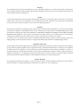
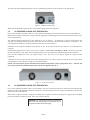
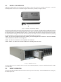
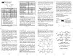
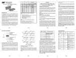
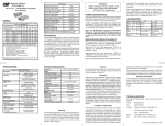
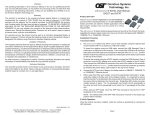
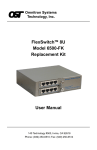
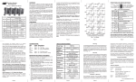
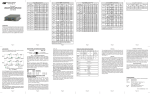
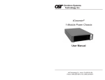
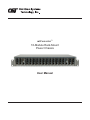
miConverter™
18-Module Rack-Mount
Power Chassis
User Manual
Warning
The operating description in this User Manual is for use by qualified personnel only. To avoid electrical shock, do not perform
any servicing of this product other than that contained in the operating instructions, unless you are qualified and certified to do
so by Omnitron Systems Technology, Inc.
Caution
All user-required operations can be performed without opening the chassis. Never attempt to open or remove the cover or tamper
with the chassis. There are no user replaceable or serviceable parts in this unit. Equipment is not intended to be installed and
used in a place (home, school, or public area) accessible to the general population.
Warranty
This product is warranted to the original purchaser against defects in material and workmanship for a period of TWO YEARS
from the date of shipment. A LIFETIME warranty may be obtained by the original purchaser by REGISTERING this product
with Omnitron within 90 days from the date of shipment. TO REGISTER, COMPLETE AND MAIL OR FAX THE ENCLOSED
REGISTRATION FORM. Or you may register your product on the Internet at http://www.omnitron-systems.com. During the
warranty period, Omnitron will, at its option, repair or replace a product which is proven to be defective.
For warranty service, the product must be sent to an Omnitron designated facility, at Buyer’s expense. Omnitron will pay the
shipping charge to return the product to Buyer’s designated US address using Omnitron’s standard shipping method.
Limitation of Warranty
The foregoing warranty shall not apply to defects resulting from improper or inadequate use and/or maintenance of the equipment
by Buyer, Buyer-supplied equipment, Buyer-supplied interfacing, unauthorized modifications or tampering with equipment
(including removal of equipment cover by personnel not specifically authorized and certified by Omnitron), or misuse, or
operating outside the environmental specification of the product (including but not limited to voltage, ambient temperature,
radiation, unusual dust, etc.), or improper site preparation or maintenance. No other warranty is expressed or implied. Omnitron
specifically disclaims the implied warranties of merchantability and fitness for any particular purpose.
Exclusive Remedies
The remedies provided herein are the Buyer’s sole and exclusive remedies. Omnitron shall not be liable for any direct, indirect,
special, incidental, or consequential damages, whether based on contract, tort, or any legal theory.
Page 2
1.0
PRODUCT OVERVIEW
The miConverter 1.5U (2.5 inch) 18-Module Power Chassis is powered by an AC or DC power supply and can accommodate
up to eighteen miConverter media converters. This compact chassis is ideal for consolidating individual media converters into
a high-density form factor utilizing a single reliable power supply. The chassis can be rack mounted in a 19” or 23” equipment
rack.
Figure 1: miConverter 18-Module Power Chassis
2.0
Model Number
Description
1020-1
miConverter 18-Module AC Powered Chassis
1025-1
miConverter 18-Module 48VDC Powered Chassis
1026-1
miConverter 18-Module 24VDC Powered Chassis
8092-0
23” rack mount brackets for 18-slot chassis
INSTALLATION PROCEDURE
2.1OVERVIEW
The following steps outline the installation procedures for the miConverter Power Chassis. Refer to the specified section for
detailed instructions.
3.0
•
Install Power Chassis (Section 3.0)
•
Install the Modules (Section 4.0)
•
Verifying Operation (Section 5.0)
INSTALL POWER CHASSIS
3.1
RACK MOUNTING
When rack mounting the chassis to a 19” standard rack, first attach the two enclosed “L” shaped rack mounting brackets to the
chassis using the enclosed screws. The rack mounting brackets can be attached to the chassis using two different hole patterns,
depending on the mounting requirement. The different hole patterns will allow two chassis to be installed in a 3U rack space.
Figure 2: Lower Rack Mount Position Figure 3: Upper Rack Mount Position
Mount and attach the chassis (after the mounting brackets are installed) to the rack using the appropriate rack mounting screws
(not provided). For optional 23” rack mounting, attach the mounting bracket in the same manner as shown above.
Page 3
The chassis provides NEBS ground posts to secure a grounding lug and wire from the chassis to the ground post.
Figure 4: NEBS Grounding Lugs
When rack-mounting this equipment, the rack should be appropriately earth-grounded.
3.2
AC POWERED CHASSIS SITE PREPARATION
Power source should be available within 5 ft. of the chassis and installed per the National Electrical Code, ANSI/NFPA-70.
Model 1020-1 requires 100-240VAC, 0.4Amp, 50/60Hz. Appropriate overloading protection should be provided on all AC power
source outlets utilized.
The standard operating temperature of this equipment is 0 to 50 degrees C. If installed in a closed or multi-chassis rack
assembly, the operating ambient temperature of the rack must not exceed the maximum rated 50 degrees C temperature. For
wide temperature models, the operating temperature must not exceed 60 degrees C.
Installation of the equipment should be such that the air flow in the front and back of the chassis is not compromised or
restricted.
Installing this equipment into a rack in such a way as to make it unstable may cause injury or death. Always make sure that
the rack is properly secured, stable, balanced and designed to carry the weight and weight distribution of this equipment.
Never use this equipment to carry any weight except its own. Never use it as a shelf to support the weight of other
equipment.
Attach the AC power cord to the back of the chassis and plug into the AC outlets. The Power LED on the front of the chassis
will illuminate as well as the Power LED on any installed modules.
NOTE: The fans will not operate until the internal ambient temperature reaches appropriately 50° C. The fans will
turn off once the internal ambient temperature drops below appropriately 40° C.
Figure 5: AC Powered Chassis
3.3 DC POWERED CHASSIS SITE PREPARATION
Power source should be available within 5 ft. of the chassis. The over current protection for the connection with centralized DC
shall be provided in the building installation and shall be a UL listed breaker rated at 15 Amps, and installed per the National
Electrical Code, ANSI/NFPA-70.
Model 1025-1 requires 36-60VDC/1.0 Amps power. Model 1026-1 requires 18-36VDC/2.0 Amps power. Appropriate overloading
protection should be provided on all DC power source outlets utilized.
WARNING: Only a DC power source that complies with
safety extra low voltage (SELV) requirements can be
connected to the DC-input power supply.
Page 4
WARNING REGARDING EARTHING GROUND:
o This equipment shall be connected to the DC supply
system earthing electrode conductor or to a bonding
jumper from an earthing terminal bar or bus to which the
DC supply system earthing electrode is connected.
o This equipment shall be located in the same immediate
area (such as adjacent cabinets) as any other equipment
that has a connection between the earthed conductor of
the same DC supply circuit and the earthing conductor,
and also the point of earthing of the DC system. The DC
system shall not be earthed elsewhere.
o The DC supply source is to be located within the same
premises as this equipment.
o There shall be no switching or disconnecting devices in
the earthed circuit conductor between the DC source and
the earthing electrode conductor.
The standard operating temperature of this equipment is 0 to 50 degrees C. If installed in a closed or multi-chassis rack
assembly, the operating ambient temperature of the rack must not exceed the maximum rated 50 degrees C temperature. For
wide temperature models, the operating temperature must not exceed 60 degrees C.
Installation of the equipment should be such that the air flow in the front and back of the chassis is not compromised or
restricted.
Installing this equipment into a rack in such a way as to make it unstable may cause injury or death. Always make sure that
the rack is properly secured, stable, balanced and designed to carry the weight and weight distribution of this equipment.
Never use this equipment to carry any weight except its own. Never use it as a shelf to support the weight of other
equipment.
Locate the DC circuit breaker and switch the circuit breaker to the OFF position.
Prepare a power cable using a three conductor insulated wire (not supplied) with a 14 AWG gauge. Cut the power cable to the
length required.
Strip approximately 3/8 of an inch of insulation from the power cable wires.
Connect the power cables to the chassis by fastening the stripped ends to the DC power connector (see Figure 6 for details on
terminal block polarity).
WARNING: Note the wire colors used in making the positive, negative and ground connections. Use the same color
assignment for the connection at the circuit breaker.
Connect the power wires to the circuit breaker and switch the circuit breaker ON. The Power LED on the front of the chassis
will illuminate as well as the Power LED on any installed modules.
NOTE: The fans will not operate until the internal ambient temperature reaches appropriately 50° C. The fans will
turn off once the internal ambient temperature drops below appropriately 40° C.
Figure 6: DC Powered Chassis
Page 5
4.0
INSTALL THE MODULES
Eighteen mounting brackets are provided with each chassis to secure the miConverter modules in the chassis. Attach the
mounting bracket to the miConverter module using the flat head screw provided (see Figure 7 below).
Figure 7: Module with Mounting Bracket
The chassis provides guides/rails to assist with the insertion of a miConverter module. Align the module with the barrel connector
towards the chassis and facing up (mounting bracket tab down). Slowly insert the module with a slight upward motion to allow
the mounting bracket to clear the button lip of the chassis. Continue inserting until the barrel connector on the chassis inserts into
the module and the mounting bracket is flush with the bottom lip of the chassis. Secure the module to the chassis by attaching
the mounting bracket to the bottom lip of the chassis using the pan head screw provided.
NOTE: The chassis only supports miConverter modules powered through the barrel connector. miConverter modules
with terminal block connectors are not supported.
NOTE: The miConverter S-Series is not compatible with the chassis.
NOTE: Remove any rubber feet from the module before installing it into the chassis.
Figure 8: Module Insertion
To remove the miConverter module, remove the screw from the mounting bracket, tilt up on the module and slide the module
out of the chassis.
5.0
VERIFY OPERATION
The chassis provides a POWER LED located on the front left top corner of the chassis. When the POWER LED is solid green,
the chassis is powered.
Page 6
6.0SPECIFICATIONS
Chassis Type
AC Powered Chassis
24VDC Powered Chassis
Module Capacity
Input Power Requirements
(typical)
100 to 240VAC 50 to 60Hz
0.4A @ 120VAC
Connector
IEC320
Compliances
+/- 18 to 36VDC
2.0A @ 24VDC
+/- 36 to 60VDC
1.0A @ 48VDC
3-pin Terminal
3-pin Terminal
UL, cUL, CE, FCC Class A
Standard Operating:
Wide Operating:
Storage:
Temperature
Dimensions
0 to 50°C
-40 to 60°C
-40 to 80°C
W: 17.5” x D: 9.5” x H: 2.5”
Weight
7.20 lbs.
Humidity
5 to 95% (non-condensing)
Altitude
-100m to 4000m
MTBF (hrs)
7.0
48VDC Powered Chassis
18
526,000
486,000
1,081,000
CUSTOMER SUPPORT INFORMATION
If you encounter problems while installing this product, contact Omnitron Technical Support:
Phone:
(949) 250-6510
Fax:
(949) 250-6514
Address:
Omnitron Systems Technology, Inc.
140 Technology Dr.
Irvine, CA 92618, USA
Email:
[email protected]
URL:
www.omnitron-systems.com
040-01020-001B
Page 7
05/12