Transcript
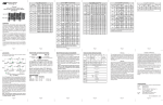
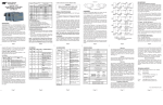
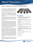
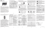
®
iConverter
100FF, OC3FF, OC12FF, 1000FF and xFF
Standalone Fiber-to-Fiber Converter
User Manual
ST/ST
SC/SC
8620-1-x
8622-1-x
8620-2-x
-
Fiber Type
(Port 1
Port 2)
8622-2-x
8622-3-x
ST/SC
8630-1-x
8631-1-x
8630-2-x
8631-2-x
8632-1-x
8633-1-x
The iConverter standalone fiber-to-fiber media converters
provide single-mode (SM) to multimode (MM), dual fiber
to single-fiber, wavelength conversion and fiber
extension. Fixed-fiber models are available for Ethernet,
Fast Ethernet, Gigabit Ethernet and SONET/SDH
applications. The Small Form Pluggable (SFP) model is
protocol transparent and also supports Fibre Channel.
8632-2-x
8633-2-x
5km
1310
1310
SM
30km
1310
1310
MM
5km
1310
1310
SM
60km
1310
1310
MM
5km
1310
1310
SM
120km
1550
1550
5 km
1310
1310
SM SF
20 km
1310
1550
MM
5 km
1310
1310
SM SF
20 km
1550
1310
8635-1-x
MM
5 km
1310
1310
SM SF
40 km
1310
1550
MM
5 km
1310
1310
SM SF
40 km
1550
1310
8634-2-x
8635-2-x
Connector
SC/SC
8642-0-x
8642-1-x
8642-2-x
8643-3-x
Tx
Rx Wavelength
Wavelength
(nm)
(nm)
MM
220/550m1
850
850
MM
1
220/550m
850
850
MM
220/550m1
850
850
SM
12km
1310
1310
MM
220/550m1
850
850
SM
34km
1310
1310
MM
220/550m1
850
850
SM
80km
1550
1550
SM
12km
1310
1310
SM
34km
1310
1310
iConverter 1000FF Single-Fiber Modules
1
220/550m1
850
850
20 km
1550
1310
SM SF
20 km
1550
1310
30 km
1310
1310
SM
12 km
1310
1310
SM SF
20 km
1310
1550
SM
12 km
1310
1310
40 km
1310
1550
SM
30 km
1310
1310
SM SF
40 km
1550
1310
8671-1-x 8675-1-x
8671-2-x 8675-2-x
ST/SC
MM
SM
8670-1-x 8674-1-x
8670-2-x 8674-2-x
1310
SM
SC/SC
1550
1310
SM SF
ST/SC
1550
1550
30 km
8661-3-x
80km
1310
SM
8660-2-x 8661-2-x
SM
20 km
1310
8660-1-x 8661-1-x
1310
SM SF
20 km
SC/SC
1310
1550
SM SF
ST/ST
12km
850
1310
Connector
SM
850
1310
8637-2-x
8643-2-x
Distances
(Port 1
Port 2)
220/550m
30 km
8637-1-x
8642-3-x
Fiber Type
(Port 1
Port 2)
MM
SM
8636-1-x
8636-2-x
MM
MM
8634-1-x
OVERVIEW:
Distances
Tx
Rx
(Port 1
Wavelength Wavelength
Port 2)
(nm)
(nm)
iConverter 100FF Single-Fiber Modules
SC/SC
iConverter OC3FF Dual Fiber Modules
iConverter 1000FF Dual Fiber Modules
iConverter 100FF Dual Fiber Modules
Connector
8650-1-x
8672-1-x 8676-1-x
8651-1-x
8673-1-x 8677-1-x
8652-1-x
8653-1-x
SM SF
20 km
1550
1310
MM
220/550m1
850
850
SM SF
40 km
1310
1550
MM
220/550m1
850
850
SM SF
40 km
1550
1310
1310
8672-2-x 8676-2-x
8673-2-x 8677-2-x
iConverter OC12FF Dual Fiber Modules
Rx
Tx
Distances
Wavelength Wavelength
(Port 1
(nm)
(nm)
Port 2)
Fiber Type
(Port 1
Port 2)
MM
5km
1310
1310
SM
30km
1310
1310
Connector Fiber Type
(Port 1
SC/SC
Port 2)
Tx
Wavelength
(nm)
Rx
Wavelength
(nm)
MM
220/550m1
1310
1310
12km
1310
1310
220/550m1
1310
1310
8681-1-x
MM
5km
1310
1310
SM
SM
60km
1310
1310
MM
MM
5km
1310
1310
SM
120km
1550
1550
iConverter OC3FF Single-Fiber Modules
MM
5 km
1310
20 km
1310
1550
MM
5 km
1310
1310
SM SF
20 km
1550
1310
MM
5 km
1310
1310
SM SF
40 km
1310
1550
MM
5 km
1310
1310
SM SF
40 km
1550
1310
SM
30 km
1310
SM SF
20 km
SM
34km
1310
1310
MM
220/550m1
1310
1310
SM
80km
1550
SC/SC
1550
1310
SM SF
20 km
1310
1550
MM
220/550m1
1310
1310
SM SF
20 km
1550
1310
SM
12 km
1310
1310
1310
SM SF
20 km
1310
1550
1310
1550
SM
12 km
1310
1310
SM SF
20 km
1550
1310
30 km
1310
1310
20 km
1550
1310
1310
SM
30 km
1310
SM SF
40 km
1310
1550
SM
30 km
1310
1310
SM SF
40 km
1550
1310
Tx
Rx Wavelength
Wavelength
(nm)
(nm)
-
-
-
-
-
-
-
-
Refer to the SFP data sheet for supported transceivers.
iConverter OC12FF Single-Fiber Modules
220/550m1
SM
8699-0-x
Distances
(Port 1
Port 2)
8681-3-x
MM
SM SF
Connector
SFP
Fiber Type
(Port 1
Port 2)
8681-2-x
1310
SM SF
iConverter xFF Dual Fiber Modules
Distances
(Port 1
Port 2)
1310
8690-1-x
8691-1-x
8692-1-x
8693-1-x
1
62.5/125µm, 100/140µm multimode fiber up to 220m. 50/125µm
multimode fiber up to 550m. Refer to the fiber cable manufacturer for
multimode distance specifications.
8650-2-x
8651-2-x
SM
12 km
1310
SM SF
40 km
1310
1550
SM
12 km
1310
1310
SM SF
40 km
1550
1310
8652-2-x
8653-2-x
1
62.5/125µm, 100/140µm multimode fiber up to 220m. 50/125µm
multimode fiber up to 550m. Refer to the fiber cable manufacturer for
multimode distance specifications.
Page 1
Page 2
Page 3
FRONT PANEL DIP-SWITCH SETTINGS:
LINK MODES:
The iConverter standalone fiber-to-fiber media converters
support two different linking modes.
Left / Down
Right / Up
Fig. 2 Front Panel Dip-Switches
Link Segment/Link Propagation “LS/LP” Dip-Switch:
This DIP-Switch has no effect. The LS function of this
DIP-Switch has been disabled to enhance compatibility
with third-party fiber optic devices. iConverter
fiber-to-fiber media converters normally operate in LP
mode.
Remote Fault Detection Switch “RFD” Dip-Switch:
When in the Remote Fault Detection “RFD” position,
the Remote Fault Detection mode is enabled and LP
mode is disabled. When in the Normal “Norm” position
(factory setting), Remote Fault Detection is disabled
and LP mode is enabled.
Fig. 1 Link Modes
LED INDICATORS:
In Link Propagate (LP) mode (sometimes referred to as
Link Loss Carry Forward), a port transmits a Link signal
only when receiving a Link on the other front-plane port,
and a loss of a received Link at one port causes the
other front-plane port to stop transmitting its link signal.
For example, P1 transmits a Link only when receiving a
Link at P2 [Fig 1(a)].
LED
Pwr:
Lk/Rx (P1):
Lk/Rx (P2):
In Remote Fault Detection (RFD) mode, a port transmits
a Link signal only when both itself and the other port are
receiving Link signals. A loss of a received Link signal
at a port is Looped-back and the port stops transmitting
a Link signal. The same loss of Link is propagated to
the other port which also stops transmitting the Link
signal. For example, the loss of Link into P2 causes
both P1 and P2 ports to stop transmission of the Link
signal [Fig 1(b)].
1. For wall-mounting, attach the converter to a wall,
backboard or other flat surface. For tabletop
installations, place the unit on a flat surface. Attach
the rubber feet to the bottom of the converter to prevent
the unit from sliding. Make sure the unit is placed in a
safe, dry and secure location.
Note: Connecting two adjacent converters which
are both set to RFD is not permitted and will cause
a “deadly embrace” lockup.
Page 7
Color
Yellow
Green
Green
Description
On--Power on
On--Link
On--Link
Off--No Link
Off--No Link
INSTALL STANDALONE MODULE AND
CONNECT CABLES
of the unit.
To power the unit using a DC power source, prepare a
power cable using a two conductor insulated wire (not
supplied) with a 14 AWG gauge minimum. Cut the
power cable to the length required. Strip approximately
3/8 of an inch of insulation from the power cable wires.
Connect the power cables to the unit by fastening the
stripped ends to the DC power connector.
Connect the power wires to the DC power source. The
Power LED should indicate the presence of power.
WARNING: Note the wire colors used in making the positive
and negative connections. Use the same color assignment
for the connection at the DC power source.
NOTE: If mounting with a safety ground attachment,
use the safety ground screw at the rear of the unit.
2. When using an SFP model (8699-0), insert the SFP
Fiber transceiver into the SFP receptacle on the module.
Note: The release latch of the SFP Fiber transceiver
must be in the closed position before insertion.
The tranceivers installed must have matching
speeds to operate.
3. Attach an appropriate multimode or single-mode fiber
cable to each fiber connector. The transmit cable (Tx)
must attach to the receive side on the other device; the
receive cable (Rx) must attach to the transmit.
4. When using single-fiber (SF) models, the Tx
wavelength on one end must match the Rx wavelength
on the other and the converters must be used in
matched pairs (example: model 8670-1 must be
matched with model 8671-1).
Page 4
FIBER-TO-FIBER SPECIFICATIONS:
Model Type
Protocols
Maximum
Data Rate
Fiber
Connectors
100FF
1000FF
OC3FF
1000BASE-SX,
100BASE-FX,
1000BASE-LX,
100BASE-BX,
1000BASE-ZX,
100BASE-LX
1000BASE-BX
OC12FF
xFF
OC-3
OC-12
100BASE-FX,
1000BASE-X, OC-3,
OC-12, OC-48,
Fibre Channel 1x/2x/4x
155Mbps
1.25Gbps
155Mbps
1.25Gbps
4.25Gbps
SC, ST,
Single-Fiber
SC
SC,
Single-Fiber
SC
SC, ST,
Single-Fiber
SC
SC,
Single-Fiber
SC
SFP
Controls
Link Propagate, Remote Fault Detection
LED
Displays
Power,
Fiber Optic Link (2)
Dimensions
W:0.85" x D:4.5" x H:2.8"
Weight
8 oz.
Compliance
UL, CE, FCC Class A,
NEBS Level 3
Power
Requirement
(typical)
5-32VDC
0.3A @ 9VDC
(1.0A max)
Temperature
Standard:
Wide:
Storage:
0 to 50º C
-40 to 60º C
-40 to 80º C
Humidity
5 to 95%
(non-condensing)
Altitude
-100m to 4000m
MTBF (hrs)
Page 5
Page 6
Warning
The operating description in this Instruction Manual is for
use by qualified personnel only. To avoid electrical shock,
do not perform any servicing of this unit other than that
contained in the operating instructions, unless you are
qualified and certified to do so by Omnitron Systems
Technology, Inc.
Limitation of Warranty
The foregoing warranty shall not apply to defects resulting
from improper or inadequate use and/or maintenance of
the equipment by Buyer, Buyer-supplied equipment, Buyersupplied interfacing, unauthorized modifications or
tampering with equipment (including repairs of equipment
by personnel not specifically authorized and certified by
Omnitron, or misuse, or operating outside the environmental
specification of the product (including but not limited to voltage,
ambient temperature, radiation, unusual dust, etc.), or
improper site preparation or maintenance.
No other warranty is expressed or implied. Omnitron
specifically disclaims the implied warranties of
merchantability and fitness for any particular purpose.
Warranty
This product is warranted to the original purchaser against
defects in material and workmanship for a period of 2
YEARS from the date of shipment. A LIFETIME limited
warranty may be obtained by the original purchaser by
REGISTERING this product with Omnitron within 90 days
from the date of shipment. To register, complete and mail
or fax the enclosed Registration Card to the indicated
address. You may also register your product on the internet
at www.omnitron-systems.com/Register. During the
warranty period, Omnitron will, at its option, repair or replace
a product which is proven to be defective.
For warranty service, the product must be sent to an
Omnitron designated facility, at Buyer’s expense. Omnitron
will pay the shipping charge to return the product to Buyer’s
designated US address (within the 48 contiguous states
and the District of Columbia) using Omnitron’s standard
shipping method.
1,300,000
Technical Support:
For help with this product, contact our Technical Support:
Phone:
(949) 250-6510
Fax:
(949) 250-6514
Address: Omnitron Systems Technology, Inc.
140 Technology Dr., #500
Irvine, CA 92618 USA
E-mail:
[email protected]
URL:
www.omnitron-systems.com
To power the unit using the AC/DC adapter, connect the
AC/DC adapter to an AC outlet. Then connect the
barrel plug at the end of the wire on the AC/DC adapter
to the 2.5mm DC barrel connector (center-positive) on
the unit. Confirm that the unit has powered up properly
by checking the power status LED located on the front
Page 8
Exclusive Remedies
The remedies provided herein are the Buyer’s sole and
exclusive remedies. Omnitron shall not be liable for any
direct, indirect, special, incidental, or consequential
damages, whether based on contract, tort, or any legal
theory.
Form: 040-08600-002A 6/10
Page 9
Page 10
Page 11
Page 12