1
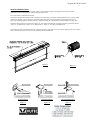
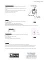
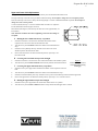
Elegante-Rev H 08/30/2010
1
INSTALLATION INSTRUCTIONS
Elegante Projection Screen
PLEASE READ THESE IMPORTANT SAFETY INSTRUCTIONS
•
Read and understand all instructions before installing and using.
•
The Elegante Projection Screen meets requirement for fire-resistant and low smoke-producing characteristics.
•
Close supervision is necessary when Projection Screen is used by or near children. Do not leave Screen unattended while
in used.
•
Installer must ensure that the mounting structures and fasteners must be of adequate strength to securely support the
screen so that vibrations or even abusive pulling on the screen surface will not cause the housing to work loose or fall.
•
The Screen Switch is provided with the symbols “O” indicating OFF, “-”indicating ON-UP and “=” indicating ONDOWN.
•
Do not operate Screen with a damage cord or if the Screen has been dropped or damage – until it has been examined by a
qualified serviceman.
•
DO NOT place or attach anything to metal casing or viewing screen.
•
Position cord so that it will not be tripped over, pulled, or contact hot surfaces.
•
DO NOT plug the cord in with wet hands; electric shock could occur
•
•
•
DO NOT under any circumstances cut or remove the third (Ground) prong from power cord. For personal safety, this
Projection Screen must be properly grounded.
Always unplug Projection Screen from electrical outlet before cleaning and servicing and when not in use. Never Yank
cord to pull cord from outlet. Grasp plug and pull to disconnect.
To reduce the risk of electric shock, do not dissemble this Projection Screen, but take it to a qualified serviceman when
service or repair is required. Incorrect reassembly can cause electric shock when Screen is used subsequently,
Cord and Plug Installation Safety Instructions
•
The length of power cord used in this Projection Screen was selected to reduce the hazards of becoming tangled in, or
tripping over a longer cord.
•
We strongly recommend against the use of an extension cord.
•
If an extension cord is necessary, it is absolutely necessary that it is UL-Listed, 3-wire grounding type appliance
extension cord having a grounding type plug and outlet. The electrical rating of the extension cord must be equal or
greater that the rating of the projection screen.
•
Always unplug Projection Screen from electrical outlet before cleaning and servicing and when not in use. Never Yank
cord to pull cord from outlet. Grasp plug and pull to disconnect.
•
Always connect this Projection Screen to a grounded outlet. Outlet–socket should be located near Screen and shall be
easily accessible
“SAVE THESE INSTRUCTIONS”
Elegante-Rev H 08/30/2010
2
General Installation Notes
The Elegante screen can be mounted on a wall, ceiling or suspended from ceiling. The Elegante Projection Screen meets
requirement for fire-resistant and low smoke-producing characteristics.
The screen surface is centered in the housing
The brackets should be mounted into studs or blocking in the wall/ceiling or in drywall (minimum thickness [1/2”] with specified
anchors (not supplied). For any other type of installation and other types on non-wood frame construction, the selection of
appropriate mounting hardware should be made by a qualified installer and it should follow all local building and safety codes
Determine bracket location per instructions in Figure 1a. And configure mounting kit according to mounting preferences show in
“Figure 1c” for Wall mount, “Figure 1d” for ceiling mount or “Figure 1e” for ceiling suspended mount.
The mounting structures and fasteners must be of adequate strength to support the screen even abusive pulling on the screen surface
will not cause the housing to work loose or fall. Housing must be mounted level
Figure 1a
Figure 1b
Wall Installation
Ceiling Installation
Suspended Installation
Figure 1c
Figure 1d
Figure 1e
Elegante-Rev H 08/30/2010
3
Wall Installation
Referring to Figure 1a, measure the Full Length of the housing and determine Dim K for brackets’ locations. Mount the brackets to
the wall with suitable fasteners. Be sure the brackets are level.
Follow the steps in Figure 2. Note, screen housing can be move side to side once it is hung in the brackets.
Figure 2
Under Ceiling Installation
Follow the steps in Figure 3. Note, screen housing can be move side to side once it is hung in the brackets.
Elegante-Rev H 08/30/2010
4
Suspended Installation
Attach chain links or steel cables (not supplied) to beams or other structural
members.
Install an Eyebolt (supplied) to each bracket (Figure 4). Tighten the hex nuts of
Eyebolt.
Install the brackets to the housing per Dim K as shown in Figure 1a. Tighten
the locking screws to hold the brackets in place.
Hang the screen and be sure it is level.
Electrical
The screen is equipped with an in-line 3-position rocker switch for operation.
No wiring is necessary.
Figure 4
The switch has the UP – OFF – DOWN positions (Figure 5).
All operating switches should be off before power is connected.
Plug the power cable to an easily accessible 120VAC outlet near the Elegante Projection Screen. The screen is ready for use.
120VAC motor
White
Neutral
Black
AC Hot
Green
Ground
Motor Specifications:
Asynchronous motor, capacitor start, 3-stage planetary gear reduction, bi-directional,
intermittent duty.
120VAC, 60HZ, 1.2A, 33RPM, 110Watt
Built-in limit switches
Figure 5
Electromagnetic disk brake, Thermo-overload protection
Operation
Before operating the screen, remove tape and/or foams securing the screen to the housing.
Flip the rocker switch down to lower the screen. The screen will stop automatically when it reaches the lower limit.
Flip the rocker switch up to raise the screen. The screen will stop automatically when it reaches the upper limit.
The screen may be stopped in any intermediate position by returning the rocker switch to the center “OFF” position.
Elegante-Rev H 08/30/2010
5
Upper and Lower Limit Adjustments
The upper and lower limits of the screen have been factory set to the maximum allowable travels.
The upper limit stop is when the screen just draws inside the housing. Do not adjust or change the screen to higher position.
The lower limit stop of the screen is always the Viewing Height + 6 inches of maximum allowable top leader. Do not adjust or
change the screen to lower position.
A 5/32 inch (4mm) hex key or a 1/8 inch wide flat blade screwdriver is required to
turn the motor limit switches (Figures 1b and 5).
Each full turn (360 degrees) of the hex key will move the screen approximately 1/2
inch (19mm).
Note: Clockwise rotation is the same as tightening a screw into the ceiling. No
exception!
A Raising the lower limit from factory set position
1-
Send the screen down to its lower limit. Determine the number of turns
required to move the screen above the desired lower limit.
2-
Turn the hex key in the clockwise rotation the number of turns determined in
step 1.
3-
Send the screen up halfway then stop. Send the screen down. The screen
should stop above the desired lower limit.
4-
If the screen lower limit is not above the desired position, repeat steps 1 to 3.
Proceed to Part B.
B Lowering the lower limit from previous changed
1-
Send the screen down to its lower limit. The switch must remains in the ‘DOWN’ position.
2-
Turn the hex key in the counter-clockwise rotation slowly until the desired lower limit is reached.
Limit Switch Sockets as
C Lowering the upper limit from factory set position
Figure 5
viewed through housing
looking up
1-
Send the screen up to its upper limit. Determine the number of turns required to move the screen below the desired upper
limit.
2-
Turn the hex key in the clockwise rotation the number of turns determined in step 1.
3-
Send the screen down halfway then stop. Send the screen up. The screen should stop below the desired upper limit.
4-
If the screen upper limit is not below the desired position, repeat steps 1 to 3. Proceed to Part D.
D Raising the upper limit from previous changed
1-
Send the screen up to its upper limit. The switch must remains in the ‘UP’ position.
2-
Turn the hex key in the counter -clockwise rotation slowly until the desired upper limit is reached.