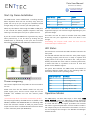
1
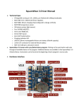
Pixie User Manual
Document PN: 50478 (F)
for more info please visit:
www.enttec.com/pixie
ENTTEC PIXIE DRIVER
DMX/USB PIXEL LED STRIP DRIVER
Features
•
Drives 2 DMX universes worth of 5 Volt PIXEL
LED strips
•
In-Built 5V DC power supply with 55 and 110
watts output power units available (pn: 73540 and
73451)
•
In-Built 12V DC power supply with 65 and 130
watts output power units available (pn: 73542 and
73453)
•
DMX512 Controllable and USB configurable
•
Supports RGB pixel strips based on WS2812 &
WS2812B LEDs.
•
Quick 2 steps test installation: connect your pixel
strips to the screw terminal output and plug
mains cable to a wall outlet. It is that easy!
•
Stand-alone test output sequences (no external
data required)
•
Show record and playback (Art-Net to usb using
PRO-Manager App)
•
Power and output status LED indicators
•
Small, light and easy to hide design
•
High quality powder coated metal box
•
Scalable design for large projects
•
Up to 8 units stackable using standard 19” modular
rack accessory (sold separately)
•
Ideal for custom shape pixel LED installations
•
Standard IEC mains
connectors
•
Plug-unplug screw terminal output connector
•
Automatic multi voltage mains input (110-250V AC)
and 5Pin-XLR DMX input
Safety
•
This unit is intended for indoor use only
•
Do not expose the PIXIE DRIVER to rain or moisture,
doing this will void the warranty
•
Make all the connections before you plug in the
main power
•
Do not remove the cover, there are no serviceable
parts inside
•
Never plug this unit in to a dimmer pack
•
Always be sure to mount this unit in an area that will
allow proper ventilation. Allow about 6” (20 cm)
between this device and a wall
•
Power-supply cords should be routed so that they
are not likely to be walked on or pinched by items
placed upon or against them, paying particular
attention to the point they exit from the unit
1
Pixie User Manual
Document PN: 50478 (F)
for more info please visit:
www.enttec.com/pixie
Start-Up Demo Installation
The PIXIE Driver comes loaded with a scrolling rainbow
demo sequence which will run and loop every time you
power the unit up so you can get your installation tested
straight away once you connect your LED pixel strips.
When any valid data is fed through the DMX or USB ports
it will override the demo playback sequence and keep
listening to the data ports until you re-power the unit.
If you do not want the PIXIE driver to generate any output
when powered up, it can be done by erasing the pre
loaded show or overwriting it with your own as further
described in the ENTTEC PRO Manager software section.
Power Source
55W
110W
VCC
300 RGB LEDs
300 RGB LEDs
VCC0
Unused
300 RGB LEDs
TOTAL:
300 LEDs
600 LEDs
Use the information in the table to define the maximum
supported strips per unit and the length depending on your
particular design.
This table can also be used to calculate how many PIXIE
drivers will suit your application when one driver is not
enough.
Overloading the outputs could cause the unit and the
connected strips to malfunction.
LED Status
The Pixie driver comes with two LED indicators located in the
front panel.
The red LED indicates that the internal 5 Volts power supply
is working properly and the unit is ready to operate and
supply power to the strips. If the LED is OFF and you have
already connected the mains cable to a working wall outlet,
it means that there is a problem in the unit. In such case
please contact ENTTEC support.
The green LED indicates the PIXIE status and should be
constantly flashing. Please refer to the following table for
information about current operating status:
Flashing Frequency
Unit Status
0 Hz
Error Occurred
Power Budgeting
0.5 Hz
Unit is running normally
This section explains how many LEDs can be connected to
the unit.
2 Hz
Show is playing
8 Hz
Receiving data from DMX
25 Hz
Receiving data from USB
Please note that the the 55Watt model has only one
power supply (VCC) and the VCC0 output will not be
available. The 110Watt unit has two internal power
supplies.
(VCC and VCC0) which can not be connected in parallel.
The strips supported by the PIXIE driver are based on the
WS2811, WS2812 and WS2812B LEDs; the following table
shows the maximum number of LEDs per power source
output that the driver could handle when these are driven
to their maximum power (full RGB white).
Operation Modes
The PIXIE Driver can drive LED strips in three ways: DMX
mode, Playback mode and additionally testing sequences
can be sent through USB. It is only possible to use one mode
at a time and the one with higher precedence will override
the others. A general explanation of all the modes is made in
this chapter and you can find further information on how to
use and configure the settings in the ENTTEC Pro Manager
software section.
2
Pixie User Manual
Document PN: 50478 (F)
for more info please visit:
www.enttec.com/pixie
USB (testing)
Input Data
Highest
Precedence
DMX
PLAYBACK
Middle
Lowest
USB (testing sequences)
The USB 2.0 port is mainly used to configure the unit and
download new shows. It also allows test sequences to be
run through the free application as described in the Pro
Manager software section.
E.g. The shortest possible show with 510 channels at 40
frames per second, will be 25 seconds, although its length
can be increased dramatically if the recording parameters
are lowered or the show speed is lower.
If the show has a repetitive nature you could also get it to
loop-back forever.
Remember that any data coming from DMX or USB ports will
override the playback mode.
Reference Design
When running the testing sequences all other modes will
be overridden by the USB port as it has the highest
precedence.
DMX mode
When data is fed through the DMX ports and there is no
active USB sequence, this will be reflected on the strips
outputs D1 and D2.
By default the data coming from DMX1 connector will be
sent to the beginning of the strips (section 1) through D1
and D2 outputs and the data coming from DMX2 will be
sent to section 2 through both outputs.
The full DMX LED strip update message format is shown
below assuming that an RGB strip is being used. If the
DMX message has less than 512 slots other than the start
code, the data for missing slots will be zero.
Size In
Description
Bytes
1
Must be 0 or frame will be ignored since it is not DMX.
3
R1, G1, B1. 8 bit intensity of each color of first LED pixel.
3
R2, G2, B2. 8 bit intensity of each color of second LED pixel.
...
…
3
R170, G170, B170. 8 bit intensity of each color of last LED pixel.
PIXIE driver supports any kind of DMX output device. Here is
a reference diagram of connections.
Playback mode
Trigger the stored show from the Pro Manager software
or by configuring the PIXIE to start playing it on power
up.
The PIXIE driver comes with a pre-loaded scrolling
rainbow sequence which will playback and loop forever
on power up and there are more available pre recorded
sequences included with the pro manager software in the
Enttec website.
The maximum length of the show depends on the
recording parameters.
3
Pixie User Manual
Document PN: 50478 (F)
for more info please visit:
www.enttec.com/pixie
PIXIE Driver USB support
The PIXIE is supported by FTDI drivers for the following
Operating Systems:
•
Windows XP, Windows Server 2003, Windows
Vista, Windows Server 2008,
Windows 7, Windows 8, Windows Server 2008
R2. (32 bit
and
64 bit versions)
•
Mac OS X (Mac OS X 10.6 or later )
•
Linux/BSD
PRO-MANAGER
Once the driver has finished installing, you may now power
up the PIXIE and plug in the micro USB cable to connect the
device to your computer. One end, the micro USB (smaller
connector) plug, will fit the USB port in the unit. The other
end, which is wider and almost flat in comparison, goes to
any available USB port in your computer or you may also
plug it into a USB hub.
When you make the connection to your computer, a
message should appear (usually a few seconds later in
Windows) saying your computer has detected new hardware.
It will be correctly identified as ENTTEC PIXIE Driver by your
computer.
ENTTEC provides a free cross-platform (Windows & Mac
only) application to configure, test and update the PIXIE.
It also allows the user to record a Artnet show into the
memory and set-up the standalone mode. The application
is available for Windows or Mac from the ENTTEC website.
•
Use this application to test, troubleshoot and
update the PIXIE, record, playback, set-up
standalone shows, send Art-Net and predefined
output pixel patterns to your strips.
•
This application is merely a testing tool and not
Lighting Control software.
This manual will cover the Windows 7™ installation
process, by way of example. Others will be similar, but the
particulars of how each operating system works in terms
of screen shots have been omitted for brevity.
Before plugging in your PIXIE to your computer, please
install the driver, by installing the PRO Manager software
available from Enttec website. Select “YES” when you are
asked to install FTDI drivers and follow the installation
wizard.
“Devices” Tab
From the PRO Manager Home page, you can click the “Find
Devices” button to search for Enttec devices connected to
your computer. Once it finds it, please select the PIXIE from
the selection box to start communication.
Once selected, you will see all the device information on the
Home Page , from here you can configure Settings and
update the firmware on the PIXIE.
4
Pixie User Manual
Document PN: 50478 (F)
for more info please visit:
www.enttec.com/pixie
Firmware Update
LED Strip protocol
Use the latest firmware file meant for PIXIE driver
available on the ENTTEC website and upload it using the
upload button (“Choose File” - as per Chrome browser).
Allows compatibility amongst the supported protocols
(WS2811, WS2812, WS2812b). Please check your strip to see
which protocol it supports.
Run show on DMX loss
After selecting the correct file, click on the Update
Firmware button and let the update proceed.
Once Finished, the page will automatically refresh, and
device information will be updated to reflect the updated
firmware.
Pixie Settings
Available on firmware 1.5 & onwards, settings can now be
changed from the Home page itself.
If standalone show is programmed onto Pixie, and this
option is set to Yes and, if no DMX input is received, the
show will be played back. (3 seconds timeout for DMX input)
Pixel RGB Mapping
Allows the default order of RGB mapping to be changed on
the Pixie, usually to conform with non-standard mapping.
This setting applies to all RGB data sources: DMX, USB, and
show replay.
The default RGB mapping assumes that both the DMX input
and the led strip outputs are in RGB order.
For example, if the led-strips have GRB ordering, you can
change this option to GRB here, and Pixie will map the
colours correctly. This avoids having to change the DMX
source RGB order to conform to the strip.
“SEND” Tab
DMX Personality
Allows the DMX route to be changed.
Personality1: Both outputs (D1 & D2) are mapped to
both DMX inputs (DMX1 drives section1 and
drives section2)
It is possible to send pre-defined testing sequences,
personalised data or Art-Net packets coming from any
external source to your strips using the tools provided in this
window.
DMX2
Personality2: DMX1 is mapped to D1 only, and DMX2 is
mapped to D2 only.
Additional setting for Personality2, allows the physical
LED pixels to be grouped onto desired number of DMX
pixels. (patching more than 1 LED pixel to a group of DMX
channels – RGB inclusive)
How these personalities can be used is discussed further
under “Application Usage”
Select one out of the three available sources: “Test Patterns”,
“Live Artnet” or “From Faders”. Then select the Output
configuration depending on your particular wiring need.
The Test Patterns mode will start sending predefined
sequences to your strips once you select the desired one
from the drop down.
The Live Art-Net section will allow the user to send any
incoming valid Art-Net data straight to the pixel strips whilst
5
Pixie User Manual
Document PN: 50478 (F)
for more info please visit:
www.enttec.com/pixie
the pro manager is running and a USB cable is connected.
Please select the matching start universe and make sure
the Art-net data is being sent to your computer IP
address or broadcasted.
PRO-Manager will show the mapping from universe to
sections on each output, based on your selections.
Closing or changing the Send window, will stop Art-Net
to Pixie send, PRO-Manager only sends to Pixie while on
this page.
than a selected value. Once the configuration is all set, you
can click on “Record Art-Net” button to start recording the
show.
The recording is saved to a file, and is only transferred to the
memory when recording is stopped by using the “Stop
Recording” button or driving the trigger channel to the right
value. Whilst recording, live data is sent to the strips, so you
can decide when to stop.
The recording can now be transferred to memory using
“Write to Memory” button and the upload to memory
progress is shown as it happens.
Finally, data can be sent to any particular pixel by using
the channel faders which allow you to adjust the intensity
of any desired LED on the strip.
Once the show is uploaded to memory successfully, the page
is automatically refreshed to allow show control on the
recorded show.
“Standalone” Tab
Standalone mode allows you to record (and playback)
shows via Art-Net input to PIXIE memory. The duration of
the recording depends on the configuration selected
before recording. The recorder is smart enough to only
record changes in the frames, so as to accommodate as
many frames as possible.
The show can now be played and stopped using the controls
on this page. These controls will only be available, if there is
a show stored in memory.
You can also export and import recorded shows using the
“Export Show to File” or “Import Show to PIXIE Driver”
buttons.
Application Usage Examples
Depending on usage, Pixie Driver can be setup to be used in
different ways. Following are some examples that will
highlight these:
Drive 300 leds from one DMX Universe
Strip used: 8PL-60-F (5M of Smart Pixel Tape)
The recording trigger feature will let you select a channel
in your show to start/stop the recording when it is greater
Pixie is setup to use DMX Personality2, with pixel grouping
set to 2.
6
Pixie User Manual
Document PN: 50478 (F)
for more info please visit:
www.enttec.com/pixie
This setup allows you to map 450 channels of DMX to 300
LEDs (each RGB DMX address is mapped to 2 pixel LEDs)
Physical Dimensions
You can even use less DMX channels (with a higher pixel
grouping) to drive the entire 300 LEDs.
The unit is designed to fit the modular rack accessory (sold
separately) which allows stacking up to 8 units in a standard
19” rack using 3 standard rack mount units (3RU).
Pixie 55W driver will only support DMX1 in this scenario,
however Pixie 110W driver can be used to drive 300 LEDs
each from both DMX1 & DMX2
Stackable Modular Rack (Accessory)
Fig: Drive 300 leds from one DMX Universe (110W)
Drive 300 leds from DMX1 & DMX2 (combined)
Strip used: 8PL-60-F (5M of Smart Pixel Tape)
Pixie is setup to use DMX Personality1
This setup allows you to map DMX1 to the first section
(170 leds) and DMX2 to the second section (remaining
130 leds) – allowing upto 300 leds in total
The modular rack (sold separately) allows up to 8 Pixie units
to be stacked up using only 3 standard rack units (3RU). Also
has an in-built fan at the rear side.
Fig: Drive 300 leds from DMX1 & DMX2 (combined)
7
Pixie User Manual
Document PN: 50478 (F)
for more info please visit:
www.enttec.com/pixie
Specifications
Due to continuous improvements and innovations of all
ENTTEC products, specifications and features are subject
to change without notice.
Item
Value
Input Voltage
110 – 240V AC
Input Frequency
50/60Hz
Maximum Total
Output Power
55W and 110W versions (5V)
65W and 130W versions (12/24V)
Ordering Information
The PIXIE DRIVER and compatible products can be ordered
from our website or through your ENTTEC dealer using the
following part numbers. Different voltage and protocol units
are made under special order (please contact us).
Part Number Description
73541
PIXIE DRIVER 5V (55 WATTS)
73540
PIXIE DRIVER 5V (110 WATTS)
Maximum Current per
11 Amps
source (VCC or VCC0)
73542
PIXIE DRIVER 12V (65 WATTS)
Maximum Current per
10 Amps
Pin (Screw Terminal)
73543
PIXIE DRIVER 12V (130 WATTS)
73547
PIXIE DRIVER 24V (65 WATTS)
73548
PIXIE DRIVER 24V (130 WATTS)
73545
PIXIELINKER (5V)
73550
8 WAY PIXIE RACK
73527
STACKABLE RACK ADAPTER PLATE FOR PIXIE
8PL144-2
144 LEDS/M Pixel tape – 2 Meter Roll
Data Output Type
Serial WS2812 & WS2812B supported
Data Output Channels 4
Control Input
DMX512
Show Recording
From Art-Net using Pro Manager
software
Show
Download/Upload
Through USB port
Cooling Method
Convection
8PL30-F
30 LEDS/M Pixel tape - 5 Meter Roll
Ambient Working
Temperature
5° to 40° C
8PL60-F
60 LEDS/M Pixel tape - 5 Meter Roll
2x 5-Pin Male XLR for DMX input
1x Double layer 6-Pin screw terminal
1x 3-Pin IEC C14 Male Socket 10Amps
8PL144-1
144 LEDS/M Pixel tape – 1 Meter
Connectors
8PL30-1
30 LEDS/M Pixel tape – 1 Meter
Protection Rating
IP20
8PL60-1
60 LEDS/METRE Pixel tape – 1 Metre
ENTTEC PTY LTD
17/5 Samantha Court
Knoxfield Victoria 3180
Australia
Tel: +61 3 9763 5755
Fax: +61 3 9763 5688
ENTTEC AMERICAS
604A Cornerstone Ct.
Hillsborough NC 27278
USA
Tel-Fax: (888) 454-5922
email [email protected]
www.enttec.com
8