1
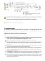
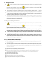
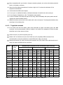
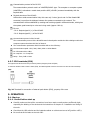
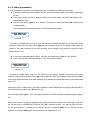
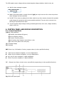
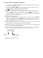
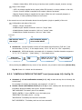
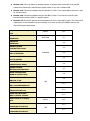
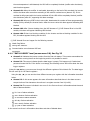
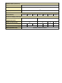
HI-TECH PRO UNINTERRUPTIBLE POWER SUPPLY USER MANUAL [email protected] / www.tuncmatik.com GENERAL INDEX 1. INTRODUCTION 1-1. GRATEFULNESS LETTER 1-2. USİNG THİS MANUAL 1-2-1. Used Symbols 1-2-2. For More Information & Help 2. QUALITY AND STANDARD GUARANTEE 2-1. STANDARD 2-2. ENVİRONMENT 3. PRESENTATION 3-1. VİEWS 3-1-1. Views of the equipment 3-1-2. Corresponding legends to the equipment views 3-2. DEFİNİTİON AND STRUCTURE 3-2-1. Structural Scheme 3-3. OPERATİNG PRİNCİPLE 3-3-1. Normal operation, () 3-3-2. Operation with mains failure, () 3-3-3. Operation with inverter not active, () 3-3-4. Operation in manual bypass, () 4. INSTALLATION 4-1. IMPORTANT SAFETY INSTALLATİON 4-1-1. Batteries safety instructions 4-1-2. To get into account 4-2. EQUİPMENT RECEPTİON 4-2-1. Unpacking and content checking 4-2-2. Storage 4-2-3. Transport to location 4-2-4. Location 4-3. CONNECTİON 4-3-1. To the mains connection, terminals 4-3-2. Independent static bypass line connection, terminals (X14 to X17). Only in versions UPS-B 4-3-3. Connection of the output, terminals (X6 to X9) 4-3-4. Connection main protective earthing terminal ( bonding terminal ( ) 4-3-5. COM port relays. Connector (X32) 4-3-6. Port COM RS-232 & RS-485. Connector (X32). 4-3-7. EPO terminals (X50) 5. OPERATION 5-1. START UP 5-1-1. Control before start up )and protective earth 5-1-2. Start up procedure 5-2. COMPLETE UPS SHUTDOWN 5-3. EMERGENCY POWER OFF (EPO) OPERATİON 5-4. BYPASS MANUAL SWİTCH (MAINTENANCE) 5-4-1. Principle of operation 5-4-2. Transfer to maintenance bypass 5-4-3. Transfer to normal operation 6. CONTROL PANEL AND DISPLAY DESCRIPTION 6-1. CONTROL PANEL PARTS 6-2. BASİC FUNCTİONS OF KEYBOARD FROM SYNOPTİC 6-2-1. Messages menus and classification in submenus 6-3. SCREEN DESCRİPTİON 6-3-1. Main level (screen menu 0.0). See Fig. 30 6-3-2. ‘‘CONTROL & STATUS OF THE UNIT” Level (screen menu 1.0). See Fig. 31. 6-3-3. ‘‘PARAMETERS’’ level (screen menu 3.0). See Fig. 33. 6-3-4. ‘‘ALARMS’’ level (screen menu 4.0). See Fig. 34 6-3-5. ‘‘DATA LOGGER’’ level (screen menu 5.0). See Fig. 35 6-3-6. ‘‘CONFIGURATION’’ level (screen menu 6.0). See Fig. 36. 6-3-7. Rated values screens (screen menu 7.0). See Fig. 37 7. ANNEXES 7-1. GENERAL TECHNİCAL SPECİFİCATİONS 1. INTRODUCTION 1-1. GRATEFULNESS LETTER We would like to thank you in advance for the trust you have placed in us by purchasing this product. Read this instruction manual carefully before starting up the equipment and keep it for any possible future consult that can arise. We remain at you entire disposal for any further information or any query you should wish to make. Yours sincerely The equipment here described can cause important physical damages due to wrong handling. This is why, the installation, maintenance and/or fixing of the here described equipment must be done by our staff or specifically authorized. According to our policy of constant evolution, we reserve the right to modify the specifications in part or in whole without forewarning. 1-2. Using This Manual The target of this manual is to give explanations and procedures for the installation and operating of the equipment. This manual has to be read carefully before installing and operating it. Keep this manual for future consults. This equipment has to be installed by qualified staff and, the simple help of this manual, it can usable by personnel without specific training 1-2-1. Used Symbols «Warning» symbol. Carefully read the indicated paragraph and take the stated prevention measures. «Danger of electrical discharge» symbol. Pay special attention to it, both in the indication on the equipment and in the paragraph referred to this user’s manual. «Main protective earthing terminal» symbol. Connect the earth cable coming from the installation to this terminal. «Earth bonding terminal». Connect the earth cable coming from the installation to this terminal. «Notes of information» symbol. Additional topics that complement the basic procedures. Preservation of the environment: The presence of this symbol in the product or in their associated documentation states that, when its useful life is expired, it will not be disposed together with the domestic residuals. 1-2-2. For More Information & Help For more information and/or help of the version of your specific unit, request it to our Service and Technical Support. 2. QUALITY AND STANDARD GUARANTEE 2-1. Standard The UPS series product is designed, manufactured and commercialized in accordance with the standard EN ISO 9001 of Quality Management Systems. The marking shows the conformity to the EEC Directive (quoted between brackets) by means of the application of the following standards 2006/95/EC Low voltage directive. 2004/108/EC Electromagnetic Compatibility directive (EMC) EN-IEC 62040-1. Uninterruptible power supply (UPS). Part 1-1: General and safety requirements for UPS’s used in accessible areas by end users. EN-IEC 60950-1. IT equipments. Safety. Part 1: General requirements. EN-IEC 62040-2. Uninterruptible power supply (UPS). Part 2: Prescriptions for Electromagnetic compatibility (EMC). EN-IEC 62040-3. Uninterruptible power supply (UPS). Part 3: Methods of operation specification and test requirements. The manufacturers responsibility is excluded in the event of any modification or intervention in the product by the customer’s side. 2-2. Environment This product has been designed to respect the environment and has been manufactured in accordance with the standard ISO 14001. Equipment recycling at the end of its useful life: Our company commits to use the services of authorized societies and according to the regulations, in order to treat the recovered product at the end of its useful life (contact your distributor). 3. PRESENTATION 3-1. Views 3-1-1. Views of the equipment Fig. 2. Cabinet front view for UPS up to 20kVA Fig. 3. Cabinet front view for UPS from 30 to with front door closed. 80kVA with front door closed. Fig. 4. Control panel view * Only in optional version UPS-B (Static Bypass line independent). Fig. 5. Cabinet front view for UPS up to 20kVA Fig. 6. Cabinet front view for UPS up to 30 to with front door opened and configuration of three 80kVA with front door opened and configuration of phase input / three phase output. three phase input three phase output. * Only in optional version UPS-B (Static Bypass line independent). Fig. 7. Cabinet front view for UPS up to 20kVA Fig. 8. Cabinet front view for UPS from 30 to with front door opened and configuration of three 80kVA with front door opened and configuration of phase input / single phase output. three phase input / single phase output. (Optional, only modified by manufacturer) (Optional, only modified by manufacturer) * Only in optional version UPS-B (Static Bypass line independent). Fig. 9. Cabinet front view for UPS up to 20kVA Fig. 10. Cabinet front view for UPS from 30 to with front door opened and configuration of single 80kVA with front door opened and configuration of phase input / single phase output. single phase input / single phase output. (Optional, only modified by manufacturer) (Optional, only modified by manufacturer) * Only in optional version UPS-B (Static Bypass line independent). Fig. 11. Cabinet front view for UPS up to 20kVA Fig. 12. Cabinet front view for UPS from 30 to with front door opened and configuration of single 80kVA with front door opened and configuration phase input / three phase output. of single phase input / three phase output. (Optional, only modified by manufacturer) (Optional, only modified by manufacturer) 3-1-2. Corresponding legends to the equipment views Protection and handling elements (Q*): (Q1a) Input circuit breaker or switch according to power of the equipment. (Q2) Output switch. (Q3) Battery fuse holder switch with 3 fuses (models up to 40 kVA) or switch (for higher models). (Q4) Static bypass (Only in optional version -B). (Q5) Maintenance bypass switch. (Q8) Battery fuse holder switch 3 fuses, located in the battery cabinet. Connecting elements (X*): (X1) Phase input terminal R. (X2) Phase input terminal S. (X3) Phase input terminal T. (X4) Neutral input terminal N. (X5) Main protection earthing terminal ( ). (X6) Phase output terminal U. (X7) Phase output terminal V. (X8) Phase output terminal W. (X9) Neutral output terminal N. (X10) Earth bonding terminal for load or loads and/or battery cabinet ( ). (X11) Batteries terminal +(Only for external battery model). (X12) Batteries terminal –(Only for external battery model). (X14) Phase static bypass terminal R (Only in optional version -B). (X15) Phase static bypass terminal S (Only in optional version -B). (X16) Phase static bypass terminal T (Only in optional version -B). (X17) Neutral static bypass terminal N (Only in optional version -B). (X23) Batteries terminal N (middle tap, Only for external battery model). (X31) DB9 connector COM RS-232 and RS-485 ports. (X32) DB9 connector relay interface. (X47) Batteries terminal + of external batteries cabinet. (X48) Batteries terminal – of external batteries cabinet. (X49) Batteries terminal N (middle tap) of external batteries cabinet. (X50) Terminals for external EPO. Keyboard and optical indications control panel (PC): (LCD) Display LCD. (ENT) Key «ENTER». (ESC) Key «ESC». () Key move up. () Key move down. () Key move to right. () Key move to left. (a) Rectifier Input Voltage OK led (green). (b) Output voltage unit from the Bypass led (orange). (c) Inverter is working led (green). (d) Unit working from batteries -mains failure- led (red). (e) General alarm. In case of any alarm of the unit led (red). Other abbreviations: (BL) Mechanical block for manual bypass switch (Q5). (CL) Lock for cabinet front door. (PB) Levelers and immobilizing elements. (PC) Control panel. (PF) Cabinet front door. (PR) Cable stuffers or wire cones. (RD) Scroll wheel. (SL) Slot for optional intelligent card. (TB) Terminal cover. (TS) Slot cover (SL). (t1) Screws fixing for terminals cover (TB). (t2) Screws fixing for mechanical block (BL) for switch (Q5). (t3) Screws fixing for slot cover (TS). 3-2. Definition and structure 3-2-1. Structural Scheme In single line diagrams of figures 17 and 18 show, as an example, the basic structure of a standard equipment and another one with separate bypass line, for a three phase input and output configuration. For any other configuration, the quantity of cables and terminals at the input, output and bypass will only vary; internal structure of the equipment will never do it. Fig..17. UPS block diagram with operating flows. In equipments with separate bypass line, an isolation transformer must be placed at any of both input power supply mains of the UPS (rectifier input or static bypass), in order to avoid the direct connection of the neutral of both mains through the internal wiring of the equipment. Fig. 18. UPS-B block diagram with operating flows. 3-3. Operating principle This online UPS is a double conversion system AC/DC, DC/AC with a sine wave output that gives safe protection in extreme conditions of power supply (variations in voltage, frequency, electrical noises, blackout and micro cuts, etc…). Whatever the kind of load that has to be protected, these devices are prepared to assure quality and continuity in the electrical supply. The operation is basically as follows: Rectifier, an IGBT three phase rectifier, converts the AC voltage into DC by absorbing a pure sine wave current (THD <2%), and charging batteries at constant current / voltage. The batteries supply the power needed by the inverter in the event of mains failure The Inverter deals with transforming the voltage of the DC bus into AC by providing a sine-wave, alternating output stabilized in voltage and frequency suitable for supplying the loads connected on the output. The basic double conversion structure is complemented by two new functional blocks, the static bypass commuter switch and the manual bypass commuter switch The static bypass commuter switch connects the output load directly to the bypass network in special circumstances such as overloading or overheating and reconnects it to the Inverter when normal conditions are restored The UPS-B version has separate lines for the Inverter and bypass blocks, thus increasing the safety of the installation, as it allows the use of a second mains (generator unit, other company, etc…) The manual bypass commuter switch isolates the UPS from the mains and from the loads connected on the output, so that maintenance operations may be performed in the UPS without any need to interrupt the supply to the loads. 3-3-1. Normal operation, () With the mains present, the rectifier transforms the AC input voltage into DC raising the DC voltage to a suitable level for supplying the inverter and to charge the batteries. The inverter deals with transforming the voltage of the DC bus into AC, providing a sine wave alternating output, stabilized in voltage and frequency to supply the loads connected to the output (figures 17 and 18). 3-3-2. Operation with mains failure, () In the event of mains failure or should a micro cut occur, the group of batteries supplies the power needed to supply the inverter. The inverter continues working normally without appreciating the lack of mains and the back-up time of the device depends only on the capacity of the group of batteries (figures 17 and 18). When the battery voltage reaches end of back-up time, the control blocks the output as protection against a deep battery discharge. When the mains returns and following the first seconds of analysis, the UPS operates once more as in section «Normal operation». 3-3-3. Operation with inverter not active, () The inverter is inactive due to the existence of alarm conditions such as overloads, overheating, end of back-up time, etc… In that cases the rectifier continues charging the batteries to maintain their optimal charge state. The inverter is also inactive if the unit has not been started up with the keyboard. In that case, the rectifier will be inactive. In all these cases the output voltage of the UPS is supplied by the emergency bypass line through the static bypass commuter switch (figures 17 and 18), provided that the EPO is inactive 3-3-4. Operation in manual bypass, () When we wish to perform some maintenance check on the device, it may be disconnected from the mains without any need to cut the power supply to the system and affect the critical load. The UPS may be intervened, only by technical or maintenance personnel, by means of the maintenance bypass (following specific instructions for that purpose). 4. INSTALLATION As this is a device with class I protection against electric shocks, it is essential to install a protective earth conductor (connect earth ( )). Connect the conductor to the terminal (X5), before connecting the power supply to the UPS input. All connections in the device, including those for control (interface, remote control, ...), will be performed with the switches at rest and without any mains present (UPS power line cut off «Off»). It must never be forgotten that the UPS is a generator of electrical power, So users must take all necessary precautions against direct or indirect contact. Warning labels should be placed on all primary power switches installed in places away from the device to alert the electrical maintenance personnel of the presence of a UPS in the circuit. The label will bear the following or an equivalent text: 4-1. Important Safety Installation As this is a device with class I protection against electric shocks, it is essential to install a protective earth conductor (connect earth ( )). Connect the conductor to the terminal (X5), before connecting the power supply to the UPS input. All connections in the device, including those for control (interface, remote control, ...), will be performed with the switches at rest and without any mains present (UPS power line cut off «Off»). It must never be forgotten that the UPS is a generator of electrical power, So users must take all necessary precautions against direct or indirect contact. Warning labels should be placed on all primary power switches installed in places away from the device to alert the electrical maintenance personnel of the presence of a UPS in the circuit. The label will bear the following or an equivalent text: 4-1-1. Batteries safety instructions The manipulation and connection of the batteries shall be done and supervised by personnel with battery knowledge The battery supply can involve the risk of electric shock and can produce high short circuit current. Observe the following preventive measures before manipulating any terminal block identified in the labeling as «Battery» Disconnect the corresponding protection elements. When connecting a battery cabinet to the equipment, respect the cable’s polarity and color (red-positive; black-negative) indicated in the manual and in the corresponding labeling Wear rubber gloves and shoes. Use tools with insulated handles. Removes watches, rings or other metal objects Do not place metal tools or objects on the batteries. Never manipulate with your hands or through conducting objects, do not short the battery terminal block or the battery enclosure. Never short the battery terminals as it involves a high risk. It involves the detriment of the equipment and batteries Avoid mechanical efforts and impacts Do not open or mutilate the battery. Released electrolyte is harmful to the skin and eyes. Do not dispose of batteries in a fire. The batteries may explode. In case of contact of the acid with parts of the body, wash immediately with plenty water and call urgently the nearest medical service Batteries involve a serious risk for the health and for the environment. Their disposal should be done according to the existing laws. 4-1-2. To get into account All the UPS units and the battery packs have terminals as power connection parts, and DB9 connector for the communication channel, located in the inside of the equipment. Follow the steps described next to have access to them: Unlock the lock (CL) with the special given key. Rotate it 45º to clockwise and open the frontal door (PF) completely. DB9 connectors from communication ports and terminals for remote EPO button will be uncovered. Remove the screws (t1), which are fixing the terminal cover (TB) inside of the cabinet and move it away; the power terminals will be uncovered. Model Equipment Maximum input and bypass current, and nominal output current (A) power (kVA) 220 V Input Output 230 V 240 V Bypass Input Output Bypass Input Output Bypass UPS-15 15 66 69 - 64 65 - 60 63 - UPS-20 20 90 90 - 85 87 - 84 84 - UPS-30 30 132 132 - 128 130 - 120 123 - UPS-40 40 177 177 - 170 174 - 159 165 - UPS-50 50 222 222 - 213 217 - 201 204 - UPS-60 60 287 287 - 255 261 - 240 246 - UPS-80 80 357 357 - 340 348 - 323 331 - UPS-15-B 15 66 69 69 64 65 65 60 63 63 UPS-20-B 20 90 90 90 85 87 87 84 84 84 UPS-30-B 30 132 135 135 128 130 130 120 123 123 UPS-40-B 40 177 183 183 170 174 174 159 165 165 UPS-50-B 50 222 228 228 213 217 217 201 204 204 UPS-60-B 60 267 273 273 255 261 261 240 246 246 UPS-80-B 80 357 365 365 340 348 348 323 331 331 Table 1. Input, output and bypass currents for standard single phase voltage UPS. Maximum input and bypass current, nominal output current (A) Model Power (kVA) 3x380 V Input Output 3x400 V 3x415 V Bypass Input Output Bypass Input Output Bypass UPS-15 15 22 23 - 21 22 - 20 21 - UPS-20 20 30 30 - 28 29 - 28 28 - UPS-30 30 44 45 - 43 43 - 40 41 - UPS-40 40 59 61 - 57 58 - 53 55 - UPS-50 50 74 76 - 71 72 - 67 68 - UPS-60 60 89 91 - 85 87 - 80 82 - UPS-80 80 118 122 - 113 116 - 107 110 - UPS-15-B 15 22 23 23 21 22 22 20 21 21 UPS-20-B 20 30 30 30 28 29 29 28 28 28 UPS-30-B 30 44 45 45 43 43 43 40 41 41 UPS-40-B 40 59 61 61 57 58 58 53 55 55 UPS-50-B 50 74 76 76 71 72 72 67 68 68 UPS-60-B 60 89 91 91 85 87 87 80 82 82 UPS-80-B 80 118 122 122 113 116 116 107 110 110 Table 2. Input, output and bypass currents for standard three phase voltage UPS Once the connection of the UPS is concluded, place back the cover (TB) and close the door (PF) through the lock (CL). The cable cross section of the bypass, input and output lines shall be determined from the maximum currents for the two first and from nominal ones for the output, by respecting the local and/or country Low Voltage Electro-technical standards The protections in the distribution board, they will be of the following characteristics: For the lines input and bypass, type B earth leakage breakers and circuit breakers curve C For the output (alimentation loads), circuit breaker curve C In standard equipments up to 40 kVA, batteries are supplied inside the UPS enclosure and for higher power rates, they are supplied in separate cabinet. By default, the UPS has a battery fuse-holder switch (Q3) with 3 fuses for models up to 40 kVA or battery switch (Q3) for models with higher power rate. Regarding battery cabinet, it has a fuse holder switch (Q8) with 3 fuses, for both models with higher power rate of 40 kVA and for extended back up times. In any case, fuses are supplied together with the documentation. Open fuse holder switch (Q3) or (Q8), install the 3 fuses and WAIT TO CLOSE IT until it is indicated. IMPORTANT FOR YOUR SAFETY: Do not turn the battery fuse holder switch or switch (Q3) located in the equipment or its analogous (Q8) of battery cabinet to “On” (Close), till the equipment is switched on completely, because it can cause irreversible damages to the equipment or accidents. 4-2. Equipment Reception 4-2-1. Unpacking and content checking On receiving the device, make sure that it has not suffered any damage in transport. Otherwise, make all pertinent claims to your supplier or to our company. Also check the data in the nameplate, which is sticked inside the front door (PF), corresponds to those specified in the purchase order, to do it, it will be necessary to unpack it. If this is not so, the disconformity must be sent at the earliest, quoting the device manufacturing number and the references of the delivery remittance. When the device has been accepted, it is best to pack the UPS once more until it is put into service in order to protect it from any possible mechanical knocks, dust, dirt, etc... Fig..19. Front view UPS location Fig..20. Top view UPS location 4-2-2. Storage The storage of the equipment will be made in a dry, ventilated place and protected against rain, water jets or chemical agents. It is advisable to maintain the equipment and the battery pack/s, if it is the case, into their original package, which has been designed to assure the maximum protection during the transport and storage In general and other than in special cases, the UPS has hermetically sealed lead-calcium batteries and should not be stored for more than 12 months (see the date the batteries were last charged, noted on the label adhered to the device packaging or on the battery cabinet) Do not store the unit where the ambient temperature exceeds 40º C or falls below -20º C, as this may degrade the electrical characteristics of the batteries, 4-2-3. Transport to location All UPS have castors to facilitate their transport to their final location. It is important to observe the rough weights indicated in table 7 and 8 both with respect to the site itself and the means to be used to put it there (floor, hoist, lift, stairs, etc…) 4-2-4. Location In the Instructions of Security is indicated that it is necessary to leave a minimum of 25 cm in the contour of the equipment for your ventilation. Nevertheless, one recommends to leave other 75 cm. additional to facilitate the operations of maintenance of the equipment or interventions of the technical service in case of breakdown (see figures 19 and 20). The UPS includes 2 leveling elements (PB) located near the front castors, which serve to immobilize the unit once it is in place. Open the frontal door (PF) of the cabinet and proceed as follows By hand, loosen the leveling elements (PB) by turning them anticlockwise until they touch the floor, and then, using a spanner, continue loosening until the castors are raised off the floor by a maximum 0.5 cm, ensuring that it is level. Close the door once more (PF) 4-3. Connection 4-3-1. To the mains connection, terminals As this is a device with class I protection against electric shocks, it is essential to install a protective earth conductor (connect earth ( ).Connect the conductor to the terminal (X5), before connecting the power supply to the UPS input In accordance with safety standard EN-IEC 62040-1, installation has to be provided with a «Backfeed protection» system, as for example a contactor, which will prevent the appearance of voltage or dangerous energy in the input mains during a mains fault (see figure 21 and respect the wiring diagram of «Backfeed protection» depending if the equipment is with single or three phase input) Warning labels should be placed on all primary power switches installed in places away from the device to alert the electrical maintenance personnel of the presence of a UPS in the circuit. Three phase input / three phase output configuration. Single phase input / single phase output configuration. Fig. 21. Block diagram for the «Backfeed protection» application, for the different configurations. Before working on this circuit. - Isolate Uninterruptible Power System (UPS). - Then check for Hazardous Voltage between all terminals including the protective earth. Risk of Voltage Backfeed. Three phase input / single phase output configuration. Single phase input / three phase output configuration. Connection to the mains three phase: Connect the power supply cables N-R-S-T to the input terminals (X4), (X1), (X2) and (X3), respecting the order of neutral and phases indicated on the label of the device and in this manual. If the order of the phases is not respected, the device will not operate. When there are discrepancies between the labeling and the instructions of this manual, the label will always prevail. Connection to the mains single phase: Connect the power supply cables R-N to the input terminals (X1) and (X4), respecting the order of phase and neutral indicated on the label of the device and in this manual. If the order of the phases is not respected, the device will not operate. When there are discrepancies between the labeling and the instructions of this manual, the label will always prevail. 4-3-2. Independent static bypass line connection, terminals (X14 to X17). Only in versions UPS-B. As this is a device with class I protection against electric shocks, it is essential to install a protective earth conductor (connect earth ( ).Connect the conductor to the terminal (X5), before connecting the power supply to the UPS input. Connection to the static bypass line three phase: Connect the power supply cables N-R-S-T to the static bypass line terminals (X17), (X14), (X15) and (X16), respecting the order of neutral and phases indicated on the label of the device and in this manual. If the order of the phases is not respected, the device will not operate. Connection to the static bypass line single phase: Connect the power supply cables R-N to the static bypass line terminals (X1) and (X4), respecting the order of phase and neutral indicated on the label of the device and in this manual. If the order of the phases is not respected, the device will not operate. In equipments with separate bypass line, an isolation transformer must be placed at any of both input power supply mains of the UPS (rectifier input or static bypass), in order to avoid the direct connection of the neutral of both mains through the internal wiring of the equipment.. 4-3-3. Connection of the output, terminals (X6 to X9) As this is a device with class I protection against electric shocks, it is essential to install a protective earth conductor (connect earth ( )).Connect the conductor to the terminal (X5), before connecting the power supply to the UPS input. Connection to the output three phase: Connect the loads cables N-U-V-W to the output terminals (X9), (X6), (X7) and (X8), respecting the order of neutral and phases indicated on the label of the device and in this manual. If the order of the phases is not respected, the device will not operate. Connection to the output single phase: Connect the loads cables U-N to the output terminals (X6) and (X9), respecting the order of phase and neutral indicated on the label of the device and in this manual. If the order of the phases is not respected, the device will not operate. 4-3-4. Connection main protective earthing terminal ( bonding terminal ( )and protective earth ) As this is a device with class I protection against electric shocks, it is essential to install a protective earth conductor (connect earth ( )Connect the conductor to the terminal (X5), before connecting the power supply to the UPS input. Make sure that all the loads connected to the UPS are only connected to the protective earth bonding terminal ( ) 4-3-5. COM port relays. Connector (X32) The communications line (COM) constitutes a very low safety voltage circuit. To preserve the quality, it must be installed aside from other lines that have dangerous voltages (power distribution line). The communication port to relays provides digital signals in the form of potential free contacts with a maximum applicable voltage and current of 6 A 30 V DC or 6 A 100 V AC. Both channels are in use for connecting the UPS with any machine or devices that has this standard bus (connector DB9 (X32)) In standard units, it consists of 5 output signaling relays (one of which is configurable), whose common point is connected to pin 5. Fig. 23. Connector DB9 (X31) and (X32). Pin-out No. Description N.C.-N.O. Position 1 Shutdown signal + - 2 Shutdown signal – - 3 Configurable Not connect 4 Discharge - Mains failure N.C. 5 Common - 6 Equipment in Bypass N.O. 7 Low battery N.O. 8 General alarm N.O. 9 Discharge - Mains failure N.O. N.C.: Normally closed contact. On the alarm having activated the contact is opened N.O.: Normally open contact. On the alarm having activated the contact is closed Table3. Alarms interface to relays connector DB9 (X32) 4-3-6. Port COM RS-232 & RS-485. Connector (X32). The communications line (COM) constitutes a very low safety voltage circuit. To preserve the quality, it must be installed aside from other lines that have dangerous voltages (power distribution line). In the same connector DB9 there are given both ports of communication of the equipment, the RS-232 and the RS-485. Anyway it is not possible to use them simultaneously for being mutually exclusive. Physical structure of the RS-232 Pin-out - Pin 2. RXD. Serial data reception. - Pin 3. TXD. Serial data transmission. - Pin 5. GND. Signal mass Communication protocol of the RS-232. The communication protocol used is of «MASTER/SLAVE» type. The computer or computer system («MASTER») asks about a certain data, and the UPS («SLAVE») answers immediately with the required data. Physical structure of the RS-485. Unlike other serial communication links, this uses only 2 wires (pins 4 and 9 of the female DB9 connector) to perform the dialogue between the systems connected to the network. The communication will be established by sending and receiving signals in differential mode, which gives the system great immunity to noise and a long reach (approx. 800 m). Pin-out - Pin 4. Output signal A (+) of the RS-485. - Pin 9. Output signal B (–) of the RS-485. Communication protocol of the RS-485 The communication protocol of the RS-485 channel is developed to enable the UPS to dialogue with other computer systems that have this kind of channel. The communication parameters RS-232 and RS-485 are the following: Communication speed: 1200, 2400, 4800, 9600 or 19200 Bauds . No. information bits: 8 Bits. No. stop bits: 1 or 2 stop bits. Parity: - Even, Odd or None 4-3-7. EPO terminals (X50) The equipment has two terminals ready for external (remote) Emergency Power Off (EPO). In case were needed to install a switch or button (EPO), the cable bridge that closes the circuit has to be removed from terminal strip (X50). Fig. 24. Terminals for connection of external push-button (EPO), property of the user 5. OPERATION 5-1. Start up 5-1-1. Control before start up Carefully make sure that all the connections have been made correctly and are sufficiently tight, respecting the labeling of the device and the instructions of chapter «4.- Installation and wiring of the unit». Check that the UPS switches and the batteries cabinet or cabinets are turned off (position «Off»). Be sure that all the loads are turned «Off». 5-1-2. Start up procedure. It is very important to operate in the established order, considering the following instructions. If the UPS connects to external battery cabinet, set the fuse holder switch of the battery cabinet(Q8) to «On» If the power supply you use to supply the UPS has a general switch. Set the general switch of the header board to «On». Turn the input switch (Q1a) to «On» position. The Display of the Control Panel (PC) will be turned on automatically If the following alarm message appears on the Control Panel Display… MAINS PHASE ROT. UPS START INH. screen 4.* .. and also an audible alarm comes on, the UPS cannot be started, because of incorrect input phase sequence. Disconnect the input switch (Q1a) and the general cut-off of the header board, swap the phases of the input terminals of the UPS according to the labeling and repeat the start-up process described up to now. In units with separate Bypass (UPS-B), also turn the Bypass switch (Q4) to «On» position.. If the following alarm message appears on the Control Panel Display… MAINS PHASE ROT. UPS START INH. screen 4.* ... and also an audible alarm comes on, the UPS cannot be started, because of incorrect input phase sequence. Disconnect the Bypass switch (Q4) and the general cut-off of the header board, swap the phases of the input bypass terminals of the UPS according to the labeling and repeat the start-up process described up to now. At this point, with no alarm active, green LED indications of Input Voltage OK, and orange LED indication of Unit on Bypass should light ((a), (b) from Fig. 26) Turn the output switch (Q2) to «On», the output terminals of the UPS will supply voltage through the bypass line. Start up the inverter. The start up operation will be done through the keypad of the control panel ((3) from Fig. 26). Go down to «CONTROL & STATUS OF THE UNIT» submenu (screen 1.0), and then right only once. You will get to screen 1.1, asking you to start the unit up by pressing (ENT). Do so, and then confirm operation by pressing (ENT) again. See following screen diagram (Fig. 25). After a few seconds, the UPS will be running (rectifier working, inverter working), and the output will be supplied from the inverter. CONTROL & STATUS OF THE UNIT screen 1.0 screen 1.1 (ESC) UPS ON STAND-BY <ENT> TO START (ENT) <ENT> TO CONFIRM <ESC> TO CANCEL (ENT) (ESC) screen 1.2 UPS Start UP «screen 1.1» is now replaced by «screen 1.3» UPS Shutdown (on Bypass) «screen 1.3» is now replaced by «screen 1.1». screen 1.3 <ENT> TO CONFIRM <ESC> TO CANCEL <status> screen 1.5 UPS RUNNING <ESC> TO STOP (ESC) BATTERY TEST (ENT) screen 1.4 Fig..25. Procedure start-up / shutdown. Before continuing, be sure that the LED indication (c) Inverter is working is lit (green), and (b) Unit on Bypass is turned OFF (see Fig. 26). Otherwise please contact with the S.T.S. (Service and Technical Support). Once the rectifier is completely working, it starts a process of equalization (DC bus voltage starts to equalize with battery voltage). After a few seconds (depending on the battery level), an alarm message like this BATT. SWITCH OPEN SWITCH IT ON screen 4* …it displays that the equalizing process has been finished, and IN THIS MOMENT ONLY is when the battery fuse holder switch or switch of UPS (Q3) can be turned on DO NOT TRY to close any battery fuse holder switch at any other moment, because this operation could damage the equipment and/or cause possible accidents. They can only be turned on by following the quoted previous steps Fig..26. LED indications control panel (PC) If the system has outgoing distribution protections, switch them «On». Start up the loads to be supplied in a progressive way. The system is started up completely, and the loads are protected through the UPS 5-2. Complete UPS shutdown Shutdown the loads. If the system has outgoing distribution protections, switch them «Off». Shutdown the inverter. Through the keypad of the control panel ((3) from Fig. 26), go down to “CONTROL & STATUS OF THE UNIT” submenu (screen 1.0), and then right only once. You will get to screen 1.3, asking you to shutdown the unit by pressing (ESC). Do so, and then confirm operation by pressing (ENT), see Fig 25. Turn the output switch (Q2) to «Off» position. In standard units, set the input switch (Q1a) to «Off» position. In B units, set the input switch (Q1a) and static bypass switch (Q4) to «Off» position. Turn fuse holder switch from battery cabinet (Q8) and/or battery fuse holder switch or switch from UPS (Q3), to «Off». Cut the power supply of the UPS and the bypass with the cut-off or general switch of the header board. The system will be completely deactivated. Electrical discharge hazard. If after shutdown of the equipment, it is required to disconnect the separate battery pack/s, wait several minutes (5 min. approx), till the electrolytic capacitors have been discharged. 5-3. Emergency power off (EPO) operation Emergency Power Off (EPO) is equivalent to a complete unit system halt. All UPS converters are turned off (rectifier and inverter off).. No output voltage is supplied to the loads. That function can be commanded through 2-way connector (X50 See table below for operation: E.P.O. function Activation Return to normal-mode (perform System Halt) The equipment has to be shutdown and Terminals (X50). Remote button or switch has to deenergized completely (turn off all Normally closed be opened permanently in switches), wait till DC bus is discharged (all circuit by means of terminal strip (X50). LEDs and LCD have to be turned off). the provided cable The equipment has to be started up bridge (it allows an according to section “5.1.2. Start up external switch procedure”. (EPO)). Table.4. Emergency Power Off (EPO) operation 5-4. Bypass manual switch (MAINTENANCE) 5-4-1. Principle of operation. The integrated manual bypass of the UPS is a very useful element, but undue use can have irreversible consequences both for the UPS and for the loads connected to its output. It is therefore important to handle it as described in the following paragraphs 5-4-2. Transfer to maintenance bypass Procedure for passing from normal operation to maintenance bypass: Shutdown the inverter. Through the keypad of the control panel ((3) from Fig. 26), go down to “CONTROL & STATUS OF THE UNIT” submenu (screen 1.0), and then right only once. You will get to screen 1.3, asking you to shutdown the unit by pressing (ESC). Do so, and then confirm operation by pressing (ENT), see Fig 25. Remove the screws to that fixes the mechanical block (BL) Remove the mechanical block (BL) of the manual bypass switch (Q5) and set it to «On» position. Set the output switch (Q2) to «Off» position Set the Battery Fuse Holder or battery switch (Q3) to «Off». Besides, in models with independent battery pack/s also turn Battery Fuse Holder (Q8) of each pack to «Off». In standard units, set the input switch (Q1a) to «Off» position. In B units, set the input switch (Q1a) and static bypass switch (Q4) to «Off» position The UPS is supplying output voltage directly from the mains through the manual bypass in units or from the mains of the static line bypass in the version B units, through the manual bypass. The UPS is completely shutdown and inactive. 5-4-3. Transfer to normal operation Procedure for switching from maintenance bypass to normal operation: In model with external battery cabinet, set fuse holder switch from battery cabinet (Q8) to «On» position. In standard units,, set the input switch (Q1a) to «On» position. In B units, set the input switch (Q1a) and static bypass switch (Q4) to «On» position. Set the output switch (Q2) to «On» position. Set the manual bypass switch (Q5) to «Off» position and refit the mechanical block (BL) and the screws (t2) It is an essential requirement for safety to refit the mechanical block (BL), as this avoids dangerous handling for the life of the UPS and the loads connected to it. Start up the inverter. The start up operation will be done through the keypad of the control panel ((3) from Fig. 26). Go down to «CONTROL & STATUS OF THE UNIT» submenu (screen 1.0), and then right only once. You will get to screen 1.1, asking you to start the unit up by pressing (ENT). Do so, and then confirm operation by pressing (ENT) again. See following screen diagram (Fig. 25). The UPS supplies output voltage entirely protected against voltage variations, electric noise, etc. Wait for alarm message to appear: BATT. SWITCH OPEN SWITCH IT ON screen* Battery fuse holder switch or switch from UPS (Q3) can only be turned «On» when the previous alarm message has been cancelled. DO NOT TRY to close any battery fuse holder switch at any other moment, because this operation could damage the equipment and/or cause possible accidents. They can only be turned on by following the quoted previous steps The UPS supplies output voltage entirely protected against cuts, micro cuts, voltage variations, electric noise, etc. 6. CONTROL PANEL AND DISPLAY DESCRIPTION 6-1. Control Panel Parts (LED´s) LED indications: (a) Rectifier Input Voltage OK (green). (b) Unit on Bypass (orange). (c) Inverter is working (green). (d) Unit working from batteries -mains failure- (red). (e) In case of any alarm of the unit (red). (2) Character Display (3) Keyboard ENT «Enter» key. Confirmation of orders, program values (or other specified functions) «Left» key for submenu navigation, or cursor displacement.. «Right» key for submenu navigation, or cursor displacement.. «Up» key for menu navigation, or digit modification. «Down» key menu navigation, or digit modification ESC «Escape» key. Return to main screen, cancel/finish programming (or other specified functions) Fig. 27. Control panel parts. 6-2. Basic Functions Of Keyboard From Synoptic Through keys advance () and return (), there is access to all the menus of the LCD panel, being able to move from one to another. Through keys right () or left (), there is access to the screens of all the submenus of the LCD panel, being able to move from one to another with themselves. Key ( ), has different purposes depending on the menu we are: Setting values. Press key (ENT) to activate the function setting, the figures in the screen blink. With keys ()-() the character to set is selected and with keys ()-() the value is selected. To confirm press (ENT). Next field will blink, to continue doing settings proceed in the same way or press (ESC) to return to no-setting situation.. Validation of orders or commands When pressing key (ESC) from any screen of any submenu, we go back to main screen (Screen 0.0), unless we are in any screen of «Parameters» menu and setting any of them. If so, the first pulsation of key (ESC) will stop blinking the value, and second one to go back to main screen: Notes related with the screen map (see figure 29) Some screens have a certain number of «–» characters. Each one of it, means one character so the maximum length of the field will be determined by the number of them. Each screen is labeled with a number located in its right bottom corner. It is only included as a mere reference for its next description and explanation. Note (*1): means the hidden programming screens through the password (*****) in «screen 1....». This safety level avoids that non-authorized staff can alter or modify any setting. <ENT> TO CONFIRM <ESC> TO CANCEL (*1) Safety Level screen 1.2 Screen numbering Fig. 28. Notes related with the screens. 6-2-1. Messages menus and classification in submenus Use () and () keys to choose between different menus (0.0, 1.0, …, 7.0). Use () and ()keys to move inside submenu screens. MODEL NAME 11:19:35 08/10/2009 () () () () () () () Basic parameters programming: date, time, language, communications, … () () Active alarms, () () Last 100 alarms & events occurred can be displayed in this submenu, and also the status of the unit at that () () () Configuration of the unit, measures calibration, internal parameters adjustment, … For Technical Service only screen 6.0 RATED VALUES () () () screen 5.0 CONFIGURATION Password: ***** () Measurements: voltages, currents, power, temperatures screen 4.0 DATA LOGGER () () () screen 3.0 () AIARMS () Unit Start-up, battery test command screen 2.0 PARAMETERS () () () screen 1.0 MEA SURES () Firmware versions, serial number, configurations .. screen 0. CONTROL &STATUS OF THE UNIT () () () () () screen 7.0 At user level, inspection of some rated values like input & bypass voltage, input & bypass margins, DC voltage, output current, charging battery current and battery probe. Fig. 29. Display messages menus and classification in submenus 6-3. Screen Description 6-3-1. Main level (screen menu 0.0). See Fig. 30 Screen 0.0: Main presentation screen, with time and date indication. Screen 0.1: UPS Status (“UPS:”, 1st row) and configuration (‘‘CFG:”, 2nd row). In the first row, there are two fields, first to show general state of the converters, and second to show origin of the voltage on the output. These two fields are separated by a “ , “: Possible state of the converters: - «Shutdown» Rectifier and Inverter stopped or blocked. - «Start» UPS converters (rectifier and inverter) are starting, but still not ready. - «Normal» UPS is running in normal mode: mains present, rectifier running, output on inverter. Loads are protected. - «Dischar.» Mains failure. UPS running on back-up mode (rectifier stopped, inverter running). Origin of the output: - «OFF» No voltage supplied at the output (either EPO pressed, or severe problem on the unit). - «Invert» Inverter voltage is supplied at the output. Loads are protected -«Bypass» Bypass voltage is supplied at the output. Either the unit is manually stopped, or overloaded, or other possible problems on the inverter In the second row we have information about the configuration (single or parallel) of the unit: Configuration and status of the unit: - «Single:» “Single” connection. - «Parallel-Single» Parallel connection. Unit is on “single” state. - «Parallel-Master» Parallel connection. Unit is on “master” state. - «Parallel-Slave» Parallel connection. Unit is on “slave” state Examples: a) b) UPS: Normal, Invert. CFG: Single UPS: Shutdown, Bypass CFG: Parallel-Master Screen 0.2: Internal firmware versions of both Digital Signal Processor (“DSP Ver:”) and microcontroller (“uC Ver:”). In the sample screen, “ver. 3.2 a” and “ver. 2.4 b” respectively. Screen 0.3: UPS Serial Number, expressed with 10 characters. Possible characters ranges are “0”-“9”, “A”-“Z” and also “ “ (blank space), “-“. See sample screen Model Name 11:19:35 08/10/2009 screen 0.0 () () UPS: CFG: () () DSP Ver.: ver. 3.2 a Uc Ver.: ver. 2.4 b screen 0.1 () () screen 0.2 UPS Serial Number 09 A-321899 screen 0.3 When pressing key (ESC) from any screen of any submenu, we go back to main screen (Screen 0.0), Fig. 30. Screen 0.0 «Initial» and its submenus. 6-3-2. ‘‘CONTROL & STATUS OF THE UNIT” Level (screen menu 1.0). See Fig. 31. Screens 1.1, 1.3 and confirmation screen (1.2 / 1.4): to start and stop the unit through the control panel.. For procedure for starting and stopping, see chapters 5.1.2 and 5.2. Screen 1.5 and confirmation screen (1.2 / 1.4): to order a battery test. On the second row, information about the battery test is given. Possible messages: “NOT AVAILABLE“:The battery test is not available. “PRESS <ENTER>“: Press <ENTER> to run the battery test. “EXECUTING“:The battery test is running. “SUCCESSFUL“:The battery test has been successful.. “NOT SUCCESSFUL”: The battery test has not been successful. 6-3-3. ‘‘PARAMETERS’’ level (screen menu 3.0). See Fig. 33. Screen 3.1: In the first row you can program the time “hh:mm:ss” (hours/minutes/seconds) and in the second row you can program the date “dd/mm/yy” (day/month/year). Screen 3.2: In the first row you can select the display language between the following options: “Español” “English” “Francais” In the second row you can program the Modbus Address. The range of addresses goes from 1 to 247. Screen 3.3: n this screen you can program the BAUD RATE of communication port #0. The options are the following: ‘’1200’’ ‘’2400’’ ‘’4800’’ ‘’9600’’ ‘’19200’’ Screen 3.4: In this screen you can program the PARITY type of communication port #0. The options are the following: ‘’NONE” ‘’ODD’’ ‘’EVEN’’ Screen 3.5: In this screen you can program the number of STOP BITS of communication port #0. The options are the following: ‘’1’’ ‘’12’’ Screen 3.6: In this screen you can program the protocol type of communication port #0. The options are the following: ‘’SEC’’ ‘’MODBUS’’ Screen 3.15: This is the screen for programming the frequency of the automatic battery test. The options to be programmed are the following: ‘’DISABLED’’: The automatic battery test is disabled ‘’WEEKLY’’: The automatic battery test runs once per week ‘’MONTHL’’: The automatic battery test runs once per month ‘’YEARLY’’: The automatic battery test runs once per year. Screen 3.16: This screen appears independently on the last screen, but it only has sense to be programmed if the automatic battery test runs once per week. The options to be programmed are the following. ‘’MON”: Monday ‘’TUE”: Tuesday ‘’WED”:Wednesday ‘’THU”: Thursday ‘’FRI”: Friday ‘’SAT”: Saturday ‘’SUN”: Sunday Screen 3.17: This screen appears independently on the last screen, but it only have sense to be programmed if the automatic battery test is enabled. In this screen you can program the time “hh:mm” (hours/minutes) in 24h format. Screen 3.18: This screen appears independently on the last screen, but it only have sense to be programmed if the automatic battery test runs monthly or yearly. In this screen you can program the day from 1 to 31 and the month selecting one of the following options: ‘’JAN”: January ‘’FEB”: February ‘’MAR”: March ‘’APR”: April ‘’MAY”: may ‘’JUN”: June ‘’JUL”: July ‘’AUG”: august ‘’OCT”: October “NOV”: November ‘’DEC”: December 6-3-4. ‘‘ALARMS’’ level (screen menu 4.0). See Fig. 34 By means of key () active alarms are displayed, being able to move from one to another inside of the alarm list with the keys () or (). If there is not any alarm, it will not be possible to go forward with key (). Figure 34 is showing just only one alarm as an example, but there could be some of them, the active ones. In table 6, there are all the possible alarms displayed in the display LCD. Also, alarm message screens may appear blinking and replacing any other screen (even in different menu or submenu) currently displayed. By pressing (ENT), blinking alarm message is acknowledged and previous screen is displayed again. ALARMS screen 4.1 () () INVERTER OVERLOAD () () screen 4.1 See table 1,for alarms list Fig. 34. Screen 4.0 «Alarms» and its submenus. Screen 4.1: This alarm indicates that the rectifier is overloaded. The rectifier overload appears when the input current of any phase is greater than the following ratio: Iin-ovl = 0,326 x Pout / Vout_p-n - Iin-ovl is Overload Input Current (A) - Pout is Rated Output Apparent Power (VA) - Vout_p-n is Rated Output Voltage phase-to-neutral (V) Screen 4.2: This alarm indicates that the inverter is overloaded. The inverter overload appears either when the output current of any phase is greater than the rated output current Iout-ovl = Pout / (Vout_p-n * 3) - Iout is rated Output Current (A) - Pout is Rated Output Apparent Power (VA) - Vout_p-n is Rated Output Voltage phase-to-neutral (V) or when the total output active power is greater than the following formula. Pact_out-ovl = Pout x 0,8 - Pact_out-ovl is the Overload Output Active Power (W) - Pout is Rated Output Apparent Power (VA) Screen 4.3: This alarm appears when the input the unit is under main failure condition and the level of battery is lower than 11,5V/bat. Screen 4.4: This alarm appears when the inverter output voltage phase to neutral in any phase is out of margins over +/-6% Screen 4.5: This alarm appears when there is an offset voltage higher than 5V, in any phase of the inverter output voltage phase to neutral. Screen 4.6: When the maintenance bypass switch is ON the UPS inverter will not be available. Screen 4.7: The mains failure occurs when in any phase, the input voltage phase to neutral is out of the set margins (+15%/–20% by default) or the input frequency is out of the set margins (± 0,5Hz by default). Screen 4.8: When the inverter or PFC temperature sensors measure temperatures over the programmed values (70ºC by default). Screen 4.9: This message appears when the battery switch is OFF and the DC bus is charged to the battery voltage level, to inform the user to switch ON the battery switch. Screen 4.10: This screen indicates that the bypass input voltage or the bypass input frequency are out of margins. These margins are programmable but by default the bypass voltage range is +12%/–17% and the bypass frequency range is ±0.5Hz. Screen 4.11: The UPS is on bypass for any reason. It must be restarted by display keypad Screen 4.12: This is an alarm for parallel systems. It appears when some UPS of the parallel system block because the maintenance bypass switch of any unit is switched ON. Screen 4.13: This alarm indicates that the CAN BUS #1 fails. This communication channel is used for remote control. Screen 4.14: This alarm indicates that the CAN BUS #2 fails. This channel is used for data communication between UPS, in a parallel system. Screen 4.15: This alarm appears at the estimated end of live of the battery bank. The revision and replacement of some batteries will be necessary to be done by calling the S.T.S. (Service and Technical Support) department.. Representation in display LCD RECTIFIER OVERLOAD Alarms Ref. RECTIFIER 4.1 INVERTER 4.2 OVERLOAD MAINS FAILURE 4.3 LOW BATTERY LEVEL INVERTER VOLTAGE OUT OF MARGINS INVERTER DC VOLT. DETECTED 4.5 AT THE OUTPUT MAINTENANCE BYP. 4.6 INVERTER NOT AVAIL. MAINS FAILURE 4.7 BATTERY DISCHARGING HIGH TEMPERATURE 4.8 REDUCE OUTPUT LOAD BATT. SWITCH OPEN SWITCH IT ON BYPASS FAILURE 4.9 UPS 4.10 NOT SYNCHRONIZED INV UPS ON BYPASS 4.11 INITIALIZE THE UPS SOME UNIT BLOCKED 4.12 DUE TO MAINT. BYPASS Representation in display LCD Alarms CAN BUS 1 COMMUNICATION FAIL. CAN BUS 2 COMMUNICATION FAIL. 4.4 Ref. 4.13 UPS 4.14 END OF BATTERY 4.15 LIFE ALARM BATT. TEMPERATURE 4.16 TOO HIGH BATTERY TEST 4.17 NOT SUCCEEDED BAT.DISCONNECTION 4.18 SHUTDOWN & RESTART MAINS PHASE ROT. 4.19 UPS START INH. BYPASS PHASE ROT. 4.20 UPS START INH. INP. VOLTA. WRONG 4.21 RECTIFIER STOP RECTIFIER DESATS. RECTIFIER STOP DSP INTERN. ERROR 4.22 RECTIFIER STOPS 4.23 RECTIFIER STOP INPUT PHASE ROT. 4.24 RECTIFIER STOP INVERTER DESATS. 4.25 INVERTER STOP INVERTER OVERLOAD 4.26 INVERTER STOP SHUTDOWN COMMAND 4.27 INVERTER STOP MAINTENANCE BYP. INVERTER STOP INVERTER STOPS PARAL. SYS. DISC. 4.29 INVERTER STOP HIGH OVERLOAD 4.30 INVERTER STOP OVERTEMPERATURE 4.31 INVERTER STOP RECTIFIER OVERLO. 4.32 INVERTER STOP Representation in display LCD Alarms DSP INTERN. ERROR INVERTER STOP OUT SHORT-CIRCUIT INVERTER STOP 4.28 Ref. 4.33 INVERTER STOPS 4.34 BYPASS PHASE ROT. 4.35 INVERTER STOP DSP INTERN. ERROR UPS STOP LOW BATTERY 4.36 UPS STOPS 4.37 UPS STOP EMERGE. POWER OFF 4.38 NO OUTPUT VOLTAGE OUT SHORT-CIRCUIT BYP STOPS NO OUTPUT VOLTAGE DSP INTERN. ERROR 4.40 UPS BLOCK ALL DC BUS VOLT WRONG 4.41 RECTIFIER BLOCK RECTIFIER BLOCKED 4.42 BLK.UPS -> BLK.REC RECTIFIER DESATS. 4.43 RECTIFIER BLOCK VOLTAGE RAMP ERR. RECTIFIER BLOCK RECTIFIER BLOCKS INTERN.EXE. ERROR DSP INTERN. ERROR 4.46 RECTIFIER BLOCK CONTACTOR T. FAIL 4.47 RECTIFIER BLOCK VOLTAGE RAMP ERR. 4.48 INVERTER BLOCK OUTPUT DC VOLTAGE 4.49 INVERTER BLOCK BLK.UPS -> BLK.INV INVERTER BLOCKS INVERTER DESATS. INTERN.EXE. ERROR 4.52 INVERTER BLOCK DSP INTERN. ERROR INVERTER BLOCK Alarm Ref. INVERTER BLOCKS 4.53 UPS BLOCKED BLK.REC -> BLK.UPS INTERN.INI. ERROR 4.50 4.51 INVERTER BLOCK LCD Messages 4.44 4.45 RECTIFIER BLOCK INVERTER BLOCKED 4.39 UPS Blocked 4.54 4.55 UPS BLOCK (DSP) INTERN.EXE. ERROR UPS BLOCK (DSP) UPS BLOCKED BLK.INV -> BLK.UPS INTERN.COM. ERROR UPS BLOCK (DSP) PARAL. SYS. DISC. UPS BLOCK UPS OVERTEMPERAT. UPS BLOCK RECTIFIER OVERLO. UPS BLOCK INVERTER DESATS. UPS BLOCK DSP INTERN. ERROR UPS BLOCK PFC & INV BLOCK. UPS BLOCK 4.56 4.57 4.58 4.59 4.60 4.61 4.62 4.63 4.64 Table .6 Alarm list displayed in the LCD panel. Screen 4.16: The temperature of battery cabinet (in case of separate battery cabinet) or battery place (in case of battery are located inside the UPS) is higher than 40ºC. Screen 4.17: If battery test (automatic or manual) is finished unsuccessfully, this alarm will appear. Screen 4.18: Two possible reasons: During the unit start up, a message appears indicating that the battery switch can be switched ON. After some period of time without switching ON, this alarm appears When the unit is running under normal conditions, and the battery switch is switched OFF. Screen 4.19: When the mains is connected during the start up, a phase rotation error is detected and the start up procedure is inhibited. Screen 4.20: When the bypass is connected during the start up, a bypass phase rotation error is detected and the start up procedure is inhibited. Screen 4.21: This alarm appears when in any phase, the rectifier input voltage phase to neutral is out of the set margins (+15%/–20% by default) or the rectifier input frequency is out of the set margins (± 0,5Hz by default). Then the rectifier is shut down. Screen 4.22: This alarm appears when any IGBT in the rectifier side, desaturates the number of times programmed by display (50 by default). Screen 4.23: This alarm appears when there is a (*) DSP Internal Error in the rectifier module, shutting down the rectifier immediately. There will be 3 more retries before the rectifier blocking. Screen 4.24: When a mains phase rotation error is detected and under these conditions the rectifier is tried to be turned ON, an input phase rotation alarm appears shutting down the rectifier. Screen 4.25: This alarm appears when any IGBT in the inverter side, desaturates the number of times programmed by display (200 by default). Screen 4.26: When the inverter output is overloaded, depending on the level of this overload, the inverter will be shut down after some time according to the UPS overload curve and this alarm will appear. Screen 4.27: When an external shutdown signal is enabled, the inverter will shut down appearing this message. Screen 4.28: When the inverter is running and the maintenance bypass switch is turned ON the inverter shuts down immediately. Screen 4.29: This alarm appears when, in a parallel system, one UPS goes to battery mode. The inverter will shut down. Screen 4.30: This message indicates that one UPS is running over 160% of load in a parallel system. Screen 4.31: When an overtemperature is detected by the PFC or inverter temperature sensors, after 1 minute time the inverter will be turned off automatically. If overtemperature condition remains after another 1 minute with the rectifier working, rectifier is also blocked (alarm 4.60). Screen 4.32: When the rectifier is overloaded, depending on the level of this overload, the inverter will be shut down after some time according to the rectifier overload curve and this alarm will appear. If this overload is still present with the inverter switched off, the rectifier will be blocked after 30’’ and a blocking alarm 4.61 will appear. Screen 4.33: This alarm appears when there is a (*) DSP Internal Error in the inverter module, shutting down the inverter immediately. There will be 4 more retries before the inverter blocking. Screen 4.34: This alarm appears when an output short-circuit is detected limiting the output RMS current up to the set value (150% of nominal current by default). The short-circuit is detected when the output voltage phase to neutral is lower than 8% of nominal voltage. The system will retry twice to restart. Screen 4.35: With the inverter is running, if there’s a bypass phase rotation error, the inverter will shut down. Screen 4.36: This alarm appears when there is a (*) DSP Internal Error in the UPS module, shutting down the UPS immediately. There will be 2 more retries before the UPS blocking. Screen 4.37: This alarm describes that on battery mode, the battery bank reaches the 10.5V/bat. This is the end of backup time, shutting down the UPS. Screen 4.38: The EPO (Emengency Power Off) switch is ON. The UPS and the static bypass are switched off and no AC voltage present at the output anymore. Screen 4.39: This alarm appears after 3 times detecting output short-circuit. Then the UPS and the static bypass are switched off and no AC voltage present at the output anymore. Screen 4.40: This alarm appears when there is a (*) DSP Internal Error in the UPS module, for three times shutting down the UPS. The UPS blocks including the bypass, so no AC voltage present at the output anymore. Screen 4.41: This alarm appears when there is one of the following conditions: Positive DC bus voltage over 450V. Positive DC bus voltage less than 325V. Negative DC bus voltage over –450V (absolute value). Screen 4.42: This alarm appears when the UPS is blocked for any reason. This condition blocks also the rectifier. Screen 4.43: After 3 times shutting down the rectifier for desaturation and retry, this alarm will appear indicating rectifier blocked. Screen 4.44: If an error in the initial rectifier ramp is detected during the PFC start up, this alarm will appear blocking also the rectifier. Screen 4.45: There is a command from the microprocessor to the DSP, with no response from the rectifier module of the DSP. The rectifier will block. Screen 4.46: After 4 times shutting down the rectifier because of (*) DSP Internal Error in the rectifier module, this alarm will appear indicating rectifier blocked. Screen 4.47: During the start up there is an input contactor test. If this test ends unsuccessfully the rectifier will be blocked. Screen 4.48: If the output voltage ramp doesn’t work properly during the inverter start up the inverter will be blocked. Screen 4.49: This alarm appears when there is an offset voltage higher than 8V, in any phase of the inverter output voltage phase to neutral. Then the inverter will be blocked. Screen 4.50: This alarm appears when the UPS is blocked for any reason. This condition blocks also the inverter. Screen 4.51: After 3 times shutting down the inverter for desaturation and retry, this alarm will appear indicating inverter blocked. Screen 4.52: There is a command from the microprocessor to the DSP, with no response from the inverter module of the DSP. The inverter will block. Screen 4.53: After 5 times shutting down the inverter because of (*) DSP Internal Error in the inverter module, this alarm will appear indicating inverter blocked. Screen 4.54: This alarm appears when the rectifier is blocked for some reasons that can also blocks the UPS. Screen 4.55: The alarm appears when the DSP doesn’t response to the microprocessor during the initial procedure before the start up. Screen 4.56: There is a command from the microprocessor to the DSP, with no response from the UPS module of DSP. The UPS will block. Screen 4.57: This alarm appears when the inverter is blocked for some reasons that can also blocks the UPS. Screen 4.58: There is an internal error in the communication channel between microprocessor and DSP. This condition blocks the UPS. Screen 4.59: This alarm appears when, in a parallel system, one UPS goes to battery mode. After some period of time, the UPS will shut down. Screen 4.60: When an overtemperature is detected by the PFC or inverter temperature sensors, first the inverter will be turned off automatically after 1 minute time (alarm 4.31). If one minute later the overtemperature is still detected, the UPS will be completely blocked (rectifier also shut-down) and the alarm appears. Screen 4.61: When the rectifier is overloaded, depending on the level of this overload, the inverter will be shut down after some time according to the rectifier overload curve (alarm 4.32). If this overload is still present with the inverter switched off, the UPS will be completely blocked (rectifier also shut-down) after 30’’, appearing this alarm message. Screen 4.62: When any IGBT in the inverter side, desaturates the number of times programmed by display (200 by default) the inverter blocks. After two more retries this alarm appears indicating UPS blocked. Screen 4.63: After 3 times shutting down the UPS because of (*) DSP Internal Error in the UPS module, this alarm will appear indicating UPS blocked. Screen 4.64: If there is a blocking condition for the inverter and also a blocking condition for the PFC, this alarm appears blocking also the UPS. (*) DSP Internal Error can happen for the following reasons: Wacth Dog failure. Wrong ADC mesures. Communication errors between DSP and uprocessor. 6-3-5. ‘‘DATA LOGGER’’ level (screen menu 5.0). See Fig. 35 Screen 5.1: Indicates the inverter runtime from the first unit startup. This counter accumulates the total inverter running time from the beginning and it’s not possible to reset it. Screen 5.2: This screen indicates that the data logger is empty. This happen only if authorized personnel resets this file. If the buffer is not empty, the following screen will inform about the data logger registers. (Using the (),() keys, you can move through the different registers of this historic file. The data logger file can save up to 100 historic registers. Using the (), () you can see the three different screens per register with the information described below. Screen 5.3: In this screen appears the same information described above in the alarm screens except the three first characters where there is a register counter from 00) to 99). Screen 5.4: This screen is divided in two rows. In the first row there is information about time and date of alarm activation: hh: hour of alarm activation mm: minutes of alarm activation ss: seconds of alarm activation dd: day of alarm activation mm: month of alarm activation yy: year of alarm activation In the second row there is information about time and date of deleted alarm hh: hour of deleted alarm mm: minutes of deleted alarm ss: seconds of deleted alarm dd: day of deleted alarm mm: month of deleted alarm yy: year of deleted alarm Screen 5.5: This is a screen for technical service, to know the state of the different parts of the UPS at the moment the registered alarm was activated. DATA LOGGER () () HOURS INVERTER ON 145 screen 5.0 () () 00) INVERTER OVERLOAD screen 5.1 () () R: RUN I:RUN P: INIT U:UPS RUN FLGS:04 screen 5.5 () () ON: 09:27:35 - 05/10/09 OF: 09:43:20 - 05/10/09 () () screen 5.4 screen 5.3 () () () 01) UPS ON BYPASS INITIALISE THE UPS () () ˙˙˙ ˙˙˙ ˙˙˙ When pressing key (ESC) from any screen of any submenu, we go back to main screen (Screen 0.0), Fig..35. Screen 5.0 «Data logger» and its submenus. 6-3-6. ‘‘CONFIGURATION’’ level (screen menu 6.0). See Fig. 36. CONFIGURATION Password: ***** (*1) screen 6.0 Fig. 36. Screen 6.0 «Configuration». At this level an authorized password will be required to modify some advanced parameters 6-3-7. Rated values screens (screen menu 7.0). See Fig. 37 RATED VALUES (*1 ) () () screen 7.0 I.Voltage=230V B. Voltage=230V (*1) () () screen 7.1 DC Bus Volt=425V Out. Curre.=86.9A (*1) screen 7.4 I.V Min. Marg=22% I.V Max. Marg=15% (*1) () () Byp. Min. Marg=17% Byp. Max. Marg=12% (*1) screen 7.2 Inv Voltage=230V Out Voltage=230V (*1) () () () () screen 7.5 screen 7.3 Batt. Charging Curr. 3.6A (*1) screen 7.6 Fig..37. Screen 7.0 «Rated values» and its submenus. To modify the rated values on the screens of this submenu, it is necessary to introduce the «Password» on the previous screen 6.0, otherwise they only will be able to be visualized. Screen 7.1: This screen shows the Rated Input Rectifier Voltage and Rated Input Bypass Voltage. Screen 7.2: This screen shows the Input Rectifier Voltage Upper Margin and Input Rectifier Voltage Lower Margin. Screen 7.3: This screen shows the Input Bypass Voltage Upper Margin and Input Bypass Voltage Lower Margin. Screen 7.4: This screen shows the Rated DC Bus Voltage and the Rated Output Current. Screen 7.5: This screen shows the Rated Inverter Voltage and Rated Output Voltage. Screen 7.6: This screen shows the Rated Battery Charging Current 7. ANNEXES 7-1. General Technical Specifications Nominal power (kVA) 10 15 20 30 40 60 80 Input Nominal voltage Single phase 220 V, 230 V or 240 V. Three phase 3x380 V, 3x400 V or 3x415 V (4 wires: 3 phases + N). Input voltage margin + 15% / –20%. Frequency 50 / 60 Hz ±5 %. Input current total harmonic 100 % load: THD-i < 1.5 %. 100 % load: THD-i < 1.0 %. distortion 50 % load: THD-i < 2.5 %. 50 % load: THD-i < 2.0 %. 10 % load: THD-i < 6.0 %. 10 % load: THD-i < 5.0 %. Current limit High overload: PFC Limit (discharging batteries). Power factor 1.0 (at any load condition). Inverter Nominal voltage Precision Frequency Single phase 220 V, 230 V or 240 V. Three phase 3x380 V, 3x400 V or 3x415 V (4 wires: 3 phases + N). Stationary: ±1 %. Transitory: ±2 % (load variations 100-0-100 %). 50 / 60 Hz synchronized ±4 %. With mains absent ±0.05 %. Max. synchronization speed ±1 Hz/s. Wave form Output voltage total harmonic Sine-wave. Linear load: THD-v < 0.5 %. Ref. non-linear load (EN-62040-3): THD-v < 1.5 %. distortion Phase displacement 120 ±1 % (balanced load). 120 ±2 % (imbalances 50 % of the load). Dynamic recovery time Admissible overload 10 ms. at 98 % of the static value. 100~125 % for 10 min. 100~130% 100~125 % for 10 min. 125~135% for 5 min. 10 min. 125~135% for 5 min. 135~150 % for 1 min. Admissible crest factor Admissible power factor Imbalance output voltage with 35~150 % for 1 min. 3.4 to 1. 3.2 to 1. 2.8 to 1. 0.1 inductive to 0.1 capacitive. < 1 %. load 100 % unbalanced Current limit High overload, short-circuit: RMS voltage Limit. High Crest-Factor current: Peak Voltage Limit. STATIC BYPASS Type Voltage Frequency Activation criterion Transfer time Admissible overload Transfer to bypass Solid state. Single phase 220 V, 230 V or 240 V. Three phase 3x380 V, 3x400 V or 3x415 V (4 wires: 3 phases + N). 50 / 60 Hz Microprocessor control. Null. 400 % for 10 sec. Immediate, for overloads above 150 %. MANUAL BYPASS (maintenance) Type Voltage Without interruption. Single phase 220 V, 230 V or 240 V. Three phase 3x380 V, 3x400 V or 3x415 V (4 wires: 3 phases + N). Frequency 50 / 60 Hz. GENERAL Overall efficiency 91,0 % 91,5 % 92,0 % 93,0 % 93,5 % 94,0 % 95,0 % Dimensions & weight (cabinet ups) Depth x Width x Height (mm) / 700 x 450 x 1100 / YES. 805 x 590 x 1320 / YES. equipped with castors Weight (no batteries) (kg) 120 Built-in 2x31 batteries 12 V (Ah) 3,3 Weight + built-in batteries (kg) 195 Batteries terminals torque Table .7. Technical specifications 190 7 9 250 200 220 12 18 - - 406 530 - - Depending on batteries manufacture.