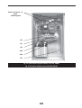
1
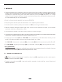
FUENTE DE ALIMENTACIÓN CONMUTADA FAC serie M SWITCH MODE POWER SUPPLY FAC M series. Manual de usuario, instalación y puesta en marcha. User’s Manual, Installation and Start-up. EK318H02 AVISOS DE SEGURIDAD SAFETY WARNINGS . .............................................................................................. 7 . .................................................................................................... 23 Manual de usuario, instalación y puesta en marcha...............................................5-19 User’s manual, installation and start up. ...............................................................21-35 -2- Les agradecemos de antemano, la confianza depositada en nosotros al adquirir este producto. Lean este manual de instrucciones cuidadosamente antes de poner en marcha el equipo y guardenlo para futuras consultas que puedan surgir. Quedamos a su entera disposición para toda información suplementaria o consultas que deseen realizarnos. Atentamente les saluda. SALICRU Siguiendo nuestra política de constante evolución, nos reservamos el derecho de modificar las características total o parcialmente sin previo aviso. Queda prohibida la reproducción o cesión a terceros de este manual, sin previa autorización por escrito por parte de nuestra firma. We would liket to thank you in advance for the trust you have placed in us by purchasing this equipment. Read these instructions carefully before starting up the equipment and keep tehm for any possible future use. We remain at your entire disposal for any further information or any query you should wish to make. Thank you. SALICRU In our policy of constant evolution, we reserve the right to modify the characterisitcs in part or in whole without forewarning. All reproduction or third party concession of this manual is prohibited without the previous written authorisation of our company. -3- -4- Índice general. 1.-VISTAS DEL EQUIPO Y CONTROLES, (ver figuras 5 a 10). 2.-LEYENDAS CORRESPONDIENTES A LAS VISTAS DEL EQUIPO. 3.- AVISOS DE SEGURIDAD . 4.-DESCRIPCIÓN Y ESQUEMAS DE BLOQUES. 5.-NOMENCLATURA. 6.-RECEPCIÓN EQUIPO. 6.1.-Recepción y desembalaje. 6.2.-Almacenaje. 7.-INSTALACIÓN. 7.1.-Conexión a la red AC, bornes (C1). 7.2.-Conexión de las cargas a los bornes de salida DC (C4). 7.3.-Conexión del interface a relés (C6), FAC 165M. 7.4.-Conexión del interface a relés, (Opcional sólo para FAC 1000M). 7.4.1.-Interface a relés versión (I), en conector SUB-D9 (C6). 7.4.2.-Interface a relés versión (I3), en conector SUB-D9 (C6), aislamiento 3 kV. 8.-PUESTA EN MARCHA Y PARO. 8.1.-Puesta en marcha, FAC 165M. 8.2.-Puesta en marcha, FAC 1000M. 8.3.-Paro de la FAC 165M. 8.4.-Paro de la FAC 1000M. 9.-INDICACIONES Y SINÓPTICO. 9.1.-Indicaciones para FAC 165M. 9.2.-Sinóptico para FAC 1000M. 9.2.1.-Indicaciones ópticas. 10.-CARACTERÍSTICAS TÉCNICAS. 10.1.-Características FAC 165M. 10.2.-Características FAC 1000M. -5- 1.- VISTAS DEL EQUIPO Y CONTROLES, (ver figuras 5 a 10). 2.- LEYENDAS CORRESPONDIENTES A LAS VISTAS DEL EQUIPO. Elementos de conexión: (C1) Bornes alimentación de entrada AC. (C4) Bornes de salida DC. (C5) Borne toma de tierra ( ). (C6) Conector o bornes interface a relés. Elementos de protección y maniobra: (M0) Interruptor marcha-paro con lámpara de indicación incorporada «equipo en marcha». (M1) Seccionador con fusible o interruptor magnetotérmico de entrada. (M2) Seccionador con fusible o interruptor magnetotérmico de baterías. Panel de controI, indicaciones ópticas FAC 165M: (x) Neón «Input» (Red presente). (y) Led «Rectifier failure» (Fallo rectificador). (z) Led «Mains failure» (Fallo de red). Panel de controI, indicaciones ópticas FAC 1000M: (a) Led «Marcha». (b) Led «Alarma». (c) Led «Tensión flotación». (d) Led «Descarga». Panel de controI, visualizador y teclado (únicamente en sinóptico con display LCD): (e) Display. (f) Tecla «ON» en sinópticos a leds o «ENT/ON» en sinópticos con display LCD. (g) Tecla «OFF» en sinópticos a leds o «ESC/OFF» en sinópticos con display LCD. (h) Tecla cursor de avance « ». (i) Tecla cursos de retroceso « ». (j) Tecla cursor desplazamiento hacia la derecha « ». (k) Tecla cursor desplazamiento hacia la izquierda « ». Abreviaciones y elementos varios: (Cl) Cierre-tirador puerta frontal. (Pa) Puerta frontal caja metálica. -6- 3.- AVISOS DE SEGURIDAD . • Junto con el equipo y el "Manual de instrucciones" del mismo, se suministra la información relativa a las «Instrucciones de seguridad» (Ver documento EK266*08). Antes de proceder a la instalación o puesta en marcha, comprobar que dispone de ambas informaciones, de lo contrario solicítelas. Es obligatorio el cumplimiento relativo a las "Instrucciones de seguridad", siendo legalmente responsable el usuario en cuanto a su observancia. Una vez leídas, guárdelas para futuras consultas que puedan surgir. AVISOS DE SEGURIDAD PARTICULARES. El producto FAC descrito en este Manual de Uso, fue diseñado, fabricado y comercializado de acuerdo con la norma EN ISO 9001 de Aseguramiento de la Calidad. El marcado CE indica la conformidad a las Directivas de la CEE ( que se citan entre paréntesis) mediante la aplicación de las normas siguientes: • EN 61204: Dispositivos de alimentación de baja tensión, con salida de corriente continua Características de funcionamiento y requerimientos de seguridad. (Directiva Baja Tensión 73/23/CEE). • EN 41003: Requerimientos particulares de seguridad para equipos conectables a líneas de telecomunicación. (Directiva de Baja Tensión 73/23/CEE). • IEC 1204-3: Dispositivos de alimentación de baja tensión, con salida de corriente continua. Norma de producto de C.E.M. (Directiva de Compatibilidad Electromagnética 89/336/CEE). Cuando se utilice como componente un FAC para una instalación compleja o sistema, deberán aplicarse las Normas Genéricas o de Producto correspondientes a esta instalación o sistema específicos. Es posible que al añadir elementos, o al estar sujeto a los requerimientos de una normativa determinada, el conjunto deba someterse a correcciones para asegurar la conformidad a las Directivas europeas y correspondiente legislación nacional. Es responsabilidad del Proyectista y/o Instalador, el cumplimiento de la normativa, dotando a la instalación de los elementos correctores necesarios para ello. Según las condiciones de instalación del equipo cargador-baterías deberán adoptarse o no las correcciones detalladas más abajo en el apartado Compatibilidad Electromagnética. Además, para todas las variantes y en lo referente a la Seguridad (normas EN 61204 y EN41003), deben tenerse en cuenta los siguientes aspectos de Producto: SEGURIDAD DE B.T.: • La FAC es un equipo eléctrico con protección Clase l. Es imprescindible la conexión de la toma de tierra de protección al borne correspondiente para asegurar la protección contra choques eléctricos. La toma de tierra de protección debe ser independiente de la Red de Telecomunicación, (la cual puede estar conectada a la salida de la fuente). • La conexión a tierra está garantizada aunque se disparen las protecciones de entrada. • Las distancias de aislamientos se han previsto para una polución con un Grado de Contaminación 2 (P2), de acuerdo con la norma HD 625.1. S1 (IEC 664-1mod.): Contaminación no conductora, excepto temporalmente cuando se produce condensación ocasional. Para ambientes muy contaminados (con partículas conductoras) o con condensación de la humedad frecuente, deberán preverse protecciones adicionales. • El equipo posee un dispositivo de protección térmico para la protección de los semiconductores de potencia. Este dispositivo interrumpe el funcionamiento a partir de una temperatura determinada; al enfriarse la fuente se restablece el suministro. Compruébese que esta función no represente peligro alguno al aparecer de improviso la tensión. (Sólo en FAC 1000M). -7- • El nivel de seguridad del circuito de salida de una FAC es de un Circuito de Tensión de Red de Telecomunicación. Es decir, que la salida posee las características de aislamiento requeridas para poderse conectar a una Red de Telecomunicación, de acuerdo con la norma citada EN 41003. Debe cuidarse que el resto de la instalación conectada a esta salida cumpla también estos requisitos. COMPATIBILIDAD ELECTROMAGNÉTICA (C.E.M).: En cuanto a la C.E.M., y especialmente en lo referente a emisiones conducidas o radiadas, la alimentación y el conexionado exteriores a la FAC serán decisivos para el cumplimiento de los requerimientos exigidos por la normativa. Debe procurarse emplear conexiones cortas, desacoplando al máximo las líneas de entrada de las de salida. La toma de tierra puede ser un punto conflictivo en el caso de presentar una impedancia excesiva a las radiofrecuencias. Deberán tenerse en cuenta las siguientes reglas de instalación: (*) • A la entrada: Por lo general será necesario instalar el Filtro de Entrada de nuestra firma, en especial con líneas de impedancia elevada. En el caso en que se prescinda de este filtro, deberá comprobarse: Que la radiación se mantiene dentro de los límites exigidos por la normativa. Que los aparatos instalados en las inmediaciones de la fuente, alimentados por dicha línea, son inmunes a las emisiones de la misma. • A la salida: Por lo general será necesaria la instalación del Filtro de Salida previsto por nuestra firma, a no ser que la línea de salida quede confinada dentro de un armario metálico común con las cargas y batería de acumuladores, o que dicha línea esté cuidadosamente apantallada. Si no se instala el filtro, deberá comprobarse: Que la radiación se mantiene dentro de los límites exigidos por la normativa. Que los aparatos alimentados por la fuente son inmunes a las emisiones del mismo. Resumiendo: Los filtros indicados como Filtro de Entrada y Filtro de Salida, son los que nuestra firma ha desarrollado para el cumplimiento de la Directiva de C.E.M. 89/336/CEE y que permiten el marcado CE del producto. Cuando en la instalación se prescinde de ellos, es reponsabilidad del Proyectista, del Instalador o de ambos, el substituirlos por disposiciones u otros componenetes que hagan que el conjunto de la instalación cumpla con las exigencias de la Directiva de C.E.M. (*) A excepto de la FAC 165M en que normalmente no será necesario instalar el Filtro ni de Entrada ni de Salida. -8- 4.- DESCRIPCIÓN Y ESQUEMAS DE BLOQUES. Fuente aliment. entrada Control DC/DC Monitor programador Baterías Fig. 1.1. Esquema de bloques FAC 165M. Conversor DC/DC Rectificador Filtro salida SALIDA DC Conversor AC/DC ENTRADA AC Trafo adaptador tensión SALIDA DC ENTRADA AC Filtro entrada Rectificador Fuente aliment. salida Interrup. estático Control micro Baterías Fig. 1.2. Esquema de bloques FAC 1000M. El principio de funcionamiento consiste en la transformación de la tensión alterna de entrada, previamente acondicionada mediante un filtro de línea, a una tensión continua una vez transformada, rectificada y controlada. Un relé o interruptor estático según modelo, situado a la salida de la FAC, es el responsable de desconectar las baterías cuando se alcanza la tensión mínima de descarga, en aquellas fuentes que dispongan de autonomía. Digitalmente se controlan las constantes vitales de la fuente a través de un microprocesador, que además, es el encargado de gestionar los ajustes y medidas visualizables, si incorpora sinóptico con el display LCD. -9- 5.- NOMENCLATURA. Nomenclatura FAC 165M. Siglas abreviatura «Fuente Alimentación Conmutada». Tipo. Serie de la FAC. Tensión entrada AC. Tensión salida DC. Si se conecta a masa el positivo o negativo, se indicará según ejemplo: (-48) o (+48), respectivamente. FAC M/ - - A ´ Autonomía en minutos. Intensidad de salida. (*) La FAC 165 M suministra el interface a relés de serie con las señales: «Fallo cargador» y «Fallo de red». Nomenclatura FAC 1000M. Siglas abreviatura «Fuente Alimentación Conmutada». Tipo. Serie de la FAC. Interface a relés opcionales: I (estándar) o I3 (con aislamiento de 3kV). Sinóptico: D (con display LCD), opcional. Sin indicación a leds. Alarma fallo aislamiento opcional: F. Sólo es posible en equipos con salida flotante (sin conexión de positivo o negativo a masa) y a condición de que incorpore el sinóptico con display LCD opcional. FAC M-••• / - - A ´ Comprobar que las cargas conectadas a la FAC, no dispongan de conexión entre uno de los polos de salida y la masa, antes de empezar la operatoria de instalación. Autonomía en minutos. Intensidad de salida. Tensión salida DC. Si se conecta a masa el positivo o negativo, se indicará según ejemplo: (-48) o (+48), respectivamente. Tensión entrada AC. - 10 - 6.- RECEPCIÓN EQUIPO. 6.1.- Recepción y desembalaje. • Al recepcionar el equipo, verificar que no ha sufrido ningún percance durante el trasporte. En caso contrario realizar las oportunas reclamaciones a su proveedor o en su falta a nuestra firma. Igualmente verificar que los datos de la placa de características pegada en la parte interior de la puerta frontal, corresponden a las especificadas del pedido, para ello será necesario desembalarlo. De no ser así, cursar la disconformidad a la mayor brevedad posible, citando el nº de fabricación del equipo y las referencias del albarán de entrega. • Una vez realizada la recepción, es conveniente embalar de nuevo la FAC hasta su puesta en servicio con la finalidad de protegerlo contra posibles choques mecánicos, polvo, suciedad, etc... • El embalaje del equipo consta de palet de madera, envolvente de cartón o madera según casos, cantoneras de EPS o PE, funda y fleje de PE, todos, materiales reciclables; por lo que si se va a desprender de ellos, deberá hacerse de acuerdo a las leyes vigentes. Recomendamos guardar el embalaje por si se tuviera que utilizar en el futuro. 6.2.- Almacenaje. • El almacenaje del equipo, se hará en un local seco, ventilado y al abrigo de la lluvia, proyecciones de agua o agentes químicos. Es aconsejable mantener el equipo en su embalaje original ya que ha sido específicamente diseñado para asegurar al máximo, la protección durante el transporte y almacenaje. • Las FAC incorporan baterías herméticas de plomo-calcio o de niquel-cadmio, según especificaciones particulares del pedido, y su almacenaje no deberá de exceder de 6 meses (ver fecha recarga de baterías, indicada en el embalaje del equipo). Transcurrido este período cargar las baterías hasta alcanzar el nivel de flotación, momento en que esta indicación del sinóptico se activará. Ello implica la conexión del equipo a la red comercial y su puesta en marcha, leer los respectivos capítulos. Posteriormente volver a guardar la FAC en su embalaje original, anotando la nueva fecha de recarga de las baterías en la respectiva etiqueta. No almacenar los aparatos en donde la temperatura ambiente exceda de 40º C o descienda de –20º C, ya que lo contrario puede revertir en la degradación de las características eléctricas de las baterías. - 11 - 7.- INSTALACIÓN. • El equipo está diseñado como un elemento mural para ser fijado a la pared. Fijarlo a través de los taladros previstos en la parte posterior. Para ello es necesario abrir la puerta frontal, presionar sobre la parte más alta del cierre-tirador (Cl), éste quedará perpendicular a la puerta del equipo, girarlo 90º en sentido antihorario y abrir la puerta (Pa) (ver figuras 5, 7a ó 7b según modelo). Si el cierre del equipo se encuentra bloqueado a través del mecanismo interior, desbloquearlo previamente mediante la llave suministrada junto con la documentación. • Revisar las "Instrucciones de seguridad" (ver documento EK266*08). • Comprobar que los datos de la placa de características son los requeridos para la instalación. • Una mala conexión o maniobra, puede provocar averías en la FAC y/o en las cargas conectadas a ésta. • Todas las conexiones del equipo incluidas las de control, se harán con los interruptores en reposo y sin red presente (seccionador de la línea de alimentación en «Off»). • Las conexiones se realizarán a través de los bornes previstos en el interior del equipo. • Las secciones de los cables de entrada, salida y toma de tierra estarán en consonancia con la corriente nominal de la placa de características, respetando el Reglamento Electrotécnico de Baja Tensión local. • Comprobar que el seccionador (M1) de la FAC 165M esté en posición «On» y con el fusible interno colocado y en buen estado. En caso de estar fundido, sustituir por uno del mismo tamaño, tipo y calibre. •En la FAC 165M, el interruptor de marcha-paro (M0) y el seccionador (M2) deberán de encontrarse en posición «O» u «Off». . • En la FAC 1000M, comprobar que el interruptor (M1) y el seccionador o interruptor (M2), estén en posición «O» u «Off». • MUY IMPORTANTE: Si la FAC no va ser utilizada durante un período de tiempo superior al mes, asegurarse de que el seccionador o interruptor magnetotérmico de baterías (M2) esté desactivado (posición «O» u «Off»). 7.1.- Conexión a la red AC, bornes (C1). • Deberá conectarse obligatoriamente la conexión a tierra, borne (C5), asegurándose que ello se realiza antes de conectar la tensión a la entrada de la FAC. • Conectar los bornes de entrada (C1) sin que exista tensión, respetando el orden de la fase y neutro indicado en el etiquetado del equipo. - 12 - 7.2.- Conexión de las cargas a los bornes de salida DC (C4). Deberá conectarse obligatoriamente a tierra todas las cargas conectadas a los bornes de salida de la FAC, utilizando • para ello el borne (C5). • Conectar las cargas críticas a los bornes de salida (C4), respetando el color de los cables (rojo para positivo y negro para negativo), y la polaridad indicada en el etiquetado del equipo. 7.3.- Conexión del interface a relés (C6), FAC 165M. • El interface a relés hace posible un diálogo entre el equipo y el mundo exterior. Se dispone mediante los contactos conmutados de dos relés de la información de: Fallo de cargador, Fallo de red (ver figura 2b). • La línea de comunicaciones (interface) constituye un circuito de muy baja tensión de seguridad. Para conservar su cualidad debe instalarse separada de otras líneas que lleven tensiones peligrosas (líneas de distribución de energía). Borne Borne Borne Borne Borne Borne 31. Contacto normalmente abierto relé «Fallo rectificador». 32. Contacto normalmente cerrado relé «Fallo rectificador». 33. Contacto común relé «Fallo rectificador». 34. Contacto normalmente abierto relé «Fallo de red». 35. Contacto normalmente cerrado relé «Fallo de red». 36. Contacto común relé «Fallo de red». Considerar que la corriente y tensión máxima aplicable a los contactos a relés es de 1A 250V AC. • Los contactos a relés son normalmente abiertos, cerrándose al provocarse la alarma. • Una vez realizada la conexión del equipo cerrar la puerta frontal (Pa), bloqueándola mediante la llave suministrada. 7.4.- Conexión del interface a relés, (Opcional sólo para FAC 1000M). • Debe considerarse que opcionalmente se dispone de dos tipos de interface a relés, siendo excluyentes mútuamente. 7.4.1.- Interface a relés versión (I), en conector SUB-D9 (C6). • La línea de comunicaciones (interface) constituye un circuito de muy baja tensión de seguridad. Para conservar su cualidad instalarse separada de otras líneas que lleven tensiones peligrosas (líneas de distribución de energía). Considerar que la corriente y tensión máxima aplicable a los contactos a relés es de 2A 30V DC ó 0,6A 125V AC. - 13 - • El interface a relés hace posible un diálogo entre la FAC y el mundo exterior. Mediante los contactos de los 5 relés del interface (Ra..Re), es posible suministrar a través del conector SUB-D9 (C6) un máximo de 5 eventos diferentes del equipo, uno a cada pin. Estos eventos (alarmas o estados del equipo) pueden ser programados a criterio del usuario, en el caso de que disponga de sinóptico con LCD, a unos determinados pins del conector SUB-D9 (C6), a través del teclado del mismo (ver apartados 1.2 y 1.3 del Manual de Instrucciones EK331*05). Por defecto de fábrica, se les ha asignado los siguientes: Pin 1.Pin 2.Pin 3.Pin 4.Pin 5.Pin 6.Pin 7.Pin 9.- (Rc) Paro por final de autonomía (Alarma final de autonomía). (Rb) Alarma batería baja (Tensión mínima de utilización). (Ra) Batería en descarga. (Re) Fallo rectificador. (Rd) Fallo línea de entrada. Positivo (+) Shutdown. Negativo (-) Shutdown. Común relés. • Los contactos a relés son normalmente abiertos, cerrándose al provocarse la alarma. En el mismo conector se encuentra disponible una entrada de «Shutdown» que permite apagar el sistema cuando por ella tenemos una tensión de entre 8 y 15V (15mA). 1 6 5 9 Fig. 2. Conector SUB-D9 (C6). 7.4.2.- Interface a relés versión (I3), en conector SUB-D9 (C6), aislamiento 3 kV. • La línea de comunicaciones (interface) constituye un circuito de muy baja tensión de seguridad. Para conservar su cualidad debe instalarse separada de otras líneas que lleven tensiones peligrosas (líneas de distribución de energía). Considerar que la corriente y tensión máxima aplicable a los contactos a relés es de 2A 30V DC ó 0,6A 125V AC. • El interface a relés hace posible un diálogo entre la FAC y el mundo exterior. Mediante los contactos de los 2 relés del interface (Ra y Rb), es posible suministrar a través del conector SUB-D9 (C6) un máximo de 2 eventos diferentes del equipo. Esto eventos (alarmas o estados del equipo) pueden ser programados a criterio del usuario, en el caso de que disponga de sinóptico con LCD, a los pins 1 ó 3 del conector SUB-D9 (C6), a través del teclado del mismo (ver apartados 1.2 y 1.3 del Manual de Instrucciones EK331*05). Por defecto de fábrica, se les ha asignado los siguientes: Pin 2.- (Rb) Alarma batería baja (Tensión mínima de utilización). Pin 3.- (Ra) Batería en descarga. Pin 9.- Común relés. • Los contactos a relés son normalmente abiertos, cerrándose al provocarse la alarma. 1 6 5 9 Fig. 3. Conector SUB-D9 (C6). - 14 - 8.- PUESTA EN MARCHA Y PARO. • Verificar que se ha respetado lo indicado en el capítulo 7 de Instalación. • Con las cargas en reposo, aplicar tensión de red comercial a los bornes de entrada (C1). • Si la protección de baterías (M2) es un seccionador, colocar el fusible suministrado con la documentación del equipo, en éste. En caso de fusión, sustituir por uno del mismo tamaño, tipo y calibre. 8.1.- Puesta en marcha, FAC 165M. • Colocar el interruptor de marcha-paro (M0) a posición «I», la lámpara del interruptor se activará indicando «equipo en marcha». • Accionar el seccionador (M2) de baterías a posición «I» u «On».. • Poner en marcha la carga o cargas conectadas al equipo. 8.2.- Puesta en marcha, FAC 1000M. • Accionar el interruptor (M1) y el seccionador o interruptor (M2) a posición «I» u «On», las leds (b) y (d) se activarán en señal de alarma y descarga de baterías respectivamente, debido al consumo interno de la electrónica. • En los equipos con sinóptico a leds, pulsar dos veces consecutivas la tecla (f), el equipo se pondrá en marcha y consecuentemente se activará la led (a) y se apagarán las leds (b) y (d). Además, si las baterías se encuentrán en flotación se activará la led (c). Para mayor información sobre las indicaciones ópticas del sinóptico, ver capítulo 9. • Si incorpora sinóptico con display LCD, seguir los pasos guiados de la figura 4.1 y el equipo se pondrá en marcha. Los leds del sinóptico se activarán o desactivarán de acuerdo al estado del equipo. Para mayor información sobre las indicaciones ópticas del sinóptico, ver capítulo 9. • Poner en marcha la carga o cargas conectadas al equipo. MONITOR FAC OFF PONER EN MARCHA (ENTER) MONITOR FAC ON Si no se desea poner en marcha la FAC. Nota: La tecla ON y ENT físicamente es un mismo elemento, y aparece en la serigrafía del sinóptico como ENT/ON. El hecho de que en esta figura se indiquen como elementos distintos, no tiene otra finalidad que la de indicar la función correspondiente a la acción a realizar. Fig. 4.1. Puesta en marcha si incorpora el equipo display LCD. - 15 - 8.3.- Paro de la FAC 165M. • Parar la carga o cargas conectadas al equipo. • Accionar el interruptor (M1) y el seccionador (M2) a posición «O» u «Off», el equipo quedará fuera de servicio. • Colocar el interruptor de marcha-paro (M0) a posición «O», la lámpara del interruptor «equipo en marcha», se apagará. El equipo quedará fuera de servicio. • Atención: Después de un shutdown por final de autonomía, al retornar la red el equipo se pone en marcha de forma automática. 8.4.- Paro de la FAC 1000M. • Parar la carga o cargas conectadas al equipo. • Pulsar dos consecutivas sobre la tecla (g), considerando que en la segunda pulsación debe mantenerse presionada la tecla durante aprox. 10 segundos. El equipo dejará de suministrar tensión de salida, se apagará el led (a), y se activarán los leds (b) y (d) en señal de alarma y descarga de baterías respectivamente, debido al consumo interno de la electrónica. • Si incorpora sinóptico con display LCD, seguir los pasos establecidos en al figura 4.2 y el equipo se parará. Pulsar dos veces consecutivas la tecla (g), se debe tener en cuenta que en la segunda pulsación debe mantenerse presionada la tecla entre 5 y 6 segundos. Los leds de alarma (b) y descarga (d) permanecerán activos, debido al consumo interno de la electrónica. • Accionar las protecciones (M1) y (M2) a posición «O» u «Off», las leds (b) y (d) se desactivarán. El equipo quedará fuera de servicio. Importante: Debido al consumo propio del sinóptico las baterías tienen una pequeña descarga, por lo que se debe realizar un paro completo si el equipo no va ser utilizado durante los próximos 30 días. MONITOR FAC ON PARAR (ESCAPE) presionar durante 10 seg. BATERIAS EN DESCARGA MONITOR FAC OFF Si no se desea parar la FAC. Nota: La tecla OFF y ESC físicamente es un mismo elemento, y aparece en la serigrafía del sinóptico como ESC/OFF. El hecho de que en esta figura se indiquen como elementos distintos, no tiene otra finalidad que la de indicar la función correspondiente a la acción a realizar. Fig. 4.2. Puesta en marcha si incorpora el equipo display LCD. • Atención: Si con el equipo en marcha se realiza un paro brusco directamente a través de las protecciones (M1) y (M2), sin realizar el proceso de paro descrito en este apartado, en el mismo instante en que se activen, la FAC suministrará tensión de salida sin ser necesario la activación del pulsador (g). Lo mismo sucede después de un shutdown por final de autonomía; al retornar la red el equipo se pone en marcha de forma automática. - 16 - 9.- INDICACIONES Y SINÓPTICO. 9.1.- Indicaciones para FAC 165M. Las indicaciones del frontal se iluminan cuando la alarma o estado en cuestión se activa. (M0)Neón de color verde incorporada en el interruptor marcha-paro. Activada indica «equipo en marcha». (x) Neón de color verde, activa indica «Red presente». (y) Neón de color rojo, activa indica «Fallo rectificador». Avisar al SAT (Servicio de Asistencia Técnica). (z) Neón de color rojo, activa indica «Fallo de red». Además el equipo incorpora una alarma acústica de final de autonomía. A partir del momento en que se active, quedarán aproximadamente 2 minutos para el «Final de autonomía» y por tanto dejará de suministrar tensión de salida. La alarma acústica cesa cuando la causa que la provoca desaparece. 9.2.- Sinóptico para FAC 1000M. • La FAC dispone de unas indicaciones ópticas y acústicas de única tonalidad, para ambos sinópticos. Cualquier anomalía activará simultáneamente la alarma acústica y óptica (led). En los equipos con sinóptico a leds, la alarma acústica cesa cuando la causa que la provoca desaparece. La identificación y reconocimiento de las alarmas activas en equipos con sinóptico LCD se realizará siguiendo los pasos descritos en el Manual de Instrucciones (EK331*05). No es posible identificar las alarmas en las FAC con sinóptico a leds, salvo la de «Baterías en Descarga» por la propia led (d) o indirectamente las programadas en el interface a relés si se dispone de este opcional. 9.2.1.- Indicaciones ópticas. (a) (b) (c) (d) Equipo en marcha, color verde. Alarma, color rojo Baterías cargadas en nivel de flotación, color verde. Baterías en descarga, sinónimo de fallo de red, color amarillo. - 17 - 10.- CARACTERÍSTICAS TÉCNICAS. 10.1.- Características FAC 165M. Entrada: Tensión ........................................................................................ 230 V AC ±15 %. Frecuencia ................................................................................... 50/60 Hz. Factor de potencia ....................................................................... 0,7. Rendimiento típico ....................................................................... >0,85. Protección.................................................................................... Fusible tubular 5x20 mm, F3A 250 V AC. Salida: Tensión nominal ........................................................................... 12, 24 ó 48 V DC. Intensidad .................................................................................... Hasta 3 A. Precisión (con baterías cargadas) ................................................ ±1 %. Nivel de rizado ............................................................................. < 200 mV pp. Baterías: Protección.................................................................................... Seccionador con fusible 38x10 mm, T32A 380 V AC. Tipo de carga ............................................................................... I/U. Intensidad de carga ..................................................................... 1 A. Protecciones ................................................................................ Sobretensión y subtensión. Tipo baterías ................................................................................ Pb-Ca u opcionalmente Ni-Cd. Interface a relés (opcional): Asignación ................................................................................... Fallo de red. Fallo rectificador. Número de relés .......................................................................... 2. Shutdown remoto ........................................................................ No. Generales: Estructura .................................................................................... Monofásica. Grado de protección según UNE 20 324 IR ................................. IP 21. Aislamiento ................................................................................. > 10 MΩ. Ruido acústico a 1 metro ............................................................. < 40 dB. Ventilación ................................................................................... Natural. Temperatura de trabajo: .............................................................. 0 ºC a 40 ºC. Temperatura de almacenamiento: ............................................... -20 ºC a +80 ºC. Humedad relativa ........................................................................ Hasta 95 % no condensada. Altitud de trabajo ......................................................................... Hasta 2400 m s.n.m. MTBF ........................................................................................... 60.000 horas. MTTR ........................................................................................... 30 minutos. Conformidad a normas y calidad: Marcado CE, seguridad / EMC .................................................... EN 60950 / EN 61204-3. Certificación ................................................................................ ISO-9001. - 18 - 10.2.- Características FAC 1000M. Entrada: Tensión ........................................................................................ 230 V AC ±15 %. Frecuencia ................................................................................... 50/60 Hz. Factor de potencia ....................................................................... 0,99. Rendimiento típico ....................................................................... >0,90. Protección.................................................................................... Interruptor magnetotérmico. Salida: Tensión nominal ........................................................................... 12, 24, 48, 110 ó 125 V DC. Intensidad .................................................................................... Hasta 25 A. Precisión (con baterías cargadas) ................................................ ±0,1 %. Nivel de rizado ............................................................................. < 20 mV pp. Baterías: Protección.................................................................................... Interruptor magnetotérmico. Tipo de carga ............................................................................... I/U. Intensidad de carga ..................................................................... 0,1 C. Protecciones ................................................................................ Sobretensión y subtensión. Tipo baterías ................................................................................ Pb-Ca u opcionalmente Ni-Cd. Interface a relés o con aislamiento a 3 kV (opcional): Asignación ................................................................................... Programable en sinóptico con display LCD. Número de relés .......................................................................... Estandar 5. Con aislamiento a 3 kV, 2. Shutdown remoto ........................................................................ En interface a relés estandar, 12V 10mA. Generales: Estructura .................................................................................... Monofásica. Grado de protección según UNE 20 324 IR ................................. IP 21. Aislamiento ................................................................................. > 10 MΩ. Ruido acústico a 1 metro ............................................................. < 40 dB. Ventilación ................................................................................... Forzada. Temperatura de trabajo: .............................................................. 0 ºC a 40 ºC. Temperatura de almacenamiento: ............................................... -20 ºC a +80 ºC. Humedad relativa ........................................................................ Hasta 95 % no condensada. Altitud de trabajo ......................................................................... Hasta 2400 m s.n.m. MTBF ........................................................................................... 60.000 horas. MTTR ........................................................................................... 30 minutos. Conformidad a normas y calidad: Marcado CE, seguridad / EMC ..................................................... EN 60950 / EN 61204-3. Certificación ................................................................................. ISO-9001. - 19 - - 20 - General Index. 1.- VIEWS OF THE FAC (see figures 5 to 10). 2.- KEYS TO THE VIEWS OF FAC. 3.- SAFETY WARNINGS . 4.- DESCRIPTION AND BLOCK DIAGRAM. 5.- NOMENCLATURE. 6.- DEVICE RECEPTION. 6.1.- Reception and unpacking. 6.2.- Storage. 7.- INSTALLATION. 7.1.- Connecting to the AC mains, terminals (C1). 7.2.- Connecting the DC output terminals to the loads. 7.3.- Connecting the relay interface (C6), FAC 165 M. 7.4.- Connecting the relay interface, (Optional only for FAC 1000). 7.4.1.- Relay Interface version (I) in SUB-D9 connector (C6). 7.4.2.- Relay Interface version (I3) in SUB-D9 connector (C6), 3 kV isolation. 8.- STARTING UP AND SHUTTING DOWN. 8.1.- Starting up, FAC 165 M. 8.2.- Starting up FAC 1000 M. 8.3.- Shutting down, FAC 165 M. 8.4.- Shutting down FAC 1000 M. 9.- INDICATIONS AND SYNOPTIC. 9.1.- Indications for FAC 165 M. 9.2.- Synoptic for 1000 M 9.2.1.- Optical indications. 10.- COMMON TECHNICAL SPECIFICATIONS. 10.1.- FAC 165 M specifications. 10.2.- FAC 1000 M specifications. - 21 - 1.- VIEWS OF THE FAC (see figures 5 to 10). 2.- KEYS TO THE VIEWS OF FAC. Connection elements: (C1) AC Input terminals. (C4) DC output terminals. (C5) Ground terminal ( ). (C6) Connector or terminals relay interface. Protection and handling elements: (M0) Start-stop switch with built-in «device running» indication lamp. (M1) Cut-off switch with input fuse or MCB. (M2) Cut-off switch with battery fuse or MCB. Control panel, optical indications FAC 165 M: (x) Input neon (mains present) (y) Rectifier failure led (z) Mains failure led. Control panel, optical indications FAC 1000 M: (a) «Operating» led. (b) «Alarm» led. (c) «Float voltage» led. (d) «Discharge» led. Control panel, visualiser and keyboard (only in synoptic with LCD display): (e) Display. (f) «ON» key in led synoptics or «ENT/ON» with LCD display. (g) «OFF» key in synoptics to leds or «ESC/OFF» with LCD display. (h) Cursor forward key « ». (i) Cursor back key « ». (j) Cursor right key « ». (k) Cursor left key « ». Abbreviations and miscellaneous elements: (Cl) Front door handle-close (Pa) Front door metal box - 22 - 3.- SAFETY WARNINGS . • The equipment and its «User’s manual» are accompanied by information concerning the «Safety Instructions» (See document EK266*08). Before proceeding with the installation or start up, make sure that you have both sets of information and if not, please ask for them. Compliance with the «Safety Instruction» is obligatory, observance of this being legally the user’s responsibility. Having read the safety instructions, keep them in a safe place for future reference. PARTICULAR SAFETY WARNINGS. The FAC product described herein was designed, manufactured and commercialised in accordance with EN ISO 9001 standard Quality Assurance. The CE marking indicates conformity with the directives of the EEC (quoted between brackets) by means of the application of the following standards: • EN 61204: Low voltage supply apparatuses, with direct current output. Operating specifications and safety requirements (Low Voltage Directive 73/23/CEE). • EN 41003: Particular safety requirements for devices that can be connected to telecommunication networks (Low Voltage Directive 73/23/CEE). • IEC 1204-3: Low voltage supply devices, with direct current output. C.E.M. product regulation (Electromagnetic Compatibility Directive 89/336/CEE). When a FAC is used as a component in a complex or system installation, the Generic Standards or Product standards corresponding to this specific installation or system must be applied. It is possible that when elements are added or as it is subject to the requirements of a certain standard, the device might require corrections to assure conformity with European directives and corresponding national legislation. It is the responsibility of the Projector and/or Installer to comply with the standard, by providing the installation with all necessary corrective elements. Depending on the battery charger installation conditions, the corrections described below in the aside Electromagnetic Compatibility will or will not be adopted. Furthermore, for variations and as regards Safety (standards EN 61204 and 41003), the following Product aspects must be taken into account: L.V. SAFETY: • The FAC is an electrical device with Class I protection. It must be connected to the corresponding ground protection terminal to ensure protection against electric shocks. The protection ground socket must be independent of the Telecommunications Network (which may be connected to the source output). • The ground connection is assured even though the input protections might be triggered. • The insulation distances have been provided for pollution of Contamination Grade 2 (P2), in accordance with HD 625.1. S1 (IEC 664-1 mod.): non conductive contamination, except for temporarily when occasional condensation is caused. Additional protection must be provided for highly contaminated environments (with conductive particles) or frequent condensation. • The device has thermal protection for protecting the power semiconductors, which stops the operation from a certain temperature; when cool, the source restores the power supply. Make sure that this function is not dangerous when the voltage returns unexpectedly (only in FAC 1000 M). - 23 - • The safety level of the output circuit of a FAC is a Telecommunications Network Voltage Circuit, that is, the output has the same insulation characteristics required to be able to connect to a Telecommunications Network according to the referred EN 41003. It must be ensured that the rest of the installation connected to this output also fulfils these requirements. ELECTROMAGNETIC COMPATIBILITY (E.M.C.): As regards the E.M.C., and particularly conducted or radiated emissions, the supply and exterior connections to the FAC will be decisive for fulfilling the requirements demanded by the standard. It must be attempted to use short connections, separating as far as possible the input lines from the output. The ground may be a conflictive point if it presents excessive impedance to radio frequencies. The following installation rules must be borne in mind: (*) • On the input: It will generally be necessary to install our firm’s Input Filter, particularly with high impedance lines. Should this filter not be used, it must be ensured: That the radiation remains within the limits demanded by the regulations. That the devices installed around the source and supplied by the said line are immune to its emissions. • On the output: It will generally be necessary to install our firm’s Output Filter, unless the output line is confined in a common metal cabinet with the charges and set of accumulators, or that the line is carefully screened. If the filter is not installed, it must be ensured: That the radiation remains within the limits demanded by the regulations. That the devices supplied by the power supply are immune to its emissions. Summing up: The filters indicated as Input Filter and Output Filter are those that our firm has developed in order to comply with the E.M.C. Directive 89/336/CEE and which allow the product to be CE marked. When they are not used in an installation, it is the responsibility of the Projector, the Installer or both of these to replace them with layouts or other components that enable the installation to comply with the requirements of the E.M.C. Directive. (*) Except for the FAC 165 M, where normally it is not necessary to install the Input or Output filter. - 24 - 4.- DESCRIPTION AND BLOCK DIAGRAM. Power supply input DC/DC Control Programmer monitor Batteries Fig. 1.1. FAC 165 M Block Diagram. DC/AC Converter Rectifier Output Filter AC OUTPUT DC/DC Converter Rectifier AC INPUT Voltage adapter trafo DC OUTPUT AC INPUT Input filter Power supply output Static switch Micro control Batteries Fig. 1.2. FAC 1000 M Block Diagram. The working principle consists of transforming the input alternating voltage previously conditioned by a line filter into direct voltage once transformed, rectified and controlled. A relay or static switch, depending on the model, on the FAC output, is responsible for turning off the batteries when the minimum discharge is reached, in power supplies with autonomy. The vital constants of the power supply are controlled digitally through a microprocessor, which is also responsible for managing the adjustments and measurements that can be visualised if the device has a synoptic with an LCD display. - 25 - 5.- NOMENCLATURE. FAC 165 M nomenclature. Abbreviation «Switch mode power supply». Type (box size: 1000, 2000, 4000, 6000 or 8000). FAC series. AC input voltage. DC output voltage. If the positive or negative is connected to ground, it will be indicated as in the example: (-48) or (+48), respectively. FAC M/ - - A ´ Autonomy in minutes. Output current. (*) The FAC 165 M supplies the standard relay interface with the «Charger failure» and «Mains failure» signals. FAC 1000 M nomenclature. Abbreviation «Switch mode power supply». Type FAC series. Optional relay interfaces: I (standard) or I3 (3 kV isolation) Synoptic: D (with LCD display), optional. No led indication. Optional isolation failure alarm: F. Only possible in devices with a floating output (without positive or negative connection to ground) and if it includes the optional LCD display. FAC M-••• / - - A ´ Make sure that the loads connected to the FAC make no connection between one of the output poles and the ground before beginning the installation procedure. Autonomy in minutes. Output current. DC output voltage. If the positive or negative is connected to ground, it will be indicated as in the example: (-48) or (+48), respectively. AC input voltage. - 26 - 6.- DEVICE RECEPTION. 6.1.- Reception and unpacking. • On receiving the device, make sure that it has not been damaged in any way during transport. Otherwise, make all suitable claims to your supplier or, short of this, to our firm. Also make sure that the data on the characteristics plate adhered to the rear of the unit, the side or the upper cover, depending on the model, correspond to those specified on the order, and to do this it will be necessary to unpack the device. If they fail to correspond, send your disconformity as soon as possible, referring to the manufacturing number of the unit and the delivery remittance references. • Having completed the reception, it is best to pack the FAC once more until it is put into service in order to protect it against possible mechanical knocks, dust, dirt, etc... • The packing consists of a wooden palette, cardboard surround or wood, depending on the case, EPS or PE edge protectors, PE sleeve and bands, all recyclable materials; therefore, if they are to be thrown away, they must be disposed of in accordance with applicable law. It is best to keep the packing in case it has to be used in the future. 6.2.- Storage. • The unit must be stored in a dry premises, well-ventilated and protected from the rain, water projections or chemical agents. It is best to keep the unit in its original packing as this packing has been specifically designed to ensure maximum protection during transport and storage. • The FAC have sealed lead-calcium or nickel-cadmium batteries, according to the specifications of the order, and must not be stored for more than 6 months (see battery recharging date indicated on the packing). After this time, charge the batteries to float level; when the level is reached, the indication on the synoptic will be activated. This means connecting the unit to the commercial mains and starting it up; read the respective chapters. Then put the FAC back in its original packing, noting the new battery charge date on the respective label. Do not store apparatuses where the ambient temperature exceeds 40º C or falls below -20º C, as otherwise the electrical characteristics of the batteries might be affected. - 27 - 7.- INSTALLATION. • This device is designed as a wall unit to be fixed to a wall. Fix it with the drill holes provided in the rear. To do this, open the front door, press on the top of the close-handle (Cl), perpendicular to the device door, turn it 90º anticlockwise and open the door (Pa) (see figures 5, 7a or 7b depending on the model). If the device close is locked with an internal mechanism, release it first with the key provided with the documentation. • Review the Safety Instructions (see document EK266*08). • Check that the data on the characteristics plate are those required for the installation. • A bad connection or manoeuvre may cause damage to the FAC and/or the loads connected to it. • All connections, including control, must be performed with the switches turned off and without any mains present (supply line cut-off switch «off»). • Connections will be carried out with the junctions provided inside the unit. • The cross sections of the input, output and ground wires will be in line with the nominal current on the characteristics plate, in full respect of the local Low Voltage Electro technical Regulation. • Make sure that the cut-off switch (M1) of the FAC 165 M is «On», with the internal fuse in place and in a good state. If the fuse has blown, replace it with another of the same size, type and calibre. • In the FAC 165 M, the start-stop switch (M0) and the cut-off switch (M2) must be «O» or «On». • In the FAC 1000 M, ensure that the switch (M1) and the cut-off switch (M2) must be «O» or «On». • VERY IMPORTANT: If the FAC is not going to be used for a period of time of more than one month, make sure that the cut-off switch or battery MCB (M2) is turned off («O» or «Off») 7.1.- Connecting to the AC mains, terminals (C1). • The ground connection, terminal (C5) must necessarily be connected before power is applied to the input of the FAC. • Connect the input terminals (C1) without voltage present, respecting the order of phase and neutral indicated on the device labelling. - 28 - 7.2.- Connecting the DC output terminals to the loads. • All the loads connected to the output of the FAC must necessarily be connected to ground with terminal (C5). • Connect the critical loads to the output terminals (C4), respecting the colour of the wires (red for positive, black for negative and green-yellow for ground), as well as the polarity indicated on the label of the device. 7.3.- Connecting the relay interface (C6), FAC 165 M. • The relay interface enables dialogue between the device and the outside world. Using the switched contacts of the two relays , we have information on: Charger failure, Main failure (see figure 2b). • The communications line (interface) is a circuit of very low safety voltage. To preserve its quality, it should be installed separate from other lines that carry dangerous voltages (power distribution lines). Terminal Terminal Terminal Terminal Terminal Terminal 31. Contact normally open, «Rectifier failure» relay. 32. Contact normally closed, «Rectifier failure» relay. 33. Relay common contact, «Rectifier failure». 34. Contact normally open, «Mains failure» relay. 35. Contact normally closed, «Mains failure» relay. 36. Relay common contact, «Mains failure». Consider that the maximum current and voltage applicable to the relay contacts are 1 A 250 V AC. • The contacts to relays are normally open, and close when the alarm is caused. • Having connected the device, close the front door (Pa) and lock it with the key supplied. 7.4.- Connecting the relay interface, (Optional only for FAC 1000). • It must be considered that two types of relay interface are available as options, and are mutually excluding. 7.4.1.- Relay Interface version (I) in SUB-D9 connector (C6). • The communications line (interface) is a circuit of very low safety voltage. To preserve its quality, it should be installed separate from other lines that carry dangerous voltages (power distribution lines). It is also necessary to consider the maximum current and voltage applicable to the SUB-D9 connector, 2 A 30 V DC or 0.6 A 125 V AC. - 29 - • The relay interface enables dialogue between the FAC and the outside world. Using the contacts of the 5 relays of the interface (Ra..Re), it is possible to supply a maximum 5 different events though the SUB-D9 connector (C6), one to each pin. These events (alarms or device states) may be programmed on the criteria of the user, should they have a synoptic with LCD, to certain pins of the SUB-D9 connector (C6), through the keyboard (see sections 1.2. and 1.3. of the Operating manual EK331*05). By default from factory, the following have been assigned: Pin 1.Pin 2.Pin 3.Pin 4.Pin 5.Pin 6.Pin 7.Pin 9.- (Rc) Shutdown end of back up time (End of autonomy alarm). (Rb) Low battery alarm (Minimum use voltage). (Ra) Batteries discharging. (Re) Rectifier fault. (Rd) Input line fault. Positive (+) Shutdown. Negative (-) Shutdown. Relay common. 1 5 6 • The contacts to relays are normally open and are closed when the alarm is caused. The same connector has a «Shutdown» entry that enables the system to be shut down when we have a voltage of between 8 and 15 V (15mA). 9 Fig. 2. SUB-D9 Connector (C6) 7.4.2.- Relay Interface version (I3) in SUB-D9 connector (C6), 3 kV isolation. • The communications line (interface) is a circuit of very low safety voltage. To preserve its quality, it should be installed separate from other lines that carry dangerous voltages (power distribution lines). It is also necessary to consider the maximum current and voltage applicable to the SUB-D9 connector, 2 A 30 V DC or 0.6 A 125 V AC. • The relay interface enables dialogue between the FAC and the outside world. Using the contacts of the 2 relays of the interface (Ra and Rb), it is possible to supply a maximum 2 different events though the SUB-D9 connector (C6). These events (alarms or device states) may be programmed on the criteria of the user, should they have a synoptic with LCD, to pins 1 or 3 of the SUB-D9 connector (C6), through the keyboard (see sections 1.2. and 1.3. of the Operating manual EK331*05). By default from factory, the following have 1 5 been assigned: Pin 2.- (Rb) Low battery alarm (Minimum use voltage). Pin 3.- (Ra) Batteries discharging. Pin 9.- Relay common. 6 • The contacts to relays are normally open and are closed when the alarm is caused. - 30 - 9 Fig. 3. SUB-D9 Connector (C6) 8.- STARTING UP AND SHUTTING DOWN. • Make sure that everything indicated in chapter 7 has been respected. • With the loads at rest, apply voltage from the main network to the input terminals (C1). • If the battery protection (M2) is a cut-off switch, fit the fuse supplied with the device documentation. If the fuse blows, replace it with one of the same size, type and calibre. 8.1.- Starting up, FAC 165 M. • Turn the start-stop switch (M0) of the installation to «I». The switch lamp will light, indicating « machine operating ». • Turn the battery cut-off switch (M2) to «I» or «On» • Start the load or loads connected to the device. 8.2.- Starting up FAC 1000 M. • Turn the switch (M1) and cut-off switch or switch (M2) to «I» or «On», the alarm (b) and discharge (d) leds will light up, due to the internal consumption of the electronics. • In devices with led synoptic, press (f) twice. The device will start and the led (a) will come on and (b) and (d). Moreover, if the batteries are in float, the led (c) will come on. For greater information on the optical indications of the synoptic, see chapter 9. • If it includes a synoptic with LCD display, follow the steps given in figure 4.2., and the device will start. The leds of the synoptic will light or go out depending on the state of the device. For greater information on the optical indications of the synoptic, see chapter 9. • Start the load or loads connected to the unit. MONITOR FAC OFF START (ENTER) MONITOR FAC ON If you do not wish to start the FAC. Note: The ON and ENT key is physically the same element, and appears in the serigraphy of the synoptic as ENT/ON. The fact that in this figure they are indicated as separate elements is only to indicate the function corresponding to the action to be performed. Fig. 4.1. Starting up if the device has an LCD display. - 31 - 8.3.- Shutting down, FAC 165 M. • Shut down the load or loads connected to the device. • Turn the switch (M1) and the cut-off switch (M2) to «O» or «Off», and the device will be out of service. • Turn the start-stop switch (M0) of the installation to «O». The « machine operating » lamp will go out and the device will be out of service. • Warning: After a shutdown due to end of autonomy, when the mains returns the unit starts automatically. 8.4.- Shutting down FAC 1000 M. • Shut down the load or loads connected to the unit. • Press the key (g) twice considering that on the second press, the key should be held down for approximately 10 seconds. The device will stop supplying output voltage, the led (a) will go out and the leds (b) and (d) will come on as a sign of alarm and battery discharge respectively, due to the internal consumption of the electronics. • If it includes a synoptic with LCD display, follow the steps given in figure 4.2., and the device will stop. Press the key (g) twice considering that on the second press, the key should be held down for between 5 and 6 seconds. The leds (b) and (d) will stay on due to the internal consumption of the electronics. • Set protections (M1) and (M2) to «O» or «Off», leds (b) and (d) will be deactivated and the device will be out of service. Important: Due to the consumption of the synoptic itself, the batteries have a small discharge, and so a complete stop must be performed if the device is not to be used for 30 days. MONITOR FAC ON STOP (ESCAPE) Press for 10 seconds BATTERIES DISCHARGING MONITOR FAC OFF If you do not wish to start the FAC. Note: The Off and Esc key is physically the same element, and appears in the serigraphy of the synoptic as ESC/OFF. The fact that in this figure they are indicated as separate elements is only to indicate the function corresponding to the action to be performed. Fig. 4.2. Starting up if the device has an LCD display. • Warning: If with the device operating a sharp stop is performed directly with the (M1) and (M2) protections, without carrying out the shut down process described here, when they are activated, the FAC will supply output voltage without it being necessary to press (g). The same thing happens following a shutdown due to end of autonomy. When the mains returns, the device will start automatically. - 32 - 9.- INDICATIONS AND SYNOPTIC. 9.1.- Indications for FAC 165 M. The indications on the front light when the alarm or state in question is activated. (M0) Green neon in the start-stop switch. Once activated, it indicates that the machine is operating. (x) Green neon, when active indicating «Mains present». (y) Red neon, when active indicating «Rectifier failure». all the After-sales Technical Service. (z) Red neo, active indicating «Mains failure». The unit also has an audible alarm of end of autonomy. When it is activated, approximately 2 minutes remain for the «End of autonomy» and the end of the voltage supply. The audible alarm goes off when the cause is eliminated. 9.2.- Synoptic for 1000 M • The FAC has optical and audible indications of a single tone for both synoptics. Any fault will simultaneously activate the audible and optical alarm (led). In devices with led synoptics, the audible alarm will stop when the cause disappears. The alarms active in devices with LCD synoptic will be identified and recognised along the steps described in the Operating Manual (EK331*05). It is not possible to identify the alarms in the FAC with led Synoptic, except for the «Batteries in Discharge» for the led itself (d) or indirectly those programmed in the relay interface if this optional is available. 9.2.1.- Optical indications. (a) (b) (c) (d) Unit operating, green. Alarm, red Batteries in float level, green. Batteries in discharge, synonymous of mains failure, yellow. - 33 - 10.- COMMON TECHNICAL SPECIFICATIONS. 10.1.- FAC 165 M specifications. Input: Voltage ........................................................................................ 230 V AC ±15 %. Frequency ................................................................................... 50-60 Hz. Power factor ............................................................................... 0.7. Typical efficiency ........................................................................ >0.85 Protections ................................................................................. Tubular fuse 5 x 20 mm, F3A 250 V AC. Output: Voltage ........................................................................................ 12, 24 or 48 V DC Current ........................................................................................ Up to 3 A. Precision (with batteries charged) ............................................. ± 1 %. Ripple .......................................................................................... < 200 mV pp. Batteries: Protection ................................................................................... Cut-off switch with 38 x 100 fuse, T32A 380 V AC. Type of charge ............................................................................ I/U. Charge current ............................................................................ 0.1 A. Protections ................................................................................. Overvoltages and undervoltages. Battery type ................................................................................. Pb-Ca or optionally Ni-Cd Relay Interface (optional): Assignment ................................................................................ Line fault, rectifier fault. Number of relays ........................................................................ 2. Remote shutdown ..................................................................... No. General: Structure ..................................................................................... Single phase Protection according to UNE 20 324 IR ...................................... IP 21. Isolation ...................................................................................... > 10 MΩ. Noise level at 1 metre ................................................................ < 40 dB. Ventilation ................................................................................... Natural Operating temperature ............................................................... 0 ºC to 40 ºC. Storage temperature .................................................................. -20 ºC to +80 ºC Relative humidity ........................................................................ Up to 95 % uncondensed. Working altitude ......................................................................... Up to 2400 above sea level MTBF ........................................................................................... 60,000 hours MTTR ........................................................................................... 30 minutes Conformity to standards and quality: CE marking, safety /EMC ............................................................ EN 60950 / EN 61204-3 Certification ................................................................................ ISO-9001 - 34 - 10.2.- FAC 1000 M specifications. Input: Voltage ........................................................................................ 230 V AC ±15 %. Frequency ................................................................................... 50/60 Hz. Power factor ............................................................................... 0.99. Typical efficiency ........................................................................ >0.90 Protections ................................................................................. MCB Output: Voltage ........................................................................................ 12, 24, 48, 110 or 125 V DC Current ........................................................................................ Up to 25 A. Precision (with batteries charged .............................................. ± 0.1 %. Ripple .......................................................................................... <20 mV pp. Batteries: Protection ................................................................................... MCB Type of charge ............................................................................ I/U. Charge current ............................................................................ 0.1 C. Protections ................................................................................. Overvoltages and undervoltages. Battery type ................................................................................. Pb-Ca or optionally Ni-Cd Relay Interface or 3 kV isolation (optional): Assignment ................................................................................ Programmable in synoptic with LCD display Number of relays ........................................................................ Standard 5. With isolation at 3 kV, 2. Remote shutdown ..................................................................... In standard relay interface, 12 V 10 mA. General: Structure ..................................................................................... Single phase Protection according to UNE 20 324 IR ...................................... IP 21. Isolation ...................................................................................... > 10 MΩ. Noise level at 1 metre ................................................................ < 40 dB. Ventilation ................................................................................... Forced Operating temperature ............................................................... 0 ºC to 40 ºC. Storage temperature .................................................................. -20 ºC to +80 ºC Relative humidity ........................................................................ Up to 95 % uncondensed. Working altitude ......................................................................... Up to 2400 above sea level MTBF ........................................................................................... 60,000 hours MTTR ........................................................................................... 30 minutes Conformity to standards and quality: CE marking, safety /EMC ............................................................ EN 60950 / EN 61204-3 Certification ................................................................................ ISO-9001 - 35 - (x) (y) (z) (M0) (Pa) (Cl) Fig. 5. Vista frontal FAC 165M. Fig. 5. Front View FAC 165 M. - 36 - Taladros de fijación a la pared Wall fixing holes (C5) Regletero de bornes (ver fig. 6a y 6b) Terminal block (see fig. 6A and 6b) Fig. 6. Vista frontal con puerta abierta, de la FAC 165M. Fig. 6. Front view with door open of the FAC 165 M. Seccionador (M2) abierto. Fusible tubular. Tubular fuse (C1) (M1) (C4) (C61) (C62) (C63) (C64) (C65) (C66) Cut-off (M2) open Fig. 6a. Regletero con seccionador abierto. Fig. 6b. Regletero con seccionador cerrado. Fig. 6a. Terminal block with cut-off open Fig. 6b. Terminal block with cut-off closed. - 37 - (Pa) (Cl) Fig. 7a. Vista frontal FAC 165M. Fig. 7a. Front view FAC 165 M. - 38 - (Pa) (Cl) Fig. 7b. Vista frontal FAC 1000M. Fig. 7b. Front view FAC 1000 M. - 39 - (a) (b) (c) (d) (f) (g) Fig. 8. Sinóptico a leds. Fig. 8. Led synoptic. (d) (c) (b) (a) (e) (k) (f) (h) (i) (g) Fig. 9. Sinóptico con display LCD (ver Manual de Instrucciones EK331*00). Fig. 9. Synoptic with LCD display (see Instructions Manual EK331*00). - 40 - (j) Taladros de fijación a la pared Wall fixing holes (C6) (C1) (C4) (M1) (M2) (C5) Fig. 10. Vista frontal con puerta abierta, de la FAC 1000M. Fig. 10. Front view with door open of the FAC 1000 M. - 41 - - 42 - - 43 - salicru.com 08460 Palautordera Tel. +34 93 848 24 00 [email protected]