1
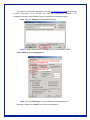
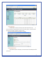
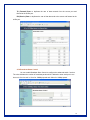
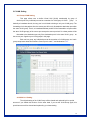
24 Port Fast Ethernet Switch
with VLAN and Trunking
User Manual
Model # ANS-24RV
FCC Warning
This equipment has been tested and found to comply with the limits for a Class A digital
device, pursuant to Part 15 of the FCC Rules. These limits are designed to provide
reasonable protection against harmful interference when the equipment is operated in a
commercial environment. This equipment generates, uses, and can radiate radio
frequency energy, and if it is not installed and used in accordance with the instruction
manual, it may cause harmful interference to radio communications. Operation of this
equipment in a residential area is likely to cause harmful interference, in which case the
user will be required to correct the interference at his own expense.
*Shielded interface cables must be used in order to comply with emission limits
Changes or modifications to the equipment, which are not approved by the party
responsible for compliance, could affect the user's authority to operate the equipment.
Copyright_1999 All Rights Reserved.
Company has an on-going policy of upgrading its products and it may be possible
that information in this document is not up-to-date.
Please check with your local distributors for the latest information.
No part of this document can be copied or reproduced in any form without written
consent from the company.
CE Mark Warning:
This is a Class A product. In a domestic environment, this product may cause radio
interference, in which case the user may be required to take adequate measures.
Trademarks:
All trade names and trademarks are the properties of their respective companies.
2
Contents
1 Introduction ....................................................................................................... 5
1.1 General Description .................................................................................... ..5
1.2 Product Features......................................................................................... ..5
1.3 Package Contents....................................................................................... ..5
1.4 Front Panel LED indicators ......................................................................... ..6
1.5 Rear panel................................................................................................... ..6
1.6 Power Connecting....................................................................................... ..6
1.7 Connecting computers to the switch ........................................................... ..6
1.8 Uplink .......................................................................................................... ..6
1.9 To prolong the operational life to your units ................................................ ..7
2 Installing the Fast Ethernet Switch ................................................................. 8
2.1 Configure system network........................................................................... ..8
2.2 Login the SmartSwitch Web-Base Controller.............................................. ..9
2.3 The SmartSwitch Home overview ............................................................... 10
2.4 Administrator ............................................................................................... 11
2.4.1 Authentication Configuration............................................................... 11
2.4.2 System IP Configuration ..................................................................... 12
2.4.3 System Status..................................................................................... 12
2.4.4 Load Default Setting ........................................................................... 13
2.4.5 Firmware update................................................................................. 14
2.5 Port Management........................................................................................ 16
2.5.1 Port Configuration............................................................................... 16
2.5.2 Port Mirroring ...................................................................................... 17
2.5.3 Bandwidth Control .............................................................................. 17
2.5.4 Broadcast Storm Control..................................................................... 18
2.6 VLAN Setting............................................................................................... 19
2.6.1 Group LVAN Setting............................................................................ 19
2.6.2 Multi to 1 Setting ................................................................................. 19
2.7 Trunk Setting ............................................................................................... 20
2.7.1 Trunk Configuration ............................................................................ 20
2.8 QoS Setting................................................................................................. 21
2.8.1 Priority Mode....................................................................................... 21
3
2.8.2 Class of Service Configuration ........................................................... 21
2.9 MAC Address .............................................................................................. 22
2.9.1 MAC Address Configuration ............................................................... 22
2.10 Configuration............................................................................................. 22
2.10.1 Configuration Backup/Recovery ....................................................... 22
3 Console User Interface ..................................................................................... 24
3.1 Connecting to the Switch Console Port....................................................... 24
3.2 Setup HyperTerminal................................................................................... 24
3.3 Configure Switching Hub via COM1 Port .................................................... 27
3.3.1 Switch Main Menu .............................................................................. 27
3.3.2 Load Default Setting ........................................................................... 27
4
1. Introduction
1.1 General Description
The device is a powerful, high-performance Fast Ethernet switch, with all 24 ports capable of
10 or 100Mbps auto-negotiation operation (Nway) which means the switch could automatically
negotiate with the connected partners on the network speed and duplex mode. It is ideal for
micro-segmenting large networks into smaller, connected subnets for improved performance,
enabling the bandwidth demanding multimedia and imaging applications. Moreover, the
10/100Mbps auto-sensing ability provides an easy way to migrate 10Mbps to 100Mbps network
with no pain. Compared to the shared 10Mbps or 100Mbps networks, the Ethernet Switch delivers
a dedicated 10/100Mbps connection to every attached client with no bandwidth congestion issue.
1.2 Product Features
*Complies with 10BASE-T specifications of the IEEE802.3 standard
*Complies with 100BASE-TX specifications of the IEEE802.3u standard
*RJ-45 ports for 100Base-TX and 10Base-T connectivity
*Supports Nway protocol for speed (10/100Mbps) and duplex mode
(Half/Full) auto-detection
*Supports full and half duplex operation on all ports
*Supports back-pressure (half duplex) and flow control (IEEE802.3x)
*Wire speed packet filtering and forwarding rate
*Store-and-forward architecture filters fragment & CRC error packets
*Port trunks for server/network backbone attachments
*802.1Q VLAN support to enhance security/network performance
*802.1p priority Queues QoS
*Easy configuration through web-based management
*Supports extensive LED indicators for network diagnostics
*Supports MDI/MDI-X auto crossover
*Internal power supply and 19” rack-mount size
1.3 Package contents
-- 24-Port 10/100Mbps Ethernet Switch
-- AC Power Cord
-- Quick Installation Guide CD
-- Two Rack-mounted Brackets
5
-- Eight Screws
*If any of the items is damaged or missing, please contact your retailer immediately.
1.4 Front panel LED indicators
After installing the switch, you can check its status from the LED indicators on the front panel
shown below.
LED
POWER (PWR)
LINK / ACT
Color
Status
Indication
GREEN
ON
The switch is power on
OFF
The switch is power off
ON
A link is established
BLINKING
A link is established and data is being
GREEN
transmitted or received
1.5 Rear panel
Rear Panel of the switching hub has a RS232 Connector, a power cord socket.
1.6 Power Connecting
Plug the circle end of the power cord firmly into the power port on the switch rear panel, and the
other end into an electric service outlet, then the system is ready.
1.7 Connecting computers to the switch
The switch features auto-MDI/MDIX crossover detection function and provides plug-and-play
capability.
Users can immediately use any of the features of this product simply by plugging the
network cables (RJ-45) into the computers and the switch.
1.8 Uplink
All Ports can be used as an uplink port for connecting to another unit without using crossover
6
cable. When using the uplink port, you can extend the distance to 100m for linking another switch
or hub.
1.9 To prolong the operational life of your units
*Never stack units more than eight high if freestanding
*Do not place objects on top of any unit or stack
*Do not obstruct any vents at the sides of the case
7
2. Installing the Fast Ethernet Switch
2.1 Configure system network
The switching hub offers a Web based management software to manage and monitor the
switching hub. Before running the management software, you have to configure your system
network setup.
For Windows 98/98SE and ME, click “Start Æ Settings Æ Control Panel”, double click
“Network” icon, select “Configuration” tab then choose “TCI/IP” to configure system network
setting.
For Windows 2000 and XP, click “Start Æ Control Panel Æ Network and Internet
Connections Æ Network Connections”, then right click LAN icon to configure system network
setting. Below shown the steps to configure network settings in Windows XP:
Step 1: Right click “LAN” icon, and then select “Properties”.
Step 2: Select “Internet Protocol (TCP/IP)”, and then click “Properties”.
8
Step 3: Select “Use the following IP address”, and enter “IP address”, “Subnet mask”, and
“Default gateway” fields, and then click “OK”.
2.2 Login the Web
Step 1: Enter IP address Æ http://192.168.2.1 in the web browser URL field.
Step 2: When Login window pops out, enter “Username” & “Password”. The default Username is
admin and the default Password is system.
9
2.3 The SmartSwitch Home overview
The window below shows the Home page of SmartSwitch:
Administrator Æ1) Authentication Configuration
2) System IP configuration
10
3) System status
4) Load Default Setting
5) Firmware update
Port Management Æ1) Port Configuration
2) Port Mirroring
3) Bandwidth Control
4) Broadcast Storm Control
VLAN Setting Æ1) Group VLAN Setting
2) Multi to 1 Setting
Trunk Setting Æ Trunk Configuration
QoS Setting Æ 1) Priority Mode
2) Class of Service Configuration
MAC Address Æ MAC Address Configuration
Configuration Æ Configuration Backup/Recovery
2.4 Administrator
2.4.1 Authentication Configuration
This page allows you to change your Username & Password. (Maximum up
to 15 characters).
11
2.4.2 System IP Configuration
In this page, you can set and update the IP Address, Subnet Mask, and
Gateway
setting. After filling up the data that you want to change, click “Update” to process the data
changed immediately.
2.4.3 System Status
Click on “System Status” to present the current system status on this screen. It will
show the MAC address, Number of Ports, and System Version.
12
2.4.4 Load Default Setting
This option helps you to reset the device back to the default setting from the
factory. Be aware that the entire configuration will be reset, the IP address of the device will
be set to default setting 192.168.2.1.
Just simply click “Load” to reset the default setting. After the reset
process
is
completed, you will see the screen as below:
13
2.4.5 Firmware update
Before updating the firmware, you should check whether your management
station provides TFTP server and DHCP server. If these 2 services exit on your
management station, you should disable both services by executing the following
procedures:
(1) Click “Control Panel” Æ “System Management Tool” Æ “Service”.
(2) Disable both TFTP server and DHCP server.
(3) Make Sure the Firewall Setting.
-- Since Jounin DHCP/TFTP program utilizes UDP port 67~ port 69 to transfer
data, you should always keep these UDP ports enabled. Make sure both
Windows firewall & Anti-Virus firewall do NOT block the data transfer.
-- To disable the firewall of Windows, please follow the following procedures:
(My Computer) Æ (Control Panel) Æ (Network and Dial-up
connection) Æ select the network connection and click right button Æ (Property) Æ (Advanced).
Do NOT enable the firewall, since the firewall will probably block the UDP port 67 ~ port 69.
-- Take PC-cillin Anti-Virus program for example, you can follow the
procedures listed below to add the exception list to the firewall set up.
Click (Network Security) Æ (Set up) Æ (Exception List) Æ (Add) Æ Enter
the description the IP address range 67-69 Æ select “UDP”.
(4) Download TFTP+DHCP Program from the Web Site.
14
This program can be downloaded from the web site. http://tftpd32.jounin.net/.You don’t need
to install this program. To run TFTPD32 just launch the executable file tftpd32.exe. The
configuration procedure for DHCP/BootP server is illustrated as the following figures.
Step1: Click the “Settings” item and set base Directory.
Step2: To update the firmware through this program, you should select TFTP
server, DHCP server and Syslog server.
Step3: Click the “DHCP Server” item and setup items shown below. After
finishing the settings, click “SAVE” item to save the configuration.
15
(5) Press the “Update” button which is shown on the Web page.
After you press the “update” button, the TFTP procedure starts and the program shows
the throughput of the data transfer as shown below. If no throughput can be seen on this
program, there may be something wrong with your settings. Please go back to check your
setting step by step.
2.5 Port Management
2.5.1 Port Configuration
In Port Configuration, this page will show each port’s status and setting status. You can
set each port’s configuration on the top of page and click “Update” to save the change.
16
2.5.2 Port Mirroring
Port Mirroring is a method of monitoring network traffic that forwards a copy
of
each incoming and/or outgoing packet from one port of a network switch to another port where
the packet can be studied. It enables the manager to keep
Close track of switch performance and alter it if necessary.
2.5.3 Bandwidth Control
Limit speed of any ports. In this page, you can set each port’s TX (transmit) rate and RX
(receive) rate.
17
TX (Transmit) Rate: to duplicate the rate of data transmit from the source port and
forward to the sniffer port.
RX (Receive) Rate: to duplicate the rate of data that send to the source and forward to the
sniffer port
2.5.4 Broadcast Storm Control
You can enable Broadcast Storm Control to configure the advanced switch function.
The value indicates the number of broadcast packet which is allowed to enter each port in one
time unit. One time unit is 10 ms for 100Mbps speed and 100ms for 10Mbps speed.
18
2.6 VLAN Setting
2.6.1 Group VLAN Setting
This page allows user to define Virtual LAN (VLAN) membership by group of
device’s ports. Any individual port can be a member of a VLAN group. A VLAN
group
is
basically a broadcast domain, but any port is not limited to belong to only one VLAN group. The
forwarding rule is that packets from the source port will be only forwarded to destination port within
the same VLAN group. That is, a broadcast/multicast packet will be forwarded to all ports within
the same VLAB group(s) of the source port except the source port itself. A unicast packet will be
forwarded to the destination port only if the destination port is in the same VLAN group
as
the source port. Organize your VLAN groups in this page.
Each row is a group, any individual port can be a member of a VLAN group, and each
group comprises at least two members. Source port is mark “\” and destination is “V”.
2.6.2 Multi to 1 Setting
The original setting of the VLAN Group will be cleared and replaced by this special
structure if you enable this function. On the other hand, if you set the VLAN Group again, this
special structure will be cleared and replaced by your latest setting.
19
2.7 Trunk Setting
2.7.1 Trunk Configuration
Port trunk setting. The trunk hash algorithm can select “Port ID”, “Source
address”,
“Destination address” or “SD &DA”
20
2.8 QoS Setting
In some ports that need to have a high priority to manage the data transfer,
should be changed. Set the port’s QoS to high to determine the port will
QoS
always transfer their
data first.
2.8.1 Priority Mode
Before users do the priority setting, you have to check the “Enable High
box at Class of Service page. 24-port Modular Smart Switch offers
Low) queues, which catch the priority information in
based in the incoming frames as
Priority”
2-level priority (High and
the Port-Based, IP/DS based, or VLAN
standard IEEE 802.1Q defines. In this way, the switch
controller guarantees the service for high priority frames to some extent, depending on the load
condition of incoming traffic. (At
least, the high priority service offers better than that
of best effort service). It also provides different service ratio settings for
users to shape
the prioritized frames on the streams in the incoming traffic.
2.8.2 Class of Service Configuration
High/Low Priority setting: Specify high or low priority for each port. The port is in High
priority if the port has a check mark; otherwise, the port is in Low priority.
Default: All ports in LOW priority.
IP/DS base (TOS) priority recognition: Ports with TOS enabled will induce
inspect the specific field of IP packet to control packets priority. Making a
port ID indicates this port is TOS priority recognition
switch to
check mark in front of
enabled.
21
Default: All ports in TOS priority recognition disabled.
VLAN tagging base (TCI) priority recognition: Making a check mark in front of port ID
indicates this port is TCI priority enabled.
Default: All ports in TCI priority recognition disabled.
2.9 MAC Address
2.9.1 MAC Address Configuration
This page allows user define which MAC address can be entry to the port. You can
assign three MAC address for every port. Then only the three users can pas this port. It will lock
them and avoid to hacker.
Default is all “ff.ff.ff.ff.ff.ff”. It means all users can pass.
22
2.10 Configuration
2.10.1 Configuration Backup/Recovery
This function allows you to backup or recovery the latest switch settings. Just
simply enter your password and click “Update” button.
23
3. Console User Interface
3.1 Connecting to the Switch Console Port
User can configure the switch system via terminal emulation program through RS-232
port with baud rate 19200-8-n-1. The RS-232 connector is on the back panel of the switching
hub; make sure you connect the other end of serial port to COM1 of PC.
Note: When you use HyperTerminal with MS Windows 2000, make sure that you have
Windows 2000 Service Pack 2 or later are installed. Otherwise the arrow keys do not
function properly under HyperTerminal’s VT100 emulation.
3.2 Setup HyperTerminal
Please follow the steps to setup the HyperTerminal:
Step 1: Click Start Æ All Programs Æ Accessories Æ Communications Æ
HyperTerminal.
24
Step 2: The Connection windows will appear. Enter terminal “Name”, select
correct icon,
and then click “Ok” button.
Step 3: Select “COM1” in the “Connect using” field and then click “OK”.
25
Step 4: Select “19200” in Bits per second field and click “Apply” & “OK” buttons to save the
settings.
Step 5: Reset or pull out the switch power. And then the HyperTerminal screen will
Wait for a while for system checking and then press “s” to enter the
appear.
console.
Note: If you press other key, you won’t into the console, please reset the
power again and
repeat this step.
26
3.3 Configure Switching Hub via COM1 Port
3.3.1 Switch Main Menu
After you enter the Modular Console, the Switch Main Menu will appear.
3.3.2 Load Default Setting
This page allows user to restore default port settings.
27
In the 1st option to 3rd option (1. Restore switch default setting/2.
Restore
IP
default Setting/3. Restore Login default Setting), just simply press number to restore the
default settings.
Press”4’ to enter Modify IP setting screen:
28