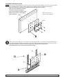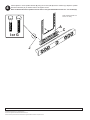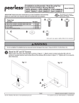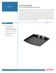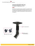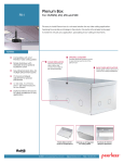
1
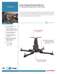
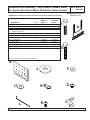
Installation and Assembly - Multi-Channel Speaker Mount
for Boston Acoustics P400 or Polk Audio Center Channel
IMPORTANT! Read entire instruction sheet before you start installation and assembly.
Models: MSA-101,
MSA-101S
MAXIMUM LOAD CAPACITY:
25.00 lb (11.4 kg)
Parts List
A
B
C
D
E
F
G
H
I
J
K
L
DESCRIPTION
center speaker mount
interface bracket
speaker attachment bracket
M5 x 6 mm socket pin serrated
washer head screw
M5 x 10mm socket pin screw
spacer
1/4 x 1.5" hex bolt
1/4" flat washer
3/8 x 1" bolt
flat washer
tear drop locking tab
4 mm security allen wrench
QTY.
1
1
2
4
MSA-101
PART #
087-1041
087-1047
087-1042
510-1114
MSA-101S
PART #
087-4041
087-4047
087-4042
510-1114
1
1
2
2
2
2
1
1
520-1063
540-1032
520-1096
540-9440
520-1242
540-9407
200-1871
560-9646
520-1063
540-1032
520-1096
540-9440
520-1242
540-9407
200-1871
560-9646
I
A
G
Note: some parts may not appear exactly as illustrated.
B
F
J
D
K
H
L
C
E
1 of 4
Visit the Peerless Web Site at www.peerlessmounts.com
ISSUED: 12-19-05 SHEET #: 087-9013-4 05-10-06
For customer service call 1-800-729-0307 or 708-865-8870.
1
Slide speaker attachment brackets (C) onto center speaker (A) mount as shown below.
A
C
C
Installation with adapter plate
2-1
Loosen screws on plasma adapter. Then place interface bracket (B) between plasma adapter and mount. Tighen
screws on plasma adapter securly. Refer to adapter plate instructions for installation of screen.
Skip to step 3.
Note: some parts may not
appear exactly as illustrated.
PLASMA ADAPTER
MOUNT
B
2 of 4
Visit the Peerless Web Site at www.peerlessmounts.com
ISSUED: 12-19-05 SHEET #: 087-9013-4 05-10-06
For customer service call 1-800-729-0307 or 708-865-8870.
Installation directly to screen
2-2
Place interface bracket (B) between screen and mount. Attach interface bracket (B) to mount and screen using fasteners provided with mount. Refer to mount instructions for installation of screen. Tighten all screws securly.
Note: For installation of tear drop locking tab (N) reference SP-850 instruction sheet.
Note: Roll can be adjusted 1° clockwise
or counterclockwise. To adjust roll,
loosen screen fasteners slightly, leaving
them snug. Level screen, then tighten
Note: some parts may not
screen fasteners.
appear exactly as illustrated.
SCREEN
MOUNT
B
3
Attach interface bracket (B) onto center speaker mount (A) using four M5 x 6 mm socket pin serrated washer head
screws (D). Adjust form brackets to best fit your screen size. Tighten screws using 4 mm security allen wrench (L).
Note: For best results use holes closest to the edge of the form brackets as shown below.
Note: Adapter plate, screen, and mount not shown for clarity.
B
D
A
3 of 4
Visit the Peerless Web Site at www.peerlessmounts.com
ISSUED: 12-19-05 SHEET #: 087-9013-4 05-10-06
For customer service call 1-800-729-0307 or 708-865-8870.
4
Attach speaker to center speaker bracket (A) using two screws (I or G) and two washers (J). Adjust the speaker
attachment brackets (C) to desired location and tighten screws.
Note: For Boston Acoustics speakers use two 3/8 x 1" bolt (I) for Polk Audio use two 1/4 x 1.5" hex bolt (G).
Note: Interface bracket not
shown for clarity.
A
C
I or G
J
4 of 4
Visit the Peerless Web Site at www.peerlessmounts.com
© 2006 Peerless Industries, Inc. All rights reserved.
Peerless is a registered trademark of Peerless Industries, Inc.
All other brand and product names are trademarks or registered trademarks of their respective owners.
ISSUED: 12-19-05 SHEET #: 087-9013-4 05-10-06
For customer service call 1-800-729-0307 or 708-865-8870.