1
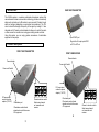
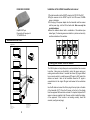
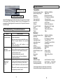
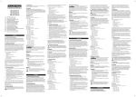
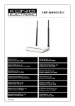
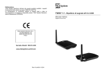
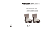
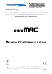
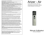
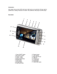
VID-TRANS150KN 2.4GHz WIRELESS AUDIO/VIDEO TRANSMISSION SYSTEM MANUAL PATENT ENGLISH www.konigelectronic.info 0336 Important Safety Precautions This equipment generates and uses radio frequency energy and if not installed and used properly, that is in strict accordance with the manufacture's instructions, may cause interference to radio and television reception. It has been tested and found to comply with the provisions of the 1999/5/EC R&TTE directive, which are designed to provide reasonable protection against such interference in a residential installation. However, there is no guarantee that interference will not occur in a particular installation. If this equipment does cause interference to radio or television reception, which can be determined by turning the equipment off and on, the user is encouraged to try to correct the interference by one or more of the following measures: 1. Reorient the TV/radio antenna. 2. Relocate the Receiver away from the TV/radio receiver. 3. Plug the Receiver into a different wall outlet so that the Receiver is on a different branch circuit. 4. If necessary, the user should consult the dealer or an experienced radio/television technician for additional suggestions. The user is warned that changes or modifications not approved by the manufacturer could void the user's authority to operate the equipment. Linear radio controls provide a reliable communications link and fill an important need in portable wireless signaling. However, there are some limitations which must be observed. The equipment is required to comply with the provisions of the 1999/5/EC R&TTE directive. As such, they have limited transmitter power and therefore limited range. A receiver cannot respond to more than one transmitted signal at a time and may be blocked by radio signals that occur on or near their operating frequencies. Changes or modifications to the device may void R&TTE compliance. 1 A. Contents of the packaging: 1. Transmitter ×1 2. Receiver ×1 3. Power adapter 230VAC to 7.5VDC 300mA ! ×2 4. IR extender with 2,5mm plug For transmitter ×1 5. IR extender with 3,5mm plug For receiver ×1 2 REAR VIEW TRANSMITTER B. Introduction: This 2.4GHz system is a wireless audio/video transmission system that uses advanced wireless communication technology to deliver consistently sharp audio and video up to 80 meters in open area and 30 meters trough walls and ceilings (depending on environment circumstances). The PLL circuit controls the strength and quality of the signal by locking it. It also integrates an UHF remote control extender to allow you to control the audio or video source from another room using your existing remote controller. Using this system, you can enjoy greater convenience of audio/video equipment in many ways. Input SCART port Plug into the AV output port of DVD or VCR or SAT etc. C. Product description: FRONT VIEW TRANSMITTER FRONT VIEW RECEIVER Channel select CH3 or CH4 (NTSC only) Power indicator Power indicator Power on/off switch Power on/off switch RF output to TV (e.g.2058R) DC power input connect to power adapter (7.5V DC) DC power input connect to power adapter (7.5V DC) IR extender port IR extender emits infrared signals and control the source A/V equipment. Channel selection switch. Select same channel on transmitter and receiver IR extender port IR extender emits infrared signals and control the source A/V equipment. 4 3 Channel selection switch. Select same channel on transmitter and receiver REAR VIEW RECEIVER Installation of the 2.4GHz transmitter and receiver: Output SCART port Plug into the A/V input port of TV, MONITOR, etc. 1. Plug the transmitter into the SCART output port of VCR, DVD or SAT. 2. Plug the receiver into the SCART input of the LCD screen, PLASMA screen or television. 3. Put the plug of the power adapter into the transmitter and the receiver and the power plug into the 230-volt wall outlet. Note: use only the provided adapters. 4. Select the desired channel with a combination of the switches (see below figure) If a channel gives some distortion in picture and sound try another combination of the switches. D. Installation overview: A p p lic a tio n : ROOM 1 1 . In s ta lla tio n : ROOM 2 D e s k t o p 4 2 " T F T M o n ito r TX DVD RX SAT R ec e iv er W a ll M o u n t in g 4 2 " T F T M o n ito r IR S e n so r E. Using the remote control feature: RX ROOM 1 2 . O p e ra tio n : ROOM 2 D e s k t o p 4 2 " T F T M o n it o r IR E x ten d e r u d io ) M ou se eo, A z (V id 2 .4 G H MH 4 3 3 .9 2 TX na te S ig em o z IR R DVD IR R e m o te C o n t ro l 4G H z (V i ,A u 4 . 33 92 M H z IR R em ot e S ig na l te ) mo ud io Re IR Hz 2M 43 2.4 W a ll M o u n t in g 4 2 " T F T M o n ito r 3.9 z (V id e IR R e m ote C o n tr o l GH IR E x te n d e r M o use o, A RX S c ar t P lu g to J a c k C a b le ( N o t In c lu d ed ) RX SAT R ec e iv er IR E xten d e r M o u se S ig 2. o de o) di na l RX W a ll M o u n t in g 4 2 " T F T M o n ito r l W a ll M o u n ti n g H older IR R e m ote C o n t ro l The 2.4GHz system not only allows you to send audio/video from one area to another, it also gives you the ability to control the source using your existing remote control device. It converts the infrared (IR) signal emitted by your remote control to a radio frequency (RF) signal in UHF band at the receiver and sends it back to the transmitter where the RF signal is converted back to the original IR signal and beamed to the audio/video source. Use the IR cable and connect the 2.5mm plug to the input jack on the back of the transmitter (IR-T). Place the IR sensor on the front of the display from the equipment that need to be controled. It’s important to place the IR sensor as close as possible to the IR sensor, which is behind the display, of the equipment. If this function is not working correctly, check this accurate. (see figure next page) V id e o S o u rc e s : DVD VCR S A T R e c e iv e r L a s e r D is c P la y e r C a m c o rd e r A u d io S o u rc e s : C o m p a c t D is k P la y e r S te re o R e c e iv e r C a s s e tte D e c k 5 6 G. Specifications: VCR, DVD, SAT or other IR sensor in front of display Use the IR cable and connect the 3.5mm plug to the input jack on the back of the receiver (IR-R). Place the IR sensor in front of the equipment. For receiving the infrared signals of the remote control it’s important the sensor is placed in sight. F. Troubleshooting, Care and maintenance: Problem Possible solutions No picture or sound Check all connections. Make sure power plugs are pushed all the way in. Check the power switches of the connected equipment Check the power on/off switches on the transmitter and receiver. Interference: Noisy picture or audio Select a different channel by pushing the channel selector button on both transmitter and receiver so that the channels match. If using a microwave oven, turn it off. Remove microwave oven from path between transmitter and receiver. Remote control extender does not work Check the path between the transmitter and the audio/video source and clear any obstructions. Check if the batteries from the remote control are full. Make sure IR extender is properly located on the A/V equipment you wish to control. 7 Transmitter: Operating Frequency Band Maximum Output Level Modulation Channels (4) Video Input Level Audio Input Level Input Port Antenna IR–remote IR output Power Dimensions Weight 2.400GHz~2.4835GHz 10dBm (CE) FM (video and audio) PLL frequency synthesizer 1V p-p @ 75 ohm 1V p-p @ 600 ohm (STEREO) SCART socket Hidden omni-directional 940nm with ON/OFF keying 7.5VDC,150mA 100mm×60mm×22mm 100gr. Receiver: Operating Frequency Band Sensitivity Channels (4) Video Output Level Audio Output Level Output Port Antenna Transmit Frequency IR remote modulation Infrared Freqeuncy Input Power Dimensions Weight 2.400GHz~2.4835GHz -80dBm minimum PLL frequency synthesizer 1V p-p @ 75 ohm 1V p-p@ 600 ohm (STEREO) SCART socket Hidden omni-directional 433.92 MHz ASK 35 KHz~41 KHz 7.5 VDC, 230mA 100mm×60mm×22mm 110gr. System: Operational range Remote control range Operating temperature up to 80 meter (line of sight) up to 50 meter (line of sight) 10°C ~ 50°C (14 F ~ 122 F) *Actual range depends on environment circumstances. All specifications subject to change without prior notice 8 DECLARATION OF CONFIRMITY We, Nedis B.V. De Tweeling 28 5215MC ’s-Hertogenbosch The Netherlands Tel.: 0031 73 599 1055 Fax.: 0031 73 599 9699 Email: [email protected] Internet: www.nedis.com Declare under our responsibility that the product; Brandname: König Model: VID-TRANS150KN Description: 2.4GHz wireless transmission system Is in confirmity with the following standards; Radio: EN 300-220-3 (2000-09); EN 300 440 (1999-04) EMC: EN 301 489 (2002-08) LVD: EN 60065: 1998 Following the provisions of the 1999/5/EC R&TTE Directive. Conform this regulation it’s allowed to use this product in all European Community & EFTA countries. Nedis BV is not responsible for the use of this product outside the European Community & EFTA countries. ‘s-Hertogenbosch, 16-08-2005 Mrs. J. Gilad Purchase Director 9