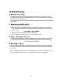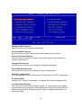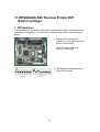
1
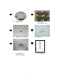
K892 User Manual P/N: 48201250 2006 August V1.0 Copyright 2006 August All Rights Reserved Manual Version 1.0 The information contained in this document is subject to change without notice. We make no warranty of any kind with regard to this material, including, but not limited to, the implied warranties of merchantability and fitness for a particular purpose. We shall not be liable for errors contained herein or for incidental or consequential damages in connection with the furnishing, performance, or use of this material. This document contains proprietary information that is protected by copyright. All rights are reserved. No part of this document may be photocopied, reproduced or translated to another language without the prior written consent of the manufacturer. TRADEMARK Intel®, Pentium® and MMX are registered trademarks of Intel® Corporation. Microsoft® and Windows® are registered trademarks of Microsoft Corporation. ELO Touch is the registered trademark of ELO Touch Systems. 2 Safety IMPORTANT SAFETY INSTRUCTIONS 1. To disconnect the machine from the electrial power supply, turn off the power switch and remove the power cord plug from the wall socket. The wall socket must be easily accessible and in close proximity to the machine. 2. Read these instructions carefully. Save these instructions for future reference. 3. Follow all warnings and instructions marked on the product. 4. Do not use this product near water. 5. Do not place this product on an unstable cart,stand,or table.The product may fall, causing serious damage to the product. 6. Slots and openings in the cabinet and the back or bottom are provided for ventilation;to ensure reliable operation of the product and to protect it from overheating. These openings must not be blocked or covered.The openings should never be blocked by placing the product on a bed, sofa, rug, or other similar surface.This product should never be placed near or over a radiator or heat register,or in a built-in installation unless proper ventilation is provided. 7. This product should be operated from the type of power indicated on the marking label.If you are not sure of the type of power available, consult your dealer or local power company. 8. Do not allow anything to rest on the power cord. Do not locate this product where persons will walk on the cord. 9. Never push objects of any kind into this product through cabinet slots as they may touch dangerous voltage points or short out parts that could result in a fire or electric shock. Never spill liquid of any kind on the product. CE MARK This device complies with the requirements of the EEC directive 89/336/EEC with regard to “Electromagnetic compatibility” and 73/23/EEC “Low Voltage Directive”. FCC This device complies with part 15 of the FCC rules. Operation is subject to the following two conditions: (1) This device may not cause harmful interference (2) This device must accept any interference received, including interference that may cause undesired operation. 3 CAUTION ON LITHIUM BATTERIES There is a danger of explosion if the battery is replaced incorrectly. Replace only with the same or equivalent type recommended by the manufacturer. Discard used batteries according to the manufacturer’s instructions. LEGISLATION AND WEEE SYMBOL 2002/96/EC Waste Electrical and Electronic Equipment Directive on the treatment, collection, recycling and disposal of electric and electronic devices and their components. The crossed dustbin symbol on the device means that it should not be disposed of with other household wastes at the end of its working life. Instead, the device should be taken to the waste collection centers for activation of the treatment, collection, recycling and disposal procedure. To prevent possible harm to the environment or human health from uncontrolled waste disposal, please separate this from other types of wastes and recycle it responsibly to promote the sustainable reuse of material resources. Household users should contact either the retailer where they purchased this product, or their local government office, for details of where and how they can take this item for environmentally safe recycling. Business users should contact their supplier and check the terms and conditions of the purchase contract. This product should not be mixed with other commercial wastes for disposal. 4 Table of Contents 1. CHECKLIST......................................................................................................6 1.1. STANDARD ITEMS (BIG BOX)..........................................................................6 1.2. STANDARD ITEMS (SMALL BOX)......................................................................6 2. SYSTEM VIEW.................................................................................................8 3. MEDIA CARD READER....................................................................................9 4. I/O CONNECTORS (MOTHERBOARD) VIEW ...............................................10 5. DRIVERS INSTALLATION .............................................................................. 11 5.1. DRIVER LIST ............................................................................................... 11 5.2. CHIPSET DRIVER INSTALLATION .................................................................... 11 5.3. USB 2.0 DRIVER INSTALLATION ....................................................................13 5.4. VGA DRIVER INSTALLATION .........................................................................15 5.5. ELO TOUCH DRIVER INSTALLATION ..............................................................17 5.6. LAN DRIVER INSTALLATION ..........................................................................20 5.7. AUDIO DRIVER INSTALLATION .......................................................................21 5.8. BLUETOOTH DRIVER INSTALLATION ...............................................................21 5.9. EPSON-BA-500 THERMAL PRINTER DRIVER INSTALLATION ...........................23 6. SYSTEM INSTALLATION ...............................................................................24 6.1. HDD INSTALLATION.....................................................................................24 6.2. LCD PANEL INSTALLATION ...........................................................................28 6.3. THERMAL PRINTER INSTALLATION .................................................................29 7. SYSTEM REPLACEMENT .............................................................................31 7.1. 7.2. 7.3. 7.4. LOAD THE PAPER OF THE THERMAL PRINTER.................................................31 MOTHERBOARD REPLACEMENT....................................................................33 CONTROL BOARD AND INVERTER BOARD REPLACEMENT ................................36 LCD AND TOUCH SCREEN REPLACEMENT.....................................................39 8. SPECIFICATION.............................................................................................41 9. JUMPER SETTINGS ......................................................................................43 10. BIOS SETTING.............................................................................................47 11. EPSON-BA-500 THERMAL PRINTER DIP SWITCH SETTINGS .................50 1. Checklist Carefully take the system out of the carton. The package includes the following items: 1.1. Standard Items (Big Box) a. System (1) b. Rubber Foot (2) 1.2. Standard Items (Small Box) c. HDD (1) d. Thermal Printer (1) e. f. Holder (1) LCD Panel (1) 6 e. Driver CD (1) f. Screws (4) <for Rubber Foot> g. Screws (2) <for HDD> h. Key (2) i. NI Screws (4) <for LCD Panel> j. User Manual 7 2. System View Front View Right Side View Touch Screen Key Lock Media Card Reader Thumbscrew Thermal Printer Racks Air Flow Vent Rubber Foot 8 3. Media Card Reader 6 5 4 3 2 1 USB IR PRO-Gear XL6 Insert the card into the reader gently all the way in, with the label on the card facing upwards. If the card has an arrow, make sure it points towards the reader. PRO-Gear XL6 supports the following widely used flash media cards: ¾ Compact Flash Type-I ¾ Compact Flash Type-II ¾ Compact Flash Extreme-III (133x) CF 1 ¾ MicroDrive ¾ Magicstor 2 SD/MMC 3 MS 4 xD 5 miniSD 6 SM ¾ ¾ ¾ ¾ ¾ ¾ ¾ ¾ ¾ ¾ ¾ ¾ ¾ ¾ ¾ ¾ ¾ ¾ ¾ ¾ ¾ Secure Digital Secure Digital V1.1 (133x) MMC MMCplus V4.0 MMCmobile RS-MMC RS-MMC V4.0 Memory Stick PRO Memory Stick PRO Duo Memory Stick PRO MagicGate Memory Stick Memory Stick Duo MagicGate Memory Stick Select Memory Stick Duo MagicGate Memory Stick MagicGate Memory Stick Duo Memory Stick Rom Memory Stick Extreme III (133x) xD-Picture Card xD-Picture Card V1.2 miniSD ¾ SmartMedia Card 9 ¾ ¾ NOTICE Please stop reading the card before removing it from the reader to avoid data loss or damage to the card or reader. Memory cards can only be inserted one way. Forcing the card may damage the card reader 4. I/O Connectors (Motherboard) View Handle DC Power Cable LCD Cable Cash Drawer 2 LPT COM4 IDE Cable 2nd VGA USB3 USB4 Mouse COM1 COM2 Keyboard Cash Drawer 1 COM3 10 LAN 5. Drivers Installation 5.1. Driver List Folder/File File Description <CD>:\K892_B81.htm B81 Driver List <CD>:\Common\INTEL\Chipset Chipset Driver <CD>:\Common\INTEL\USB2.0 USB 2.0 Driver <CD>:\Common\INTEL\VGA\i85x VGA Driver <CD>:\Common\Elo_Touch ELO Touch Screen Driver <CD>:\Common\Lan_driver\R8139_810x 10/100Mb LAN Driver USB Interface C-Media102 Audio Driver IVT BlueSoleil Bluetooth V1.1 Driver <CD>:\Common\USB 20Audio\C-Media 20CM102 <CD>:\Common\Bluetooth\IVT_BlueSoleil <CD>:\Common\Bluetooth\WINCOMM_BC WINCOMM BCM2045A Bluetooth M2045A V2.0 Driver <CD>:\Common\printer\EPSON BA-T500 EPSON Thermal Printer Driver The following procedures are for Windows 2000/XP, other platforms are similar. 5.2. Chipset Driver Installation a. Double click “infinst_enu_6.0.1002” on the “My Computer” window. b. Click the “Next” button on the “Welcome” window. 11 c. Click the “Yes” button on the “License Agreement” window. d. Click the ”Next” button on the “Readme Information” window. e. Click the “Finish” button and restart your system. 12 5.3. USB 2.0 Driver Installation OS Requirements OS USB 2.0 requirements Windows XP USB 2.0 drivers are provided in Service Pack 1 (SP1) for Windows XP, which is available through Windows Update. Windows 2000 USB 2.0 drivers are available through Windows Update or Service Pack 4. Windows 98SE/Me USB 2.0 drivers are available on the Intel developer site. Windows 98 (Retail) Developers and OEMs should contact Orange Ware. For end-users, if your device does not ship with Windows 98 drivers, contact your device or system manufacturer. If USB 2.0 drivers are not available, your device will operate at USB 1.1 speeds Linux USB 2.0 support is available in kernel 2.4.19 or later development kernels, or in the 2.4.19 or later production kernel. More information. a. Right click “My Computer” on the windows desktop and select “properties”. b. Select “Hardware”Æ”Device Manager” on system properties. 13 c. Select ”Other Devices” Æ “Universal Serial Bus (USB) Controller” Æ”Properties” in the Device Manager. d. Select “Device”Æ “Update Driver…”. e. Click the ”Next” button on the “Welcome” window. f. Select “Search for a suitable…”and click the “Next” button on the “Install Hardware Device Drivers” window. g. Select “Specify a location” and click the “Next” button on the “Locate Driver Files” window. 14 h. Press “Browse” to select driver and then click the “OK” button to next page. i. Click the “Next” button on “Driver Files Search Results” window. j. Click the “Finish” button to complete this process. k. Finished. 5.4. VGA Driver Installation a. Double click “win2k_xp147” on the “My Computer” window. b. Click the “Next” button on the “Welcome” window. 15 c. Click the ”Next” button on the “Welcome window”. d. Click the ”Yes” button on the “License Agreement” window. e. Click the ”Finish” button and restart your system. 16 5.5. ELO Touch Driver Installation a. Click ”sw500930” on the My computer window. b. Click the “OK” button on the Welcome window. c. Click the ”Unzip” button on the WinZip Self-Extractor window. d. Select “Install Serial Touchscreen Drivers” and then click the “Next” button on the Welcome window. 17 e. Click the “Yes” button on the License Agreement window. f. g. Select “COM5” and click the “Next” button on the Choose the COM ports… window. h. Click the “Next” button on the You have selected the COM ports…window. 18 Click the “Next” button on the on the “Select the COM ports…” window. i. Click the “Finish” button on the Setup Complete window j. k. After the computer restarted, click “Align” on the Elo Touchscreen Properties window. Click the “Yes” button and restart your system. l. Calibrate three red points. 19 5.6. LAN Driver Installation a. Double click ”Setup” on the “My Computer” window. b. Click the “Finish” button on the “Maintenance complete” window. c. Click the ”OK” button and restart your system. 20 5.7. Audio Driver Installation a. Select “Setup” on the “My Computer” window. b. Click the “Finish” on the “USB Audio Installation-InstallShield Wizard” window. 5.8. Bluetooth Driver Installation a. Click the ”IVT BlueSoleil Bluetooth” on the ”Manual list” window。 b. Click the ”Win98_ME_2K_XP_V1611” on the ”IVT_BlueSoleil” window。 21 c. Click the “Setup” on the “Win98_ME_2K_XP_V1611” window. d. Select the language and then click the “OK”. e. Click the “Next” on the “IVT BlueSoleil Setup” window. f. Click the “Yes” on the “IVT BlueSoleil Setup” window. g. Click the “Next” on the “IVT BlueSoleil Setup” window. h. Click the ”Yes” and restart your system. 22 5.9. EPSON-BA-500 Thermal Printer Driver Installation a. Click on the “EPSON-BA-T500” link on the window. b. Select “I accept…” and click the “Next” button on the “License Agreement” window. c. Click the ”Next” on the “Location to Save Files” window. d. Select your Operating system and click “Next” on the “Select OS window”. 23 e. Select “Parallel Driver” and “EPSON BA-T500” Receipt and click “Finish” on the “Select Module” window. f. Click the ”Yes” button and restart your system. 6. System Installation 6.1. HDD Installation a. Insert the key into the lock and unlock the LCD module. b. Lift the LCD module up. 24 c. Loosen the thumbscrew (1). d. Open the drawer by pulling it towards you. e. Remove the screws (2) of the card reader cover. 25 f. Remove the card reader cover screws (2) as shown in the picture. g. Remove the card reader cover. h. Disconnect the USB cable (1) and power cable (1). 26 i. Remove the screws (2) as shown in the picture. j. Connect the IDE cable (1) and the power cable (1). k. Carefully place the HDD next to the fan. Tighten the screws (2). 27 6.2. LCD Panel Installation a. Carefully place the LCD module on the bracket. Two bolts lodge in the holes to prevent the LCD from sliding off (see picture). b. Fasten the screws (4). c. Connect the DVI cable (1). Finish LCD module installation. 28 6.3. Thermal Printer Installation a. Loosen the thumbscrew (1). b. Open the drawer by pulling it towards you. c. Remove the screws (2) of the right hand side bracket. 29 d. Two bolts lodge in the holes of the brackets as shown in the picture. e. Fasten the screws (2). f. Connect the power cable and printer cable of the rear thermal printer as shown in the picture. 30 g. Finish the thermal printer installation. 7. System Replacement 7.1. Load the Paper of the Thermal Printer a. Loosen the screw (1). b. Open the drawer by pulling it towards you. 31 c. Slide the thermal printer box towards the front of the drawer. d. Cut away the first five (5) cm of the paper, to obtain a straight edge and remove the label at the end of the roll. e. Put the paper holder through the paper roll. 32 f. Keep the paper flat to load the paper into the printer slot. Do not fold the paper. The paper will feed automatically through the printer (the system must be powered on). 7.2. Motherboard Replacement a. Insert the key into the lock and unlock the LCD module. b. Lift the LCD module up. 33 c. Disconnect all the cables: - COM Port cables (2), - HDD cable (1) - power cable (1) - DVI cable (1) - LAN cable (1) - USB cable (1) Please also refer to chapter 2., I/O Connectors (Motherboard) View. d. Disconnect the USB cable (1) and power switch cable (1) as shown in the picture. e. Remove the screw (1) next to the chassis box. 34 f. Remove the chassis box by from the system by the handle. g. Remove the screws (2) (one on each side). h. Hold the handle and lift the cover. 35 i. Disconnect all cables of the motherboard: - LCD cable (1) - Bridge cable (1) - USB cable (1) - Power cable (1) - IDE cable (1) - Flat 40P cable (1) - 20P/4P cable (1) - DVI cable (1) - Power cable (1)。 j. Remove the screws (2) (one on each side). Slide the motherboard towards you and remove it. 7.3. Control Board and Inverter Board Replacement a. Insert the key into the lock and unlock the LCD module. 36 b. Lift the LCD module up. c. Disconnect the DVI cable (1) from the LCD Module. d. Remove the screws (4) (one on each side). 37 e. Carefully remove the LCD module. f. Disconnect the T/S cable (1), the Control Board cable (1) and the 2P cable (1) from the control board. g. Remove the screws (4) to replace the control board. 38 h. Disconnect the LCD cables (3) and remove the screws (2) to replace the inverter board. 7.4. LCD and Touch Screen Replacement a. Remove the screws (5). b. Carefully press in the two sides to separate the back housing from the LCD chassis. 39 c. Carefully disconnect the T/S cable (1). d. Remove the screws (6) of the LCD chassis to separate the LCD from the touch screen. e. Replace the LCD。 40 f. Remove the screws (12) of the brackets (4) to replace touch screen. 8. Specification Mainboard CPU Supports Core Logic System Memory Graphic Memory Mini PCI Socket LCD Touch Panel LCD Size Brightness Maximal Resolution Touch Screen Type Tilt Angle (Degree) Storage Devices HDD Expansion Mini-PCI Socket Internal I/O Ports Internal Speaker PS/2 Keyboard PS/2 Mouse USB Serial / COM Parallel B81 Intel P4 Celeron 2.5G Intel 852GM and ICH4 2 x DDR DIMM sockets supported with memory size up to 2GB UMA Share Memory 8MB ~ 64MB 1 x Mini PCI socket supported 15”TFT 350 cd/㎡ 1024 x 768 Resistive / Saw (by request) 60° 1 x 3.5” HDD Drive Bay 1 x mini-PCI slot 2 x 3W 1 1 4 x USB port (USB 2.0) 4 (Pin 1 / 9 with 5V / 12V) 1 41 Internal I/O Ports Serial / COM LAN (10/100) VGA 2 nd VGA Cash Drawer Port Control / Indicator Power Button Power Power Supply Environment EMC & Safety Operating Temperature Storage Temperature Operating Humidity Storage Humidity Peripheral Thermal Printer Media Card Reader Chassis Lock Key Optional Module Wireless LAN Bluetooth UPS POP Shelf Dimension (W x D x H) Weight OS Support 4 x powered COM ports (pin 1 / pin 9 support +5V / +12V by Jumper) 1 x RJ-45 Jack 1 x LCD Monitor interface (LVDS / Inverter / USB) 1 x male type connector with power 2 x RJ11 Cash Drawer with 12V / 24V 1 Internal 250W ATX switching mode power supply FCC, Class A, CE, LVD, BSMI 5℃~ 35℃ (41℉~ 95℉) -10℃~ 60℃ (14℉~140℉) 10% - 90% RH non condensing 10% - 90% RH non condensing 80mm Thermal Printer Planar Flash Media Card Reader (with IrDA) 1 USB Dongle USB Dongle 1 1 370 x 193 x 1370mm / 14.6”x 7.6” x 53.9” 48.6kg / 107.14lb Windows 2000, XP - This specification is subject to change without prior notice. 42 9. Jumper Settings Motherboard JP3 JP5 JP6 JP15 JP14 JP13 JP12 JP10 JP11 JP1 JP2 JP4 JP9 43 Jumper Setting ◎ Factory Default Setting 1.CPU Frequency setting Function FSB400 FSB533 JP4 (SHORT) ◎1-2, 3-4 3-4 2. Compact Flash Master/Slave setting Function Master Slave 3. CMOS Operation mode Function CMOS Normal CMOS Reset To clear the CMOS: 1) Remove AC power from the unit. 2) Open the cabinet. 3) Change the JP6 jumper setting from N/C to 1-2. 4) Wait 1 minute. 5) Change the JP6 jumper setting back to N/C. 6) Close the cabinet. 7) Apply AC power and continue. 4. POWER USB Power setting (Reserved) Function +24V +12V 5. Cash Drawer Power setting Function Cash Drawer 1 +12 V +24V Cash Drawer 2 +12 V +24V JP3 (SHORT) ◎1-2 N/C JP6 (SHORT) ◎N/C 1-2 JP14 (SHORT) 1-2 3-4 JP8 (SHORT) ◎1-2 3-4 ◎5-6 7-8 44 6. COM1 Power setting Pin 1 9 7. COM2 Power setting Pin 1 9 8. COM3 Power setting Pin 1 9 9. COM4 Power setting Pin 1 9 Function DCD# +5V +12V RI# +5V +12V JP9(SHORT) ◎1-2 3-4 5-6 ◎7-8 9-10 11-12 Function DCD# +5V +12V RI# +5V +12V JP11(SHORT) ◎1-2 3-4 5-6 ◎7-8 9-10 11-12 Function DCD# +5V +12V RI# +5V +12V JP10(SHORT) ◎1-2 3-4 5-6 ◎7-8 9-10 11-12 Function DCD# +5V +12V RI# +5V +12V JP12(SHORT) ◎1-2 3-4 5-6 ◎7-8 9-10 11-12 10. CPU Voltage setting CPU Type JP1 (SHORT) 1-2, 3-4, 5-6, 7-8, 9-10, 11-12 ◎P4 P4-M (1.3V) N/C 45 JP2 (SHORT) N/C 3-4, 9-10 11. LCD ID setting Panel Resolution Number 0 640 x 480 LVDS JP5 Bits Channel 1-2 3-4 5-6 7-8 18 Single SHORT SHORT SHORT SHORT 1 800 x 600 18 Single SHORT SHORT SHORT 2 1024 x 768 18 Single SHORT SHORT OPEN SHORT 3 1280 x 1024 24 Dual SHORT SHORT OPEN OPEN 4 1024 x 768 24 Single SHORT OPEN SHORT SHORT 5 800 x 600 24 Single SHORT OPEN SHORT 12. Second Display Power setting Function +12V NC JP15 (SHORT) 1-2 ◎1 13. Power Mode setting Function ATX Power AT Power JP13 (SHORT) ◎N/C 1-2 Note: OPEN SHORT 46 OPEN OPEN 10.BIOS Setting 1. BIOS Setup Utility The BIOS setup defines how the system is configured. You need to run this program the first time you configure this product. You may need to run it again if you change the configuration. You need to connect a PC keyboard to the keyboard connector to run the BIOS setup utility. 2. Starting the BIOS Setup 1. Turn on or reboot this product. 2. Press the DEL key immediately after the product is turned on, or press the DEL key when the following message is displayed during POST (the Power on Self-Test). Press DEL to enter SETUP. 3. The main menu of the BIOS setup is displayed. 4. If the supervisor password is set, you must enter it here. 3. When a Problem Occurs If, after making and saving system changes with the Setup utility, you find that this product no longer boots, start the BIOS setup and execute the following. Load Optimized Defaults 4. BIOS Main Menu When the BIOS Main Menu is displayed, the following items can be selected. Use the arrow keys to select items and the Enter key to accept and enter the sub-menu. Note: The BIOS menu below is from B81 BIOS version B81FV10D.BIN. If you have a different BIOS version, the contents of the menu may different. 47 Standard CMOS Features Use this menu for basic system configuration. Advanced BIOS Features Use this menu to set the Advanced Features available on the system. Advanced Chipset Features Use this menu to change the values in the chipset registers and optimize the system’s performance. Integrated Peripherals Use this menu to specify your settings for integrated peripherals. Power Management setup Use this menu to specify your settings for power management. PnP/PCI Configurations This entry appears if your system supports Plug and Play and PCI Configuration. PC health status Displays CPU, System Temperature, Fan Speed, and System Voltages Value. Load Optimized Defaults Use this menu to load the BIOS default values, i.e., factory settings for optimal performance system operations. While Award has designed the custom BIOS to maximize performance, the factory has the option to change these defaults to meet their needs. 48 Set Supervisor Password Enables you to change, set, or disable the supervisor or user password. Set Password Change, set, or disable the password. It allows you to limit access to the system and to the setup, or just to the setup. Save & exit setup Save CMOS value changes to CMOS and exits setup. Exit without saving Ignores all CMOS value changes and exits setup. 49 11.EPSON-BA-500 Thermal Printer DIP Switch settings 1. DIP Switches There are two DIP switches on the printer control board, which is mounted on the rear panel of the system. To access the switches, please follow the instructions below a. The two DIP switches are located in the top right part of the printer control board. The DIP switch number is printed on the board. b. The illustration shows the layout of the DIP switches. 50 2. DIP Switch 1 (DSW1) SW Function No. 1 Black Mark sensor 2 Interface selection 3 ON OFF Enabled Disabled Refer to Table 2.1. Yes DTR/DSR or CTS/RTS No Off (*1) Even Odd Off (*1) 4 Serial interface handshaking XON/XOFF 5 Serial interface parity check Serial interface parity selection Serial interface baud rate selection 6 7 8 Refer to Table 2.2. (*1) Effective only when the serial interface is selected. Table 2.1 Interface Selection Interface Parallel interface (IEEE 1284) Serial interface (RS-232) Optional interface Switch number 2 3 Off Off Off On On On or Off Table 2.2 Baud Rate Selection Transmission Speed (bps) 4800 9600 19200 38400 bps: bits per second Switch number 7 8 On On Off On On Off Off Off 51 Factory setting Off Off Off Off (*1) Off (*1) Off (*1) 3. DIP Switch 2 (DSW2) SW No. 1 2 3 4 5 6 7 8 Function ON OFF Model type selection Refer to Table 3.1 Print density selection Refer to Table 3.2 Operation mode selection Factory use I/F pin 6 reset signal-1 I/F pin 6 reset signal-2 Refer to Table 3.3 Enabled Enabled Disabled Disabled Factory setting On Off On Off Off Off Off Off Table 3.1 Model selection Model M-T540 (82.5 mm paper-width model) (640 dots, 3.25") (*1) M-T530 (79.5 mm paper-width model) (576 dots, 3.15") M-T520 (60 mm paper-width model) (448 dots. 2.36") M-T510 (58 mm paper-width model) (432 dots. 2.28") (*1) The K892 is supplied with the M-T540 printer Table 3.2 Print Density Selection Switch Number Level Print Density 3 4 1 Slightly Light On On 2 Normal Off Off 3 Slightly dark On Off 4 Dark Off On Table 3.3 Operation Mode Selection Switch Number Operation mode 5 Hexadecimal dump Off Normal Off 52 Switch Number 1 2 Off Off On Off Off On On On