1
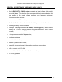
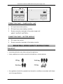
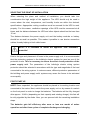
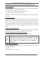
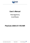
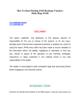
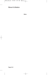
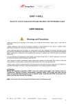
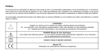
Instruction manual for SPECLINE series power supply units
TABLE OF CONTENTS
TABLE OF CONTENTS........................................................................................................................................ 2
INTRODUCTION .................................................................................................................................................. 3
GENERAL INFORMATION ................................................................................................................................. 3
INTENDED APPLICATION OF THE POWER SUPPLY UNIT..................................................................... 3
GENERAL DESCRIPTION OF THE POWER SUPPLY UNITS .................................................................... 4
STRUCTURE OF THE POWER SUPPLY UNIT WITH A BATTERY MODULE ............................................. 5
INDUSTRIAL WORK SAFETY INSTRUCTIONS.............................................................................................. 6
TRANSPORT .................................................................................................................................................... 6
ELECTRICAL SAFETY ................................................................................................................................... 7
INSTALLATION.................................................................................................................................................... 7
UNPACKING .................................................................................................................................................... 7
SELECTING THE POINT OF INSTALLATION............................................................................................. 8
FIRST START-UP............................................................................................................................................. 8
SWITCHING THE POWER SUPPLY UNIT ON WITHOUT A MAINS CONNECTION – “COLD START”
............................................................................................................................................................................ 9
BATTERY MODULE INSTALLATION ............................................................................................................ 10
CONNECTING BATTERY MODULE........................................................................................................... 10
CONNECTING THE BATTERY.................................................................................................................... 10
DESCRIPTION OF THE OPERATION OF THE POWER SUPPLY UNIT ...................................................... 11
GENERAL INFORMATION .......................................................................................................................... 11
PROTECTION DEVICES INCORPORATED IN THE POWER SUPPLY UNIT......................................... 12
COMMENTS REGARDING OPERATION ........................................................................................................ 13
FUSE REPLACEMENT .................................................................................................................................. 13
INTERACTION WITH ELECTRICAL GENERATORS ............................................................................... 13
OUTPUTS........................................................................................................................................................ 13
STORAGE, MAINTENANCE, AND TRANSPORT...................................................................................... 13
UTILISATION................................................................................................................................................. 14
TECHNICAL PARAMETERS............................................................................................................................. 15
INFORMATION ON LEGAL PROVISIONS AND THE GUARANTEE .......................................................... 16
DECLARATION OF CONFORMITY ............................................................................................................ 16
GUARANTEE ................................................................................................................................................. 16
2011/07/22
www.ever.eu
2
Instruction manual for SPECLINE series power supply units
INTRODUCTION
Thank you for purchasing the EVER SPECLINE UPS power supply unit. It
belongs to our most modern, state-of-the-art series of technologically advanced
power supply units, which is primarily intended for securing the uninterrupted
operation of central heating boilers, fireplaces with water jackets, pumps, and solar
systems. The installation of a unit from this series guarantees correct operation for
many hours in the event of a power outage, thanks to the series connection of battery
module modules. In battery operation mode, the Clear Digital Sinus (CDS) system
enables the equipment to generate a sinusoidal waveform at output.
Specline series UPS units have been designed in such a way as to best meet all of
your expectations regarding protection against the consequences of power outages.
The power supply units are manufactured in Poland, in full compliance with the
requirements introduced for the CE mark.
GENERAL INFORMATION
INTENDED APPLICATION OF THE POWER SUPPLY UNIT
The EVER SPECLINE 700 power supply unit protects all equipment that is
connected to it against voltage decays and drops, and eliminates the possibility of
damage arising from overvoltage in the mains. Its primary application is to secure the
operation of central heating boilers, fireplaces with water jackets, solar systems, as
well as control and automatic control engineering systems, which require extended
support times. It can also be used to power telecommunications equipment
(exchanges, faxes) and alarm systems. If you need to protect other, specific
receivers, please contact our technical support department.
2011/07/22
www.ever.eu
3
Instruction manual for SPECLINE series power supply units
GENERAL DESCRIPTION OF THE POWER SUPPLY UNITS
•
the CLEAR DIGITAL SINUS system generates an input voltage with a perfect
sinusoidal shape. This solution offers more opportunities to connect devices that
are sensitive to the supply voltage waveform, e.g.: laboratory equipment,
telecommunication devices;
•
synchronisation with the mains;
•
“cold start” – the unit can be started without being connected to the mains;
•
discharged battery sound indication;
•
intelligent charging method Cool Battery Charging (CBC), which extends
battery life - a novel charging method using the components of the internal
inverter;
•
microprocessor control of all parameters;
•
overload resistance;
•
short circuit protection;
•
system of passive mains filters;
•
possibility of connecting up to three battery module or a car battery
•
with a capacity up to 150 Ah;
•
convenient and universal method of cable connection;
•
24 month guarantee;
2011/07/22
www.ever.eu
4
Instruction manual for SPECLINE series power supply units
STRUCTURE OF THE POWER SUPPLY UNIT WITH A
BATTERY MODULE
UPS
BATTERY MODULE
FRONT PANEL
1. The red signalling diode depicts various operating modes of the power supply
unit, symbolically expressed by means of graphical symbols:
a) red diode continuously on: mains power mode.
b) red diode flashing every 2.5 sec.: battery charging mode.
c) red diode flashing and an intermittent sound signal: battery operation
mode; if the signal becomes continuous, this means that the UPS will shut
down in max. 30 sec.
d) red diode flashes rapidly and the sound signal reaches a high pitch: an
overload or short-circuit condition.
2. Main switch – in the event of a power outage or when the power supply unit is
not connected to the mains, it starts the power supply unit in battery operation
mode – cf. also “cold start”.
2011/07/22
www.ever.eu
5
Instruction manual for SPECLINE series power supply units
CONNECTION PANEL – POWER SUPPLY UNIT
1.
AC input fuse socket (mains)
2.
DC input fuse socket (battery module)
3.
Screw connection terminals of the power supply unit
(INPUT, OUTPUT, BATTERY)
CONNECTION PANEL – BATTERY MODULE
4.
DC output fuse socket
5.
Screw connection terminals of the battery module
INDUSTRIAL WORK SAFETY INSTRUCTIONS
TRANSPORT
•
exercise particular care when moving the appliance;
•
heavy appliances must be moved by at least two or more persons;
•
the appliance should be operated and stored in conditions concordant with those
set in the specification;
2011/07/22
www.ever.eu
6
Instruction manual for SPECLINE series power supply units
ELECTRICAL SAFETY
•
The appliance should be operated and stored in conditions concordant with
those set in the specification.
•
In the event of a brief short-circuit, the high current may cause serious burns.
•
Before connecting the appliance, it is necessary to check the technical condition
of connectors and cables, as well as that of the appliance itself.
•
The appliance must be connected to the mains by means of tri-lead cables;
remember to maintain the correct order of connections. Incorrect connections
may result in electric shock.
•
The appliance channels leak current from the receivers through a protected lead
– nevertheless, the total leakage current should not exceed 3.5 mA.
•
It is strictly forbidden for the user to perform any repair work, as this would
constitute a threat to health and/or life. All repairs and replacement of the
battery module must be carried out exclusively by qualified service personnel.
•
If the device is connected to an external power source, the device’s output
may be live even if the power source is disconnected from the network.
NOTE! EVER SPECLINE 700 power supply units are not intended for
use with medical equipment or with health or life support systems
in particular.
INSTALLATION
UNPACKING
Carry out a visual inspection of the power supply unit immediately upon delivery.
Although the product is solidly packaged, the appliance could have been damaged
due to shocks experienced during transport. If any damage is determined, inform the
carrier or seller.
2011/07/22
www.ever.eu
7
Instruction manual for SPECLINE series power supply units
SELECTING THE POINT OF INSTALLATION
When selecting the place and method of installation, you should take into
consideration the high weight of the appliance. The UPS should only be used in
rooms where the dust, temperature, and humidity levels are within the device's
specifications. Appropriate cooling conditions must be ensured for the UPS to work
properly. For this reason, ventilation openings of the UPS must be uncovered at all
times, and the distance between the UPS and other objects should not be less than
15 cm.
The distance between the power supply unit and the battery modules or battery
should be as small as possible. This makes it possible to use shorter connection
cables, thereby helping to limit cable losses.
NOTE! It is forbidden to install the appliance near flammable
materials!
Due to the type and placement of fuses in the power supply unit, it is recommended
that the protection systems in the building's electric system be used as one of the
protection levels. This is necessary to ensure the short circuit protection of the
power supply unit. The parameters of the building's electric wiring system
protection should be selected in accordance with the type and magnitude of the load
connected to the wiring system. In extreme cases, different protection parameters of
the building and power supply unit’s systems may cause the former to be activated
more rapidly.
FIRST START-UP
NOTE! Once unpacked, the appliance should be placed in its working location and
connected to the mains. Next, switch the power supply unit on by means of a switch
on the front panel in order to charge the batteries. The batteries will be fully charged
after approx. 10-48 h (depending on their capacity and existing charge); this fact will
be duly signalled by the diode. Now, you can proceed with the remaining installation
steps.
The batteries gain full efficiency after more or less one month of mains
operation and after three cycles of complete discharge and charging.
2011/07/22
www.ever.eu
8
Instruction manual for SPECLINE series power supply units
In order to verify whether the power supply unit is operating correctly, please perform
the following steps:
1. Install the power supply unit in the selected location (e.g. on a wall)
2. Connect the cables to the unit’s connectors and the module
3. Install fuses in the sockets
4. Switch the power supply unit on by pressing the switch on the front panel.
A correctly operating power supply unit, which is connected to a network with the
requisite supply parameters, will signal that it has been switched on by emitting
three sound signals, while the diode will flash three times. Now, you should switch
the protected device on.
In order to perform a test, switch the mains supply of the UPS off (e.g. on the
building’s switchboard) – the UPS should commence operation in battery mode,
while the protected device should function normally. This operating mode is signalled
by the simultaneous flashing of the red diode and an intermittent sound signal. If after
switching the mains supply on the diode starts to flash rapidly and an intermittent
sound signal is emitted, this means that the load connected to the unit is too great
(the power supply unit will operate for approx. 5 sec. and turn itself off). It will be
necessary to disconnect the excessive load.
5. Reconnect the mains supply – after approx. 3 sec., the diode will return to the
“continuous on” state. Once the unit resumes mains operation, the charging
circuit will top up the batteries; this will be signalled by the diode switching off
briefly, approx. every 2.5 seconds.
Please keep in mind that when the power supply unit is working in battery mode and
the red diode starts to flash and the sound signal becomes continuous, the device
will shut down in no more than 30 sec.
SWITCHING THE POWER SUPPLY UNIT ON WITHOUT A MAINS CONNECTION
– “COLD START”
If the mains voltage parameters are incorrect, the unit can be powered on in battery
operating mode and supply devices until normal voltage resumes, or until the battery
is discharged.
In order to use this function, press the “power on” switch on the front panel. The
powered appliance should be switched on. The power supply unit will emit three
short signals, informing that it is ready for operation, and will then switch to the
battery mode. In the case of EVER SPECLINE 700 units, this is signalled by the
flashing of the red diode on the front panel and an intermittent sound signal.
2011/07/22
www.ever.eu
9
Instruction manual for SPECLINE series power supply units
NOTE! Since boiler control systems have varying start-up power
input
requirements,
problems
may
be
encountered
when
attempting to start the UPS and connected devices. If this is the
case, you should try to "cold start" the unit again.
BATTERY MODULE INSTALLATION
CONNECTING BATTERY MODULE
You may connect 1-3 42 Ah battery modules to the power supply unit. Connections
should be made with conductors with a minimum section of 2.5 mm2. The BATERIA 1
(battery module 1) and BATERIA 2 (battery module 2) connectors are connected in
parallel. Both the module and power supply unit are delivered with fuses.
For transport and connection, the fuses should be removed from their sockets.
They should be installed only after all the connections are made!
CONNECTING THE BATTERY
An lead-acid car battery (12 V) with a maximum capacity of 150 Ah may be
connected to the power supply unit.
Connections should be made with conductors with a minimum section of 2.5 mm2.
For detailed information, please visit www.ever.eu
NOTE! Please pay particular attention to the polarity of the
connections (battery “plus” to the power supply unit “plus”,
battery “minus” to the power supply unit “minus”); if they are
reversed, the unit may be damaged and the guarantee thereby
voided.
2011/07/22
www.ever.eu
10
Instruction manual for SPECLINE series power supply units
DESCRIPTION OF THE OPERATION OF THE POWER
SUPPLY UNIT
GENERAL INFORMATION
The fundamental role of the power supply unit is to supply connected devices with
electricity from the attached battery modules or an external battery in the event of
irregularities in the mains supply. The time over which electricity is provided by the
unit depends on the capacity of the battery and on the currently connected load. The
power supply unit utilises circuits that detect extreme operating conditions, i.e. an
overload of the converter and a short-circuit at the input. These circuits are active in
the battery operating mode.
When the mains voltage parameters are correct, the power supply unit switches to
mains operation. In this case, prior to reaching the UPS output, the mains voltage is
filtered in the anti-interference circuitry, where additional radio-electric impulses that
degrade the mains power quality are filtered out. If the upper or lower input voltage
limit is exceeded, or if no input voltage is detected, the unit immediately switches to
battery operation. The level of discharge of the battery during battery operation is
indicated by a sound signal. In the final phase of battery discharge, the signal
becomes continuous, thereby indicating that the UPS will switch off shortly (at full
power, this is approx. 30 seconds, while at lower power levels – a somewhat longer
period). Once mains voltage is restored, the power supply unit switches to mains
operation and commences the charging process, which is signalled by the diode.
When the battery is fully charged, the diode is continuously on. However, in order to
ensure permanent readiness, the UPS continues to charge the batteries.
In order to increase the life of the batteries, cyclic charging is used in the UPS.
The UPS employs an innovative charging method, typically reserved for high-end
power supply units (CBC – COOL BATTERY CHARGING), which utilises elements
of the internal converter. In the mains operating mode, this function charges the
batteries, while in battery operation mode it converts the internal energy of the
battery to an alternating voltage that supplies the protected devices.
If you want to turn the power supply unit on without it being connected to the mains,
you can switch it on in battery mode (cf. “cold start”).
2011/07/22
www.ever.eu
11
Instruction manual for SPECLINE series power supply units
PROTECTION DEVICES INCORPORATED IN THE POWER SUPPLY UNIT
Overload protection
The UPS indicates an overload for a load in excess of 110% of the UPS rated power.
This is signalled only in battery mode. The UPS:
•
switches off after 30 seconds in the range 200-400 W
•
switches off within 5 seconds above 400 W
The diode on the front panel starts to flash rapidly, while the sound signal becomes
intermittent.
Short circuit protection
The power supply unit is equipped with a fusible cut-out on the mains input and an
electronic fuse on the output. The electronic fuse operates only in battery mode.
Activation of the electronic fuse is indicated by the rapid flashing of the diode. A short
circuit is also signalled by a very quick, intermittent sound. Because the battery is
connected externally (it is not built-in), additional protection devices have been
utilised:
a. Battery overvoltage protection
The power supply unit is protected against the connection of a battery with a voltage
greater than nominal. In this case, the car fusible cut-out will burn out.
b. Protection against an incorrect battery connection
The power supply unit is protected against reverse battery connection.
NOTE! In the event of activation of the overvoltage protection or
reverse battery polarisation, the burn-out of the UNIVAL fuse will be
accompanied by damage to the protective diode. In this case,
please
contact
the
manufacturer’s
service
department
for
replacement.
Battery overcurrent protection
The power supply unit is protected against exceeding the maximum battery current
by two protection devices:
- electronic
- car fuse, UNIVAL type, 19 mm, 40 A
2011/07/22
www.ever.eu
12
Instruction manual for SPECLINE series power supply units
COMMENTS REGARDING OPERATION
WARNING! EVER SPECLINE 700 power supply units are C2
category appliances. In residential environments, the product may
interfere
with
radio
signals,
which may require
additional
precautions to be employed by the user.
FUSE REPLACEMENT
In the event of the connection of a device with a power consumption level that
considerably exceeds the nominal value, or a short circuit in the mains socket, the
fuses may burn out (the fuses are located in a holder – cf. connection panel). In order
to replace a fuse, turn the unit off with the switch, disconnect mains power (e.g. at the
building’s switchboard), remove the fuse holder, and install a new fuse with
parameters that are concordant with the specification of the power supply unit. The
set contains one spare mains fuse and one spare battery fuse.
INTERACTION WITH ELECTRICAL GENERATORS
EVER SPECLINE 700 power supply units are VFD-class devices that synchronise
themselves with the mains voltage. The unit has been designed to tolerate voltage
fluctuations in the range of 184-264 V and changes in the frequency of ±5 Hz in
relation to the model frequency of 50 Hz. The generator frequency value may be
variable over time and depends on changes in the load values. If the generator
voltage frequency changes were to exceed this tolerance, the power supply unit may
consider such a frequency value as incorrect and switch to battery operation.
OUTPUTS
The connectors used in the power supply unit have a maximum current of 40 A.
STORAGE, MAINTENANCE, AND TRANSPORT
The power supply unit should be stored in a cool and dry place, and in its working
position. It is recommended to store battery modules with fully charged batteries:
•
at a temperature between 0°C ÷ +30°C, the battery should be charged every 6
months;
2011/07/22
www.ever.eu
13
Instruction manual for SPECLINE series power supply units
•
at a temperature between +30°C ÷ +45°C, the batter y should be charged every 3
months.
The appliance should be transported in its original packaging, under conditions
concordant with those set in the product specification. EVER Sp. z o.o. shall not be
liable for mechanical damage arising during the transport of the appliance without its
original packaging.
UTILISATION
The appropriate utilisation of used electric and electronic equipment helps protect
human health and the natural environment against the negative effects brought about
by the presence of hazardous materials and components, and the improper storage
and processing of such equipment.
Act of 29 July 2005, on Waste Electric and Electronic Equipment, Article 22.1, Point
1.2.
The crossed out waste container symbol means that, in the
European Union, a used product should be handed over to a
special waste handling outlet. This concerns both the
appliance itself, and all accessories marked with this symbol.
Such products should not be disposed of together with
unsorted municipal waste.
Method of safe removal of the batteries from the appliance:
The batteries should be removed from the appliance by an authorised service outlet
or by a duly authorised electrician.
2011/07/22
www.ever.eu
14
Instruction manual for SPECLINE series power supply units
TECHNICAL PARAMETERS
TYPE / PARAMETERS
MAXIMUM output power (30 sec.)
Rated output power (Pra)
Working temperature
Storage temperature
Relative humidity when working
Relative humidity during storage
Altitude (above sea level)
Indication
Fuses
POWER NETWORK SUPPLY
Input voltage
Input voltage frequency
Output voltage range
Switching thresholds: mains- ups
Output voltage waveform
Output voltage filtering
Time to switch to battery mode
BATTERY SUPPLY
Output voltage (RMS)
Output voltage waveform
Switching thresholds: ups-mains
Output voltage frequency
Output voltage filtering
Short circuit protection
Overload protection
Time to switch to network mode
Power supply time - 1 battery module(100%/50% Pra)
Power supply time - 2 battery modules (100%/50% Pra)
Power supply time - 3 battery modules (100%/50% Pra)
Battery module batteries
Battery module charging time: 42 Ah up to 90% of the capacity
Maximum number of battery modules (42 Ah)
Maximum capacity of external battery
MECHANICAL PARAMETERS
Dimensions (height x width x depth)
Weight
Working position
Transport position
POWER SUPPLY UNIT
BATTERY MODULE
700 VA / 400 W
200 W
0 ÷ +35°C
0 ÷ +45°C
20 ÷ 80% (without condensation)
20 ÷ 95% (without condensation)
Up to 1000 m
Sound / optical
Glass 5 x 20 mm 5 A
Unival 19 mm 40 A
Unival 19 mm 40 A
~184 ÷ 264 V ± 2%
45 ÷ 55 Hz ± 1 Hz
~184 ÷ 264 V ± 2%
~184 ÷ 264 V ± 2%
Sine
Anti-interference filter RFI-EMI / varistor muffler
< 3 ms
~230 V ± 5%
Sine
~189 V / ~259 V ± 2%
50 Hz ± 1 Hz
LC
Electronic + fusible cut-out
Electronic + fusible cut-out
0 ms
1 h 50 min / 3 h 50 min
3 h 50 min / 8 h
6 h / 13 h
6x VELA 12V / 7 Ah
10 h
3 pieces
150 Ah
367 x 118 x 125 mm
367 x 209 x 119 mm
5.5 kg
17 kg
Wall-mounted or lying
Lying
Note: The manufacturer reserves the right to change the above parameters without notice.
2011/07/22
www.ever.eu
15
Instruction manual for SPECLINE series power supply units
INFORMATION ON LEGAL PROVISIONS AND THE
GUARANTEE
DECLARATION OF CONFORMITY
The power supply unit has been manufactured in Poland and its construction is in
compliance with the provisions of the pertinent standards.
GUARANTEE
The guarantee for the appliance constitutes a separate document that is attached to
the product. This document must meet all the formal requirements (e.g. date of sale,
stamp of the seller).
The manufacturer has made every effort to ensure that the offered products are free
of defects in materials and workmanship and remain so for the period of time set in
the guarantee document. The liability of the company under the guarantee is limited
to the repair or replacement of products containing such defects. The method of the
removal of defects shall be determined by the manufacturer. The guarantee shall not
cover appliances with mechanical damage that were improperly maintained or used,
or that were modified in any way by the user.
EVER Sp. z o.o. does not provide any guarantees or warranties, including
guarantees of fitness for sale or suitability for specific applications, in addition to the
provisions of the guarantee card.
EVER Sp. z o.o. shall not be liable for any direct, indirect, extraordinary, coincidental,
or consequential losses resulting from the usage of the power supply unit, even if
notified of the possibility of such losses being incurred. The company shall not be
held liable for any costs, such as the loss of profits or earnings, equipment,
equipment usage, software, data, costs of replacement products, claims of third
parties, or for any other costs whatsoever.
2011/07/22
www.ever.eu
16