1
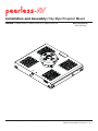
Installation and Assembly: Tray Style Projector Mount
Models: PSMU-PRS, PSMU-PRS-S, PSMU-PRS-W
Max Load Capacity:
30 lb (13.6 kg)
2300 White Oak Circle • Aurora, Il 60502 • (800) 865-2112 • Fax: (800) 359-6500 • www.peerlessmounts.com
ISSUED 08-09-06 SHEET #: 055-9470-5 11-21-11
NOTE: Read entire instruction sheet before you start installation and assembly.
WARNING
• Do not begin to install your Peerless product until you have read and understood the instructions and warnings
contained in this Installation Sheet. If you have any questions regarding any of the instructions or warnings, please
call Peerless customer service at 1-800-865-2112.
• This product should only be installed by someone of good mechanical aptitude, has experience with basic building
construction, and fully understands these instructions.
• Make sure that the supporting surface will safely support the combined load of the equipment and all attached
hardware and components.
• Never exceed the Maximum Load Capacity of 30 lb (13.6 kg).
• If mounting to wood ceiling joists, make sure that mounting screws are anchored into the center of the joists. Use of
an "edge to edge" stud finder is highly recommended.
• Always use an assistant or mechanical lifting equipment to safely lift and position equipment.
• Tighten screws firmly, but do not overtighten. Overtightening can damage the items, greatly reducing their holding
power.
Accessories
•
•
•
•
•
•
•
•
•
•
Lightweight Adjustable Suspended Ceiling Kit (CMJ 500)
Lightweight Suspended Ceiling Kit (CMJ 455)
Accessory Pack for CMJ 455 (ACC 455)
Lightweight Cathedral Ceiling Plate (ACC 912)
Unistrut or Structural Ceiling Plates (CMJ 300, CMJ 310)
Anti-Vibration Ceiling Plates (ACC 845)
•
•
•
•
Round Ceiling Plate (ACC 570)
Cord Wrap (ACC 852, ACC 852W, ACC 852S)
3/4" Pipe Reducer (ACC 913)
Fixed Length 1 1/2" Extension Columns
(EXT models)
• Adjustable Length 1 1/2" Extension Columns
(ADJ models)
I-Beam Clamps (ACC 558, ACC 559)
•
•
•
•
Truss Ceiling Adapter (ACC 557)
Unistrut Adapter (ACC 550)
Escutcheon Ring (ACC 640)
Extension Column Stabilizer Kit (ACC 050)
Extension Column Connector (ACC 109)
1/2" Threaded Rod (ACC 820)
Threaded Rod Adapter (ACC 810)
Tools Needed for Assembly
• stud finder ("edge to edge" stud finder is recommended)
• phillips screwdriver
• drill with 5/16", 3/8", and 5/32" drill bits
IMPORTANT! Turn to the appropriate page for your ceiling installation.
Installations:
To Wood Joist Finished Ceilings,
Exposed Wood Joists, or Wood Beam Ceilings ......................................................................................... page 5
To Concrete Ceilings ..................................................................................................................................... page 6
To Threaded Rod, or Extension Columns.................................................................................................... page 7
Projector Alignment:
Adjusting Roll Pitch and Yaw ..................................................................................................................... page 11
2 of 11
ISSUED 08-09-06 SHEET #: 055-9470-5 11-21-11
IMPORTANT! Read entire instruction sheet before you start installation and assembly.
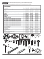
Before you start check the parts list below to make sure all of the parts shown are included.
Parts List
A
B
C
D
E
F
G
H
I
J
K
L
M
N
O
P
Q
R
S
T
U
V
W
X
Y
Z
Description
projector mount assembly
tray
lock plug
thumb screw
#10-32 X 3/8 serrated washer head socket pin screw
spacer
bushing
square nut
washer
1/4 X 3/8 socket pin
M3 X 16mm serrated washer head socket pin screw
M3 X 25mm serrated washer head socket pin screw
M4 X 16mm serrated washer head socket pin screw
M4 X 25mm serrated washer head socket pin screw
M4 X 35mm serrated washer head socket pin screw
M5 X 16mm serrated washer head socket pin screw
M5 X 25mm serrated washer head socket pin screw
M6 X 20mm serrated washer head socket pin screw
M6 X 30mm serrated washer head socket pin screw
4 mm T-WRENCH
2mm allen wrench
wood screw
concrete anchor
key
#10-32 X 1/4" socket pin screw
connection block
Qty.
1
1
1
1
2
12
4
4
4
4
4
4
4
4
4
4
4
4
4
1
1
2
2
1
1
1
PSMU-PRS
054-1174
055-0725
3022-502
560-0106
520-1151
540-9416
590-1116
530-1022
540-1025
520-1109
510-1083
510-1127
510-1087
510 1082
510-1082
510-1097
510-1161
510-1122
510-9554
510-1067
560-1718
560-1097
5S1-015-C03
590-0320
0000-322
520-1196
580-1065
PSMU-PRS-S
054-4174
055-0725-S
3022-502
560-0106
520-2151
540-9416
590-1116
530-1022
540-1025
520-1109
510-1083
510-1127
510-1087
510 1082
510-1082
510-1097
510-1161
510-1122
510-9554
510-1067
560-1718
560-1097
5S1-015-C04
590-0320
0000-322
520-2196
580-4065
PSMU-PRS-W
054-2174
055-0725-W
3022-502
560-0106
520-2151
540-9416
590-1116
530-1022
540-1025
520-1109
510-1083
510-1127
510-1087
510 1082
510-1082
510-1097
510-1161
510-1122
510-9554
510-1067
560-1718
560-1097
5S1-015-C04
590-0320
0000-322
520-2196
580-4065
C
D
A
I
H
U
T
V
B
E
F
Q
R
G
NOTE: Assembled to tray assembly (B)
J
K
L
M
P
N
O
S
Y Z
X
NOTE: Actual parts may appear slightly different than illustrated.
W
3 of 11
ISSUED 08-09-06 SHEET #: 055-9470-5 11-21-11
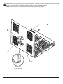
1
Remove the lock plug (C) by turning the key counterclockwise. Open the top cover and attach connection block (Z)
to tray (B) using two #10-32 x 3/8" serrated washer head socket pin screws (E) as shown.
NOTE: Make sure that the connection block shoulder is facing the back of projector.
E
B
Z
BACK OF
PROJECTOR
CONNECTION
BLOCK SHOULDER
4 of 11
ISSUED 08-09-06 SHEET #: 055-9470-5 11-21-11
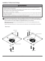
Installation To Wood Joist Ceilings
WARNING
• Installer must verify that the supporting surface will safely support the combined load of the equipment and all
attached hardware and components.
• Tighten wood screws so that projector mount assembly is firmly attached, but do not overtighten. Overtightening
can damage the screws, greatly reducing their holding power.
• Never tighten in excess of 80 in. • lb (9 N.M.).
• Make sure that mounting screws are anchored into the center of the stud. The use of an "edge to edge" stud finder
is highly recommended.
• Hardware provided is for attachment of mount through standard thickness drywall or plaster into wood studs. Installers are responsible to provide hardware for other types of mounting situations.
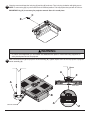
2
Place projector mount assembly (A) on ceiling as a template and mark the center of the two mounting holes. Make
sure that the mounting holes are in the center of the wood joist. Drill two 5/32" (4 mm) dia. holes to a minimum
depth of 2.5" (64 mm). Attach projector mount assembly (A) with two #14 X 2.5" (6 mm x 64 mm) wood screws (V)
and two flat washers (I) as shown in figure 2.1 or figure 2.2 depending on joist orientation.
Note: Mounting slots on projector mount assembly (A) allow for 30° (±15°) of swivel adjustment before fully
securing wood screws (V).
Tighten wood screws (V) using 3/8" (10 mm) socket wrench until projector mount assembly (A) is firmly attached.
Skip to step 6
WOOD JOIST
WOOD JOIST
FRONT OF MOUNT
A
A
FRONT OF MOUNT
I
I
V
V
figure 2.2
figure 2.1
5 of 11
ISSUED 08-09-06 SHEET #: 055-9470-5 11-21-11
Installation to Concrete Ceilings
WARNING
• Concrete must be 2000 psi density minimum. Lighter density concrete may not hold concrete anchor.
• Make sure that the supporting surface will safely support the combined load of the equipment and all attached hardware and components.
Place projector mount assembly (A) on ceiling as a
template and mark the center of the two mounting
holes. Drill two 5/16" (8 mm) dia. holes to a minimum
depth of 2.5" (64 mm). Attach projector mount assembly
(A) using two concrete anchors (W), two flat washers
(I), and two #14 x 2.5" wood screws (V) as shown.
3
NOTE: Mounting slots on projector mount assembly
allow for 30° (±15°) of swivel adjustment before fully
securing wood screw.
Tighten wood screws (V) using 3/8" (10 mm) socket
wrench, phillips screwdriver until projector mount
assembly (A) is firmly attached.
W
FRONT OF
MOUNT
Skip to step 6
A
WARNING
I
• Tighten wood screws firmly, but do not overtighten.
Overtightening can damage screws, greatly reducing
their holding power.
V
• Never tighten in excess of 80 in. • lb (9 N.M.).
• Always attach concrete anchors directly to loadbearing concrete.
• Never attach concrete anchors to concrete covered
with plaster, drywall, or other finishing material. If
mounting to concrete surfaces covered with a finishing surface is unavoidable, the finishing surface
must be counterbored as shown below. Be sure concrete anchors do not pull away from concrete when
tightening screws. If plaster/drywall is thicker than
5/8", custom fasteners must be supplied by installer.
concrete
surface
1
W
Drill holes and insert anchors (W).
I
2
V
A
W
Place plate (A) over anchors (W) and secure with screws (V).
CUTAWAY VIEW
INCORRECT
concrete
A
plaster/
dry wall
CORRECT
3
concrete
A
plaster/
dry wall
Tighten all fasteners.
6 of 11
ISSUED 08-09-06 SHEET #: 055-9470-5 11-21-11
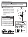
Installation to Threaded Rod
(Professional installation only)
4
Thread two 3/8-16 hex thin nylon-insert locknuts (not included) on two 3/8-16 threaded rods (not included) to the
desired height of projector mount assembly. Attach projector mount assembly (A) to two 3/8-16 threaded rods using
two 3/8-16 hex thin nylon-insert locknuts as shown in figure 4.1 or figure 4.2.
Skip to step 6.
3/8 -16 THREADED ROD
(NOT INCLUDED)
3/8 -16 THREADED ROD
(NOT INCLUDED)
3/8 -16 HEX THIN NYLONINSERT LOCKNUT
(NOT INCLUDED)
3/8 -16 HEX THIN NYLONINSERT LOCKNUT
(NOT INCLUDED)
FRONT OF
MOUNT
A
A
FRONT OF
MOUNT
3/8 -16 HEX THIN
NYLON-INSERT
LOCKNUT
(NOT INCLUDED)
3/8 -16 HEX THIN
NYLON-INSERT
LOCKNUT
(NOT INCLUDED)
fig. 4.1
fig. 4.2
Installation to Extension Column
5
Screw projector mount assembly (A) onto extension column (sold separately) as shown in figure 5.1. Tighten
swivel stop screw against extension column or reducer using 4 mm allen wrench (T).
NOTE: Swivel stop screw is used to jam against threads of extension column or reducer to prevent any excess
movement of projector mount assembly (A). Do not overtighten screw; overtightening screw will damage threads
making it difficult to separate products.
1 1/2" EXTENSION COLUMN
(SOLD SEPARATELY)
A
BACK OF MOUNT
SWIVEL STOP SCREW
fig. 5.1
7 of 11
ISSUED 08-09-06 SHEET #: 055-9470-5 11-21-11
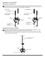
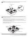
6
Open the mount and remove thumb screw (D) as shown. NOTE: The upper tray of the mount will now slide off
of the lower tray.
D
Installation of Projector
7
Flip projector upside down. Attach lower tray to the bottom of the projector using appropriate number of screws (K, L,
M, N, O, P, Q, R or S), washers (I) and spacers (F) as shown. Use 4 mm allen wrench (T) to tighten screws.
IMPORTANT: If projector does not have at least three mounting holes, do not use this tray assembly.
NOTE: Some projectors have feet which can be removed and the corresponding threaded insert can be used for a
mounting hole.
NOTE: Projector may differ slightly in appearance.
K,L,M,N,
O,P,Q,R
or S
I
F
LOWER
TRAY
R
TO
C
JE
O
PR
8 of 11
ISSUED 08-09-06 SHEET #: 055-9470-5 11-21-11
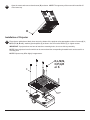
8
Slide upper tray into the lower tray as shown.
UPPER
TRAY
LOWER
TRAY
9
Attach thumb screw (D) to mount as shown to lock the upper tray to the lower tray.
UPPER
TRAY
LOWER
TRAY
D
9 of 11
ISSUED 08-09-06 SHEET #: 055-9470-5 11-21-11
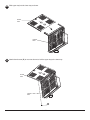
10
Close the mount and insert the lock plug (C) and key (X) as shown. Turn lock plug clockwise until tightly secure.
NOTE: To remove key (X), key slot must be in the horizontal position. This may require that you back off 1/4 turn.
IMPORTANT: Key (X) is neccesary for projector removal. Store it in a safe place.
C
X
WARNING
• Do not lift more weight than you can handle! Use additional man power or mechanical lifting equipment to
safely handle placement of the projector!
11
Slide connection block (Z) into projector mount assembly (A). Tighten captive screw to secure projector to projector
mount assembly (A).
A
Z
Z
A
BACK VIEW
OR
CT
E
OJ
B
PR
A
CAPTIVE SCREW
Z
10 of 11
ISSUED 08-09-06 SHEET #: 055-9470-5 11-21-11
12
IMPORTANT: For security installations, insert one #10-32 socket pin screw (Y) through projector mount assembly
(A) and into connection block (Z) as shown. Tighten screw with 4mm t-wrench (T).
A
Y
13
To adjust yaw (swivel) for wood stud, concrete ceiling, and threaded rod mounting applications: Loosen
wood screws (V), or locknuts for threaded rods, until projector mount can be rotated. Rotate mount to desired position and retighten screws or locknuts.
To adjust yaw (swivel) for extension column applications: Loosen screw on projector mount assembly (A) indicated below until projector mount can be rotated. Rotate mount to desired position and retighten screw.
To adjust pitch (forward and backward tilt): Loosen two screws on projector mount assembly (A) indicated below. Tilt mount to desired position and retighten screws.
To adjust roll (side to side tilt): Loosen two screws on projector mount assembly (A) indicated below. Tilt mount
to desired position and retighten screws.
SCREWS
FOR PITCH
ADJUSTMENT
SCREW FOR SWIVEL STOP
A
SCREWS FOR
ROLL ADJUSTMENT
BACK OF MOUNT
11 of 11
ISSUED 08-09-06 SHEET #: 055-9470-5 11-21-11
© 2011 Peerless Industries, Inc. All rights reserved.
Peerless is a registered trademark of Peerless Industries, Inc. Vertor Pro and Armor Lock are trademarks of Peerless Industries Inc.
All other brand and product names are trademarks or registered trademarks of their respective owners.