1
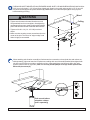
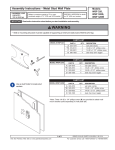
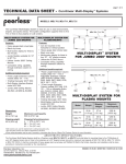
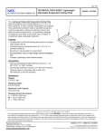
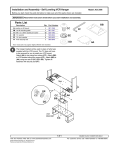
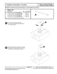
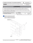
Installation and Assembly - Vibration Absorber Ceiling Mount for Structural
Ceiling
WARNING
IMPORTANT! Read entire instruction sheet
before you start installation and assembly.
• Installer must verify that the ceiling will safely support
four times the combined weight of all attached equipment and hardware.
Before you start check the parts list below to
make sure all of the parts shown are included.
Parts List
Description
A
B
C
D
E
F
G
H
anti- vibration mount
rubber bumper
plastic finishing caps
#14 x 2.5 wood screw
.26 x .7x .062 plastic washer
rubber grommet
M5 x .8 x 10 mm socket-pin screw
M5 x .8 x 10 mm phillips screw
Model:
ACC 840
Qty.
Part Number
1
4
2
2
2
1
1
1
055-0004
590-1124
590-1123
5S1-015-C03
540-9439
530-9401
520-1063
520-9250
B
A
C
E
H
G
F
D
Note: Actual parts may appear slightly different than illustrated.
WARNING
• If mounting to Unistrut®, purchase model ACC 845. Model ACC 840 should be mounted to wood only. If the antivibration mount is altered in any way it may not be as effective, or effective at all, in controlling vibration. In
addition, be certain that no part of the system, including any extension column that might be used, comes in
contact with the vibrating surface. If mounting through a drop ceiling, be sure to cut a large enough hole in the
ceiling tile as to avoid contact with the extension column. If using an escutcheon ring, be sure it does not come
in contact with the false ceiling. Also be sure to use the rubber bumper (B) provided.
1 of 4
Visit the Peerless Web Site at www.peerlessindustries.com
ISSUED:12-14-01 SHEET#: 055-9068-3 11-10-04
For customer service call 1-800-729-0307 or 708-865-8870.
Attach four rubber bumpers (B) to anti-vibration mount (A) as shown below.
B
A
Use stud finder to locate stud centers. Use anti-vibration mount (A) as a template to mark slot centers on
stud centers.
Ceiling
Wood stud
A
TOP VIEW
2 of 4
Visit the Peerless Web Site at www.peerlessindustries.com
ISSUED:12-14-01 SHEET#: 055-9068-3 11-10-04
For customer service call 1-800-729-0307 or 708-865-8870.
FOR WOOD JOIST FINISHED CEILING, EXPOSED WOOD JOISTS, OR WOOD BEAM CEILING ONLY drill four
5/32" (4 mm) dia. holes 2 1/2" (65 mm) deep. Attach anti-vibration mount (A) using two #14 x 2.5" (6 mm x 65
mm) wood screws (D) and two plastic washers (E). Note: Make sure rubber bumpers (B) are firmly in place
before attaching to ceiling.
Wood
WARNING
Ceiling
• Tighten wood screws so that anti-vibration mount is
firmly attached, but do not overtighten. Overtightening
can damage the screws, greatly reducing their holding
power and decrease the anti-vibrational effectiveness!
• Tighten to 30-40 in • lb (3.4 - 4.5 N.M.) maximum
torque.
• Make sure that mounting screws are anchored into the
center of the joist. The use of an "edge to edge" stud
finder is highly recommended.
A
E
D
When attaching anti-vibration mount (A) to flush mount tube or extension column (both tube and column are
sold separately), tighten at least four complete turns ending with one of the small threaded holes aligned with
slot in the end of flush mount tube or extension column. Insert and tighten one M5 screw (H) to lock tube
position (shown below on right side). Note: For security the M5 phillips screw (H) can be replaced with
M5 socket-pin screws (G).
H
or
A
G
flush mount tube or
extension column
(sold separately)
3 of 4
Visit the Peerless Web Site at www.peerlessindustries.com
ISSUED:12-14-01 SHEET#: 055-9068-3 11-10-04
For customer service call 1-800-729-0307 or 708-865-8870.
When attaching anti-vibration mount (A) to flush mount tube or extension
column (both tube and column are sold separately ), tighten at least four
complete turns ending with one of the small threaded holes aligned with slot
in the end of flush mount tube or extension column. Insert and tighten one
M5 screw (H) to lock tube position (shown below on right side). Note: For
security the M5 philips screw (H) can be replaced with M5 socket-pin
screws (G).
H
or
A
G
flush mount tube or
extension column
(sold sparately)
OPTIONAL: Place grommet (F) on antivibration mount (A) and place one finishing cap
(C) on other end of anti-vibration mount (A).
Route cords through extension column and out
cord management holes in anti-vibration mount
(A). Note: If using Vector Pro projector
mounts, you will need accessory ACC 800
to route cords through column.
Place one finishing cap (C) on each end of
anti-vibration mount (A).
C
F
4 of 4
Visit the Peerless Web Site at www.peerlessindustries.com
© 2004 Peerless Industries, Inc. All rights reserved.
Peerless is a registered trademark of Peerless Industries, Inc.
Unistrut® is a registered trademark of Peerless Industries, Inc.
C
ISSUED:12-14-01 SHEET#: 055-9068-3 11-10-04
For customer service call 1-800-729-0307 or 708-865-8870.