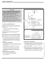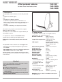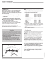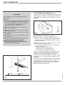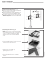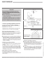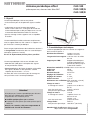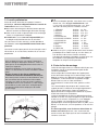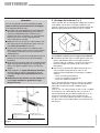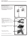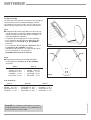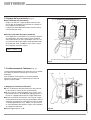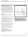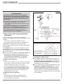
1
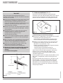
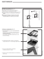
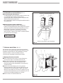
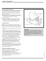
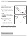
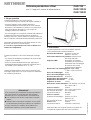
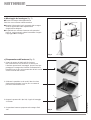
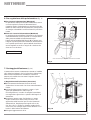
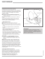
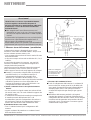
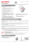
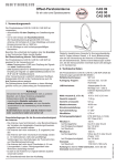
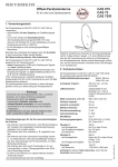
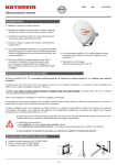
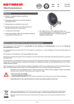
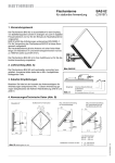
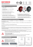
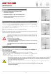
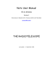
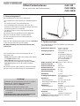
Offset-Parabolantenne
für ein, zwei oder drei Speisesysteme
CAS 120
CAS 120/G
CAS 120/R
1. Verwendungszweck
Beachten Sie unbedingt die Angaben über die Grenzlast
in den Technischen Daten (rechte Spalte).
Bei Überschreitung der Grenzwerte können Teile
losbrechen!
Die Parabolantenne CAS 120 ist geeignet für die
Verwendung mit
– einem Speisesystem (LNB) zum Empfang der Signale
von einem Satelliten oder
– zwei oder drei Speisesystemen für MultifeedAnwendungen zum Empfang der Signale von zwei
oder drei Satelliten mit 3°– 4° oder 6° Satellitenabstand.
Die Speisesysteme sowie Hinweise zu deren Montage
gehören nicht zum Lieferumfang der Parabolantenne.
Achtung!
Verwenden Sie die Parabolantenne nicht zu anderen
Zwecken, als in dieser Anleitung angegeben.
Insbesondere dürfen Sie niemals
● irgendwelche Bauteile verändern oder
● andere Bauteile verwenden, als vom Hersteller
ausdrücklich für die Verwendung mit der Antenne
vorgesehen.
Andernfalls kann es sein, dass die Antenne nicht
mehr ausreichend stabil und sicher ist !
Abb. 1
2. Technische Daten
Die Parabolantenne CAS 120 erfüllt die Anforderungen
gemäß EN 50083-1.
Reflektordurchmesser:
Breite: 1 234 mm
Höhe: 1 335 mm
Auslegung Tragarm:
1 160 mm max. von der
Rohrmitte
LNB-Aufnahme:
Schwenkbare Haltevorrichtung für die Adapterplatte zur Montage von
bis zu drei KathreinSpeisesystemen
Maße verpackt (L x B x H): 1 500 x 1 335 x 225 mm
Gewicht verpackt:
29 kg
Gewicht unverpackt:
18,5 kg
Mastdurchmesser:
50–90 mm
Elevationseinstellung:
5°–50°
Azimuteinstellung:
0°–360°
Windfläche:
1,35 m2
Schwingungsfestigkeit:
ETS 300019-2-4 (12.94)
IEC Class 4 M 5
Windlast 1:
1 296 N
bei Montagehöhe:
bis 20 m über Grund
bei Windgeschwindigkeit: bis 130 km/h
bei Staudruck:
800 N/m2
Windlast 2:
1 776 N
bei Montagehöhe:
höher als 20 m über Grund
(Faktor 1,37)
bei Windgeschwindigkeit: bis 150 km/h
Grenzlast
2 646 N
bei Staudruck:
1 900 N/m2 (190 km/h)
Achtung! Es können Teile losbrechen, wenn die
Grenzlast überschritten wird!
936.2079/A/0206/1.8d
Die Parabolantenne CAS 120 ist vorgesehen:
– Ausschließlich für den Empfang von Satellitensignalen
und
– nur für den Einsatz als Haushaltsantenne.
Als Haushaltsantenne gilt gemäß DIN 4131 eine
Antenne mit höchstens 6 m freier Mastlänge und einem
Einspannmoment bis zu 1650 Nm.
– Für die Montage an nicht schwingungsanfälligen
Bauwerken.
Die Antenne darf nur gemeinsam mit der Halterung
ZAS 120, Bestell-Nr. 218672, montiert werden.
Die ZAS 120 gehört nicht zum Lieferumfang der
Parabolantenne.
3. Bevor Sie…
…die Parabolantenne montieren, anschließen oder
verwenden, beachten Sie unbedingt die Hinweise in dieser Anleitung! Wenn Sie die Hinweise nicht beachten,
können durch Fehler bei der Montage oder beim
Anschluss Schäden an der Antenne oder am
Montageort entstehen,
können durch Fehlverhalten Gefahren für Ihre
Gesundheit und Ihr Leben entstehen,
haftet der Hersteller nicht für darauf zurückzuführende
Fehlfunktionen und Schäden!
Beachten Sie bei Arbeiten an Antennenanlagen auf Ihre
Verantwortung Mitmenschen gegenüber!
Heben Sie diese Anleitung für später auftretende Fragen
auf und geben Sie diese bei einem Verkauf an den neuen
Besitzer weiter!
Vorsicht!
Auf keinen Fall dürfen Sie unter Freileitungen
Antennen montieren, andernfalls können vielleicht
unbedingt erforderliche Mindestabstände unterschritten sein.
Halten Sie auch zu den Seiten mindestens 1 m
Abstand zu allen anderen elektrischen Einrichtungen
ein!
Es besteht Lebensgefahr, falls Sie oder metallische
Antennenteile elektrische Einrichtungen berühren!
Montieren Sie niemals Antennen auf Gebäuden mit
leicht entzündbaren Dachabdeckungen, wie z. B.
Stroh, Reet oder ähnlichen Materialien!
Andernfalls besteht Brandgefahr bei atmosphärischen
Überspannungen (statische Aufladung) oder
Blitzentladungen (z. B. Gewitter).
Abb. 2
Für einen einwandfreien Empfang muss eine freie
„Sicht“ in Richtung Süden (+/- 20°) gewährleistet
sein, bei einer Erhebung von etwa 30°. Dann stehen
Ihnen folgende Satelliten zur Auswahl:
1 TÜRKSAT
Position 42° Ost
2 ASTRA 2
Position 28,2° Ost
3 ASTRA 3
Position 23,5° Ost
4 ASTRA 1
Position 19,2 Ost
5 EUTELSAT W2
Position 16° Ost
6 EUTELSAT HOTBIRD Position 13° Ost
7 EUTELSAT W1
Position 10° Ost
8 EUTELSAT W3
Position 7° Ost
9 Thor
Position 1° West
10 Telecom
Position 5° West
11 HISPA-Sat
Position 30° West
Achten Sie darauf, dass sich keine Hindernisse
zwischen der Parabolantenne und dem jeweiligen
Satelliten befinden (z. B. Bäume, Dach- oder
Hausecken, andere Antennen).
Diese können den Empfang so beeinträchtigen, dass
dieser bei ungünstiger Witterungslage völlig ausfällt.
4. Montageort wählen
Der richtige Montageort ist entscheidend dafür, ob Ihre
Parabolantenne sicher aufgebaut und optimal
funktionieren kann.
Bei der Montageortwahl sind bauwerkstypische
Besonderheiten zu berücksichtigen. Bei Montage an
Dach- und Gebäudekanten und zylindrischen Bauwerken
ist gemäß DIN 1055, Teil 4 bzw. 4131, mit erhöhten
Wind- oder Schwingungsbelastungen zu rechnen.
Die dynamischen Eigenschaften der Antenne und des
Bauwerks können sich gegenseitig beeinflussen und
negativ verändern.
Bei Nichtbeachtung kann eine Überschreitung der unter
Punkt 2 genannten Grenzbelastung oder
Schwingungsfestigkeit auftreten.
Die Parabolantenne muss nicht unbedingt auf das Dach,
weil es nicht auf die Höhe über Grund ankommt,
sondern nur auf die freie „Sicht“ zum Satelliten. Deshalb
kann ein geeigneter Montageort zum Beispiel auch im
Garten, auf dem Balkon, auf der Terrasse, an einer
Fassade oder an einer Garage zu finden sein.
Abb. 2
936.2079/A/0206/2.8d
Wenn also möglich, sollten Sie besser nicht auf dem
Dach montieren. Sie verringern damit Ihren Arbeitsaufwand und die Gefahren bei Montagearbeiten auf dem
Dach!
Vorsicht!
Bei der Montage der Parabolantenne können
Gefahren für Ihr Leben und Ihre Gesundheit entstehen!
Beachten Sie deshalb:
5. Antenne montieren (Abb. 4)
Achten Sie bei der Montage des Antennenträgers
(Standfuß, Mast oder Wandausleger) darauf, dass dieser
senkrecht steht. Andernfalls kann die Ausrichtung der
Antenne auf den Satelliten zu Schwierigkeiten führen.
Die hier beschriebenen Montageschritte setzen gute
handwerkliche Fähigkeiten und Kenntnisse vom
Materialverhalten bei Windeinwirkung voraus.
Lassen Sie die Arbeiten daher von einem Fachmann
ausführen, wenn Sie nicht selbst über solche
Voraussetzungen verfügen.
Betreten Sie Dächer oder absturzgefährdete Stellen
nur mit einem ordnungsgemäß angelegten intakten
Sicherheitsgurt!
Leitern oder andere Steighilfen müssen in einwandfreiem Zustand sein. Bauen Sie keine waghalsigen
„Klettertürme“!
Wenn Passanten durch herabfallende Gegenstände
während der Montage gefährdet werden können,
müssen Sie den Gefahrenbereich absperren!
Achten Sie auf Freileitungen, falls solche in der
Nähe des Montageortes vorbeiführen.
Bei Berührung besteht akute Lebensgefahr!
Arbeiten Sie niemals bei aufziehendem Gewitter
oder während eines Gewitters an Antennenanlagen.
Es besteht Lebensgefahr!
Abb. 3
Abb. 4
a) Anforderungen an den Antennenträger
Verwenden Sie nur Träger oder Tragrohre, die speziell
für Antennenmontage geeignet sind.
Andere Träger oder Rohre erfüllen möglicherweise
nicht die erforderlichen Belastungsanforderungen.
Wählen Sie für die Befestigung der Antennen Rohre
mit einem Durchmesser von 60–90 mm und einer
Wanddicke von mindestens 2 mm.
Kathrein empfiehlt für die Montage folgende Bauteile:
– Ebenerdig: Standfuß ZAS 15
– Wandmontage: Wandhalterung ZAS 16
– Dachmontage: Mastrohr ZAS 03 oder ZAS 04
Falls Sie doch auf dem Dach montieren, müssen Sie
beachten, dass, entsprechend EN 50083-1, das
zulässige Moment an der Einspannstellte maximal
1 650 Nm betragen darf.
Daraus ergeben sich für die beiden Windlastfälle 1 und 2
die in Abb. 3 aufgeführten maximal zulässigen Mastlängen.
Bei Überschreitung des Moments von 1 650 Nm an der
Einspannstelle, z. B. durch einen längeren Mast und
noch zusätzliche montierte Antennen, muss gemäß
EN 50083-1 für die Gewährleistung der Sicherheit der
baulichen Anlage und/oder des Gebäudes ein Statiker
hinzugezogen werden.
936.2079/A/0206/3.8d
Vergewissern Sie sich, ob das Dach Ihr Gewicht
aushält. Betreten Sie niemals brüchige oder
unstabile Flächen! Tragen Sie feste,
rutschhemmende Schuhe!
b) Halterung montieren (Abb. 5)
Befestigen Sie die Azimut-/Elevationshalterung
ZAS 120 wie aus der Abbildung ersichtlich.
W
Weitere Hinweise zur Montage der Halterung ZAS 120
entnehmen Sie dem dort beiliegenden Anwendungshinweis.
Falls Sie beabsichtigen, die Antenne nicht auf der
Mastspitze zu montieren, müssen Sie vorher den
Auflagewinkel W von der Halterung abschrauben.
Abb. 5
c) Antenne vorbereiten (Abb. 6)
1. Die vier Schrauben aus den Sicherungsholzleisten
herausdrehen.
Entfernen Sie für die weiteren Montageschritte die
Kartonhülle noch nicht. Sie dient zum Schutz der
Speisesystemhalterung.
Den Ausleger soweit herausschwenken bis er am
Kartonrand aufliegt.
2. Parabolspiegel anheben. Dadurch schwenkt der
Ausleger weiter, bis er in die Verriegelung V einrastet.
S
V
3. Die vier Schrauben S (SW 19) anziehen.
Anziehdrehmoment 37–43 Nm.
Abb. 6
936.2079/A/0206/4.8d
4. Hängen Sie die vorbereitete Antenne in die Halterung
ZAS 120 ein.
d) Speisesystem (LNB)
Die Speisesysteme sowie Hinweise zu deren Montage
gehören nicht zum Lieferumfang der Parabolantenne.
Entnehmen Sie daher die näheren Informationen zur
sachgerechten Montage den Anleitungen, die dem
jeweiligen Speisesystem beiliegen.
Abb. 7
An der schwenkbaren Haltevorrichtung am Tragarm
können über die Adapterplatte ein, zwei oder drei
Kathrein-Speisesystem montiert werden. Auf der
Adapterplatte zeigen die Markierungen
– 3 die Montageposition für ein Speisesystem,
– 2 und 4 die Montageposition für zwei Speisesysteme
(Multifeed) bei 3°– 4° Satellitenabstand,
– 1 und 5 die Montageposition für zwei
Speisesysteme (Multifeed) bei 6° Satellitenabstand.
Bei Belegung der Positionen 1 und 5 kann auch
zusätzlich mittig auf Position 3 ein Speisesystem
montiert werden (3 Satelliten mit jeweils 3° Abstand)
Abb. 7
Satellit
A
Satellit
B
Abb. 8
Beispiel für Montagepositionen bei MultifeedAnwendung mit 3°-4° Satellitenabstand.
Pos. 2
ASTRA 19,2° Ost
ASTRA 23,5° Ost
EUTELSAT 16° Ost
HOTBIRD 13° Ost
EUTELSAT 10° Ost
+
+
+
+
+
Pos. 4
EUTELSAT 16° Ost
ASTRA 19,2° Ost
HOTBIRD 13° Ost
EUTELSAT 10° Ost
EUTELSAT 7° Ost
B A
Abb. 8
mit 6° Satellitenabstand.
+
+
+
+
(Pos. 3)
(ASTRA 19,2° Ost)
(EUTELSAT 16° Ost)
(HOTBIRD 13° Ost)
(EUTELSAT 10° Ost)
+
+
+
+
Pos. 5
EUTELSAT 16° Ost
HOTBIRD 13° Ost
EUTELSAT 10° Ost
EUTELSAT 7° Ost
Tipp! Bei Multifeed-Anwendungen sollte die Antenne
auf den Satelliten ausgerichtet werden, der die pegelschwächsten Signale sendet.
936.2079/A/0206/5.8d
Pos. 1
ASTRA 23,5° Ost
ASTRA 19,2° Ost
EUTELSAT 16° Ost
HOTBIRD 13° Ost
6. Polarisationsvoreinstellung (Abb. 9)
Ein Speisesystem (Monofeed)
In Abhängigkeit Ihres Standortes und der Position des
zu empfangenden Satelliten stellen Sie am
Speisesystem den Polarisationswinkel entsprechend
Tabelle (siehe Speisesystem) ein.
Die schwenkbare Haltevorrichtung H verbleibt dabei in
der Nullposition.
Mehrere Speisesysteme (Multifeed)
Bei Multifeed-Anordnung ist die schwenkbare
Haltevorrichtung H entsprechend beiliegender Azimut/Elevationstabelle für Multifeed-Anwendung um den
Winkel V zu schwenken. In diesem Falle ist der
Polarisationswinkel am Speisesystem nicht nach
dieser Tabelle, sondern nach einem zu berechnenden
Korrekturwinkel einzustellen:
PWNEU = PWTAB - V
Abb. 9
7. Antenne ausrichten (Abb. 10)
Die Antenne muss sowohl von der Richtung (Azimut),
als auch von der Neigung (Elevation) her genau auf den
Satelliten ausgerichtet sein. Bei Multifeed-Lösungen
sollte die Antenne auf den Satelliten mit dem
schwächsten Signalpegel ausgerichtet werden.
a) Neigung (Elevation) einstellen
Beim Schwenken der Antenne um die Elelvationsachse müssen die 6 Schrauben A locker sein.
Stellen Sie nun die Neigung ein. Den genauen
Elevationswinkel für Ihren Standort finden Sie in der
Anleitung für das Speisesystem. Stellen Sie diesen
Winkel an der Skala (10° bis 50°) ein. Dabei muss der
entsprechende Skalenstrich auf der Halterung mit der
Kante C des Reflektorhaltebleches fluchten.
Ziehen Sie die Schrauben A leicht an.
Abb. 10
936.2079/A/0206/6.8d
Wenn Sie die Antenne per Hand leicht ankippen,
können Sie zum Grob- oder Voreinstellen des
Elevationswinkels die Mutter B (für Feineinstellung)
schneller drehen.
b) Richtung (Azimut) einstellen
Für die folgenden Schritte benötigen Sie gegebenenfalls
einen Helfer, falls Sie nicht selbst an einem AntennenMessgerät oder Bildschirm mit angeschlossenem
Satelliten-Receiver das Ergebnis der Ausrichtarbeiten
beobachten können.
Stellen Sie am Satelliten-Receiver einen bekannten
Programmplatz ein, um kontrollieren zu können, ob Sie
auch wirklich den gewünschten Satelliten
”getroffen” haben.
Drehen Sie die Antenne grob in Richtung Süden.
Drehen Sie danach die Antenne langsam um die
Mastachse – nach links und rechts, bis das eingestellte Programm am besten zu empfangen ist.
c) Feineinstellung
Lösen Sie die Schrauben A der Elevationsfixierung.
Schwenken Sie die Antenne leicht nach oben und
nach unten durch Drehen der Feineinstellmutter B, bis
Sie
– entweder am Antennen-Messgerät das stärkste Signal
messen
– oder bei optischer Beurteilung am Bildschirm den
besten Bildeindruck erzielen (nur bei Analogempfang):
Hierzu schwenken Sie die Antenne soweit nach oben
und unten, bis Sie jeweils an die Grenze kommen, wo
die ersten sogenannten „Fischchen“ (Spikes) am
Bildschirm erscheinen. Stellen Sie die Antenne dann in
die Mitte zwischen diesen beiden Grenzpunkten.
Achtung!
Kontrollieren Sie nach außergewöhnlichen
Belastungen (schweren Stürmen, ungewöhnlich starke Vereisung, außergewöhnlichen
Vorkommnissen) den Befestigungszustand
der Antenne.
d) Antenne endgültig festschrauben
Ziehen Sie am Ende alle Schraubverbindungen fest.
Kontrollieren Sie zum Schluss noch einmal alle
Schraubverbindungen auf festen Sitz.
Die Antennenkabel sind an solchen Stellen mit
Kabelbindern zu befestigen, wo die Gefahr besteht, dass
sie durch Windbewegungen scheuern und dadurch
beschädigt werden können.
936.2079/A/0206/7.8d
Korrigieren Sie nun abwechselnd die Richtung
(Azimut) und Neigung (Elevation), bis sich das Messoder Bildergebnis nicht mehr verbessert.
Hinweis: Beim Festdrehen der Flügelmuttern an den
zwei Schließschellen der Halterung kann sich die
Antenne leicht verdrehen! Dies sollten Sie bei der
Feineinstellung beachten (und eventuell für eine ganz
genaue Einstellung ausnutzen).
Gegebenenfalls optimieren Sie am Ende nochmals den
(die) Polarisationswinkel des (der) Speisesystem(e)s und
den Winkel der schwenkbaren Haltevorrichtung zur
Speisesystembefestigung.
Warnung!
Erdungs- und Blitzschutzarbeiten dürfen wegen
der Gefahr unzulänglicher Arbeitsergebnisse nur
von hierfür speziell geschulten Fachkräften des
Elektrohandwerks ausgeführt werden!
Potenzialausgleichsschiene
Netzanschluss
230 V
Erdungsleitung
Potenzialausgleichleitung
7. Antenne erden/Blitzschutz
Deshalb müssen der Mast und die Außenleiter der
Antennenkabel auf kürzestem Weg senkrecht über
einen geeigneten Erdungsleiter mit der Blitzschutzanlage des Gebäudes verbunden sein (falls keine
Blitzschutzanlage vorhanden ist: mit der Gebäudeerdung).
a) Geeignet als Erdungsleiter
– ist ein Einzelmassivdraht mit einem Querschnitt von
min. 16 mm2 Kupfer, min. 25 mm2 Aluminium oder min.
50 mm2 Stahl
– oder metallische Hausinstallationen (z. B. durchgehende Metallrohre der Wasser- oder Heizungsanlage), sofern diese vom Querschnitt und der
Dauerhaftigkeit der elektrischen Verbindung her
mindestens den Anforderungen an Erdungsleiter
entsprechen.
b) Nicht geeignet als Erdungsleiter
– sind die Außenleiter der Antennenkabel
– oder Schutzleiter oder Neutralleiter des
Starkstromnetztes.
Potenzialausgleichsschiene
Erdungsanschluss
Im schraffierten Bereich
ist lt. Norm eine
Antennenerdung nicht
zwingend erforderlich.
c) Führung von Erdungsleitern
Antennenkabel und Erdungsleiter dürfen nicht durch
Räume geführt werden, die zur Lagerung von leicht
entzündlichen Stoffen dienen (z. B. Heu, Stroh) oder in
denen sich eine explosive Atmosphäre bilden kann
(z. B. Gase, Dämpfe).
Bei Verwendung der Parabolantenne in kompletten
Antennenanlagen (z. B. Verteilanlagen) müssen zudem
die Erdungsmaßnahmen so ausgeführt sein, dass der
Erdungsschutz auch dann bestehen bleibt, wenn einzelne Einheiten entfernt oder ausgetauscht werden.
KATHREIN-Werke KG · Anton-Kathrein-Straße 1–3 · Postfach 10 04 44 · D-83004 Rosenheim · Deutschland · Telefon (0 80 31) 18 40 · Telefax (0 80 31) 18 43 06
Technische Änderungen vorbehalten.
Die Antenne muss geerdet werden, so fordert es die
EN 50083-1. Hiervon ausgenommen sind nur solche
Außenantennen,
– die mehr als 2 m unterhalb der Dachkante
– und zugleich weniger als 1,5 m von Gebäuden
angebracht sind.
Ungeachtet dessen empfiehlt Kathrein generell aus
Sicherheitsgründen einen Potenzialausgleich
vorzunehmen.
Gefahren können nicht nur durch Gewitter entstehen
(Blitzschlag), sondern auch durch statische Aufladung
oder Kurzschluss in den angeschlossenen Geräten:
Potenzialausgleichleitung
936.2079/A/0206/8.8d/SKS
Führen Sie niemals Erdungs- und Blitzschutzarbeiten durch, wenn Sie nicht selbst Fachkraft mit
entsprechenden Kenntnissen sind!
Die hier abgedruckten Hinweise sind keine Aufforderung an Nichtfachleute, Erdungs- und
Blitzschutzarbeiten in eigener Verantwortung durchzuführen, sondern dienen der von Ihnen beauftragten
Fachkraft als zusätzliche Information!
Offset parabolic antenna
for one, two or three feed systems
CAS 120
CAS 120/G
CAS 120/R
1. Intended use
The parabolic antenna CAS 120 is exclusively destined
for:
– reception of satellite signals
and
– utilisation as a domestic antenna.
A domestic or private antenna is defined acc. to
DIN 4131 as an antenna with a free mast length of 6 m
and a bending moment at the fixing point of up to
1650 Nm.
– installation on buildings not subject to oscillations.
The ZAS 120 is not included in the scope of delivery of
the parabolic antenna.
It is important to observe the maximum load as
mentioned in the technical data (right column).
If that value is exceeded, antenna parts can break
loose!
The parabolic antenna CAS 120 can be equipped with
– one feed system (LNB) for reception of signals from
one satellite.
– two or three feed systems for multifeed reception from
two or three satellites 3°– 4° or 6° apart.
Neither the feed systems nor the mounting instructions
for the feed systems are included in the scope of delivery
of the antenna.
Attention!
Do not use the parabolic antenna for purposes other
than mentioned in these instructions.
Never
● modify any antenna parts or
● use different components than those specifically
recommended by the manufacturer for use with
these antennas.
As a result of that, the stability and security of the
antenna can be affected.
Fig. 1
2. Technical data
The parabolic antennas CAS 120 complies with the
specifications acc. to DIN EN 50083-1.
Diameter of reflector:
Width: 1234 mm
Height: 1335 mm
Length of the support arm: 1160 mm max. from
centre of mast
LNB support:
Swivelling support for the
adapter plate for mounting
up to 3 Kathrein feed
systems
Measurements (packed):
1500 x 1335 x 225 mm
Weight (packed):
29 kg
Weight (unpacked):
18.5 kg
Diameter of mast:
50-90 mm
Elevation angle:
5°-50°
Azimuth angle:
0°-360°
Wind surface area:
1.35 m2
Vibration immunity:
ETS 300019-2-4 (12.94)
IEC Class 4 M 5
Windload 1:
1296 N
for an installation height:
up to 20 m above ground
for a wind velocity:
up to 130 km/h
at a dynamic pressure:
800 N/m2
Windload 2:
1776 N
for an installation height:
higher than 20 m above
ground (factor 1.37)
for a wind velocity:
up to 150 km/h
Maximum load:
2646 N
at a dynamic pressure:
1900 N/m2 (190 km/h)
Attention! If the max. load is exceeded, antenna parts
can break loose!
936.2079/A/0206/1.8e
The antenna may only be mounted with the support
ZAS 120, order. no 218672.
3. Before you…
begin to install, connect or utilise the parabolic antenna,
observe the information you find in these mounting
instructions. If you fail to pay attention to the information,
one cannot exclude
that due to wrong installation and connecting, or because of having modified components or using other
components, the antenna or the mounting place will
be damaged.
that because of inappropriate behaviour, risks for your
and other people's health and life will be created.
that the manufacturer will decline the liability for faulty
function and resulted damages.
It is most important that you are aware of the
responsibility you have for your own and other people's
safety when working on the antenna system!
Retain these instructions for possible later use
when questions come up. In case you sell the antenna,
pass the instructions on to the new owner.
Position
Position
Position
Position
Position
Position
Position
Position
Position
Position
Position
42° East
28.2° East
23.5° East
19.2° East
16° East
13° East
10° East
7° East
1° West
5° West
30° West
Unobstructed "visibility" means that there must be no
obstacles (such as trees, buildings, roofs, balconies or
similar obstacles) between the antenna and the
satellite.
Obstacles of this kind can impair the reception or even
make reception impossible.
South
West
The selection of the right mounting site for your antenna
is important in order to ensure safe and satisfactory
operation.
When choosing the mounting site, pay attention to
typical characteristics of the building. If the antenna is
installed on the edge of a roof or building, one must
reckon acc. to DIN 1055, Part 4 or 4131 with a higher
wind or oscillation load. This means that the dynamic
characteristics of the antenna and the building can
influence each other and change the characteristics
negatively. Disregard of these circumstances can lead to
exceeding the max. load or dynamic strength mentioned
in sect. 2.
It is not essential to mount the parabolic antenna on the
roof since it is not height above ground that matters but
an unimpeded line-of-sight to the satellite. Thus a
suitable mounting location may be found in the garden,
on the balcony/terrace or on a facade or garage, for
example.
Thus, if at all possible, the roof should be avoided as a
mounting location. In any event this reduces the amount
of work and avoids the dangers of doing installation
work on the roof!
936.2079/A/0206/2.8e
Never install the antenna below overhead power lines.
It can be that the required safety distance is not kept.
Furthermore, make sure that the lateral distance to all
other electrical systems is at least 1 m.
Danger to life exists if you or the antenna make
contact with live parts!
Do not install the antenna on buildings with easily
inflammable roofs (straw, reed or similar material).
This is a fire hazard since the antenna is subject to
static charge and lightning.
Fig. 2
1 TÜRKSAT
2 ASTRA 2
3 ASTRA 3
4 ASTRA 1
5 EUTELSAT W2
6 EUTELSAT HOTBIRD
7 EUTELSAT W1
8 EUTELSAT W3
9 Thor
10Telecom
11 HISPA-Sat
4. Mounting site
Attention!
East
Fig. 2
For good reception the antenna must have an unobstructed "visibility" to the south (+/-20). The horizontal
elevation angle must be 30°. The reception of the following satellites will then be possible:
5. Installation of the antenna (Fig. 4)
Attention!
The installation work can create dangers for your
health and life.
Therefore:
Make sure that the antenna support (foot mount, mast or
wall bracket) is installed in a vertical position, otherwise
the alignment of the antenna to the satellite can create
problems.
The mounting procedure described here demands
skills and a knowledge how the antenna behaves
when being subjected to atmospheric conditions.
If you do not have the required skills, ask a
specialist to do the installation work.
When working on the roof or near to drop away
sites, use a safety belt.
Make sure that the roof will support your weight.
Wear non-slip shoes!
Use ladders or other climbing aids that are in perfect condition.
If passers-by can be hurt by falling objects, block
the danger area.
Watch out for overhead power lines. Getting into
contact with these means danger to life!
Never work on the antenna during a
thunderstorm or when one is approaching.
This can put your life at risk!
Fig. 4
a) Requirements for the antenna support
Only use masts or supports specially suited to be
used as an antenna support. Other supports often do
not have the necessary strength required for the environmental conditions.
Choose a mast that has a diameter of 60-90 mm and
a wall thickness of at least 2 mm.
For mounting, Kathrein Werke KG recommends the
following components:
- Ground mounting: Tripod ZAS 15
- Wall mounting: Wall support ZAS 16
- Roof mounting: Mast ZAS 03 or ZAS 04
When mounting takes place on the roof, keep in mind
that the maximal admissible bending moment on the
fixing point is 1650 Nm according to EN 50083-1.
From this, the maximal admissible mast lengths, which
are listed in Fig. 3, are determined for windload 1 and
windload 2.
In the case of a greater bending moment than 1650 Nm
on the fixing point, for example, due to a longer mast
and additionally mounted antennas, a static engineer is
required to guarantee safety of the system and/or
building according to EN 50083-1.
Lmax
Fig. 3
Windload
up to 20 m above ground
Windload
(> 20 m above ground)
1.1 m
0.75 m
936.2079/A/0206/3.8e
Fixing point
b) Mounting the support arm (Fig. 5)
Installation on top of mast
Mount the azimuth/elevation support arm ZAS 120 on
the mast as shown in the drawing.
Installation in front of mast
W
Remove
Refer to the operating instructions supplied with the
ZAS 120 for more information regarding installation.
If you do not intend to mount the antenna on the top
of the mast, you must first remove the support angle
W from the support arm.
Fig. 5
c) Preparing the antenna (Fig. 6)
1. Remove the four screws from the protective strip of
wood.
For the following mounting steps, do not remove the
carton yet. It protects the feed system support.
Swing out the arm until it lies on the edge of the
carton.
2. Lift up the parabolic antenna. The arm continues to
swing out until it is fixed in the lock V.
S
V
3. Tighten the four screws S (SW 19).
Tightening torque 37-43 Nm.
Fig. 6
936.2079/A/0206/4.8e
4. Connect the prepared antenna to the support
ZAS 120.
d) Feed system (LNB)
The feed systems and their mounting instructions are not
in the scope of the delivery of the parabolic antenna.
Detailed information for the correct installation is
supplied together with each feed system.
Fig. 7
One, two or three Kathrein feed systems can be
mounted on the swivelling multifeed support on the
support arm via the adapter plate! The marking on the
adapter plate indicates
– 3 as the mounting position for one feed system,
– 2 and 4 as the mounting positions for two multifeed
systems allowing signal reception from satellites
3°-4° apart,
– 1 and 5 as the mounting positions for two multifeed
systems allowing signal reception from satellites
6° apart.
When using positions 1 and 5, a feed system can also
be additionally mounted in the middle on position 3
(3 satellites 3° apart).
Fig. 7
Satellite
A
Satellite
B
Fig. 8
Example for mounting positions for multifeed
reception with satellites 3°-4° apart.
Pos. 2
ASTRA 19,2° East
ASTRA 23,5° East
EUTELSAT 16° East
HOTBIRD 13° East
EUTELSAT 10° East
+
+
+
+
+
Pos. 4
EUTELSAT 16° East
ASTRA 19,2° East
HOTBIRD 13° East
EUTELSAT 10° East
EUTELSAT 7° East
B A
Fig. 8
with satellites 6° apart.
+
+
+
+
(Pos. 3)
(ASTRA 19,2° East)
(EUTELSAT 16° East)
(HOTBIRD 13° East)
(EUTELSAT 10° East)
+
+
+
+
Pos. 5
EUTELSAT 16° East
HOTBIRD 13° East
EUTELSAT 10° East
EUTELSAT 7° East
Tip! With multifeed applications the antenna should
be aligned to the satellite with the weaker signal level.
936.2079/A/0206/5.8e
Pos. 1
ASTRA 23,5° East
ASTRA 19,2° East
EUTELSAT 16° East
HOTBIRD 13° East
5. Setting polarisation angle (Fig. 9)
Sense of rotation for polarisation angle
One feed system (mono feed)
Adjust the polarisation angle according to the tables
(see feed system) on the feed system depending on
your mounting site and the position of the received
satellites.
The swivelling support H remains in the zero position.
Mounting several feed systems (multifeed)
For multifeed reception, the swivelling support H must
be moved to the angel V according to the supplied
azimuth/elevation table for multifeed reception. In this
case, the polarisation angle on the feed system is not
adjusted according to this table, but rather to the calculated correction angle :
PWNEW = PWTAB - V
Sense of rotation for the angle V for swivelling part
Fig. 9
7. Aligning the antenna (Fig. 10)
With regard to the direction (Azimuth) and the inclination
(Elevation), the antenna must be accurately aligned to
the satellite. For multifeed reception, it is necessary to
align the antenna to the satellite with the weaker signal
level.
a) Setting the inclination (Elevation)
When setting the elevation of the antenna, loosen the
6 screws A on the elevation scale.
Now set the elevation. You find the correct angle of
the elevation for your mounting site in the mounting
instructions supplied with the feed system. Set this
angle on the scale (10° to 50°). Here, the respective
scale line on the support must be aligned with the
edge C of the reflector support sheet.
Lightly screw on the screws A.
Fig. 10
936.2079/A/0206/6.8e
When you lightly tilt the antenna by hand, you can turn
the nut B (for fine adjustment) faster for rough adjustment or pre-adjustment of the elevation angle.
b) Setting the direction (Azimuth)
For the following steps you need an assistant if you
cannot operate an antenna measuring instrument nor
watch on your television set which you have connected
to a satellite receiver the result of your alignment work.
Select on your satellite receiver a programme well
known in order to make sure you are aligned to the
desired satellite.
Roughly align the antenna towards the south.
Then slowly turn the antenna around the mast axle to
the left and then to the right, until you obtain the best
picture for the chosen programme.
Zenith
Elevation angle
– the strongest signal is shown on the measuring
instrument
– or best picture quality is obtained on the TV set
(only for analogue reception): Move the antenna slightly
up and down until you see the first "spikes" on the
screen of your TV set. The best picture quality will be
found in the middle of these boundary positions.
Now alternately correct the direction (Azimuth) and the
inclination (Elevation) until there is no more
improvement of the measured value or the picture
quality.
on
riz
Ho
c) Fine alignment
Loosen again the screws A on the elevation scale.
Move the antenna slightly up and down by turning the
fine wing nut B, until
East
West
Azimuth angle
South
Attention!
Check if the antenna is properly secured after
unusual conditions (bad storms, heavy ice
build-up, etc.).
Note: On tightening-up the nuts on the mast clamp, a
slight movement of the antenna may occur! You need to
take this into account during fine adjustment (and exploit
it to get a very precise adjustment if need be).
Also, optimise the polarisation angle(s) of the feed
system(s) and the angle of the swivelling support once
more.
936.2079/A/0206/7.8e
d) Final tightening up of antenna
Finally, tighten all screws.
Check again that all screw connections have been done
properly.
Secure the cable using cable ties along the full length of
the antenna carrier so that it does not chafe and sustain
damage due to wind effects.
Attention!
Due to the danger of inadequate results from
grounding and lightning conductor work, only
electricians with the requisite specialised training
must undertake this!
Never undertake grounding and lightning conductor
work yourself unless you are a specialist with the
necessary know-how!
The instructions supplied here are not an invitation to
non-specialists to take responsibility for carrying out
grounding and lightning conductor work themselves,
but serve as additional information for the specialist.
Equipotential bonding strip
Mains connection
230 V
Grounding
conductor
Equipotential
bonding
conductor
7. Antenna grounding/Lightning protection
The antenna must be grounded as is required by
standard DIN EN 50083-1. The only external antennas
exempted from this are those:
Equipotential
bonding
conductor
Equipotential bonding strip
Grounding
connection
– fitted more than 2 metres below the crest of the roof
– and also less than 1.5 metres from the building.
a) Suitable as grounding conductor:
– a single solid wire with a min. cross-section of at least
16 mm2 for copper, 25 mm2 for aluminium or 50 mm2
for steel
– or metallic domestic installations (continuous metallic
water or heating system pipes, for example) provided
that they at least meet the requirements for grounding
conductors in terms of cross-section and permanence
of the electrical connection.
c) Routing of grounding conductors
Antenna cables and grounding conductors must not
be routed through rooms used for storing easily inflammable substances (hay or straw, for example) or in
which an explosive atmosphere can develop (gases,
vapours).
If the parabolic antenna is used in integrated antenna
systems (e. g. distribution systems), the grounding
measures must also be designed in such a way that
grounding protection is still maintained if individual
units are removed or replaced.
b) Not suitable as grounding conductor:
– the external conductors of the antenna cable
– or the grounding conductor or neutral conductor of the
power system
KATHREIN-Werke KG · Anton-Kathrein-Straße 1–3 · Postfach 10 04 44 · D-83004 Rosenheim · Deutschland · Telefon (0 80 31) 18 40 · Telefax (0 80 31) 18 43 06
Subject to technical modifications.
Consequently, the mast and the external conductor of
the antenna cable must be connected to the building's
lightning conductor system taking the shortest path
vertically via a suitable grounding conductor (or to the
building's grounding system if no lightning conductor
system is available).
Grounding the antenna
installed in the hatched
area is not explicitly
required by standard
936.2079/A/0206/8.8e/SKS
However, for safety reasons Kathrein recommends to
mount a potential equalisation device.
Danger can arise not just from thunderstorms (lightning
strikes) but also through static charge accumulation or
discharge in the devices attached:
Antenna parabolique offset
prévue pour une, deux ou trois têtes SHF
CAS 120
CAS 120/G
CAS 120/R
1. Objectif
L’antenne parabolique CAS 120 est prévue:
– exclusivement pour la réception de signaux satellite
et
– uniquement en tant qu’antenne domestique.
Selon la norme DIN 4131, la longueur du mât d’une
antenne domestique ne doit pas dépasser 6 m et son
moment de flexion doit être inférieur à 1650 Nm.
– pour le montage sur des supports non susceptibles
d’osciller.
L’antenne doit être installée seulement conjointement
avec le support ZAS 120, Réf. 218672. Le support n’est
pas livré avec l’antenne parabolique.
Fig. 1
En cas de dépassement, bris de pièces possible!
L’antenne parabolique CAS 120 est utilisable avec
– une tête SHF (LNB) pour la réception des signaux
d’une position de satellite
– deux ou trois têtes SHF pour réception multisatellite
des signaux de deux ou trois positions satellite
séparées d’un écart de 3°– 4° ou 6°.
Les têtes SHF et les instructions pour le montage ne
sont pas livrées avec l’antenne parabolique.
Attention!
N’employez pas l’antenne parabolique pour d’autres
buts que ceux indiqués dans cette notice.
En particulier, vous ne devez jamais
● modifier quelque pièce que ce soit ou
● employer d’autres pièces que celles prévues par le
fabricant.
Dans le cas contraire, cela peut compromettre la
stabilité et la sécurité de l’antenne!
L’antenne parabolique CAS 120 satisfait aux exigences
de la norme EN 50083-1.
Diamètre du réflecteur:
Largeur: 1234 mm
Hauteur: 1335 mm
Longueur du bras support: 1160 mm max. du milieu
du mât
Support pour LNB:
Support orientable pour
la plaque adaptateur qui
permet de monter jusqu’à
3 têtes SHF Kathrein
Dimensions emballé (L x I x H): 1500 x 1335 x 225 mm
Poids brut:
29 kg
Poids net:
18,5 kg
Diamètre du mât:
50-90 mm
Réglage de l’élévation:
5°-50°
Réglage de l’azimut:
0°-360°
Surface au vent:
1,35 m2
Résistance aux oscillations: ETS 300019-2-4 (12.94)
IEC Class 4 M 5
Charge au vent 1:
1296 N
si montage en hauteur:
jusqu’à 20 m au-dessus
du sol
avec vitesse du vent:
jusqu’à 130 km/h
avec pression dynamique: 800 N/m2
Charge au vent 2:
1776 N
si montage en hauteur:
supérieur à 20 m au
dessus du sol
(facteur 1,37)
avec vitesse du vent:
jusqu’à150 km/h
Charge limite:
2646 N
avec pression dynamique: 1900 N/m2 (190 km/h)
Attention! Bris de pièces possible en cas de
dépassement de la charge limite!
936.2079/A/0206/1.8f
2. Caractéristiques techniques
Tenez compte impérativement des indications relatives à
la charge limite mentionnées dans les caractéristiques
techniques (colonne ci-contre).
Avant de monter, brancher ou employer l’antenne
parabolique, observez obligatoirement les conseils de
cette notice! Dans le cas contraire,
● des erreurs de montage ou de branchement peuvent
abîmer l’antenne ou endommager le lieu de montage,
● votre santé ou votre vie peuvent être mises en danger
suite à un comportement inadapté,
● le fabricant n’assume aucune responsabilité pour
les dégâts et dysfonctionnements en résultant.
Lors de travaux sur des antennes, veuillez prendre en
considération votre responsabilité envers toute autre
personne.
Conservez la notice pour pouvoir la consulter plus tard si
nécessaire et, en cas de vente, remettez-la au nouveau
propriétaire.
Attention!
Vous ne devez en aucun cas monter l’antenne en
dessous de lignes électriques aériennes, sinon il se
peut que les écarts obligatoirement nécessaires ne
soient pas respectés.
Maintenez également sur les côtés un écart d’au
moins 1 m avec toutes les autres installations électriques!
Danger de mort si des pièces métalliques de
l’antenne touchent des installations électriques:
Ne montez jamais l’antenne sur des bâtiments avec
des couvertures de toit facilement inflammables,
comme p. ex. paille, chaume ou autres matériaux
semblables! Dans le cas contraire, il y a des risques
d’incendie en cas de surtensions atmosphériques
(chargement d’électricité statique) ou de foudre
(p. ex. orage).
Sud
Est
Ouest
Fig. 2
Pour une réception parfaite, vous devez vous assurer
d’avoir une „vue“ dégagée en direction du sud
(+/-20°) avec une inclinaison d’environ +30°. Vous
avez alors le choix parmi les satellites suivants:
1 TÜRKSAT
2 ASTRA 2
3 ASTRA 3
4 ASTRA 1
5 EUTELSAT W2
6 EUTELSAT HOTBIRD
7 EUTELSAT W1
8 EUTELSAT W3
9 Thor
10 Telecom
11 HISPA-Sat
Position
Position
Position
Position
Position
Position
Position
Position
Position
Position
Position
42° Est
28.2° Est
23.5° Est
19.2° Est
16° Est
13° Est
10° Est
7° Est
1° Ouest
5° Ouest
30° Ouest
● Veillez à ce qu’il n’y ait pas d’obstacles entre l’antenne
parabolique et le satellite voulu (p. ex. des arbres, un
coin de toit ou de maison, d’autres antennes).
Cela pourrait perturber la réception au point qu’en cas
de conditions atmosphériques défavorables la
réception ne soit plus du tout possible.
4. Choix du lieu de montage
Le lieu de montage correct est l’élément décisif pour une
installation sûre et un fonctionnement optimale de
l’antenne parabolique.
Tenez compte des caractéristiques du support pour
choisir le lieu de montage. En cas de montage sur les
bords d’un toit ou d’un bâtiment et avec des supports
cylindriques, il convient de tenir compte de charges
élévées dues au vent ou à des oscillations
conformément à la norme DIN 1055, partie 4 ou DIN
4131.
Les caractéristiques dynamiques de l’antenne et du
support peuvent s’influencer et interagir négativement.
En cas de non-observation, il peut se produire un
dépassement de la charge limite mentionnée au point 2
ou de la résistance aux oscillations.
L’antenne parabolique ne doit pas obligatoirement être
montée sur le toit, car ce qui compte n’est pas la hauteur
au-dessus du sol mais uniquement la „vue“ dégagée
vers le satellite. C’est pourquoi un lieu de montage
approprié peut se trouver également dans le jardin, sur le
balcon, sur la terrasse, sur une façade ou sur le mur d’un
garage.
Si cela est possible, vous devriez au mieux éviter de
monter sur le toit. Aprés tout, vous aurez moins de
travail et moins de risques qu’avec une installation de
l’antenne sur le toit!
Fig. 2
936.2079/A/0206/2.8f
3. Conseils préliminaires
Attention!
Lors du montage de l’antenne parabolique, votre
santé et votre vie peuvent être mises en danger!
C’est pourquoi observez ceci:
Les étapes de montage décrites ici présupposent
de bonnes capacités de bricolage et la connaissance du comportement des matériaux sous
l’influence du vent. Demandez à un spécialiste de
réaliser ces travaux si vous ne disposez pas
vous-même de ces facultés.
5. Montage de l’antenne (Fig. 4)
Faites attention lors du montage du support de l’antenne
(mát trépied, mât ou bras mural) que ce dernier soit
vertical, car dans le cas contraire cela peut entraîner des
difficultés pour positionner l’antenne vers le satellite.
Déplacez-vous sur les toits ou à des endroits avec
des risques de chute uniquement après avoir mis
une cinture de sécurité en bon état.
Assurez-vous que le toit puisse supporter votre
poids. Ne marchez jamais sur des surfaces fragiles
ou instables! Portez des chaussures fermées et
antidérapantes!
Les échelles ou moyens d’escalade doivent être en
parfait état. Ne construisez pas d’échafaudage
hasardeux!
Si des passants peuvent être mis en danger par des
objets tombant du toit pendant le montage de l’antenne, vous devez interdire l’accès à la zone de
danger!
Faites attention aux lignes électriques aériennes
qui pourraient se trouver à proximité du lieu de
montage. Danger de mort imminent en cas de
contact!
N’effectuez aucuns travaux sur une antenne en
cas d’orage imminent ou pendant un orage.
Danger de mort!
Fig. 4
a) Conditions requises pour le support de l’antenne
N’employez que des mâts ou tubes porteurs qui sont
prévus spécialement pour le montage d’antenne.
D’autres tubes ou supports n’ont plus souvant pas la
résistance exigée aux influences du vent et des
intempéries.
Choisissez un diamétre de tube entre 60 et 90 mm
avec une épaisser de paroi d’au moins 2 mm.
Kathrein recommande pour le montage les supports
suivants:
- Sur le sol: Mât trépied ZAS 15
- Sur le mur: Support mural ZAS 16
- Sur le toit: ZAS 03 ou ZAS 04
En cas de montage de l’antenne sur le toit, vous devez
observer selon EN 50083-1 que le moment de flexion
admissible au point de fixation ne dépasse pas
1650 Nm.
Pour les cas 1 et 2 de la charge au vent, la Fig. 3 indique
les longueurs max. admissible du mât. Au cas où le
moment de flexion de 1650 NM est dépassé, p. ex. en
raison d’un mât plus long ou le montage d’autres
antennes, il est nécessaire de consulter un statisticien
afin d’assurer la sécurité de l’édifice en conformité avec
EN 50083-1.
Lmax
Fig. 3
Charge au vent 1
(jusqu’à 20 m au-dessus
du sol)
Charge au vent 2
(> 20 m dessus du sol)
1.1 m
0.75 m
936.2079/A/0206/3.8f
Point de fixation
b) Montage du support (Fig. 5)
Montage au bout
Montez le support Azimut/Elévation ZAS 120 comme
cela est indiqué dans le dessin.
Montage devant le mât
W
Enlevez
Vous touvez plus d’information pour le montage du
support ZAS 120 dans la notice livrée avec le support.
Si vous ne voulez pas monter l’antenne au bout du
mât, il faut d’abord dévisser la plaque d’appui
angulaire W du support.
Fig. 5
c) Préparation de l’antenne (Fig. 6)
1. Dévissez les quatre vis des baguettes à bois de
sécurité.
N’enlevez pas encore l’enveloppe de carton au cours
des étapes de montage à suivre.
L’enveloppe sert de protection pour le support de la
tête SHF.
Extraire le bras de support jusqu’à ce qu’il reste sur le
bord du carton.
2. Soulevez le réflecteur parabolique. Le bras de support
continue à se déplier jusqu’à ce qu’il s’enclenche
dans le verrouillage V.
S
V
3. Serrez les quatre vis S (SW 19).
Couple de serrage de 37 à 43 Nm.
4. Accrochez l’antenne dans le support ZAS 120.
Fig. 6
936.2079/A/0206/4.8f
d) Tête SHF (LNB)
Les têtes SHF ainsi que leurs instructions de montage ne
sont pas livrées avec l’antenne parabolique. Veuillez
vous reporter aux notices livrées avec les LNB afin d’y
trouver les informations pour les monter correctement.
Fig. 7
Le dispositif de fixation orientable sur le bras de support permet par le moyen de la plaque adaptateur de
monter une, deux ou trois têtes SHF. Les repères sur
la plaque adaptateur indiquent
– 3 la position de montage pour une seule tête SHF,
– 2 et 4 la position de montage pour deux têtes SHF
(multisatellite) à un écart de 3°– 4° des satellites
concernés
– 1 et 5 la position de montage pour deux têtes SHF à
un écart de 6° des satellites concernés.
L’équipement des postions 1 et 5 permet de monter
aussi une tête SHF sur la mi-position 3
(3 satellites d’un écart de 3° chacun)
Fig. 7
Satellit
A
Satellit
B
Fig. 8
Exemple de la position de montage (réception
multisatellite) à un écart de 3°-4° des satellites
concernés
Pos. 2
ASTRA 19,2° Est
ASTRA 23,5° Est
EUTELSAT 16° Est
HOTBIRD 13° Est
EUTELSAT 10° Est
+
+
+
+
+
Pos. 4
EUTELSAT 16° Est
ASTRA 19,2° Est
HOTBIRD 13° Est
EUTELSAT 10° Est
EUTELSAT 7° Est
B A
Fig. 8
à un écart de 6°
+
+
+
+
(Pos. 3)
(ASTRA 19,2° Est)
(EUTELSAT 16° Est)
(HOTBIRD 13° Est)
(EUTELSAT 10° Est)
+
+
+
+
Pos. 5
EUTELSAT 16° Est
HOTBIRD 13° Est
EUTELSAT 10° Est
EUTELSAT 7° Est
Conseil! Pour réception multisatellite il est recommandé de positionner l’antenne sur le satellite dont le
niveau de signaux est plus faible.
936.2079/A/0206/5.8f
Pos. 1
ASTRA 23,5° Est
ASTRA 19,2° Est
EUTELSAT 16° Est
HOTBIRD 13° Est
5. Réglage de la polarisation (Fig. 9)
Une seule tête SHF (monofeed)
Réglez à la tête SHF l’angle de polarisation en fonction du lieu de réception et la position du satellite selon le tableau (voir tête SHF).
Le dispositif orientable H de fixation reste lors de ce
travail en position zéro.
Sens de tournement pour l’angle de polarisation (PW)
Plusieurs tête SHF (Réception multifeed)
Pour application multisatellite il faut tourner le dispositif H de fixation autour de l’angle V selon le tableau
Azimut/Elévation livré avec la parabole. Dans ce cas il
est nécessaire de ne pas régler l’angle de polarisation
de la tête SHF selon ce tableau, mais selon le calcul
d’un angle de correction suivant:
PWNEU = PWTAB - V
Sens de tournement pour l’angle V au dispositif orientable
Fig. 9
7. Positionnement de l’antenne (Fig. 10)
L’antenne doit être dirigée avec précision vers le satellite
aussi bien en direction (azimut) qu’en inclinaison
(élévation).
Pour réception multisatellite il est recommandé de
positioner l’antenne sur le satellite dont le niveau de
signaux est plus faible.
a) Réglage de l’inclinaison (élévation)
Les 6 vis A doivent être desserrées lors de l’orientation de l’antenne autour de son axe d’élévation.
Ajustez maintenant l’inclinaison. Vous trouvez l’angle
correct d’élévation pour votre lieu de réception dans la
notice de montage pour la tête SHF. Ajustez cet angle
à l’échelle graduée (10°–50°). Veillez à ce que la division correspondante de l’échelle s’aligne avec le bord C
du support du réflecteur.
Serrez légèrement les vis A.
Fig. 10
936.2079/A/0206/6.8f
Si vous inclinez l’antenne légèrement à la main, il est
possible de tourner l’écrou B (pour réglage fin) plus vite pour un réglage préliminaire de l’angle d’élévation.
b) Réglage de la direction (azimut)
Pour les étapes suivants, vous aurez besoin d’une
personne pour vous aider si vous ne pouvez pas
observer vous-même le résultat de vos opérations de
positionnement sur un appareil de mesure d’antenne
ou sur un écran branché sur un récepteur de satellite.
Zenith
Angle d’élevation
Choisissez sur le récepteur de satellite un numéro de
programme connu afin de pouvoir contrôler si vous
avez vraiment „ciblé“ le satellite voulu.
Tournez l’antenne approximativement en direction du
sud. Tournez ensuite l’antenne lentement autour de
l’axe central – vers la droite ou la gauche jusqu`à ce
que la réception du programme choisi soit optimale.
on
riz
Ho
c) Réglage fin
Desserrez les vis A de la fixation d’élévation.
Inclinez l’antenne légèrement vers le bas ou le haut
jusqu’à ce que
– vous mesuriez le signal d’antenne le plus fort sur l’appareil de mesure d’antenne,
– ou vous obteniez la meilleure image sur l’écran d’après
votre appréciation visuelle: Pour ce faire, inclinez l’antenne vers le haut puis vers le bas jusqu’à ce que vous
arriviez à la limite où les premiers „clics“ apparaissent
sur l’ècran. Placez alors l’antenne au milieu de ces
deux positions limites.
Est
Ouest
Angle d’azimut
Sud
Attention!
Après des chargements exceptionnels
(tempete, givrage extraordinaire, événements
exceptionnels) contrôlez l’état complet de la
fixation du système d’antenne.
Corrigez maintenant alternativement la direction
(azimut) et l’inclinaison (élévation) jusqu’à ce que le
résultat mesuré ou vu ne puisse plus être amélioré.
Remarque: Lors du serrage des écrous de la bride du
mât, l’antenne peut se tourner légèrement! Vous devriez
en tenir compte lors du réglage fin (et éventuellement en
tirer partie pour obtenir un réglage très précis).
Il est recommandé de contrôler à la fin encore une fois
le(s) angle(s) de polarisation de la (des) tête(s) SHF ainsi
que l’angle du dispositif orientable pour la fixation du
tête SHF.
936.2079/A/0206/7.8f
d) Serrage définitif de l’antenne
Contrôlez à la fin encore une fois que toutes les vis sont
bien serrées et immobilisez le câble avec des
serre-câbles tout au long du support d’antenne afin
qu’il ne s’abîme pas suite à des frottements contre le
support dus au vent.
Avertissement!
Les travaux de mise à la terre et de protection
parafoudre doivent être effectués uniquement par
des électriciens spécialement formés dans ce but
en raison du danger pouvant résulter de mesures
insuffisantes!
ligne de
mise à la
terre
7. Mise à la terre de l’antenne/protection
parafoudre
Pour cette raison, le mât et le conducteur externe du
câble d’antenne doivent être reliés au plus court
verticalement à l’installation parafoudre du bâtiment
via un câble de terre approprié (s’il n’y a pas de
protection parafoudre, avec la terre du bâtiment).
a) Câble de terre approprié
Il s’agit
– d’un fil massif monobrin avec une section minimale de
16 mm2 pour un fil en cuivre, de 25 mm2 pour un fil en
aluminium et de 50 mm2 pour un fil en acier,
– ou d’une installation domestique métallique (p. ex.
tuyau métallique pour l’eau ou le chauffage) à condition que leur section et leur durabilité au point de vue
liaison électrique satisfassent aux exigences d’un
conducteur de mise à la terre.
b) Câbles de terre non approprié
Il s’agit
– des conducteurs externes du câble d’antenne
– ou des conducteurs de protection ou neutres du
réseau électrique à fort courant.
ligne de mise
à la terre
rail de mise à la terre
prise de
terre
La norme n’exige pas
qu’une antenne installée
dans l’espace hachuré
soit mise à la terre.
c) Passage des câbles de terre
Les câbles d’antenne et câbles de terre ne doivent
pas traverser des locaux qui servent à entreposer des
matériaux facilement inflammables (p. ex. foin, paille) ou dans lequels peut se former une atmosphère
explosive (p. ex. gaz, vapeurs).
En cas d’utilisation de l’antenne parabolique dans des
installations complètes d’antennes (p. ex. installations de distribution), les mesures de mise à la terre
doivent en plus être exécutées de telle sorte que la
protection de mise à la terre reste présente même en
cas de retrait ou de remplacement de sous-ensembles
de l’installation.
KATHREIN-Werke KG · Anton-Kathrein-Straße 1–3 · Postfach 10 04 44 · D-83004 Rosenheim · Deutschland · Telefon (0 80 31) 18 40 · Telefax (0 80 31) 18 43 06
Nous nous réservons le droit de toutes modifications techniques.
La norme EN 50083-1 exige la mise à la terre de
l’antenne à l’exception des antennes extérieures qui sont
installées
– à plus de 2 m en dessous du bord d’un toit
– et en même temps à moins de 1,5 m de bâtiments.
En dépit de cela et pour des raisons de sécurité,
Kathrein recommande d’installer un dispositif d’égalisation du potentiel.
Des dangers peuvent survenir non seulement à cause
d’orages (foudre), mais aussi par chargement d’éléctricité statique ou suite à un court-circuit dans les appareils
branchés à l’antenne.
rail de mise à la terre
Prise secteur
230 V
ligne de
terre
936.2079/A/0206/8.8e/SKS
N’effectuez jamais des travaux de mise à la terre ou
de protection parafoudre si vous n’êtes pas
vous-même un spécialiste ayant les connaissances
nécessaires!
Les remarques imprimées ici ne sont pas des incitations à des non-spécialistes d’effectuer des
travaux de mise à la terre et de protection parafoudre
de leur propre responsabilité, mais servent au
contraire d’informations supplémentaires pour les
spécialistes que vous avez mandatés!
Antenna parabolica offset
per 1, 2 oppure 3 sistemi di alimentazione
CAS 120
CAS 120/G
CAS 120/R
1. Scopo previsto
L'antenna parabolica CAS 120 è prevista:
– esclusivamente per la ricezione di segnali satellitari e
–solo per l'impiego come antenna domestica.
Conformemente alla norma DIN 4131 come antenna
domestica e da intendersi un'antenna con massimo 6
metri di lunghezza del traliccio e una coppia di
serraggio massima di 1650 Nm.
– Per il montaggio su costruzioni resistenti alle vibrazioni.
L'antenna può essere montata soltanto insieme al
sostegno ZAS 120, codice 218672. Il sostegno ZAS 120
non è compreso nella dotazione dell’antenna parabolica.
L'antenna parabolica CAS 120 è adatta per l'impiego
con
– un sistema d'alimentazione (LNB) per la ricezione dei
segnali da un satellite
– due o tre sistemi d'alimentazione per applicazioni
Multifeed finalizzate alla ricezione di segnali di due o
tre satelliti ad una distanza di 3°- 4° o 6°.
I sistemi d'alimentazione come pure le istruzioni per il
montaggio degli stessi non sono compresi in dotazione
con l'antenna parabolica.
Attenzione!
Si raccomanda di non utilizzare l'antenna parabolica
per scopi diversi da quelli descritti nelle presenti
istruzioni per l'uso. In particolare si raccomanda di
● non modificare mai alcuni componenti costruttivi
oppure
● utilizzare altri componenti costruttivi, se non quelli
esclusivamente previsti per l'utilizzo con l'antenna.
In caso contrario non sarebbe da escludere una
insufficiente stabilità e sicurezza dell'antenna!
Fig. 1
2. Dati tecnici
L'antenna parabolica CAS 120 soddisfa i requisiti
conformemente alla norma EN 50083-1.
Diametro del riflettore: larghezza: 1.234 mm
altezza: 1.335 mm
Concezione del braccio portante: 1160 mm max.
dal centro del tubo
Supporto LNB:
dispositivo di sostegno
orientabile per la piastra di
dattamento per il montaggio
di massimo tre sistemi
d'alimentazione Kathrein
Dimensioni con imballaggio (lun. x lar. x alt.):
1 500 x 1 335 x 225 mm
Peso con imballaggio: 29 kg
Peso senza imballaggio: 18,5 kg
Diametro del traliccio: 50-90 mm
Regolazione dell'elevazione: 5°-50°
Regolazione dell'Azimut:
0°-360°
Superficie al vento:
1,35 m2
Resistenza contro vibrazioni: ETS 300019-2-4 (12.94)
IEC Classe 4 M 5
Carico al vento 1:
1296 N
all'altezza di montaggio: fino a 20 m sopra suolo
alla velocità del vento:
fino a 130 km/h
a pressione statica:
800 N/m2
Carico al vento 2:
1776 N
all'altezza di montaggio: oltre 20 m s.l.d.m.
(fattore 1,37)
alla velocità del vento:
fino a 150 km/h
Carico limite
2646 N
a pressione statica:
1900 N/m2 (190 km/h)
Attenzione! Nei casi seguenti possono rompersi dei
componenti superamento del carico massimo!
936.2079/A/0206/1.8ital
Osservare assolutamente le specifiche relative al carico
limite nei dati tecnici (colonna destra).
In caso di un superamento non è da escludere una
rottura dei componenti!
... montare, collegare oppure utilizzare l'antenna
parabolica, si raccomanda di osservare assolutamente le
informazioni riportate nelle presenti istruzioni per l'uso! In
una mancata osservanza di queste informazioni,
a causa di probabili errori di montaggio o
collegamento non saranno da escludere dei danni
all'antenna o al luogo di montaggio,
possono persistere imminenti pericoli per la salute o
perfino di morte in seguito a comportamenti erronei,
il costruttore non si assumerà alcuna responsabilità
per errori di funzionamento o danni di conseguenza
risultanti!
Durante i lavori agli impianti di antenne è da considerare
la propria responsabilità nei confronti altrui!
Si raccomanda di conservare accuratamente le istruzioni
per l'uso per consultarle in un secondo momento
nell'ambito di eventuali questioni e di notarle anche al
futuro proprietario in caso di una vendita!
Prudenza!
Non montare in nessun caso antenne sotto linee
aeree, poiché la distanza di installazione potrebbe
essere inferiore alle minime misure di sicurezza
prescritte.
Inoltre, è necessario rispettare anche una distanza
laterale di almeno 1 metro da tutti gli altri dispositivi
elettrici!
Persiste un'imminente pericolo di morte nel caso
in cui i componenti metallici dell'antenna vengono
in contatto con dei dispositivi elettrici!
Non montare mai antenne sopra edifici con coperture
di tetti facilmente infiammabili, per esempio paglia,
canna o simili materiali!
In caso contrario persiste un'imminente pericolo di
incendio in caso di sovratensioni atmosferiche
(cariche statiche) o colpi di fulmine (per esempio
durante temporali).
Fig. 2
Per una ricezione perfetta è necessario che sia
garantita una "visuale" libera in direzione sud (+/- 20°),
ad una elevazione di circa 30°. In tal modo si potranno
scegliere i satelliti seguenti:
1 TÜRKSAT
Posizione
42° est
2 ASTRA 2
Posizione
28,2° est
3 ASTRA 3
Posizione
23,5° est
4 ASTRA 1
Posizione
19,2 est
5 EUTELSAT W2
Posizione
16° est
6 EUTELSAT HOTBIRD Posizione
13° est
7 EUTELSAT W1
Posizione
10° est
8 EUTELSAT W3
Posizione
7° est
9 Thor
Posizione
1 ° ovest
10 Telecom
Posizione
5° ovest
11 HISPA-Sat
Posizione
30° ovest
Si raccomanda di accertarsi che tra l'antenna
parabolica e il rispettivo satellite non si trovino alcuni
ostacoli (per esempio alberi, angoli di tetti o
caseggiati, altre antenne). Questi ostacoli possono
pregiudicare la ricezione fino ad un punto tale da
impedire qualsiasi ricezione in condizioni atmosferiche
sfavorevoli.
4. Scelta del luogo di montaggio
Il corretto luogo di montaggio è determinante per
garantire un funzionamento sicuro e ottimale delle
antenne paraboliche.
Nell'ambito della scelta del luogo di montaggio sono da
considerare le particolarità tipiche dell'edificio. Per il
montaggio sui bordi di tetti o di edifici e costruzioni
cilindriche, conformemente alla norma DIN 1055, parte 4
risp. 4131, sono da considerare elevati carichi di vento e
sollecitazioni di vibrazione. Le proprietà dinamiche
dell'antenna e della costruzione possono mostrare
influssi reciproci e variare negativamente.
In caso di una mancata osservanza, non è da escludere
un superamento del carico limite menzionato al punto 2
o della resistenza alle vibrazioni. L'antenna parabolica
non deve essere installata assolutamente sopra il tetto,
infatti, per la ricezione non è determinante l'altezza sopra
il suolo, bensì la "visuale" libera verso il satellite.
Pertanto, un luogo di montaggio adatto può essere, per
esempio, anche in giardino, sul balcone, sul terrazzo,
una facciata dell'edificio oppure sopra un garage.
Perciò, se possibile, si dovrebbe rinunciare all'installazione sopra un tetto. Inoltre, in questo modo si riduce
anche il dispendio di lavoro e si evita di incorrere a
determinati rischi durante i lavori di montaggio sopra il
tetto!
Fig. 2
936.2079/A/0206/2.8ital.
3. Prima di ...
Durante il montaggio dell'antenna parabolica possono
persistere imminenti pericoli per la salute o perfino di
morte! Pertanto, si raccomanda di osservare quanto
segue:
le operazioni di montaggio qui descritte premettono
buone capacità artigianali come pure la conoscenza
dei comportamenti dei materiali esposti al carico
del vento.
Per questo motivo si raccomanda di incaricare una
persona specializzata all'esecuzione di questi lavori,
nel caso in cui non si fosse in possesso di tali
requsiti.
si raccomanda di salire sui tetti o sui punti a rischio
di caduta soltanto con una cintura di sicurezza
corettamente applicata e intatta!
accertarsi che il tetto mostri una sufficiente capacità
per caricare il proprio peso. Non salire mai sopra
superfici malferme o instabili! Portare delle scarpe
robuste antiscivolo!
De scale o altri mezzi di salita devono trovarsi in
uno stato perfetto e irreprensibile. Non costruire
alcune „torri di salita" azzardate!
Qualora dovessero essere messi in pericolo dei
passanti da una eventuale caduta di oggetti durante
le operazioni di montaggio, si raccomanda di interdire la zona di pericolo!
Fare attenzione alle linee aeree, qualora dovessero
passare in prossimità del luogo di montaggio.
Persiste un imminente pericolo di morte acuto in
seguito al contatto!
Non lavorare mai all'antenna durante
l'avvicinamento di un temporale.
Persiste un imminente pericolo di morte!
Fig. 3
5. Montaggio dell'antenna (fig. 4)
Al montaggio del sostegno (piede base, traliccio oppure
braccio a parete) dell'antenna si raccomanda di
accertarsi che si trovi in posizione perpendicolare. In
caso contrario non sarebbero da escludere delle
complicazioni al centraggio dell'antenna sul satellite desiderato.
Fig. 4
a) Requisiti al sostegno dell'antenna
Utilizzare esclusivamente tralicci o tubi montanti
specialmente concepiti per il montaggio di antenne.
Altri montanti o tubi molto probabilmente non
soddisfano i requisiti richiesti in relazione al carico.
Per il fissaggio delle antenne si raccomanda di
utilizzare dei tubi aventi un diametro di 60-90 mm e
uno spessore della parete di almeno 2 mm.
Kathrein per il montaggio raccomanda i seguenti
componenti costruttivi:
- Livello terra: piede di sostegno ZAS 15
- Montaggio alla parete: sostegno da parete ZAS 16
- Montaggio sul tetto: tubo a traliccio ZAS 03 o ZAS 04
Se preferite effettuare il montaggio sul tetto, si raccomanda di osservare che, conformemente alla norma
EN 50083-1, la coppia ammissibile sul punto di serraggio
può corrispondere al massimo a 1 650 Nm.
Per i due casi di carico al vento 1 e 2 risultano le
lunghezze dei tralicci riportate alla figura tre come valore
massimo.
In un superamento della coppia di nel punto di serraggio,
p. es. a causa di un traliccio più lungo o di antenne
supplementari, conformemente alla norma EN 50083-1
per, garantire la sicurezza di impianti edilizi e oppure
edifici, è necessario incaricare un perito statico.
936.2079/A/0206/3.8ital.
Prudenza!
b) Montaggio
del sostegno (fig. 5)
Montaggio top
Fissare il sostegno Azimut/elevazione
ZAS 120 come mostrato nell'illustrazione.
Premontaggio sul traliccio
W
rimouvere
Maggiori informazioni per il montaggio del sostegno
sono da apprendere nella rispettiva nota
d'applicazione allegata.
Se preferite non montare l'antenna sulla punta del
traliccio, sarà necessario svitare innanzitutto l'angolo
l'appoggio W dal sostegno.
Fig. 5
c) Preparazione dell'antenna (fig. 6)
1. Svitare le quattro viti dal listelli di sicurezza.
Non rimuovere ancora l'involucro di cartone per
l'ulteriore operazione di montaggio. Questi serve per
proteggere il sostegno del sistema di alimentazione.
Estrarre il braccio fino ad un punto tale da farlo combaciare sul bordo del cartone.
2. Sollevare la parabola. In tal modo il braccio viene
ulteriormente orientato in uscita, fino a scattare in
posizione nell’interblocco V.
S
V
3. tringere le quattro viti S (del 19). Coppia di serraggio
37-43 Nm.
Fig. 6
936.2079/A/0206/4.8ital.
4. Sospendere l'antenna preparata nel sostegno ZAS
120.
d) Sistema d'alimentazione (LNB)
I sistemi d'alimentazione come pure le istruzioni per il
montaggio degli stessi non sono compresi in dotazione
con l'antenna parabolica. Pertanto, si raccomanda di
consultare le istruzioni per ottenere delle informazioni
dettagliate riguardanti il montaggio appropriato del
rispettivo sistema d'alimentazione.
Fig. 7
Nel dispositivo di sostegno orientabile sul braccio
portante si possono montare uno, due o tre sistemi di
alimentazione Kathrein sulla piastra di appartamento.
Sulla piastra di adattamento le marcature mostrano
quanto segue:
– 3 indica la posizione di montaggio per un sistema
d'alimentazione,
– 2 e 4 indicano la posizione di montaggio per due
sistemi d'alimentazione (Multifeed) ad una distanza dei
satelliti di 3°-4°,
– 1 e 5 indicano la posizione di montaggio per due
sistemi d'alimentazione (Multifeed) ad una distanza dei
satelliti di 6°.
Nell'occupazione delle posizioni 1 e 5 il montaggio di
un sistema di alimentazione può essere effettuato
inoltre anche al centro sulla posizione 3 (3 satelliti ad
una distanza di rispettivamente 3°)
Fig. 7
Satellit
A
Fig. 8
Esempio delle posizioni di montaggio per l'applicazione Multifeed con una distanza dei satelliti di 3°-4°.
Pos. 2
Satellit
B
B A
Pos. 4
ASTRA 19,2° est
ASTRA 23,5° est
EUTELSAT 16° est
HOTBIRD 13° est
EUTELSAT 10° est
+
+
+
+
+
EUTELSAT 16° est
ASTRA 19,2° est
HOTBIRD 13° est
EUTELSAT 10° est
EUTELSAT 7° est
Fig. 8
ad una distanza satellite dei 6°.
ASTRA 23,5° est
ASTRA 19,2° est
EUTELSAT 16° est
HOTBIRD 13° est
(Pos. 3)
+
+
+
+
(ASTRA 19,2° est)
(EUTELSAT 16° est)
(HOTBIRD 13° est)
(EUTELSAT 10° est)
Pos. 5
+
+
+
+
EUTELSAT 16° est
HOTBIRD 13° est
EUTELSAT 10° est
EUTELSAT 7° est
Suggerimento! Per le applicazioni Multifeed si
dovrebbe centrare l'antenna sul satellite che trasmette
i segnali aventi il livello più debole.
936.2079/A/0206/5.8ital.
Pos. 1
6. Pre-regolazione della polarizzazione (fig. 9)
Senso di rotazione per I’angolo di polarizzazione (PW)
Un sistema di alimentazione (Monofeed)
In dipendenza della posizione del satellite da ricevere
occorre regolare il sistema di alimentazione al
rispettivo angolo di polarizzazione come descritto alla
tabella (si veda sistema di alimentazione). Il dispositivo
di sostegno orientabile H a tal fine rimane in posizione
neutra.
Parecchi sistemi di alimentazione (Multifeed)
In una disposizione Multifeed il dispositivo di sostegno
orientabile H deve essere spostato in corrispondenza
della presente tabella Azimut/elevazione per
l'applicazione Multifeed dell'angolo V. In questo caso
l'angolo di polarizzazione del sistema di alimentazione
non è quello specificato in questa tabella, bensì deve
essere regolato secondo un angolo di correzione da
dover ancora calcolare:
PWNEU = PWTAB - V
Senso di rotazione per I’angolo V nell’elemento orientabile
Fig. 9
7. Centraggio dell'antenna (fig. 10)
L'antenna deve essere esattamente centrata sul satellite
sia in direzione (Azimut), che in inclinazione (elevazione).
Nelle soluzioni Multifeed si dovrebbero centrare le
antenne sul satellite che trasmette il segnale avente il
livello più debole.
a) Regolazione dell'inclinazione (elevazione)
All'orientamento dell'antenna intorno all'asse
d'elevazione è necessario che siano state allentate le
6 viti A.
Regolare a questo punto l'inclinazione. L'esatto
angolo d'elevazione della vostra posizione è da
apprendere nelle istruzioni per l'uso del sistema di
alimentazione. Regolare quest'angolo sulla scala
(10° fino a 50°). A tal fine in rispettivo trattino della
scala inciso sul sostegno deve essere allineato con il
bordo C della lamiera del riflettore.
Stringere leggermente le viti A.
Fig. 10
936.2079/A/0206/6.8ital.
Inclinando leggermente l'antenna a mano, si può
girare più rapidamente il dado B (per la
microregolazione), in modo da eseguire innanzitutto
una regolazione grossolana o primaria dell'angolo di
elevazione.
b) Regolazione della direzione (Azimut)
Per le operazioni seguenti potrebbe essere eventualmente richiesto un aiutante, nel caso in cui non si potesse
osservare in un misuratore di campo per antenne o sullo
schermo il risultato del centraggio con il ricevitore
satellitare collegato.
Regolare nel ricevitore satellitare un programma
conosciuto, per accertarsi di aver realmente "centrato"
il satellite desiderato.
Girare l'antenna approssimativamente in direzione
sud.
Girare quindi lentamente l'antenna intorno all'asse
mediano in senso antiorario oppure orario, finché si
riceve al meglio il programma regolato.
Angolo Azimut
200°
190°
180°
Slid
Zenit
Angolo d’elevazione
West
Ost
c) Microaggiustamento
d) Serraggio definitivo dell'antenna
Stringere infine tutti i collegamenti a vite. Controllare
infine ancora volta tutti collegamenti a vite, per accertarne la sede fissa. In questi punti i cavi dell'antenna
devono essere fissati con delle fascette serracavo, in
particolare dove persiste un certo pericolo di
spostamento dovuto ai carichi del vento con la
conseguenza di eventuali danneggiamenti.
Attenzione!
Controllare lo stato di fissaggio di tutta
l'antenna in particolare in seguito a carichi
insoliti (forti tempeste, notevole deposito di
ghiaccio, eventi insoliti).
936.2079/A/0206/7.8ital.
Allentare le viti A del fissaggio d'elevazione.
Orientare leggermente verso l'alto l'antenna e quindi
verso il basso girando il grado di micro regolazione B,
finché
- o si misura un segnale massimo col misuratore di
antenne
- oppure, nell'osservazione ottica sullo schermo, la
migliore immagine del programma
(solo in ricezione analogica).
Orientare l'antenna a tal fine verso l'alto o verso il
basso fino ad un punto tale da raggiungere il rispettivo
limite, dove generalmente compaiono i primi cosiddetti
„pesciolini" (Spikes) sullo schermo. Posizionare
successivamente l'antenna al centro tra questi due
punti limite.
Correggere solo alternativamente la direzione
(Azimut) e l'inclinazione (elevazione), finché non
migliora più ulteriormente il risultato di misura o di
immagine.
Nota: Mentre si stringono i dadi a farfalla nelle due
fascette di chiusura del sostegno, l'antenna potrebbe
girarsi leggermente! Ciò dovrebbe essere osservato
nell'ambito dell'aggiustamento fine (e da sfruttare eventualmente per una regolazione completamente esatta).
Ottimizzare necessariamente alla fine dell'operazione
ancora una volta l'angolo di polarizzazione dei sistemi di
alimentazione e gli angoli del dispositivo di sostegno
orientabile rispetto alla posizione di fissaggio del sistema
di alimentazione.
Avvertenza!
I lavori di messa a terra e ai parafulmini devono
essere eseguiti esclusivamente da parte di
persone specializzate e appositamente addestrate
in elettricità, a causa del rischio di insufficienti
risultati di lavoro!
Barra collettrice per compensazione potenziale
Allacciamento
alla rete 230 V
Conduttore
di terra
del
potenziale
7. Messa a terra dell'antenna / parafulmine
L'antenna deve essere collegata alla terra, come
richiesto ai sensi della norma EN 50083-1. Da qui sono
escluse soltanto antenne esterne, che
– sono montate ad una misura di oltre 2 metri al di sotto
del bordo del tetto
– e allo stesso tempo ad una misura inferiore di 1,5 m d
l'edificio.
A prescindere da questa circostanza, per motivi di
sicurezza, la Kathrein raccomanda di eseguire una
compensazione del potenziale.
I pericoli non possono derivare soltanto da temporali
(colpo di fulmine), bensì anche a causa di cariche
statiche oppure cortocircuito negli apparecchi collegati:
Pertanto, è necessario collegare sulla via più breve
possibile il traliccio e i conduttori esterni per il
collegamento dell'antenna in perpendicolare
attraverso un conduttore di terra adatto con un
impianto di protezione contro colpi di fulmine installato
nell'edificio (qualora non fosse disponibile alcun
impianto di protezione contro colpi di fulmine: con
collegamento alla terra dell'edificio).
a) Come conduttori di terra sono particolarmente
indicati
– un cavo massiccio singolo avente una sezione di min.
16 mm2 di rame, min. 25 mm2 d'alluminio oppure min.
50 mm2 d'acciaio,
– o installazioni domestiche di metallo (per esempio tubi
di metallo passanti dell'impianto idrico e di
riscaldamento), purché corrispondano alla sezione e
alla resistenza continua del collegamento elettrico e
almeno alle rivendicazioni del conduttore di terra.
b) Conduttori di terra non adatti
– sono i conduttori esterni per il collegamento dell'antenna
– oppure conduttori di protezione o conduttori neutri
della rete d'alta corrente.
Linea di
compensazione
Barra collettrice per compensazione potenziale
Collegament
o alla terra *
Nella zona tratteggiata,
secondo la norma, non è
assolutamente richiesto
un collegamento alla
terra dell'antenna.
c) Posatura dei conduttori di terra
I cavi di collegamento dell'antenna e i conduttori di
terra non devono essere posati in locali adibiti allo
stoccaggio di materiali facilmente infiammabili (per
esempio paglia, fieno) o nei quali può formarsi
un'atmosfera esplosiva (per esempio gas oppure
vapori).
Nell'utilizzo dell'antenna parabolica in impianti
completi (per esempio in impianti di distribuzione) i
collegamenti alla terra devono, inoltre, essere eseguiti
in maniera tale da garantire una protezione di terra
anche nel caso in cui venissero sconnesse oppure
sostituite delle singole unità.
KATHREIN-Werke KG · Anton-Kathrein-Straße 1–3 · Postfach 10 04 44 · D-83004 Rosenheim · Deutschland · Telefono (0 80 31) 18 40 · Telefax (0 80 31) 18 43 06
936.2079/A/0206/8.8ital./SKS Con riserva di modifiche techniche.
Non eseguire mai i lavori di messa a terra e ai
parafulmini nel caso in cui non si fosse in possesso
dei necessari requisiti elettrotecnici e delle rispettive
nozioni!
Le informazioni qui riportate non sono un invito rivolto
a persone non specializzate ad eseguire lavori di
messa a terra o ai parafulmini su propria
responsabilità, bensì sono previste come informazioni
supplementari per la persona specializzata incaricata!