1
User Manual
320BX
400BX
460BX
The color and the appearance may differ depending on
the product, and the specifications are subject to
change without prior notice to improve the performance.
BN46-00029B-04
Before Using the Product
Copyright
The contents of this manual are subject to change without notice to improve quality.
© 2011 Samsung Electronics
Samsung Electronics owns the copyright for this manual.
Use or reproduction of this manual in parts or entirety without the authorization of Samsung Electronics is
prohibited.
The SAMSUNG and SyncMaster logos are registered trademarks of Samsung Electronics.
Microsoft, Windows and Windows NT are registered trademarks of Microsoft Corporation.
VESA, DPM and DDC are registered trademarks of the Video Electronics Standards Association.
Ownership of all other trademarks is attributed to their due owner.
z
An administration fee may be charged if either
(a) an engineer is called out at your request and there is no defect in the product
(i.e. where you have failed to read this user manual).
(b) you bring the unit to a repair centre and there is no defect in the product
(i.e. where you have failed to read this user manual).
z
The amount of such administration charge will be advised to you before any work or home visit is
carried out.
TruSurround XT, SRS and the
symbol are trademarks of SRS Labs, Inc.
TruSurround XT technology is incorporated under license from SRS Labs,
Inc.
Before Using the Product
2
Before Using the Product
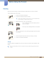
Cleaning
Exercise care when cleaning as the panel and exterior of advanced LCDs are easily scratched.
Take the following steps when cleaning.
1.
Power off the monitor and computer.
2.
Disconnect the power cord from the monitor.
Hold the power cable by the plug and do not touch the cable with wet
hands. Otherwise, an electric shock may result.
3.
Wipe the monitor with a clean, soft and dry cloth.
z
Do not use detergents that contain alcohol, solvent or
surface-active agents.
!
z
Do not spray water or detergent directly on the product.
4.
Wet a soft and dry cloth in water and wring thoroughly to clean the exterior
of the monitor.
5.
Connect the power cord to the monitor when cleaning is finished.
6.
Power on the monitor and computer.
Storage
High-glossy models can develop white stains on the surface if an ultrasonic wave humidifier is used
nearby.
Contact Customer Service Center if the inside of the monitor needs cleaning (service fee will be
charged).
Before Using the Product
3
Before Using the Product
Safety Precautions
CAUTION
RISK OF ELECTRIC SHOCK DO NOT OPEN
CAUTION : TO REDUCE THE RISK OF ELECTRIC SHOCK, DO NOT REMOVE COVER (OR
BACK). THERE ARE NO USER SERVICEABLE PARTS INSIDE. REFER ALL SERVICING TO
QUALIFIED PERSONNEL.
This symbol indicates that high voltage is present inside. It is dangerous to
make any kind of contact with any internal part of this product.
This symbol alerts you that important literature concerning operation and
maintenance has been included with this product.
Symbols
Warning
A serious or fatal injury may result if instructions are not followed.
Caution
Personal injury or damage to properties may result if instructions are
not followed.
Activities marked by this symbol are prohibited.
Instructions marked by this symbol must be followed.
Before Using the Product
4
Before Using the Product
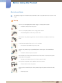
Electricity and Safety
The following images are for reference only. Real-life situations may differ from what is shown in the
images.
Warning
Do not use a damaged power cord or plug, or a loose power socket.
z
An electric shock or fire may result.
Do not use multiple products with a single power socket.
z
Overheated power sockets may cause a fire.
Do not touch the power plug with wet hands. Otherwise, an electric shock may
result.
Insert the power plug all the way in so it is not loose.
z
An unsecure connection may cause a fire.
!
Connect the power plug to a grounded power socket (type 1 insulated devices
only).
!
z
An electric shock or injury may result.
Do not bend or pull the power cord with force. Be careful not to leave the power
cord under a heavy object.
z
Damage to the cord may result in a fire or electric shock.
Do not place the power cord or product near heat sources.
z
A fire or electric shock may result.
Clean any dust around the pins of the power plug or the power socket with a dry
cloth.
!
z
A fire may result.
Before Using the Product
5
Before Using the Product
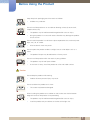
Caution
Do not disconnect the power cord while the product is being used.
z
The product may become damaged by an electric shock.
Only use the power cord provided with your product by Samsung. Do not use the
power cord with other products.
z
!
A fire or electric shock may result.
Keep the power socket where the power cord is connected unobstructed.
z
The power cord must be disconnected to cut off power to the product when
an issue occurs.
!
z
Note that the product is not completely powered down by using only the
power button on the remote.
Hold the plug when disconnecting the power cord from the power socket.
z
An electric shock or fire may result.
!
Installation
Warning
DO NOT PLACE CANDLELS, INSECT REPELLANTS OR CIGARETTES ON TOP
OF THE PRODUCT. DO NOT INSTALL THE PRODUCT NEAR HEAT SOURCES.
z
A fire may resullt.
Have a technician install the wall-mount hanger.
!
z
Installation by an unqualified person can result in an injury.
z
Only use approved cabinets.
Do not install the product in poorly ventilated spaces such as a bookcase or
closet.
z
An increased internal temperature may cause a fire.
Install the product at least 10cm away from the wall to allow ventilation.
z
An increased internal temperature may cause a fire.
!
Before Using the Product
6
Before Using the Product
Keep the plastic packaging out of the reach of children.
z
Children may suffocate.
!
Do not install the product on an unstable or vibrating surface (insecure shelf,
sloped surface, etc.)
z
The product may fall and become damaged and/or cause an injury.
z
Using the product in an area with excess vibration may damage the product
or cause a fire.
Do not install the product in a vehicle or a place exposed to dust, moisture (water
drips, etc.), oil, or smoke.
z
!
A fire or electric shock may result.
Do not expose the product to direct sunlight, heat, or a hot object such as a
stove.
z
The product lifespan may be reduced or a fire may result.
Do not install the product within the reach of young children.
z
The product may fall and injure children.
z
As the front is heavy, install the product on a flat and stable surface.
Caution
Do not drop the product while moving.
z
Product failure or personal injury may result.
!
Do not set down the product on its front.
z
The screen may become damaged.
When installing the product on a cabinet or shelf, make sure that the bottom
edge of the front of the product is not protruding.
z
The product may fall and become damaged and/or cause an injury.
z
Install the product only on cabinets or shelves of the right size.
Before Using the Product
7
Before Using the Product
Set down the product gently
z
Product failure or personal injury may result.
!
SAMSUNG
!
Installing the product in an unusual place (a place exposed to a lot of fine
particles, chemical substances or extreme temperatures, or an airport or train
station where the product should operate continuously for an extended period of
time) may seriously affect its performance.
z
Be sure to consult Samsung Customer Service Center if you want to install
the product at such a place.
Operation
Warning
There is a high voltage inside the product. Never disassemble, repair or modify
the product yourself.
z
A fire or electric shock may result.
z
Contact Samsung Customer Service Center for repairs.
Before moving the product, turn off the power switch and disconnect the power
cord, antenna cable and all other connected cables.
!
z
Damage to the cord may result in a fire or electric shock.
If the product generates abnormal sounds, a burning smell or smoke, disconnect
the power cord immediately and contact Samsung Customer Service Center.
!
z
An electric shock or fire may result.
Do not let children hang from the product or climb on top of it.
z
Children may become injured or seriously harmed.
If the product is dropped or the outer case is damaged, turn off the power switch
and disconnect the power cord. Then contact Samsung Customer Service
Center.
z
Continued use can result in a fire or electric shock.
Do not leave heavy objects or items that children like (toys, sweets, etc.) on top of
the product.
z
The product or heavy objects may fall as children try to reach for the toys or
sweets resulting in a serious injury.
Before Using the Product
8
Before Using the Product
During a lightning or thunderstorm, remove the power cord and do not touch the
antenna cable.
z
!
A fire or electric shock may result.
Do not drop objects on the product or apply impact.
z
A fire or electric shock may result.
!
Do not move the product by pulling the power cord or any cable.
z
Product failure, an electric shock or fire may result from a damaged cable.
If a gas leakage is found, do not touch the product or power plug. Also, ventilate
the area immediately.
!
GAS
z
Sparks can cause an explosion or fire.
z
Never touch the power cord or antenna cable when thunder or lightning is
present.
Do not lift or move the product by pulling the power cord or any cable.
z
Product failure, an electric shock or fire may result from a damaged cable.
Do not use or keep combustible spray or an inflammable substance near the
product.
!
z
An explosion or fire may result.
Ensure the vents are not blocked by tablecloths or curtains.
z
An increased internal temperature may cause a fire.
Before Using the Product
9
Before Using the Product
100
Do not insert metallic objects (chopsticks, coins, hairpins, etc) or objects that
burn easily (paper, matches, etc) into the product (via the vent or input/output
ports, etc).
z
Be sure to power off the product and disconnect the power cord when water
or other foreign substances have entered the product. Then contact
Samsung Customer Service Center.
z
Product failure, an electric shock or fire may result.
Do not place objects containing liquid (vases, pots, bottles, etc) or metallic
objects on top of the product.
z
Be sure to power off the product and disconnect the power cord when water
or other foreign substances have entered the product. Then contact
Samsung Customer Service Center.
z
Product failure, an electric shock or fire may result.
Caution
Leaving the screen fixed on a stationary image for an extended period of time
may cause afterimage burn-in or defective pixels.
z
!
Activate power-saving mode or a moving-picture screen saver if you will not
be using the monitor for an extended period of time.
-_!
Disconnect the power cord from the power socket if you do not plan on using the
product for an extended period of time (vacation, etc).
z
Dust accumulation combined with heat can cause a fire, electric shock or
electric leakage.
Use the product at the recommended resolution and frequency.
z
Your eyesight may deteriorate.
!
Do not hold the monitor upside-down or move it by holding the stand.
z
The product may fall and become damaged or cause an injury.
Looking at the screen too close for an extended period of time can deteriorate
your eyesight.
!
Before Using the Product
10
Before Using the Product
Do not use humidifiers or stoves around the product.
z
A fire or electric shock may result.
Rest your eyes for more than 5 minutes for every 1 hour of product use.
z
Eye fatigue will be relieved.
!
Do not touch the screen when the product has been turned on for an extended
period of time as it will become hot.
Store small accessories out of the reach of children.
!
Exercise caution when adjusting the product angle or stand height.
!
z
Your hand or finger may get stuck and injured.
z
Tilting the product at an excessive angle may cause the product to fall and
an injury may result.
Do not place heavy objects on the product.
z
Product failure or personal injury may result.
Before Using the Product
11
Table Of Contents
BEFORE USING THE
PRODUCT
PREPARATIONS
CONNECTING AND USING
A SOURCE DEVICE
2
Copyright
3
Cleaning
3
Storage
4
Safety Precautions
4
5
6
8
Symbols
Electricity and Safety
Installation
Operation
18
Checking the Contents
18
19
Removing the Packaging
Checking the Components
20
Parts
20
21
22
23
Frontal Sensor
Reverse Side
Anti-theft Lock
Remote Control
26
Before Installing the Product (Installation
Guide)
26
27
29
Tilting Angle and Rotation
Ventilation
Dimensions
30
Installing the Wall Mount
30
30
31
Preparing before installing Wall-Mount
Installing the Wall Mount Kit
Wall Mount Kit Specifications (VESA)
32
Remote Control
32
34
Cable Connection
Control Codes
45
Before Connecting
45
Pre-connection Checkpoints
Table Of Contents
12
Table Of Contents
USING MDC
46
Connecting and Using a PC
46
48
49
Connecting to a PC
Driver Installation
Changing the Resolution
52
Connecting to a Video Device
52
53
54
Connection Using the Video Cable
Connection Using the RGB-component Cable
Connection Using an HDMI-DVI Cable
55
Connecting to a TV Tuner Box (US Only)
56
Connecting and Using a Source Device
56
Source List/Edit Name
61
Configuring Settings for Multi Control
61
Configuring settings for Multi Control
61
Connection Using the RS232C Cable
62
MDC Program Installation/Uninstallation
62
62
Installation
Uninstallation
63
Using the MDC Program
63
64
65
66
67
68
70
71
73
76
77
85
87
92
Connecting to MDC
Connection Management
Auto Set ID
Cloning
Command Retry
Getting Started with MDC
Main Screen Layout
Menus
Screen Adjustment
Sound Adjustment
System Setup
Tool Settings
Other Functions
Troubleshooting Guide
Table Of Contents
13
Table Of Contents
SCREEN ADJUSTMENT
94
Mode
94
Changing the Picture Mode
96
Custom
96
Configuring the Custom Settings
99
Color Tone
99
Configuring the Color Tone Settings
100
Color Control
100
Configuring the Color Control Settings
101
Color Temp.
101
Configuring the Color Temp. Settings
102
Image Lock
102
Configuring the Image Lock Settings
103
Auto Adjustment
103
Configuring the Auto Adjustment Settings
104
Signal Balance
104
Configuring the Signal Balance Settings
106
Size
106
Changing the Picture Size
108
Digital NR
108
Enabling Digital NR
109
HDMI Black Level
109
Configuring the HDMI Black Level Settings
110
Film Mode
110
Enabling Film Mode
111
Dynamic Contrast
111
Changing the Dynamic Contrast Setting
112
Lamp Control
112
Changing the Lamp Control Setting
Table Of Contents
14
Table Of Contents
SOUND ADJUSTMENT
SETTINGS
113
Picture Reset
113
Activating Picture Reset
114
Mode
114
Changing the Mode Setting
115
Custom
115
Configuring the Custom Settings
116
Auto Volume
116
Changing the Auto Volume Setting
117
SRS TS XT
117
Setting SRS TS XT
118
Sound Reset
118
Resetting Sound Settings (Sound Reset)
119
Language
119
Changing the Language
120
Time
120
121
122
123
Clock Set
Sleep Timer
Timer1 / Timer2 / Timer3
Holiday Management
124
Menu Transparency
124
Changing Menu Transparency
125
Safety Lock
125
126
Change PIN
Lock
127
Energy Saving
127
Setting Energy Saving
Table Of Contents
15
Table Of Contents
TROUBLESHOOTING
GUIDE
128
Video Wall
128
129
130
131
132
Video Wall
Format
Horizontal
Vertical
Screen Position
133
Safety Screen
133
135
136
137
Pixel Shift
Timer
Bar / Eraser
Side Gray
137
Resolution Select
137
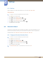
Changing the Resolution (Resolution Select)
138
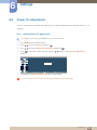
Power On Adjustment
138
Setting Power On Adjustment
139
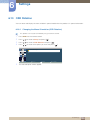
OSD Rotation
139
Changing the Menu Orientation (OSD Rotation)
140
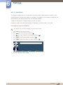
Advanced Settings
140
141
142
143
144
144
Temperature
Auto Power
User Auto Color
Standby Control
Lamp Schedule
OSD Display
146
Setup Reset
146
Resetting Setup (Setup Reset)
146
Reset All
146
Resetting All Settings (Reset All)
147
Requirements Before Contacting
Samsung Customer Service Center
147
147
148
Testing the Product
Checking the Resolution and Frequency
Check the followings.
Table Of Contents
16
Table Of Contents
SPECIFICATIONS
APPENDIX
151
Q&A
153
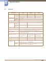
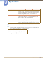
General
155
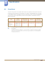
PowerSaver
156
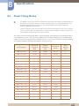
Preset Timing Modes
158
Contact SAMSUNG WORLDWIDE
163
Optimum Picture Quality and Afterimage
Burn-in Prevention
163
164
Optimum Picture Quality
Prevention of Afterimage Burn-in
167
Terminology
169
Correct Disposal
169
Correct Disposal of This Product (Waste
Electrical & Electronic Equipment)
Correct disposal of batteries in this product
169
INDEX
Table Of Contents
17
1
1.1
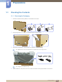
Preparations
Checking the Contents
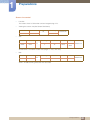
1.1.1 Removing the Packaging
1
Remove the black locking device at the bottom of the box.
1
2
2
Using the grooves in the box, lift and remove the top of the box.
3
Check the components and remove the styrofoam and plastic bag.
3
The appearance of actual components may differ from the image shown.
This image is for reference only.
4
Store the box in a dry area so that it can be used when moving the product in the future.
1 Preparations
18
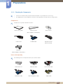
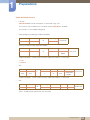
1.1.2 Checking the Components
z
Contact the vendor where you purchased the product if any components are missing.
z
The appearance of the components and items sold separately may differ from the image shown.
Components
Components may differ in different locations.
Quick setup guide
Warranty card
User manual
(Not available in all locations)
Power cord
D-SUB cable
Remote Control
(BP59-00138A)
+
-
1
Preparations
+
Batteries
(Not available in all locations)
Items sold separately
The following items can be purchased at your nearest retailer.
Wall-mount KIT
RS232C cable
RCA stereo cable
RGB-BNC cable
RGB-component cable
Video cable
1 Preparations
19
1
Preparations
TV tuner box
1.2
Parts
1.2.1 Frontal Sensor
z
The color and shape of parts may differ from what is shown. Specifications are subject to change
without notice to improve quality.
z
This product can only be controlled by using the remote control.
Sensor
Power lamp
Description
Normal: On / Energy saving: Blinks
Refer to "8.2 PowerSaver" for details on Energy Saving mode.
Remote sensor
Receives signals from the remote
Keep the area between the remote sensor and remote control
obstacle-free.
1 Preparations
20
1
Preparations
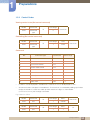
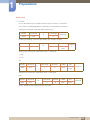
1.2.2 Reverse Side
The color and shape of parts may differ from what is shown. Specifications are subject to change
without notice to improve quality.
AV IN
DVI IN
RGB/COMPONENT IN
ON
POWER IN POWER S/W
AUDIO IN
RS232C IN
DC OUT
(5V/1.5A)
Port
Description
[POWER S/W] ON [ I ] / OFF
Power switch
[POWER IN]
Connects to the power cord
[DVI IN]
Connects to a source device using a DVI cable or HDMI-DVI cable
[AV IN]
Connects to a source device using the Video cable
[AUDIO IN]
Connects to the audio of a source device
[RGB/COMPONENT IN]
Connects to a source device using the D-SUB or RGB-component
cable
[DC OUT (5V/1.5A)]
Be sure to connect the [DC OUT] port to a TV tuner box specified by
Samsung. Otherwise, the product performance may be affected.
[RS232C IN]
Connects to an MDC using the RS232C cable
1 Preparations
21
1
Preparations
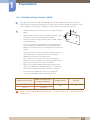
1.2.3 Anti-theft Lock
z
An anti-theft lock allows you to use the product securely even in public places.
z
The locking device shape and locking method depend on the manufacturer. Refer to the user
guide provided with your anti-theft locking device for details.
To lock an anti-theft locking device:
1
Fix the cable of your anti-theft locking device to a heavy object
such as a desk.
2
3
Put one end of the cable through the loop on the other end.
Insert the locking device into the anti-theft lock slot at the back of
the product.
4
Lock the locking device.
z
An anti-theft locking device can be purchased separately.
z
Refer to the user guide provided with your anti-theft locking
device for details.
z
Anti-theft locking devices can be purchased at electronics
retailers or online.
1 Preparations
22
1.2.4 Remote Control
z
Using other display devices in the same space as the remote control of this product can cause the
other display devices to be inadvertently controlled.
z
Remote control button functions may differ for different products.
POWER
OFF
Power on the product.
Power off the product.
.QZ
Not enabled on this product.
ABC
DEF
1
2
3
GHI
JKL
MNO
4
5
6
PRS
TUV
WXY
7
8
9
DEL -/--
SYMBOL
ENTER
-
0
PRE-CH
GUIDE
Adjust the volume.
Enter the password when prompted
while using the onscreen display menu,
or change the channel.
Return to the previous channel.
Mute the sound.
Unmuting the sound: Press MUTE again or
press the volume control (+ VOL -) button.
MUTE
VOL
SOURCE
CH/P
D.MENU
MENU
TV
Change the channel in TV mode.
Change the input source.
RN
TU
Not enabled on this product.
RE
LS
Display or hide the onscreen display
menu when the input source is TV.
TO
O
Switch the input source to TV.
Display or hide the onscreen display
menu, or return to the previous menu.
Return to the previous menu.
Move to the upper, lower, left or right
menu, or adjust an option's setting.
Confirm a menu selection.
Exit the current menu.
IN
FO
Display information about
the current input source.
EX
IT
1
Preparations
These buttons are used when you
configure settings under Channel List
in TV mode.
Not enabled on this product.
TTX/MIX
BP59-00138A
MTS/DUAL
MagicInfo
Not enabled on this product.
Configure the audio settings.
1 Preparations
23
1
Preparations
Adjusting the OSD with the Remote Control
MENU
IT
1.
Open the OSD menu.
2.
Select from Input, Picture, Sound, Setup or Multi Control in the
displayed OSD menu screen.
3.
Change settings as desired.
4.
Finish setting.
5.
Close the onscreen display (OSD) menu.
EX
To place batteries in the remote control:
1
2
3
Open the back lid of the remote control.
Place two AAA batteries (1.5V) in the right direction.
Close the lid.
Batteries are sold separately.
1 Preparations
24
Remote Control Reception Range
7m ~ 10m
1
Preparations
Use the remote control within 7m to 10m from the sensor on the product at an angle of 30˚ from the left
and right.
z
Store used batteries out of reach of children and recycle.
z
Do not use a new and used battery together. Replace both batteries at the same time.
z
Remove batteries when the remote control is not to be used for an extended period of time.
1 Preparations
25
1
1.3
Preparations
Before Installing the Product (Installation Guide)
To prevent injury, this apparatus must be securely attached to the floor/wall in accordance with the
installation instructions.
z
Ensure that an authorized installation company installs the wall mount.
z
Otherwise, it may fall and cause personal injury.
z
Make sure to install the specified wall mount.
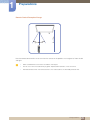
1.3.1 Tilting Angle and Rotation
Contact Samsung Customer Service Center for further details.
15 A The product can be tilted at a maximum angle of 15 from a perpendicular wall surface.
B To use the product vertically (portrait), turn it clockwise so that the LED is pointing down.
1 Preparations
26
1
Preparations
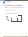
1.3.2 Ventilation
1. Installation on a Perpendicular Wall
A Minimum 40 mm
B Ambient temperature: Under 35 C
z
When installing the product on a perpendicular wall, allow
at least 40 mm of space between the product and wall
surface for ventilation and ensure that the ambient
A
temperature is kept below 35 C.
B
Figure 1.1 Side view
1 Preparations
27
1
Preparations
2. Installation on an Indented Wall
Contact Samsung Customer Service Center for further details.
B
D
D
Plane view
A
A Minimum 40 mm
B Minimum 70 mm
C Minimum 50 mm
D Minimum 50 mm
C
E
E Ambient temperature: Under 35 C
Figure 1.2 Side view
When installing the product on an indented wall, allow at least the space specified above between the
product and wall for ventilation and ensure that the ambient temperature is kept below 35 C.
3. Installation in an Indented Floor
Contact Samsung Customer Service Center for further details.
A Minimum 50 mm
B Ambient temperature: Under
20 C
A
B
Figure 1.3 Side view
When installing the product in an indented floor, allow at least 50 mm of space between the product
and floor surface for ventilation and ensure that the ambient temperature is kept below 20 C.
1 Preparations
28
1
Preparations
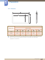
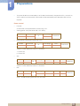
1.3.3 Dimensions
5
1
2
4
3
SET - Dimension (W x D x H) [mm]
Without STAND
Model name
1
2
3
4
5
320BX
782.0
697.7
392.3
478.5
85.5
400BX
969.0
888.8
501.4
582.0
91.0
460BX
1102.0
1019.8
574.6
656.8
91.4
All drawings are not necessarily to scale. Some dimensions are subject to change without prior notice.
Refer to the dimensions prior to performing installation of your product. Not responsible for
typographical or printed errors.
1 Preparations
29
1
1.4
Preparations
Installing the Wall Mount
1.4.1 Preparing before installing Wall-Mount
To install a wall-mount from another manufacturer, use the
Holder-Ring.
1
1.4.2 Installing the Wall Mount Kit
The wall mount kit (sold separately) allows you to mount the product on the wall.
For detailed information on installing the wall mount, see the instructions provided with the wall mount.
We recommend you contact a technician for assistance when installing the wall mount bracket.
Samsung Electronics is not responsible for any damage to the product or injury to yourself or others if
you elect to install the wall mount on your own.
1 Preparations
30
1
Preparations
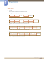
1.4.3 Wall Mount Kit Specifications (VESA)
Install your wall mount on a solid wall perpendicular to the floor. Before attaching the wall mount to
surfaces other than plaster board, please contact your nearest dealer for additional information. If you
install the product on a ceiling or slanted wall, it may fall and result in severe personal injury.
z
Standard dimensions for wall mount kits are shown in the table
below.
z
Samsung wall mount kits contain a detailed installation manual
and all parts necessary for assembly are provided.
z
Do not use screws that do not comply with the VESA standard
screw specifications.
z
Do not use screws that are longer than the standard length or
do not comply with the VESA standard screw specifications.
Screws that are too long may cause damage to the inside of the
product.
z
For wall mounts that do not comply with the VESA standard
screw specifications, the length of the screws may differ
depending on the wall mount specifications.
z
Do not fasten the screws too firmly. This may damage the
product or cause the product to fall, leading to personal injury.
Samsung is not liable for these kinds of accidents.
z
Samsung is not liable for product damage or personal injury
when a non-VESA or non-specified wall mount is used or the
consumer fails to follow the product installation instructions.
z
Do not mount the product at more than a 15 degree tilt.
z
Always have two people mount the product on a wall.
Product size in inches
VESA screw hole specs
(A * B) in millimeters
32~40
200 X 200
46~55
400 X 400
Standard Screw
Quantity
M8
4
Do not install your Wall Mount Kit while your product is turned on. It may result in personal injury due to
electric shock.
1 Preparations
31
1
1.5
Preparations
Remote Control
1.5.1 Cable Connection
z
Interface
RS232C (9 pins)
Pin
TxD (No. 2), RxD (No. 3), GND (No. 5)
Bit rate
9600 bps
Data bits
8 bit
Parity
None
Stop bit
1 bit
Flow control
None
Maximum length
15m (only shielded type)
Pin assignment
1 2 3 4 5
6 7 8 9
Pin
Signal
1
Detect data carrier
2
Received data
3
Transmitted data
4
Prepare data terminal
5
Signal ground
6
Prepare data set
7
Send request
8
Clear to send
9
Ring indicator
1 Preparations
32
1
Preparations
z
RS232C cable
Connector: 9-pin D-Sub
Cable: Cross (reversed) cable
9
5
5
9
6
1
1
6
-P1Female
-P2-
-P2-
Rx
2
-------->
3
Rx
Tx
3
<--------
2
Tx
Gnd
5
---------
5
Gnd
Female
Connection
RS232C IN
z
-P1-
1 Preparations
33
1
Preparations
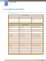
1.5.2 Control Codes
Viewing control state (Get control command)
Header
Command
0xAA
Command
type
Data length
ID
0
Checksum
Data length
Data
1
Value
Controlling (Set control command)
Header
Command
0xAA
Command
type
ID
Checksum
Command
No.
Command type
Command
Value range
1
Power control
0x11
0~1
2
Volume control
0x12
0~100
3
Input source control
0x14
-
4
Screen mode control
0x18
-
5
Screen size control
0x19
0~255
6
PIP on/off control
0x3C
0~1
7
Auto adjustment control
0x3D
0
8
Video wall mode control
0x5C
0~1
9
Safety Lock
0x5D
0~1
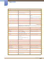
z
Issued IDs can be displayed in hexadecimals. However, ID 0 must be displayed as 0xFF.
z
All communications take place in hexadecimals. The checksum is calculated by adding up all values
except the header. If a checksum adds up to be more than 2 digits as shown below
(11+FF+01+01=112), the first digit is removed.
E.g. Power On & ID=0
Header
Command
Data length
Data 1
1
"Power"
Data length
Data 1
1
1
ID
0xAA
0x11
Header
Command
Checksum
ID
0xAA
0x11
12
1 Preparations
34
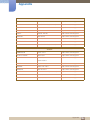
1
Preparations
z
To control all devices connected by a serial cable simultaneously irrespective of IDs, set the ID as
"0xFE" and transmit commands. Commands will be executed by each device but ACK will not
respond.
Power control
z
Function
A TV/monitor can be powered on and off using a PC.
z
Viewing power state (Get Power ON / OFF Status)
Header
Command
Data length
ID
0xAA
z
Checksum
0x11
0
Setting power ON/Off (Set Power ON / OFF)
Header
Command
Data length
Data
1
"Power"
ID
0xAA
Checksum
0x11
"Power": Power code to be set on a TV/monitor
1 : Power ON
0 : Power OFF
z
Ack
Header
Command
Data length
Ack/Nak
r-CMD
Val1
3
‘A’
0x11
"Power"
Data length
Ack/Nak
r-CMD
Val1
3
‘N’
0x11
"ERR"
ID
0xAA
0xFF
Checksum
"Power": Power code to be set on a TV/monitor
z
Nak
Header
Command
ID
0xAA
0xFF
Checksum
"ERR" : A code showing what error has occurred
1 Preparations
35
1
Preparations
Volume control
z
Function
The volume of a TV/monitor can be adjusted using a PC.
z
Viewing volume state (Get Volume Status)
Header
Command
Data length
ID
0xAA
z
Checksum
0x12
0
Setting the volume (Set Volume)
Header
Command
Data length
Data
1
"Volume"
ID
0xAA
Checksum
0x12
"Volume": Volume value code to be set on a TV/monitor (0-100)
z
Ack
Header
Command
Data length
Ack/Nak
r-CMD
Val1
3
‘A’
0x12
"Volume"
ID
0xAA
0xFF
Checksum
"Volume": Volume value code to be set on a TV/monitor (0-100)
z
Nak
Header
Command
Data length
Ack/Nak
r-CMD
Val1
3
‘N’
0x12
"ERR"
ID
0xAA
0xFF
Checksum
"ERR" : A code showing what error has occurred
1 Preparations
36
1
Preparations
Input source control
z
Function
The input source of a TV/monitor can be changed using a PC.
z
Viewing input source state (Get Input Source Status)
Header
Command
Data length
ID
0xAA
z
0x14
Checksum
0
Setting the input source (Set Input Source)
Header
Command
0xAA
0x14
ID
Data length
Data
1
"Input
Source"
Checksum
"Input Source": An input source code to be set on a TV/monitor
0x14
PC
0x1E
BNC
0x18
DVI
0x0C
Input source
0x04
S-video
0x08
Component
0x20
MagicInfo
0x1F
DVI_video
0x30
RF (TV)
0x40
DTV
0x21
HDMI1
0x22
HDMI1_PC
0x23
HDMI2
0x24
HDMI2_PC
0x25
DisplayPort
DVI_video, HDMI1_PC and HDMI2_PC cannot be used with the Set command. They only
respond to "Get" commands.
This model does not support BNC, S-Video, HDMI1, HDMI1_PC, HDMI2, HDMI2_PC, and
Display ports.
MagicInfo is only available with models that contain the MagicInfo function.
RF (TV) and DTV are only available with models that include a TV.
1 Preparations
37
1
Preparations
z
Ack
Header
Command
0xAA
0xFF
Data length
Ack/Nak
r-CMD
Val1
3
‘A’
0x14
"Input
Source"
ID
Checksum
"Input Source": An input source code to be set on a TV/monitor
z
Nak
Header
Command
Data length
Ack/Nak
r-CMD
Val1
3
‘N’
0x14
"ERR"
ID
0xAA
0xFF
Checksum
"ERR" : A code showing what error has occurred
1 Preparations
38
1
Preparations
Screen
z
Function
The screen mode of a TV/monitor can be changed using a PC.
Screen mode cannot be controlled when the Video Wall function is enabled.
This control can only be used on models that include a TV.
z
Viewing screen status (Get Screen Mode Status)
Header
Command
Data length
ID
0xAA
z
Checksum
0x18
0
Setting the picture size (Set Picture Size)
Header
Command
0xAA
0x18
Data length
Data
1
"Screen
Mode"
ID
Checksum
"Screen Mode": A code that sets the TV/monitor status
z
0x01
16 : 9
0x04
Zoom
0x31
Wide Zoom
0x0B
4:3
Ack
Header
Command
0xAA
0xFF
Data length
Ack/Nak
r-CMD
Val1
3
‘A’
0x18
"Screen
Mode"
ID
Checksum
"Screen Mode": A code that sets the TV/monitor status
z
Nak
Header
Command
Data length
Ack/Nak
r-CMD
Val1
3
‘N’
0x18
"ERR"
ID
0xAA
0xFF
Checksum
"ERR" : A code showing what error has occurred
1 Preparations
39
1
Preparations
Screen size control
z
Function
The screen size of a TV/monitor can be changed using a PC.
z
Viewing the screen size (Get Screen Size Status)
Header
Command
Data length
ID
0xAA
z
Checksum
0x19
0
Ack
Header
Command
0xAA
0xFF
Data length
Ack/Nak
r-CMD
Val1
3
‘A’
0x19
"Screen
Size"
ID
Checksum
"Screen Size": TV/monitor screen size (range: 0 – 255, unit: inch)
z
Nak
Header
Command
Data length
Ack/Nak
r-CMD
Val1
3
‘N’
0x19
"ERR"
ID
0xAA
0xFF
Checksum
"ERR" : A code showing what error has occurred
1 Preparations
40
1
Preparations
PIP On/Off control
z
Function
The PIP mode of a TV/monitor can be turned on or off using a PC.
z
Only available on models that have the PIP function.
The mode cannot be controlled if Video Wall is set to On.
This function is not available in MagicInfo.
Viewing PIP on/off state (Get the PIP ON / OFF Status)
Header
Command
Data length
ID
0xAA
z
Checksum
0x3C
0
Setting PIP on/off (Set the PIP ON / OFF)
Header
Command
Data length
Data
1
"PIP"
ID
0xAA
Checksum
0x3C
"PIP": A code used to turn the PIP mode of a TV/monitor on or off
1 : PIP ON
0 : PIP OFF
z
Ack
Header
Command
Data length
Ack/Nak
r-CMD
Val1
3
‘A’
0x3C
"PIP"
ID
0xAA
0xFF
Checksum
"PIP": A code used to turn the PIP mode of a TV/monitor on or off
z
Nak
Header
Command
Data length
Ack/Nak
r-CMD
Val1
3
‘N’
0x3C
"ERR"
ID
0xAA
0xFF
Checksum
"ERR" : A code showing what error has occurred
1 Preparations
41
1
Preparations
Auto adjustment control (PC and BNC only)
z
Function
Automatically adjust the PC system screen using a PC.
z
Viewing auto adjustment state (Get Auto Adjustment Status)
z
Setting auto adjustment (Set Auto Adjustment)
Header
Command
0xAA
0x3D
Data length
Data
1
"Auto
Adjustment"
ID
Checksum
"Auto Adjustment" : 0x00 (at all times)
z
Ack
Header
Command
0xAA
0xFF
Data length
Ack/Nak
r-CMD
Val1
3
‘A’
0x3D
"Auto
Adjustment"
ID
z
Checksum
Nak
Header
Command
Data length
Ack/Nak
r-CMD
Val1
3
‘N’
0x3D
"ERR"
ID
0xAA
0xFF
Checksum
"ERR" : A code showing what error has occurred
1 Preparations
42
1
Preparations
Video Wall Mode Control
z
Function
Video Wall Mode can be activated on a TV/monitor using a PC.
This control is only available on a TV/monitor whose Video Wall is enabled.
This function is not available in MagicInfo.
z
Viewing video wall mode (Get Video Wall Mode)
Header
Command
Data length
ID
0xAA
z
Checksum
0x5C
0
Setting the video wall (Set Video Wall Mode)
Header
Command
0xAA
0x5C
Data length
Data
1
"Video Wall
Mode"
ID
Checksum
"Video Wall Mode": A code used to activate Video Wall mode on a TV/monitor
1 : Full
0 : Natural
z
Ack
Header
Command
0xAA
0xFF
Data length
Ack/Nak
r-CMD
Val1
3
‘A’
0x5C
"Video Wall
Mode"
ID
Checksum
"Video Wall Mode": A code used to activate Video Wall mode on a TV/monitor
z
Nak
Header
Command
Data length
Ack/Nak
r-CMD
Val1
3
‘N’
0x5C
"ERR"
ID
0xAA
0xFF
Checksum
"ERR" : A code showing what error has occurred
1 Preparations
43
1
Preparations
Safety Lock
z
Function
PC can be used to turn the Safety Lock function on or off on a TV/monitor.
This control is available regardless of whether or not the power is turned on.
z
Viewing the safety lock state (Get Safety Lock Status)
Header
Command
Data length
ID
0xAA
z
Checksum
0x5D
0
Enabling or disabling safety lock (Set Safety Lock Enable / Disable)
Header
Command
0xAA
0x5D
Data length
Data
1
"Safety
Lock"
ID
Checksu
m
"Safety Lock": Safety lock code to be set on a TV/monitor
1 : ON
0 : OFF
z
Ack
Header
Command
0xAA
0xFF
Data length
Ack/Nak
r-CMD
Val1
3
‘A’
0x5D
"Safety
Lock"
ID
Checksum
"Safety Lock": Safety lock code to be set on a TV/monitor
z
Nak
Header
Command
Data length
Ack/Nak
r-CMD
Val1
3
‘N’
0x5D
"ERR"
ID
0xAA
0xFF
Checksum
"ERR" : A code showing what error has occurred
1 Preparations
44
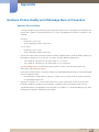
2
2.1
Connecting and Using a Source Device
Before Connecting
Check the following before you connect this product with other devices.
Devices that can be connected to this product include PCs, camcorders, speakers, set top boxes and
DVD/Blu-ray Disc players.
2.1.1 Pre-connection Checkpoints
z
Before connecting a source device, read the user manual provided with it. The number and locations
of ports on source devices may differ from device to device.
z
Do not connect the power cable until all connections are completed. Connecting the power cable
during connection may damage the product.
z
Connect the sound ports correctly: left = white and right = red.
Audio input received via an audio-in port will be outputted via the PC, DVI, AV or Component port.
z
Check the types of ports at the back of the product you want to connect.
2 Connecting and Using a Source Device
45
2
2.2
Connecting and Using a Source Device
Connecting and Using a PC
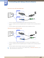
2.2.1 Connecting to a PC
z
A PC can be connected to the product in a variety of ways.
Select a connection method suitable for your PC.
Connecting parts may differ in different products.
Connection using the D-SUB cable (analogue type)
RGB /
COMPONENT IN
AUDIO IN
1
Connect the D-SUB cable to the [RGB/COMPONENT IN] port on the product and the D-SUB port
on the PC.
2
Connect a sound output cable to the [AUDIO IN] port on the product and the sound output port on
the PC.
3
Connect the power cord to the product and power socket, and power on the PC.
2 Connecting and Using a Source Device
46
2
Connecting and Using a Source Device
Connection using a DVI cable (digital type)
DVI IN
AUDIO IN
1
2
Connect a DVI cable to the [DVI IN] port on the monitor and the DVI port on the PC.
Connect a sound output cable to the [AUDIO IN] port on the product and the sound output port on
the PC.
3
Connect the power cord to the product and power socket, and power on the PC.
Connection Using an HDMI-DVI Cable
DVI IN
AUDIO IN
1
2
Connect an HDMI-DVI cable to the [DVI IN] port on the monitor and the HDMI port on the PC.
Connect a sound output cable to the [AUDIO IN] port on the product and the sound output port on
the PC.
3
Connect the power cord to the product and power socket, and power on the PC.
When you connect a PC to the product using an HDMI-DVI cable, set Edit Name to DVI PC to access
video and audio content stored on the PC.
2 Connecting and Using a Source Device
47
2
Connecting and Using a Source Device
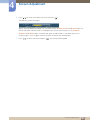
2.2.2 Driver Installation
z
You can set the optimum resolution and frequency for this product by installing the corresponding
drivers for this product.
z
An installation driver is contained on the CD supplied with the product.
If the provided files are faulty, go to the Samsung homepage (http://www.samsung.com) and
download the files.
1
2
3
4
Insert the user manual CD provided with the product into the CD-ROM drive.
5
Go to Display Properties and check that the resolution and refresh rate are appropriate.
Click "Windows Driver."
Follow the instructions given on the screen to proceed with installation.
Select your product model from the list of models.
Refer to your Windows OS manual for further details.
2 Connecting and Using a Source Device
48
2
Connecting and Using a Source Device
2.2.3 Changing the Resolution
Adjust the resolution and refresh rate in Control Panel on your PC to obtain optimum picture quality.
The picture quality of TFT-LCDs may degrade if the optimum resolution is not selected.
Changing the Resolution on Windows XP
Go to Control Panel
Display
Settings, and change the resolution.
2 Connecting and Using a Source Device
49
2
Connecting and Using a Source Device
Changing the Resolution on Windows Vista
Go to Control Panel
Personal Settings
Display Settings, and change the resolution.
2 Connecting and Using a Source Device
50
2
Connecting and Using a Source Device
Changing the Resolution on Windows 7
Go to Control Panel
Display
Screen Resolution, and change the resolution.
2 Connecting and Using a Source Device
51
2
2.3
Connecting and Using a Source Device
Connecting to a Video Device
z
You can connect a video device to the product using a cable.
Connecting parts may differ in different products.
2.3.1 Connection Using the Video Cable
AV IN
AUDIO IN
1
2
Connect the Video cable to the [AV IN] port on the product and the video port on the video device.
Connect the RCA stereo cable to the [AUDIO IN] port on the product and the matching-colored
AUDIO OUT ports on the video device.
3
Press the SOURCE button on the remote control to change the source to AV.
2 Connecting and Using a Source Device
52
2
Connecting and Using a Source Device
2.3.2 Connection Using the RGB-component Cable
AUDIO IN
RGB /
COMPONENT IN
1
Connect the RGB-component cable to the [RGB/COMPONENT IN] port on the product and the
matching-colored component ports on the video device.
2
Connect the RCA stereo cable to the [AUDIO IN] port on the product and the matching-colored
AUDIO OUT ports on the video device.
3
Press the SOURCE button on the remote control to change the source to Component.
2 Connecting and Using a Source Device
53
2
Connecting and Using a Source Device
2.3.3 Connection Using an HDMI-DVI Cable
DVI IN
AUDIO IN
1
Connect an HDMI-DVI cable to the [DVI IN] port on the product and the HDMI port on the video
device.
2
Connect the RCA stereo cable to the [AUDIO IN] port on the product and the matching-colored
AUDIO OUT ports on the video device.
3
Press the SOURCE button on the remote control to change the source to DVI.
z
Audio will not be enabled if the product is connected to a video device using an HDMI-DVI cable.
To resolve this, additionally connect an audio cable to the audio ports on the product and video
device. When you connect a video device to the product using an HDMI-DVI cable, set Edit Name
to DVI Devices to access video and audio content stored on the video device.
z
Supported resolutions include 1080p (50/60Hz), 720p (50/60Hz), 480p, and 576p.
2 Connecting and Using a Source Device
54
2
2.4
Connecting and Using a Source Device
Connecting to a TV Tuner Box (US Only)
TV tuner boxes are sold separately. Contact Samsung Customer Service Center for enquiries on the
purchase and installation of a TV tuner box.
DC OUT (5V/2.5A)
DVI IN
1
Refer to the quick installation guide provided with your TV tuner box when you connect the tuner box
to the product.
2
Connect a DP-DVI cable (which is TV-dedicated) to [DVI IN] on the product and TV OUT on the TV
tuner box.
3
Connect the power cord of the TV tuner box to the [DC OUT (5V/2.5A)] port on the product and the
power port on the TV tuner box.
4
5
6
7
Connect the antenna to the antenna port on the TV tuner box.
Connect the power cord to the product and a power socket.
Turn on the power button.
Press the SOURCE button on the remote control to change the source to TV.
2 Connecting and Using a Source Device
55
2
2.5
Connecting and Using a Source Device
Connecting and Using a Source Device
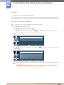
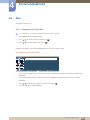
2.5.1 Source List/Edit Name
Source List allows you to select a variety of sources and change source device names.
Source List
You can display the screen of a source device connected to the product. Select a source from Source
List to display the screen of the selected source.
To change the setting in Source List:
This product can only be controlled by using the remote control.
1
2
3
Press MENU on the remote control.
Press
/
to move to Input and press [
].
Press
/
to move to Source List and press [
]. The following screen will appear.
S o u r c e L i s t
P C
D V I
A V
C o m p o n e n t
M o v e
4
Press
/
E n t e r
R e t u r n
to move to the source you want and press [
]. The screen of the selected source will
be displayed.
To use TV, connect a TV tuner box to the product. DVI will be disabled under Source List if a TV tuner
box is connected. Refer to page 55 for details about connecting to a TV.
The screen may not display correctly if an incorrect source is selected for the source device you want to
convert to.
2 Connecting and Using a Source Device
56
2
Connecting and Using a Source Device
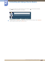
Edit Name
z
You can rename a connected source device.
Sometimes the screen will not display properly unless the name of a source device is specified in Edit
Name. In addition, it is best to rename the source device in Edit Name to obtain optimal picture quality.
To rename a source device in Edit Name:
This product can only be controlled by using the remote control.
1
2
3
Press MENU on the remote control.
Press
/
to move to Input and press [
].
Press
/
to move to Edit Name and press [
]. A list of sources (PC, DVI , etc.) will appear.
DVI will be displayed as TV if a TV tuner box is connected.
E d i t N a m e
P C
:
----
D V I
:
----
A V
:
----
C o m p o n e n t
:
----
M o v e
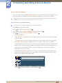
4
Press
/
E n t e r
R e t u r n
to move to the source you want and press [
]. A list of source devices will appear as
shown below.
P C
---V C R
D V D
C a b l e S T B
H D S T B
S a t e l l i t e S T B
A V R e c e i v e r
M o v e
E n t e r
R e t u r n
The list can include the following source devices. Source devices on the list differ depending on the
selected source.
VCR / DVD / Cable STB / HD STB / Satellite STB / AV Receiver / DVD Receiver / Game /
Camcorder / DVD Combo / DHR / PC / DVI PC / DVI Devices
2 Connecting and Using a Source Device
57
2
Connecting and Using a Source Device
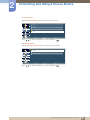
5
Press
/
to move to the source device you want and press [
]. The name of the selected
source device will be displayed as shown below.
E d i t N a m e
P C
:
A V R e c e i v e r
D V I
:
----
A V
:
----
C o m p o n e n t
:
----
M o v e
E n t e r
R e t u r n
Available settings in the Picture menu depend on the current source and settings made in Edit Name.
(Refer to page 94 for details about the Picture menu.)
2 Connecting and Using a Source Device
58
2
Connecting and Using a Source Device
Source AutoSwitch Settings
z
Turning on the display with Source AutoSwitch On, and the previous video source selection is not
active, the display will automatically search the different video input sources for active video.
If the display TV source is active (TV tuner connected to the display) the Source AutoSwitch search
function becomes inactive. The display will remain in the TV source.
Configuring Source AutoSwitch Settings
This product can only be controlled by using the remote control.
1
2
3
4
Press MENU on the remote control.
Press
/
to move to Input and press [
Press
/
to move to Source AutoSwitch Settings and press [
Press
/
to move to Source AutoSwitch and press [
z
].
].
].
Source AutoSwitch
When the Source AutoSwitch is On, the display video source will automatically be searched
for active video.
The Primary Source selection will be activated, if the current video source is not recognized.
Secondary source selection will become active, if no primary video source is available.
If both the primary and secondary input sources are not recognized, the display will perform two
searches for an active source, each search checking the primary and then secondary source. If
both searches fail, the display will return to the first video source and display a message
indicating that there is no signal.
When the Primary Source selection is set to All, the display will search all the video source
inputs twice in sequence looking for an active video source, returning back to the first video
source in the sequence if no video is found.
S o u r c e A u t o S w i t c h S e t t i n g s
S o u r c e A u t o S w i t c h
:
O f f
P r i m a r y S o u r c e
:
A l l
S e c o n d a r y S o u r c e
:
P C
M o v e
Press
/
E n t e r
R e t u r n
to select the option you want and press [
].
2 Connecting and Using a Source Device
59
2
Connecting and Using a Source Device
z
Primary Source
Specify Primary Source for the automatic input source.
Pr i m a r y S o u r c e
P C
D V I
A V
C o m p o n e n t
A l l
M o v e
Press
z
/
E n t e r
R e t u r n
to select the option you want and press [
].
Secondary Source
Specify Secondary Source for the automatic input source.
S e c o n d a r y S o u r c e
D V I
A V
C o m p o n e n t
M o v e
Press
/
E n t e r
R e t u r n
to select the option you want and press [
].
2 Connecting and Using a Source Device
60
3
Using MDC
MDC (Multiple Display Control) is an application that allows you to easily control multiple display
devices simultaneously using a PC.
3.1
Configuring Settings for Multi Control
Assign an individual ID to your product.
3.1.1 Configuring settings for Multi Control
This product can only be controlled by using the remote control.
1
2
Press MENU on the remote control.
Press
z
/
to move to Multi Control and press [
].
ID Setup
Assign an ID to a set. (Range: 00~99)
Press
z
or
to select a number, and press [
].
ID Input
Enter the ID number of the product connected to the input cable for input signal reception.
Enter the number you want using the number buttons on the remote control.
3.2
Connection Using the RS232C Cable
RS232C IN
1
Connect the RS232C cable to [RS232C IN] on the product and RS232C OUT on the PC.
3 Using MDC
61
3
3.3
Using MDC
MDC Program Installation/Uninstallation
3.3.1 Installation
1
2
Insert the installation CD into the CD-ROM drive.
Click the MDC Unified installation program.
If a software installation window is not displayed on the main screen, install with the "MDC Unified"
execution file in the MDC folder on the CD.
3
4
Click "Next" in the displayed Installation Wizard screen.
In the "License Agreement" window displayed, select "I accept the terms in the license agreement"
and click "Next".
5
6
In the displayed "Customer Information" window, fill out all the information fields and click "Next".
In the displayed "Destination Folder" window, select the directory path you want to install the
program in and click "Next".
If the directory path is not specified, the program will be installed in the default directory path.
7
In the displayed "Ready to Install the Program" window, check the directory path to install the
program in and click "Install".
8
9
Installation progress will be displayed.
Click "Finish" in the displayed "InstallShield Wizard Complete" window.
Select "Launch MDC Unified" and click "Finish" to run the MDC program immediately.
10
The MDC Unified shortcut icon will be created on the desktop after installation.
z
The MDC execution icon may not be displayed depending on the PC system or product
specifications.
z
Press F5 if the execution icon is not displayed.
3.3.2 Uninstallation
1
2
Select Settings > Control Panel on the Start menu and double-click Add/Delete Program.
Select MDC Unified from the list and click Change/Remove.
MDC installation can be affected by the graphics card, mother board and network conditions.
3 Using MDC
62
3
3.4
Using MDC
Using the MDC Program
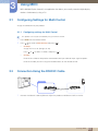
3.4.1 Connecting to MDC
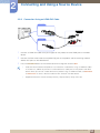
Using MDC via RS-232C (serial data communications standards)
An RS-232C serial cable must be connected to the serial ports on the PC and monitor.
Using MDC via Ethernet
Enter the IP for the primary display device and connect the device to the PC. One display device can
connect to another using an RS-232C serial cable.
3 Using MDC
63
3
Using MDC
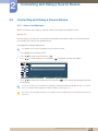
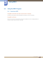
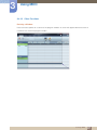
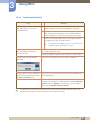
3.4.2 Connection Management
Connection management includes the Connection list and Connection list modification options.
Connection list - Connection list shows the details of the connections such as connection setting (IP/
COM, Port No, MAC, and Connection Type), connection status, Set ID Range, and detected devices.
Each connection can contain a maximum of 100 devices connected in serial daisy-chain fashion. All the
LFDs detected in a connection are displayed in the Device list, where the user can make groups and
send commands to detected devices.
Connection list modification options - Connection modification options includes Add, Edit, Delete,
and Refresh.
3 Using MDC
64
3
Using MDC
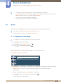
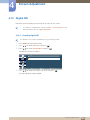
3.4.3
Auto Set ID
Auto Set ID feature assigns a Set ID for all the LFDs connected in daisy-chain of a selected connection.
There can be a maximum of 100 LFDs in a connection. The Set ID is assigned sequentially in the daisychain running from 1 to 99, and then finally to Set ID 0.
3 Using MDC
65
3
Using MDC
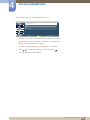
3.4.4
Cloning
Using the Cloning feature, you can copy the setting of one LFD and apply it to multiple selected LFDs.
You can select specific tab categories or all tab categories for cloning, using the copy setting option
window.
3 Using MDC
66
3
Using MDC
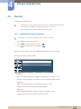
3.4.5
Command Retry
This feature is used to specify the maximum number of times the MDC command will be retried in case of
there being no reply or a corrupted reply from an LFD. The retry count value can be set using the MDC
options window. The retry count value must be between 1-10. The default value is 1.
3 Using MDC
67
3
Using MDC
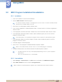
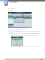
3.4.6 Getting Started with MDC
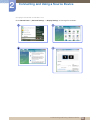
1
To start the program, click Start
2
Click Add to add a display device.
z
Programs
Samsung
MDC Unified.
If the connection is established via RS232C, go to Serial and specify the COM Port.
3 Using MDC
68
3
Using MDC
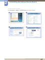
z
If the connection is established via Ethernet, enter the IP that was entered for the display
device.
3 Using MDC
69
3
Using MDC
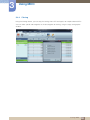
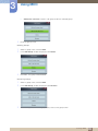
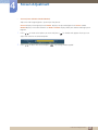
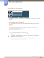
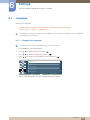
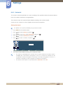
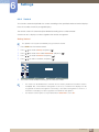
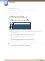
3.4.7 Main Screen Layout
1
6
5
4
2
3
1
Menu Bar
Change the status of a display device or the properties of the program.
2
Device Category
View a list of connected display devices or device groups.
3
Schedule Category
View a list of schedules for display devices.
4
Set List
Select the display device you want to adjust.
5
Modify the Set List
Add, edit, regroup or delete sets.
6
Help Topics
Display help topics for the program.
3 Using MDC
70
3
Using MDC
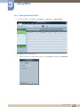
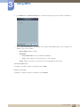
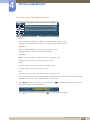
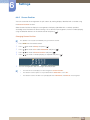
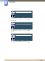
3.4.8 Menus
You can power on or off a selected device or change the input source or volume of the device.
Choose display devices from the list of sets, and select the Home tab.
1
Home
Select an item and change the corresponding setting.
Power
z
On: Power on a selected display.
z
Off: Power off a selected display.
Input
Input Source : Change the input source.
z
Input sources available can vary depending on the Display Device Models.
The input source can be changed only for displays that are turned on.
Channel : Change the channel.
z
2
The TV channel can be changed by using the up/down arrow keys.
The channel can be changed only when the input source is TV.
Only registered channels can be selected.
Volume
The volume can be changed or the sound can be muted only for displays that are turned on.
Volume
The volume can be adjusted using the slider bar in the range of 0 to 100.
Adjust the volume of a selected display.
Input
Enable or disable Mute for a selected display.
Mute will automatically be disabled if Volume is adjusted when Mute is on.
3 Using MDC
71
3
Using MDC
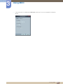
3
z
Alert
Fault Device
This menu shows a list of display devices which have following errors - fan error, temperature
error, brightness sensor error, or lamp error.
Select a display device from the list. The Repair button will be enabled. Click the refresh button
to refresh the error status of the display device. The recovered display device will disappear
from the Fault Device List.
z
Fault Device Alert
Display device in which error is detected will be reported by email.
Fill in all required fields. The Test and OK buttons will be enabled. Ensure the Sender
information and at least one Recipient are entered.
3 Using MDC
72
3
Using MDC
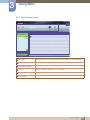
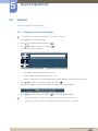
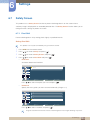
3.4.9 Screen Adjustment
The screen settings (contrast, brightness, etc.) can be adjusted.
Choose display devices from the list of sets, and select the Picture tab.
Custom
Select an item and change the corresponding screen setting.
z
Color and Tint are not available if the input source is PC.
z
Red, Green, Blue and PC Screen Adjustment are not available if the input source is Video.
z
Color, Tint, Color Tone, Color Temp, Red, Green, Blue and PC Screen Adjustment are not
available if both PC Source and Video Source are selected.
Contrast
z
Adjust the contrast for the selected display device.
Brightness
z
Adjust the brightness for the selected display device.
Color
z
Adjust the colors for the selected display device.
Tint (G/R)
z
Adjust the tint for the selected display device.
Color Tone
z
Adjust the background color tone for the selected display device.
Color Temp
z
Adjust the color temperature for the selected display device.
This option is enabled if Color Tone is set to Off.
Red
z
Customize the intensity of red color for the selected display device.
Green
z
Customize the intensity of green color for the selected display device.
3 Using MDC
73
3
Using MDC
Blue
z
Customize the intensity of blue color for the selected display device.
Options
Dynamic Contrast
Adjust the Dynamic Contrast for the selected display device.
Gamma Control
Change the gamma value for the selected display.
Auto Motion Plus
This option is used to view dynamic images.
z
Off: Disable the Auto Motion Plus function.
z
Clear: Set the level of Auto Motion Plus to clear. This mode is suitable to display vivid images.
z
Standard: Set the level of Auto Motion Plus to standard.
z
Smooth: Set the level of Auto Motion Plus to smooth. This mode is suitable to display smooth
images.
z
Custom: Customize the level of screen burn-in or flickering.
z
Demo: This function demonstrates the technology of Auto Motion Plus. The result when the mode
is changed can be previewed on the left side of the window.
Brightness Sensor
Enable or disable the Brightness Sensor for the selected display device.
The Brightness Sensor detects the ambient light intensity and automatically adjusts the screen
brightness.
Brightness Sensor may not be available depending on the product.
3 Using MDC
74
3
Using MDC
Size
Picture Size
Adjust the screen size for the selected display device.
The Detail item will be disabled if Picture Size is set to a mode that does not support detailed
configuration.
The -/+ buttons can be used to adjust Zoom.
The screen can be relocated using the up/down/left/right buttons.
Detail
You can view details of the selected screen size.
PC Screen Adjustment
Frequency adjustment or fine-tuning is available by using the -/+ buttons in Coarse or Fine.
To relocate the screen, click one of the four images below Position.
To automatically adjust the frequency, fine-tune or relocate the screen, click Auto Adjustment.
3 Using MDC
75
3
Using MDC
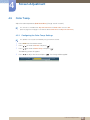
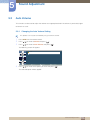
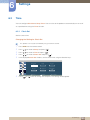
3.4.10 Sound Adjustment
You can change the sound settings.
Choose display devices from the list of sets, and select the Sound tab.
The Bass or Treble item will be disabled if the item is not supported by the selected set.
Bass
Adjust the bass for the selected display.
Treble
Adjust the treble for the selected display.
Balance (L/R)
Adjust the volume of the left and right speakers of the selected display device.
SRS TS XT
Enable or disable the SRS TS XT effect for the selected display device.
3 Using MDC
76
3
Using MDC
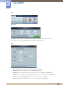
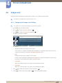
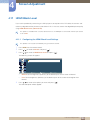
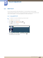
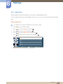
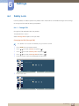
3.4.11 System Setup
Choose display devices from the list of sets, and select the System tab.
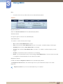
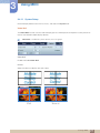
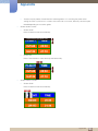
Video Wall
The Video Wall function can be used to display part of a whole picture or repeat the same picture on
each of connected multiple display devices.
Video Wall is enabled only when devices are in the group.
Video Wall
Enable or disable Video Wall.
Format
Select the format to display the split screen.
Full
Natural
3 Using MDC
77
3
Using MDC
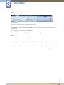
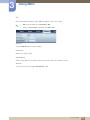
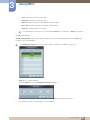
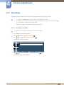
H
Select the number of horizontal display devices.
A maximum of 15 displays can be arranged in a row.
A maximum of 6 can be assigned to V if 15 is assigned to H.
V
Select the number of vertical display devices.
A maximum of 15 displays can be arranged in a row.
A maximum of 6 can be assigned to V if 15 is assigned to H.
Screen Position
View the layout of displays (configured by the screen divider) or change the layout as required.
Screen Position and Preview are enabled when Video Wall is set to on.
Note that if multiple sets are selected, Preview is enabled only if the settings for H and V match the
layout of the selected sets.
To change the Position, select a set and drag it to a new position.
The range of screen divider settings may differ depending on the model.
3 Using MDC
78
3
Using MDC
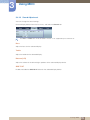
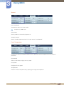
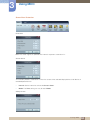
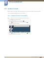
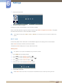
PIP
Basic information required to adjust PIP will appear in the menu screen.
z
PIP will be disabled when Video Wall is ON.
z
Note that Picture Size is disabled when PIP is ON.
PIP Size
View the PIP Size of the current display.
PIP Source
Select a PIP input source.
Sound Select
Select and enable the sound from either the primary screen or secondary screen.
Channel
The channel can be changed if PIP Source is TV.
3 Using MDC
79
3
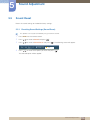
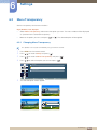
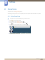
Using MDC
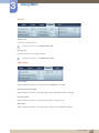
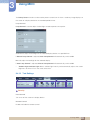
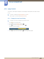
General
User Auto Color
Automatically adjust the screen colors.
Available only in PC mode.
Auto Power
Set the product to automatically power on.
Standby Control
Set the standby mode to activate if an input source is not detected.
Fan & Temperature
Configure the settings required to detect the fan speed and internal temperature for the product's
protection.
Fan Control
Select a method to configure the fan speed.
Fan Speed
Configure the fan speed.
Temperature
Detect the internal temperature by specifying the range of temperature.
3 Using MDC
80
3
Using MDC
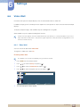
Security
Safety Lock
Lock the on-screen menus.
To unlock the menus, set Safety Lock to Off.
Button Lock
Lock the buttons on the display device.
To unlock the buttons, set Button Lock to Off.
OSD Display
Source OSD
Select whether to display a message when the Source is changed.
Not Optimum Mode OSD
Select whether to display a message when a non-compatible mode is selected.
No Signal OSD
Select whether to display a message when there is no input signal.
MDC OSD
Select whether to display a message when settings are changed by the MDC.
3 Using MDC
81
3
Using MDC
Time
Clock Set
Change the current time on the selected display device according to the time set on a PC.
If the time is not set on the display device, null values will be displayed.
Timer
z
On Time: Set the time to power on the selected display device.
z
Off Time: Set the time to power off the selected display device.
z
Volume: Specify the volume of the display device when it is powered on by On Time.
z
Source: Specify the input source of the display device when it is powered on by On Time.
z
Holiday: The Holiday Management settings can be applied to the Timer.
z
Repeat : Specify the period for which you want to repeat the selected Timer.
3 Using MDC
82
3
Using MDC
Once: Activate the timer only one time.
EveryDay: Activate the timer every day.
Mon~Fri: Activate the timer from Monday through Friday.
Mon~Sat: Activate the timer on Saturdays and Sundays.
Manual: Customize days of the week.
The checkboxes to select days of the week below Repeat are enabled only if Manual is selected.
Holiday Management
Holiday Management allows you to prevent devices that are set to be powered on by the Timer from
turning on at a specified date.
The Holiday Management function can be enabled or disabled in the Timer settings menu.
z
Add: You can specify holidays:
Click the Add button in the Holiday Management window.
z
Delete: Delete holidays. check the corresponding checkboxes and click this button.
z
List of holidays: View a list of holidays you have added.
3 Using MDC
83
3
Using MDC
Screen Burn Protection
Pixel Shift
Move the screen slightly at specified time intervals to prevent screen burn-in.
Screen Saver
This function prevents screen burn-in when the screen of the selected display device is left idle for an
extended period of time.
z
Interval: Set the interval to activate the Screen Saver.
z
Mode: The Time setting can vary for each Mode.
Safety Screen
3 Using MDC
84
3
Using MDC
The Safety Screen function can be used to prevent screen burn-in when a stationary image displays on
the screen of a display device for an extended period of time.
Lamp Control
Lamp Control is used to adjust the backlight to reduce power consumption.
Automatically adjust the backlight of the selected display device at a specified time.
If Manual Lamp Control is adjusted, Auto Lamp Control will automatically switch to Off.
Manually adjust the backlight for the selected display.
If Auto Lamp Control is adjusted, Manual Lamp Control will automatically switch to Off.
Ambient Light: Ambient Light detects ambient light intensity and automatically adjusts the screen
z
brightness of all the LFDs in the same serial chain.
3.4.12 Tool Settings
1
1
2
3
4
Security
Panel Control
Turn on or off the screen of a display device.
Remote Control
Enable or disable the remote control.
3 Using MDC
85
3
Using MDC
2
Reset
Reset Picture
Reset the screen settings.
Reset Sound
Reset the sound settings.
Reset System
Reset the system settings.
Reset All
Reset the screen, sound and system settings at the same time.
3
Edit Column
Select the items you want to display in the list of sets.
4
Information
View the program information.
3 Using MDC
86
3
Using MDC
3.4.13 Other Functions
Resizing a Window
Place the mouse pointer on a corner of the program window. An arrow will appear. Move the arrow to
customize the size of the program window.
3 Using MDC
87
3
Using MDC
Group Management
Creating Groups
Create groups and manage the list of sets on a group basis.
Duplicate group names cannot be used.
1
Right-click and select Group>Edit in the display device list section on the left side of the program
window.
2
In the Edit Group window displayed, click Add on the same level or Add on the sub level.
z
Add on the same level: Create a group on the same level as the selected group.
The Add on the same level button is enabled only if at least one group is created.
3 Using MDC
88
3
Using MDC
z
3
Add on the sub level: Create a sub-group under the selected group.
Enter the group name.
Deleting Groups
1
2
Select a group name, and click Edit.
3
Click Yes. The group will be deleted.
In the Edit Group window displayed, click Delete.
Renaming Groups
1
2
Select a group name, and click Edit.
3
If a cursor appears in the old group name, enter a new group name.
In the Edit Group window displayed, click Rename.
3 Using MDC
89
3
Using MDC
Schedule Management
Creating Schedules
Create and register a schedule on a group basis.
1
Click All Schedule List in the schedule section on the left side of the program window. The Add
button will be enabled in the middle.
2
Click the Add button. The Add Schedule window will appear.
3 Using MDC
90
3
Using MDC
3
Click Add below the Device Group item, and select the group you want to add a schedule to.
4
Select Date&Time/Action and click OK. The schedule will be added and a list of schedules will
appear in the set list window.
z
Device Group: Select a group.
z
Date&Time
z
Instant Execution: Run the schedule immediately.
Timer : Set the date, time and interval to run the schedule.
Action: Select a function that will activate at the specified time and interval.
Schedule Modification
To modify a schedule, select the schedule and click Edit.
Deleting a Schedule
To delete a schedule, select the schedule and click Delete.
3 Using MDC
91
3
Using MDC
3.4.14 Troubleshooting Guide
Issue
The display you want to control
does not appear on the system
information chart.
Solution
1.
Check the connection of the RS232C cable (check that the
cable is properly connected to appropriate serial port).
2.
Check that another display with a duplicate ID is not
connected. Connecting displays with a duplicate ID can
cause the displays not to be shown due to data collision.
3.
Check that the display ID is within the range of 0 and 99.
(Change the ID using the Display menu.)
For a display that supports the ID in a range of 0 to 99,
the ID should be set between 0 and 99.
The display you want to control
does not appear on the other
Control Info Grids.
Check that the display is powered on. (See the power status in
the system information chart.)
The following message appears
repeatedly.
Check that the display you want to control is selected.
Displays power on or off at different
time from one another even though
On Time or Off Time is set.
Adjust the time on the PC to synchronize the time between the
connected displays.
The remote control does not work.
The remote control may not work if the RS-232C cable is
removed or the program is closed abnormally while the Remote
Control function is Disable. To resolve this, run the program
again and set Remote Control to Enable.
Ensure you select the input source the display is connected to.
This program may malfunction sometimes due to a communication problem between the PC and
display or electromagnetic waves emitted from nearby electronic devices.
3 Using MDC
92
3
Using MDC
How display properties are shown when multiple displays are used
1
2
3
When no display is selected: The default value is displayed.
When one display is selected: Settings for the selected display are displayed.
When two displays are selected (e.g. in sequence of ID 1 and ID 3): The settings for ID 1 are
displayed before the settings for ID 3.
4
When the All+Select checkbox is checked and all displays are selected: The default settings are
displayed.
3 Using MDC
93
4
Screen Adjustment
Configure the Picture settings (Brightness, Color Tone, etc.).
z
The layout of the Picture menu options may vary depending on the product.
z
The available options in the Picture menu depend on the selected input source and the settings in
Edit Name. (Refer to page 57 for details about Edit Name.)
z
To use TV, connect a TV tuner box to the product.
Refer to page 55 for details about connecting to a TV.
4.1
Mode
Select a picture mode (Mode) suitable for the environment where the product will be used.
This option is available when Dynamic Contrast is set to Off.
(Refer to page 111 for details about Dynamic Contrast)
4.1.1 Changing the Picture Mode
This product can only be controlled by using the remote control.
1
2
3
Press MENU on the remote control.
Press
/
to move to Picture and press [
Press
/
to move to Mode and press [
].
].
Different Mode options are displayed depending on the current input source:
If the input source is PC or DVI:
M o d e
I n f o r m a t i o n
A d v e r t i s e m e n t
C u s t o m
M o v e
E n t e r
R e t u r n
z
Information: This mode reduces eye fatigue and is suitable for displaying information to the public.
z
Advertisement: This mode is suitable for displaying video content and indoor/outdoor
advertisements.
z
Custom: Customize Contrast and Brightness as required.
1
Press
/
to move to the option you want and press [
].
The selected option will be applied.
4 Screen Adjustment
94
4
Screen Adjustment
If the input source is AV, Component or TV:
M o d e
D y n a m i c
S t a n d a r d
M o v i e
C u s t o m
M o v e
E n t e r
R e t u r n
z
Dynamic: This mode is suitable when the ambient light is bright.
z
Standard : This mode is generally suitable for any environment.
z
Movie: This mode reduces eye fatigue.
z
Custom: Customize Contrast and Brightness as required.
1
Press
/
to move to the option you want and press [
].
The selected option will be applied.
4 Screen Adjustment
95
4
4.2
Screen Adjustment
Custom
Customize Tint under Picture.
z
Changing any setting under Custom will change the Mode setting to Custom.
z
This function is available when Dynamic Contrast is set to Off.
(Refer to page 111 for details about Dynamic Contrast)
4.2.1 Configuring the Custom Settings
This product can only be controlled by using the remote control.
1
2
3
Press MENU on the remote control.
Press
/
to move to Picture and press [
Press
/
to move to Custom and press [
].
].
Different Custom options are displayed depending on the current input source:
If the input source is PC or DVI:
C u s t o m
C o n t r a s t
100
B r i g h t n e s s
100
S h a r p n e s s
50
G a m m a
M o v e
z
:
E n t e r
N a t u r a l
R e t u r n
Contrast
Adjust the contrast between the objects and background. (Range: 0~100)
A higher value will increase the contrast to make the object appear clearer.
z
Brightness
Adjust the general brightness of the picture. (Range: 0~100)
A higher value will make the picture appear brighter.
z
Sharpness
Make the outline of objects more clear or blurry. (Range: 0~100)
A higher value will make the outline of objects clearer.
4 Screen Adjustment
96
4
Screen Adjustment
z
Gamma(Natural/Mode1/Mode2/Mode3)
Adjust the mid-range brightness (Gamma) of the picture.
Natural displays the original picture. Mode1 displays the picture brighter than Natural mode.
Mode2 displays the screen darker than Mode1. Mode3 displays dark parts darker and bright parts
brighter.
1
Press
/
to move to the option you want and press [
]. A window will appear where you can
adjust the value for the selected option.
100
C o n t r a s t
M o v e
2
Press
/
A d j u s t
to adjust the value and press [
R e t u r n
]. The change will be applied.
4 Screen Adjustment
97
4
Screen Adjustment
If the input source is AV, Component or TV:
C u s t o m
C o n t r a s t
100
B r i g h t n e s s
45
S h a r p n e s s
50
C o l o r
50
T i n t
M o v e
z
G r e e n 50 R e d 50
E n t e r
R e t u r n
Contrast
Adjust the contrast between the objects and background. (Range: 0~100)
A higher value will increase the contrast to make the object appear clearer.
z
Brightness
Adjust the general brightness of the picture. (Range: 0~100)
A higher value will make the picture appear brighter.
z
Sharpness
Make the outline of objects more clear or blurry. (Range: 0~100)
A higher value will make the outline of objects clearer.
z
Color
Increase or decrease the color intensity. (Range: 0~100)
A higher value will increase the color intensity.
z
Tint
Adjust the intensity of the red and green colors. (Range: 0~100)
Increasing the red level will make the red color more prominent in the picture. Increasing the green
level will make the green color more prominent in the picture.
1
Press
/
to move to the option you want and press [
]. A window will appear where you can
adjust the value for the selected option.
100
C o n t r a s t
M o v e
2
Press
/
A d j u s t
to adjust the value and press [
R e t u r n
]. The change will be applied.
4 Screen Adjustment
98
4
4.3
Screen Adjustment
Color Tone
Adjust the general color tone of the picture.
z
This function is available when Dynamic Contrast is set to Off.
(Refer to page 111 for details about Dynamic Contrast)
z
Changing any setting under Color Tone will change the Mode setting to Custom.
4.3.1 Configuring the Color Tone Settings
This product can only be controlled by using the remote control.
1
2
3
Press MENU on the remote control.
Press
/
to move to Picture and press [
].
Press
/
to move to Color Tone and press [
].
Different Color Tone options are displayed depending on the current input source:
If the input source is PC or DVI:
C o l o r T o n e
O f f
C o o l
N o r m a l
W a r m
C u s t o m
M o v e
1
Press
/
E n t e r
R e t u r n
to move to the option you want and press [
].
The selected option will be applied.
If the input source is AV, Component or TV:
C o l o r T o n e
O f f
C o o l 2
C o o l 1
N o r m a l
W a r m 1
W a r m 2
M o v e
1
Press
/
E n t e r
R e t u r n
to move to the option you want and press [
].
The selected option will be applied.
4 Screen Adjustment
99
4
4.4
Screen Adjustment
Color Control
Change the color settings for the picture by adjusting the Red, Green and Blue values. (Range: 0~100)
A higher value will increase the intensity of the selected color.
z
This option is available when the input source is PC or DVI.
z
This function is not available when Color Tone is set to Off. To enable the function, Dynamic
Contrast must be set to Off.
(Refer to page 99 and page 111 for details about Color Tone and Dynamic Contrast.)
4.4.1 Configuring the Color Control Settings
This product can only be controlled by using the remote control.
1
2
3
Press MENU on the remote control.
Press
/
to move to Picture and press [
].
Press
/
to move to Color Control and press [
].
The following screen will appear.
C o l o r C o n t r o l
R e d
50
G r e e n
50
B l u e
50
M o v e
4
Press
/
R e t u r n
E n t e r
to move to the option you want and press [
].
A window will appear where you can adjust the value for the selected option.
50
R e d
M o v e
5
Press
/
A d j u s t
to adjust the value and press [
R e t u r n
].
The change will be applied.
4 Screen Adjustment
100
4
4.5
Screen Adjustment
Color Temp.
Adjust the color temperature (Red/Green/Blue). (Range: 5000K–15000K)
This function is available when Dynamic Contrast and Color Tone are set to Off.
(Refer to page 99 and page 111 for details about Color Tone and Dynamic Contrast.)
4.5.1 Configuring the Color Temp. Settings
This product can only be controlled by using the remote control.
1
2
3
Press MENU on the remote control.
Press
/
to move to Picture and press [
].
Press
/
to move to Color Temp. and press [
].
The following screen will appear.
4
Press
/
to adjust the value and press [
C o l o r T e m p .
A d j u s t
]. The change will be applied.
10000K
R e t u r n
4 Screen Adjustment
101
4
4.6
Screen Adjustment
Image Lock
Enhance the picture quality by removing noise (static) such as flickering and shaking.
This option is available when the input source is PC.
4.6.1 Configuring the Image Lock Settings
This product can only be controlled by using the remote control.
1
2
3
Press MENU on the remote control.
Press
/
to move to Picture and press [
].
Press
/
to move to Image Lock and press [
].
The following screen will appear.
I m a g e L o c k
C o a r s e
2205
F i n e
50
V - P o s i t i o n
50
M o v e
z
100
H - P o s i t i o n
R e t u r n
E n t e r
Coarse
Remove vertical noise (stripes) on the screen.
If the screen is in a different position after the frequency is adjusted using Coarse, move the
screen to the center by using the H-Position/V-Position menu.
z
Fine
Remove horizontal noise (stripes) on the screen.
If noise is not completely removed after Fine adjustment, adjust the frequency using Coarse
until noise is minimized and then adjust using Fine again.
z
H-Position
Adjust the screen position. The screen can be moved left or right.
z
V-Position
Adjust the screen position. The screen can be moved up or down.
4
5
Press
/
to move to the option you want and press [
Press
/
to adjust the value and press [
].
]. The change will be applied.
4 Screen Adjustment
102
4
4.7
Screen Adjustment
Auto Adjustment
Automatically adjust the Coarse, Fine, H-Position and V-Position settings.
This function can be used to automatically detect and remove noise on the screen and correct the screen
position.
This function will automatically run if the screen resolution is changed.
This option is available when the input source is PC.
4.7.1 Configuring the Auto Adjustment Settings
This product can only be controlled by using the remote control.
1
2
3
4
Press MENU on the remote control.
Press
/
to move to Picture and press [
].
Press
/
to move to Auto Adjustment and press [
].
The screen settings will automatically be adjusted.
4 Screen Adjustment
103
4
4.8
Screen Adjustment
Signal Balance
This function is used to supplement a weak RGB signal being transmitted through a long cable.
This function is available when the input source is PC and Dynamic Contrast is set to Off.
(Refer to page 111 for details about Dynamic Contrast)
4.8.1 Configuring the Signal Balance Settings
This product can only be controlled by using the remote control.
1
2
3
Press MENU on the remote control.
Press
/
to move to Picture and press [
].
Press
/
to move to Signal Balance and press [
].
The following screen will appear.
S i g n a l B a l a n c e
S i g n a l B a l a n c e
:
O f f
S i g n a l C o n t r o l
M o v e
4
Press
/
E n t e r
R e t u r n
to move to the option you want and press [
].
The selected option will be applied.
5
Press
/
to move to Signal Control and press [
].
The following screen will appear.
S i g n a l C o n t r o l
R-Gain
50
G-Gain
50
B-Gain
50
R-Offset
50
G-Offset
50
B-Offset
50
M o v e
E n t e r
R e t u r n
Signal Control is enabled when Signal Balance is set to On.
4 Screen Adjustment
104
4
Screen Adjustment
6
Press
/
to move to the option you want and press [
].
The following screen will appear.
50
R - G a i n
M o v e
A d j u s t
R e t u r n
Specify the RGB (Red/Green/Blue) Gain and Offset values. R-Gain, G-Gain and B-Gain adjust the
level of red, green and blue colors in the brighter parts of the screen (range: 0–100). R-Offset,
G-Offset and B-Offset adjust the level of red, green and blue colors in the darker parts of the
screen (range: 0–100). A higher value will increase the level of the selected color.
7
Press
/
to adjust the value and press [
]. The change will be applied.
4 Screen Adjustment
105
4
4.9
Screen Adjustment
Size
Change the picture size.
4.9.1 Changing the Picture Size
This product can only be controlled by using the remote control.
1
2
3
Press MENU on the remote control.
Press
/
to move to Picture and press [
Press
/
to move to Size and press [
].
].
Different Size options are displayed depending on the current input source:
If the input source is PC or DVI:
S i z e
1 6 : 9
4 : 3
M o v e
z
E n t e r
R e t u r n
16:9: Display images with an aspect ratio of 16:9. Suitable for viewing DVD content or widescreen
broadcasts.
z
4:3: Display images with an aspect ratio of 4:3. Suitable for viewing video content or standard
broadcasts.
1
Press
/
to move to the option you want and press [
].
The selected option will be applied.
4 Screen Adjustment
106
4
Screen Adjustment
If the input source is AV or Component:
S i z e
16:9
Z o o m 1
Z o o m 2
4:3
S c r e e n F i t
C u s t o m
M o v e
z
E n t e r
R e t u r n
16:9: Display images with an aspect ratio of 16:9. Suitable for viewing DVD content or widescreen
broadcasts.
z
Zoom1 : Enlarge the 16:9 aspect ratio vertically.
z
Zoom2 : Enlarge the Zoom 1 screen vertically.
z
4:3: Display images with an aspect ratio of 4:3. Suitable for viewing video content or standard
broadcasts.
z
Screen Fit
Display images in the original aspect ratio. This option is enabled when the input source is
Component and the video signal is 1080i/p.
z
Custom: Customize the picture size.
1
Press
/
to move to the option you want and press [
].
The selected option will be applied.
z
If Screen Fit is selected, the picture may be cut off or a corrupted screen may be displayed
depending on the current input source.
z
Zoom1 and Zoom2 are not enabled with HD signals (1080i/p, 720p, 768p).
z
If Zoom1 or Zoom2 is selected, the H-Position/V-Position settings for the enlarged screen can
be initialized. (The original size would be restored.)
4 Screen Adjustment
107
4
Screen Adjustment
4.10 Digital NR
Improve the picture quality by minimizing noise (static) on the screen.
z
This option is available when the input source is AV, Component or TV.
z
Some resolutions do not support Digital NR.
4.10.1 Enabling Digital NR
This product can only be controlled by using the remote control.
1
2
3
Press MENU on the remote control.
Press
/
to move to Picture and press [
].
Press
/
to move to Digital NR, and press [
].
The following screen will appear.
D i g i t a l N R
O f f
O n
M o v e
4
Press
/
E n t e r
R e t u r n
to move to the option you want and press [
].
The selected option will be applied.
4 Screen Adjustment
108
4
Screen Adjustment
4.11 HDMI Black Level
If you use the product by connecting to a DVD player or set-top box with a DVI cable, the contrast and
color may degrade and the picture may be darker. If this is the case, correct the degraded picture quality
using HDMI Black Level. (Normal/Low)
This option is available when a source device that has an HDMI port is connected and the input source
is set to DVI.
4.11.1 Configuring the HDMI Black Level Settings
This product can only be controlled by using the remote control.
1
2
3
Press MENU on the remote control.
Press
/
to move to Picture and press [
].
Press
/
to move to HDMI Black Level and press [
].
The following screen will appear.
H D M I B l a c k L e v e l
N o r m a l
L o w
M o v e
E n t e r
R e t u r n
z
Normal: Set the brightness (darkness) of the darkest parts of the screen to Normal.
z
Low: Set the brightness (darkness) of the darkest parts of the screen to be brighter than
Normal.
4
Press
/
to move to the option you want and press [
].
The selected option will be applied.
4 Screen Adjustment
109
4
Screen Adjustment
4.12 Film Mode
Improve the picture quality to enhance the viewing experience when watching a movie.
z
This option is available when the input source is AV, Component or TV.
z
This option is only available when Interlace mode is selected as scanning mode under HDMI mode.
It is not available in progressive scanning mode.
z
Subtitles may appear distorted when this function is active.
4.12.1 Enabling Film Mode
This product can only be controlled by using the remote control.
1
2
3
Press MENU on the remote control.
Press
/
to move to Picture and press [
].
Press
/
to move to Film Mode and press [
].
The following screen will appear.
F i l m M o d e
O f f
O n
M o v e
4
Press
/
E n t e r
R e t u r n
to move to the option you want and press [
].
The selected option will be applied.
4 Screen Adjustment
110
4
Screen Adjustment
4.13 Dynamic Contrast
Maintain optimum contrast by automatically adjusting the contrast between objects and the background.
You can enable or disable Dynamic Contrast. (Off/On)
4.13.1 Changing the Dynamic Contrast Setting
This product can only be controlled by using the remote control.
1
2
3
Press MENU on the remote control.
Press
/
to move to Picture and press [
].
Press
/
to move to Dynamic Contrast and press [
].
The following screen will appear.
D y n a m i c C o n t r a s t
O f f
O n
M o v e
4
Press
/
E n t e r
R e t u r n
to move to the option you want and press [
].
The selected option will be applied.
4 Screen Adjustment
111
4
Screen Adjustment
4.14 Lamp Control
This function is used to adjust the brightness of the backlight to reduce power consumption. (Range:
0~100)
This option is available when Dynamic Contrast is set to Off.
(Refer to page 111 for details about Dynamic Contrast)
4.14.1 Changing the Lamp Control Setting
This product can only be controlled by using the remote control.
1
2
3
Press MENU on the remote control.
Press
/
to move to Picture and press [
].
Press
/
to move to Lamp Control and press [
].
The following screen will appear.
L a m p
A d j u s t
4
Press
/
100
C o n t r o l
to adjust the value and press [
R et u r n
]. The change will be applied.
4 Screen Adjustment
112
4
Screen Adjustment
4.15 Picture Reset
Restore the default picture settings.
4.15.1 Activating Picture Reset
This product can only be controlled by using the remote control.
1
2
3
Press MENU on the remote control.
Press
/
to move to Picture and press [
].
Press
/
to move to Picture Reset and press [
].
The following screen will appear.
P i c t u r e
R e s e t
A d j u s t
4
Press
/
N o
Y e s
R e t u r n
to select Yes or No and press [
].
The selected option will be applied.
4 Screen Adjustment
113
5
5.1
Sound Adjustment
Configure the sound (Sound) settings for the product.
Mode
Select a sound mode (Mode) suitable for the environment where the product will be used.
5.1.1 Changing the Mode Setting
This product can only be controlled by using the remote control.
1
2
3
Press MENU on the remote control.
Press
/
to move to Sound and press [
Press
/
to move to Mode and press [
].
].
The following screen will appear.
M o d e
S t a n d a r d
M u s i c
M o v i e
S p e e c h
C u s t o m
M o v e
4
E n t e r
R e t u r n
z
Standard: Provides sound suitable for any type of content.
z
Music: Provides sound close to the original experience.
z
Movie: Provides a grand sound experience.
z
Speech: Hear voices clearly.
z
Custom: Customize the sound as required.
Press
/
to move to the option you want and press [
].
The selected option will be applied.
5 Sound Adjustment
114
5
5.2
Sound Adjustment
Custom
You can customize the sound settings.
5.2.1 Configuring the Custom Settings
This product can only be controlled by using the remote control.
1
2
3
Press MENU on the remote control.
Press
/
to move to Sound and press [
].
Press
/
to move to Custom and press [
].
The following screen will appear.
C u s t o m
B a s s
9
T r e b l e
40
B a l a n c e
M o v e
4
L 50
R 50
R e t u r n
E n t e r
z
Bass: Adjust the bass level. (Range: 0~100)
z
Treble: Adjust the treble level. (Range: 0~100)
z
Balance : Balance the sound by adjusting the volume between the left and right speakers.
Press
/
to move to the option you want and press [
].
A window will appear where you can adjust the value for the selected option.
9
B a s s
M o v e
5
Press
/
A d j u s t
to adjust the value and press [
R e t u r n
]. The change will be applied.
z
With some products, sound may be heard even when the volume is set to 0.
z
Changing any setting under Custom will change the Mode settings to Custom.
5 Sound Adjustment
115
5
5.3
Sound Adjustment
Auto Volume
This function can be used to adjust the volume to an appropriate level if the volume is particularly higher
or lower than usual.
5.3.1 Changing the Auto Volume Setting
This product can only be controlled by using the remote control.
1
2
3
Press MENU on the remote control.
Press
/
to move to Sound and press [
].
Press
/
to move to Auto Volume and press [
].
The following screen will appear.
A u t o V o l u m e
O f f
O n
M o v e
4
Press
/
E n t e r
R e t u r n
to move to the option you want and press [
].
The selected option will be applied.
5 Sound Adjustment
116
5
5.4
Sound Adjustment
SRS TS XT
You can enjoy the grand and vivid sound quality of 5.1-channel speakers using two speakers.
TruSurround (TS) XT provides realistic surround sound through any type of 2-channel speaker system
such as internal speakers. It is also fully compatible with all multi-channel formats.
5.4.1 Setting SRS TS XT
This product can only be controlled by using the remote control.
1
2
3
Press MENU on the remote control.
Press
/
to move to Sound and press [
].
Press
/
to move to SRS TS XT and press [
].
The following screen will appear.
S R S T S X T
O f f
O n
M o v e
4
Press
/
E n t e r
R e t u r n
to move to the option you want and press [
].
The selected option will be applied.
5 Sound Adjustment
117
5
5.5
Sound Adjustment
Sound Reset
Return the sound settings to the default factory settings.
5.5.1 Resetting Sound Settings (Sound Reset)
This product can only be controlled by using the remote control.
1
2
3
Press MENU on the remote control.
4
Press
/
to move to Sound and press [
].
Press
/
to move to Sound Reset and press [
Press
/
to move to the option you want and press [
]. The following screen will appear.
].
The selected option will be applied.
5 Sound Adjustment
118
6
6.1
Settings
You can configure additional settings as required.
Language
Set the menu language.
z
English / Deutsch / Español / Français / Italiano / Svenska / / Português
Türkçe / ㅔԧЁ᭛/ ᧯խ֮ / ᣣᧄ⺆ / ֝ઘ
A change to the language setting will only be applied to the onscreen menu display. It will not be applied
to other functions on your PC.
6.1.1 Changing the Language
This product can only be controlled by using the remote control.
1
2
3
4
Press MENU on the remote control.
Press
/
to move to Setup and press [
].
Press
/
to move to Language and press [
Press
/
to move to the language you want and press [
].
].
L a n g u a g e
E n g l i s h
D e u t s c h
E s p a ñ o l
F r a n ç a i s
I t a l i a n o
S v e n s k a
M o v e
5
E n t e r
R e t u r n
Menus will be displayed in the new language that was changed.
6 Settings
119
6
6.2
Settings
Time
You can configure Clock Set or Sleep Timer. You can also set the product to automatically turn on or off
at a specified time using the Timer function.
6.2.1
Clock Set
Set the current time.
Changing the Setting for Clock Set
This product can only be controlled by using the remote control.
1
2
3
4
5
Press MENU on the remote control.
Press
/
to move to Setup and press [
].
Press
/
to move to Time and press [
Press
/
to move to Clock Set and press [
].
].
In the displayed Clock Set window, set the current time using the direction keys.
C l o c k S e t
M o n t h
D a y
Y e a r
--
--
----
H o u r
M i n u t e
a m / p m
--
--
a m
M o v e
6
Press [
] or [
E n t e r
R e t u r n
] when all settings are complete. The settings will be applied.
6 Settings
120
6
Settings
6.2.2
Sleep Timer
Set the product to automatically power on or off after a specified period of time.
You can select the time to turn off the product from 30, 60, 90, 120, 150 or 180 minutes from the current
time.
Setting Sleep Timer
This product can only be controlled by using the remote control.
1
2
3
4
5
Press MENU on the remote control.
Press
/
to move to Setup and press [
].
Press
/
to move to Time and press [
Press
/
to move to Sleep Timer, and press [
Press
/
to move to the time you want and press [
].
].
].
S l e e p T i m e r
Off
30
60
90
120
150
180
M o v e
6
E n t e r
R e t u r n
Sleep Timer will activate after the selected time.
6 Settings
121
6
Settings
6.2.3
Timer1 / Timer2 / Timer3
Set the product to automatically power on or off at a specified time.
The product will power on, preserving the same volume and input source settings as when it powered
off.
Setting Timer
This product can only be controlled by using the remote control.
1
2
3
4
5
Press MENU on the remote control.
Press
/
to move to Setup and press [
].
Press
/
to move to Time and press [
Press
/
to move to Timer1, Timer2 or Timer3 and press [
].
].
In the displayed Timer window, set the timer using the direction keys.
T i m e r 1
O n T i m e
12
00
a m
O f f
O f f T i m e
12
00
a m
O f f
V o l u m e
1 0
R e p e a t
A V
H o l i d a y
P C
D o n ' t A p p l y
Tue
S u n
M o n
T u e
W e d
T h u
F r i
S a t
O n c e
M o v e
6
Press [
] or [
A d j u s t
R e t u r n
] when all settings are complete. The settings will be applied.
z
Timer will only activate when the current time is set (Clock Set).
z
Holiday(Apply/Don't Apply) : When Repeat is applied to the timer, the Holiday option can be
used to set the timer not to activate on specified days of the week.
z
The day selector boxes at the bottom will be disabled if Holiday is set to Don't Apply.
6 Settings
122
6
Settings
6.2.4
Holiday Management
Timer will be disabled during a period specified as a holiday.
Setting Holiday Management
This product can only be controlled by using the remote control.
1
2
3
4
Press MENU on the remote control.
Press
/
to move to Setup and press [
].
Press
/
to move to Time and press [
Press
/
to move to Holiday Management and press [
].
].
H o l i d a y M a n a g e m e n t
02/01~02/28
A d d
D e l e t e S e l e c t e d
D e l e t e A l l
M o v e
z
z
R e t u r n
E n t e r
Add: Specify the period you want to add as a holiday.
Go to the Add menu, and press [
Press
The period will be added to the list of holidays.
/
].
to specify the period and press [
] or [
].
Delete Selected: Delete an item from the list of holidays.
Select an item from the list of holidays and press [
The Delete Selected option will be activated.
Move to Delete Selected and press [
].
]. The message "Delete the selected holidays?"
will appear.
z
Select Yes. The selected holiday will be deleted.
Delete All: Delete all items from the list of holidays.
Select Delete All. The message "Delete all holidays?" will appear.
Select Yes. All holidays will be deleted.
6 Settings
123
6
6.3
Settings
Menu Transparency
Set the transparency for the menu windows:
High, Medium, Low, Opaque
z
Select Menu Transparency and move to the option you want. The menu window will be displayed
as a preview for the selected transparency.
z
Move to the option you want, and press [
] or [
]. The selected option will be applied.
6.3.1 Changing Menu Transparency
This product can only be controlled by using the remote control.
1
2
3
4
Press MENU on the remote control.
Press
/
to move to Setup and press [
].
Press
/
to move to Menu Transparency and press [
Press
/
to select the option you want and press [
].
].
M e n u T r a n s p a r e n c y
H i g h
M e d i u m
L o w
O p a q u e
M o v e
5
R e t u r n
E n t e r
The selected option will be applied.
M e n u T r a n s p a r e n c y
M e n u T r a n s p a r e n c y
H i g h
H i g h
M e d i u m
M e d i u m
L o w
L o w
O p a q u e
O p a q u e
M o v e
E n t e r
R e t u r n
M e n u T r a n s p a r e n c y
M o v e
R e t u r n
E n t e r
R e t u r n
M e n u T r a n s p a r e n c y
H i g h
H i g h
M e d i u m
M e d i u m
L o w
L o w
O p a q u e
O p a q u e
M o v e
E n t e r
E n t e r
R e t u r n
M o v e
6 Settings
124
6
6.4
Settings
Safety Lock
Lock the product in order to prevent the product from malfunction or unintended changes to the settings,
or change the PIN used for locking the product.
6.4.1
Change PIN
Change the PIN required to lock the product.
The default PIN is "0000."
Select Change PIN to open a PIN input field.
Changing the PIN (Change PIN)
This product can only be controlled by using the remote control.
1
2
3
4
5
Press MENU on the remote control.
Press
/
to move to Setup and press [
].
Press
/
to move to Safety Lock and press [
].
Press
/
to move to Change PIN and press [
].
Enter the current PIN in the displayed PIN input field.
C h a n g e P I N
E n t e r P I N
0..9 A d j u s t
6
E n t e r
R e t u r n
E n t e r
R e t u r n
Enter a new PIN.
C h a n g e P I N
E n t e r n e w P I N .
0..9 A d j u s t
6 Settings
125
6
Settings
7
Re-enter the new PIN.
C h a n g e P I N
C o n f i r m n e w P I N .
0..9 A d j u s t
8
R e t u r n
E n t e r
The PIN has been changed.
Entering the current PIN will display a new PIN input window.
Enter a new PIN and enter it again to confirm. The message "PIN is changed successfully." will appear
to indicate that the PIN has successfully been changed.
If you forgot the PIN, press INFO -> EXIT -> MUTE on the remote control to restore the default PIN
(0000).
6.4.2
Lock
Prevent the product from malfunction or unintended changes to the settings with the Lock feature.
Select Lock and enter the PIN to activate lock mode.
To deactivate Lock mode, press any key and enter the PIN.
Setting Lock
This product can only be controlled by using the remote control.
1
2
3
4
5
Press MENU on the remote control.
Press
/
to move to Setup and press [
].
Press
/
to move to Safety Lock and press [
Press
/
to move to Lock and press [
].
].
Enter your PIN in the displayed Lock On window.
L o c k O n
E n t e r P I N
0..9 A d j u s t
6
E n t e r
R e t u r n
Lock mode will activate.
Under Lock mode, all controls on the product are disabled until you unlock by entering the PIN.
6 Settings
126
6
6.5
Settings
Energy Saving
Save power with the Energy Saving feature.
While Energy Saving mode is active, the product power consumption will be controlled to save power.
6.5.1 Setting Energy Saving
This product can only be controlled by using the remote control.
1
2
3
4
Press MENU on the remote control.
Press
/
to move to Setup and press [
].
Press
/
to move to Energy Saving and press [
Press
/
to select the option you want and press [
].
].
E n e r g y S a v i n g
O f f
O n
M o v e
5
E n t e r
R e t u r n
The selected option will be applied.
6 Settings
127
6
6.6
Settings
Video Wall
Customize the layout of multiple displays that are connected to form a video wall.
In addition, display part of a whole picture or repeat the same picture on each of the connected multiple
displays.
To display multiple images, refer to MDC Help or the MagicInfo user guide.
Some models may not support the MagicInfo function.
If more than four displays are connected horizontally and vertically, it is recommended that you use an
input resolution of XGA (1024 x 768) level or higher to prevent a dark picture due to degradation in the
contrast or color intensity.
6.6.1
Video Wall
You can activate or deactivate Video Wall.
To organize a video wall, select On.
Enabling Video Wall
This product can only be controlled by using the remote control.
1
2
3
4
Press MENU on the remote control.
Press
/
to move to Setup and press [
].
Press
/
to move to Video Wall and press [
Press
/
to select the option you want and press [
].
].
V i d e o W a l l
O f f
O n
M o v e
5
E n t e r
R e t u r n
The selected option will be applied.
6 Settings
128
6
Settings
6.6.2
Format
Select a format to display images on multiple displays.
z
Full : Display images in full screen.
z
Natural : Display images at the original resolution without enlarging or reducing.
Changing Format
This product can only be controlled by using the remote control.
1
2
3
4
5
Press MENU on the remote control.
Press
/
to move to Setup and press [
].
Press
/
to move to On under Video Wall and press [
Press
/
to move to Format and press [
Press
/
to select the option you want and press [
].
].
].
F o r m a t
F u l l
N a t u r a l
M o v e
6
E n t e r
R e t u r n
The selected option will be applied.
The Screen Position option is only enabled when Video Wall is set to On.
6 Settings
129
6
Settings
6.6.3
Horizontal
This function automatically divides the screen according to the specified number of horizontal displays.
Enter the number of horizontally arranged displays.
The horizontal screen will automatically be divided according to the number entered.
A maximum of 15 displays can be assigned to the horizontal arrangement.
Setting Horizontal
This product can only be controlled by using the remote control.
1
2
3
4
5
Press MENU on the remote control.
Press
/
to move to Setup and press [
].
Press
/
to move to On under Video Wall and press [
Press
/
to move to Horizontal and press [
Press
/
to select a number, and press [
].
].
].
H o r i z o n t a l
1
M o v e
6
E n t e r
R e t u r n
The screen will be divided according to the selected number.
z
The screen can be divided into a maximum of 100 screens (horizontal and vertical screens
multiplied). But, if the horizontal arrangement is set to 15, a maximum of 6 displays can be
assigned to the vertical arrangement. Conversely, if the vertical arrangement is set to 15, a
maximum of 6 displays can be assigned to the horizontal arrangement.
z
The Screen Position option is only enabled when Video Wall is set to On.
6 Settings
130
6
Settings
6.6.4
Vertical
This function automatically divides the screen according to the specified number of vertical displays.
Enter the number of vertically arranged displays.
The vertical screen will automatically be divided according to the number entered.
A maximum of 15 displays can be assigned to the vertical arrangement.
Setting Vertical
This product can only be controlled by using the remote control.
1
2
3
4
5
Press MENU on the remote control.
Press
/
to move to Setup and press [
].
Press
/
to move to On under Video Wall and press [
Press
/
to move to Vertical and press [
].
Press
/
to select a number, and press [
].
].
V e r t i c a l
1
M o v e
6
E n t e r
R e t u r n
The screen will be divided according to the selected number.
z
The screen can be divided into a maximum of 100 screens (horizontal and vertical screens
multiplied). But, if the horizontal arrangement is set to 15, a maximum of 6 displays can be
assigned to the vertical arrangement. Conversely, if the vertical arrangement is set to 15, a
maximum of 6 displays can be assigned to the horizontal arrangement.
z
The Screen Position option is only enabled when Video Wall is set to On.
6 Settings
131
6
Settings
6.6.5
Screen Position
You can customize the arrangement of split screens by moving displays identified with a number using
the Screen Position function.
Select Screen Position to display the arrangement of displays (identified with a number) specified
according to the Horizontal or Vertical settings. To customize the arrangement, move a number (display)
using the direction buttons on the remote control and press [
].
Changing Screen Position
This product can only be controlled by using the remote control.
1
2
3
4
5
Press MENU on the remote control.
Press
/
to move to Setup and press [
].
Press
/
to move to On under Video Wall and press [
Press
/
to move to Screen Position and press [
Press
/
to move a number (display) as required and press [
].
].
].
S c r e e n P o s i t i o n
M o v e
6
E n t e r
R e t u r n
The new arrangement after the change will be displayed.
z
A maximum of 100 displays can be arranged in Screen Position.
z
The Screen Position option is only enabled when Video Wall is set to On.
z
The Screen Position window is only displayed when Horizontal and Vertical are configured.
6 Settings
132
6
6.7
Settings
Safety Screen
This product uses a Safety Screen function to prevent afterimage burn-in on the screen when a
stationary image is displayed for an extended period of time. The Safety Screen function allows you to
configure various settings to protect the screen.
6.7.1
Pixel Shift
Prevent afterimage burn-in by moving pixels slightly at specified intervals.
Setting Pixel Shift
This product can only be controlled by using the remote control.
1
2
3
4
Press MENU on the remote control.
Press
/
to move to Setup and press [
Press
/
to move to Safety Screen and press [
Press
/
to move to Pixel Shift and press [
z
].
].
].
Pixel Shift
Activate or deactivate Pixel Shift.
P i x e l S h i f t
O f f
O n
M o v e
Press
z
/
R e t u r n
E n t e r
to select the option you want and press [
].
Horizontal
Specify how many pixels you want to move horizontally. (Range: 0~4)
H o r i z o n t a l
0
1
2
3
4
M o v e
Press
/
R e t u r n
E n t e r
to select a number, and press [
].
A higher value will minimize the chance of afterimage burn-in but slight flickering may occur.
6 Settings
133
6
Settings
z
Vertical
Specify how many pixels you want to move vertically. (Range: 0~4)
V e r t i c a l
0
1
2
3
4
M o v e
Press
/
R e t u r n
E n t e r
to select a number, and press [
].
A higher value will minimize the chance of afterimage burn-in but slight flickering may occur.
z
Time
Set the time interval to move the specified number of pixels horizontally and vertically.
T i m e
4
A d j u s t
Press
/
m i n
R e t u r n
E n t e r
to select a number, and press [
].
6 Settings
134
6
Settings
6.7.2
Timer
Easily protect the screen by setting the timer to activate the afterimage burn-in prevention mode.
(Bar and Eraser)
Setting Timer
This product can only be controlled by using the remote control.
1
2
3
4
Press MENU on the remote control.
Press
/
to move to Setup and press [
Press
/
to move to Safety Screen and press [
Press
/
to move to Timer and press [
z
].
].
].
Timer
You can enable or disable the timer.
T i m e r
O f f
O n
M o v e
Press
z
/
E n t e r
R e t u r n
to select the option you want and press [
].
Mode
You can select mode from Bar or Eraser.
M o d e
B a r
E r a s e r
M o v e
Press
/
E n t e r
R e t u r n
to select the option you want and press [
].
6 Settings
135
6
Settings
z
Period
You can set the time interval to activate the timer. (Range: 1 to 10 hours)
P e r i o d
1
A d j u s t
Press
z
/
H o u r
R e t u r n
E n t e r
to select a number, and press [
].
Time
You can set the time length you want to activate the timer at a specified interval. (10, 20, 30, 40
or 50 seconds)
T i m e
10
20
30
40
50
M o v e
Press
6.7.3
/
R e t u r n
E n t e r
to select a number, and press [
].
Bar / Eraser
You can manually run the selected screen protection mode.
Setting Bar / Eraser
This product can only be controlled by using the remote control.
1
2
3
4
Press MENU on the remote control.
Press
/
to move to Setup and press [
].
Press
/
to move to Safety Screen and press [
Press
/
to move to Bar or Eraser and press [
].
]. The afterimage burn-in prevention mode will
immediately activate.
5
To deactivate the process and return to the menu screen, press [
].
6 Settings
136
6
Settings
6.7.4
Side Gray
Select the brightness of the grey color for blank parts on the screen. (Off / Light / Dark)
Setting Side Grey
This product can only be controlled by using the remote control.
1
2
3
4
5
6
6.8
Press MENU on the remote control.
Press
/
to move to Setup and press [
].
Press
/
to move to Safety Screen and press [
Press
/
to move to Side Gray and press [
Press
/
to move to the option you want and press [
].
].
].
The selected option will be applied.
Resolution Select
If the picture is not normal even when the resolution of the graphics card is one of the following, you can
optimize the picture quality by selecting the same resolution for the product as the PC using this menu.
Available resolutions: Off / 1024 x 768 / 1280 x 768 / 1360 x 768 / 1366 x 768
6.8.1 Changing the Resolution (Resolution Select)
This product can only be controlled by using the remote control.
1
2
3
4
5
Press MENU on the remote control.
Press
/
to move to Setup and press [
].
Press
/
to move to Resolution Select and press [
Press
/
to move to the option you want and press [
].
].
The selected option will be applied.
The Resolution Select option is only enabled when the input source is PC.
6 Settings
137
6
6.9
Settings
Power On Adjustment
You can set the warm-up time for the screen to turn on after the power button is pressed. (Range: 0 – 50
seconds)
6.9.1 Setting Power On Adjustment
This product can only be controlled by using the remote control.
1
2
3
4
Press MENU on the remote control.
Press
/
to move to Setup and press [
Press
/
to move to Power On Adjustment and press [
Press [
].
], and select a warm-up time using the
/
].
button in the Power On Adjustment
window.
P o w e r O n A d j u s t m e n t
0
A d j u s t
5
E n t e r
s e c
R e t u r n
The configured Power On Adjustment time will be applied.
A warm-up time that is too short may damage the product due to overvoltage.
6 Settings
138
6
Settings
6.10 OSD Rotation
You can rotate and display the menu window in portrait mode when the product is in portrait orientation.
6.10.1 Changing the Menu Orientation (OSD Rotation)
This product can only be controlled by using the remote control.
1
2
3
4
Press MENU on the remote control.
Press
/
to move to Setup and press [
].
Press
/
to move to OSD Rotation and press [
Press
/
to move to the option you want and press [
].
].
O S D R o t a t i o n
L a n d s c a p e
P o r t r a i t
M o v e
5
E n t e r
R e t u r n
The selected option will be applied.
6 Settings
139
6
Settings
6.11 Advanced Settings
You can configure advanced settings for your display.
6.11.1
Temperature
Safeguard the product by using a protection feature that detects the internal temperature.
Configuring Temperature Control
This product can only be controlled by using the remote control.
1
2
3
4
Press MENU on the remote control.
Press
/
to move to Setup and press [
Press
/
to move to Advanced Settings and press [
Press
/
to move to Temperature and press [
z
].
].
].
Temperature Control
This function detects the internal temperature of the product. You can specify the temperature
range that is acceptable.
The default temperature is set to 77 C.
The recommended operating temperature for this product is 75 to 80 C (based on an ambient
temperature of 40 C).
Refer to "page 153" for details about operating environment requirements.
80
T e m p e r a t u r e
A d j u s t
Press
/
R e t u r n
to select a number, and press [
].
The screen will become darker if the current temperature exceeds the specified temperature
limit. If the temperature continues to rise, the product will power off to prevent overheating.
z
Current Temperature
View the current internal temperature.
6 Settings
140
6
Settings
6.11.2
Auto Power
This function automatically turns on the power if the power cable is reconnected or the power switch
[POWER S/W] on the back of the product is switched on. The product must be initially turned off with the
power button on the remote control for this function to be available.
You do not need to press the power button to turn on the product.
Enabling this option will automatically power on the product if the power cable is connected.
Changing the Auto Power Setting
This product can only be controlled by using the remote control.
1
2
3
4
5
Press MENU on the remote control.
Press
/
to move to Setup and press [
].
Press
/
to move to Advanced Settings and press [
Press
/
to move to Auto Power and press [
Press
/
to move to the option you want and press [
].
].
].
A u t o P o w e r
O f f
O n
M o v e
6
E n te r
R e t u r n
The selected option will be applied.
6 Settings
141
6
Settings
6.11.3
User Auto Color
Setting User Auto Color
This product can only be controlled by using the remote control.
1
2
3
4
5
6
Press MENU on the remote control.
Press
/
to move to Setup and press [
].
Press
/
to move to Advanced Settings and press [
Press
/
to move to User Auto Color and press [
Press
/
to move to the option you want and press [
].
].
].
The selected option will be applied.
z
Auto Color
This menu automatically adjusts the picture color to obtain optimum picture quality.
z
Reset
Restore the default color settings.
The User Auto Color option is only enabled when the input source is PC.
6 Settings
142
6
Settings
6.11.4
Standby Control
You can set the screen standby mode to be applied when an input signal is received.
Setting Standby Control
1
2
3
4
5
Press MENU on the remote control.
Press
/
to move to Setup and press [
].
Press
/
to move to Advanced Settings and press [
Press
/
to move to Standby Control and press [
Press
/
to move to the option you want and press [
].
].
].
S t a n d b y C o n t r o l
A u t o
O n
O f f
M o v e
E n t e r
R e t u r n
Auto
z
Power-saving mode will activate if no input signals are detected even though a source device is
connected to the display.
The message "No Signal" will appear if no source device is connected.
On
z
Power-saving mode will activate if no input signals are detected.
Off
z
The message "No Signal" will appear if no input signals are detected.
6
The selected option will be applied.
z
The Standby Control option is only enabled when Source is set to PC or DVI.
z
If "No Signal" is displayed although a source device is connected, check the cable connection.
Refer to page 56 for details about connecting source devices.
6 Settings
143
6
Settings
6.11.5
Lamp Schedule
Setting Lamp Schedule
1
2
3
4
5
6
7
8
z
This product can only be controlled by using the remote control.
z
You must set the clock first.
Press MENU on the remote control.
Press
/
to move to Setup and press [
Press
/
to move to Advanced Settings and press [
Press
/
to move to Lamp Schedule and press [
Press [
], and move to On using the
/
].
].
].
button and press [
].
Configure the schedule settings enabled at the bottom using the direction keys.
Press [
] when all settings are complete.
The selected option will be applied.
6.11.6
OSD Display
Changing the OSD Display Settings
This product can only be controlled by using the remote control.
1
2
3
4
Press MENU on the remote control.
Press
/
to move to Setup and press [
Press
/
to move to Advanced Settings and press [
Press
/
to move to OSD Display and press [
z
].
].
].
Source OSD
S o u r c e O S D
O f f
O n
M o v e
Press
/
E n t e r
R e t u r n
to select the option you want and press [
].
6 Settings
144
6
Settings
z
Not Optimum Mode OSD
N o t O p t i m u m M o d e O S D
O f f
O n
M o v e
Press
z
/
E n t e r
R e t u r n
to select the option you want and press [
].
No Signal OSD
N o S i g n a l O S D
O f f
O n
M o v e
Press
z
/
E n t e r
R e t u r n
to select the option you want and press [
].
MDC OSD
M D C O S D
O f f
O n
M o v e
Press
/
E n t e r
R e t u r n
to select the option you want and press [
].
6 Settings
145
6
Settings
6.12 Setup Reset
This option returns the current settings under Setup to the default factory settings.
6.12.1 Resetting Setup (Setup Reset)
This product can only be controlled by using the remote control.
1
2
3
4
Press MENU on the remote control.
Press
/
to move to Setup and press [
Press
/
to move to Setup Reset and press [
Press
/
to move to the option you want and press [
S e t u p
R e s e t
].
].
N o
Y e s
R e t u r n
A d j u s t
5
].
The selected option will be applied.
6.13 Reset All
This option returns all the current settings for a display to the default factory settings.
6.13.1 Resetting All Settings (Reset All)
This product can only be controlled by using the remote control.
1
2
3
4
Press MENU on the remote control.
Press
/
to move to Setup and press [
Press
/
to move to Reset All and press [
Press
/
to move to the option you want and press [
R e s e t
A l l
Y e s
A d j u s t
5
].
].
].
N o
R e t u r n
The selected option will be applied.
6 Settings
146
7
7.1
Troubleshooting Guide
Requirements Before Contacting Samsung Customer
Service Center
7.1.1 Testing the Product
Before calling Samsung Customer Service Center, test your product as follows. If the problem persists,
contact Samsung Customer Service Center.
Check if your product is operating normally by using the product test function.
If the screen remains blank while the power LED blinks even when the product is correctly connected to
a PC, perform product testing.
1
2
3
4
Power off both the PC and product.
Disconnect all the cables from the product.
Power on the product.
If "No Signal" is displayed, the product is operating normally.
If the screen remains blank, check the PC system, video controller and cable.
7.1.2 Checking the Resolution and Frequency
"Not Optimum Mode" will briefly be displayed if a mode that exceeds a supported resolution is selected
(refer to Supported Resolutions).
7 Troubleshooting Guide
147
7
Troubleshooting Guide
7.1.3 Check the followings.
Installation issue (PC mode)
The screen keeps switching on and off.
Check the cable connection between the
product and PC, and ensure the connection is
secure.
("2.2 Connecting and Using a PC")
Blank spaces are found at the top and bottom
of the screen when an HDMI or HDMI-DVI
cable is connected to the monitor and PC.
Blank spaces on the screen are not caused by
the monitor.
The cause of the problem is the PC or graphics
card, and can be fixed by adjusting the screen
size in the HDMI or DVI option of the graphics
card settings menu.
If the graphics card settings menu has no
option to adjust the screen size, update the
graphics card driver to the latest version.
(Please contact the graphics card or computer
manufacturer for details on how to adjust the
screen settings.)
Screen issue
The power LED is off. The screen will not
switch on.
Make sure that the power cord is connected.
"No Signal" is displayed on the screen (refer to
"Connecting to a PC").
Check that the product is connected correctly
with a cable
("2.2 Connecting and Using a PC")
("2.2 Connecting and Using a PC")
Check that the device connected to the
product is powered on.
"Not Optimum Mode" is displayed.
This message is displayed when a signal from
the graphics card exceeds the product's
maximum resolution and frequency.
Refer to the Standard Signal Mode Table and
set the maximum resolution and frequency
according to the product specifications.
The images on the screen look distorted.
Check the cable connection to the product
("2.2 Connecting and Using a PC")
7 Troubleshooting Guide
148
7
Troubleshooting Guide
Screen issue
The screen is not clear. The screen is blurry.
Adjust Coarse and Fine.
Remove any accessories (video extension
cable, etc) and try again.
Set the resolution and frequency to the
recommended level.
The screen appears unstable and shaky.
There are shadows or ghost images left on the
screen.
Check that the resolution and frequency of the
PC and graphics card are set within a range
compatible with the product. Then, change the
screen settings if required by referring to the
Additional Information on the product menu
and the Standard Signal Mode Table.
The screen is too bright. The screen is too
dark.
Adjust Brightness and Contrast.
Screen color is inconsistent.
Go to Picture and adjust the Color Control
settings.
The colors on the screen have a shadow and
are distorted.
Go to Picture and adjust the Color Control
settings.
White does not really look white.
Go to Picture and adjust the Color Control
settings.
There is no image on the screen and the power
LED blinks every 0.5 to 1 second.
The product is in power-saving mode.
Press any key on the keyboard or move the
mouse to return to the previous screen.
Sound issue
There is no sound.
Check the connection of the audio cable or
adjust the volume
("2.2 Connecting and Using a PC")
Check the volume.
The volume is too low.
Adjust the volume.
If the volume is still low after turning it up to the
maximum level, adjust the volume on your PC
sound card or software program.
The sound is really flat.
Adjust Treble and Bass.
7 Troubleshooting Guide
149
7
Troubleshooting Guide
Remote control issue
The remote control does not work.
Make sure that the batteries are correctly in
place (+/-).
Check if the batteries are flat.
Check for power failure.
Make sure that the power cord is connected.
Check for any special lighting or neon signs
switched on in the vicinity.
Source device issue
A beeping sound is heard when my PC is
booting.
If a beeping sound is heard when your PC is
booting, have your PC serviced.
7 Troubleshooting Guide
150
7
7.2
Troubleshooting Guide
Q&A
Question
How can I change the
frequency?
Answer
Set the frequency on your graphics card.
z
"Windows XP": Go to Control Panel
Themes
Display
Appearance and
Settings
Advanced
Monitor and adjust the frequency in Monitor Settings.
z
"Windows ME/2000": Go to Control Panel
Settings
Advanced
Display
Monitor and adjust the
frequency in Monitor Settings.
z
"Windows Vista": Go to Control Panel
Personalization
Advanced Settings
Personalize
Appearance and
Display Settings
Monitor and adjust the frequency in
Monitor Settings.
z
"Windows 7": Go to Control Panel
Personalization
Advanced Settings
Display
Appearance and
Adjust resolution
Monitor and adjust the frequency in
Monitor Settings.
7 Troubleshooting Guide
151
7
Troubleshooting Guide
Question
How can I change the
resolution?
Answer
z
"Windows XP": Go to Control Panel
Themes
z
Display
Appearance and
Settings and adjust the resolution.
"Windows ME/2000": Go to Control Panel
Display
Settings and adjust the resolution.
z
"Windows Vista": Go to Control Panel
Personalization
Personalize
Appearance and
Display Settings and
adjust the resolution.
z
"Windows 7": Go to Control Panel
Personalization
Display
Appearance and
Adjust Resolution and
adjust the resolution.
How do I set power-saving
mode?
z
Windows XP: Set power-saving mode in Control Panel
Appearance and Themes
Display
Screen Saver
Settings or BIOS SETUP on the PC.
z
Windows ME/2000: Set power-saving mode in Control
Panel
Display
Screen Saver Settings or BIOS
SETUP on the PC.
z
Windows Vista: Set power-saving mode in Control Panel
Appearance and Personalization
Personalize
Screen Saver Settings or BIOS SETUP on the PC.
z
Windows 7: Set power-saving mode in Control Panel
Appearance and Personalization
Personalize
Screen Saver Settings or BIOS SETUP on the PC.
Refer to the user manual for your PC or graphics card for further instructions on adjustment..
7 Troubleshooting Guide
152
8
8.1
Specifications
General
Model Name
Panel
Synchronization
400BX
460BX
Size
32 inches (80 cm)
40 inches (101 cm)
46 inches (116 cm)
Display area
697.6845 mm (H) x
392.256 mm (V)
885.6 mm (H) x
498.15 mm (V)
1018.08 mm (H) x
572.67 mm (V)
Horizontal
30 ~ 81 kHz
Vertical
48 ~ 75 Hz
Display Color
Resolution
320BX
16.7 M
Optimum
resolution
1366 x 768 @ 60 Hz
1920 x 1080 @ 60 Hz
Maximum
resolution
1920 x 1080 @60 Hz
1920 x 1080 @ 60 Hz
Maximum Pixel Clock
148.5 MHz (Analog,Digital)
Power Supply
This product uses 100 to 240V. Refer to the label at the back of the
product as the standard voltage can vary in different countries.
Signal connectors
Analog D-Sub(RGB/Component In), DVI-D In, CVBS(AV) In, RS232C
In, Stereo Audio In, DC Out
Dimensions (W x H x D)
782.0 x 478.5 x 85.5
mm / 30.8 x 18.9 x
3.4 inches
969.0 X 582.0 X 91.0
mm / 38.1 x 22.9 x
3.6 inches
1102.0 x 656.8 x
91.4 mm / 43.4 x
25.9 x 3.6 inches
Weight
8.7 kg /19.2 Ibs
13.8 kg / 30.4 Ibs
17.6 kg / 38.8 Ibs
VESA Mounting Interface
200 x 200 mm
400 x 400 mm
600 x 400 mm
Environmental
considerations
Operating Temperature : 32 F ~ 104 F (0 C ~ 40 C)
Operating
Humidity : 10 % ~ 80 %, non-condensing
Storage
Storage Temperature : -4 F ~ 140 F (-20 C ~ 60 C)
Humidity : 5 % ~ 95 %, non-condensing
8 Specifications
153
8
Specifications
Model Name
320BX
400BX
460BX
Plug-and-Play
This monitor can be installed and used with any Plug-and-Play
compatible systems. Two-way data exchange between the monitor
and PC system optimizes the monitor settings. Monitor installation
takes place automatically. However, you can customize the
installation settings if desired.
Panel Dots (Pixels)
Due to the nature of the manufacturing of this product, approximately
1 pixel per million (1ppm) may be brighter or darker on the LCD
panel. This does not affect product performance.
The number of sub-pixels by LCD panel type: 32 type (80 cm screen)
: there are 3,147,264 sub-pixels.
The number of sub-pixels by LCD panel type: 40 type (101 cm
screen), 46 type (116 cm screen) : there are 6,220,800 sub-pixels.
The above specifications are subject to change without notice to improve quality.
Class A (business communications device)
This product is an EMC-registered Class A Device. This classification must be noted by vendors and
users. This product is intended for use in non-home environments.
(USA Only)
Dispose unwanted electronics through an approved recycler.
To find the nearest recycling location, go to our website,
ww.samsung.com/recyclingdirect, or call (877) 278 - 0799
8 Specifications
154
8
8.2
Specifications
PowerSaver
The power-saving function of this product reduces power consumption by switching off the screen and
changing the color of the power LED if the product is not used for a specified period of time. The power
is not turned off in power-saving mode. To switch the screen back on, press any key on the keyboard or
move the mouse. Power-savign mode only functions when the product is connected to a PC with a
power-saving function.
Normal
Operation
Power saving
mode(DPM)
Power off
Power off
(Power Switch)
Green
Green blinking
Amber
off
Power
Consumption
320BX : 120 W
less than 1 W
less than 1 W
less than 0 W
(Typical)
460BX : 220 W
State
Power Indicator
400BX : 180 W
z
The displayed power consumption level can vary in different operating conditions or when settings
are changed.
z
To reduce the power consumption to 0, turn off the switch at the back or disconnect the power
cord. Disconnect the power cable if you will not be using the product for an extended period of
time (during vacation, etc.).
8 Specifications
155
8
8.3
Specifications
Preset Timing Modes
z
This product can be set to only one resolution for each screen size to obtain the optimum picture
quality due to the nature of the panel. Using a resolution other than the specified resolution may
degrade the picture quality. To avoid this, it is recommended that you select the optimum
resolution specified for your monitor.
z
Check the frequency when you exchange a CDT monitor (connected to a PC) for an LCD monitor.
If the LCD monitor does not support 85Hz, change the vertical frequency to 60Hz using the CDT
monitor before you exchange it with the LCD monitor.
The screen will automatically be adjusted if a signal that belongs to the following standard signal modes is
transmitted from your PC. If the signal transmitted from the PC does not belong to the standard signal
modes, the screen may be blank with the power LED on. In such a case, change the settings according
to the following table by referring to the graphics card user manual.
Display Mode
Horizontal
Frequency
(kHz)
Vertical
Frequency
(Hz)
Pixel Clock
(MHz)
Sync
Polarity
(H/ V)
IBM, 640 x 350
31.469
70.086
25.175
+/-
IBM, 720 x 400
31.469
70.087
28.322
-/+
IBM, 640 x 480
31.469
59.940
25.175
-/-
MAC, 640 x 480
35.000
66.667
30.240
-/-
MAC, 832 x 624
49.726
74.551
57.284
-/-
MAC, 1152 x 870
68.681
75.062
100.000
-/-
VESA, 640 x 480
37.861
72.809
31.500
-/-
VESA, 640 x 480
37.500
75.000
31.500
-/-
VESA, 800 x 600
35.156
56.250
36.000
+/+
VESA, 800 x 600
37.879
60.317
40.000
+/+
VESA, 800 x 600
48.077
72.188
50.000
+/+
VESA, 800 x 600
46.875
75.000
49.500
+/+
VESA, 848 x 480
31.020
60.000
33.750
+/+
VESA, 1024 x 768
48.363
60.004
65.000
-/-
VESA, 1024 x 768
56.476
70.069
75.000
-/-
VESA, 1024 x 768
60.023
75.029
78.750
+/+
VESA, 1152 x 864
67.500
75.000
108.000
+/+
VESA, 1280 x 768
47.776
59.870
79.500
-/+
VESA, 1280 x 960
60.000
60.000
108.000
+/+
8 Specifications
156
8
Specifications
Display Mode
Horizontal
Frequency
(kHz)
Vertical
Frequency
(Hz)
Pixel Clock
(MHz)
Sync
Polarity
(H/ V)
VESA, 1280 x 1024
63.981
60.020
108.000
+/+
VESA, 1280 x 1024
79.976
75.025
135.000
+/+
VESA, 1360 x 768
47.712
60.015
85.500
+/+
VESA, 1366 x 768
47.712
59.790
85.500
+/+
VESA, 1920 x 1080
67.500
60.000
148.500
+/+
Horizontal Frequency
The time required to scan a single line from the left to the right side of the screen is called a horizontal
cycle. The reciprocal number of a horizontal cycle is called horizontal frequency. Horizontal frequency is
measured in kHz.
Vertical Frequency
The monitor displays a single image multiple times per second (like a fluorescent light) to display what
the viewer sees. The rate of a single image being displayed repeatedly per second is called vertical
frequency or refresh rate. Vertical frequency is measured in Hz.
8 Specifications
157
Appendix
Contact SAMSUNG WORLDWIDE
If you have any questions or comments relating to Samsung products, please contact the SAMSUNG
customer care center.
NORTH AMERICA
U.S.A
1-800-SAMSUNG (726-7864)
http://www.samsung.com
CANADA
1-800-SAMSUNG (726-7864)
http://www.samsung.com/ca
http://www.samsung.com/ch_fr
(French)
MEXICO
01-800-SAMSUNG (726-7864)
http://www.samsung.com
LATIN AMERICA
ARGENTINA
0800-333-3733
http://www.samsung.com
BRAZIL
0800-124-421
4004-0000
http://www.samsung.com
BOLIVIA
800-10-7260
http://www.samsung.com
CHILE
800-SAMSUNG (726-7864)
http://www.samsung.com
From mobile 02-482 82 00
COLOMBIA
01-8000112112
http://www.samsung.com
COSTA RICA
0-800-507-7267
http://www.samsung.com
DOMINICA
1-800-751-2676
http://www.samsung.com
ECUADOR
1-800-10-7267
http://www.samsung.com
EL SALVADOR
800-6225
http://www.samsung.com
GUATEMALA
1-800-299-0013
http://www.samsung.com
HONDURAS
800-27919267
http://www.samsung.com
JAMAICA
1-800-234-7267
http://www.samsung.com
NICARAGUA
00-1800-5077267
http://www.samsung.com
PANAMA
800-7267
http://www.samsung.com
PERU
0-800-777-08
http://www.samsung.com
PUERTO RICO
1-800-682-3180
http://www.samsung.com
TRINIDAD & TOBAGO
1-800-SAMSUNG (726-7864)
http://www.samsung.com
VENEZUELA
0-800-100-5303
http://www.samsung.com
Appendix
158
Appendix
EUROPE
ALBANIA
42 27 5755
http://www.samsung.com
AUSTRIA
0810 - SAMSUNG
(7267864, € 0.07/min)
http://www.samsung.com
BELGIUM
02-201-24-18
http://www.samsung.com/be
(Dutch)
http://www.samsung.com/be_fr
(French)
BOSNIA
05 133 1999
http://www.samsung.com
BULGARIA
07001 33 11
http://www.samsung.com
CROATIA
062 SAMSUNG (062 726 7864)
http://www.samsung.com
CZECH
800 - SAMSUNG (800-726786)
http://www.samsung.com
Samsung Zrt., česká organizační složka, Oasis Florenc,
Sokolovská394/17, 180 00, Praha 8
DENMARK
70 70 19 70
http://www.samsung.com
FINLAND
030 - 6227 515
http://www.samsung.com
FRANCE
01 48 63 00 00
http://www.samsung.com
GERMANY
01805 - SAMSUNG
(726-7864,€ 0,14/Min)
http://www.samsung.com
CYPRUS
From landline : 8009 4000
http://www.samsung.com
GREECE
From landline : 80111-SAMSUNG
(7267864)
http://www.samsung.com
From landline & mobile : (+30)
210 6897691
HUNGARY
06-80-SAMSUNG (726-7864)
http://www.samsung.com
ITALIA
800-SAMSUNG (726-7864)
http://www.samsung.com
KOSOVO
+381 0113216899
http://www.samsung.com
LUXEMBURG
261 03 710
http://www.samsung.com
MACEDONIA
023 207 777
http://www.samsung.com
MONTENEGRO
020 405 888
http://www.samsung.com
NETHERLANDS
0900 - SAMSUNG
(0900-7267864) (€ 0,10/Min)
http://www.samsung.com
NORWAY
815-56 480
http://www.samsung.com
POLAND
0 801-1SAMSUNG (172-678)
+48 22 607-93-33
http://www.samsung.com
Appendix
159
Appendix
EUROPE
PORTUGAL
808 20 - SAMSUNG (808 20
http://www.samsung.com
7267)
RUMANIA
From landline : 08010-SAMSUNG
http://www.samsung.com
(7267864)
From landline & mobile : (+40)
21 206 01 10
SERBIA
0700 Samsung (0700 726 7864)
http://www.samsung.com
SLOVAKIA
0800 - SAMSUNG
http://www.samsung.com
(0800-726 786)
SPAIN
902 - 1 - SAMSUNG
(902 172 678)
http://www.samsung.com
SWEDEN
0771 726 7864 (SAMSUNG)
http://www.samsung.com
SWITZERLAND
0848-SAMSUNG
(7267864, CHF 0.08/min)
http://www.samsung.com/ch
U.K
0330 SAMSUNG (7267864)
http://www.samsung.com
EIRE
0818 717100
http://www.samsung.com
LITHUANIA
8-800-77777
http://www.samsung.com
LATVIA
8000-7267
http://www.samsung.com
ESTONIA
800-7267
http://www.samsung.com
TURKEY
444 77 11
http://www.samsung.com
http://www.samsung.com/ch_fr
(French)
CIS
RUSSIA
8-800-555-55-55
http://www.samsung.com
GEORGIA
8-800-555-555
http://www.samsung.com
ARMENIA
0-800-05-555
http://www.samsung.com
AZERBAIJAN
088-55-55-555
http://www.samsung.com
KAZAKHSTAN
8-10-800-500-55-500
(GSM: 7799)
http://www.samsung.com
UZBEKISTAN
8-10-800-500-55-500
http://www.samsung.com
KYRGYZSTAN
00-800-500-55-500
http://www.samsung.com
TADJIKISTAN
8-10-800-500-55-500
http://www.samsung.com
MONGOLIA
-
http://www.samsung.com
Appendix
160
Appendix
CIS
UKRAINE
0-800-502-000
http://www.samsung.com/ua
http://www.samsung.com/
ua_ru
BELARUS
810-800-500-55-500
http://www.samsung.com
MOLDOVA
00-800-500-55-500
http://www.samsung.com
ASIA PACIFIC
AUSTRALIA
1300 362 603
http://www.samsung.com
NEW ZEALAND
0800 SAMSUNG (0800 726 786)
http://www.samsung.com
CHINA
400-810-5858
http://www.samsung.com
HONG KONG
(852) 3698 - 4698
http://www.samsung.com/hk
http://www.samsung.com/
hk_en/
INDIA
1800 1100 11
http://www.samsung.com
3030 8282
1800 3000 8282
1800 266 8282
INDONESIA
0800-112-8888
021-5699-7777
http://www.samsung.com
JAPAN
0120-327-527
http://www.samsung.com
MALAYSIA
1800-88-9999
http://www.samsung.com
PHILIPPINES
1-800-10-SAMSUNG (726-7864)
for PLDT
http://www.samsung.com
1-800-3-SAMSUNG (726-7864)
for Digitel
1-800-8-SAMSUNG (726-7864)
for Globe
02-5805777
SINGAPORE
1800-SAMSUNG (726-7864)
http://www.samsung.com
THAILAND
1800-29-3232
http://www.samsung.com
02-689-3232
TAIWAN
0800-329-999
http://www.samsung.com
0266-026-066
VIETNAM
1 800 588 889
http://www.samsung.com
Appendix
161
Appendix
MIDDlE EAST
IRAN
021-8255
http://www.samsung.com
OMAN
800-SAMSUNG (726-7864)
http://www.samsung.com
KUWAIT
183-2255
http://www.samsung.com
BAHRAIN
8000-4726
http://www.samsung.com
EGYPT
08000-726786
http://www.samsung.com
JORDAN
800-22273
http://www.samsung.com
MOROCCO
080 100 2255
http://www.samsung.com
SAUDI ARABIA
9200-21230
http://www.samsung.com
U.A.E
800-SAMSUNG (726-7864)
http://www.samsung.com
AFRICA
CAMEROON
7095- 0077
http://www.samsung.com
COTE D'LVOIRE
8000 0077
http://www.samsung.com
GHANA
0800-10077
http://www.samsung.com
0302-200077
KENYA
0800 724 000
http://www.samsung.com
NIGERIA
0800-726-7864
http://www.samsung.com
SENEGAL
800-00-0077
http://www.samsung.com
SOUTH AFRICA
0860-SAMSUNG (726-7864)
http://www.samsung.com
TANZANIA
0685 88 99 00
http://www.samsung.com
UGANDA
0800 300 300
http://www.samsung.com
Appendix
162
Appendix
Optimum Picture Quality and Afterimage Burn-in Prevention
Optimum Picture Quality
z
To enjoy the optimum picture quality, go to Control Panel on your PC and adjust the resolution and
refresh rate as follows. The picture quality of TFT-LCDs may degrade if the optimum resolution is not
selected.
32 inches
Resolution: 1360 x 768
Vertical frequency (refresh rate): 60Hz
40, 46 inches
z
Resolution: 1920 x 1080
Vertical frequency (refresh rate): 60Hz
Due to the nature of the manufacturing of this product, approximately 1 pixel per million (1ppm) may
be brighter or darker on the LCD panel. This does not affect product performance.
z
The number of sub-pixels by LCD panel type: 32 : 3,147,264
The number of sub-pixels by LCD panel type: 40, 46 : 6,220,800
Run "Auto Adjustment" to improve the picture quality. If noise is still found even after auto
adjustment, adjust Coarse or Fine.
z
Leaving the screen fixed on a stationary image for an extended period of time may cause afterimage
burn-in or defective pixels.
Activate power-saving mode or a dynamic screen saver if you will not be using the monitor for
an extended period of time.
z
Unlike CDT monitors, TFT-LCD monitors (due to the nature of the panel) can be set to only one
resolution to obtain the optimum picture quality. Therefore, setting a resolution other than the
specified resolution may degrade the picture quality. To avoid this, it is recommended that you select
the optimum resolution specified for your monitor.
Appendix
163
Appendix
Prevention of Afterimage Burn-in
What is afterimage burn-in?
Afterimage burn-in should not occur when the LCD panel is operating normally. Normal operation refers
to a continuously changing video pattern. If the LCD panel displays a fixed pattern for an extended period
of time (more than 12 hours), a slight voltage difference may occur between the electrodes in pixels that
control the liquid crystals.
Such a voltage difference between electrodes increases with time and makes the liquid crystals thinner.
When this occurs, a previous image can remain on the screen when the pattern changes. To prevent this,
the accumulated voltage difference should be reduced.
Black Matrix
Source
Color-Filter
Drain
Gate
{m{
Common
Electrode (ITO)
Pixel Electrode (ITO)
Storage
Capaccitor (Cs)
Data Bus-Line
Appendix
164
Appendix
z
Powering Off, Screen Saver and Power Saving Mode
Power off the product for 4 hours after using it for 20 hours.
Power off the product for 2 hours after using it for 12 hours.
Go to Display Properties > Power Supply on your PC and set the monitor to power off as
required.
Using a screen saver is recommended.
It is best to use a single-color or moving-image screen saver.
z
Regular Color Change
Type 1
Type 2
FLIGHT
TIME
FLIGHT
TIME
OZ348
20:30
OZ348
20:30
UA102
21:10
UA102
21:10
Use 2 colors
Switch between 2 colors every 30 minutes as shown above.
z
Avoid combinations of a text color and background color of contrasting brightness.
Avoid using grey as it may contribute to afterimage burn-in.
Avoid using colors of contrasting brightness (black and white; grey).
z
FLIGHT : TIME
FLIGHT : TIME
OZ348 : 20:30
OZ348 : 20:30
Regular Text Color Change
Use bright colors of similar brightness.
Interval: Change text color and background color every 30 minutes
FLIGHT : TIME
OZ348
: 20:30
OZ348
: 20:30
FLIGHT : TIME
OZ348
: 20:30
FLIGHT : TIME
OZ348
: 20:30
Move and change text every 30 minutes as shown below.
FLIGHT
: TIME
FLIGHT
: TIME
OZ348
: 20:30
OZ348
: 20:30
[ Step 1 ]
FLIGHT : TIME
[ Step 2 ]
[ Step 3 ]
Regularly display a moving image along with a logo.
Interval: Display a moving image along with a logo for 60 seconds after using for 4 hours.
Appendix
165
Appendix
The best way to protect the monitor from afterimage burn-in is switching the power off or
setting the PC or system to run a screen saver when not in use. Also, Warranty service may be
limited depending on instruction guide.
z
Screen Scroll Function
Screen Scroll
Effect: A black bar moves horizontally.
Horizontal bar with Black color
FLIGHT
TIME
OZ348
20:30
UA102
21:10
Screen Bar
Effect: Two black bars move vertically and horizontally.
FLIGHT
TIME
OZ348
20:30
UA102
21:10
Horizontal bar
z
Screen Delete Function
Screen Scroll
Effect: A black bar moves horizontally.
Appendix
166
Appendix
Terminology
Dot Pitch
The monitor and screen consist of red, green and blue dots. A shorter distance between the dots
produces a higher resolution. Dot pitch refers to the distance between the shortest distance between
dots of the same color. Dot pitch is measured in millimeters.
Vertical Frequency
The monitor displays a single image many times per second (like a fluorescent light that flickers) to
display an image for a viewer to see. The rate of a single image being displayed repeatedly per second
is called vertical frequency or refresh rate. Vertical frequency is measured in Hz.
E.g. 60Hz refers to a single image being displayed 60 times in one second.
Horizontal Frequency
The time required to scan a single line from the left to the right side of the screen is called a horizontal
cycle. The reciprocal number of a horizontal cycle is called horizontal frequency. Horizontal frequency
is measured in kHz.
Non-interlace Mode and Interlace Mode
Non-interlace mode (progressive scan) displays a horizontal line from the top to the bottom of a
screen progressively. Interlace mode displays the odd number lines first and the even number lines
next. Non-interlace mode is mainly used in monitors as it produces screen clarity and interlace mode
is mainly used in TVs.
Plug & Play
Plug & Play is a function that allows the automatic exchange of information between a monitor and PC
to produce an optimum display environment. The monitor uses VESA DDC (international standard) to
execute Plug & Play.
Resolution
Resolution is the number of horizontal dots (pixels) and vertical dots (pixels) that form a screen. It
represents the level of display detail. A higher resolution enables more data to be displayed on the
screen and is useful to perform multiple tasks simultaneously.
E.g. A resolution of 1920 X 1080 consists of 1,920 horizontal pixels (horizontal resolution) and 1,080
vertical pixels (vertical resolution).
Appendix
167
Appendix
Multiple Display Control (MDC)
MDC (Multiple Display Control) is an application that allows multiple display devices to be controlled
simultaneously using a PC. Communication between a PC and monitor takes place using RS232C
(serial data transmission) and RJ45 (LAN) cables.
DVD(Digital Versatile Disc)
DVD refers to a CD-sized mass storage disk where you can save multimedia (audio, video or game)
applications using MPEG-2 video compression technology.
HDMI(High Definition Multimedia Interface
It is an interface that can be connected to a digital audio source as well as a high-definition video
source by using a single cable without compression.
Component ports (green, blue and red)
The component ports, which identify, transmit and receive contrast signals, provide superior picture
quality to any other video connection methods.
Stereo
Stereo refers to a technology that outputs audio signals via two channels. It delivers 3D sound
experience through separate left and right audio channels over two speakers.
Source
Input source refers to a video source device connected to the product such as a camcorder or video
or DVD player.
480i / 480p / 720p / 1080i / 1080p
Each of the scanning rates above refers to the number of effective scanning lines that decides the
screen resolution. The scanning rate may be indicated in i (interlaced) or p (progressive), depending
on the scanning method.
- Scanning
Scanning refers to a process of sending pixels that form an image progressively. A larger number of
pixels will deliver a clearer and more vivid picture.
- Progressive
In progressive scan mode, all lines of pixels are scanned one by one (progressively) on the screen.
- Interlaced
In interlaced scan mode, every other line of pixels is scanned from top to bottom first and then the
remaining lines of pixels (that were not scanned) are scanned.
Appendix
168
Appendix
Correct Disposal
Correct Disposal of This Product (Waste Electrical & Electronic Equipment)
(Applicable in the European Union and other European countries with separate
collection systems)
This marking on the product, accessories or literature indicates that the product and its
electronic accessories (e.g. charger, headset, USB cable) should not be disposed of
with other household waste at the end of their working life. To prevent possible harm to
the environment or human health from uncontrolled waste disposal, please separate
these items from other types of waste and recycle them responsibly to promote the
sustainable reuse of material resources.
Household users should contact either the retailer where they purchased this product,
or their local government office, for details of where and how they can take these items
for environmentally safe recycling.
Business users should contact their supplier and check the terms and conditions of the
purchase contract. This product and its electronic accessories should not be mixed
with other commercial wastes for disposal.
Correct disposal of batteries in this product
(Applicable in the European Union and other European countries with separate
battery return systems.)
This marking on the battery, manual or packaging indicates that the batteries in this
product should not be disposed of with other household waste at the end of their
working life. Where marked, the chemical symbols Hg, Cd or Pb indicate that the
battery contains mercury, cadmium or lead above the reference levels in EC Directive
2006/66. If batteries are not properly disposed of, these substances can cause harm to
human health or the environment.
To protect natural resources and to promote material reuse, please separate batteries
from other types of waste and recycle them through your local, free battery return
system.
Appendix
169
Index
A
O
Auto Adjustment 103
OSD Rotation 139
Auto Power 141
Auto Volume 116
P
PC connection 46
B
Port 21
Balance 115
Problem report 147
Batteries 24
Brightness 96
R
Remote Control 23
C
Reset All 146
Changing the language 119
Resolution configuration 49
Color 98
RS232C connection 61
Color Tone 99
Contrast 96
Custom settings screen 96
Custom settings sound 115
S
Screen Fit 107
Screen Position 132
Sharpness 98
D
Size 106
Driver installation 48
Sleep Timer 121
Sound adjustment 114
E
Energy Saving 127
I
Items sold separately 19
SRS TS XT 117
Standard 95
T
Time 120
Timer 122
Tint 98
L
Lock function 125
M
MDC Installation/Uninstallation 62
Transparency configuration 124
TV connection 55
U
Using MDC 63
Mode 94
Index
170
Index
V
Video connection 52
Z
Zoom1/Zoom2 107
Index
171