1
MINIMAG
TM
Magnetic Stripe Reader
Keyboard Wedge
User’s Manual
Agency Approved
Specifications for subpart B of part 15 of FCC rule for a Class A computing device.
Limited Warranty
ID TECH warrants to the original purchaser for a period of 12 months
from the date of invoice that this product is in good working order
and free from defects in material and workmanship under normal use
and service. ID TECH’s obligation under this warranty is limited
to, at its option, replacing, repairing, or giving credit for any product
which has, within the warranty period, been returned to the factory
of origin, transportation charges and insurance prepaid, and which
is, after examination, disclosed to ID TECH’s satisfaction to be thus
defective. The expense of removal and reinstallation of any item
or items of equipment is not included in this warranty. No person,
firm, or corporation is authorized to assume for ID TECH any other
liabilities in connection with the sales of any product. In no event
shall ID TECH be liable for any special, incidental or consequential
damages to Purchaser or any third party caused by any defective
item of equipment, whether that defect is warranted against or not.
Purchaser’s sole and exclusive remedy for defective equipment,
which does not conform to the requirements of sales, is to have such
equipment replaced or repaired by ID TECH. For limited warranty
service during the warranty period, please contact ID TECH to obtain
a Return Material Authorization (RMA) number & instructions for
returning the product.
THIS WARRANTY IS IN LIEU OF ALL OTHER WARRANTIES
OF MERCHANTABILITY OR FITNESS FOR PARTICULAR
PURPOSE. THERE ARE NO OTHER WARRANTIES OR
GUARANTEES, EXPRESS OR IMPLIED, OTHER THAN THOSE
HEREIN STATED. THIS PRODUCT IS SOLD AS IS. IN NO
EVENT SHALL ID TECH BE LIABLE FOR CLAIMS BASED
UPON BREACH OF EXPRESS OR IMPLIED WARRANTY OF
NEGLIGENCE OF ANY OTHER DAMAGES WHETHER DIRECT,
IMMEDIATE, FORESEEABLE, CONSEQUENTIAL OR SPECIAL
OR FOR ANY EXPENSE INCURRED BY REASON OF THE USE
OR MISUSE, SALE OR FABRICATIONS OF PRODUCTS WHICH
DO NOT CONFORM TO THE TERMS AND CONDITIONS OF
THE CONTRACT.
©2005 International Technologies & Systems Corporation. The
information contained herein is provided to the user as a convenience.
While every effort has been made to ensure accuracy, ID TECH is
not responsible for damages that might occur because of errors or
omissions, including any loss of profit or other commercial damage.
The specifications described herein were current at the time of
publication, but are subject to change at any time without prior notice.
ID TECH is a registered trademark of International Technologies &
Systems Corporation. MiniMag and Value through Innovation are
trademarks of International Technologies & Systems Corporation.
Table of Contents
Section 1. Introduction
Description
1
Section 2. Installation
Host Connections
2
Section 3. Configuration
Default Settings
3
Configuration Setup Steps
4
General Selections
5
Change to Default Settings
6
Review Settings
6
Message Formatting Selections
8
Magnetic Track Selections
9
Section 4. Data Editing
Functions
12
Fields
13
Formulas
14
Setup Commands
15
Search Command
16
Send Command
19
Section 5. Operation
Operating Procedure
21
Section 6. Troubleshooting
General Procedures
22
Keyboard Interface Problems
23
Appendix A. Default Settings
Default Settings Table
24
Appendix B. Function Codes
Function Codes Table
25
Appendix C. Non-Printable ASCII Characters
ASCII Characters Table
26
Appendix D. Magnetic Stripe Standard Data Formats
ISO Credit Card
27
California Driver’s License
28
AAMVA Driver’s License
29
Appendix E. USB/Keyboard Interface
Installation
31
Operation
32
Section 1
INTRODUCTION
Description
The MiniMag™ compact magnetic stripe reader can read 1, 2, or 3
tracks of magnetic stripe information. In addition, it has full data editing capabilities.
When connected to the host computer as a keyboard wedge, the MiniMag is completely compatible with the host’s software. The decoded
data appears to the host as if it were entered manually by the operator
through the keyboard.
This unit is fully programmable through the keyboard. The data can be
formatted with preamble/postamble and terminator characters to match
the format expected by the host.
Power, when the reader is configured as a keyboard wedge, is obtained
from the host. The MiniMag is fully compatible with ID TECH’s
VersaMag II magnetic stripe reader.
1
Section 2
INSTALLATION
Host Connections
The MiniMag reader is connected between the keyboard input port of the
host computer and the keyboard itself using a “Y” adapter cable.
The “Y” cable has a 5-pin DIN male connector on one end, and a 6-pin
mini-DIN female on the other.
The supplied adapter cable has a 5-pin DIN female connector on one end,
and a 6-pin mini-DIN male connector on the other end. The adapter cable
is used in all installations on one end of the “Y” cable or the other. This
converts the available cable ends for use on either PS/2-style 6-pin miniDIN keyboards, or AT-style 5-pin DIN keyboards.
To connect the reader to the host, turn the power off and disconnect the
keyboard from the computer. Insert the male end of the “Y” cable into the
keyboard port. Then connect the keyboard to the female end of the “Y”
connector. This “wedges” the reader between the host and the keyboard.
Manually-entered data from the keyboard passes through the unit to the
host, leaving the keyboard fully functional at all times.
Magnetic data “swiped” into the unit is transmitted to the host keyboard
port, where it appears to the host as coming directly from the keyboard.
This makes the reader, as a data source, completely transparent to the
host’s application software. In other words, if it is expecting data from the
keyboard, that same data can be entered via the MiniMag and make no
difference to the host.
Since the host computer’s application software is expecting data to be
input in a particular order and format, the reader’s output can be configured to simulate the keyboard-entered data stream by adding terminating
characters and special preamble and/or postamble character strings to
scanned data.
2
Section 3
CONFIGURATION
The MiniMag reader must be appropriately configured to your application. Configuration settings enable the reader to work with the host
system. These settings are programmed into the reader through the
keyboard. Once programmed, these configuration settings are stored
in the reader’s non-volatile memory (so they are not affected by the
cycling of power).
Default Settings
The MiniMag reader is shipped from the factory with the default
settings already programmed. In the following sections, the default
settings are shown in boldface. For a table of default settings, see
Appendix A. In order to modify these settings, the host computer and
keyboard must be IBM PC/AT compatible.
If you have a different keyboard, you must use an AT-compatible
keyboard to first change the configuration settings, and changing the
default terminal type last. After changing terminal type, you must then
connect the reader to the appropriate computer. (Most keyboards on
PCs with 5 pin DIN and 6 pin MiniDIN connectors are AT compatible.)
To enter the setup mode and change the configuration via keystroke
entry, specific syntax is used. Each setup command starts with /e/d/fx
where “x” is a different lower case character for each command. The
e,d,and f characters must also be lower case. This initial character
string is followed by a space and some option selection characters for
some commands. Selections for each group take effect when you press
enter.
If you unplug the MiniMag while you are in the middle of a command
and have not pressed enter, your custom configuration for that command will not be saved. If, however, you press ENTER after a
3
correct command, but before unplugging the reader, your selections
for that command will remain programmed until you change them or
reset all commands to default.
When entering keyboard commands, type no more than two characters
per second. When entering numbers, use the number keys above the
alpha keys, not the number pad to the right of the alpha keys. After
entering each group, wait one second before moving to the next group.
All commands are case sensitive, so use lower case for all commands.
One beep indicates an accepted command, and two beeps indicate an
incorrect command. If you make a mistake in entering a command,
you must re-enter the entire command. Do not use backspace and
retype the character.
Configuration Setup Steps
1. On an AT-compatible computer, enter any edit mode. (When running Windows, the Notepad accessory will work fine.)
2. Enter your commands as needed. Refer to the selections available to
you on the following pages. In each instance, you will enter GROUP
SETUP MODE by typing /e/d/fx, followed by the variable syntax.
(The “x” will be different every time, depending on the group setting
you wish to make.)
3. Enter a SPACE <space>.
4. Enter the code for the selection you have made.
5. When finished, exit the group’s setup mode by entering <ENTER>
(the ENTER key).
EXAMPLE:
To set the beep volume to HIGH, enter:
/e/d/fa<space>b2<ENTER>
4
General Selections
This group of configuration settings define the basic operating parameters of the scanner.
Syntax: /e/d/fa<space>b1b2b3<ENTER> where...
Terminal Type Selections
The MiniMag can be programmed to interface to a number of different
terminal types. The terminal types supported are:
b1=0 for PC-AT
b1=1 for PS/2 Models 25 and 30
b1=2 for PS/2 Model 50
b1=3 for PS/2 Model 70
b1=4 for Macintosh
Beep Volume
The beep volume can be adjusted to two different levels, or turned off
entirely.
b2=0 for beep volume off
b2=1 for beep volume low
b2=2 for beep volume high
Intercharacter Delay
This is the time period the reader will wait before sending the next
successive character. Certain terminals and computers require an intercharacter delay to simulate their keyboard’s intercharacter delay.
b3=0 for 2 ms intercharacter delay
b3=1 for 5 ms intercharacter delay
5
b3=2 for 10 ms intercharacter delay
b3=3 for 20 ms intercharacter delay
b3=4 for 25 ms intercharacter delay
b3=5 for 50 ms intercharacter delay
EXAMPLE
To set the terminal type to PC-AT, the beep to high, and the intercharacter delay to 5 milliseconds, enter:
/e/d/fa<space>021<ENTER>
Note: Two beeps will be heard if entered numbers are outside the allowable range.
Change To Default Settings
This command, /e/d/fn, returns all settings for all groups to their default values. Data Editing will be turned off, and the formulas will be
retained.
Syntax: /e/d/fn<ENTER>
Review Settings
This command, /e/d/fo, activates the review settings command. This
will send the resident settings for the general group to the host computer, allowing you to review them. The firmware version number is
also shown.
Syntax: /e/d/fo<ENTER>
6
Reading and Decoding Settings
This command will turn the MiniMag on or off, and set the decoding
directions. If the reader is disabled, no data will be sent to the host.
Syntax: /e/d/fu<space>b1b2<ENTER> where...
MSR Reading Settings
b1=0
b1=1
MSR Reading Disabled
MSR Reading Enabled
Decoding Method Settings
The MiniMag can support three kinds of decoding directions. With the
bi-directional method, the user can swipe the card in either direction
and still read the data on the magnetic stripe. Otherwise, the card can
only be swiped in one direction to read the card.
b2=1
b2=2
b2=3
Decoding in both directions
Moving stripe along head in direction of encoding
Moving stripe along head against direction of encoding
7
Message Formatting Selections
Terminator Setting
Terminator characters are used to end a string of data in some applications.
Syntax: /e/d/fb<space>b1<ENTER>where...
b1 = 0 for <ENTER>
b1 = 1 for <ENTER>
b1 = 2 for <ENTER>
b1 = 3 for none
Preamble Setting
Characters can be added to the beginning of a string of data. These
can be special characters for identifying a specific reading station, to
format a message header expected by the receiving host, or any other
character string. Up to nine ASCII characters can be defined.
Syntax: /e/d/fc<space>string<ENTER>(length is 0 to 9)
Postamble Selection
The postamble serves the same purpose as the preamble, except it is
added to the end of a string of data (after any terminator characters).
Syntax: /e/d/fd<space>string<ENTER>(length is 0 to 9)
Note: /e/d/fc or /e/d/fd without parameters will go back to default: no preamble and postamble.
8
Magnetic Track Selections
Track Selection
There are up to three tracks of encoded data on a magnetic stripe. This
option selects the tracks that will be read and decoded.
Syntax: /e/d/fp<space>b1<ENTER>where...
b1=0 for Any Tracks
b1=1 for Track 1 only
b1=2 for Track 2 only
b1=3 for Tracks 1 and 2
b1=4 for Track 3 only
b1=5 for Track 1 and Track 3
b1=6 for Tracks 2 and 3
b1=7 for Tracks 1, 2, and 3
Note: If any of the multiple tracks fails to read for any reason, no data for any
track will be sent.
Track Separator Selection
This option allows the user to select the character to be used to separate data decoded by a multiple-track reader.
Syntax: /e/d/fq<space>b1<ENTER>where...
b1= the new track separator character can be selected from the keyboard for printable characters, or from Appendix B: Function Code
Table (1 function code only).
/e/d/fq<ENTER> will return the separator character to its default value
<ENTER>. /e/d/fq<space>\nul will turn off the separator character.
9
Example: To set the Track Separator to TAB, enter /e/d/fq<space>\
tab<ENTER> (13 keystrokes).
Start/End Sentinel and Track 2 Account Number Only
The MiniMag can be set to either send or not send, to invoke the Start/
End sentinel, and to send either the Track 2 account number only, or
all the encoded data on Track 2. (The Track 2 account number setting
doesn’t affect the output of Track 1 and Track 3.)
Syntax: /e/d/fv<space>b1<ENTER> where...
b1=0
b1=1
b1=2
b1=3
Do not send start/end sentinel, but send all data on all tracks
Send start/end sentinel and send all data on all tracks
Do not send start/end sentinel, for any track, but send
account number on track 2 only
Send start/end sentinel on tracks 1 and 3, and send account
number on track 2 only
10
Section 4
DATA EDITING
The MiniMag has a data editing feature incorporated into its firmware.
This feature allows the data read from the magnetic stripe to be sent to
the host in the exact format expected by the host software, eliminating
the need for modifications to the application software.
The data (that is, the input record from the magnetic stripe) can be
divided up into a number of separate fields, according to established
standards (such as ISO, ANSI, AAMVA, and CDL). The data in each
of these fields can then be edited, and new fields can be defined using
the Data Edit commands.
The edited data fields are then transmitted to the host in any order desired, regardless of their position on the original magnetic stripe.
11
Functions
The following editing functions can be performed:
Rearrange the Data: The fields within a track, created by established
standards, can be transmitted to the host in any order desired, regardless of the order in which they occurred in the card track.
Insert Character Strings into the Output Data Record: Character strings
can be defined and inserted at any place in the data output record.
Duplicate Fields: Fields within a track can be transmitted to the host as
many times as desired, and in any order.
Select Output Fields: Fields within a track can be selected for output
or not selected for output.
12
Fields
By separating the input data record into smaller blocks (called
“fields”), each block can be edited individually. Additional fields can
also be added to the record, allowing specific functions, such as carriage returns or keyboard function keys, to be inserted at any point.
(The field standards for ISO Credit Cards, California driver’s licenses,
and AAMVA driver’s licenses are listed in Appendix D.)
By separating the input data record into smaller blocks (fields), each
block can then be treated individually. Additional fields can also be
added to the record in any position, allowing specific functions, such
as carriage returns. Fields are identified by a one-character ID starting
with the character “a,” up to and including “z,” in the order they were
created, allowing as many as 26 fields to be defined. These fields are
then sent to the host in the order which the user specifies. For example,
if the input data record is in the Credit Card Format for Track 2:
;1234567890123456=9912xxxxxxx?c
Field ID
|a|
b
|c| d |
e
|f|g|
and your application software is looking for the data to be in the following format:
9912<ENTER>
1234567890123456<ENTER>
then we must divide the data record into fields, select only those fields
desired, reverse the order in which they are sent to the host, and create
a new field <ENTER> and insert it after each field.
We do this by using the defined fields and adding a new field:
Field b = 1234567890123456
Field d = 9912
Field h = <ENTER>
and sending {Field d} {Field h} {Field b} {Field h}
13
Formulas
The set of instructions programmed into the MiniMag to edit data is
referred to as the data editing “formula.” More than one formula (to
a maximum of four) can be resident in the reader at one time. If more
than one formula resides in memory, the reader will apply the first formula to the input data. If the scanned data matches the format (credit
card, driver’s license, etc.) of the first formula, then it will apply the
data editing functions and output the reformatted data to the host.
If the data does not match the criteria spelled out in the first formula,
then the criteria of the second formula is applied. This process continues for each of the successive formulas until a match is found. If no
matches are found to any of the formulas programmed into the reader,
then either nothing will be transmitted to the host, or the unedited data
record will be transmitted, according to the data editing matched flag,
whether set or not.
The MiniMag supports four kinds of formulas: credit card, California
driver’s license, and AAMVA formats, as well as a customized format.
The user can define all four, or only one at a time. However, the MiniMag can only keep one credit card, one California driver’s license,
one AAMVA, and one customized format at a time.
14
Data Editing Setup Commands
The following commands are used to set the operating parameters of
the data editing feature.
Data Editing On/Off, Matched/Unmatched
Syntax: /e/d/fe<space> b1b2 <ENTER>
where:
b1 = 1 Data Editing On
b1 = 0 Data Editing Off
b2 = 1 if no formula matches card data, send out whole card data
b2 = 0 if no formula matches card data, do not send anything
Data Editing Added Field
An output field is created containing the character string. Up to six
fields can be defined. The maximum characters of each field is six.
Syntax:
/e/d/fr<space>f1<space>f2<space>f3<space>f4
<space>f5<space>f6<ENTER>
where:
Maximum of Added field is six;
Maximum characters of each field is six;
Separator between each field in command is space;
Command:
/e/d/fr<space>Idt<space>;<space>\cr<space>
\f1<space>\htITS<ENTER>
15
means:
Added field 1 = Idt
Added field 2 = ;
Added field 3 = \cr (carriage return)
Added field 4 = \f1(function key F1)
Added field 5 = \htITS(tab + ITS)
Data Editing Search Command
In working with a user-defined format that is not credit card, CA DMV,
or AAMVA, the MiniMag will support any combination of the following five search methods:
Length Match: For a particular track, indicate the minimum and maximum number of characters acceptable for the data editing formula.
String Match: For a particular track, indicate a specific string of characters, as well as the character position at which that string must begin,
in order to be acceptable to the data editing formula.
Search Before: For a particular track, the MiniMag will create a data
field which contains all characters that come before the specified
occurrence of a given character sequence. (For example, the second
occurrence of the character sequence ABC.)
Search Between: For a particular track, the MiniMag will create a data
field which contains all characters that come between the specified occurrence of one sequence of characters and another.
Search After: For a particular track, the MiniMag will create a data
field that contains the specified number of characters that come after
the specified occurrence of a given character sequence. An offset is
used to indicate that the data field starts a certain number of characters
after the searched string.
16
Syntax: /e/d/fs<space>[length_match]… [string_match]… [search_before]… [search_between]…[search_after]…<ENTER>
where:
length_match: = a{track_no}(minimum characters)(maximum characters)
string_match: = b{Track_no}(offset)(length)(string)
search_before: = c{track_no}{field_no}(times) (length)(string)
search_between: = d{Track_no}(field_no)(times1) (length1)(string1)(t
imes2)(length2)(string2)
search_after: = e{Track_no}{field_no}(times)(offset)(field_len)
(str_len)(string)
track_no: = 1 | 2 | 3
field_no: = a...z
Times, Times1, and Times2: Times and Times1 define how many times
a specified string is searched from the start of data on a specific track.
Times2 defines how many times a specified string is searched from
the rest of the data on a specific track after the first string has been
searched.
Offset: The offset of String Match is from the start of data for a particular track. The offset of String After is from the start of the rest of the
string, after the specified string, after the specified number of times.
The minimum character and the maximum character values in the
length-match command should allow for the Linear Redundancy check
(LRC) character as well.
17
The command:
/e/d/fs c1a0101? d2b0101=0201=
will generate two flexible fields:
First Flexible Field:
c: Search before method
1a: The first flexible field is in Track1
01: once search;
01: the length of searched string
?: searched string
Second Flexible Field:
d: Search between method
2b: The second flexible field is in Track2
01: once search
01: the length of first searched string
= : the first searched string
01: once search
01: the length of second searched string
= : the second searched string
18
Data Editing Send Command
Send out the field according to the customer-defined order.
Syntax: /e/d/ft [ccsmd] [dmvsmd] [aamvasmd] [flexsmd]
where:
ccsmd: = 7a{field}[{field}]…(credit card)
dmvsmd: = 7b{field}[{field}]…(CA driver’s license)
aamva: = 7c{field}[{field}]…(AAMVA)
flexsmd: = 7d{field}[{field}]…(custom format)
field: = {add_fd_tag}{field_no} | {track_no}{field_no}
add_fd_tag: = 0
track_no: = 1 | 2 | 3
field_no: = a...z
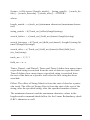
The following two examples show how to use the data editing commands. Type each command slowly and completely. Then try a driver’s
license or credit card to verify the result.
Example One:
/e/d/fn<CR>
/e/d/fe 11<CR>
/e/d/fr ITS ; \cr<CR>
/e/d/ft 7a0a1b0c1c0c2d0b0c 7b1c0c1e0c1f0c3d3e0c2f0c<CR>
First line “/e/d/fn<CR>” is to clear all previous setting.
Second line “/e/d/fe 11<CR> is to enable the data editing and allowing
send out original data if it does not match the formula.
Third line “/e/d/fr ITS ; \cr<CR>” is to create three added fields.
“Field a” is “ITS”, “Field b” is “;” and “field c” is <CR>.
19
The last line will generate two formulas, one for Credit Card and the
other for DMV card.
Example Two:
/e/d/fn<CR>
/e/d/fe 10<CR>
/e/d/fr \cr<CR>
/e/d/fs c1a0101? d2b0101=0101=<CR>
/e/d/ft 7d1a0a2b0a<CR>
The first line “/e/d/fn<CR>” is to clear all previous settings.
The second line “/e/d/fe 10<CR>” is to enable the data editing and will
not send out original data if it does not match the formula.
The third line “/e/d/fr \cr<CR> is to create an added field, “field a” <CR>.
The fourth line “/e/d/fs c1a0101? d2b0101=0101=<CR>” will try to
generate two flexible fields as described in page19.
The last line will generate a single formula for “custom format”. Any
card data can be treated as a custom format as long as it does
not match any other format specified by other formula. Try your
DMV card will see the result, any card does not match the
formula will not be send.
The Flexible Field is:
7d1a0a2b0a
7d: Flexible format
1a: Track1 data before end sentinel (?)
0a: Added field a (<CR>)
2b: Track2 data between the first equal sign and the second equal sign
0a: Added field a (<CR>)
Data will be output as following(if matches the format) or nothing(if
does not match the format):
<Track1 data before end sentinel>
<Track2 date between the first “=” and the second “=”>
20
Section 5
OPERATION
The MiniMag reader is easy to operate. Just follow these simple steps:
1. Make sure the reader is properly cabled and is receiving sufficient
power. (See Section 5, Troubleshooting, if there is a cabling or power
problem.)
2. To read a card, slide the card, in either direction, through the reader
slot, with the magnetic stripe facing the magnetic head (LED side).
3. While swiping the card through the reader, the LED will go off.
4. Once the entire magnetic stripe has been read, the LED indicator
will light up as green to signal a “good read.” If a good read is not
obtained, the LED indicator will light up as red.
5. A beep will also sound to indicate a good read on each track. If all
three tracks have been read successfully, the reader will beep three
times.
21
Section 6
TROUBLESHOOTING
The MiniMag reader is easy to install and use. Most problems encountered can be attributed to:
• Incorrect Interface Cabling
• Incorrect Configuration Setup
• Bad Magnetic Stripe Quality
General Procedures
The troubleshooting process can be simplified by following these
simple diagnostic procedures.
1. The unit should emit one long beep when power is first applied. If it
does not, then the unit is not receiving power.
2. Once it has been confirmed that the unit is correctly powered, try
swiping a credit card. The LED will go off while decoding, then light
green to indicate a “good read,” or red to indicate a “bad read.”
3. Once the unit has indicated a “good read,” then proceed to check the
interface cabling connections.
22
Keyboard Interface Problems
Installation of the reader is generally trouble free, but there are some
things to watch for if you are experiencing problems.
Do you have the proper cable?
Most modern computers and terminals use a PC/XT/AT-compatible
keyboard. However, the cable connecting it to the keyboard port may
have variations in either the signal pins or the connector itself. Make
sure that you have the proper cable for the computer/terminal with
which you are interfacing.
Does the keyboard work?
Since the data from the keyboard must pass through the reader, the
cabling connections are correct if the keyboard is operational.
Can the host computer accept the data fast enough?
Some computers and terminals are expecting the data rate from the
keyboard port to come in at a keystroke rate, and might not be able to
accept it as fast as the reader is transmitting. Try adjusting the intercharacter delay to simulate the effects of keystroke delays.
23
Appendix A. Default Settings Table
The MiniMag reader is shipped from the factory with the following
default settings already programmed:
Magnetic Track Basic Data Format
Track 1: <SS1><T1 Data><ES><ENTER>*
Track 2: <SS2><T2 Data><ES><ENTER>*
Track 3: <SS3><T3 Data><ES><Enter>*
where: SS1(start sentinel track 1) = %
SS2(start sentinel track 2) = ;
SS3(start sentinel track 3) = ; for ISO, ! for CDL, %
for AAMVA
ES(end sentinel all tracks) = ?
Keyboard Wedge Communication Default Settings
Terminal type: IBM PC/AT
Intercharacter delay: 2 ms
Language: US English
Start or End Sentinel: Characters in encoding format which come
before the first data character (start) and after the last data character
(end), indicating the beginning and end, respectively, of data.
Track Separator: A designated character which separates data tracks.
Terminator: A designated character which comes at the end of the last
track of data, to separate card reads.
LRC: Check character, following end sentinel.
CDL: Old California Drivers License format.
*Note: The <ENTER> commands shown above for tracks 1 & 2 and 2 & 3
denote the default character for this position, the Track Separator position.
The <Enter> command shown for track 3 denotes the default character for
this position, the Terminator position.
24
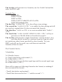
Appendix B. Function Code Table
Character
Keystroke
Character
Keystroke
F1
\f1
End
\end
F2
\f2
Right
\right
F3
\f3
Left
\left
F4
\f4
Up
\up
F5
\f5
Down
\down
F6
\f6
PgUp
\pgup
F7
\f7
PgDn
\pgdn
F8
\f8
Tab
\tab
F9
\f9
Back Tab
\btab
F10
\fa
Esc
\esc
F11
\fb
Enter
\enter
F12
\fc
CR
\cr
Ins
\ins
LF
\lf
Home
\home
Backspace
\bs
To input the “\” character, type it twice. For example, typing ab\\cd in a
preamble string will result in ab\cd as the preamble.
Note: The Function key is not supported on the Apple Macintosh.
25
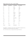
Appendix C: Non-printable ASCII Characters
Character
Keystroke
NULL
SOH
STX
ETX
EOT
ENQ
ACK
BEL
BS
HT
LF
VT
FF
CR
SO
SI
DLE
DC1
DC2
DC3
DC4
NAK
SYN
ETB
CAN
EM
SUB
ESC
FS
GS
RS
US
\nul
\soh
\stx
\etx
\eot
\enq
\ack
\bel
\bs
\ht
\lf
\vt
\ff
\cr
\so
\si
\dle
\dc1
\dc2
\dc3
\dc4
\nak
\syn
\etb
\can
\em
\sub
\esc
\fs
\gs
\rs
\us
26
Appendix D: Magnetic Stripe Standard Data
Formats
International Standards Organization (ISO) Credit Card Format
Track 1
Field ID
Character
Contents
Length
a
b
c
d
e
f
g
h
i
j
Start Sentinel
Format Code “B”
Account Number
Separator “^”
Cardholder Name
Separator “^”
Expiration date
Optional Discretionary data
End Sentinel
Linear Redundancy Check
(LRC) Character
1
1
13 or 16
1
variable
1
4
variable
1
Start Sentinel
Account Number
Separator “=”
Expiration date “YYMM”
Optional discretionary data
End Sentinel
Linear Redundancy Check
(LRC) Character
1
13 or 16
1
4
variable
1
Track 2
a
b
c
d
e
f
g
27
1
1
California Driver’s License Format
Track 1
a
b
c
d
e
f
g
h
Start Sentinel
Format Code Type:
C = Commercial
S = Salesperson
D = Driver
I = Identification
R = Senior Citizen
Name Line 1
Name Line 2
Address Line 1
City
End Sentinel
Linear Redundancy Check
(LRC) Character
1
1
29
29
29
13
1
1
Track 2
a
b
c
d
e
f
g
h
Start Sentinel
Identification Number
ANSI User ID
DL/ID Alpha Translated
7 position DL/ID number
Check Digit
Field Separator “=”
Expiration Date
Field Separator “=”
Discretionary Data,
8 position birthdate
End Sentinel
Linear Redundancy Check
(LRC) Character
28
1
6
2
7
1
1
4
1
8
1
1
Track 3
a
b
c
d
e
f
g
h
i
j
k
l
m
n
o
p
q
r
s
t
Start Sentinel
Class
Endorsements
State Code
Zip Code
Sex
Hair
Eyes
Height
Weight
Restrictions
Issue Date
Office
Employee ID
LRE ID
Fee Due Year
Address Line 2
Reserved Space
End Sentinel
Linear Redundancy Check
(LRC) Character
1
4
4
2
9
1
3
3
3
3
10
8
3
2
2
4
29
10
1
1
AAMVA Driver’s License Format
Track 1
a
b
c
d
e
f
g
Start Sentinel
State or Province
City
Name
Address
End Sentinel
Linear Redundancy Check
(LRC) Character
29
1
2
13
35
29
1
1
Track 2
a
b
c
d
e
f
g
h
i
Track 3
a
b
c
d
e
f
g
h
i
j
k
l
m
n
o
p
q
r
Start Sentinel
ANSI User Code
ANSI User ID
Jurisdiction ID/DL
Expiration date
Birthdate
Remainder of Jurisdiction
ID/DL
End Sentinel
Linear Redundancy Check
(LRC) Character
1
1
5
14
4
8
Start Sentinel
Template Version #
Security Version #
Postal Code
Class
Restrictions
Endorsements
Sex
Height
Weight
Hair Color
Eye Color
ID #
Reserved Space
Error Correction
Security
End Sentinel
Linear Redundancy Check
(LRC) Character
1
1
1
11
2
10
4
1
3
3
3
3
10
16
6
5
1
30
5
1
1
1
Appendix E: USB/Keyboard Interface
The MiniMag reader is available with a cable that terminates in a
Universal Serial Bus (USB) connector. Most new computers have
multiple USB ports into which a wide variety of peripherals can be
installed.
Since USB devices are designed to be “plug and play,” the computer
will search for a Human Interface Device (HID) driver when the
MiniMag is first connected. If one cannot be found, the computer will
prompt you to make a selection. The Windows CD may be needed to
complete the installation.
The MiniMag reader is shipped from the factory with default
configuration settings already programmed. (See Appendix A: Default
Settings Table for details.) These settings are satisfactory for most
applications. In order to change these settings, it is necessary to run the
ID TECH USB Reader Setup Utility. The Reader Setup Utility allows
you to enter commands through the keyboard, just as if the reader were
physically connected between the keyboard and the computer.
To install the ID TECH Reader Setup, just follow these steps:
1. Insert the diskette into Drive A.
2. Click START.
3. Click RUN.
4. Enter A: SETUP.
5. Click OK.
6. Follow the instructions on the screen.
7. Close the ID TECH Setup Utility when all files have been copied.
8. Click FINISH.
31
To use the ID TECH Reader Setup, follow these steps:
1. Go to the PROGRAM menu.
2. Select ID TECH USB Reader Setup.
3. When the screen appears, enter a command in the window labeled
INPUT SETUP STRING , just as you would with a standard keyboard
wedge interface. You do not have to use Notepad.
4. Click SEND.
5. If the command is accepted, the MiniMag will beep once. If the
command is rejected, the MiniMag will beep twice.
6. You can clear the INPUT SETUP STRING window by clicking on
CLEAR INPUT.
7. The HISTORY window displays previous commands. To re-use
a command, highlight the command in HISTORY and right click
to select COPY. Position the cursor in the INPUT SETUP STRING
window and right click to select PASTE.
8. To end your session, click on EXIT. This will clear all data in the
HISTORY window.
Note: When using the MiniMag in conjunction with a laptop computer or
other battery-operated host, power to the USB port may be shut down when
the battery runs low. If this happens, charge (or replace) the battery and then
reboot to continue.
Note: The Function key is not supported on the Apple Macintosh.
32
ID TECH
10721 Walker Street
Cypress, California 90630-4720
(714) 761-6368
www.id-tech.net
80030501-001
Rev. A R09/05
#414