1
MINIMAG
RS-232
User’s Manual
TM
Table of Contents
Agency Approved
Specifications for subpart B of part 15 of FCC rule for a Class A
computing device.
Limited Warranty
ID TECH warrants this product to be in good working order for a
period of one year from the date of purchase. If this product is not in
good working order as warranted above, or should this product fail to
be in good working order at any time during the warranty period,
repair or replacement shall be provided by ID TECH.
This warranty does not cover incidental or consequential damages
incurred by consumer misuse, or modification of said product. For
limited warranty service during the warranty period, please contact
ID TECH to obtain an RMA number and instructions for returning
the product.
©2000 ID TECH, Inc. The information contained herein is provided
to the user as a convenience. While every effort has been made to
ensure accuracy, ID TECH is not responsible for damages that
might occur because of errors or omissions, including any loss of
profit or other commercial damage. The specifications described
herein were current at the time of publication, but are subject to
change at any time without prior notice.
MiniMag, ID TECH, and Value through Innovation are trademarks
of ID TECH, Inc. PC, PC/XT, PC/AT, PS/1, and PS/2 are trademarks of International Business Machines.
Section 1. Introduction
Description
Section 2. Installation
Host Connections
Section 3. Configuration
Setup Commands Structure
Communication Protocol
Communication Timing
Default Settings
General Selections
Message Formatting Selections
Magnetic Track Selections
Communication Parameter
Selections
Output Format Selection
Section 4. Data Editing
Functions
Fields
Formulas
Data Editing Setup Commands
Section 5. Operation
Operating Procedure
Section 6. Troubleshooting
General Procedures
Appendix A. Default Settings
Default Settings
Appendix B. Function Codes
Function Code Table
Appendix C. Non-Printable ASCII Characters
ASCII Characters Table
Appendix D. Magnetic Stripe Standard Data Formats
ISO Credit Card
California Driver’s License
AAMVA Driver’s License
Appendix E. MiniMag Configuration Utility
Operation
Commands
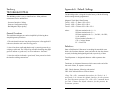
Appendix F. Pin Out Information
DB-9 Female Connector
1
2
3
4
5
6
6
9
10
12
14
16
17
18
19
24
25
26
28
29
30
31
33
35
36
40
Section 1
INTRODUCTION
Section 2
INSTALLATION
Description
Host Connections
The MiniMag™ compact magnetic stripe reader can read 1, 2, or 3
tracks of magnetic stripe information. In addition, it has full data
editing capabilities. The data can be formatted with preamble/
postamble and terminator characters to match the format expected
by the host.
The MiniMag is connected to the host computer’s RS-232 communications port. The cable has a DB-9 connector at one end, and is
connected to the reader at the other end. (An adapter can be used to
connect to a DB-25 RS-232 port.)
The MiniMag can be connected to a host computer via an RS-232
input port. When the reader is connected as an RS-232 device, a
separate power module must be used.
Data is transmitted to the host in an ASCII data format. The
reader’s output can be formatted with terminating characters and
special preamble and/or postamble character strings to match the
data format expected by the terminal.
The terminal must be configured to accept the data and to perform
the appropriate processing. Care must be taken to ensure that the
RS-232 parameters (baud rate, data bits, Start/Stop characters,
parity, and handshaking method) match those expected by the
terminal. Just transmitting the data to the serial port does not necessarily mean it will appear on the screen as if it were entered manually.
Use the MiniMag Configuration Utility Application to program the
reader, and a communication program (such as Procomm or
Hyperterminal) to display the data.
There is insufficient power available on a standard RS-232 serial
port to power the MiniMag, so an external wall-mounted power
module must be used. Connect the power cable from this unit to the
power receptacle located on the DB-9 connector. Care must be
taken to ensure the power module outputs +5 volts.
1
2
Section 3
CONFIGURATION
The MiniMag reader must be appropriately configured to your
application. Configuration settings enable the reader to work with the
host system.
<FuncID> is a one byte Function ID identifies the particular function
or settings affected.
<Len> is a one byte length count for the following data
block<FuncData>
<FuncData> is the data block for the function.
These settings are programmed into the reader using the MiniMag
Configuration Utility Program, or by sending Setup Commands from
the host application to the reader. Once programmed, these configuration settings are stored in the reader’s non-volatile memory (so
they will not be affected by the cycling of power).
<ETX> = 03h
For instructions on how to use the MiniMag configuration Utility, see
Appendix E.
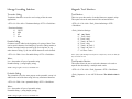
Communication Protocol
Note: If you want to send setup commands to the MiniMag, you
must make sure the communication parameters are always 9600,
None, 8, 1. Before you make any settings, or try to get data to
the host, check the connection cable, port, power and communication parameters.
The overall Modulo 2 (Exclusive OR) sum (from <STX> to
<CheckSum>) should be zero.
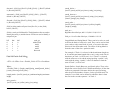
Sending Command
Host
MiniMag
Send Command
ACK if OK
or
NAK if Error
Setup Commands Structure
Sending command:
<STX><S>[<FuncID><Len><FuncData>…]<ETX><CheckSum>
Receiving command:
<STX><R>[<FuncID><Len><FuncData>…]<ETX><CheckSum>
Where:
<STX> = 02h
3
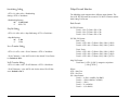
Receiving Command
Host
MiniMag
Receiving Command
ACK and <Response> if OK
NAK if Error
4
Communication Timing
Default Settings
The MiniMag takes time to process a command. During that processing time, it will not respond to a new command.
The MiniMag reader is shipped from the factory with the default
settings already programmed. In the following sections, the default
settings are shown in boldface.
Although the typical delay for the reader to respond to a command is
0.1ms, the maximum delay for the reader to respond can be as much
as 5ms. Caution must therefore be taken to maintain a minimum
delay between two commands.
Use the following formula to calculate the delay:
80ms + 10(number of bytes in <FuncData> of the first command)ms
NOTE: The maximum delay allowed between two characters in a command is 2ms.
For a table of default settings, see Appendix A.
General Selections
This group of configuration settings define the basic operating
parameters of the scanner.
Beep Volume
The beep volume can be adjusted to two different levels, or turned
off entirely.
< STX ><S><11h><01h><Beep Volume
Settings><ETX><CheckSum>
Beep Volume Settings:
‘0’ for beep volume off
‘1’ for beep volume low
‘2’ for beep volume high
Change To Default Settings
<STX><S><18h><ETX><CheckSum>
This command does not have any <FuncData>. It returns all settings
for all groups to their default values. Data Editing will be turned off,
and the formulas will be retained.
5
6
MSR Reading Settings
Review Settings
Turn the MiniMag on or off. If the reader is disabled, no data will be
sent out to the host.
<STX><R><1Fh><ETX><CheckSum>
<STX><S><1Ah><01h><MSR Reading
Settings><ETX><CheckSum>
MSR Reading Settings:
“0”
“1”
MSR Reading Disabled
MSR Reading Enabled
This command does not have any <FuncData>. It activates the
review settings command. MiniMag sends back an <ACK> and
<Response>.
<Response> format:
The current setting data block is a collection of many functionsetting blocks <FuncSETBLOCK> as follows:
<STX><FuncSETBLOCK1>…<FuncSETBLOCKn><ETX><CheckSum>
Decoding Method Settings
The MiniMag can support three kinds of decoded directions.
Each function-setting block <FuncSETBLOCK> has the following
format:
<FuncID><Len><FuncData>
<STX><S><1Dh><01h><Decoding Method
Settings><ETX><CheckSum>
Where:
Decoding Method Settings:
<FuncID> is one byte identifying the setting(s) for the function.
“0”
“1”
“2”
“3”
Raw Data Decoding in Both Directions
Decoding in Both Directions
Moving Stripe Along Head in Direction of Encoding
Moving Stripe Along Head Against Direction of
Encoding
With the bi-directional method, the user can swipe the card in either
direction and still read the data encoded on the magnetic stripe.
Otherwise, the card can only be swiped in one specified direction to
read the card.
7
<Len> is a one byte length count for the following function-setting
block <FuncData>
<FuncData> is the current setting for this function. It has the same
format as in the sending command for this function.
<FuncSETBLOCK> are in the order of their Function ID<FuncID>
8
Message Formatting Selections
Magnetic Track Selections
Terminator Setting
Track Selection
Terminator characters are used to end a string of data in some
applications.
There are up to three tracks of encoded data on a magnetic stripe.
This option selects the tracks that will be read and decoded.
<STX><S><21h><01h><Terminator Settings><ETX><CheckSum>
<STX><S><13h><01h><Track_Selection Settings><ETX>
<CheckSum>
<Terminator Settings>
‘0’ CR/LF
‘1’ CR
‘2’ LF
‘3’ None
Preamble Setting
Characters can be added to the beginning of a string of data. These
can be special characters for identifying a specific reading station, to
format a message header expected by the receiving host, or any
other character string. Up to nine ASCII characters can be defined.
<Track_Selection Settings>
“0”
“1”
“2”
“3”
“4”
“5”
“6”
“7”
Any Track
Track 1 Only
Track 2 Only
Track 1 & Track 2
Track 3 Only
Track 1 & Track 3
Track 2 & Track 3
All Three Tracks
<STX><S><D2h><Len><Pre-amble String><ETX><CheckSum>
Note: If any of the multiple tracks fails to read for any reason, no data for
any track will be sent.
Where:
Len = the number of bytes of preamble string
Preamble String = {string length}{string}
Track Separator Selection
NOTE: String length is one byte, maximum nine.
Postamble Setting
The postamble serves the same purpose as the preamble, except it is
added to the end of the data string, after any terminator characters.
This option allows the user to select the character to be used to
separate data decoded by a multiple-track reader.
<STX><S><17h><01h><Track_Separator><ETX><CheckSum>
<Track_Separator> is one ASCII Character. The default value is
CR.
<STX><S><D3h><Len><postamble String><ETX><CheckSum>
Where:
Len = the number of bytes of postamble string
Postamble String = {string length}{string}
NOTE: String length is one byte, maximum nine.
9
10
Start/End Sentinel And Track 2 Account Number Only
Communication Parameter Selections
The MiniMag can be set to either send, or not send, the Start/End
sentinel, and to send either the Track 2 account number only, or all
the encoded data on Track 2. (The Track 2 account number setting
doesn’t affect the output of Track 1 and Track 3.)
Baud Rate Setting
<STX><S><19h><01h><SendOption><ETX><CheckSum>
<Send Option>
“0”
Not send start/end sentinel and send all data on Track 2
“1”
Send start/end sentinel and send all data on Track 2
“2”
Not send start/end sentinel and send account number on
Track 2
“3”
Send start/end sentinel and send account number on Track 2
<STX><S><41h><01h>< Baud Rate Setting><ETX><CheckSum>
<Baud Rate Setting>:
“3”
2400 bps
“4”
4800 bps
“5”
9600 bps
“6”
19200 bps
Parity Setting
<STX><S><43h><01h>< Parity Setting><ETX><CheckSum>
<Parity Setting>:
“0”
None
“1”
Even
“2”
Odd
“3”
Mark
“4”
Space
Data Bit Setting
<STX><S><42h><01h>< Data-Bit Setting><ETX><CheckSum>
<Data-Bit Setting>:
“0”
8 Bits
“1”
7 Bits
11
12
Handshaking Setting
Output Format Selection
<STX><S><44h><01h>< Handshaking
Setting><ETX><CheckSum>
The MiniMag reader supports three different output formats. The
first is ID TECH Format, the second is UIC RS-232 Format, and the
third is Mag-Tek Format.
<Handshaking Setting>:
“0”
X-On/X-Off
“1”
RTS/CTS
Stop Bit Setting
<STX><S><45h><01h>< Stop-Bit Setting><ETX><CheckSum>
<Stop-Bit Setting>:
“0”
1 Bit
“1”
2 Bits
X-on Character Setting
<STX><S><47h><01h>< X-On Character><ETX><CheckSum>
<X-On Character> is the ASCII code for the desired X-On Character. Default is DC1.
X-off Character Setting
<STX><S><48h><01h>< X-Off Character><ETX><CheckSum>
<X-Off Character> is the ASCII code for the desired X-Off Character. Default is DC3.
13
Data Formats
ID TECH Format:
Track1: <SS><T1 Data><ES><CR>
Track2: <SS><T2 Data><ES><CR>
Track3: <SS><T3 Data><ES><CR>
UIC RS-232 Format:
Dual Track:
Track1: <STX><SS><T1 Data><ES>[<LRC>]<DLE>
Track2: <STX><SS><T2 Data><ES>[<LRC>]<DLE>
Triple Track:
Track1: <STX><SS><T1 Data><ES>[<LRC>]<DLE>
Track2: <STX><SS><T2 Data><ES>[<LRC>]<DLE>
Track3: <STX><SS><T3 Data><ES>[<LRC>]<ETX>
Mag-Tek Format:
Track Data: [<STX>][<ESC>]<magnetic stripe data>
[<CR>][<ETX>]
Where:
STX = Start Text
ETX = End Text
SS = Start Sentinel
Track1 = % (ISO, AAMVA,CA-DMV)
Track2 = ; (ISO,AAMVA,CA-DMV)
Track3 = ; (ISO)
Track3 = % (AAMVA)
Track3 = ! (CA-DMV)
14
Section 4
DATA EDITING
ES = End Sentinel
All Tracks = ? (ISO, AAMVA, CA-DMV)
LRC = Longitudinal Redundancy Character
DLE = Data Link Escape
Output Format Settings
<STX><15h><01h><Output Format Setting><ETX><CheckSum>
Output Format Setting:
“0”
ID TECH Format
“1”
UIC Format
“2”
Mag-Tek Format
The MiniMag has a data editing feature incorporated into its firmware. This feature allows the data read from the magnetic stripe to
be sent to the host in the exact format expected by the host software, eliminating the need for modifications to the application
software.
Format Option Setting
The data (that is, the input record from the magnetic stripe) can be
divided up into a number of separate fields, according to established
standards (such as ISO, ANSI, AAMVA, and CDL). The data in
each of these fields can then be edited, and new fields can be
defined using the Data Edit commands.
Format Option Setting:
The edited data fields are then transmitted to the host in any order
desired, regardless of their position on the original magnetic stripe.
<STX><16h><01h>< Format Option Setting><ETX><CheckSum>
BIT
0
1
2
3
4
5
6
SETTING
BIT SET TO 1 BIT SET TO 0
Sending LRC in UIC Format
Buffer Mode in Mag-Tek Format
Command Mode in Mag-Tek Format
Sending STX in Mag-Tek Format
Sending ESC in Mag-Tek Format
Sending CR in Mag-Tek Format
Sending ETX in Mag-Tek Format
No
Yes
+/No
No
No
No
Yes
No
I/R
Yes
Yes
Yes
Yes
Functions
The following editing functions can be performed:
Rearrange the Data: The fields within a track, created by established
standards, can be transmitted to the host in any order desired,
regardless of the order in which they occurred in the card track.
Insert Character Strings into the Output Data Record: Character
strings can be defined and inserted at any place in the data output
record.
Duplicate Fields: Fields within a track can be transmitted to the host
as many times as desired, and in any order.
Select Output Fields: Fields within a track can be selected for output
or not selected for output.
15
16
Fields
Formulas
By separating the input data record into smaller blocks (called
“fields”), each block can be edited individually. Additional fields can
also be added to the record, allowing specific functions, such as
carriage returns or keyboard function keys, to be inserted at any
point. (The field standards for ISO Credit Cards, California driver’s
licenses, and AAMVA driver’s licenses are listed in Appendix D.)
The set of instructions programmed into the MiniMag to edit data is
referred to as the data editing “formula.” More than one formula (to
a maximum of four) can be resident in the reader at one time. If
more than one formula resides in memory, the reader will apply the
first formula to the input data. If the data format matches the format
(credit card, driver’s license, etc.) of the first formula, then it will
apply the data editing functions and output the reformatted data to
the host.
By separating the input data record into smaller blocks (fields), each
block can then be treated individually. Additional fields can also be
added to the record in any position, allowing specific functions, such
as carriage returns. Fields are identified by a one-character ID
starting with the character “a,” up to and including “z,” in the order
they were created, allowing as many as 26 fields to be defined.
These fields are then sent to the host in the order which the user
specifies. For example, if the input data record is in the Credit Card
Format for Track 2:
;1234567890123456=9912xxxxxxx?c
Field ID |a|
b
|c| d |
e |f|g|
and your application software is looking for the data to be in the
following format:
If the data does not match the criteria spelled out in the first formula,
then the criteria of the second formula is applied. This process
continues for each of the successive formulas until a match is found.
If no matches are found to any of the formulas programmed into the
reader, then either nothing will be transmitted to the host, or the
unedited data record will be transmitted, according to the data editing
matched flag, whether it is set or not.
The MiniMag supports four kinds of formulas for credit card,
California driver’s license, AAMVA formats, as well as a customized format. The user can define all four, or only one at a time.
However, the MiniMag can only keep one credit card, one California
driver’s license, one AAMVA, and one customized format at a time.
9912<CR>
1234567890123456<CR>
then we must divide the data record into fields, select only those
fields desired, reverse the order in which they are sent to the host,
and create a new field <CR> and insert it after each field.
We do this by using the defined fields and adding a new field:
Field b = 1234567890123456
Field d = 9912
Field h = <CR>
and sending {Field d}{Field h}{Field b}{Field h}
17
18
Data Editing Setup Commands
The following commands are used to set the operating parameters of
the Data Editing feature. These commands are designed for maximum flexibility, but some of the details can be complicated. We
therefore suggest that the MiniMag Configuration Utility be used to
set these commands.
Added Field
An output field is created containing the character string. Up to six
fields can be defined. The maximum number of characters for each
field is six.
Search Method
In working with a user-defined format that is not credit card, CA
DMV, or AAMVA, the MiniMag will support any combination of the
following five search methods:
Length Match: For a particular track, indicate the minimum and
maximum number of characters acceptable for the data editing
formula.
String Match: For a particular track, indicate a specific string of
characters, as well as the character position at which that string
must begin, in order to be acceptable to the data editing formula.
Search Before: For a particular track, the MiniMag will create a
data field which contains all characters that come before the specified occurrence of a given character sequence. (For example, the
second occurrence of the character sequence ABC.)
Search Between: For a particular track, the MiniMag will create a
data field which contains all characters that come between the
specified occurrence of one sequence of characters and another.
Search After: For a particular track, the MiniMag will create a data
field that contains the specified number of characters that come
after the specified occurrence of a given character sequence. (An
offset of a given number of character positions can also be indicated.)
19
Send Sequence
Sends out the field in a user-defined order.
Data Edit Setting
<STX><S><1Bh><01h>< Data Edit Setting><ETX><CheckSum>
<Data Edit Setting>:
“0”
Disable data edit.
“1”
Enable data edit, do not send data that does not
match the data edit formulas.
“3”
Enable data edit, send data that does not match the
data edit formulas “as is.”
Data Edit Added Field Setting
<STX><S><FAh><Len>< Added Field><ETX><CheckSum>
Where:
<Added Field> is [string1] ... [stringn], n <= 6
stringn = {string_len}{string}, string_len <= 6
{string} is always six bytes. If a string is less than six characters
long, you must pad the end with hex 0 (ASCII: Null).
Data Edit Send Command Setting
<STX><S><FCh><Len>< Send_Command><ETX><CheckSum>
Where:
<Send_Command> is [ccsmd] [dmvsmd][aamvasmd] [flexsmd]
ccsmd = {field_len}{Hex E0}{field}[{field}...,] {Hex FF} default is
{Hex 00}{Hex FF}
20
dmvsmd = {field_len}{Hex E1}{field}[{field}...,]{Hex FF} default
is {Hex 00}{Hex FF}
search_before =
{hex F2}{track_no|field_no}{times}{string_len}{string}
aamvasmd = {field_len}{Hex E2}{field}[{field}...,]{Hex FF}
default is {Hex 00}{Hex FF}
search_between =
{hex F3}{track_no|field_no}{times1}{string1_len}{string1}
{times2}{string2_len}{string2}
flexsmd = {field_len}{Hex E3}{field}[{field}...,]{Hex FF} default
is {Hex 00}{Hex FF}
field_len is the number of bytes from {Hex Ex} to the {field}
before {Hex FF}.
field is a one byte field identifier. The highest three bits are used to
identify the track_no, and the lowest five bits are used to identify a
unique field_no.
bit7
0
0
0
0
1
bit6
0
0
1
1
x
bit5
0
1
0
1
x
track_no
Added Field
track1
track2
track3
Reserved
Data Edit Flexible Field Setting
<STX><S><FBh><Len>< Flexible_Field><ETX><CheckSum>
Where:
<Flexible_Field> is [length_match][string_match][search_before]
[search_between][search_after]…
length_match = {hex F0}{track_no}{minimum length}{maximum
length}
search_after =
{hex F4}{track_no|field_no}{times1}{offset}{length2}
{length1}{string1}
track_no =
High three bits of the byte, 001*****|010*****|011*****
field_no = Low five bits of the byte, ***00000~***11111
Length Match and String Match: These restrictive rules are used
to define the kinds of cards to be read. They can be used to limit
your reader to only some kinds of cards, or to restrict the transmission of data from other cards. The offset of String Match is
from the start of data for a particular track.
For example, if Track 1 is selected, with the minimum length set
at 10, and the maximum length also set at 10, only cards with 10
characters on Track 1 will be read. Or, if Track 3 is selected,
with the offset set at 10, and the string equaling “symbol,” only
cards with the string “symbol,” offset 10 characters from the
start of Track 3, will be read.
Search Before, Search Between, and Search After: These rules
help define a new flexible field. With Search Before, all the data
in the new generated field comes before the specified string,
after the specified number of times, for the specified track. For
example, a new field can be defined in which the data is from
the start to the second separator ^ in Track 1.
string_match =
{hex F1}{track_no}{offset}{string_len}{string}
21
22
With Search Between, all the data in the new generated field
comes between the two specified strings for the specified track.
For example, a new field can be defined in which the data comes
between the first searched separator ^ and the first searched $.
With Search After, all the data in the new generated field starts
from the specified offset, after the specified strings, after the
specified number of times, for the specified track. For example, a
new field can be defined in which the data starts after a 10 character offset after the first searched separator ^.
Times, Times1, and Times2: Times and Times1 define how many
times a specified string is searched from the start of data on a
specific track. Times2 defines how many times a specified string is
searched from the rest of the data on a specific track after the first
string has been searched.
Track No. and Field No.: The Track Number (3 bits) and the Field
Number (5 bits) are always in one byte.
NOTE: The field definitions for common magnetic card formats
are listed in Appendix D.
23
Section 5
OPERATION
The MiniMag reader is easy to operate. Just follow these simple
steps:
1. Make sure the reader is properly cabled and is receiving sufficient
power. (See Section 5, Troubleshooting, if there is a cabling or power
problem.)
2. To read a card, slide the card, in either direction, through the
reader slot, with the magnetic stripe facing the magnetic head (LED
side).
3. While swiping the card through the reader, the LED will go off.
4. Once the entire magnetic stripe has been read, the LED indicator
will light up as green to signal a “good read.” If a good read is not
obtained, the LED indicator will light up as red.
5. A beep will also sound to indicate a good read on each track. If all
three tracks have been read successfully, the reader will beep three
times.
24
Section 6
TROUBLESHOOTING
The MiniMag reader is easy to install and use. Most problems
encountered can be attributed to:
· Incorrect Interface Cabling
· Incorrect Configuration Setup
· Bad Magnetic Stripe Quality
Appendix A. Default Settings
The MiniMag reader is shipped from the factory with the following
default settings already programmed:
Magnetic Track Basic Data Format
Track 1: <SS1><T1 Data><ES><CR>*
Track 2: <SS2><T2 Data><ES><CR>*
Track 3: <SS3><T3 Data><ES><CR><LF>*
where:
General Procedures
The troubleshooting process can be simplified by following these
simple diagnostic procedures.
1. The unit should emit one long beep when power is first applied. If
it does not, then the unit is not receiving power.
2. Once it has been confirmed that the unit is correctly powered, try
swiping a credit card. The LED will go off while decoding, then light
green to indicate a “good read,” or red to indicate a “bad read.”
3. Once the unit has indicated a “good read,” then proceed to check
the interface cabling connections.
SS1(start sentinel track 1) = %
SS2(start sentinel track 2) = ;
SS3(start sentinel track 3) = ; for ISO, ! for CDL,
% for AAMVA
ES(end sentinel all tracks) = ?
CR = Carriage Return
LF = Line Feed
Definitions
Start or End Sentinel: Characters in encoding format which come
before the first data character (start) and after the last data character (end), indicating the beginning and end, respectively, of data.
Track Separator: A designated character which separates data
tracks.
Terminator: A designated character which comes at the end of the
last track of data, to separate card reads.
LRC: Check character, following end sentinel.
CDL: Old California Drivers License format.
*Note: The <CR> commands shown above for Tracks 1 & 2
and Tracks 2 & 3 denote the default character for this position,
the Track Separator position. The <CR><LF> command shown
for Track 3 denotes the default character for this position, the
Terminator position.
25
26
Default Setting Table
27
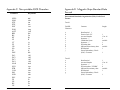
Appendix B. Function Code Table
Setting
Default
Character
Keystroke
Character
Keystroke
Beep Volume
High
F1
\f1
End
\end
MSR Reading
Enable
F2
\f2
Right
\right
Decoding Method
Both Swiping Direction
F3
\f3
Left
\left
Terminator Settings
CR
F4
\f4
Up
\up
Preamble Settings
None
F5
\f5
Down
\down
Postamble Settings
None
Track_Selected Settings
Any Track
F6
\f6
PgUp
\pgup
Track_Selected Settings
CR
F7
\f7
PgDn
\pgdn
Sentinel and T2 Account No.
Send Sentinels and all T2 data
F8
\f8
Tab
\tab
Baud Rate Setting
9600 bps
F9
\f9
Back Tab
\btab
Parity Setting
None
F10
\f10
Esc
\esc
Data-Bit Setting
8
F11
\f11
Enter
\enter
Handshaking Setting
X-On/X-off
F12
\f12
CR
\cr
Stop-Bit Setting
1
Ins
\ins
LF
\lf
X-On Character Setting
DC1 (Hex 11)
Home
\home
Backspace
\bs
X-Off Character Setting
DC3 (Hex 13)
Data Edit Setting
Disabled
To input the “\” character, type it twice. For example, typing ab\\cd
in a preamble string will result in ab\cd as the preamble.
28
Appendix C. Non-printable ASCII Characters
Character
NULL
SOH
STX
ETX
EOT
ENQ
ACK
BEL
BS
HT
LF
VT
FF
CR
SO
SI
DLE
DC1
DC2
DC3
DC4
NAK
SYN
ETB
CAN
EM
SUB
ESC
FS
GS
RS
US
29
Keystroke
\nul
\soh
\stx
\etx
\eot
\enq
\ack
\bel
\bs
\ht
\lf
\vt
\ff
\cr
\so
\si
\dle
\dc1
\dc2
\dc3
\dc4
\nak
\syn
\etb
\can
\em
\sub
\esc
\fs
\gs
\rs
\us
Appendix D. Magnetic Stripe Standard Data
Formats
International Standards Organization (ISO) Credit Card
Format
Track 1
Field ID
Character
Contents
a
b
c
d
e
f
g
h
i
j
Start Sentinel 1
Format Code “B”
Account Number
Separator “^”
Cardholder Name
Separator “^”
Expiration date
Optional Discretionary data
End Sentinel
Linear Redundancy Check
(LRC) Character
Track 2
a
b
c
d
e
f
g
Start Sentinel
Account Number
Separator “=”
Expiration date “YYMM”
Optional discretionary data
End Sentinel
Linear Redundancy Check
(LRC) Character
Length
1
13 or 16
1
variable
1
4
variable
1
1
1
13 or 16
1
4
variable
1
1
30
California Driver’s License Format
Track 1
a
b
c
d
e
f
g
h
Start Sentinel
Format Code Type:
C = Commercial
S = Salesperson
D = Driver
I = Identification
R = Senior Citizen
Name Line 1
Name Line 2
Address Line 1
City
End Sentinel
Linear Redundancy Check
(LRC) Character
1
1
29
29
29
13
1
1
Track 2
a
b
c
d
e
f
g
h
31
Start Sentinel
Identification Number
ANSI User ID
DL/ID Alpha Translated2
7 position DL/ID number
Check Digit
Field Separator “=”
Expiration Date
Field Separator “=”
Discretionary Data,
8 position birthdate
End Sentinel
Linear Redundancy Check
(LRC) Character
Track 3
a
b
c
d
e
f
g
h
i
j
k
l
m
n
o
p
q
r
s
t
Start Sentinel
Class
Endorsements
State Code
Zip Code
Sex
Hair
Eyes
Height
Weight
Restrictions
Issue Date
Office
Employee ID
LRE ID
Fee Due Year
Address Line 2
Reserved Space
End Sentinel
Linear Redundancy Check
(LRC) Character
1
4
4
2
9
1
3
3
3
3
10
8
3
2
2
4
29
10
1
1
1
6
7
1
1
4
1
8
1
1
32
AAMVA Driver’s License Format
Track 3
Track 1
a
b
c
d
e
f
g
h
i
j
k
l
m
n
o
p
q
r
a
b
c
d
e
f
g
Start Sentinel
State or Province
City
Name
Address
End Sentinel
Linear Redundancy Check
(LRC) Character
1
2
13
35
29
1
1
Track 2
a
b
c
d
e
f
g
h
i
33
Start Sentinel
1
ANSI User Code
1
ANSI User ID
5
Jurisdiction ID/DL
14
Expiration date
4
Birthdate
8
Remainder of Jurisdiction ID/DL 5
End Sentinel
1
Linear Redundancy Check
(LRC) Character
1
Start Sentinel
Template Version #
Security Version #
Postal Code
Class
Restrictions
Endorsements
Sex
Height
Weight
Hair Color
Eye Color
ID #
Reserved Space
Error Correction
Security
End Sentinel
Linear Redundancy Check
(LRC) Character
1
1
1
11
2
10
4
1
3
3
3
3
10
16
6
5
1
1
34
Appendix E. Minimag Configuration Utility
Commands
Introduction
FILE menu commands
The MiniMag Configuration Utility is a Windows-based program that
makes it easy to configure the reader.
NEW - Creates a new configuration file.
Operation
OPEN - Opens an existing configuration file.
To install the MiniMag Configuration Utility, please follow these
steps:
1. Run Windows 95/98 or Windows NT.
2. Run SETUP from the MiniMag Configuration Utility Disk.
3. Follow the instructions on your screen. The setup program will
prompt you when installation is complete.
To run the MiniMag Configuration Utility, please follow these steps:
1. Open the START menu on the desktop.
2. Point to the PROGRAM menu.
3. Point to MINIMAG CONFIGURATION UTILITY.
4. Click the MINIMAG CONFIG icon.
Use the MiniMag Configuration Utility as follows:
1. To create a file with new settings, open the FILE menu and click
on NEW.
2. To open a file with existing settings, open the FILE menu and
click on OPEN.
3. To see the current settings of a MiniMag reader, open the FILE
menu and click on RECEIVE.
4. To save settings to a disk file, go to the MINIMAG CONFIGURATION PROPERTIES dialog box and click on SAVE CONFIG.
5. To send settings to a MiniMag reader, go to the MINIMAG
CONFIGURATION PROPERTIES dialog box and click on TO
MINIMAG.
35
RECEIVE - Sends the current settings of a MiniMag reader to
the host.
EXIT - Exits the MiniMag Configuration Utility.
VIEW menu commands
TOOLBAR - Shows or hides the toolbar.
STATUS BAR - Shows or hides the status bar.
HELP menu commands
HELP TOPICS - Offers you an index to topics on which you can
get help.
ABOUT - Displays the version number of this application.
INDEX - Use this command to display the opening screen of
HELP. From the opening screen, you can jump to step-by-step
instructions for using the MiniMag Configuration Utility, as well as
access important reference information.
36
CONTEXT HELP - Use the “Context Help” command to obtain
help on any aspect of the MiniMag Configuration Utility. The
HELP topic will be shown for the item you clicked.
MOVE command (in the Control menu)
USING HELP - Use this command to learn how to use HELP.
Note: This command is unavailable if you maximize the window.
FILE OPEN dialog box
The following four options allow you to specify which file to open:
1. FILE NAME - Type or select the file name you want to open.
This box lists files, with the extension you select, in the LIST FILES
OF TYPE box.
2. LIST FILES OF TYPE - Select the type of file you want to open.
3. DRIVES - Select the drive in which the MiniMag Configuration
Utility stores the file that you want to open.
4. DIRECTORIES - Select the directory in which the MiniMag
Configuration Utility stores the file that you want to open.
SIZE command (in the SYSTEM menu)
Use this command to display a four-headed arrow you can use to
size the active window with the arrow keys. After the pointer
changes to the four-headed arrow:
Use this command to display a four-headed arrow you can use to
move the active window or dialog box with the arrow keys.
MINIMIZE command (in the application control menu)
Use this command to reduce the MiniMag Configuration Utility
window to an icon.
MAXIMIZE command (in the system menu)
Use this command to enlarge the active window to fill the available
space.
CLOSE command (in the control menu)
Use this command to close the MiniMag Configuration Utility.
Note: Double-clicking a control menu box is the same as choosing the “Close” command.
RESTORE command (in the control menu)
1. Press one of the DIRECTION keys (left, right, up, or down arrow
key) to move the pointer to the border you want to move.
2. Press a DIRECTION key to move the border.
3. Press ENTER when the window is the size you want.
Use this command to return the active window to the size and
position it had before you chose the “Maximize” or “Minimize”
command.
Note: This command is unavailable if you maximize the window.
SAVE button (MiniMag Configuration Utility properties)
Use this button to save the active configuration file to its current
name and directory. When you save a file for the first time, the
MiniMag Configuration Utility displays the “Save As” dialog box so
you can name your file.
37
38
SEND button (MiniMag Configuration Utility properties)
Use this button to send all current selected settings to the MiniMag
reader.
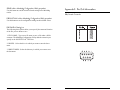
Appendix F. Pin Out Information
DB9 Female Connector
DEFAULT ALL button (MiniMag Configuration Utility properties)
Use this button to set all configuration settings at their default values.
FILE SAVE AS dialog box
The following three options allow you to specify the name and location
of the file you are about to save:
1. FILE NAME - Type a new file name to save a file under a different name. The MiniMag Configuration Utility adds the extension you
specify in the SAVE FILE AS TYPE box.
2. DRIVES - Select the drive in which you want to store the document.
3. DIRECTORIES - Select the directory in which you want to store
the document.
39
40
ID TECH, Inc.
1047 S. Placentia Avenue
Fullerton, California 92831
(714) 680-5868
www.idt-net.com
80030501-004
R8/00
#420