1
Projector
CP-X2011N/CP-X2511N
/CP-X3011N/CP-X4011N
User's Manual (detailed)
Operating Guide
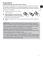
Thank you for purchasing this projector.
WARNING ►Before using this product, please read all manuals for this
product. Be sure to read “Safety Guide” rst. After reading them, store them in a
safe place for future reference.
About this manual
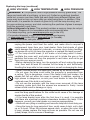
Various symbols are used in this manual. The meanings of these symbols are
described below.
WARNING This symbol indicates information that, if ignored, could possibly
result in personal injury or even death due to incorrect handling.
CAUTION This symbol indicates information that, if ignored, could possibly
result in personal injury or physical damage due to incorrect
handling.
NOTICE
This entry notices of fear of causing trouble.
Please refer to the pages written following this symbol.
NOTE • The information in this manual is subject to change without notice.
• The manufacturer assumes no responsibility for any errors that may appear in
this manual.
• The reproduction, transfer or copy of all or any part of this document is not
permitted without express written consent.
Trademark acknowledgment
• Mac® is a registered trademark of Apple Inc.
• Windows® is a registered trademark of Microsoft Corporation in the U.S. and/or other
countries.
• VESA and DDC are trademarks of the Video Electronics Standard Association.
• HDMI, the HDMI logo, and High-Denition Multimedia Interface are trademarks or registered
trademarks of HDMI Licensing LLC in the United States and other countries.
• Trademark PJLink is a trademark applied for trademark rights
in Japan, the United States of America and other countries and
areas.
All other trademarks are the properties of their respective owners.
1
Read this Safety Guide first.
Projector
User's Manual - Safety Guide
Thank you for purchasing this projector.
WARNING • Before using, read these user's manuals of this projector to ensure
correct usage through understanding. After reading, store them in a safe place for
future reference. Incorrect handling of this product could possibly result in personal injury
or physical damage. The manufacturer assumes no responsibility for any damage caused
by mishandling that is beyond normal usage defined in these manuals of this projector.
NOTE • The information in this manual is subject to change without notice.
• The manufacturer assumes no responsibility for any errors that may appear in
this manual.
• The reproduction, transmission or use of this document or contents is not
permitted without express written authority.
About The Symbols
Various symbols are used in this manual, the user’s manual and on the product
itself to ensure correct usage, to prevent danger to the user and others, and to
prevent property damage. The meanings of these symbols are described below.
It is important that you read these descriptions thoroughly and fully understand
the contents.
WARNING
CAUTION
This symbol indicates information that, if ignored, could
possibly result in personal injury or even death due to
incorrect handling.
This symbol indicates information that, if ignored, could
result possibly in personal injury or physical damage
due to incorrect handling.
Typical Symbols
This symbol indicates an additional warning (including cautions). An
illustration is provided to clarify the contents.
This symbol indicates a prohibited action. The contents will be clearly
indicated in an illustration or nearby (the symbol to the left indicates that
disassembly is prohibited).
This symbol indicates a compulsory action. The contents will be clearly
indicated in an illustration or nearby (the symbol to the left indicates that
the power plug should be disconnected from the power outlet).
1
Safety Precautions
WARNING
Never use the projector if a problem should occur.
Abnormal operations such as smoke, strange odor, no image, no sound,
excessive sound, damaged casing or elements or cables, penetration of
liquids or foreign matter, etc. can cause a fire or electrical shock.
In such case, immediately turn off the power switch and then disconnect the
power plug from the power outlet. After making sure that the smoke or odor
has stopped, contact your dealer. Never attempt to make repairs yourself
because this could be dangerous.
• The power outlet should be close to the projector and easily accessible.
Disconnect the
plug from the
power outlet.
Use special caution for children and pets.
Incorrect handling could result in fire, electrical shock, injury, burn or vision
problem.
Use special caution in households where children and pets are present.
Do not insert liquids or foreign object.
Penetration of liquids or foreign objects could result in fire or electrical shock.
Use special caution in households where children are present.
If liquids or foreign object should enter the projector, immediately turn off the
power switch, disconnect the power plug from the power outlet and contact
your dealer.
• Do not place the projector near water (ex. a bathroom, a beach, etc.).
• Do not expose the projector to rain or moisture. Do not place the projector
outdoors.
• Do not place flower vases, pots, cups, cosmetics, liquids such as water, etc
on or around the projector.
• Do not place metals, combustibles, etc on or around the projector.
• To avoid penetration of foreign objects, do not put the projector into a case
or bag together with any thing except the accessories of the projector,
signal cables and connectors.
Never disassemble and modify.
The projector contains high voltage components. Modification and/or disassembly of
the projector or accessories could result in fire or electrical shock.
• Never open the cabinet.
• Ask your dealer to repair and clean insider.
Do not give the projector any shock or impact.
If the projector should be shocked and/or broken, it could result in an injury,
and continued use could result in fire or electrical shock.
If the projector is shocked, immediately turn off the power switch, disconnect
the power plug from the power outlet and contact your dealer.
Do not place the projector on an unstable surface.
If the projector should be dropped and/or broken, it could result in an injury,
and continued use could result in fire or electrical shock.
• Do not place the projector on an unstable, slant or vibrant surface such as
a wobbly or inclined stand.
• Use the caster brakes placing the projector on a stand with casters.
• Do not place the projector in the side up position, the lens up position or
the lens down position.
• In the case of a ceiling installation or the like, contact your dealer before
installation.
2
Do not
disassemble.
Safety Precautions (continued)
WARNING
Be cautious of High temperatures of the projector.
High temperatures are generated when the lamp is lit. It could result in fire or
burn. Use special caution in households where children are present.
Do not touch about the lens, air fans and ventilation openings during use or
immediately after use, to prevent a burn. Take care of ventilation.
• Keep a space of 30 cm or more between the sides and other objects such
as walls.
• Do not place the projector on a metallic table or anything weak in heat.
• Do not place anything about the lens, air fans and ventilation openings of
the projector.
• Never block the air fan and ventilation openings.
• Do not cover the projector with a tablecloth, etc.
• Do not place the projector on a carpet or bedding.
Never look through the lens or openings when the lamp is on.
The powerful light could adversely affect vision.
Use special caution in households where children are present.
Use only the correct power cord and the correct power outlet.
Incorrect power supply could result in fire or electrical shock.
• Use only the correct power outlet depending on the indication on the
projector and the safety standard.
• The enclosed power cord must be used depending on the power outlet to
be used.
Be cautious of the power cord connection.
Incorrect connection of the power cord could result in fire or electrical shock.
• Do not touch the power cord with a wet hand.
• Check that the connecting portion of the power cord is clean (with no dust),
before using. Use a soft and dry cloth to clean the power plug.
• Insert the power plug into a power outlet firmly. Avoid using a loose,
unsound outlet or contact failure.
Be sure to connect with ground wire.
Connect the ground terminal of AC inlet of this unit with the ground terminal
provided at the building using the correct power cord; otherwise, fire or
electric shock can result.
• Don’t take the core of power cord away.
Surely connect
the ground wire.
3
Safety Precautions (continued)
WARNING
Be careful in handling the light source lamp.
The projector uses a high-pressure mercury glass lamp made of glass.
The lamp can break with a loud bang, or burn out. When the bulb bursts,
it is possible for shards of glass to fly into the lamp housing, and for gas
containing mercury to escape from the projector’s vent holes.
Please carefully read the section “Lamp”.
Be careful in handling the power cord and external connection
cables.
If you keep using a damaged the power cord or cables, it can cause a fire
or electrical shock. Do not apply too much heat, pressure or tension to the
power cord and cables.
If the power cord or cables is damaged (exposed or broken core wires, etc.),
contact your dealer.
• Do not place the projector or heavy objects on the power cord and cables.
Also, do not place a spread, cover, etc, over them because this could result
in the inadvertent placing of heavy objects on the concealed power cord or
cables.
• Do not pull the power cord and cables. When connecting and
disconnecting the power cord or cables, do it with your hand holding the plug
or connector.
• Do not place the cord near the heater.
• Avoid bending the power cord sharply.
• Do not attempt to work on the power cord.
Be careful in handling the battery of the remote control.
Incorrect handling of the battery could result in fire or personal injury. The
battery may explode if not handled properly.
• Keep the battery away from children and pets. If swallowed consult a
physician immediately for emergency treatment.
• Do not allow the battery in a fire or water.
• Avoid fire or high-temperature environment.
• Do not hold the battery with the metallic tweezers.
• Keep the battery in a dark, cool and dry play.
• Do not short circuit the battery.
• Do not recharge, disassemble or solder the battery.
• Do not give the battery a physical impact.
• Use only the battery specified in the other manual of this projector.
• Make sure the plus and minus terminals are correctly aligned when loading
the battery.
• If you observe a leakage of the battery, wipe out the flower and then
replace the battery. If the flower adheres your body or clothes, rinse well with
water.
• Obey the local laws on disposing the battery.
4
Safety Precautions (continued)
CAUTION
Be careful in moving the projector.
Neglect could result in an injury or damage.
• Do not move the projector during use. Before moving, disconnect the
power cord and all external connections, and close the slide lens door or
attach the lens cap.
• Avoid any impact or shock to the projector.
• Do not drag the projector.
• For moving the projector, use the enclosed case or bag if provided.
Do not put anything on top of the projector.
Placing anything on the projector could result in loss of balance or falling,
and cause an injury or damage. Use special caution in households where
children are present.
Do not attach anything other than specified things to the projector.
Neglect could result in an injury or damage.
• Some projector has a screw thread in a lens part. Do not attach anything
other than specified options (such as conversion lens) to the screw thread.
Avoid a smoky, humid or dusty place.
Placing the projector in a smoke, a highly humid, dusty place, oily soot or
corrosive gas could result in fire or electrical shock.
• Do not place the projector near a smoky, humid or dusty place (ex.
a smoking space, a kitchen, a beach, etc.). Do not place the projector
outdoors.
• Do not use a humidifier near the projector.
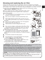
Take care of the air filter to normal ventilate.
The air filter should be cleaned periodically. If the air filter becomes clogged
by dust or the like, internal temperature rises and could cause malfunction.
The projector may display the message such as “CHECK THE AIR FLOW”
or turn off the projector, to prevent the internal heat level rising.
• When the indicators or a message prompts you to clean the air filter, clean
the air filter as soon as possible.
• If the soiling will not come off the air filter, or it becomes damaged, replace
the air filter.
• Use the air filter of the specified type only. Please order the air filter
specified in the other manual of this projector to your dealer.
• When you replace the lamp, replace also the air filter. The air filter may be
attached when you buy a replacement lamp for this projector.
• Do not turn on the projector without air filter.
Avoid a high temperature environment.
The heat could have adverse influence on the cabinet of the projector and
other parts. Do not place the projector, the remote control and other parts in
direct sunlight or near a hot object such as heater, etc.
Avoid Magnetism.
Manufacture strongly recommends to avoid any magnetic contact that is not
shielded or protected on or near the projector itself. (ie.,. Magnetic Security
Devices, or other projector accessory that contains magnetic material that has not
been provided by the manufacture etc.) Magnetic objects may cause interruption
of the projector's internal mechanical performance which may interfere with cooling
fans speed or stopping, and may cause the projector to completely shut down.
5
Safety Precautions (continued)
CAUTION
Remove the power cord for complete separation.
• For safety purposes, disconnect the power cord if the projector is not to be
used for prolonged periods of time.
• Before cleaning, turn off and unplug the projector. Neglect could result in
fire or electrical shock.
Disconnect the
plug from the
power outlet.
Ask your dealer to cleaning inside of the projector about every
year.
Accumulations of dust inside the projector cause result in fire or malfunction.
Cleaning inside is more effective if performed before every humid periods
such as rainy season.
• Do not clean inside yourself because it is dangerous.
NOTE
Do not give the remote control any physical impact.
A physical impact could cause damage or malfunction of the remote control.
• Take care not to drop the remote control.
• Do not place the projector or heavy objects on the remote control.
Take care of the lens.
• Close the slide lens door or attach the lens cap to prevent the lens surface being
scratched when the projector is not used.
• Do not touch the lens to prevent fog or dirt of the lens that cause deterioration of display
quality.
• Use commercially available lens tissue to clean the lens (used to clean cameras,
eyeglasses, etc.). Be careful not to scratch the lens with hard objects.
Take care of the cabinet and the remote control.
Incorrect care could have adverse influence such as discoloration, peeling paint, etc.
• Use a soft cloth to clean the cabinet and control panel of the projector and the remote
control. When excessively soiled dilute a neutral detergent in water, wet and wring out the
soft cloth and afterward wipe with a dry soft cloth. Do not use undiluted detergent directly.
• Do not use an aerosol sprays, solvents, volatile substances or abrasive cleaner.
• Before using chemical wipes, be sure to read and observe the instructions.
• Do not allow long-term close contact with rubber or vinyl.
About bright spots or dark spots.
Although bright spots or dark spots may appear on the screen, this is a unique characteristic of
liquid crystal displays, and such do not constitute or imply a machine defect.
Be careful of printing of the LCD panel.
If the projector continues projecting a still image, inactive images or 16:9 aspect images in
case of 4:3 panel, etc., for long time, the LCD panel might possibly be printed.
6
Safety Precautions (continued)
NOTE
About consumables.
Lamp, LCD panels, polarizors and other optical components, and air filter and cooling fans
have a different lifetime in each. These parts may need to be replaced after a long usage
time.
• This product isn’t designed for continuous use of long time. In the case of continuous use
for 6 hours or more, or use for 6 hours or more every day (even if it isn’t continuous), or
repetitious use, the lifetime may be shortened, and these parts may need to be replaced
even if one year has not passed since the beginning of using.
• Any inclining use beyond the adjustment range explained in these user’s manuals may
shorten the lifetimes of the consumables.
Before turning on the power, make the projector cool down adequately.
After turning the projector off, pushing the restart switch or interrupting of the power supply,
make the projector cool down adequately. Operation in a high temperature state of the
projector causes a damage of the electrode and un-lighting of the lamp.
Avoid strong rays.
Any strong ray (such as direct rays of the sun or room lighting) onto the remote control
sensors could invalidate the remote control.
Avoid radio interference.
Any interfering radiation could cause disordered image or noises.
• Avoid radio generator such as a mobile telephone, transceiver, etc. around the projector.
About displaying characteristic.
The display condition of the projector (such as color, contrast, etc.) depends on
characteristic of the screen, because the projector uses a liquid crystal display panel. The
display condition can differ from the display of CRT.
• Do not use a polarized screen. It can cause red image.
Turn the power on/off in right order.
To prevent any trouble, turn on/off the projector in right order mentioned below unless
specifying.
• Power on the projector before the computer or video tape recorder.
• Power off the projector after the computer or video tape recorder.
Take care not to fatigue your eyes.
Rest the eyes periodically.
Set the sound volume at a suitable level to avoid bothering other people.
• It is better to keep the volume level low and close the windows at night to protect the
neighborhood environment.
Connecting with notebook computer
When connecting with notebook computer, set to valid the RGB external image output
(setting CRT display or simultaneous display of LCD and CRT).
Please read instruction manual of the notebook for more information.
7
Lamp
WARNING
HIGH VOLTAGE
HIGH TEMPERATURE
HIGH PRESSURE
The projector uses a high-pressure mercury glass lamp. The lamp can break with a
loud bang, or burn out, if jolted or scratched, handled while hot, or worn over time.
Note that each lamp has a different lifetime, and some may burst or burn out soon after
you start using them. In addition, when the bulb bursts, it is possible for shards of
glass to fly into the lamp housing, and for gas containing mercury to escape from the
projector’s vent holes.
About disposal of a lamp • This product contains a mercury lamp; do not put in trash.
Dispose of in accord with environmental laws.
For lamp recycling, go to www.lamprecycle.org. (in USA)
For product disposal, contact your local government agency or www.eiae.org (in the US)
or www.epsc.ca (in Canada).
For more information, call your dealer.
Disconnect
the plug from
the power
outlet
• If the lamp should break (it will make a loud bang when it does), unplug
the power cord from the outlet, and make sure to request a replacement
lamp from your local dealer. Note that shards of glass could damage the
projector’s internals, or cause injury during handling, so please do not try to
clean the projector or replace the lamp yourself.
• If the lamp should break (it will make a loud bang when it does), ventilate
the room well, and make sure not to breathe the gas that comes out of the
projector vents, or get it in your eyes or mouth.
• Before replacing the lamp, make sure the power switch is off and the
power cable is not plugged in, then wait at least 45 minutes for the lamp to
cool sufficiently. Handling the lamp while hot can cause burns, as well as
damaging the lamp.
• Do not open the lamp cover while the projector is suspended from above.
This is dangerous, since if the lamp’s bulb has broken, the shards will
fall out when the cover is opened. In addition, working in high places is
dangerous, so ask your local dealer to have the lamp replaced even if the
bulb is not broken.
• Do not use the projector with the lamp cover removed. At the lamp
replacing, make sure that the screws are screwed in firmly. Loose screws
could result in damage or injury.
• Use the lamp of the specified type only.
• If the lamp breaks soon after the first time it is used, it is possible that
there are electrical problems elsewhere besides the lamp. If this happens,
contact your local dealer or a service representative.
• Handle with care: jolting or scratching could cause the lamp bulb to burst
during use.
• Using the lamp for long periods of time, could cause it dark, not to light up
or to burst. When the pictures appear dark, or when the color tone is poor,
please replace the lamp as soon as possible. Do not use old (used) lamps;
this is a cause of breakage.
8
Regulatory Notices
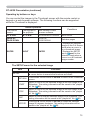
FCC Statement Warning
This device complies with part 15 of the FCC Rules. Operation is subject to the following
two conditions: (1) This device may not cause harmful interference, and (2) this device
must accept any interference received, including interference that may cause undesired
operation.
WARNING: This equipment has been tested and found to comply with the limits for a
Class B digital device, pursuant to Part 15 of the FCC Rules. These limits are designed
to provide reasonable protection against harmful interference in a residential installation.
This equipment generates, uses, and can radiate radio frequency energy and, if not
installed and used in accordance with the instructions, may cause harmful interference
to radio communications. However, there is no guarantee that interference will not occur
in a particular installation. If this equipment does cause harmful interference to radio
or television reception, which can be determined by turning the equipment off and on,
the user is encouraged to try to correct the interference by one or more of the following
measures:
- Reorient or relocate the receiving antenna.
- Increase the separation between the equipment and receiver.
- Connect the equipment into an outlet on a circuit different from that to which the receiver
is connected.
- Consult the dealer or an experienced radio/TV technician for help.
INSTRUCTIONS TO USERS: This equipment complies with the requirements of FCC
(Federal Communication Commission) equipment provided that the following conditions
are met. Some cables have to be used with the core set. Use the accessory cable or a
designated-type cable for the connection. For cables that have a core only at one end,
connect the core to the projector.
CAUTION: Changes or modifications not expressly approved by the party responsible for
compliance could void the user’s authority to operate the equipment.
For the Customers in CANADA
NOTICE: This Class B digital apparatus complies with Canadian ICES-003.
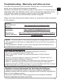
Warranty And After-Service
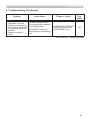
Unless seen any abnormal operations (mentioned with the first paragraph of
WARNING in this manual), when a problem occurs with the equipment, first refer to the
“Troubleshooting” section of the “Operating Guide”, and run through the suggested checks.
If this does not resolve the problem contact your dealer or service company. They will tell
you what warranty condition is applied.
9
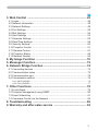
Contents
Introduction . . . . . . . . . . . . . . . 3
Features . . . . . . . . . . . . . . . . . . . . . . 3
Checking the contents of package . . . 3
Part names . . . . . . . . . . . . . . . . . . . . 4
Setting up . . . . . . . . . . . . . . . . . 7
Arrangement . . . . . . . . . . . . . . . . . . . 7
Connecting with your devices . . . . . . 9
Connecting to a power supply. . . . . 14
Using the security bar and slot . . . . 14
Remote control . . . . . . . . . . . . 15
Installing the batteries . . . . . . . . . . . 15
About the remote control signal . . . 15
Changing the frequency of remote control signal . . 16
Using as a simple PC mouse & keyboard . . 16
Power on/off . . . . . . . . . . . . . . 17
Turning on the power . . . . . . . . . . . 17
Turning off the power . . . . . . . . . . . 17
Operating . . . . . . . . . . . . . . . . 18
Adjusting the volume. . . . . . . . . . . . 18
Temporarily muting the sound . . . . . 18
Selecting an input signal . . . . . . . . . 18
Searching an input signal . . . . . . . . 20
Selecting an aspect ratio. . . . . . . . . 20
Adjusting the projector's elevator . . 21
Adjusting the zoom and focus . . . . . 21
Using the automatic adjustment feature . . . 22
Adjusting the position . . . . . . . . . . . 22
Correcting the keystone distortions . . 23
Using the magnify feature . . . . . . . . 24
Temporarily freezing the screen . . . 25
Temporarily blanking the screen . . 25
Using the menu function . . . . . . . . 26
EASY MENU. . . . . . . . . . . . . . . 28
ASPECT, AUTO KEYSTONE , KEYSTONE,
PICTURE MODE, ECO MODE, MIRROR, RESET,
FILTER TIME, LANGUAGE, ADVANCED MENU, EXIT
PICTURE menu . . . . . . . . . . . . 30
BRIGHTNESS, CONTRAST, GAMMA, COLOR TEMP,
COLOR, TINT, SHARPNESS, ACTIVE IRIS, MY MEMORY
IMAGE menu . . . . . . . . . . . . . . 33
ASPECT, OVER SCAN, V POSITION, H POSITION,
H PHASE, H SIZE, AUTO ADJUST EXECUTE
INPUT menu . . . . . . . . . . . . . . 36
PROGRESSIVE, VIDEO NR, COLOR SPACE,
COMPONENT, VIDEO FORMAT, HDMI FORMAT,
HDMI RANGE, COMPUTER IN,
FRAME LOCK, RESOLUTION
SETUP menu . . . . . . . . . . . . . . 40
AUTO KEYSTONE, KEYSTONE, AUTO ECO MODE,
ECO MODE, MIRROR, STANDBY MODE,
MONITOR OUT
AUDIO menu . . . . . . . . . . . . . . 42
VOLUME, SPEAKER, AUDIO SOURCE,
HDMI AUDIO, MIC LEVEL, MIC VOLUME
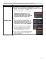
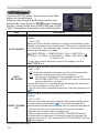
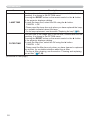
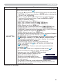
SCREEN menu . . . . . . . . . . . . . 44
LANGUAGE, MENU POSITION, BLANK,
START UP, MyScreen, MyScreen Lock,
MESSAGE, SOURCE NAME, TEMPLATE, C.C.
OPTION menu . . . . . . . . . . . . . 50
AUTO SEARCH, AUTO KEYSTONE,
DIRECT POWER ON, AUTO POWER OFF,
USB TYPE B, LAMP TIME, FILTER TIME,
MY BUTTON, MY SOURCE, SERVICE
NETWORK menu . . . . . . . . . . . 60
SETUP, PROJECTOR NAME, MY IMAGE,
AMX D.D., PRESENTATION, INFORMATION,
SERVICE
SECURITY menu . . . . . . . . . . . 67
SECURITY PASSWORD CHANGE,
MyScreen PASSWORD, PIN LOCK,
TRANSITION DETECTOR, MY TEXT PASSWORD,
MY TEXT DISPLAY, MY TEXT WRITING
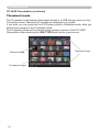
Presentation tools . . . . . . . . . 73
PC-LESS Presentation . . . . . . . 73
Thumbnail Mode, Full Screen Mode,
Slideshow mode, Playlist
USB Display . . . . . . . . . . . . . 82
Right-Click menu, Floating menu,
Options window
Maintenance . . . . . . . . . . . . . . 85
Replacing the lamp . . . . . . . . . . . . . 85
Cleaning and replacing the air lter . . 87
Replacing the internal clock battery . . 89
Other care . . . . . . . . . . . . . . . . . . . . 90
Troubleshooting . . . . . . . . . . . 91
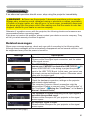
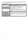
Related messages . . . . . . . . . . . . . 91
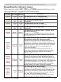
Regarding the indicator lamps . . . . 93
Shutting the projector down . . . . . . 94
Resetting all settings . . . . . . . . . . . . 94
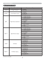
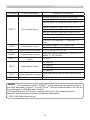
Phenomena that may be easy
to be mistaken for machine defects . . 95
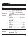
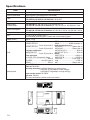
Specifications . . . . . . . . . . . . . 99
2
Introduction
Introduction
Features
The projector provides you with the broad use by the following features.
9 This projector has a variety of I/O ports that supposedly cover for any
business scene. The HDMI port can support various image equipment
which have digital interface to get clearer pictures on a screen.
9 This projector realizes the large projection image, even if in a small space.
9 If you insert a USB storage device, such as a USB memory, into the USB
TYPE A port and select the port as the input source, you can view images
stored in the device.
9 This projector can be controlled and monitored via LAN connection.
9 This projector's network supports the PJLinkTM standard.
9 PJLinkTM is a unied standard for operating and controlling data projectors.
PJLinkTM enables central control of projectors manufactured by different vendors
and projectors can be operated by a controller. PJLinkTM compliant equipment
can be managed and controlled at any time and in any place, regardless of
manufacturer.
For the command of PJLinkTM, see “Technical”.
For specications of PJLinkTM, see the web site of the Japan Business Machine
and Information System Industries Association.
URL: http://pjlink.jbmia.or.jp (as of Dec. 2009)
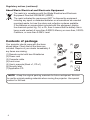
Checking the contents of package
Please see the Contents of package section in the User’s Manual (concise)
which is a book. Your projector should come with the items shown there. Require
of your dealer immediately if any items are missing.
NOTE • Keep the original packing materials, for future reshipment. Be sure
to use the original packing materials when moving the projector. Use special
caution for the lens.
3
Introduction
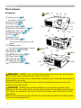
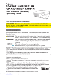
Part names
HOT! (1)
Projector
(2) (3)
(4)
(1) Lamp cover (85)
The lamp unit is inside.
(2) Focus ring (21)
(3) Zoom ring (21)
(4) Control panel (5)
(5) Elevator buttons (x 2) (21)
(6) Elevator feet (x 2) (21)
(7) Remote sensor (15)
(8) Lens (90)
(9) Intake vents
(10) Filter cover (87)
(12)
(7)
(6)
(8)
(9)
(11)
(5)
(6)
(10)
(6)
(6)
The air lter and intake vent are
inside.
(11) Battery cover
The internal clock battery is inside.
(12) Speaker (12, 18, 42)
(13) Exhaust vent
(14) AC IN (AC inlet) (14)
(15) Rear panel (5)
(16) Security bar (14)
(17) Security slot (14)
(18) Shutdown switch (94)
(12)
HOT! (13)
(4)
(18)
(15)
(1)
(14)
(16)
(17)
HOT!
(15)
HOT! (13)
WARNING ►HOT! : Do not touch around the lamp cover and the exhaust
vents during use or just after use, since it is too hot.
►Do not look into the lens or vents while the lamp is on, since the strong light is
not good for your eyes.
►Do not handle the elevator buttons without holding the projector, since the
projector may drop down.
CAUTION ►Maintain normal ventilation to prevent the projector from
heating up. Do not cover, block or plug up the vents. Do not place anything that
can stick or be sucked to the vents, around the intake vents. Clean the air lter
periodically.
►Do not use the security bar and slot to prevent the projector from falling down,
since it is not designed for it.
4
Introduction
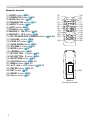
Control panel
(1) STANDBY/ON button (17)
(2) INPUT button (18)
(3) MENU button (26)
(5) (6)
It consists of four cursor buttons.
(4) POWER indicator (17, 93, 94)
(5) TEMP indicator (93, 94)
(6) LAMP indicator (93, 94)
(1)
(2)
(3)
(4)
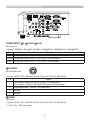
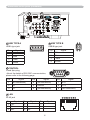
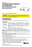
Rear panel (9 ~ 13)
(1) USB TYPE A port
(2) LAN port
(3) HDMI port
(4) USB TYPE B port
(5) MIC port
(6) AUDIO IN1 port
(7) AUDIO IN2 port
(8) AUDIO IN3(L,R) ports
(9) AUDIO OUT (L,R) ports
(1)
(2)
(10) COMPUTER IN1 port
(11) COMPUTER IN2 port
(12) MONITOR OUT port
(13) CONTROL port
(14) VIDEO port
(15) S-VIDEO port
(16) Cr/Pr,Cb/Pb,Y
(Component) ports
HDMI
USB
TYPE A
DC5V 0.5A
(4)
(3)
(10)
(11)
(12)
USB
TYPE B
LAN
(5)
MIC
IN1
IN2
(6) (7)
(8)
(9)
(16)
(15) (14)
(13)
CAUTION ►Use the shutdown switch only when the projector is not
turned off by normal procedure, since pushing this switch stops operation of the
projector without cooling it down.
5
Introduction
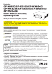
Remote control
(1) VIDEO button (19)
(2) COMPUTER button (19)
(3) SEARCH button (20)
(4) STANDBY/ON button (17)
(5) ASPECT button (20)
(6) AUTO button (22)
(7) BLANK button (25)
(8) MAGNIFY - ON button (24)
(9) MAGNIFY - OFF button (24)
(10) MY SOURCE/DOC.CAMERA button (19, 54)
(11) VOLUME - button (18)
(12) PAGE UP button (16)
(13) PAGE DOWN button (16)
(14) VOLUME + button (18)
(15) MUTE button (18)
(16) FREEZE button (25)
(17) MY BUTTON - 1 button (53)
(18) MY BUTTON - 2 button (53)
(19) KEYSTONE button (23)
(20) POSITION button (22, 27)
(21) MENU button (26, 27)
(22) ▲/▼/◄/► cursor buttons (26, 27)
(23) ENTER button (26, 27)
(24) ESC button (27)
(25) RESET button (27)
(26) Battery cover (15)
(2)
(1)
(6)
(5)
(16)
(8)
(9)
(19)
(17)
(20)
(22)
VIDEO
ASPECT
MAGNIFY
MY SOURCE/
COMPUTER DOC.CAMERA
AUTO
FREEZE
SEARCH
BLANK
PAGE
UP
VOLUME
㧗
ON
DOWN
OFF
KEYSTONE
MY BUTTON
1
MUTE
2
MENU
POSITION
ENTER
ESC
RESET
(24)
(26)
Back of
the remote control
6
(10)
(4)
(3)
(7)
(12)
(14)
(11)
(13)
(15)
(18)
(21)
(23)
(25)
Setting up
Setting up
Install the projector according to the environment and manner the projector will be
used in.
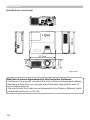
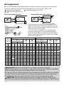
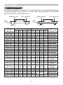
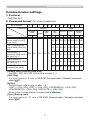
Arrangement
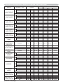
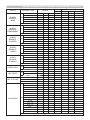
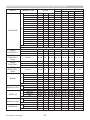
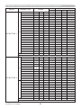
Refer to the illustrations and tables below to determine screen size and projection
distance.
The values shown in the table are calculated for a full size screen: 1024 x 768
a Screen size (diagonal)
b Projection distance (±10%)
c1 , c2 Screen height (±10%)
On a horizontal surface
Suspended from the ceiling
• Keep a space of 30 cm or more between the
sides of the projector and other objects such
as walls.
• For the case of installation in a special
state such as ceiling mount, the specied
mounting accessories (99) and service may
be required. Before installing the projector,
consult your dealer about your installation.
a
Screen size
(diagonal)
4 : 3 screen
b
c1
Projection distance
Screen
height
min.
max.
type
(inch)
m
m
30
40
50
60
70
80
90
100
120
150
200
250
300
0.8
1.0
1.3
1.5
1.8
2.0
2.3
2.5
3.0
3.8
5.1
6.4
7.6
0.9
1.2
1.5
1.8
2.1
2.4
2.7
3.0
3.6
4.5
6.0
7.5
9.1
inch
m
34 1.0
46 1.4
58 1.8
70 2.1
82 2.5
94 2.8
106 3.2
118 3.6
142 4.3
178 5.3
237 7.1
297 8.9
357 10.7
c2
Screen
height
16 : 9 screen
b
c1
Projection distance
Screen
height
min.
max.
inch
cm
inch
cm
inch
m
41
55
69
83
97
112
126
140
168
211
281
352
422
41
16
55
22
69
27
82
32
96
38
110 43
123 49
137 54
165 65
206 81
274 108
343 135
411 162
5
6
8
9
11
12
14
15
18
23
30
38
46
2
2
3
4
4
5
5
6
7
9
12
15
18
1.0
1.3
1.6
1.9
2.3
2.6
2.9
3.3
3.9
4.9
6.6
8.2
9.9
(continued on next page)
inch
m
38 1.1
51 1.5
64 1.9
77 2.3
90 2.7
103 3.1
116 3.5
129 3.9
155 4.7
194 5.8
259 7.8
324 9.7
389 11.7
c2
Screen
height
inch
cm
inch
cm
inch
45
60
76
91
106
122
137
153
183
229
306
383
460
39
15
51
20
64
25
77
30
90
35
103 41
116 46
129 51
154 61
193 76
257 101
322 127
386 152
-1
-2
-2
-2
-3
-3
-4
-4
-5
-6
-8
-10
-12
0
-1
-1
-1
-1
-1
-1
-2
-2
-2
-3
-4
-5
7
Setting up
Arrangement (continued)
WARNING ►Place the projector in a stable horizontal position. If the
projector falls or is knocked over, it could cause injury and/or damage to the
projector. Using a damaged projector could then result in re and/or electric
shock.
• Do not place the projector on an unstable, slanted or vibrational surface such
as a wobbly or inclined stand.
• Do not place the projector on its side, front or rear position.
• Consult with your dealer before a special installation such as suspending from
a ceiling or somewhere else.
►Place the projector in a cool place, and ensure that there is sufcient
ventilation. The high temperature of the projector could cause re, burns and/or
malfunction of the projector.
• Do not stop-up, block or otherwise cover the projector's vents.
• Keep a space of 30 cm or more between the sides of the projector and other
objects such as walls.
• Do not place or attach anything that would block the lens or vent holes.
• Do not place the projector on metallic thing or anything weak in heat.
• Do not place the projector on carpet, cushions or bedding.
• Do not place the projector in direct sunlight or near hot objects such as heaters.
• Do not place anything near the projector lens or vents, or on top of the
projector.
• Do not place anything that may be sucked into or stick to the vents on the
bottom of the projector. This projector has some intake vents also on the
bottom.
►Do not place the projector anyplace where it may get wet. Getting the projector
wet or inserting liquid into the projector could cause re, electric shock and/or
malfunction of the projector.
• Do not place the projector in a bathroom or the outdoors.
• Do not place anything containing liquid near the projector.
►Use only the mounting accessories the manufacturer specied, and leave
installing and removing the projector with the mounting accessories to the
service personnel.
• Read and keep the user’s manual of the mounting accessories used.
CAUTION ►Avoid placing the projector in smoky, humid or dusty place.
Placing the projector in such places could cause re, electric shock and/or
malfunction of the projector.
• Do not place the projector near humidiers, smoking spaces or a kitchen.
►Position the projector to prevent light from directly hitting the projector's remote
sensor.
►Do not place the product in a place where radio interference may be caused.
►Do not place this product in a magnetic eld.
8
Setting up
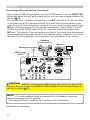
Connecting with your devices
Before connecting the projector to a device, consult the manual of the device to
conrm that the device is suitable for connecting with this projector and prepare
the required accessories, such as a cable in accord with the signal of the device.
Consult your dealer when the required accessory did not come with the product or
the accessory is damaged.
After making sure that the device and projector are turned off, connect them
following the instructions below.
WARNING ►Use only the appropriate accessories. Otherwise it could cause
a re or damage to the device and the projector.
- Use only the accessories specified or recommended by the projector’s
manufacturer. Consult your dealer when the required accessory did not come
with the product or the accessory is damaged. It may be regulated under some
standard.
- For a cable with a core at only one end, connect the end with the core to the
projector. That may be required by EMI regulations.
- Neither disassemble nor modify the projector and the accessories.
- Do not use the damaged accessory. Be careful not to damage the accessories.
Route a cable so that it is neither stepped on nor pinched out.
CAUTION ►Do not turn on or off the projector while connected to a device
in operation, unless that is directed in the manual of the device. Otherwise it may
cause malfunction in the device or projector.
►Be careful not to mistakenly connect a connector to a wrong port. Otherwise it
may cause malfunction in the device or projector.
- When connecting a connector to a port, make sure that the shape of the
connector ts the port.
- Tighten the screws to connect a connector equipped with screws to a port.
- Use the cables with straight plugs, not L-shaped ones, as the input ports of the
projector are recessed.
About Plug-and-Play capability
• Plug-and-Play is a system composed of a computer, its operating system
and peripheral equipment (i.e. display devices). This projector is VESA DDC
2B compatible. Plug-and-Play can be used by connecting this projector to a
computer that is VESA DDC (display data channel) compatible.
- Take advantage of this feature by connecting a computer cable to the
COMPUTER IN1 port (DDC 2B compatible). Plug-and-Play may not work
properly if any other type of connection is attempted.
- Please use the standard drivers in your computer as this projector is a Plug-andPlay monitor.
(continued on next page)
9
Setting up
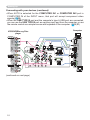
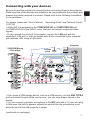
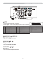
Connecting with your devices (continued)
• When AUTO is selected for the COMPUTER IN1 or COMPUTER IN2 port in
COMPUTER IN of the INPUT menu, that port will accept component video
signals (38).
• When the USB TYPE B port and the computer's type A USB port are connected,
you can use the USB TYPE B port as a picture input port from the computer, or use
the remote control as a simple mouse and keyboard of the computer. (16, 51).
Computer
Cb/Pb Cr/Pr
AUDIO
OUT
L
R
USB
TYPE B
COMPUTER IN1
VIDEO
LAN
R
AUDIO
OUT
R
L S-VIDEO
(continued on next page)
10
MIC
IN1
IN2
AUDIO
L
L
IN3
OUT
Cb/Pb
R
R
Y
Cr/Pr
S-VIDEO
CONTROL
RS-232C
AUDIO
OUT
L
MONITOR OUT
DISPLAY
VIDEO
COMPUTER
IN2
HDMI
USB
TYPE A
DC5V 0.5A
AUDIO USB
(A)
OUT
Y
HDMI
COMPONENT
VCR/DVD/Blu-ray Disc
player
Setting up
Connecting with your devices (continued)
NOTE • Before connecting the projector to a computer, consult the computer’s
manual and check the compatibility of the signal level, the synchronization
methods and the display resolution output to the projector.
- Some signal may need an adapter to input this projector.
- Some computers have multiple screen display modes that may include some
signals which are not supported by this projector.
- Although the projector can display signals with resolution up to UXGA
(1600X1200), the signal will be converted to the projector’s panel resolution
before being displayed. The best display performance will be achieved if the
resolutions of the input signal and the projector panel are identical.
• If you connect this projector and a notebook computer, you need output the
display to an external monitor, or output simultaneously to the internal display
and an external monitor. Consult the computer's manual for the setting.
• Depending on the input signal, the automatic adjustment function of this
projector may take some time and not function correctly.
- Note that a composite sync signal or sync-on-green signal may confuse the
automatic adjustment function of this projector (38).
- If the automatic adjustment function does not work correctly, you may not see
the dialog to set the display resolution. In such a case, use an external display
device. You may be able to see the dialog and set an appropriate display
resolution.
(continued on next page)
11
Setting up
Connecting with your devices (continued)
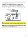
• If you insert a USB storage device, such as a USB memory, into the USB TYPE
A port and select the port as the input source, you can view images stored in the
device (73).
• You can connect a dynamic microphone to the MIC port with a 3.5 mm mini-plug.
In that case, the built-in speaker outputs the sound from the microphone, even
while the sound from the projector is output. You can input line level signal to the
MIC port from equipment such as wireless microphone. Select HIGH in the MIC
LEVEL item of the AUDIO menu when you input line level audio signal to the
MIC port. The volume of the microphone and that of the sound from the projector
can be controlled separately except for the standby mode. However, if you mute
the sound from the projector, the sound from the microphone is also muted.
Speakers
(with an amplier)
Microphone system
R
Monitor
RGB IN
L
USB storage
device
COMPUTER
IN2
HDMI
USB
TYPE A
DC5V 0.5A
USB
TYPE B
COMPUTER IN1
VIDEO
LAN
MONITOR OUT
MIC
IN1
IN2
AUDIO
L
L
IN3
OUT
Cb/Pb
R
R
Y
Cr/Pr
S-VIDEO
CONTROL
CAUTION ►Before removing the USB storage device from the port of the
projector, be sure to use the REMOVE USB function on the thumbnail screen to
secure your data (76).
NOTE • If a loud feedback noise is produced from the speaker, move the
microphone away from the speaker.
• This projector doesn't support plug-in power for the microphone.
(continued on next page)
12
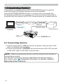
Setting up
Connecting with your devices (continued)
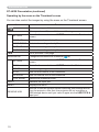
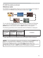
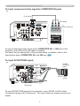
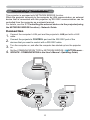
To use network functions of the projector, connect the LAN port with the
computer's LAN port, or with an access point that is connected to the computer
with wireless LAN, using a LAN cable. To use NETWORK BRIDGE function,
also connect the CONTROL port and an RS-232C port of the external device to
communicate as a network terminal. See the User's Manual - Network Guide for
details of the network functions.
Computer
Access point
RS-232C
COMPUTER
IN2
HDMI
USB
TYPE A
DC5V 0.5A
LAN
USB
TYPE B
COMPUTER IN1
VIDEO
LAN
MONITOR OUT
MIC
IN1
IN2
AUDIO
L
L
IN3
OUT
Cb/Pb
R
R
Y
Cr/Pr
S-VIDEO
CONTROL
CAUTION ►Before connecting the projector to a network system be sure
to obtain the consent of the administrator of the network (60).
►Do not connect the LAN port to any network that might have the excessive voltage.
NOTE • If an oversized USB storage device blocks the LAN port, use a USB
extension cable to connect the USB storage device.
13
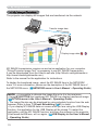
Setting up
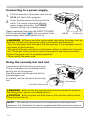
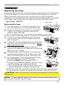
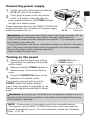
Connecting to a power supply
the connector of the power cord into the
1. Put
AC IN (AC inlet) of the projector.
plug the power cord’s plug into the
2. Firmly
outlet. In a couple of seconds after the
power supply connection, the POWER
indicator will light up in steady orange.
Please remember that when the DIRECT POWER
ON function activated (50), the connection of the
power supply make the projector turn on.
AC IN
Power cord
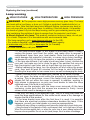
WARNING ►Please use extra caution when connecting the power cord, as
incorrect or faulty connections may result in re and/or electrical shock.
• Only use the power cord that came with the projector. If it is damaged, consult
your dealer to get a new one.
• Only plug the power cord into an outlet whose voltage is matched to the power
cord. The power outlet should be close to the projector and easily accessible.
Remove the power cord for complete separation.
• Never modify the power cord.
Using the security bar and slot
A commercial anti-theft chain or wire up to
10 mm in diameter can be attached to the
security bar on the projector.
Also this product has the security slot for
the Kensington lock.
For details, see the manual of the security
tool.
Security slot
Security bar
Anti-theft chain or wire
WARNING ►Do not use the security bar and slot to prevent the projector
from falling down, since it is not designed for it.
CAUTION ►Do not place anti-theft chain or wire near the exhaust vents.
It may become too hot.
NOTE • The security bar and slot is not comprehensive theft prevention
measures. It is intended to be used as supplemental theft prevention measure.
14
Remote control
Remote control
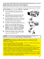
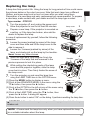
Installing the batteries
Please insert the batteries into the remote control before using it. If the remote control
starts to malfunction, try to replace the batteries. If you will not use the remote control for
long period, remove the batteries from the remote control and store them in a safe place.
Holding the hook part of the battery
1
2
3
cover, remove it.
Align and insert the two AA batteries
(HITACHI MAXELL, Part No.LR6 or R6P)
according to their plus and minus terminals
as indicated in the remote control.
Replace the battery cover in the direction of the arrow and snap it back into place.
1.
2.
3.
WARNING ►Always handle the batteries with care and use them only as
directed. Improper use may result in battery explosion, cracking or leakage,
which could result in re, injury and/or pollution of the surrounding environment.
• Be sure to use only the batteries specied. Do not use batteries of different
types at the same time. Do not mix a new battery with used one.
• Make sure the plus and minus terminals are correctly aligned when loading a battery.
• Keep a battery away from children and pets.
• Do not recharge, short circuit, solder or disassemble a battery.
• Do not place a battery in a re or water. Keep batteries in a dark, cool and dry place.
• If you observe battery leakage, wipe out the leakage and then replace a battery.
If the leakage adheres to your body or clothes, rinse well with water immediately.
• Obey the local laws on disposing the battery.
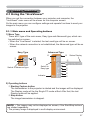
About the remote control signal
The remote control works with the projector’s remote
sensor. This projector has a remote sensor on the front.
The sensor senses the signal within the following range
when the sensor is active:
60 degrees (30 degrees to the left and right of the sensor)
within 3 meters about.
Approx.
3m
30º 30º
NOTE • The remote control signal reected in the screen or the like may be available.
If it is difcult to send the signal to the sensor directly, attempt to make the signal reect.
• The remote control uses infrared light to send signals to the projector (Class 1
LED), so be sure to use the remote control in an area free from obstacles that
could block the remote control’s signal to the projector.
• The remote control may not work correctly if strong light (such as direct sun
light) or light from an extremely close range (such as from an inverter uorescent
lamp) shines on the remote sensor of the projector. Adjust the position of
projector avoiding those lights.
15
Remote control
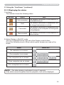
Changing the frequency of remote control signal
The accessory remote control has the two choices on signal
frequency Mode 1:NORMAL and Mode 2:HIGH. If the remote control
does not function properly, attempt to change the signal frequency.
In order to set the Mode, please keep pressing the combination of
two buttons listed below simultaneously for about 3 seconds.
(2)
(1) Set to Mode 1:NORMAL... VOLUME - and RESET buttons
(2) Set to Mode 2:HIGH... MAGNIFY OFF and ESC buttons
Please remember that the REMOTE FREQ. in the SERVICE item of
the OPTION menu (56) of the projector to be controlled should be
set to the same mode as the remote control.
VIDEO
ASPECT
MAGNIFY
MY SOURCE/
COMPUTER DOC.CAMERA
AUTO
FREEZE
SEARCH
BLANK
PAGE
UP
VOLUME
㧗
ON
DOWN
OFF
KEYSTONE
MY BUTTON
1
(1)
MUTE
2
MENU
POSITION
ENTER
RESET
ESC
Using as a simple PC mouse & keyboard
The accessory remote control works as a simple mouse
and keyboard of the computer, when the projector’s USB
TYPE B port and the computer’s type A USB port are
connected and MOUSE is selected for the USB TYPE B
item in the OPTION menu (51).
(1) PAGE UP key: Press PAGE UP button.
(2) PAGE DOWN key: Press PAGE DOWN button.
(3) Mouse left button: Press ENTER button.
(4) Move pointer: Use the cursor buttons ▲, ▼, ◄ and ►.
(5) ESC key: Press ESC button.
(6) Mouse right button: Press RESET button.
WARNING ►Improper use of the simple mouse &
keyboard function could damage your equipment. While
using this function, please connect this product only to
a computer. Be sure to check your computer’s manuals
before connecting this product to the computer.
USB
TYPE B
VIDEO
USB port
ASPECT
MAGNIFY
MY SOURCE/
COMPUTER DOC.CAMERA
AUTO
FREEZE
BLANK
PAGE
UP
VOLUME
㧗
DOWN
OFF
KEYSTONE
(3)
(1)
SEARCH
ON
MY BUTTON
1
MENU
POSITION
(2)
MUTE
2
(4)
ENTER
ESC
(5)
RESET
(6)
NOTE • When the simple mouse & keyboard function of this product does not
work correctly, please check the following.
- When a USB cable connects this projector with a computer having a built-in
pointing device (e.g. track ball) like a laptop PC, open BIOS setup menu, then
select the external mouse and disable the built-in pointing device, because the
built-in pointing device may have priority to this function.
- Windows 95 OSR 2.1 or higher is required for this function. And also this function may
not work depending on the computer’s congurations and mouse drivers. This function
can work with the computer which can operate general USB mouse or keyboard.
- You cannot do things like press two buttons at once (for instance, pressing
two buttons at the same time to move the mouse pointer diagonally).
- This function is activated only when the projector is working properly. This function
is not available while the lamp is warming up (the POWER indicator blinks green),
and while adjusting the volume and display, correcting for keystone, zooming in on
the screen, using the BLANK function, or displaying the menu screen.
16
Power on/off
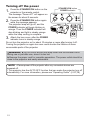
Power on/off
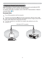
Turning on the power
sure that the power cord is rmly and
1. Make
correctly connected to the projector and the
STANDBY/ON button
POWER indicator
outlet.
Make sure that the POWER indicator is
steady orange (93). Then remove the lens
cover.
Press STANDBY/ON button on the
projector or the remote control.
The projection lamp will light up and POWER
indicator will begin blinking in green. When the
power is completely on, the indicator will stop blinking and light in steady
green (93).
To display the picture, select an input signal according to the section “Selecting an
input signal” (18).
2.
VIDEO
ASPECT
MAGNIFY
3.
MY SOURCE/
COMPUTER DOC.CAMERA
AUTO
FREEZE
SEARCH
BLANK
PAGE
UP
VOLUME
㧗
ON
DOWN
OFF
KEYSTONE
MY BUTTON
1
MUTE
2
MENU
POSITION
ENTER
ESC
RESET
Turning off the power
the STANDBY/ON button on the projector or the remote control.
1. Press
The message “Power off?” will appear on the screen for about 5 seconds.
the STANDBY/ON button again while the message appears.
2. Press
The projector lamp will go off, and the POWER indicator will begin blinking in
3.
orange. Then POWER indicator will stop blinking and light in steady orange
when the lamp cooling is complete (93).
Attach the lens cover, after the POWER indicator turns in steady orange.
Do not turn the projector on for about 10 minutes or more after turning it off.
Turning the projector on again too soon could shorten the lifetime of some
consumable parts of the projector.
WARNING ►A strong light is emitted when the projector’s power is on.
Do not look into the lens of the projector or look inside of the projector through
any of the projector’s openings.
►Do not touch around the lamp cover and the exhaust vents during use or just
after use, since it is too hot.
NOTE • Turn the power on/off in right order. Please power on the projector
prior to the connected devices.
• This projector has the function that can make the projector automatically turn on/
off. Please refer to the DIRECT POWER ON (50) and AUTO POWER OFF (51)
items of the OPTION menu.
• Use the shutdown switch (94) only when the projector is not turned off by
normal procedure.
17
Operating
Operating
VOLUME +/- button
Adjusting the volume
VIDEO
1.
MY SOURCE/
COMPUTER DOC.CAMERA
Use the VOLUME +/VOLUME - buttons to adjust the volume.
A dialog will appear on the screen to aid you in adjusting the
volume. If you do not do anything, the dialog will automatically
disappear after a few seconds.
● When is selected for current picture input port, the volume adjustment is
disabled. Please see AUDIO SOURCE item of AUDIO menu (42).
● Even if the projector is in the standby state, the volume is adjustable when
both of the following conditions are true:
- An option other than is selected for STANDBY in the AUDIO SOURCE
item of the AUDIO menu (42).
- NORMAL is selected in the STANDBY MODE item of the SETUP menu (42).
ASPECT
MAGNIFY
AUTO
FREEZE
SEARCH
BLANK
PAGE
UP
VOLUME
㧗
ON
DOWN
OFF
KEYSTONE
MY BUTTON
1
MUTE
2
MUTE button
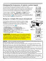
Temporarily muting the sound
MUTE button on the remote control.
1. Press
A dialog will appear on the screen indicating that you have
muted the sound.
To restore the sound, press the MUTE, VOLUME + or
VOLUME - button. Even if you do not do anything, the dialog
will automatically disappear after a few seconds.
VIDEO
ASPECT
MAGNIFY
MY SOURCE/
COMPUTER DOC.CAMERA
AUTO
FREEZE
SEARCH
BLANK
PAGE
UP
VOLUME
㧗
ON
OFF
KEYSTONE
DOWN
MY BUTTON
1
MUTE
2
● When is selected for current picture input port, the sound is always muted.
Please see AUDIO SOURCE item of AUDIO menu (42).
● C.C. (Closed Caption) is automatically activated when sound is muted and an
input signal containing C.C. is received. This function is available only when
the signal is NTSC for VIDEO or S-VIDEO, or 480i@60 for COMPONENT,
COMPUTER IN1 or COMPUTER IN2, and when AUTO is selected for
DISPLAY in the C.C. menu under the SCREEN menu (49).
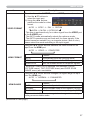
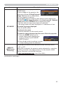
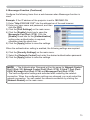
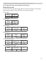
Selecting an input signal
INPUT button on the projector.
1. Press
Each time you press the button, the projector switches its
INPUT button
input port from the current port as below.
COMPUTER IN1 Æ COMPUTER IN2 Æ LAN
VIDEO
USB TYPE A
Æ
S-VIDEO
COMPONENT (Y, Cb/Pb, Cr/Pr)
USB TYPE B
HDMI
● While ON is selected for AUTO SEARCH item in OPTION menu (50), the
projector will keep checking the ports in above order repeatedly till an input
signal is detected.
● It may take several seconds to project the images from the USB TYPE B port.
(continued on next page)
18
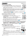
Operating
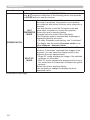
Selecting an input signal (continued)
Press COMPUTER button on the remote control.
1. Each
time you press the button, the projector switches its
COMPUTER button
input port from the current port as below.
COMPUTER IN1 Æ COMPUTER IN2 Æ LAN
USB TYPE B
USB TYPE A
● While ON is selected for AUTO SEARCH item in OPTION
menu, the projector will keep checking every port sequentially
till an input signal is detected (50). If COMPUTER button is
pressed when VIDEO, S-VIDEO, COMPONENT or HDMI port
is selected, the projector will check COMPUTER IN1 port rst.
● It may take several seconds to project the images from the
USB TYPE B port.
Æ
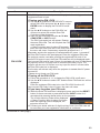
Press VIDEO button on the remote control.
1. Each
time you press the button, the projector switches its
VIDEO
ASPECT
MAGNIFY
AUTO
FREEZE
KEYSTONE
VOLUME
MY BUTTON
1
㧗
MUTE
2
MENU
POSITION
VIDEO button
ASPECT
MAGNIFY
MY SOURCE/
COMPUTER DOC.CAMERA
AUTO
FREEZE
SEARCH
BLANK
PAGE
UP
VOLUME
㧗
ON
DOWN
OFF
the MY SOURCE / DOC. CAMERA button on
1. Press
the remote control. The input signal will be changed
BLANK
PAGE
UP
DOWN
OFF
VIDEO
● While ON is selected for AUTO SEARCH item in OPTION
menu, the projector will keep checking every port sequentially
till an input signal is detected (50). If VIDEO button is
pressed when COMPUTER IN1 or COMPUTER IN2 port is
selected, the projector will check HDMI port rst.
SEARCH
ON
input port from the current port as below.
HDMI Æ COMPONENT (Y, Cb/Pb, Cr/Pr) Æ S-VIDEO
VIDEO
MY SOURCE/
COMPUTER DOC.CAMERA
KEYSTONE
MY BUTTON
1
MUTE
2
MENU
POSITION
MY SOURCE /
DOC. CAMERA button
into the signal you set as MY SOURCE (54).
● This function also can use for document camera. Select the
input port that connected the document camera.
VIDEO
ASPECT
MAGNIFY
MY SOURCE/
COMPUTER DOC.CAMERA
AUTO
FREEZE
SEARCH
BLANK
PAGE
UP
VOLUME
㧗
ON
OFF
KEYSTONE
POSITION
DOWN
MY BUTTON
1
MUTE
2
MENU
19
Operating
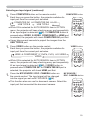
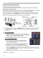
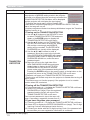
Searching an input signal
SEARCH button
SEARCH button on the remote control.
1. Press
The projector will start to check its input ports as below in
VIDEO
order to nd any input signals.
When an input is found, the projector will stop searching
and display the image. If no signal is found, the projector will
return to the state selected before the operation.
ASPECT
MAGNIFY
AUTO
FREEZE
SEARCH
BLANK
PAGE
UP
VOLUME
㧗
ON
DOWN
OFF
KEYSTONE
COMPUTER IN1 Æ COMPUTER IN2 Æ LAN
VIDEO
USB TYPE A
Æ
S-VIDEO
COMPONENT (Y, Cb/Pb, Cr/Pr)
MY SOURCE/
COMPUTER DOC.CAMERA
MY BUTTON
1
MUTE
2
MENU
POSITION
USB TYPE B
HDMI
● While ON is selected for AUTO SEARCH item in OPTION menu (50), the
projector will keep checking the ports in above order repeatedly till an input
signal is detected.
● It may take several seconds to project the images from the USB TYPE B port.
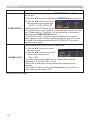
Selecting an aspect ratio
ASPECT button on the remote control.
1. Press
Each time you press the button, the projector switches the
ASPECT button
mode for aspect ratio in turn.
VIDEO
ASPECT
For a computer signal
NORMAL Æ 4:3 Æ 16:9 Æ 16:10
MAGNIFY
AUTO
FREEZE
SEARCH
BLANK
PAGE
UP
VOLUME
㧗
ON
OFF
KEYSTONE
For an HDMI signal
NORMAL Æ 4:3 Æ 16:9 Æ 16:10 Æ 14:9
MY SOURCE/
COMPUTER DOC.CAMERA
POSITION
DOWN
MY BUTTON
1
MUTE
2
MENU
For a video signal, s-video signal or component video signal
4:3 Æ 16:9 Æ 14:9
For an input signal from the LAN, USB TYPE A or USB TYPE B port, or
if there is no signal
4:3 (xed)
● ASPECT button does not work when no proper signal is inputted.
● NORMAL mode keeps the original aspect ratio setting.
20
Operating
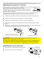
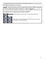
Adjusting the projector's elevator
When the place to put the projector is slightly uneven to the left or right, use the
elevator feet to place the projector horizontally.
Using the feet can also tilt the projector in order to project at
a suitable angle to the screen, elevating the front side of the 14°
projector within 14 degrees.
This projector has 2 elevator feet and 2 elevator buttons. An elevator foot is
adjustable while pushing the elevator button on the same side as it.
1. Holding the projector, push the elevator buttons to loose the elevator feet.
2. Position the front side of the projector to the desired height.
3. Release the elevator buttons in order to lock the elevator feet.
making sure that the elevator feet are locked, put the projector down
4. After
gently.
necessary, the elevator feet can be manually twisted to make more precise
5. Ifadjustments.
Hold the projector when twisting the feet.
1
To loose an elevator foot, push the
elevator button on the same side as it.
5
To nely adjust, twist the foot.
CAUTION ►Do not handle the elevator buttons without holding the
projector, since the projector may drop down.
►Do not tilt the projector other than elevating its front within 14 degrees using
the adjuster feet. A tilt of the projector exceeding the restriction could cause
malfunction or shortening the lifetime of consumables, or the projector itself.
Adjusting the zoom and focus
1. Use the zoom ring to adjust the screen size.
2. Use the focus ring to focus the picture.
Zoom ring
Focus ring
21
Operating
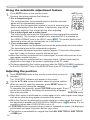
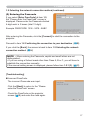
Using the automatic adjustment feature
AUTO button on the remote control.
1. Press
Pressing this button performs the following.
AUTO button
MY SOURCE/
COMPUTER DOC.CAMERA
For a computer signal
The vertical position, the horizontal position and the horizontal
phase will be automatically adjusted.
Make sure that the application window is set to its maximum size
prior to attempting to use this feature. A dark picture may still be
incorrectly adjusted. Use a bright picture when adjusting.
For a video signal and s-video signal
The video format best suited for the respective input signal will be selected
automatically. This function is available only when the AUTO is selected for
the VIDEO FORMAT item in the INPUT menu (37). The vertical position and
horizontal position will be automatically set to the default.
For a component video signal
The vertical position and horizontal position will be automatically set to the default.
The horizontal phase will be automatically adjusted.
● The automatic adjustment operation requires approx. 10 seconds. Also please
note that it may not function correctly with some input.
● When this function is performed for a video signal, a certain extra such as a line
may appear outside a picture.
● When this function is performed for a computer signal, a black frame may be
displayed on the edge of the screen, depending on the PC model.
● The items adjusted by this function may vary when the FINE or DISABLE is selected
for the AUTO ADJUST item of the SERVICE item in the OPTION menu (55).
VIDEO
ASPECT
MAGNIFY
AUTO
SEARCH
BLANK
PAGE
UP
VOLUME
FREEZE
㧗
ON
DOWN
OFF
KEYSTONE
MY BUTTON
1
MUTE
2
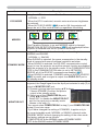
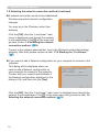
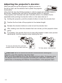
Adjusting the position
POSITION button on the remote control when no menu is
1. Press
indicated.
KEYSTONE
MY BUTTON
1
MUTE
2
The “POSITION” indication will appear on the screen.
Use the ▲/▼/◄/► cursor buttons to adjust the picture position.
When you want to reset the operation, press RESET button on
the remote control during the operation.
To complete this operation, press POSITION button again. Even if
you do not do anything, the dialog will automatically disappear
POSITION button
after a few seconds.
● When this function is performed on a video signal or an s-video signal, some image
such as an extra-line may appear at outside of the picture.
● When this function is performed on a video signal or s-video signal, the range of
this adjustment depends on OVER SCAN in IMAGE menu (33) setting. It is not
possible to adjust when OVER SCAN is set to 10.
● If POSITION button is pressed when a menu is indicated on screen, the displayed
picture does not move its position but the menu does.
● This function is unavailable for a signal from the LAN, USB TYPE A, USB TYPE B
or HDMI port.
MENU
POSITION
2.
22
ENTER
ESC
RESET
Operating
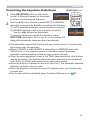
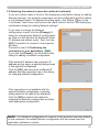
Correcting the keystone distortions
KEYSTONE button on the remote
1. Press
control. A dialog will appear on the screen
to aid you in correcting the distortion.
the ▲/▼ cursor buttons to select AUTO or MANUAL
2. Use
operation, and press the ► button to perform the following.
KEYSTONE button
VIDEO
ASPECT
MAGNIFY
MY SOURCE/
COMPUTER DOC.CAMERA
AUTO
FREEZE
SEARCH
BLANK
PAGE
UP
VOLUME
㧗
ON
OFF
KEYSTONE
DOWN
MY BUTTON
1
MUTE
2
(1) AUTO executes automatic vertical keystone correction.
(2) MANUAL displays a dialog for keystone correction.
Use the ◄/► buttons for adjustment.
To close the dialog and complete this operation, press
KEYSTONE button again. Even if you do not do anything, the
dialog will automatically disappear after a few seconds.
● The adjustable range of this function will vary among inputs. For some input,
this function may not work well.
● When V:INVERT or H&V:INVERT is selected to the MIRROR item in the
SETUP menu, if the projector screen is inclined or angled downward,
automatic vertical keystone correction may not work correctly.
● When the zoom adjustment is set to the TELE (telephoto focus), this function
may be excessive. This function should be used when the zoom adjustment
is set to the full WIDE (wide-angle focus) whenever possible.
● When the projector is placed on the level (about ±4°), the automatic keystone
distortion correction may not work.
● When the projector is inclined to near ±30 degree or over, this function may
not work well.
● This function will be unavailable when Transition Detector is on (70).
23
Operating
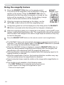
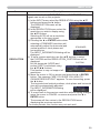
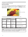
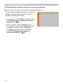
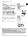
Using the magnify feature
the MAGNIFY ON button on the remote control.
1. Press
The picture will be magnied, and the MAGNIFY dialog will
appear on the screen. When the MAGNIFY ON button is
pressed for the rst time after the projector is turned on, the
picture will be zoomed by 1.5 times. On the dialog, triangle
marks to show each direction will be displayed.
MAGNIFY
ON/OFF button
VIDEO
ASPECT
MAGNIFY
2.
AUTO
FREEZE
SEARCH
BLANK
PAGE
UP
VOLUME
㧗
ON
OFF
While the triangles are displayed on the dialog, use the
▲/▼/◄/► cursor buttons to shift the magnifying area.
MY SOURCE/
COMPUTER DOC.CAMERA
KEYSTONE
DOWN
MY BUTTON
1
MUTE
2
glass icon will be displayed on the dialog when the MAGNIFY
3. AONmagnifying
button is pressed while the dialog with the triangles is displayed.
While the magnifying glass icon is displayed on the dialog, use the ▲/▼ cursor
4. buttons
to adjust the magnication ratio. The magnication ratio will be adjusted
with ne steps. And changes in the ratio in single steps are subtle so they may
be hard to recognize.
5. Press the MAGNIFY OFF button on the remote control to exit magnication.
● The MAGNIFY dialog will automatically disappear in several seconds with no
operation. The dialog will appear again if the MAGNIFY ON button is pressed
when the dialog has automatically disappeared.
● While the MAGNIFY dialog is displayed, press the MAGNIFY ON button to
switch the dialog between magnifying area shifting (with the triangles) and
magnication ratio adjustment (with the magnifying glass icon).
● The magnication is automatically disabled when the displaying signal or its
display condition is changed.
● While the magnication is active, the keystone distortion condition may vary.
It will be restored when the magnication is disabled.
● Some horizontal stripes might be visible on the image while magnication is
active.
● This function is not available in the following cases:
- The USB TYPE A port is selected as the input source.
- A sync signal in the range not supported is input.
- There is no input signal.
24
Operating
Temporarily freezing the screen
1.
Press the FREEZE button on the remote control.
The “FREEZE” indication will appear on the screen (however,
the indication will not appear when the OFF is selected for
the MESSAGE item in the SCREEN menu (46)), and the
projector will go into the FREEZE mode, which the picture is
frozen.
To exit the FREEZE mode and restore the screen to normal,
press the FREEZE button again.
FREEZE button
VIDEO
ASPECT
MAGNIFY
MY SOURCE/
COMPUTER DOC.CAMERA
AUTO
FREEZE
SEARCH
BLANK
PAGE
UP
VOLUME
㧗
ON
DOWN
OFF
KEYSTONE
MY BUTTON
1
MUTE
2
● The projector automatically exits from the FREEZE mode when some control
buttons are pressed.
● If the projector continues projecting a still image for a long time, the LCD
panel might possibly be burned in. Do not leave the projector in the FREEZE
mode for too long.
● Images might appear degraded when this function is operated, but it is not a
malfunction.
Temporarily blanking the screen
Press BLANK button on the remote control.
1. The
BLANK screen will be displayed instead of the screen of
input signal. Please refer to BLANK item in SCREEN menu
(44).
To exit from the BLANK screen and return to the input signal
screen, press BLANK button again.
BLANK button
VIDEO
ASPECT
MAGNIFY
MY SOURCE/
COMPUTER DOC.CAMERA
AUTO
FREEZE
SEARCH
BLANK
PAGE
UP
VOLUME
㧗
ON
OFF
KEYSTONE
DOWN
MY BUTTON
1
MUTE
2
● The projector automatically exits from the BLANK mode when
some control buttons are pressed.
CAUTION ►If you wish to have a blank screen while the projector's lamp
is on, use one of methods below.
- Use the supplied lens cover.
- Use the BLANK function above.
Taking any other action may cause the damage on the projector.
NOTE • The sound is not connected with the BLANK screen function. If
necessary, set the volume or mute rst. To display the BLANK screen and mute
the sound at one time, use AV MUTE function (53).
25
Operating
Using the menu function
This projector has the following menus:
PICTURE, IMAGE, INPUT, SETUP, AUDIO, SCREEN, OPTION, NETWORK,
SECURITY and EASY MENU.
EASY MENU consists of functions often used, and the other menus are classied
into each purpose and brought together as the ADVANCED MENU.
Each of these menus is operated using the same methods. While the projector
is displaying any menu, the MENU button on the projector works as the cursor
buttons. The basic operations of these menus are as follows.
ENTER button
MENU button
Cursor buttons
MENU
POSITION
VIDEO
ASPECT
MAGNIFY
MY SOURCE/
COMPUTER DOC.CAMERA
AUTO
FREEZE
SEARCH
BLANK
PAGE
UP
VOLUME
㧗
ON
DOWN
OFF
ENTER
MENU button
(Cursor buttons)
KEYSTONE
MY BUTTON
1
MUTE
2
MENU
POSITION
ENTER
RESET
ESC
ESC button
ESC
RESET
RESET button
start the MENU, press the MENU button. The MENU you last used (EASY
1. To
or ADVANCED) will appear. EASY MENU has priority to appear just after
powered on.
EASY MENU
2. In(1)the
Use the ▲/▼ cursor buttons to select an item to
operate. If you want to change it to the ADVANCED
MENU, select the ADVANCED MENU.
(2) Use the ◄/► cursor buttons to operate the item.
In the ADVANCED MENU
(1) Use the ▲/▼ cursor buttons to select a menu.
If you want to change it to the EASY MENU,
select the EASY MENU.
The items in the menu appear on the right side.
(2) Press the ► cursor button or ENTER button to
move the cursor to the right side. Then use the
▲/▼ cursor buttons to select an item to operate and press the ► cursor
button or ENTER button to progress. The operation menu or dialog of the
selected item will appear.
(3) Use the buttons as instructed in the OSD to operate the item.
(continued on next page)
26
Operating
Using the menu function (continued)
close the MENU, press the MENU button again or select EXIT and press
3. To
the ◄ cursor button or ENTER button. Even if you do not do anything, the
dialog will automatically disappear after about 30 seconds.
● If you want to move the menu position, use the cursor buttons after pressing the
POSITION button.
● Some functions cannot be performed when a certain input port is selected, or
when a certain input signal is displayed.
● When you want to reset the operation, press RESET button on the remote
control during the operation. Note that some items (ex. LANGUAGE, VOLUME)
cannot be reset.
● In the ADVANCED MENU, when you want to return to the previous display,
press the ◄ cursor button or ESC button on the remote control.
Indication in OSD (On Screen Display)
The meanings of the general words on the OSD are as follows.
Indication
Meaning
EXIT
Selecting this word nishes the OSD menu. It's the same as
pressing the MENU button.
RETURN
Selecting this word returns the menu to the previous menu.
CANCEL or NO
OK or YES
Selecting this word cancels the operation in the present
menu and returns to the previous menu.
Selecting this word executes the prepared function or shifts
the menu to the next menu.
27
EASY MENU
EASY MENU
From the EASY MENU, items shown in the table
below can be performed.
Select an item using the ▲/▼ cursor buttons. Then
perform it according to the following table.
Item
ASPECT
AUTO KEYSTONE
KEYSTONE
Description
Using the ◄/► buttons switches the mode for aspect ratio.
See the ASPECT item in IMAGE menu (33).
Using the ► button executes the auto keystone function.
See the AUTO KEYSTONE (EXECUTE) item in SETUP menu (40).
Using the ◄/► buttons corrects the vertical keystone distortion.
See the KEYSTONE item in SETUP menu (40).
Using the ◄/► buttons switches the picture mode.
The picture modes are combinations of GAMMA and COLOR TEMP
settings. Choose a suitable mode according to the projected source.
NORMAL Ù CINEMA Ù DYNAMIC Ù BOARD(BLACK)
DAYTIME Ù WHITEBOARD Ù BOARD(GREEN)
PICTURE MODE
NORMAL
CINEMA
DYNAMIC
BOARD(BLACK)
BOARD(GREEN)
WHITEBOARD
DAYTIME
GAMMA
1 DEFAULT
2 DEFAULT
3 DEFAULT
4 DEFAULT
4 DEFAULT
5 DEFAULT
6 DEFAULT
COLOR TEMP
2 MID
3 LOW
1 HIGH
4 Hi-BRIGHT-1
5 Hi-BRIGHT-2
2 MID
6 Hi-BRIGHT-3
• When the combination of GAMMA and COLOR TEMP differs
from pre-assigned modes above, the display on the menu for the
PICTURE MODE is “CUSTOM”. Please refer to the GAMMA and
COLOR TEMP (30, 31) items in PICTURE menu.
• Lines or other noise might appear on the screen when this function
is operated, but it is not a malfunction.
(continued on next page)
28
EASY MENU
Item
ECO MODE
MIRROR
Description
Using the ◄/► buttons turns off/on the Eco mode.
See the ECO MODE item in SETUP menu (41).
Using the ◄/► buttons switches the mode for mirror status.
See the MIRROR item in SETUP menu (41).
RESET
Performing this item resets all of the EASY MENU items except the
FILTER TIME and LANGUAGE.
A dialog is displayed for conrmation. Selecting the OK using the ►
button performs resetting.
FILTER TIME
The usage time of the air lter is shown in the menu.
Performing this item resets the lter time which counts usage time
of the air lter.
A dialog is displayed for conrmation. Selecting the OK using the ►
button performs resetting.
See the FILTER TIME item in OPTION menu (52).
LANGUAGE
Using the ◄/► buttons changes the display language.
See the LANGUAGE item in SCREEN menu (44).
Press the ► or ENTER button to use the menu of PICTURE,
ADVANCED MENU IMAGE, INPUT, SETUP, AUDIO, SCREEN, OPTION, NETWORK or
SECURITY.
EXIT
Press the ◄ or ENTER button to nish the OSD menu.
29
PICTURE menu
PICTURE menu
From the PICTURE menu, items shown in the table
below can be performed.
Select an item using the ▲/▼ cursor buttons, and press
the ► cursor button or ENTER button to execute the
item. Then perform it according to the following table.
Item
BRIGHTNESS
CONTRAST
Description
Using the ◄/► buttons adjusts the brightness.
Dark Ù Light
Using the ◄/► buttons adjusts the contrast.
Weak Ù Strong
Using the ▲/▼ buttons switches the gamma mode.
Ù
Ù
6 CUSTOM
3 CUSTOM
Ù
Ù
1 DEFAULT Ù 1 CUSTOM Ù 2 DEFAULT Ù 2 CUSTOM Ù 3 DEFAULT
6 DEFAULT Ù 5 CUSTOM Ù 5 DEFAULT Ù 4 CUSTOM Ù 4 DEFAULT
To adjust CUSTOM
GAMMA
Selecting a mode whose name includes CUSTOM and then
pressing the ► button or the ENTER button displays
a dialog to aid you in adjusting the mode.
This function is useful when you want to
change the brightness of particular tones.
Choose an item using the ◄/► buttons,
and adjust the level using the ▲/▼ buttons.
You can display a test pattern for checking the effect of your
adjustment by pressing the ENTER button.
Each time you press the ENTER button, the
pattern changes as below.
No pattern Ö Gray scale of 9 steps
Ramp Õ Gray scale of 15 steps
The eight equalizing bars correspond to eight tone levels of the test
pattern (Gray scale of 9 steps) except the darkest in the left end. If you
want to adjust the 2nd tone from left end on the test pattern, use the
equalizing adjustment bar “1”. The darkest tone at the left end of the
test pattern cannot be controlled with any of equalizing adjustment bar.
• Lines or other noise might appear on the
screen when this function is operated, but it
is not a malfunction.
(continued on next page)
30
PICTURE menu
Item
Description
Using the ▲/▼ buttons switches the color temperature mode.
3 LOW
6 Hi-BRIGHT-3
3 CUSTOM
Ù
Ù
Ù
6 CUSTOM
Ù
Ù
2 CUSTOM
Ù
1 HIGH Ù 1 CUSTOM Ù 2 MID Ù
5 CUSTOM Ù 5 Hi-BRIGHT-2 Ù 4 CUSTOM Ù 4 Hi-BRIGHT-1
To adjust CUSTOM
COLOR TEMP
Selecting a mode whose name includes
CUSTOM and then pressing the ► button
or the ENTER button displays a dialog
to aid you in adjusting the OFFSET and
GAIN of the selected mode.
OFFSET adjustments change the color intensity on the whole tones
of the test pattern.
GAIN adjustments mainly affect color intensity on the brighter tones
of the test pattern.
Choose an item using the ◄/► buttons, and adjust the level using
the ▲/▼ buttons.
You can display a test pattern for checking the effect of your
adjustment by pressing the ENTER button.
Each time you press the ENTER button, the pattern changes as below.
No pattern Ö Gray scale of 9 steps
Ramp Õ Gray scale of 15 steps
• Lines or other noise might appear on the screen
when this function is operated, but it is not a
malfunction.
COLOR
Using the ◄/► buttons adjusts the strength of whole color.
Weak Ù Strong
• This item can be selected only for a video, s-video and component
video signal.
• For an HDMI signal, this item can also be selected if either (1) or (2) applies.
(1) HDMI FORMAT item in the INPUT menu is set to VIDEO.
(2) HDMI FORMAT item in the INPUT menu is set to AUTO, and the
projector recognizes that it receives video signals.
TINT
Using the ◄/► buttons adjusts the tint.
Reddish Ù Greenish
• This item can be selected only for a video, s-video and component
video signal.
• For an HDMI signal, this item can also be selected if either (1) or (2) applies.
(1) HDMI FORMAT item in the INPUT menu is set to VIDEO.
(2) HDMI FORMAT item in the INPUT menu is set to AUTO, and the
projector recognizes that it receives video signals.
(continued on next page)
31
PICTURE menu
Item
SHARPNESS
Description
Using the ◄/► buttons adjusts the sharpness.
Weak Ù Strong
• There may be some noise and/or the screen may icker for a
moment when an adjustment is made. This is not a malfunction.
This item is available only for CP-X2511N, CP-X3011N or CP-X4011N.
Using the ▲/▼ cursor buttons changes the active iris control mode.
PRESENTATION Ù THEATER Ù OFF
ACTIVE IRIS
MY MEMORY
32
PRESENTATION : The active iris displays the best presentation
image for both bright and dark scenes.
THEATER : The active iris displays the best theater image for
both bright and dark scenes.
OFF : The active iris is always open.
• The screen may icker when the PRESENTATION or THEATER
modes are selected. If this occurs select OFF.
This projector has 4 memories for adjustment data (for all the items
of the PICTURE menu).
Selecting a function using the ▲/▼ buttons and pressing the ► or
ENTER button performs each function.
SAVE-1 Ù SAVE-2 Ù SAVE-3 Ù SAVE-4
LOAD-4 ÙLOAD-3 Ù LOAD-2 Ù LOAD-1
SAVE-1, SAVE-2, SAVE-3, SAVE-4
Performing a SAVE function saves the current adjustment data into
the memory linked in the number included in the function’s name.
• Remember that the current data being stored of a memory will be
lost by saving new data into the memory.
LOAD-1, LOAD-2, LOAD-3, LOAD-4
Performing a LOAD function loads the data from the memory linked
in the number included in the function’s name, and adjusts the
picture automatically depending on the data.
• The LOAD functions whose linked memory has no data are
skipped.
• Remember that the current adjusted condition will be lost by
loading data. If you want to keep the current adjustment, please
save it before performing a LOAD function.
• There may be some noise and the screen may icker for a
moment when loading data. This is not malfunction.
• You can perform the LOAD function using MY BUTTON. Please
see MY BUTTON item in OPTION menu (53).
IMAGE menu
IMAGE menu
From the IMAGE menu, items shown in the table
below can be performed.
Select an item using the ▲/▼ cursor buttons, and
press the ► cursor button or ENTER button to
execute the item. Then perform it according to the
following table.
Item
Description
Using the ▲/▼ buttons switches the mode for aspect ratio.
For a computer signal
NORMAL Ù 4:3 Ù 16:9 Ù 16:10
For an HDMI signal
NORMAL Ù 4:3 Ù 16:9 Ù 16:10 Ù 14:9
ASPECT
For a video signal, s-video signal or component video signal
4:3 Ù 16:9 Ù 14:9
For an input signal from the LAN, USB TYPE A or USB TYPE B
port, or if there is no signal
4:3 (xed)
• The NORMAL mode keeps the original aspect ratio of the signal.
OVER SCAN
Using the ◄/► buttons adjusts the over-scan ratio.
Small (It magnies picture) Ù Large (It reduces picture)
• This item can be selected only for a video, s-video and component
video signal.
• For an HDMI signal, this item can also be selected if either (1) or (2)
applies.
(1) HDMI FORMAT item in the INPUT menu is set to VIDEO.
(2) HDMI FORMAT item in the INPUT menu is set to AUTO, and the
projector recognizes that it receives video signals.
• When this adjustment is too large, certain degradation may appear
at the frame area of the picture. In such a case, please adjust small.
(continued on next page)
33
IMAGE menu
Item
Description
V POSITION
Using the ◄/► buttons adjusts the vertical position.
Down Ù Up
• Over-adjusting the vertical position may cause noise to appear on
the screen. If this occurs, please reset the vertical position to the
default setting. Pressing the RESET button when the V POSITION
is selected will reset the V POSITION to the default setting.
• When this function is performed on a video signal or an s-video
signal, the range of this adjustment depends on OVER SCAN (33)
setting. It is not possible to adjust when OVER SCAN is set to 10.
• This function is unavailable for a signal from the LAN, USB TYPE A,
USB TYPE B or HDMI port.
H POSITION
Using the ◄/► buttons adjusts the horizontal position.
Right Ù Left
• Over-adjusting the horizontal position may cause noise to appear on
the screen. If this occurs, please reset the horizontal position to the
default setting. Pressing the RESET button when the H POSITION is
selected will reset the H POSITION to the default setting.
• When this function is performed on a video signal or an s-video
signal, the range of this adjustment depends on OVER SCAN (33)
setting. It is not possible to adjust when OVER SCAN is set to 10.
• This function is unavailable for a signal from the LAN, USB TYPE A,
USB TYPE B or HDMI port.
(continued on next page)
34
IMAGE menu
Item
Description
H PHASE
Using the ◄/► buttons adjusts the horizontal phase to eliminate icker.
Right Ù Left
• This item can be selected only for a computer signal or a
component video signal. This function is unavailable for a signal
from the LAN, USB TYPE A, USB TYPE B or HDMI port.
H SIZE
Using the ◄/► buttons adjusts the horizontal size.
Small Ù Large
• This item can be selected only for a computer signal. This function
is unavailable for a signal from the LAN, USB TYPE A, USB TYPE
B or HDMI port.
• When this adjustment is excessive, the picture may not be
displayed correctly. In such a case, please reset the adjustment
by pressing the RESET button on the remote control during this
operation.
• Images might appear degraded when this function is operated, but
it is not a malfunction.
Selecting this item performs the automatic adjustment feature.
For a computer signal
The vertical position, the horizontal position and the horizontal
phase will be automatically adjusted.
Make sure that the application window is set to its maximum size
prior to attempting to use this feature. A dark picture may still be
incorrectly adjusted. Use a bright picture when adjusting.
For a video signal and s-video signal
The video format best suited for the respective input signal will
be selected automatically. This function is available only when
the AUTO is selected for the VIDEO FORMAT item in the INPUT
menu (37). The vertical position and horizontal position will be
AUTO ADJUST
EXECUTE
automatically set to the default.
For a component video signal
The vertical position and horizontal position will be automatically
set to the default. The horizontal phase will be automatically
adjusted.
• The automatic adjustment operation requires approx. 10 seconds.
Also please note that it may not function correctly with some input.
• When this function is performed for a video signal, a certain extra
such as a line may appear outside a picture.
• When this function is performed for a computer signal, a black
frame may be displayed on the edge of the screen, depending on
the PC model.
• The items adjusted by this function may vary when the FINE or
DISABLE is selected for the AUTO ADJUST item of the SERVICE
item in the OPTION menu (55).
35
INPUT menu
INPUT menu
From the INPUT menu, items shown in the table
below can be performed.
Select an item using the ▲/▼ cursor buttons, and
press the ► cursor button or ENTER button to
execute the item. Then perform it according to the
following table.
Item
Description
Using the ▲/▼ buttons switches the progress mode.
TV Ù FILM Ù OFF
PROGRESSIVE
• This function works only for a video signal, s-video signal, component
video signal (of 480i@60 or 576i@50 or 1080i@50/60) and an HDMI
signal (of 480i@60 or 576i@50 or 1080i@50/60).
• When TV or FILM is selected, the screen image will be sharp.
FILM adapts to the 2-3 Pull-Down conversion system. But these
may cause a certain defect (for example, jagged line) of the picture
for a quick moving object. In such a case, please select OFF, even
though the screen image may lose sharpness.
Using the ▲/▼ buttons switches the noise reduction mode.
HIGH Ù MID Ù LOW
VIDEO NR
• This function works only for a video signal, s-video signal, component video signal (of 480i@60 or 576i@50 or 1080i@50/60) and an
HDMI signal (of 480i@60 or 576i@50 or 1080i@50/60).
• When this function is excessive, it may cause a certain
degradation of the picture.
Using the ▲/▼ buttons switches the mode for color space.
AUTO Ù RGB Ù SMPTE240 Ù REC709 Ù REC601
COLOR SPACE
COMPONENT
• This item can be selected only for a computer signal (except for
signals from the LAN, USB TYPE A and USB TYPE B ports) or a
component video signal (except SCART RGB).
• The AUTO mode automatically selects the optimum mode.
• The AUTO operation may not work well at some signals. In such a
case, it might be good to select a suitable mode except AUTO.
Using the ▲/▼ buttons switches the function of the COMPONENT
(Y, Cb/Pb, Cr/Pr) port.
COMPONENT Ù SCART RGB
When the SCART RGB is selected, the COMPONENT (Y, Cb/
Pb, Cr/Pr) and VIDEO ports will function as a SCART RGB port.
A SCART adapter or SCART cable is required for a SCART RGB
input to the projector. For details, contact your dealer.
(continued on next page)
36
INPUT menu
Item
Description
VIDEO FORMAT
The video format for S-VIDEO port and VIDEO port can be set.
(1) Use the ▲/▼ buttons to
select the input port.
(2) Using the ◄/► buttons
switches the mode for video
format.
AUTO Ù NTSC Ù PAL Ù SECAM
N-PAL Ù M-PAL Ù NTSC4.43
• This item is performed only for a video signal from the VIDEO port
or the S-VIDEO port.
• The AUTO mode automatically selects the optimum mode.
• The AUTO operation may not work well for some signals. If the
picture becomes unstable (e.g. an irregular picture, lack of color),
please select the mode according to the input signal.
Using the ▲/▼ cursor buttons switches the video format for an
input from the HDMI port.
AUTO Ù VIDEO Ù COMPUTER
HDMI FORMAT
AUTO
VIDEO
COMPUTER
Feature
automatically sets the optimum mode.
sets the suitable mode for DVD signals.
sets the suitable mode for computer signals.
• When the COMPUTER is selected, the functions COLOR
(PICTURE menu), TINT (PICTURE menu) and OVER SCAN
(IMAGE menu) are unavailable.
Using the ▲/▼ cursor buttons changes the digital range for input
from the HDMI port.
AUTO Ù NORMAL Ù ENHANCED
HDMI RANGE
AUTO
NORMAL
ENHANCED
Feature
automatically sets the optimum mode.
sets the suitable mode for DVD signals. (16-235)
sets the suitable mode for computer signals. (0-255)
• If the contrast of the screen image is too strong or too weak, try
nding a more suitable mode.
(continued on next page)
37
INPUT menu
Item
Description
COMPUTER IN
The computer input signal type for COMPUTER IN1 and IN2 ports
can be set.
(1) Use the ▲/▼ buttons to select the COMPUTER IN port to be set.
(2) Use the ◄/► buttons to select
the computer input signal type.
AUTO Ù SYNC ON G OFF
• Selecting the AUTO mode allows
you to input a sync on G signal or component video signal from the
port. Please refer to “Technical” for the connection of component
video input to COMPUTER IN1/2 port.
• In the AUTO mode, the picture may be distorted with certain
input signals. In such a case, remove the signal connector so that
no signal is received and select the SYNC ON G OFF, and then
reconnect the signal.
FRAME LOCK
Set the frame lock function on/off for each port.
(1) Use the ▲/▼ buttons to select
the input ports.
(2) Use the ◄/► buttons to turn the
frame lock function on/off .
ON Ù OFF
• This item can be performed only on a signal with a vertical
frequency of 49 to 51Hz, 59 to 61 Hz.
• When ON is selected, moving pictures are displayed more
smoothly.
• This function may cause a certain degradation of the picture. In
such a case, please select OFF.
(continued on next page)
38
INPUT menu
Item
Description
RESOLUTION
The resolution for the COMPUTER IN1 and COMPUTER IN2 input
signals can be set on this projector.
(1) In the INPUT menu select the RESOLUTION using the ▲/▼
buttons and press the ► button.
The RESOLUTION menu will be
displayed.
(2) In the RESOLUTION menu select the
resolution you wish to display using
the ▲/▼ buttons.
Selecting AUTO will set a resolution
appropriate to the input signal.
(3) Pressing the ► or ENTER button when
selecting a STANDARD resolution will
automatically adjust the horizontal and
STANDARD
vertical positions, clock phase and
↓
horizontal size.
The INPUT_INFORMATION dialog will be
displayed.
(4) To set a custom resolution use the ▲/▼ buttons to select
the CUSTOM and the RESOLUTION_CUSTOM box will be
displayed.
CUSTOM
Set the horizontal (HORZ) and
↓
vertical (VERT) resolutions using
the ▲/▼/◄/► buttons.
This function is may not support all
resolutions.
(5) Move the cursor to OK on screen and press the ► or ENTER
button. The message "ARE YOU SURE YOU WISH TO
CHANGE RESOLUTION?" appears. To save the setting, press
the ► button.
The horizontal and vertical positions, clock phase and horizontal
size will be automatically adjusted.
The INPUT_INFORMATION dialog
will be displayed.
(6) To revert back to the previous resolution without saving changes,
move the cursor to CANCEL on screen and press the ◄ or
ENTER button.
The screen will then return to the RESOLUTION menu
displaying the previous resolution.
• For some pictures, this function may not work well.
39
SETUP menu
SETUP menu
From the SETUP menu, items shown in the table
below can be performed.
Select an item using the ▲/▼ cursor buttons, and
press the ► cursor button or ENTER button to
execute the item. Then perform it according to the
following table.
Item
Description
Selecting this item performs the Automatic keystone distortion
correction. Projector automatically corrects vertical keystone
distortion due to the (forward/backward) setup angle by itself.
This function will be executed only once when selected in the menu.
When the slant of the projector is changed, execute this function again.
• The adjustable range of this function will vary among inputs. For
some input, this function may not work well.
• When V:INVERT or H&V:INVERT is selected to the MIRROR item
in the SETUP menu, if the projector screen is inclined or angled
AUTO KEYSTONE downward, this function may not work correctly.
• When the zoom adjustment is set to the TELE (telephoto focus),
this function may be excessive. This function should be used when
the zoom adjustment is set to the full WIDE (wide-angle focus)
whenever possible.
• When the projector is placed on the level (about ±4°), this function
may not work.
• When the projector is inclined to near ±30 degree or over, this
function may not work well.
• This function will be unavailable when the Transition Detector is on
(70).
KEYSTONE
Using the ◄/► buttons corrects the vertical keystone distortion.
Shrink the bottom of the image Ù Shrink the top of the image
• The adjustable range of this function will vary among inputs. For
some input, this function may not work well.
• When the zoom adjustment is set to the TELE (telephoto focus),
this function may be excessive. This function should be used when
the zoom adjustment is set to the full WIDE (wide-angle focus)
whenever possible.
• This function will be unavailable when the Transition Detector is on
(70).
Using the ▲/▼ buttons turns on/off the AUTO ECO MODE.
ON Ù OFF
When
ON is selected, the projector will always be set to Eco mode
•
AUTO ECO MODE
at start-up regardless of the ECO MODE (41) setting. An OSD
message “AUTO ECO MODE” will be displayed for tens of seconds
when the projector starts with this function activated.
(continued on next page)
40
SETUP menu
Item
ECO MODE
Description
Using the ▲/▼ buttons turns off/on the Eco mode.
NORMAL Ù ECO
• When the ECO is selected, acoustic noise and screen brightness
are reduced.
• When AUTO ECO MODE (40) is set to ON, the projector will
always be set to Eco mode at start-up regardless this setting.
Using the ▲/▼ buttons switches the mode for mirror status.
MIRROR
NORMAL Ù H:INVERT Ù V:INVERT Ù H&V:INVERT
If the Transition Detector is on and MIRROR status is changed,
TRANSITION DETECTOR ON alarm (70) will be displayed when
projector is restarted after the AC power is turned off.
STANDBY MODE
Using ▲/▼ buttons switches the standby mode setting between
NORMAL and SAVING.
NORMAL Ù SAVING
When SAVING is selected, the power consumption in the standby
mode is lowered with some functional restriction as below:
• When SAVING is selected, the RS-232C communication control
except to turn the projector on and the network function are disabled
while the projector is in the standby mode. If the COMMUNICATION
TYPE in the COMMUNICATION menu is set to NETWORK
BRIDGE, all of the RS-232C commands are disabled (57).
• When SAVING is selected, STANDBY setting of AUDIO SOURCE
(42) is invalid, and no signal is output from AUDIO OUT port in
the standby mode.
MONITOR OUT
While the image signal from the input port chosen in step (1) is
projected, the image signal from the input port selected in step (2) is
output to MONITOR OUT port.
(1) Choose a picture input port using ▲/▼ buttons.
Choose STANDBY to select the picture
output in the standby mode.
(2) Select one of the COMPUTER IN ports
using ◄/► buttons.
Select OFF to disable the MONITOR OUT
port for the input port or standby mode
chosen in the step (1).
• You cannot select COMPUTER IN1 in step (1) and COMPUTER IN2
in step (2) and vice versa.
• If you have changed the setting of STANDBY, it applies only to
the current standby mode, NORMAL or SAVING, selected under
STANDBY MODE, without changing the setting of the other mode.
The factory settings are as follows:
- COMPUTER IN1 for the NORMAL mode of STANDBY MODE
- OFF for the SAVING mode of STANDBY MODE
41
AUDIO menu
AUDIO menu
From the AUDIO menu, items shown in the table below
can be performed. Select an item using the ▲/▼ cursor
buttons, and press the ► cursor button or the ENTER
button to execute the item. Then perform it according to
the following table.
Item
Description
VOLUME
Using the ◄/► buttons adjusts the volume.
Low Ù High
SPEAKER
Using the ▲/▼ buttons turns on/off the built-in speaker.
ON Ù OFF
When OFF is selected, the built-in speaker does not work.
AUDIO SOURCE
While the image signal from the input port chosen in step (1) is
projected, the audio signal from the input port selected in step
(2) is output to both the AUDIO OUT port and built-in speaker of
this projector. However, the built-in speaker does not work when
SPEAKER is set to OFF.
(1) Choose a picture input port using the
▲/▼ buttons.
Choose STANDBY to select the sound
output in the standby mode.
(2) Select one of the AUDIO IN ports using
◄/► buttons.
Select to mute the sound from the
input port or in the standby mode chosen in the step (1).
• In the AUDIO SOURCE window, “H” symbolizes the audio signal
from the HDMI port. It can be selected only for the picture input from
the HDMI port.
• Even if the projector is in the standby mode, cooling fans may
work and make noises when the built-in speaker is in operation.
• C.C. (Closed Caption) is automatically activated when is selected
and an input signal containing C.C. is received. This function is
available only when the signal is NTSC for VIDEO or S-VIDEO, or
480i@60 for COMPONENT, COMPUTER IN1 or COMPUTER IN2,
and when AUTO is selected for DISPLAY in the C.C. menu under the
SCREEN menu (49).
(continued on next page)
42
AUDIO menu
Item
Description
HDMI AUDIO
Using the ▲/▼ buttons switches the mode for the HDMI audio.
Check each of the two modes provided and select the suitable one
for your HDMI audio device.
1Ù2
MIC LEVEL
Using the ▲/▼ buttons switches the input level to match that of the
microphone connected to the MIC port.
HIGH Ù LOW
HIGH: for a microphone with an amplier.
LOW: for a microphone without an amplier.
MIC VOLUME
Using the ◄/► buttons adjusts the volume of the microphone
connected to the MIC port.
Low Ù High
43
SCREEN menu
SCREEN menu
From the SCREEN menu, items shown in the table
below can be performed.
Select an item using the ▲/▼ cursor buttons, and
press the ► cursor button or ENTER button to
execute the item. Then perform it according to the
following table.
Item
LANGUAGE
Description
Using the ▲/▼/◄/► buttons switches the OSD (On Screen
Display) language.
ENGLISH Ù FRANÇAIS Ù DEUTSCH Ù ESPAÑOL
(shown in the LANGUAGE dialog)
Press the ENTER or INPUT button to save the language setting.
MENU POSITION
Using the ▲/▼/◄/► buttons adjusts the menu position.
To quit the operation, press the MENU button on the remote control
or keep no operation for about 10 seconds.
Using the ▲/▼ buttons switches the mode for the blank screen.
The blank screen is a screen for the temporarily blanking feature
(25). It is displayed by pressing the BLANK button on the remote
control.
MyScreen Ù ORIGINAL Ù BLUE Ù WHITE Ù BLACK
BLANK
MyScreen : Screen can be registered by the MyScreen item (45).
ORIGINAL : Screen preset as the standard screen.
BLUE, WHITE, BLACK : Plain screens in each color.
• To avoid remaining as an afterimage, the MyScreen or ORIGINAL
screen will change to the plain black screen after several minutes.
Using the ▲/▼ buttons switches the mode for the start-up screen.
The start-up screen is a screen displayed when no signal or an
unsuitable signal is detected.
MyScreen Ù ORIGINAL Ù OFF
START UP
MyScreen : Screen can be registered by the MyScreen item (45).
ORIGINAL : Screen preset as the standard screen.
OFF : Plain black screen.
• To avoid remaining as an afterimage, the MyScreen or ORIGINAL
screen will change to the BLANK screen (above) after several
minutes. If also the BLANK screen is the MyScreen or ORIGINAL,
the plain black screen is instead used.
• When the ON is selected to the MyScreen PASSWORD item in
the SECURITY menu (68), the START UP is fixed to MyScreen.
(continued on next page)
44
SCREEN menu
Item
Description
MyScreen
This item allows you to capture an image for use as a MyScreen
image which can be used as the BLANK screen and START UP
screen. Display the image you want to capture before executing the
following procedure.
1. Selecting this item displays a dialog
titled “MyScreen”. It will ask you if
you start capturing an image from
the current screen.
Please wait for the target image to be displayed, and press the
ENTER or INPUT button when the image is displayed. The image
will freeze and the frame for capturing will appear.
To stop performing, press the RESET button on the remote
control.
2. Using the ▲/▼/◄/► buttons adjusts the
frame position.
Please move the frame to the position
of the image which you want to use. The
frame may not be able to be moved for
some input signals.
To start registration, press the ENTER
or INPUT button on the remote control.
To restore the screen and return to the previous dialog, press the
RESET button on the remote control.
Registration takes several minutes.
When the registration is completed, the registered screen and the
following message is displayed for several seconds:
“MyScreen registration is nished.”
If the registration failed, the following message is displayed:
“A capturing error has occurred. Please try again.”
• This function cannot be selected when the ON is selected to the
MyScreen Lock item (46).
• This function cannot be selected when the ON is selected to the
MyScreen PASSWORD item in SECURITY menu (68).
• This function is unavailable for a signal from the LAN, USB TYPE A,
USB TYPE B or HDMI port.
(continued on next page)
45
SCREEN menu
Item
Description
MyScreen Lock
Using the ▲/▼ buttons turns on/off the MyScreen lock function.
ON Ù OFF
When the ON is selected, the item MyScreen is locked. Use this
function for protecting the current MyScreen.
• This function cannot be selected when the ON is selected to the
MyScreen PASSWORD item in SECURITY menu (68).
MESSAGE
Using the ▲/▼ buttons turns on/off the message function.
ON Ù OFF
When the ON is selected, the following message function works.
“AUTO IN PROGRESS” while automatically adjusting
“NO INPUT IS DETECTED”
“SYNC IS OUT OF RANGE”
“INVALID SCAN FREQ.”
“Searching….” while searching for the input
“Detecting….” while an input signal is detected
“AUTO ECO MODE” while starting up with AUTO ECO MODE
The indication of the input signal displayed by changing
The indication of the aspect ratio displayed by changing
The indication of the PICTURE MODE displayed by changing
The indication of the ACTIVE IRIS displayed by changing
The indication of the MY MEMORY displayed by changing
The indication of “FREEZE” and “II” while freezing the screen by
pressing the FREEZE button.
The indication of the TEMPLATE displayed by changing.
• When the OFF is selected, please remember if the picture is
frozen. Do not mistake freezing for a malfunction (25).
(continued on next page)
46
SCREEN menu
Item
Description
Each input port for this projector can have a name applied to it.
(1) Use the ▲/▼ buttons on the SCREEN menu to select SOURCE
NAME and press the ► or ENTER button.
The SOURCE NAME menu will be displayed.
(2) Use the ▲/▼ buttons on the SOURCE
NAME menu to select the port to be
named and press the ► button. The
SOURCE NAME dialog will be displayed.
Right side of the menu is blank until a
name is specied.
SOURCE NAME
(3) Select an icon you'd like to assign to the
port in the SOURCE NAME dialog. The
name assigned to the port will also be
automatically switched according to your
icon selection. Press the ► or ENTER
button to determine your icon selection.
(4) Select a number you'd like to assign to
the port along with the icon. You can
select the number either from blank
(no number assigned), 1, 2, 3, or 4.
(5) If you'd like to modify the name assigned
to the port, select CUSTOM NAME and
press the ► button.
(continued on next page)
47
SCREEN menu
Item
Description
SOURCE NAME
(Continued)
(6) The current name will be displayed on
the rst line. Use the ▲/▼/◄/► buttons
and the ENTER or INPUT button to
select and enter characters. To erase 1
character at one time, press the RESET
button or press the ◄ and INPUT button
at the same time. Also if you move the
cursor to DELETE or ALL CLEAR on
screen and press the ENTER or INPUT
button, 1 character or all characters will
be erased. The name can be a maximum
of 16 characters.
(7) To change an already inserted character,
press the ▲ button to move the cursor to
the rst line, and use the ◄/► buttons to
move the cursor on the character to be
changed.
After pressing the ENTER or INPUT button, the character is
selected. Then, follow the same procedure as described at the
item (6) above.
(8) To nish entering text, move the cursor to the OK on screen and
press the ►, ENTER or INPUT button. To revert to the previous
name without saving changes, move the cursor to the CANCEL
on screen and press the ◄, ENTER or INPUT button.
TEMPLATE
Using the ▲/▼ cursor buttons switches the mode for the template
screen.
Press the ► cursor (or the ENTER) button to display the selected
template, and press the ◄ cursor button to close the displayed
screen.
The last selected template is displayed when the MY BUTTON
allocated to the TEMPLATE function is pressed (48).
TEST PATTERN Ù DOT-LINE1 Ù DOT-LINE2 Ù DOT-LINE3
Ú
Ú
MAP2 Ù MAP1 Ù CIRCLE2 Ù CIRCLE1 Ù DOT-LINE4
You can turn a map upside down and scroll it horizontally when
MAP1 or MAP2 is selected. To invert or scroll the map, display
the guidance by pressing the RESET button on the remote three
seconds or more when MAP1 or MAP2 appears.
(continued on next page)
48
SCREEN menu
Item
Description
The C.C. is the function that displays a
transcript or dialog of the audio portion of
a video, les or other presentation or other
relevant sounds. It is required to have NTSC
format video or 480i@60 format component
video source supporting C.C. feature to
utilize this function.
It may not work properly, depending on equipment or signal source.
In this case, please turn off the Closed Caption.
DISPLAY
Select Closed Caption DISPLAY setting from following options using
▲/▼ buttons.
AUTO Ù ON Ù OFF
C.C.
(Closed Caption)
AUTO : Closed Caption automatically displays when the volume
is muted.
ON : Closed Caption is on.
OFF : Closed Caption is off.
• The caption is not displayed when the OSD menu is active.
• The Closed Caption is the function to display the dialogue,
narration, and / or sound effects of a television program or other
video sources. The Closed Caption availability is depending upon
broadcaster and/or content.
MODE
Select Closed Caption MODE setting from following options using
▲/▼ buttons.
CAPTIONS Ù TEXT
CAPTIONS : Display Closed Caption.
TEXT : Display Text data, which is for additional information such
as news reports or a TV program guide. The information
covers the entire screen. Not all of the C.C. program has
Text information.
CHANNEL
Select Closed Caption CHANNEL from following options using ▲/▼
buttons.
1Ù2Ù3Ù4
1: Channel 1, primary channel / language
2: Channel 2
3: Channel 3
4: Channel 4
The channel data may vary, depending on the content. Some
channel might be used for secondary language or empty.
49
OPTION menu
OPTION menu
From the OPTION menu, items shown in the table
below can be performed.
Select an item using the ▲/▼ cursor buttons, and
press the ► cursor button or ENTER button to execute
the item, except for the items LAMP TIME and FILTER
TIME. Then perform it according to the following table.
Item
Description
AUTO SEARCH
Using the ▲/▼ buttons turns on/off the automatic signal search
function.
ON Ù OFF
When the ON is selected, detecting no signal automatically cycles
through input ports in the following order. The search is started from
the current port. Then when an input is found, the projector will stop
searching and display the image.
COMPUTER IN1 Ö COMPUTER IN2 Ö LAN Ö USB TYPE A
VIDEO Õ S-VIDEO Õ COMPONENT Õ HDMIÕ USB TYPE B
(Y, Cb/Pb, Cr/Pr)
• It may take several seconds to project the images from the
USB TYPE B port.
AUTO
KEYSTONE
Using the ▲/▼ buttons turns on/off the automatic keystone function.
ON Ù OFF
ON : Automatic keystone distortion correction will be executed
whenever changing the slant of the projector.
OFF : This function is disabled. Please execute the AUTO
KEYSTONE (EXECUTE) in the SETUP menu for automatic
keystone distortion correction.
• When the projector is suspended from the ceiling this feature will
not function properly so select the OFF.
• This function will be unavailable when the Transition Detector is on
(70).
DIRECT POWER
ON
Using the ▲/▼ buttons turns on/off the DIRECT POWER ON
function.
ON Ù OFF
When set to the ON, the lamp in projector will be automatically turned
on without the usual procedure (17), only when the projector is
supplied with the power after the power was cut while the lamp was on.
• This function does not work as long as the power has been
supplied to the projector while the lamp is off.
• After turning the lamp on by the DIRECT POWER ON function,
if neither input nor operation is detected for about 30 minutes, the
projector is turned off, even though the AUTO POWER OFF function
(51) is disabled.
(continued on next page)
50
OPTION menu
Item
Description
Using the ▲/▼ buttons adjusts the time to count down to
automatically turn the projector off.
Long (max. 99 minutes) Ù Short (min. 0 minute = DISABLE)
AUTO POWER
OFF
USB TYPE B
When the time is set to 0, the projector is not turned off automatically.
When the time is set to 1 to 99, and when the passed time with nosignal or an unsuitable signal reaches at the set time, the projector
lamp will be turned off.
If one of the projector's buttons or the remote control buttons
is pressed or one of the commands (except get commands) is
transmitted to the CONTROL port during the corresponding time,
projector will not be turned off.
Please refer to the section “Turning off the power” (17).
Using the ▲/▼ buttons selects the function of USB TYPE B port.
To use this function, you need to connect the USB TYPE B port of
the projector and the type A USB port of a computer.
MOUSE Ù USB DISPLAY
MOUSE : The accessory remote control works as the simple mouse
and keyboard of the computer.
USB DISPLAY : The port works as an input port that receives image
signals from the computer (82).
• It may take several seconds to project the images from the USB
TYPE B port.
• In the following cases, a message to notify you that USB TYPE B
port is not available for picture input appears together with the USB
TYPE B dialog:
- This setting is switched to MOUSE while a picture input from the
USB TYPE B port is projected.
- The USB TYPE B port is selected as the picture input source while
this setting is set to MOUSE. Select USB DISPLAY in the dialog to
project the picture input to the USB TYPE B port. In this case, you
cannot use the simple mouse and keyboard function. Otherwise
select other port for picture input.
(continued on next page)
51
OPTION menu
Item
Description
LAMP TIME
The lamp time is the usage time of the lamp, counted after the last
resetting. It is shown in the OPTION menu.
Pressing the RESET button on the remote control or the ► button
of the projector displays a dialog.
To reset the lamp time, select the OK using the ► button.
CANCEL Ö OK
• Please reset the lamp time only when you have replaced the lamp,
for a suitable indication about the lamp.
• For the lamp replacement, see the section "Replacing the lamp" (85).
FILTER TIME
The lter time is the usage time of the air lter, counted after the last
resetting. It is shown in the OPTION menu.
Pressing the RESET button on the remote control or the ► button
of the projector displays a dialog.
To reset the lter time, select the OK using the ► button.
CANCEL Ö OK
• Please reset the lter time only when you have cleaned or replaced
the air lter, for a suitable indication about the air lter.
• For the air lter cleaning, see the section “Cleaning and replacing
the air lter” (87, 88).
(continued on next page)
52
OPTION menu
Item
Description
MY BUTTON
This item is to assign one of the following functions to MY BUTTON
1/2 on the remote control (6).
(1) Use the ▲/▼ buttons on the MY BUTTON menu to select a MY
BUTTON - (1/2) and press the ► or ENTER button to display the
MY BUTTON setup dialog.
(2) Then using the ▲/▼/◄/► buttons sets one of the following
functions to the chosen button. Press the ENTER or INPUT
button to save the setting.
• LAN: Selects input from LAN port.
• USB TYPE A: Selects input from USB TYPE A port.
• USB TYPE B: Selects input from USB TYPE B port.
• HDMI: Selects input from HDMI port.
• COMPUTER IN1: Selects the input from COMPUTER IN1 port.
• COMPUTER IN2: Selects the input from COMPUTER IN2 port.
• COMPONENT: Selects the input from component video (Y, Cb/Pb, Cr/Pr) ports.
• S-VIDEO: Selects the input from S-VIDEO port.
• VIDEO: Selects the input from VIDEO port.
• SLIDESHOW: Selects the input from USB TYPE A, and starts a Slideshow.
• MY IMAGE: Displays the MY IMAGE menu (63).
• MESSENGER: Turns the messenger text displayed on the screen on/off
(Messenger Function in the User's Manual - Network Guide).
When there is no transferred text data to display, the message
”NO MESSENGER DATA" appears.
• INFORMATION: Displays SYSTEM_INFORMATION,
INPUT_INFORMATION (59), NETWORK_INFORMATION
(66) or nothing.
• AUTO KEYSTONE : Performs automatic keystone distortion
correction (40).
• MY MEMORY: Loads one of adjustment data stored (32).
When more than one data are saved, the adjustment
changes every time the MY BUTTON is pressed.
When no data is saved in memory, the
dialog "No saved data" appears.
When the current adjustment is not
saved to memory, the dialog as shown in
the right appears.
If you want to keep the current adjustment, please press
the ► button to exit. Otherwise loading a data will overwrite the
current adjusted condition.
(continued on next page)
53
OPTION menu
Item
Description
MY BUTTON
(Continued)
• ACTIVE IRIS: Changes the active iris mode.
(This item is available only for CP-X2511N, CP-X3011N or CPX4011N.)
• PICTURE MODE: Changes the PICTURE MODE (28).
• FILTER RESET: Displays the lter time reset conrmation dialogue (52).
• TEMPLATE: Makes the template pattern selected to the
TEMPLATE item (48) appear or disappear.
• AV MUTE: Turns the picture and audio on/off.
• RESOLUTION: Turns on/off the RESOLUTION dialog (39).
• MIC VOLUME: Turns on/off the MIC VOLUME dialog (43).
• ECO MODE: Turns on/off the ECO MODE dialog (41).
MY SOURCE
Using ▲/▼ buttons selects the picture input port to be selected with
pressing the MY SOURCE/DOC.CAMERA button on the remote
control.
You can use this function not only for document cameras but also
computers and other equipment.
COMPUTER IN1 Ù COMPUTER IN2 Ù LAN Ù USB TYPE A
VIDEOÙS-VIDEO Ù COMPONENT Ù HDMI Ù USB TYPE B
(continued on next page)
54
OPTION menu
Item
Description
Selecting this item displays the SERVICE
menu.
Select an item using the ▲/▼ buttons,
and press the ► button or the ENTER
button on the remote control to execute
the item.
FAN SPEED
Using the ▲/▼ buttons switches the rotation speed of the cooling
fans. The HIGH is the mode for use at highlands etc. Note that the
projector is noisier when the HIGH is selected.
HIGH Ù NORMAL
AUTO ADJUST
Using the ▲/▼ buttons to select one of the mode. When the
DISABLE is selected, the automatic adjustment feature is disabled.
FINE Ù FAST Ù DISABLE
SERVICE
FINE: Finer tuning including H.SIZE adjustment.
FAST: Faster tuning, setting H.SIZE to prearranged data for the
input signal.
• Depending on conditions, such as input image, signal cable to
the projector, environment around the projector, etc., the automatic
adjustment may not work correctly. In such a case, please
choose DISABLE to disable the automatic adjustment, and make
adjustment manually.
GHOST
1. Select a color element of ghost using
the ◄/► buttons.
2. Adjust the selected element using the
▲/▼ buttons to disappear ghost.
FILTER MESSAGE
Use the ▲/▼ button to set the timer for notifying by the message
when to replace the lter unit
100h Ù 200h Ù 500h Ù 1000h Ù 2000h Ù 5000h Ù OFF
After choosing an item except OFF, the message “REMINDER ***
HRS PASSED ....” will appear after the timer reaches the interval
time set by this feature (92).
When the OFF is chosen, the message will not appear. Utilize this
feature to keep the air lter clean, setting the suitable time according
to your environment of this projector.
• Please take care of the lter unit periodically, even if there is
no message. If the air lter becomes to be blocked by dust or
other matter, the internal temperature will rise, which could cause
malfunction, or reduce the lifetime of the projector.
• Please be careful with the operating environment of the projector
and the condition of the lter unit.
(continued on next page)
55
OPTION menu
Item
Description
KEY LOCK
Using the ▲/▼ buttons turns on/off the key lock feature. When ON
is selected, the buttons on the projector except the STANDBY/ON
button are locked.
ON Ù OFF
• Please use this function to prevent tampering or accidental
operation. This function does not have any effect on the remote
control.
SERVICE
(continued)
REMOTE FREQ.
(1) Use the ▲/▼ button to change the projector's remote sensor
frequency setting (4, 16).
1:NORMAL Ù 2:HIGH
(2) Use the ◄/► button to change the
projector's remote sensor on or off.
ON Ù OFF
The factory default setting is for both 1:NORMAL and 2:HIGH to be
on. If the remote control does not function correctly, disable either of
them.
It's not possible to disable both options at the same time.
Selecting this item displays COMMUNICATION
menu.
In this menu, you can congure the serial
communication settings of the projector using the
CONTROL port.
COMMUNICATION • Select an item using the cursor buttons ▲/▼.
Then pressing the ► button opens the submenu
for the setting item you selected. Or, pressing
the ◄ button instead of the ► button makes the
menu back to the previous one without changing
the setup. Each submenu can be operated as
described above.
• When COMMUNICATION TYPE (57) is set to
OFF, the other items in COMMUNICATION menu
are invalid.
• For the function of serial communication, refer to
the User's Manual - Network Guide.
(continued on next page)
56
OPTION menu
Item
Description
COMMUNICATION TYPE
Select the communication type for transmission via
the CONTROL port.
NETWORK BRIDGE Ù OFF
NETWORK BRIDGE: Select this type, if it is required
to control an external device as a network terminal,
via this projector from the computer.
The CONTROL port doesn't accept RS-232C
commands (Network Bridge Function in the
User’s Manual - Network Guide)
OFF: Select this mode to receive RS-232C
commands using the CONTROL port.
• OFF is selected as the default setting.
• When you select the NETWORK BRIDGE, check
the item, TRANSMISSTION METHOD (below).
SERVICE
(continued)
COMMUNICATION
(continued)
SERIAL SETTINGS
Select the serial communication condition for the
CONTROL port.
BAUD RATE
4800bps Ù 9600bps Ù 19200bps Ù 38400bps
PARITY
NONE Ù ODD Ù EVEN
• The BAUD RATE is xed to 19200bps and PARITY
is xed NONE when the COMMUNICATION TYPE
is set to OFF (above).
TRANSMISSION METHOD
Select the transmission method for communication by
the NETWORK BRIDGE from the CONTROL port.
HALF-DUPLEX Ù FULL-DUPLEX
HALF-DUPLEX: This method lets the projector
make two way communication, but only one
direction, either transmitting or receiving data, is
allowed at a time.
FULL-DUPLEX: This method lets the projector
make two way communication, transmitting and
receiving data at the same time.
• HALF-DUPLEX is selected as the default setting.
• If you select HALF-DUPLEX, check the setting of
the item RESPONSE LIMIT TIME (58).
(continued on next page)
57
OPTION menu
Item
Description
RESPONSE LIMIT TIME
Select the time period to wait for receiving
response data from other device communicating by
the NETWORK BRIDGE and the HALF-DUPLEX
through the CONTROL port.
OFF Ù 1s Ù 2s Ù 3s
SERVICE
(continued)
OFF: Select this mode if it is not required to check
the responses from the device that the projector
COMMUNICATION sends data to. In this mode, the projector can
send out data from the computer continuously.
(continued)
1s /2s /3s: Select the time period to keep the
projector waiting for response from the device
that the projector sends data to. While waiting the
response, the projector does not send out any
data from the CONTROL port.
• This menu is available only when the NETWORK
BRIDGE is selected for the COMMUNICATION
TYPE and the HALF-DUPLEX is selected for the
TRANSMISSION METHOD (57).
• OFF is selected as the default setting.
(continued on next page)
58
OPTION menu
Item
Description
INFORMATION
Selecting this item displays a dialog titled “INPUT_INFORMATION”.
It shows the information about the current input.
SERVICE
(continued)
• The “FRAME LOCK” message on the dialog means the frame lock
function is working.
• The “SCART RGB” message means the COMPONENT port
is working as a SCART RGB input port. Please refer to the
COMPONENT item in INPUT menu (36).
• This item can't be selected for no signal and sync out.
• When the MY TEXT DISPLAY is set to ON, the MY TEXT is
displayed together with the input information in the INPUT_
INFORMATION box (59).
FACTORY RESET
Selecting OK using the ► button performs this function. By this
function, all the items in all of menus will collectively return to the
initial setting. Note that the items LAMP TIME, FILTER TIME,
LANGUAGE, FILTER MESSAGE, NETWORK and SECURITY
settings are not reset.
CANCEL Ö OK
59
NETWORK menu
NETWORK menu
Remember that incorrect network settings on this
projector may cause trouble on the network. Be sure
to consult with your network administrator before
connecting to an existing access point on your network.
Select “NETWORK” from the main menu to access the
following functions.
Select an item using the ▲/▼ cursor buttons on the
projector or remote control, and press the ► cursor button on the projector or
remote control, or ENTER button on the remote control to execute the item. Then
perform it according to the following table.
See the User’s Manual - Network Guide for details of NETWORK operation.
NOTE • If you are not utilizing SNTP (Date/Time Settings in the User’s
Manual - Network Guide), then you must set the DATE AND TIME during the
initial installation.
• The network communication control is disabled while the projector is in
standby mode if the STANDBY MODE item of SETUP menu is set to SAVING.
Please connect the network communication to the projector after setting the
STANDBY MODE to NORMAL (41).
Item
Description
Selecting this item displays the SETUP
Menu for the network.
Use the ▲/▼ buttons to select an item,
and the ► or ENTER button on the remote
control to perform the item.
SETUP
Use the ▲/▼ buttons to turn DHCP on/off.
ON Ù OFF
Select OFF when the network does not have
DHCP enabled.
DHCP
(Dynamic Host • When the “DHCP” setting changes to “ON”, it
Conguration
takes a little time to obtain IP address from DHCP
Protocol)
server.
• Auto IP function will be assigned an IP address if
the projector could not obtain an IP address from
server even if DHCP is “ON”.
(continued on next page)
60
NETWORK menu
Item
SETUP
(continued)
Description
IP ADDRESS
Use the ▲/▼/◄/► buttons to enter the IP
ADDRESS.
This function can only be used when DHCP is set
to OFF.
• The IP ADDRESS is the number that identies
this projector on the network. You cannot have two
devices with the same IP ADDRESS on the same
network.
• The IP ADDRESS “0.0.0.0” is prohibited.
SUBNET
MASK
Use the ▲/▼/◄/► buttons to enter the same
SUBNET MASK used by your computer.
This function can only be used when DHCP is set
to OFF.
• The SUBNET MASK “0.0.0.0” is prohibited.
DEFAULT
GATEWAY
Use the ▲/▼/◄/► buttons to enter the DEFAULT
GATEWAY (a node on a computer network that
serves as an access point to another network)
address.
This function can only be used when DHCP is set
to OFF.
DNS SERVER
Use the ▲/▼/◄/► buttons to input the DNS
server address.
The DNS server is a system to control domain
names and IP addresses on the Network.
TIME
DIFFERENCE
Use the ▲/▼ buttons to enter the TIME
DIFFERENCE.
Set the same TIME DIFFERENCE as the one
set on your computer. If unsure, consult your IT
manager.
Use the ► button to return to the menu after
setting the TIME DIFFERENCE.
DATE AND
TIME
Use the ▲/▼/◄/► buttons to enter the Year (last
two digits), Month, Date, Hour and Minute.
• The projector will override this setting and retrieve
DATE AND TIME information from the Time server
when SNTP is enabled. ( Date/Time Settings
in the User’s Manual - Network Guide)
(continued on next page)
61
NETWORK menu
Item
Description
PROJECTOR
NAME
(1) Use the ▲/▼ buttons on the
NETWORK menu to select the
PROJECTOR NAME and press
the ► button. The PROJECTOR
NAME dialog will be displayed.
(2) The current PROJECTOR NAME will be displayed on the rst 3
lines. Particular projector name is pre-assigned by default.
Use the ▲/▼/◄/► buttons and the ENTER or INPUT button to
select and enter characters.
To erase 1 character at one time, press the RESET button or
press the ◄ and INPUT button at the same time. Also if you
move the cursor to DELETE or ALL CLEAR on screen and
push the ENTER or INPUT button, 1 character or all characters
will be erased.The PROJECTOR NAME can be input up to 64
characters.
(3) To change an already inserted
character, press the ▲/▼ button
to move the cursor to one of the
rst 3 lines, and use the ◄/►
buttons to move the cursor on the
character to be changed. After
pressing the ENTER or INPUT
button, the character is selected.
Then, follow the same procedure
as described at the item (2) above.
(4) To nish entering text, move the cursor to the OK on screen and
press the ►, ENTER or INPUT button. To revert to the previous
PROJECTOR NAME without saving changes, move the cursor
to the CANCEL on screen and press the ◄, ENTER or INPUT
button.
(continued on next page)
62
NETWORK menu
Item
Description
Selecting this item displays the MY
IMAGE menu.
To store images in the projector, the
application software PJImg/Projector
Image Tool that can be downloaded
from our website is required.
Use the ▲/▼ buttons to select an item which is a still image by the
MY IMAGE ( My Image Function in the User’s manual - Network
Guide) and the ► or ENTER button to display the image.
• The item without image stored cannot be selected.
• The image names are each displayed in 16 characters or less.
MY IMAGE
To switch the image displayed
Use the ▲/▼ buttons.
To return to the menu
Press the ◄ button on the remote control.
To erase the image displayed and its source le in the projector.
(1) Press the RESET button on the
remote control while displaying an
image to display the MY IMAGE
DELETE menu.
(2) Press the ► button to perform to erase.
To stop erasing, press the ◄ button.
AMX D.D.
(AMX Device
Discovery)
Use the ▲/▼ buttons to turn the AMX Device Discovery on/off.
ON Ù OFF
When ON is selected, the projector can be detected by controllers
of AMX connected to the same network. For the details of AMX
Device Discovery, visit the AMX web site.
URL: http://www.amx.com/ (as of Dec.2009)
(continued on next page)
63
NETWORK menu
Item
Description
Selecting this item displays the PRESENTATION menu.
Use ▲/▼ buttons to select one of the following items, then press ►
or ENTER button to use the function.
If you set a computer to the Presenter mode while
its image is projected, the projector is occupied by
the computer and access from any other computer is
blocked.
Use this function to quit the Presenter mode and
allow other computers to access the projector.
QUIT
PRESENTER Select this item to display a dialog.
Press ► button to choose OK in the dialog.
MODE
The Presenter mode is cancelled and a message is
displayed indicating the result.
• To make Presenter mode setting, use “LiveViewer”.
PRESENTATION
For details, see the section Presenter mode in the
User's Manual – Network Guide.
MULTI PC
MODE
(continued on next page)
64
If you set one or more computers to the Multi PC
mode on “LiveViewer” and send their images to the
projector, you can select the display mode on the
projector from two options below.
- Single PC mode: displays the image of the selected
computer on full screen.
- Multi PC mode: displays the images sent from up to
four computers on screen that is divided into quarter
sections.
Select this item to display a dialog.
Use the dialog to change the display mode as
explained below.
NETWORK menu
Item
Description
MULTI PC
MODE
(continued)
PRESENTATION
(continued)
• To change from Multi PC mode to Single PC mode,
select one of computers in the dialog using the
▲/▼/◄/► buttons and press the ENTER or INPUT
button.
Press the ► button to choose OK, and then press
ENTER or INPUT again. The image for the selected
computer is displayed on full screen.
• To change from Single PC mode to Multi PC mode,
press ► button to choose OK in the dialog and press
the ENTER or INPUT button.
The display mode is changed.
• For details on how to switch
the display mode to Multi PC
mode on your computer, see
the section Switching the
display mode in the User's Manual – Network Guide.
• The Presenter mode setting of the selected
computer becomes valid when the display mode is
changed to Single PC mode.
Also, the Presenter mode setting
becomes invalid when the
display mode is changed to Multi
PC mode, regardless the setting
on the computers.
For details, see the section Presenter mode in the
User's Manual – Network Guide.
Selecting this item displays the user name. This
function helps you identify from which computer the
current image is sent.
DISPLAY
• You can set user names for each computer on
USER NAME
“LiveViwer”.
For details, see the section Display User Name in
the User's Manual – Network Guide.
(continued on next page)
65
NETWORK menu
Item
Description
Selecting this item displays the NETWORK_INFORMATION dialog
for conrming the network settings.
INFORMATION
• For the details of PASSCODE, see the section Selecting the
network connection method in the User’s manual – Network
Guide.
• Only the first 16 characters of the projector name are displayed.
• When the voltage level of the battery for the built in clock
decreases, the set time may become incorrect even though accurate
date and time are input. Replace the battery suitably (89).
• IP ADDRESS, SUBNET MASK and DEFAULT GATEWAY indicate
“0.0.0.0” when DHCP is ON and the projector has not gotten
address from DHCP server.
Executing this item restarts and initializes the network functions.
Choose the RESTART EXECUTE using the button ►.
Then use the button ► to execute.
SERVICE
Network will be once cut off when choose restart.
If DHCP is selected on, IP address may be changed.
After selecting RESTART EXECUTE, NETWORK menu may not be
controlled approx. 30 seconds.
66
SECURITY menu
SECURITY menu
This projector is equipped with security functions.
From the SECURITY menu, items shown in the table
below can be performed.
To use SECURITY menu: User registration is required
before using the security functions.
Enter the SECURITY menu
1. Use the ▲/▼ buttons on the SECURITY menu to select ENTER PASSWORD and press the ►
button. The ENTER PASSWORD box will be displayed.
2. Use the ▲/▼/◄/► buttons to enter the registered password. The
factory default password is 9876. This password can be changed
(below). Move the cursor to the right side of the ENTER
PASSWORD box and press the ► button to display the SECURITY
menu.
• It is strongly recommended the factory default password to be
changed as soon as possible.
• If an incorrect password is input, the ENTER PASSWORD box
will be displayed again. If incorrect password is input 3 times, the
projector will turn off. Afterwards the projector will turn off every time
an incorrect password is input.
3. Items shown in the table below can be performed.
If you have forgotten your password
(1). While the ENTER PASSWORD box is displayed, press and hold
the RESET button on the remote control for about 3 seconds or
press and hold the INPUT button for 3 seconds while pressing the
► button on the projector.
(2). The 10 digit Inquiring Code will be displayed. Contact your dealer
with the 10 digit Inquiring Code. Your password will be sent after
your user registration information is conrmed.
• If there is no key input for about 55 seconds while the Inquiring Code is displayed, the menu will
close. If necessary, repeat the process from (1).
Item
SECURITY
PASSWORD
CHANGE
Description
(1) Use the ▲/▼ buttons on the SECURITY menu
to select SECURITY PASSWORD CHANGE
and press the ► button to display the ENTER
NEW PASSWORD box.
(2) Use the ▲/▼/◄/► buttons to enter the new password.
(3) Move the cursor to the right side of the
ENTER NEW PASSWORD box and press the
► button to display the NEW PASSWORD
AGAIN box, enter the same password again.
(4) Move the cursor to the right side of the NEW
PASSWORD AGAIN box and press the ►
button and the NOTE NEW PASSWORD box
will be displayed for about 30 seconds, please
make note of the password during this time.
Pressing the ENTER button on the remote control or ► button on the
projector will close the NOTE NEW PASSWORD box.
• Please do not forget your password.
(continued on next page)
67
SECURITY menu
Item
Description
The MyScreen PASSWORD function can be used to prohibit access to the
MyScreen function and prevent the currently registered MyScreen image
from being overwritten.
1 Turning on the MyScreen PASSWORD
MyScreen
PASSWORD
1-1 Use the ▲/▼ buttons on the SECURITY menu to
select MyScreen PASSWORD and press the ►
button to display the MyScreen PASSWORD on/
off menu.
1-2 Use the ▲/▼ buttons on the MyScreen
PASSWORD on/off menu to select ON.
The ENTER NEW PASSWORD box (small)
will be displayed.
ENTER NEW PASSWORD
box (small)
1-3 Use the ▲/▼/◄/► buttons to enter the
password. Move the cursor to the right side
of the ENTER NEW PASSWORD box (small)
and press the ► button to display the NEW
PASSWORD AGAIN box, enter the same
PASSWORD again.
1-4 Move the cursor to the right side of the
NEW PASSWORD AGAIN box and press
the ► button to display the NOTE NEW
PASSWORD box for about 30 seconds,
please make note of the password during
this time.
Pressing the ENTER button on the remote control or ► button on the
projector will return to MyScreen PASSWORD on/off menu.
When a password is set for MyScreen:
• The MyScreen registration function (and menu) will be unavailable.
• The MyScreen Lock menu will be unavailable.
• The START UP setting will be locked on MyScreen (and the menu will be
unavailable).
Turning the MyScreen PASSWORD off will allow normal operation of these
functions.
• Please do not forget your MyScreen PASSWORD.
2 Turning off the MyScreen PASSWORD
2-1 Follow the procedure in 1-1 to display the MyScreen PASSWORD on/off
menu.
2-2 Select OFF to display the ENTER
PASSWORD box (large). Enter the registered
password and the screen will return to the
ENTER PASSWORD box
MyScreen PASSWORD on/off menu.
(large)
If an incorrect PASSWORD is input, the menu will
close. If necessary, repeat the process from 2-1.
3 If you have forgotten your password
3-1 Follow the procedure in 1-1 to display the MyScreen PASSWORD on/off
menu.
3-2 Select OFF to display the ENTER PASSWORD box (large). The 10 digit
Inquiring Code will be displayed inside the box.
3-3 Contact your dealer with the 10 digit Inquiring Code. Your password will
be sent after your user registration information is conrmed.
(continued on next page)
68
SECURITY menu
Item
Description
PIN LOCK is a function which prevents the projector from being used unless
a registered Code is input.
1 Turning on the PIN LOCK
PIN LOCK
1-1 Use the ▲/▼ buttons on the SECURITY menu to
select PIN LOCK and press the ► button or the
ENTER button to display the PIN LOCK on/off
menu.
1-2 Use the ▲/▼ buttons on the PIN LOCK on/
off menu to select ON and the Enter PIN
Code box will be displayed.
1-3 Input a 4 part PIN code using the ▲/▼/◄/►,
COMPUTER or INPUT button.
The PIN Code again box will appear. Reenter
the same PIN code. This will complete the PIN
code registration.
• If there is no key input for about 55 seconds
while the Enter PIN Code box or the PIN Code again box is displayed,
the menu will close. If necessary, repeat the process from 1-1.
Afterwards, anytime the projector is restarted after AC power is turned off
the Enter PIN Code box will be displayed. Enter the registered PIN code.
The projector can be used after entering the registered PIN code. If an
incorrect PIN code is input, the Enter PIN code box will be displayed again.
If an incorrect PIN code is input 3 times, the projector will turn off. Afterwards
the projector will turn off every time an incorrect PIN code is input. The
projector will also turn off if there is no key input for about 5 minutes while
the Enter PIN code box is displayed.
This function will activate only when the projector is started after AC power
is turned off.
• Please do not forget your PIN code.
2 Turning off the PIN LOCK
2-1 Follow the procedure in 1-1 to display the PIN LOCK on/off menu.
2-2 Use the ▲/▼ buttons to select OFF and the Enter PIN Code box will be
displayed.
Enter the registered PIN code to turn the PIN LOCK function off.
If an incorrect PIN Code is input 3 times, the menu will close.
3 If you have forgotten your PIN code
3-1 While the Enter PIN code box is displayed, press and hold the RESET
button for three seconds or press and hold the INPUT button for 3
seconds while pressing the ► button on the projector.
The 10 digit Inquiring Code will be displayed.
• If there is no key input for about 5 minutes
while the Inquiring Code is displayed, the
projector will turn off.
3-2 Contact your dealer with the 10 digit Inquiring Code. Your PIN code will
be sent after your user registration information is conrmed.
(continued on next page)
69
SECURITY menu
Item
Description
If this function is set to ON when the vertical angle of
the projector or MIRROR setting at which the projector
is turned on is different than the previously recorded, the
TRANSITION DETECTOR ON alarm will be displayed
and the projector will not display the input signal.
• To display the signal again, set this function OFF.
• After about 5 minutes of displaying the TRANSITION DETECTOR ON
alarm, the lamp will turn off.
• Keystone adjustment feature has been prohibited as long as the Transition
Detector function is on.
1 Turning on the TRANSITION DETECTOR
TRANSITION
DETECTOR
1-1 Use the ▲/▼ buttons on the SECURITY menu
to select TRANSITION DETECTOR and press
the ► or the ENTER button to display the
TRANSITION DETECTOR on/off menu.
1-2 Use the ▲/▼ buttons on the TRANSITION
DETECTOR on/off menu to select ON. Select
ON and the current angle and MIRROR
setting will be recorded. The ENTER NEW
PASSWORD box (small) will be displayed.
ENTER NEW PASSWORD
box (small)
1-3 Use the ▲/▼/◄/► buttons to enter a
password. Move the cursor to the right side
of the ENTER NEW PASSWORD box (small)
and press the ► button to display the NEW
PASSWORD AGAIN box, enter the same
password again.
1-4 Move the cursor to the right side of the
NEW PASSWORD AGAIN box and press
the ► button to display the NOTE NEW
PASSWORD box for about 30 seconds,
please make note of the password during this time.
Pressing the ENTER button on the remote control or the ► button on the
projector will return to the TRANSITION DETECTOR on/off menu.
• Please do not forget your TRANSITION DETECTOR password.
• This function will activate only when the projector is started after turning off
the AC power.
• This feature may not function properly if the projector is not in a stable
position when ON is selected.
2 Turning off the TRANSITION DETECTOR
2-1 Follow the procedure in 1-1 to display the TRANSITION DETECTOR on/off menu.
2-2 Select OFF to display the ENTER
PASSWORD box (large). Enter the registered
password and the screen will return to the
TRANSITION DETECTOR on/off menu.
If an incorrect password is input, the menu will
ENTER PASSWORD box
close. If necessary, repeat the process from 2-1.
(large)
3 If you have forgotten your password
3-1 Follow the procedure in 1-1 to display the TRANSITION DETECTOR on/off menu.
3-2 Select OFF to display the ENTER PASSWORD box (large). The 10 digit
Inquiring Code will be displayed inside the box.
3-3 Contact your dealer with the 10 digit Inquiring Code. Your password will
be sent after your user registration information is conrmed.
(continued on next page)
70
SECURITY menu
Item
Description
The MY TEXT PASSWORD function can prevent the MY TEXT from being
overwritten. When the password is set for the MY TEXT;
• The MY TEXT DISPLAY menu will be unavailable, which can prohibit
changing the DISPLAY setting.
• The MY TEXT WRITING menu will be unavailable, which can prevent the
MY TEXT from being overwritten.
1 Turning on the MY TEXT PASSWORD
MY TEXT
PASSWORD
1-1 Use the ▲/▼ buttons on the SECURITY menu to
select the MY TEXT PASSWORD and press the
► button to display the MY TEXT PASSWORD
on/off menu.
1-2 Use the ▲/▼ buttons on the MY TEXT
PASSWORD on/off menu to select ON. The
ENTER NEW PASSWORD box (small) will
be displayed.
1-3 Use the ▲/▼/◄/► buttons to enter the
ENTER NEW PASSWORD
box (small)
password. Move the cursor to the right side
of the ENTER NEW PASSWORD box (small)
and press the ► button to display the NEW
PASSWORD AGAIN box, and then enter the
same password again.
1-4 Move the cursor to the right side of the
NEW PASSWORD AGAIN box and press
► button to display the NOTE NEW
PASSWORD box for about 30 seconds, then
please make note of the password during
this time.
Pressing the ENTER button on the remote control or ► button on the
projector will return to the MY TEXT PASSWORD on/off menu.
2 Turning off the MY TEXT PASSWORD
2-1 Follow the procedure in 1-1 to display the MY TEXT PASSWORD on/off
menu.
2-2 Select OFF to display the ENTER
PASSWORD box (large). Enter the
registered password and the screen will
return to the MY TEXT PASSWORD on/off
ENTER PASSWORD box
menu.
(large)
If an incorrect password is input, the menu will close.
If necessary, repeat the process from 2-1
3 If you have forgotten your password
3-1 Follow the procedure in 1-1 to display the MY TEXT PASSWORD on/off
menu.
3-2 Select OFF to display the ENTER PASSWORD box (large). The 10 digit
inquiring code will be displayed inside the box.
3-3 Contact your dealer with the 10 digit inquiring code. Your password will
be sent after your user registration information is conrmed.
(continued on next page)
71
SECURITY menu
Item
MY TEXT
DISPLAY
MY TEXT
WRITING
72
Description
(1) Use the ▲/▼ buttons on the SECURITY menu to
select the MY TEXT DISPLAY and press the ► or
ENTER button to display the MY TEXT DISPLAY
on/off menu.
(2) Use the ▲/▼ buttons on the MY TEXT DISPLAY on/off menu to select
on or off.
ON Ù OFF
When it is set ON, the MY TEXT will be displayed
on the START UP screen and the INPUT_
INFORMATION when the INFORMATION on the
SERVICE menu is chosen.
• This function is available only when the MY TEXT
PASSWORD function is set to the OFF.
(1) Use the ▲/▼ buttons on the
SECURITY menu to select the MY
TEXT WRITING and press the ►
button. The MY TEXT WRITING dialog
will be displayed.
(2) The current MY TEXT will be displayed
on the rst 3 lines. If not yet written, the
lines will be blank.
Use the ▲/▼/◄/► buttons and the
ENTER or INPUT button to select and
enter characters. To erase 1 character
at one time, press the RESET button or
press the ◄ and INPUT button at the
same time. Also if you move the cursor
to DELETE or ALL CLEAR on screen
and press the ENTER or INPUT button,
1 character or all characters will be
erased. The MY TEXT can be input up
to 24 characters on each line.
(3) To change an already inserted
character, press the ▲/▼ button to
move the cursor to one of the rst 3
lines, and use the ◄/► buttons to
move the cursor on the character to be
changed.
After pressing the ENTER or INPUT button, the character is selected.
Then, follow the same procedure as described at the item (2) above.
(4) To nish entering text, move the cursor to the OK on screen and press
the ►, ENTER or INPUT button. To revert to the previous MY TEXT
without saving changes, move the cursor to the CANCEL on screen and
press the ◄, ENTER or INPUT button.
• The MY TEXT WRITING function is available only when the MY TEXT
PASSWORD function is set to OFF.
Presentation tools
Presentation tools
The projector has the following two convenient tools that enable on-screen presentations
easily and quickly:
- PC-LESS Presentation (below)
- USB Display (82)
PC-LESS Presentation
The PC-LESS Presentation reads image data from storage media inserted into
the USB TYPE A port and displays the image on the following modes.
The PC-LESS Presentation can be started by selecting the USB TYPE A port as the input source.
This feature allows you to make your presentations without using your computer.
- Thumbnail mode (74)
- Full Screen mode (78)
- Slideshow mode (79)
[Supported storage media]
• USB memory (USB memory type, USB hard disk and USB card reader type)
NOTE • USB readers (adapters) that have more than one USB slot may not
work (if the adapter is acknowledged as multiple devices connected).
• USB hubs may not work.
• USB devices with security software may not work.
• Be careful when inserting or removing a USB device. (12, 76)
[Supported format]
• FAT12, FAT16 and FAT32
NOTE • NTFS is not supported.
[Supported le format]
• JPEG (.jpeg, .jpg)
• Bitmap (.bmp)
• PNG (.png)
• GIF (.gif)
* Progressive is not supported.
* 16bit mode and compressed bitmap is not supported.
* Interlace PNG is not supported.
NOTE • Files with a resolution greater than XGA are not supported.
• Files with a resolution smaller than 36x36 are not supported.
• Files with a resolution smaller than 100x100 may not be displayed.
• Some supported les may not be displayed.
• Only a frame appears when the content of image data cannot be displayed in
the Thumbnail mode.
73
Presentation tools
PC-LESS Presentation (continued)
Thumbnail mode
The Thumbnail mode displays the images stored in a USB storage device on the
Thumbnail screen. Maximum 20 images are displayed in a screen.
If you wish, you can jump into the Full Screen mode or Slideshow mode, after you
select some images in the Thumbnail mode.
The Thumbnail mode will be started as the primary function of the PC-LESS
Presentation after selecting the USB TYPE A port as the input source.
Selected image
Thumbnail images
74
Thumbnail menu
Presentation tools
PC-LESS Presentation (continued)
Operating by buttons or keys
You can control the images in the Thumbnail screen with the remote control or
keypad or a web browser software. The following functions can be supported
while the Thumbnail is displayed.
Button operation
Functions
The remote
control
The keypad on
the projector
Web Remote in web
browser software.
▲/▼/◄/►
▲/▼/◄/►
UP/DOWN/LEFT/RIGHT
Move cursor
-
PAGE UP
PAGE DOWN
Switches pages
ENTER
• Displays the selected
image on the Full Screen
mode when a cursor is
on a thumbnail image.
• Displays the SETUP
menu (next) for the
selected image when a
cursor is on a thumbnail
image number.
PAGE UP
PAGE DOWN
ENTER
INPUT
The SETUP menu for the selected image
Item
SETUP
Functions
Use the ◄/► cursor buttons to switch each setting or use the
► cursor button to execute the functions as follows.
RETURN
Press the ► cursor button or ENTER to return to the Thumbnail
screen.
START
Switch to ON to set the selected image as the rst image in the
Slideshow. This setting information will be saved in the “playlist.
txt” le (81).
STOP
Switch to ON to set the selected image as the last image in the
Slideshow. This setting information will be saved in the “playlist.
txt” le (81).
SKIP
Switch to ON to skip the selected image in the Slideshow. This
setting information will be saved in the “playlist.txt” le (81).
ROTATE
Press the ► cursor button or ENTER to rotate the selected
image 90 degrees clockwise. This setting information will be
saved in the “playlist.txt” le (81).
75
Presentation tools
PC-LESS Presentation (continued)
Operating by the menu on the Thumbnail screen
You can also control the images by using the menu on the Thumbnail screen.
Item
Functions
Moves to an upper folder.
SORT
Allows you to sort les and folders as following.
RETURN
Press the ► cursor button or ENTER to return to the Thumbnail
screen.
NAME UP
Sorts in ascending order by le name.
NAME DOWN
Sorts in descending order by le name.
DATE UP
Sorts in ascending order by le date.
DATE DOWN
Sorts in descending order.by le date.
◄/►
Go to previous / next page.
SLIDESHOW
Congures and starts the Slideshow (79).
RETURN
Press the ► cursor button or ENTER to return to the Thumbnail
screen.
PLAY
Press the ► cursor button or ENTER to start the Slideshow.
START
Sets the beginning number of the Slideshow.
STOP
Sets the end number of the Slideshow.
INTERVAL
Sets the interval time of the Slideshow.
PLAY MODE
Selects the Slideshow mode.
INPUT
Switches the input port.
MENU
Displays the menu.
REMOVE USB
Be sure to use this function before removing USB storage device
from the projector. After that, the projector will not recognize a
USB storage device until you insert it again into the USB TYPE A
input port.
76
Presentation tools
PC-LESS Presentation (continued)
NOTE • These operations are not accessible while the projector OSD is displayed.
• The Thumbnail mode shows 20 pictures in 1 page as maximum.
• It is not possible to change the input port by using the INPUT button when the
Thumbnail screen, Slideshow, or Full Screen is displayed.
• Some error icons will be displayed in the Thumbnail.
This le seems to be broken or not supported format.
A le that cannot be displayed on the thumbnail screen is
indicated by a le format icon.
77
Presentation tools
PC-LESS Presentation (continued)
Full Screen Mode
The Full Screen mode shows a full display image. To display in Full Screen mode,
select an image in the Thumbnail screen. Then press the ENTER button on the
remote control or the INPUT button on the keypad, or click [ENTER] on the Web
Remote Control.
Full screen display
The following functions can be supported in the Full Screen mode.
Button operation
The remote
control
The keypad
on the
projector
Web Remote
in web browser
software.
▼
►
or
PAGE DOWN
▼
or
►
DOWN, RIGHT
or
PAGE DOWN
Shows the next picture.
▲
◄
or
PAGE UP
▲
or
◄
UP, LEFT
or
PAGE UP
Shows the previous picture.
ENTER
INPUT
ENTER
Displays Thumbnail.
Functions
NOTE • These operations are not accessible while the projector OSD is displayed.
• It is not possible to change the input port by using the INPUT button when the
Thumbnail screen, Slideshow, or Full Screen is displayed.
78
Presentation tools
PC-LESS Presentation (continued)
Slideshow mode
The Slideshow mode displays images in full screen and switches the images at
intervals set in INTERVAL on the Thumbnail screen menu (74).
You can start this function from the Slideshow menu. To display the Slideshow
menu, select the SLIDESHOW button in the Thumbnail mode and press the
ENTER button on the remote control or INPUT button on the projector.
The following operations can be accessible while the Slideshow is displayed.
Button operation
The remote
control
The keypad
on the
projector
Web Remote
in web browser
software.
ENTER
INPUT
ENTER
Functions
Displays thumbnail
* These operations are not accessible while the projector OSD is displayed.
NOTE • It is not possible to change the input port by using the INPUT button
when the Thumbnail screen, Slideshow, or Full Screen is displayed.
• When the Slideshow mode is set to ONE TIME, the last slide of the
presentation will be held on screen till the ENTER button on the remote control
or Web Remote Control, or INPUT button on the projector is pushed.
79
Presentation tools
PC-LESS Presentation (continued)
You can play the Slideshow at your desired conguration.
Congure the Slideshow items in the Thumbnail.
1) RETURN
: Returns to the thumbnail mode.
2) PLAY
: Play the Slideshow.
3) START
: Set the beginning number of the
Slideshow.
4) STOP
: Set the end number of the Slideshow.
5) INTERVAL
: Set the interval time of the Slideshow.
It is not recommend to set the interval
time very short something like several
seconds, because it may take more than
several seconds to read and display an
image le if it is stored in very deep layer
directory or if so many les are stored in
the same directory.
6) PLAY MODE : Select the Slideshow mode.
ONE TIME : Play the Slideshow one
time.
ENDLESS : Play the Slideshow endless.
NOTE • The settings of the Slideshow are saved to the “playlist.txt” le
that is stored in the storage media. If the le is not existed, it is generated
automatically.
• The settings for the START, STOP, INTERVAL, and PLAY MODE are saved to
the Playlist.
• If the storage media is under the write protection or the “playlist.txt” is the
read only type le, it is impossible to change the settings of the Slideshow.
80
Presentation tools
PC-LESS Presentation (continued)
Playlist
The Playlist is a DOS format text le, which decides the order of displayed still
image les in the Thumbnail or Slideshow.
The playlist le name is “playlist.txt” and it can be edited on a computer.
It is created in the folder that contains the selected image les when the PC-LESS
Presentation is started or the Slideshow is congured.
[Example of “playlist.txt” les]
START setting : STOP setting : INTERVAL setting : PLAY MODE setting :
img001.jpg: : : :
img002.jpg:600: : :
img003.jpg:700:rot1: :
img004.jpg: : :SKIP:
img005.jpg:1000:rot2:SKIP:
The “playlist.txt” le contains the following information.
Each piece of information requires to be separated by “:”, and “:” at the end of each line.
1st line: START, STOP, INTERVAL and PLAY MODE settings (80).
2nd line and after: le name, interval time, rotation setting and skip setting.
interval time: It can be set from 0 to 999900 (ms) with an increment of 100 (ms).
rotation setting: “rot1” means a rotation at 90 degrees clockwise; “rot2” and
“rot3” increase another 90 degrees in order.
skip setting: “SKIP” means that the image will not be displayed in the
Slideshow.
NOTE • The maximum length in a line on the "playlist.txt" le is 255 characters
including linefeed. If any line exceeds the limit, the "playlist.txt" le becomes invalid.
• Up to 999 les can be registered to the Playlist. However, if some folders exist in
the same directory the limit number is decreased by the number of folders.
Any les over the limit will not be shown in the Slideshow.
• If the storage device is protected or does not have sufcient space, the “playlist.txt”
le cannot be created.
• For the Slideshow settings, refer to the section “Slideshow mode” (79).
81
Presentation tools
USB Display
The projector can display images transferred from a computer via an USB cable (10).
Hardware and software requirement for computer
• OS: One of the following.
Windows ® XP Home Edition /Professional Edition (32 bit version only)
Windows Vista ® Home Basic /Home Premium /Business /Ultimate /Enterprise
(32 bit version only)
• CPU: Pentium 4 (2.8 GHz or higher)
• Graphic card: 16 bit, XGA or higher
• Memory: 512 MB or higher
• Hard disk space: 30 MB or higher
• USB Port
• USB cable : 1 piece
Select the USB DISPLAY for the USB TYPE B item in the OPTION menu. When you
connect your computer to the USB TYPE B port on the projector using a USB cable,
the projector will be recognized as a CD-ROM drive on your computer. Then, the
software in the projector, “LiveViewerLiteUSB.exe”, will run automatically and the
application, “LiveViewer Lite for USB”, will be ready on your computer for the USB
Display. The application, “LiveViewer Lite for USB”, will be automatically closed
when the USB cable is unplugged.
NOTE • If the software does not start automatically (this is typically because
CD-ROM autorun is disabled on your OS), follow the instructions below.
(1) Click on the [Start] button on the toolbar and select the “Run”
(2) Enter F:\LiveViewerLiteUSB.exe and then press the [OK]
If your CD-ROM drive is not drive F on your computer, you will need to
replace F with the correct drive letter assigned to your CD-ROM drive.
• Please check and get the latest version at Hitachi Web site.
http://hitachi.us/digitalmedia or http://www.hitachidigitalmedia.com
Follow the instructions that can be obtained at the site for updating.
This application will appear in the Windows
notication area once it starts. You can quit the
application from your computer by selecting
“Quit” on the menu.
NOTE • The “LiveViewer” (refer to the
User's Manual - Network Guide) and
this application cannot be used at the
same time. If you connect your computer
to the projector by using a USB cable
while the “LiveViewer” is running, the following message will be displayed.
• If any application software having the rewall function is installed into your
computer, make the rwall function invalid with following the user's manual.
82
Presentation tools
USB Display (continued)
Right-Click menu
The menu shown in the right will be displayed
when you right-click the application icon in the
Windows notication area.
Display : The Floating menu is displayed, and the icon disappears from the
Windows notication area.
Quit
: The application is closed, and the icon disappears from the Windows
notication area.
NOTE • If you wish to restart the application, you need to unplug the USB
cable and plug it again.
Floating menu
If you select “Display” on the Right-Click
menu, the Floating menu shown in the right
will appear on your computer screen.
.
$
/
1
. Start capture button
The transmission to the projector is started
3
and the images will be displayed.
3 Stop button
The image transmission is stopped.
$ Hold button
The image on the projector’s screen is temporally frozen. The last image before
the button is clicked is remained on the screen. You can revise the image data
on your computer without showing it on the projector's screen.
/ Option button
The Options window is displayed.
1 Minimize button
The Floating menu is closed, and the icon reappears in the Windows notication
area.
NOTE • If you click the Start capture button and/or Stop button repeatedly,
images may not be displayed on the screen.
83
Presentation tools
USB Display (continued)
Options window
If you select the Option button on the Floating
menu, the Options window is displayed.
Optimize Performance
The “LiveViewer Lite for USB” captures screenshots in JPEG data and
sends them to the projector. The “LiveViewer Lite for USB” has two options
that have different compression rate of JPEG data.
Transmission speed
Speed takes priority over Image quality.
It makes JPEG compression rate higher.
The screen on the projector is rewritten quicker because the
transferred data is smaller, but the image quality is worse.
Image quality
Image quality takes priority over Speed.
It makes JPEG compression rate lower.
The screen on the projector is rewritten slower because the transferred
data is larger, but the image quality is better.
Keep PC resolution
If you remove the check mark from the [Keep PC resolution] box, the screen
resolution of your computer will be switched to XGA and the display speed may
be faster.
NOTE • When the resolution is changed, the arrangement of icons on
computer desktop screen may be changed.
About
The version information of the “LiveViewer Lite for USB”.
84
Maintenance
Maintenance
Replacing the lamp
A lamp has nite product life. Using the lamp for long periods of time could cause
the pictures darker or the color tone poor. Note that each lamp has a different
lifetime, and some may burst or burn out soon after you start using them.
Preparation of a new lamp and early replacement are recommended. To prepare
a new lamp, make contact with your dealer and tell the lamp type number.
Type number : DT01021
lamp cover
3
Replacing the lamp
Turn the projector off, and unplug the power cord.
Allow the projector to cool for at least 45 minutes.
Prepare a new lamp. If the projector is mounted on
a ceiling, or if the lamp has broken, also ask the
dealer to replace the lamp.
In case of replacement by yourself, follow the following procedure.
Loosen the screw (marked by arrow) of the lamp
cover and then slide and lift the lamp cover to the
side to remove it.
Loosen the 3 screws (marked by arrow) of the lamp,
and slowly pick up the lamp by the handles. Never
loosen any other screws.
4
Handles
Insert the new lamp, and retighten rmly the 3
screws of the lamp that are loosened in the previous
process to lock it in place.
While putting the interlocking parts of the lamp cover
and the projector together, slide the lamp cover back in
place. Then rmly fasten the screw of the lamp cover.
Turn the projector on and reset the lamp time using
the LAMP TIME item in the OPTION menu.
6
(1) Press the MENU button to display a menu.
(2) Point at the ADVANCED MENU in the menu using
the ▼/▲ button, then press the ► button.
(3) Point at the OPTION in the left column of the menu
using the ▼/▲button, then press the ► button.
(4) Point at the LAMP TIME using the ▼/▲ button, then press the ► button. A dialog will appear.
(5) Press the ► button to select “OK” on the dialog. It performs resetting the lamp time.
1.
2.
3.
4.
5.
6.
7.
CAUTION
is taken out.
►Do not touch any inner space of the projector, while the lamp
NOTE • Please reset the lamp time only when you have replaced the lamp,
for a suitable indication about the lamp.
85
Maintenance
Replacing the lamp (continued)
Lamp warning
HIGH VOLTAGE
HIGH TEMPERATURE
HIGH PRESSURE
WARNING ►The projector uses a high-pressure mercury glass lamp. The lamp
can break with a loud bang, or burn out, if jolted or scratched, handled while hot, or
worn over time. Note that each lamp has a different lifetime, and some may burst or
burn out soon after you start using them. In addition, if the bulb bursts, it is possible
for shards of glass to y into the lamp housing, and for gas containing mercury and
dust containing ne particles of glass to escape from the projector’s vent holes.
►About disposal of a lamp: This product contains a mercury lamp; do not put
it in a trash. Dispose of it in accordance with environmental laws.
• For lamp recycling, go to www.lamprecycle.org (in the US).
• For product disposal, consult your local government agency
or www.eiae.org (in the US) or www.epsc.ca (in Canada).
For more information, call your dealer.
Disconnect
the plug
from the
power
outlet
86
• If the lamp should break (it will make a loud bang when it does),
unplug the power cord from the outlet, and make sure to request a
replacement lamp from your local dealer. Note that shards of glass
could damage the projector’s internals, or cause injury during handling,
so please do not try to clean the projector or replace the lamp yourself.
• If the lamp should break (it will make a loud bang when it does), ventilate the
room well, and make sure not to inhale the gas or ne particles that come out
from the projector's vent holes, and not to get them into your eyes or mouth.
• Before replacing the lamp, turn the projector off and unplug the power
cord, then wait at least 45 minutes for the lamp to cool sufficiently.
Handling the lamp while hot can cause burns, as well as damaging the lamp.
• Never unscrew except the appointed (marked by an arrow) screws.
• Do not open the lamp cover while the projector is suspended from
a ceiling. This is dangerous, since if the lamp’s bulb has broken, the
shards will fall out when the cover is opened. In addition, working in
high places is dangerous, so ask your local dealer to have the lamp
replaced even if the bulb is not broken.
• Do not use the projector with the lamp cover removed. At the lamp
replacing, make sure that the screws are screwed in firmly. Loose
screws could result in damage or injury.
• Use only the lamp of the specified type. Use of a lamp that does not
meet the lamp specications for this model could cause a re, damage or
shorten the life of this product.
• If the lamp breaks soon after the first time it is used, it is possible
that there are electrical problems elsewhere besides the lamp. If this
happens, consult your local dealer or a service representative.
• Handle with care: jolting or scratching could cause the lamp bulb to burst during use.
• Using the lamp for long periods of time, could cause it dark, not to light up or to burst.
When the pictures appear dark, or when the color tone is poor, please replace the
lamp as soon as possible. Do not use old (used) lamps; this is a cause of breakage.
Maintenance
Cleaning and replacing the air filter
The air lter unit of this projector consists of a lter cover, two kinds of lters, and
a lter frame. The new double large lters system is expected to function longer.
However, please check and clean it periodically to keep ventilation needed for
normal operation of the projector.
When the indicators or a message prompts you to clean the air lter, comply with
it as soon as possible. Replace the lters when they are damaged or too soiled.
To prepare new lters, make contact with your dealer and tell the following type
number.
Type number : MU06481 (Filter set)
When you replace the lamp, please replace the air lter. An air lter of specied
type will come together with a replacement lamp for this projector.
Filter cover
the projector off, and unplug the power cord.
1. Turn
Allow the projector to sufciently cool down.
2. Use a vacuum cleaner on and around the lter cover.
supporting the projector with one hand, use
3. While
your other hand to pull the lter cover forward in the
2
3
direction of the arrow.
a vacuum cleaner for the lter vent of the
4. Use
projector and the outer side of the lter unit.
5. Take the lters out while holding the lter cover.
a vacuum cleaner on both sides of the lters.
6. Use
When vacuuming up the ne meshed lter, hold it
Filter unit
4
so it will not be sucked in. If the lters are damaged
or heavily soiled, replace them with the new ones.
7.
Put the lters back into the lter cover.
Put the coarse meshed lter into a lter cover
rst. Then put the ne meshed lter on the coarse
meshed one, turning its stitched side up.
8. Put the lter unit back into the projector.
Filter cover
7
Filter (coarse meshed)
Filter (ne meshed)
Stitched
side
(continued on next page)
87
Maintenance
Cleaning and replacing the air lter (continued)
Turn the projector on and reset the lter time using the FILTER TIME item in
9. the
EASY MENU.
(1) Press the MENU button to display a menu.
(2) Point at the FILTER TIME using the ▼/▲ button, then press the ► button.
A dialog will appear.
(3) Press the ► button to select “OK” on the dialog. It performs resetting the
lter time.
WARNING ►Before taking care of the air lter, make sure the power cable
is not plugged in, then allow the projector to cool sufciently. Taking care of the
air lter in a high temperature state of the projector could cause an electric shock,
a burn or malfunction to the projector.
►Use only the air lter of the specied type. Do not use the projector without the
air lter or the lter cover. It could result in a re or malfunction to the projector.
►Clean the air lter periodically. If the air lter becomes clogged by dust or the
like, internal temperatures rise and could cause a re, a burn or malfunction to
the projector.
NOTE • Please replace the air lter when it is damaged or heavily soiled.
• When you replace the projection lamp, please replace the air lter. An air lter
of specied type will come together with a replacement lamp for this projector.
• Please reset the lter time only when you have cleaned or replaced the air
lter, for a suitable indication about the air lter.
• The projector may display the message such as “CHECK THE AIR FLOW” or
turn off the projector, to prevent the internal heat level rising.
88
Maintenance
Replacing the internal clock battery
This projector has internal clock that uses a battery. When the clock of the network
function does not work correctly, please try solution by replacement of the battery:
HITACHI MAXELL, part number CR2032 or CR2032H.
Battery cover
After making sure that the projector has
cooled adequately, slowly turn over the
projector, so that the bottom is facing.
3.
Turn the battery cover fully in the direction
indicated “OPEN” using a coin or the like,
and pick the cover up to remove it.
6.
Pry up the battery using a athead
screwdriver or the like to take it out. While
prying it up, put a nger lightly on the
battery since it may pop out of the holder.
Replace the battery with a new HITACHI
MAXELL, Part No. CR2032 or CR2032H.
Slide the battery in under the plastic claw,
and push it into the holder until it clicks.
Replace the battery cover in place, then
turn it in the direction indicated “CLOSE”
using such as coins, to x.
OPEN
5.
OPEN
CLOSE
OPEN
CLOSE
4.
90°
CLOSE
2.
OPEN
CLOSE
1.
Turn the projector off, and unplug the
power cord. Allow the projector to cool
sufciently.
90°
NOTE • The internal clock will be initialized by removing the battery. For
setting the clock, see the User's Manual - Network Guide.
WARNING ►Be careful of handling a battery, as a battery can cause
explosion, cracking or leakage, which could result in a re, an injury, and
environment pollution.
• Use only the specied and perfect battery. Do not use a battery with damage,
such as a scratch, a dent, rust or leakage.
• When replacing the battery, replace it with a new battery.
• When a battery leaked, wipe the leakage out well with a waste cloth. If the
leakage adhered to your body, immediately rinse it well with water. When a battery
leaked in the battery holder, replace the batteries after wiping the leakage out.
• Make sure the plus and minus terminals are correctly aligned when loading a battery.
• Do not work on a battery; for example recharging or soldering.
• Keep a battery in a dark, cool and dry place. Never expose a battery to a re or water.
• Keep a battery away from children and pets. Be careful for them not to swallow
a battery. If swallowed consult a physician immediately for emergency treatment.
• Obey the local laws on disposing a battery.
89
Maintenance
Other care
Inside of the projector
In order to ensure the safe use of your projector, please have it cleaned and
inspected by your dealer about once every year.
Caring for the lens
If the lens is awed, soiled or fogged, it could cause deterioration of display
quality. Please take care of the lens, being cautious of handling.
the projector off, and unplug the power cord. Allow the projector to cool
1. Turn
sufciently.
making sure that the projector is cool adequately, lightly wipe the lens
2. After
with a commercially available lens-cleaning wipe. Do not touch the lens
directly with your hand.
Caring for the cabinet and remote control
Incorrect care could have adverse inuence such as discoloration, peeling paint,
etc.
the projector off, and unplug the power cord. Allow the projector to cool
1. Turn
sufciently.
making sure that the projector is cool adequately, lightly wipe with gauze
2. After
or a soft cloth.
If the projector is extremely dirty, dip soft cloth in water or a neutral cleaner
diluted in water, and wipe lightly after wringing well. Then, wipe lightly with a
soft, dry cloth.
WARNING ►Before caring, make sure the power cord is not plugged in,
and then allow the projector to cool sufciently. The care in a high temperature
state of the projector could cause a burn and/or malfunction to the projector.
►Never try to care for the inside of the projector personally. Doing is so
dangerous.
►Avoid wetting the projector or inserting liquids in the projector. It could result in
a re, an electric shock, and/or malfunction to the projector.
• Do not put anything containing water, cleaners or chemicals near the projector.
• Do not use aerosols or sprays.
CAUTION ►Please take right care of the projector according to the
following. Incorrect care could cause not only an injury but adverse inuence
such as discoloration, peeling paint, etc.
►Do not use cleaners or chemicals other than those specied in this manual.
►Do not polish or wipe with hard objects.
NOTICE ►Do not directly touch the lens surface with hands.
90
Troubleshooting
Troubleshooting
If an abnormal operation should occur, stop using the projector immediately.
WARNING ►Never
use the projector if abnormal operations such as smoke,
Troubleshooting
strange odor, excessive sound, damaged casing or elements or cables, penetration
of liquids or foreign matter, etc. should occur. In such cases, immediately disconnect
the power plug from the power outlet. After making sure that the smoke or odor has
stopped, contact to your dealer or service company.
Otherwise if a problem occurs with the projector, the following checks and measures are
recommended before requesting repair.
If this does not resolve the problem, please contact your dealer or service company. They
will tell you what warranty condition is applied.
Related messages
When some message appears, check and cope with it according to the following table.
Although these messages will be automatically disappeared around several minutes, it will
be reappeared every time the power is turned on.
Message
Description
There is no input signal.
Please conrm the signal input connection, and the status
of the signal source.
The USB TYPE B port is selected as the picture input
source even if MOUSE is selected for USB TYPE B (51).
Select USB DISPLAY in the dialog to project the picture
input to the USB TYPE B port. In this case, you cannot use
the simple mouse and keyboard function. Otherwise select
other port for picture input.
Projector is waiting for an image le.
Check the hardware connection, settings on the projector
and network-related settings.
The computer-Projector network connection might be
disconnected. Please re-connect using “Connect button” of
the “LiveViewer”. (Using the “LiveViewer” in the User's
Manual - Network Guide)
The horizontal or vertical frequency of the input signal is
not within the specied range.
Please conrm the specs for your projector or the signal
source specs.
An improper signal is input.
Please conrm the specs for your projector or the signal
source specs.
(continued on next page)
91
Troubleshooting
Related messages (continued)
Message
Description
The internal temperature is rising.
Please turn the power off, and allow the projector to cool
down at least 20 minutes. After having conrmed the
following items, please turn the power ON again.
• Is there blockage of the air passage aperture?
• Is the air lter dirty?
• Does the peripheral temperature exceed 35°C?
If the same indication is displayed after the remedy, please
set FAN SPEED of the SERVICE item in the OPTION menu
to HIGH.
A note of precaution when cleaning the air lter.
Please immediately turn the power off, and clean or change
the air lter referring to the “Cleaning and replacing the
air lter” section of this manual. After you have cleaned or
changed the air lter, please be sure to reset the lter timer
(52,87).
92
Troubleshooting
Regarding the indicator lamps
When operation of the LAMP, TEMP and POWER indicators differs from usual,
check and cope with it according to the following table.
POWER
LAMP
TEMP
Description
indicator indicator indicator
Lighting
Turned
Turned The projector is in a standby state.
Please refer to the section “Power on/off”.
In Orange
off
off
Blinking
In Green
Turned
off
Turned
off
The projector is warming up.
Lighting
In Green
Turned
off
Turned
off
The projector is in an on state.
Blinking
In Orange
Turned
off
Turned
off
The projector is cooling down.
Blinking
In Red
(discretionary)
(discretionary)
Please wait.
Ordinary operations may be performed.
Please wait.
The projector is cooling down. A certain error
has been detected.
Please wait until POWER indicator nishes blinking,
and then perform the proper measure using the item
descriptions below.
The lamp does not light, and there is a possibility
that interior portion has become heated.
Blinking
In Red
or
Lighting
In Red
Lighting
In Red
Turned
off
Please turn the power off, and allow the projector to
cool down at least 20 minutes. After the projector has
sufciently cooled down, please make conrmation of
the following items, and then turn the power on again.
• Is there blockage of the air passage aperture?
• Is the air lter dirty?
• Does the peripheral temperature exceed 35°C?
If the same indication is displayed after the remedy,
please change the lamp referring to the section
“Replacing the lamp”.
The lamp cover has not been properly xed.
Blinking
In Red
or
Lighting
In Red
Blinking
In Red
Turned
off
Please turn the power off, and allow the projector to
cool down at least 45 minutes. After the projector has
sufciently cooled down, please make conrmation of
the attachment state of the lamp cover. After performing
any needed maintenance, turn the power on again.
If the same indication is displayed after the remedy,
please contact your dealer or service company.
The cooling fan is not operating.
Blinking
In Red
or
Lighting
In Red
Turned
off
Blinking
In Red
(Continued on next page)
Please turn the power off, and allow the projector to
cool down at least 20 minutes. After the projector has
sufciently cooled down, please make conrmation
that no foreign matter has become caught in the fan,
etc., and then turn the power on again.
If the same indication is displayed after the remedy,
please contact your dealer or service company.
93
Troubleshooting
Regarding the indicator lamps (continued)
POWER
LAMP
TEMP
indicator indicator indicator
Description
There is a possibility that the interior portion
has become heated.
Blinking
In Red
or
Lighting
In Red
Turned
off
Lighting
In Red
Please turn the power off, and allow the projector to cool down at least
20 minutes. After the projector has sufciently cooled down, please make
conrmation of the following items, and then turn the power on again.
• Is there blockage of the air passage aperture?
• Is the air lter dirty?
• Does the peripheral temperature exceed 35°C?
If the same indication is displayed after the remedy, please set FAN
SPEED of SERVICE item in OPTION menu to HIGH (55).
It is time to clean the air lter.
Lighting
In Green
Simultaneous
blinking in Red
Lighting
In Green
Alternative
blinking in Red
Blinking In
Green for
approx. 3
seconds.
Turned
off
Turned
off
Please immediately turn the power off, and clean or
change the air lter referring to the section “Cleaning
and replacing the air lter”. After cleaning or changing
the air lter, please be sure to reset the lter timer.
After the remedy, reset the power to ON.
There is a possibility that the interior portion
has become overcooled.
Please use the unit within the usage temperature
parameters (5°C to 35°C).
After the treatment, reset the power to ON.
At least 1 Power ON schedule is saved to the
projector.
Please refer to Schedule Settings section of User’s
Manual - Network Guide.
NOTE • When the interior portion has become overheated, for safety purposes,
the projector is automatically shut down, and the indicator lamps may also be
turned off. In such a case, disconnect the power cord, and wait at least 45 minutes.
After the projector has sufciently cooled down, please make conrmation of the
attachment state of the lamp and lamp cover, and then turn the power on again.
Shutting the projector down
Only when the projector can not be turned off by usual
procedure (17), please push the shutdown switch using
a pin or similar, and disconnect the power plug from the
power outlet. Before turning it on again, wait at least 10
minutes to make the projector cool down enough.
Shutdown switch
HDMI
USB
TYPE B
Resetting all settings
When it is hard to correct some wrong settings, the FACTORY RESET function of
SERVICE item in OPTION menu (59) can reset all settings (except settings such
as LANGUAGE, LAMP TIME, FILTER TIME, FILTER MESSAGE, SECURITY and
NETWORK) to the factory default.
94
Troubleshooting
Phenomena that may be easy to be mistaken for machine defects
About the phenomenon confused with a machine defect, check and cope with it
according to the following table.
Phenomenon
Cases not involving a machine defect
The electrical power cord is not plugged in.
Correctly connect the power cord.
The main power source has been interrupted during
operation such as by a power outage (blackout), etc.
Please disconnect the power plug from the power outlet,
and allow the projector to cool down at least 10 minutes,
Power does not then turn the power on again.
come on.
Either there is no lamp and/or lamp cover, or either
of these has not been properly xed.
Please turn the power off and disconnect the power
plug from the power outlet, and allow the projector to
cool down at least 45 minutes. After the projector has
sufciently cooled down, please make conrmation of
the attachment state of the lamp and lamp cover, and
then turn the power on again.
The signal cables are not correctly connected.
Correctly connect the connection cables.
Signal source does not correctly work.
Correctly set up the signal source device by referring to
the manual of the source device.
Neither sounds
nor pictures are
outputted.
Reference
page
14
12, 17
85
9 ~ 13
–
The input changeover settings are mismatched.
Select the input signal, and correct the settings.
18 ~ 20
The BLANK function for pictures and the MUTE
function for sounds are working.
AV MUTE may be active.
Refer to the item “Sound does not come out” and “No
pictures are displayed” on the next page to turn off the
MUTE and BLANK functions.
18, 25,
54
(Continued on next page)
95
Troubleshooting
Phenomena that may be easy to be mistaken for machine defects (continued)
Phenomenon
Cases not involving a machine defect
The signal cables are not correctly connected.
Correctly connect the audio cables.
Sound does not
come out.
18
The volume is adjusted to an extremely low level.
Adjust the volume to a higher level using the menu function
or the remote control.
18, 42,
43
The AUDIO SOURCE/SPEAKER setting is not correct.
Correctly set the AUDIO SOURCE/SPEAKER in AUDIO menu.
42
The mode selected for HDMI AUDIO is not suitable.
Check each of the two modes provided and select the suitable one for your HDMI audio device.
43
The lens cover is attached.
Remove the lens cover.
17
9 ~ 13
The brightness is adjusted to an extremely low level.
Adjust BRIGHTNESS to a higher level using the menu function.
30
The computer cannot detect the projector as a plug and play monitor.
Make sure that the computer can detect a plug and play
monitor using another plug and play monitor.
9
The BLANK screen is displayed.
Press BLANK button on the remote control.
25
The USB TYPE B port is selected as the picture input
source even if MOUSE is selected for USB TYPE B.
Select USB DISPLAY for USB TYPE B in OPTION menu to
project the picture input to the port. Otherwise select other
port for picture input.
51
The projector does not recognize the USB storage
device inserted into USB TYPE A port.
Use the REMOVE USB function rst, remove the USB
storage device, and then insert it into the port again.
Before removing the USB storage device, be sure to use
the REMOVE USB function on the thumbnail screen, which
appears when the USB TYPE A port is selected as the input
source.
12
(continued on next page)
96
9 ~ 13
The MUTE function is working.
Restore the sound pressing MUTE or VOLUME +/- button
on the remote control.
The signal cables are not correctly connected.
Correctly connect the connection cables.
No pictures are
displayed.
Reference
page
Troubleshooting
Phenomena that may be easy to be mistaken for machine defects (continued)
Phenomenon
Video screen
display freezes.
Colors have a
faded- out
appearance, or
Color tone is
poor.
Pictures appear
dark.
Pictures appear
blurry.
RS-232C does
not work.
Cases not involving a machine defect
The FREEZE function is working.
Press FREEZE button to restore the screen to normal.
Color settings are not correctly adjusted.
Perform picture adjustments by changing the COLOR TEMP, COLOR,
TINT and/or COLOR SPACE settings, using the menu functions.
Reference
page
25
31, 36
COLOR SPACE setting is not suitable.
Change the COLOR SPACE setting to AUTO, RGB,
SMPTE240, REC709 or REC601.
36
The brightness and/or contrast are adjusted to an
extremely low level.
Adjust BRIGHTNESS and/or CONTRAST settings to a
higher level using the menu function.
30
The projector is operating in Eco mode.
Set ECO MODE to NORMAL, and set AUTO ECO MODE to
OFF, in the SETUP menu.
40, 41
The lamp is approaching the end of its product lifetime.
Replace the lamp.
85, 86
Either the focus and/or horizontal phase settings are
not properly adjusted.
Adjust the focus using the focus ring, and/or H PHASE
using the menu function.
21, 35
The lens is dirty or misty.
Clean the lens referring to the section “Caring for the lens”.
90
The SAVING function is working.
Select NORMAL for STANDBY MODE item in the SETUP
menu.
41
The COMMUNICATION TYPE for the CONTROL port is
set to NETWORK BRIDGE.
Select OFF for COMMUNICATION TYPE item in the
OPTION - SERVICE - COMMUNICATION menu.
57
(continued on next page)
97
Troubleshooting
Phenomena that may be easy to be mistaken for machine defects (continued)
Phenomenon
Cases not involving a machine defect
Reference
page
Network does
not work
The SAVING function is working.
Select NORMAL for STANDBY MODE item in the
SETUP menu.
41
NETWORK
BRIDGE
function does
not work
The NETWORK BRIDGE function is turned off.
Select NETWORK BRIDGE for COMMUNICATION TYPE
item in the OPTION - SERVICE - COMMUNICATION
menu.
57
Schedule
function does
not work
The SAVING function is working.
Select NORMAL for STANDBY MODE item in the
SETUP menu.
41
NOTE • Although bright spots or dark spots may appear on the screen, this
is a unique characteristic of liquid crystal displays, and it does not constitute or
imply a machine defect.
98
Specifications
Specications
Specication
Item
Product name
Liquid Crystal Panel
Liquid crystal projector
786,432 pixels (1024 horizontal x 768 vertical)
Lamp
<CP-X2011N> 190 W UHP
<CP-X2511N, CP-X3011N, CP-X4011N> 210 W UHP
Speaker
16 W mono ( 8 W x 2 )
<CP-X2011N>AC 100-120 V/ 3.2 A, AC220-240 V/ 1.7 A
Power supply/Rated current <CP-X2511N, CP-X3011N, CP-X4011N>
AC 100-120 V/ 3.4 A, AC220-240 V/ 1.8 A
Power consumption
<CP-X2011N>AC 100-120 V: 310 W, AC220-240 V: 290 W
<CP-X2511N, CP-X3011N, CP-X4011N>
AC 100-120 V: 330 W, AC220-240 V: 310 W
Temperature range
5 ~ 35°C (Operating)
Size
317 (W) x 98 (H) x 288 (D) mm
* Not including protruding parts. Please refer to the following gure.
Weight (mass)
approx. 3.5kg
Ports
Computer input port
COMPUTER IN1 ............................................D-sub 15 pin mini x1
COMPUTER IN2 ............................................D-sub 15 pin mini x1
HDMI input port
HDMI .................................................................HDMI connector x1
Computer output port
MONITOR OUT ...............................................D-sub 15 pin mini x1
Video input port
Y, Cb/Pb, Cr/Pr (Component video) .................................... RCA x3
S-VIDEO ............................................................... mini DIN 4 pin x1
VIDEO ................................................................................. RCA x1
Audio input/output port
AUDIO IN1 .................................................................Stereo mini x1
AUDIO IN2 .................................................................Stereo mini x1
AUDIO IN3 (R, L) ................................................................. RCA x2
AUDIO OUT (R, L) ............................................................... RCA x2
Others
USB TYPE A.....................................................................USB-A x1
USB TYPE B ....................................................................USB-B x1
CONTROL ................................................................ D-sub 9 pin x1
LAN ................................................................................... RJ45 x1
MIC ............................................................................Stereo mini x1
Optional parts
Lamp: DT01021
Filter set: MU06481
Mounting accessary: HAS-3010 (Bracket for ceiling mount)
HAS-204L (Fixing adaptor for low ceilings)
HAS-304H (Fixing adaptor for high ceilings)
Laser remote control: RC-R008
Soft case: CA3010
* For more information, please consult your dealer.
99
Specifications
Specications (continued)
IN2
IN1
MIC
LAN
USB
288mm
HDMI
113mm
98mm
317mm
[unit: mm]
End User License Agreement for the Projector Software
• Software in the projector consists of the plural number of independent software
modules and there exist our copyright or/and third party copyrights for each of
such software modules.
• Be sure to read “End User license Agreement for the Projector Software” which
is separated document. (in the CD)
100
Projector
CP-X2011N/CP-X2511N
/CP-X3011N/CP-X4011N
User's Manual (detailed)
Network Guide
Thank you for purchasing this product.
This manual is intended to explain only the network function. For proper use of this
product, please refer to this manual and the other manuals for this product.
WARNING ►Before using this product, be sure to read all manuals for this
product. After reading them, store them in a safe place for future reference.
Features
This projector has the network function that brings you the following main features.
9 Network Presentation : allows the projector to project computer images transmitted
through a network. (37)
9 Web Control : allows you to monitor and control the projector through a network from a
computer. (45)
9 My Image : allows the projector to store up to four still images and project them. (70)
9 Messenger : allows the projector to display text sent from a computer through a network.
(72)
9 Network Bridge : allows you to control an external device through the projector from a
computer. (74)
NOTE • The information in this manual is subject to change without notice.
• The manufacturer assumes no responsibility for any errors that may appear in
this manual.
• The reproduction, transfer or copy of all or any part of this document is not
permitted without express written consent.
Trademark acknowledgment
• Microsoft and Internet Explorer, Windows, Windows Vista are registered trademark of
Microsoft Corporation.
• Pentium is a registered trademark of Intel Corporation.
• JavaScript is a registered trademark of Sun Microsystems, Inc.
• HDMI, the HDMI logo and High-Denition Multimedia Interface are trademarks or
registered trademarks of HDMI Licensing LLC in the United States and other countries.
• Trademark PJLink is a trademark applied for trademark rights in
Japan, the United States of America and other countries and areas.
All other trademarks are the properties of their respective owners.
1
Contents
Contents
1. Connection to the Network ...................................................... 4
1.1 System requirements ................................................................................. 4
1.1.1 Required equipment preparation ..................................................................................... 4
1.1.2 Hardware and software requirement for computer .......................................................... 4
1.2 Installing the “LiveViewer” .......................................................................... 6
1.2.1 Installing the “LiveViewer” ................................................................................................ 6
1.2.2 Updating the “LiveViewer” ................................................................................................ 7
1.3 Process to connect the network ................................................................. 8
1.3.1 Process overview ............................................................................................................. 8
1.3.2 Starting the “LiveViewer” .................................................................................................. 9
1.4 Selecting the network connection mode ................................................... 10
1.4.1 Selecting either the wireless LAN or wired LAN ............................................................ 10
1.4.2 Selecting My Connection ............................................................................................... 12
1.5 Selecting the network connection method ................................................ 14
1.5.1 Passcode connection ..................................................................................................... 15
1.6 Manual Conguration ............................................................................... 23
1.6.1 Prole connection .......................................................................................................... 23
1.6.2 History connection ......................................................................................................... 24
1.7 Conguring the network settings manually ............................................... 25
1.8 Conrming the connection to your destination ......................................... 30
1.8.1 Connection and transmission ......................................................................................... 30
1.8.2 Connection error ............................................................................................................ 32
1.9 Prole data ............................................................................................... 33
1.9.1 Outline of Prole data .................................................................................................... 33
1.9.2 Making Prole data ........................................................................................................ 33
1.9.3 Editing Prole data ......................................................................................................... 34
1.9.4 Registering My Connection ............................................................................................ 35
2. Network Presentation ............................................................. 37
2.1 Using the “LiveViewer” ............................................................................. 37
2.1.1 Main menu and Operating buttons ................................................................................. 37
2.1.2 Displaying the status ...................................................................................................... 39
2.1.3 Switching the display mode ........................................................................................... 40
2.1.4 Option menu .................................................................................................................. 41
2.2 Starting the Network Presentation ............................................................ 43
2.2.1 Display mode ................................................................................................................. 43
2.2.2 Presenter mode ............................................................................................................. 44
2.2.3 Display User Name ........................................................................................................ 44
2
Contents
3. Web Control ............................................................................ 45
3.1 Logon .......................................................................................................
3.2 Network Information .................................................................................
3.3 Network Settings ......................................................................................
3.4 Port Settings .............................................................................................
3.5 Mail Settings .............................................................................................
3.6 Alert Settings ............................................................................................
3.7 Schedule Settings ....................................................................................
3.8 Date/Time Settings ...................................................................................
3.9 Security Settings ......................................................................................
3.10 Projector Control ....................................................................................
3.11 Remote Control .......................................................................................
3.12 Projector Status ......................................................................................
3.13 Network Restart ......................................................................................
46
48
49
50
52
53
55
58
60
61
67
68
69
4. My Image Function ................................................................. 70
5. Messeger Function ................................................................. 72
6. Network Bridge Function ....................................................... 74
6.1 Connecting devices ..................................................................................
6.2 Communication setup ...............................................................................
6.3 Communication port .................................................................................
6.4 Transmission method ...............................................................................
74
75
75
76
6.4.1 HALF-DUPLEX .............................................................................................................. 76
6.4.2 FULL-DUPLEX ............................................................................................................... 77
7. Other Functions ...................................................................... 78
7.1 E-mail Alerts .............................................................................................
7.2 Projector Management using SNMP ........................................................
7.3 Event Scheduling .....................................................................................
7.4 Command Control via the Network ..........................................................
78
80
81
84
8. Troubleshooting ..................................................................... 89
9. Warranty and after-sales service .......................................... 92
3
1. Connection to the network
1. Connection to the network
1.1 System requirements
1.1.1 Required equipment preparation
The following equipments are required to connect the projector to your computer
through the network.
9 Projector
9 LAN cable (to connect the projector to a network): CAT-5 or greater
9 Computer (minimum 1 set): equipped with the network feature
(100Base-TX or 10Base-T)
1.1.2 Hardware and software requirement for computer
The “LiveViewer” software needs to be installed on all the computers to connect
to the projector through a network. To use the “LiveViewer” your computer needs
to meet the following requirements.
9 OS: One of the following.
Windows ® XP Home Edition /Professional Edition (32 bit version only)
Windows Vista ® Home Basic /Home Premium /Business /Ultimate /Enterprise (32
bit version only)
9 CPU: Pentium 4 (2.8 GHz or higher)
9 Graphic card: 16 bit, XGA or higher
* When using the “LiveViewer” it is recommended that the display resolution of
your computer is set to 1024 x 768.
9 Memory: 512 MB or higher
9 Hard disk space: 30 MB or higher
9 Web browser: Internet Explorer ® 6.0 or higher
9 CD-ROM drive
NOTE • The network communication control is disabled while the projector is
in standby mode if the STANDBY MODE item is set to SAVING. Please connect
the network communication to the projector after setting the STANDBY MODE
to NORMAL. (SETUP menu in the User’s Manual – Operating Guide)
• You can get the latest version of the “LiveViewer” and the latest information
for this product from our website. (7)
4
1. Connection to the network
1.1 System requirements (continued)
NOTE • Set your computer’s resolution to XGA or less. Refer to the user
manual for your computer or Windows. If it is larger than XGA, the transmission
speed will be reduced.
• If you use a screen resolution greater than XGA, the projector will shrink it to
XGA on screen.
• Images might not been transmitted, caused by OS version or the driver
software for Network Adapter on your computers. It is highly recommended that
OS and the driver should be updated to the latest.
5
1. Connection to the network
1.2 Installing the “LiveViewer”
1.2.1 Installing the “LiveViewer”
The “LiveViewer” software needs to be installed on all the computers to connect
to the projector through a network.
If your OS is Windows XP or Vista, you need to log in as an administrator user to
install the software.
1) Turn on the computer.
2) Shut down all applications.
3) Insert the accompanying CD-ROM into the computer's CD-ROM drive.
NOTE • After sequence 3), the User Account Control (UAC) dialog will appear (if
you are using Windows Vista). Please click the [Allow] to continue installation.
4) After a moment, the Choose Setup Language
dialog will appear as shown on the right. Select
what you like to use in the list, and click the [OK].
NOTE • If the Choose Setup Language dialog doesn't appear, proceed as follows:
(1) Click on the [Start] button on the toolbar and select the “Run”.
(2) Enter E:\software\setup.exe and then press the [OK].
If your CD-ROM drive is not drive E on your computer, you will need to
replace E with the correct drive letter assigned to your CD-ROM drive.
If the software has been already installed, Uninstallation will be done. Click
the [Cancel] button, then uninstallation will be canceled. If you uninstalled the
software by miss-operation, please re-install the software from rst procedure.
5) After a moment, the Welcome dialog will appear
as shown on the right. Press the [Next].
6
1. Connection to the network
1.2 Installing the “LiveViewer” (continued)
6) The License Agreement dialog appears. If
you accept it, select “I accept the terms of the
license agreement” and press the [Next].
7) The Choose Destination Location dialog
appears. Press the [Next].
NOTE • The C:\Program Files\Projector
Tools\LiveViewer folder will be created and
the program will be installed into that folder. If
you wish to install to a different folder, click the
[Browse] and select another folder.
8) Conrm the program folder name. If “Projector
Tools” is okay, press the [Next] to continue.
If not, enter the desired folder name and then
press the [Next].
9) The Hardware Installation dialog appears.
Press Continue Anyway.
NOTE • After sequence 8), the Windows Security
dialog will appear if you are using Windows Vista.
Please click the [Install this driver software
anyway] and continue installation.
10) After a moment, installation will complete and
the Setup Complete dialog will appear as
shown on the right. Click the [Finish]. This
completes the software installation. Then your
computer automatically restarts.
(1) To conrm that the software has been
properly installed, press the [Start] button
on the toolbar, select All Programs and
then select the Projector Tools folder.
(2) The “LiveViewer” will appear in that folder
if the installation was successful.
1.2.2 Updating the “LiveViewer”
Please check and get the latest version at Hitachi Web site.
http://hitachi.us/digitalmedia or http://www.hitachidigitalmedia.com
Some functions explained in this manual require the “LiveViewer” Version 4.xx. (In
the version information a number between 00 and 99 will replace the xx.)
7
1. Connection to the network
1.3 Process to connect the network
Before connecting your computer and projector via a network, make sure that the
LAN port is selected as the input source on the projector. (Operating in the
User’s Manual – Operating Guide) Otherwise a connection cannot be established.
1.3.1 Process overview
An overview of the process to connect your computer and the projector via a
network is shown below.
The “LiveViewer” allows you to skip some of the steps below to establish a
network connection quickly and easily.
. Selecting the network connection mode
- Wireless LAN
- Wired LAN
- My Connection
If My Connection is
selected
3 Selecting the network connection method
- Enter PassCode
- Congure Manually
- Select From List
If Enter PassCode or
Select From List is
selected
$ Manual conguration
- Prole
- History
- Congure Network Settings Manually
If Prole or History is
selected
/ Conguring the network settings manually
1 Conrming the connection to your destination
NOTE • Wireless LAN can be selected only when an access point to convert
wireless LAN to wired LAN exists between your computer and the projector.
8
1. Connection to the network
1.3 Process to connect the network (continued)
1.3.2 Starting the “LiveViewer”
Start the “LiveViewer” in your computer, taking one of the followings.
1) Double click the “LiveViewer” icon on the Desktop in your computer
2) Select “Start” → “All Programs” → “Projector Tools” → “LiveViewer” on
Windows menu.
Then, proceed to item 1.4 Selecting the network connection mode. (10)
9
1. Connection to the network
1.4 Selecting the network connection mode
After starting the “LiveViewer”, the “Select the
Network Connection” screen comes up.
Select the network connection that you would like
to use. There are 3 options in the menu.
• Wireless LAN
• Wired LAN
• My Connection
If you select either the wireless LAN or wired LAN, proceed to item 1.4.1 Selecting either
the wireless LAN or wired LAN. (below)
If you select My Connection, jump to item 1.4.2 Selecting My Connection. (12)
NOTE • This dialog will not be displayed if the computer has just one network adapter
and no My Connection is registered. Proceed to item 1.5 Selecting the network
connection method. (14)
• Select Wireless LAN only when you connect the computer and the access point via
wireless network and connect the access point and the projector via wired network,
since the projector doesn't have wireless LAN function.
1.4.1 Selecting either the wireless LAN or wired LAN
If you select either the wireless LAN or wired LAN,
a list of the network adapters in your computer is
shown in the menu.
Select what you like to use in the list, and click the
[Next].
Then, proceed to item 1.5 Selecting the network
connection method. (14)
NOTE • If you select the wireless LAN, the wireless LAN adapters in your computer
are shown in the list.
• If the wired LAN is selected, the wired LAN adapters in your computer are shown.
[Troubleshooting]
Are you sure that you want to turn on the network adapter?
The screen is displayed in the case that the
selected network adapter is invalid.
• To turn it on, click the [Yes], and then proceed
to item 1.5. (14)
• Not to turn it on, click the [No], and then the
screen is back to the previous one to select
another network adapter. If no more adapter in
your computer, the “LiveViewer” will be closed.
10
1. Connection to the network
1.4 Selecting the network connection mode (continued)
A network connection was not established.
The screen is displayed in the case that the
projector is not connected with a LAN cable
to your computer when the wired LAN is
selected.
Be sure that the projector is connected with
a LAN cable to your computer.
Click the [OK], then the screen is back to the previous one to select the network
connection mode.
Windows rewall is enabled (On).
The screen is displayed in the case that
the rewall setting in Windows XP/Vista is
activated, and the “LiveViewer” is blocked
by the rewall.
• To turn it disabled (Off), click the [Yes].
• Not to turn it disabled (Off), click the
[No], but the projector may not be able to
communicate with your computer through
the network.
• If you put a check mark in the [Allow communication with LiveViewer by
adding it to the Exceptions list] box, the “LiveViewer” will never be blocked
by Windows rewall.
Proceed to item 1.5 Selecting the network connection method. (14)
NOTE • If you click the [Yes], the network access by the “LiveViewer” is
temporally permitted by Windows rewall, until the “LiveViewer” is closed.
• If any application software having the rewall function is installed into you
computer, make the rewall function invalid with following the user’s manual.
11
1. Connection to the network
1.4 Selecting the network connection mode (continued)
1.4.2 Selecting My Connection
Select the [My Connection] and click the
[Connect].
If you select the My Connection, the computer
is connected to the projector through the
network by using the prole data that is preassigned to My Connection. (35)
When you select the My Connection, the
computer immediately starts the connection to
the projector.
Proceed to item 1.8 Conrming the connection to your destination. (30)
NOTE • If the DHCP is set on in the projector, the network connection
between the projector and computer may not be established since IP address
may be varied. If you like to use the My Connection, set the DHCP off in the
projector.
• If no prole data is assigned to the My Connection, it can’t be used.
[Troubleshooting]
A network connection could not be established.
Windows prevented network conguration
changes.
You may log in the Windows under User
authority.
Click the [OK] to return to the screen to
select the network connection mode. (10)
Consult to the network administrator and log in again under the Administrator
authority. After that, please resume at item 1.3.2 Starting the “LiveViewer”.
(9)
12
1. Connection to the network
1.4 Selecting the network connection mode (continued)
Are you sure you want to connect the selected projector?
The message is appeared when the
wireless adapter you selected is already
used for another network connection.
• To connect, click the [Yes]. Proceed to
item 1.8 Conrming the connection to
your destination. (30)
• Not to connect, click the [No] to return
to the screen to select the network
connection mode. (10)
13
1. Connection to the network
1.5 Selecting the network connection method
There are some options to connect to the
network.
• Enter PassCode
• Congure Manually
• Select From List
Select one of them to meet your requirement.
Enter PassCode
If you want to use the Passcode for network connection, select the [Enter
PassCode] and click the [Next].
The Passcode is given by the projector on screen. And you simply input the
Passcode to the “LiveViewer” to connect the network.
Proceed to item 1.5.1 Passcode connection. (15)
Congure Manually
Select the [Congure Manually] and click the [Next].
Then, proceed to item 1.6 Manual Conguration. (23)
Select From List
Before selecting this item, your computer and the projectors need to be connected
to the same network.
If the connection is already established, select the [Select From List].
From the list of the projectors connected to the network, select which projector
you would like to send your images. Proceed to 1.8 Conrming the connection
to your destination. (30)
14
1. Connection to the network
1.5 Selecting the network connection method (continued)
1.5.1 Passcode connection
The unique Passcode system brings you very quick and simple connection to the
network.
The Passcode is a code that expresses the network setting in the projector. If you
input the code in the “LiveViewer” in your computer, the network setting in the projector
and computer can be matched and the connection will be established immediately.
The section is intended to explain how to use the Passcode.
(1) Getting the Passcode
The Passcode is 12-digit code consisting of alphanumeric characters (“1-9” and
“A-Z”).
Example: PASSCODE 1234-5678-9ABC
The Passcode is given on the projector when the LAN port is selected as input
source.
NOTE • The Passcode system does not work under the condition below. If
such is the case, establish the connection manually.
1) Subnet mask is not Class A or B or C.
The Passcode system accepts Class A, B and C only.
Class A:(255.0.0.0), ClassB:(255.255.0.0), Class C:(255.255.255.0)
There are two methods to get the Passcode from the projector
Method 1
1) Turn on the projector, and make sure that the projector image is on screen.
2) Press the COMPUTER button on the remote control or INPUT button on the
projector to select the LAN as input port.
If there is no signal on the LAN port, you can nd the Passcode on screen.
15
1. Connection to the network
1.5 Selecting the network connection method (continued)
Method 2
1) Turn on the projector, and make sure that the projector image is on screen.
2) Press the MENU button on the remote control or the ▲/▼/◄/► buttons on
the projector to show the menu on screen.
3) Use the ▲/▼ cursor buttons to select the Go to Advanced Menu..., and use
the ► cursor button to enter the item.
4) Use the ▲/▼ cursor buttons to select the NETWORK, and use the ► cursor
button to enter the item.
5) Use the ▲/▼ cursor buttons to select the INFORMATION, and use the ►
cursor button to display the INFORMATION.
6) The Passcode appears in the INFORMATION window.
NOTE • Take the method 2 when you project your computer image by the
“LiveViewer”, or when the LAN port is not selected as input source.
• If no communication between the projector and computer in 5 minutes, the
Passcode will be changed.
16
1. Connection to the network
1.5 Selecting the network connection method (continued)
(2) Entering the Passcode
If you select [Enter PassCode] at item 1.5,
the “Please enter the PassCode” screen is
displayed. Please enter the Passcode divided
4-digit each in 3 boxes (total 12-digit).
Example PASSCODE: 1234 - 5678 - 9ABC
After entering the Passcode, click the [Connect] to start the connection to the
projector.
Proceed to item 1.8 Conrming the connection to your destination. (30)
If you click the [Back], the screen is back to item 1.5 Selecting the network
connection method. (14)
NOTE • When entering the Passcode, capital and small letters are not
distinguished.
• If you are using a Subnet mask other than Class A, B or C, you will have to
establish the connection manually.
If the manual setting screen is displayed, please follow item 1.5.1 (3). (21)
[Troubleshooting]
Incorrect PassCode.
The incorrect Passcode was input.
Click the [Back] to return to the “Please
enter the PassCode” screen.
Check the PassCode on the projector
screen (15) and enter the code again.
17
1. Connection to the network
1.5 Selecting the network connection method (continued)
A network connection could not be established.
Windows prevented network conguration
changes.
You may log in the Windows under User
authority.
Click the [OK], then the “LiveViewer” main
menu is displayed even though the network
is not established. Click
on the main and
go back to item 1.5 Selecting the network
connection method. (14)
Consult to the network administrator. Log in the Windows under Administrator
authority. After that, please resume at item 1.3.2 Starting the “LiveViewer”.
(9)
If you need to add a Network conguration on your computer to connect to the
projector.
This dialog will be displayed when you
need to add a Network conguration on
your computer to connect to the projector.
Conrm with your network administrator if
the Network conguration displayed on the
dialog is OK, and then click the [Yes].
Click the [NO], then the “LiveViewer” main menu is displayed even though the
on the main menu and go back to item 1.5
network is not established. Click
Selecting the network connection method. (14)
18
1. Connection to the network
1.5 Selecting the network connection method (continued)
If you put a check mark in the box “Not displaying conrmation dialog for adding
Network settings”, the projector memorizes current conguration and this dialog
icon in the
is not displayed again. To display this dialog again, click Option
“LiveViewer” main menu and remove the check mark in the box “Not displaying
conrmation dialog for adding Network settings”.
If you want to change the Network
conguration to add, click the [Change]. A
dialog for changing the Network conguration
as shown to the right will be displayed. Enter
IP address and subnet mask , then click the
[OK]. Procedure to connect to the projector
will start.
Proceed to item 1.8 Conrming the
connection to your destination. (30)
If you click the [Cancel], you will return to the
dialog for adding a Network conguration.
If the entered IP address and projector's IP
address are the same, a warning dialog shown
to the right will be displayed.
Click the [OK], and then enter a different IP
address from the projector's one in the dialog
for changing Network conguration.
If the connection is not available with the
entered Network conguration, a warning
dialog shown to the right will be displayed.
Click the [OK] to return to the dialog for
changing the Network conguration, and then
enter appropriate conguration.
NOTE • If a Network conguration to connect to the projector has been added
on the computer, the added Network conguration will be erased once the
application software is closed.
19
1. Connection to the network
1.5 Selecting the network connection method (continued)
Are you sure you want to connect the selected projector?
The message is appeared when the wireless
adapter you selected is already used for
another network connection.
• To connect, click the [Yes]. Proceed to item
1.8 Conrming the connection to your
destination. (30)
• Not to connect, click the [No] then the
“LiveViewer” main menu is displayed even
though the network is not established.
on the main menu to go back
Click
to item 1.5 Selecting the network
connection method. (14)
20
1. Connection to the network
1.5 Selecting the network connection method (continued)
(3) Configuring manually
After entering the Passcode (17), you are required to enter the network
conguration manually if you use a Subnet mask other than Class A, B or C. (15)
If you use the wired LAN, go to (22).
Wireless LAN
The projector is required to be connected to an access point by a LAN cable.
1) The setting on the access point. *1
Enter the following information.
SSID : WirelessAccessPoint (example)
Encryption: WEP64bit (example)
Encryption key *2: ********** (example)
2) The setting on the projector. *3
Enter the following information.
Subnet mask *4: 255.255.255.128
(example)
3) Click the [Connect].
4) The wireless connection will be established.
Proceed to item 1.8 Conrming the connection to your destination. (30)
*1 Contact the network administrator to nd out the setting on the access point.
*2 If you use an encryption, you need to set it. Contact the network administrator
to check the encryption key that is set in the projector.
The encryption key is always shown as “**********”.
*3 To nd the network setting on the projector, refer to the NOTE. (22)
*4 If you use Subnet mask except Class A/B/C, please set it.
21
1. Connection to the network
1.5 Selecting the network connection method (continued)
Wired LAN
1) Enter the following information for the
projector.
Subnet mask *1: 255.255.255.128
(example)
2) Click the [Connect].
3) The network connection will be established.
Proceed to item 1.8 Conrming the
connection to your destination. (30)
*1 If you use a Subnet mask other than Class A, B or C, this screen appears.
NOTE • If you require the network setting information on the projector, take
the following procedure to nd it out.
1) Turn on the projector, and make sure that the projector image is on screen.
2) Press the MENU button on the remote control or the ▲/▼/◄/► buttons on
the projector to show the menu on screen.
3) Use the ▲/▼ cursor buttons to select the Go to Advanced Menu..., and use
the ► cursor button to enter the item.
4) Use the ▲/▼ cursor buttons to select the NETWORK, and use the ► cursor
button to enter the item.
5) Use the ▲/▼ cursor buttons to select the INFORMATION, and push the ►
cursor button.
6) The setting will be displayed in the NETWORK_INFORMATION-box.
22
1. Connection to the network
1.6 Manual configuration
There are 3 options for the manual
conguration.
• Prole (below)
• History (24)
• Congure Network Settings Manually (25)
If you select Congure Network Settings
Manually, proceed to item 1.7 Conguring the
network settings manually. (25)
1.6.1 Profile connection
Selecting a prole data connect the network
with the projector.
It is required to store the prole data in
advance. (33)
1) Select the [Prole].
2) Choose a prole data listed in the window.
3) Click the [Connect].
4) The network connection will be established.
Proceed to item 1.8 Conrming the
connection to your destination. (30)
NOTE • To check the setting in a prole data, follow the process below.
1) Choose a prole data that you want to check.
2) Move the mouse cursor to the prole data, and click the right button on the
mouse to display a pop-up menu.
3) Select the “Property” in the pop-up menu, and click the left button on the
mouse.
4) The setting information of the selected prole data is shown.
• If the DHCP is set on in the projector, the network connection between the
projector and computer may not be established since IP address may be varied.
If you like to use the Prole connection, set the DHCP off in the projector.
23
1. Connection to the network
1.6 Manual conguration (continued)
1.6.2 History connection
The “LiveViewer” can memory the network
settings when connecting to the projector as
a history record. After that, selecting a history
record can quickly connect the network with the
projector.
1) Select the [History].
2) Choose a history record listed in the window.
3) Click the [Connect].
4) The network connection will be established.
Proceed to item 1.8 Conrming the connection to your destination. (30)
If you want to copy a history record to a prole data, select one of the history
record and click the [Register to prole]. The prole data cannot be erased
automatically.
NOTE • The number of the history record is maximum 10 for each network
adapter. When the 11th data is stored, the oldest record among the 10 will be
overwritten.
• The data & time information in each history record is renewed when the
network is connected by using the history record.
• If the DHCP is set on in the projector, the network connection between the
projector and computer may not be established since IP address may be
varied.
• Even if you use the prole connection, it will be memorized as a history
record.
24
1. Connection to the network
1.7 Configuring the network settings manually
All setting for the network connection between
the projector and computer is input manually.
Select the [Congure Network Settings
Manually].
The information to be input manually is different, depending on how you want to
connect the projector and computer.
Wireless LAN
The projector is required to be connected to an access point by a LAN cable. Go
to (26).
Wired LAN
If you use the wired LAN, go to (27).
25
1. Connection to the network
1.7 Conguring the network settings manually (continued)
Wireless LAN
1) The setting on the access point. *1
Enter the following information.
SSID: WirelessAccessPoint (example)
Encryption: WEP64bit (example)
Encryption key *2: ********** (example)
Mode: INFRASTRUCTURE
2) Click the [Next].
3) Enter the following information that is set in
the projector. *3
IP address : 192.168.1.10 (example)
Subnet mask: 255.255.255.0 (example)
4) Click the [Connect].
5) The wireless connection will be established.
Proceed to item 1.8 Conrming the connection to your destination. (30)
*1 Contact the network administrator to nd out the setting on the access point.
*2 If you use an encryption, you need to set it. Contact the network administrator
to check the encryption key that is set in the projector.
The encryption key is always shown as “**********”.
*3 To nd the network setting on the projector, refer to the NOTE. (22)
26
1. Connection to the network
1.7 Conguring the network settings manually (continued)
Wired LAN
1) Enter the following information for the
projector. *1
IP address : 192.168.1.10 (example)
Subnet mask : 255.255.255.0 (example)
2) Click the [Connect].
3) The network connection will be established.
Proceed to item 1.8 Conrming the connection to your destination. (30)
*1 To nd the network setting on the projector, refer to the NOTE. (22)
[Troubleshooting]
A network connection could not be established.
Windows prevented network conguration
changes.
You may log in the Windows under User
authority.
Click the [OK], then the “LiveViewer” main
menu is displayed even though the network
is not established. Click
on the main
menu and go back to item 1.5 Selecting the
network connection method. (14)
Consult to the network administrator. Log in the Windows under Administrator
authority. After that, please resume at item 1.3.2 Starting the “LiveViewer”.
(9)
27
1. Connection to the network
1.7 Conguring the network settings manually (continued)
If you need to add a Network conguration on your computer to connect to the
projector.
This dialog will be displayed when you
need to add a Network conguration on
your computer to connect to the projector.
Conrm with your network administrator if
the Network conguration displayed on the
dialog is OK, and then click the [Yes].
Click the [NO], then the “LiveViewer” main menu is displayed even though the
network is not established. Click
on the main menu and go back to item 1.5
Selecting the network connection method. (14)
If you put a check mark in the box “Not displaying conrmation dialog for adding
Network settings”, the projector memorizes current conguration and this dialog
is not displayed again. To display this dialog again, click Option
icon in the
“LiveViewer” main menu and remove the check mark in the box “Not displaying
conrmation dialog for adding Network settings”.
If you want to change the Network
conguration to add, click the [Change]. A
dialog for changing the Network conguration
as shown to the right will be displayed. Enter
IP address and subnet mask , then click the
[OK]. Procedure to connect to the projector
will start.
Proceed to item 1.8 Conrming the
connection to your destination. (30)
If you click the [Cancel], you will return to the
dialog for adding a Network conguration.
28
1. Connection to the network
1.7 Conguring the network settings manually (continued)
If the entered IP address and projector's IP
address are the same, a warning dialog shown
to the right will be displayed.
Click the [OK], and then enter a different IP
address from the projector's one in the dialog
for changing Network conguration.
If the connection is not available with the
entered Network conguration, a warning
dialog shown to the right will be displayed.
Click the [OK] to return to the dialog for
changing the Network conguration, and then
enter appropriate conguration.
NOTE • If a Network conguration to connect to the projector has been added
on the computer, the added Network conguration will be erased once the
application software is closed.
Are you sure you want to connect the selected projector?
The message is appeared when the wireless
adapter you selected is already used for
another network connection.
• To connect, click the [Yes]. Proceed to item
1.8 Conrming the connection to your
destination. (30)
• Not to connect, click the [No] then the
“LiveViewer” main menu is displayed even
though the network is not established.
on the main menu to go back
Click
to item 1.5 Selecting the network
connection method. (14)
29
1. Connection to the network
1.8 Confirming the connection to your destination
1.8.1 Connection and transmission
When the network connection is established,
the “Connection to Projector successful” screen
is displayed.
Make sure that the right projector that you want
to send your image to is selected, by checking
the projector name and IP address shown in
the screen.
• To send images to the projector, click the [Yes]. The transmission will be started.
To display the transmitted images, select the LAN port as input source on the
projector.
• Not to send, click the [No], then the “LiveViewer” main menu is displayed
in stand-by mode. (The stand-by mode is the condition that the wireless
connection is established, but the images are not transmitted.)
The transmission can be started, if you click
or
button on the “LiveViewer”
main menu.
If you wish to use the current connection setting as a prole data for My
Connection, check in the box for the [Register this setting to My Connection].
[Troubleshooting]
This projector is currently in use (Presenting) by another user.
The projector you want to send your images
to is occupied by another computer in the
Presenter mode.
Click the [OK], then the “LiveViewer” main
menu is displayed in stand-by mode. Retry
to send your images, after the Presenter
mode is off.
30
1. Connection to the network
1.8 Conrming the connection to your destination (continued)
A Slideshow is currently running on the projector that you are trying to display to.
The projector you want to send your images
to is in the Slideshow mode in the PC-LESS
Presentation.
• Click the [Yes], then the projector will stop
the Slideshow and switch the input source
to the LAN port.
• Click the [No], then the projector is
remained in the Slideshow mode, and the
“LiveViewer” main menu is displayed in
stand-by mode on your computer.
Are you sure you want to change the input channel of the Projector to LAN?
The projector is not set to the LAN as an
input signal.
• Click the [Yes], then the projector is
switched to the LAN.
• Click the [No], then the projector is
remained as it is, and the “LiveViewer”
main menu is displayed in stand-by mode
on your computer.
31
1. Connection to the network
1.8 Conrming the connection to your destination (continued)
1.8.2 Connection error
When the connection to the projector could not
be established, an error message, “Network
Connection not established”, will come up.
Click the [OK] then the “LiveViewer” main
menu is displayed even though the network
is not established. Click
on the main menu
to go back to item 1.5 Selecting the network
connection method. (14)
NOTE • If you selected the My Connection, the “LiveViewer” is closed. Check
the network setting in the projector, and retry the connection from item 1.3.2
Staring the “LiveViewer”. (9)
32
1. Connection to the network
1.9 Profile data
1.9.1 Outline of Profile data
The network setting to connect the projector and computer can be stored as a
prole data. Once the data is stored, all you need to do is to select the data to
connect to the network. It is recommended when the same network connection is
often used.
1.9.2 Making Profile data
The prole data is made on the Manual
Conguration screen. (23)
Up to 10 prole data can be stored for each
network adapter.
1) Select the [Prole] and click the [New].
2) The “Create new prole” will come up.
If you have already made 10 prole data,
you cannot make a new one, until you delete
a stored data.
Input all information required for your
network connection.
If you want to clear the information you input,
click the [Clear].
3) Click the [OK], after all information is set.
If you don’t want to store it, click the [Cancel].
4) The new prole data is shown in the prole list, if you click the [OK].
NOTE • When you make a new prole data, it is strongly recommended to
check that the new dada can work properly by selecting the data at the Prole
connection. (23)
• If you change a wireless network adapter on your computer, make a new
prole data for the adapter.
33
1. Connection to the network
1.9 Prole data (continued)
1.9.3 Editing Profile data
If necessary, the prole data can be edited on
the Manual Conguration screen. (23)
1) Select the [Prole], and select one of the
data listed in the window.
2) Click the [Edit].
3) The “Edit prole” screen will come up.
4) Edit the information required to be revised.
If you want to clear all information in the
window, click the [Clear].
5) Click the [OK], after the editing is completed.
If you don’t want to store it, click the [Cancel].
6) The edited prole data is stored and shown
in the prole list with the new date created
information, if you click the [OK].
NOTE • When you edit a prole data, it is strongly recommended to check
that the edited data can work properly by selecting the data at the Prole
connection. (23)
34
1. Connection to the network
1.9 Prole data (continued)
1.9.4 Registering My Connection
One of the prole data, which is often used, can be registered as the My
Connection prole data. Once the data is registered, all you need to do is to select
the My Connection to connect to the network. (12)
1) Click the [My Connection].
2) The “Add My Connection” screen will come
up.
The currently selected prole data for the My
Connection is shown with a check mark in
the list.
3) Select one of the prole data listed in the
window and put a mark in the check box.
The data selected before is turned
unmarked.
4) Click the [OK], then the window is closed.
If you don’t want to select a new one, click
the [Cancel].
NOTE • If you don’t want to use the My Connection, mark no data listed in the
window, and click the [OK].
• In the list, all prole data are shown no matter which network adapter is
selected. You can register a prole data that is not for currently selected
network adapter as the My Connection prole data.
35
1. Connection to the network
1.9 Prole data (continued)
Also, you can register a prole data to My
Connection, when the network connection
is established. When it is established, the
“Connection to Projector successful” screen is
displayed. (30)
If you wish to use the current connection
setting for My Connection, check in the box for
the [Register this setting to My Connection].
And then, if it is okay to overwrite the present
data for My Connection, click the [OK].
A new prole data will be created and it is
registered as My Connection prole data.
NOTE • If there are already 10 prole data, the check box cannot be checked.
Please erase one of the existing prole data.
• The prole name for the stored data is assigned by the “LiveViewer”
automatically. The name will be shown at the right side of the check box.
36
2. Network Presentation
2. Network Presentation
2.1 Using the “LiveViewer”
When you get the connection between your projector and computer, the
“LiveViewer” main menu will be shown on the computer screen.
On the main menu you can congure settings and operate functions to send your
images to the projector.
2.1.1 Main menu and Operating buttons
1) Menu Type
There are 2 type of the main menu, Easy type and Advanced type, which can
be switched on screen.
• When the “LiveViewer” is started, the last used type will be on screen.
• When the network connection is not established, the Advanced type will be on
screen.
Easy Type
Advanced Type
0
.
$
Switch to Advanced type
"
Status Display
/
3
Switch to
Easy type
Indicator
1
4
2
(
,
2) Operating buttons
. Starting Capture button
The transmission to the projector is started and the images will be displayed.
The Display mode will be the Single PC mode at rst. After that, the last
Display mode will be applied.
3 Stop button
The image transmission is stopped.
NOTE • The images may not be displayed on screen, if the Start/Stop buttons
are clicked repeatedly.
• The primary image is displayed in multi-display environment.
37
2. Network Presentation
2.1 Using the “LiveViewer” (continued)
$ Hold button
The image on screen is temporally frozen.
The last image before the button is clicked is remained on screen.
You can revise the image data on your computer without showing it on the
projector’s screen.
/ Display mode button (40)
The button switches the Single PC mode and Multi PC mode.
1 Connect button
The screen to select the connection mode is displayed.
Go to item 1.5. (14)
4 Option button
The option screen is displayed.
2 Web control button
Starts the Web browser on your computer and displays Web control screen
to control the projector and change various settings for the projector. (45)
( Information button
The version of the “LiveViewer” is displayed.
,, " Close button
The network is disconnected and the “LiveViewer” is closed.
0 Minimize button
The main menu is closed, and the “LiveViewer” icon is displayed on the
task tray in your computer. The displayed icon changes as shown below
depending on the status of the “LiveViewer”. If the icon is double-clicked, the
last type of the main menu will be shown on screen.
Connected
38
Disconnected
Not connected
Hold
2. Network Presentation
2.1 Using the “LiveViewer” (continued)
2.1.2 Displaying the status
1) Indicator
The indicator shows the following status.
Indicator
Status
Note
Not connected
The network connection to the projector is
not established yet.
Hold
The network connection is established, but
the image transmissions on hold.
Connected
The network connection is established and
the images on the computer are being sent
to the projector.
Disconnected
The network connection to the projector is
disconnected.
2) Status Display in Multi PC mode
The icon is displayed at the right end of the Display mode buttons.
One of the following icons to inform which quarter screens are used will be
shown.
Status
Status icon
No computer is on screen
One computer is on screen.
Two computers are on screen.
Three computers are on screen.
Four computers are on screen.
NOTE • The status display is refreshed in every 3 seconds.
• If the status cannot be gotten from the projector, it will not be displayed.
39
2. Network Presentation
2.1 Using the “LiveViewer” (continued)
2.1.3 Switching the display mode
The “LiveViewer” has the Single PC mode and Multi PC mode. The modes can be
switched on the main menu.
1) Click the
button on the main menu.
The buttons below are displayed.
.
3
$
/
1
4
4:Status Display
2) Select from . to 1 buttons, and click it.
. Switching to the Single PC mode : Your image is displayed on full screen.
3-1 Switching to the Multi PC mode : Your image is displayed on a quarter
screen identied in the button.
3) The projector screen is switched to the mode selected above, and the
transmission of your computer image will be started to display your image on
the screen.
4) The icon
on the main menu is replaced by the icon you selected.
NOTE • The image transmission will be stopped, when you click the Single
mode button while the projector is in the Single PC mode or you click one of the
Multi mode buttons that shows the quarter screen which is currently displaying
your computer images in the Multi PC mode.
• If the Multi PC mode is selected, the projector screen is automatically divided
to 4 zones.
• If the Presenter mode is set on in the computer whose image is currently
on screen in the Single PC mode, the
button cannot be clicked on other
computers.
• If you select one of the quarter screen buttons that indicates images sent from
another computer, the transmission of your computer image will be stopped.
The display mode can be set also by using the MULTI PC MODE in the
PRESENTATION item in the NETWORK menu. The last setting will be active.
(Refer to NETWORK menu in the User’s Manual – Operating Guide for the
function on the projector.)
40
2. Network Presentation
2.1 Using the “LiveViewer” (continued)
2.1.4 Option menu
Clicking the Option button displays the option menu on screen.
.
3
$
/
. “Not displaying conrmation dialog for adding Network settings”
This setting allows you to choose to display or not the conrmation dialog for
adding a Network conguration (19, 28) when you connect your computer
to the projector. It is turned off by default.
3 Optimize Performance
The “LiveViewer” captures computer screen in JPEG data and sends the
JPEG data to the projector. The “LiveViewer” has two options that have
different compression rate of JPEG data.
Transmission speed
Speed takes priority over Image quality.
It makes JPEG compression rate higher.
The screen on the projector is rewritten quicker because the
transferred data is smaller, but the image quality is worse.
Image quality
Image quality takes priority over Speed.
It makes JPEG compression rate lower.
The screen on the projector is rewritten slower because the
transferred data is larger, but the image quality is better.
41
2. Network Presentation
2.1 Using the “LiveViewer” (continued)
$ Presenter Mode
In the Single PC mode, the projector can be occupied by one computer
and can block an access from any other computer, if the Presenter mode is
selected in the “LiveViewer”.
While making your presentation, you don’t need to worry that the image on
screen is unexpectedly switched to an image sent by another computer.
If you want to turn it on, put a check mark in the check box.
NOTE • If the Multi PC mode is selected, the setting for the Presenter mode is
invalid.
• When switching from the Multi PC mode to the Single PC mode, the Presenter
mode setting of the computer is valid.
• The Presenter Mode is set valid in factory default setting.
• In addition to using the software menu on the computer on which Presenter
Mode is turned on, you can cancel this function by using the projector's OSD
menu QUIT PRESENTER MODE EXECUTE of the PRESENTATION item in
the NETWORK menu.
/ Display User Name
A “User Name” that is up to 20 letters can be input by using alphanumeric
characters.
The user name can be displayed on the projector screen, so you can nd out
whose image is currently on the screen.
(Refer to NETWORK menu in the User’s Manual – Operating Guide)
If the check box is not marked, the information is not sent to the projector.
42
2. Network Presentation
2.2 Starting the Network Presentation
This chapter explains the Network Presentation feature with which you can project
computer images transmitted through a network.
The “LiveViewer” allows you to project images from one or multiple computers by
connecting the projector to an existing network without using computer cables.
This Network Presentation feature helps you to smoothly make your presentations
and conduct conferences.
To start the Network Presentation, select the LAN port as the input source on the
projector and click the Starting Capture button on the “LiveViewer”.
2.2.1 Display mode
Two display modes, Single PC mode and Multi PC mode, are available for the
Network Presentation.
1) Single PC mode
The projector displays images sent by one computer.
43
2. Network Presentation
2.2 Starting the Network Presentation (continued)
2) Multi PC mode
The projector screen is divided to 4 zones. The projector displays images in
one zone sent by a computer, so that the projector can display images sent by
up to 4 computers at the same time.
1
2
3
4
2.2.2 Presenter mode
In the Single PC mode, the projector can be occupied by one computer and can
block an access from any other computer, if the Presenter mode is selected in the
“LiveViewer”.
While making your presentation, you don’t need to worry that the image on screen
is unexpectedly switched to an image sent by another computer.
The Presenter mode can be set on the Option menu in the “LiveViewer” main
menu. (41)
2.2.3 Display User Name
A “User Name” can be input in the “LiveViewer”, which is displayed on screen
by operating the menu on the projector. So, it can be found out whose image is
currently displayed on screen. (41)
44
3. Web Control
3. Web Control
You can adjust or control the projector via a network from a web browser on a
computer that is connected to the same network.
NOTE • Internet Explorer 6.0 or later is required.
• If JavaScript is disabled in your web browser conguration, you must enable
JavaScript in order to use the projector web pages properly. See the Help les
for your web browser for details on how to enable JavaScript.
• It is recommended that all web browser updates are installed.
45
3. Web Control
3.1 Logon
To use the Web Control function, you need to logon with your user name and
password. (47)
Refer to the following for conguring or controlling the projector via a web browser.
Example: If the IP address of the projector is set to 192.168.1.10:
1) Display the logon window as shown on the right.
There are two options to display this window.
. Using the “LiveViewer”
Connect your computer and the projector
via Network using the “LiveViewer”. (9)
Then click the Web Control button
on
the “LiveViewer” main menu (37) to
start the Web browser software.
3 Using Web browser software
Make sure that your computer and the
projector is connected via network, and
then start Web browser.
Enter the projector's IP address into URL
input box of the Web browser as the example below, and then press the
Enter key or
button.
Example: If the IP address of the projector is set to 192.168.1.10:
Enter “http://192.168.1.10/” into the address bar of the web
button.
browser and press the Enter key or click
2) Enter your user name and password, and then click the [OK].
NOTE • The language used on the Web Control screen is the same as that
of the OSD on the projector. If you want to change it, you need to change the
OSD language on the projector. (SCREEN menu in the User’s Manual –
Operating Guide)
46
3. Web Control
3.1 Logon (Continued)
Below are the factory default settings for user name and password.
User name
Password
Administrator
<blank>
If you logon successfully, the screen below will be displayed.
Main menu
3) Click the desired operation or conguration item on the main menu.
47
3. Web Control
3.2 Network Information
Displays the projector’s current network conguration settings.
Item
Description
Projector Name
Displays the projector name settings.
DHCP
Displays the DHCP conguration settings.
IP Address
Displays the current IP address.
Subnet Mask
Displays the subnet mask.
Default Gateway
Displays the default gateway.
DNS Server Address
Displays the DNS server address.
MAC Address
Displays the ethernet MAC address.
48
3. Web Control
3.3 Network Settings
Displays and congures network settings.
Item
IP Conguration
Description
Congures network settings.
DHCP ON
Enables DHCP.
DHCP OFF
Disables DHCP.
IP Address
Congures the IP address when DHCP is disabled.
Subnet Mask
Congures the subnet mask when DHCP is disabled.
Default Gateway
Congures the default gateway when DHCP is disabled.
Projector Name
Congures the name of the projector.
The length of the Projector Name can be up to 64 alphanumeric
characters. Only alphabets, numbers and following symbols
can be used. !"#$%&'()*+,-./:;<=>?@[\]^_`{|}~ and space.
Particular projector name is pre-assigned by default.
sysLocation (SNMP)
Congures the location to be referred to when using SNMP.
The length of the sysLocation can be up to 255 alphanumeric
characters. Only numbers ‘0-9’ and alphabet ‘a-z’, ‘A-Z’ can be used.
sysContact (SNMP)
Congures the contact information to be referred to when
using SNMP.
The length of the sysContact can be up to 255 alphanumeric
characters. Only numbers ‘0-9’ and alphabet ‘a-z’, ‘A-Z’ can be used.
DNS Server Address
Congures the DNS server address.
AMX D.D.
(AMX Device Discovery)
Congures the AMX Device Discovery setting to detect the projector
from the controllers of AMX connected to the same network. For the
details of AMX Device Discovery, visit the AMX web site.
URL: http://www.amx.com
Click the [Apply] button to save the settings.
NOTE • The new conguration settings are activated after restarting the network connection.
When the conguration settings are changed, you must restart the network connection. You can
restart the network connection by clicking the [Network Restart] on the main menu.
• If you connect the projector to an existing network, consult a network
administrator before setting server addresses.
49
3. Web Control
3.4 Port Settings
Displays and congures communication port settings.
Item
Network Control Port1
(Port:23)
Congures command control port 1 (Port:23).
Port open
Click the [Enable] check box to use port 23.
Authentication
Click the [Enable] check box when authentication is required
for this port.
Network Control Port2
(Port:9715)
Congures command control port 2 (Port:9715).
Port open
Click the [Enable] check box to use port 9715.
Authentication
Click the [Enable] check box when authentication is required
for this port.
PJLink TM Port
(Port:4352)
Congures the PJLink TM port (Port:4352).
Port open
Click the [Enable] check box to use port 4352.
Authentication
Click the [Enable] check box when authentication is required
for this port.
My Image Port
(Port:9716)
Congures the My Image Port (Port:9716).
Port open
Click the [Enable] check box to use port 9716.
Authentication
Click the [Enable] check box when authentication is required
for this port.
Messenger Port
(Port:9719)
50
Description
Congures the Messenger Port (Port:9719).
Port open
Click the [Enable] check box to use port 9719.
Authentication
Click the [Enable] check box when authentication is required
for this port.
3. Web Control
3.4 Port Settings (Continued)
Item
SNMP Port
Description
Congures the SNMP port.
Port open
Click the [Enable] check box to use SNMP.
Trap address
Congures the destination of the SNMP Trap in IP format.
• The address allows not only IP address but also domain
name if the valid DNS server is setup in the Network
Settings. The maximum length of host or domain name is up
to 255 characters.
Download MIB le
Downloads a MIB le from the projector.
Network Bridge Port
Port Number
Congures the Bridge port number.
Input the port number.
Except for 9715, 9716, 9719, 9720, 5900, 5500, 4352
between 1024 and 65535 can be set up. It is set to 9717 as
the default setting.
Click the [Apply] button to save the settings.
NOTE • The new conguration settings are activated after restarting the
network connection. When the conguration settings are changed, you must
restart the network connection. You can restart the network connection by
clicking the [Network Restart] on the main menu.
51
3. Web Control
3.5 Mail Settings
Displays and congures e-mail addressing settings.
Item
Description
Send Mail
Click the [Enable] check box to use the e-mail function.
Congure the conditions for sending e-mail under the Alert
Settings.
SMTP Server Address
Congures the address of the mail server in IP format.
• The address allows not only IP address but also domain
name if the valid DNS server is setup in the Network
Settings. The maximum length of host or domain name is up
to 255 characters.
Sender E-mail address
Congures the sender e-mail address.
The length of the sender e-mail address can be up to 255
alphanumeric characters.
Congures the e-mail address of up to ve recipients. You
can also specify the [TO] or [CC] for each address. The
Recipient E-mail address
length of the recipient e-mail address can be up to 255
alphanumeric characters.
Click the [Apply] button to save the settings.
NOTE • You can conrm whether the mail settings work correctly using the
[Send Test Mail] button. Please enable Send mail setting before clicking the
[Send Test Mail].
• If you connect the projector to an existing network, consult a network
administrator before setting server addresses.
52
3. Web Control
3.6 Alert Settings
Displays and congures failure & alert settings.
Item
Description
Cover Error
The lamp cover has not been properly xed.
Fan Error
The cooling fan is not operating.
Lamp Error
The lamp does not light, and there is a possibility that interior
portion has become heated.
Temp Error
There is a possibility that the interior portion has become
heated.
Air Flow Error
The internal temperature is rising.
Cold Error
There is a possibility that the interior portion has become
overcooled.
Filter Error
Filter time over.
Other Error
Other error.
If displaying this error, please contact your dealer.
Schedule Execution
Error
Schedule Execution error. (55)
Lamp Time Alarm
Lamp time over Alarm Time setting.
Filter Time Alarm
Filter time over Alarm Time setting.
Transition Detector
Alarm
Transition Detector Alarm. (OPTION menu in the User’s
Manual – Operating Guide)
Cold Start
When the projector is supplied with the power, it works as
below.
• If the STANDBY MODE is set to the NORMAL:the projector's
power status changes from “OFF” to “Standby state”.
• If the STANDBY MODE is set to the SAVING:the projector's power
status changes from “Standby state” to “ON (lamp is turned on)”.
(SETUP menu in the User’s Manual – Operating Guide)
Authentication Failure
The SNMP access is detected from the invalid SNMP community.
Refer to “Troubleshooting” in the User’s Manual – Operating Guide for
further detailed explanation of Error except Other Error and Schedule Execution
Error.
53
3. Web Control
3.6 Alert Settings (Continued)
The Alert Items are shown below.
Item
Alarm Time
Description
Congures the time to alert.
(Only Lamp Time Alarm and Filter Time Alarm.)
SNMP Trap
Click the [Enable] check box to enable SNMP Trap alerts.
Send Mail
Click the [Enable] check box to enable e-mail alerts.
(Except Cold Start and Authentication Failure.)
Mail Subject
Congures the subject line of the e-mail to be sent.
The length of the subject line can be up to 100 alphanumeric
characters.
(Except Cold Start and Authentication Failure.)
Mail Text
Congures the text of the e-mail to be sent.
The length of the text can be up to 1024 alphanumeric
characters, but if you are using some of special characters
below the length may be shorter.
Special characters " ' : & , % \ and space
(Except Cold Start and Authentication Failure.)
Click the [Apply] button to save the settings.
NOTE • The trigger of Filter Error e-mail is depending on the FILTER
MESSAGE setting in the SERVICE item of the OPTION menu which denes
the period until the lter message is displayed on the projector screen. The
e-mail will be sent when the lter timer exceeds 100, 200, 500, 1000, 2000 or
5000 hours based on the conguration. No notication e-mail will be sent if
the FILTER MESSAGE is set to TURN OFF. (OPTION menu in the User’s
Manual – Operating Guide)
• Lamp Time Alarm is dened as a threshold for e-mail notication (reminder)
of the lamp timer. When the lamp hour exceeds this threshold that is congured
through the Web page, the e-mail will be sent out.
• Filter Time Alarm is dened as a threshold for e-mail notication (reminder)
of the lter time. When the lter hour exceeds this threshold that is congured
in the Web page, the e-mail will be sent out.
54
3. Web Control
3.7 Schedule Settings
Displays and congures schedule settings.
Item
Description
Daily
Congures the daily schedule.
Sunday
Congures the Sunday schedule.
Monday
Congures the Monday schedule.
Tuesday
Congures the Tuesday schedule.
Wednesday
Congures the Wednesday schedule.
Thursday
Congures the Thursday schedule.
Friday
Congures the Friday schedule.
Saturday
Congures the Saturday schedule.
Specic date No.1
Congures the specic date (No.1) schedule.
Specic date No.2
Congures the specic date (No.2) schedule.
Specic date No.3
Congures the specic date (No.3) schedule.
Specic date No.4
Congures the specic date (No.4) schedule.
Specic date No.5
Congures the specic date (No.5) schedule.
55
3. Web Control
3.7 Schedule Settings (Continued)
The schedule settings are shown below.
Item
Description
Schedule
Click the [Enable] check box to enable the schedule.
Date (Month/Day)
Congures the month and date.
This item appears only when Specic date (No. 1-5) is
selected.
Click the [Apply] button to save the settings.
The current event settings are displayed on the schedule list. To add additional
functions and events, set the following items.
Item
Description
Time
Congures the time to execute commands.
Command
[Parameter]
Congures the commands to be executed.
Power
Congures the parameters for power control.
Input Source
Congures the parameters for input switching.
My Image
Congures the parameters for My Image data display. (70)
Messenger
Congures the parameters for Messenger data display. (72)
Slideshow
Congures the Start/Stop parameters for the Slideshow.
Click the [Register] button to add new commands to the schedule list.
Click the [Delete] button to delete commands from the schedule list.
Click the [Reset] button to delete all commands and reset the schedule settings
from the schedule list.
56
3. Web Control
3.7 Schedule Settings (Continued)
NOTE • After the projector is moved, check the date and time set for the
projector before conguring the schedules. Strong shock may make the date
and time settings (58) get out of tune.
• Events “My Image” and “Messenger” will not be executed appropriately but
result in “schedule execution error” status in case lamp does not light or/and
display data are not stored in the projector at the scheduled event execution
time.
• Events “Input Source” and “My Image” will not be executed if security feature
is enabled and the projector is locked due to the feature.
• Certain error state in the projector (such as temperature error, lamp error) will
prevent the projector from appropriate execution of scheduled functions/events.
• If no USB memory device is inserted to the projector or no image data for
display exists at the scheduled event time, a schedule execution error occurs
against the scheduled Slideshow event.
• When you start the Slideshow, input source will be automatically switched to
the USB TYPE A port.
• Image les stored in the root directory of the USB memory device will be
displayed for the scheduled Slideshow.
• Please refer to “Troubleshooting” in the User's Manual – Operating
Guide in case scheduled functions/events are not executed appropriately as
you've set.
57
3. Web Control
3.8 Date/Time Settings
Displays and congures the date and time settings.
Item
Description
Congures the current date in year/month/day format.
Current Date
Current Time
Congures the current time in hour:minute:second format.
Daylight Savings Time
Click the [ON] check box to enable daylight savings time and
set the following items.
Congures the date and time daylight savings time begins.
Start
Month
Congures the month daylight savings time begins (1~12).
Week
Congures the week of the month daylight savings time
begins (First, 2, 3, 4, Last).
Day
Congures the day of the week daylight savings time begins
(Sun, Mon, Tue, Wed, Thu, Fri, Sat).
Time
hour
Congures the hour daylight savings time begins (0 ~ 23).
minute
Congures the minute daylight savings time begins (0 ~ 59).
Congures the date and time daylight savings time ends.
End
Month
Congures the month daylight savings time ends (1 ~ 12).
Week
Congures the week of the month daylight savings time ends
(First, 2, 3, 4, Last).
Day
Congures the day of the week daylight savings time ends
(Sun, Mon, Tue, Wed, Thu, Fri, Sat).
Time
58
hour
Congures the hour daylight savings time ends (0 ~ 23).
minute
Congures the minute daylight savings time ends (0 ~ 59).
3. Web Control
3.8 Date/Time Settings (Continued)
Item
Description
Time difference
Congures the time difference. Set the same time difference
as the one set on your computer. If unsure, consult your IT
manager.
SNTP
Click the [ON] check box to retrieve Date and Time
information from the SNTP server and set the following items.
Congures the SNTP server address in IP format.
• The address allows not only IP address but also domain
SNTP Server Address name if the valid DNS server is setup in the Network
Settings. The maximum length of host or domain name is up
to 255 characters.
Cycle
Congures the interval at which to retrieve Date and Time
information from the SNTP server (hour:minute).
Click the [Apply] button to save the settings.
NOTE • The new conguration settings are activated after restarting the
network connection. When the conguration settings are changed, you must
restart the network connection. You can restart the network connection by
clicking the [Network Restart] on the main menu.
• If you connect the projector to an existing network, consult a network
administrator before setting server addresses.
• To enable the SNTP function, the time difference must be set.
• The projector will retrieve Date and Time information from the time server and
override time settings when SNTP is enabled.
• The internal clock’s time may not remain accurate. Using SNTP is
recommended to maintain accurate time.
59
3. Web Control
3.9 Security Settings
Displays and congures passwords and other security settings.
Item
User Account
Description
Congures the user name and password.
User name
Congures the user name.
The length of the text can be up to 32 alphanumeric
characters.
Password
Congures the password.
The length of the text can be up to 255 alphanumeric
characters.
Re-enter Password
Reenter the above password for verication.
Network Control
Congures the Authentication password for the command
control.
Authentication
Password
Congures the Authentication password. The length of the
text can be up to 32 alphanumeric characters.
Re-enter
Authentication
Password
Reenter the above password for verication.
SNMP
Community name
Congures the community name if SNMP is used.
Congures the community name. The length of the text can
be up to 64 alphanumeric characters.
Click the [Apply] button to save the settings.
NOTE • The new conguration settings are activated after restarting the
network connection. When the conguration settings are changed, you must
restart the network connection. You can restart the network connection by
clicking the [Network Restart] on the main menu.
• Only numbers ‘0-9’ and alphabet ‘a-z’, ‘A-Z’ can be used.
60
3. Web Control
3.10 Projector Control
The items shown in the table below can be
performed using the Projector Control menu.
Select an item using the up and down arrow keys
on the computer.
Most of the items have a submenu. Refer to the
table below for details.
NOTE • The setting value may not match with the actual value if the user
changes the value manually. In that case, please refresh the page by clicking
the [Refresh] button.
Controls the projector.
Item
Description
MAIN
POWER
INPUT SOURCE
PICTURE MODE
BLANK ON/OFF
MUTE
FREEZE
Turns the power on/off.
Selects the input source.
Selects the picture mode setting.
Turns Blank on/off.
Turns Mute on/off.
Turns Freeze on/off.
Controls the magnify setting.
MAGNIFY
In some input signal sources, it might stop “Magnify” even
though it does not reach to maximum setting value.
MAGNIFY POSITION V Adjusts the vertical magnify position.
MAGNIFY POSITION H Adjusts the horizontal magnify position.
TEMPLATE
Turns template on/off.
MY IMAGE
Selects MY IMAGE data.
MY IMAGE DELETE
Deletes MY IMAGE data.
61
3. Web Control
3.10 Projector Control (Continued)
Item
PICTURE
BRIGHTNESS
CONTRAST
GAMMA
COLOR TEMP
COLOR
TINT
SHARPNESS
Description
Adjusts the brightness setting.
Adjusts the contrast setting.
Selects the gamma setting.
Selects the color temperature setting.
Adjusts the color setting.
Adjusts the tint setting.
Adjusts the sharpness setting.
Selects the active iris setting. (This item is available only for
ACTIVE IRIS
CP-X2511N, CP-X3011N or CP-X4011N.)
MYMEMORY SAVE
Saves the MyMemory data.
MYMEMORY RECALL Recalls the MyMemory data.
IMAGE
ASPECT
Selects the aspect setting.
OVER SCAN
Adjusts the over scan setting.
V POSITION
Adjusts the vertical position.
H POSITION
Adjusts the horizontal position.
H PHASE
Adjusts the horizontal phase.
H SIZE
Adjusts the horizontal size.
AUTO ADJUST
Performs the automatic adjustment.
EXECUTE
INPUT
PROGRESSIVE
Selects the progressive setting.
VIDEO NR
Selects the video noise reduction setting.
COLOR SPACE
Selects the color space.
COMPONENT
Selects the COMPONENT port setting.
S-VIDEO FORMAT
Selects the s-video format setting.
C-VIDEO FORMAT
Selects the video format setting.
HDMI FORMAT
Selects the HDMI format setting.
HDMI RANGE
Selects the HDMI range setting.
COMPUTER IN1
Selects the COMPUTER IN1 input signal type.
COMPUTER IN2
Selects the COMPUTER IN2 input signal type.
FRAME LOCK Turns the FRAME LOCK-COMPUTER IN1 function on/off.
COMPUTER IN1
FRAME LOCK Turns the FRAME LOCK-COMPUTER IN2 function on/off.
COMPUTER IN2
FRAME LOCK - HDMI Turns the FRAME LOCK-HDMI function on/off.
62
3. Web Control
3.10 Projector Control (Continued)
Item
SETUP
AUTO KEYSTONE
EXECUTE
KEYSTONE V
AUTO ECO MODE
ECO MODE
MIRROR
STANDBY MODE
MONITOR OUT COMPUTER IN1
MONITOR OUT COMPUTER IN2
Description
Performs the automatic keystone distortion setting.
Adjusts the vertical keystone distortion setting.
Turns on/off the automatic eco mode function.
Selects the eco mode.
Selects the mirror status.
Selects the standby mode.
Assigns the MONITOR OUT when the COMPUTER IN1 input
port is selected.
Assigns the MONITOR OUT when the COMPUTER IN2 input
port is selected.
Assigns the MONITOR OUT when the LAN input port is
MONITOR OUT - LAN
selected.
MONITOR OUT - USB Assigns the MONITOR OUT when the USB TYPE A input
TYPE A
port is selected.
MONITOR OUT - USB Assigns the MONITOR OUT when the USB TYPE B input
TYPE B
port is selected.
MONITOR OUT Assigns the MONITOR OUT when the HDMI input port is
HDMI
selected.
MONITOR OUT Assigns the MONITOR OUT when the COMPONENT input
COMPONENT
port is selected.
MONITOR OUT Assigns the MONITOR OUT when the S-VIDEO input port is
S-VIDEO
selected.
MONITOR OUT Assigns the MONITOR OUT when the VIDEO input port is
VIDEO
selected.
MONITOR OUT Assigns the MONITOR OUT in the standby mode.
STANDBY
63
3. Web Control
3.10 Projector Control (Continued)
Item
AUDIO
VOLUME
SPEAKER
AUDIO SOURCE COMPUTER IN1
AUDIO SOURCE COMPUTER IN2
AUDIO SOURCE LAN
AUDIO SOURCE USB TYPE A
AUDIO SOURCE USB TYPE B
AUDIO SOURCE HDMI
AUDIO SOURCE COMPONENT
AUDIO SOURCE S-VIDEO
AUDIO SOURCE VIDEO
AUDIO SOURCE STANDBY
HDMI AUDIO
MIC LEVEL
MIC VOLUME
SCREEN
LANGUAGE
MENU POSITION V
MENU POSITION H
BLANK
START UP
MyScreen LOCK
MESSAGE
TEMPLATE
C.C. - DISPLAY
C.C. - MODE
C.C. - CHANNEL
64
Description
Adjusts the volume setting.
Turns the built-in speaker on/off.
Assigns the AUDIO SOURCE - COMPUTER IN1 input port.
Assigns the AUDIO SOURCE - COMPUTER IN2 input port.
Assigns the AUDIO SOURCE - LAN input port.
Assigns the AUDIO SOURCE - USB TYPE A input port.
Assigns the AUDIO SOURCE - USB TYPE B input port.
Assigns the AUDIO SOURCE - HDMI input port.
Assigns the AUDIO SOURCE - COMPONENT input port.
Assigns the AUDIO SOURCE - S-VIDEO input port.
Assigns the AUDIO SOURCE - VIDEO input port.
Assigns the AUDIO SOURCE in the standby mode.
Selects the HDMI audio setting.
Selects the microphone level.
Adjusts the microphone volume setting.
Selects the language for the OSD.
Adjusts the vertical Menu position.
Adjusts the horizontal Menu position.
Selects the Blank mode.
Selects the start up screen mode.
Turns MyScreen lock function on/off.
Turns the message function on/off.
Selects the template setting.
Selects Closed Caption DISPLAY setting.
Selects Closed Caption MODE setting.
Selects Closed Caption CHANNEL setting.
3. Web Control
3.10 Projector Control (Continued)
Item
OPTION
AUTO SEARCH
AUTO KEYSTONE
DIRECT POWER ON
AUTO POWER OFF
USB TYPE B
MY BUTTON-1
MY BUTTON-2
MY SOURCE
REMOTE FREQ. NORMAL
REMOTE FREQ. HIGH
Description
Turns the automatic signal search function on/off.
Turns the automatic keystone distortion correction function
on/off.
Turns the direct power on function on/off.
Congures the timer to shut off the projector when no signal
is detected.
Selects the USB TYPE B setting.
Assigns the functions for the MY BUTTON-1 button on the
included remote control.
Assigns the functions for the MY BUTTON-2 button on the
included remote control.
Selects the My Source setting.
Turns the remote control signal frequency normal function
on/off.
Turns the remote control signal frequency high function on/
off.
65
3. Web Control
3.10 Projector Control (Continued)
The items shown in the table below can be
performed using the Projector Control menu.
Click the [QUIT PRESENTER MODE].
Item
Description
SERVICE
QUIT PRESENTER
MODE
66
Quit compulsorily from the Presenter mode.
3. Web Control
3.11 Remote Control
You can use your Web browser to control the
projector.
• Do not attempt to control the projector with
the projector’s remote control and via your Web
browser at the same time. It may cause some
operational errors in the projector.
The functions on the bundled remote control are assigned to the Web Remote
Control screen.
Item
Description
POWER
Assigned the same operation as STANDBY/ON button.
COMPUTER
Assigned the same operation as COMPUTER button.
VIDEO
Assigned the same operation as VIDEO button.
BLANK
Assigned the same operation as BLANK button.
FREEZE
Assigned the same operation as FREEZE button.
MUTE
Assigned the same operation as MUTE button.
MENU
Assigned the same operation as MENU button.
▲
Assigned the same operation as ▲ button.
▼
Assigned the same operation as ▼ button.
◄
Assigned the same operation as ◄ button.
►
Assigned the same operation as ► button.
ENTER
Assigned the same operation as ENTER button.
RESET
Assigned the same operation as RESET button.
PAGE UP
Assigned the same operation as PAGE UP button.
PAGE DOWN
Assigned the same operation as PAGE DOWN button.
SLIDESHOW
Starts the Slideshow.
NOTE • The Web Remote Control does not support repeat function that
performs an action while holding a button clicked down.
• Since the repeat function is not available, click the button repeatedly as many
times as you require.
• Even if you hold the button clicked down for a while, the Web Remote Control
sends your request command one time only. Release the button, then click it again.
• When the [POWER] button is pushed, a message window comes up to conrm
the operation. If you wish to turn it off, push the [OK], otherwise push the [Cancel].
• The [PAGE DOWN] and [PAGE UP] buttons on the Web Remote Control
cannot be used as mouse emulation function of the projector.
67
3. Web Control
3.12 Projector Status
Displays and congures the current projector status.
Item
Description
Error Status
Displays the current error status
Lamp Time
Displays the usage time for the current lamp.
Filter Time
Displays the usage time for the current lter.
Power Status
Displays the current power status.
Input Status
Displays the current input signal source.
Blank On/Off
Displays the current Blank on/off status.
Mute
Displays the current Mute on/off status.
Freeze
Displays the current Freeze status.
68
3. Web Control
3.13 Network Restart
Restarts the projector’s network connection.
Item
Restart
Description
Restarts the projector’s network connection in order to
activate new conguration settings.
NOTE • Restarting requires you to re-log on in order to further control or
congure the projector via a web browser. Wait 30 seconds or more after
clicking the [Restart] button to log on again.
69
4. My Image Function
4. My Image Function
The projector can display still images that are transferred via the network.
Transfer image data
Display image data ( 1 -
4
)
MY IMAGE transmission requires an exclusive application for your computer.
“PJImg/Projector Image Tool” is necessary to use MY IMAGE transmission.
It can be downloaded from the Hitachi web site (http://hitachi.us/digitalmedia or
http://www.hitachidigitalmedia.com).
Refer to the manual for the application for instructions.
To display the transferred image, select the MY IMAGE item in the NETWORK
menu. For more information, please see the description of the MY IMAGE item of
the NETWORK menu. (NETWORK menu in User’s Manual – Operating Guide)
NOTE • It is possible to allocate the image le up to 4 in the maximum.
• Using MY BUTTON that registered MY IMAGE can display transferred image.
(OPTION menu in the User’s Manual – Operating Guide)
• The image le also can be displayed by using schedule function from the web
browser. Refer to item 7.3 Event Scheduling (81) in detail.
• If you display MY IMAGE data on screen while you are using the USB Display
function, the application for the USB Display will be closed. To restart the
application, exit the MY IMAGE function, and then the software in the projector,
LiveViewerLiteUSB.exe, will run again. (USB Display in the User’s Manual
– Operating Guide)
70
4. My Image Function
4. My Image Function (Continued)
Congure the following items from a web browser when MY IMAGE function is
used.
Example: If the IP address of the projector is set to 192.168.1.10:
1) Enter "http://192.168.1.10/" into the address bar of the web browser.
2) Enter your user name and password, and then
click the [OK].
3) Click the [Port Settings] on the main menu.
4) Click the [Enable] check box to open the My
Image Port (Port: 9716). Click the [Enable]
check box for the [Authentication] setting
when authentication is required, otherwise
clear the check box.
5) Click the [Apply] button to save the settings.
When the authentication setting is enabled, the following settings are required.
6) Click the [Security Settings] on the main menu.
7) Select the [Network Control] and enter the desired authentication password.
8) Click the [Apply] button to save the settings.
NOTE • The Authentication Password will be the same for Network Control
Port1 (Port: 23), Network Control Port2 (Port: 9715), PJLink™ Port (Port:
4352), My Image Port (Port: 9716) and Messenger Port (Port: 9719).
• The new conguration settings are activated after restarting the network
connection. When the conguration settings are changed, you must restart the
network connection. You can restart the network connection by clicking the
[Network Restart] on the main menu.
71
5. Messenger Function
5. Messenger Function
The projector can display the text data transferred via the network on the screen.
The text data can be displayed on the screen in two ways that displays the text
transferred from the computer on real time, and the other chooses and displays
the text data from the ones once stored in the projector.
Transfer text data
1
2
3
4
Display text data (ex.
4
)
Messenger function requires an exclusive application for your computer. To edit,
transfer and display the text data, use the application. You can download it from
the Hitachi web site (http://hitachi.us/digitalmedia or http://www.hitachidigitalmedia.
com). Refer to the manual for the application for the details of Messenger function
and instructions of the application.
NOTE • It is possible to store the text data up to 12 in the maximum.
• Using MY BUTTON that registered MESSENGER can turn the displaying
messenger text on/off. (OPTION menu in the User’s Manual – Operating
Guide)
• The text le also can be displayed by using schedule function via the web
browser. Refer to item 7.3 Event Scheduling (81) for the detail.
72
5. Messenger Function
5. Messenger Function (Continued)
Congure the following items from a web browser when Messenger function is
used.
Example: If the IP address of the projector is set to 192.168.1.10:
1) Enter "http://192.168.1.10/" into the address bar of the web browser.
2) Enter your user name and password, and then
click the [OK].
3) Click the [Port Settings] on the main menu.
4) Click the [Enable] check box to open the
Messenger Port (Port: 9719). Click the
[Enable] check box for the [Authentication]
setting when authentication is required,
otherwise clear the check box.
5) Click the [Apply] button to save the settings.
When the authentication setting is enabled, the following settings are required.
6) Click the [Security Settings] on the main menu.
7) Select the [Network Control] and enter the desired authentication password.
8) Click the [Apply] button to save the settings.
NOTE • The Authentication Password will be the same for Network Control
Port1 (Port: 23), Network Control Port2 (Port: 9715), PJLink™ Port (Port:
4352), My Image Port (Port: 9716) and Messenger Port (Port: 9719).
• The new conguration settings are activated after restarting the network
connection. When the conguration settings are changed, you must restart the
network connection. You can restart the network connection by clicking the
[Network Restart] on the main menu.
73
6. Network Bridge Function
6. Network Bridge Function
This projector is equipped with the NETWORK BRIDGE function to perform
mutual conversion of a network protocol and a serial interface.
Using the NETWORK BRIDGE function, a computer that is connected with
this projector by Ethernet communication can control an external device that is
connected with this projector by RS-232C communication as a network terminal.
TCP/IP data
Protocol change
Ethernet
LAN cable
Computer
LAN port
Serial data
RS-232C
RS-232C cable
External device
CONTROL port
6.1 Connecting devices
1) Connect the projector’s LAN port and the computer’s LAN port with a LAN
cable, for Ethernet communication.
2) Connect the projector’s CONTROL port and the device’s RS-232C port with
an RS-232C cable, for RS-232C communication.
NOTE • Before connecting the devices, read the manuals for the devices to
ensure the connection.
For RS-232C connection, check the specications of each port and use
the suitable cable. (“Connection to the ports” in the User’s Manual –
Operating Guide (Technical))
74
6. Network Bridge Function
6.2 Communication setup
To congure the setup of the communication using NETWORK BRIDGE for
the projector, use items in the COMMUNICATION menu. Open the menu of
the projector and select the OPTION - SERVICE - COMMUNICATION menu.
(OPTION menu – SERVICE – COMMUNICATION in the User’s Manual –
Operating Guide)
1) Using the COMMUNICATION TYPE menu, select the NETWORK BRIDGE
for the CONTROL port.
2) Using the SERIAL SETTINGS menu, select the proper baud rate and parity
for the CONTROL port, according to the specication of the RS-232C port of
the connected device.
Item
BAUD RATE
PARITY
Condition
4800bps/9600bps/19200bps/38400bps
NONE/ODD/EVEN
Data length
8 bit (xed)
Start bit
1 bit (xed)
Stop bit
1 bit (xed)
3) Using the TRANSMISSION METHOD menu, set up the proper method for the
CONTROL port according to your use.
NOTE • The OFF is selected for the COMMUNICATION TYPE as the default
setting.
• Using the COMMUNICATION menu, set up the communication. Remember
that an unsuitable setup could cause malfunction of communication.
• When COMMUNICATION TYPE is set to NETWORK BRIDGE, the CONTROL
port doesn't accept RS-232C commands.
6.3 Communication port
For the NETWORK BRIDGE function, send the data from the computer to the
projector with using the Network Bridge Port that is congured in the “Port
Settings” of web browser. (50)
NOTE • Except for 9715, 9716, 9719, 9720, 5900, 5500, 4352 between 1024
and 65535 can be set up as the Network Bridge Port number. It is set to 9717
as the default setting.
75
6. Network Bridge Function
6.4 Transmission method
The transmission method can be selected from the menus, only when the
NETWORK BRIDGE is selected for the COMMUNICATION TYPE.
(OPTION menu – SERVICE – COMMUNICATION in the User’s Manual –
Operating Guide)
HALF-DUPLEX FULL-DUPLEX
6.4.1 HALF-DUPLEX
This method lets the projector make two way communication, but only one
direction, either transmitting or receiving data, is allowed at a time.
The method does not allow the projector to receive the data from the computer
while waiting for response data from an external device. After the projector
receives the response data from an external device or the response limit time is
past, the projector can receive the data from the computer.
That means that the projector controls transmitting and receiving the data to
synchronize the communication.
To use the HALF-DUPLEX method, set up the RESPONSE LIMIT TIME following
the instructions below.
TCP/IP data
Computer
Ethernet
LAN cable
Protocol change
Serial data
RS-232C
RS-232C cable
External device
Transmitting data
Transmitting data
Discarding data
Response data
Response limit
time
Response data
Transmitting data
Using the RESPONSE LIMIT TIME menu, set the waiting time for response data
from an external device. (OPTION menu – SERVICE – COMMUNICATION
in the User’s Manual – Operating Guide)
OFF 1s 2s 3s ( OFF)
76
6. Network Bridge Function
6.4 Transmission method (Continued)
NOTE • With using the HALF-DUPLEX method, the projector can send out
254 byte data as maximum at once.
• If it is not required to monitor the response data from an external device and
the RESPONSE LIMIT TIME is set to OFF, the projector can receive the data
from the computer and send it out to an external device continuously.
The OFF is selected as the default setting.
6.4.2 FULL-DUPLEX
This method lets the projector make two way communication, transmitting and
receiving data at the same time, without monitoring response data from an
external device.
With using this method, the computer and an external device will send the data
out of synchronization. If it is requited to synchronize them, set the computer to
make the synchronization.
NOTE • In case that the computer controls to synchronize transmitting
and receiving the data, it may not be able to control an external device well
depending on the processing status of the projector.
77
7. Other Functions
7. Other Functions
7.1 E-mail Alerts
The projector can automatically send an alert message to the specied e-mail
addresses when the projector detects a certain condition that is requiring
maintenance or detected an error.
NOTE • Up to ve e-mail addresses can be specied.
• The projector may be not able to send e-mail if the projector suddenly loses
power.
Mail Settings (52)
To use the projector’s e-mail alert function, please congure the following items
through a web browser.
Example: If the IP address of the projector is set to 192.168.1.10:
1) Enter “http://192.168.1.10/” into the address bar of the web browser.
2) Enter your user name and password, and then click the [OK].
3) Click the [Mail Settings] and congure each item. Refer to item 3.5 Mail
Settings (52) for further information.
4) Click the [Apply] button to save the settings.
NOTE • Click the [Send Test Mail] button in the [Mail Settings] to conrm
that the e-mail settings are correct. The following mail will be delivered to the
specied addresses.
Subject line :Test Mail
Text
:Send Test Mail
Date
Time
IP Address
MAC Address
78
<Projector name>
<Testing date>
<Testing time>
<Projector IP address>
<Projector MAC address>
7. Other Functions
7.1 E-mail Alerts (Continued)
5) Click the [Alert Settings] on the main menu to congure the E-mail Alerts
settings.
6) Select and congure each alert item. Refer to item 3.6 Alert Setting (53) for
further information.
7) Click the [Apply] button to save the settings.
Failure/Warning e-mails are formatted as follows:
Subject line : <Mail title>
Text
: <Mail text>
Date
Time
IP Address
MAC Address
<Projector name>
<Failure/Warning date>
<Failure/Warning time>
<Projector IP address>
<Projector MAC address>
79
7. Other Functions
7.2 Projector Management using SNMP
The SNMP (Simple Network Management Protocol) enables to manage the
projector information, which is a failure or warning status, from the computer on
the network. The SNMP management software will be required on the computer
to use this function.
NOTE • It is recommended that SNMP functions be carried out by a network
administrator.
• SNMP management software must be installed on the computer to monitor
the projector via SNMP.
SNMP Settings (50)
Congure the following items via a web browser to use SNMP.
Example: If the IP address of the projector is set to 192.168.1.10:
1) Enter “http://192.168.1.10/” into the address bar of the web browser.
2) Enter your user name and password, and then click the [OK].
3) Click the [Port Settings] on the main menu.
4) Click the [Download MIB le] to download a MIB le.
NOTE • To use the downloaded MIB le, specify the le by your SNMP
manager.
5) Click the [Enable] check box to open the SNMP Port. Set the IP address to
send the SNMP trap to when a Failure/Warning occurs.
NOTE • A Network Restart is required after the SNMP Port conguration
settings have been changed. Click the [Network Restart] and congure the
following items.
6) Click the [Security Settings] on the main menu.
7) Click the [SNMP] and set the community name on the screen that is displayed.
NOTE • A Network Restart is required after the Community name has been
changed. Click the [Network Restart] and congure the following items.
8) Congure the settings for Trap transmission of Failures/Warnings. Click the
[Alert Settings] on the main menu and select the Failure/Warning item to be
congured.
9) Click the [Enable] check box to send out the SNMP trap for Failures/Warnings.
Clear the [Enable] check box when SNMP trap transmission is not required.
10) Click the [Apply] button to save the settings.
80
7. Other Functions
7.3 Event Scheduling
The scheduling function enables to setup scheduled events including power on /
power off. It enables to be “self-management” projector.
NOTE • You can schedule the following control events: Power, Input Source,
My Image, Messenger, Slideshow. (56)
• The power on / off event has the lowest priority among the all events that are
dened at the same time.
• There are 3 types of Scheduling, 1) daily 2) weekly 3) specic date. (55)
• The priority for scheduled events is as follows 1) specic date 2) weekly 3)
daily.
• Up to ve specic dates are available for scheduled events. Priority is given to
those with the lower numbers when more than one event has been scheduled
for the same date and time (e.g., ‘Specic date No. 1’ has priority over ‘Specic
date No. 2’ and so on.
• Be sure to set the date and time before enabling scheduled events. (58)
81
7. Other Functions
7.3 Event Scheduling(Continued)
Schedule Settings (55)
Schedule settings can be congured from a web browser.
Example: If the IP address of the projector is set to 192.168.1.10:
1) Enter “http://192.168.1.10/” into the address bar of the web browser.
2) Enter your user name and password, and then click the [OK].
3) Click the [Schedule Settings] on the main menu and select the required
schedule item. For example, if you want to perform the command every
Sunday, please select the [Sunday].
4) Click the [Enable] check box to enable scheduling.
5) Enter the date (month/day) for specic date scheduling.
6) Click the [Apply] button to save the settings.
7) After congure the time, command and parameters, click the [Register] to add
the new event.
8) Click the [Delete] button when you want to delete a schedule.
There are three types of scheduling.
1) Daily: Perform the specied operation at a specied time every day.
2) Sunday ~ Saturday: Perform the specied operation at the specied time on a
specied day of the week.
3) Specic date: Perform the specied operation on the specied date and time.
NOTE • In standby mode, the POWER indicator will ash green for approx. 3
seconds when at least 1 “Power ON” schedule is saved.
• When the schedule function is used, the power cord must be connected to the
projector and the outlet. The schedule function does not work when the breaker
in a room is tripped. The power indicator will lights orange or green when the
projector is receiving AC power.
82
7. Other Functions
7.3 Event Scheduling(Continued)
Date/Time Settings (58)
The Date/Time setting can be adjusted via a web browser.
Example: If the IP address of the projector is set to 192.168.1.10:
1) Enter “http://192.168.1.10/” into the address bar of the web browser.
2) Enter your user name and password, and then click the [OK].
3) Click the [Date/Time Settings] on the main menu and congure each item.
Refer to item 3.8 Date/Time Settings (58) for further information.
4) Click the [Apply] button to save the settings.
NOTE • The battery for the built in clock may be dead if the clock loses time
even when the date and time have been set correctly. Replace the battery by
following the instructions on replacing the battery.
(Replacing the internal clock battery in the User’s Manual (concise))
• The internal clock’s time may not remain accurate. Using SNTP is
recommended to maintain accurate time.
83
7. Other Functions
7.4 Command Control via the Network
You can congure and control the projector via the network using RS-232C
commands.
Communication Port
The following two ports are assigned for the command control.
TCP #23 (Network Control Port1 (Port: 23))
TCP #9715 (Network Control Port2 (Port: 9715))
NOTE • Command control is available only via the specied port above.
Command Control Settings (50)
Congure the following items from a web browser when command control is used.
Example: If the IP address of the projector is set to 192.168.1.10:
1) Enter “http://192.168.1.10/” into the address bar of the web browser.
2) Enter your user name and password, and then click the [OK].
3) Click the [Port Settings] on the main menu.
4) Click the [Enable] check box to open Network Control Port1 (Port: 23) to use
TCP #23. Click the [Enable] check box for the [Authentication] setting when
authentication is required, otherwise clear the check box.
5) Click the [Enable] check box to open Network Control Port2 (Port: 9715) to
use TCP #9715. Click the [Enable] check box for the [Authentication] setting
when authentication is required, otherwise clear the check box.
6) Click the [Apply] button to save the settings.
84
7. Other Functions
7.4 Command Control via the Network (Continued)
When the authentication setting is enabled, the following settings are required.
(60)
7) Click the [Security Settings] on the main menu.
8) Click the [Network Control] and enter the desired authentication password.
* See NOTE.
9) Click the [Apply] button to save the settings.
NOTE • The Authentication Password will be the same for Network Control
Port1 (Port: 23), Network Control Port2 (Port: 9715), PJLink™ Port (Port:
4352), My Image Port (Port: 9716) and Messenger Port (Port: 9719).
• The new conguration settings are activated after restarting the network
connection. When the conguration settings are changed, you must restart the
network connection. You can restart the network connection by clicking the
[Network Restart] on the main menu.
85
7. Other Functions
7.4 Command Control via the Network (Continued)
Command Format
Command formats differ among the different communication ports.
● TCP #23
You can use the RS-232C commands without any changes. The reply
data format is the same as the RS-232C commands. (“RS-232C
Communication” in the User’s Manual – Operating Guide (Technical))
However, the following reply will be sent back in the event of authentication
failure when authentication is enabled.
<Reply in the event of an authentication error>
Reply
Error code
0x1F
0x04
0x00
● TCP #9715
Send Data format
The following formatting is added to the header (0 x 02), Data length (0 x 0D),
Checksum (1 byte) and Connection ID (1 byte) of the RS-232C commands.
Header
Data length
RS-232Ccommand
Check Sum
Connection
ID
0x02
0x0D
13 bytes
1 byte
1 byte
Header
Data length
RS-232C command
Check Sum
Connection ID
86
→ 0x02, Fixed
→ RS-232C commands byte length (0x0D, Fixed)
→ RS-232C commands that start with 0xBE 0xEF
(13 bytes)
→ This is the value to make zero on the addition of the
lower 8 bits from the header to the checksum.
→ Random value from 0 to 255 (This value is attached
to the reply data)
7. Other Functions
7.4 Command Control via the Network (Continued)
Reply Data format
The connection ID (the data is same as the connection ID data on the sending
data format) is attached to the RS-232C commands reply data.
<ACK reply>
Reply
Connection
ID
0x06
1 byte
<NAK reply>
Reply
Connection
ID
0x15
1 byte
<Error reply>
Reply
Error code
Connection
ID
0x1C
2 bytes
1 byte
Reply
Data
Connection
ID
0x1D
2 bytes
1 byte
Reply
Status code
Connection
ID
0x1F
2 bytes
1 byte
<Data reply>
<Projector busy reply>
<Authentication error reply>
Reply
Authentication
Error code
0x1F
0x04
0x00
Connection
ID
1 byte
87
7. Other Functions
7.4 Command Control via the Network (Continued)
Automatic Connection Break
The TCP connection will be automatically disconnected after there is no
communication for 30 seconds after being established.
Authentication
The projector does not accept commands without authentication success
when authentication is enabled. The projector uses a challenge response type
authentication with an MD5 (Message Digest 5) algorithm.
When the projector is using a LAN, a random 8 bytes will be returned if
authentication is enabled. Bind this received 8 bytes and the Authentication
Password and digest this data with the MD5 algorithm and add this in front of the
commands to send.
Following is a sample if the Authentication Password is set to “password” and the
random 8 bytes are “a572f60c”.
1) Select the projector.
2) Receive the random 8 bytes “a572f60c” from the projector.
3) Bind the random 8 bytes “a572f60c” and the Authentication Password
“password” and it becomes “a572f60cpassword”.
4) Digest this bind “a572f60cpassword” with MD5 algorithm.
It will be “e3d97429adffa11bce1f7275813d4bde”.
5) Add this “e3d97429adffa11bce1f7275813d4bde” in front of the commands
and send the data.
Send “e3d97429adffa11bce1f7275813d4bde”+command.
6) When the sending data is correct, the command will be performed and the
reply data will be returned. Otherwise, an authentication error will be returned.
NOTE • As for the transmission of the second or subsequent commands, the
authentication data can be omitted when the same connection.
88
8. Troubleshooting
8. Troubleshooting
Problem
No image
Connection to the Network
The projector
that you want
to connect to is
nowhere to be
found on the
list of available
projectors
Can't
communicate
Likely Cause
Things to Check
Reference
Page
Number
The projector is not turned
on.
Is the projector’s lamp on?
*17
The projector’s input source
isn’t switched to LAN.
Is the projector switched to
LAN?
*18, *19
The computer and/or
projector’s network settings
are not configured correctly.
Check the network
configurations of the
computer and projector. If
you change the projector’s
settings, turn off the
projector’s AC power and
then turn it on again. If you
simply put the projector in
STANDBY power mode and
then turn it on again, the new
settings might not take effect.
8
Refer to the manual for the
rewall software and take
Firewall software other than one of the following actions:
Windows Firewall is installed - Exclude the “LiveViewer”
in your computer.
from blocking item list
- Disable the rewall while
using the “LiveViewer”
–
The computer and/or
projector's network settings
are not congured correctly.
Check the network
configurations of the
computer and projector.
8
The projector input port isn't
switched to LAN.
Check the projector's input
port setting.
Use network utilities that may
come with your computer
An access point is used, and
or wireless LAN card to
your computer is connected
establish wireless network
to the access point via
connection. For detail,
wireless LAN.
refer to the manual of the
computer or the card.
(continued on next page)
*18, *19
–
* User’s Manual - Operating Guide
89
8. Troubleshooting
8. Troubleshooting (Continued)
Problem
Likely Cause
The projector isn’t capable
of relaying dynamic images
The projected such as PowerPoint®
image is rather animation at full speed.
slow compared
to that of the
The compression rate being
computer
used for transferring the
images is too low.
Reference
Page
Number
Switching the priority to
‘Transmission Speed’ under
the options menu may help
to improve speed.
41
Switching the priority to
‘Transmission Speed’ under
the options menu may help
to improve speed.
41
–
Network Presentation
No Image
Using Photo Gallery Slide
Show in Windows Vista.
The “LiveViewer” cannot
send computer screen data
while using Windows Vista
Photo Gallery Slide Show.
Please close Photo Gallery
Slide Show before using the
“LiveViewer”.
Can't display
the movies
correctly.
In some combinations of
computer's video card and
application software, there is
a possibility that true image especially movies played by media
player - cannot be transferred to
the projector with the “LiveViewer”.
If there is a video
acceleration level adjustment
function in your application,
please try to adjust it. Refer
your application manual in
detail.
–
Network connection
between the
computer and
projector is
disconnected
when computer
display resolution
is changed
during Network
Presentation.
The computer-Projector
network connection might be
disconnected when computer
display resolution is changed
while displaying picture.
Please re-connect using
“Connect button” after
changing computer display
resolution, or change display
resolution before connecting
with the “LiveViewer”.
37
Images
contain lots of
interference.
The compression rate being
used for transferring the
images is too high.
Try setting the priority to 'Image
Quality' in the “LiveViewer”
Option menu. You may
experience a drop in speed.
41
Two cursors
appear
Cursor of the computer
and cursor of the projector
are displayed coming in
succession.
Turn off the cursor Emulation
of the “LiveViewer” option.
41
No cursor
appears
Some computers do not
display the cursor in the
“LiveViewer”.
Turn on the cursor Emulation
of the “LiveViewer” option.
41
The “LiveViewer” does not
support these features of
Windows Vista Aero.
–
Neither transparency
Using the “LiveViewer” with
nor translucency
Windows Aero mode.
effects (Glass)
90
Things to Check
(continued on next page)
8. Troubleshooting
8. Troubleshooting (Continued)
Problem
Likely Cause
Others
- Information from the
projector to computer is
not correct or completed
- The projector does not
respond
- Image on screen is
frozen.
Communication between
the projector and computer
is not working well.
NETWORK Functions of
the projector is not working
well.
Things to Check
Reference
Page
Number
Try “NETWORK RESTART”
in SERVICE menu under
the NETWORK menu.
*66
* User’s Manual - Operating Guide
91
9. Warranty and after-sales service
9. Warranty and after-sales service
If a problem occurs with the equipment, please read 8. Troubleshooting (89)
section rst and review all suggested check points. After that, please contact your
dealer or service company, if you still have the problem. They will tell you what
warranty condition is applied.
92
Projector
User's Manual (concise)
Thank you for purchasing this projector.
Please read through this manual before using this product, in order to use safely
and utilize well the product.
WARNING ►Before using this product, be sure to read all manuals for this
product. (17, 19) After reading them, store them in a safe place for future
reference.
►Heed all the warnings and cautions in the manuals or on the product.
►Follow all the instructions in the manuals or on the product.
NOTE • In this manual, unless any comments are accompanied, “the
manuals” means all the documents provided with this product, and “the product”
means this projector and all the accessories came with the projector.
Contents
First of all ............................................ 2
Connecting power supply ................... 9
Turning on the power.......................... 9
Adjusting the projector's elevator ..... 10
Displaying the picture ....................... 11
Turning off the power........................ 12
Replacing the lamp........................... 13
Cleaning and replacing the air lter .. 15
Replacing the internal clock battery .. 16
Using the CD manual ....................... 17
Specications ................................... 18
Troubleshooting
- Warranty and after-service ........... 19
Entries and graphical symbols explanation ......2
Important safety instruction ..............................2
Regulatory notices.............................. 3
About Electro-Magnetic Interference ................3
About Waste Electrical and Electronic Equipment...4
Contents of package........................... 4
Preparations ....................................... 5
Loading batteries into the remote control .........5
Arrangement....................................... 6
Connecting with your devices............. 7
1
ENGLISH
CP-X2011N/CP-X2511N
/CP-X3011N/CP-X4011N
First of all
Entries and graphical symbols explanation
The following entries and graphical symbols are used for the manuals and the
product as follows, for safety purpose. Please know their meanings beforehand,
and heed them.
WARNING This entry warns of a risk of serious personal injury or even death.
CAUTION This entry warns of a risk of personal injury or physical damage.
NOTICE This entry notices of fear of causing trouble.
Important safety instruction
The followings are important instructions for safely using the product. Be sure to
follow them always when handling the product. The manufacturer assumes no
responsibility for any damage caused by mishandling that is beyond normal usage
dened in these manuals of this projector.
WARNING ►Never use the product in or after an abnormality (ex. giving
off smoke, smelling strange, took a liquid or an object inside, broken, etc.) If an
abnormality should occur, unplug the projector urgently.
►Situate the product away from children and pets.
►Do not use the product when there is fear of a thunderbolt.
►Unplug the projector from the power outlet if the projector is not used for the
time being.
►Do not open or remove any portion of the product, unless the manuals direct
it. For internal maintenance, leave it to your dealer or their service personnel.
►Use only the accessories specied or recommended by the manufacturer.
►Do not modify the projector or accessories.
►Do not let any things or any liquids enter to the inside of the product.
►Do not wet the product.
►Do not apply a shock or pressure to this product.
- Do not place the product on an unstable place such as the uneven surface or
the leaned table.
- Do not place the product unstably. Place the projector so that it does not
protrude from the surface where the projector is placed on.
- Remove all the attachments including the power cord and cables, from the
projector when carrying the projector.
►Do not look into the lens and the openings on the projector, while the lamp is
on.
►Do not approach the lamp cover and the exhaust vents, while the projection
lamp is on. Also after the lamp goes out, do not approach them for a while, since
too hot.
2
Regulatory notices
In the US, and other places where the FCC regulations are applicable
Declaration of Conformity
Trade name
HITACHI
Model Number
CP-X2011N, CP-X2511N, CP-X3011N, CP-X4011N
Responsible Party Hitachi America, Ltd.
Address
900 Hitachi way, Chula Vista, CA 91914-3556 U.S.A.
Telephone Number +1 -800-225-1741
This device complies with part 15 of the FCC Rules. Operation is subject
to the following two conditions: (1) This device may not cause harmful
interference, and (2) this device must accept any interference received,
including interference that may cause undesired operation.This equipment has
been tested and found to comply with the limits for a Class B digital device,
pursuant to Part 15 of the FCC Rules.
These limits are designed to provide reasonable protection against harmful
interference in a residential installation. This equipment generates, uses, and can
radiate radio frequency energy and, if not installed and used in accordance with the
instructions, may cause harmful interference to radio communications. However,
there is no guarantee that interference will not occur in a particular installation. If this
equipment does cause harmful interference to radio or television reception, which
can be determined by turning the equipment off and on, the user is encouraged to
try to correct the interference by one or more of the following measures:
- Reorient or relocate the receiving antenna.
- Increase the separation between the equipment and receiver.
- Connect the equipment into an outlet on a circuit different from that to which the
receiver is connected.
- Consult the dealer or an experienced radio/TV technician for help.
INSTRUCTIONS TO USERS: This equipment complies with the requirements of
FCC (Federal Communication Commission) equipment provided that the following
conditions are met. Some cables have to be used with the core set. Use the
accessory cable or a designated-type cable for the connection. For cables that
have a core only at one end, connect the core to the projector.
CAUTION: Changes or modications not expressly approved by the party
responsible for compliance could void the user’s authority to operate the
equipment.
3
ENGLISH
About Electro-Magnetic Interference
In CANADA
This Class B digital apparatus complies with Canadian ICES-003.
Regulatory notices (continued)
About Waste Electrical and Electronic Equipment
The mark is in compliance with the Waste Electrical and Electronic
Equipment Directive 2002/96/EC (WEEE).
The mark indicates the requirement NOT to dispose the equipment
including any spent or discarded batteries or accumulators as unsorted
municipal waste, but use the return and collection systems available.
If the batteries or accumulators included with this equipment, display
the chemical symbol Hg, Cd, or Pb, then it means that the battery has a
heavy metal content of more than 0.0005% Mercury or more than, 0.002%
Cadmium, or more than 0.004% Lead.
Contents of package
Your projector should come with the items
shown below. Check that all the items are
included. Require of your dealer immediately if
any items are missing.
(1) Remote control with two AA batteries
(2) Power cord
(3) Computer cable
(4) Lens cover
(5) User’s manuals (Book x1, CD x1)
(6) Security label
(7) Application CD
(1)
VIDEO
ASPECT
MAGNIFY
(4)
MY SOURCE/
COMPUTER DOC.CAMERA
AUTO
FREEZE
SEARCH
BLANK
PAGE
UP
VOLUME
㧗
ON
DOWN
OFF
KEYSTONE
MY BUTTON
1
MUTE
2
MENU
POSITION
ENTER
ESC
RESET
(5)
(2)
(6)
(3)
(7)
NOTE • Keep the original packing materials for future reshipment. Be sure
to use the original packing materials when moving the projector. Use special
caution for the lens.
4
Loading batteries into the remote control
Please insert the batteries into the remote control before using it. If the remote
control starts to malfunction, try to replace the batteries. If you will not use the
remote control for long period, remove the batteries from the remote control and
store them in a safe place.
1
2
3
Holding the hook part of the battery
1. cover, remove it.
and insert the two AA batteries
2. Align
(HITACHI MAXELL, Part No.LR6 or R6P)
according to their plus and minus terminals
as indicated in the remote control.
Replace the battery cover in the direction of the arrow and snap it back into
place.
3.
WARNING ►Always handle the batteries with care and use them only as
directed. Improper use may result in battery explosion, cracking or leakage,
which could result in re, injury and/or pollution of the surrounding environment.
• When replacing the batteries, replace both of the batteries with new batteries
of the same type. Do not use a new battery with a used battery.
• Be sure to use only the batteries specied. Do not use batteries of different
types at the same time. Do not mix a new battery with used one.
• Make sure the plus and minus terminals are correctly aligned when loading a battery.
• Keep a battery away from children and pets.
• Do not recharge, short circuit, solder or disassemble a battery.
• Do not place a battery in a re or water. Keep batteries in a dark, cool and dry place.
• If you observe battery leakage, wipe out the leakage and then replace a battery.
If the leakage adheres to your body or clothes, rinse well with water immediately.
• Obey the local laws on disposing the battery.
5
ENGLISH
Preparations
Arrangement
Refer to the illustrations and tables below to determine screen size and projection distance.
The values shown in the table are calculated for a full size screen: 1024 x 768
a Screen size (diagonal)
b Projection distance (±10%)
c1 , c2 Screen height (±10%)
On a horizontal surface
Suspended from the ceiling
• Keep a space of 30 cm or more between the
sides of the projector and other objects such as
walls. Do not place or attach anything that would
block the lens or vent holes.
• For the case of installation in a special state
such as ceiling mount, the specied mounting
accessories (18) and service may be required.
Before installing the projector, consult your dealer
about your installation.
a
Screen size
(diagonal)
4 : 3 screen
b
c1
Projection distance
Screen
height
min.
max.
type
(inch)
m
m
30
40
50
60
70
80
90
100
120
150
200
250
300
0.8
1.0
1.3
1.5
1.8
2.0
2.3
2.5
3.0
3.8
5.1
6.4
7.6
0.9
1.2
1.5
1.8
2.1
2.4
2.7
3.0
3.6
4.5
6.0
7.5
9.1
inch
m
34 1.0
46 1.4
58 1.8
70 2.1
82 2.5
94 2.8
106 3.2
118 3.6
142 4.3
178 5.3
237 7.1
297 8.9
357 10.7
c2
Screen
height
16 : 9 screen
b
c1
Projection distance
Screen
height
min.
max.
inch
cm
inch
cm
inch
m
41
55
69
83
97
112
126
140
168
211
281
352
422
41
16
55
22
69
27
82
32
96
38
110 43
123 49
137 54
165 65
206 81
274 108
343 135
411 162
5
6
8
9
11
12
14
15
18
23
30
38
46
2
2
3
4
4
5
5
6
7
9
12
15
18
1.0
1.3
1.6
1.9
2.3
2.6
2.9
3.3
3.9
4.9
6.6
8.2
9.9
inch
m
38 1.1
51 1.5
64 1.9
77 2.3
90 2.7
103 3.1
116 3.5
129 3.9
155 4.7
194 5.8
259 7.8
324 9.7
389 11.7
c2
Screen
height
inch
cm
inch
cm
inch
45
60
76
91
106
122
137
153
183
229
306
383
460
39
15
51
20
64
25
77
30
90
35
103 41
116 46
129 51
154 61
193 76
257 101
322 127
386 152
-1
-2
-2
-2
-3
-3
-4
-4
-5
-6
-8
-10
-12
0
-1
-1
-1
-1
-1
-1
-2
-2
-2
-3
-4
-5
WARNING ►Install the projector in a stable horizontal position.
►Place the projector in a cool place, and ensure that there is sufcient ventilation.
►Do not place the projector anyplace where it may get wet.
► Use only the mounting accessories the manufacturer specied, and leave installing
and removing the projector with the mounting accessories to the service personnel.
► Read and keep the user's manual of the mounting accessories used.
CAUTION ►Avoid placing the projector in smoky, humid or dusty place.
►Position the projector to prevent light from directly hitting the projector’s remote sensor.
6
Be sure to read the manuals for devices before connecting them to the projector.
Make sure that all the devices are suitable to be connected with this product, and
prepare the cables required to connect. Please refer to the following illustrations
to connect them.
For details, please see “User's Manual” - “Operating Guide” and “Network Guide”.
(17, 19)
• When AUTO is selected for the COMPUTER IN1 or COMPUTER IN2 port
in COMPUTER IN of the INPUT menu, that port will accept component video
signals.
• To use network functions of the projector, connect the LAN port with the
computer's LAN port, or with an access point that is connected to the computer
with wireless LAN, using a LAN cable.
Computer
Access
point
AUDIO
OUT
L
R
USB
TYPE B
COMPUTER IN1
VIDEO
LAN
R
AUDIO
OUT
R
L S-VIDEO
MIC
IN1
IN2
AUDIO
L
L
IN3
OUT
Cb/Pb
R
R
Y
Cr/Pr
S-VIDEO
CONTROL
RS-232C
AUDIO
OUT
L
MONITOR OUT
DISPLAY
VIDEO
COMPUTER
IN2
HDMI
USB
TYPE A
DC5V 0.5A
AUDIO USB
(A)
OUT
Y
HDMI
Cb/Pb Cr/Pr
LAN
COMPONENT
VCR/DVD/Blu-ray
Disc player
• If you insert a USB storage device, such as a USB memory, into the USB TYPE A
port and select the port as the input source, you can view images stored in the
device.
• You can connect a dynamic microphone to the MIC port with a 3.5 mm mini-plug.
In that case, the built-in speaker outputs the sound from the microphone, even
while the sound from the projector is output.
(continued on next page)
7
ENGLISH
Connecting with your devices
Connecting with your devices (continued)
Speakers
(with an amplier)
Microphone
system
R
Monitor
RGB IN
L
USB storage
device
COMPUTER
IN2
HDMI
USB
TYPE A
DC5V 0.5A
USB
TYPE B
COMPUTER IN1
VIDEO
LAN
MONITOR OUT
MIC
IN1
IN2
AUDIO
L
L
IN3
OUT
Cb/Pb
R
R
Y
Cr/Pr
S-VIDEO
CONTROL
WARNING ►Use only the appropriate accessories. Otherwise it could
cause a re or damage to the device and the projector.
- Use only the accessories specied or recommended by the projector’s
manufacturer. Consult your dealer when the required accessory did not come
with the product or the accessory is damaged. It may be regulated under
some standard.
- For a cable with a core at only one end, connect the end with the core to the
projector. That may be required by EMI regulations.
- Neither disassemble nor modify the projector and the accessories.
- Do not use the damaged accessory. Be careful not to damage the
accessories. Route a cable so that it is neither stepped on nor pinched out.
CAUTION ►Do not turn on or off the projector while connected to a device
in operation, unless that is directed in the manual of the device.
►Be careful not to mistakenly connect a connector to a wrong port.
►Before connecting the projector to a network, be sure to obtain the consent of
the administrator of the network.
►Do not connect the LAN port to any network that might have the excessive
voltage.
►Before removing the USB storage device from the port of the projector, be
sure to use the REMOVE USB function on the thumbnail screen to secure your
data.
NOTE • If a loud feedback noise is produced from the speaker, move the
microphone away from the speaker.
• This projector doesn't support plug-in power for the microphone.
8
Connecting power supply
power supply connection, the POWER indicator
will light up in steady orange.
Please remember that when the DIRECT POWER ON
function activated, the connection of the power supply
make the projector turn on.
ENGLISH
the connector of the power cord into the
1. Put
AC IN (AC inlet) of the projector.
plug the power cord’s plug into the
2. Firmly
outlet. In a couple of seconds after the
AC IN
Power cord
WARNING ►Please use extra caution when connecting the power cord, as
incorrect or faulty connections may result in re and/or electrical shock.
• Only use the power cord that came with the projector. If it is damaged, consult
your dealer to get a new one.
• Only plug the power cord into an outlet whose voltage is matched to the power
cord. The power outlet should be close to the projector and easily accessible.
Remove the power cord for complete separation.
• Never modify the power cord.
Turning on the power
sure that the power cord is rmly
1. Make
and correctly connected to the projector
and the outlet.
Make sure that the POWER indicator is
steady orange. Then remove the lens
cover.
Press the STANDBY/ON button on the
projector or the remote control.
The projection lamp will light up and the
POWER indicator will begin blinking in
green. When the power is completely on, the
indicator will stop blinking and light in steady
green.
STANDBY/ON button
POWER indicator
2.
3.
VIDEO
ASPECT
MAGNIFY
MY SOURCE/
COMPUTER DOC.CAMERA
AUTO
FREEZE
SEARCH
BLANK
PAGE
UP
VOLUME
㧗
ON
DOWN
OFF
KEYSTONE
MY BUTTON
1
MUTE
2
MENU
POSITION
ENTER
ESC
RESET
WARNING ►A strong light is emitted when the projector’s power is on. Do
not look into the lens of the projector or look inside of the projector through any
of the projector’s openings.
NOTE • Please power on the projector prior to the connected devices.
• The projector has the DIRECT POWER ON function, which can make the
projector automatically turn on. For more information, please see “Operating
Guide”. (17, 19)
9
Adjusting the projector's elevator
When the place to put the projector is slightly uneven to
the left or right, use the elevator feet to place the projector
14°
horizontally.
Using the feet can also tilt the projector in order to project at a suitable angle to
the screen, elevating the front side of the projector within 14 degrees.
This projector has 2 elevator feet and 2 elevator buttons. An elevator foot is
adjustable while pushing the elevator button on the same side as it.
Holding the projector, push the elevator buttons to loose the elevator feet.
1.
2. Position the front side of the projector to the desired height.
3. Release the elevator buttons in order to lock the elevator feet.
making sure that the elevator feet are locked, put the projector down
4. After
gently.
necessary, the elevator feet can be manually twisted to make more precise
5. Ifadjustments.
Hold the projector when twisting the feet.
1
To loose an elevator foot, push the
elevator button on the same side as it.
5
To nely adjust, twist the foot.
CAUTION ►Do not handle the elevator buttons without holding the
projector, since the projector may drop down.
►Do not tilt the projector other than elevating its front within 14 degrees using
the adjuster feet. A tilt of the projector exceeding the restriction could cause
malfunction or shortening the lifetime of consumables, or the projector itself.
10
Displaying the picture
the projector.
Use the VOLUME + / VOLUME - buttons
to adjust the volume.
To have the projector silent, press the MUTE
button on the remote control.
Press the INPUT button on the projector.
Each time you press the button, the
projector switches its input port in turn.
You can also use the remote control to
select an input signal. Press the VIDEO
button for selecting an input signal from the
HDMI, COMPONENT (Y, Cb/Pb, Cr/Pr),
S-VIDEO or VIDEO port, or the COMPUTER
button for selecting an input signal from the
COMPUTER IN1, COMPUTER IN2, LAN,
USB TYPE A or USB TYPE B port.
Press the ASPECT button on the remote
control. Each time you press the button,
the projector switches the mode for aspect
ratio in turn.
Use the zoom ring to adjust the screen
size.
Use the focus ring to focus the picture.
2.
VIDEO
ASPECT
MAGNIFY
5.
6.
AUTO
FREEZE
SEARCH
BLANK
PAGE
UP
VOLUME
㧗
ON
DOWN
OFF
KEYSTONE
MY BUTTON
1
MUTE
2
VOLUME+ button
VOLUME- button
MUTE button
MENU
POSITION
ENTER
RESET
ESC
3.
4.
MY SOURCE/
COMPUTER DOC.CAMERA
INPUT button
VIDEO button
VIDEO
ASPECT
MAGNIFY
MY SOURCE/
COMPUTER DOC.CAMERA
AUTO
FREEZE
BLANK
PAGE
UP
VOLUME
㧗
DOWN
OFF
KEYSTONE
COMPUTER button
SEARCH
ON
MY BUTTON
1
ASPECT button
MUTE
2
MENU
POSITION
ENTER
ESC
RESET
Zoom ring
Focus ring
CAUTION ►If you wish to have a blank screen while the projector's lamp is
on, use one of methods below.
- Use the supplied lens cover.
- Use the BLANK function (see “Operating Guide”).
Taking any other action may cause the damage on the projector.
NOTE • The ASPECT button does not work when no proper signal is inputted.
• For the details of how to adjust the picture, please see “Operating Guide”.
(17, 19)
11
ENGLISH
your signal source. Turn the signal
1. Activate
source on, and make it send the signal to
Turning off the power
the STANDBY/ON button on the
1. Press
projector or the remote control.
STANDBY/ON button
POWER indicator
The message “Power off?” will appear on
the screen for about 5 seconds.
Press the STANDBY/ON button again
while the message appears.
The projector lamp will go off, and the
POWER indicator will begin blinking in
orange. Then the POWER indicator will
stop blinking and light in steady orange
when the lamp cooling is complete.
Attach the lens cover, after the POWER
indicator turns in steady orange.
Do not turn the projector on for about 10 minutes or more after turning it off.
Turning the projector on again too soon could shorten the lifetime of some
consumable parts of the projector.
2.
VIDEO
ASPECT
MAGNIFY
MY SOURCE/
COMPUTER DOC.CAMERA
AUTO
FREEZE
SEARCH
BLANK
PAGE
UP
VOLUME
㧗
ON
DOWN
OFF
KEYSTONE
MY BUTTON
1
MUTE
2
MENU
POSITION
ENTER
ESC
RESET
3.
WARNING ►Do not touch around the lamp cover and the exhaust vents
during use or just after use, since it is too hot.
►Remove the power cord for complete separation. The power outlet should be
close to the projector and easily accessible.
NOTE • Please power off the projector after any connected devices are
powered off.
• This projector has the AUTO OFF function that can make the projector turn off
automatically. For more information, please see “Operating Guide”. (17, 19)
12
A lamp has nite product life. Using the lamp for long periods of time could cause
the pictures darker or the color tone poor. Note that each lamp has a different
lifetime, and some may burst or burn out soon after you start using them.
Preparation of a new lamp and early replacement are recommended. To prepare
a new lamp, make contact with your dealer and tell the lamp type number.
Type number : DT01021
the projector off, and unplug the power cord.
1. Turn
Allow the projector to cool for at least 45 minutes.
a new lamp. If the projector is mounted on
2. Prepare
a ceiling, or if the lamp has broken, also ask the
dealer to replace the lamp.
In case of replacement by yourself, follow the following
procedure.
Loosen the screw (marked by arrow) of the lamp
cover and then slide and lift the lamp cover to the
side to remove it.
Loosen the 3 screws (marked by arrow) of the
lamp, and slowly pick up the lamp by the handles.
Never loosen any other screws.
Insert the new lamp, and retighten rmly the
3 screws of the lamp that are loosened in the
previous process to lock it in place.
Lamp cover
3
3.
4.
5.
Handles
4
putting the interlocking parts of the lamp
6. While
cover and the projector together, slide the lamp
cover back in place. Then rmly fasten the screw of
the lamp cover.
Turn the projector on and reset the lamp time
using the LAMP TIME item in the OPTION menu.
6
(1) Press the MENU button to display a menu.
(2) Point at the ADVANCED MENU in the menu using the
▼/▲ button, then press the ► button.
(3) Point at the OPTION in the left column of the menu using
the ▼/▲button, then press the ► button.
(4) Point at the LAMP TIME using the ▼/▲ button, then
press the ► button. A dialog will appear.
(5) Press the ► button to select “OK” on the dialog. It performs resetting the lamp time.
7.
CAUTION ►Do not touch any inner space of the projector, while the lamp
is taken out.
NOTE • Please reset the lamp time only when you have replaced the lamp,
for a suitable indication about the lamp.
13
ENGLISH
Replacing the lamp
Replacing the lamp (continued)
HIGH VOLTAGE
HIGH TEMPERATURE
HIGH PRESSURE
WARNING ►The projector uses a high-pressure mercury glass lamp. The
lamp can break with a loud bang, or burn out, if jolted or scratched, handled
while hot, or worn over time. Note that each lamp has a different lifetime, and
some may burst or burn out soon after you start using them. In addition, if the
bulb bursts, it is possible for shards of glass to y into the lamp housing, and
for gas containing mercury and dust containing ne particles of glass to escape
from the projector’s vent holes.
►About disposal of a lamp: This product contains a mercury lamp; do not put
it in a trash. Dispose of it in accordance with environmental laws.
• For lamp recycling, go to www.lamprecycle.org (in the US).
• For product disposal, consult your local government agency
or www.eiae.org (in the US) or www.epsc.ca (in Canada).
For more information, ask your dealer.
Disconnect
the plug
from the
power
outlet
14
• If the lamp should break (it will make a loud bang when it does),
unplug the power cord from the outlet, and make sure to request a
replacement lamp from your local dealer. Note that shards of glass
could damage the projector’s internals, or cause injury during handling,
so please do not try to clean the projector or replace the lamp yourself.
• If the lamp should break (it will make a loud bang when it does),
ventilate the room well, and make sure not to inhale the gas or fine
particles that come out from the projector's vent holes, and not to get
them into your eyes or mouth.
• Before replacing the lamp, turn the projector off and unplug the power
cord, then wait at least 45 minutes for the lamp to cool sufficiently.
Handling the lamp while hot can cause burns, as well as damaging the lamp.
• Never unscrew except the appointed (marked by an arrow) screws.
• Do not open the lamp cover while the projector is suspended from
a ceiling. This is dangerous, since if the lamp’s bulb has broken, the
shards will fall out when the cover is opened. In addition, working in
high places is dangerous, so ask your local dealer to have the lamp
replaced even if the bulb is not broken.
• Do not use the projector with the lamp cover removed. At the lamp
replacing, make sure that the screws are screwed in firmly. Loose
screws could result in damage or injury.
• Use only the lamp of the specified type. Use of a lamp that does not
meet the lamp specications for this model could cause a re, damage or
shorten the life of this product.
• If the lamp breaks soon after the first time it is used, it is possible
that there are electrical problems elsewhere besides the lamp. If this
happens, consult your local dealer or a service representative.
• Handle with care: jolting or scratching could cause the lamp bulb to burst during use.
• Using the lamp for long periods of time, could cause it dark, not to light
up or to burst. When the pictures appear dark, or when the color tone
is poor, please replace the lamp as soon as possible. Do not use old
(used) lamps; this is a cause of breakage.
Please check and clean the air lter periodically. When the indicators or a message
prompts you to clean the air lter, comply with it as soon as possible. The air lter has two
kinds of lters inside. Replace the lters when they are damaged or too soiled. To prepare
the new lters, make contact with your dealer and tell the following type number.
Type number : MU06481 (Filter set)
Filter cover
When you replace the lamp, please replace the air lter. An air
lter of specied type will come together with a replacement
lamp for this projector.
1.
2.
3.
2
Turn the projector off, and unplug the power cord. Allow the
projector to sufciently cool down.
Use a vacuum cleaner on and around the lter cover.
3
While supporting the projector with one hand, use your
other hand to pull the lter cover forward in the direction of
the arrow.
Use a vacuum cleaner for the lter vent of the projector
and the outer side of the lter unit.
Filter unit
Take the lters out while holding the lter cover.
4
4.
5.
6.
Use a vacuum cleaner on both sides of the lters. When
vacuuming up the ne meshed lter, hold it so it will not
be sucked in. If the lters are damaged or heavily soiled,
replace them with the new ones.
Put the lters back into the lter cover. Put the coarse
meshed lter into a lter cover rst. Then put the ne
meshed lter on the coarse meshed one, turning its stitched
side up.
Put the lter unit back into the projector.
7.
8.
9.
Turn the projector on and reset the lter time using the
FILTER TIME item in the EASY MENU.
(1) Press the MENU button to display a menu.
(2) Point at the FILTER TIME using the ▼/▲ button, then
press the ► button. A dialog will appear.
(3) Press the ► button to select “OK” on the dialog. It
performs resetting the lter time.
Filter cover
7
Filter (coarse meshed)
Filter (ne meshed)
Stitched
side
WARNING ►Before taking care of the air lter, make sure the power cable
is not plugged in, then allow the projector to cool sufciently.
►Use only the air lter of the specied type. Do not use the projector without the
air lter or the lter cover. It could result in a re or malfunction to the projector.
►Clean the air lter periodically. If the air lter becomes clogged by dust or the like,
internal temperatures rise and could cause a re, a burn or malfunction to the projector.
NOTE • Please reset the lter time only when you have cleaned or replaced
the air lter, for a suitable indication about the air lter.
• The projector may display the message such as “CHECK THE AIR FLOW” or
turn off the projector, to prevent the internal heat level rising.
15
ENGLISH
Cleaning and replacing the air filter
Replacing the internal clock battery
This projector has internal clock that uses a battery. When the clock of the network
function does not work correctly, please try solution by replacement of the battery:
HITACHI MAXELL, part number CR2032 or CR2032H.
Battery cover
Turn the projector off, and unplug the
power cord. Allow the projector to cool
sufciently.
After making sure that the projector has
cooled adequately, slowly turn over the
projector, so that the bottom is facing.
Turn the battery cover fully in the direction
90°
indicated “OPEN” using a coin or the like,
and pick the cover up to remove it.
Pry up the battery using a athead
screwdriver or the like to take it out. While
prying it up, put a nger lightly on the
battery since it may pop out of the holder.
Replace the battery with a new HITACHI
MAXELL, Part No. CR2032 or CR2032H.
Slide the battery in under the plastic claw,
and push it into the holder until it clicks.
Replace the battery cover in place, then
turn it in the direction indicated “CLOSE”
using such as coins, to x.
90°
1.
2.
3.
OPEN
OPEN
CLOSE
CLOSE
4.
CLOSE
OPEN
6.
OPEN
CLOSE
5.
NOTE • The internal clock will be initialized by removing the battery. For
setting the clock, see “Network Guide”. (17, 19)
WARNING ►Be careful of handling a battery, as a battery can cause
explosion, cracking or leakage, which could result in a re, an injury, and
environment pollution.
• Use only the specied and perfect battery. Do not use a battery with damage,
such as a scratch, a dent, rust or leakage.
• When replacing the battery, replace it with a new battery.
• When a battery leaked, wipe the leakage out well with a waste cloth. If the
leakage adhered to your body, immediately rinse it well with water. When a battery
leaked in the battery holder, replace the batteries after wiping the leakage out.
• Make sure the plus and minus terminals are correctly aligned when loading a
battery.
• Do not work on a battery; for example recharging or soldering.
• Keep a battery in a dark, cool and dry place. Never expose a battery to a re
or water.
• Keep a battery away from children and pets. Be careful for them not to swallow
a battery. If swallowed consult a physician immediately for emergency treatment.
• Obey the local laws on disposing a battery.
16
Using the CD manual
System requirements
The system for using the CD-ROM requires the following.
Windows®:
OS:Microsoft® Windows® 98, Windows® 98SE,
Windows NT®4.0, Windows® Me,
Windows® 2000/Windows® XP or later
CPU:Pentium® processor 133MHz / Memory:32MB or more
Macintosh®:
OS:Mac OS® 10.2 or later
CPU:PowerPC® / Memory:32MB or more
CD-ROM drive: 4x CD-ROM drive
Display:
256 color / 640x480 dots resolution
Applications:
Microsoft® Internet Explorer®4.0 and
Adobe® Acrobat® Reader® 4.0 or later
How to use the CD
1. Insert CD into computer’s CD-ROM drive.
Windows®:
In a while, Web browser automatically starts. Start up
window comes up.
Macintosh®:
(1) Double-click on the “Projectors” icon appeared on the
desktop screen.
(2) When “main.html” file is clicked, Web browser will start
and Initial window will appear.
2. Click the model name of your projector first, and then click language you want
from the displayed list. The User’s manual (detailed) will open.
CAUTION ►Only use the CD-ROM in a computer CD drive. The CD-ROM
is designed for computer use only. NEVER INSERT THE CD-ROM INTO A
NON-COMPUTER CD PLAYER! Inserting the CD-ROM into an incompatible
CD drive may produce a loud noise, which in turn MAY RESULT IN EAR AND
SPEAKER DAMAGE!
• After using CD-ROM, please put it into CD case and keep it. Please keep
the CD neither in direct sunlight nor in a high temperature and high humidity
environment.
NOTE • The information in the CD-ROM is subject to change without notice.
Please check our website where you may nd the latest information for this
projector. (19)
• No responsibility is taken for any obstacle and defect to hardware and
software of your computer as a result of the use of the CD-ROM.
• All or Any part of the information in the CD-ROM must not be copied,
reproduced or republished without notice to our company.
17
ENGLISH
The other manuals for this product are written into the included CD-ROM titled
“User’s Manual (detailed)”. Before using the CD-ROM, please read the following
to ensure the proper use.
Specifications
Specication
Item
Product name
Liquid crystal projector
Liquid Crystal Panel
786,432 pixels (1024 horizontal x 768 vertical)
Lamp
<CP-X2011N> 190 W UHP
<CP-X2511N, CP-X3011N, CP-X4011N> 210 W UHP
Speaker
16 W mono (8 W x 2)
Power supply
/ Rated current
<CP-X2011N> AC 100-120 V/3.2 A, AC 220-240 V/1.7 A
<CP-X2511N, CP-X3011N, CP-X4011N> AC 100-120 V/3.4 A, AC 220-240 V/1.8 A
Power consumption
<CP-X2011N> AC 100-120 V: 310 W, AC 220-240 V:290 W
<CP-X2511N, CP-X3011N, CP-X4011N> AC 100-120 V: 330 W, AC 220-240 V:310 W
Temperature range
5 ~ 35°C (Operating)
Size
317 (W) x 98 (H) x 288 (D) mm
* Not including protruding parts. Please refer to the following gure.
Weight (mass)
approx. 3.5 kg
Ports
HDMI input port
Computer input port
HDMI.......................HDMI connector x1
COMPUTER IN1
..............................D-sub 15 pin mini x1 Audio input/output port
AUDIO IN1 ......................Stereo mini x1
COMPUTER IN2
..............................D-sub 15 pin mini x1 AUDIO IN2 ......................Stereo mini x1
AUDIO IN3 (R, L) .......................RCA x2
Computer output port
AUDIO OUT (R, L) .....................RCA x2
MONITOR OUT
..............................D-sub 15 pin mini x1 Others
USB TYPE A ......................... USB-A x1
Video input port
USB TYPE B ..........................USB-B x1
Y, Cb/Pb, Cr/Pr (Component video)
...................................................RCA x3 CONTROL.......................D-sub 9 pin x1
S-VIDEO .................... mini DIN 4 pin x1 LAN ..........................................RJ45 x1
VIDEO........................................RCA x1 MIC..................................Stereo mini x1
Optional parts
Lamp: DT01021
Filter set: MU06481
Mounting accessary:HAS-3010 (Bracket for ceiling mount)
HAS-204L (Fixing adaptor for low ceilings)
HAS-304H (Fixing adaptor for high ceilings)
Laser remote control: RC-R008
Soft case: CA3010
* For more information, please consult your dealer.
IN2
IN1
MIC
LAN
USB
288mm
HDMI
18
113mm
98mm
317mm
If an abnormal operation (such as smoke, strange odor or excessive sound)
should occur, stop using the projector immediately.
Otherwise if a problem occurs with the projector, rst refer to “Troubleshooting” of
“Operating Guide” and “Network Guide”, and run through the suggested checks.
If this does not resolve the problem, please consult your dealer or service
company. They will tell you what warranty condition is applied.
Please check the following web address where you may nd the latest information
for this projector.
Product
information and
Manuals :
Production
information :
Direct link to
manual download :
http://www.hitachi.us/digitalmedia
http://www.hitachidigitalmedia.com
http://www.hitachiserviceeu.com/support/guides/
userguides.htm
NOTE • The information in this manual is subject to change without notice.
• The manufacturer assumes no responsibility for any errors that may appear in
this manual.
• The reproduction, transfer or copy of all or any part of this document is not
permitted without express written consent.
Trademark acknowledgment
• Mac®, Macintosh® and Mac OS® are registered trademarks of Apple Inc.
• Pentium® is a registered trademark of Intel Corp.
• Adobe® and Acrobat®, Reader® are registered trademarks of Adobe Systems
Incorporated.
• Microsoft® and Internet explorer®, Windows®, Windows NT®, Windows Vista® are
registered trademarks of Microsoft Corporation.
• PowerPC® is a registered trademark of International Business Machines Corporation.
• HDMI, the HDMI logo and High-Denition Multimedia Interface are trademarks or
registered trademarks of HDMI Licensing LLC in the United States and other countries.
All other trademarks are the properties of their respective owners.
End User License Agreement for the Projector Software
• Software in the projector consists of the plural number of independent
software modules and there exist our copyright or/and third party copyrights for
each of such software modules.
• Be sure to read “End User license Agreement for the Projector Software”
which is separated document. (in the CD)
19
ENGLISH
Troubleshooting - Warranty and after-service
Projector
CP-X2011N/CP-X2511N
/CP-X3011N/CP-X4011N
User's Manual (detailed)
Operating Guide – Technical
Example of computer signal
Resolution (H x V) H. frequency (kHz) V. frequency (Hz)
37.9
85.0
720 x 400
640 x 480
31.5
59.9
640 x 480
37.9
72.8
640 x 480
37.5
75.0
640 x 480
43.3
85.0
800 x 600
35.2
56.3
800 x 600
37.9
60.3
800 x 600
48.1
72.2
800 x 600
46.9
75.0
800 x 600
53.7
85.1
832 x 624
49.7
74.5
1024 x 768
48.4
60.0
1024 x 768
56.5
70.1
1024 x 768
60.0
75.0
1024 x 768
68.7
85.0
1152 x 864
67.5
75.0
1280 x 768
47.7
60.0
1280 x 800
49.7
60.0
1280 x 960
60.0
60.0
1280 x 1024
64.0
60.0
1280 x 1024
80.0
75.0
1280 x 1024
91.1
85.0
1400 x 1050
65.2
60.0
1600 x 1200
75.0
60.0
Rating
VESA
VESA
VESA
VESA
VESA
VESA
VESA
VESA
VESA
VESA
VESA
VESA
VESA
VESA
VESA
VESA
VESA
VESA
VESA
VESA
VESA
VESA
VESA
Signal mode
TEXT
VGA (60Hz)
VGA (72Hz)
VGA (75Hz)
VGA (85Hz)
SVGA (56Hz)
SVGA (60Hz)
SVGA (72Hz)
SVGA (75Hz)
SVGA (85Hz)
Mac 16” mode
XGA (60Hz)
XGA (70Hz)
XGA (75Hz)
XGA (85Hz)
1152 x 864 (75Hz)
W-XGA (60Hz)
1280 x 800 (60Hz)
1280 x 960 (60Hz)
SXGA (60Hz)
SXGA (75Hz)
SXGA (85Hz)
SXGA+ (60Hz)
UXGA (60Hz)
NOTE • Be sure to check jack type, signal level, timing and resolution before
connecting this projector to a PC.
• Some PCs may have multiple display screen modes. Use of some of these modes
will not be possible with this projector.
• Depending on the input signal, full-size display may not be possible in some cases.
Refer to the number of display pixels above.
• Although the projector can display signals with resolution up to UXGA (1600x1200),
the signal will be converted to the projector’s panel resolution before being displayed.
The best display performance will be achieved if the resolutions of the input signal
and projector panel are identical.
• Automatic adjustment may not function correctly with some input signals.
• The image may not be displayed correctly when the input sync signal is a composite
sync or a sync on G.
1
Initial set signals
Initial set signals
The following signals are used for the initial settings. The signal timing of some
computer models may be different. In such case, adjust the items V POSITION
and H POSITION in the IMAGE menu.
Back porch (B)
Front porch (D)
Back porch (b)
Active video (C)
Data
H. Sync.
Resolution
(H x V)
720 x 400
640 x 480
640 x 480
640 x 480
640 x 480
800 x 600
800 x 600
800 x 600
800 x 600
800 x 600
832 x 624
1024 x 768
1024 x 768
1024 x 768
1024 x 768
Active video (c)
Data
V. Sync.
Sync (A)
Front porch (d)
Sync (a)
Horizontal signal timing (μs) Vertical signal timing (lines)
(A)
(B)
(C)
(D)
(a)
(b)
(c)
(d)
2.0
3.0 20.3 1.0
3
42
400
1
3.8
1.9 25.4 0.6
2
33
480
10
1.3
4.1 20.3 0.8
3
28
480
9
2.0
3.8 20.3 0.5
3
16
480
1
1.6
2.2 17.8 1.6
3
25
480
1
2.0
3.6 22.2 0.7
2
22
600
1
3.2
2.2 20.0 1.0
4
23
600
1
2.4
1.3 16.0 1.1
6
23
600
37
1.6
3.2 16.2 0.3
3
21
600
1
1.1
2.7 14.2 0.6
3
27
600
1
1.1
3.9 14.5 0.6
3
39
624
1
2.1
2.5 15.8 0.4
6
29
768
3
1.8
1.9 13.7 0.3
6
29
768
3
1.2
2.2 13.0 0.2
3
28
768
1
1.0
2.2 10.8 0.5
3
36
768
1
1152 x 864
1.2
2.4
10.7
0.6
3
32
864
1
1280 x 768
1.7
2.5
16.0
0.8
3
23
768
1
1280 x 800
1.6
2.4
15.3
0.8
3
24
800
1
1280 x 960
1.0
2.9
11.9
0.9
3
36
960
1
1280 x 1024
1280 x 1024
1280 x 1024
1400 x 1050
1600 x 1200
1.0
1.1
1.0
1.2
1.2
2.3
1.8
1.4
2.0
1.9
11.9
9.5
8.1
11.4
9.9
0.4
0.1
0.4
0.7
0.4
3
3
3
3
3
38
38
44
33
46
1024
1024
1024
1050
1200
1
1
1
1
1
2
Signal mode
TEXT
VGA (60Hz)
VGA (72Hz)
VGA (75Hz)
VGA (85Hz)
SVGA (56Hz)
SVGA (60Hz)
SVGA (72Hz)
SVGA (75Hz)
SVGA (85Hz)
Mac 16" mode
XGA (60Hz)
XGA (70Hz)
XGA (75Hz)
XGA (85Hz)
1152 x 864
(75Hz)
W-XGA (60Hz)
1280 x 800
(60Hz)
1280 x 960
(60Hz)
SXGA (60Hz)
SXGA (75Hz)
SXGA (85Hz)
SXGA+ (60Hz)
UXGA (60Hz)
Connection to the ports
Connection to the ports
NOTICE ►Use the cables with straight plugs, not L-shaped ones, as the
input ports of the projector are recessed.
A
HDMI
USB
TYPE A
DC5V 0.5A
B
C
USB
TYPE B
LAN
MIC
IN1
IN2
A COMPUTER IN1, B COMPUTER IN2, C MONITOR OUT
D-sub 15pin mini shrink jack
<Computer signal>
• Video signal: RGB separate, Analog, 0.7Vp-p, 75Ω terminated (positive)
• H/V. sync. signal: TTL level (positive/negative)
• Composite sync. signal: TTL level
<Component video signal>
• Video signal:
-Y, Analog, 1.0±0.1Vp-p with composite sync, 75Ω terminated
-Cb/Pb, Analog, 0.7±0.1Vp-p, 75Ω terminated
-Cr/Pr, Analog, 0.7±0.1Vp-p 75Ω terminated
System: 480i@60, 480p@60, 576i@50, 720p@50/60, 1080i@50/60
Pin
1
2
3
4
5
6
7
8
Signal
Video Red, Cr/Pr
Video Green, Y
Video Blue, Cb/Pb
(No connection)
Ground
Ground Red, Ground Cr/Pr
Ground Green, Ground Y
Ground Blue, Ground Cb/Pb
Pin
Signal
9 (No connection)
10 Ground
11 (No connection)
A : SDA (DDC data), (No connection)
12
B , C : (No connection)
13
14
15
H. sync / Composite sync., (No connection)
V. sync., (No connection)
A : SCL (DDC clock), (No connection)
B , C : (No connection)
3
Connection to the ports (continued)
HDMI
USB
TYPE A
DC5V 0.5A
USB
TYPE B
F
LAN
E
H
D
G
MIC
IN1
IN2
COMPONENT D Y, E Cb/Pb F Cr/Pr
RCA jack x3
• System: 480i@60, 480p@60, 576i@50, 720p@50/60, 1080i@50/60, 1080p@50/60
Port
Y
Signal
Component video Y, 1.0±0.1Vp-p with composite sync, 75Ω terminator
Cb/Pb Component video Cb/Pb, 0.7±0.1Vp-p, 75Ω terminator
Cr/Pr Component video Cr/Pr, 0.7±0.1Vp-p, 75Ω terminator
G S-VIDEO
Mini DIN 4pin jack
4
2
3
1
• System: NTSC, PAL, SECAM, PAL-M, PAL-N, NTSC4.43, PAL(60Hz)
Pin
Signal
1
Color signal 0.286Vp-p (NTSC, burst), 75Ω terminator
Color signal 0.300Vp-p (PAL/SECAM, burst) 75Ω terminator
2
Brightness signal, 1.0Vp-p, 75Ω terminator
3
Ground
4
Ground
H VIDEO
RCA jack
• System: NTSC, PAL, SECAM, PAL-M, PAL-N, NTSC4.43, PAL(60Hz)
• 1.0±0.1Vp-p, 75Ω terminator
4
Connection to the ports (continued)
I
HDMI
USB
TYPE A
DC5V 0.5A
USB
TYPE B
J
M
O
K
L
N
LAN
MIC
IN1
IN2
I HDMI
18 16 14 12 10
• Type :Digital audio/video connector
• Audio signal : Linear PCM (Sampling rate; 32/44.1/48 kHz)
Pin
1
2
3
4
5
6
7
Signal
Pin
Signal
Pin
8
9
10
11
12
13
14
T.M.D.S. Data0 Shield
T.M.D.S. Data0 T.M.D.S. Clock +
T.M.D.S. Clock Shield
T.M.D.S. Clock CEC
Reserved(N.C. on device)
15
16
17
18
19
T.M.D.S. Data2 +
T.M.D.S. Data2 Shield
T.M.D.S. Data2 T.M.D.S. Data1 +
T.M.D.S. Data1 Shield
T.M.D.S. Data1 T.M.D.S. Data0 +
J AUDIO IN1, K AUDIO IN2
Ø3.5 stereo mini jack
• 200 mVrms 47kΩ terminator
AUDIO IN3 L R, M L
RCA jack x2
• 200 mVrms 47kΩ terminator
AUDIO OUT N R,
19 17 15 13 11
OL
RCA jack x2
• 200 mVrms 1kΩ output impedance
5
6
8
9
7
4
5
2
3
Signal
SCL
SDA
DDC/CEC Ground
+5V Power
Hot Plug Detect
1
Connection to the ports (continued)
P
Q
HDMI
USB
TYPE A
DC5V 0.5A
S
USB
TYPE B
LAN
R
MIC
IN1
IN2
P USB TYPE A
Q USB TYPE B
USB A type jack
Pin
4
3
2
Pin
Signal
1
+5V
1
+5V
2
- Data
2
- Data
3
+ Data
3
+ Data
4
Ground
4
Ground
R CONTROL
D-sub 9pin plug
• About the details of RS-232C communication,
please refer to the following page.
Signal
Pin
1 2 3 4 5
6 7 8
Signal
9
Pin
Signal
1
(No connection)
4
(No connection)
7
RTS
2
RD
5
Ground
8
CTS
3
TD
6
(No connection)
9
(No connection)
S LAN
RJ-45 jack
Pin
Signal
1 TX+
2 TX3 RX+
1
Pin
Signal
4 5 6 RX-
3
2
1
USB B type jack
1
Signal
Pin
4
Pin
7 8 -
Signal
6
2
3
4
5
6
7
8
Connection to the ports (continued)
To input component video signal to COMPUTER IN ports
ex.
D-sub plug
RCA plugs
HDMI
USB
TYPE A
DC5V 0.5A
USB
TYPE B
RCA connectors
LAN
Y
CB/PB CR/PR
COMPONENT VIDEO OUT
MIC
IN1
IN2
VCR/DVD player
To input component video signal to the COMPUTER IN1 or IN2 port of the
projector, use a RCA to D-sub cable or adapter.
For about the pin description of the required cable or adapter, refer to the
descriptions about COMPUTER IN1 and IN2 port (3).
To input SCART RGB signal;
ex.
HDMI
USB
TYPE A
DC5V 0.5A
USB
TYPE B
SCART
connector
(jack)
㪩
㪙
㪭㫀㪻㪼㫆
LAN
㪞
㪘㫌㪻㫀㫆㩷㪣
MIC
IN1
IN2
SCART cable
(plug)
㪘㫌㪻㫀㫆㩷㪩
RCA plugs
To input SCART RGB signal to the projector, use a SCART to RCA cable.
Connect the plugs refer to above ex.. For more reference, please consult your
dealer.
7
RS-232C Communication
RS-232C Communication
When the projector connects to the computer by RS-232C communication, the
projector can be controlled with RS-232C commands from the computer.
For details of RS-232C commands, refer to RS-232C Communication / Network
command table (17).
Connection
1. Turn off the projector and the computer.
the projector's CONTROL port and the computer's RS-232C port
2. Connect
with a RS-232C cable (cross). Use the cable that fullls the specication
shown in gure
Turn the computer on, and after the computer has started up turn the projector
on.
Set the COMMUNICATION TYPE to OFF. (OPTION menu - SERVICE COMMUNICATION in the User's Manual - Operating Guide)
3.
4.
RS-232C
CONTROL
RS-232C Cable
(cross)
CONTROL port
of the projector
RS-232C port
of the computer
2
1
6
3
7
1 2 3 4 5
5
4
8
6 7 8 9
9
CD (1)
RD(2)
TD (3)
DTR (4)
GND (5)
DSR (6)
RTS (7)
DTS (8)
RI (9)
(1) −
(2) RD
(3) TD
(4) −
(5) GND
(6) −
(7) RTS
(8) CTS
(9) −
8
RS-232C Communication (continued)
Communicaion settings
1. Protocol
19200bps,8N1
2. Command format ("h" shows hexadecimal)
Byte Number
0
1
Command
Action
2
3
4
5
6
7
8
9
Header
Header
code Packet
L
H
10
11
12
Data
Data
size
CRC
ag
Action
Type
Setting
code
L
L
L
L
L
H
H
H
H
H
<SET>Change setting to
desired value [(cL)(cH)]
by [(eL)(eH)].
(aL) (aH) 01h 00h (bL) (bH) (cL) (cH)
<GET>Read projector
internal setup value [(bL)
(bH)] .
(aL) (aH) 02h 00h (bL) (bH) 00h
00h
(aL) (aH) 04h 00h (bL) (bH) 00h
00h
<DECREMENT>
Decrement setup value
[(bL)(bH)] by 1.
(aL) (aH) 05h 00h (bL) (bH) 00h
00h
<EXECUTE> Run a
command [(bL)(bH)].
(aL) (aH) 06h 00h (bL) (bH) 00h
00h
<INCREMENT>
Increment setup value
[(bL)(bH)] by 1.
BEh EFh
03h
06h 00h
[Header code] [Packet] [Data size]
Set [BEh, EFh, 03h, 06h, 00h] to byte number 0 ~ 4.
[CRC ag]
For byte number 5, 6, refer to RS-232C Communication / Network command
table (17).
[Action]
Set functional code to byte number 7, 8.
<SET> = [01h, 00h], <GET> = [02h, 00h], <INCREMENT> = [04h, 00h]
<DECREMENT> = [05h, 00h], <EXECUTE> = [06h, 00h]
Refer to the Communication command table (above).
[Type] [Setting code]
For byte number 9 ∼ 12, refer to RS-232C Communication / Network command
table (17).
9
RS-232C Communication (continued)
3. Response code / Error code ("h" shows hexadecimal)
(1) ACK reply : 06h
When the projector receives the Set, Increment, Decrement or Execute
command correctly, the projector changes the setting data for the specied
item by [Type], and it returns the code.
(2) NAK reply : 15h
When the projector cannot understand the received command, the projector
returns the error code.
In such a case, check the sending code and send the same command again.
(3) Error reply : 1Ch + 0000h
When the projector cannot execute the received command for any reasons,
the projector returns the error code.
In such a case, check the sending code and the setting status of the projector.
(4) Data reply : 1Dh + xxxxh
When the projector receives the GET command correctly, the projector returns
the responce code and 2 bytes of data.
NOTE • For connecting the projector to your devices, please read the
manual for each devices, and connect them correctly with suitable cables.
• Operation cannot be guaranteed when the projector receives an undened
command or data.
• Provide an interval of at least 40ms between the response code and any other
code.
• The projector outputs test data when the power supply is switched ON, and
when the lamp is lit. Ignore this data.
• Commands are not accepted during warm-up.
• When the data length is greater than indicated by the data length code, the
projector ignore the excess data code. Conversely when the data length is
shorter than indicated by the data length code, the projector returns the error
code to the computer.
10
Command Control via the Network
Command Control via the Network
When the projector connects network, the projector can be controlled with RS232C commands from the computer with web browser.
For details of RS-232C commands, refer to RS-232C Communication / Network
command table (17).
Connection
1. Turn off the projector and the computer.
Connect the projector's LAN port and the computer's LAN port with a LAN
2. cable.
Use the cable that fullls the specication shown in gure (Use CAT-5
or greater LAN Cable when LAN ports are used )
Turn the computer on, and after the computer has started up turn the
projector on.
3.
LAN cable (CAT-5 or greater)
LAN
LAN
11
Command Control via the Network
Communicaion Port
The following two ports are assigned for the command control.
TCP #23
TCP #9715
Congure the following items form a web browser when command control is used.
Port Settings
Port open
Click the [Enable] check box to open [Network
Control Port1 (Port: 23)] to use TCP #23.
Default setting is “Enable”.
Authentication
Click the [Enable] check box for the
[Authentication] setting when authentication
is required.
Default setting is “Disable”.
Port open
Click the [Enable] check box to open [Network
Control Port2 (Port: 9715)] to use TCP
#9715.
Default setting is “Enable”.
Authentication
Click the [Enable] check box for the
[Authentication] setting when authentication
is required.
Default setting is “Enable”.
Network Control
Port1 (Port: 23)
Network Control
Port2 (Port: 9715)
When the authentication setting is enabled, the following settings are required.
Security Settings
Authentication
Password
Network Control
Re-enter
Authentication
Password
Enter the desired authentication password.
This setting will be the same for [Network
Control Port1 (Port: 23)] and [Network
Control Port2 (Port: 9715)].
Default setting is blank.
12
Command Control via the Network (continued)
Command control settings
[TCP #23]
1. Command format
Same as RS-232C communication, refer to RS-232C Communicaton command format.
2. Response code / Error code ("h" shows hexadecimal)
Four of the response / error code used for TCP#23 are the same as RS-232C
Communication (1)~(4). One authentication error reply (5) is added.
(1) ACK reply : 06h
Refer to RS-232C communication (10).
(2) NAK reoly : 15h
Refer to RS-232C communication (10).
(3) Error reply : 1Ch + 0000h
Refer to RS-232C communication (10).
(4) Data reply : 1Dh + xxxxh
Refer to RS-232C communication (10).
(5) Authentication error reply : 1Fh + 0400h
When authentication error occurred, the projector returns the error code.
[TCP #9715]
1. Command format
The commands some datum are added to the head and the end of the ones of
TCP#9715 are used.
Header
Data length
RS-232C command
Check sum
Connection ID
0×02
0×0D
13 bytes
1 byte
1 byte
[Header]
02, Fixed
[Data Length]
RS-232C commands byte length (0×0D, Fixed)
[RS-232C commands]
Refer to RS-232C Communication command format (10).
[Check Sum]
This is the value to make zero on the addition of the lower 8 bits from the header
to the checksum.
[Connection ID]
Random value from 0 to 255 (This value is attached to the reply data).
NOTE • Operation cannot be guaranteed when the projector receives an
undened command or data.
• Provide an interval of at least 40ms between the response code and any
other code.
• Commands are not accepted during warm-up.
13
Command Control via the Network (continued)
2. Response code / Error code ("h" shows hexadecimal)
The connection ID is attached for the TCP#23's response / error codes are
used. The connection ID is same as the sending command format.
(1) ACK reply : 06h + ××h
(××h : connection ID)
(2) NAK reoly : 15h + ××h
(3) Error reply : 1Ch + 0000h + ××h
(4) Data reply : 1Dh + xxxxh + ××h
(5) Authentication error reply : 1Fh + 0400h + ××h
(6) Projector busy reply: 1Fh + ××××h + ××h
When the projector is too busy to receives the command ,the projector
returens the error code.
In such a case, check the sending code and send the same command again.
Automatic Connection Break
The TCP connection will be automatically disconnected after there is no
communication for 30 seconds after being established.
Authentication
The projector does not accept commands without authentication success
when authentication is enabled. The projector uses a challenge response type
authentication with an MD5 (Message Digest 5) algorithm. When the projector is
using a LAN, a random 8 bytes will be returned if authentication is enabled. Bind
this received 8 bytes and the authentication password and digest this data with
the MD5 algorithm and add this in front of the commands to send.
Following is a sample if the authentication password is set to “password” and the
random 8 bytes are “a572f60c”.
1) Select the projector.
2) Receive the random 8 bytes “a572f60c” from the projector.
3) Bind the random 8 bytes “a572f60c” and the authentication password
“password” and it becomes “a572f60cpassword”.
4) Digest this bind “a572f60cpassword” with MD5 algorithm.
It will be “e3d97429adffa11bce1f7275813d4bde”.
5) Add this “e3d97429adffa11bce1f7275813d4bde” in front of the commands and
send the data.
Send “e3d97429adffa11bce1f7275813d4bde”+command.
6) When the sending data is correct, the command will be performed and the
reply data will be returned. Otherwise, an authentication error will be returned.
NOTE • As for the transmission of the second or subsequent commands,
the authentication data can be omitted when the same connection.
14
Network Bridge Communication
Network Bridge Communication
This projector is equipped with NETWORK BRIDGE function.
When the projector connects to the computer by LAN communicaton, an external
device that is connected with this projector by RS-232C communication can be
controlled from the computer as a network terminal.
For details, see the 3.7 Controlling the external device via the projector(using
the NETWORK BRIDGE function) - Network Guide.
Connection
the computer's LAN port and the projector's LAN port with a LAN
1. Connect
cable.
the projector's CONTROL port and the RS-232C port of the
2. Connect
devices that you want to control with a RS-232C cable.
the computer on, and after the computer has started up turn the projector
3. Turn
on.
the COMMUNICATION TYPE to NETWORK BRIDGE. (OPTION menu 4. Set
SERVICE - COMMUNICATION in the User's Manual - Operating Guide)
LAN
LAN
CONTROL
RS-232C
15
Network Bridge Communication
Communication settings
For communication setting, use the OPTION - SERVICE - COMMUNICATION
menu. (OPTION menu - SERVICE - COMMUNICATION in the User's Manual
- Operating Guide)
Item
Condition
BAUD RATE
4800bps / 9600bps / 19200bps / 38400bps
Data length
8 bit (xed)
PARITY
NONE/ODD/EVEN
Start bit
1 bit (xed)
Stop bit
1 bit (xed)
Transmission method
HALF-DUPLEX/FULL-DUPLEX
NOTE • For connecting the projector to your devices, please read the
manual for each devices, and connect them correctly with suitable cables.
• Turn off (the power of ) both the projector and other devices and unplug ,
beore connecting them.
• For details of Transmission method, refer to 3.8.4 Transmission methodNetwork Guide.
16
RS-232C Communication / Network command table (continued)
RS-232C Communication / Network command table
Names
Operation Type
Set
Power
Input Source
Set
Error Status
MAGNIFY
FREEZE
Set
Set
PICTURE
MODE
BRIGHTNESS
Command Data
Header
CRC
Action
Type
Type
Turn off
Turn on
BE EF
03
06 00
2A D3
01 00
00 60
00 00
BE EF
03
06 00
BA D2
01 00
00 60
01 00
BE EF
03
06 00
19 D3
02 00
00 60
00 00
[Example return]
Get
00 00
01 00
02 00
[Off]
[On]
[Cool down]
COMPUTER IN1 BE EF
03
06 00
FE D2
01 00
00 20
00 00
COMPUTER IN2 BE EF
03
06 00
3E D0
01 00
00 20
04 00
HDMI
BE EF
03
06 00
0E D2
01 00
00 20
03 00
COMPONENT
BE EF
03
06 00 AE D1 01 00
00 20
05 00
S-VIDEO
BE EF
03
06 00
9E D3
01 00
00 20
02 00
VIDEO
BE EF
03
06 00
6E D3
01 00
00 20
01 00
USB TYPE A
BE EF
03
06 00
5E D1
01 00
00 20
06 00
LAN
BE EF
03
06 00
CE D5
01 00
00 20
0B 00
USB TYPE B
BE EF
03
06 00
FE D7
01 00
00 20
0C 00
Get
BE EF
03
06 00 CD D2 02 00
00 20
00 00
BE EF
03
06 00
D9 D8
02 00
20 60
00 00
[Example return]
00 00
01 00
02 00
03 00
Get
[Normal]
[Cover error]
[Fan error]
[Lamp error]
04 00
05 00
07 00
08 00
[Temp error] [Air ow error] [Cold error]
[Filter error]
Get
BE EF
03
06 00
7C D2
02 00
07 30
00 00
Increment
BE EF
03
06 00
1A D2
04 00
07 30
00 00
Decrement
BE EF
03
06 00 CB D3 05 00
07 30
00 00
NORMAL
BE EF
03
06 00
83 D2
01 00
02 30
00 00
FREEZE
BE EF
03
06 00
13 D3
01 00
02 30
01 00
Get
BE EF
03
06 00
B0 D2
02 00
02 30
00 00
NORMAL
BE EF
03
06 00
23 F6
01 00
BA 30
00 00
CINEMA
BE EF
03
06 00
B3 F7
01 00
BA 30
01 00
DYNAMIC
BE EF
03
06 00
E3 F4
01 00
BA 30
04 00
BOARD(BLACK) BE EF
03
06 00
E3 EF
01 00
BA 30
20 00
BOARD(GREEN) BE EF
03
06 00
73 EE
01 00
BA 30
21 00
WHITEBOARD
BE EF
03
06 00
83 EE
01 00
BA 30
22 00
DAYTIME
BE EF
03
06 00
E3 C7
01 00
BA 30
40 00
BE EF
03
06 00
10 F6
02 00
BA 30
00 00
[Example return]
00 00
01 00
04 00
10 00
Get
[Normal]
[Cinema]
[Dynamic]
[Custom]
20 00
21 00
22 00
40 00
[BOARD(BLACK)][BOARD(GREEN)][WHITEBOARD][DAY TIME]
Get
BE EF
03
06 00
89 D2
02 00
03 20
00 00
Increment
BE EF
03
06 00
EF D2
04 00
03 20
00 00
Decrement
BE EF
03
06 00
3E D3
05 00
03 20
00 00
BRIGHTNESS
Reset
Execute
BE EF
03
06 00
58 D3
06 00
00 70
00 00
CONTRAST
Get
Increment
Decrement
BE EF
BE EF
BE EF
03
03
03
06 00
06 00
06 00
FD D3
9B D3
4A D2
02 00
04 00
05 00
04 20
04 20
04 20
00 00
00 00
00 00
(continued on next page)
17
RS-232C Communication / Network command table (continued)
Names
Operation Type
CONTRAST
Reset
Execute
GAMMA
User Gamma
Pattern
User Gamma
Point 1
1 DEFAULT
1 CUSTOM
2 DEFAULT
2 CUSTOM
3 DEFAULT
3 CUSTOM
Set
4 DEFAULT
4 CUSTOM
5 DEFAULT
5 CUSTOM
6 DEFAULT
6 CUSTOM
Get
Off
9 steps gray scale
Set
15 steps gray scale
Ramp
Get
Get
Increment
Decrement
Command Data
Header
CRC
Action
Type
Type
BE EF
03
06 00
A4 D2
06 00
01 70
00 00
BE
BE
BE
BE
BE
BE
BE
BE
BE
BE
BE
BE
BE
BE
BE
BE
BE
BE
BE
BE
BE
EF
EF
EF
EF
EF
EF
EF
EF
EF
EF
EF
EF
EF
EF
EF
EF
EF
EF
EF
EF
EF
03
03
03
03
03
03
03
03
03
03
03
03
03
03
03
03
03
03
03
03
03
06
06
06
06
06
06
06
06
06
06
06
06
06
06
06
06
06
06
06
06
06
07
07
97
97
67
67
F7
F7
C7
C7
57
57
F4
FB
6B
9B
0B
C8
08
6E
BF
01
01
01
01
01
01
01
01
01
01
01
01
02
01
01
01
01
02
02
04
05
A1
A1
A1
A1
A1
A1
A1
A1
A1
A1
A1
A1
A1
80
80
80
80
80
90
90
90
20
10
21
11
22
12
23
13
24
14
25
15
00
00
01
02
03
00
00
00
00
00
00
00
00
00
00
00
00
00
00
00
00
00
00
00
00
00
00
00
00
00
E9
FD
E8
FC
E8
FC
E9
FD
EB
FF
EA
FE
F0
FA
FB
FB
FA
FA
FE
FE
FF
00
00
00
00
00
00
00
00
00
00
00
00
00
00
00
00
00
00
00
00
00
30
30
30
30
30
30
30
30
30
30
30
30
30
30
30
30
30
30
30
30
30
00
00
00
00
00
00
00
00
00
00
00
00
00
00
00
00
00
00
00
00
00
User Gamma
Point 1 Reset
Execute
BE EF
03
06 00
58 C2
06 00
50 70
00 00
User Gamma
Point 2
Get
Increment
Decrement
BE EF
BE EF
BE EF
03
03
03
06 00
06 00
06 00
F4 FF
92 FF
43 FE
02 00
04 00
05 00
91 30
91 30
91 30
00 00
00 00
00 00
User Gamma
Point 2 Reset
Execute
BE EF
03
06 00
A4 C3
06 00
51 70
00 00
User Gamma
Point 3
Get
Increment
Decrement
BE EF
BE EF
BE EF
03
03
03
06 00
06 00
06 00
B0 FF
D6 FF
07 FE
02 00
04 00
05 00
92 30
92 30
92 30
00 00
00 00
00 00
User Gamma
Point 3 Reset
Execute
BE EF
03
06 00
E0 C3
06 00
52 70
00 00
User Gamma
Point 4
Get
Increment
Decrement
BE EF
BE EF
BE EF
03
03
03
06 00
06 00
06 00
4C FE
2A FE
FB FF
02 00
04 00
05 00
93 30
93 30
93 30
00 00
00 00
00 00
User Gamma
Point 4 Reset
Execute
BE EF
03
06 00
1C C2
06 00
53 70
00 00
User Gamma
Point 5
Get
Increment
Decrement
BE EF
BE EF
BE EF
03
03
03
06 00
06 00
06 00
38 FF
5E FF
8F FE
02 00
04 00
05 00
94 30
94 30
94 30
00 00
00 00
00 00
User Gamma
Point 5 Reset
Execute
BE EF
03
06 00
68 C3
06 00
54 70
00 00
User Gamma
Point 6
Get
Increment
Decrement
BE EF
BE EF
BE EF
03
03
03
06 00
06 00
06 00
C4 FE
A2 FE
73 FF
02 00
04 00
05 00
95 30
95 30
95 30
00 00
00 00
00 00
User Gamma
Point 6 Reset
Execute
BE EF
03
06 00
94 C2
06 00
55 70
00 00
(continued on next page)
18
RS-232C Communication / Network command table (continued)
Names
Operation Type
User Gamma
Point 7
Get
Increment
Decrement
BE EF
BE EF
BE EF
03
03
03
User Gamma
Point 7 Reset
Execute
BE EF
User Gamma
Point 8
Get
Increment
Decrement
BE EF
BE EF
BE EF
User Gamma
Point 8 Reset
Execute
COLOR TEMP
Set
COLOR TEMP
GAIN R
1 HIGH
1 CUSTOM
2 MID
2 CUSTOM
3 LOW
3 CUSTOM
4 Hi-BRIGHT-1
4 CUSTOM
5 Hi-BRIGHT-2
5 CUSTOM
6 Hi-BRIGHT-3
6 CUSTOM
Get
Get
Increment
Decrement
Command Data
Header
CRC
Action
Type
Type
06 00
06 00
06 00
80 FE
E6 FE
37 FF
02 00
04 00
05 00
96 30
96 30
96 30
00 00
00 00
00 00
03
06 00
D0 C2
06 00
56 70
00 00
03
03
03
06 00
06 00
06 00
7C FF
1A FF
CB FE
02 00
04 00
05 00
97 30
97 30
97 30
00 00
00 00
00 00
BE EF
03
06 00
2C C3
06 00
57 70
00 00
BE
BE
BE
BE
BE
BE
BE
BE
BE
BE
BE
BE
BE
BE
BE
BE
EF
EF
EF
EF
EF
EF
EF
EF
EF
EF
EF
EF
EF
EF
EF
EF
03
03
03
03
03
03
03
03
03
03
03
03
03
03
03
03
06
06
06
06
06
06
06
06
06
06
06
06
06
06
06
06
0B
CB
9B
5B
6B
AB
3B
FB
AB
6B
5B
9B
C8
34
52
83
01
01
01
01
01
01
01
01
01
01
01
01
02
02
04
05
B0
B0
B0
B0
B0
B0
B0
B0
B0
B0
B0
B0
B0
B1
B1
B1
03
13
02
12
01
11
08
18
09
19
0A
1A
00
00
00
00
00
00
00
00
00
00
00
00
00
00
00
00
00
00
00
00
F5
F8
F4
F9
F4
F9
F2
FF
F3
FE
F3
FE
F5
F4
F4
F5
00
00
00
00
00
00
00
00
00
00
00
00
00
00
00
00
30
30
30
30
30
30
30
30
30
30
30
30
30
30
30
30
00
00
00
00
00
00
00
00
00
00
00
00
00
00
00
00
COLOR TEMP
GAIN R Reset
Execute
BE EF
03
06 00
10 C6
06 00
46 70
00 00
COLOR TEMP
GAIN G
Get
Increment
Decrement
BE EF
BE EF
BE EF
03
03
03
06 00
06 00
06 00
70 F4
16 F4
C7 F5
02 00
04 00
05 00
B2 30
B2 30
B2 30
00 00
00 00
00 00
COLOR TEMP
GAIN G Reset
Execute
BE EF
03
06 00
EC C7
06 00
47 70
00 00
COLOR TEMP
GAIN B
Get
Increment
Decrement
BE EF
BE EF
BE EF
03
03
03
06 00
06 00
06 00
8C F5
EA F5
3B F4
02 00
04 00
05 00
B3 30
B3 30
B3 30
00 00
00 00
00 00
COLOR TEMP
GAIN B Reset
Execute
BE EF
03
06 00
F8 C4
06 00
48 70
00 00
COLOR TEMP
OFFSET R
Get
Increment
Decrement
BE EF
BE EF
BE EF
03
03
03
06 00
06 00
06 00
04 F5
62 F5
B3 F4
02 00
04 00
05 00
B5 30
B5 30
B5 30
00 00
00 00
00 00
COLOR TEMP
OFFSET R
Reset
Execute
BE EF
03
06 00
40 C5
06 00
4A 70
00 00
COLOR TEMP
OFFSET G
Get
Increment
Decrement
BE EF
BE EF
BE EF
03
03
03
06 00
06 00
06 00
40 F5
26 F5
F7 F4
02 00
04 00
05 00
B6 30
B6 30
B6 30
00 00
00 00
00 00
COLOR TEMP
OFFSET G
Reset
Execute
BE EF
03
06 00
BC C4
06 00
4B 70
00 00
(continued on next page)
19
RS-232C Communication / Network command table (continued)
Names
Operation Type
COLOR TEMP
OFFSET B
Get
Increment
Decrement
BE EF
BE EF
BE EF
03
03
03
COLOR TEMP
OFFSET B
Reset
Execute
BE EF
BE
BE
BE
BE
BE
BE
BE
BE
BE
BE
BE
Get
Increment
Decrement
Execute
Get
Increment
Decrement
Execute
Get
Increment
Decrement
COLOR
COLOR Reset
TINT
TINT Reset
SHARPNESS
SHARPNESS
Reset
ACTIVE IRIS
Execute
Command Data
Header
CRC
Action
Type
Type
06 00
06 00
06 00
BC F4
DA F4
0B F5
02 00
04 00
05 00
B7 30
B7 30
B7 30
00 00
00 00
00 00
03
06 00
C8 C5
06 00
4C 70
00 00
EF
EF
EF
EF
EF
EF
EF
EF
EF
EF
EF
03
03
03
03
03
03
03
03
03
03
03
06
06
06
06
06
06
06
06
06
06
06
B5
D3
02
80
49
2F
FE
7C
F1
97
46
02
04
05
06
02
04
05
06
02
04
05
02
02
02
0A
03
03
03
0B
01
01
01
00
00
00
00
00
00
00
00
00
00
00
BE EF
03
06 00
00
00
00
00
00
00
00
00
00
00
00
72
72
73
D0
73
73
72
D1
72
72
73
C4 D0
00
00
00
00
00
00
00
00
00
00
00
06 00
22
22
22
70
22
22
22
70
22
22
22
09 70
OFF
BE EF
03
06 00
0B 22
01 00
04 33
THEATER
BE EF
03
06 00
CB 2F
01 00
04 33
PRESENTATION BE EF
03
06 00
5B 2E
01 00
04 33
Get
BE EF
03
06 00
38 22
02 00
04 33
NOTE) ACTIVE IRIS is available only for CP-X2511N, CP-X3011N, and CP-X4011N.
1
BE EF
03
06 00
0E D7
01 00
14 20
2
BE EF
03
06 00
9E D6
01 00
14 20
Set
3
BE EF
03
06 00
6E D6
01 00
14 20
4
BE EF
03
06 00
FE D7
01 00
14 20
1
BE EF
03
06 00
F2 D6
01 00
15 20
2
BE EF
03
06 00
62 D7
01 00
15 20
Set
3
BE EF
03
06 00
92 D7
01 00
15 20
4
BE EF
03
06 00
02 D6
01 00
15 20
4:3
BE EF
03
06 00
9E D0
01 00
08 20
16:9
BE EF
03
06 00
0E D1
01 00
08 20
Set
14:9
BE EF
03
06 00 CE D6 01 00
08 20
16:10
BE EF
03
06 00
3E D6
01 00
08 20
NORMAL
BE EF
03
06 00 5E DD 01 00
08 20
Get
BE EF
03
06 00 AD D0 02 00
08 20
Get
BE EF
03
06 00
91 70
02 00
09 22
Increment
BE EF
03
06 00
F7 70
04 00
09 22
Decrement
BE EF
03
06 00
26 71
05 00
09 22
Set
MY MEMORY
Load
MY MEMORY
Save
ASPECT
OVER SCAN
00
00
00
00
00
00
00
00
00
00
00
00 00
00
10
11
00
00
00
00
00
00
01
02
03
00
01
02
03
00
01
09
0A
10
00
00
00
00
00
00
00
00
00
00
00
00
00
00
00
00
00
00
00
00
00
OVER SCAN
Reset
Execute
BE EF
03
06 00
EC D9
06 00
27 70
00 00
V POSITION
Get
Increment
Decrement
BE EF
BE EF
BE EF
03
03
03
06 00
06 00
06 00
0D 83
6B 83
BA 82
02 00
04 00
05 00
00 21
00 21
00 21
00 00
00 00
00 00
V POSITION
Reset
Execute
BE EF
03
06 00
E0 D2
06 00
02 70
00 00
(continued on next page)
20
RS-232C Communication / Network command table (continued)
Names
Operation Type
H POSITION
Get
Increment
Decrement
BE EF
BE EF
BE EF
03
03
03
H POSITION
Reset
Execute
BE EF
BE
BE
BE
BE
BE
BE
BE
EF
EF
EF
EF
EF
EF
EF
Get
Increment
Decrement
Get
Increment
Decrement
Execute
H PHASE
H SIZE
H SIZE Reset
AUTO ADJUST
EXECUTE
PROGRESSIVE
VIDEO NR
COLOR SPACE
COMPONENT
Execute
Set
Set
Set
Set
S-VIDEO
FORMAT
Set
C-VIDEO
FORMAT
Set
(continued on next page)
OFF
TV
FILM
Get
LOW
MID
HIGH
Get
AUTO
RGB
SMPTE240
REC709
REC601
Get
COMPONENT
SCART RGB
Get
AUTO
NTSC
PAL
SECAM
NTSC4.43
M-PAL
N-PAL
Get
AUTO
NTSC
PAL
SECAM
NTSC4.43
M-PAL
N-PAL
Get
Command Data
Header
CRC
Action
Type
Type
06 00
06 00
06 00
F1 82
97 82
46 83
02 00
04 00
05 00
01 21
01 21
01 21
00 00
00 00
00 00
03
06 00
1C D3
06 00
03 70
00 00
03
03
03
03
03
03
03
06
06
06
06
06
06
06
49
2F
FE
B5
D3
02
68
02
04
05
02
04
05
06
03
03
03
02
02
02
04
00
00
00
00
00
00
00
BE EF
03
06 00
91 D0
06 00
0A 20
00 00
BE
BE
BE
BE
BE
BE
BE
BE
BE
BE
BE
BE
BE
BE
BE
BE
BE
BE
BE
BE
BE
BE
BE
BE
BE
BE
BE
BE
BE
BE
BE
BE
BE
03
03
03
03
03
03
03
03
03
03
03
03
03
03
03
03
03
03
03
03
03
03
03
03
03
03
03
03
03
03
03
03
03
06
06
06
06
06
06
06
06
06
06
06
06
06
06
06
06
06
06
06
06
06
06
06
06
06
06
06
06
06
06
06
06
06
4A
DA
2A
79
26
D6
46
85
0E
9E
6E
FE
CE
3D
4A
DA
79
E6
86
16
16
26
86
76
75
A2
C2
52
52
62
C2
32
31
01
01
01
02
01
01
01
02
01
01
01
01
01
02
01
01
02
01
01
01
01
01
01
01
02
01
01
01
01
01
01
01
02
07
07
07
07
06
06
06
06
04
04
04
04
04
04
17
17
17
12
12
12
12
12
12
12
12
11
11
11
11
11
11
11
11
00
01
02
00
01
02
03
00
00
01
02
03
04
00
00
01
00
0A
04
05
09
02
08
07
00
0A
04
05
09
02
08
07
00
EF
EF
EF
EF
EF
EF
EF
EF
EF
EF
EF
EF
EF
EF
EF
EF
EF
EF
EF
EF
EF
EF
EF
EF
EF
EF
EF
EF
EF
EF
EF
EF
EF
21
00
00
00
00
00
00
00
00
00
00
00
00
00
00
00
00
00
00
00
00
00
00
00
00
00
00
00
00
00
00
00
00
00
00
00
00
00
00
00
00
83
83
82
82
82
83
D2
72
73
73
72
72
72
73
73
72
73
73
72
70
72
D7
D6
D7
70
74
75
70
77
71
74
76
70
74
75
70
77
71
74
76
00
00
00
00
00
00
00
00
00
00
00
00
00
00
00
00
00
00
00
00
00
00
00
00
00
00
00
00
00
00
00
00
00
00
00
00
00
00
00
00
21
21
21
21
21
21
70
22
22
22
22
22
22
22
22
22
22
22
22
22
22
20
20
20
22
22
22
22
22
22
22
22
22
22
22
22
22
22
22
22
00
00
00
00
00
00
00
00
00
00
00
00
00
00
00
00
00
00
00
00
00
00
00
00
00
00
00
00
00
00
00
00
00
00
00
00
00
00
00
00
RS-232C Communication / Network command table (continued)
Names
HDMI FORMAT
HDMI RANGE
COMPUTER IN1
COMPUTER IN2
Operation Type
Set
Set
Set
Set
FRAME LOCK – Set
COMPUTER IN1
FRAME LOCK – Set
COMPUTER IN2
FRAME LOCK - Set
HDMI
AUTO
VIDEO
COMPUTER
Get
AUTO
NORMAL
ENHANCED
Get
AUTO
SYNC ON G OFF
Get
AUTO
SYNC ON G OFF
Get
OFF
ON
Get
OFF
ON
Get
OFF
ON
Get
Command Data
Header
CRC
Action
Type
Type
BE EF
BE EF
BE EF
BE EF
BE EF
BE EF
BE EF
BE EF
BE EF
BE EF
BE EF
BE EF
BE EF
BE EF
BE EF
BE EF
BE EF
BE EF
BE EF
BE EF
BE EF
BE EF
BE EF
03
03
03
03
03
03
03
03
03
03
03
03
03
03
03
03
03
03
03
03
03
03
03
06 00
06 00
06 00
06 00
06 00
06 00
06 00
06 00
06 00
06 00
06 00
06 00
06 00
06 00
06 00
06 00
06 00
06 00
06 00
06 00
06 00
06 00
06 00
BA 77
2A 76
DA 76
89 77
86 D8
16 D9
E6 D9
B5 D8
CE D6
5E D7
0D D6
32 D7
A2 D6
F1 D7
3B C2
AB C3
08 C2
0B C3
9B C2
38 C3
7F C2
EF C3
4C C2
01 00
01 00
01 00
02 00
01 00
01 00
01 00
02 00
01 00
01 00
02 00
01 00
01 00
02 00
01 00
01 00
02 00
01 00
01 00
02 00
01 00
01 00
02 00
13 22
13 22
13 22
13 22
22 20
22 20
22 20
22 20
10 20
10 20
10 20
11 20
11 20
11 20
50 30
50 30
50 30
54 30
54 30
54 30
53 30
53 30
53 30
00 00
01 00
02 00
00 00
00 00
01 00
02 00
00 00
03 00
02 00
00 00
03 00
02 00
00 00
00 00
01 00
00 00
00 00
01 00
00 00
00 00
01 00
00 00
AUTO
KEYSTONE V
EXECUTE
Execute
BE EF
03
06 00
E5 D1
06 00
0D 20
00 00
KEYSTONE V
Get
Increment
Decrement
BE EF
BE EF
BE EF
03
03
03
06 00
06 00
06 00
B9 D3
DF D3
0E D2
02 00
04 00
05 00
07 20
07 20
07 20
00 00
00 00
00 00
KEYSTONE V
Reset
Execute
BE EF
03
06 00
08 D0
06 00
0C 70
00 00
BE EF
BE EF
BE EF
BE EF
BE EF
BE EF
BE EF
BE EF
BE EF
BE EF
BE EF
BE EF
BE EF
BE EF
BE EF
BE EF
BE EF
BE EF
BE EF
BE EF
03
03
03
03
03
03
03
03
03
03
03
03
03
03
03
03
03
03
03
03
06 00
06 00
06 00
06 00
06 00
06 00
06 00
06 00
06 00
06 00
06 00
06 00
06 00
06 00
06 00
06 00
06 00
06 00
06 00
06 00
FB 27
6B 26
C8 27
3B 23
AB 22
08 23
C7 D2
57 D3
A7 D3
37 D2
F4 D2
D6 D2
46 D3
E5 D2
3E F4
CE B5
0D F4
CE F7
FE B4
3D F5
01 00
01 00
02 00
01 00
01 00
02 00
01 00
01 00
01 00
01 00
02 00
01 00
01 00
02 00
01 00
01 00
02 00
01 00
01 00
02 00
10 33
10 33
10 33
00 33
00 33
00 33
01 30
01 30
01 30
01 30
01 30
01 60
01 60
01 60
B0 20
B0 20
B0 20
B4 20
B4 20
B4 20
00 00
01 00
00 00
00 00
01 00
00 00
00 00
01 00
02 00
03 00
00 00
00 00
01 00
00 00
00 00
FF 00
00 00
04 00
FF 00
00 00
AUTO ECO
MODE
ECO MODE
MIRROR
STANDBY
MODE
Set
Set
Set
Set
MONITOR OUT - Set
COMPUTER IN1
MONITOR OUT - Set
COMPUTER IN2
(continued on next page)
OFF
ON
Get
NORMAL
ECO
Get
NORMAL
H:INVERT
V:INVERT
H&V:INVERT
Get
NORMAL
SAVING
Get
COMPUTER IN1
OFF
Get
COMPUTER IN2
OFF
Get
22
RS-232C Communication / Network command table (continued)
Names
Operation Type
MONITOR OUT Set
- COMPONENT
MONITOR OUT Set
- S-VIDEO
MONITOR OUT Set
- VIDEO
MONITOR OUT Set
- HDMI
MONITOR OUT Set
- LAN
MONITOR OUT- Set
USB TYPE A
MONITOR OUT Set
- USB TYPE B
MONITOR OUT Set
- STANDBY
VOLUME COMPUTER IN1
VOLUME COMPUTER IN2
VOLUME COMPONENT
VOLUME S-VIDEO
VOLUME VIDEO
(continued on next page)
COMPUTER IN1
COMPUTER IN2
OFF
Get
COMPUTER IN1
COMPUTER IN2
OFF
Get
COMPUTER IN1
COMPUTER IN2
OFF
Get
COMPUTER1
COMPUTER2
COMPUTER IN 3
OFF
Get
COMPUTER1
COMPUTER2
OFF
Get
COMPUTER1
COMPUTER2
OFF
Get
COMPUTER1
COMPUTER2
OFF
Get
COMPUTER IN1
COMPUTER IN2
OFF
Get
Get
Increment
Decrement
Get
Increment
Decrement
Get
Increment
Decrement
Get
Increment
Decrement
Get
Increment
Decrement
Command Data
Header
BE EF
BE EF
BE EF
BE EF
BE EF
BE EF
BE EF
BE EF
BE EF
BE EF
BE EF
BE EF
BE EF
BE EF
BE EF
BE EF
BE EF
BE EF
BE EF
BE EF
BE EF
BE EF
BE EF
BE EF
BE EF
BE EF
BE EF
BE EF
BE EF
BE EF
BE EF
BE EF
BE EF
BE EF
BE EF
BE EF
BE EF
BE EF
BE EF
BE EF
BE EF
BE EF
BE EF
BE EF
BE EF
BE EF
BE EF
BE EF
03
03
03
03
03
03
03
03
03
03
03
03
03
03
03
03
03
03
03
03
03
03
03
03
03
03
03
03
03
03
03
03
03
03
03
03
03
03
03
03
03
03
03
03
03
03
03
03
23
06 00
06 00
06 00
06 00
06 00
06 00
06 00
06 00
06 00
06 00
06 00
06 00
06 00
06 00
06 00
06 00
06 00
06 00
06 00
06 00
06 00
06 00
06 00
06 00
06 00
06 00
06 00
06 00
06 00
06 00
06 00
06 00
06 00
06 00
06 00
06 00
06 00
06 00
06 00
06 00
06 00
06 00
06 00
06 00
06 00
06 00
06 00
06 00
CRC
Action
Type
Type
F2 F4
32 F6
02 B5
C1 F4
86 F5
46 F7
76 B4
B5 F5
C2 F5
02 F7
32 B4
F1 F5
7A F4
BA F6
4A F6
8A B5
49 F4
1A F6
DA F4
EA B7
29 F6
B6 F4
76 F6
46 B5
85 F4
6E F7
AE F5
9E B6
5D F7
2A F7
EA F5
DA B6
19 F7
CD CC
AB CC
7A CD
FD CD
9B CD
4A CC
01 CC
67 CC
B6 CD
75 CD
13 CD
C2 CC
31 CD
57 CD
86 CC
01 00
01 00
01 00
02 00
01 00
01 00
01 00
02 00
01 00
01 00
01 00
02 00
01 00
01 00
01 00
01 00
02 00
01 00
01 00
01 00
02 00
01 00
01 00
01 00
02 00
01 00
01 00
01 00
02 00
01 00
01 00
01 00
02 00
02 00
04 00
05 00
02 00
04 00
05 00
02 00
04 00
05 00
02 00
04 00
05 00
02 00
04 00
05 00
B5 20
B5 20
B5 20
B5 20
B2 20
B2 20
B2 20
B2 20
B1 20
B1 20
B1 20
B1 20
B3 20
B3 20
B3 20
B3 20
B3 20
BB 20
BB 20
BB 20
BB 20
B6 20
B6 20
B6 20
B6 20
BC 20
BC 20
BC 20
BC 20
BF 20
BF 20
BF 20
BF 20
60 20
60 20
60 20
64 20
64 20
64 20
65 20
65 20
65 20
62 20
62 20
62 20
61 20
61 20
61 20
00 00
04 00
FF 00
00 00
00 00
04 00
FF 00
00 00
00 00
04 00
FF 00
00 00
00 00
04 00
07 00
FF 00
00 00
00 00
04 00
FF 00
00 00
00 00
04 00
FF 00
00 00
00 00
04 00
FF 00
00 00
00 00
04 00
FF 00
00 00
00 00
00 00
00 00
00 00
00 00
00 00
00 00
00 00
00 00
00 00
00 00
00 00
00 00
00 00
00 00
RS-232C Communication / Network command table (continued)
Names
Operation Type
VOLUME - HDMI
VOLUME - LAN
VOLUME - USB
TYPE A
VOLUME - USB
TYPE B
VOLUME STANDBY
MUTE
SPEAKER
Set
Set
AUDIO
Set
SOURCE COMPUTER IN1
AUDIO
Set
SOURCE COMPUTER IN2
AUDIO
SOURCE LAN
Set
AUDIO
Set
SOURCE - USB
TYPE A
AUDIO
Set
SOURCE USB
TYPE B
(continued on next page)
Get
Increment
Decrement
Get
Increment
Decrement
Get
Increment
Decrement
Get
Increment
Decrement
Get
Increment
Decrement
OFF
ON
Get
ON
OFF
Get
AUDIO IN1
AUDIO IN2
AUDIO IN3
OFF
Get
AUDIO IN1
AUDIO IN2
AUDIO IN3
OFF
Get
OFF
AUDIO1
AUDIO2
AUDIO3
Get
OFF
AUDIO1
AUDIO2
AUDIO3
Get
OFF
AUDIO1
AUDIO2
AUDIO3
Get
Command Data
Header
BE EF
BE EF
BE EF
BE EF
BE EF
BE EF
BE EF
BE EF
BE EF
BE EF
BE EF
BE EF
BE EF
BE EF
BE EF
BE EF
BE EF
BE EF
BE EF
BE EF
BE EF
BE EF
BE EF
BE EF
BE EF
BE EF
BE EF
BE EF
BE EF
BE EF
BE EF
BE EF
BE EF
BE EF
BE EF
BE EF
BE EF
BE EF
BE EF
BE EF
BE EF
BE EF
BE EF
BE EF
BE EF
BE EF
03
03
03
03
03
03
03
03
03
03
03
03
03
03
03
03
03
03
03
03
03
03
03
03
03
03
03
03
03
03
03
03
03
03
03
03
03
03
03
03
03
03
03
03
03
03
24
06 00
06 00
06 00
06 00
06 00
06 00
06 00
06 00
06 00
06 00
06 00
06 00
06 00
06 00
06 00
06 00
06 00
06 00
06 00
06 00
06 00
06 00
06 00
06 00
06 00
06 00
06 00
06 00
06 00
06 00
06 00
06 00
06 00
06 00
06 00
06 00
06 00
06 00
06 00
06 00
06 00
06 00
06 00
06 00
06 00
06 00
CRC
Action
Type
Type
89 CC
EF CC
3E CD
E9 CE
8F CE
5E CF
45 CC
23 CC
F2 CD
9D CF
FB CF
2A CE
D9 CF
BF CF
6E CE
46 D3
D6 D2
75 D3
FE D4
6E D5
5D D5
6E DC
9E DC
0E DD
FE DD
CD DD
5E DD
AE DD
3E DC
CE DC
FD DC
DA DF
4A DE
BA DE
2A DF
E9 DF
76 DD
E6 DC
16 DC
86 DD
45 DD
AE DE
3E DF
CE DF
5E DE
9D DE
02 00
04 00
05 00
02 00
04 00
05 00
02 00
04 00
05 00
02 00
04 00
05 00
02 00
04 00
05 00
01 00
01 00
02 00
01 00
01 00
02 00
01 00
01 00
01 00
01 00
02 00
01 00
01 00
01 00
01 00
02 00
01 00
01 00
01 00
01 00
02 00
01 00
01 00
01 00
01 00
02 00
01 00
01 00
01 00
01 00
02 00
63 20
63 20
63 20
6B 20
6B 20
6B 20
66 20
66 20
66 20
6C 20
6C 20
6C 20
6F 20
6F 20
6F 20
02 20
02 20
02 20
1C 20
1C 20
1C 20
30 20
30 20
30 20
30 20
30 20
34 20
34 20
34 20
34 20
34 20
3B 20
3B 20
3B 20
3B 20
3B 20
36 20
36 20
36 20
36 20
36 20
3C 20
3C 20
3C 20
3C 20
3C 20
00 00
00 00
00 00
00 00
00 00
00 00
00 00
00 00
00 00
00 00
00 00
00 00
00 00
00 00
00 00
00 00
01 00
00 00
01 00
00 00
00 00
01 00
02 00
03 00
00 00
00 00
01 00
02 00
03 00
00 00
00 00
00 00
01 00
02 00
03 00
00 00
00 00
01 00
02 00
03 00
00 00
00 00
01 00
02 00
03 00
00 00
RS-232C Communication / Network command table (continued)
Names
Operation Type
OFF
AUDIO1
AUDIO2
AUDIO3
AUDIO_HDMI
Get
AUDIO IN1
AUDIO IN2
AUDIO IN3
OFF
Get
AUDIO IN1
AUDIO IN2
AUDIO IN3
OFF
Get
AUDIO IN1
AUDIO IN2
AUDIO IN3
OFF
Get
AUDIO IN1
AUDIO IN2
AUDIO IN3
OFF
Get
1
2
Get
LOW
HIGH
Get
Get
Increment
Decrement
ENGLISH
FRANÇAIS
DEUTSCH
ESPAÑOL
ITALIANO
NORSK
NEDERLANDS
PORTUGUÊS
Header
Command Data
CRC
BE EF
03
06 00
BA DD
BE EF
03
06 00
2A DC
AUDIO
Set
BE EF
03
06 00
DA DC
SOURCE BE EF
03
06 00
4A DD
HDMI
BE EF
03
06 00
7A C4
BE EF
03
06 00
89 DD
BE EF
03
06 00 A2 DC
BE EF
03
06 00
52 DC
AUDIO
Set
BE EF
03
06 00 C2 DD
SOURCE COMPONENT
BE EF
03
06 00
32 DD
BE EF
03
06 00
01 DD
BE EF
03
06 00 D6 DD
BE EF
03
06 00
26 DD
AUDIO
Set
BE EF
03
06 00 B6 DC
SOURCE S-VIDEO
BE EF
03
06 00
46 DC
BE EF
03
06 00
75 DC
BE EF
03
06 00
92 DD
BE EF
03
06 00
62 DD
AUDIO
Set
BE EF
03
06 00 F2 DC
SOURCE VIDEO
BE EF
03
06 00
02 DC
BE EF
03
06 00
31 DC
BE EF
03
06 00
7A DF
BE EF
03
06 00
8A DF
AUDIO
Set
BE EF
03
06 00
1A DE
SOURCE
STANDBY
BE EF
03
06 00 EA DE
BE EF
03
06 00 D9 DE
BE EF
03
06 00
AE C6
Set
BE EF
03
06 00
5E C6
HDMI AUDIO
BE EF
03
06 00
0D C7
BE EF
03
06 00
02 F1
Set
BE EF
03
06 00
92 F0
MIC LEVEL
BE EF
03
06 00
31 F1
BE EF
03
06 00
75 F1
BE EF
03
06 00
13 F1
MIC VOLUME
BE EF
03
06 00
C2 F0
BE EF
03
06 00
F7 D3
BE EF
03
06 00
67 D2
BE EF
03
06 00
97 D2
BE EF
03
06 00
07 D3
BE EF
03
06 00
37 D1
BE EF
03
06 00
A7 D0
BE EF
03
06 00
57 D0
BE EF
03
06 00
C7 D1
Set
LANGUAGE
BE EF
03
06 00
37 D4
BE EF
03
06 00
A7 D5
BE EF
03
06 00
37 DE
BE EF
03
06 00
57 D5
SVENSKA
BE EF
03
06 00
C7 D4
PУCCKИЙ
BE EF
03
06 00
F7 D6
SUOMI
BE EF
03
06 00
67 D7
NOTE) Not all of the languages in this table are supported.
(continued on next page)
25
Action
Type
Type
01 00
01 00
01 00
01 00
01 00
02 00
01 00
01 00
01 00
01 00
02 00
01 00
01 00
01 00
01 00
02 00
01 00
01 00
01 00
01 00
02 00
01 00
01 00
01 00
01 00
02 00
01 00
01 00
02 00
01 00
01 00
02 00
02 00
04 00
05 00
01 00
01 00
01 00
01 00
01 00
01 00
01 00
01 00
01 00
01 00
01 00
01 00
01 00
01 00
01 00
33 20
33 20
33 20
33 20
33 20
33 20
35 20
35 20
35 20
35 20
35 20
32 20
32 20
32 20
32 20
32 20
31 20
31 20
31 20
31 20
31 20
3F 20
3F 20
3F 20
3F 20
3F 20
40 20
40 20
40 20
A1 20
A1 20
A1 20
A2 20
A2 20
A2 20
05 30
05 30
05 30
05 30
05 30
05 30
05 30
05 30
05 30
05 30
05 30
05 30
05 30
05 30
05 30
00 00
01 00
02 00
03 00
20 00
00 00
01 00
02 00
03 00
00 00
00 00
01 00
02 00
03 00
00 00
00 00
01 00
02 00
03 00
00 00
00 00
01 00
02 00
03 00
00 00
00 00
01 00
02 00
00 00
00 00
01 00
00 00
00 00
00 00
00 00
00 00
01 00
02 00
03 00
04 00
05 00
06 00
07 00
08 00
09 00
10 00
0A 00
0B 00
0C 00
0D 00
RS-232C Communication / Network command table (continued)
Names
LANGUAGE
MENU
POSITION H
Operation Type
Command Data
Header
CRC
POLSKI
BE EF
03
06 00
97 D7
TÜRKÇE
BE EF
03
06 00
07 D6
DANSK
BE EF
03
06 00
A7 DF
ČESKY
BE EF
03
06 00
57 DF
MAGYAR
BE EF
03
06 00 C7 DE
ROMÂNĂ
BE EF
03
06 00 F7 DC
SLOVENSKI
BE EF
03
06 00
67 DD
HRVATSKI
BE EF
03
06 00
97 DD
Set
ΕΛΛΗΝΙΚΑ
BE EF
03
06 00
07 DC
LIETUVIŲ
BE EF
03
06 00
F7 D9
EESTI
BE EF
03
06 00
67 D8
LATVIEŠU
BE EF
03
06 00
97 D8
BE EF
03
06 00
07 D9
ไทย
BE EF
03
06 00
37 DB
ﺓﯼﺏﺭﻉﻝﺍ ﺓﻍﻝﻝﺍ
BE EF
03
06 00
A7 DA
ﻯﺱﺭﺍﻑ
PORTUGUÊS BRA BE EF
03
06 00
57 DA
Get
BE EF
03
06 00
C4 D3
NOTE) Not all of the languages in this table are supported.
Get
BE EF
03
06 00
04 D7
Increment
BE EF
03
06 00
62 D7
Decrement
BE EF
03
06 00
B3 D6
Action
01
01
01
01
01
01
01
01
01
01
01
01
01
01
01
01
02
00
00
00
00
00
00
00
00
00
00
00
00
00
00
00
00
00
Type
05
05
05
05
05
05
05
05
05
05
05
05
05
05
05
05
05
30
30
30
30
30
30
30
30
30
30
30
30
30
30
30
30
30
Type
0E
0F
11
12
13
14
15
16
17
18
19
1A
1B
1C
1D
1E
00
00
00
00
00
00
00
00
00
00
00
00
00
00
00
00
00
00
02 00
04 00
05 00
15 30
15 30
15 30
00 00
00 00
00 00
MENU
POSITION H
Reset
Execute
BE EF
03
06 00
DC C6
06 00
43 70
00 00
MENU
POSITION V
Get
Increment
Decrement
BE EF
BE EF
BE EF
03
03
03
06 00
06 00
06 00
40 D7
26 D7
F7 D6
02 00
04 00
05 00
16 30
16 30
16 30
00 00
00 00
00 00
MENU
POSITION V
Reset
Execute
BE EF
03
06 00
A8 C7
06 00
44 70
00 00
BE
BE
BE
BE
BE
BE
BE
BE
BE
BE
BE
BE
BE
BE
BE
BE
BE
BE
BE
03
03
03
03
03
03
03
03
03
03
03
03
03
03
03
03
03
03
03
06
06
06
06
06
06
06
06
06
06
06
06
06
06
06
06
06
06
06
FB
FB
CB
6B
9B
08
FB
6B
C8
CB
0B
9B
38
3B
AB
08
8F
1F
BC
01
01
01
01
01
02
01
01
02
01
01
01
02
01
01
02
01
01
02
00
00
00
00
00
00
20
20
20
04
04
04
04
C0
C0
C0
17
17
17
20
40
03
05
06
00
00
01
00
20
00
01
00
00
01
00
00
01
00
BLANK
BLANK On/Off
START UP
MyScreen Lock
MESSAGE
Set
Set
Set
Set
Set
(continued on next page)
MyScreen
ORIGINAL
BLUE
WHITE
BLACK
Get
OFF
ON
Get
MyScreen
ORIGINAL
OFF
Get
OFF
ON
Get
OFF
ON
Get
EF
EF
EF
EF
EF
EF
EF
EF
EF
EF
EF
EF
EF
EF
EF
EF
EF
EF
EF
26
00
00
00
00
00
00
00
00
00
00
00
00
00
00
00
00
00
00
00
CA
E2
D3
D0
D0
D3
D8
D9
D8
CB
D2
D3
D2
EF
EE
EF
D6
D7
D6
00
00
00
00
00
00
00
00
00
00
00
00
00
00
00
00
00
00
00
30
30
30
30
30
30
30
30
30
30
30
30
30
30
30
30
30
30
30
00
00
00
00
00
00
00
00
00
00
00
00
00
00
00
00
00
00
00
RS-232C Communication / Network command table (continued)
Names
TEMPLATE
Operation Type
Set
TEMPLATE On/ Set
Off
C. C. - DISPLAY
C. C. - MODE
C. C. CHANNEL
AUTO SEARCH
Set
Set
Set
Set
AUTO
KEYSTONE
Set
DIRECT
POWER ON
Set
AUTO POWER
OFF
USB TYPE B
Set
LAMP TIME
LAMP TIME
Reset
FILTER TIME
FILTER TIME
Reset
(continued on next page)
Command Data
Header
Type
Type
BE EF
BE EF
BE EF
BE EF
BE EF
BE EF
BE EF
BE EF
BE EF
BE EF
BE EF
BE EF
BE EF
BE EF
BE EF
BE EF
BE EF
BE EF
BE EF
BE EF
BE EF
BE EF
BE EF
BE EF
BE EF
BE EF
BE EF
BE EF
BE EF
BE EF
BE EF
BE EF
BE EF
BE EF
BE EF
BE EF
BE EF
BE EF
BE EF
BE EF
BE EF
03
03
03
03
03
03
03
03
03
03
03
03
03
03
03
03
03
03
03
03
03
03
03
03
03
03
03
03
03
03
03
03
03
03
03
03
03
03
03
03
03
06 00
06 00
06 00
06 00
06 00
06 00
06 00
06 00
06 00
06 00
06 00
06 00
06 00
06 00
06 00
06 00
06 00
06 00
06 00
06 00
06 00
06 00
06 00
06 00
06 00
06 00
06 00
06 00
06 00
06 00
06 00
06 00
06 00
06 00
06 00
06 00
06 00
06 00
06 00
06 00
06 00
43 D9
D3 D8
23 D8
B3 D9
83 DB
13 DA
E3 DA
83 D4
13 D5
70 D9
BF D8
2F D9
8C D8
FA 62
6A 63
9A 63
C9 62
06 63
96 62
35 63
D2 62
22 62
B2 63
82 61
71 63
B6 D6
26 D7
85 D6
EA D1
7A D0
D9 D1
3B 89
AB 88
08 89
08 86
6E 86
BF 87
FF 23
6F 22
CC 23
C2 FF
01 00
01 00
01 00
01 00
01 00
01 00
01 00
01 00
01 00
02 00
01 00
01 00
02 00
01 00
01 00
01 00
02 00
01 00
01 00
02 00
01 00
01 00
01 00
01 00
02 00
01 00
01 00
02 00
01 00
01 00
02 00
01 00
01 00
02 00
02 00
04 00
05 00
01 00
01 00
02 00
02 00
22 30
22 30
22 30
22 30
22 30
22 30
22 30
22 30
22 30
22 30
23 30
23 30
23 30
00 37
00 37
00 37
00 37
01 37
01 37
01 37
02 37
02 37
02 37
02 37
02 37
16 20
16 20
16 20
0F 20
0F 20
0F 20
20 31
20 31
20 31
10 31
10 31
10 31
50 26
50 26
50 26
90 10
00 00
01 00
02 00
03 00
04 00
05 00
06 00
10 00
11 00
00 00
00 00
01 00
00 00
00 00
01 00
02 00
00 00
00 00
01 00
00 00
01 00
02 00
03 00
04 00
00 00
00 00
01 00
00 00
00 00
01 00
00 00
00 00
01 00
00 00
00 00
00 00
00 00
00 00
01 00
00 00
00 00
Execute
BE EF
03
06 00
58 DC
06 00
30 70
00 00
Get
BE EF
03
06 00
C2 F0
02 00
A0 10
00 00
Execute
BE EF
03
06 00
98 C6
06 00
40 70
00 00
TEST PATTERN
DOT-LINE1
DOT-LINE2
DOT-LINE3
DOT-LINE4
CIRCLE 1
CIRCLE 2
MAP 1
MAP 2
Get
OFF
ON
Get
OFF
ON
AUTO
Get
CAPTIONS
TEXT
Get
1
2
3
4
Get
OFF
ON
Get
OFF
ON
Get
OFF
ON
Get
Get
Increment
Decrement
MOUSE
USB DISPLAY
Get
Get
27
CRC
Action
RS-232C
RS-232CCommunication
Communication/ /Network
Networkcommand
commandtable
table(continued)
(continued)
Names
Operation Type
Header
Command Data
CRC
Action
Type
Type
COMPUTER IN1 BE EF
03
06 00
3A 33
01 00
00 36
00 00
COMPUTER IN2 BE EF
03
06 00
FA 31
01 00
00 36
04 00
LAN
BE EF
03
06 00
0A 34
01 00
00 36
0B 00
USB TYPE A
BE EF
03
06 00
9A 30
01 00
00 36
06 00
USB TYPE B
BE EF
03
06 00
3A 36
01 00
00 36
0C 00
HDMI
BE EF
03
06 00
CA 33
01 00
00 36
03 00
COMPONENT
BE EF
03
06 00
6A 30
01 00
00 36
05 00
S-VIDEO
BE EF
03
06 00
5A 32
01 00
00 36
02 00
VIDEO
BE EF
03
06 00
AA 32
01 00
00 36
01 00
SLIDESHOW
BE EF
03
06 00
9A 2B
01 00
00 36
22 00
MY IMAGE
BE EF
03
06 00
5A 3D
01 00
00 36
16 00
Set
MESSENGER
BE EF
03
06 00
AA 29
01 00
00 36
25 00
INFORMATION
BE EF
03
06 00
FA 3E
01 00
00 36
10 00
MY BUTTON-1
AUTO KEYSTONE V BE EF
03
06 00
6A 3F
01 00
00 36
11 00
MY MEMORY
BE EF
03
06 00
9A 3F
01 00
00 36
12 00
ACTIVE IRIS *
BE EF
03
06 00
AA 3D
01 00
00 36
15 00
PICTURE MODE BE EF
03
06 00
0A 3E
01 00
00 36
13 00
FILTER RESET
BE EF
03
06 00
3A 3C
01 00
00 36
14 00
AV MUTE
BE EF
03
06 00
AA 38
01 00
00 36
19 00
TEMPLATE
BE EF
03
06 00
CA 39
01 00
00 36
1B 00
RESOLUTION
BE EF
03
06 00
9A 3A
01 00
00 36
1E 00
MIC VOLUME
BE EF
03
06 00
9A 24
01 00
00 36
36 00
ECO MODE
BE EF
03
06 00
0A 25
01 00
00 36
37 00
Get
BE EF
03
06 00
09 33
02 00
00 36
00 00
NOTE) * ACTIVE IRIS is available only for CP-X2511N. CP-X3011N, and CP-X4011N.
COMPUTER IN1 BE EF
03
06 00
C6 32
01 00
01 36
00 00
COMPUTER IN2 BE EF
03
06 00
06 30
01 00
01 36
04 00
LAN
BE EF
03
06 00
F6 35
01 00
01 36
0B 00
USB TYPE A
BE EF
03
06 00
66 31
01 00
01 36
06 00
USB TYPE B
BE EF
03
06 00
C6 37
01 00
01 36
0C 00
HDMI
BE EF
03
06 00
36 32
01 00
01 36
03 00
COMPONENT
BE EF
03
06 00
96 31
01 00
01 36
05 00
Set
S-VIDEO
BE EF
03
06 00
A6 33
01 00
01 36
02 00
VIDEO
BE EF
03
06 00
56 33
01 00
01 36
01 00
SLIDESHOW
BE EF
03
06 00
66 2A
01 00
01 36
22 00
MY IMAGE,
BE EF
03
06 00
A6 3C
01 00
01 36
16 00
MESSENGER
BE EF
03
06 00
56 28
01 00
01 36
25 00
MY BUTTON-2
INFORMATION
BE EF
03
06 00
06 3F
01 00
01 36
10 00
'
AUTO KEYSTONE V BE EF
03
06 00
96 3E
01 00
01 36
11 00
MY MEMORY
BE EF
03
06 00
66 3E
01 00
01 36
12 00
ACTIVE IRIS *
BE EF
03
06 00
56 3C
01 00
01 36
15 00
PICTURE MODE BE EF
03
06 00
F6 3F
01 00
01 36
13 00
FILTER RESET
BE EF
03
06 00
C6 3D
01 00
01 36
14 00
AV MUTE
BE EF
03
06 00
56 39
01 00
01 36
19 00
TEMPLATE
BE EF
03
06 00
36 38
01 00
01 36
1B 00
RESOLUTION
BE EF
03
06 00
66 3B
01 00
01 36
1E 00
MIC VOLUME
BE EF
03
06 00
66 25
01 00
01 36
36 00
ECO MODE
BE EF
03
06 00
F6 24
01 00
01 36
37 00
Get
BE EF
03
06 00
F5 32
02 00
01 36
00 00
NOTE) * ACTIVE IRIS is available only for CP-X2511N. CP-X3011N, and CP-X4011N.
(continued on next page)
28
RS-232C
RS-232CCommunication
Communication/ /Network
Networkcommand
commandtable
table(continued)
(continued)
Names
MY SOURCE
Operation Type
Set
Magnify Position
H
Magnify Position
V
REMOTE FREQ. Set
NORMAL
REMOTE FREQ. Set
HIGH
MY IMAGE
Set
MY IMAGE
IMAGE-1 Delete
MY IMAGE
IMAGE-2 Delete
MY IMAGE
IMAGE-3 Delete
MY IMAGE
IMAGE-4 Delete
(continued on next page)
Command Data
Header
Type
Type
BE EF
BE EF
BE EF
BE EF
BE EF
BE EF
BE EF
BE EF
BE EF
BE EF
BE EF
BE EF
BE EF
BE EF
BE EF
BE EF
BE EF
BE EF
BE EF
BE EF
BE EF
BE EF
BE EF
BE EF
BE EF
BE EF
BE EF
BE EF
03
03
03
03
03
03
03
03
03
03
03
03
03
03
03
03
03
03
03
03
03
03
03
03
03
03
03
03
06 00
06 00
06 00
06 00
06 00
06 00
06 00
06 00
06 00
06 00
06 00
06 00
06 00
06 00
06 00
06 00
06 00
06 00
06 00
06 00
06 00
06 00
06 00
06 00
06 00
06 00
06 00
06 00
FA 38
3A 3A
CA 3F
5A 3B
FA 3D
0A 38
AA 3B
9A 39
6A 39
C9 38
C8 D7
AE D7
7F D6
34 D6
52 D6
83 D7
FF 3D
6F 3C
CC 3D
03 3C
93 3D
30 3C
3A C3
AA C2
5A C2
CA C3
FA C1
09 C3
01 00
01 00
01 00
01 00
01 00
01 00
01 00
01 00
01 00
02 00
02 00
04 00
05 00
02 00
04 00
05 00
01 00
01 00
02 00
01 00
01 00
02 00
01 00
01 00
01 00
01 00
01 00
02 00
20 36
20 36
20 36
20 36
20 36
20 36
20 36
20 36
20 36
20 36
10 30
10 30
10 30
11 30
11 30
11 30
30 26
30 26
30 26
31 26
31 26
31 26
00 35
00 35
00 35
00 35
00 35
00 35
00 00
04 00
0B 00
06 00
0C 00
03 00
05 00
02 00
01 00
00 00
00 00
00 00
00 00
00 00
00 00
00 00
00 00
01 00
00 00
00 00
01 00
00 00
00 00
01 00
02 00
03 00
04 00
00 00
Execute
BE EF
03
06 00
71 C3
06 00
01 35
00 00
Execute
BE EF
03
06 00
35 C3
06 00
02 35
00 00
Execute
BE EF
03
06 00
C9 C2
06 00
03 35
00 00
Execute
BE EF
03
06 00
BD C3
06 00
04 35
00 00
COMPUTER IN1
COMPUTER IN2
LAN
USB TYPE A
USB TYPE B
HDMI
COMPONENT
S-VIDEO
VIDEO
Get
Get
Increment
Decrement
Get
Increment
Decrement
OFF
ON
Get
OFF
ON
Get
OFF
IMAGE-1
IMAGE-2
IMAGE-3
IMAGE-4
Get
29
CRC
Action
PJLink command
PJLink command
Commands
Control Description
POWR
Power Contorol
POWR ?
Power Status inquiry
INPT
Input Source selection
INPT ?
Input Source inquiry
AVMT
AV Mute
AVMT ?
AV Mute inquiry
(continued on next page)
Parameter or Response
0 = Standby
1 = Power On
0 = Standby
1 = Power On
2 = Cool Down
11 = COMPUTER IN 1
12 = COMPUTER IN 2
21 = COMPONENT
22 = S-VIDEO
23 = VIDEO
31 = HDMI
41 = USB TYPE A
51 = LAN
52 = USB TYPE B
11 = COMPUTER IN 1
12 = COMPUTER IN 2
21 = COMPONENT
22 = S-VIDEO
23 = VIDEO
31 = HDMI
41 = USB TYPE A
51 = LAN
52 = USB TYPE B
10 = BLANK off
11 = BLANK on
20 = Mute off
21 = Mute on
30 = AV Mute off
31 = AV Mute on
10 = BLANK off
11 = BLANK on
20 = Mute off
21 = Mute on
30 = AV Mute off
31 = AV Mute on
30
PJLink command (continued)
Commands
ERST ?
Control Description
Error Status inquiry
LAMP ?
Lamp Status inquiry
INST ?
Input Source List inquiry
NAME ?
Projector Name inquiry
INF1 ?
Manufucturer's Name
inquiry
INF2 ?
INFO ?
CLSS ?
Parameter or Response
1st byte: Refers to Fan error; one of 0 to 2
2nd byte: Refers to Lamp error; one of 0 to 2
3rd byte: Refers to Temptrature error; one of 0 to
2
4th byte: Refers to Cover error; one of 0 to 2
5th byte: Refers to Filter error; one of 0 to 2
6th byte: Refers to Other error; one of 0 to 2
The mearning of 0 to 2 is as given below
0 = Error is not detected; 1 = Warning; 2 =
Error
1st number (digits 1 to 5): Lamp Time
2nd number : 0 = Lamp off, 1 = Lamp on
11 12 21 22 23 31 41 51 52
Responds with the name set in "PROJECTOR
NAME" of "NETWORK"
HITACHI
CP-X2011N
CP-X2511N
Model Name inquiry
CP-X3011N
CP-X4011N
Responds with the factory information and so
Other Information inquiry
on
Class Information inquiry 1
NOTE • The password used in PJLinkTM is the same as the password set in
the Web Brouwser Comtrol. To use PJLinkTM without authentication, do not set
any password in Web Browser Control.
• For specications of PJLinkTM, see the web site of the Japan Business
Machine and Information System Industries Association.
URL: http://pjlink.jbmia.or.jp/
31
NOTE • The information in this manual is subject to change without notice. • The manufacturer
assumes no responsibility for any errors that may appear in this manual. • The reproduction, transfer
or copy of all or any part of this document is not permitted without express written consent.
REMARQUE • Les informations contenues dans ce manuel peuvent faire l'objet dechangements sans
avertissement préalable. • Le fabricant ne prend aucune responsabilité pour les erreurs qui pourraient
se trouver dans ce manuel. • La reproduction, la transmission ou l'utilisation de ce document ou de
son contenu est interdite sauf autorisation spéciale écrite.
HINWEIS • Die Informationen in diesem Handbuch können ohne vorherige Ankündigung geändert
werden. • Der Hersteller übernimmt keine Verantwortung für etwaige in diesem Handbuch enthaltene
Fehler. • Die Vervielfältigung, Übertragung oder Verwendung dieses Dokuments oder dessen Inhalts
ist ohne ausdrückliche schriftliche Genehmigung nicht gestattet.
NOTA • La información de este manual puede sufrir modicaciones sin previo aviso. • El fabricante
no asume ninguna responsabilidad por los errores que puedan aparecer en este manual. • No
está permitida la reproducción, transmisión o utilización de este documento ni de su contenido sin
autorización expresa por escrito.
NOTA • Le informazioni riportate in questo manuale sono soggette a modica senza preavviso. • Il
produttore declina qualsiasi responsabilità per eventuali errori che potrebbero comparire nel presente
manuale. • E’ vietata la riproduzione, la trasmissione o l’utilizzo del presente documento o del suo
contenuto senza espressa autorizzazione scritta.
MERK • Informasjonen i denne håndboken kan endres uten varsel. • Produsenten påtar seg intet
ansvar for eventuelle feil som fremkommer i denne håndboken. • Reproduksjon, overføring eller bruk
av dette dokumentet eller deler av det, er ikke tillatt uten uttrykt skriftlig tillatelse.
OPMERKING • De informatie in deze handleiding kan zonder voorafgaande kennisgeving veranderd
worden. • De fabrikant neemt geen enkele verantwoordelijkheid voor de eventuele fouten in deze
handleiding. • Reproductie, overdracht of het gebruik van dit document is niet toegestaan, zonder
uitdrukkelijke toestemming van de betreffende partij.
NOTA • As informações contidas neste manual estão sujeitas a alterações sem aviso prévio.
• O fabricante não se responsabiliza por quaisquer erros que possam surgir neste manual.
• A reprodução, transmissão ou utilização deste documento ou do seu conteúdo não é permitida sem
autorização expressa por escrito.
ཚኪ๚ၜ!• Ԩກዐሜాڦඹᆶీփঢ়ᇨߢܸ݀ิՎ߸ă• ԨׂڦሰኁܔԨກዐڦሜٱဃփ
ඪࢆሴඪă• ࿄ঢ়ሎႹ൩ကްĂገሜࢅ๑ᆩԨກڦևݴईඇևాඹă
꼁ꍱ• 본서에 기재되어 있는 내용은 예고 없이 변경하는 일이 있습니다 .• 본제품의 제조자는 , 본서
에 있어서의 기재 오류에 대해서 일절의 책임도 지지 않습니다 .• 본서 내용의 일부 혹은 전부를 무단
으로 복사하거나 전재하여 사용하는 것을 절대 금합니다 .
NOTERA • Informationen i denna bruksanvisning kan komma att ändras utan förvarning. • Tillverkaren
påtar sig inget ansvar för eventuella fel i denna bruksanvisning. • Återgivning, översändande eller
användning av detta dokument eller dess innehåll är inte tillåten utan uttrycklig skriftligt medgivande.
ПРИМЕЧАНИЕ. • Содержание данного руководства может изменяться без предварительного
уведомления. • Производитель не несет ответственности за ошибки в данном руководстве.
• Воспроизведение, передача и использование данного документа или его содержания
запрещено без письменного разрешения.
HUOM! • Tämän ohjekirjan tiedot voivat muuttua ilman eri ilmoitusta. • Valmistaja ei ota mitään
vastuuta ohjekirjassa mahdollisesti olevista virheistä. • Dokumentin tai sen sisällön jäljentäminen,
siirto tai käyttö ei ole sallittua ilmannimenomaista kirjallista valtuutusta.
UWAGA • Informacje podane w tym podręczniku mogą ulec zmianie bez uprzedzenia. • Producent
nie ponosi odpowiedzialności za ewentualne błędy w podręczniku. • Powielanie, przesyłanie lub inne
wykorzystanie tego dokumentu lub jego treści nie jest dozwolone bez wyraźnej pisemnej zgody.
Hitachi America, Ltd.
Hitachi Australia Pty Ltd.
Digital Media Division
900 Hitachi way, Chula Vista
CA 91914-3556 USA CANADA
Tel: +1 -800-225-1741
Fax: +1 -619-591-5418
► http://www.hitachi.us/digitalmedia
Level 3, 82 Waterloo Road
North Ryde N.S.W 2113 AUSTRALIA
Tel: +61 -2-9888-4100
Fax: +61 -2-9888-4188
► http://www.hitachi.com.au
Hitachi Europe Ltd., Consumer Affairs
Department
18/F., Ever Gain Centre, 28 On Muk Street.,
Shatin, N.T. HONG KONG
Tel: +852 -2113-8883
Fax: +852 -2783-4178
► http://www.hitachi-hk.com.hk
PO Box 3007
Maidenhead
Berkshire SL6 8ZE UNITED KINGDOM
Tel: 0870 405 4405
Email: [email protected]
Hitachi (Hong Kong), Ltd.
Hitachi Sales (Malaysia) Sdn. Bhd.
77 Rue Alexandre Dumas
69120 Vaulx en Velin FRANCE
Tel: 04 37 42 84 30
Email: [email protected]
Lot 12, Jalan Kamajuan, Bangi Industrial Estate,
43650 Bandar Baru Bangi, Selangor Darul Ehsan
MALAYSIA
Tel: +60 -3-8926-4168
Fax: +60 -3-8926-3013
► http://www.hitachiconsumer.com.my
Hitachi Europe GmbH
Hitachi Home Electronics Asia, (S) Pte Ltd.
Am Seestern 18
40547 Düsseldorf GERMANY
Tel: 211-5283-808
Fax: 211-5283-809
Hotline: 0180 - 551 25 51 (12ct/min.)
Email: [email protected]
438A Alexandra Road #01-01/02/03
Alexandra Technopark, 119967 SINGAPORE
Tel: +65 -6536-2520
Fax: +65 -6536-2521
► http://www.hitachiconsumer.com.sg
Hitachi Europe S.A.
2nd Floor, No.65, Nanking East Road, Section 3,
Taipei 104 TAIWAN
Tel: +886-2-2516-0500
Fax: +886-2-2516-1501
► http://www.hsct.com.tw
Hitachi Europe S.A.S., Digital Media Group
364, Kifissias Ave. & 1, Delfon Str.
152 33 Chalandri
Athens GREECE
Tel: 210 6837200
Fax: 210 6835694
Email: [email protected]
Hitachi Europe S.r.l.
Via T. Gulli, 39
20147 MILANO ITALY
Hitachi Europe S.A.
Gran Via Carles III, 86 Planta 5ª
Edificios Trade - Torre Este
08028 Barcelona SPAIN
Tel: 0034 934 092 5 50
Email: [email protected]
Hitachi Europe AB
Frösundaviks Alle 15
169 29 Solna SWEDEN
Hitachi Sales Corp. of Taiwan
Hitachi Sales (Thailand), Ltd.
994, Soi Thonglor, Sukhumvit 55 Road,
Klongtonnua, Vadhana, Bangkok 10110
THAILAND
Tel: +66 -2381-8381-98
Fax: +66 -2381-0210/2381-0021
► http://www.hitachi-th.com
Hitachi Consumer Electronics Co.,Ltd.
292 Yoshida-cho, Totsuka-ku
Yokohama 244-0817
JAPAN
Tel: +81-45-415-2625
Fax: +81-45-866-5821
► http://www.hitachi.co.jp/proj/
www.hitachidigitalmedia.com