1
ViewSonic
®
Pro9500
LCD Projector
- User Guide
- Guide de l’utilisateur
- Bedienungsanleitung
- Guía del usuario
- Guida dell’utente
- Guia do usuário
- Användarhandbok
- Käyttöopas
- Podręcznik użytkownika
- Руководство пользователя
- 使用手册 (简体)
- 사용자 안내서
IMPORTANT: Please read this User Guide to obtain important
information on installing and using your product in a safe
manner, as well as registering your product for future service.
Warranty information contained in this User Guide will describe
your limited coverage from ViewSonic Corporation, which is
also found on our web site at http://www.viewsonic.com in
English, or in specific languages using the Regional selection
box in the upper right corner of our website.
“Antes de operar su equipo lea cuidadosamente las
instrucciones en este manual”
Model No. : VS13835
Compliance Information
FCC Statement
This device complies with part 15 of FCC Rules. Operation is subject to the following two conditions:
(1) this device may not cause harmful interference, and (2) this device must accept any interference
received, including interference that may cause undesired operation.
This equipment has been tested and found to comply with the limits for a Class B digital device,
pursuant to part 15 of the FCC Rules. These limits are designed to provide reasonable protection
against harmful interference in a residential installation. This equipment generates, uses, and can
radiate radio frequency energy, and if not installed and used in accordance with the instructions, may
cause harmful interference to radio communications. However, there is no guarantee that interference
will not occur in a particular installation. If this equipment does cause harmful interference to radio
or television reception, which can be determined by turning the equipment off and on, the user is
encouraged to try to correct the interference by one or more of the following measures:
• Reorient or relocate the receiving antenna.
• Increase the separation between the equipment and receiver.
•Connect the equipment into an outlet on a circuit different from that to which the receiver is
connected.
• Consult the dealer or an experienced radio/TV technician for help.
Warning: You are cautioned that changes or modifications not expressly approved by the
party responsible for compliance could void your authority to operate the equipment.
For Canada
•
•
This Class B digital apparatus complies with Canadian ICES-003.
Cet appareil numérique de la classe B est conforme à la norme NMB-003 du Canada.
CE Conformity for European Countries
The device complies with the EMC Directive 2004/108/EC and Low Voltage Directive 2006/95/
EC.
Following information is only for EU-member states:
The mark is in compliance with the Waste Electrical and Electronic Equipment Directive
2002/96/EC (WEEE).
The mark indicates the requirement NOT to dispose the equipment including any spent or
discarded batteries or accumulators as unsorted municipal waste, but use the return and
collection systems available.
If the batteries, accumulators and button cells included with this equipment, display the
chemical symbol Hg, Cd, or Pb, then it means that the battery has a heavy metal content of
more than 0.0005% Mercury or more than, 0.002% Cadmium, or more than 0.004% Lead.
This is a Class A product in European Union.
Warning: This is a Class A product. In a domestic environment this product may cause radio
interference in which case the user may be required to take adequate measures.
ViewSonic
i
Pro9500
Important Safety Instructions
1. Read these instructions.
2. Keep these instructions.
3. Heed all warnings.
4. Follow all instructions.
5. Do not use this unit near water.
6. Clean with a soft, dry cloth.
7. o not block any ventilation openings. Install the unit in accordance with the
D
manufacturer’s instructions.
8. Do not install near any heat sources such as radiators, heat registers, stoves, or other
devices (including amplifiers) that produce heat.
9. Do not defeat the safety purpose of the polarized or grounding-type plug. A polarized
plug has two blades with one wider than the other. A grounding type plug has two
blades and a third grounding prong. The wide blade and the third prong are provided
for your safety. If the provided plug does not fit into your outlet, consult an electrician
for replacement of the obsolete outlet.
10. Protect the power cord from being walked on or pinched particularly at plugs.
Convenience receptacles and the point where they exit from the unit. Be sure that the
power outlet is located near the unit so that it is easily accessible.
11. Only use attachments/accessories specified by the manufacturer.
12. Use only with the cart, stand, tripod, bracket, or table specified by the
manufacturer, or sold with the unit. When a cart is used, use caution when
moving the cart/unit combination to avoid injury from tipping over.
13. Unplug this unit when unused for long periods of time.
14. Refer all servicing to qualified service personnel. Servicing is required when the unit
has been damaged in any way, such as: if the power-supply cord or plug is damaged,
if liquid is spilled onto or objects fall into the unit, if the unit is exposed to rain or
moisture, or if the unit does not operate normally or has been dropped.
ViewSonic
ii
Pro9500
Declaration of RoHS Compliance
This product has been designed and manufactured in compliance with Directive 2002/95/EC of the
European Parliament and the Council on restriction of the use of certain hazardous substances in
electrical and electronic equipment (RoHS Directive) and is deemed to comply with the maximum
concentration values issued by the European Technical Adaptation Committee (TAC) as shown below:
Proposed Maximum
Concentration
Actual Concentration
Lead (Pb)
0.1%
< 0.1%
Mercury (Hg)
0.1%
< 0.1%
Cadmium (Cd)
0.01%
< 0.01%
Hexavalent Chromium (Cr6+)
0.1%
< 0.1%
Polybrominated biphenyls (PBB)
0.1%
< 0.1%
Polybrominated diphenyl ethers (PBDE)
0.1%
< 0.1%
Substance
Certain components of products as stated above are exempted under the Annex of the RoHS
Directives as noted below:
Examples of exempted components are:
1. Mercury in compact fluorescent lamps not exceeding 5 mg per lamp and in other lamps not
specifically mentioned in the Annex of RoHS Directive.
2. Lead in glass of cathode ray tubes, electronic components, fluorescent tubes, and electronic
ceramic parts (e.g. piezoelectronic devices).
3. Lead in high temperature type solders (i.e. lead-based alloys containing 85% by weight or more
lead).
4. Lead as an allotting element in steel containing up to 0.35% lead by weight, aluminium containing
up to 0.4% lead by weight and as a cooper alloy containing up to 4% lead by weight.
ViewSonic
iii
Pro9500
Copyright Information
Copyright © ViewSonic® Corporation, 2010. All rights reserved.
Macintosh and Power Macintosh are registered trademarks of Apple Inc.
Microsoft, Windows, Windows NT, and the Windows logo are registered trademarks of Microsoft
Corporation in the United States and other countries.
ViewSonic, the three birds logo, OnView, ViewMatch, and ViewMeter are registered trademarks of
ViewSonic Corporation.
VESA is a registered trademark of the Video Electronics Standards Association. DPMS and DDC are
trademarks of VESA.
PS/2, VGA and XGA are registered trademarks of International Business Machines Corporation.
Disclaimer: ViewSonic Corporation shall not be liable for technical or editorial errors or omissions
contained herein; nor for incidental or consequential damages resulting from furnishing this material,
or the performance or use of this product.
In the interest of continuing product improvement, ViewSonic Corporation reserves the right to change
product specifications without notice. Information in this document may change without notice.
No part of this document may be copied, reproduced, or transmitted by any means, for any purpose
without prior written permission from ViewSonic Corporation.
Product Registration
To meet your future needs, and to receive any additional product information as it becomes available,
please register your product on the Internet at: www.viewsonic.com. The ViewSonic® Wizard CD-ROM
also provides an opportunity for you to print the registration form, which you may mail or fax to ViewSonic.
For Your Records
Product Name:
Model Number:
Document Number:
Serial Number:
Purchase Date:
Pro9500
ViewSonic LCD Projector
VS13835
Pro9500_UG_ENG Rev. 1A 11-02-10
_______________________________
_______________________________
Personal Identification Number (PIN):
Product disposal at end of product life
The lamp in this product contains mercury which can be dangerous to you and the environment. Please
use care and dispose of in accordance with local, state or federal laws.
ViewSonic respects the environment and is committed to working and living green. Thank you for being
part of Smarter, Greener Computing. Please visit ViewSonic website to learn more.
USA & Canada: http://www.viewsonic.com/company/green/recycle-program/
Europe: http://www.viewsoniceurope.com/uk/support/recycling-information/
Taiwan: http://recycle.epa.gov.tw/recycle/index2.aspx
ViewSonic
iv
Pro9500
Projector
Pro9500
User's Manual (detailed)
Operating Guide
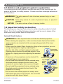
About this manual
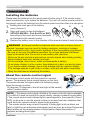
Various symbols are used in this manual. The meanings of these symbols are
described below.
WARNING This symbol indicates information that, if ignored, could possibly
result in personal injury or even death due to incorrect handling.
CAUTION This symbol indicates information that, if ignored, could possibly
result in personal injury or physical damage due to incorrect
handling.
NOTICE
This entry notices of fear of causing trouble.
Please refer to the pages written following this symbol.
NOTE • The information in this manual is subject to change without notice.
• The manufacturer assumes no responsibility for any errors that may appear in
this manual.
• The reproduction, transfer or copy of all or any part of this document is not
permitted without express written consent.
Trademark acknowledgment
• Mac® is a registered trademark of Apple Inc.
• Windows®, DirectDraw® and Direct3D® are registered trademarks of Microsoft Corporation
in the U.S. and/or other countries.
• VESA and DDC are trademarks of the Video Electronics Standard Association.
• HDMI, the HDMI logo, and High-Definition Multimedia Interface are trademarks or registered
trademarks of HDMI Licensing LLC in the United States and other countries.
• Trademark PJLink is a trademark applied for trademark rights
in Japan, the United States of America and other countries and
areas.
• Blu-ray Disc is a trademark.
All other trademarks are the properties of their respective owners.
ViewSonic
1
Pro9500
Contents
Introduction...................................................................................... 6
Features............................................................................................................... 6
Checking the contents of package........................................................................ 6
Part names........................................................................................................... 7
Setting up.......................................................................................... 8
Arrangement........................................................................................................ 8
Connecting with your devices.............................................................................. 9
Connecting to a power supply........................................................................... 18
Using the security bar and slot........................................................................... 18
Remote control............................................................................... 19
Installing the batteries........................................................................................ 19
About the remote control signal......................................................................... 19
Changing the frequency of remote control signal...................................................................... 20
Using as a simple PC mouse & keyboard....................................................................... 20
Power on/off.................................................................................... 21
Turning on the power......................................................................................... 21
Turning off the power......................................................................................... 21
Operating........................................................................................ 22
Adjusting the volume.......................................................................................... 22
Temporarily muting the sound............................................................................ 22
Selecting an input signal.................................................................................... 22
Searching an input signal................................................................................... 24
Selecting an aspect ratio.................................................................................... 24
Adjusting the projector's elevator....................................................................... 25
Adjusting the lens............................................................................................... 26
Using the automatic adjustment feature........................................................................ 27
Adjusting the position......................................................................................... 27
Correcting the distortion...................................................................................... 28
Using the magnify feature.................................................................................. 29
Temporarily freezing the screen......................................................................... 31
Temporarily blanking the screen ....................................................................... 31
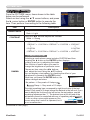
Using the menu function ................................................................................... 32
EASY MENU.................................................................................... 34
Aspect, Auto keystone,
Keystone,
Keystone, Perfect fit, Picture mode, Eco mode,
Mirror, Reset, Filter time, Language, Advanced menu, Exit
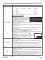
PICTURE menu................................................................................ 36
Brightness, Contrast, Gamma, Color temp, Color, Tint, Sharpness, Active iris, My memory
IMAGE menu.................................................................................... 39
Aspect, Over scan, V position, H position, H phase, H size, Auto adjust execute
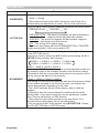
INPUT menu.................................................................................... 42
Progressive, Video nr, Color space, Component, Video format, Hdmi format, Hdmi range,
Computer in, Frame lock, Resolution
SETUP menu................................................................................... 46
Auto keystone,
Keystone,
Keystone, Perfect fit, Auto eco mode, Eco mode, Mirror,
Standby mode, Monitor out
ViewSonic
2
Pro9500
Contents
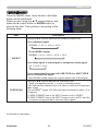
AUDIO menu.................................................................................... 49
Volume, Speaker, Audio source, Hdmi audio, Mic level, Mic volume
SCREEN menu................................................................................. 51
Language, Menu position, Blank, Start up, MyScreen, MyScreen Lock, Message,
Source name, Template, C.c.
OPTION menu................................................................................. 57
Auto search, Auto keystone, Direct power on, Auto power off, Usb type b, Lamp time,
Filter time, My button, My source, Service
NETWORK menu............................................................................. 67
Setup, Projector name, My image, Amx d.d., Presentation, Information, Service
SECURITY menu............................................................................. 74
Security password change, Myscreen password, Pin lock, Transition detector,
My text password, My text display, My text writing, Security indicator, Stack lock
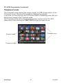
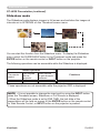
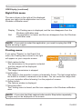
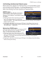
Presentation tools.......................................................................... 80
PC-LESS Presentation.................................................................................... 80
Thumbnail Mode, Full Screen Mode, Slideshow mode, Playlist
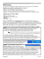
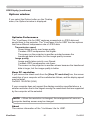
USB Display........................................................................................................ 89
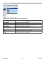
Right-Click menu, Floating menu, Options window
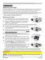
Maintenance................................................................................... 92
Replacing the lamp............................................................................................ 92
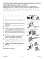
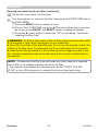
Cleaning and replacing the air filter.......................................................................... 94
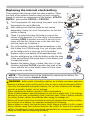
Replacing the internal clock battery. ........................................................................ 96
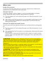
Other care.......................................................................................................... 97
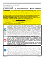
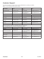
Troubleshooting.............................................................................. 98
Related messages............................................................................................. 98
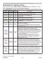
Regarding the indicator lamps........................................................................... 99
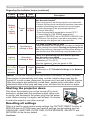
Shutting the projector down............................................................................. 101
Resetting all settings........................................................................................ 101
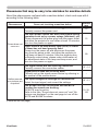
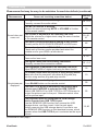
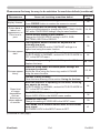
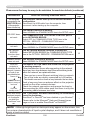
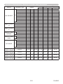
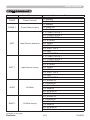
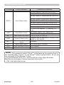
Phenomena that may be easy to be mistaken for machine defects........................... 102
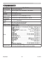
Specifications............................................................................... 106
ViewSonic
3
Pro9500
Contents
Network Guide
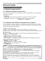
1. Connection to the Network . ................................................. 108
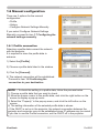
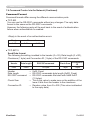
1.1 System requirements .............................................................................. 108
1.1.1 Required equipment preparation ...................................................................................108
1.1.2 Hardware and software requirement for computer ....................................................... 108
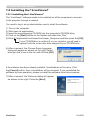
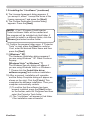
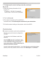
1.2 Installing the “LiveViewer” ....................................................................... 110
1.2.1 Installing the “LiveViewer” ..............................................................................................110
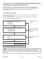
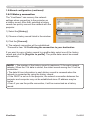
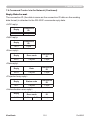
1.3 Process to connect the network .............................................................. 112
1.3.1 Process overview . ........................................................................................................ 112
1.3.2 Starting the “LiveViewer” . ..............................................................................................113
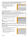
1.4 Selecting the network connection mode . ................................................ 114
1.4.1 Selecting either the wireless LAN or wired LAN ........................................................... 114
1.4.2 Selecting My Connection .............................................................................................. 116
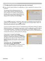
1.5 Selecting the network connection method .............................................. 116
1.5.1 Passcode connection . .................................................................................................. 117
1.6 Manual Configuration .............................................................................. 127
1.6.1 Profile connection ......................................................................................................... 127
1.6.2 History connection ........................................................................................................ 128
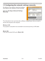
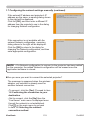
1.7 Configuring the network settings manually . ............................................ 129
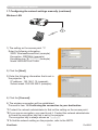
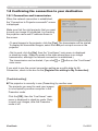
1.8 Confirming the connection to your destination ........................................ 134
1.8.1 Connection and transmission ....................................................................................... 134
1.8.2 Connection error ........................................................................................................... 136
1.9 Profile data .............................................................................................. 137
1.9.1 Outline of Profile data ................................................................................................... 137
1.9.2 Making Profile data ....................................................................................................... 137
1.9.3 Editing Profile data . ...................................................................................................... 138
1.9.4 Registering My Connection . ......................................................................................... 139
2. Network Presentation ........................................................... 141
2.1 Using the “LiveViewer” ............................................................................ 141
2.1.1 Main menu and Operating buttons ............................................................................... 141
2.1.2 Displaying the status . ................................................................................................... 143
2.1.3 Switching the display mode .......................................................................................... 144
2.1.4 Option menu ................................................................................................................. 145
2.2 Starting the Network Presentation . ......................................................... 147
2.2.1 Display mode ................................................................................................................ 147
2.2.2 Presenter mode ............................................................................................................ 148
2.2.3 Display User Name ....................................................................................................... 148
ViewSonic
4
Pro9500
Contents
3. Web Control ........................................................................... 149
3.1 Logon ......................................................................................................
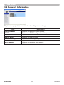
3.2 Network Information ................................................................................
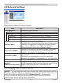
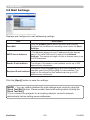
3.3 Network Settings .....................................................................................
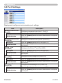
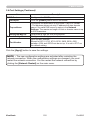
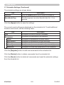
3.4 Port Settings . ..........................................................................................
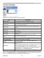
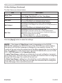
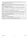
3.5 Mail Settings . ..........................................................................................
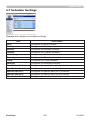
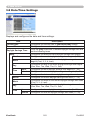
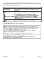
3.6 Alert Settings ...........................................................................................
3.7 Schedule Settings ...................................................................................
3.8 Date/Time Settings ..................................................................................
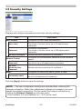
3.9 Security Settings .....................................................................................
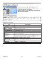
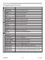
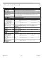
3.10 Projector Control ...................................................................................
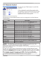
3.11 Remote Control .....................................................................................
3.12 Projector Status . ...................................................................................
3.13 Network Restart . ...................................................................................
150
152
153
154
156
157
158
162
164
165
171
172
173
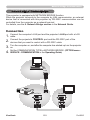
6.1 Connecting devices .................................................................................
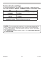
6.2 Communication setup . ............................................................................
6.3 Communication port ................................................................................
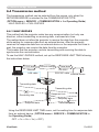
6.4 Transmission method ..............................................................................
178
179
179
180
4. My Image Function ................................................................ 174
5. Messeger Function . .............................................................. 176
6. Network Bridge Function . .................................................... 178
6.4.1 HALF-DUPLEX ............................................................................................................. 180
6.4.2 FULL-DUPLEX . ............................................................................................................ 181
7. Other Functions . ................................................................... 182
7.1 E-mail Alerts ............................................................................................
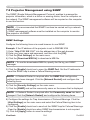
7.2 Projector Management using SNMP .......................................................
7.3 Event Scheduling ....................................................................................
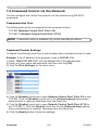
7.4 Command Control via the Network .........................................................
182
184
184
188
8. Troubleshooting .................................................................... 193
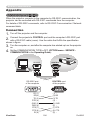
Appendix .................................................................................... 196
RS232............................................................................................................. 196
PJLink.............................................................................................................. 219
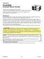
Instant Stack Guide......................................................................................... 221
End User License Agreement for the projector software................................. 258
ViewSonic
5
Pro9500
Introduction
Introduction
Features
The projector provides you with the broad use by the following features.
ü T
his projector has a variety of I/O ports that supposedly cover for any
business scene. The HDMI port can support various image equipment which
have digital interface to get clearer pictures on a screen.
ü This projector has a 1.7 times optical zoom, horizontal and vertical manual
lens shift, allowing flexible installation.
ü If you insert a USB storage device, such as a USB memory, into the USB
TYPE A port and select the port as the input source, you can view images
stored in the device.
ü This projector can be controlled and monitored via LAN connection.
ü The built-in 16W speaker can deliver sufficient sound volume in a large space
like a classroom without external speakers.
Contents of package
Your projector should come with the items shown below. Check that all the items
are included. Require of your dealer immediately if any items are missing.
(1)
(1) Remote control with two AA batteries
VIDEO
ASPECT
MAGNIFY
ON
(2) Power cord
AUTO
FREEZE
SEARCH
BLANK
PAGE
UP
VOLUME
MY BUTTON
1
2
MUTE
MENU
POSITION
(3) Computer cable
㧗
DOWN
KEYSTONE
(4)
MY SOURCE/
COMPUTER DOC.CAMERA
OFF
ENTER
ESC
(4) Lens cover
RESET
(5)
(2)
(5) User’s manuals (Book x1, CD x1)
(3)
NOTE • Keep the original packing materials for future reshipment. Be sure
to use the original packing materials when moving the projector. Use special
caution for the lens.
• The projector may make a rattling sound when tilted, moved or shaken, since
a flap to control the air flow inside of the projector has moved. Be aware that
this is not a failure or malfunction.
ViewSonic
6
Pro9500
Introduction
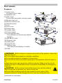
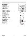
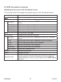
Part names
Projector
(1) Lamp cover
The lamp unit is inside.
(2) Speakers (x2)
(3) Filter cover
The air filter and intake vent are inside.
(4) Elevator feet (x2)
(5) Elevator buttons (x2)
(6) Remote sensor
(7) Lens
(8) Lens cover
(9) Pocket caps
(10) Intake vents
(11) Control panel
(12) Lens adjuster door
The adjusters for the lens are behind
the door.
(13) AC IN (AC inlet)
(14) Exhaust vent
(15) Rear panel
(16) Security bar
(17) Battery cover
The internal clock battery is inside.
(18) Heel
WARNING ►Do not open or remove any portion of the product, unless the
manuals direct it.
►Do not subject the projector to unstable conditions.
►Do not apply a shock or pressure to this product.
►Do not look into the lens and the openings on the projector while the lamp is
on.
►Keep the pocket caps away from children and pets. Make sure they do not
swallow the caps. If swallowed consult a physician immediately for emergency
treatment.
CAUTION ►Do not touch around the lamp cover and the exhaust
vents during use or just after use, since it is too hot.
►Do not attach anything onto the lens except the lens cover of this
projector because it could damage the lens, such as melting the lens.
(continued on next page)
ViewSonic
7
Pro9500
Introduction
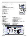
Part names (continued)
Control panel and Lens adjusters
(1) Lens adjuster door
(2) FOCUS ring
(3) ZOOM ring
(4) HORIZONTAL (horizontal) adjuster
(5) VERTICAL (vertical) adjuster
(6) LOCK (horizontal lens position lock)
(7) STANDBY/ON button
(8) INPUT button
(9) MENU button
(10) SECURITY indicator
(11) LAMP indicator
(12) TEMP indicator
(13) POWER indicator
(14) Cap storage pockets
LOCK
Rear panel
(1) LAN port
(2) USB TYPE A port
(3) HDMI port
(4) USB TYPE B port
(5) MIC port
(6) AUDIO IN1 port
(7) AUDIO IN2 port
(8) AUDIO IN3 (R,L) ports
(9) AUDIO OUT (R,L) ports
(10) COMPUTER IN1 port
(continued on next page)
ViewSonic
(11) COMPUTER IN2 ports
(G/Y, B/Cb/Pb, R/Cr/Pr, H, V)
(12) REMOTE CONTROL port
(13) MONITOR OUT port
(14) CONTROL port
(15) COMPONENT ports (Y,Cb/Pb, Cr/Pr)
(16) VIDEO port
(17) S-VIDEO ports
(18) Shutdown switch
(19) Security slot
8
Pro9500
Introduction
Part names (continued)
Remote control
(1) VIDEO button
(2) COMPUTER button
(3) SEARCH button
(4) STANDBY/ON button
(5) ASPECT button
(6) AUTO button
(7) BLANK button
(8) MAGNIFY - ON button
(9) MAGNIFY - OFF button
(10) MY SOURCE/DOC.CAMERA button
(11) VOLUME - button
(12) PAGE UP button
(13) PAGE DOWN button
(14) VOLUME + button
(15) MUTE button
(16) FREEZE button
(17) MY BUTTON - 1 button
(18) MY BUTTON - 2 button
(19) KEYSTONE button
(20) POSITION button
(21) MENU button
(22) ▲/▼/◄/► cursor buttons
(23) ENTER button
(24) ESC button
(25) RESET button
(26) Battery cover
ViewSonic
9
(2)
(1)
(6)
(5)
(16)
(8)
(9)
(19)
(17)
(20)
(22)
VIDEO
ASPECT
MAGNIFY
ON
MY SOURCE/
COMPUTER DOC.CAMERA
AUTO
FREEZE
SEARCH
BLANK
PAGE
UP
VOLUME
㧗
DOWN
OFF
KEYSTONE
(10)
(4)
(3)
(7)
(12)
(14)
(11)
(13)
(15)
(18)
(21)
(23)
(25)
MY BUTTON
1
2
MUTE
MENU
POSITION
ENTER
ESC
RESET
(24)
(26)
Back of
the remote control
Pro9500
Setting up
Setting up
Install the projector according to the environment
and manner the projector will be used in.
For the case of installation in a special state
such as ceiling mount, the specified mounting
accessories and service may be required.
Before installing the projector, consult your
dealer about your installation.
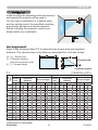
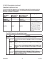
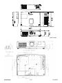
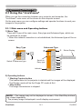
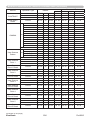
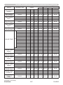
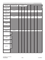
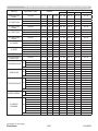
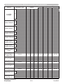
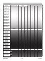
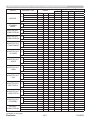
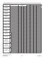
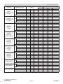
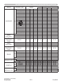
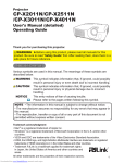
Arrangement
Refer to the following tables T-1 to determine the screen size and projection
distance. The values shown in the table are calculated for a full size screen.
Ⓗ × Ⓥ : Screen size
ⓐ : Projection distance
(from the projector's end)
ⓑ , ⓒ : Screen height
Projector top
Projector bottom
T-1
(1024X768) (±10%)
Screen
type
4:3
Screen
size
Ⓗ
Ⓥ ⓐ min.
ⓐ max.
(inch)
30
40
50
60
70
80
90
100
120
150
200
250
300
m
0.6
0.8
1.0
1.2
1.4
1.6
1.8
2.0
2.4
3.0
4.1
5.1
6.1
m
0.5
0.6
0.8
0.9
1.1
1.2
1.4
1.5
1.8
2.3
3.0
3.8
4.6
m inch
1.5 57
2.0 77
2.5 97
3.0 117
3.5 137
4.0 157
4.5 177
5.0 197
6.0 237
7.5 297
10.1 396
12.6 496
15.1 596
Projection
distance
m inch
0.9 34
1.2 46
1.5 58
1.8 70
2.1 82
2.4 94
2.7 106
3.0 118
3.6 142
4.5 179
6.1 239
7.6 300
9.1 360
(continued on next page)
ViewSonic
16:9
Screen height
ⓑ
ⓒ
cm inch cm inch
46 18 0 0
61 24 0 0
76 30 0 0
91 36 0 0
107 42 0 0
122 48 0 0
137 54 0 0
152 60 0 0
183 72 0 0
229 90 0 0
305 120 0 0
381 150 0 0
457 180 0 0
10
Screen
size
Projection
distance
Ⓗ
Ⓥ
ⓐ min.
ⓐ max.
m
0.7
0.9
1.1
1.3
1.5
1.8
2.0
2.2
2.7
3.3
4.4
5.5
6.6
m
0.4
0.5
0.6
0.7
0.9
1.0
1.1
1.2
1.5
1.9
2.5
3.1
3.7
m inch
0.9 37
1.3 50
1.6 63
1.9 76
2.3 90
2.6 103
2.9 116
3.3 129
3.9 155
5.0 195
6.6 261
8.3 327
10.0 393
m inch
1.6 63
2.1 84
2.7 106
3.2 128
3.8 150
4.3 171
4.9 193
5.5 215
6.6 258
8.2 323
11.0 432
13.7 541
16.5 650
Screen height
ⓑ
ⓒ
cm inch cm inch
44 17 -6 -2
58 23 -8 -3
73 29 -10 -4
87 34 -12 -5
102 40 -15 -6
116 46 -17 -7
131 51 -19 -7
145 57 -21 -8
174 69 -25 -10
218 86 -31 -12
291 114 -42 -16
363 143 -52 -20
436 172 -62 -25
Pro9500
Setting up
Arrangement (continued)
WARNING ►Install the projector where you can access the power
outlet easily. If an abnormality should occur, unplug the projector urgently.
Otherwise it could cause a fire or electric shock.
►Do not subject the projector to unstable conditions. If the projector falls
or topples over, it could result in injury or damage to the projector and the
surrounding things. Using a damaged projector could result in a fire and an
electric shock.
• Do not place the projector in unstable places, such as an inclined surface,
places subject to vibration, on top of a wobbly table or cart, or a surface that is
smaller than the projector.
• Do not put the projector on its side, front or rear position.
• Do not attach nor place anything on the projector unless otherwise specified in
the manual.
• Do not use any mounting accessories except the accessories specified by the
manufacturer. Read and keep the manuals of the accessories used.
• For special installation such as ceiling mounting, be sure to consult your dealer
beforehand.
►Do not install the projector near thermally conductive or flammable
things. Such things when heated by the projector could result in a fire and burns.
• Do not place the projector on a metal stand.
►Do not place the projector where any oils, such as cooking or machine
oil, are used. Oil may harm the product, resulting in malfunction, or falling from
the mounted position.
►Do not place the projector in a place where it may get wet. Getting the
projector wet or inserting liquid into the projector could cause a fire and an
electric shock, and damage the projector.
• Do not place the projector near water, such as in a bathroom, kitchen, or
poolside.
• Do not place the projector outdoors or by the window.
• Do not place anything containing liquid near the projector.
(continued on next page)
ViewSonic
11
Pro9500
Setting up
Arrangement (continued)
CAUTION ►Place the projector in a cool place with sufficient
ventilation. The projector may shutdown automatically or may malfunction if its
internal temperature is too high.
Using a damaged projector could result in a fire and an electric shock.
• Do not place the projector in direct sunlight or near hot objects such as heaters.
• Keep a space of 30 cm or more between a side of the projector and other
objects such as walls.
• Do not place the projector on carpet, cushions or bedding.
• Do not stop up, block nor cover the projector's vent holes. Do not place
anything around the projector that could be sucked in or stuck to the projector's
intake vents.
• Do not place the projector at places that are exposed to magnetic fields, doing
so can cause the cooling fans inside the projector to malfunction.
►Avoid placing the projector in smoky, humid or dusty place. Placing the
projector in such places could cause a fire, an electric shock and malfunction of
the projector.
• Do not place the projector near humidifiers. Especially for an ultrasonic
humidifier, chlorine and minerals contained in tap water are atomized and could
be deposited in the projector causing image degradation or other problems.
• Do not place the projector in a smoking area, kitchen, passageway or by the
window.
NOTICE • Position the projector to prevent light from directly hitting the
projector's remote sensor.
• Do not place the product in a place where radio interference may be caused.
• Check and correct the setting for FAN SPEED of SERVICE in the OPTION
menu according to the usage environment. If the projector is used with a wrong
setting, it may cause damage to the projector itself or the parts inside.
• Keep heat-sensitive things away from the projector. Otherwise, they may be
damaged by the heat from the projector.
ViewSonic
12
Pro9500
Setting up
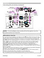
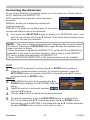
Connecting with your devices
Before connecting the projector to a device, consult the manual of the device to
confirm that the device is suitable for connecting with this projector and prepare
the required accessories, such as a cable in accord with the signal of the device.
Consult your dealer when the required accessory did not come with the product or
the accessory is damaged.
After making sure that the projector and the devices are turned off, perform
the connection, according to the following instructions. Refer to the figures in
subsequent pages.
Before connecting the projector to a network system, be sure to read Network
Guide too.
WARNING ►Use only the appropriate accessories. Otherwise it could
cause a fire or damage the projector and devices.
• Use only the accessories specified or recommended by the projector’s
manufacturer. It may be regulated under some standard.
• Neither disassemble nor modify the projector and the accessories.
• Do not use the damaged accessory. Be careful not to damage the accessories.
Route a cable so that it is neither stepped on nor pinched out.
CAUTION ►For a cable with a core at only one end, connect the end
with the core to the projector. That may be required by EMI regulations.
NOTE • Do not turn on or off the projector while connected to a device in
operation, unless that is directed in the manual of the device. Otherwise it may
cause malfunction in the device or projector.
• The function of some input ports can be selected according to your usage
requirements. Check the reference page indicated beside each port in the
following illustration.
• Be careful not to mistakenly connect a connector to a wrong port. Otherwise it
may cause malfunction in the device or projector.
- When connecting a connector to a port, make sure that the shape of the
connector fits the port.
- Tighten the screws to connect a connector equipped with screws to a port.
- Use the cables with straight plugs, not L-shaped ones, as the input ports of
the projector are recessed.
About Plug-and-Play capability
• Plug-and-Play is a system composed of a computer, its operating system
and peripheral equipment (i.e. display devices). This projector is VESA DDC
2B compatible. Plug-and-Play can be used by connecting this projector to a
computer that is VESA DDC (display data channel) compatible.
- Take advantage of this feature by connecting a computer cable to the
COMPUTER IN1 port (DDC 2B compatible). Plug-and-Play may not work
properly if any other type of connection is attempted.
- Please use the standard drivers in your computer as this projector is a Plugand-Play monitor.
(continued on next page)
ViewSonic
13
Pro9500
Setting up
Connecting with your devices (continued)
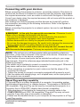
Computer
NOTE • Before connecting the projector to a computer, consult the computer’s
manual and check the compatibility of the signal level, the synchronization
methods and the display resolution output to the projector.
- Some signal may need an adapter to input this projector.
- Some computers have multiple screen display modes that may include some
signals which are not supported by this projector.
- Although the projector can display signals with resolution up to UXGA
(1600X1200), the signal will be converted to the projector’s panel resolution
before being displayed. The best display performance will be achieved if the
resolutions of the input signal and the projector panel are identical.
• If you connect this projector and a notebook computer, you need output the
display to an external monitor, or output simultaneously to the internal display
and an external monitor. Consult the computer's manual for the setting.
• Depending on the input signal, the automatic adjustment function of this
projector may take some time and not function correctly.
- Note that a composite sync signal or sync-on-green signal may confuse the
automatic adjustment function of this projector.
- If the automatic adjustment function does not work correctly, you may not see
the dialog to set the display resolution. In such a case, use an external display
device. You may be able to see the dialog and set an appropriate display
resolution.
(continued on next page)
ViewSonic
14
Pro9500
Setting up
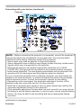
Connecting with your devices (continued)
Computer
Access
point
USB
storage
device
CAUTION ► Before connecting the projector to a network system be sure
to obtain the consent of the administrator of the network.
►Do not connect the LAN port to any network that might have the excessive
voltage.
►Before removing the USB storage device from the port of the projector, be
sure to use the REMOVE USB function on the thumbnail screen to secure your
data.
NOTE • If an oversized USB storage device blocks the LAN port, use a USB
extension cable to connect the USB storage device.
(continued on next page)
ViewSonic
15
Pro9500
Setting up
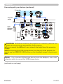
Connecting with your devices (continued)
Digital
video
device
VCR/DVD/Blu-ray Disc player
NOTE • The HDMI port of this model is compatible with HDCP (High-bandwidth Digital Content Protection) and therefore capable of displaying a video
signal from HDCP compatible DVD players or the like.
- The HDMI supports the following video signals:
480i@60,480p@60,576i@50,576p@50,720p@50/60,1080i@50/60,1080p@50/60
- This projector can be connected with another equipment that has HDMITM
connector, but with some equipment the projector may not work properly,
something like no video.
- Be sure to use an HDMITM cable that has the HDMITM logo.
- When the projector is connected with a device having DVI connector, use a
DVI to HDMITM cable to connect with the HDMI input.
(continued on next page)
ViewSonic
16
Pro9500
Setting up
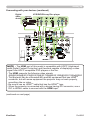
Connecting with your devices (continued)
Monitor
Speakers
(with an amplifier)
Microphone
system
Wired
remote
control
(optional)
NOTE • If a loud feedback noise is produced from the speaker, move the
microphone away from the speaker.
Microphone function
• You can connect a dynamic microphone to the MIC port with a 3.5 mm mini-plug.
In that case, the built-in speaker outputs the sound from the microphone, even
while the sound from the projector is output. You can input line level signal to
the MIC port from equipment such as wireless microphone. Select HIGH in the
MIC LEVEL item of the AUDIO menu when you input line level audio signal
to the MIC port. In the normal mode, the volume of the microphone can be
adjusted separately from the volume of the projector using the menu.
In the standby mode, the volume of the microphone is adjustable with the
VOLUME +/- buttons on the remote control, in synchronization with the volume
of the projector.
Even when the sound of projector is set to mute mode by the AUDIO SOURCE
function, the volume of the microphone is adjustable.
In both modes (standby or normal), the MUTE button on the remote control
works on the sounds of the microphone and the projector.
• This projector doesn't support plug-in power for the microphone.
ViewSonic
17
Pro9500
Setting up
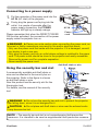
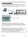
Connecting to a power supply
the connector of the power cord into the
1. Put
AC IN (AC inlet) of the projector.
plug the power cord’s plug into the
2. Firmly
outlet. In a couple of seconds after the
AC IN
power supply connection, the POWER
indicator will light up in steady orange.
Please remember that when the DIRECT POWER
ON function activated, the connection of the power
supply make the projector turn on.
Power
cord
WARNING ►Please use extra caution when connecting the power cord, as
incorrect or faulty connections may result in fire and/or electrical shock.
• Only use the power cord that came with the projector. If it is damaged, consult
your dealer to get a new one.
• Only plug the power cord into an outlet whose voltage is matched to the power
cord. The power outlet should be close to the projector and easily accessible.
Remove the power cord for complete separation.
• Never modify the power cord.
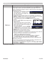
Using the security bar and slot
A commercially available anti-theft chain or
wire can be attached to the security bar on
the projector. Refer to the figure to choose
an anti-theft chain or wire.
Also this product has the security slot for the
Kensington lock.
For details, see the manual of the security
tool.
Anti-theft chain or wire
security bar
Security slot
WARNING ►Do not use the security bar and slot to prevent the projector
from falling down, since it is not designed for it.
CAUTION ►Do not place anti-theft chain or wire near the exhaust vents.
It may become too hot.
NOTE • The security bar and slot is not comprehensive theft prevention
measures. It is intended to be used as supplemental theft prevention measure.
ViewSonic
18
Pro9500
Remote control
Remote control
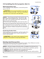
Installing the batteries
Please insert the batteries into the remote control before using it. If the remote control
starts to malfunction, try to replace the batteries. If you will not use the remote control for
long period, remove the batteries from the remote control and store them in a safe place.
Holding the hook part of the battery
1
2
3
cover, remove it.
Align and insert the two AA batteries
(HITACHI MAXELL, Part No.LR6 or R6P)
according to their plus and minus terminals
as indicated in the remote control.
Replace the battery cover in the direction of the arrow and snap it back into place.
1.
2.
3.
WARNING ►Always handle the batteries with care and use them only as
directed. Improper use may result in battery explosion, cracking or leakage,
which could result in fire, injury and/or pollution of the surrounding environment.
• Be sure to use only the batteries specified. Do not use batteries of different
types at the same time. Do not mix a new battery with used one.
•M
ake sure the plus and minus terminals are correctly aligned when loading a battery.
• Keep a battery away from children and pets.
• Do not recharge, short circuit, solder or disassemble a battery.
•D
o not place a battery in a fire or water. Keep batteries in a dark, cool and dry place.
• If you observe battery leakage, wipe out the leakage and then replace a battery.
If the leakage adheres to your body or clothes, rinse well with water immediately.
• Obey the local laws on disposing the battery.
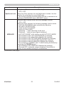
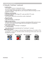
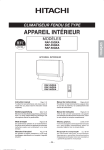
About the remote control signal
The remote control works with the projector’s remote
sensor. This projector has a remote sensor on the front.
The sensor senses the signal within the following range
when the sensor is active:
60 degrees (30 degrees to the left and right of the sensor)
within 3 meters about.
30° 30° 3m
(approx.)
NOTE • The remote control signal reflected in the screen or the like may be available.
If it is difficult to send the signal to the sensor directly, attempt to make the signal reflect.
• The remote control uses infrared light to send signals to the projector (Class 1
LED), so be sure to use the remote control in an area free from obstacles that
could block the remote control’s signal to the projector.
• The remote control may not work correctly if strong light (such as direct sun
light) or light from an extremely close range (such as from an inverter fluorescent
lamp) shines on the remote sensor of the projector. Adjust the position of
projector avoiding those lights.
ViewSonic
19
Pro9500
Remote control
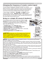
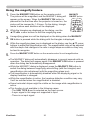
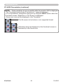
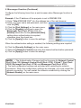
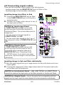
Changing the frequency of remote control signal
The accessory remote control has the two choices on signal
frequency Mode 1:NORMAL and Mode 2:HIGH. If the remote control
does not function properly, attempt to change the signal frequency.
In order to set the Mode, please keep pressing the combination of
two buttons listed below simultaneously for about 3 seconds.
(2)
(1) Set to Mode 1:NORMAL... VOLUME - and RESET buttons
(2) Set to Mode 2:HIGH... MAGNIFY OFF and ESC buttons
Please remember that the REMOTE FREQ. in the SERVICE item of
the OPTION menu of the projector to be controlled should be set to
the same mode as the remote control.
VIDEO
ASPECT
MAGNIFY
MY SOURCE/
COMPUTER DOC.CAMERA
AUTO
FREEZE
ON
SEARCH
BLANK
PAGE
UP
VOLUME
㧗
DOWN
OFF
KEYSTONE
MY BUTTON
1
2
(1)
MUTE
MENU
POSITION
ENTER
RESET
ESC
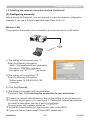
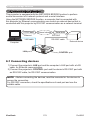
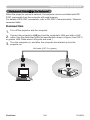
Using as a simple PC mouse & keyboard
The accessory remote control works as a simple mouse
and keyboard of the computer, when the projector’s USB
TYPE B port and the computer’s type A USB port are
connected and MOUSE is selected for the USB TYPE B
item in the OPTION menu.
USB TYPE B
port
(1) PAGE UP key: Press PAGE UP button.
(2) PAGE DOWN key: Press PAGE DOWN button.
(3) Mouse left button: Press ENTER button.
(4) Move pointer: Use the cursor buttons ▲, ▼, ◄ and ►.
(5) ESC key: Press ESC button.
(6) Mouse right button: Press RESET button.
VIDEO
ASPECT
MAGNIFY
ON
AUTO
FREEZE
(3)
(1)
SEARCH
BLANK
PAGE
UP
VOLUME
㧗
DOWN
OFF
KEYSTONE
NOTICE ►Improper use of the simple mouse & keyboard
function could damage your equipment. While using this
function, please connect this product only to a computer. Be
sure to check your computer’s manuals before connecting this
product to the computer.
MY SOURCE/
COMPUTER DOC.CAMERA
MY BUTTON
1
2
MENU
POSITION
(2)
MUTE
(4)
ENTER
ESC
RESET
(5)
NOTE When the simple mouse & keyboard function of this product does not work
(6)
correctly, please check the following.
• When a USB cable connects this projector with a computer having a built-in pointing
device (e.g. track ball) like a laptop PC, open BIOS setup menu, then select the external
mouse and disable the built-in pointing device, because the built-in pointing device may
have priority to this function.
• Windows 95 OSR 2.1 or higher is required for this function. And also this function may not work
depending on the computer’s configurations and mouse drivers. This function can work with the
computer which can operate general USB mouse or keyboard.
• You cannot do things like press two buttons at once (for instance, pressing two buttons
at the same time to move the mouse pointer diagonally).
• This function is activated only when the projector is working properly. This function is not
available in any of the following cases:
- While the lamp is warming up. (The POWER indicator blinks in green.)
- When either USB TYPE A or USB TYPE B port is selected.
- While displaying BLANK, TEMPLATE or MY IMAGE screen.
- When any menu is displayed on the screen.
-W
hile using the cursor buttons to operate the sound or screen functions such as adjusting the
sound volume, correcting the keystone, correcting the picture position and magnifying the screen.
ViewSonic
20
Pro9500
Power on/off
Power on/off
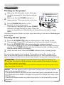
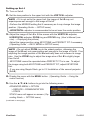
Turning on the power
sure that the power cord is firmly and
1. Make
correctly connected to the projector and the
2.
STANDBY/ON button
outlet.
Make sure that the POWER indicator is
steady orange. Then remove the lens cover.
3.
POWER indicator
Press STANDBY/ON button on the
projector or the remote control.
The projection lamp will light up and POWER
indicator will begin blinking in green. When the
power is completely on, the indicator will stop blinking and light in steady
green.
To display the picture, select an input signal according to the section Selecting an
input signal.
COMPUTER
VIDEO
MY SOURCE/A
DOC.CAMER
BLANK
AUTO
SEARCH
ASPECT
FREEZE
PAGE
UP
VOLUME
+
MAGNIFY
ON
ー
DOWN
MUTE
OFF
MY BUTTON
1
2
KEYSTONE
MENU
POSITION
ENTER
RESET
ESC
Turning off the power
the STANDBY/ON button on the projector or the remote control.
1. Press
The message “Power off?” will appear on the screen for about 5 seconds.
the STANDBY/ON button again while the message appears.
2. Press
The projector lamp will go off, and the POWER indicator will begin blinking in
3.
orange. Then POWER indicator will stop blinking and light in steady orange
when the lamp cooling is complete.
Attach the lens cover, after the POWER indicator turns in steady orange.
Do not turn the projector on for about 10 minutes or more after turning it off.
Also, do not turn the projector off shortly after turning it on. Such operations might
cause the lamp to malfunction or shorten the lifetime of some parts including the lamp.
WARNING ►A strong light is emitted when the projector’s power is on.
Do not look into the lens of the projector or look inside of the projector through
any of the projector’s openings.
►Do not touch around the lamp cover and the exhaust vents during use or just
after use, since it is too hot.
NOTE • Turn the power on/off in right order. Please power on the projector
prior to the connected devices.
• This projector has the function that can make the projector automatically turn on/
off. Please refer to the DIRECT POWER ON and AUTO POWER OFF items of the
OPTION menu.
• Use the shutdown switch only when the projector is not turned off by normal
procedure.
ViewSonic
21
Pro9500
Operating
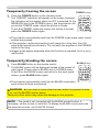
Operating
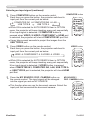
VOLUME +/- button
Adjusting the volume
VIDEO
1.
MY SOURCE/
COMPUTER DOC.CAMERA
Use the VOLUME +/VOLUME - buttons to adjust the volume.
A dialog will appear on the screen to aid you in adjusting the
volume. If you do not do anything, the dialog will automatically
disappear after a few seconds.
● When is selected for current picture input port, the volume adjustment is
disabled. Please see AUDIO SOURCE item of AUDIO menu.
● Even if the projector is in the standby mode, the volume is adjustable when
both of the following conditions are true:
- An option other than is selected for STANDBY in the AUDIO SOURCE
item of the AUDIO menu.
- NORMAL is selected in the STANDBY MODE item of the SETUP menu.
● In the standby mode, the volume of the microphone is adjustable with the
VOLUME +/- buttons on the remote control, in synchronization with the volume
of the projector.
ASPECT
MAGNIFY
AUTO
FREEZE
ON
SEARCH
BLANK
PAGE
UP
VOLUME
㧗
DOWN
OFF
KEYSTONE
MY BUTTON
1
2
MUTE
MENU
POSITION
ENTER
RESET
ESC
MUTE button
Temporarily muting the sound
MUTE button on the remote control.
1. Press
A dialog will appear on the screen indicating that you have muted
the sound.
To restore the sound, press the MUTE, VOLUME + or
VOLUME - button. Even if you do not do anything, the dialog
will automatically disappear after a few seconds.
VIDEO
ASPECT
MAGNIFY
ON
MY SOURCE/
COMPUTER DOC.CAMERA
AUTO
FREEZE
SEARCH
BLANK
PAGE
UP
VOLUME
㧗
DOWN
OFF
KEYSTONE
MY BUTTON
1
2
MUTE
● When is selected for current picture input port, the sound is always muted.
Please see AUDIO SOURCE item of AUDIO menu.
● C.C. (Closed Caption) is automatically activated when sound is muted and an
input signal containing C.C. is received. This function is available only when
the signal is NTSC for VIDEO or S-VIDEO, or 480i@60 for COMPONENT,
COMPUTER IN1 or COMPUTER IN2, and when AUTO is selected for
DISPLAY in the C.C. menu under the SCREEN menu.
MENU
POSITION
ENTER
ESC
RESET
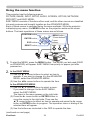
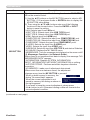
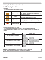
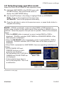
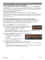
Selecting an input signal
INPUT button on the projector.
1. Press
Each time you press the button, the projector switches its
input port from the current port as below.
INPUT
button
COMPUTER IN1 COMPUTER IN2 LAN
VIDEO
USB TYPE A
S-VIDEO
USB TYPE B
COMPONENT (Y, Cb/Pb, Cr/Pr)
HDMI
●W
hile ON is selected for AUTO SEARCH item in OPTION menu, the projector will
keep checking the ports in above order repeatedly till an input signal is detected.
● It may take several seconds to project the images from the USB TYPE B port.
(continued on next page)
ViewSonic
22
Pro9500
Operating
Selecting an input signal (continued)
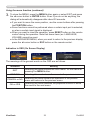
COMPUTER button on the remote control.
1. Press
Each time you press the button, the projector switches its
COMPUTER button
input port from the current port as below.
COMPUTER IN1 COMPUTER IN2 LAN
USB TYPE B
USB TYPE A
VIDEO
ASPECT
MAGNIFY
MY SOURCE/
COMPUTER DOC.CAMERA
AUTO
FREEZE
ON
● While ON is selected for AUTO SEARCH item in OPTION
menu, the projector will keep checking every port sequentially
till an input signal is detected. If COMPUTER button is
pressed when VIDEO, S-VIDEO, COMPONENT or HDMI port
is selected, the projector will check COMPUTER IN1 port first.
● It may take several seconds to project the images from the
USB TYPE B port.
VIDEO button on the remote control.
1. Press
Each time you press the button, the projector switches its
BLANK
PAGE
UP
VOLUME
KEYSTONE
MY BUTTON
1
MENU
RESET
ESC
VIDEO button
VIDEO
MAGNIFY
MY SOURCE/
COMPUTER DOC.CAMERA
AUTO
FREEZE
SEARCH
BLANK
PAGE
UP
VOLUME
㧗
DOWN
OFF
into the signal you set as MY SOURCE.
MUTE
ENTER
ON
the MY SOURCE / DOC. CAMERA button on
1. Press
the remote control. The input signal will be changed
2
POSITION
ASPECT
● While ON is selected for AUTO SEARCH item in OPTION
menu, the projector will keep checking every port sequentially
till an input signal is detected. If VIDEO button is pressed
when COMPUTER IN1, COMPUTER IN2, LAN, USB TYPE A
or USB TYPE B port is selected, the projector will check HDMI
port first.
㧗
DOWN
OFF
input port from the current port as below.
HDMI COMPONENT S-VIDEO VIDEO
SEARCH
KEYSTONE
MY BUTTON
1
2
MUTE
MENU
POSITION
ENTER
RESET
ESC
MY SOURCE /
DOC. CAMERA button
● This function also can use for document camera. Select the
input port that connected the document camera.
VIDEO
ASPECT
MAGNIFY
ON
MY SOURCE/
COMPUTER DOC.CAMERA
AUTO
FREEZE
SEARCH
BLANK
PAGE
UP
VOLUME
㧗
DOWN
OFF
KEYSTONE
MY BUTTON
1
2
MUTE
MENU
POSITION
ENTER
ESC
ViewSonic
23
RESET
Pro9500
Operating
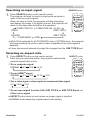
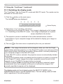
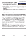
Searching an input signal
SEARCH button
SEARCH button on the remote control.
1. Press
The projector will start to check its input ports as below in
VIDEO
order to find any input signals.
When an input is found, the projector will stop searching
and display the image. If no signal is found, the projector will
return to the state selected before the operation.
COMPUTER IN1 COMPUTER IN2 LAN
VIDEO
USB TYPE A
S-VIDEO
COMPONENT
ASPECT
MAGNIFY
AUTO
FREEZE
ON
SEARCH
BLANK
PAGE
UP
VOLUME
㧗
DOWN
OFF
KEYSTONE
MY BUTTON
1
2
MUTE
MENU
POSITION
ENTER
RESET
ESC
USB TYPE B
HDMI
MY SOURCE/
COMPUTER DOC.CAMERA
● While ON is selected for AUTO SEARCH item in OPTION menu, the projector
will keep checking the ports in above order repeatedly till an input signal is
detected.
● It may take several seconds to project the images from the USB TYPE B port.
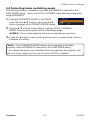
Selecting an aspect ratio
ASPECT button on the remote control.
1. Press
Each time you press the button, the projector switches the
ASPECT button
mode for aspect ratio in turn.
F
or a computer signal
4:3
16:9
NORMAL
VIDEO
ASPECT
MAGNIFY
16:10
ON
16:10
AUTO
FREEZE
SEARCH
BLANK
PAGE
UP
VOLUME
14:9
㧗
DOWN
OFF
KEYSTONE
F
or an HDMITM signal
4:3
16:9
NORMAL
MY SOURCE/
COMPUTER DOC.CAMERA
MY BUTTON
1
2
MUTE
MENU
POSITION
ENTER
ESC
RESET
For a video signal, s-video signal or component video signal
16:9
14:9
4:3
F
or an input signal from the LAN, USB TYPE A or USB TYPE B port, or
if there is no signal
● ASPECT button does not work when no proper signal is inputted.
● NORMAL mode keeps the original aspect ratio setting.
ViewSonic
24
Pro9500
Operating
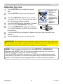
Adjusting the projector’s elevator
When the place to put the projector is slightly uneven
to the left or right, use the elevator feet to place the
projector horizontally.
Using the feet can also tilt the projector in order to
project at a suitable angle to the screen, elevating the
front side of the projector within 12 degrees.
This projector has 2 elevator feet and 2 elevator buttons.
An elevator foot is adjustable while pushing the elevator
button on the same side as it.
Holding the projector, push the elevator buttons to
loose the elevator feet.
Position the front side of the projector to the desired
height.
Release the elevator buttons in order to lock the
elevator feet.
After making sure that the elevator feet are locked,
put the projector down gently.
If necessary, the elevator feet can be manually
twisted to make more precise adjustments. Hold the
projector when twisting the feet.
1.
2.
3.
4.
5.
To loose an
elevator foot, push
the elevator button
on the same side
as it.
To finely
adjust, twist
the foot.
CAUTION ►Do not handle the elevator buttons without holding the
projector, since the projector may drop down.
►Do not tilt the projector other than elevating its front within 12 degrees using
the adjuster feet. A tilt of the projector exceeding the restriction could cause
malfunction or shortening the lifetime of consumables, or the projector itself.
ViewSonic
25
Pro9500
Operating
Adjusting the lens
1.
2.
Use the ZOOM ring to adjust the screen
size.
Use the FOCUS ring to focus the picture.
3.
Turn the VERTICAL adjuster fully counter
clockwise. Then turn it clockwise and adjust
the vertical lens position upward.
Turn the LOCK counter clockwise to loosen
the lock of the HORIZONTAL adjuster.
Turn the HORIZONTAL adjuster clockwise
or counter clockwise to adjust the horizontal
lens position.
4.
5.
6.
7.
FOCUS ring
ZOOM ring
LOCK
LOCK
(Horizontal
adjuster lock)
HORIZONTAL
adjuster
VERTICAL
adjuster
Turn the LOCK fully clockwise to tighten it and lock the horizontal lens
position.
Use the FOCUS ring to focus the picture.
CAUTION ►Operate the lens adjusters gently as the lens may malfunction
when subjected to shocks. It may need more strength to turn the adjusters near
the adjustment limits. Be careful not to apply too much strength.
NOTE • Use a hexagon wrench to turn the VERTICAL, HORIZONTAL
adjusters and LOCK. If you do not have a hexagon wrench, you can use a
flathead screwdriver with more careful handling.
• Use the LOCK so that the lens does not shift from the adjusted horizontal
lens position. Adjusting the vertical lens position may shift the horizontal lens
position. This projector is not equipped with a lock for vertical lens position.
ViewSonic
26
Pro9500
Operating
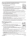
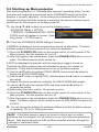
Using the automatic adjustment feature
AUTO button on the remote control.
1. Press
Pressing this button performs the following.
AUTO button
MY SOURCE/
COMPUTER DOC.CAMERA
F
or a computer signal
The vertical position, the horizontal position and the horizontal
phase will be automatically adjusted.
Make sure that the application window is set to its maximum size
prior to attempting to use this feature. A dark picture may still be
incorrectly adjusted. Use a bright picture when adjusting.
F
or a video signal and s-video signal
The video format best suited for the respective input signal will be selected
automatically. This function is available only when the AUTO is selected for the
VIDEO FORMAT item in the INPUT menu. The vertical position and horizontal
position will be automatically set to the default.
For a component video signal
The vertical position and horizontal position will be automatically set to the default.
The horizontal phase will be automatically adjusted.
● The automatic adjustment operation requires approx. 10 seconds. Also please
note that it may not function correctly with some input.
● When this function is performed for a video signal, a certain extra such as a line
may appear outside a picture.
● When this function is performed for a computer signal, a black frame may be
displayed on the edge of the screen, depending on the PC model.
●T
he items adjusted by this function may vary when the FINE or DISABLE is selected
for the AUTO ADJUST item of the SERVICE item in the OPTION menu.
VIDEO
ASPECT
AUTO
SEARCH
BLANK
PAGE
UP
VOLUME
FREEZE
MAGNIFY
ON
㧗
DOWN
OFF
KEYSTONE
MY BUTTON
1
2
MUTE
MENU
POSITION
ENTER
RESET
ESC
VIDEO
ASPECT
Adjusting the position
MAGNIFY
ON
MY SOURCE/
COMPUTER DOC.CAMERA
AUTO
FREEZE
SEARCH
BLANK
PAGE
UP
VOLUME
1.
㧗
DOWN
OFF
Press POSITION button on the remote control when no menu is
indicated.
The “POSITION” indication will appear on the screen.
Use the ▲/▼/◄/► cursor buttons to adjust the picture position.
When you want to reset the operation, press RESET button on
the remote control during the operation.
To complete this operation, press POSITION button again. Even if
you do not do anything, the dialog will automatically disappear
POSITION button
after a few seconds.
hen this function is performed on a video signal or an s-video signal, some image
●W
such as an extra-line may appear at outside of the picture.
● When this function is performed on a video signal or s-video signal, the range
of this adjustment depends on OVER SCAN in IMAGE menu setting. It is not
possible to adjust when OVER SCAN is set to 10.
● If POSITION button is pressed when a menu is indicated on screen, the displayed
picture does not move its position but the menu does.
● This function is unavailable for a signal from the LAN, USB TYPE A, USB TYPE B
or HDMI port.
KEYSTONE
MY BUTTON
1
ViewSonic
MUTE
MENU
POSITION
2.
2
ENTER
ESC
27
RESET
Pro9500
Operating
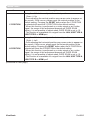
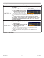
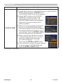
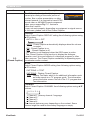
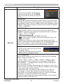
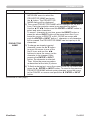
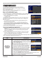
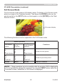
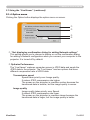
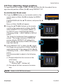
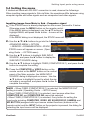
Correcting the distortion
To correct the distortion of projected screen, you can select one of three options,
AUTO, MANUAL and PERFECT FIT.
AUTO: performs the automatic vertical keystone
correction.
MANUAL: allows you to adjust the vertical and
horizontal keystone.
PERFECT FIT: allows you to adjust each of the screen
corners and sides to correct the distortion.
1.
First press the KEYSTONE button to display the KEYSTONE menu, and
point at one of items with the ▲/▼ buttons. Then follow the procedure shown
below for the item you selected.
NOTE • The menu or dialog will automatically disappear after several seconds
of inactivity. Pressing the KEYSTONE button again finishes the operation and
closes the menu or dialog.
• When the screen is adjusted by PERFECT FIT, neither AUTO nor MANUAL is
selectable. If you wish to use these functions, refer to step 3 in the PERFECT
FIT item to initialize the adjustment of PERFECT FIT.
• When TRANSITION DETECTOR is ON, these functions are not available.
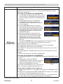
AUTO
When AUTO is pointed at, pressing the ► or ENTER button performs
automatic vertical keystone correction. To close the operation, press the
KEYSTONE button, or pointed at the EXIT in the dialog with ▲/▼ buttons
and press the ► or ENTER button.
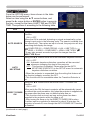
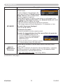
MANUAL
When MANUAL is pointed at, pressing the ► or
ENTER button displays the KEYSTONE_MANUAL
dialog.
Select the vertical or horizontal keystone ( / )
with the ▲/▼ buttons.
Use the ◄/► buttons to adjust the keystone distortion.
2.
2.
3.
4.
5.
To close the operation, press the KEYSTONE button, or pointed at the
EXIT in the dialog with ▲/▼ buttons and press the ► or ENTER button.
Alternatively, point at RETURN in the dialog with the ▲/▼ buttons and press
the ◄ or ENTER button to return to the menu in step 1.
ViewSonic
28
Pro9500
Operating
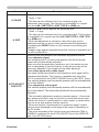
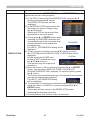
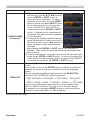
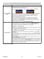
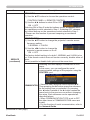
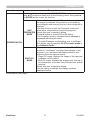
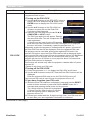
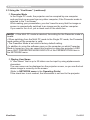
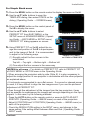
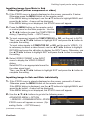
PERFECT FIT
When PERFECT FIT is pointed at,
pressing the ► or ENTER button
displays the KEYSTONE_PERFECT
FIT dialog.
If it is necessary to initialize the
current adjustment, point at RESET in
the dialog with the RESET button, and
press the ENTER or INPUT button.
Select one of the corners or sides
to be adjusted with the ▲/▼/◄/►
buttons and press the ENTER or
INPUT button.
Adjust the selected part as below.
2.
3.
4.
5.
● For adjusting a corner, use the ▲/▼/◄/► buttons to adjust the position of the
corner.
●F
or adjusting the upper or lower side, use the ◄/► buttons to select any one
point on the side, and use the ▲/▼ buttons to adjust the distortion of the side.
● For adjusting the left or right side, use the ▲/▼ buttons to select any one
point on the side, and use the ◄/► buttons to adjust the distortion of the
side.
● To adjust another corner or side press the ENTER or INPUT button and
follow the procedure from step 4.
NOTE • Each corner and side can be adjusted individually but in some cases
it may be adjusted in conjunction with another corner or side. This is due to
control restrictions and not a malfunction.
6.
To close the operation, press the KEYSTONE button, or point at EXIT in the
dialog with ▲/▼ buttons and press the ► or ENTER button. Alternatively,
point at RETURN in the dialog with the ▲/▼ buttons and press the ◄ or
ENTER button to return to the menu in step 1.
ViewSonic
29
Pro9500
Operating
Using the magnify feature
the MAGNIFY ON button on the remote control.
1. Press
The picture will be magnified, and the MAGNIFY dialog will
appear on the screen. When the MAGNIFY ON button is
pressed for the first time after the projector is turned on, the
picture will be zoomed by 1.5 times. On the dialog, triangle
marks to show each direction will be displayed.
MAGNIFY
ON/OFF button
VIDEO
ASPECT
MAGNIFY
ON
MY SOURCE/
COMPUTER DOC.CAMERA
AUTO
FREEZE
SEARCH
BLANK
PAGE
UP
VOLUME
the triangles are displayed on the dialog, use the
2. While
▲/▼/◄/► cursor buttons to shift the magnifying area.
㧗
DOWN
OFF
KEYSTONE
MY BUTTON
1
2
MUTE
MENU
POSITION
glass icon will be displayed on the dialog when the MAGNIFY
3. AONmagnifying
button is pressed while the dialog with the triangles is displayed.
ENTER
RESET
ESC
the magnifying glass icon is displayed on the dialog, use the ▲/▼ cursor
4. While
buttons to adjust the magnification ratio. The magnification ratio will be adjusted
with fine steps. And changes in the ratio in single steps are subtle so they may
be hard to recognize.
5. Press the MAGNIFY OFF button on the remote control to exit magnification.
● The MAGNIFY dialog will automatically disappear in several seconds with no
operation. The dialog will appear again if the MAGNIFY ON button is pressed
when the dialog has automatically disappeared.
● While the MAGNIFY dialog is displayed, press the MAGNIFY ON button to
switch the dialog between magnifying area shifting (with the triangles) and
magnification ratio adjustment (with the magnifying glass icon).
● The magnification is automatically disabled when the displaying signal or its
display condition is changed.
● While the magnification is active, the keystone distortion condition may vary.
It will be restored when the magnification is disabled.
● Some horizontal stripes might be visible on the image while magnification is
active.
● This function is not available in the following cases:
-The USB TYPE A port is selected as the input source.
-A sync signal in the range not supported is input.
-There is no input signal.
ViewSonic
30
Pro9500
Operating
Temporarily freezing the screen
1.
Press the FREEZE button on the remote control.
The “FREEZE” indication will appear on the screen (however,
the indication will not appear when the OFF is selected for the
MESSAGE item in the SCREEN menu), and the projector will
go into the FREEZE mode, which the picture is frozen.
To exit the FREEZE mode and restore the screen to normal,
press the FREEZE button again.
FREEZE button
VIDEO
MY SOURCE/
COMPUTER DOC.CAMERA
AUTO
ASPECT
MAGNIFY
FREEZE
ON
SEARCH
BLANK
PAGE
UP
VOLUME
㧗
DOWN
OFF
KEYSTONE
MY BUTTON
1
2
MUTE
MENU
POSITION
ENTER
● The projector automatically exits from the FREEZE mode when some control
buttons are pressed.
● If the projector continues projecting a still image for a long time, the LCD
panel might possibly be burned in. Do not leave the projector in the FREEZE
mode for too long.
● Images might appear degraded when this function is operated, but it is not a
malfunction.
RESET
ESC
Temporarily blanking the screen
BLANK button on the remote control.
1. Press
The BLANK screen will be displayed instead of the screen of
input signal. Please refer to BLANK item in SCREEN menu.
To exit from the BLANK screen and return to the input signal
screen, press BLANK button again.
BLANK button
VIDEO
ASPECT
MAGNIFY
ON
AUTO
FREEZE
SEARCH
BLANK
PAGE
UP
VOLUME
㧗
DOWN
OFF
KEYSTONE
● The projector automatically exits from the BLANK mode when
some control buttons are pressed.
MY SOURCE/
COMPUTER DOC.CAMERA
MY BUTTON
1
2
MUTE
MENU
POSITION
ENTER
ESC
RESET
CAUTION ►If you wish to have a blank screen while the projector's lamp
is on, use the BLANK function above.
Taking any other action may cause the damage on the projector.
NOTE • The sound is not connected with the BLANK screen function. If
necessary, set the volume or mute first. To display the BLANK screen and mute
the sound at one time, use AV MUTE function.
ViewSonic
31
Pro9500
Operating
Using the menu function
This projector has the following menus:
PICTURE, IMAGE, INPUT, SETUP, AUDIO, SCREEN, OPTION, NETWORK,
SECURITY and EASY MENU.
EASY MENU consists of functions often used, and the other menus are classified
into each purpose and brought together as the ADVANCED MENU.
Each of these menus is operated using the same methods. While the projector
is displaying any menu, the MENU button on the projector works as the cursor
buttons. The basic operations of these menus are as follows.
POSITION button
MENU
POSITION
ENTER button
ENTER
ESC button
RESET
ESC
MENU button
(Cursor buttons)
Cursor
buttons
RESET button
CE/
RA
SOUR
MY CAME
DOC.
O
UTER
COMP
NK
BLA
RCH
O
VIDE
SEA
AUT
ECT
ASP
VOLU
ME
+
E
PAG UP
ー
EZE
FRE
DOWN
IFY
MAGN
E
MUT
ON
ON
2
BUTT
MY 1
OFF
U
TONE
KEYS
MEN
N
ITIO
ER
ENT
POS
ET
RES
ESC
start the MENU, press the MENU button. The MENU you last used (EASY
1. To
or ADVANCED) will appear. EASY MENU has priority to appear just after
powered on.
EASY MENU
2. In(1)the
Use the ▲/▼ cursor buttons to select an item to
operate. If you want to change it to the ADVANCED
MENU, select the ADVANCED MENU.
(2) Use the ◄/► cursor buttons to operate the item.
In the ADVANCED MENU
(1) Use the ▲/▼ cursor buttons to select a menu.
If you want to change it to the EASY MENU,
select the EASY MENU.
The items in the menu appear on the right side.
(2) Press the ► cursor button or ENTER button to
move the cursor to the right side. Then use the
▲/▼ cursor buttons to select an item to operate and press the ► cursor
button or ENTER button to progress. The operation menu or dialog of the
selected item will appear.
(3) Use the buttons as instructed in the OSD to operate the item.
(continued on next page)
ViewSonic
32
Pro9500
Operating
Using the menu function (continued)
close the MENU, press the MENU button again or select EXIT and press
3. To
the ◄ cursor button or ENTER button. Even if you do not do anything, the
dialog will automatically disappear after about 30 seconds.
● If you want to move the menu position, use the cursor buttons after pressing
the POSITION button.
● Some functions cannot be performed when a certain input port is selected,
or when a certain input signal is displayed.
● When you want to reset the operation, press RESET button on the remote
control during the operation. Note that some items (ex. LANGUAGE,
VOLUME) cannot be reset.
● In the ADVANCED MENU, when you want to return to the previous display,
press the ◄ cursor button or ESC button on the remote control.
Indication in OSD (On Screen Display)
The meanings of the general words on the OSD are as follows.
Indication
Meaning
EXIT
Selecting this word finishes the OSD menu. It's the same as
pressing the MENU button.
RETURN
Selecting this word returns the menu to the previous menu.
CANCEL or NO
OK or YES
ViewSonic
Selecting this word cancels the operation in the present
menu and returns to the previous menu.
Selecting this word executes the prepared function or shifts
the menu to the next menu.
33
Pro9500
EASY MENU
EASY MENU
From the EASY MENU, items shown in the table
below can be performed.
Select an item using the ▲/▼ cursor buttons. Then
perform it according to the following table.
Item
ASPECT
AUTO KEYSTONE
Description
Using the ◄/► buttons switches the mode for aspect ratio.
See the ASPECT item in IMAGE menu.
Using the ► button executes the auto keystone function.
See the AUTO KEYSTONE item in SETUP menu.
KEYSTONE
Using the ◄/► buttons corrects the vertical keystone distortion.
KEYSTONE item in SETUP menu.
See the
KEYSTONE
Using the ◄/► buttons corrects the horizontal keystone distortion.
KEYSTONE in SETUP menu.
See the
PERFECT FIT
Pressing the ► button displays the KEYSTONE_PERFECT FIT
dialog. See the PERFECT FIT item in SETUP menu.
Using the ◄/► buttons switches the picture mode.
The picture modes are combinations of GAMMA and COLOR TEMP
settings. Choose a suitable mode according to the projected source.
NORMAL ó CINEMA ó DYNAMIC ó BOARD(BLACK)
DAYLIGHT ó WHITEBOARD ó BOARD(GREEN)
PICTURE MODE
NORMAL
CINEMA
DYNAMIC
BOARD(BLACK)
BOARD(GREEN)
WHITEBOARD
Daylight Mode
GAMMA
1 DEFAULT
2 DEFAULT
3 DEFAULT
4 DEFAULT
4 DEFAULT
5 DEFAULT
6 DEFAULT
COLOR TEMP
2 MID
3 LOW
1 HIGH
4 Hi-BRIGHT-1
5 Hi-BRIGHT-2
2 MID
6 Hi-BRIGHT-3
• When the combination of GAMMA and COLOR TEMP differs
from pre-assigned modes above, the display on the menu for the
PICTURE MODE is “CUSTOM”. Please refer to the GAMMA and
COLOR TEMP items in PICTURE menu.
• Lines or other noise might appear on the screen when this function
is operated, but it is not a malfunction.
(continued on next page)
ViewSonic
34
Pro9500
EASY MENU
Item
ECO MODE
MIRROR
Description
Using the ◄/► buttons turns off/on the Eco mode.
See the ECO MODE item in SETUP menu.
Using the ◄/► buttons switches the mode for mirror status.
See the MIRROR item in SETUP menu.
RESET
Performing this item resets all of the EASY MENU items except the
FILTER TIME and LANGUAGE.
A dialog is displayed for confirmation. Selecting the OK using the ►
button performs resetting.
FILTER TIME
The usage time of the air filter is shown in the menu.
Performing this item resets the filter time which counts usage time
of the air filter.
A dialog is displayed for confirmation. Selecting the OK using the ►
button performs resetting.
See the FILTER TIME item in OPTION menu.
LANGUAGE
Using the ◄/► buttons changes the display language.
See the LANGUAGE item in SCREEN menu.
Press the ► or ENTER button to use the menu of PICTURE,
ADVANCED MENU IMAGE, INPUT, SETUP, AUDIO, SCREEN, OPTION, NETWORK or
SECURITY.
EXIT
ViewSonic
Press the ◄ or ENTER button to finish the OSD menu.
35
Pro9500
PICTURE menu
PICTURE menu
From the PICTURE menu, items shown in the table
below can be performed.
Select an item using the ▲/▼ cursor buttons, and press
the ► cursor button or ENTER button to execute the
item. Then perform it according to the following table.
Item
BRIGHTNESS
CONTRAST
Description
Using the ◄/► buttons adjusts the brightness.
Dark ó Light
Using the ◄/► buttons adjusts the contrast.
Weak ó Strong
Using the ▲/▼ buttons switches the gamma mode.
1 DEFAULT 1 CUSTOM 2 DEFAULT 2 CUSTOM 3 DEFAULT
3 CUSTOM
6 CUSTOM
6 DEFAULT 5 CUSTOM 5 DEFAULT 4 CUSTOM 4 DEFAULT
To adjust CUSTOM
GAMMA
Selecting a mode whose name includes CUSTOM and then
pressing the ► button or the ENTER button displays
a dialog to aid you in adjusting the mode.
This function is useful when you want to
change the brightness of particular tones.
Choose an item using the ◄/► buttons,
and adjust the level using the ▲/▼ buttons.
You can display a test pattern for checking the effect of your
adjustment by pressing the ENTER button.
Each time you press the ENTER button, the
pattern changes as below.
No pattern ð Gray scale of 9 steps
Ramp Gray scale of 15 steps
The eight equalizing bars correspond to eight tone levels of the test
pattern (Gray scale of 9 steps) except the darkest in the left end. If you
want to adjust the 2nd tone from left end on the test pattern, use the
equalizing adjustment bar “1”. The darkest tone at the left end of the
test pattern cannot be controlled with any of equalizing adjustment bar.
• Lines or other noise might appear on the
screen when this function is operated, but it
is not a malfunction.
(continued on next page)
ViewSonic
36
Pro9500
PICTURE menu
Item
Description
Using the ▲/▼ buttons switches the color temperature mode.
2 MID
2 CUSTOM
1 HIGH 1 CUSTOM
3 LOW
6 Hi-BRIGHT-3
3 CUSTOM
6 CUSTOM
5 CUSTOM 5 Hi-BRIGHT-2 4 CUSTOM 4 Hi-BRIGHT-1
To adjust CUSTOM
COLOR TEMP
Selecting a mode whose name includes
CUSTOM and then pressing the ► button
or the ENTER button displays a dialog
to aid you in adjusting the OFFSET and
GAIN of the selected mode.
OFFSET adjustments change the color intensity on the whole tones
of the test pattern.
GAIN adjustments mainly affect color intensity on the brighter tones
of the test pattern.
Choose an item using the ◄/► buttons, and adjust the level using
the ▲/▼ buttons.
You can display a test pattern for checking the effect of your
adjustment by pressing the ENTER button.
Each time you press the ENTER button, the pattern changes as below.
No pattern ð Gray scale of 9 steps
Ramp Gray scale of 15 steps
• Lines or other noise might appear on the screen
when this function is operated, but it is not a
malfunction.
COLOR
Using the ◄/► buttons adjusts the strength of whole color.
Weak ó Strong
• This item can be selected only for a video, s-video and component
video signal.
• For an HDMITM signal, this item can also be selected if either (1) or (2) applies.
(1) HDMI FORMAT item in the INPUT menu is set to VIDEO.
(2) HDMI FORMAT item in the INPUT menu is set to AUTO, and the
projector recognizes that it receives video signals.
TINT
Using the ◄/► buttons adjusts the tint.
Reddish ó Greenish
• This item can be selected only for a video, s-video and component
video signal.
• For an HDMITM signal, this item can also be selected if either (1) or (2) applies.
(1) HDMI FORMAT item in the INPUT menu is set to VIDEO.
(2) HDMI FORMAT item in the INPUT menu is set to AUTO, and the
projector recognizes that it receives video signals.
(continued on next page)
ViewSonic
37
Pro9500
PICTURE menu
Item
SHARPNESS
Description
Using the ◄/► buttons adjusts the sharpness.
Weak ó Strong
• There may be some noise and/or the screen may flicker for a
moment when an adjustment is made. This is not a malfunction.
Using the ▲/▼ cursor buttons changes the active iris control mode.
PRESENTATION ó THEATER ó OFF
ACTIVE IRIS
MY MEMORY
ViewSonic
PRESENTATION : The active iris displays the best presentation
image for both bright and dark scenes.
THEATER : The active iris displays the best theater image for
both bright and dark scenes.
OFF : The active iris is always open.
• The screen may flicker when the PRESENTATION or THEATER
modes are selected. If this occurs select OFF.
This projector has 4 memories for adjustment data (for all the items
of the PICTURE menu).
Selecting a function using the ▲/▼ buttons and pressing the ► or
ENTER button performs each function.
SAVE-1 ó SAVE-2 ó SAVE-3 ó SAVE-4
LOAD-4 óLOAD-3 ó LOAD-2 ó LOAD-1
SAVE-1, SAVE-2, SAVE-3, SAVE-4
Performing a SAVE function saves the current adjustment data into
the memory linked in the number included in the function’s name.
• Remember that the current data being stored of a memory will be
lost by saving new data into the memory.
LOAD-1, LOAD-2, LOAD-3, LOAD-4
Performing a LOAD function loads the data from the memory linked
in the number included in the function’s name, and adjusts the
picture automatically depending on the data.
• The LOAD functions whose linked memory has no data are
skipped.
• Remember that the current adjusted condition will be lost by
loading data. If you want to keep the current adjustment, please
save it before performing a LOAD function.
• There may be some noise and the screen may flicker for a
moment when loading data. This is not malfunction.
• You can perform the LOAD function using MY BUTTON. Please
see MY BUTTON item in OPTION menu.
38
Pro9500
IMAGE menu
IMAGE menu
From the IMAGE menu, items shown in the table
below can be performed.
Select an item using the ▲/▼ cursor buttons, and
press the ► cursor button or ENTER button to
execute the item. Then perform it according to the
following table.
Item
Description
Using the ▲/▼ buttons switches the mode for aspect ratio.
For a computer signal
NORMAL ó 4:3 ó 16:9 ó 16:10
For an HDMITM signal
ASPECT
NORMAL ó 4:3 ó 16:9 ó 16:10 ó 14:9
For a video signal, s-video signal or component video signal
4:3 ó 16:9 ó 14:9
For an input signal from the LAN, USB TYPE A or USB TYPE B
port, or if there is no signal
• The NORMAL mode keeps the original aspect ratio of the signal.
OVER SCAN
Using the ◄/► buttons adjusts the over-scan ratio.
Small (It magnifies picture) ó Large (It reduces picture)
• This item can be selected only for a video, s-video and component
video signal.
• For an HDMITM signal, this item can also be selected if either (1) or
(2) applies.
(1) HDMI FORMAT item in the INPUT menu is set to VIDEO.
(2) HDMI FORMAT item in the INPUT menu is set to AUTO, and the
projector recognizes that it receives video signals.
(continued on next page)
ViewSonic
39
Pro9500
IMAGE menu
Item
Description
V POSITION
Using the ◄/► buttons adjusts the vertical position.
Down ó Up
• Over-adjusting the vertical position may cause noise to appear on
the screen. If this occurs, please reset the vertical position to the
default setting. Pressing the RESET button when the V POSITION
is selected will reset the V POSITION to the default setting.
• When this function is performed on a video signal or an s-video
signal, the range of this adjustment depends on OVER SCAN
setting. It is not possible to adjust when OVER SCAN is set to 10.
• This function is unavailable for a signal from the LAN, USB TYPE A,
USB TYPE B or HDMI port.
H POSITION
Using the ◄/► buttons adjusts the horizontal position.
Right ó Left
• Over-adjusting the horizontal position may cause noise to appear on
the screen. If this occurs, please reset the horizontal position to the
default setting. Pressing the RESET button when the H POSITION is
selected will reset the H POSITION to the default setting.
• When this function is performed on a video signal or an s-video
signal, the range of this adjustment depends on OVER SCAN
setting. It is not possible to adjust when OVER SCAN is set to 10.
• This function is unavailable for a signal from the LAN, USB TYPE A,
USB TYPE B or HDMI port.
(continued on next page)
ViewSonic
40
Pro9500
IMAGE menu
Item
Description
H PHASE
Using the ◄/► buttons adjusts the horizontal phase to eliminate flicker.
Right ó Left
• This item can be selected only for a computer signal or a
component video signal. This function is unavailable for a signal
from the LAN, USB TYPE A, USB TYPE B or HDMI port.
H SIZE
Using the ◄/► buttons adjusts the horizontal size.
Small ó Large
• This item can be selected only for a computer signal. This function
is unavailable for a signal from the LAN, USB TYPE A, USB TYPE
B or HDMI port.
• When this adjustment is excessive, the picture may not be
displayed correctly. In such a case, please reset the adjustment
by pressing the RESET button on the remote control during this
operation.
• Images might appear degraded when this function is operated, but
it is not a malfunction.
Selecting this item performs the automatic adjustment feature.
For a computer signal
The vertical position, the horizontal position and the horizontal
phase will be automatically adjusted.
Make sure that the application window is set to its maximum size
prior to attempting to use this feature. A dark picture may still be
incorrectly adjusted. Use a bright picture when adjusting.
For a video signal and s-video signal
The video format best suited for the respective input signal will be
selected automatically. This function is available only when the
AUTO is selected for the VIDEO FORMAT item in the INPUT menu.
AUTO ADJUST
EXECUTE
The vertical position and horizontal position will be automatically
set to the default.
For a component video signal
The vertical position and horizontal position will be automatically
set to the default. The horizontal phase will be automatically
adjusted.
• The automatic adjustment operation requires approx. 10 seconds.
Also please note that it may not function correctly with some input.
• When this function is performed for a video signal, a certain extra
such as a line may appear outside a picture.
• When this function is performed for a computer signal, a black
frame may be displayed on the edge of the screen, depending on
the PC model.
• The items adjusted by this function may vary when the FINE or
DISABLE is selected for the AUTO ADJUST item of the SERVICE
item in the OPTION menu.
ViewSonic
41
Pro9500
INPUT menu
INPUT menu
From the INPUT menu, items shown in the table
below can be performed.
Select an item using the ▲/▼ cursor buttons, and
press the ► cursor button or ENTER button to
execute the item. Then perform it according to the
following table.
Item
Description
Using the ▲/▼ buttons switches the progress mode.
TV ó FILM ó OFF
PROGRESSIVE
• This function works only for a video signal, s-video signal, component
video signal (of 480i@60 or 576i@50 or 1080i@50/60) and an HDMITM
signal (of 480i@60 or 576i@50 or 1080i@50/60).
• When TV or FILM is selected, the screen image will be sharp.
FILM adapts to the 2-3 Pull-Down conversion system. But these
may cause a certain defect (for example, jagged line) of the picture
for a quick moving object. In such a case, please select OFF, even
though the screen image may lose sharpness.
Using the ▲/▼ buttons switches the noise reduction mode.
HIGH ó MID ó LOW
VIDEO NR
• This function works only for a video signal, s-video signal,
component video signal (of 480i@60 or 576i@50 or 1080i@50/60)
and an HDMITM signal (of 480i@60 or 576i@50 or 1080i@50/60).
Using the ▲/▼ buttons switches the mode for color space.
AUTO ó RGB ó SMPTE240 ó REC709 ó REC601
COLOR SPACE
COMPONENT
• This item can be selected only for a computer signal (except for
signals from the LAN, USB TYPE A and USB TYPE B ports) or a
component video signal (except SCART RGB).
• The AUTO mode automatically selects the optimum mode.
• The AUTO operation may not work well at some signals. In such a
case, it might be good to select a suitable mode except AUTO.
Using the ▲/▼ buttons switches the function of the COMPONENT
ports.
COMPONENT ó SCART RGB
When the SCART RGB is selected, the COMPONENT (Y, Cb/
Pb, Cr/Pr) and VIDEO ports will function as a SCART RGB port.
A SCART adapter or SCART cable is required for a SCART RGB
input to the projector. For details, contact your dealer.
(continued on next page)
ViewSonic
42
Pro9500
INPUT menu
Item
Description
VIDEO FORMAT
The video format for S-VIDEO port and VIDEO port can be set.
(1) Use the ▲/▼ buttons to
select the input port.
(2) Using the ◄/► buttons
switches the mode for video
format.
AUTO ó NTSC ó PAL ó SECAM
N-PAL ó M-PAL ó NTSC4.43
• This item is performed only for a video signal from the VIDEO port
or the S-VIDEO port.
• The AUTO mode automatically selects the optimum mode.
• The AUTO operation may not work well for some signals. If the
picture becomes unstable (e.g. an irregular picture, lack of color),
please select the mode according to the input signal.
Using the ▲/▼ cursor buttons switches the video format for an
input from the HDMI port.
AUTO ó VIDEO ó COMPUTER
HDMI FORMAT
AUTO
VIDEO
COMPUTER
Feature
automatically sets the optimum mode.
sets the suitable mode for DVD signals.
sets the suitable mode for computer signals.
• When the COMPUTER is selected, the functions COLOR
(PICTURE menu), TINT (PICTURE menu) and OVER SCAN
(IMAGE menu) are unavailable.
Using the ▲/▼ cursor buttons changes the digital range for input
from the HDMI port.
AUTO ó NORMAL ó ENHANCED
HDMI RANGE
AUTO
NORMAL
ENHANCED
Feature
automatically sets the optimum mode.
sets the suitable mode for DVD signals. (16-235)
sets the suitable mode for computer signals. (0-255)
• If the contrast of the screen image is too strong or too weak, try
finding a more suitable mode.
(continued on next page)
ViewSonic
43
Pro9500
INPUT menu
Item
Description
COMPUTER IN
The computer input signal type for COMPUTER IN1 and IN2 ports
can be set.
(1) Use the ▲/▼ buttons to select the COMPUTER IN port to be set.
(2) Use the ◄/► buttons to select
the computer input signal type.
AUTO ó SYNC ON G OFF
• Selecting the AUTO mode allows
you to input a sync on G signal or component video signal from the
port.
• In the AUTO mode, the picture may be distorted with certain
input signals. In such a case, remove the signal connector so that
no signal is received and select the SYNC ON G OFF, and then
reconnect the signal.
FRAME LOCK
Set the frame lock function on/off for each port.
(1) Use the ▲/▼ buttons to select
the input ports.
(2) Use the ◄/► buttons to turn the
frame lock function on/off .
ON ó OFF
• This item can be performed only on a signal with a vertical
frequency of 49 to 51Hz, 59 to 61 Hz.
• When ON is selected, moving pictures are displayed more
smoothly.
(continued on next page)
ViewSonic
44
Pro9500
INPUT menu
Item
Description
RESOLUTION
The resolution for the COMPUTER IN1 and COMPUTER IN2 input
signals can be set on this projector.
(1) In the INPUT menu select the RESOLUTION using the ▲/▼
buttons and press the ► button.
The RESOLUTION menu will be
displayed.
(2) In the RESOLUTION menu select the
resolution you wish to display using
the ▲/▼ buttons.
Selecting AUTO will set a resolution
appropriate to the input signal.
(3) Pressing the ► or ENTER button when
selecting a STANDARD resolution will
automatically adjust the horizontal and
STANDARD
vertical positions, clock phase and
↓
horizontal size.
The INPUT_INFORMATION dialog will be
displayed.
(4) To set a custom resolution use the ▲/▼ buttons to select
the CUSTOM and the RESOLUTION_CUSTOM box will be
displayed.
CUSTOM
Set the horizontal (HORZ) and
↓
vertical (VERT) resolutions using
the ▲/▼/◄/► buttons.
This function may not support all
resolutions.
(5) Move the cursor to OK on screen and press the ► or ENTER
button. The message "ARE YOU SURE YOU WISH TO
CHANGE RESOLUTION?" appears. To save the setting, press
the ► button.
The horizontal and vertical positions, clock phase and horizontal
size will be automatically adjusted.
The INPUT_INFORMATION dialog
will be displayed.
(6) To revert back to the previous resolution without saving changes,
move the cursor to CANCEL on screen and press the ◄ or
ENTER button.
The screen will then return to the RESOLUTION menu
displaying the previous resolution.
• For some pictures, this function may not work well.
ViewSonic
45
Pro9500
SETUP menu
SETUP menu
From the SETUP menu, items shown in the table
below can be performed.
Select an item using the ▲/▼ cursor buttons, and
press the ► cursor button or ENTER button to
execute the item. Then perform it according to the
following table.
Item
Description
Selecting this item performs the Automatic keystone distortion
correction. Projector automatically corrects vertical keystone
distortion due to the (forward/backward) setup angle by itself.
This function will be executed only once when selected in the menu.
When the slant of the projector is changed, execute this function again.
• The adjustable range of this function will vary among inputs. For
some input, this function may not work well.
• When V:INVERT or H&V:INVERT is selected to the MIRROR item
in the SETUP menu, if the projector screen is inclined or angled
AUTO KEYSTONE downward, this function may not work correctly.
• When the zoom adjustment is set to the TELE (telephoto focus),
this function may be excessive. This function should be used when
the zoom adjustment is set to the full WIDE (wide-angle focus)
whenever possible.
• When the projector is placed on the level (about ±4°), this function
may not work.
• When the projector is inclined to near ±30 degree or over, this
function may not work well.
• This function is unavailable when the TRANSITION DETECTOR is
ON or the screen is adjusted by PERFECT FIT.
KEYSTONE
Using the ◄/► buttons corrects the vertical keystone distortion.
Shrink the bottom of the image ó Shrink the top of the image
• The adjustable range of this function will vary among inputs. For
some input, this function may not work well.
• When the zoom adjustment is set to the TELE (telephoto focus),
this function may be excessive. This function should be used when
the zoom adjustment is set to the full WIDE (wide-angle focus)
whenever possible.
• This function is unavailable when the TRANSITION DETECTOR is
ON or the screen is adjusted by PERFECT FIT.
(continued on next page)
ViewSonic
46
Pro9500
SETUP menu
Item
KEYSTONE
PERFECT FIT
Description
Using the ◄/► buttons corrects the horizontal keystone distortion.
Shrink the right of the image ó Shrink the left of the image
• The adjustable range of this function will vary among inputs. For
some input, this function may not work well.
• When the horizontal lens shift is not set to the center, this function
may not work well.
• This function is unavailable when the TRANSITION DETECTOR is
ON or the screen is adjusted by PERFECT FIT.
Selecting this item displays the KEYSTONE_PERFECT FIT dialog.
For details, see PERFECT FIT in Correcting the distortion.
• This is unavailable when the TRANSITION DETECTOR is ON.
Using the ▲/▼ buttons turns on/off the AUTO ECO MODE.
ON ó OFF
AUTO ECO MODE • When ON is selected, the projector will always be set to Eco mode
at start-up regardless of the ECO MODE setting. An OSD message
“AUTO ECO MODE” will be displayed for tens of seconds when the
projector starts with this function activated.
ECO MODE
Using the ▲/▼ buttons turns off/on the Eco mode.
NORMAL ó ECO
• When the ECO is selected, acoustic noise and screen brightness
are reduced.
• When AUTO ECO MODE is set to ON, the projector will always be
set to Eco mode at start-up regardless this setting.
Using the ▲/▼ buttons switches the mode for mirror status.
MIRROR
NORMAL ó H:INVERT ó V:INVERT ó H&V:INVERT
If the Transition Detector is on and MIRROR status is changed,
TRANSITION DETECTOR ON alarm will be displayed when
projector is restarted after the AC power is turned off.
(continued on next page)
ViewSonic
47
Pro9500
SETUP menu
Item
Description
STANDBY MODE
Using ▲/▼ buttons switches the standby mode setting between
NORMAL and SAVING.
NORMAL ó SAVING
When SAVING is selected, the power consumption in the standby
mode is lowered with some functional restriction as below:
• When SAVING is selected, the RS-232C communication control
except to turn the projector on and the network function are disabled
while the projector is in the standby mode. If the COMMUNICATION
TYPE in the COMMUNICATION menu is set to NETWORK
BRIDGE, all of the RS-232C commands are disabled.
• When SAVING is selected, STANDBY setting of AUDIO SOURCE
is invalid, and no signal is output from AUDIO OUT port in the
standby mode.
• When SAVING is selected, STANDBY setting of MONITOR OUT
is invalid, and no signal is output from MONITOR OUT port in the
standby mode.
MONITOR OUT
While the image signal from the input port chosen in step (1) is
projected, the image signal from the input port selected in step (2) is
output to MONITOR OUT port.
(1) Choose a picture input port using ▲/▼ buttons.
Choose STANDBY to select the picture
output in the standby mode.
(2) Select one of the COMPUTER IN ports
using ◄/► buttons.
Select OFF to disable the MONITOR OUT
port for the input port or standby mode
chosen in the step (1).
• You cannot select COMPUTER IN1 in step (1) and COMPUTER IN2
in step (2) and vice versa.
ViewSonic
48
Pro9500
AUDIO menu
AUDIO menu
From the AUDIO menu, items shown in the table below
can be performed. Select an item using the ▲/▼ cursor
buttons, and press the ► cursor button or the ENTER
button to execute the item. Then perform it according to
the following table.
Item
Description
VOLUME
Using the ◄/► buttons adjusts the volume.
Low ó High
SPEAKER
Using the ▲/▼ buttons turns on/off the built-in speaker.
ON ó OFF
When OFF is selected, the built-in speaker does not work.
AUDIO SOURCE
While the image signal from the input port chosen in step (1) is
projected, the audio signal from the input port selected in step
(2) is output to both the AUDIO OUT port and built-in speaker of
this projector. However, the built-in speaker does not work when
SPEAKER is set to OFF.
(1) Choose a picture input port using the
▲/▼ buttons.
Choose STANDBY to select the sound
output in the standby mode.
(2) Select one of the AUDIO IN ports using
◄/► buttons.
Select to mute the sound from the
input port or in the standby mode chosen in the step (1).
• In the AUDIO SOURCE window, “H” symbolizes the audio signal
from the HDMI port. It can be selected only for the picture input from
the HDMI port.
• Even if the projector is in the standby mode, cooling fans may
work and make noises when the built-in speaker is in operation.
• C.C. (Closed Caption) is automatically activated when is selected
and an input signal containing C.C. is received. This function is
available only when the signal is NTSC for VIDEO or S-VIDEO, or
480i@60 for COMPONENT, COMPUTER IN1 or COMPUTER IN2,
and when AUTO is selected for DISPLAY in the C.C. menu under the
SCREEN menu.
(continued on next page)
ViewSonic
49
Pro9500
AUDIO menu
Item
Description
HDMI AUDIO
Using the ▲/▼ buttons switches the mode for the HDMITM audio.
Check each of the two modes provided and select the suitable one
for your HDMITM audio device.
1ó2
MIC LEVEL
Using the ▲/▼ buttons switches the input level to match that of the
microphone connected to the MIC port.
HIGH ó LOW
HIGH: for a microphone with an amplifier.
LOW: for a microphone without an amplifier.
MIC VOLUME
ViewSonic
Using the ◄/► buttons adjusts the volume of the microphone
connected to the MIC port.
Low ó High
50
Pro9500
SCREEN menu
SCREEN menu
From the SCREEN menu, items shown in the table
below can be performed.
Select an item using the ▲/▼ cursor buttons, and
press the ► cursor button or ENTER button to
execute the item. Then perform it according to the
following table.
Item
LANGUAGE
Description
Using the ▲/▼/◄/► buttons switches the OSD (On Screen
Display) language.
ENGLISH ó FRANÇAIS ó DEUTSCH ó ESPAÑOL
(shown in the LANGUAGE dialog)
Press the ENTER or INPUT button to save the language setting.
MENU POSITION
Using the ▲/▼/◄/► buttons adjusts the menu position.
To quit the operation, press the MENU button on the remote control
or keep no operation for about 10 seconds.
Using the ▲/▼ buttons switches the mode for the blank screen.
The blank screen is a screen for the temporarily blanking feature. It
is displayed by pressing the BLANK button on the remote control.
MyScreen ó ORIGINAL ó BLUE ó WHITE ó BLACK
BLANK
MyScreen : S
creen can be registered by the MyScreen item.
ORIGINAL : S
creen preset as the standard screen.
BLUE, WHITE, BLACK : P
lain screens in each color.
• To avoid remaining as an afterimage, the MyScreen or ORIGINAL
screen will change to the plain black screen after several minutes.
Using the ▲/▼ buttons switches the mode for the start-up screen.
The start-up screen is a screen displayed when no signal or an
unsuitable signal is detected.
MyScreen ó ORIGINAL ó OFF
START UP
MyScreen : S
creen can be registered by the MyScreen item.
ORIGINAL : S
creen preset as the standard screen.
OFF : P
lain black screen.
• To avoid remaining as an afterimage, the MyScreen or ORIGINAL
screen will change to the BLANK screen after several minutes. If
also the BLANK screen is the MyScreen or ORIGINAL, the plain
black screen is instead used.
• When the ON is selected to the MyScreen PASSWORD item in
the SECURITY menu, the START UP is fixed to MyScreen.
(continued on next page)
ViewSonic
51
Pro9500
SCREEN menu
Item
Description
MyScreen
This item allows you to capture an image for use as a MyScreen
image which can be used as the BLANK screen and START UP
screen. Display the image you want to capture before executing the
following procedure.
1. Selecting this item displays a dialog
titled “MyScreen”. It will ask you if
you start capturing an image from
the current screen.
Please wait for the target image to be displayed, and press the
ENTER or INPUT button when the image is displayed. The image
will freeze and the frame for capturing will appear.
To stop performing, press the RESET button on the remote
control.
2. Using the ▲/▼/◄/► buttons adjusts the
frame position.
Please move the frame to the position
of the image which you want to use. The
frame may not be able to be moved for
some input signals.
To start registration, press the ENTER
or INPUT button on the remote control.
To restore the screen and return to the previous dialog, press the
RESET button on the remote control.
Registration may take several minutes.
When the registration is completed, the registered screen and the
following message is displayed for several seconds:
“MyScreen registration is finished.”
If the registration failed, the following message is displayed:
“A capturing error has occurred. Please try again.”
• This function cannot be selected when the ON is selected to the
MyScreen Lock item.
• This function cannot be selected when the ON is selected to the
MyScreen PASSWORD item in SECURITY menu.
• This function is unavailable for a signal from the LAN, USB TYPE A,
USB TYPE B or HDMI port.
(continued on next page)
ViewSonic
52
Pro9500
SCREEN menu
Item
Description
MyScreen Lock
Using the ▲/▼ buttons turns on/off the MyScreen lock function.
ON ó OFF
When the ON is selected, the item MyScreen is locked. Use this
function for protecting the current MyScreen.
• This function cannot be selected when the ON is selected to the
MyScreen PASSWORD item in SECURITY menu.
MESSAGE
Using the ▲/▼ buttons turns on/off the message function.
ON ó OFF
When the ON is selected, the following message function works.
“AUTO IN PROGRESS” while automatically adjusting
“NO INPUT IS DETECTED”
“SYNC IS OUT OF RANGE”
“INVALID SCAN FREQ.”
“Searching….” while searching for the input
“Detecting….” while an input signal is detected
“AUTO ECO MODE” while starting up with AUTO ECO MODE
The indication of the input signal displayed by changing
The indication of the aspect ratio displayed by changing
The indication of the PICTURE MODE displayed by changing
The indication of the ACTIVE IRIS displayed by changing
The indication of the MY MEMORY displayed by changing
The indication of “FREEZE” and “II” while freezing the screen by
pressing the FREEZE button.
The indication of the TEMPLATE displayed by changing.
• When the OFF is selected, please remember if the picture is
frozen. Do not mistake freezing for a malfunction.
(continued on next page)
ViewSonic
53
Pro9500
SCREEN menu
Item
Description
Each input port for this projector can have a name applied to it.
(1) Use the ▲/▼ buttons on the SCREEN menu to select SOURCE
NAME and press the ► or ENTER button.
The SOURCE NAME menu will be displayed.
(2) Use the ▲/▼ buttons on the SOURCE
NAME menu to select the port to be
named and press the ► button. The
SOURCE NAME dialog will be displayed.
Right side of the menu is blank until a
name is specified.
SOURCE NAME
(3) Select an icon you would like to assign to
the port in the SOURCE NAME dialog.
The name assigned to the port will also be
automatically switched according to your
icon selection. Press the ENTER or INPUT
button to determine your icon selection.
(4) Select a number you would like to assign
to the port along with the icon. You can
select the number either from blank
(no number assigned), 1, 2, 3, or 4.
Then press the ENTER or INPUT button.
(5) If you would like to modify the name assigned
to the port, select CUSTOM NAME and
press the ENTER or INPUT button.
(continued on next page)
ViewSonic
54
Pro9500
SCREEN menu
Item
Description
SOURCE NAME
(Continued)
(6) The current name will be displayed on
the first line. Use the ▲/▼/◄/► buttons
and the ENTER or INPUT button to
select and enter characters. To erase 1
character at one time, press the RESET
button or press the ◄ and INPUT button
at the same time. Also if you move the
cursor to DELETE or ALL CLEAR on
screen and press the ENTER or INPUT
button, 1 character or all characters will
be erased. The name can be a maximum
of 16 characters.
(7) To change an already inserted character,
press the ▲ button to move the cursor to
the first line, and use the ◄/► buttons to
move the cursor on the character to be
changed.
After pressing the ENTER or INPUT button, the character is
selected. Then, follow the same procedure as described at the
item (6) above.
(8) To finish entering text, move the cursor to the OK on screen and
press the ►, ENTER or INPUT button. To revert to the previous
name without saving changes, move the cursor to the CANCEL
on screen and press the ◄, ENTER or INPUT button.
TEMPLATE
Using the ▲/▼ cursor buttons switches the mode for the template
screen.
Press the ► cursor (or the ENTER) button to display the selected
template, and press the ◄ cursor button to close the displayed
screen.
The last selected template is displayed when the MY BUTTON
allocated to the TEMPLATE function is pressed.
TEST PATTERN ó DOT-LINE1 ó DOT-LINE2 ó DOT-LINE3
STACK ó MAP2 ó MAP1 ó CIRCLE2 ó CIRCLE1 ó DOT-LINE4
You can turn a map upside down and scroll it horizontally when
MAP1 or MAP2 is selected. To invert or scroll the map, display
the guidance by pressing the RESET button on the remote three
seconds or more when MAP1 or MAP2 appears.
(continued on next page)
ViewSonic
55
Pro9500
SCREEN menu
Item
Description
The C.C. is the function that displays a
transcript or dialog of the audio portion of
a video, files or other presentation or other
relevant sounds. It is required to have NTSC
format video or 480i@60 format component
video source supporting C.C. feature to
utilize this function.
It may not work properly, depending on equipment or signal source.
In this case, please turn off the Closed Caption.
DISPLAY
Select Closed Caption DISPLAY setting from following options using
▲/▼ buttons.
AUTO ó ON ó OFF
C.C.
(Closed Caption)
AUTO : C
losed Caption automatically displays when the volume
is muted.
ON : Closed Caption is on.
OFF : Closed Caption is off.
• The caption is not displayed when the OSD menu is active.
• The Closed Caption is the function to display the dialogue,
narration, and / or sound effects of a television program or other
video sources. The Closed Caption availability is depending upon
broadcaster and/or content.
MODE
Select Closed Caption MODE setting from following options using
▲/▼ buttons.
CAPTIONS ó TEXT
CAPTIONS : Display Closed Caption.
TEXT : D
isplay Text data, which is for additional information such
as news reports or a TV program guide. The information
covers the entire screen. Not all of the C.C. program has
Text information.
CHANNEL
Select Closed Caption CHANNEL from following options using ▲/▼
buttons.
1ó2ó3ó4
1: Channel 1, primary channel / language
2: Channel 2
3: Channel 3
4: Channel 4
The channel data may vary, depending on the content. Some
channel might be used for secondary language or empty.
ViewSonic
56
Pro9500
OPTION menu
OPTION menu
From the OPTION menu, items shown in the table
below can be performed.
Select an item using the ▲/▼ cursor buttons, and
press the ► cursor button or ENTER button to execute
the item, except for the items LAMP TIME and FILTER
TIME. Then perform it according to the following table.
Item
Description
AUTO SEARCH
Using the ▲/▼ buttons turns on/off the automatic signal search
function.
ON OFF
When the ON is selected, detecting no signal automatically cycles
through input ports in the following order. The search is started from
the current port. Then when an input is found, the projector will stop
searching and display the image.
COMPUTER IN1 COMPUTER IN2 LAN USB TYPE A
VIDEO ï S-VIDEO ï COMPONENT ï HDMIï USB TYPE B
• It may take several seconds to project the images from the
USB TYPE B port.
AUTO
KEYSTONE
Using the ▲/▼ buttons turns on/off the automatic keystone function.
ON OFF
ON : Automatic keystone distortion correction will be executed
whenever changing the slant of the projector.
OFF : This function is disabled. Please execute the AUTO
KEYSTONE (EXECUTE) in the SETUP menu for automatic
keystone distortion correction.
• When the projector is suspended from the ceiling this feature will
not function properly so select the OFF.
• This function will be unavailable when the Transition Detector is
on.
DIRECT POWER
ON
Using the ▲/▼ buttons turns on/off the DIRECT POWER ON
function.
ON OFF
When set to the ON, the lamp in projector will be automatically turned
on without the usual procedure, only when the projector is supplied with
the power after the power was cut while the lamp was on.
• This function does not work as long as the power has been
supplied to the projector while the lamp is off.
• After turning the lamp on by the DIRECT POWER ON function,
if neither input nor operation is detected for about 30 minutes, the
projector is turned off, even though the AUTO POWER OFF function
is disabled.
(continued on next page)
ViewSonic
57
Pro9500
OPTION menu
Item
Description
Using the ▲/▼ buttons adjusts the time to count down to
automatically turn the projector off.
Long (max. 99 minutes) ó Short (min. 0 minute = DISABLE)
AUTO POWER
OFF
USB TYPE B
When the time is set to 0, the projector is not turned off automatically.
When the time is set to 1 to 99, and when the passed time with
no-signal or an unsuitable signal reaches at the set time, the
projector lamp will be turned off.
If one of the projector's buttons or the remote control buttons
is pressed or one of the commands (except get commands) is
transmitted to the CONTROL port during the corresponding time,
projector will not be turned off.
Please refer to the section Turning off the power.
Using the ▲/▼ buttons selects the function of USB TYPE B port.
To use this function, you need to connect the USB TYPE B port of
the projector and the type A USB port of a computer.
MOUSE USB DISPLAY
MOUSE : The accessory remote control works as the simple mouse
and keyboard of the computer.
USB DISPLAY : The port works as an input port that receives image
signals from the computer.
• It may take several seconds to project the images from the USB
TYPE B port.
• In the following cases, a message to notify you that USB TYPE B
port is not available for picture input appears together with the USB
TYPE B dialog:
- This setting is switched to MOUSE while a picture input from the
USB TYPE B port is projected.
- The USB TYPE B port is selected as the picture input source while
this setting is set to MOUSE. Select USB DISPLAY in the dialog to
project the picture input to the USB TYPE B port. In this case, you
cannot use the simple mouse and keyboard function. Otherwise
select other port for picture input.
(continued on next page)
ViewSonic
58
Pro9500
OPTION menu
Item
Description
LAMP TIME
The lamp time is the usage time of the lamp, counted after the last
resetting. It is shown in the OPTION menu.
Pressing the RESET button on the remote control or the ► button
of the projector displays a dialog.
To reset the lamp time, select the OK using the ► button.
CANCEL OK
• Please reset the lamp time only when you have replaced the lamp,
for a suitable indication about the lamp.
• For the lamp replacement, see the section Replacing the lamp
FILTER TIME
The filter time is the usage time of the air filter, counted after the last
resetting. It is shown in the OPTION menu.
Pressing the RESET button on the remote control or the ► button
of the projector displays a dialog.
To reset the filter time, select the OK using the ► button.
CANCEL OK
• Please reset the filter time only when you have cleaned or replaced
the air filter, for a suitable indication about the air filter.
• For the air filter cleaning, see the section Cleaning and replacing
the air filter.
(continued on next page)
ViewSonic
59
Pro9500
OPTION menu
Item
Description
MY BUTTON
This item is to assign one of the following functions to MY BUTTON
1/2 on the remote control.
(1)Use the ▲/▼ buttons on the MY BUTTON menu to select a MY
BUTTON - (1/2) and press the ► or ENTER button to display the
MY BUTTON setup dialog.
(2)Then using the ▲/▼/◄/► buttons sets one of the following
functions to the chosen button. Press the ENTER or INPUT
button to save the setting.
• LAN: Selects input from LAN port.
• USB TYPE A: Selects input from USB TYPE A port.
• USB TYPE B: Selects input from USB TYPE B port.
• HDMI: Selects input from HDMI port.
• COMPUTER IN1: Selects the input from COMPUTER IN1 port.
• COMPUTER IN2: Selects the input from COMPUTER IN2 port.
• COMPONENT: Selects the input from COMPONENT ports.
• S-VIDEO: Selects the input from S-VIDEO port.
• VIDEO: Selects the input from VIDEO port.
• SLIDESHOW: Selects the input from USB TYPE A, and starts a Slideshow.
• MY IMAGE: Displays the MY IMAGE menu.
• MESSENGER: Turns the messenger text displayed on the screen on/off
(5. Messenger Function in the Network Guide).
When there is no transferred text data to display, the message ”NO
MESSENGER DATA" appears.
• INFORMATION: Displays SYSTEM_INFORMATION,
INPUT_INFORMATION, NETWORK_INFORMATION or nothing.
• AUTO KEYSTONE : Performs automatic keystone distortion
correction.
• MY MEMORY: Loads one of adjustment data stored.
When more than one data are saved, the adjustment
changes every time the MY BUTTON is pressed.
When no data is saved in memory, the
dialog "No saved data" appears.
When the current adjustment is not
saved to memory, the dialog as shown in
the right appears.
If you want to keep the current adjustment, please press
the ► button to exit. Otherwise loading a data will overwrite the
current adjusted condition.
(continued on next page)
ViewSonic
60
Pro9500
OPTION menu
Item
Description
MY BUTTON
(Continued)
• ACTIVE IRIS: Changes the active iris mode.
• PICTURE MODE: Changes the PICTURE MODE.
• FILTER RESET: Displays the filter time reset confirmation dialogue.
• TEMPLATE: Makes the template pattern selected to the
TEMPLATE item appear or disappear.
• AV MUTE: Turns the picture and audio on/off.
• RESOLUTION: Turns on/off the RESOLUTION dialog.
• MIC VOLUME: Turns on/off the MIC VOLUME dialog.
• ECO MODE: Turns on/off the ECO MODE dialog.
MY SOURCE
Using ▲/▼ buttons selects the picture input port to be selected with
pressing the MY SOURCE/DOC.CAMERA button on the remote
control.
You can use this function not only for document cameras but also
computers and other equipment.
COMPUTER IN1 COMPUTER IN2 LAN USB TYPE A
VIDEOS-VIDEO COMPONENT HDMI USB TYPE B
(continued on next page)
ViewSonic
61
Pro9500
OPTION menu
Item
Description
Selecting this item displays the SERVICE
menu.
Select an item using the ▲/▼ buttons,
and press the ► button or the ENTER
button on the remote control to execute
the item.
FAN SPEED
Using the ▲/▼ buttons switches the rotation speed of the cooling fans.
The HIGH is the mode for use at highlands etc. If the projector is used
at an altitude of about 1200 m or higher, select HIGH. Otherwise, select
NORMAL. Note that the projector is noisier when the HIGH is selected.
HIGH ó NORMAL
AUTO ADJUST
Using the ▲/▼ buttons to select one of the mode. When the
DISABLE is selected, the automatic adjustment feature is disabled.
FINE ó FAST ó DISABLE
SERVICE
FINE: Finer tuning including H.SIZE adjustment.
FAST: Faster tuning, setting H.SIZE to prearranged data for the
input signal.
• Depending on conditions, such as input image, signal cable to the
projector, environment around the projector, etc., the automatic adjustment
may not work correctly. In such a case, please choose DISABLE to
disable the automatic adjustment, and make adjustment manually.
GHOST
1. Select a color element of ghost using
the ◄/► buttons.
2. Adjust the selected element using the
▲/▼ buttons to disappear ghost.
FILTER MESSAGE
Use the ▲/▼ button to set the timer for notifying by the message
when to replace the filter unit
100h ó 200h ó 500h ó 1000h ó 2000h ó 5000h ó OFF
After choosing an item except OFF, the message “REMINDER ***
HRS PASSED ....” will appear after the timer reaches the interval
time set by this feature.
When the OFF is chosen, the message will not appear. Utilize this
feature to keep the air filter clean, setting the suitable time according
to your environment of this projector.
• Please take care of the filter unit periodically, even if there is
no message. If the air filter becomes to be blocked by dust or
other matter, the internal temperature will rise, which could cause
malfunction, or reduce the lifetime of the projector.
• Please be careful with the operating environment of the projector
and the condition of the filter unit.
(continued on next page)
ViewSonic
62
Pro9500
OPTION menu
Item
Description
KEY LOCK
(1)Use the ▲/▼ buttons to choose the operations control.
CONTROL PANEL ó REMOTE CONTROL
(2)Use the ◄/► buttons to select ON or OFF.
ON ó OFF
Selecting ON in Step 2 locks the buttons except STANDBY/ON on
the operations control selected in Step 1. Selecting OFF releases
the locked buttons on the operations control selected in Step 1.
• Please use this function to prevent tampering or accidental
operation.
SERVICE
(continued)
REMOTE FREQ.
(1)Use the ▲/▼ button to change the projector's remote sensor
frequency setting.
1:NORMAL ó 2:HIGH
(2)Use the ◄/► button to change the
projector's remote sensor on or off.
ON ó OFF
The factory default setting is for both 1:NORMAL and 2:HIGH to be
on. If the remote control does not function correctly, disable either of
them.
It's not possible to disable both options at the same time.
Selecting this item displays COMMUNICATION
menu.
In this menu, you can configure the serial
communication settings of the projector using the
CONTROL port.
COMMUNICATION • Select an item using the cursor buttons ▲/▼.
Then pressing the ► button opens the submenu
for the setting item you selected. Or, pressing
the ◄ button instead of the ► button makes the
menu back to the previous one without changing
the setup. Each submenu can be operated as
described above.
• When COMMUNICATION TYPE is set to OFF,
the other items in COMMUNICATION menu are
invalid.
• For the function of serial communication, refer to
the Network Guide.
(continued on next page)
ViewSonic
63
Pro9500
OPTION menu
Item
Description
COMMUNICATION TYPE
Select the communication type for transmission via
the CONTROL port.
NETWORK BRIDGE ó OFF
NETWORK BRIDGE: Select this type, if it is required
to control an external device as a network terminal,
via this projector from the computer.
The CONTROL port doesn't accept RS-232C
commands (6. Network Bridge Function in the
Network Guide)
OFF: Select this mode to receive RS-232C
commands using the CONTROL port.
• OFF is selected as the default setting.
• When you select the NETWORK BRIDGE, check
the item, TRANSMISSTION METHOD.
SERVICE
(continued)
COMMUNICATION
(continued)
SERIAL SETTINGS
Select the serial communication condition for the
CONTROL port.
BAUD RATE
4800bps ó 9600bps ó 19200bps ó 38400bps
PARITY
NONE ó ODD ó EVEN
• The BAUD RATE is fixed to 19200bps and PARITY
is fixed NONE when the COMMUNICATION TYPE
is set to OFF.
TRANSMISSION METHOD
Select the transmission method for communication by
the NETWORK BRIDGE from the CONTROL port.
HALF-DUPLEX ó FULL-DUPLEX
HALF-DUPLEX: This method lets the projector
make two way communication, but only one
direction, either transmitting or receiving data, is
allowed at a time.
FULL-DUPLEX: This method lets the projector
make two way communication, transmitting and
receiving data at the same time.
• HALF-DUPLEX is selected as the default setting.
• If you select HALF-DUPLEX, check the setting of
the item RESPONSE LIMIT TIME.
(continued on next page)
ViewSonic
64
Pro9500
OPTION menu
Item
Description
RESPONSE LIMIT TIME
Select the time period to wait for receiving
response data from other device communicating by
the NETWORK BRIDGE and the HALF-DUPLEX
through the CONTROL port.
OFF ó 1s ó 2s ó 3s
SERVICE
(continued)
OFF: Select this mode if it is not required to check
the responses from the device that the projector
sends data to. In this mode, the projector can
send out data from the computer continuously.
1s
/2s /3s: Select the time period to keep the
COMMUNICATION
projector waiting for response from the device
(continued)
that the projector sends data to. While waiting the
response, the projector does not send out any
data from the CONTROL port.
• This menu is available only when the NETWORK
BRIDGE is selected for the COMMUNICATION
TYPE and the HALF-DUPLEX is selected for the
TRANSMISSION METHOD.
• OFF is selected as the default setting.
STACK
Selecting this item displays the STACK menu.
For more information, please see Instant Stack
Guide.
(continued on next page)
ViewSonic
65
Pro9500
OPTION menu
Item
Description
INFORMATION
Selecting this item displays a dialog titled “INPUT_INFORMATION”.
It shows the information about the current input.
SERVICE
(continued)
• The “FRAME LOCK” message on the dialog means the frame lock
function is working.
• The “SCART RGB” message means the COMPONENT ports
is working as a SCART RGB input port. Please refer to the
COMPONENT item in INPUT menu.
• This item can't be selected for no signal and sync out.
• When the MY TEXT DISPLAY is set to ON, the MY TEXT is
displayed together with the input information in the
INPUT_INFORMATION box.
FACTORY RESET
Selecting OK using the ► button performs this function. By this
function, all the items in all of menus will collectively return to the
initial setting. Note that the items LAMP TIME, FILTER TIME,
LANGUAGE, FILTER MESSAGE, NETWORK and SECURITY
settings are not reset.
CANCEL OK
ViewSonic
66
Pro9500
NETWORK menu
NETWORK menu
Remember that incorrect network settings on this
projector may cause trouble on the network. Be sure
to consult with your network administrator before
connecting to an existing access point on your network.
Select “NETWORK” from the main menu to access the
following functions.
Select an item using the ▲/▼ cursor buttons on the
projector or remote control, and press the ► cursor button on the projector or
remote control, or ENTER button on the remote control to execute the item. Then
perform it according to the following table.
See the Network Guide for details of NETWORK operation.
NOTE • If you are not utilizing SNTP (3.9 Date/Time Settings in the Network
Guide), then you must set the DATE AND TIME during the initial installation.
• The network communication control is disabled while the projector is in
standby mode if the STANDBY MODE item of SETUP menu is set to SAVING.
Please connect the network communication to the projector after setting the
STANDBY MODE to NORMAL.
Item
Description
Selecting this item displays the SETUP
Menu for the network.
Use the ▲/▼ buttons to select an item,
and the ► or ENTER button on the remote
control to perform the item.
SETUP
Use the ▲/▼ buttons to turn DHCP on/off.
ON OFF
Select OFF when the network does not have
DHCP enabled.
DHCP
(Dynamic Host • When the “DHCP” setting changes to “ON”, it
Configuration
takes a little time to obtain IP address from DHCP
Protocol)
server.
• Auto IP function will be assigned an IP address if
the projector could not obtain an IP address from
server even if DHCP is “ON”.
(continued on next page)
ViewSonic
67
Pro9500
NETWORK menu
Item
SETUP
(continued)
Description
IP ADDRESS
Use the ▲/▼/◄/► buttons to enter the IP
ADDRESS.
This function can only be used when DHCP is set
to OFF.
• The IP ADDRESS is the number that identifies
this projector on the network. You cannot have two
devices with the same IP ADDRESS on the same
network.
• The IP ADDRESS “0.0.0.0” is prohibited.
SUBNET
MASK
Use the ▲/▼/◄/► buttons to enter the same
SUBNET MASK used by your computer.
This function can only be used when DHCP is set
to OFF.
• The SUBNET MASK “0.0.0.0” is prohibited.
DEFAULT
GATEWAY
Use the ▲/▼/◄/► buttons to enter the DEFAULT
GATEWAY (a node on a computer network that
serves as an access point to another network)
address.
This function can only be used when DHCP is set
to OFF.
DNS SERVER
Use the ▲/▼/◄/► buttons to input the DNS
server address.
The DNS server is a system to control domain
names and IP addresses on the Network.
TIME
DIFFERENCE
Use the ▲/▼ buttons to enter the TIME
DIFFERENCE.
Set the same TIME DIFFERENCE as the one
set on your computer. If unsure, consult your IT
manager.
Use the ► button to return to the menu after
setting the TIME DIFFERENCE.
DATE AND
TIME
Use the ▲/▼/◄/► buttons to enter the Year (last
two digits), Month, Date, Hour and Minute.
• The projector will override this setting and retrieve
DATE AND TIME information from the Time server
when SNTP is enabled. (3.9 Date/Time Settings
in the Network Guide)
(continued on next page)
ViewSonic
68
Pro9500
NETWORK menu
Item
Description
PROJECTOR
NAME
(1) Use the ▲/▼ buttons on the
NETWORK menu to select the
PROJECTOR NAME and press
the ► button. The PROJECTOR
NAME dialog will be displayed.
(2) The current PROJECTOR NAME will be displayed on the first 3
lines. Particular projector name is pre-assigned by default.
Use the ▲/▼/◄/► buttons and the ENTER or INPUT button to
select and enter characters.
To erase 1 character at one time, press the RESET button or
press the ◄ and INPUT button at the same time. Also if you
move the cursor to DELETE or ALL CLEAR on screen and
push the ENTER or INPUT button, 1 character or all characters
will be erased.The PROJECTOR NAME can be input up to 64
characters.
(3) To change an already inserted
character, press the ▲/▼ button
to move the cursor to one of the
first 3 lines, and use the ◄/►
buttons to move the cursor on the
character to be changed. After
pressing the ENTER or INPUT
button, the character is selected.
Then, follow the same procedure
as described at the item (2) above.
(4) To finish entering text, move the cursor to the OK on screen and
press the ►, ENTER or INPUT button. To revert to the previous
PROJECTOR NAME without saving changes, move the cursor
to the CANCEL on screen and press the ◄, ENTER or INPUT
button.
(continued on next page)
ViewSonic
69
Pro9500
NETWORK menu
Item
Description
Selecting this item displays the MY
IMAGE menu.
To store images in the projector, the
application software PJImg/Projector
Image Tool that can be downloaded
from our website is required.
Use the ▲/▼ buttons to select an item which is a still image by the
MY IMAGE (4. My Image Function in the Network Guide) and the ►
or ENTER button to display the image.
• The item without image stored cannot be selected.
• The image names are each displayed in 16 characters or less.
MY IMAGE
To switch the image displayed
Use the ▲/▼ buttons.
To return to the menu
Press the ◄ button on the remote control.
To erase the image displayed and its source file in the projector.
(1) Press the RESET button on the
remote control while displaying an
image to display the MY IMAGE
DELETE menu.
(2) Press the ► button to perform to erase.
To stop erasing, press the ◄ button.
AMX D.D.
(AMX Device
Discovery)
Use the ▲/▼ buttons to turn the AMX Device Discovery on/off.
ON OFF
When ON is selected, the projector can be detected by controllers
of AMX connected to the same network. For the details of AMX
Device Discovery, visit the AMX web site.
URL: http://www.amx.com/ (as of Aug. 2010)
(continued on next page)
ViewSonic
70
Pro9500
NETWORK menu
Item
Description
Selecting this item displays the PRESENTATION menu.
Use ▲/▼ buttons to select one of the following items, then press ►
or ENTER button to use the function.
If you set a computer to the Presenter mode while
its image is projected, the projector is occupied by
the computer and access from any other computer is
blocked.
Use this function to quit the Presenter mode and
allow other computers to access the projector.
QUIT
PRESENTER Select this item to display a dialog.
Press ► button to choose OK in the dialog.
MODE
The Presenter mode is cancelled and a message is
displayed indicating the result.
• To make Presenter mode setting, use “LiveViewer”.
PRESENTATION
For details, see the section 2.2.2 Presenter mode in
the Network Guide.
MULTI PC
MODE
If you set one or more computers to the Multi PC
mode on “LiveViewer” and send their images to the
projector, you can select the display mode on the
projector from two options below.
- Single PC mode: displays the image of the selected
computer on full screen.
- Multi PC mode: displays the images sent from up to
four computers on screen that is divided into quarter
sections.
Select this item to display a dialog.
Use the dialog to change the display mode as
explained below.
(continued on next page)
ViewSonic
71
Pro9500
NETWORK menu
Item
Description
MULTI PC
MODE
(continued)
PRESENTATION
(continued)
• To change from Multi PC mode to Single PC mode,
select one of computers in the dialog using the
▲/▼/◄/► buttons and press the ENTER or INPUT
button.
Press the ► button to choose OK, and then press
ENTER or INPUT again. The image for the selected
computer is displayed on full screen.
• To change from Single PC mode to Multi PC mode,
press ► button to choose OK in the dialog and press
the ENTER or INPUT button.
The display mode is changed.
• For details on how to switch
the display mode to Multi PC
mode on your computer, see
the section 2.1.3 Switching the
display mode in the Network Guide.
• The Presenter mode setting of the selected
computer becomes valid when the display mode is
changed to Single PC mode.
Also, the Presenter mode setting
becomes invalid when the
display mode is changed to Multi
PC mode, regardless the setting
on the computers.
For details, see the section 2.2.2 Presenter mode in
the Network Guide.
Selecting this item displays the user name. This
function helps you identify from which computer the
current image is sent.
DISPLAY
• You can set user names for each computer on
USER NAME
“LiveViwer”.
For details, see the section 2.2.3 Display User Name
in the Network Guide.
(continued on next page)
ViewSonic
72
Pro9500
NETWORK menu
Item
Description
Selecting this item displays the NETWORK_INFORMATION dialog
for confirming the network settings.
INFORMATION
• For the details of PASSCODE, see the section 1.5 Selecting the
network connection method in the Network Guide.
• Only the first 16 characters of the projector name are displayed.
• When the voltage level of the battery for the built in clock
decreases, the set time may become incorrect even though accurate
date and time are input. Replace the battery suitably (93).
• IP ADDRESS, SUBNET MASK and DEFAULT GATEWAY indicate
“0.0.0.0” when DHCP is ON and the projector has not gotten
address from DHCP server.
Executing this item restarts and initializes the network functions.
Choose the RESTART EXECUTE using the button ►.
SERVICE
Then use the button ► to execute.
Network will be once cut off when choose restart.
If DHCP is selected on, IP address may be changed.
After selecting RESTART EXECUTE, NETWORK menu may not be
controlled approx. 30 seconds.
ViewSonic
73
Pro9500
SECURITY menu
SECURITY menu
This projector is equipped with security functions.
From the SECURITY menu, items shown in the table
below can be performed.
To use SECURITY menu: User registration is required
before using the security functions.
Enter to the SECURITY menu
1. Press the ► button. The ENTER PASSWORD box will be displayed.
2. Use the ▲/▼/◄/► buttons to enter the registered password. The
factory default password is as follows.
Pro9500: 4501
This password can be changed. Move the cursor to the right side of
the ENTER PASSWORD box and press the ► button to display the
SECURITY menu.
• It is strongly recommended the factory default password to be
changed as soon as possible.
• If an incorrect password is input, the ENTER PASSWORD box
will be displayed again. If incorrect password is input 3 times, the
projector will turn off. Afterwards the projector will turn off every time
an incorrect password is input.
3. Items shown in the table below can be performed.
If you have forgotten your password
(1) While the ENTER PASSWORD box is displayed, press and hold the
RESET button on the remote control for about 3 seconds or press
and hold the INPUT button for 3 seconds while pressing the ►
button on the projector.
(2) The 10 digit Inquiring Code will be displayed. Contact your dealer
with the 10 digit Inquiring Code. Your password will be sent after
your user registration information is confirmed.
• If there is no key input for about 55 seconds while the Inquiring Code is displayed, the menu will
close. If necessary, repeat the process from (1). Item
SECURITY
PASSWORD
CHANGE
Description
(1) Use the ▲/▼ buttons on the SECURITY menu
to select SECURITY PASSWORD CHANGE
and press the ► button to display the ENTER
NEW PASSWORD box.
(2) Use the ▲/▼/◄/► buttons to enter the new password.
(3) Move the cursor to the right side of the
ENTER NEW PASSWORD box and press the
► button to display the NEW PASSWORD
AGAIN box, enter the same password again.
(4) Move the cursor to the right side of the NEW
PASSWORD AGAIN box and press the ►
button and the NOTE NEW PASSWORD box
will be displayed for about 30 seconds, please
make note of the password during this time.
Pressing the ENTER button on the remote control or ► button on the
projector will close the NOTE NEW PASSWORD box.
• Please do not forget your password.
(continued on next page)
ViewSonic
74
Pro9500
SECURITY menu
Item
Description
The MyScreen PASSWORD function can be used to prohibit access to the
MyScreen function and prevent the currently registered MyScreen image
from being overwritten.
1 Turning on the MyScreen PASSWORD
MyScreen
PASSWORD
1-1 Use the ▲/▼ buttons on the SECURITY menu to
select MyScreen PASSWORD and press the ►
button to display the MyScreen PASSWORD on/
off menu.
1-2 Use the ▲/▼ buttons on the MyScreen
PASSWORD on/off menu to select ON.
The ENTER NEW PASSWORD box (small)
will be displayed.
ENTER NEW PASSWORD
box (small)
1-3 Use the ▲/▼/◄/► buttons to enter the
password. Move the cursor to the right side
of the ENTER NEW PASSWORD box (small)
and press the ► button to display the NEW
PASSWORD AGAIN box, enter the same
PASSWORD again.
1-4 Move the cursor to the right side of the
NEW PASSWORD AGAIN box and press
the ► button to display the NOTE NEW
PASSWORD box for about 30 seconds,
please make note of the password during
this time.
Pressing the ENTER button on the remote control or ► button on the
projector will return to MyScreen PASSWORD on/off menu.
When a password is set for MyScreen:
• The MyScreen registration function (and menu) will be unavailable.
• The MyScreen Lock menu will be unavailable.
• The START UP setting will be locked on MyScreen (and the menu will be
unavailable).
Turning the MyScreen PASSWORD off will allow normal operation of these
functions.
• Please do not forget your MyScreen PASSWORD.
2 Turning off the MyScreen PASSWORD
2-1 Follow the procedure in 1-1 to display the MyScreen PASSWORD on/off
menu.
2-2 Select OFF to display the ENTER
PASSWORD box (large). Enter the registered
password and the screen will return to the
ENTER PASSWORD box
MyScreen PASSWORD on/off menu.
(large)
If an incorrect PASSWORD is input, the menu will
close. If necessary, repeat the process from 2-1.
3 If you have forgotten your password
3-1 Follow the procedure in 1-1 to display the MyScreen PASSWORD on/off
menu.
3-2 Select OFF to display the ENTER PASSWORD box (large). The 10 digit
Inquiring Code will be displayed inside the box.
3-3 Contact your dealer with the 10 digit Inquiring Code. Your password will
be sent after your user registration information is confirmed.
(continued on next page)
ViewSonic
75
Pro9500
SECURITY menu
Item
Description
PIN LOCK is a function which prevents the projector from being used unless
a registered Code is input.
1 Turning on the PIN LOCK
PIN LOCK
1-1 Use the ▲/▼ buttons on the SECURITY menu to
select PIN LOCK and press the ► button or the
ENTER button to display the PIN LOCK on/off
menu.
1-2 Use the ▲/▼ buttons on the PIN LOCK on/
off menu to select ON and the Enter PIN
Code box will be displayed.
1-3 Input a 4 part PIN code using the ▲/▼/◄/►,
COMPUTER or INPUT button.
The PIN Code again box will appear. Reenter
the same PIN code. This will complete the PIN
code registration.
• If there is no key input for about 55 seconds
while the Enter PIN Code box or the PIN Code again box is displayed,
the menu will close. If necessary, repeat the process from 1-1.
Afterwards, anytime the projector is restarted after AC power is turned off
the Enter PIN Code box will be displayed. Enter the registered PIN code.
The projector can be used after entering the registered PIN code. If an
incorrect PIN code is input, the Enter PIN code box will be displayed again.
If an incorrect PIN code is input 3 times, the projector will turn off. Afterwards
the projector will turn off every time an incorrect PIN code is input. The
projector will also turn off if there is no key input for about 5 minutes while
the Enter PIN code box is displayed.
This function will activate only when the projector is started after AC power
is turned off.
• Please do not forget your PIN code.
2 Turning off the PIN LOCK
2-1 Follow the procedure in 1-1 to display the PIN LOCK on/off menu.
2-2 Use the ▲/▼ buttons to select OFF and the Enter PIN Code box will be
displayed.
Enter the registered PIN code to turn the PIN LOCK function off.
If an incorrect PIN code is input 3 times, the projector will turn off.
3 If you have forgotten your PIN code
3-1 While the Enter PIN code box is displayed, press and hold the RESET
button for three seconds or press and hold the INPUT button for 3
seconds while pressing the ► button on the projector.
The 10 digit Inquiring Code will be displayed.
• If there is no key input for about 5 minutes
while the Inquiring Code is displayed, the
projector will turn off.
3-2 Contact your dealer with the 10 digit Inquiring Code. Your PIN code will
be sent after your user registration information is confirmed.
(continued on next page)
ViewSonic
76
Pro9500
SECURITY menu
Item
Description
If this function is set to ON when the vertical angle of
the projector or MIRROR setting at which the projector
is turned on is different than the previously recorded, the
TRANSITION DETECTOR ON alarm will be displayed
and the projector will not display the input signal.
• To display the signal again, set this function OFF.
• After about 5 minutes of displaying the TRANSITION DETECTOR ON
alarm, the lamp will turn off.
• Keystone adjustment feature has been prohibited as long as the Transition
Detector function is on.
1 Turning on the TRANSITION DETECTOR
TRANSITION
DETECTOR
1-1 Use the ▲/▼ buttons on the SECURITY menu
to select TRANSITION DETECTOR and press
the ► or the ENTER button to display the
TRANSITION DETECTOR on/off menu.
1-2 Use the ▲/▼ buttons on the TRANSITION
DETECTOR on/off menu to select ON. Select
ON and the current angle and MIRROR
setting will be recorded. The ENTER NEW
PASSWORD box (small) will be displayed.
ENTER NEW PASSWORD
box (small)
1-3 Use the ▲/▼/◄/► buttons to enter a
password. Move the cursor to the right side
of the ENTER NEW PASSWORD box (small)
and press the ► button to display the NEW
PASSWORD AGAIN box, enter the same
password again.
1-4 Move the cursor to the right side of the
NEW PASSWORD AGAIN box and press
the ► button to display the NOTE NEW
PASSWORD box for about 30 seconds,
please make note of the password during this time.
Pressing the ENTER button on the remote control or the ► button on the
projector will return to the TRANSITION DETECTOR on/off menu.
• Please do not forget your TRANSITION DETECTOR password.
• This function will activate only when the projector is started after turning off
the AC power.
• This feature may not function properly if the projector is not in a stable
position when ON is selected.
2 Turning off the TRANSITION DETECTOR
2-1 Follow the procedure in 1-1 to display the TRANSITION DETECTOR on/off menu.
2-2 Select OFF to display the ENTER
PASSWORD box (large). Enter the registered
password and the screen will return to the
TRANSITION DETECTOR on/off menu.
If an incorrect password is input, the menu will
ENTER PASSWORD box
close. If necessary, repeat the process from 2-1.
3 If you have forgotten your password
(large)
3-1 Follow the procedure in 1-1 to display the TRANSITION DETECTOR on/off menu.
3-2 Select OFF to display the ENTER PASSWORD box (large). The 10 digit
Inquiring Code will be displayed inside the box.
3-3 Contact your dealer with the 10 digit Inquiring Code. Your password will
be sent after your user registration information is confirmed.
(continued on next page)
ViewSonic
77
Pro9500
SECURITY menu
Item
Description
The MY TEXT PASSWORD function can prevent the MY TEXT from being
overwritten. When the password is set for the MY TEXT;
• The MY TEXT DISPLAY menu will be unavailable, which can prohibit
changing the DISPLAY setting.
• The MY TEXT WRITING menu will be unavailable, which can prevent the
MY TEXT from being overwritten.
1 Turning on the MY TEXT PASSWORD
MY TEXT
PASSWORD
1-1 Use the ▲/▼ buttons on the SECURITY menu to
select the MY TEXT PASSWORD and press the
► button to display the MY TEXT PASSWORD
on/off menu.
1-2 Use the ▲/▼ buttons on the MY TEXT
PASSWORD on/off menu to select ON. The
ENTER NEW PASSWORD box (small) will
be displayed.
1-3 Use the ▲/▼/◄/► buttons to enter the
ENTER NEW PASSWORD
box (small)
password. Move the cursor to the right side
of the ENTER NEW PASSWORD box (small)
and press the ► button to display the NEW
PASSWORD AGAIN box, and then enter the
same password again.
1-4 Move the cursor to the right side of the
NEW PASSWORD AGAIN box and press
► button to display the NOTE NEW
PASSWORD box for about 30 seconds, then
please make note of the password during
this time.
Pressing the ENTER button on the remote control or ► button on the
projector will return to the MY TEXT PASSWORD on/off menu.
2 Turning off the MY TEXT PASSWORD
2-1 Follow the procedure in 1-1 to display the MY TEXT PASSWORD on/off
menu.
2-2 Select OFF to display the ENTER
PASSWORD box (large). Enter the
registered password and the screen will
return to the MY TEXT PASSWORD on/off
ENTER PASSWORD box
menu.
(large)
If an incorrect password is input, the menu will close.
If necessary, repeat the process from 2-1
3 If you have forgotten your password
3-1 Follow the procedure in 1-1 to display the MY TEXT PASSWORD on/off
menu.
3-2 Select OFF to display the ENTER PASSWORD box (large). The 10 digit
inquiring code will be displayed inside the box.
3-3 Contact your dealer with the 10 digit inquiring code. Your password will
be sent after your user registration information is confirmed.
(continued on next page)
ViewSonic
78
Pro9500
SECURITY menu
Item
Description
MY TEXT
DISPLAY
(1) Use the ▲/▼ buttons on the SECURITY menu to
select the MY TEXT DISPLAY and press the ► or
ENTER button to display the MY TEXT DISPLAY
on/off menu.
(2) Use the ▲/▼ buttons on the MY TEXT DISPLAY on/off menu to select
on or off.
ON ó OFF
When it is set ON, the MY TEXT will be displayed
on the START UP screen and the INPUT_
INFORMATION when the INFORMATION on the
SERVICE menu is chosen.
• This function is available only when the MY TEXT
PASSWORD function is set to the OFF.
MY TEXT
WRITING
(1) Use the ▲/▼ buttons on the
SECURITY menu to select the MY
TEXT WRITING and press the ►
button. The MY TEXT WRITING dialog
will be displayed.
(2) The current MY TEXT will be displayed
on the first 3 lines. If not yet written, the
lines will be blank.
Use the ▲/▼/◄/► buttons and the
ENTER or INPUT button to select and
enter characters. To erase 1 character
at one time, press the RESET button or
press the ◄ and INPUT button at the
same time. Also if you move the cursor
to DELETE or ALL CLEAR on screen
and press the ENTER or INPUT button,
1 character or all characters will be
erased. The MY TEXT can be input up
to 24 characters on each line.
(3) To change an already inserted character,
press the ▲/▼ button to move the
cursor to one of the first 3 lines, and use
the ◄/► buttons to move the cursor on
the character to be changed.
After pressing the ENTER or INPUT button, the character is selected.
Then, follow the same procedure as described at the item (2) above.
(4) To finish entering text, move the cursor to the OK on screen and press
the ►, ENTER or INPUT button. To revert to the previous MY TEXT
without saving changes, move the cursor to the CANCEL on screen and
press the ◄, ENTER or INPUT button.
• The MY TEXT WRITING function is available only when the MY TEXT
PASSWORD function is set to OFF.
SECURITY
INDICATOR
Selecting this item displays the SECURITY INDICATOR dialog. Use the
▲/▼ buttons to select ON or OFF.
ON ó OFF
When ON is selected while PIN LOCK or TRANSITION DETECTOR is ON,
the SECURITY indicator blinks in the standby state (73, 74).
STACK LOCK
Selecting this item displays the STACK LOCK dialog. For more information,
please see Instant Stack Guide.
ViewSonic
79
Pro9500
Presentation tools
The projector has the following two convenient tools that enable on-screen presentations
easily and quickly:
- PC-LESS Presentation
- USB Display
PC-LESS Presentation
The PC-LESS Presentation reads image data from storage media inserted into
the USB TYPE A port and displays the image on the following modes.
The PC-LESS Presentation can be started by selecting the USB TYPE A port as the input source.
This feature allows you to make your presentations without using your computer.
- Thumbnail mode
- Full Screen mode
- Slideshow mode
[Supported storage media]
• USB memory (USB memory type, USB hard disk and USB card reader type)
NOTE • USB readers (adapters) that have more than one USB slot may not
work (if the adapter is acknowledged as multiple devices connected).
• USB hubs may not work.
• USB devices with security software may not work.
• Be careful when inserting or removing a USB device.
[Supported format]
• FAT12, FAT16 and FAT32
NOTE • NTFS is not supported.
[Supported file format]
• JPEG (.jpeg, .jpg)
• Bitmap (.bmp)
• PNG (.png)
• GIF (.gif)
* Progressive is not supported.
* 16bit mode and compressed bitmap is not supported.
* Interlace PNG is not supported.
NOTE • Files with a resolution larger than the following are not supported.
Pro9500: 1024X768
• Files with a resolution smaller than 36x36 are not supported.
• Files with a resolution smaller than 100x100 may not be displayed.
• Some supported files may not be displayed.
• Only a frame appears when the content of image data cannot be displayed in
the Thumbnail mode.
ViewSonic
80
Pro9500
PC-LESS Presentation (continued)
Thumbnail mode
The Thumbnail mode displays the images stored in a USB storage device on the
Thumbnail screen. Maximum 20 images are displayed in a screen.
If you wish, you can jump into the Full Screen mode or Slideshow mode, after you
select some images in the Thumbnail mode.
The Thumbnail mode will be started as the primary function of the PC-LESS
Presentation after selecting the USB TYPE A port as the input source.
Thumbnail menu
Selected image
Thumbnail images
ViewSonic
81
Pro9500
PC-LESS Presentation (continued)
Operating by buttons or keys
You can control the images in the Thumbnail screen with the remote control or
keypad or a web browser software. The following functions can be supported
while the Thumbnail is displayed.
Button operation
Functions
The remote
control
The keypad on
the projector
Web Remote in web
browser software.
▲/▼/◄/►
▲/▼/◄/►
▲/▼/◄/►
Move cursor
-
PAGE UP
PAGE DOWN
Switches pages
ENTER
• Displays the selected
image on the Full Screen
mode when a cursor is
on a thumbnail image.
• Displays the SETUP
menu for the selected
image when a cursor is
on a thumbnail image
number.
PAGE UP
PAGE DOWN
ENTER
INPUT
The SETUP menu for the selected image
Item
SETUP
ViewSonic
Functions
Use the ◄/► cursor buttons to switch each setting or use the
► cursor button to execute the functions as follows.
RETURN
Press the ► cursor button or ENTER to return to the Thumbnail
screen.
START
Switch to ON to set the selected image as the first image in the
Slideshow. This setting information will be saved in the “playlist.
txt” file.
STOP
Switch to ON to set the selected image as the last image in the
Slideshow. This setting information will be saved in the “playlist.
txt” file.
SKIP
Switch to ON to skip the selected image in the Slideshow. This
setting information will be saved in the “playlist.txt” file.
ROTATE
Press the ► cursor button or ENTER to rotate the selected
image 90 degrees clockwise. This setting information will be
saved in the “playlist.txt” file.
82
Pro9500
PC-LESS Presentation (continued)
Operating by the menu on the Thumbnail screen
You can also control the images by using the menu on the Thumbnail screen.
Item
Functions
Moves to an upper folder.
SORT
Allows you to sort files and folders as following.
RETURN
Press the ► cursor button or ENTER to return to the Thumbnail
screen.
NAME UP
Sorts in ascending order by file name.
NAME DOWN
Sorts in descending order by file name.
DATE UP
Sorts in ascending order by file date.
DATE DOWN
Sorts in descending order.by file date.
▲/▼
Go to previous / next page.
SLIDESHOW
Configures and starts the Slideshow.
RETURN
Press the ► cursor button or ENTER to return to the Thumbnail
screen.
PLAY
Press the ► cursor button or ENTER to start the Slideshow.
START
Sets the beginning number of the Slideshow.
STOP
Sets the end number of the Slideshow.
INTERVAL
Sets the interval time of the Slideshow.
PLAY MODE
Selects the Slideshow mode.
INPUT
Switches the input port.
MENU
Displays the menu.
REMOVE USB
Be sure to use this function before removing USB storage device
from the projector. After that, the projector will not recognize a
USB storage device until you insert it again into the USB TYPE A
input port.
ViewSonic
83
Pro9500
Presentation tools
PC-LESS Presentation (continued)
NOTE • These operations are not accessible while the projector OSD is displayed.
• The Thumbnail mode shows 20 pictures in 1 page as maximum.
• It is not possible to change the input port by using the INPUT button when the
Thumbnail screen, Slideshow, or Full Screen is displayed.
• Some error icons will be displayed in the Thumbnail.
This file seems to be broken or not supported format.
A file that cannot be displayed on the thumbnail screen is
indicated by a file format icon.
ViewSonic
84
Pro9500
Presentation tools
PC-LESS Presentation (continued)
Full Screen Mode
The Full Screen mode shows a full display image. To display in Full Screen mode,
select an image in the Thumbnail screen. Then press the ENTER button on the
remote control or the INPUT button on the keypad, or click [ENTER] on the Web
Remote Control.
Full screen display
The following functions can be supported in the Full Screen mode.
Button operation
The remote
control
The keypad
on the
projector
Web Remote
in web browser
software.
▼
►
or
PAGE DOWN
▼
or
►
▼
►
or
PAGE DOWN
Shows the next picture.
▲
◄
or
PAGE UP
▲
or
◄
▲
◄
or
PAGE UP
Shows the previous picture.
ENTER
INPUT
ENTER
Displays Thumbnail.
Functions
NOTE • These operations are not accessible while the projector OSD is displayed.
• It is not possible to change the input port by using the INPUT button when the
Thumbnail screen, Slideshow, or Full Screen is displayed.
ViewSonic
85
Pro9500
Presentation tools
PC-LESS Presentation (continued)
Slideshow mode
The Slideshow mode displays images in full screen and switches the images at
intervals set in INTERVAL on the Thumbnail screen menu.
You can start this function from the Slideshow menu. To display the Slideshow
menu, select the SLIDESHOW button in the Thumbnail mode and press the
ENTER button on the remote control or INPUT button on the projector.
The following operations can be accessible while the Slideshow is displayed.
Button operation
The remote
control
The keypad
on the
projector
Web Remote
in web browser
software.
ENTER
INPUT
ENTER
Functions
Displays thumbnail
* These operations are not accessible while the projector OSD is displayed.
NOTE • It is not possible to change the input port by using the INPUT button
when the Thumbnail screen, Slideshow, or Full Screen is displayed.
• When the Slideshow mode is set to ONE TIME, the last slide of the
presentation will be held on screen till the ENTER button on the remote control
or Web Remote Control, or INPUT button on the projector is pushed.
ViewSonic
86
Pro9500
Presentation tools
PC-LESS Presentation (continued)
You can play the Slideshow at your desired configuration.
Configure the Slideshow items in the Thumbnail.
: Returns to the thumbnail mode.
1) RETURN
2) PLAY
:P
lay the Slideshow.
3) START : Set the beginning number of the
Slideshow.
4) STOP : Set the end number of the Slideshow.
5) INTERVAL : Set the interval time of the Slideshow.
It is not recommend to set the interval
time very short something like several
seconds, because it may take more than
several seconds to read and display an
image file if it is stored in very deep layer
directory or if so many files are stored in
the same directory.
6) PLAY MODE : S
elect the Slideshow mode.
ONE TIME : Play the Slideshow one
time.
ENDLESS : Play the Slideshow endless.
NOTE • The settings of the Slideshow are saved to the “playlist.txt” file
that is stored in the storage media. If the file is not existed, it is generated
automatically.
• The settings for the START, STOP, INTERVAL, and PLAY MODE are saved to
the Playlist.
• If the storage media is under the write protection or the “playlist.txt” is the
read only type file, it is impossible to change the settings of the Slideshow.
ViewSonic
87
Pro9500
Presentation tools
PC-LESS Presentation (continued)
Playlist
The Playlist is a DOS format text file, which decides the order of displayed still
image files in the Thumbnail or Slideshow.
The playlist file name is “playlist.txt” and it can be edited on a computer.
It is created in the folder that contains the selected image files when the PC-LESS
Presentation is started or the Slideshow is configured.
[Example of “playlist.txt” files]
START setting : STOP setting : INTERVAL setting : PLAY MODE setting :
img001.jpg: : : :
img002.jpg:600: : :
img003.jpg:700:rot1: :
img004.jpg: : :SKIP:
img005.jpg:1000:rot2:SKIP:
The “playlist.txt” file contains the following information.
Each piece of information requires to be separated by “:”, and “:” at the end of each line.
1st line: START, STOP, INTERVAL and PLAY MODE settings.
2nd line and after: file name, interval time, rotation setting and skip setting.
interval time: It can be set from 0 to 999900 (ms) with an increment of 100 (ms).
rotation setting: “rot1” means a rotation at 90 degrees clockwise; “rot2” and
“rot3” increase another 90 degrees in order.
skip setting: “SKIP” means that the image will not be displayed in the
Slideshow.
NOTE • The maximum length in a line on the "playlist.txt" file is 255 characters
including linefeed. If any line exceeds the limit, the "playlist.txt" file becomes invalid.
• Up to 999 files can be registered to the Playlist. However, if some folders exist in
the same directory the limit number is decreased by the number of folders.
Any files over the limit will not be shown in the Slideshow.
• If the storage device is protected or does not have sufficient space, the “playlist.txt”
file cannot be created.
• For the Slideshow settings, refer to the section Slideshow mode.
ViewSonic
88
Pro9500
Presentation tools
USB Display
The projector can display images transferred from a computer via an USB cable.
Hardware and software requirement for computer
• OS: One of the following. (32 bit version only)
Windows ® XP Home Edition /Professional Edition
Windows Vista ® Home Basic /Home Premium /Business /Ultimate /Enterprise
Windows ® 7 Starter /Home Basic /Home Premium /Professional / Ultimate /Enterprise
• CPU: Pentium 4 (2.8 GHz or higher)
• Graphic card: 16 bit, XGA or higher
• Memory: 512 MB or higher
• Hard disk space: 30 MB or higher
• USB Port
• USB cable : 1 piece
Select the USB DISPLAY for the USB TYPE B item in the OPTION menu. When you
connect your computer to the USB TYPE B port on the projector using a USB cable, the
projector will be recognized as a CD-ROM drive on your computer. Then, the software in the
projector, “LiveViewerLiteForUSB.exe”, will run automatically and the application, “LiveViewer
Lite for USB”, will be ready on your computer for the USB Display. The application,
“LiveViewer Lite for USB”, will be automatically closed when the USB cable is unplugged.
NOTE • If the software does not start automatically (this is typically because
CD-ROM autorun is disabled on your OS), follow the instructions below.
(1) Click on the [Start] button on the toolbar and select the “Run”
(2) Enter F:\LiveViewerLiteForUSB.exe and then press the [OK]
If your CD-ROM drive is not drive F on your computer, you will need to
replace F with the correct drive letter assigned to your CD-ROM drive.
• CD-ROM autorun is disabled while the screen saver is running.
• The image transmission from the computer is suspended while the passwordprotected screen saver is running. To resume the transmission, exit the screen saver.
• Check our web site for the latest version of the software and its manual.
Follow the instructions that can be obtained at the site for updating.
This application will appear in the Windows notification
area once it starts. You can quit the application from
your computer by selecting “Quit” on the menu.
NOTE • The “LiveViewer” (refer to the
Network Guide) and this application cannot
be used at the same time. If you connect your
computer to the projector by using a USB cable
while the “LiveViewer” is running, the following message will be displayed.
• If any application software having the firewall function is installed into your
computer, make the firwall function invalid with following the user's manual.
• Some security software may block image transmission. Please change the
security software setting to allow the use of "LiveViewer Lite for USB".
ViewSonic
89
Pro9500
Presentation tools
USB Display (continued)
Right-Click menu
The menu shown in the right will be displayed
when you right-click the application icon in the
Windows notification area.
Display : The Floating menu is displayed, and the icon disappears from the
Windows notification area.
Quit
: The application is closed, and the icon disappears from the Windows
notification area.
NOTE • If you wish to restart the application, you need to unplug the USB
cable and plug it again.
Floating menu
If you select “Display” on the Right-Click
menu, the Floating menu shown in the right
will appear on your computer screen.
Start capture button
The transmission to the projector is started
and the images will be displayed.
Stop button
The image transmission is stopped.
Hold button
The image on the projector’s screen is temporally frozen. The last image before
the button is clicked is remained on the screen. You can revise the image data
on your computer without showing it on the projector's screen.
Option button
The Options window is displayed.
Minimize button
The Floating menu is closed, and the icon reappears in the Windows notification
area.
NOTE • If you click the Start capture button and/or Stop button repeatedly,
images may not be displayed on the screen.
ViewSonic
90
Pro9500
Presentation tools
USB Display (continued)
Options window
If you select the Option button on the Floating
menu, the Options window is displayed.
Optimize Performance
The “LiveViewer Lite for USB” captures screenshots in JPEG data and
sends them to the projector. The “LiveViewer Lite for USB” has two options
that have different compression rate of JPEG data.
Transmission speed
Speed takes priority over Image quality.
It makes JPEG compression rate higher.
The screen on the projector is rewritten quicker because the
transferred data is smaller, but the image quality is worse.
Image quality
Image quality takes priority over Speed.
It makes JPEG compression rate lower.
The screen on the projector is rewritten slower because the transferred
data is larger, but the image quality is better.
Keep PC resolution
If you remove the check mark from the [Keep PC resolution] box, the screen
resolution of your computer will be switched as follows, and the display speed
may be faster.
Pro9500: 1024X768 (XGA)
If your computer does not support the display resolution specified above, a
smaller resolution that is the largest among the resolutions that are supported
by the computer will be selected.
NOTE • When the resolution is changed, the arrangement of icons on
computer desktop screen may be changed.
About
The version information of the “LiveViewer Lite for USB”.
ViewSonic
91
Pro9500
Maintenance
Maintenance
Replacing the lamp
A lamp has finite product life. Using the lamp for long periods of time could cause
the pictures darker or the color tone poor. Note that each lamp has a different
lifetime, and some may burst or burn out soon after you start using them.
Preparation of a new lamp and early replacement are recommended. To prepare
a new lamp, make contact with your dealer and tell the lamp type number.
Type number : RLC-063 (DT01175)
lamp cover
Replacing the lamp
Turn the projector off, and unplug the power cord.
Allow the projector to cool for at least 45 minutes.
Prepare a new lamp. If the projector is mounted on
a ceiling, or if the lamp has broken, also ask the
dealer to replace the lamp.
In case of replacement by yourself, follow the following procedure.
Loosen the screw (marked by arrow) of the lamp
cover and then slide and lift the lamp cover to the
side to remove it.
Loosen the 3 screws (marked by arrow) of the lamp,
and slowly pick up the lamp by the handles. Never
loosen any other screws.
Insert the new lamp, and retighten firmly the 3
Handles
screws of the lamp that are loosened in the previous
process to lock it in place.
While putting the interlocking parts of the lamp cover
and the projector together, slide the lamp cover back in
place. Then firmly fasten the screw of the lamp cover.
Turn the projector on and reset the lamp time using
the LAMP TIME item in the OPTION menu.
(1) Press the MENU button to display a menu.
(2) Point at the ADVANCED MENU in the menu using
the ▼/▲ button, then press the ► button.
(3) Point at the OPTION in the left column of the menu
using the ▼/▲button, then press the ► button.
(4) P
oint at the LAMP TIME using the ▼/▲ button, then press the ► button. A dialog will appear.
(5) Press the ► button to select “OK” on the dialog. It performs resetting the lamp time.
1.
2.
3.
4.
5.
6.
7.
CAUTION
is taken out.
►Do not touch any inner space of the projector, while the lamp
NOTE • Please reset the lamp time only when you have replaced the lamp,
for a suitable indication about the lamp.
ViewSonic
92
Pro9500
Maintenance
Replacing the lamp (continued)
Lamp warning
HIGH VOLTAGE
HIGH TEMPERATURE
HIGH PRESSURE
WARNING ►The projector uses a high-pressure mercury glass lamp. The lamp
can break with a loud bang, or burn out, if jolted or scratched, handled while hot, or
worn over time. Note that each lamp has a different lifetime, and some may burst or
burn out soon after you start using them. In addition, if the bulb bursts, it is possible
for shards of glass to fly into the lamp housing, and for gas containing mercury and
dust containing fine particles of glass to escape from the projector’s vent holes.
►About disposal of a lamp: This product contains a mercury lamp; do not put
it in a trash. Dispose of it in accordance with environmental laws.
• For lamp recycling, go to www.lamprecycle.org (in the US).
• For product disposal, consult your local government agency
or www.eiae.org (in the US) or www.epsc.ca (in Canada).
For more information, call your dealer.
Disconnect
the plug
from the
power
outlet
• If the lamp should break (it will make a loud bang when it does),
unplug the power cord from the outlet, and make sure to request a
replacement lamp from your local dealer. Note that shards of glass
could damage the projector’s internals, or cause injury during handling,
so please do not try to clean the projector or replace the lamp yourself.
• If the lamp should break (it will make a loud bang when it does), ventilate the
room well, and make sure not to inhale the gas or fine particles that come out
from the projector's vent holes, and not to get them into your eyes or mouth.
• Before replacing the lamp, turn the projector off and unplug the power
cord, then wait at least 45 minutes for the lamp to cool sufficiently.
Handling the lamp while hot can cause burns, as well as damaging the lamp.
• Never unscrew except the appointed (marked by an arrow) screws.
• Do not open the lamp cover while the projector is suspended from
a ceiling. This is dangerous, since if the lamp’s bulb has broken, the
shards will fall out when the cover is opened. In addition, working in
high places is dangerous, so ask your local dealer to have the lamp
replaced even if the bulb is not broken.
• Do not use the projector with the lamp cover removed. At the lamp
replacing, make sure that the screws are screwed in firmly. Loose
screws could result in damage or injury.
• Use only the lamp of the specified type. Use of a lamp that does not
meet the lamp specifications for this model could cause a fire, damage or
shorten the life of this product.
• If the lamp breaks soon after the first time it is used, it is possible
that there are electrical problems elsewhere besides the lamp. If this
happens, consult your local dealer or a service representative.
• Handle with care: jolting or scratching could cause the lamp bulb to burst during use.
• Using the lamp for long periods of time, could cause it dark, not to light up or to burst.
When the pictures appear dark, or when the color tone is poor, please replace the
lamp as soon as possible. Do not use old (used) lamps; this is a cause of breakage.
ViewSonic
93
Pro9500
Maintenance
Cleaning and replacing the air filter
Please check and clean the air filter periodically. When the indicators or a
message prompts you to clean the air filter, comply with it as soon as possible.
The air filter of this projector consists of a filter cover and a filter unit with two
types of filter. If one or both of the filters are damaged or heavily soiled, replace
the filter unit with a new one.
The specified filter unit also comes with a
replacement lamp for this projector. Please replace
the filter unit as well when you replace the lamp.
1.
2.
3.
4.
5.
6.
7.
8.
9.
Turn the projector off, and unplug the power
cord. Allow the projector to sufficiently cool
down.
Use a vacuum cleaner on and around the
filter cover.
Pick and pull up the filter cover knobs to
take it off.
Press up slightly the bottom side knobs to
unlock the bottom side of the filter unit. Pull
the center knob to take the filter unit off.
Use a vacuum cleaner for the filter vent of
the projector and the outer side of the filter
unit.
The filter unit consists of two parts. Press
down around the interlocking parts to
unlock, then separate the two parts.
Use a vacuum cleaner for the inner side of
each part of the filter unit to clean them up.
If the filters are damaged or heavily soiled,
replace them with the new ones.
Combine the two parts to reassemble the
filter unit.
Put the filter unit back into the projector.
Filter cover
Filter cover
knobs
Filter unit
Filter unit
knobs
Interlocking
parts
(continued on next page)
ViewSonic
94
Pro9500
Maintenance
Cleaning and replacing the air filter (continued)
Put the filter cover back into the place.
10.
the projector on and reset the filter time using the FILTER TIME item in
11.Turn
the EASY MENU.
(1) Press the MENU button to display a menu.
(2) Point at the FILTER TIME using the ▲/▼ cursor buttons, then press the
► cursor (or the ENTER / the RESET) button. A dialog will appear.
(3) Press the ► cursor button to select the “OK” on the dialog. It performs
resetting the filter time.
WARNING ► Before taking care of the air filter, make sure the power cable
is not plugged in, then allow the projector to cool sufficiently.
►Use only the air filter of the specified type. Do not use the projector without the
air filter or the filter cover. It could result in a fire or malfunction to the projector.
►Clean the air filter periodically. If the air filter becomes clogged by dust or the
like, internal temperatures rise and could cause a fire, a burn or malfunction to
the projector.
NOTE • Please reset the filter time only when you have cleaned or replaced
the air filter, for a suitable indication about the air filter.
• The projector may display the message such as the “CHECK THE AIR
FLOW” or turn off the projector, to prevent the internal heat level rising.
ViewSonic
95
Pro9500
Maintenance
Replacing the internal clock battery
OP
CLO EN
SE
This projector has internal clock that uses a battery. When
the clock of the network function does not work correctly,
please try solution by replacement of the battery: HITACHI
MAXELL, part number CR2032 or CR2032H.
Turn the projector off, and unplug the power cord. Allow
the projector to cool sufficiently.
After making sure that the projector has cooled
Raised dot
Knob
adequately, slowly turn over the projector, so that the
bottom is facing.
There is a raised dot near the battery cover at the
bottom of the projector. Turn the cover in the direction
indicated OPEN to position one end of the slit on the
cover with the dot, using a coin or the like. And then
pick the cover up to remove it.
Pry up the battery using a flathead screwdriver or the
like to take it out. While prying it up, put a finger lightly
on the battery since it may pop out of the holder.
Battery
Replace with a new battery of the specified type. With
the plus side facing up, slide the battery under the claw
of the spring fitting. And press down on the battery until
it snaps into place.
Replace the battery cover in place, then turn it in the
direction indicated CLOSE to position the knob of the
cover with the dot on the bottom case to fix the cover,
using a coin or the like.
1.
2.
N
E
P E
O S
O
L
C
OPEN
CLOSE
3.
Battery
Cover
4.
5.
6.
OPE
N
CLOS
E
NOTE • The internal clock will be initialized by removing the battery. For
setting the clock, see the Network Guide.
WARNING ►Be careful of handling a battery, as a battery can cause explosion,
cracking or leakage, which could result in a fire, an injury, and environment pollution.
• Use only the specified and perfect battery. Do not use a battery with damage,
such as a scratch, a dent, rust or leakage.
• When replacing the battery, replace it with a new battery.
•W
hen a battery leaked, wipe the leakage out well with a waste cloth. If the leakage
adhered to your body, immediately rinse it well with water. When a battery leaked in
the battery holder, replace the batteries after wiping the leakage out.
• Make sure the plus and minus terminals are correctly aligned when loading a battery.
• Do not work on a battery; for example recharging or soldering.
•K
eep a battery in a dark, cool and dry place. Never expose a battery to a fire or water.
•K
eep a battery away from children and pets. Be careful for them not to swallow a
battery. If swallowed consult a physician immediately for emergency treatment.
• Obey the local laws on disposing a battery.
ViewSonic
96
Pro9500
Maintenance
Other care
Inside of the projector
In order to ensure the safe use of your projector, please have it cleaned and
inspected by your dealer about once every year.
Caring for the lens
If the lens is flawed, soiled or fogged, it could cause deterioration of display
quality. Please take care of the lens, being cautious of handling.
the projector off, and unplug the power cord. Allow the projector to cool
1. Turn
sufficiently.
making sure that the projector is cool adequately, lightly wipe the lens
2. After
with a commercially available lens-cleaning wipe. Do not touch the lens
directly with your hand.
Caring for the cabinet and remote control
Incorrect care could have adverse influence such as discoloration, peeling paint,
etc.
the projector off, and unplug the power cord. Allow the projector to cool
1. Turn
sufficiently.
making sure that the projector is cool adequately, lightly wipe with gauze
2. After
or a soft cloth.
If the projector is extremely dirty, dip soft cloth in water or a neutral cleaner
diluted in water, and wipe lightly after wringing well. Then, wipe lightly with a
soft, dry cloth.
WARNING ►Before caring, make sure the power cord is not plugged in,
and then allow the projector to cool sufficiently. The care in a high temperature
state of the projector could cause a burn and/or malfunction to the projector.
►Never try to care for the inside of the projector personally. Doing is so
dangerous.
►Avoid wetting the projector or inserting liquids in the projector. It could result in
a fire, an electric shock, and/or malfunction to the projector.
• Do not put anything containing water, cleaners or chemicals near the projector.
• Do not use aerosols or sprays.
CAUTION ►Please take right care of the projector according to the
following. Incorrect care could cause not only an injury but adverse influence
such as discoloration, peeling paint, etc.
►Do not use cleaners or chemicals other than those specified in this manual.
►Do not polish or wipe with hard objects.
NOTICE ►Do not directly touch the lens surface with hands.
ViewSonic
97
Pro9500
Troubleshooting
Troubleshooting
If an abnormal operation should occur, stop using the projector immediately.
WARNING ►Never
use the projector if abnormal operations such as smoke,
Troubleshooting
strange odor, excessive sound, damaged casing or elements or cables, penetration
of liquids or foreign matter, etc. should occur. In such cases, immediately disconnect
the power plug from the power outlet. After making sure that the smoke or odor has
stopped, contact to your dealer or service company.
Otherwise if a problem occurs with the projector, the following checks and measures are
recommended before requesting repair.
If this does not resolve the problem, please contact your dealer or service company. They
will tell you what warranty condition is applied.
Related messages
When some message appears, check and cope with it according to the following table.
Although these messages will be automatically disappeared around several minutes, it will
be reappeared every time the power is turned on.
Message
Description
There is no input signal.
Please confirm the signal input connection, and the status
of the signal source.
The USB TYPE B port is selected as the picture input
source even if MOUSE is selected for USB TYPE B.
Select USB DISPLAY in the dialog to project the picture
input to the USB TYPE B port. In this case, you cannot use
the simple mouse and keyboard function. Otherwise select
other port for picture input.
Projector is waiting for an image file.
Check the hardware connection, settings on the projector
and network-related settings.
The computer-Projector network connection might be
disconnected. Please re-connect using “Connect button”
of the “LiveViewer”. (2.1 Using the “LiveViewer” in the
Network Guide)
The horizontal or vertical frequency of the input signal is
not within the specified range.
Please confirm the specs for your projector or the signal
source specs.
An improper signal is input.
Please confirm the specs for your projector or the signal
source specs.
(continued on next page)
ViewSonic
98
Pro9500
Troubleshooting
Related messages (continued)
Message
Description
The internal temperature is rising.
Please turn the power off, and allow the projector to cool
down at least 20 minutes. After having confirmed the
following items, please turn the power ON again.
• Is there blockage of the air passage aperture?
• Is the air filter dirty?
• Does the peripheral temperature exceed 35°C?
• Is the setting for FAN SPEED appropriate?
For details on FAN SPEED, refer to FAN SPEED of
SERVICE in the OPTION menu. If the projector is used with
a wrong setting, it may cause damage to the projector itself
or the parts inside.
A note of precaution when cleaning the air filter.
Please immediately turn the power off, and clean or change
the air filter referring to the Cleaning and replacing the
air filter section of this manual. After you have cleaned or
changed the air filter, please be sure to reset the filter timer.
The button operation is not available.
ViewSonic
99
Pro9500
Troubleshooting
Regarding the indicator lamps
When operation of the LAMP, TEMP and POWER indicators differs from usual,
check and cope with it according to the following table.
For the SECURITY indicator, see SECURITY INDICATOR in the SECURITY menu.
POWER
LAMP
TEMP
Description
indicator indicator indicator
Lighting
Turned
Turned The projector is in a standby state.
In Orange
off
off
Please refer to the section “Power on/off”.
Blinking
In Green
Turned
off
Turned
off
The projector is warming up.
Lighting
In Green
Turned
off
Turned
off
The projector is in an on state.
Blinking
In Orange
Turned
off
Turned
off
The projector is cooling down.
Blinking
In Red
(discretionary)
(discretionary)
Please wait.
Ordinary operations may be performed.
Please wait.
The projector is cooling down. A certain error
has been detected.
Please wait until POWER indicator finishes blinking,
and then perform the proper measure using the item
descriptions below.
The lamp does not light, and there is a possibility
that interior portion has become heated.
Blinking
In Red
or
Lighting
In Red
Lighting
In Red
Turned
off
Please turn the power off, and allow the projector to
cool down at least 20 minutes. After the projector has
sufficiently cooled down, please make confirmation of
the following items, and then turn the power on again.
• Is there blockage of the air passage aperture?
• Is the air filter dirty?
• Does the peripheral temperature exceed 35°C?
If the same indication is displayed after the remedy,
please change the lamp referring to the section
Replacing the lamp.
The lamp cover has not been properly fixed.
Blinking
In Red
or
Lighting
In Red
Blinking
In Red
Turned
off
Please turn the power off, and allow the projector to
cool down at least 45 minutes. After the projector has
sufficiently cooled down, please make confirmation of
the attachment state of the lamp cover. After performing
any needed maintenance, turn the power on again.
If the same indication is displayed after the remedy,
please contact your dealer or service company.
The cooling fan is not operating.
Blinking
In Red
or
Lighting
In Red
Turned
off
Blinking
In Red
Please turn the power off, and allow the projector to
cool down at least 20 minutes. After the projector has
sufficiently cooled down, please make confirmation
that no foreign matter has become caught in the fan,
etc., and then turn the power on again.
If the same indication is displayed after the remedy,
please contact your dealer or service company.
(Continued on next page)
ViewSonic
100
Pro9500
Troubleshooting
Regarding the indicator lamps (continued)
POWER
LAMP
TEMP
indicator indicator indicator
Description
There is a possibility that the interior portion
has become heated.
Blinking
In Red
or
Lighting
In Red
Turned
off
Lighting
In Red
Please turn the power off, and allow the projector to cool down at least
20 minutes. After the projector has sufficiently cooled down, please make
confirmation of the following items, and then turn the power on again.
• Is there blockage of the air passage aperture?
• Is the air filter dirty?
• Does the peripheral temperature exceed 35°C?
• Is the setting for FAN SPEED appropriate?
For details on FAN SPEED, refer to FAN SPEED of SERVICE in the
OPTION menu. If the projector is used with a wrong setting, it may
cause damage to the projector itself or the parts inside.
It is time to clean the air filter.
Lighting
In Green
Lighting
In Green
Blinking In
Green for
approx. 3
seconds.
Simultaneous
blinking in Red
Alternative
blinking in Red
Turned
off
Turned
off
Please immediately turn the power off, and clean or change the
air filter referring to the section Cleaning and replacing the air
filter. After cleaning or changing the air filter, please be sure to
reset the filter timer. After the remedy, reset the power to ON.
There is a possibility that the interior portion
has become overcooled.
Please use the unit within the usage temperature
parameters (5°C to 35°C).
After the treatment, reset the power to ON.
At least 1 Power ON schedule is saved to the
projector.
Please refer to 3.7 Schedule Settings in the Network
Guide.
NOTE • When the interior portion has become overheated, for safety purposes,
the projector is automatically shut down, and the indicator lamps may also be
turned off. In such a case, disconnect the power cord, and wait at least 45 minutes.
After the projector has sufficiently cooled down, please make confirmation of the
attachment state of the lamp and lamp cover, and then turn the power on again.
Shutting the projector down
Only when the projector can not be turned off by usual
procedure, please push the shutdown switch using a pin
or similar, and disconnect the power plug from the power
outlet. Before turning it on again, wait at least 10 minutes
to make the projector cool down enough.
Shutdown switch
Resetting all settings
When it is hard to correct some wrong settings, the FACTORY RESET function of
SERVICE item in OPTION menu can reset all settings (except settings such as
LANGUAGE, LAMP TIME, FILTER TIME, FILTER MESSAGE, SECURITY and
NETWORK) to the factory default.
ViewSonic
101
Pro9500
Troubleshooting
Phenomena that may be easy to be mistaken for machine defects
About the phenomenon confused with a machine defect, check and cope with it
according to the following table.
Phenomenon
Cases not involving a machine defect
The electrical power cord is not plugged in.
Correctly connect the power cord.
The main power source has been interrupted during
operation such as by a power outage (blackout), etc.
Please disconnect the power plug from the power outlet,
and allow the projector to cool down at least 10 minutes,
Power does not then turn the power on again.
come on.
Either there is no lamp and/or lamp cover, or either
of these has not been properly fixed.
Please turn the power off and disconnect the power
plug from the power outlet, and allow the projector to
cool down at least 45 minutes. After the projector has
sufficiently cooled down, please make confirmation of
the attachment state of the lamp and lamp cover, and
then turn the power on again.
The signal cables are not correctly connected.
Correctly connect the connection cables.
Signal source does not correctly work.
Correctly set up the signal source device by referring to
the manual of the source device.
Neither sounds
nor pictures are
outputted.
Reference
page
15
15
89
10 ~ 14
–
The input changeover settings are mismatched.
Select the input signal, and correct the settings.
19 ~ 21
The BLANK function for pictures and the MUTE
function for sounds are working.
AV MUTE may be active.
Refer to the item “Sound does not come out” and “No
pictures are displayed” on the next page to turn off the
MUTE and BLANK functions.
19, 28,
100
(Continued on next page)
ViewSonic
102
Pro9500
Troubleshooting
Phenomena that may be easy to be mistaken for machine defects (continued)
Cases not involving a machine defect
Reference
page
The signal cables are not correctly connected.
Correctly connect the audio cables.
10 ~ 14
Phenomenon
Sound does not
come out.
The MUTE function is working.
Restore the sound pressing MUTE or VOLUME +/- button
on the remote control.
19
The volume is adjusted to an extremely low level.
Adjust the volume to a higher level using the menu function
or the remote control.
19, 46,
47
The AUDIO SOURCE/SPEAKER setting is not correct.
Correctly set the AUDIO SOURCE/SPEAKER in AUDIO menu.
46
The mode selected for HDMI AUDIO is not suitable.
Check each of the two modes provided and select the
suitable one for your HDMITM audio device.
47
The lens cover is attached.
Remove the lens cover.
The signal cables are not correctly connected.
Correctly connect the connection cables.
No pictures are
displayed.
4, 18
10 ~ 14
The brightness is adjusted to an extremely low level.
Adjust BRIGHTNESS to a higher level using the menu function.
33
The computer cannot detect the projector as a plug and play monitor.
Make sure that the computer can detect a plug and play
monitor using another plug and play monitor.
10
The BLANK screen is displayed.
Press BLANK button on the remote control.
28
The USB TYPE B port is selected as the picture input
source even if MOUSE is selected for USB TYPE B.
Select USB DISPLAY for USB TYPE B in OPTION menu to
project the picture input to the port. Otherwise select other
port for picture input.
55
The projector does not recognize the USB storage
device inserted into USB TYPE A port.
Use the REMOVE USB function first, remove the USB
storage device, and then insert it into the port again.
Before removing the USB storage device, be sure to use
the REMOVE USB function on the thumbnail screen, which
appears when the USB TYPE A port is selected as the input
source.
12, 80
(continued on next page)
ViewSonic
103
Pro9500
Troubleshooting
Phenomena that may be easy to be mistaken for machine defects (continued)
Phenomenon
Video screen
display freezes.
Colors have a
faded- out
appearance, or
Color tone is
poor.
Pictures appear
dark.
Pictures appear
blurry.
Some kind
of image
degradation
such as
flickering or
stripes appear
on screen.
Cases not involving a machine defect
The FREEZE function is working.
Press FREEZE button to restore the screen to normal.
Color settings are not correctly adjusted.
Perform picture adjustments by changing the COLOR TEMP, COLOR,
TINT and/or COLOR SPACE settings, using the menu functions.
Reference
page
28
34, 39
COLOR SPACE setting is not suitable.
Change the COLOR SPACE setting to AUTO, RGB,
SMPTE240, REC709 or REC601.
39
The brightness and/or contrast are adjusted to an
extremely low level.
Adjust BRIGHTNESS and/or CONTRAST settings to a
higher level using the menu function.
33
The projector is operating in Eco mode.
Set ECO MODE to NORMAL, and set AUTO ECO MODE to
OFF, in the SETUP menu.
44
The lamp is approaching the end of its product lifetime.
Replace the lamp.
89 ~ 90
Either the focus and/or horizontal phase settings are
not properly adjusted.
Adjust the focus using the focus ring, and/or H PHASE
using the menu function.
23, 38
The lens is dirty or misty.
Clean the lens referring to the section Caring for the lens.
94
When the projector is operating in Eco mode, flickering
may appear on screen.
Set ECO MODE to NORMAL, and set AUTO ECO MODE to
OFF, in the SETUP menu.
44
The OVER SCAN ratio is too big.
Adjust OVER SCAN in the IMAGE menu smaller.
36
Excessive VIDEO NR.
Change the setting of VIDEO NR in the INPUT menu.
39
The FRAME LOCK function cannot work on the current
input signal.
Set FRAME LOCK in the INPUT menu to OFF.
41
(continued on next page)
ViewSonic
104
Pro9500
Troubleshooting
Phenomena that may be easy to be mistaken for machine defects (continued)
Phenomenon
Cases not involving a machine defect
Reference
page
The computer cannot start up in the current hardware
configuration.
Disconnect the USB cable from the computer, then
reconnect it after starting up the computer.
12
The SAVING function is working.
Select NORMAL for STANDBY MODE item in the SETUP menu.
45
RS-232C does
not work.
The COMMUNICATION TYPE for the CONTROL port is
set to NETWORK BRIDGE.
Select OFF for COMMUNICATION TYPE item in the
OPTION - SERVICE - COMMUNICATION menu.
61
Network does
not work
The SAVING function is working.
Select NORMAL for STANDBY MODE item in the SETUP menu.
45
NETWORK
BRIDGE
function does
not work
The NETWORK BRIDGE function is turned off.
Select NETWORK BRIDGE for COMMUNICATION TYPE
item in the OPTION - SERVICE - COMMUNICATION menu.
61
Schedule function The SAVING function is working.
does not work
Select NORMAL for STANDBY MODE item in the SETUP menu.
45
Disconnect the LAN cable and check that the projector
is working properly.
If this phenomenon occurs after connecting to the network,
there may be a loop between two Ethernet switching hubs
within the network, as explained below.
- There are two or more Ethernet switching hubs in a network.
- Two of the hubs are doubly connected by LAN cables.
-T
his double connection forms a loop between the two hubs.
Such a loop may have an adverse effect on the projector
as well as the other network devices.
Check the network connection and remove the loop by
disconnecting the LAN cables such that there is only one
connecting cable between two hubs.
–
The computer
connected to the
USB TYPE B port
of the projector
does not start up.
When the
projector is
connected to the
network, it powers
off and on as
described below.
Powers off
POWER indicator
blinks in orange a
few times
Goes into
standby mode
Video files cannot
be played properly
on a computer
on which the
"LiveViewer" was
run.
The "LiveViewer" has been intentionally or accidentally
forced to shut down.
DirectDraw® or Direct3D® has been disabled on your Windows®.
Please refer to the Microsoft® Help and Support home
page on how to enable DirectDraw® or Direct3D®.
–
NOTE • Although bright spots or dark spots may appear on the screen, this
is a unique characteristic of liquid crystal displays, and it does not constitute or
imply a machine defect.
ViewSonic
105
Pro9500
Specifications
Specifications
Item
Product name
Liquid Crystal
Panel
Lamp
Speaker
Power supply/
Rated current
Power
consumption
Temperature
range
Size
Weight (mass)
Ports
Optional parts
ViewSonic
Liquid crystal projector
Specification
786,432 pixels (1024 horizontal x 768 vertical)
245 W UHP
16 W mono (8 W x2)
AC100-120 V: 4.0 A, AC220-240 V: 2.0 A
AC100-120 V: 380 W, AC220-240 V: 360 W
5 ~ 35 °C (Operating)
401 (W) x 103 (H) x 318 (D) mm
* Not including protruding parts.
approx. 4.6 kg
COMPUTER IN1 ........................... D-sub 15 pin mini jack x1
COMPUTER IN2 (H, V, G/Y, B/Cb/Pb, R/Cr/Pr) .... BNC jack x5
HDMI ....................................................... HDMI connector x1
MONOTOR OUT ............................ D-sub 15 pin mini jack x1
COMPONENT (Y, Cb/Pb, Cr/Pr) ........................ RCA jack x3
S-VIDEO . ............................................ Mini DIN 4 pin jack x1
VIDEO ................................................................ RCA jack x1
AUDIO IN1 ................................ 3.5 mm (stereo) mini jack x1
AUDIO IN2 ................................ 3.5 mm (stereo) mini jack x1
AUDIO IN3 (R, L) ............................................... RCA jack x2
AUDIO OUT (R, L) ............................................. RCA jack x2
USB TYPE A .................................. USB type A connector x1
USB TYPE B .................................. USB type B connector x1
CONTROL . ............................................. D-sub 9 pin plug x1
LAN ................................................................... RJ45 jack x1
MIC ............................................. 3.5 mm (mono) mini jack x1
REMOTE CONTROL ................ 3.5 mm (stereo) mini jack x1
Lamp: RLC-063 (DT01175)
* For more information, please consult your dealer.
106
Pro9500
[unit: mm]
ViewSonic
107
Pro9500
1. Connection to the network
Network Guide
1. Connection to the network
1.1 System requirements
1.1.1 Required equipment preparation
The following equipments are required to connect the projector to your computer
through the network.
üP
rojector
üL
AN cable (to connect the projector to a network): CAT-5 or greater
üC
omputer (minimum 1 set): equipped with the network feature
(100Base-TX or 10Base-T)
1.1.2 Hardware and software requirement for computer
The “LiveViewer” software needs to be installed on all the computers to connect
to the projector through a network. To use the “LiveViewer” your computer needs
to meet the following requirements.
üO
S: One of the following.
Windows ® XP Home Edition /Professional Edition (32 bit version only)
Windows Vista ® Home Basic /Home Premium /Business /Ultimate /Enterprise (32
bit version only)
Windows ® 7 Starter /Home Basic /Home Premium /Professional /Ultimate /
Enterprise (32 bit version only)
üC
PU: Pentium 4 (2.8 GHz or higher)
üG
raphic card: 16 bit, XGA or higher
* When using the “LiveViewer” it is recommended that the display resolution of
your computer is set to 1024 x 768.
üM
emory: 512 MB or higher
üH
ard disk space: 100 MB or higher
üW
eb browser: Internet Explorer ® 6.0 or higher
üC
D-ROM drive
NOTE • The network communication control is disabled while the projector is
in standby mode if the STANDBY MODE item is set to SAVING. Please
connect the network communication to the projector after setting the STANDBY
MODE to NORMAL. (SETUP menu in the Operating Guide)
• You can get the latest version of the “LiveViewer” and the latest information
for this product from our website.
• Depending on the specification of your computer, the computer may slow
down due to high CPU usage when the “LiveViewer” is running.
• The “LiveViewer” does not work on Windows Vista® that is not updated to
Service Pack 1 or later. Please install the latest Service Pack on your Windows
Vista®.
ViewSonic
108
Pro9500
1. Connection to the network
1.1 System requirements (continued)
NOTE • Referring to the manual of your computer or Windows, select the
following or a smaller display resolution for the computer.
1024 x 768 (XGA)
When a resolution larger than the specified resolution is selected, the projector
will convert and display in the specified resolution, and the display speed
may become faster. If your computer does not support the display resolution
specified above, a smaller resolution that is the largest among the resolutions
that are supported by the computer will be selected.
• Images might not been transmitted, caused by OS version or the driver
software for Network Adapter on your computers. It is highly recommended that
OS and the driver should be updated to the latest.
• If any application software having the firewall function is installed into you
computer, make the firewall function invalid with following the user’s manual.
ViewSonic
109
Pro9500
1. Connection to the network
1.2 Installing the “LiveViewer”
1.2.1 Installing the “LiveViewer”
The “LiveViewer” software needs to be installed on all the computers to connect
to the projector through a network.
You need to log in as an administrator user to install the software.
1) Turn on the computer.
2) Shut down all applications.
3) Insert the accompanying CD-ROM into the computer's CD-ROM drive.
4) Click on the [Start] button on the toolbar and select the “Run”.
5) Enter E:\Application\LiveViewer\LiveViewer_Setup.exe and then press the [OK].
If your CD-ROM drive is not drive E on your computer, you will need to
replace E with the correct drive letter assigned to your CD-ROM drive.
6) After a moment, the Choose Setup Language
dialog will appear as shown on the right. Select
what you like to use in the list, and click the [OK].
If the software has been already installed, Uninstallation will be done. Click
the [Cancel] button, then uninstallation will be canceled. If you uninstalled the
software by miss-operation, please re-install the software from first procedure.
7) After a moment, the Welcome dialog will appear
as shown on the right. Press the [Next].
ViewSonic
110
Pro9500
1. Connection to the network
1.2 Installing the “LiveViewer” (continued)
8) The License Agreement dialog appears. If
you accept it, select “I accept the terms of the
license agreement” and press the [Next].
9) The Choose Destination Location dialog
appears. Press the [Next].
NOTE • The C:\Program Files\Projector
Tools\LiveViewer folder will be created and
the program will be installed into that folder. If
you wish to install to a different folder, click the
[Browse] and select another folder.
10) Confirm the program folder name. If “Projector
Tools” is okay, press the [Next] to continue.
If not, enter the desired folder name and then
press the [Next].
11) [Windows ® XP]
The Hardware Installation dialog appears if
you are using Windows ® XP. Press Continue
Anyway.
[Windows Vista ® or Windows ® 7]
The Windows Security dialog will appear if
you are using Windows Vista ® or Windows ®
7. Please click the [Install this driver
software anyway] and continue installation.
12) After a moment, installation will complete
and the Setup Complete dialog will appear as
shown on the right. Click the [Finish]. This
completes the software installation. Then your
computer automatically restarts.
(1) To confirm that the software has been
properly installed, press the [Start] button
on the toolbar, select All Programs and then
select the Projector Tools folder.
(2) The “LiveViewer” will appear in that folder
if the installation was successful.
ViewSonic
111
Pro9500
1. Connection to the network
1.3 Process to connect the network
Before connecting your computer and projector via a network, make sure that
the LAN port is selected as the input source on the projector. (Operating in the
Operating Guide) Otherwise a connection cannot be established.
1.3.1 Process overview
An overview of the process to connect your computer and the projector via a
network is shown below.
The “LiveViewer” allows you to skip some of the steps below to establish a
network connection quickly and easily.
If My Connection is
selected
Selecting the network connection mode
- Wireless LAN
- Wired LAN
- My Connection
Selecting the network connection method
- Enter PassCode
- Configure Manually
- Select From List
If Enter PassCode or
Select From List is
selected
Manual configuration
- Profile
- History
- Configure Network Settings Manually
If Profile or History is
selected
Configuring the network settings manually
Confirming the connection to your destination
NOTE • Wireless LAN can be selected only when an access point to convert
wireless LAN to wired LAN exists between your computer and the projector.
• Up to 30 computers can be simultaneously connected to the projector through
a network.
ViewSonic
112
Pro9500
1. Connection to the network
1.3 Process to connect the network (continued)
1.3.2 Starting the “LiveViewer”
Start the “LiveViewer” in your computer, taking one of the followings.
● Double click the “LiveViewer” icon on the Desktop in your computer
● Select “Start” → “All Programs” → “Projector Tools” → “LiveViewer” on
Windows menu.
Then, proceed to item 1.4 Selecting the network connection mode.
ViewSonic
113
Pro9500
1. Connection to the network
1.4 Selecting the network connection mode
After starting the “LiveViewer”, the “Select the
Network Connection” screen comes up.
Select the network connection that you would like
to use. There are 3 options in the menu.
• Wireless LAN
• Wired LAN
• My Connection
If you select either the wireless LAN or wired LAN, proceed to item 1.4.1 Selecting either
the wireless LAN or wired LAN.
If you select My Connection, jump to item 1.4.2 Selecting My Connection.
NOTE • Select Wireless LAN only when you connect the computer and the access
point via wireless network and connect the access point and the projector via wired
network, since the projector doesn't have wireless LAN function.
1.4.1 Selecting either the wireless LAN or wired LAN
If you select either the wireless LAN or wired LAN,
a list of the network adapters in your computer is
shown in the menu.
Select what you like to use in the list, and click the
[Next].
Then, proceed to item 1.5 Selecting the network
connection method.
NOTE • If you select the wireless LAN, the wireless LAN adapters in your computer
are shown in the list.
• If the wired LAN is selected, the wired LAN adapters in your computer are shown.
[Troubleshooting]
n Are you sure that you want to turn on the network adapter?
The screen is displayed in the case that the
selected network adapter is invalid.
• To turn it on, click the [Yes], and then proceed
to item 1.5.
• Not to turn it on, click the [No], and then the
screen is back to the previous one to select
another network adapter.
ViewSonic
114
Pro9500
1. Connection to the network
1.4 Selecting the network connection mode (continued)
n A network connection was not established.
The screen is displayed in the case that the
projector is not connected with a LAN cable
to your computer when the wired LAN is
selected.
Be sure that the projector is connected with
a LAN cable to your computer.
Click the [OK], then the screen is back to the previous one to select the network
connection mode.
ViewSonic
115
Pro9500
1. Connection to the network
1.4 Selecting the network connection mode (continued)
1.4.2 Selecting My Connection
Select the [My Connection] and click the
[Connect].
If you select the My Connection, the computer
is connected to the projector through the
network by using the profile data that is preassigned to My Connection.
When you select the My Connection, the
computer immediately starts the connection to
the projector.
Proceed to item 1.8 Confirming the connection to your destination.
NOTE • If the DHCP is set on in the projector, the network connection
between the projector and computer may not be established since IP address
may be varied. If you like to use the My Connection, set the DHCP off in the
projector.
• If no profile data is assigned to the My Connection, it can’t be used.
[Troubleshooting]
n A network connection could not be established.
Windows prevented network configuration
changes.
You may log in the Windows under User
authority.
Click the [OK] to return to the screen to
select the network connection mode.
Consult to the network administrator and log in again under the Administrator
authority. After that, please resume at item 1.3.2 Starting the “LiveViewer”.
ViewSonic
116
Pro9500
1. Connection to the network
1.4 Selecting the network connection mode (continued)
n Are you sure you want to connect the selected projector?
The message is appeared when the
wireless adapter you selected is already
used for another network connection.
• To connect, click the [Yes]. Proceed to
item 1.8 Confirming the connection to
your destination.
• Not to connect, click the [No] to return to
the screen to select the network connection
mode.
ViewSonic
117
Pro9500
1. Connection to the network
1.5 Selecting the network connection method
There are some options to connect to the
network.
• Enter PassCode
• Configure Manually
• Select From List
Select one of them to meet your requirement.
Enter PassCode
If you want to use the Passcode for network connection, select the [Enter
PassCode] and click the [Next].
The Passcode is given by the projector on screen. And you simply input the
Passcode to the “LiveViewer” to connect the network.
Proceed to item 1.5.1 Passcode connection.
Configure Manually
Select the [Configure Manually] and click the [Next].
Then, proceed to item 1.6 Manual Configuration.
Select From List
Before selecting this item, your computer and the projectors need to be connected
to the same network.
If the connection is already established, select the [Select From List].
From the list of the projectors connected to the network, select which projector
you would like to send your images. Proceed to 1.8 Confirming the connection
to your destination.
ViewSonic
118
Pro9500
1. Connection to the network
1.5 Selecting the network connection method (continued)
1.5.1 Passcode connection
The unique Passcode system brings you very quick and simple connection to the
network.
The Passcode is a code that expresses the network setting in the projector. If you
input the code in the “LiveViewer” in your computer, the network setting in the projector
and computer can be matched and the connection will be established immediately.
The section is intended to explain how to use the Passcode.
(1) Getting the Passcode
The Passcode is 12-digit code consisting of alphanumeric characters (“1-9” and
“A-Z”).
Example: PASSCODE 1234-5678-9ABC
The Passcode is given on the projector when the LAN port is selected as input
source.
NOTE • The Passcode system does not work under the condition below. If
such is the case, establish the connection manually.
1) Subnet mask is not Class A or B or C.
The Passcode system accepts Class A, B and C only.
Class A:(255.0.0.0), ClassB:(255.255.0.0), Class C:(255.255.255.0)
There are two methods to get the Passcode from the projector
Method 1
1) Turn on the projector, and make sure that the projector image is on screen.
2) Press the COMPUTER button on the remote control or INPUT button on the
projector to select the LAN as input port.
If there is no signal on the LAN port, you can find the Passcode on screen.
ViewSonic
119
Pro9500
1. Connection to the network
1.5 Selecting the network connection method (continued)
Method 2
1) Turn on the projector, and make sure that the projector image is on screen.
2) Press the MENU button on the remote control or the ▲/▼ buttons on the
projector to show the menu on screen.
3) Use the ▲/▼ cursor buttons to select the “ADVANCED MENU”, and use the
► cursor button to enter the item.
4) Use the ▲/▼ cursor buttons to select the NETWORK, and use the ► cursor
button to enter the item.
5) Use the ▲/▼ cursor buttons to select the INFORMATION, and use the ►
cursor button to display the INFORMATION.
6) The Passcode appears in the INFORMATION window.
NOTE • Take the method 2 when you project your computer image by the
“LiveViewer”, or when the LAN port is not selected as input source.
• If no communication between the projector and computer in 5 minutes, the
Passcode will be changed.
ViewSonic
120
Pro9500
1. Connection to the network
1.5 Selecting the network connection method (continued)
(2) Entering the Passcode
If you select [Enter PassCode] at item 1.5,
the “Please enter the PassCode” screen is
displayed. Please enter the Passcode divided
4-digit each in 3 boxes (total 12-digit).
Example PASSCODE: 1234 - 5678 - 9ABC
After entering the Passcode, click the [Connect] to start the connection to the
projector.
Proceed to item 1.8 Confirming the connection to your destination.
If you click the [Back], the screen is back to item 1.5 Selecting the network
connection method.
NOTE • When entering the Passcode, capital and small letters are not
distinguished.
• If you are using a Subnet mask other than Class A, B or C, you will have to
establish the connection manually.
If the manual setting screen is displayed, please follow item 1.5.1 (3).
[Troubleshooting]
n Incorrect PassCode.
The incorrect Passcode was input.
Click the [Back] to return to the “Please
enter the PassCode” screen.
Check the PassCode on the projector
screen and enter the code again.
ViewSonic
121
Pro9500
1. Connection to the network
1.5 Selecting the network connection method (continued)
n A network connection could not be established.
Windows prevented network configuration
changes.
You may log in the Windows under User
authority.
Click the [OK], then the “LiveViewer” main
menu is displayed even though the network
is not established. Click
on the main and
go back to item 1.5 Selecting the network
connection method.
Consult to the network administrator. Log in the Windows under Administrator
authority. After that, please resume at item 1.3.2 Starting the “LiveViewer”.
n If you need to add a Network configuration on your computer to connect to the
projector.
This dialog will be displayed when you
need to add a Network configuration on
your computer to connect to the projector.
Confirm with your network administrator if
the Network configuration displayed on the
dialog is OK, and then click the [Yes].
Click the [NO], then the “LiveViewer” main menu is displayed even though the
on the main menu and go back to item 1.5
network is not established. Click
Selecting the network connection method.
ViewSonic
122
Pro9500
1. Connection to the network
1.5 Selecting the network connection method (continued)
If you put a check mark in the box “Not displaying confirmation dialog for adding
Network settings”, the projector memorizes current configuration and this dialog
is not displayed again. To display this dialog again, click Option
icon in the
“LiveViewer” main menu and remove the check mark in the box “Not displaying
confirmation dialog for adding Network settings”.
If you want to change the Network
configuration to add, click the [Change]. A
dialog for changing the Network configuration
as shown to the right will be displayed. Enter
IP address and subnet mask , then click the
[OK]. Procedure to connect to the projector
will start.
Proceed to item 1.8 Confirming the
connection to your destination.
If you click the [Cancel], you will return to the
dialog for adding a Network configuration.
If the entered IP address and projector's IP
address are the same, a warning dialog shown
to the right will be displayed.
Click the [OK], and then enter a different IP
address from the projector's one in the dialog
for changing Network configuration.
If the connection is not available with the
entered Network configuration, a warning
dialog shown to the right will be displayed.
Click the [OK] to return to the dialog for
changing the Network configuration, and then
enter appropriate configuration.
NOTE • If a Network configuration to connect to the projector has been added
on the computer, the added Network configuration will be erased once the
application software is closed.
ViewSonic
123
Pro9500
1. Connection to the network
1.5 Selecting the network connection method (continued)
n Are you sure you want to connect the selected projector?
The message is appeared when the wireless
adapter you selected is already used for
another network connection.
• To connect, click the [Yes]. Proceed to item
1.8 Confirming the connection to your
destination.
• Not to connect, click the [No] then the
“LiveViewer” main menu is displayed even
though the network is not established.
on the main menu to go back
Click
to item 1.5 Selecting the network
connection method.
ViewSonic
124
Pro9500
1. Connection to the network
1.5 Selecting the network connection method (continued)
(3) Configuring manually
After entering the Passcode, you are required to enter the network configuration
manually if you use a Subnet mask other than Class A, B or C.
Wireless LAN
The projector is required to be connected to an access point by a LAN cable.
1) The setting on the access point. *1
Enter the following information.
SSID : WirelessAccessPoint (example)
Encryption: WEP64bit (example)
Encryption key *2: ********** (example)
2) The setting on the projector. *3
Enter the following information.
Subnet mask *4: 255.255.255.128
(example)
3) Click the [Connect].
4) The wireless connection will be established.
Proceed to item 1.8 Confirming the connection to your destination.
*1 Contact the network administrator to find out the setting on the access point.
*2 If you use an encryption, you need to set it. Contact the network administrator
to check the encryption key that is set in the projector.
The encryption key is always shown as “**********”.
*3 To find the network setting on the projector, refer to the NOTE.
*4 If you use Subnet mask except Class A/B/C, please set it.
ViewSonic
125
Pro9500
1. Connection to the network
1.5 Selecting the network connection method (continued)
Wired LAN
1) Enter the following information for the
projector.
Subnet mask *1: 255.255.255.128
(example)
2) Click the [Connect].
3) The network connection will be established.
Proceed to item 1.8 Confirming the
connection to your destination.
*1 If you use a Subnet mask other than Class A, B or C, this screen appears.
NOTE • If you require the network setting information on the projector, take
the following procedure to find it out.
1) Turn on the projector, and make sure that the projector image is on screen.
2) Press the MENU button on the remote control or the ▲/▼ buttons on the
projector to show the menu on screen.
3) Use the ▲/▼ cursor buttons to select the “ADVANCED MENU”, and use the
► cursor button to enter the item.
4) Use the ▲/▼ cursor buttons to select the NETWORK, and use the ► cursor
button to enter the item.
5) Use the ▲/▼ cursor buttons to select the INFORMATION, and push the ►
cursor button.
6) The setting will be displayed in the NETWORK_INFORMATION-box.
ViewSonic
126
Pro9500
1. Connection to the network
1.6 Manual configuration
There are 3 options for the manual
configuration.
• Profile
• History
• Configure Network Settings Manually
If you select Configure Network Settings
Manually, proceed to item 1.7 Configuring the
network settings manually.
1.6.1 Profile connection
Selecting a profile data connect the network
with the projector.
It is required to store the profile data in
advance.
1) Select the [Profile].
2) Choose a profile data listed in the window.
3) Click the [Connect].
4) The network connection will be established.
Proceed to item 1.8 Confirming the
connection to your destination.
NOTE • To check the setting in a profile data, follow the process below.
1) Choose a profile data that you want to check.
2) Move the mouse cursor to the profile data, and click the right button on the
mouse to display a pop-up menu.
3) Select the “Property” in the pop-up menu, and click the left button on the
mouse.
4) The setting information of the selected profile data is shown.
• If the DHCP is set on in the projector, the network connection between the
projector and computer may not be established since IP address may be varied.
If you like to use the Profile connection, set the DHCP off in the projector.
ViewSonic
127
Pro9500
1. Connection to the network
1.6 Manual configuration (continued)
1.6.2 History connection
The “LiveViewer” can memory the network
settings when connecting to the projector as
a history record. After that, selecting a history
record can quickly connect the network with the
projector.
1) Select the [History].
2) Choose a history record listed in the window.
3) Click the [Connect].
4) The network connection will be established.
Proceed to item 1.8 Confirming the connection to your destination.
If you want to copy a history record to a profile data, select one of the history
record and click the [Register to profile]. The profile data cannot be erased
automatically.
NOTE • The number of the history record is maximum 10 for each network
adapter. When the 11th data is stored, the oldest record among the 10 will be
overwritten.
• The date & time information in each history record is renewed when the
network is connected by using the history record.
• If the DHCP is set on in the projector, the network connection between the
projector and computer may not be established since IP address may be
varied.
• Even if you use the profile connection, it will be memorized as a history
record.
ViewSonic
128
Pro9500
1. Connection to the network
1.7 Configuring the network settings manually
All setting for the network connection between
the projector and computer is input manually.
Select the [Configure Network Settings
Manually].
The information to be input manually is different, depending on how you want to
connect the projector and computer.
Wireless LAN
The projector is required to be connected to an access point by a LAN cable.
Wired LAN
If you use the wired LAN, go to Wired LAN.
ViewSonic
129
Pro9500
1. Connection to the network
1.7 Configuring the network settings manually (continued)
Wireless LAN
1) The setting on the access point. *1
Enter the following information.
SSID: WirelessAccessPoint (example)
Encryption: WEP64bit (example)
Encryption key *2: ********** (example)
Mode: INFRASTRUCTURE
2) Click the [Next].
3) Enter the following information that is set in
the projector. *3
IP address : 192.168.1.10 (example)
Subnet mask: 255.255.255.0 (example)
4) Click the [Connect].
5) The wireless connection will be established.
Proceed to item 1.8 Confirming the connection to your destination.
*1 Contact the network administrator to find out the setting on the access point.
*2 If you use an encryption, you need to set it. Contact the network administrator
to check the encryption key that is set in the projector.
The encryption key is always shown as “**********”.
*3 To find the network setting on the projector, refer to the NOTE.
ViewSonic
130
Pro9500
1. Connection to the network
1.7 Configuring the network settings manually (continued)
Wired LAN
1) Enter the following information for the
projector. *1
IP address : 192.168.1.10 (example)
Subnet mask : 255.255.255.0 (example)
2) Click the [Connect].
3) The network connection will be established.
Proceed to item 1.8 Confirming the connection to your destination.
*1 To find the network setting on the projector, refer to the NOTE.
[Troubleshooting]
n A network connection could not be established.
Windows prevented network configuration
changes.
You may log in the Windows under User
authority.
Click the [OK], then the “LiveViewer” main
menu is displayed even though the network
on the main
is not established. Click
menu and go back to item 1.5 Selecting the
network connection method.
Consult to the network administrator. Log in the Windows under Administrator
authority. After that, please resume at item 1.3.2 Starting the “LiveViewer”.
ViewSonic
131
Pro9500
1. Connection to the network
1.7 Configuring the network settings manually (continued)
n If you need to add a Network configuration on your computer to connect to the
projector.
This dialog will be displayed when you
need to add a Network configuration on
your computer to connect to the projector.
Confirm with your network administrator if
the Network configuration displayed on the
dialog is OK, and then click the [Yes].
Click the [NO], then the “LiveViewer” main menu is displayed even though the
network is not established. Click
on the main menu and go back to item 1.5
Selecting the network connection method.
If you put a check mark in the box “Not displaying confirmation dialog for adding
Network settings”, the projector memorizes current configuration and this dialog
is not displayed again. To display this dialog again, click Option
icon in the
“LiveViewer” main menu and remove the check mark in the box “Not displaying
confirmation dialog for adding Network settings”.
If you want to change the Network
configuration to add, click the [Change]. A
dialog for changing the Network configuration
as shown to the right will be displayed. Enter
IP address and subnet mask , then click the
[OK]. Procedure to connect to the projector
will start.
Proceed to item 1.8 Confirming the
connection to your destination.
If you click the [Cancel], you will return to the
dialog for adding a Network configuration.
ViewSonic
132
Pro9500
1. Connection to the network
1.7 Configuring the network settings manually (continued)
If the entered IP address and projector's IP
address are the same, a warning dialog shown
to the right will be displayed.
Click the [OK], and then enter a different IP
address from the projector's one in the dialog
for changing Network configuration.
If the connection is not available with the
entered Network configuration, a warning
dialog shown to the right will be displayed.
Click the [OK] to return to the dialog for
changing the Network configuration, and then
enter appropriate configuration.
NOTE • If a Network configuration to connect to the projector has been added
on the computer, the added Network configuration will be erased once the
application software is closed.
n Are you sure you want to connect the selected projector?
The message is appeared when the wireless
adapter you selected is already used for
another network connection.
• To connect, click the [Yes]. Proceed to item
1.8 Confirming the connection to your
destination.
• Not to connect, click the [No] then the
“LiveViewer” main menu is displayed even
though the network is not established.
on the main menu to go back
Click
to item 1.5 Selecting the network
connection method.
ViewSonic
133
Pro9500
1. Connection to the network
1.8 Confirming the connection to your destination
1.8.1 Connection and transmission
When the network connection is established,
the “Connection to Projector successful” screen
is displayed.
Make sure that the right projector that you want
to send your image to is selected, by checking
the projector name and IP address shown in
the screen.
• To send images to the projector, click the [Yes]. The transmission will be started.
To display the transmitted images, select the LAN port as input source on the
projector.
• Not to send, click the [No], then the “LiveViewer” main menu is displayed
in stand-by mode. (Stand-by mode is the state where there is no image
transmission, although the network connection is established.)
The transmission can be started, if you click
or
button on the “LiveViewer”
main menu.
If you wish to use the current connection setting as a profile data for My
Connection, check in the box for the [Register this setting to My Connection].
[Troubleshooting]
n This projector is currently in use (Presenting) by another user.
The projector you want to send your images
to is occupied by another computer in the
Presenter mode.
Click the [OK], then the “LiveViewer” main
menu is displayed in stand-by mode. Retry
to send your images, after the Presenter
mode is off.
ViewSonic
134
Pro9500
1. Connection to the network
1.8 Confirming the connection to your destination (continued)
nA
Slideshow is currently running on the projector that you are trying to display to.
The projector you want to send your images
to is in the Slideshow mode in the PC-LESS
Presentation.
• Click the [Yes], then the projector will stop
the Slideshow and switch the input source
to the LAN port.
• Click the [No], then the projector is
remained in the Slideshow mode, and the
“LiveViewer” main menu is displayed in
stand-by mode on your computer.
n Are you sure you want to change the input channel of the Projector to LAN?
The projector is not set to the LAN as an
input signal.
• Click the [Yes], then the projector is
switched to the LAN.
• Click the [No], then the projector is
remained as it is, and the “LiveViewer”
main menu is displayed in stand-by mode
on your computer.
ViewSonic
135
Pro9500
1. Connection to the network
1.8 Confirming the connection to your destination (continued)
1.8.2 Connection error
When the connection to the projector could not
be established, an error message, “Network
Connection not established”, will come up.
Click the [OK] then the “LiveViewer” main
menu is displayed even though the network
is not established. Click
on the main menu
to go back to item 1.5 Selecting the network
connection method.
NOTE • Check the network setting in the projector, and retry the connection
from item 1.3.2 Starting the “LiveViewer”.
ViewSonic
136
Pro9500
1. Connection to the network
1.9 Profile data
1.9.1 Outline of Profile data
The network setting to connect the projector and computer can be stored as a
profile data. Once the data is stored, all you need to do is to select the data to
connect to the network. It is recommended when the same network connection is
often used.
1.9.2 Making Profile data
The profile data is made on the Manual
Configuration screen.
Up to 10 profile data can be stored for each
network adapter.
1) Select the [Profile] and click the [New].
2) The “Create new profile” will come up.
If you have already made 10 profile data, you
cannot make a new one, until you delete a
stored data.
Input all information required for your network
connection.
If you want to clear the information you input,
click the [Clear].
3) Click the [OK], after all information is set.
If you don’t want to store it, click the [Cancel].
4) The new profile data is shown in the profile list, if you click the [OK].
NOTE • When you make a new profile data, it is strongly recommended to
check that the new data can work properly by selecting the data at the Profile
connection.
• If you change a network adapter on your computer, make a new profile data
for the adapter.
ViewSonic
137
Pro9500
1. Connection to the network
1.9 Profile data (continued)
1.9.3 Editing Profile data
If necessary, the profile data can be edited on
the Manual Configuration screen.
1) Select the [Profile], and select one of the
data listed in the window.
2) Click the [Edit].
3) The “Edit profile” screen will come up.
4) Edit the information required to be revised.
If you want to clear all information in the
window, click the [Clear].
5) Click the [OK], after the editing is completed.
If you don’t want to store it, click the [Cancel].
6) The edited profile data is stored and shown
in the profile list with the new date created
information, if you click the [OK].
NOTE • When you edit a profile data, it is strongly recommended to check
that the edited data can work properly by selecting the data at the Profile
connection.
ViewSonic
138
Pro9500
1. Connection to the network
1.9 Profile data (continued)
1.9.4 Registering My Connection
One of the profile data, which is often used, can be registered as the My
Connection profile data. Once the data is registered, all you need to do is to select
the My Connection to connect to the network.
1) Click the [My Connection].
2) The “Add My Connection” screen will come
up.
The currently selected profile data for the My
Connection is shown with a check mark in
the list.
3) Select one of the profile data listed in the
window and put a mark in the check box.
The data selected before is turned unmarked.
4) Click the [OK], then the window is closed.
If you don’t want to select a new one, click
the [Cancel].
NOTE • If you don’t want to use the My Connection, mark no data listed in the
window, and click the [OK].
• In the list, all profile data are shown no matter which network adapter is
selected. You can register a profile data that is not for currently selected
network adapter as the My Connection profile data.
ViewSonic
139
Pro9500
1. Connection to the network
1.9 Profile data (continued)
Also, you can register a profile data to My
Connection, when the network connection
is established. When it is established, the
“Connection to Projector successful” screen is
displayed.
If you wish to use the current connection
setting for My Connection, check in the box for
the [Register this setting to My Connection].
And then, if it is okay to overwrite the present
data for My Connection, click the [OK].
A new profile data will be created and it is
registered as My Connection profile data.
NOTE • If there are already 10 profile data, the check box cannot be checked.
Please erase one of the existing profile data.
• The profile name for the stored data is assigned by the “LiveViewer”
automatically. The name will be shown at the right side of the check box.
ViewSonic
140
Pro9500
2. Network Presentation
2. Network Presentation
2.1 Using the “LiveViewer”
When you get the connection between your projector and computer, the
“LiveViewer” main menu will be shown on the computer screen.
On the main menu you can configure settings and operate functions to send your
images to the projector.
2.1.1 Main menu and Operating buttons
1) Menu Type
There are 2 type of the main menu, Easy type and Advanced type, which can
be switched on screen.
• When the network connection is not established, the Advanced type will be on
screen.
Easy Type
Advanced Type
Switch to Advanced type
Status Display
Switch to
Easy type
Indicator
2) Operating buttons
S
tarting Capture button
The transmission to the projector is started and the images will be displayed.
The Display mode will be the Single PC mode at first.
S
top button
The image transmission is stopped.
NOTE • The images may not be displayed on screen, if the Start/Stop buttons
are clicked repeatedly.
• The primary image is displayed in multi-display environment.
ViewSonic
141
Pro9500
2. Network Presentation
2.1 Using the “LiveViewer” (continued)
H
old button
The image on screen is temporally frozen.
The last image before the button is clicked is remained on screen.
You can revise the image data on your computer without showing it on the
projector’s screen.
isplay mode button
D
The button switches the Single PC mode and Multi PC mode.
C
onnect button
The screen to select the connection mode is displayed.
Go to item 1.5.
ption button
O
The option screen is displayed.
W
eb control button
Starts the Web browser on your computer and displays Web control screen
to control the projector and change various settings for the projector.
Information button
The version of the “LiveViewer” is displayed.
, Close button
The network is disconnected and the “LiveViewer” is closed.
Minimize button
The displayed icon changes as shown below depending on the status of the
“LiveViewer”. If the icon is double-clicked, the last type of the main menu will
be shown on screen.
Connected
ViewSonic
Disconnected
142
Not connected
Hold
Pro9500
2. Network Presentation
2.1 Using the “LiveViewer” (continued)
2.1.2 Displaying the status
1) Indicator
The indicator shows the following status.
Indicator
Status
Note
Not connected
The network connection to the projector is
not established yet.
Hold
The network connection is established, but
the image transmissions on hold.
Connected
The network connection is established and
the images on the computer are being sent
to the projector.
Disconnected
The network connection to the projector is
disconnected.
2) Status Display in Multi PC mode
The icon is displayed at the right end of the Display mode buttons.
One of the following icons to inform which quarter screens are used will be
shown.
Status
Status icon
No computer is on screen
One computer is on screen.
Two computers are on screen.
Three computers are on screen.
Four computers are on screen.
NOTE • The status display is refreshed in every 3 seconds.
• If the status cannot be acquired, it will not be refreshed.
ViewSonic
143
Pro9500
2. Network Presentation
2.1 Using the “LiveViewer” (continued)
2.1.3 Switching the display mode
The “LiveViewer” has the Single PC mode and Multi PC mode. The modes can be
switched on the main menu.
1) Click the
button on the main menu.
The buttons below are displayed.
:Status Display
2) Select from to buttons, and click it.
Switching to the Single PC mode : Your image is displayed on full screen.
- Switching to the Multi PC mode : Your image is displayed on a quarter
screen identified in the button.
3) The projector screen is switched to the mode selected above, and the
transmission of your computer image will be started to display your image on
the screen.
4) The icon
on the main menu is replaced by the icon you selected.
NOTE • The image transmission will be stopped, when you click the Single
mode button while the projector is in the Single PC mode or you click one of the
Multi mode buttons that shows the quarter screen which is currently displaying
your computer images in the Multi PC mode.
• If the Multi PC mode is selected, the projector screen is automatically divided
to 4 zones.
• When the Presenter mode is enabled and the projector is used by a computer
in the Single PC mode, images from other computers cannot be sent to the
projector even if the
(Full screen) button is pressed.
• When a quarter-screen occupied by another computer is selected, image
transmission from that computer will be put on hold and the image of the
currently specified computer will be displayed.
The display mode can be set also by using the MULTI PC MODE in the
PRESENTATION item in the NETWORK menu. The last setting made will take
effect regardless of the setting method.
ViewSonic
144
Pro9500
2. Network Presentation
2.1 Using the “LiveViewer” (continued)
2.1.4 Option menu
Clicking the Option button displays the option menu on screen.
“ Not displaying confirmation dialog for adding Network settings”
This setting allows you to choose to display or not the confirmation dialog
for adding a Network configuration when you connect your computer to the
projector. It is turned off by default.
O
ptimize Performance
The “LiveViewer” captures computer screen in JPEG data and sends the
JPEG data to the projector. The “LiveViewer” has two options that have
different compression rate of JPEG data.
Transmission speed
Speed takes priority over Image quality.
It makes JPEG compression rate higher.
The screen on the projector is rewritten quicker because the
transferred data is smaller, but the image quality is worse.
Image quality
Image quality takes priority over Speed.
It makes JPEG compression rate lower.
The screen on the projector is rewritten slower because the
transferred data is larger, but the image quality is better.
ViewSonic
145
Pro9500
2. Network Presentation
2.1 Using the “LiveViewer” (continued)
P
resenter Mode
In the Single PC mode, the projector can be occupied by one computer
and can block an access from any other computer, if the Presenter mode is
selected in the “LiveViewer”.
While making your presentation, you don’t need to worry that the image on
screen is unexpectedly switched to an image sent by another computer.
If you want to turn it on, put a check mark in the check box.
NOTE • If the Multi PC mode is selected, the setting for the Presenter mode is
invalid.
• When switching from the Multi PC mode to the Single PC mode, the Presenter
mode setting of the computer is valid.
• The Presenter Mode is set valid in factory default setting.
• In addition to using the software menu on the computer on which Presenter
Mode is turned on, you can cancel this function by using the projector's OSD
menu QUIT PRESENTER MODE EXECUTE of the PRESENTATION item in
the NETWORK menu.
D
isplay User Name
A “User Name” that is up to 20 letters can be input by using alphanumeric
characters.
The user name can be displayed on the projector screen, so you can find out
whose image is currently on the screen.
(Refer to NETWORK menu in the Operating Guide)
If the check box is not marked, the information is not sent to the projector.
ViewSonic
146
Pro9500
2. Network Presentation
2.2 Starting the Network Presentation
This chapter explains the Network Presentation feature with which you can project
computer images transmitted through a network.
The “LiveViewer” allows you to project images from one or multiple computers by
connecting the projector to an existing network without using computer cables.
This Network Presentation feature helps you to smoothly make your presentations
and conduct conferences.
To start the Network Presentation, select the LAN port as the input source on the
projector and click the Starting Capture button on the “LiveViewer”.
2.2.1 Display mode
Two display modes, Single PC mode and Multi PC mode, are available for the
Network Presentation.
1) Single PC mode
The projector displays images sent by one computer.
ViewSonic
147
Pro9500
2. Network Presentation
2.2 Starting the Network Presentation (continued)
2) Multi PC mode
The projector screen is divided to 4 zones. The projector displays images in
one zone sent by a computer, so that the projector can display images sent by
up to 4 computers at the same time.
1
2
3
4
2.2.2 Presenter mode
In the Single PC mode, the projector can be occupied by one computer and can
block an access from any other computer, if the Presenter mode is selected in the
“LiveViewer”.
While making your presentation, you don’t need to worry that the image on screen
is unexpectedly switched to an image sent by another computer.
The Presenter mode can be set on the Option menu in the “LiveViewer” main
menu.
2.2.3 Display User Name
A “User Name” can be input in the “LiveViewer”, which is displayed on screen
by operating the menu on the projector. So, it can be found out whose image is
currently displayed on screen.
ViewSonic
148
Pro9500
3. Web Control
3. Web Control
You can adjust or control the projector via a network from a web browser on a
computer that is connected to the same network.
NOTE • Internet Explorer 6.0 or later is required.
• If JavaScript is disabled in your web browser configuration, you must enable
JavaScript in order to use the projector web pages properly. See the Help files
for your web browser for details on how to enable JavaScript.
• It is recommended that all web browser updates are installed.
ViewSonic
149
Pro9500
3. Web Control
3.1 Logon
To use the Web Control function, you need to logon with your user name and
password.
Refer to the following for configuring or controlling the projector via a web browser.
Example: If the IP address of the projector is set to 192.168.1.10:
1) D
isplay the logon window as shown on the right.
There are two options to display this window.
Using the “LiveViewer”
Connect your computer and the projector
via Network using the “LiveViewer”.
on
Then click the Web Control button
the “LiveViewer” main menu to start the
Web browser software.
Using Web browser software
Make sure that your computer and the
projector is connected via network, and
then start Web browser.
Enter the projector's IP address into URL
input box of the Web browser as the example below, and then press the
Enter key or
button.
Example: If the IP address of the projector is set to 192.168.1.10:
Enter “http://192.168.1.10/” into the address bar of the web
button.
browser and press the Enter key or click
2) Enter your user name and password, and then click the [OK].
NOTE • The language used on the Web Control screen is the same as that
of the OSD on the projector. If you want to change it, you need to change the
OSD language on the projector. (SCREEN menu in the Operating Guide)
ViewSonic
150
Pro9500
3. Web Control
3.1 Logon (Continued)
Below are the factory default settings for user name and password.
User name
Password
Administrator
<blank>
If you logon successfully, the screen below will be displayed.
Main menu
3) Click the desired operation or configuration item on the main menu.
ViewSonic
151
Pro9500
3. Web Control
3.2 Network Information
Displays the projector’s current network configuration settings.
Item
Description
Projector Name
Displays the projector name settings.
DHCP
Displays the DHCP configuration settings.
IP Address
Displays the current IP address.
Subnet Mask
Displays the subnet mask.
Default Gateway
Displays the default gateway.
DNS Server Address
Displays the DNS server address.
MAC Address
Displays the ethernet MAC address.
ViewSonic
152
Pro9500
3. Web Control
3.3 Network Settings
Displays and configures network settings.
Item
IP Configuration
Description
Configures network settings.
DHCP ON
Enables DHCP.
DHCP OFF
Disables DHCP.
IP Address
Configures the IP address when DHCP is disabled.
Subnet Mask
Configures the subnet mask when DHCP is disabled.
Default Gateway
Configures the default gateway when DHCP is disabled.
Projector Name
Configures the name of the projector.
The length of the Projector Name can be up to 64 alphanumeric
characters. Only alphabets, numbers and following symbols
can be used. !"#$%&'*+,-./:;<=>?@[\]^_`{|}~ and space.
Particular projector name is pre-assigned by default.
sysLocation (SNMP)
Configures the location to be referred to when using SNMP.
The length of the sysLocation can be up to 255 alphanumeric
characters. Only numbers ‘0-9’ and alphabet ‘a-z’, ‘A-Z’ can be used.
sysContact (SNMP)
Configures the contact information to be referred to when
using SNMP.
The length of the sysContact can be up to 255 alphanumeric
characters. Only numbers ‘0-9’ and alphabet ‘a-z’, ‘A-Z’ can be used.
DNS Server Address
Configures the DNS server address.
AMX D.D.
(AMX Device Discovery)
Configures the AMX Device Discovery setting to detect the projector
from the controllers of AMX connected to the same network. For the
details of AMX Device Discovery, visit the AMX web site.
URL: http://www.amx.com
Click the [Apply] button to save the settings.
NOTE • The new configuration settings are activated after restarting the network connection.
When the configuration settings are changed, you must restart the network connection. You can
restart the network connection by clicking the [Network Restart] on the main menu.
• If you connect the projector to an existing network, consult a network
administrator before setting server addresses.
ViewSonic
153
Pro9500
3. Web Control
3.4 Port Settings
Displays and configures communication port settings.
Item
Network Control Port1
(Port:23)
Description
Configures command control port 1 (Port:23).
Port open
Click the [Enable] check box to use port 23.
Authentication
Click the [Enable] check box when authentication is required
for this port.
Network Control Port2
(Port:9715)
Configures command control port 2 (Port:9715).
Port open
Click the [Enable] check box to use port 9715.
Authentication
Click the [Enable] check box when authentication is required
for this port.
PJLink TM Port
(Port:4352)
Configures the PJLink TM port (Port:4352).
Port open
Click the [Enable] check box to use port 4352.
Authentication
Click the [Enable] check box when authentication is required
for this port.
My Image Port
(Port:9716)
Configures the My Image Port (Port:9716).
Port open
Click the [Enable] check box to use port 9716.
Authentication
Click the [Enable] check box when authentication is required
for this port.
Messenger Port
(Port:9719)
Configures the Messenger Port (Port:9719).
Port open
Click the [Enable] check box to use port 9719.
Authentication
Click the [Enable] check box when authentication is required
for this port.
ViewSonic
154
Pro9500
3. Web Control
3.4 Port Settings (Continued)
Item
SNMP Port
Description
Configures the SNMP port.
Port open
Click the [Enable] check box to use SNMP.
Trap address
Configures the destination of the SNMP Trap in IP format.
• The address allows not only IP address but also domain
name if the valid DNS server is setup in the Network
Settings. The maximum length of host or domain name is up
to 255 characters.
Download MIB file
Downloads a MIB file from the projector.
Network Bridge Port
Port Number
Configures the Bridge port number.
Input the port number.
Except for 9715, 9716, 9719, 9720, 5900, 5500, 4352
between 1024 and 65535 can be set up. It is set to 9717 as
the default setting.
Click the [Apply] button to save the settings.
NOTE • The new configuration settings are activated after restarting the
network connection. When the configuration settings are changed, you must
restart the network connection. You can restart the network connection by
clicking the [Network Restart] on the main menu.
ViewSonic
155
Pro9500
3. Web Control
3.5 Mail Settings
Displays and configures e-mail addressing settings.
Item
Description
Send Mail
Click the [Enable] check box to use the e-mail function.
Configure the conditions for sending e-mail under the Alert
Settings.
SMTP Server Address
Configures the address of the mail server in IP format.
• The address allows not only IP address but also domain
name if the valid DNS server is setup in the Network
Settings. The maximum length of host or domain name is up
to 255 characters.
Sender E-mail address
Configures the sender e-mail address.
The length of the sender e-mail address can be up to 255
alphanumeric characters.
Recipient E-mail address
Configures the e-mail address of up to five recipients. You
can also specify the [TO] or [CC] for each address. The
length of the recipient e-mail address can be up to 255
alphanumeric characters.
Click the [Apply] button to save the settings.
NOTE • You can confirm whether the mail settings work correctly using the
[Send Test Mail] button. Please enable Send mail setting before clicking the
[Send Test Mail].
• If you connect the projector to an existing network, consult a network
administrator before setting server addresses.
ViewSonic
156
Pro9500
3. Web Control
3.6 Alert Settings
Displays and configures failure & alert settings.
Item
Description
Cover Error
The lamp cover has not been properly fixed.
Fan Error
The cooling fan is not operating.
Lamp Error
The lamp does not light, and there is a possibility that interior
portion has become heated.
Temp Error
There is a possibility that the interior portion has become
heated.
Air Flow Error
The internal temperature is rising.
Cold Error
There is a possibility that the interior portion has become
overcooled.
Filter Error
Filter time over.
Other Error
Other error.
If displaying this error, please contact your dealer.
Schedule Execution
Error
Schedule Execution error.
Lamp Time Alarm
Lamp time over Alarm Time setting.
Filter Time Alarm
Filter time over Alarm Time setting.
Transition Detector
Alarm
Transition Detector Alarm. (SECURITY menu in the
Operating Guide)
Cold Start
When the projector is supplied with the power, it works as
below.
• If the STANDBY MODE is set to the NORMAL:the projector's
power status changes from “OFF” to “Standby state”.
• If the STANDBY MODE is set to the SAVING:the projector's power
status changes from “Standby state” to “ON (lamp is turned on)”.
(SETUP menu in the Operating Guide)
Authentication Failure
The SNMP access is detected from the invalid SNMP community.
Refer to Troubleshooting in the Operating Guide for further detailed explanation
of Error except Other Error and Schedule Execution Error.
ViewSonic
157
Pro9500
3. Web Control
3.6 Alert Settings (Continued)
The Alert Items are shown below.
Item
Description
Alarm Time
Configures the time to alert.
(Only Lamp Time Alarm and Filter Time Alarm.)
SNMP Trap
Click the [Enable] check box to enable SNMP Trap alerts.
Send Mail
Click the [Enable] check box to enable e-mail alerts.
(Except Cold Start and Authentication Failure.)
Mail Subject
Configures the subject line of the e-mail to be sent.
The length of the subject line can be up to 100 alphanumeric
characters.
(Except Cold Start and Authentication Failure.)
Mail Text
Configures the text of the e-mail to be sent.
The length of the text can be up to 1024 alphanumeric
characters, but if you are using some of special characters
below the length may be shorter.
Special characters " ' : & , % \ and space
(Except Cold Start and Authentication Failure.)
Click the [Apply] button to save the settings.
NOTE • The trigger of Filter Error e-mail is depending on the FILTER
MESSAGE setting in the SERVICE item of the OPTION menu which defines
the period until the filter message is displayed on the projector screen. An
e-mail will be sent when the usage time of the filter exceeds the time limit that is
set. No notification e-mail will be sent if the FILTER MESSAGE is set to TURN
OFF. (OPTION menu in the Operating Guide)
• Lamp Time Alarm is defined as a threshold for e-mail notification (reminder)
of the lamp timer. When the lamp hour exceeds this threshold that is configured
through the Web page, the e-mail will be sent out.
• Filter Time Alarm is defined as a threshold for e-mail notification (reminder)
of the filter time. When the filter hour exceeds this threshold that is configured
in the Web page, the e-mail will be sent out.
ViewSonic
158
Pro9500
3. Web Control
3.7 Schedule Settings
Displays and configures schedule settings.
Item
Description
Daily
Configures the daily schedule.
Sunday
Configures the Sunday schedule.
Monday
Configures the Monday schedule.
Tuesday
Configures the Tuesday schedule.
Wednesday
Configures the Wednesday schedule.
Thursday
Configures the Thursday schedule.
Friday
Configures the Friday schedule.
Saturday
Configures the Saturday schedule.
Specific date No.1
Configures the specific date (No.1) schedule.
Specific date No.2
Configures the specific date (No.2) schedule.
Specific date No.3
Configures the specific date (No.3) schedule.
Specific date No.4
Configures the specific date (No.4) schedule.
Specific date No.5
Configures the specific date (No.5) schedule.
ViewSonic
159
Pro9500
3. Web Control
3.7 Schedule Settings (Continued)
The schedule settings are shown below.
Item
Description
Schedule
Click the [Enable] check box to enable the schedule.
Date (Month/Day)
Configures the month and date.
This item appears only when Specific date (No. 1-5) is
selected.
Click the [Apply] button to save the settings.
The current event settings are displayed on the schedule list. To add additional
functions and events, set the following items.
Item
Description
Time
Configures the time to execute commands.
Command
[Parameter]
Configures the commands to be executed.
Power
Configures the parameters for power control.
Input Source
Configures the parameters for input switching.
My Image
Configures the parameters for My Image data display.
Messenger
Configures the parameters for Messenger data display.
Slideshow
Configures the Start/Stop parameters for the Slideshow.
Click the [Register] button to add new commands to the schedule list.
Click the [Delete] button to delete commands from the schedule list.
Click the [Reset] button to delete all commands and reset the schedule settings
from the schedule list.
ViewSonic
160
Pro9500
3. Web Control
3.7 Schedule Settings (Continued)
NOTE • After the projector is moved, check the date and time set for the
projector before configuring the schedules. Strong shock may make the date
and time settings get out of tune.
• Events “My Image” and “Messenger” will not be executed appropriately but
result in “schedule execution error” status in case lamp does not light or/and
display data are not stored in the projector at the scheduled event execution
time.
• Events “Input Source” and “My Image” will not be executed if security feature
is enabled and the projector is locked due to the feature.
• Certain error state in the projector (such as temperature error, lamp error) will
prevent the projector from appropriate execution of scheduled functions/events.
• If no USB memory device is inserted to the projector or no image data for
display exists at the scheduled event time, a schedule execution error occurs
against the scheduled Slideshow event.
• When you start the Slideshow, input source will be automatically switched to
the USB TYPE A port.
• Image files stored in the root directory of the USB memory device will be
displayed for the scheduled Slideshow.
• Please refer to Troubleshooting in the Operating Guide in case scheduled
functions/events are not executed appropriately as you've set.
ViewSonic
161
Pro9500
3. Web Control
3.8 Date/Time Settings
Displays and configures the date and time settings.
Item
Description
Current Date
Configures the current date in year/month/day format.
Current Time
Configures the current time in hour:minute:second format.
Daylight Savings Time
Click the [ON] check box to enable daylight savings time and
set the following items.
Start
Configures the date and time daylight savings time begins.
Month
Configures the month daylight savings time begins (1~12).
Week
Configures the week of the month daylight savings time
begins (First, 2, 3, 4, Last).
Day
Configures the day of the week daylight savings time begins
(Sun, Mon, Tue, Wed, Thu, Fri, Sat).
Time
hour
Configures the hour daylight savings time begins (0 ~ 23).
minute
Configures the minute daylight savings time begins (0 ~ 59).
End
Configures the date and time daylight savings time ends.
Month
Configures the month daylight savings time ends (1 ~ 12).
Week
Configures the week of the month daylight savings time ends
(First, 2, 3, 4, Last).
Day
Configures the day of the week daylight savings time ends
(Sun, Mon, Tue, Wed, Thu, Fri, Sat).
Time
ViewSonic
hour
Configures the hour daylight savings time ends (0 ~ 23).
minute
Configures the minute daylight savings time ends (0 ~ 59).
162
Pro9500
3. Web Control
3.8 Date/Time Settings (Continued)
Item
Description
Time difference
Configures the time difference. Set the same time difference
as the one set on your computer. If unsure, consult your IT
manager.
SNTP
Click the [ON] check box to retrieve Date and Time
information from the SNTP server and set the following items.
Configures the SNTP server address in IP format.
• The address allows not only IP address but also domain
SNTP Server Address name if the valid DNS server is setup in the Network
Settings. The maximum length of host or domain name is up
to 255 characters.
Cycle
Configures the interval at which to retrieve Date and Time
information from the SNTP server (hour:minute).
Click the [Apply] button to save the settings.
NOTE • The new configuration settings are activated after restarting the
network connection. When the configuration settings are changed, you must
restart the network connection. You can restart the network connection by
clicking the [Network Restart] on the main menu.
• If you connect the projector to an existing network, consult a network
administrator before setting server addresses.
• To enable the SNTP function, the time difference must be set.
• The projector will retrieve Date and Time information from the time server and
override time settings when SNTP is enabled.
• The internal clock’s time may not remain accurate. Using SNTP is
recommended to maintain accurate time.
ViewSonic
163
Pro9500
3. Web Control
3.9 Security Settings
Displays and configures passwords and other security settings.
Item
User Account
Description
Configures the user name and password.
User name
Configures the user name.
The length of the text can be up to 32 alphanumeric
characters.
Password
Configures the password.
The length of the text can be up to 255 alphanumeric
characters.
Re-enter Password
Reenter the above password for verification.
Network Control
Configures the Authentication password for the command
control.
Authentication
Password
Configures the Authentication password. The length of the
text can be up to 32 alphanumeric characters.
Re-enter
Authentication
Password
Reenter the above password for verification.
SNMP
Community name
Configures the community name if SNMP is used.
Configures the community name. The length of the text can
be up to 64 alphanumeric characters.
Click the [Apply] button to save the settings.
NOTE • The new configuration settings are activated after restarting the
network connection. When the configuration settings are changed, you must
restart the network connection. You can restart the network connection by
clicking the [Network Restart] on the main menu.
• Only numbers ‘0-9’ and alphabet ‘a-z’, ‘A-Z’ can be used.
ViewSonic
164
Pro9500
3. Web Control
3.10 Projector Control
The items shown in the table below can be
performed using the Projector Control menu.
Select an item with the mouse.
Most of the items have a submenu. Refer to the
table below for details.
NOTE • The setting value may not match with the actual value if the user
changes the value manually. In that case, please refresh the page by clicking
the [Refresh] button.
Controls the projector.
Item
Description
MAIN
POWER
INPUT SOURCE
PICTURE MODE
BLANK ON/OFF
MUTE
FREEZE
Turns the power on/off.
Selects the input source.
Selects the picture mode setting.
Turns Blank on/off.
Turns Mute on/off.
Turns Freeze on/off.
Controls the magnify setting.
MAGNIFY
In some input signal sources, it might stop “Magnify” even
though it does not reach to maximum setting value.
MAGNIFY POSITION V Adjusts the vertical magnify position.
MAGNIFY POSITION H Adjusts the horizontal magnify position.
TEMPLATE
Turns template on/off.
MY IMAGE
Selects MY IMAGE data.
MY IMAGE DELETE
Deletes MY IMAGE data.
ViewSonic
165
Pro9500
3. Web Control
3.10 Projector Control (Continued)
Item
PICTURE
BRIGHTNESS
CONTRAST
GAMMA
COLOR TEMP
COLOR
TINT
SHARPNESS
ACTIVE IRIS
MYMEMORY SAVE
MYMEMORY RECALL
IMAGE
ASPECT
OVER SCAN
V POSITION
H POSITION
H PHASE
H SIZE
AUTO ADJUST
EXECUTE
INPUT
PROGRESSIVE
VIDEO NR
COLOR SPACE
COMPONENT
S-VIDEO FORMAT
C-VIDEO FORMAT
HDMI FORMAT
HDMI RANGE
COMPUTER IN1
COMPUTER IN2
FRAME LOCK COMPUTER IN1
FRAME LOCK COMPUTER IN2
FRAME LOCK - HDMI
ViewSonic
Description
Adjusts the brightness setting.
Adjusts the contrast setting.
Selects the gamma setting.
Selects the color temperature setting.
Adjusts the color setting.
Adjusts the tint setting.
Adjusts the sharpness setting.
Selects the active iris setting.
Saves the MyMemory data.
Recalls the MyMemory data.
Selects the aspect setting.
Adjusts the over scan setting.
Adjusts the vertical position.
Adjusts the horizontal position.
Adjusts the horizontal phase.
Adjusts the horizontal size.
Performs the automatic adjustment.
Selects the progressive setting.
Selects the video noise reduction setting.
Selects the color space.
Selects the COMPONENT port setting.
Selects the s-video format setting.
Selects the video format setting.
Selects the HDMITM format setting.
Selects the HDMITM range setting.
Selects the COMPUTER IN1 input signal type.
Selects the COMPUTER IN2 input signal type.
Turns the FRAME LOCK-COMPUTER IN1 function on/off.
Turns the FRAME LOCK-COMPUTER IN2 function on/off.
Turns the FRAME LOCK-HDMI function on/off.
166
Pro9500
3. Web Control
3.10 Projector Control (Continued)
Item
SETUP
AUTO KEYSTONE
EXECUTE
KEYSTONE V
KEYSTONE H
Description
Performs the automatic keystone distortion setting.
Adjusts the vertical keystone distortion setting.
Adjusts the horizontal keystone distortion setting.
Adjusts the shape of the projected image in each of the
PERFECT FIT
corners and sides.
AUTO ECO MODE
Turns on/off the automatic eco mode function.
ECO MODE
Selects the eco mode.
MIRROR
Selects the mirror status.
STANDBY MODE
Selects the standby mode.
MONITOR OUT Assigns the MONITOR OUT when the COMPUTER IN1 input
COMPUTER IN1
port is selected.
MONITOR OUT Assigns the MONITOR OUT when the COMPUTER IN2 input
COMPUTER IN2
port is selected.
Assigns the MONITOR OUT when the LAN input port is
MONITOR OUT - LAN
selected.
MONITOR OUT - USB Assigns the MONITOR OUT when the USB TYPE A input
TYPE A
port is selected.
MONITOR OUT - USB Assigns the MONITOR OUT when the USB TYPE B input
TYPE B
port is selected.
MONITOR OUT Assigns the MONITOR OUT when the HDMI input port is
HDMI
selected.
MONITOR OUT Assigns the MONITOR OUT when the COMPONENT input
COMPONENT
port is selected.
MONITOR OUT Assigns the MONITOR OUT when the S-VIDEO input port is
S-VIDEO
selected.
MONITOR OUT Assigns the MONITOR OUT when the VIDEO input port is
VIDEO
selected.
MONITOR OUT Assigns the MONITOR OUT in the standby mode.
STANDBY
ViewSonic
167
Pro9500
3. Web Control
3.10 Projector Control (Continued)
Item
AUDIO
VOLUME
SPEAKER
AUDIO SOURCE COMPUTER IN1
AUDIO SOURCE COMPUTER IN2
AUDIO SOURCE LAN
AUDIO SOURCE USB TYPE A
AUDIO SOURCE USB TYPE B
AUDIO SOURCE HDMI
AUDIO SOURCE COMPONENT
AUDIO SOURCE S-VIDEO
AUDIO SOURCE VIDEO
AUDIO SOURCE STANDBY
HDMI AUDIO
MIC LEVEL
MIC VOLUME
SCREEN
LANGUAGE
MENU POSITION V
MENU POSITION H
BLANK
START UP
MyScreen Lock
MESSAGE
TEMPLATE
C.C. - DISPLAY
C.C. - MODE
C.C. - CHANNEL
ViewSonic
Description
Adjusts the volume setting.
Turns the built-in speaker on/off.
Assigns the AUDIO SOURCE - COMPUTER IN1 input port.
Assigns the AUDIO SOURCE - COMPUTER IN2 input port.
Assigns the AUDIO SOURCE - LAN input port.
Assigns the AUDIO SOURCE - USB TYPE A input port.
Assigns the AUDIO SOURCE - USB TYPE B input port.
Assigns the AUDIO SOURCE - HDMI input port.
Assigns the AUDIO SOURCE - COMPONENT input port.
Assigns the AUDIO SOURCE - S-VIDEO input port.
Assigns the AUDIO SOURCE - VIDEO input port.
Assigns the AUDIO SOURCE in the standby mode.
Selects the HDMITM audio setting.
Selects the microphone level.
Adjusts the microphone volume setting.
Selects the language for the OSD.
Adjusts the vertical Menu position.
Adjusts the horizontal Menu position.
Selects the Blank mode.
Selects the start up screen mode.
Turns MyScreen lock function on/off.
Turns the message function on/off.
Selects the template setting.
Selects Closed Caption DISPLAY setting.
Selects Closed Caption MODE setting.
Selects Closed Caption CHANNEL setting.
168
Pro9500
3. Web Control
3.10 Projector Control (Continued)
Item
OPTION
AUTO SEARCH
AUTO KEYSTONE
DIRECT POWER ON
AUTO POWER OFF
USB TYPE B
MY BUTTON-1
MY BUTTON-2
MY SOURCE
REMOTE FREQ. NORMAL
REMOTE FREQ. HIGH
ViewSonic
Description
Turns the automatic signal search function on/off.
Turns the automatic keystone distortion correction function
on/off.
Turns the direct power on function on/off.
Configures the timer to shut off the projector when no signal
is detected.
Selects the USB TYPE B setting.
Assigns the functions for the MY BUTTON-1 button on the
included remote control.
Assigns the functions for the MY BUTTON-2 button on the
included remote control.
Selects the My Source setting.
Turns the remote control signal frequency normal function
on/off.
Turns the remote control signal frequency high function on/
off.
169
Pro9500
3. Web Control
3.10 Projector Control (Continued)
The items shown in the table below can be
performed using the Projector Control menu.
Click the [Quit Presenter Mode].
Item
Description
SERVICE
Quit Presenter Mode
ViewSonic
Quit compulsorily from the Presenter mode.
170
Pro9500
3. Web Control
3.11 Remote Control
You can use your Web browser to control the
projector.
• Do not attempt to control the projector with
the projector’s remote control and via your Web
browser at the same time. It may cause some
operational errors in the projector.
The functions on the bundled remote control are assigned to the Web Remote
Control screen.
Item
Description
POWER
Assigned the same operation as STANDBY/ON button.
COMPUTER
Assigned the same operation as COMPUTER button.
VIDEO
Assigned the same operation as VIDEO button.
BLANK
Assigned the same operation as BLANK button.
FREEZE
Assigned the same operation as FREEZE button.
MUTE
Assigned the same operation as MUTE button.
MENU
Assigned the same operation as MENU button.
▲
Assigned the same operation as ▲ button.
▼
Assigned the same operation as ▼ button.
◄
Assigned the same operation as ◄ button.
►
Assigned the same operation as ► button.
ENTER
Assigned the same operation as ENTER button.
RESET
Assigned the same operation as RESET button.
PAGE UP
Assigned the same operation as PAGE UP button.
PAGE DOWN
Assigned the same operation as PAGE DOWN button.
SLIDESHOW
Starts the Slideshow.
NOTE • The Web Remote Control does not support repeat function that
performs an action while holding a button clicked down.
• Since the repeat function is not available, click the button repeatedly as many
times as you require.
• Even if you hold the button clicked down for a while, the Web Remote Control
sends your request command one time only. Release the button, then click it again.
• When the [POWER] button is pushed, a message window comes up to confirm
the operation. To control the power, push [OK], otherwise push [Cancel].
• The [PAGE DOWN] and [PAGE UP] buttons on the Web Remote Control
cannot be used as mouse emulation function of the projector.
ViewSonic
171
Pro9500
3. Web Control
3.12 Projector Status
Displays and configures the current projector status.
Item
Description
Error Status
Displays the current error status
Lamp Time
Displays the usage time for the current lamp.
Filter Time
Displays the usage time for the current filter.
Power Status
Displays the current power status.
Input Status
Displays the current input signal source.
Blank On/Off
Displays the current Blank on/off status.
Mute
Displays the current Mute on/off status.
Freeze
Displays the current Freeze status.
ViewSonic
172
Pro9500
3. Web Control
3.13 Network Restart
Restarts the projector’s network connection.
Item
Restart
Description
Restarts the projector’s network connection in order to
activate new configuration settings.
NOTE • Restarting requires you to re-log on in order to further control or
configure the projector via a web browser. Wait 30 seconds or more after
clicking the [Restart] button to log on again.
ViewSonic
173
Pro9500
4. My Image Function
4. My Image Function
The projector can display still images that are transferred via the network.
Transfer image data
Display image data ( 1 -
4
)
MY IMAGE transmission requires an exclusive application for your computer.
Use the application to transfer the image data.
It can be downloaded from the ViewSonic web site (http://www.viewsonic.com/
products/pro9500.htm).
Refer to the manual for the application for instructions.
To display the transferred image, select the MY IMAGE item in the NETWORK
menu. For more information, please see the description of the MY IMAGE item of
the NETWORK menu. (NETWORK menu in the Operating Guide)
NOTE • It is possible to allocate the image file up to 4 in the maximum.
• Using MY BUTTON that registered MY IMAGE can display transferred image.
(OPTION menu in the Operating Guide)
• The image file also can be displayed by using schedule function from the web
browser. Refer to item 7.3 Event Scheduling in detail.
• If you display MY IMAGE data on screen while you are using the USB Display
function, the application for the USB Display will be closed. To restart the
application, exit the MY IMAGE function, and then the software in the projector,
LiveViewerLiteUSB.exe, will run again. (USB Display in the Operating Guide)
ViewSonic
174
Pro9500
4. My Image Function
4. My Image Function (Continued)
Configure the following items from a web browser when MY IMAGE function is
used.
Example: If the IP address of the projector is set to 192.168.1.10:
1) Enter "http://192.168.1.10/" into the address bar of the web browser.
2) Enter your user name and password, and then
click the [OK].
3) Click the [Port Settings] on the main menu.
4) Click the [Enable] check box to open the My
Image Port (Port: 9716). Click the [Enable]
check box for the [Authentication] setting
when authentication is required, otherwise clear
the check box.
5) Click the [Apply] button to save the settings.
When the authentication setting is enabled, the following settings are required.
6) Click the [Security Settings] on the main menu.
7) Select the [Network Control] and enter the desired authentication password.
8) Click the [Apply] button to save the settings.
NOTE • The Authentication Password will be the same for Network Control
Port1 (Port: 23), Network Control Port2 (Port: 9715), PJLink™ Port (Port:
4352), My Image Port (Port: 9716) and Messenger Port (Port: 9719).
• The new configuration settings are activated after restarting the network
connection. When the configuration settings are changed, you must restart the
network connection. You can restart the network connection by clicking the
[Network Restart] on the main menu.
ViewSonic
175
Pro9500
5. Messenger Function
5. Messenger Function
The projector can display the text data transferred via the network on the screen.
The text data can be displayed on the screen in two ways that displays the text
transferred from the computer on real time, and the other chooses and displays
the text data from the ones once stored in the projector.
Transfer text data
1
2
3
4
Display text data (ex.
4
)
Messenger function requires an exclusive application for your computer. To
edit, transfer and display the text data, use the application. You can download it
from the ViewSonic web site (http://www.viewsonic.com/products/pro9500.htm).
Refer to the manual for the application for the details of Messenger function and
instructions of the application.
NOTE • It is possible to store the text data up to 12 in the maximum.
• Using MY BUTTON that registered MESSENGER can turn the displaying
messenger text on/off. (OPTION menu in the Operating Guide)
• The text file also can be displayed by using schedule function via the web
browser. Refer to item 7.3 Event Scheduling for the detail.
ViewSonic
176
Pro9500
5. Messenger Function
5. Messenger Function (Continued)
Configure the following items from a web browser when Messenger function is
used.
Example: If the IP address of the projector is set to 192.168.1.10:
1) Enter "http://192.168.1.10/" into the address bar of the web browser.
2) Enter your user name and password, and then
click the [OK].
3) Click the [Port Settings] on the main menu.
4) Click the [Enable] check box to open the
Messenger Port (Port: 9719). Click the
[Enable] check box for the [Authentication]
setting when authentication is required,
otherwise clear the check box.
5) Click the [Apply] button to save the settings.
When the authentication setting is enabled, the following settings are required.
6) Click the [Security Settings] on the main menu.
7) Select the [Network Control] and enter the desired authentication password.
8) Click the [Apply] button to save the settings.
NOTE • The Authentication Password will be the same for Network Control
Port1 (Port: 23), Network Control Port2 (Port: 9715), PJLink™ Port (Port:
4352), My Image Port (Port: 9716) and Messenger Port (Port: 9719).
• The new configuration settings are activated after restarting the network
connection. When the configuration settings are changed, you must restart the
network connection. You can restart the network connection by clicking the
[Network Restart] on the main menu.
ViewSonic
177
Pro9500
6. Network Bridge Function
6. Network Bridge Function
This projector is equipped with the NETWORK BRIDGE function to perform
mutual conversion of a network protocol and a serial interface.
Using the NETWORK BRIDGE function, a computer that is connected with
this projector by Ethernet communication can control an external device that is
connected with this projector by RS-232C communication as a network terminal.
TCP/IP data
Protocol change
Ethernet
Serial data
RS-232C
RS-232C cable
LAN cable
Computer
LAN port
External device
CONTROL port
6.1 Connecting devices
1) Connect the projector’s LAN port and the computer’s LAN port with a LAN
cable, for Ethernet communication.
2) Connect the projector’s CONTROL port and the device’s RS-232C port with
an RS-232C cable, for RS-232C communication.
NOTE • Before connecting the devices, read the manuals for the devices to
ensure the connection.
For RS-232C connection, check the specifications of each port and use the
suitable cable.
ViewSonic
178
Pro9500
6. Network Bridge Function
6.2 Communication setup
To configure the setup of the communication using NETWORK BRIDGE for the
projector, use items in the COMMUNICATION menu. Open the menu of the
projector and select the OPTION - SERVICE - COMMUNICATION menu. (OPTION
menu > SERVICE > COMMUNICATION in the Operating Guide)
1) Using the COMMUNICATION TYPE menu, select the NETWORK BRIDGE
for the CONTROL port.
2) Using the SERIAL SETTINGS menu, select the proper baud rate and parity
for the CONTROL port, according to the specification of the RS-232C port of
the connected device.
Item
BAUD RATE
PARITY
Condition
4800bps/9600bps/19200bps/38400bps
NONE/ODD/EVEN
Data length
8 bit (fixed)
Start bit
1 bit (fixed)
Stop bit
1 bit (fixed)
3) Using the TRANSMISSION METHOD menu, set up the proper method for the
CONTROL port according to your use.
NOTE • The OFF is selected for the COMMUNICATION TYPE as the default
setting.
• Using the COMMUNICATION menu, set up the communication. Remember
that an unsuitable setup could cause malfunction of communication.
• When COMMUNICATION TYPE is set to NETWORK BRIDGE, the CONTROL
port doesn't accept RS-232C commands.
6.3 Communication port
For the NETWORK BRIDGE function, send the data from the computer to the
projector with using the Network Bridge Port that is configured in the “Port
Settings” of web browser.
NOTE • Except for 9715, 9716, 9719, 9720, 5900, 5500, 4352 between 1024
and 65535 can be set up as the Network Bridge Port number. It is set to 9717
as the default setting.
ViewSonic
179
Pro9500
6. Network Bridge Function
6.4 Transmission method
The transmission method can be selected from the menus, only when the
NETWORK BRIDGE is selected for the COMMUNICATION TYPE.
(OPTION menu > SERVICE > COMMUNICATION in the Operating Guide)
HALF-DUPLEX FULL-DUPLEX
6.4.1 HALF-DUPLEX
This method lets the projector make two way communication, but only one
direction, either transmitting or receiving data, is allowed at a time.
The method does not allow the projector to receive the data from the computer
while waiting for response data from an external device. After the projector
receives the response data from an external device or the response limit time is
past, the projector can receive the data from the computer.
That means that the projector controls transmitting and receiving the data to
synchronize the communication.
To use the HALF-DUPLEX method, set up the RESPONSE LIMIT TIME following
the instructions below.
TCP/IP data
Computer
Protocol change
Serial data
RS-232C
RS-232C cable
Ethernet
LAN cable
External device
Transmitting data
Transmitting data
Response limit
time
Response data
Discarding data
Response data
Transmitting data
Using the RESPONSE LIMIT TIME menu, set the waiting time for response data
from an external device. (OPTION menu > SERVICE > COMMUNICATION in
the Operating Guide)
OFF 1s 2s 3s ( OFF)
ViewSonic
180
Pro9500
6. Network Bridge Function
6.4 Transmission method (Continued)
NOTE • With using the HALF-DUPLEX method, the projector can send out
254 byte data as maximum at once.
• If it is not required to monitor the response data from an external device and
the RESPONSE LIMIT TIME is set to OFF, the projector can receive the data
from the computer and send it out to an external device continuously.
The OFF is selected as the default setting.
6.4.2 FULL-DUPLEX
This method lets the projector make two way communication, transmitting and
receiving data at the same time, without monitoring response data from an
external device.
With using this method, the computer and an external device will send the data
out of synchronization. If it is required to synchronize them, set the computer to
make the synchronization.
NOTE • In case that the computer controls to synchronize transmitting
and receiving the data, it may not be able to control an external device well
depending on the processing status of the projector.
ViewSonic
181
Pro9500
7. Other Functions
7. Other Functions
7.1 E-mail Alerts
The projector can automatically send an alert message to the specified e-mail
addresses when the projector detects a certain condition that is requiring
maintenance or detected an error.
NOTE • Up to five e-mail addresses can be specified.
• The projector may be not able to send e-mail if the projector suddenly loses
power.
Mail Settings
To use the projector’s e-mail alert function, please configure the following items
through a web browser.
Example: If the IP address of the projector is set to 192.168.1.10:
1) Enter “http://192.168.1.10/” into the address bar of the web browser.
2) Enter your user name and password, and then click the [OK].
3) Click the [Mail Settings] and configure each item. Refer to item 3.5 Mail
Settings for further information.
4) Click the [Apply] button to save the settings.
NOTE • Click the [Send Test Mail] button in the [Mail Settings] to confirm
that the e-mail settings are correct. The following mail will be delivered to the
specified addresses.
Subject line
Text
ViewSonic
:Test Mail
:Send Test Mail
Date
Time
IP Address
MAC Address
<Projector name>
<Testing date>
<Testing time>
<Projector IP address>
<Projector MAC address>
182
Pro9500
7. Other Functions
7.1 E-mail Alerts (Continued)
5) Click the [Alert Settings] on the main menu to configure the E-mail Alerts
settings.
6) Select and configure each alert item. Refer to item 3.6 Alert Setting for further
information.
7) Click the [Apply] button to save the settings.
Failure/Warning e-mails are formatted as follows:
Subject line
Text
ViewSonic
: <Mail title>
: <Mail text>
Date
Time
IP Address
MAC Address
<Projector name>
<Failure/Warning date>
<Failure/Warning time>
<Projector IP address>
<Projector MAC address>
183
Pro9500
7. Other Functions
7.2 Projector Management using SNMP
The SNMP (Simple Network Management Protocol) enables to manage the
projector information, which is a failure or warning status, from the computer on
the network. The SNMP management software will be required on the computer
to use this function.
NOTE • It is recommended that SNMP functions be carried out by a network
administrator.
• SNMP management software must be installed on the computer to monitor
the projector via SNMP.
SNMP Settings
Configure the following items via a web browser to use SNMP.
Example: If the IP address of the projector is set to 192.168.1.10:
1) Enter “http://192.168.1.10/” into the address bar of the web browser.
2) Enter your user name and password, and then click the [OK].
3) Click the [Port Settings] on the main menu.
4) Click the [Download MIB file] to download a MIB file.
NOTE • To use the downloaded MIB file, specify the file by your SNMP
manager.
5) Click the [Enable] check box to open the SNMP Port. Set the IP address to
send the SNMP trap to when a Failure/Warning occurs.
NOTE • A Network Restart is required after the SNMP Port configuration
settings have been changed. Click the [Network Restart] and configure the
following items.
6) Click the [Security Settings] on the main menu.
7) Click the [SNMP] and set the community name on the screen that is displayed.
NOTE • A Network Restart is required after the Community name has been
changed. Click the [Network Restart] and configure the following items.
8) Configure the settings for Trap transmission of Failures/Warnings. Click the
[Alert Settings] on the main menu and select the Failure/Warning item to be
configured.
9) Click the [Enable] check box to send out the SNMP trap for Failures/Warnings.
Clear the [Enable] check box when SNMP trap transmission is not required.
10) Click the [Apply] button to save the settings.
ViewSonic
184
Pro9500
7. Other Functions
7.3 Event Scheduling
The scheduling function enables to setup scheduled events including power on /
power off. It enables to be “self-management” projector.
NOTE • You can schedule the following control events: Power, Input Source,
My Image, Messenger, Slideshow.
• The power on / off event has the lowest priority among the all events that are
defined at the same time.
• There are 3 types of Scheduling, 1) daily 2) weekly 3) specific date.
• The priority for scheduled events is as follows 1) specific date 2) weekly 3)
daily.
• Up to five specific dates are available for scheduled events. Priority is given to
those with the lower numbers when more than one event has been scheduled
for the same date and time (e.g., ‘Specific date No. 1’ has priority over ‘Specific
date No. 2’ and so on.
• Be sure to set the date and time before enabling scheduled events.
ViewSonic
185
Pro9500
7. Other Functions
7.3 Event Scheduling(Continued)
Schedule Settings
Schedule settings can be configured from a web browser.
Example: If the IP address of the projector is set to 192.168.1.10:
1) Enter “http://192.168.1.10/” into the address bar of the web browser.
2) Enter your user name and password, and then click the [OK].
3) Click the [Schedule Settings] on the main menu and select the required
schedule item. For example, if you want to perform the command every Sunday,
please select the [Sunday].
4) Click the [Enable] check box to enable scheduling.
5) Enter the date (month/day) for specific date scheduling.
6) Click the [Apply] button to save the settings.
7) After configure the time, command and parameters, click the [Register] to add
the new event.
8) Click the [Delete] button when you want to delete a schedule.
There are three types of scheduling.
1) Daily: Perform the specified operation at a specified time every day.
2) Sunday ~ Saturday: Perform the specified operation at the specified time on a
specified day of the week.
3) Specific date: Perform the specified operation on the specified date and time.
NOTE • In standby mode, the POWER indicator will flash green for approx. 3
seconds when at least 1 “Power ON” schedule is saved.
• When the schedule function is used, the power cord must be connected to the
projector and the outlet. The schedule function does not work when the breaker
in a room is tripped. The power indicator will lights orange or green when the
projector is receiving AC power.
ViewSonic
186
Pro9500
7. Other Functions
7.3 Event Scheduling(Continued)
Date/Time Settings
The Date/Time setting can be adjusted via a web browser.
Example: If the IP address of the projector is set to 192.168.1.10:
1) Enter “http://192.168.1.10/” into the address bar of the web browser.
2) Enter your user name and password, and then click the [OK].
3) Click the [Date/Time Settings] on the main menu and configure each item.
Refer to item 3.8 Date/Time Settings for further information.
4) Click the [Apply] button to save the settings.
NOTE • The battery for the built in clock may be dead if the clock loses time
even when the date and time have been set correctly. Replace the battery by
following the instructions on replacing the battery.
(Replacing the internal clock battery in the Quick Start Guide)
• The internal clock’s time may not remain accurate. Using SNTP is
recommended to maintain accurate time.
ViewSonic
187
Pro9500
7. Other Functions
7.4 Command Control via the Network
You can configure and control the projector via the network using RS-232C
commands.
Communication Port
The following two ports are assigned for the command control.
TCP #23 (Network Control Port1 (Port: 23))
TCP #9715 (Network Control Port2 (Port: 9715))
NOTE • Command control is available only via the specified port above.
Command Control Settings
Configure the following items from a web browser when command control is used.
Example: If the IP address of the projector is set to 192.168.1.10:
1) Enter “http://192.168.1.10/” into the address bar of the web browser.
2) Enter your user name and password, and then click the [OK].
3) Click the [Port Settings] on the main menu.
4) Click the [Enable] check box to open Network Control Port1 (Port: 23) to use
TCP #23. Click the [Enable] check box for the [Authentication] setting when
authentication is required, otherwise clear the check box.
5) Click the [Enable] check box to open Network Control Port2 (Port: 9715) to
use TCP #9715. Click the [Enable] check box for the [Authentication] setting
when authentication is required, otherwise clear the check box.
6) Click the [Apply] button to save the settings.
ViewSonic
188
Pro9500
7. Other Functions
7.4 Command Control via the Network (Continued)
When the authentication setting is enabled, the following settings are required.
7) Click the [Security Settings] on the main menu.
8) Click the [Network Control] and enter the desired authentication password.
* See NOTE.
9) Click the [Apply] button to save the settings.
NOTE • The Authentication Password will be the same for Network Control
Port1 (Port: 23), Network Control Port2 (Port: 9715), PJLink™ Port (Port:
4352), My Image Port (Port: 9716) and Messenger Port (Port: 9719).
• The new configuration settings are activated after restarting the network
connection. When the configuration settings are changed, you must restart the
network connection. You can restart the network connection by clicking the
[Network Restart] on the main menu.
ViewSonic
189
Pro9500
7. Other Functions
7.4 Command Control via the Network (Continued)
Command Format
Command formats differ among the different communication ports.
● TCP #23
You can use the RS-232C commands without any changes. The reply data
format is the same as the RS-232C commands.
However, the following reply will be sent back in the event of authentication
failure when authentication is enabled.
<Reply in the event of an authentication error>
Reply
0x1F
Error code
0x04
0x00
● TCP #9715
Send Data format
The following formatting is added to the header (0 x 02), Data length (0 x 0D),
Checksum (1 byte) and Connection ID (1 byte) of the RS-232C commands.
Header
Data length
RS-232Ccommand
Check Sum
Connection
ID
0x02
0x0D
13 bytes
1 byte
1 byte
Header
→ 0x02, Fixed
Data length
→ RS-232C commands byte length (0x0D, Fixed)
RS-232C command →RS-232C commands that start with 0xBE 0xEF
(13 bytes)
Check Sum
→This is the value to make zero on the addition of the
lower 8 bits from the header to the checksum.
Connection ID
→Random value from 0 to 255 (This value is attached
to the reply data)
ViewSonic
190
Pro9500
7. Other Functions
7.4 Command Control via the Network (Continued)
Reply Data format
The connection ID (the data is same as the connection ID data on the sending
data format) is attached to the RS-232C commands reply data.
<ACK reply>
Reply
Connection
ID
0x06
1 byte
<NAK reply>
Reply
Connection
ID
0x15
1 byte
<Error reply>
Reply
Error code
Connection
ID
0x1C
2 bytes
1 byte
Reply
Data
Connection
ID
0x1D
2 bytes
1 byte
Reply
Status code
Connection
ID
0x1F
2 bytes
1 byte
<Data reply>
<Projector busy reply>
<Authentication error reply>
Reply
Authentication
Error code
0x1F
0x04
ViewSonic
0x00
Connection
ID
1 byte
191
Pro9500
7. Other Functions
7.4 Command Control via the Network (Continued)
Automatic Connection Break
The TCP connection will be automatically disconnected after there is no
communication for 30 seconds after being established.
Authentication
The projector does not accept commands without authentication success
when authentication is enabled. The projector uses a challenge response type
authentication with an MD5 (Message Digest 5) algorithm.
When the projector is using a LAN, a random 8 bytes will be returned if
authentication is enabled. Bind this received 8 bytes and the Authentication
Password and digest this data with the MD5 algorithm and add this in front of the
commands to send.
Following is a sample if the Authentication Password is set to “password” and the
random 8 bytes are “a572f60c”.
1) Connect the projector.
2) Receive the random 8 bytes “a572f60c” from the projector.
3) Bind the random 8 bytes “a572f60c” and the Authentication Password
“password” and it becomes “a572f60cpassword”.
4) Digest this bind “a572f60cpassword” with MD5 algorithm.
It will be “e3d97429adffa11bce1f7275813d4bde”.
5) Add this “e3d97429adffa11bce1f7275813d4bde” in front of the commands
and send the data.
Send “e3d97429adffa11bce1f7275813d4bde”+command.
6) When the sending data is correct, the command will be performed and the
reply data will be returned. Otherwise, an authentication error will be returned.
NOTE • As for the transmission of the second or subsequent commands, the
authentication data can be omitted when the same connection.
ViewSonic
192
Pro9500
8. Troubleshooting
8. Troubleshooting
Problem
Likely Cause
Things to Check
The projector is not turned
on.
Is the projector’s lamp on?
18, 100
in the
Operating
Guide
The projector’s input source
isn’t switched to LAN.
Is the projector switched to
LAN?
19, 20
in the
Operating
Guide
The computer and/or
projector’s network settings
are not configured correctly.
Check the network
configurations of the
computer and projector. If
you change the projector’s
settings, turn off the
projector’s AC power and
then turn it on again. If you
simply put the projector in
STANDBY power mode and
then turn it on again, the new
settings might not take effect.
No image
Connection to the Network
The projector
that you want
to connect to is
nowhere to be
found on the
list of available
projectors
Can't
communicate
Reference
Page
Number
–
Refer to the manual for the
firewall software and take
Firewall software other than one of the following actions:
Windows® Firewall is installed - Exclude the “LiveViewer”
in your computer.
from blocking item list
- Disable the firewall while
using the “LiveViewer”
–
The computer and/or
projector's network settings
are not configured correctly.
–
Check the network
configurations of the
computer and projector.
Use network utilities that may
come with your computer
An access point is used, and
or wireless LAN card to
your computer is connected
establish wireless network
to the access point via
connection. For detail,
wireless LAN.
refer to the manual of the
computer or the card.
–
(continued on next page)
ViewSonic
193
Pro9500
8. Troubleshooting
8. Troubleshooting (Continued)
Problem
Likely Cause
Things to Check
The projector isn’t capable
of relaying dynamic images
The projected such as PowerPoint®
image is rather animation at full speed.
slow compared
to that of the
The compression rate being
computer
used for transferring the
images is too low.
Reference
Page
Number
Network Presentation
Switching the priority to
‘Transmission Speed’ under
the options menu may help
to improve speed.
41
Switching the priority to
‘Transmission Speed’ under
the options menu may help
to improve speed.
41
Can't display
the movies
correctly.
In some combinations of
computer's video card and
application software, there is
a possibility that true image especially movies played by media
player - cannot be transferred to
the projector with the “LiveViewer”.
If there is a video
acceleration level adjustment
function in your application,
please try to adjust it. Refer
your application manual in
detail.
–
Network connection
between the
computer and
projector is
disconnected
when computer
display resolution
is changed
during Network
Presentation.
The computer-Projector
network connection might be
disconnected when computer
display resolution is changed
while displaying picture.
Please re-connect using
“Connect button” after
changing computer display
resolution, or change display
resolution before connecting
with the “LiveViewer”.
37
Images
contain lots of
interference.
The compression rate being
used for transferring the
images is too high.
Try setting the priority to 'Image
Quality' in the “LiveViewer”
Option menu. You may
experience a drop in speed.
41
The “LiveViewer” does not
support these features of
Windows Vista® Aero®.
–
Neither transparency
Using the “LiveViewer” with
nor translucency
Windows® Aero® mode.
effects (Glass)
(continued on next page)
ViewSonic
194
Pro9500
8. Troubleshooting
8. Troubleshooting (Continued)
Problem
Others
- Information from
the projector
to computer is
not correct or
completed
- The projector does
not respond
- Image on screen
is frozen.
ViewSonic
Likely Cause
Things to Check
Communication between the
projector and computer is not
Try “RESTART” in SERVICE
working well.
menu under the NETWORK
menu.
NETWORK Functions of the
projector is not working well.
195
Reference
Page
Number
70
in the
Operating
Guide
Pro9500
RS-232C Communication
Appendix
RS-232C Communication
When the projector connects to the computer by RS-232C communication, the
projector can be controlled with RS-232C commands from the computer.
For details of RS-232C commands, refer to RS-232C Communication / Network
command table.
Connection
1. Turn off the projector and the computer.
the projector's CONTROL port and the computer's RS-232C port
2. Connect
with a RS-232C cable (cross). Use the cable that fulfills the specification
shown in figure
Turn the computer on, and after the computer has started up turn the projector
on.
Set the COMMUNICATION TYPE to OFF. (OPTION menu - SERVICE COMMUNICATION in the Operating Guide)
3.
4.
RS-232C
RS-232C port
of the computer
2
1
6
3
7
RS-232C Cable
(cross)
6 7 8 9
9
CD (1)
RD(2)
TD (3)
DTR (4)
GND (5)
DSR (6)
RTS (7)
DTS (8)
RI (9)
ViewSonic
CONTROL port
of the projector
1 2 3 4 5
5
4
8
CONTROL
(1) -
(2) RD
(3) TD
(4) -
(5) GND
(6) -
(7) RTS
(8) CTS
(9) -
196
Pro9500
RS-232C Communication (continued)
Communicaion settings
1. Protocol
19200bps,8N1
2. Command format ("h" shows hexadecimal)
Byte Number
0
1
Command
Action
2
3
4
5
6
7
8
9
Header
Header
code Packet
L
H
10
11
12
Data
Data
size
CRC
flag
Action
Type
Setting
code
L
L
L
L
L
H
H
H
H
H
<SET>Change setting to
desired value [(cL)(cH)]
by [(eL)(eH)].
(aL) (aH) 01h 00h (bL) (bH) (cL) (cH)
<GET>Read projector
internal setup value [(bL)
(bH)] .
(aL) (aH) 02h 00h (bL) (bH) 00h
00h
(aL) (aH) 04h 00h (bL) (bH) 00h
00h
<DECREMENT>
Decrement setup value
[(bL)(bH)] by 1.
(aL) (aH) 05h 00h (bL) (bH) 00h
00h
<EXECUTE> Run a
command [(bL)(bH)].
(aL) (aH) 06h 00h (bL) (bH) 00h
00h
<INCREMENT>
Increment setup value
[(bL)(bH)] by 1.
BEh EFh
03h
06h 00h
[Header code] [Packet] [Data size]
Set [BEh, EFh, 03h, 06h, 00h] to byte number 0 ~ 4.
[CRC flag]
For byte number 5, 6, refer to RS-232C Communication / Network command
table.
[Action]
Set functional code to byte number 7, 8.
<SET> = [01h, 00h], <GET> = [02h, 00h], <INCREMENT> = [04h, 00h]
<DECREMENT> = [05h, 00h], <EXECUTE> = [06h, 00h]
Refer to the Communication command table.
[Type] [Setting code]
For byte number 9 ~ 12, refer to RS-232C Communication / Network command
table.
ViewSonic
197
Pro9500
RS-232C Communication (continued)
3. Response code / Error code ("h" shows hexadecimal)
(1) ACK reply : 06h
When the projector receives the Set, Increment, Decrement or Execute
command correctly, the projector changes the setting data for the specified
item by [Type], and it returns the code.
(2) NAK reply : 15h
When the projector cannot understand the received command, the projector
returns the error code.
In such a case, check the sending code and send the same command again.
(3) Error reply : 1Ch + 0000h
When the projector cannot execute the received command for any reasons,
the projector returns the error code.
In such a case, check the sending code and the setting status of the projector.
(4) Data reply : 1Dh + xxxxh
When the projector receives the GET command correctly, the projector returns
the responce code and 2 bytes of data.
NOTE • For connecting the projector to your devices, please read the
manual for each devices, and connect them correctly with suitable cables.
• Operation cannot be guaranteed when the projector receives an undefined
command or data.
• Provide an interval of at least 40ms between the response code and any other
code.
• The projector outputs test data when the power supply is switched ON, and
when the lamp is lit. Ignore this data.
• Commands are not accepted during warm-up.
• When the data length is greater than indicated by the data length code, the
projector ignore the excess data code. Conversely when the data length is
shorter than indicated by the data length code, the projector returns the error
code to the computer.
ViewSonic
198
Pro9500
Command Control via the Network
Command Control via the Network
When the projector connects network, the projector can be controlled with RS232C commands from the computer with web browser.
For details of RS-232C commands, refer to RS-232C Communication / Network
command table.
Connection
1. Turn off the projector and the computer.
the projector's LAN port and the computer's LAN port with a LAN
2. Connect
cable. Use the cable that fulfills the specification shown in figure (Use CAT-5
or greater LAN Cable when LAN ports are used )
Turn the computer on, and after the computer has started up turn the
projector on.
3.
LAN cable (CAT-5 or greater)
LAN
ViewSonic
LAN
199
Pro9500
Command Control via the Network (continued)
Communicaion Port
The following two ports are assigned for the command control.
TCP #23
TCP #9715
Configure the following items form a web browser when command control is used.
Port Settings
Network Control
Port1 (Port: 23)
Port open
Click the [Enable] check box to open [Network
Control Port1 (Port: 23)] to use TCP #23.
Default setting is “Enable”.
Authentication
Click the [Enable] check box for the
[Authentication] setting when authentication
is required.
Default setting is “Disable”.
Port open
Click the [Enable] check box to open [Network
Control Port2 (Port: 9715)] to use TCP
#9715.
Default setting is “Enable”.
Authentication
Click the [Enable] check box for the
[Authentication] setting when authentication
is required.
Default setting is “Enable”.
Network Control
Port2 (Port: 9715)
When the authentication setting is enabled, the following settings are required.
Security Settings
Authentication
Password
Network Control
ViewSonic
Re-enter
Authentication
Password
Enter the desired authentication password.
This setting will be the same for [Network
Control Port1 (Port: 23)] and [Network
Control Port2 (Port: 9715)].
Default setting is blank.
200
Pro9500
Command Control via the Network (continued)
Command control settings
[TCP #23]
1. Command format
Same as RS-232C communication, refer to RS-232C Communicaton command format.
2. Response code / Error code ("h" shows hexadecimal)
Four of the response / error code used for TCP#23 are the same as RS-232C
Communication (1)~(4). One authentication error reply (5) is added.
(1) ACK reply : 06h
Refer to RS-232C communication.
(2) NAK reply : 15h
Refer to RS-232C communication.
(3) Error reply : 1Ch + 0000h
Refer to RS-232C communication.
(4) Data reply : 1Dh + xxxxh
Refer to RS-232C communication.
(5) Authentication error reply : 1Fh + 0400h
When authentication error occurred, the projector returns the error code.
[TCP #9715]
1. Command format
The commands some datum are added to the head and the end of the ones of
TCP#9715 are used.
Header
Data length
RS-232C command
Check sum
Connection ID
0×02
0×0D
13 bytes
1 byte
1 byte
[Header]
02, Fixed
[Data Length]
RS-232C commands byte length (0×0D, Fixed)
[RS-232C commands]
Refer to RS-232C Communication command format.
[Check Sum]
This is the value to make zero on the addition of the lower 8 bits from the header
to the checksum.
[Connection ID]
Random value from 0 to 255 (This value is attached to the reply data).
NOTE • Operation cannot be guaranteed when the projector receives an
undefined command or data.
• Provide an interval of at least 40ms between the response code and any
other code.
• Commands are not accepted during warm-up.
ViewSonic
201
Pro9500
Command Control via the Network (continued)
2. Response code / Error code ("h" shows hexadecimal)
The connection ID is attached for the TCP#23's response / error codes are
used. The connection ID is same as the sending command format.
(1) ACK reply : 06h + ××h
(××h : connection ID)
(2) NAK reply : 15h + ××h
(3) Error reply : 1Ch + 0000h + ××h
(4) Data reply : 1Dh + xxxxh + ××h
(5) Authentication error reply : 1Fh + 0400h + ××h
(6) Projector busy reply: 1Fh + ××××h + ××h
When the projector is too busy to receives the command, the projector returns
the error code.
In such a case, check the sending code and send the same command again.
Automatic Connection Break
The TCP connection will be automatically disconnected after there is no
communication for 30 seconds after being established.
Authentication
The projector does not accept commands without authentication success
when authentication is enabled. The projector uses a challenge response type
authentication with an MD5 (Message Digest 5) algorithm. When the projector is
using a LAN, a random 8 bytes will be returned if authentication is enabled. Bind
this received 8 bytes and the authentication password and digest this data with
the MD5 algorithm and add this in front of the commands to send.
Following is a sample if the authentication password is set to “password” and the
random 8 bytes are “a572f60c”.
1) Select the projector.
2) Receive the random 8 bytes “a572f60c” from the projector.
3)B ind the random 8 bytes “a572f60c” and the authentication password
“password” and it becomes “a572f60cpassword”.
4)Digest this bind “a572f60cpassword” with MD5 algorithm.
It will be “e3d97429adffa11bce1f7275813d4bde”.
5)Add this “e3d97429adffa11bce1f7275813d4bde” in front of the commands and
send the data.
Send “e3d97429adffa11bce1f7275813d4bde”+command.
6)When the sending data is correct, the command will be performed and the
reply data will be returned. Otherwise, an authentication error will be returned.
NOTE • As for the transmission of the second or subsequent commands,
the authentication data can be omitted when the same connection.
ViewSonic
202
Pro9500
Network Bridge Communication
Network Bridge Communication
This projector is equipped with NETWORK BRIDGE function.
When the projector connects to the computer by LAN communicaton, an external
device that is connected with this projector by RS-232C communication can be
controlled from the computer as a network terminal.
For details, see the 6. Network Bridge unction in the Network Guide.
Connection
the computer's LAN port and the projector's LAN port with a LAN
1. Connect
cable.
the projector's CONTROL port and the RS-232C port of the
2. Connect
devices that you want to control with a RS-232C cable.
the computer on, and after the computer has started up turn the projector
3. Turn
on.
Set the COMMUNICATION TYPE to NETWORK BRIDGE. (OPTION menu 4. SERVICE
- COMMUNICATION in the Operating Guide)
LAN
LAN
CONTROL
ViewSonic
RS-232C
203
Pro9500
Network Bridge Communication
Communication settings
For communication setting, use the OPTION - SERVICE - COMMUNICATION
menu. (OPTION menu - SERVICE - COMMUNICATION in the Operating Guide)
Item
Condition
BAUD RATE
4800bps / 9600bps / 19200bps / 38400bps
Data length
8 bit (fixed)
PARITY
NONE/ODD/EVEN
Start bit
1 bit (fixed)
Stop bit
1 bit (fixed)
Transmission method
HALF-DUPLEX/FULL-DUPLEX
NOTE • For connecting the projector to your devices, please read the
manual for each devices, and connect them correctly with suitable cables.
• Turn off (the power of ) both the projector and other devices and unplug ,
beore connecting them.
• For details of Transmission method, refer to 6.4 Transmission method in
the Network Guide.
ViewSonic
204
Pro9500
RS-232C Communication / Network command table
RS-232C Communication / Network command table
Names
Operation Type
Set
Power
Input Source
Set
Error Status
MAGNIFY
FREEZE
Set
Set
PICTURE
MODE
BRIGHTNESS
BRIGHTNESS
Reset
Command Data
Header
CRC
Action
Type
Setting code
Turn off
Turn on
BE EF
03
06 00
2A D3
01 00
00 60
00 00
BE EF
03
06 00
BA D2
01 00
00 60
01 00
BE EF
03
06 00
19 D3
02 00
00 60
00 00
[Example return]
Get
00 00
01 00
02 00
[Off]
[On]
[Cool down]
COMPUTER IN1 BE EF
03
06 00
FE D2
01 00
00 20
00 00
COMPUTER IN2 BE EF
03
06 00
3E D0
01 00
00 20
04 00
HDMI
BE EF
03
06 00
0E D2
01 00
00 20
03 00
COMPONENT
BE EF
03
06 00 AE D1 01 00
00 20
05 00
S-VIDEO
BE EF
03
06 00
9E D3
01 00
00 20
02 00
VIDEO
BE EF
03
06 00
6E D3
01 00
00 20
01 00
USB TYPE A
BE EF
03
06 00
5E D1
01 00
00 20
06 00
LAN
BE EF
03
06 00 CE D5 01 00
00 20
0B 00
USB TYPE B
BE EF
03
06 00
FE D7
01 00
00 20
0C 00
Get
BE EF
03
06 00 CD D2 02 00
00 20
00 00
BE EF
03
06 00
D9 D8
02 00
20 60
00 00
[Example return]
00 00
01 00
02 00
03 00
Get
[Normal]
[Cover error]
[Fan error]
[Lamp error]
04 00
05 00
07 00
08 00
[Temp error] [Air flow error] [Cold error] [Filter error]
Get
BE EF
03
06 00
7C D2
02 00
07 30
00 00
Increment
BE EF
03
06 00
1A D2
04 00
07 30
00 00
Decrement
BE EF
03
06 00 CB D3 05 00
07 30
00 00
NORMAL
BE EF
03
06 00
83 D2
01 00
02 30
00 00
FREEZE
BE EF
03
06 00
13 D3
01 00
02 30
01 00
Get
BE EF
03
06 00
B0 D2
02 00
02 30
00 00
NORMAL
BE EF
03
06 00
23 F6
01 00
BA 30
00 00
CINEMA
BE EF
03
06 00
B3 F7
01 00
BA 30
01 00
DYNAMIC
BE EF
03
06 00
E3 F4
01 00
BA 30
04 00
BOARD(BLACK) BE EF
03
06 00
E3 EF
01 00
BA 30
20 00
BOARD(GREEN) BE EF
03
06 00
73 EE
01 00
BA 30
21 00
WHITEBOARD
BE EF
03
06 00
83 EE
01 00
BA 30
22 00
Daylight Mode
BE EF
03
06 00
23 E2
01 00
BA 30
30 00
BE EF
03
06 00
10 F6
02 00
BA 30
00 00
[Example return]
00 00
01 00
04 00
10 00
Get
[Normal]
[Cinema]
[Dynamic]
[Custom]
20 00
21 00
22 00
40 00
[BOARD(BLACK)][BOARD(GREEN)][WHITEBOARD][DAY TIME]
Get
BE EF
03
06 00
89 D2
02 00
03 20
00 00
Increment
BE EF
03
06 00
EF D2
04 00
03 20
00 00
Decrement
BE EF
03
06 00
3E D3
05 00
03 20
00 00
Execute
BE EF
03
06 00
58 D3
06 00
00 70
00 00
(continued on next page)
ViewSonic
205
Pro9500
RS-232C Communication / Network command table (continued)
Names
Operation Type
CONTRAST
Get
Increment
Decrement
CONTRAST
Reset
Execute
GAMMA
User Gamma
Pattern
User Gamma
Point 1
1 DEFAULT
1 CUSTOM
2 DEFAULT
2 CUSTOM
3 DEFAULT
3 CUSTOM
Set
4 DEFAULT
4 CUSTOM
5 DEFAULT
5 CUSTOM
6 DEFAULT
6 CUSTOM
Get
Off
9 steps gray scale
Set
15 steps gray scale
Ramp
Get
Get
Increment
Decrement
Command Data
Header
BE EF
BE EF
BE EF
03
03
03
CRC
Action
Type
Setting code
06 00
06 00
06 00
FD D3
9B D3
4A D2
02 00
04 00
05 00
04 20
04 20
04 20
00 00
00 00
00 00
BE EF
03
06 00
A4 D2
06 00
01 70
00 00
BE
BE
BE
BE
BE
BE
BE
BE
BE
BE
BE
BE
BE
BE
BE
BE
BE
BE
BE
BE
BE
03
03
03
03
03
03
03
03
03
03
03
03
03
03
03
03
03
03
03
03
03
06
06
06
06
06
06
06
06
06
06
06
06
06
06
06
06
06
06
06
06
06
07
07
97
97
67
67
F7
F7
C7
C7
57
57
F4
FB
6B
9B
0B
C8
08
6E
BF
01
01
01
01
01
01
01
01
01
01
01
01
02
01
01
01
01
02
02
04
05
A1
A1
A1
A1
A1
A1
A1
A1
A1
A1
A1
A1
A1
80
80
80
80
80
90
90
90
20
10
21
11
22
12
23
13
24
14
25
15
00
00
01
02
03
00
00
00
00
EF
EF
EF
EF
EF
EF
EF
EF
EF
EF
EF
EF
EF
EF
EF
EF
EF
EF
EF
EF
EF
00
00
00
00
00
00
00
00
00
00
00
00
00
00
00
00
00
00
00
00
00
E9
FD
E8
FC
E8
FC
E9
FD
EB
FF
EA
FE
F0
FA
FB
FB
FA
FA
FE
FE
FF
00
00
00
00
00
00
00
00
00
00
00
00
00
00
00
00
00
00
00
00
00
30
30
30
30
30
30
30
30
30
30
30
30
30
30
30
30
30
30
30
30
30
00
00
00
00
00
00
00
00
00
00
00
00
00
00
00
00
00
00
00
00
00
User Gamma
Point 1 Reset
Execute
BE EF
03
06 00
58 C2
06 00
50 70
00 00
User Gamma
Point 2
Get
Increment
Decrement
BE EF
BE EF
BE EF
03
03
03
06 00
06 00
06 00
F4 FF
92 FF
43 FE
02 00
04 00
05 00
91 30
91 30
91 30
00 00
00 00
00 00
User Gamma
Point 2 Reset
Execute
BE EF
03
06 00
A4 C3
06 00
51 70
00 00
User Gamma
Point 3
Get
Increment
Decrement
BE EF
BE EF
BE EF
03
03
03
06 00
06 00
06 00
B0 FF
D6 FF
07 FE
02 00
04 00
05 00
92 30
92 30
92 30
00 00
00 00
00 00
User Gamma
Point 3 Reset
Execute
BE EF
03
06 00
E0 C3
06 00
52 70
00 00
User Gamma
Point 4
Get
Increment
Decrement
BE EF
BE EF
BE EF
03
03
03
06 00
06 00
06 00
4C FE
2A FE
FB FF
02 00
04 00
05 00
93 30
93 30
93 30
00 00
00 00
00 00
User Gamma
Point 4 Reset
Execute
BE EF
03
06 00
1C C2
06 00
53 70
00 00
User Gamma
Point 5
Get
Increment
Decrement
BE EF
BE EF
BE EF
03
03
03
06 00
06 00
06 00
38 FF
5E FF
8F FE
02 00
04 00
05 00
94 30
94 30
94 30
00 00
00 00
00 00
User Gamma
Point 5 Reset
Execute
BE EF
03
06 00
68 C3
06 00
54 70
00 00
(continued on next page)
ViewSonic
206
Pro9500
RS-232C Communication / Network command table (continued)
Names
Operation Type
User Gamma
Point 6
Get
Increment
Decrement
User Gamma
Point 6 Reset
Execute
BE EF
User Gamma
Point 7
Get
Increment
Decrement
BE EF
BE EF
BE EF
User Gamma
Point 7 Reset
Execute
BE EF
User Gamma
Point 8
Get
Increment
Decrement
BE EF
BE EF
BE EF
User Gamma
Point 8 Reset
Execute
BE EF
BE
BE
BE
BE
BE
BE
BE
BE
BE
BE
BE
BE
BE
BE
BE
BE
COLOR TEMP
Set
COLOR TEMP
GAIN R
1 HIGH
1 CUSTOM
2 MID
2 CUSTOM
3 LOW
3 CUSTOM
4 Hi-BRIGHT-1
4 CUSTOM
5 Hi-BRIGHT-2
5 CUSTOM
6 Hi-BRIGHT-3
6 CUSTOM
Get
Get
Increment
Decrement
Command Data
Header
CRC
Action
Type
Setting code
06 00
06 00
06 00
C4 FE
A2 FE
73 FF
02 00
04 00
05 00
95 30
95 30
95 30
00 00
00 00
00 00
03
06 00
94 C2
06 00
55 70
00 00
03
03
03
06 00
06 00
06 00
80 FE
E6 FE
37 FF
02 00
04 00
05 00
96 30
96 30
96 30
00 00
00 00
00 00
03
06 00
D0 C2
06 00
56 70
00 00
03
03
03
06 00
06 00
06 00
7C FF
1A FF
CB FE
02 00
04 00
05 00
97 30
97 30
97 30
00 00
00 00
00 00
03
06 00
2C C3
06 00
57 70
00 00
EF
EF
EF
EF
EF
EF
EF
EF
EF
EF
EF
EF
EF
EF
EF
EF
03
03
03
03
03
03
03
03
03
03
03
03
03
03
03
03
06
06
06
06
06
06
06
06
06
06
06
06
06
06
06
06
0B
CB
9B
5B
6B
AB
3B
FB
AB
6B
5B
9B
C8
34
52
83
01
01
01
01
01
01
01
01
01
01
01
01
02
02
04
05
B0
B0
B0
B0
B0
B0
B0
B0
B0
B0
B0
B0
B0
B1
B1
B1
03
13
02
12
01
11
08
18
09
19
0A
1A
00
00
00
00
BE EF
BE EF
BE EF
03
03
03
00
00
00
00
00
00
00
00
00
00
00
00
00
00
00
00
F5
F8
F4
F9
F4
F9
F2
FF
F3
FE
F3
FE
F5
F4
F4
F5
00
00
00
00
00
00
00
00
00
00
00
00
00
00
00
00
30
30
30
30
30
30
30
30
30
30
30
30
30
30
30
30
00
00
00
00
00
00
00
00
00
00
00
00
00
00
00
00
COLOR TEMP
GAIN R Reset
Execute
BE EF
03
06 00
10 C6
06 00
46 70
00 00
COLOR TEMP
GAIN G
Get
Increment
Decrement
BE EF
BE EF
BE EF
03
03
03
06 00
06 00
06 00
70 F4
16 F4
C7 F5
02 00
04 00
05 00
B2 30
B2 30
B2 30
00 00
00 00
00 00
COLOR TEMP
GAIN G Reset
Execute
BE EF
03
06 00
EC C7
06 00
47 70
00 00
COLOR TEMP
GAIN B
Get
Increment
Decrement
BE EF
BE EF
BE EF
03
03
03
06 00
06 00
06 00
8C F5
EA F5
3B F4
02 00
04 00
05 00
B3 30
B3 30
B3 30
00 00
00 00
00 00
COLOR TEMP
GAIN B Reset
Execute
BE EF
03
06 00
F8 C4
06 00
48 70
00 00
COLOR TEMP
OFFSET R
Get
Increment
Decrement
BE EF
BE EF
BE EF
03
03
03
06 00
06 00
06 00
04 F5
62 F5
B3 F4
02 00
04 00
05 00
B5 30
B5 30
B5 30
00 00
00 00
00 00
COLOR TEMP
OFFSET R
Reset
Execute
BE EF
03
06 00
40 C5
06 00
4A 70
00 00
(continued on next page)
ViewSonic
207
Pro9500
RS-232C Communication / Network command table (continued)
Names
Operation Type
COLOR TEMP
OFFSET G
Get
Increment
Decrement
BE EF
BE EF
BE EF
03
03
03
COLOR TEMP
OFFSET G
Reset
Execute
BE EF
COLOR TEMP
OFFSET B
Get
Increment
Decrement
COLOR TEMP
OFFSET B
Reset
Execute
Get
Increment
Decrement
Execute
Get
Increment
Decrement
Execute
Get
Increment
Decrement
COLOR
COLOR Reset
TINT
TINT Reset
SHARPNESS
SHARPNESS
Reset
ACTIVE IRIS
Execute
Set
MY MEMORY
Load
Set
MY MEMORY
Save
Set
ASPECT
Set
OVER SCAN
OFF
THEATER
PRESENTATION
Get
1
2
3
4
1
2
3
4
4:3
16:9
16:10
14:9
NORMAL
Get
Get
Increment
Decrement
Command Data
Header
CRC
Action
Type
Setting code
06 00
06 00
06 00
40 F5
26 F5
F7 F4
02 00
04 00
05 00
B6 30
B6 30
B6 30
00 00
00 00
00 00
03
06 00
BC C4
06 00
4B 70
00 00
BE EF
BE EF
BE EF
03
03
03
06 00
06 00
06 00
BC F4
DA F4
0B F5
02 00
04 00
05 00
B7 30
B7 30
B7 30
00 00
00 00
00 00
BE EF
03
06 00
C8 C5
06 00
4C 70
00 00
BE
BE
BE
BE
BE
BE
BE
BE
BE
BE
BE
EF
EF
EF
EF
EF
EF
EF
EF
EF
EF
EF
03
03
03
03
03
03
03
03
03
03
03
06
06
06
06
06
06
06
06
06
06
06
B5
D3
02
80
49
2F
FE
7C
F1
97
46
02
04
05
06
02
04
05
06
02
04
05
02
02
02
0A
03
03
03
0B
01
01
01
00
00
00
00
00
00
00
00
00
00
00
BE EF
03
06 00
C4 D0
06 00
09 70
00 00
BE
BE
BE
BE
BE
BE
BE
BE
BE
BE
BE
BE
BE
BE
BE
BE
BE
BE
BE
BE
BE
03
03
03
03
03
03
03
03
03
03
03
03
03
03
03
03
03
03
03
03
03
06
06
06
06
06
06
06
06
06
06
06
06
06
06
06
06
06
06
06
06
06
0B
CB
5B
38
0E
9E
6E
FE
F2
62
92
02
9E
0E
3E
CE
5E
AD
91
F7
26
01
01
01
02
01
01
01
01
01
01
01
01
01
01
01
01
01
02
02
04
05
04
04
04
04
14
14
14
14
15
15
15
15
08
08
08
08
08
08
09
09
09
00
10
11
00
00
01
02
03
00
01
02
03
00
01
0A
09
10
00
00
00
00
EF
EF
EF
EF
EF
EF
EF
EF
EF
EF
EF
EF
EF
EF
EF
EF
EF
EF
EF
EF
EF
00
00
00
00
00
00
00
00
00
00
00
00
00
00
00
00
00
00
00
00
00
00
00
00
00
00
00
00
00
00
00
00
72
72
73
D0
73
73
72
D1
72
72
73
22
2F
2E
22
D7
D6
D6
D7
D6
D7
D7
D6
D0
D1
D6
D6
DD
D0
70
70
71
00
00
00
00
00
00
00
00
00
00
00
00
00
00
00
00
00
00
00
00
00
00
00
00
00
00
00
00
00
00
00
00
22
22
22
70
22
22
22
70
22
22
22
33
33
33
33
20
20
20
20
20
20
20
20
20
20
20
20
20
20
22
22
22
00
00
00
00
00
00
00
00
00
00
00
00
00
00
00
00
00
00
00
00
00
00
00
00
00
00
00
00
00
00
00
00
(continued on next page)
ViewSonic
208
Pro9500
RS-232C Communication / Network command table (continued)
Names
Operation Type
OVER SCAN
Reset
Execute
BE EF
03
V POSITION
Get
Increment
Decrement
BE EF
BE EF
BE EF
03
03
03
V POSITION
Reset
Execute
BE EF
H POSITION
Get
Increment
Decrement
BE EF
BE EF
BE EF
H POSITION
Reset
Execute
BE EF
BE
BE
BE
BE
BE
BE
BE
Get
Increment
Decrement
Get
Increment
Decrement
Execute
H PHASE
H SIZE
H SIZE Reset
AUTO ADJUST
EXECUTE
PROGRESSIVE
VIDEO NR
COLOR SPACE
COMPONENT
S-VIDEO
FORMAT
Execute
Set
Set
Set
Set
Set
OFF
TV
FILM
Get
LOW
MID
HIGH
Get
AUTO
RGB
SMPTE240
REC709
REC601
Get
COMPONENT
SCART RGB
Get
AUTO
NTSC
PAL
SECAM
NTSC4.43
M-PAL
N-PAL
Get
Command Data
Header
CRC
Action
Type
Setting code
06 00
EC D9
06 00
27 70
00 00
06 00
06 00
06 00
0D 83
6B 83
BA 82
02 00
04 00
05 00
00 21
00 21
00 21
00 00
00 00
00 00
03
06 00
E0 D2
06 00
02 70
00 00
03
03
03
06 00
06 00
06 00
F1 82
97 82
46 83
02 00
04 00
05 00
01 21
01 21
01 21
00 00
00 00
00 00
03
06 00
1C D3
06 00
03 70
00 00
EF
EF
EF
EF
EF
EF
EF
03
03
03
03
03
03
03
06
06
06
06
06
06
06
49
2F
FE
B5
D3
02
68
02
04
05
02
04
05
06
03
03
03
02
02
02
04
00
00
00
00
00
00
00
BE EF
03
06 00
91 D0
06 00
0A 20
00 00
BE
BE
BE
BE
BE
BE
BE
BE
BE
BE
BE
BE
BE
BE
BE
BE
BE
BE
BE
BE
BE
BE
BE
BE
BE
03
03
03
03
03
03
03
03
03
03
03
03
03
03
03
03
03
03
03
03
03
03
03
03
03
06
06
06
06
06
06
06
06
06
06
06
06
06
06
06
06
06
06
06
06
06
06
06
06
06
4A
DA
2A
79
26
D6
46
85
0E
9E
6E
FE
CE
3D
4A
DA
79
E6
86
16
16
26
86
76
75
01
01
01
02
01
01
01
02
01
01
01
01
01
02
01
01
02
01
01
01
01
01
01
01
02
07
07
07
07
06
06
06
06
04
04
04
04
04
04
17
17
17
12
12
12
12
12
12
12
12
00
01
02
00
01
02
03
00
00
01
02
03
04
00
00
01
00
0A
04
05
09
02
08
07
00
EF
EF
EF
EF
EF
EF
EF
EF
EF
EF
EF
EF
EF
EF
EF
EF
EF
EF
EF
EF
EF
EF
EF
EF
EF
00
00
00
00
00
00
00
00
00
00
00
00
00
00
00
00
00
00
00
00
00
00
00
00
00
00
00
00
00
00
00
00
83
83
82
82
82
83
D2
72
73
73
72
72
72
73
73
72
73
73
72
70
72
D7
D6
D7
70
74
75
70
77
71
74
76
00
00
00
00
00
00
00
00
00
00
00
00
00
00
00
00
00
00
00
00
00
00
00
00
00
00
00
00
00
00
00
00
21
21
21
21
21
21
70
22
22
22
22
22
22
22
22
22
22
22
22
22
22
20
20
20
22
22
22
22
22
22
22
22
00
00
00
00
00
00
00
00
00
00
00
00
00
00
00
00
00
00
00
00
00
00
00
00
00
00
00
00
00
00
00
00
(continued on next page)
ViewSonic
209
Pro9500
RS-232C Communication / Network command table (continued)
Names
C-VIDEO
FORMAT
HDMI FORMAT
HDMI RANGE
COMPUTER IN1
COMPUTER IN2
Operation Type
Set
Set
Set
Set
Set
FRAME LOCK – Set
COMPUTER IN1
FRAME LOCK – Set
COMPUTER IN2
FRAME LOCK - Set
HDMI
AUTO
NTSC
PAL
SECAM
NTSC4.43
M-PAL
N-PAL
Get
AUTO
VIDEO
COMPUTER
Get
AUTO
NORMAL
ENHANCED
Get
AUTO
SYNC ON G OFF
Get
AUTO
SYNC ON G OFF
Get
OFF
ON
Get
OFF
ON
Get
OFF
ON
Get
Command Data
Header
BE
BE
BE
BE
BE
BE
BE
BE
BE
BE
BE
BE
BE
BE
BE
BE
BE
BE
BE
BE
BE
BE
BE
BE
BE
BE
BE
BE
BE
BE
BE
CRC
EF
EF
EF
EF
EF
EF
EF
EF
EF
EF
EF
EF
EF
EF
EF
EF
EF
EF
EF
EF
EF
EF
EF
EF
EF
EF
EF
EF
EF
EF
EF
03
03
03
03
03
03
03
03
03
03
03
03
03
03
03
03
03
03
03
03
03
03
03
03
03
03
03
03
03
03
03
06
06
06
06
06
06
06
06
06
06
06
06
06
06
06
06
06
06
06
06
06
06
06
06
06
06
06
06
06
06
06
00
00
00
00
00
00
00
00
00
00
00
00
00
00
00
00
00
00
00
00
00
00
00
00
00
00
00
00
00
00
00
A2
C2
52
52
62
C2
32
31
BA
2A
DA
89
86
16
E6
B5
CE
5E
0D
32
A2
F1
3B
AB
08
0B
9B
38
7F
EF
4C
70
74
75
70
77
71
74
76
77
76
76
77
D8
D9
D9
D8
D6
D7
D6
D7
D6
D7
C2
C3
C2
C3
C2
C3
C2
C3
C2
Action
01
01
01
01
01
01
01
02
01
01
01
02
01
01
01
02
01
01
02
01
01
02
01
01
02
01
01
02
01
01
02
00
00
00
00
00
00
00
00
00
00
00
00
00
00
00
00
00
00
00
00
00
00
00
00
00
00
00
00
00
00
00
Type
11
11
11
11
11
11
11
11
13
13
13
13
22
22
22
22
10
10
10
11
11
11
50
50
50
54
54
54
53
53
53
22
22
22
22
22
22
22
22
22
22
22
22
20
20
20
20
20
20
20
20
20
20
30
30
30
30
30
30
30
30
30
Setting code
0A
04
05
09
02
08
07
00
00
01
02
00
00
01
02
00
03
02
00
03
02
00
00
01
00
00
01
00
00
01
00
00
00
00
00
00
00
00
00
00
00
00
00
00
00
00
00
00
00
00
00
00
00
00
00
00
00
00
00
00
00
00
AUTO
KEYSTONE V
EXECUTE
Execute
BE EF
03
06 00
E5 D1
06 00
0D 20
00 00
KEYSTONE V
Get
Increment
Decrement
BE EF
BE EF
BE EF
03
03
03
06 00
06 00
06 00
B9 D3
DF D3
0E D2
02 00
04 00
05 00
07 20
07 20
07 20
00 00
00 00
00 00
KEYSTONE V
Reset
Execute
BE EF
03
06 00
08 D0
06 00
0C 70
00 00
KEYSTONE H
Get
Increment
Decrement
BE EF
BE EF
BE EF
03
03
03
06 00
06 00
06 00
E9 D0
8F D0
5E D1
02 00
04 00
05 00
0B 20
0B 20
0B 20
00 00
00 00
00 00
KEYSTONE H
Reset
Execute
BE EF
03
06 00
98 D8
06 00
20 70
00 00
BE
BE
BE
BE
BE
BE
03
03
03
03
03
03
06
06
06
06
06
06
FE
6E
CD
31
57
86
01
01
02
02
04
05
20
20
20
21
21
21
00
01
00
00
00
00
PERFECT FIT
Set
PERFECT FIT
Left Top -H
Disable
Enable
Get
Get
Increment
Decrement
EF
EF
EF
EF
EF
EF
00
00
00
00
00
00
88
89
88
89
89
88
00
00
00
00
00
00
21
21
21
21
21
21
00
00
00
00
00
00
(continued on next page)
ViewSonic
210
Pro9500
RS-232C Communication / Network command table (continued)
Names
Operation Type
Get
Increment
Decrement
Get
Increment
Decrement
Get
Increment
Decrement
Get
Increment
Decrement
Get
Increment
Decrement
Get
Increment
Decrement
Get
Increment
Decrement
PERFECT FIT
Left Top -V
PERFECT FIT
Right Top -H
PERFECT FIT
Right Top -V
PERFECT FIT
Left Bottom -H
PERFECT FIT
Left Bottom -V
PERFECT FIT
Right Bottom -H
PERFECT FIT
Right Bottom -V
PERFECT FIT
All Corners Reset
PERFECT FIT
Left Side
Distortion
PERFECT FIT
Right Side
Distortion
PERFECT FIT
Distortion
Position V
PERFECT FIT
Top Side
Distortion
PERFECT FIT
Bottom Side
Distortion
PERFECT FIT
Distortion
Position H
PERFECT FIT
All Sides Reset
AUTO ECO
MODE
ECO MODE
Execute
Get
Increment
Decrement
Get
Increment
Decrement
Get
Increment
Decrement
Get
Increment
Decrement
Get
Increment
Decrement
Get
Increment
Decrement
Execute
Set
Set
OFF
ON
Get
NORMAL
ECO
Get
Command Data
Header
BE
BE
BE
BE
BE
BE
BE
BE
BE
BE
BE
BE
BE
BE
BE
BE
BE
BE
BE
BE
BE
CRC
06
06
06
06
06
06
06
06
06
06
06
06
06
06
06
06
06
06
06
06
06
BE EF
03
06 00
D5 8A
06 00
29 21
00 00
BE
BE
BE
BE
BE
BE
BE
BE
BE
BE
BE
BE
BE
BE
BE
BE
BE
BE
EF
EF
EF
EF
EF
EF
EF
EF
EF
EF
EF
EF
EF
EF
EF
EF
EF
EF
03
03
03
03
03
03
03
03
03
03
03
03
03
03
03
03
03
03
06
06
06
06
06
06
06
06
06
06
06
06
06
06
06
06
06
06
31
57
86
75
13
C2
89
EF
3E
FD
9B
4A
01
67
B6
45
23
F2
02
04
05
02
04
05
02
04
05
02
04
05
02
04
05
02
04
05
41
41
41
42
42
42
43
43
43
44
44
44
45
45
45
46
46
46
00
00
00
00
00
00
00
00
00
00
00
00
00
00
00
00
00
00
BE EF
03
06 00
3D 96
06 00
47 21
00 00
BE
BE
BE
BE
BE
BE
03
03
03
03
03
03
06
06
06
06
06
06
FB
6B
C8
3B
AB
08
01
01
02
01
01
02
10
10
10
00
00
00
00
01
00
00
01
00
00
00
00
00
00
00
89
89
88
88
88
89
89
89
88
88
88
89
88
88
89
89
89
88
8A
8A
8B
97
97
96
97
97
96
96
96
97
97
97
96
96
96
97
96
96
97
27
26
27
23
22
23
02
04
05
02
04
05
02
04
05
02
04
05
02
04
05
02
04
05
02
04
05
00
00
00
00
00
00
00
00
00
00
00
00
00
00
00
00
00
00
00
00
00
00
00
00
00
00
00
00
00
00
00
00
00
00
00
00
00
00
00
00
00
00
00
00
00
22
22
22
23
23
23
24
24
24
25
25
25
26
26
26
27
27
27
28
28
28
21
21
21
21
21
21
21
21
21
21
21
21
21
21
21
21
21
21
21
21
21
Setting code
03
03
03
03
03
03
03
03
03
03
03
03
03
03
03
03
03
03
03
03
03
00
00
00
00
00
00
00
00
00
00
00
00
00
00
00
00
00
00
75
13
C2
89
EF
3E
FD
9B
4A
01
67
B6
45
23
F2
B9
DF
0E
AD
CB
1A
Type
EF
EF
EF
EF
EF
EF
EF
EF
EF
EF
EF
EF
EF
EF
EF
EF
EF
EF
EF
EF
EF
EF
EF
EF
EF
EF
EF
00
00
00
00
00
00
00
00
00
00
00
00
00
00
00
00
00
00
00
00
00
Action
21
21
21
21
21
21
21
21
21
21
21
21
21
21
21
21
21
21
33
33
33
33
33
33
00
00
00
00
00
00
00
00
00
00
00
00
00
00
00
00
00
00
00
00
00
00
00
00
00
00
00
00
00
00
00
00
00
00
00
00
00
00
00
00
00
00
00
00
00
00
00
00
00
00
00
00
00
00
00
00
00
00
00
00
00
00
00
00
00
00
(continued on next page)
ViewSonic
211
Pro9500
RS-232C Communication / Network command table (continued)
Names
MIRROR
STANDBY
MODE
Operation Type
Set
Set
MONITOR OUT - Set
COMPUTER IN1
MONITOR OUT - Set
COMPUTER IN2
MONITOR OUT Set
- COMPONENT
MONITOR OUT Set
- S-VIDEO
MONITOR OUT Set
- VIDEO
MONITOR OUT Set
- HDMI
MONITOR OUT Set
- LAN
MONITOR OUT- Set
USB TYPE A
MONITOR OUT Set
- USB TYPE B
MONITOR OUT Set
- STANDBY
VOLUME COMPUTER IN1
NORMAL
H:INVERT
V:INVERT
H&V:INVERT
Get
NORMAL
SAVING
Get
COMPUTER IN1
OFF
Get
COMPUTER IN2
OFF
Get
COMPUTER IN1
COMPUTER IN2
OFF
Get
COMPUTER IN1
COMPUTER IN2
OFF
Get
COMPUTER IN1
COMPUTER IN2
OFF
Get
COMPUTER1
COMPUTER2
OFF
Get
COMPUTER1
COMPUTER2
OFF
Get
COMPUTER1
COMPUTER2
OFF
Get
COMPUTER1
COMPUTER2
OFF
Get
COMPUTER IN1
COMPUTER IN2
OFF
Get
Get
Increment
Decrement
Command Data
Header
BE
BE
BE
BE
BE
BE
BE
BE
BE
BE
BE
BE
BE
BE
BE
BE
BE
BE
BE
BE
BE
BE
BE
BE
BE
BE
BE
BE
BE
BE
BE
BE
BE
BE
BE
BE
BE
BE
BE
BE
BE
BE
BE
BE
BE
BE
BE
BE
BE
EF
EF
EF
EF
EF
EF
EF
EF
EF
EF
EF
EF
EF
EF
EF
EF
EF
EF
EF
EF
EF
EF
EF
EF
EF
EF
EF
EF
EF
EF
EF
EF
EF
EF
EF
EF
EF
EF
EF
EF
EF
EF
EF
EF
EF
EF
EF
EF
EF
03
03
03
03
03
03
03
03
03
03
03
03
03
03
03
03
03
03
03
03
03
03
03
03
03
03
03
03
03
03
03
03
03
03
03
03
03
03
03
03
03
03
03
03
03
03
03
03
03
CRC
06
06
06
06
06
06
06
06
06
06
06
06
06
06
06
06
06
06
06
06
06
06
06
06
06
06
06
06
06
06
06
06
06
06
06
06
06
06
06
06
06
06
06
06
06
06
06
06
06
00
00
00
00
00
00
00
00
00
00
00
00
00
00
00
00
00
00
00
00
00
00
00
00
00
00
00
00
00
00
00
00
00
00
00
00
00
00
00
00
00
00
00
00
00
00
00
00
00
C7 D2
57 D3
A7 D3
37 D2
F4 D2
D6 D2
46 D3
E5 D2
3E F4
CE B5
0D F4
CE F7
FE B4
3D F5
F2 F4
32 F6
02 B5
C1 F4
86 F5
46 F7
76 B4
B5 F5
C2 F5
02 F7
32 B4
F1 F5
7A F4
BA F6
8A B5
49 F4
1A F6
DA F4
EA B7
29 F6
B6 F4
76 F6
46 B5
85 F4
6E F7
AE F5
9E B6
5D F7
2A F7
EA F5
DA B6
19 F7
CD CC
AB CC
7A CD
Action
01
01
01
01
02
01
01
02
01
01
02
01
01
02
01
01
01
02
01
01
01
02
01
01
01
02
01
01
01
02
01
01
01
02
01
01
01
02
01
01
01
02
01
01
01
02
02
04
05
00
00
00
00
00
00
00
00
00
00
00
00
00
00
00
00
00
00
00
00
00
00
00
00
00
00
00
00
00
00
00
00
00
00
00
00
00
00
00
00
00
00
00
00
00
00
00
00
00
Type
01
01
01
01
01
01
01
01
B0
B0
B0
B4
B4
B4
B5
B5
B5
B5
B2
B2
B2
B2
B1
B1
B1
B1
B3
B3
B3
B3
BB
BB
BB
BB
B6
B6
B6
B6
BC
BC
BC
BC
BF
BF
BF
BF
60
60
60
30
30
30
30
30
60
60
60
20
20
20
20
20
20
20
20
20
20
20
20
20
20
20
20
20
20
20
20
20
20
20
20
20
20
20
20
20
20
20
20
20
20
20
20
20
20
20
20
20
Setting code
00 00
01 00
02 00
03 00
00 00
00 00
01 00
00 00
00 00
FF 00
00 00
04 00
FF 00
00 00
00 00
04 00
FF 00
00 00
00 00
04 00
FF 00
00 00
00 00
04 00
FF 00
00 00
00 00
04 00
FF 00
00 00
00 00
04 00
FF 00
00 00
00 00
04 00
FF 00
00 00
00 00
0 4 00
FF 00
00 00
00 00
04 00
FF 00
00 00
00 00
00 00
00 00
(continued on next page)
ViewSonic
212
Pro9500
RS-232C Communication / Network command table (continued)
Names
Operation Type
VOLUME COMPUTER IN2
VOLUME COMPONENT
VOLUME S-VIDEO
VOLUME VIDEO
VOLUME - HDMI
VOLUME - LAN
VOLUME - USB
TYPE A
VOLUME - USB
TYPE B
VOLUME STANDBY
MUTE
SPEAKER
Set
Set
AUDIO
Set
SOURCE COMPUTER IN1
AUDIO
Set
SOURCE COMPUTER IN2
AUDIO
SOURCE LAN
Set
Get
Increment
Decrement
Get
Increment
Decrement
Get
Increment
Decrement
Get
Increment
Decrement
Get
Increment
Decrement
Get
Increment
Decrement
Get
Increment
Decrement
Get
Increment
Decrement
Get
Increment
Decrement
OFF
ON
Get
ON
OFF
Get
AUDIO IN1
AUDIO IN2
AUDIO IN3
OFF
Get
AUDIO IN1
AUDIO IN2
AUDIO IN3
OFF
Get
OFF
AUDIO1
AUDIO2
AUDIO3
Get
Command Data
Header
BE
BE
BE
BE
BE
BE
BE
BE
BE
BE
BE
BE
BE
BE
BE
BE
BE
BE
BE
BE
BE
BE
BE
BE
BE
BE
BE
BE
BE
BE
BE
BE
BE
BE
BE
BE
BE
BE
BE
BE
BE
BE
BE
BE
BE
BE
BE
BE
EF
EF
EF
EF
EF
EF
EF
EF
EF
EF
EF
EF
EF
EF
EF
EF
EF
EF
EF
EF
EF
EF
EF
EF
EF
EF
EF
EF
EF
EF
EF
EF
EF
EF
EF
EF
EF
EF
EF
EF
EF
EF
EF
EF
EF
EF
EF
EF
03
03
03
03
03
03
03
03
03
03
03
03
03
03
03
03
03
03
03
03
03
03
03
03
03
03
03
03
03
03
03
03
03
03
03
03
03
03
03
03
03
03
03
03
03
03
03
03
CRC
06
06
06
06
06
06
06
06
06
06
06
06
06
06
06
06
06
06
06
06
06
06
06
06
06
06
06
06
06
06
06
06
06
06
06
06
06
06
06
06
06
06
06
06
06
06
06
06
00
00
00
00
00
00
00
00
00
00
00
00
00
00
00
00
00
00
00
00
00
00
00
00
00
00
00
00
00
00
00
00
00
00
00
00
00
00
00
00
00
00
00
00
00
00
00
00
FD
9B
4A
01
67
B6
75
13
C2
31
57
86
89
EF
3E
E9
8F
5E
45
23
F2
9D
FB
2A
D9
BF
6E
46
D6
75
FE
6E
5D
6E
9E
0E
FE
CD
5E
AE
3E
CE
FD
DA
4A
BA
2A
E9
CD
CD
CC
CC
CC
CD
CD
CD
CC
CD
CD
CC
CC
CC
CD
CE
CE
CF
CC
CC
CD
CF
CF
CE
CF
CF
CE
D3
D2
D3
D4
D5
D5
DC
DC
DD
DD
DD
DD
DD
DC
DC
DC
DF
DE
DE
DF
DF
Action
02
04
05
02
04
05
02
04
05
02
04
05
02
04
05
02
04
05
02
04
05
02
04
05
02
04
05
01
01
02
01
01
02
01
01
01
01
02
01
01
01
01
02
01
01
01
01
02
00
00
00
00
00
00
00
00
00
00
00
00
00
00
00
00
00
00
00
00
00
00
00
00
00
00
00
00
00
00
00
00
00
00
00
00
00
00
00
00
00
00
00
00
00
00
00
00
Type
64
64
64
65
65
65
62
62
62
61
61
61
63
63
63
6B
6B
6B
66
66
66
6C
6C
6C
6F
6F
6F
02
02
02
1C
1C
1C
30
30
30
30
30
34
34
34
34
34
3B
3B
3B
3B
3B
20
20
20
20
20
20
20
20
20
20
20
20
20
20
20
20
20
20
20
20
20
20
20
20
20
20
20
20
20
20
20
20
20
20
20
20
20
20
20
20
20
20
20
20
20
20
20
20
Setting code
00
00
00
00
00
00
00
00
00
00
00
00
00
00
00
00
00
00
00
00
00
00
00
00
00
00
00
00
01
00
01
00
00
01
02
03
00
00
01
02
03
00
00
00
01
02
03
00
00
00
00
00
00
00
00
00
00
00
00
00
00
00
00
00
00
00
00
00
00
00
00
00
00
00
00
00
00
00
00
00
00
00
00
00
00
00
00
00
00
00
00
00
00
00
00
00
(continued on next page)
ViewSonic
213
Pro9500
RS-232C Communication / Network command table (continued)
Names
Operation Type
AUDIO
Set
SOURCE - USB
TYPE A
AUDIO
Set
SOURCE USB
TYPE B
AUDIO
SOURCE HDMI
AUDIO
SOURCE COMPONENT
AUDIO
SOURCE S-VIDEO
AUDIO
SOURCE VIDEO
AUDIO
SOURCE
STANDBY
HDMI AUDIO
MIC LEVEL
Set
Set
Set
Set
Set
Set
Set
MIC VOLUME
OFF
AUDIO1
AUDIO2
AUDIO3
Get
OFF
AUDIO1
AUDIO2
AUDIO3
Get
OFF
AUDIO1
AUDIO2
AUDIO3
AUDIO_HDMI
Get
AUDIO IN1
AUDIO IN2
AUDIO IN3
OFF
Get
AUDIO IN1
AUDIO IN2
AUDIO IN3
OFF
Get
AUDIO IN1
AUDIO IN2
AUDIO IN3
OFF
Get
AUDIO IN1
AUDIO IN2
AUDIO IN3
OFF
Get
1
2
Get
LOW
HIGH
Get
Get
Increment
Decrement
Command Data
Header
BE
BE
BE
BE
BE
BE
BE
BE
BE
BE
BE
BE
BE
BE
BE
BE
BE
BE
BE
BE
BE
BE
BE
BE
BE
BE
BE
BE
BE
BE
BE
BE
BE
BE
BE
BE
BE
BE
BE
BE
BE
BE
BE
BE
BE
EF
EF
EF
EF
EF
EF
EF
EF
EF
EF
EF
EF
EF
EF
EF
EF
EF
EF
EF
EF
EF
EF
EF
EF
EF
EF
EF
EF
EF
EF
EF
EF
EF
EF
EF
EF
EF
EF
EF
EF
EF
EF
EF
EF
EF
03
03
03
03
03
03
03
03
03
03
03
03
03
03
03
03
03
03
03
03
03
03
03
03
03
03
03
03
03
03
03
03
03
03
03
03
03
03
03
03
03
03
03
03
03
CRC
06 00
06 00
06 00
06 00
06 00
06 00
06 00
06 00
06 00
06 00
06 00
06 00
06 00
06 00
06 00
06 00
06 00
06 00
06 00
06 00
06 00
06 00
06 00
06 00
06 00
06 00
06 00
06 00
06 00
06 00
06 00
06 00
06 00
06 00
06 00
06 00
06 00
06 00
06 00
06 00
06 00
06 00
06 00
06 00
06 00
76
E6
16
86
45
AE
3E
CE
5E
9D
BA
2A
DA
4A
7A
89
A2
52
C2
32
01
D6
26
B6
46
75
92
62
F2
02
31
7A
8A
1A
EA
D9
AE
5E
0D
02
92
31
75
13
C2
DD
DC
DC
DD
DD
DE
DF
DF
DE
DE
DD
DC
DC
DD
C4
DD
DC
DC
DD
DD
DD
DD
DD
DC
DC
DC
DD
DD
DC
DC
DC
DF
DF
DE
DE
DE
C6
C6
C7
F1
F0
F1
F1
F1
F0
Action
01 00
01 00
01 00
01 00
02 00
01 00
01 00
01 00
01 00
02 00
01 00
01 00
01 00
01 00
01 00
02 00
01 00
01 00
01 00
01 00
02 00
01 00
01 00
01 00
01 00
02 00
01 00
01 00
01 00
01 00
02 00
01 00
01 00
01 00
01 00
02 00
01 00
01 00
02 00
01 00
01 00
02 00
02 00
04 00
05 00
Type
36
36
36
36
36
3C
3C
3C
3C
3C
33
33
33
33
33
33
35
35
35
35
35
32
32
32
32
32
31
31
31
31
31
3F
3F
3F
3F
3F
40
40
40
A1
A1
A1
A2
A2
A2
20
20
20
20
20
20
20
20
20
20
20
20
20
20
20
20
20
20
20
20
20
20
20
20
20
20
20
20
20
20
20
20
20
20
20
20
20
20
20
20
20
20
20
20
20
Setting code
00
01
02
03
00
00
01
02
03
00
00
01
02
03
20
00
01
02
03
00
00
01
02
03
00
00
01
02
03
00
00
01
02
03
00
00
01
02
00
00
01
00
00
00
00
00
00
00
00
00
00
00
00
00
00
00
00
00
00
00
00
00
00
00
00
00
00
00
00
00
00
00
00
00
00
00
00
00
00
00
00
00
00
00
00
00
00
00
00
00
(continued on next page)
ViewSonic
214
Pro9500
RS-232C Communication / Network command table (continued)
Names
Operation Type
ENGLISH
FRANÇAIS
DEUTSCH
ESPAÑOL
ITALIANO
NORSK
NEDERLANDS
PORTUGUÊS
LANGUAGE
Set
SVENSKA
PУCCKИЙ
SUOMI
POLSKI
TÜRKÇE
Get
Get
Increment
Decrement
MENU
POSITION H
Command Data
Header
BE
BE
BE
BE
BE
BE
BE
BE
BE
BE
BE
BE
BE
BE
BE
BE
BE
BE
BE
BE
BE
CRC
EF
EF
EF
EF
EF
EF
EF
EF
EF
EF
EF
EF
EF
EF
EF
EF
EF
EF
EF
EF
EF
03
03
03
03
03
03
03
03
03
03
03
03
03
03
03
03
03
03
03
03
03
06
06
06
06
06
06
06
06
06
06
06
06
06
06
06
06
06
06
06
06
06
00
00
00
00
00
00
00
00
00
00
00
00
00
00
00
00
00
00
00
00
00
F7
67
97
07
37
A7
57
C7
37
A7
37
57
C7
F7
67
97
07
C4
04
62
B3
D3
D2
D2
D3
D1
D0
D0
D1
D4
D5
DE
D5
D4
D6
D7
D7
D6
D3
D7
D7
D6
Action
01
01
01
01
01
01
01
01
01
01
01
01
01
01
01
01
01
02
02
04
05
00
00
00
00
00
00
00
00
00
00
00
00
00
00
00
00
00
00
00
00
00
Type
05
05
05
05
05
05
05
05
05
05
05
05
05
05
05
05
05
05
15
15
15
30
30
30
30
30
30
30
30
30
30
30
30
30
30
30
30
30
30
30
30
30
Setting code
00
01
02
03
04
05
06
07
08
09
10
0A
0B
0C
0D
0E
0F
00
00
00
00
00
00
00
00
00
00
00
00
00
00
00
00
00
00
00
00
00
00
00
00
00
MENU
POSITION H
Reset
Execute
BE EF
03
06 00
DC C6
06 00
43 70
00 00
MENU
POSITION V
Get
Increment
Decrement
BE EF
BE EF
BE EF
03
03
03
06 00
06 00
06 00
40 D7
26 D7
F7 D6
02 00
04 00
05 00
16 30
16 30
16 30
00 00
00 00
00 00
MENU
POSITION V
Reset
Execute
BE EF
03
06 00
A8 C7
06 00
44 70
00 00
BE
BE
BE
BE
BE
BE
BE
BE
BE
BE
BE
BE
BE
BE
BE
BE
03
03
03
03
03
03
03
03
03
03
03
03
03
03
03
03
06
06
06
06
06
06
06
06
06
06
06
06
06
06
06
06
FB
FB
CB
6B
9B
08
FB
6B
C8
CB
0B
9B
38
3B
AB
08
01
01
01
01
01
02
01
01
02
01
01
01
02
01
01
02
00
00
00
00
00
00
20
20
20
04
04
04
04
C0
C0
C0
20
40
03
05
06
00
00
01
00
20
00
01
00
00
01
00
BLANK
BLANK On/Off
START UP
MyScreen Lock
Set
Set
Set
Set
MyScreen
ORIGINAL
BLUE
WHITE
BLACK
Get
OFF
ON
Get
MyScreen
ORIGINAL
OFF
Get
OFF
ON
Get
EF
EF
EF
EF
EF
EF
EF
EF
EF
EF
EF
EF
EF
EF
EF
EF
00
00
00
00
00
00
00
00
00
00
00
00
00
00
00
00
CA
E2
D3
D0
D0
D3
D8
D9
D8
CB
D2
D3
D2
EF
EE
EF
00
00
00
00
00
00
00
00
00
00
00
00
00
00
00
00
30
30
30
30
30
30
30
30
30
30
30
30
30
30
30
30
00
00
00
00
00
00
00
00
00
00
00
00
00
00
00
00
(continued on next page)
ViewSonic
215
Pro9500
RS-232C
RS-232CCommunication
Communication/ /Network
Networkcommand
commandtable
table(continued)
(continued)
Names
MESSAGE
TEMPLATE
Operation Type
Set
Set
TEMPLATE On/ Set
Off
C. C. - DISPLAY
C. C. - MODE
C. C. CHANNEL
AUTO SEARCH
Set
Set
Set
Set
AUTO
KEYSTONE
Set
DIRECT
POWER ON
Set
AUTO POWER
OFF
USB TYPE B
LAMP TIME
LAMP TIME
Reset
FILTER TIME
FILTER TIME
Reset
Set
OFF
ON
Get
TEST PATTERN
DOT-LINE1
DOT-LINE2
DOT-LINE3
DOT-LINE4
CIRCLE 1
CIRCLE 2
MAP 1
MAP 2
STACK
Get
OFF
ON
Get
OFF
ON
AUTO
Get
CAPTIONS
TEXT
Get
1
2
3
4
Get
OFF
ON
Get
OFF
ON
Get
OFF
ON
Get
Get
Increment
Decrement
MOUSE
USB DISPLAY
Get
Get
Command Data
Header
BE
BE
BE
BE
BE
BE
BE
BE
BE
BE
BE
BE
BE
BE
BE
BE
BE
BE
BE
BE
BE
BE
BE
BE
BE
BE
BE
BE
BE
BE
BE
BE
BE
BE
BE
BE
BE
BE
BE
BE
BE
BE
BE
BE
BE
CRC
Action
00
00
00
00
00
00
00
00
00
00
00
00
00
00
00
00
00
00
00
00
00
00
00
00
00
00
00
00
00
00
00
00
00
00
00
00
00
00
00
00
00
00
00
00
00
Type
17
17
17
22
22
22
22
22
22
22
22
22
22
22
23
23
23
00
00
00
00
01
01
01
02
02
02
02
02
16
16
16
0F
0F
0F
20
20
20
10
10
10
50
50
50
90
30
30
30
30
30
30
30
30
30
30
30
30
30
30
30
30
30
37
37
37
37
37
37
37
37
37
37
37
37
20
20
20
20
20
20
31
31
31
31
31
31
26
26
26
10
Setting code
EF
EF
EF
EF
EF
EF
EF
EF
EF
EF
EF
EF
EF
EF
EF
EF
EF
EF
EF
EF
EF
EF
EF
EF
EF
EF
EF
EF
EF
EF
EF
EF
EF
EF
EF
EF
EF
EF
EF
EF
EF
EF
EF
EF
EF
03
03
03
03
03
03
03
03
03
03
03
03
03
03
03
03
03
03
03
03
03
03
03
03
03
03
03
03
03
03
03
03
03
03
03
03
03
03
03
03
03
03
03
03
03
06
06
06
06
06
06
06
06
06
06
06
06
06
06
06
06
06
06
06
06
06
06
06
06
06
06
06
06
06
06
06
06
06
06
06
06
06
06
06
06
06
06
06
06
06
00
00
00
00
00
00
00
00
00
00
00
00
00
00
00
00
00
00
00
00
00
00
00
00
00
00
00
00
00
00
00
00
00
00
00
00
00
00
00
00
00
00
00
00
00
8F D6
1F D7
BC D6
43 D9
D3 D8
23 D8
B3 D9
83 DB
13 DA
E3 DA
83 D4
13 D5
83 C0
70 D9
BF D8
2F D9
8C D8
FA 62
6A 63
9A 63
C9 62
06 63
96 62
35 63
D2 62
22 62
B2 63
82 61
71 63
B6 D6
26 D7
85 D6
EA D1
7A D0
D9 D1
3B 89
AB 88
08 89
08 86
6E 86
BF 87
FF 23
6F 22
CC 23
C2 FF
01
01
02
01
01
01
01
01
01
01
01
01
01
02
01
01
02
01
01
01
02
01
01
02
01
01
01
01
02
01
01
02
01
01
02
01
01
02
02
04
05
01
01
02
02
00
01
00
00
01
02
03
04
05
06
10
11
20
00
00
01
00
00
01
02
00
00
01
00
01
02
03
04
00
00
01
00
00
01
00
00
01
00
00
00
00
00
01
00
00
00
00
00
00
00
00
00
00
00
00
00
00
00
00
00
00
00
00
00
00
00
00
00
00
00
00
00
00
00
00
00
00
00
00
00
00
00
00
00
00
00
00
00
00
00
Execute
BE EF
03
06 00
58 DC
06 00
30 70
00 00
Get
BE EF
03
06 00
C2 F0
02 00
A0 10
00 00
Execute
BE EF
03
06 00
98 C6
06 00
40 70
00 00
(continued on next page)
ViewSonic
216
Pro9500
RS-232C
RS-232CCommunication
Communication/ /Network
Networkcommand
commandtable
table(continued)
(continued)
Names
MY BUTTON-1
MY BUTTON-2
Operation Type
COMPUTER IN1
COMPUTER IN2
LAN
USB TYPE A
USB TYPE B
HDMI
COMPONENT
S-VIDEO
VIDEO
SLIDESHOW
MY IMAGE
Set
MESSENGER
INFORMATION
AUTO KEYSTONE V
MY MEMORY
ACTIVE IRIS
PICTURE MODE
FILTER RESET
AV MUTE
TEMPLATE
RESOLUTION
MIC VOLUME
ECO MODE
Get
COMPUTER IN1
COMPUTER IN2
LAN
USB TYPE A
USB TYPE B
HDMI
COMPONENT
S-VIDEO
VIDEO
SLIDESHOW
MY IMAGE,
Set
MESSENGER
INFORMATION
AUTO KEYSTONE V
MY MEMORY
ACTIVE IRIS
PICTURE MODE
FILTER RESET
AV MUTE
TEMPLATE
RESOLUTION
MIC VOLUME
ECO MODE
Get
Command Data
Header
BE
BE
BE
BE
BE
BE
BE
BE
BE
BE
BE
BE
BE
BE
BE
BE
BE
BE
BE
BE
BE
BE
BE
BE
BE
BE
BE
BE
BE
BE
BE
BE
BE
BE
BE
BE
BE
BE
BE
BE
BE
BE
BE
BE
BE
BE
BE
BE
EF
EF
EF
EF
EF
EF
EF
EF
EF
EF
EF
EF
EF
EF
EF
EF
EF
EF
EF
EF
EF
EF
EF
EF
EF
EF
EF
EF
EF
EF
EF
EF
EF
EF
EF
EF
EF
EF
EF
EF
EF
EF
EF
EF
EF
EF
EF
EF
03
03
03
03
03
03
03
03
03
03
03
03
03
03
03
03
03
03
03
03
03
03
03
03
03
03
03
03
03
03
03
03
03
03
03
03
03
03
03
03
03
03
03
03
03
03
03
03
CRC
06
06
06
06
06
06
06
06
06
06
06
06
06
06
06
06
06
06
06
06
06
06
06
06
06
06
06
06
06
06
06
06
06
06
06
06
06
06
06
06
06
06
06
06
06
06
06
06
00
00
00
00
00
00
00
00
00
00
00
00
00
00
00
00
00
00
00
00
00
00
00
00
00
00
00
00
00
00
00
00
00
00
00
00
00
00
00
00
00
00
00
00
00
00
00
00
3A
FA
0A
9A
3A
CA
6A
5A
AA
9A
5A
AA
FA
6A
9A
AA
0A
3A
AA
CA
9A
9A
0A
09
C6
06
F6
66
C6
36
96
A6
56
66
A6
56
06
96
66
56
F6
C6
56
36
66
66
F6
F5
33
31
34
30
36
33
30
32
32
2B
3D
29
3E
3F
3F
3D
3E
3C
38
39
3A
24
25
33
32
30
35
31
37
32
31
33
33
2A
3C
28
3F
3E
3E
3C
3F
3D
39
38
3B
25
24
32
Action
Type
Setting code
01 00
01 00
01 00
01 00
01 00
01 00
01 00
01 00
01 00
01 00
01 00
01 00
01 00
01 00
01 00
01 00
01 00
01 00
01 00
01 00
01 00
01 00
01 00
02 00
01 00
01 00
01 00
01 00
01 00
01 00
01 00
01 00
01 00
01 00
01 00
01 00
01 00
01 00
01 00
01 00
01 00
01 00
01 00
01 00
01 00
01 00
01 00
02 00
00 36
00 36
00 36
00 36
00 36
00 36
00 36
00 36
00 36
00 36
00 36
00 36
00 36
00 36
00 36
00 36
00 36
00 36
00 36
00 36
00 36
00 36
00 36
00 36
01 36
01 36
01 36
01 36
01 36
01 36
01 36
01 36
01 36
01 36
01 36
01 36
01 36
01 36
01 36
01 36
01 36
01 36
01 36
01 36
01 36
01 36
01 36
01 36
00 00
04 00
0B 00
06 00
0C 00
03 00
05 00
02 00
01 00
22 00
16 00
25 00
10 00
11 00
12 00
15 00
13 00
14 00
19 00
1B 00
1E 00
36 00
37 00
00 00
00 00
04 00
0B 00
06 00
0C 00
03 00
05 00
02 00
01 00
22 00
16 00
25 00
10 00
11 00
12 00
15 00
13 00
14 00
19 00
1B 00
1E 00
36 00
37 00
00 00
(continued on next page)
ViewSonic
217
Pro9500
RS-232C Communication / Network command table (continued)
Names
MY SOURCE
Operation Type
Set
Magnify Position
H
Magnify Position
V
REMOTE FREQ. Set
NORMAL
REMOTE FREQ. Set
HIGH
MY IMAGE
Set
MY IMAGE
IMAGE-1 Delete
MY IMAGE
IMAGE-2 Delete
MY IMAGE
IMAGE-3 Delete
MY IMAGE
IMAGE-4 Delete
COMPUTER IN1
COMPUTER IN2
LAN
USB TYPE A
USB TYPE B
HDMI
COMPONENT
S-VIDEO
VIDEO
Get
Get
Increment
Decrement
Get
Increment
Decrement
OFF
ON
Get
OFF
ON
Get
OFF
IMAGE-1
IMAGE-2
IMAGE-3
IMAGE-4
Get
Command Data
Header
BE
BE
BE
BE
BE
BE
BE
BE
BE
BE
BE
BE
BE
BE
BE
BE
BE
BE
BE
BE
BE
BE
BE
BE
BE
BE
BE
BE
CRC
00
00
00
00
00
00
00
00
00
00
00
00
00
00
00
00
00
00
00
00
00
00
00
00
00
00
00
00
FA
3A
CA
5A
FA
0A
AA
9A
6A
C9
C8
AE
7F
34
52
83
FF
6F
CC
03
93
30
3A
AA
5A
CA
FA
09
38
3A
3F
3B
3D
38
3B
39
39
38
D7
D7
D6
D6
D6
D7
3D
3C
3D
3C
3D
3C
C3
C2
C2
C3
C1
C3
Action
01
01
01
01
01
01
01
01
01
02
02
04
05
02
04
05
01
01
02
01
01
02
01
01
01
01
01
02
00
00
00
00
00
00
00
00
00
00
00
00
00
00
00
00
00
00
00
00
00
00
00
00
00
00
00
00
Type
20
20
20
20
20
20
20
20
20
20
10
10
10
11
11
11
30
30
30
31
31
31
00
00
00
00
00
00
36
36
36
36
36
36
36
36
36
36
30
30
30
30
30
30
26
26
26
26
26
26
35
35
35
35
35
35
Setting code
EF
EF
EF
EF
EF
EF
EF
EF
EF
EF
EF
EF
EF
EF
EF
EF
EF
EF
EF
EF
EF
EF
EF
EF
EF
EF
EF
EF
03
03
03
03
03
03
03
03
03
03
03
03
03
03
03
03
03
03
03
03
03
03
03
03
03
03
03
03
06
06
06
06
06
06
06
06
06
06
06
06
06
06
06
06
06
06
06
06
06
06
06
06
06
06
06
06
00
04
0B
06
0C
03
05
02
01
00
00
00
00
00
00
00
00
01
00
00
01
00
00
01
02
03
04
00
00
00
00
00
00
00
00
00
00
00
00
00
00
00
00
00
00
00
00
00
00
00
00
00
00
00
00
00
Execute
BE EF
03
06 00
71 C3
06 00
01 35
00 00
Execute
BE EF
03
06 00
35 C3
06 00
02 35
00 00
Execute
BE EF
03
06 00
C9 C2
06 00
03 35
00 00
Execute
BE EF
03
06 00
BD C3
06 00
04 35
00 00
(continued on next page)
ViewSonic
218
Pro9500
PJLink command
PJLink command
Commands
Control Description
POWR
Power Contorol
POWR ?
Power Status inquiry
INPT
Input Source selection
INPT ?
Input Source inquiry
AVMT
AV Mute
AVMT ?
AV Mute inquiry
(continued on next page)
ViewSonic
Parameter or Response
0 = Standby
1 = Power On
0 = Standby
1 = Power On
2 = Cool Down
11 = COMPUTER IN 1
12 = COMPUTER IN 2
21 = COMPONENT
22 = S-VIDEO
23 = VIDEO
31 = HDMI
41 = USB TYPE A
51 = LAN
52 = USB TYPE B
11 = COMPUTER IN 1
12 = COMPUTER IN 2
21 = COMPONENT
22 = S-VIDEO
23 = VIDEO
31 = HDMI
41 = USB TYPE A
51 = LAN
52 = USB TYPE B
10 = BLANK off
11 = BLANK on
20 = Mute off
21 = Mute on
30 = AV Mute off
31 = AV Mute on
10 = BLANK off
11 = BLANK on
20 = Mute off
21 = Mute on
30 = AV Mute off
31 = AV Mute on
219
Pro9500
PJLink command (continued)
Commands
ERST ?
Control Description
Error Status inquiry
LAMP ?
Lamp Status inquiry
INST ?
Input Source List inquiry
NAME ?
Projector Name inquiry
INF1 ?
INF2 ?
INFO ?
CLSS ?
Manufucturer's Name
inquiry
Model Name inquiry
Other Information inquiry
Class Information inquiry
Parameter or Response
1st byte: Refers to Fan error; one of 0 to 2
2nd byte: Refers to Lamp error; one of 0 to 2
3rd byte: Refers to Temptrature error; one of 0 to
2
4th byte: Refers to Cover error; one of 0 to 2
5th byte: Refers to Filter error; one of 0 to 2
6th byte: Refers to Other error; one of 0 to 2
The mearning of 0 to 2 is as given below
0 = Error is not detected; 1 = Warning; 2 =
Error
1st number (digits 1 to 5): Lamp Time
2nd number : 0 = Lamp off, 1 = Lamp on
11 12 21 22 23 31 41 51 52
Responds with the name set in "PROJECTOR
NAME" of "NETWORK"
ViewSonic
Your model name, "Pro9500".
XGA Projector
1
NOTE • The password used in PJLinkTM is the same as the password set in
the Web Brouwser Comtrol. To use PJLinkTM without authentication, do not set
any password in Web Browser Control.
• For specifications of PJLinkTM, see the web site of the Japan Business
Machine and Information System Industries Association.
URL: http://pjlink.jbmia.or.jp/
ViewSonic
220
Pro9500
Projector
Pro9500
Instant Stack Guide
Thank you for purchasing this product.
This manual is intended to explain only Instant Stack feature.
Other than what is mentioned in this manual, please see
other manuals of this product.
Features
This projector can be used with another projector of the same type to project an
image on the same screen using the Instant Stack feature.
The two projectors can be operated simultaneously to make the image brighter.
Moreover, if you connect two projectors with RS-232C cross-over cable, it turns to
a kind of intellectual stacking system. The two projectors can work alternately by
themselves, and once one projector has an accident the other voluntarily starts to
work to keep your presentation going.
These features, generically called Instant Stack, provide you with the broad use.
WARNING ►Before using this product, be sure to read all manuals for this
product. After reading them, store them in a safe place for future reference.
►Follow all the instructions in the manuals or on the product. The manufacturer
assumes no responsibility for any damage caused by mishandling that is beyond
normal usage defined in the manuals.
NOTE • The information in this manual is subject to change without notice.
• The manufacturer assumes no responsibility for any errors that may appear in
this manual.
• The reproduction, transfer or copy of all or any part of this document is not
permitted without express written consent.
Trademark acknowledgment
All the trademarks in this manual are the properties of their respective owners.
ViewSonic
221
Pro9500
Contents
1. Introduction ....................223 3. STACK menu settings.....236
1.1 Entries and graphical
symbols explanation..................... 223
1.2 Important safety instruction....... 223
Instant Stack feature......................... 223
General installation........................... 225
1.3 Basic information
and preparations.......................... 226
3.1 Displaying STACK menu........... 236
3.2 Selecting Main, Sub or off......... 237
3.3 Selecting lamp operation mode.238
3.4 Selecting lamp switching mode.241
3.5 Selecting input source for Sub.. 242
3.6 Exiting Intellectual
Stack menu.................................. 243
Instant Stack..................................... 226
STACK menu.................................... 243
Intellectual Stack and Simple Stack.. 226
Dialog from STACK menu................. 243
Remote control for Intellectual Stack
3.7
Important information
and Simple Stack.......................... 226
for Intellectual Stack..................... 244
Installation styles.............................. 226
Tentative terms for the two projectors.226 4. Connecting cables .........247
2. Installation ......................227 4.1 Connecting an RS-232C cable.. 247
2.1 Preparing for Intellectual Stack. 227
2.2 Installing
the first projector (Set A) ............. 228
Removing pocket caps..................... 228
Preparing elevator feet..................... 228
Deciding installation position............ 228
Setting up Set A................................ 229
2.3 Installing
the second projector (Set B) ....... 231
Stacking the projectors..................... 231
Connecting projectors....................... 231
Setting up Set B................................ 232
4.2 Connecting signal cables.......... 248
Inputting image from Main to Sub..... 248
Inputting image
to Sub and Main individually.......... 248
5. Setting input ports
using menu........................249
5.1 Preparing for menu operations.. 249
5.2 Checking Main projector's
operating status............................ 249
5.3 Starting up Main projector......... 250
5.4 Setting the menu....................... 251
Inputting image from Main to Sub
- Computer signal.......................... 251
Inputting image from Main to Sub
- Video signal
(either component or video).......... 252
Inputting image to
Sub and Main individually.............. 252
2.4 Confirming Main
and Sub settings........................... 233
2.5 Fine adjusting
image position.............................. 234
For Intellectual Stack users.............. 234
For Simple Stack users..................... 235
ViewSonic
6. Restrictions
on Schedule function.......254
7. Troubleshooting..............256
222
Pro9500
1. Introduction
1.1 Entries and graphical symbols explanation
The following entries and graphical symbols are used for the manuals and the
product as follows, for safety purpose. Please know their meanings beforehand,
and heed them.
WARNING This entry warns of a risk of serious personal injury or even
death.
CAUTION This entry warns of a risk of personal injury or physical
damage.
NOTICE This entry notices of fear of causing trouble.
1.2 Important safety instruction
The followings are important instructions for safely using the product in Instant
Stack. First of all, read the following instructions and be sure to always follow
them when using Instant Stack of this product.
Instant Stack feature
CK
LO
WARNING ► Take a special care not to fall the stacked projectors.
•When stacking two projectors, make sure the elevator feet and heel of the
upper projector are inserted into the corresponding pockets of the lower
projectors.
•When using the Instant Stack function by piling up two projectors, you can
change the projection angle by adjusting the
Pocket cap
elevator feet of the unit that is placed underneath.
Stack pocket
Exercise care to prevent the stacked projector from
falling off or tipping over while adjusting the elevator
feet.
•A maximum of two projectors can be stacked. Do
Elevator feet
not stack three or more projectors.
Cap storage
•Do not install the projectors that are stacked using
pocket
the stack pockets, elevator feet and heel of this
Stack
pocket
projector at a place higher than a person's height.
Lens
•Do not install the projectors that are stacked using
adjuster
the stack pockets, elevator feet and heel of this
door
projector on a ceiling.
•Do not touch the stacked projectors except when
Heel
instructions are given in this manual. Do not hit the
projectors with any type of object.
(continued on next page)
ViewSonic
223
Pro9500
1.2 Important safety instruction - For Instant Stack feature (continued)
Introduction
WARNING ► When removing the pocket caps from the stack pockets, be
sure to store them securely and safely inside the lens adjuster door to prevent
children and pets from swallowing the caps. If swallowed, consult a physician
immediately.
CAUTION ► Be careful not to injure your nail and finger when removing
the pocket caps.
NOTICE ► Instant Stack is a feature that allows you to stack two projectors
or arrange them side by side easily. Depending on the installation and
surrounding environment, images projected from the two projectors may not
superimpose well enough. The images cannot superimpose well enough
especially when the screen is slanted, deformed or the surface is uneven.
•Images projected immediately after turning on the projectors are unstable due
to rising internal temperature. Wait for more than 20 minutes before starting
to adjust the superimposed images.
• The image positions may shift due to temperature change, vibration, or shock
caused by hitting the projector. Install the projectors in a stable environment
when using Instant Stack. If the image positions are shifted, readjust the
images.
•The image positions may shift over time due to the tension and the weight of
the connecting cables. Make sure not to impose any load on the projectors
when arranging the cables.
•If the volume level of the built-in speakers is too high, the two projectors may
resonate, noise may occur and the image quality may deteriorate. In this
case, check the volume setting on both projectors. Lower the volume until the
symptoms disappear or arrange the projectors side by side.
•When two projectors are connected using the RS-232C cable, the Main
projector will be able to control the Sub projector. This feature is known as
Intellectual Stack. When Intellectual Stack by means of RS-232C feature is
used, RS-232C communication cannot be used to control the projector. If you
wish to control the projectors, use the LAN connection that is connected to
any of the projectors.
•When Intellectual Stack is used, the operations or settings of some functions
are restricted. Refer to this manual for details.
ViewSonic
224
Pro9500
Introduction
General installation
WARNING ► Install the projector where you can access the power outlet
easily.
► Do not subject the projector to unstable conditions. Install the projector in a
stable horizontal position.
•Do not use any mounting accessories except the accessories specified by the
manufacturer. Read and keep the manuals of the accessories used.
•For special installation such as ceiling mounting, be sure to consult your
dealer beforehand. Specific mounting accessories and services may be
required.
► Do not install the projector near thermally conductive or flammable things.
► Do not place the projector where any oils, such as cooking or machine oil,
are used.
► Do not place the projector in a place where it may get wet.
CAUTION ► Place the projector in a cool place with sufficient ventilation.
•Keep a space of 30 cm or more between a side of the projector and other
objects such as a wall. If you install two projectors in Style 2 , keep a space of
30 cm or more between the two projectors.
•Do not stop up, block nor cover the projector’s vent holes.
•Do not place the projector at places that are exposed to magnetic fields, doing
so can cause the cooling fans inside the projector to malfunction.
► Avoid placing the projector in smoky, humid or dusty place.
•Do not place the projector near humidifiers. Especially for an ultrasonic
humidifier, chlorine and minerals contained in tap water are atomized and
could be deposited in the projector causing image degradation or other
problems.
NOTICE ► Position the projector to prevent light from directly hitting the
projector’s remote sensor.
• Do not place the product in a place where radio interference may be caused.
ViewSonic
225
Pro9500
Introduction
1.3 Basic information and preparations
Instant Stack
Instant Stack is a feature that allows you to superimpose images projected from
two projectors easily. This projector is designed to provide this feature, with functions to install two projectors and superimpose the images.
Intellectual Stack and Simple Stack
Instant Stack includes the following two features.
When two projectors are connected via an RS-232C cable with necessary settings performed on the projectors, these two projectors will automatically operate
in synchronization with each other according to the settings. This is known as
Intellectual Stack in this manual.
The two projectors operate individually without the RS-232C connection. This is
known as Simple Stack in this manual.
Remote control for Intellectual Stack and Simple Stack
For Intellectual Stack, one projector is set as Main and the other is set as Sub.
Only the Main projector is capable of receiving the remote control signals. To operate the Sub projector, you need to point the remote control at the Main projector.
For Simple Stack, both projectors can receive the remote control signals. To
avoid crosstalk when operating with the remote control, it is recommended to
operate one projector with the remote control and the other with the control panel
on the projector or a wired remote control. In this case, disable the remote control
receiving on the other projector with the KEY LOCK feature. (Operating Guide →
OPTION menu)
Installation styles
Following are two styles to install the projectors. Instant Stack supports both
styles.
Style 1 : Stack vertically
Style 2 : Arrange side by side
The descriptions in this manual are mainly on Style 1 installation. If you wish to
install two projectors in Style 2, refer to the descriptions required in this manual.
Tentative terms for the two projectors
For better understanding of the descriptions in this
manual, the following terms are used when explaining the vertical stacking installation.
Set A : Projector placed underneath
Set B : Projector placed on top of Set A
ViewSonic
226
Set B
Set A
Pro9500
2. Installation
For safety reasons, read 1.2 Important safety instruction carefully before installation. In addition, take note of the followings for proper use of Instant Stack.
●When using Intellectual Stack, both projectors will respond to the remote control
signals until STACK MODE on either projector is set to SUB.
During installation, it is recommended to operate one projector with the remote
control and the other with the control panel on the projector or a wired remote
control. In this case, disable the remote control receiving on the other projector
with the KEY LOCK feature. (Operating Guide → OPTION menu)
●Images from Set A and Set B may superimpose well but the image positions
can shift over time.
Readjust to superimpose the images.
●If the volume level of the built-in speakers is too high, the two projectors may
resonate, noise may occur and the image quality may deteriorate.
In this case, check the volume setting on both projectors. Lower the volume
until the symptoms disappear or arrange the projectors side by side. If the
image positions are shifted, readjust.
2.1 Preparing for Intellectual Stack
When using Intellectual Stack via RS-232C connection, ensure the following settings are set on the two projectors. Otherwise, the Intellectual Stack menu cannot
be operated.
●STANDBY MODE in SETUP menu: NORMAL
(Operating Guide → SETUP menu)
●COMMUNICATION TYPE under COMMUNICATION in SERVICE menu: OFF
(Operating Guide → OPTION menu)
●STACK LOCK in SECURITY menu: OFF
When STACK LOCK is set to on, menus related to Instant Stack cannot be
operated. It is therefore necessary to set it to off during installation and menu
setting.
(1)Use the ▲/▼/◄/► buttons to go into the following menu.
ADVANCED MENU > SECURITY
> STACK LOCK
STACK LOCK dialog will appear on screen. (Operating
Guide → SECURITY menu)
(2) Use the ▲/▼ buttons to highlight OFF, and press the ► button to complete
the setting.
ViewSonic
227
Pro9500
Installation
2.2 Installing the first projector (Set A)
Removing pocket caps
When stacking the two projectors, remove the pocket
caps on Set A.
Pocket caps
CAUTION ► It is recommended to use a pin or
the like to remove the caps. If you are using finger,
be careful not to injure your nail and finger.
Thin end
CK
LO
NOTE • Cap storage pockets for the pocket caps
are inside the lens adjuster door. Be sure to keep
the caps in the storage pockets after removing the
caps from the stack pockets.
To store the cap to the pocket, place the thin end of
the cap into the pocket first, then push the other side
of the cap down firmly to the bottom of the pocket.
It is important to ensure that the caps are securely
stored to prevent children and pets from swallowing
them.
Cap storage
pocket
Preparing elevator feet
When stacking the two projectors, set the length of the
elevator feet to the minimum using the elevator buttons on Set A and B.
CAUTION ► Be careful when stacking the two
projectors, the projector on top may slide down.
Deciding installation position
Decide the position of Set A and its projection angle. (User’s Manual (concise) →
Arrangement and Adjusting the projector’s elevator.)
NOTE • Set the tilt angle of Set A to within 12 degrees from the level line.
• Take the followings into account when considering the installation position.
- VERTICAL adjuster should be set to the upper limit position.
- ZOOM ring should not be set to the widest position.
- HORIZONTAL adjuster is recommended to be set near the center position.
ViewSonic
228
Pro9500
Installation
Setting up Set A
1. Turn on Set A.
2. Set the lens position to the upper limit with the VERTICAL adjuster.
NOTE • If it is not set to the upper limit, the image of Set B may not
superimpose well enough to the image of Set A.
• Perform the MIRROR setting first if necessary as it may change the image
position. (Operating Guide → SETUP menu)
• HORIZONTAL adjuster is recommended to be set near the center position.
3. Adjust the image of Set A to fit the screen with the VERTICAL adjuster,
HORIZONTAL adjuster, ZOOM ring and FOCUS ring. (User’s Manual (concise) → Displaying the picture)
Adjust the image position using KEYSTONE and PERFECT FIT if necessary.
(Operating Guide → EASY MENU or SETUP menu)
NOTE • Do not adjust ZOOM ring to the widest position, otherwise the
image of Set B may not superimpose well enough to the image of Set A. Fine
adjusting the image position of Set B electrically does not increase its image
size. Use the ZOOM ring to adjust the image size of Set B to slightly larger
than Set A.
• KEYSTONE cannot be operated when PERFECT FIT is in use. To adjust
the image using both KEYSTONE and PERFECT FIT, adjust KEYSTONE
first.
• If you are using Simple Stack, go to 2.3 Installation of the second projector
(Set B).
4. Display the menu with the MENU button. (Operating Guide → Using the
menu function)
5. Use the ▲/▼/◄/► buttons to go into the following menu.
ADVANCED MENU > OPTION
> SERVICE > COMMUNICATION
> STACK
STACK menu will appear on screen. (Operating Guide → OPTION menu)
(continued on next page)
ViewSonic
229
Pro9500
2.2 Installing the first projector (Set A) - Setting up Set A (continued)
Installation
6. Use the ▲/▼ buttons to highlight STACK
MODE, and press the ► button to display
the STACK MODE dialog.
Highlight SUB pressing the ▲/▼ buttons,
and press the ► button.
7. After pressing the ► button, a dialog to
confirm whether or not to save the setting is
displayed.
Press the ► button to complete the setting.
8. If you are using Intellectual Stack, disable the remote control receiving using
KEY LOCK. (Operating Guide → OPTION menu)
NOTE • Set A will not be operated by the remote control hereafter. To
avoid crosstalk when operating with the remote control, it is recommended to
disable the remote control receiving using KEY LOCK.
• After the STACK MODE setting is completed, Set A (Sub) will not be able
to receive the remote control signals. When STACK MODE is set to OFF,
enable the remote control receiving using KEY LOCK if necessary.
ViewSonic
230
Pro9500
Installation
2.3 Installing the second projector (Set B)
Stacking the projectors
1. Place Set B on Set A when stacking the two projectors. Make sure the heel
on the bottom of Set B is inserted into the corresponding pocket on the top of
Set A.
2. With Set B placed on Set A, push
the elevator buttons of Set B to
extend the elevator feet without
lifting Set B. Make sure the elevator feet reach the bottom of the
stack pockets on Set A.
CAUTION ►Be careful when
stacking the two projectors, the
projector on top may slide down.
3. Rotate the elevator feet of Set B
twice in the counterclockwise direction and leave a gap of about 1 mm between the protrusion at the bottom of Set B and the top of Set A as shown in
the figure.
NOTE • It is necessary to keep Set B slightly away from Set A except for the
heel portion to prevent the two projectors from resonating due to the sound
output from the built-in speakers.
• If Set B is tilt further, the image of Set B may not be superimposed to the
image of Set A.
• If the elevator feet of Set A are used, make sure the tilt angle for both sets is
within 12 degrees from the level line.
Connecting projectors
To use Intellectual Stack, connect an RS-232C cross cable between the
CONTROL port of Set A and Set B.
ViewSonic
231
Pro9500
Installation
Setting up Set B
1. Turn on Set B.
NOTE • After turning on Set B, make sure the image of Set B is not
significantly tilted compared to the image of Set A. If the image is overly
tilted, rotate the elevator feet of Set B to adjust the angle such that the tilt is
just about right. Check again that there is a gap of about 1 mm between the
protrusion at the bottom of Set B and the top of Set A.
2. Reset the adjustment of KEYSTONE and PERFECT FIT on Set B. (Operating Guide → EASY MENU or SETUP menu)
NOTE • KEYSTONE cannot be operated when PERFECT FIT is in use. To
reset both functions, reset PERFECT FIT first.
• Perform the MIRROR setting first if necessary as it may change the image
position. (Operating Guide → SETUP menu)
3. Adjust the image size and position of Set B with the ZOOM ring, VERTICAL
adjuster, HORIZONTAL adjuster and FOCUS ring such that the image can be
superimposed well to the image of Set A.
NOTE • Fine adjustment of the image size and position thereafter with
functions such as KEYSTONE and PERFECT FIT does not increase the
image size. It is therefore important to have the image of Set B completely
overlapping the image of Set A.
• When controlling Set B with the remote control, Set A may also respond to the
remote control. It is recommended to control Set B with the control panel on Set B.
• When two projectors are arranged side by side, adjust the image of Set B to
superimpose well to the image of Set A.
• If you are using Simple Stack, it is recommended to disable the remote
control receiving on Set B using KEY LOCK and operate using the control
panel or a wired remote control as Set A will respond to the remote control.
(Operating Guide → OPTION menu)
• If you are using Simple Stack, go to For Simple Stack users.
4. Display the menu with the MENU button. (Operating Guide → Using the menu
function)
5. Use the ▲/▼/◄/► buttons to go into the following menu.
ADVANCED MENU > OPTION
> SERVICE > COMMUNICATION
> STACK
STACK menu will appear on screen. (Operating Guide → OPTION menu)
(continued on next page)
ViewSonic
232
Pro9500
2.3 Installing the second projector (Set B) - Setting up Set B (continued)
Installation
6. Use the ▲/▼ buttons to highlight STACK
MODE, and press the ► button to display the
STACK MODE dialog.
Highlight MAIN with the ▲/▼ buttons, and
press the ◄ button to return to the previous menu.
7. Use the ▲/▼ buttons to highlight LAMP
MODE, and press the ► button to display
the LAMP MODE dialog.
Highlight DUAL with the ▲/▼ buttons, and press the ► button.
8. After pressing the ► button, a dialog to
confirm whether or not to save the setting is
displayed.
Press the ► button to complete the setting.
ViewSonic
233
Pro9500
Installation
2.4 Confirming Main and Sub settings
1. Press the MENU button on the remote control for Main (Set B).
NOTE • When Intellectual Stack is in use, only Main is capable of receiving
the remote control signals, Sub will not respond to the remote control signals.
2. The following dialogs appear on the lower right screen.
Sub (Set A)
Main (Set B)
3. If you press the ► button, the dialog closes and the Main (Set B) menu will
appear when MAIN is highlighted.
If you press the ◄ button, the dialog closes and the menu will disappear.
NOTE • If these dialogs are not displayed on screen, check the RS-232C
connection and the MAIN or SUB setting in the STACK MODE dialog.
ViewSonic
234
Pro9500
Installation
2.5 Fine adjusting image position
To superimpose the images of Main (Set B) and Sub (Set A), fine adjust the image size and position of Main (Set B) using PERFECT FIT.
For Intellectual Stack users
1. Press the MENU button on the remote control or the
control panel on Main (Set B) to display the MENU
dialog.
Highlight MAIN with the ▲/▼ buttons, and press the ►
button.
Menu on Main (Set B) will appear.
Main (Set B)
2. Using the ▲/▼/◄/► buttons on the remote
control or the control panel on Main (Set B),
select PERFECT FIT from EASY MENU, or
the SETUP menu of ADVANCED MENU.
(Operating Guide → EASY MENU or SETUP
menu)
The image for Intellectual Stack appears on
screen. This image includes a TEMPLATE
screen with the PERFECT FIT dialog from
Main (Set B) and another TEMPLATE screen
from Sub (Set A).
Image from Main (Set B)
3. Using PERFECT FIT on Main (Set B), adjust
the image size and position of Main (Set B) to
superimpose well to the image of Sub (Set A).
(Operating Guide → EASY MENU or OPTION
menu)
It is recommended to adjust in the following
ways.
(1)Roughly adjust the four corners in the
order below.
Top left → Top right
→ Bottom right → Bottom left
(2)Fine adjust the four corners in the same
way.
Image from Sub (Set A)
Superimposed image
NOTE • Refer to NOTES for all users.
ViewSonic
235
Pro9500
Installation
For Simple Stack users
1. Press the MENU button on the remote control to display the menu on Set A.
2. Use the ▲/▼/◄/► buttons to open the
TEMPLATE dialog, then select STACK on the
dialog. (Operating Guide → SCREEN menu)
3. Press the MENU button on the control panel of
Set B to display the menu.
4. Use the ▲/▼/◄/► buttons to select
PERFECT FIT from EASY MENU, or the
SETUP menu of ADVANCED MENU. (Operating Guide → EASY MENU or SETUP menu)
PERFECT FIT dialog appears on screen.
STACK of TEMPLATE
5. Using PERFECT FIT on Set B, adjust the im-
age size and position of Set B to superimpose
well to the image of Set A. It is recommended
to adjust in the following ways.
(1) Roughly adjust the four corners in the
order below.
Top left → Top right → Bottom right → Bottom left
(2) Fine adjust the four corners in the same way.
PERFECT FIT dialog
on STACK of TEMPLATE
NOTES for all users • For details on PERFECT FIT, refer to PERFECT FIT
of EASY MENU or OPTION menu in the Operating Guide.
• When arranging the projectors side by side (Style 2), it is also necessary to
adjust the image position of one projector in accordance with the other projector
as explained above.
• It is strongly recommended to use a flat screen. If a curved or skewed screen
is used, it is very difficult to align the two images even if you use the pin/barrel
adjustment of PERFECT FIT.
• Even through fine adjustment of the images from the two projectors, it may
not be possible to superimpose the images well enough depending on the input
signals. In this case, try the following methods.
- Press the AUTO button on the remote control or execute AUTO ADJUST
EXECUTE (Operating Guide → IMAGE menu) on each of the projectors.
- Adjust H POSITION and V POSITION (Operating Guide → IMAGE menu) on
each of the projectors.
- Check the RESOLUTION setting in the INPUT menu, and change to the
same setting if the setting differs between Main and Sub. (Operating Guide →
INPUT menu)
ViewSonic
236
Pro9500
3. STACK menu settings
Set the Intellectual Stack operation using the STACK menu.
NOTE • If you are using Simple Stack without RS-232C connection, skip this
chapter.
• If you do not need to change the settings made during the installation
explained prior to this chapter, go to 3.3 Selecting lamp operation mode.
• Read 3.7 Important information for Intellectual Stack carefully.
3.1 Displaying STACK menu
Use the ▲/▼/◄/► buttons to go into the following menu.
ADVANCED MENU > OPTION
> SERVICE > COMMUNICATION > STACK
STACK menu will appear on screen. (Operating Guide → OPTION menu) The setting for
Intellectual Stack operation starts from this menu.
NOTE • Check that the following settings are made on both projectors.
Otherwise, STACK menu on the projectors cannot be operated.
- STANDBY MODE in SETUP menu: NORMAL
(Operating Guide → SETUP menu)
- COMMUNICATION TYPE under COMMUNICATION in SERVICE menu: OFF
(Operating Guide → OPTION menu)
-STACK LOCK in SECURITY menu: OFF
ViewSonic
237
Pro9500
STACK menu settings
3.2 Selecting Main, Sub or off
To enable Intellectual Stack, select either MAIN or SUB. Intellectual Stack starts
when one projector is set to MAIN and the other is set to SUB in the STACK
MODE dialog. To disable Intellectual Stack, select OFF.
1. Highlight STACK MODE in the STACK menu with
the ▲/▼ buttons, then press the ► button to
display the STACK MODE dialog.
2. Use the ▲/▼ buttons in the dialog to highlight MAIN, SUB or OFF.
OFF: Disables Intellectual Stack.
MAIN: Sets the projector to Main that functions as a control tower.
SUB: Sets the projector to Sub that functions as a follower.
3. Press the ◄ button to return to the previous menu, or press the ► button to
complete the setting.
NOTE • After setting Main or Sub, the setting
information can be checked on Web Control.
(Network Guide → Web Control) Select
Projector Status in the main menu of Web
Control. The Stack Mode item shows whether
your projector is set to MAIN or SUB even if
STACK MODE is set to OFF.
ViewSonic
238
Pro9500
STACK menu settings
3.3 Selecting lamp operation mode
Select the DUAL or ALTERNATE lamp operation mode.
1. Highlight LAMP MODE in the STACK menu with
the ▲/▼ buttons, then press the ► button to
display the LAMP MODE dialog.
2. Use the ▲/▼ buttons in the dialog to highlight DUAL or ALTERNATE.
DUAL: Turns on the projectors at the same time.
ALTERNATE: Turns on the projectors alternately.
3. Press the ◄ button to return to the previous menu, or press the ► button to
complete the setting.
NOTE • If DUAL is selected, a menu to select MAIN or SUB appears on
screen when a button on the control panel of the projector or remote control is
pressed. Select the projector that you want to operate. Refer to the examples
below.
- When the MENU button is pressed, a menu to select MAIN or SUB is
displayed. If MAIN is selected, EASY MENU or ADVANCED MENU of the
Main projector is displayed.
- When the KEYSTONE button is pressed, a menu to select MAIN or SUB is
displayed. If MAIN is selected, KEYSTONE menu of the Main projector is
displayed.
• When DUAL is selected for LAMP MODE, there are operating restrictions as
follows.
- AUTO POWER OFF and
FREEZE functions on both
projectors are disabled.
- The test patterns for CUSTOM of
Menu to select
GAMMA and COLOR TEMP are
MAIN or SUB
not displayed.
- It takes slightly longer time to
Menu on Main projector
turn on the projectors. This is not
a malfunction.
Menu to select
MAIN or SUB
Menu on Main projector
(continued on next page)
ViewSonic
239
Pro9500
STACK menu settings
3.3 Selecting lamp operation mode (continued)
NOTE • When DUAL is selected for LAMP MODE, the images projected
from the Main and Sub projectors may be different. It is recommended to set
the projectors as follows.
- Set the same image for TEMPLATE and START UP on the Main and Sub
projectors.
- Capture the same image for MyScreen on the Main and Sub projectors.
- Save the same image on MY IMAGE on the Main and Sub projectors.
- Set the same message content for the Messenger function (Network Guide →
Messenger Function) on the Main and Sub projectors.
• When DUAL is selected for LAMP MODE, image shift can result in image
quality degradation on the screen. Perform the MIRROR setting before
adjusting the image position as the image position will change when the
MIRROR setting is changed. (Operating Guide → SETUP menu)
• When ALTERNATE is selected and an error occur on the projector in
operation causing the lamp to turn off, the other projector will automatically start
to operate. However, if the RS-232C cable is disconnected or AC power is not
supplied, the other projector will not turn on.
• In cases when PIN LOCK or TRANSITION DETECTOR on both projectors
is set to ON (Operating Guide → SECURITY menu), the two projectors will
not turn on even if ALTERNATE is selected. Enter the security code on both
projectors and one of the projectors will turn on.
• When Intellectual Stack is in use, the POWER indicator on the control
panel of the projector operates differently than normal. (Operating Guide →
Troubleshooting) When the Main and Sub projectors are in standby mode, the
Main projector determines which projector to turn on according to the STACK
MODE setting if the STANDBY/ON button on the remote control or control
panel of the Main projector is pressed.
- The POWER indicator on the Main projector blinks in green while the Main
projector determines which projector to turn on.
- If the Main projector is turned on, the POWER indicator on the Main projector
turns to steady green after lighting up, as per normal.
- If the Sub projector is turned on, the POWER indicator on the Main projector
lights in orange after the Sub projector is turned on.
- If an error occurs on the Main projector, the Sub projector turns on and the
POWER indicator on the Main projector lights or blinks in red.
ViewSonic
240
Pro9500
STACK menu settings
3.4 Selecting lamp switching mode
The following setting is necessary only when ALTERNATE is selected in the
LAMP MODE dialog. Select the AUTO or NORMAL lamp switching mode when
using ALTERNATE.
1. Highlight ALTERNATE MODE in the STACK
menu with the ▲/▼ buttons, then press the ►
button to display the ALTERNATE MODE dialog.
2. Use the ▲/▼ buttons in the dialog to highlight AUTO or NORMAL.
AUTO: Turns on the projector with the least lamp usage.
NORMAL: Turns on the projector that was not used the previous time.
3. Press the ◄ button to return to the previous menu, or press the ► button to
complete the setting.
NOTE • The ALTERNATE MODE dialog can be operated on the Main
projector when ALTERNATE is selected in the LAMP MODE dialog.
• To maintain the quality and reliability of the two projectors, the projector with
the most lamp usage may be turned on even if AUTO is selected.
ViewSonic
241
Pro9500
STACK menu settings
3.5 Selecting input source for Sub
1. Highlight SUB INPUT SOURCE in the STACK
menu with the ▲/▼ buttons, then press the ►
button to display the SUB INPUT SOURCE dialog.
2. Use the ▲/▼ buttons in the dialog to highlight FOLLOW MAIN UNIT or FIXED
(COMPUTER IN 1).
FOLLOW MAIN UNIT: Sets the input source on the Sub projector to the same
port as Main.
FIXED (COMPUTER IN 1): Sets the input source on the Sub projector to the
COMPUTER IN1 port which is connected to the MONITOR OUT port on the
Main projector.
3. Press the ◄ button to return to the previous menu, or press the ► button to
complete the setting.
NOTE • If FIXED (COMPUTER IN 1) is selected, either the COMPUTER IN1
or IN2 port can be selected as an input source on the Main projector. When the
COMPUTER or VIDEO button on the remote control or the INPUT button on
the projector is pressed, the MAIN INPUT SOURCE dialog will be displayed on
screen. Select COMPUTER IN 1 or COMPUTER IN 2 with the ▲/▼ buttons.
• If FIXED (COMPUTER IN 1) is selected, the COMPUTER IN1 port on the
Sub projector should be connected to the MONITOR OUT port on the Main
projector with a computer cable. The image from the selected port is output
from the MONITOR OUT port on the Main projector to the COMPUTER IN1
port on the Sub projector. The MONITOR OUT setting on the Main projector
is disabled when FIXED (COMPUTER IN 1) is selected. (Operating Guide →
SETUP menu)
• If FIXED (COMPUTER IN 1) is selected, video signals can be input to the
COMPUTER IN1 or IN2 port on the Main projector. Set the port for video
signal input in the COMPUTER IN menu and set the video format in the VIDEO
FORMAT menu. Refer to Inputting image from Main to Sub and Inputting
image from Main to Sub - Video signal (either component or video).
ViewSonic
242
Pro9500
STACK menu settings
3.6 Exiting Intellectual Stack menu
Before exiting menu operation for Intellectual Stack, it is recommended to check
all the settings in the STACK menu. For dialogs that are called from the STACK
menu, you can press the ◄ button to return to the STACK menu.
Refer to the following to exit menu operation for Intellectual Stack.
STACK menu
When you press the ◄ button (functioning
as RETURN key) after performing some
changes to the settings, a confirmation dialog
will appear.
●Pressing the ► button (functioning as YES
key) in the dialog saves the setting and
closes the dialog. The screen becomes black while the setting is being applied.
Please wait for a while.
●Pressing the ◄ button (functioning as NO key) in the dialog returns you to
the COMMUNICATION menu without saving the setting. (Operating Guide →
OPTION menu → SERVICE)
Dialog from STACK menu
When you press the ► button (functioning as EXIT
key) after performing some changes to the settings, a confirmation dialog will appear.
●Pressing the ► button (functioning as YES
key) in the dialog saves the setting and closes
the dialog. The screen becomes black while the setting is being applied.
Please wait for a while.
●Pressing the ◄ button (functioning as NO key) in the dialog closes the dialog
without saving the setting.
ViewSonic
243
Pro9500
STACK menu settings
3.7 Important information for Intellectual Stack
This section provides important information for setting up the Main and Sub
projectors, not explanations on operating the menus. Read all information carefully.
●To use Intellectual Stack, one projector must be set to Main and the other set to
Sub.
●When stacking the two projectors, the control panel of the projector placed
underneath cannot be operated. It is therefore strongly recommended to set the
projector underneath to Sub and the projector on top to Main.
●All buttons except the STANDBY/ON button on the control panel of the Sub
projector are disabled. Operate the projectors with the control panel of the Main
projector or the remote control.
●Pressing the STANDBY/ON button of the Sub projector does not allow you to
turn off only the Sub projector. The Main and Sub projectors turn off when the
button is pressed for more than 3 seconds. And pressing the button does not
turn on the Main or Sub projector.
●The Main projector is capable of receiving the remote control signals but not the
Sub projector so the remote control should be pointed at the Main projector.
●If a wired remote control is used, connect the cable to the Main projector instead
of the Sub projector.
●For simple PC mouse & keyboard functions, connect both the Main and Sub
projectors to your computer with USB cables. (Operating Guide → Using as a
simple PC mouse & keyboard)
●AUTO SEARCH function is disabled when the projector is used in Intellectual
Stack.
●Network communication to Sub and Web Control on Sub cannot turn on the Sub
projector. The Sub projector can only be controlled through the Main projector.
●Remote Control function on Web Control of the Sub projector is disabled.
(Network Guide → 3.11 Remote Control)
●If you try to turn on the projectors using the Power on & Display on feature on
the Messenger function, the projectors will exit Intellectual Stack and display the
specified message. To start Intellectual Stack again, re-select MAIN/SUB on
both projectors in the STACK MODE dialog, or turn off and on both projectors
again.
●The Main and Sub projectors have the following common settings.
- Muting feature (Operating Guide → Temporarily muting the sound)
- Magnifying feature (Operating Guide → Using the magnify feature)
- ASPECT and OVER SCAN (Operating Guide → IMAGE menu)
- COMPUTER IN (Operating Guide → INPUT menu)
- MESSEAGE (Operating Guide → SCREEN menu)
- MY BUTTON (Operating Guide → OPTION menu)
- TEMPLATE (Operating Guide → SCREEN menu)
(continued on next page)
ViewSonic
244
Pro9500
3.7 Important information for Intellectual Stack (continued)
STACK menu settings
●The following functions are disabled.
- Executing of AUTO KEYSTONE (Operating Guide → SETUP menu)
- STANDBY MODE (Operating Guide → SETUP menu)
- AUTO SEARCH (Operating Guide → OPTION menu)
- Turning on/off AUTO KEYSTONE (Operating Guide → OPTION menu)
- DIRECT POWER ON (Operating Guide → OPTION menu)
- MY SOURCE (Operating Guide → OPTION menu)
- COMMUNICATION TYPE (Operating Guide → OPTION menu → SERVICE
→ COMMUNICATION)
●The input source from the following ports cannot be selected.
- USB TYPE A, USB TYPE B, LAN
●When Intellectual Stack is in use, an error message will be displayed if an error
occurs on any of the projectors.
When an error occurs, a full dialog will be displayed
on screen. The full dialog changes to a small dialog
after about 20 seconds without any key activity.
Full dialog
While the small dialog is displayed, pressing the ◄
button displays a full dialog again.
The numbers “1” and “2” above the projector icons represent the
Small dialog
Main and Sub projectors respectively.
Refer to the on-screen messages as shown below and take the necessary
actions to resolve the problem.
Example:
Cover Error: Lamp cover is opened.
Lamp Error: Lamp does not light up.
Fan Error: Problem with cooling fan.
Temp Error: Temperature of the projector is too
high.
Air Flow Error: Temperature of the projector is
too high, check that the exhaust vents are not
blocked.
Filter Error: The reading on the filter timer
exceeds the hours set in the FILTER
MESSAGE menu. (Operating Guide →
OPTION menu → SERVICE)
Cold Error: The ambient temperature is too
low.
(continued on next page)
ViewSonic
245
Pro9500
3.7 Important information for Intellectual Stack (continued)
STACK menu settings
●If you need to turn off a projector for reasons such as taking corrective actions
for an error, turn off both the projectors so that Intellectual Stack can be started
properly when the projectors are turned on again.
●If the PIN LOCK or TRANSITION DETECTOR security function on both
projectors is set to ON, both projectors will turn on. Enter the security code for
Main first then followed by Sub. If ALTERNATE mode is selected, one of the
projectors will turn off automatically. (Operating Guide → SECURITY menu)
●If the PIN LOCK or TRANSITION DETECTOR security function on one of the
projectors is set to ON, it is necessary to enter the security code as follows
when turning on the projector.
- In DUAL mode, both projectors will turn on. Enter the security code for the
projector that is locked by the security function.
- In ALTERNATE mode, if the projector locked by the security function is due
to turn on according to the ALTERNATE mode setting, only that projector will
turn on. Otherwise, both projectors will turn on. Enter the security code for
the projector that is locked by the security function. After the security lock is
released, one of the projectors will turn off if both projectors are turned on.
ViewSonic
246
Pro9500
4. Connecting cables
To superimpose two images onto one screen, the same image must be input to
the Main and Sub projectors. There are various methods to input the image to the
projectors. This chapter describes the ways of connecting the cables. Read this
chapter to find a method that meets your needs.
NOTE • If Simple Stack without an RS-232C connection is used, the Main
and Sub projectors described below do not exist. Main in this chapter is read
as one projector and Sub as the other projector.
• For details on the specifications of the input ports, refer to Connecting with
your devices (Operating Guide → Setting up) and Connection to the ports.
(Operating Guide - Technical)
4.1 Connecting an RS-232C cable
If you are using Intellectual Stack, connect an RS-232C cross cable between the
RS-232C ports on the Main and Sub projectors. This connection is not required if
you are using Simple Stack.
NOTE • If the RS-232C cable connecting the two projectors operating in
Intellectual Stack is disconnected, the projectors will exit from Intellectual Stack
and start to operate individually. Intellectual Stack will not restart even if the
cable is reconnected. Follow the procedures below to restart Intellectual Stack.
(1) Do not operate the projectors for more than 10 seconds after disconnecting
the cable to allow the projectors to recognize the disconnection of the cable.
(2) Turn off both projectors and allow them to cool sufficiently.
(3) Reconnect the two projectors with the RS-232C cable and turn them on
again. Intellectual Stack will restart.
ViewSonic
247
Pro9500
Connecting cables
4.2 Connecting signal cables
There are two methods to input image to the Sub projector.
- Inputting image from the MONITOR OUT port on Main to Sub.
- Inputting image to Sub and Main individually.
Inputting image from Main to Sub
1. Connect the MONITOR OUT port on Main
to the COMPUTER IN1 port on Sub with a
computer cable.
2. Connect the image output device to one of
the input ports on Main.
NOTES for Intellectual Stack
• COMPUTER IN1 and IN2 can be used
as the input port for the Main projector in
Intellectual Stack. Do not use other ports for
image input.
- You can input component signals to
COMPUTER IN1 and IN2.
- You can input video signals to the Y pin of
the component video of COMPUTER IN1 and
IN2.
NOTES for Simple Stack
• COMPUTER IN1 and IN2 can be used
as the input port for the projector that is
connected with a computer cable at its
MONITOR OUT port. (Operating Guide
→ SETUP menu) If you wish to use other
input ports, input the image to Sub and Main
individually.
Main
Sub
Connection example
in Intellectual Stack
Inputting image to Sub and Main individually
1. Split the output signal from your image device into two with device such as a
signal splitter.
2. Connect the output ports of the image output device to the same input ports
on the Main and Sub projectors.
NOTES for Intellectual Stack • LAN, USB TYPE A and USB TYPE B
cannot be used as the input ports on the Main projector in Intellectual Stack.
NOTES for Simple Stack • Any of the ports that is compatible with the
signal can be used. Input the same signal to the two projectors individually.
ViewSonic
248
Pro9500
5. Setting input ports using menu
5.1 Preparing for menu operations
If Simple Stack without an RS-232C connection is used, press the COMPUTER
or VIDEO button on the remote control or the INPUT button on the control panel
to select the port to which the cable is connected. For setting of MONITOR OUT,
refer to SETUP menu in Operating Guide.
This completes the setting.
If Intellectual Stack with the RS-232C connection is used, all settings or
modifications related to Intellectual Stack menu operations must be performed on
the Main projector. The Main projector functions according to the input settings
for Intellectual Stack.
5.2 Checking Main projector's operating status
For Intellectual Stack, all settings or modifications related to menu operations
must be performed on the Main projector. Before operating the menu for
Intellectual Stack, check if the Main projector is functioning.
1. Press the MENU button on the remote control.
2. If the MENU dialog as shown on the right appears on
the screen, the two projectors are operating in DUAL
mode and the Main projector is operating.
Go to 5.4 Setting the menu.
If the dialog does not appear, LAMP MODE is set to ALTERNATE and either
the Main or Sub projector is operating. Go to next.
3. Use the ▲/▼/◄/► buttons to go into the following menu.
ADVANCED MENU > OPTION
> SERVICE > COMMUNICATION
> STACK
STACK menu will appear on screen. (Operating Guide → OPTION menu)
4. Check the STACK MODE setting in the STACK menu.
- If MAIN is displayed, the Main projector is operating. Go to 5.4 Setting the
menu.
- If SUB is displayed, the Main projector is turned off and the Sub projector is
operating. Go to 5.3 Starting up Main projector.
ViewSonic
249
Pro9500
Setting input ports using menu
5.3 Starting up Main projector
After performing section 5.2 Checking Main projector's operating status, the two
projectors are confirmed to have been set to ALTERNATE mode and the Sub
projector is currently operating. As the settings for Intellectual Stack can be
changed only when the Main projector is operating, this section explains how to
switch from the Sub projector to the Main projector.
1. Use the ▲/▼/◄/► buttons to go into the following menu.
ADVANCED MENU > OPTION
> SERVICE > COMMUNICATION > STACK
STACK menu will appear on screen. (Operating Guide → OPTION menu)
2. Check the ALTERNATE MODE setting in the menu.
If NORMAL is displayed, the two projectors are turned on alternately. Therefore,
the Main projector will be turned on if you restart the projectors.
(1) Press the STANDBY/ON button on the remote control or control panel of the
Main projector, the Sub projector will turn off.
(2) After the projector has cooled down, press the STANDBY/ON button to turn on
again. The Main projector will be turned on.
If AUTO is displayed, the projector with the least lamp usage is turned on.
Therefore, the Main projector may not be turned on even if you restart the
projectors. Follow the procedures below to turn on the Main projector.
(1) Use the ▲/▼ button to highlight STACK MODE, and press the ► button to
display the STACK MODE dialog.
(2) Use the ▲/▼ button to highlight OFF, and then press the ► button to complete
the setting.
(3) Repeat the above procedures to display the STACK MODE dialog again.
(4) Use the ▲/▼ button to highlight SUB, and then press the ► button to
complete the setting.
(5) After exiting the menu, wait for 10 seconds or more.
(6) Press the STANDBY/ON button on the remote control or control panel of the
Main projector, the Sub projector will turn off.
(7) After the projector has cooled down, press the STANDBY/ON button to turn on
again. The Main projector will be turned on even if LAMP MODE has been set
to AUTO.
3. You can change the settings for Intellectual Stack now that the Main projector
is operating. Go to 5.4 Setting the menu.
NOTE • If the Main projector cannot be turned on due to error or certain
problems, the Sub projector will be turned on even if you follow the procedures
above. Take necessary actions to fix the Main projector, and then change the
settings for Intellectual Stack.
ViewSonic
250
Pro9500
Setting input ports using menu
5.4 Setting the menu
If Intellectual Stack with RS-232C connection is used, observe the followings.
When inputting image signals to Sub via Main, the operations differ between using
computer signals and video signals such as component and video signals.
Inputting image from Main to Sub - Computer signal
1. If the STACK menu is already displayed on the screen, proceed to 3 below.
Otherwise press the MENU button on the remote control.
If the MENU dialog is displayed, use the ▲/▼ buttons to
highlight MAIN, and press the ► button. A menu will be
displayed.
If the MENU dialog is not displayed, the STACK menu will appear.
2. Use the ▲/▼/◄/► buttons to go into the following menu.
ADVANCED MENU > OPTION
> SERVICE > COMMUNICATION > STACK
STACK menu will appear on screen. (Operating Guide → OPTION menu)
3. Use the ▲/▼ buttons to highlight SUB INPUT
SOURCE, and press the ► button to display the
SUB INPUT SOURCE dialog.
4. Use the ▲/▼ buttons to highlight FIXED (COMPUTER IN 1), and press the ►
button to complete the setting.
5. Press the COMPUTER or VIDEO button on the
remote control or the INPUT button on the control
panel of the Main projector, the MAIN INPUT
SOURCE dialog is displayed on screen. Use the
▲/▼ buttons to highlight the port to which the signal cable is connected, and press the ► button to
complete the setting.
NOTE • When FIXED (COMPUTER IN 1) is selected, the MONITOR OUT
setting is invalid. (Operating Guide → SETUP menu)
• When FIXED (COMPUTER IN 1) is selected, input sources other than
COMPUTER IN1 and COMPUTER IN2 cannot be selected.
• When FIXED (COMPUTER IN 1) is selected, if any button for setting the
input ports including COMPUTER, VIDEO, MY SOURCE/DOC.CAMERA and
MY BUTTON (assigned with input source related functions) buttons on the
remote control and the INPUT button on the projector is pressed, the dialog for
selecting the input source will be displayed.
ViewSonic
251
Pro9500
Setting input ports using menu
Inputting image from Main to Sub
- Video signal (either component or video)
1. If the STACK menu is already displayed on the screen, proceed to 3 below.
Otherwise press the MENU button on the remote control.
If the MENU dialog is displayed, use the ▲/▼ buttons to highlight MAIN, and
press the ► button. A menu will be displayed.
If the MENU dialog is not displayed, the STACK menu will appear.
2. Press the MENU button on the remote control
or control panel on the Main projector. Use the
▲/▼/◄/► buttons to open the COMPUTER IN
dialog. (Operating Guide → INPUT menu)
3. To input component signals to COMPUTER IN1 or IN2, set the port to AUTO.
Then, use the ▲/▼/◄/► buttons to highlight EXIT and press the ► button to
complete the setting.
To input video signals to COMPUTER IN1 or IN2, set the port to VIDEO. If it
is necessary to select a video format, use the ▲/▼/◄/► buttons to highlight
RETURN and press the ◄ button to display the INPUT menu. Otherwise, use
the ▲/▼/◄/► buttons to highlight EXIT and press the ► button to complete
the setting.
4. Select VIDEO FORMAT in the INPUT
menu to display the VIDEO FORMAT
dialog.
Select AUTO or an appropriate format for
the video signal input.
Then, use the ▲/▼/◄/► buttons to highlight EXIT and press the ► button to
complete the setting.
Inputting image to Sub and Main individually
1. If the STACK menu is already displayed on the screen, proceed to 3 below.
Otherwise press the MENU button on the remote control.
If the MENU dialog is displayed, use the ▲/▼ buttons to highlight MAIN, and
press the ► button. A menu will be displayed.
If the MENU dialog is not displayed, the STACK menu will appear.
2. Use the ▲/▼/◄/► buttons to go into the following menu.
ADVANCED MENU > OPTION
> SERVICE > COMMUNICATION > STACK
STACK menu will appear on screen. (Operating Guide → OPTION menu)
(continued on next page)
ViewSonic
252
Pro9500
Setting input ports using menu
5.4 Setting the menu - Inputting image to Sub and Main individually (continued)
3. Use the ▲/▼ buttons to highlight SUB INPUT SOURCE, and press the ►
button to display the SUB INPUT SOURCE dialog.
4. Use the ▲/▼ buttons to highlight FOLLOW MAIN
UNIT, and press the ► button to complete the setting.
5. Press the COMPUTER or VIDEO button on the
remote control or the INPUT button on the control panel of the Main projector, the MAIN INPUT
SOURCE dialog is displayed on screen. Use the
▲/▼ buttons to highlight the port to which the
signal cable is connected, and press the ► button
to complete the setting.
NOTE • If FOLLOW MAIN UNIT is selected, selecting the input source on
either the Main or Sub projector will automatically set the other projector to the
same source.
• If FOLLOW MAIN UNIT is selected, LAN, USB TYPE A and USB TYPE B
cannot be selected.
• When FOLLOW MAIN UNIT is selected, if any button for setting the input
ports including COMPUTER, VIDEO, MY SOURCE/DOC.CAMERA and
MY BUTTON (assigned with input source related functions) buttons on the
remote control and the INPUT button on the projector is pressed, the dialog for
selecting the input source will be displayed.
ViewSonic
253
Pro9500
6. Restrictions on Schedule function
This model supports the Schedule function on the Web Control feature. (Network
Guide → 3. Web Control → 3.7 Schedule Settings) There are some restrictions
on the functions when Intellectual Stack with RS-232C connection is used. But for
Simple Stack without an RS-232C connection, there is no restriction on the functions.
Regardless of whether Intellectual Stack or Simple Stack is used, take note of the
Schedule settings before using the Stack function. Unexpected setting changes
may occur when using the Stack function.
Refer to the following for the restrictions concerning Intellectual Stack. If you are
using Simple Stack, skip this chapter.
Restrictions on the Main projector
LAMP MODE
Functions
DUAL
Power
status
Power On
Power Off
Input port change
My Image
Messenger
Slide Show
Main
Sub
ON
ON
*1)
X *3)
ALTERNATE
ON
OFF
*1)
X *3)
OFF
ON
*1)
X *2)
X *2)
X *3)
DUAL/
ALTERNATE
OFF
OFF
*1)
X *2)
X *2)
X *3)
Restrictions on the Sub projector
LAMP MODE
Functions
DUAL
Power
status
Power On
Power Off
Input port change
My Image
Messenger
Slide Show
Main
Sub
ON
ON
X *3
*1)
X *3)
ALTERNATE
ON
OFF
X *3
*1)
X *2)
X *2)
X *3)
OFF
ON
X *3
*1)
X *3)
DUAL/
ALTERNATE
OFF
OFF
X *3
*1)
X *2)
X *2)
X *3)
: This Schedule can be input to Web Control and be executed even if the
projectors are operating in Intellectual Stack.
*1): This Schedule can be input to Web Control even if the projectors are
(continued on next page)
ViewSonic
254
Pro9500
Restrictions on Schedule function
6. Restrictions on Schedule function (continued)
operating in Intellectual Stack. If the input port to be changed according to
the Schedule function can be used in Intellectual Stack, the Schedule will be
executed. If not, it will not be executed.
X *2): This Schedule can be input to Web Control when the projectors are
operating in Intellectual Stack but it will not be executed.
X *3): This Schedule can neither be input to Web Control nor be executed when
the projectors are operating in Intellectual Stack.
NOTE • If the Schedule is not executed, an error message will be sent in
accordance with the conditions set in Schedule Execution Error on Web
Control. (Network Guide → 3. Web Control → 3.6 Alert Settings)
• If the Schedule function is set to turn off the power when the projectors are
operating in Intellectual Stack, both the Main and Sub projectors will be turned
off.
• If the Schedule function on the Main projector is set to turn on the power, the
projectors will be turned on according to the LAMP MODE setting.
• When the two projectors are operating in the DUAL mode and a menu is being
displayed on one of the projectors, the Schedule function for My Image and
Messenger on the other projector will not be executed.
• Power Off in the table refers to turning off the power and entering into standby
mode according to the Intellectual Stack settings or by pressing the STANDBY/
ON button on the remote control or control panel of the Main projector.
• The projectors cannot be turned on by the Schedule function on the Sub
projector. Set it on the Main projector if necessary.
• When the Sub projector is turned off according to the ALTERNATE MODE
setting, the Schedule function on the Sub projector to turn off its power will be
executed without error.
ViewSonic
255
Pro9500
7. Troubleshooting
About the phenomenon confused with a machine defect, check and cope with it
according to the following table.
Phenomena that may be easy to be mistaken for machine defects
Reference
Phenomenon
Cases not involving a machine defect
page
No power is supplied to the Main and Sub
projector.
8
To use the Intellectual Stack feature,
in User’s
supply AC power to both the Main and Sub
Manual
projectors. If AC power is supplied to only
(concise)
one of the projectors, Intellectual Stack is
disabled.
The RS-232C cable between the Main and
Sub projectors is not properly connected.
To use the Intellectual Stack feature, connect
11
an RS-232C cross cable between the Main
and Sub projectors. If the cable is not
Intellectual
connected, the Main projector cannot control
Stack does not
the Sub projector.
function.
The menu settings for Intellectual Stack
are not performed correctly.
Check the settings of the STACK menu on
18
the Main and Sub projectors. To use the
Intellectual Stack feature, one projector must
be set to Main and the other projector must
be set to Sub.
Signal cables are not connected correctly. 28
Check the connection of cables. Also check
that the cable connection matches with the
port settings in the menu.
The Main and
Sub projector do
not operate in
synchronization.
The RS-232C cable between the Main and
Sub projectors is not properly connected.
Connect the RS-232C cable properly and
restart the Main projector.
10 - 14
in Operating
Guide
11
(continued on next page)
ViewSonic
256
Pro9500
Troubleshooting
7. Troubleshooting (continued)
Phenomenon
The settings on the projectors are not set
for the Intellectual Stack feature.
Check the following settings on the Main and
Sub projectors.
The STACK
- STANDBY MODE in SETUP menu:
menu cannot
NORMAL
function.
- COMMUNICATION TYPE under
COMMUNICATION in SERVICE menu:
OFF
- STACK LOCK in SECURITY menu: OFF
The remote control is pointed at the Sub
projector.
The projector
does not respond When operating in Intellectual Stack, only
to the remote
the Main projector is capable of receiving the
control.
remote control signals. Therefore, point at the
Main projector when using the remote control.
The two images are not superimposed
correctly.
The images are
Adjust the ZOOM ring, VERTICAL adjuster,
either out of
focus or not well- HORISONTAL adjuster and the FOCUS ring
superimposed. to superimpose the images.
If necessary, adjust PERFECT FIT and
KEYSTONE as well.
There are some adjustment differences in
the two images.
Try to resolve the problem with the following
measures.
The images
- Press the AUTO button on the remote
from the two
control or execute AUTO ADJUST
projectors do not
EXECUTE on each of the projectors.
superimposed
Adjust
H POSITION and V POSITION on
even after
each
of
the projectors.
performing fine
adjustment.
ViewSonic
Reference
page
Cases not involving a machine defect
- Check the RESOLUTION setting in the
INPUT menu, and change to the same
setting if the setting differs between Main
and Sub.
257
7
6
8
15
24
in Operating
Guide
38
in Operating
Guide
42
in Operating
Guide
Pro9500
End User License Agreement for the Projector Software
End User License Agreement
for the Projector Software
ENGLISH
Software in the projector consists of the plural number of independent software
modules and there exist our copyright or/and third party copyrights for each
of such software modules. The projector also uses software modules that we
have developed or/and produced. And there exist our copyright and intellectual
property for each of such software and related items including but not limited to
the software related documents.
These rights above are protected by copyright law and other applicable laws.
And the projector uses software modules licensed as Freeware upon GNU
GENERAL PUBLIC LICENSE Version 2 and GNU LESSER GENERAL PUBLIC
LICENSE Version 2.1 established by Free Software Foundation, Inc. (U.S.) or
license agreements for each software.
Refer following web page for license agreements for such software modules and
other software.
FRAN
ÇAIS
DEU
TSCH
ESPA
ÑOL
ITALI
ANO
NOR
SK
NEDER
LANDS
POR
TUGUÊS
中文
web page address: http://www.viewsonic.com/products/pro9500.htm
한국어
Contact dealer in your region for inquiry regarding licensed software. Refer
to license agreement of each software in following pages and license
agreements of each software on the web page for detail of the license conditions
and so on. (The original in English is carried since the license agreement
following is established by third party other than us.)
Because the program (the software module) is licensed free of charge, the
program is provided "as is" without warranty of any kind, either expressed
or implied, to the extent permitted by applicable law. And we do not take any
responsibility or compensate for loss of any kind (including but not limited to loss
of data, loss of accuracy or loss of compatibility with interface between other
programs) by the software concerned or/and use of the software concerned to
the extent permitted by applicable law.
ViewSonic
258
Pro9500
SVEN
SKA
РУСС
КИЙ
SUO
MI
POL
SKI
License
Agreement
End User License Agreement for the Projector Software
Accord de licence d’utilisateur final pour le
logiciel du projecteur
Le logiciel de ce projecteur est composé de plusieurs modules logiciels
indépendants avec des droits d’auteurs nous appartenant et/ou appartenant à
des tiers pour chacun desdits modules logiciels. Le projecteur utilise également
des modules logiciels que nous avons mis au point et/ou produits. Nous
détenons également des droits d’auteur et de propriété intellectuelle pour chacun
desdits logiciels et des éléments connexes, y compris, mais sans s’y limiter pour
les documents relatifs aux logiciels.
Les droits susmentionnés sont protégés par la législation sur le copyright et
d’autres lois applicables. Et le projecteur utilise les modules de logiciel accordés
en licence en tant que logiciel libre sous GNU General Public License Version
2 et GNU Lesser General Public License Version 2.1 établis par Free Software
Foundation, Inc. (États-Unis) ou autres accords de licence pour chaque logiciel.
Consultez la page Web suivante pour les accords de licence pour lesdits
modules logiciels et d’autres logiciels.
Adresse de la page Web: http://www.viewsonic.com/products/pro9500.htm
Adressez-vous à votre revendeur pour toute question sur les logiciels sous
licence. Consultez les accords de licence de chaque logiciel aux pages suivantes
et les accords de licence de chaque logiciel sur la page Web pour le
détail des conditions de licence, etc. (Étant donné que les accords de licence
suivants sont établis par un tiers autre que nous, ils sont stipulés en anglais.)
ENGLISH
FRAN
FRAN
ÇAIS
ÇAIS
DEU
TSCH
ESPA
ÑOL
ITALI
ANO
NOR
SK
NEDER
LANDS
POR
TUGUÊS
中文
한국어
SVEN
SKA
РУСС
КИЙ
SUO
MI
Étant donné que le programme (le module logiciel) est accordé sous licence
POL
gratuitement, le programme est fourni sans aucune garantie, explicite ou
SKI
implicite, dans la mesure permise par la loi. Et nous n’assumons aucune
responsabilité ni ne compensons pour la perte de toute sorte (y compris, mais
sans s’y limiter les pertes de données, la perte de précision ou la perte de
compatibilité avec une interface entre d’autres programmes) par le logiciel License
concerné et/ou l’utilisation du logiciel concerné dans la mesure permise par la Agreement
loi.
ViewSonic
259
Pro9500
End User License Agreement for the Projector Software
Endbenutzerlizenzvereinbarung für die
Projektorsoftware
ENGLISH
Die Projektorsoftware besteht aus einer Vielzahl unabhängiger Softwaremodule,
und jedes dieser Softwaremodule unterliegt dem Urheberrecht von uns und/oder
dem Urheberrecht Dritter. Der Projektor verwendet zudem durch uns entwickelte
und/oder produzierte Softwaremodule. Für jedes dieser Softwaremodule sowie
deren Zubehör, einschließlich, aber nicht beschränkt auf die zur Software
gehörigen Dokumente, unterliegen dem Urheberrecht und dem geistigen
Eigentumsrecht von uns.
Die obigen Rechte sind durch das Urheberschutzgesetz und anderes geltendes
Recht geschützt. Zudem verwendet der Projektor Softwaremodule, die unter
GNU General Public License Version 2 und GNU Lesser General Public
License Version 2.1 der Free Software Foundation, Inc. (USA) bzw. unter den
Lizenzvereinbarungen für die einzelnen Softwaremodule als Freeware lizenziert
sind.
Informationen zu den Lizenzvereinbarungen für derartige Softwaremodule und
sonstige Software finden Sie auf der folgenden Webseite.
FRAN
ÇAIS
DEU
DEU
TSCH
TSCH
ESPA
ÑOL
ITALI
ANO
NOR
SK
NEDER
LANDS
POR
TUGUÊS
中文
한국어
URL: http://www.viewsonic.com/products/pro9500.htm
Wenden Sie sich bei Fragen zu Lizenzsoftware an Ihren Vertragshändler.
Detaillierte Informationen die den Lizenzbedingungen finden Sie in den
Lizenzvereinbarungen der jeweiligen Software auf den folgenden Seiten
sowie den Lizenzvereinbarungen der jeweiligen Software auf der Webseite. (Da
die folgenden Lizenzvereinbarungen durch Dritte festgelegt wurden, sind sie im
englischen Original wiedergegeben).
SVEN
SKA
РУСС
КИЙ
SUO
MI
POL
SKI
Da das Programm (das Softwaremodul) kostenfrei bereitgestellt wird, erfolgt die
Bereitstellung in gesetzlich zulässigem Umfang ohne Mängelgewähr und ohne
Gewährleistung in irgendeiner Form, weder ausdrücklich noch stillschweigend.
Wir schließen in gesetzlich zulässigem Umfang jede Haftung für Verluste License
irgendeiner Art (einschließlich, jedoch nicht beschränkt auf den Verlust von Agreement
Daten, Genauigkeit oder Kompatibilität mit anderen Programmen) durch die
betreffende Software und/oder die Verwendung der betreffenden Software aus.
ViewSonic
260
Pro9500
End User License Agreement for the Projector Software
Acuerdo de licencia de usuario final para el
software del proyector
El software incluido en el proyector consta del número plural de módulos de
software independientes y contamos con nuestro derecho de reproducción y/
o los derechos de reproducción de terceros para cada uno de los módulos
del software. El proyector también utiliza módulos de software que hemos
desarrollado y/o producido. Contamos con derechos de reproducción y
propiedad intelectual para cada uno de los software y elementos relacionados,
incluidos, a título de ejemplo, los documentos relacionados con el software.
Los derechos de arriba están protegidos por la ley de derechos de reproducción
y otras leyes aplicables. Y el proyector utiliza módulos de software con licencia
como freeware en la GNU General Public License Version 2 y la GNU Lesser
General Public License Version 2.1 establecida por Free Software Foundation,
Inc. (EE.UU.) o acuerdos de licencia para cada software.
Consulte los acuerdos de licencia de dichos módulos de software y otro software
en la siguiente página Web.
ENGLISH
FRAN
ÇAIS
DEU
TSCH
ESPA
ESP
ÑOL
ÑOL
ITALI
ANO
NOR
SK
NEDER
LANDS
POR
TUGUÊS
中文
Dirección de la página Web: http://www.viewsonic.com/products/pro9500.htm
한국어
Si tiene alguna duda sobre el software otorgado bajo licencia, póngase en
contacto con su distribuidor. Para conocer los detalles de las condiciones de
licencia y otras cosas, consulte los acuerdos de licencia de cada software en
las siguientes páginas y los acuerdos de licencia de cada software en la
página Web. (Como los siguientes acuerdos de licencia han sido establecidos
por un tercero diferente a nosotros, se indican en su original, en inglés.)
SVEN
SKA
РУСС
КИЙ
SUO
MI
POL
Como la licencia del programa (el módulo de software) se concede
SKI
gratuitamente, el programa se ofrece sin garantías de ningún tipo, bien expresas
o implícitas, en la medida permitida por la ley aplicable. Y no aceptamos ninguna
responsabilidad ni compensamos por pérdidas de ningún tipo (incluido, a título
de ejemplo, pérdida de datos, pérdida de precisión o pérdida de compatibilidad License
con interfaz entre otros programas) por parte del software en cuestión y/o la Agreement
utilización del software en la medida permitida por la ley aplicable.
ViewSonic
261
Pro9500
End User License Agreement for the Projector Software
Accordo di licenza dell'utente finale per il
software del proiettore
Il software del proiettore è costituito da diversi moduli software indipendenti,
su ognuno dei quali sussiste il nostro copyright e/o i copyright di terzi. Inoltre,
il proiettore utilizza moduli software sviluppati e/o prodotti da noi. Il nostro
copyright e la nostra proprietà intellettuale si applicano a ciascuno di questi
software e ai prodotti annessi, compresi, ma non limitati, ai documenti relativi ai
software.
I diritti di cui sopra sono tutelati dalla legge sul copyright e dalle altre leggi
applicabili. Il proiettore utilizza moduli software concessi in licenza come
freeware in conformità alla GNU General Public License Version 2 e alla
GNU Lesser General Public License Version 2.1, stabilite dalla Free Software
Foundation, Inc. (Stati Uniti) o dagli accordi di licenza per ciascun software.
Consultare la seguente pagina web per gli accordi di licenza relativi a tali moduli
software e ad altri software.
ENGLISH
FRAN
ÇAIS
DEU
TSCH
ESPA
ÑOL
ITALI
ITALI
ANO
ANO
NOR
SK
NEDER
LANDS
POR
TUGUÊS
中文
Indirizzo pagina web: http://www.viewsonic.com/products/pro9500.htm
한국어
Rivolgersi al rivenditore per ulteriori informazioni riguardanti il software concesso
in licenza. Consultare gli accordi di licenza di ciascun software alle seguenti
pagine e gli accordi di licenza di ciascun software sulla pagina web per
informazioni sulle condizioni di licenza e così via. (Siccome i seguenti accordi
di licenza sono stabiliti da un terzo e non da noi, sono riportati nella versione
originale in lingua inglese.)
SVEN
SKA
РУСС
КИЙ
SUO
MI
Siccome il programma (il modulo software) è concesso in licenza a titolo
POL
gratuito, il programma viene fornito così com'è, senza garanzia di alcun tipo, né
SKI
espressa né implicita, nei limiti consentiti dalla legge applicabile. Inoltre, non ci
assumiamo responsabilità alcuna e non provvederemo ad alcun risarcimento
per qualsivoglia perdita (compresa, ma non limitata a, perdita di dati, perdita di
precisione o perdita di compatibilità con l'interfaccia tra altri programmi) risultante License
dal software in oggetto e/o dall'utilizzo di tale software, nei limiti consentiti dalla Agreement
legge applicabile.
ViewSonic
262
Pro9500
End User License Agreement for the Projector Software
Avtale om sluttbrukerlisens for projektorens
programvare
ENGLISH
Programvaren i projektoren består av flere uavhengige programvaremoduler
og våre opphavsrettigheter og/eller tredjeparts opphavsrettigheter finnes for
hver slik programvaremodul. Projektoren bruker også programvaremoduler
som vi har utviklet og/eller laget. Og våre opphavsrettigheter og åndsverk for
hver slik programvare og relaterte enheter inkludert, men ikke begrenset til
programvarerelaterte dokumenter finnes.
Rettighetene over er beskyttet av lover om opphavsrettighet og andre
tilgjengelige lover. Og projektoren bruker programvaremoduler som er lisensiert
under GNU General Public Lisence Version 2 og GNU Lesser General Public
Version 2.1, etablert av Free Software Foundation, inc (U.S.A) eller lisensavtaler
for hver programvare.
Se den følgende websiden for lisensavtaler for slike programvaremoduler og
annen programvare.
FRAN
ÇAIS
DEU
TSCH
ESPA
ÑOL
ITALI
ANO
NOR
NOR
SK
SK
NEDER
LANDS
POR
TUGUÊS
中文
Webadresse: http://www.viewsonic.com/products/pro9500.htm
한국어
Kontakt din forhandler for innspill angående lisensiert programvare.
Se lisensavtalene for hver programvare i de følgende sidene
og lisensavtalene for hver programvare på websiden for detaljer om
lisensforholdene og så videre. (Ettersom de følgende lisensavtalene er etablert
av en tredjepart er de oppgitt på originalspråket engelsk).
Fordi programmet (Programvaremodulen) er lisensiert gratis, er programmet
utgitt uten noen garanti, enten uttrykt eller underforstått, i den utstrekning loven
tillater. Og vi tar intet ansvar eller kompenserer for noe tap (inkludert, men
ikke begrenset til tap av data, tap av nøyaktighet eller kompatibilitetstap med
grensesnittet mellom andre programmer) av programvaren det gjelder og/eller
bruk av programvaren det gjelder i den utstrekning loven tillater.
ViewSonic
263
Pro9500
SVEN
SKA
РУСС
КИЙ
SUO
MI
POL
SKI
License
Agreement
End User License Agreement for the Projector Software
Gebruiksrechtovereenkomst (EULA) voor
de projectorsoftware
De software in de projector bestaat uit verschillende onafhankelijke
softwaremodules waarop ons auteursrecht en/of dat van derden is gevestigd.
De projector gebruikt ook softwaremodules die wij hebben ontwikkeld en/
of geproduceerd. En op zulke software en aanverwante producten, maar niet
beperkt tot documenten die betrekking hebben op software, is ook ons auteursen intellectuele eigendomsrecht gevestigd.
Bovenstaande rechten worden beschermd door de wet inzake auteursrecht en
ander toepasselijk recht. En de projector gebruikt softwaremodules die staan
geregistreerd als freeware volgens GNU General Public License Version 2 en
GNU Lesser General Public License Version 2.1 van Free Software Foundation,
Inc. (VS) of gebruiksrechtovereenkomsten voor elke software.
Raadpleeg de volgende webpagina voor de gebruiksrechtovereenkomsten
betreffende zulke softwaremodules en andere software.
ENGLISH
FRAN
ÇAIS
DEU
TSCH
ESPA
ÑOL
ITALI
ANO
NOR
SK
NEDER
NEDER
LANDS
LANDS
POR
TUGUÊS
中文
Webpagina: http://www.viewsonic.com/products/pro9500.htm
한국어
Neem contact op met uw dealer voor inlichtingen betreffende
software waarop een gebruiksrecht is gevestigd. Raadpleeg de
gebruiksrechtovereenkomsten van alle software op de volgende pagina’s
en gebruiksrechtovereenkomsten van alle software op de webpagina
voor meer details over de gebruiksvoorwaarden enz. (Aangezien de volgende
gebruiksrechtovereenkomsten niet door ons, maar door derden werden
opgesteld, zijn ze oorspronkelijk opgesteld in de Engelse taal.)
SVEN
SKA
РУСС
КИЙ
SUO
MI
POL
Omdat het programma (de softwaremodule) een gratis gebruiksrecht heeft,
SKI
wordt het programma zo ter beschikking gesteld zonder enige garantie,
uitdrukkelijk noch impliciet, voor zover bij wet toegestaan. En we aanvaarden
geen aansprakelijkheid noch betalen een schadevergoeding uit voor eventueel
verlies (inclusief, maar niet beperkt tot verlies van gegevens, nauwkeurigheid of License
compatibiliteit met interface tussen andere programma’s) door de respectieve Agreement
software en/of het gebruik van de respectieve software voor zover bij wet
toegestaan.
ViewSonic
264
Pro9500
End User License Agreement for the Projector Software
Contrato de licença do utilizador final para
o software do projector
Software no projector consiste no número plural de módulos de software
independentes e aí residem os nossos direitos de autor e/ou direitos de autor
de terceiros para cada um desses módulos de software. O projector também
utiliza módulos de software que desenvolvemos e/ou produzimos. E aí residem
os nossos direitos de autor e propriedade intelectual para esse software e itens
relacionados mas não limitados aos documentos relacionados com o software.
Os direitos acima estão protegidos pela lei de direitos de autor e outras leis
aplicáveis. E o projector utiliza módulos de software licenciados como freeware
de acordo com GNU General Public License Version 2 e GNU Lesser General
Public License Version 2.1 estabelecidas pela Free Software Foundation, Inc.
(E.U.A.) ou contratos de licença para cada software.
Consulte a página de Internet seguinte para contratos de licença para tais
módulos de software e outro software.
ENGLISH
FRAN
ÇAIS
DEU
TSCH
ESPA
ÑOL
ITALI
ANO
NOR
SK
NEDER
LANDS
POR
POR
TUGUÊS
TUGUÊS
中文
Endereço da página de Internet: http://www.viewsonic.com/products/pro9500.htm
한국어
Em caso de dúvidas, contacte o seu revendedor relativamente ao software
licenciado. Consulte os contratos de licença de cada software nas páginas
seguintes e contratos de licença de cada software na página de Internet
para detalhes sobre as condições da licença e assim por diante. (Uma vez que
os contratos de licença seguintes são estabelecidos por terceiros, estes são
declarados no inglês original.)
SVEN
SKA
РУСС
КИЙ
SUO
MI
Uma vez que o programa (módulo de software) é licenciado gratuitamente, o
POL
programa é fornecido tal como está sem qualquer tipo de garantia, expressa ou
SKI
implícita, até ao limite permitido pela lei aplicável. E não nos responsabilizamos
nem compensamos por qualquer tipo de perda (incluindo mas não limitado a
perda de dados, perda de precisão ou perda de compatibilidade com a interface
entre outros programas) pelo software em questão e/ou utilização do software License
Agreement
em questão até ao limite permitido pela lei aplicável.
ViewSonic
265
Pro9500
End User License Agreement for the Projector Software
投影机软件的终端用户许可协议
ENGLISH
投影机的软件包含多个独立软件模块,每个软件模块均拥有我们的版权和 / 或第
三方的版权。 投影机还使用我们开发或 / 和制造的软件模块。 各软件和相关产
品均拥有我们的版权和知识产权,包括但不仅限于软件相关文档。
FRAN
ÇAIS
以上权利受版权法律和其他适用法律的保护。 基于 Free Software Foundation,
Inc. (U.S.) 制定的 GNU General Public License Version 2 和 GNU Lesser
General Public License Version 2.1 或者各软件的许可协议,投影机使用的软
件模块作为自由软件许可使用。
ESPA
ÑOL
有关这些软件模块和其他软件的许可协议,请参阅以下网页。
DEU
TSCH
ITALI
ANO
NOR
SK
网页地址 :http://www.viewsonic.com/products/pro9500.htm
请联系您的经销商了解许可软件的相关问题。 有关许可条件等问题的详情,请参
阅以下各页中各软件的许可协议以及网页上各软件的许可协议。 (由于以
下许可协议由第三方而非我们制定,这些协议以英文原文陈述。)
程序(软件模块)的许可使用并不收费,因此在适用法律允许的范围内,提供程
序时我们不作任何明示或暗示的保证。 在适用法律许可的范围内,对于相关软件
和 / 或相关软件的使用导致的任何损失(包括但不仅限于数据丢失、精确性降低
或无法与其他程序界面兼容),我们不承担责任或赔偿。
NEDER
LANDS
POR
TUGUÊS
中文
中文
한국어
SVEN
SKA
РУСС
КИЙ
SUO
MI
POL
SKI
License
Agreement
ViewSonic
266
Pro9500
End User License Agreement for the Projector Software
프로젝터 소프트웨어 최종 사용자 라이센스 계약
ENGLISH
프로젝터의 소프트웨어는 여러 개의 독립적인 소프트웨어 모듈로 구성되며 각
소프트웨어 모듈에는 당사 및 / 또는 타사의 저작권이 존재합니다 . 본 프로젝터
는 당사에서 개발 및 / 또는 제작한 소프트웨어 모듈도사용합니다 . 또한 모든
소프트웨어와 소프트웨어 관련 문서 ( 이에 한정되지 않음 ) 를 포함한 관련 항목
에는 당사의 저작권과 지적 재산권이 존재합니다 .
위의 권리들은 저작권법과 기타 적용 가능한 법률에 의해 보호됩니다 . 또한 본
프로젝터는 Free Software Foundation, Inc.( 미국 ) 에서 만든 GNU General
Public License Version 2 및 GNU Lesser General Public License Version 2.1
또는 각 소프트웨어의 라이센스 계약에 의거하여 프리웨어로 사용 허가를 받았
습니다 .
그러한 소프트웨어 모듈과 기타 소프트웨어의 라이센스 계약은 다음 웹 페이지
를 참조하십시오 .
웹 페이지 주소 : http://www.viewsonic.com/products/pro9500.htm
사용 허가된 소프트웨어에 대해 궁금한 사항이 있을 경우 대리점에 문의하십시
오 . 라이센스 조건 등에 대한 자세한 내용은 다음 페이지 의 각 소프트웨
어 라이센스 계약 및 웹 페이지의 각 소프트웨어 라이센스 계약을 참조하십시오
. ( 다음 라이센스 계약은 당사가 아닌 타사에서작성한 것이므로 원본 영문으로
표시됩니다 .)
본 프로그램 ( 소프트웨어 모듈 ) 은 무료로 사용이 허가되었으므로 적용법률이
허용하는 한도 내에서 어떠한 명시적 또는 묵시적 보증 없이 있는 그대로 제공됩
니다 . 또한 당사는 적용 법률이 허용하는 한도 내에서데이터 손실 , 정확성 결핍
또는 다른 프로그램들을 연결하는 인터페이스 와의 호환성 결핍 ( 이에 한정되지
않음 ) 등 소프트웨어 및 / 또는 소프트웨어 사용으로 인한 손실에 대해 책임을 지
거나 보상하지 않습니다 .
FRAN
ÇAIS
DEU
TSCH
ESPA
ÑOL
ITALI
ANO
NOR
SK
NEDER
LANDS
POR
TUGUÊS
中文
한국어
한국어
SVEN
SKA
РУСС
КИЙ
SUO
MI
POL
SKI
License
Agreement
ViewSonic
267
Pro9500
End User License Agreement for the Projector Software
Slutanvändarlicensavtal för projektorns
programvara
ENGLISH
Programvaran i projektorn består av flera olika oberoende programvarumoduler
och vår upphovsrätt och/eller tredje parts upphovsrätter existerar för var och
en av dessa programvarumoduler. Projektorn har även programvarumoduler
som har utvecklats och/eller skapats. Vår upphovsrätt och intellektuell egendom
existerar för var och en av sådana programvaror och relaterade föremål,
inklusive, men inte begränsat till, programvarans relaterade dokument.
Ovanstående rättigheter skyddas av upphovsrättslag och andra tillämpliga
lagar. Projektorn använder programvarumoduler som är licensierade som
gratisprogram enligt GNU General Public License Version 2 och GNU Lesser
General Public License Version 2.1 utvecklade av Free Software Foundation,
Inc. (USA.) eller licensavtal för varje programvara.
Se följande webbsida för licensavtal för sådana programvarumoduler och andra
programvaror.
FRAN
ÇAIS
DEU
TSCH
ESPA
ÑOL
ITALI
ANO
NOR
SK
NEDER
LANDS
POR
TUGUÊS
中文
Webbsida: http://www.viewsonic.com/products/pro9500.htm
한국어
Kontakta din återförsäljare för frågor angående licensierad programvara. Se
licensavtal för varje programvara på följande sidor och licensavtal för
varje programvara på webbsidan för detaljer om licensvillkor och så vidare.
(Eftersom följande licensavtal upprättats av en tredje part och inte av oss, är
originaltexten på engelska.)
Eftersom programmet (programvarumodulen) är licensierad som gratisprogram,
levereras programmet i befintligt skick utan någon typ av garanti, vare sig
uttryckt eller underförstådd, till den omfattning som är tillåtet enligt tillämplig lag.
Vi åtar oss inget ansvar eller kompensation för förlust av något slag (inklusive
men inte begränsat till förlust av data, exakthet eller kompabilitet med gränssnitt
mellan andra program) för den programvara som avses och/eller bruk av den
programvara som avses till den omfattning som är tillåtet enligt tillämplig lag.
ViewSonic
268
Pro9500
SVEN
SVEN
SKA
SKA
РУСС
КИЙ
SUO
MI
POL
SKI
License
Agreement
End User License Agreement for the Projector Software
Лицензионное соглашение с конечным пользователем об
использовании программного обеспечения проектора
ENGLISH
Программное обеспечение проектора состоит из нескольких самостоятельных
модулей программного обеспечения; при этом авторские права и/или авторские
права третьих сторон существуют в отношении каждого из подобных модулей
программного обеспечения. Проектор также использует программное обеспечение,
разработанное и/или предоставленное нашей компанией. Мы располагаем
авторскими правами и правами на интеллектуальную собственность в отношении
каждого подобного программного обеспечения и связанных с ним материалов,
включая, в частности, документацию по программному обеспечению.
Вышеуказанные права защищаются законом об авторских правах и другими
применимыми законами. Проектор также использует модули программного
обеспечения, распространяемые бесплатно в соответствии с GNU General Public
License Version 2, и GNU Lesser General Public License Version 2.1, используемыми
компанией Free Software Foundation, Inc. (CША) или лицензионными соглашениями
на каждое программное обеспечение.
Лицензионные соглашения для подобных модулей программного
обеспечения и другого программного обеспечения приведены на следующей вебстранице.
FRAN
ÇAIS
DEU
TSCH
ESPA
ÑOL
ITALI
ANO
NOR
SK
NEDER
LANDS
POR
TUGUÊS
中文
한국어
SVEN
SKA
Адрес веб-страницы: http://www.viewsonic.com/products/pro9500.htm
Информацию о лицензированном программном обеспечении можно получить
у дилера. Подробные данные по условиям лицензирования и другим вопросам
приведены в лицензионных соглашениях по каждому программному обеспечению,
приведенных на следующих страницах, и лицензионных соглашениях по
каждому программному обеспечению, приведенных на веб-странице. (Поскольку
следующие лицензионные соглашения предоставлены третьими сторонами,
приводятся их оригинальные тексты на английском языке.)
РУСС
РУСС
КИЙ
КИЙ
SUO
MI
POL
SKI
Поскольку программа (модуль программного обеспечения) предоставляется
License
бесплатно, она предоставляется на условиях "как есть", без каких- либо прямых Agreement
или косвенных гарантий какого-либо рода в той степени, в которой это разрешается
применимым законодательством. Мы также не несем ответственности и не
предоставляем компенсаций за какие-либо потери (включая, в частности,
потерю данных, искажение или отсутствие совместимости интерфейса с другими
программами) соответствующего программного обеспечения и/или за использование
соответствующего программного обеспечения в той степени, в которой это
разрешается применимым законодательством.
ViewSonic
269
Pro9500
End User License Agreement for the Projector Software
Projektoriohjelmiston käyttöoikeussopimus
ENGLISH
Projektorin ohjelmisto koostuu useista itsenäisistä ohjelmistomoduuleista,
jotka on suojattu yrityksemme ja/tai kolmannen osapuolen tekijänoikeuksilla.
Projektori käyttää myös ohjelmistomoduuleja, jotka olemme kehittäneet ja/
tai tuottaneet. Kukin ohjelmisto ja niihin liittyvät osat, mukaan lukien mutta
ei rajoittuen ohjelmistoon liittyvät asiakirjat, on suojattu tekijänoikeuksilla ja
immateriaalioikeuksilla.
FRAN
ÇAIS
DEU
TSCH
ESPA
ÑOL
Edellä mainitut oikeudet on suojattu tekijänoikeuslailla ja muilla soveltuvilla
lailla. Projektori käyttää Free Software Foundation, Inc:n (USA)
ilmaisohjelmistomoduuleja GNU General Public License Version 2 ja GNU Lesser
General Public License Version 2.1 tai kunkin ohjelmiston lisenssisopimuksia.
ITALI
ANO
Seuraavalta verkkosivulta saat lisätietoja kyseisten ohjelmistomoduulien ja
muiden ohjelmistojen lisenssisopimuksista.
NEDER
LANDS
Verkkosivun osoite: http://www.viewsonic.com/products/pro9500.htm
Ota yhteys myyjään saadaksesi tietoa käyttöoikeuksin suojatusta ohjelmistosta.
Katso kunkin ohjelmiston käyttöoikeussopimus seuraavilta sivuilta
ja käyttöoikeussopimusten yksityiskohtaiset tiedot kunkin ohjelmiston
verkkosivuilta. (Seuraavat käyttöoikeussopimukset ovat vain englanniksi, koska
ne ovat kolmannen osapuolten sopimuksia.)
Koska ohjelma (ohjelmistomoduuli) on ilmaisohjelmisto, se toimitetaan
sellaisenaan ilman minkäänlaista suoraa tai epäsuoraa takuuta sovellettavan
lain sallimissa rajoissa. Emme ota vastuuta tai korvaa mitään menetystä
(mukaan lukien mutta ei rajoittuen tietojen menetystä, tarkkuuden menetystä tai
muiden ohjelmien välisen yhteensopivuuden menetystä) ohjelmiston osalta ja/tai
ohjelmiston käytön osalta sovellettavan lain sallimissa rajoissa.
NOR
SK
POR
TUGUÊS
中文
한국어
SVEN
SKA
РУСС
КИЙ
SUO
SUO
MI
MI
POL
SKI
License
Agreement
ViewSonic
270
Pro9500
End User License Agreement for the Projector Software
Umowa licencyjna użytkownika końcowego
oprogramowania projektora
ENGLISH
Oprogramowanie projektora składa się z pewnej liczby niezależnych modułów
oprogramowania a każdy z takich modułów jest objęty naszym prawem
autorskim lub prawem autorskim strony trzeciej. Projektor korzysta również z
modułów oprogramowania, które stworzyliśmy i/lub wyprodukowaliśmy. Każde
takie oprogramowanie oraz powiązane elementy włączając, ale nie ograniczając
się do, dokumentacji oprogramowania, objęte jest prawem autorskim i prawami
własności intelektualnej.
Powyższe prawa są chronione prawem autorskim i innymi mającymi
zastosowanie prawami. Ponadto projektor korzysta z bezpłatnych modułów
oprogramowania licencjonowanych na zasadzie GNU General Public License
Version 2 i GNU Lesser General Public License Version 2.1 ustanowionych
przez Free Software Foundation, Inc. (U.S.) lub porozumień licencyjnych dla
poszczególnych programów.
Umowy licencyjne dla takich modułów oprogramowania oraz innego
oprogramowania można znaleźć na poniższej stronie internetowej.
FRAN
ÇAIS
DEU
TSCH
ESPA
ÑOL
ITALI
ANO
NOR
SK
NEDER
LANDS
POR
TUGUÊS
中文
한국어
Adres strony internetowej: http://www.viewsonic.com/products/pro9500.htm
Pytania dotyczące licencjowanego oprogramowania można kierować do
swojego sprzedawcy. Szczegóły warunków licencji oraz podobne informacje
dotyczące umów licencyjnych dla każdego oprogramowania można znaleźć
na następujących stronach lub na stronach internetowych. (Ponieważ
następujące umowy licencyjne zostały sporządzone prze strony trzecie,
pozostają w oryginalnym języku angielskim.)
SVEN
SKA
РУСС
КИЙ
SUO
MI
POL
POL
SKI
SKI
Ponieważ ten program (moduł oprogramowania) jest na bezpłatnej licencji,
dostarczany jest bez żadnych gwarancji, jasno wyrażonych lub implikowanych,
w pełnym zakresie dopuszczonym prawem. Nie bierzemy żadnej
odpowiedzialności ani nie rekompensujemy żadnych strat (włączając ale nie License
ograniczając się do utraty danych, utraty precyzji lub utraty kompatybilności Agreement
pomiędzy innymi programami) spowodowanych przez rzeczone oprogramowanie
i/lub wykorzystanie rzeczonego oprogramowania w zakresie dopuszczonym
przez mające zastosowanie prawo.
ViewSonic
271
Pro9500
End User License Agreement for the Projector Software
GNU GENERAL PUBLIC LICENSE Version 2, June 1991
Copyright © 1989, 1991 Free Software Foundation, Inc.
51 Franklin St, Fifth Floor, Boston, MA 02110-1301 USA
Everyone is permitted to copy and distribute verbatim copies of this license document, but changing it is not allowed.
Preamble
FRAN
ÇAIS
"modification".) Each licensee is addressed as "you".
Activities other than copying, distribution and modification are
not covered by this License; they are outside its scope. The act
of running the Program is not restricted, and the output from the
Program is covered only if its contents constitute a work based
on the Program (independent of having been made by running
the Program). Whether that is true depends on what the Program
does.
The licenses for most software are designed to take away your
freedom to share and change it. By contrast, the GNU General
Public License is intended to guarantee your freedom to share
and change free software--to make sure the software is free for all
its users. This General Public License applies to most of the Free
Software Foundation's software and to any other program whose
authors commit to using it. (Some other Free Software Foundation
software is covered by the GNU Library General Public License
instead.) You can apply it to your programs, too.
1. You may copy and distribute verbatim copies of the Program's
source code as you receive it, in any medium, provided that
you conspicuously and appropriately publish on each copy an
appropriate copyright notice and disclaimer of warranty; keep
intact all the notices that refer to this License and to the absence
of any warranty; and give any other recipients of the Program a
copy of this License along with the Program.
When we speak of free software, we are referring to freedom, not
price. Our General Public Licenses are designed to make sure
that you have the freedom to distribute copies of free software (and
charge for this service if you wish), that you receive source code
or can get it if you want it, that you can change the software or use
pieces of it in new free programs; and that you know you can do
these things.
You may charge a fee for the physical act of transferring a copy,
and you may at your option offer warranty protection in exchange
for a fee.
To protect your rights, we need to make restrictions that forbid
anyone to deny you these rights or to ask you to surrender the
rights. These restrictions translate to certain responsibilities for you
if you distribute copies of the software, or if you modify it.
2. You may modify your copy or copies of the Program or any
portion of it, thus forming a work based on the Program, and
copy and distribute such modifications or work under the terms
of Section 1 above, provided that you also meet all of these
conditions:
For example, if you distribute copies of such a program, whether
gratis or for a fee, you must give the recipients all the rights that
you have. You must make sure that they, too, receive or can get
the source code. And you must show them these terms so they
know their rights.
We protect your rights with two steps: (1) copyright the software,
and (2) offer you this license which gives you legal permission to
copy, distribute and/or modify the software.
Also, for each author's protection and ours, we want to make
certain that everyone understands that there is no warranty for this
free software. If the software is modified by someone else and
passed on, we want its recipients to know that what they have is
not the original, so that any problems introduced by others will not
reflect on the original authors' reputations.
GNU GENERAL PUBLIC LICENSE
TERMS AND CONDITIONS FOR COPYING,
DISTRIBUTION AND MODIFICATION
0. This License applies to any program or other work which
contains a notice placed by the copyright holder saying it may
be distributed under the terms of this General Public License.
The "Program", below, refers to any such program or work,
and a "work based on the Program" means either the Program
or any derivative work under copyright law: that is to say, a
work containing the Program or a portion of it, either verbatim
or with modifications and/or translated into another language.
NOR
SK
NEDER
LANDS
POR
TUGUÊS
中文
SVEN
SKA
In addition, mere aggregation of another work not based on the
Program with the Program (or with a work based on the Program)
on a volume of a storage or distribution medium does not bring the
272
ITALI
ANO
b) You must cause any work that you distribute or publish, that
in whole or in part contains or is derived from the Program
or any part thereof, to be licensed as a whole at no charge
to all third parties under the terms of this License.
Thus, it is not the intent of this section to claim rights or contest
your rights to work written entirely by you; rather, the intent is
to exercise the right to control the distribution of derivative or
collective works based on the Program.
(Hereinafter, translation is included without limitation in the term
ESPA
ÑOL
한국어
These requirements apply to the modified work as a whole. If
identifiable sections of that work are not derived from the Program,
and can be reasonably considered independent and separate
works in themselves, then this License, and its terms, do not apply
to those sections when you distribute them as separate works.
But when you distribute the same sections as part of a whole
which is a work based on the Program, the distribution of the
whole must be on the terms of this License, whose permissions for
other licensees extend to the entire whole, and thus to each and
every part regardless of who wrote it.
The precise terms and conditions for copying, distribution and
modification follow.
DEU
TSCH
a) You must cause the modified files to carry prominent
notices stating that you changed the files and the date of
any change.
c) If the modified program normally reads commands
interactively when run, you must cause it, when started
running for such interactive use in the most ordinary way, to
print or display an announcement including an appropriate
copyright notice and a notice that there is no warranty (or
else, saying that you provide a warranty) and that users may
redistribute the program under these conditions, and telling
the user how to view a copy of this License. (Exception: if
the Program itself is interactive but does not normally print
such an announcement, your work based on the Program is
not required to print an announcement.)
Finally, any free program is threatened constantly by software
patents. We wish to avoid the danger that redistributors of a free
program will individually obtain patent licenses, in effect making
the program proprietary. To prevent this, we have made it clear
that any patent must be licensed for everyone's free use or not
licensed at all.
ViewSonic
ENGLISH
Pro9500
РУСС
КИЙ
SUO
MI
POL
SKI
License
Agreement
End User License Agreement for the Projector Software
other work under the scope of this License.
cannot distribute so as to satisfy simultaneously your obligations
under this License and any other pertinent obligations, then as a
consequence you may not distribute the Program at all.
3. You may copy and distribute the Program (or a work based on
it, under Section 2) in object code or executable form under the
terms of Sections 1 and 2 above provided that you also do one of
the following:
For example, if a patent license would not permit royalty-free
redistribution of the Program by all those who receive copies
directly or indirectly through you, then the only way you could
satisfy both it and this License would be torefrain entirely from
distribution of the Program. If any portion of this section is held
invalid or unenforceable underany particular circumstance, the
balance of the section is intended toapply and the section as a
whole is intended to apply in othercircumstances.
a) Accompany it with the complete corresponding machinereadable source code, which must be distributed under the
terms of Sections 1 and 2 above on a medium customarily
used for software interchange; or,
b) Accompany it with a written offer, valid for at least three
years, to give any third party, for a charge no more than
your cost of physically performing source distribution, a
complete machine-readable copy of the corresponding
source code, to be distributed under the terms of Sections
1 and 2 above on a medium customarily used for software
interchange; or,
It is not the purpose of this section to induce you to infringe
any patents or other property right claims or to contest validity of
any such claims; this section has the sole purpose of protecting
the integrity of the free software distribution system, which is
implemented by public license practices. Many people have made
generous contributions to the wide range of software distributed
through that system in reliance on consistent application of that
system; it is up to the author/donor to decide if he or she is willing
to distribute software through any other system and a licensee
cannot impose that choice.
c) Accompany it with the information you received as to
the offer to distribute corresponding source code. (This
alternative is allowed only for noncommercial distribution
and only if you received the program in object code
or executable form with such an offer, in accord with
Subsection b above.)
This section is intended to make thoroughly clear what is
believed to be a consequence of the rest of this License.
The source code for a work means the preferred form of the work
for making modifications to it. For an executable work, complete
source code means all the source code for all modules it contains,
plus any associated interface definition files, plus the scripts used
to control compilation and installation of the executable. However,
as a special exception, the source code distributed need not
include anything that is normally distributed (in either source or
binary form) with the major components (compiler, kernel, and so
on) of the operating system on which the executable runs, unless
that component itself accompanies the executable.
8. If the distribution and/or use of the Program is restricted in
certain countries either by patents or by copyrighted interfaces,
the original copyright holder who places the Program under this
License may add an explicit geographical distribution limitation
excluding those countries, so that distribution is permitted only in
or among countries not thus excluded. In such case, this License
incorporates the limitation as if written in the body of this License.
9. The Free Software Foundation may publish revised and/or
new versions of the General Public License from time to time.
Such new versions will be similar in spirit to the present version,
but may differ in detail to address new problems or concerns.
If distribution of executable or object code is made by offering
access to copy from a designated place, then offering equivalent
access to copy the source code from the same place counts as
distribution of the source code, even though third parties are not
compelled to copy the source along with the object code.
Each version is given a distinguishing version number. If the
Program specifies a version number of this License which applies
to it and "any later version", you have the option of following the
terms and conditions either of that version or of any later version
published by the Free Software Foundation. If the Program does
not specify a version number of this License, you may choose any
version ever published by the Free Software Foundation.
4. You may not copy, modify, sublicense, or distribute the
Program except as expressly provided under this License. Any
attempt otherwise to copy, modify, sublicense or distribute the
Program is void, and will automatically terminate your rights under
this License. However, parties who have received copies, or rights,
from you under this License will not have their licenses terminated
so long as such parties remain in full compliance.
10. If you wish to incorporate parts of the Program into other
free programs whose distribution conditions are different,
write to the author to ask for permission. For software which
is copyrighted by the Free Software Foundation, write to the
Free Software Foundation; we sometimes make exceptions
for this. Our decision will be guided by the two goals of
preserving the free status of all derivatives of our free software
and of promoting the sharing and reuse of software generally.
5. You are not required to accept this License, since you have not
signed it. However, nothing else grants you permission to modify
or distribute the Program or its derivative works. These actions
are prohibited by law if you do not accept this License. Therefore,
by modifying or distributing the Program (or any work based on
the Program), you indicate your acceptance of this License to
do so, and all its terms and conditions for copying, distributing or
modifying the Program or works based on it.
NO WARRANTY
11. BECAUSE THE PROGRAM IS LICENSED FREE OF
CHARGE, THERE IS NO WARRANTY FOR THE PROGRAM,
TO THE EXTENT PERMITTED BY APPLICABLE LAW. EXCEPT
WHEN OTHERWISE STATED IN WRITING THE COPYRIGHT
HOLDERS AND/OR OTHER PARTIES PROVIDE THE PROGRAM
"AS IS" WITHOUT WARRANTY OF ANY KIND, EITHER
EXPRESSED OR IMPLIED, INCLUDING, BUT NOT LIMITED TO,
THE IMPLIED WARRANTIES OF MERCHANTABILITY AND
FITNESS FOR A PARTICULAR PURPOSE. THE ENTIRE RISK
AS TO THE QUALITY AND PERFORMANCE OF THE PROGRAM
IS WITH YOU. SHOULD THE PROGRAM PROVE DEFECTIVE,
YOU ASSUME THE COST OF ALL NECESSARY SERVICING,
REPAIR OR CORRECTION.
6. Each time you redistribute the Program (or any work based
on the Program), the recipient automatically receives a license
from the original licensor to copy, distribute or modify the Program
subject to these terms and conditions. You may not impose any
further restrictions on the recipients' exercise of the rights granted
herein. You are not responsible for enforcing compliance by third
parties to this License.
7. If, as a consequence of a court judgment or allegation of patent
infringement or for any other reason (not limited to patent issues),
conditions are imposed on you (whether by court order, agreement
or otherwise) that contradict the conditions of this License, they
do not excuse you from the conditions of this License. If you
ViewSonic
273
Pro9500
ENGLISH
FRAN
ÇAIS
DEU
TSCH
ESPA
ÑOL
ITALI
ANO
NOR
SK
NEDER
LANDS
POR
TUGUÊS
中文
한국어
SVEN
SKA
РУСС
КИЙ
SUO
MI
POL
SKI
License
Agreement
End User License Agreement for the Projector Software
12. IN NO EVENT UNLESS REQUIRED BY APPLICABLE
LAW OR AGREED TO IN WRITING WILL ANY COPYRIGHT
HOLDER, OR ANY OTHER PARTY WHO MAY MODIFY
AND/OR REDISTRIBUTE THE PROGRAM AS PERMITTED
ABOVE, BE LIABLE TO YOU FOR DAMAGES, INCLUDING
ANY GENERAL, SPECIAL, INCIDENTAL OR CONSEQUENTIAL
DAMAGES ARISING OUT OF THE USE OR INABILITY TO
USE THE PROGRAM (INCLUDING BUT NOT LIMITED TO
LOSS OF DATA OR DATA BEING RENDERED INACCURATE
OR LOSSES SUSTAINED BY YOU OR THIRD PARTIES OR A
FAILURE OF THE PROGRAM TO OPERATE WITH ANY OTHER
PROGRAMS), EVEN IF SUCH HOLDER OR OTHER PARTY HAS
BEEN ADVISED OF THE POSSIBILITY OF SUCH DAMAGES.
program `Gnomovision' (which makes passes at compilers)
written by James Hacker.
<signature of Ty Coon>, 1 April 1989
Ty Coon, President of Vice
This General Public License does not permit incorporating
your program into proprietary programs. If your program is a
subroutine library, you may consider it more useful to permit
linking proprietary applications with the library. If this is what you
want to do, use the GNU Library General Public License
instead of this License.
ENGLISH
FRAN
ÇAIS
DEU
TSCH
ESPA
ÑOL
END OF TERMS AND CONDITIONS
How to Apply These Terms to Your New Programs
ITALI
ANO
If you develop a new program, and you want it to be of the
greatest possible use to the public, the best way to achieve this
is to make it free software which everyone can redistribute and
change under these terms.
NOR
SK
NEDER
LANDS
To do so, attach the following notices to the program. It is safest
to attach them to the start of each source file to most effectively
convey the exclusion of warranty; and each file should have at
least the "copyright" line and a pointer to where the full notice is
found.
POR
TUGUÊS
<one line to give the program's name and a brief idea of what
it does.>
Copyright © <year> <name of author>
中文
This program is free software; you can redistribute it and/or
modify it under the terms of the GNU General Public License
as published by the Free Software Foundation; either version
2 of the License, or (at your option) any later version.
한국어
SVEN
SKA
This program is distributed in the hope that it will be useful,
but WITHOUT ANY WARRANTY; without even the implied
warranty of MERCHANTABILITY or FITNESS FOR A
PARTICULAR PURPOSE. See the GNU General Public
License for more details.
РУСС
КИЙ
You should have received a copy of the GNU General Public
License along with this program; if not, write to the Free
Software Foundation, Inc., 51 Franklin St, Fifth Floor, Boston,
SUO
MI
MA 02110-1301 USA
POL
SKI
Also add information on how to contact you by electronic and
paper mail.
If the program is interactive, make it output a short notice like
this when it starts in an interactive mode:
Gnomovision version 69, Copyright © year name of author
Gnomovision comes with ABSOLUTELY NO WARRANTY;
for details type `show w'. This is free software, and you are
welcome to redistribute it under certain conditions; type `show
c' for details.
License
Agreement
The hypothetical commands `show w' and `show c' should
show the appropriate parts of the General Public License. Of
course, the commands you use may be called something other
than `show w' and `show c'; they could even be mouse-clicks or
menu items-- whatever suits your program.
You should also get your employer (if you work as a
programmer) or your school, if any, to sign a "copyright
disclaimer" for the program, if necessary. Here is a sample; alter
the names:
Yoyodyne, Inc., hereby disclaims all copyright interest in the
ViewSonic
274
Pro9500
End User License Agreement for the Projector Software
GNU LESSER GENERAL PUBLIC LICENSE Version 2.1, February 1999
Copyright © 1991, 1999 Free Software Foundation, Inc. 51 Franklin St, Fifth Floor, Boston, MA 02110-1301 USA
Everyone is permitted to copy and distribute verbatim copies of this license document, but changing it is not allowed.
ENGLISH
[This is the first released version of the Lesser GPL. It also counts as the successor of the GNU Library Public License, version 2, hence
the version number 2.1.]
Preamble
ordinary General Public License therefore permits such linking
only if the entire combination fits its criteria of freedom. The
Lesser General Public License permits more lax criteria for linking
other code with the library.
The licenses for most software are designed to take away your
freedom to share and change it. By contrast, the GNU General
Public Licenses are intended to guarantee your freedom to share
and change free software--to make sure the software is free for all
its users.
We call this license the "Lesser" General Public License
because it does Less to protect the user's freedom than the
ordinary General Public License. It also provides other free
software developers Less of an advantage over competing nonfree programs. These disadvantages are the reason we use the
ordinary General Public License for many libraries. However,
the Lesser license provides advantages in certain special
circumstances.
This license, the Lesser General Public License, applies to
some specially designated software packages--typically libraries--of
the Free Software Foundation and other authors who decide to
use it. You can use it too, but we suggest you first think carefully
about whether this license or the ordinary General Public License
is the better strategy to use in any particular case, based on the
explanations below.
For example, on rare occasions, there may be a special need to
encourage the widest possible use of a certain library, so that it
becomes a de-facto standard. To achieve this, non-free programs
must be allowed to use the library. A more frequent case is that a
free library does the same job as widely used non-free libraries.
In this case, there is little to gain by limiting the free library to free
software only, so we use the Lesser General Public License.
When we speak of free software, we are referring to freedom
of use, not price. Our General Public Licenses are designed to
make sure that you have the freedom to distribute copies of free
software (and charge for this service if you wish); that you receive
source code or can get it if you want it; that you can change the
software and use pieces of it in new free programs; and that you
are informed that you can do these things.
In other cases, permission to use a particular library in nonfree programs enables a greater number of people to use a large
body of free software. For example, permission to use the GNU
C Library in non-free programs enables many more people to use
the whole GNU operating system, as well as its variant, the GNU/
Linux operating system.
To protect your rights, we need to make restrictions that forbid
distributors to deny you these rights or to ask you to surrender
these rights. These restrictions translate to certain responsibilities
for you if you distribute copies of the library or if you modify it.
For example, if you distribute copies of the library, whether gratis
or for a fee, you must give the recipients all the rights that we
gave you. You must make sure that they, too, receive or can get
the source code. If you link other code with the library, you must
provide complete object files to the recipients, so that they can
relink them with the library after making changes to the library and
recompiling it. And you must show them these terms so they know
their rights.
Although the Lesser General Public License is Less protective of
the users' freedom, it does ensure that the user of a program that
is linked with the Library has the freedom and the wherewithal to
run that program using a modified version of the Library.
The precise terms and conditions for copying, distribution and
modification follow. Pay close attention to the difference between
a "work based on the library" and a "work that uses the library".
The former contains code derived from the library, whereas
the latter must be combined with the library in order to run.
We protect your rights with a two-step method: (1) we copyright
the library, and (2) we offer you this license, which gives you legal
permission to copy, distribute and/or modify the library.
GNU LESSER GENERAL PUBLIC LICENSE
TERMS AND CONDITIONS FOR COPYING,
DISTRIBUTION AND MODIFICATION
To protect each distributor, we want to make it very clear that
there is no warranty for the free library. Also, if the library is
modified by someone else and passed on, the recipients should
know that what they have is not the original version, so that the
original author's reputation will not be affected by problems that
might be introduced by others.
0. This License Agreement applies to any software library or
other program which contains a notice placed by the copyright
holder or other authorized party saying it may be distributed under
the terms of this Lesser General Public License (also called "this
License"). Each licensee is addressed as "you".
Finally, software patents pose a constant threat to the existence
of any free program. We wish to make sure that a company
cannot effectively restrict the users of a free program by obtaining
a restrictive license from a patent holder. Therefore, we insist that
any patent license obtained for a version of the library must be
consistent with the full freedom of use specified in this license.
A "library" means a collection of software functions and/or data
prepared so as to be conveniently linked with application programs
(which use some of those functions and data) to form executables.
Most GNU software, including some libraries, is covered by the
ordinary GNU General Public License. This license, the GNU
Lesser General Public License, applies to certain designated
libraries, and is quite different from the ordinary General Public
License. We use this license for certain libraries in order to permit
linking those libraries into non-free programs.
The "Library", below, refers to any such software library or work
which has been distributed under these terms. A "work based on
the Library" means either the Library or any derivative work under
copyright law: that is to say, a work containing the Library or a
portion of it, either verbatim or with modifications and/or translated
straightforwardly into another language. (Hereinafter, translation
is included without limitation in the term "modification".)
When a program is linked with a library, whether statically
or using a shared library, the combination of the two is legally
speaking a combined work, a derivative of the original library. The
"Source code" for a work means the preferred form of the work
for making modifications to it. For a library, complete source code
ViewSonic
275
Pro9500
FRAN
ÇAIS
DEU
TSCH
ESPA
ÑOL
ITALI
ANO
NOR
SK
NEDER
LANDS
POR
TUGUÊS
中文
한국어
SVEN
SKA
РУСС
КИЙ
SUO
MI
POL
SKI
License
Agreement
End User License Agreement for the Projector Software
means all the source code for all modules it contains, plus any
associated interface definition files, plus the scripts used to control
compilation and installation of the library.
Public License instead of this License to a given copy of the
Library. To do this, you must alter all the notices that refer to this
License, so that they refer to the ordinary GNU General Public
License, version 2, instead of to this License. (If a newer version
than version 2 of the ordinary GNU General Public License has
appeared, then you can specify that version instead if you wish.)
Do not make any other change in these notices.
Activities other than copying, distribution and modification are
not covered by this License; they are outside its scope. The act of
running a program using the Library is not restricted, and output
from such a program is covered only if its contents constitute a
work based on the Library (independent of the use of the Library
in a tool for writing it). Whether that is true depends on what the
Library does and what the program that uses the Library does.
Once this change is made in a given copy, it is irreversible for
that copy, so the ordinary GNU General Public License applies to
all subsequent copies and derivative works made from that copy.
1. You may copy and distribute verbatim copies of the Library's
complete source code as you receive it, in any medium, provided
that you conspicuously and appropriately publish on each copy
an appropriate copyright notice and disclaimer of warranty; keep
intact all the notices that refer to this License and to the absence
of any warranty; and distribute a copy of this License along with
the Library
This option is useful when you wish to copy part of the code of
the Library into a program that is not a library.
4. You may copy and distribute the Library (or a portion or
derivative of it, under Section 2) in object code or executable
form under the terms of Sections 1 and 2 above provided that
you accompany it with the complete corresponding machinereadable source code, which must be distributed under the terms
of Sections 1 and 2 above on a medium customarily used for
software interchange.
You may charge a fee for the physical act of transferring a copy,
and you may at your option offer warranty protection in exchange
for a fee.
If distribution of object code is made by offering access to copy
from a designated place, then offering equivalent access to copy
the source code from the same place satisfies the requirement
to distribute the source code, even though third parties are not
compelled to copy the source along with the object code.
2. You may modify your copy or copies of the Library or any
portion of it, thus forming a work based on the Library, and
copy and distribute such modifications or work under the terms
of Section 1 above, provided that you also meet all of these
conditions:
5. A program that contains no derivative of any portion of the
Library, but is designed to work with the Library by being compiled
or linked with it, is called a "work that uses the Library". Such
a work, in isolation, is not a derivative work of the Library, and
therefore falls outside the scope of this License.
a) The modified work must itself be a software library.
b) You must cause the files modified to carry prominent
notices stating that you changed the files and the date
of any change.
However, linking a "work that uses the Library" with the Library
creates an executable that is a derivative of the Library (because
it contains portions of the Library), rather than a "work that uses
the library". The executable is therefore covered by this License.
Section 6 states terms for distribution of such executables.
c) You must cause the whole of the work to be licensed at no
charge to all third parties under the terms of this License.
d) If a facility in the modified Library refers to a function or a
table of data to be supplied by an application program that
uses the facility, other than as an argument passed when
the facility is invoked, then you must make a good faith
effort to ensure that, in the event an application does not
supply such function or table, the facility still operates, and
performs whatever part of its purpose remains meaningful.
(For example, a function in a library to compute square
roots has a purpose that is entirely well-defined independent
of the application. Therefore, Subsection 2d requires that
any application-supplied function or table used by this
function must be optional: if the application does not supply
it, the square root function must still compute square roots.)
When a "work that uses the Library" uses material from a header
file that is part of the Library, the object code for the work may be
a derivative work of the Library even though the source code is
not. Whether this is true is especially significant if the work can
be linked without the Library, or if the work is itself a library. The
threshold for this to be true is not precisely defined by law.
If such an object file uses only numerical parameters, data
structure layouts and accessors, and small macros and small
inline functions (ten lines or less in length), then the use of the
object file is unrestricted, regardless of whether it is legally a
derivative work. (Executables containing this object code plus
portions of the Library will still fall under Section 6.)
These requirements apply to the modified work as a whole. If
dentifiable sections of that work are not derived from the Library,
and can be reasonably considered independent and separate
works in themselves, then this License, and its terms, do not apply
to those sections when you distribute them as separate works.
But when you distribute the same sections as part of a whole
which is a work based on the Library, the distribution of the whole
must be on the terms of this License, whose permissions for other
licensees extend to the entire whole, and thus to each and every
part regardless of who wrote it.
Otherwise, if the work is a derivative of the Library, you may
distribute the object code for the work under the terms of Section
6. Any executables containing that work also fall under Section 6,
whether or not they are linked directly with the Library itself.
6. As an exception to the Sections above, you may also
combine or link a "work that uses the Library" with the Library to
produce a work containing portions of the Library, and distribute
that work under terms of your choice, provided that the terms
permit modification of the work for the customer's own use and
reverse engineering for debugging such modifications.
Thus, it is not the intent of this section to claim rights or
contest your rights to work written entirely by you; rather,
the intent is to exercise the right to control the distribution of
derivative or collective works based on the Library.
You must give prominent notice with each copy of the work
that the Library is used in it and that the Library and its use are
covered by this License. You must supply a copy of this License.
If the work during execution displays copyright notices, you must
include the copyright notice for the Library among them, as well
as a reference directing the user to the copy of this License. Also,
you must do one of these things:
In addition, mere aggregation of another work not based
on the Library with the Library (or with a work based on the
Library) on a volume of a storage or distribution medium does
not bring the other work under the scope of this License.
3. You may opt to apply the terms of the ordinary GNU General
ViewSonic
276
Pro9500
ENGLISH
FRAN
ÇAIS
DEU
TSCH
ESPA
ÑOL
ITALI
ANO
NOR
SK
NEDER
LANDS
POR
TUGUÊS
中文
한국어
SVEN
SKA
РУСС
КИЙ
SUO
MI
POL
SKI
License
Agreement
End User License Agreement for the Projector Software
a) Accompany the work with the complete corresponding
machine-readable source code for the Library including
whatever changes were used in the work (which must be
distributed under Sections 1 and 2 above); and, if the work
is an executable linked with the Library, with the complete
machine-readable "work that uses the Library", as object
code and/or source code, so that the user can modify the
Library and then relink to produce a modified executable
containing the modified Library. (It is understood that
the user who changes the contents of definitions files in
the Library will not necessarily be able to recompile the
application to use the modified definitions.)
9. You are not required to accept this License, since you have not
signed it. However, nothing else grants you permission to modify
or distribute the Library or its derivative works. These actions are
prohibited by law if you do not accept this License. Therefore,
by modifying or distributing the Library (or any work based on
the Library), you indicate your acceptance of this License to do
so, and all its terms and conditions for copying, distributing or
modifying the Library or works based on it.
10. Each time you redistribute the Library (or any work based on
the Library), the recipient automatically receives a license from the
original licensor to copy, distribute, link with or modify the Library
subject to these terms and conditions. You may not impose any
further restrictions on the recipients' exercise of the rights granted
herein. You are not responsible for enforcing compliance by third
parties with this License.
b) Use a suitable shared library mechanism for linking with
the Library. A suitable mechanism is one that (1) uses at
run time a copy of the library already present on the user's
computer system, rather than copying library functions into
the executable, and (2) will operate properly with a modified
version of the library, if the user installs one, as long as the
modified version is interface-compatible with the version
that the work was made with.
11. If, as a consequence of a court judgment or allegation of
patent infringement or for any other reason (not limited to patent
issues), conditions are imposed on you (whether by court order,
agreement or otherwise) that contradict the conditions of this
License, they do not excuse you from the conditions of this
License. If you cannot distribute so as to satisfy simultaneously
your obligations under this License and any other pertinent
obligations, then as a consequence you may not distribute the
Library at all. For example, if a patent license would not permit
royalty-free redistribution of the Library by all those who receive
copies directly or indirectly through you, then the only way you
could satisfy both it and this License would be to refrain entirely
from distribution of the Library.
c) Accompany the work with a written offer, valid for at least
three years, to give the same user the materials specified in
Subsection 6a, above, for a charge no more than the cost of
performing this distribution.
d) If distribution of the work is made by offering access to copy
from a designated place, offer equivalent access to copy
the above specified materials from the same place.
e) Verify that the user has already received a copy of these
materials or that you have already sent this user a copy.
If any portion of this section is held invalid or unenforceable under
any particular circumstance, the balance of the section is intended
to apply, and the section as a whole is intended to apply in other
circumstances.
For an executable, the required form of the "work that uses
the Library" must include any data and utility programs needed
for reproducing the executable from it. However, as a special
exception, the materials to be distributed need not include
anything that is normally distributed (in either source or binary
form) with the major components (compiler, kernel, and so on) of
the operating system on which the executable runs, unless that
component itself accompanies the executable.
It is not the purpose of this section to induce you to infringe
any patents or other property right claims or to contest validity of
any such claims; this section has the sole purpose of protecting
the integrity of the free software distribution system which is
implemented by public license practices. Many people have made
generous contributions to the wide range of software distributed
through that system in reliance on consistent application of that
system; it is up to the author/donor to decide if he or she is willing
to distribute software through any other system and a licensee
cannot impose that choice.
It may happen that this requirement contradicts the license
restrictions of other proprietary libraries that do not normally
accompany the operating system. Such a contradiction means
you cannot use both them and the Library together in an
executable that you distribute.
This section is intended to make thoroughly clear what is
believed to be a consequence of the rest of this License.
7. You may place library facilities that are a work based on
the Library side-by-side in a single library together with other
library facilities not covered by this License, and distribute such
a combined library, provided that the separate distribution of the
work based on the Library and of the other library facilities is
otherwise permitted, and provided that you do these two things:
12. If the distribution and/or use of the Library is restricted in
certain countries either by patents or by copyrighted interfaces,
the original copyright holder who places the Library under this
License may add an explicit geographical distribution limitation
excluding those countries, so that distribution is permitted only in
or among countries not thus excluded. In such case, this License
incorporates the limitation as if written in the body of this License.
a) Accompany the combined library with a copy of the same
work based on the Library, uncombined with any other
library facilities. This must be distributed under the terms of
the Sections above.
13. The Free Software Foundation may publish revised and/or
new versions of the Lesser General Public License from time
to time. Such new versions will be similar in spirit to the present
version, but may differ in detail to address new problems or
concerns. Each version is given a distinguishing version number.
If the Library specifies a version number of this License which
applies to it and "any later version", you have the option of
following the terms and conditions either of that version or of
any later version published by the Free Software Foundation.
If the Library does not specify a license version number, you
may choose any version ever published by the Free Software
Foundation.
b) Give prominent notice with the combined library of the fact
that part of it is a work based on the Library, and explaining
where to find the accompanying uncombined form of the
same work.
8. You may not copy, modify, sublicense, link with, or distribute
the Library except as expressly provided under this License.
Any attempt otherwise to copy, modify, sublicense, link with, or
distribute the Library is void, and will automatically terminate your
rights under this License. However, parties who have received
copies, or rights, from you under this License will not have
their licenses terminated so long as such parties remain in full
compliance.
ViewSonic
14. If you wish to incorporate parts of the Library into other
free programs whose distribution conditions are incompatible
with these, write to the author to ask for permission. For
277
Pro9500
ENGLISH
FRAN
ÇAIS
DEU
TSCH
ESPA
ÑOL
ITALI
ANO
NOR
SK
NEDER
LANDS
POR
TUGUÊS
中文
한국어
SVEN
SKA
РУСС
КИЙ
SUO
MI
POL
SKI
License
Agreement
End User License Agreement for the Projector Software
software which is copyrighted by the Free Software Foundation,
write to the Free Software Foundation; we sometimes make
exceptions for this. Our decision will be guided by the two goals
of preserving the free status of all derivatives of our free software
and of promoting the sharing and reuse of software generally.
permitting redistribution under these terms (or, alternatively, under
the terms of the ordinary General Public License).
To apply these terms, attach the following notices to the library.
It is safest to attach them to the start of each source file to most
effectively convey the exclusion of warranty; and each file should
have at least the "copyright" line and a pointer to where the full
notice is found.
NO WARRANTY
<one line to give the library's name and a brief idea of what
it does.>
15. BECAUSE THE LIBRARY IS LICENSED FREE OF
CHARGE, THERE IS NO WARRANTY FOR THE LIBRARY, TO
THE EXTENT PERMITTED BY APPLICABLE LAW. EXCEPT
WHEN OTHERWISE STATED IN WRITING THE COPYRIGHT
HOLDERS AND/OR OTHER PARTIES PROVIDE THE LIBRARY
"AS IS" WITHOUT WARRANTY OF ANY KIND, EITHER
EXPRESSED OR IMPLIED, INCLUDING, BUT NOT LIMITED
TO, THE IMPLIED WARRANTIES OF MERCHANTABILITY AND
FITNESS FOR A PARTICULAR PURPOSE. THE ENTIRE RISK
AS TO THE QUALITY AND PERFORMANCE OF THE LIBRARY
IS WITH YOU. SHOULD THE LIBRARY PROVE DEFECTIVE,
YOU ASSUME THE COST OF ALL NECESSARY SERVICING,
REPAIR OR CORRECTION.
Copyright © <year> <name of author>
This library is free software; you can redistribute it and/or
modify it under the terms of the GNU Lesser General Public
License as published by the Free Software Foundation; either
version 2.1 of the License, or (at your option) any later version.
This library is distributed in the hope that it will be useful,
but WITHOUT ANY WARRANTY; without even the implied
warranty of MERCHANTABILITY or FITNESS FOR A
PARTICULAR PURPOSE. See the GNU Lesser General
Public License for more details.
16. IN NO EVENT UNLESS REQUIRED BY APPLICABLE
LAW OR AGREED TO IN WRITING WILL ANY COPYRIGHT
HOLDER, OR ANY OTHER PARTY WHO MAY MODIFY AND/OR
REDISTRIBUTE THE LIBRARY AS PERMITTED ABOVE, BE
LIABLE TO YOU FOR DAMAGES, INCLUDING ANY GENERAL,
SPECIAL, INCIDENTAL OR CONSEQUENTIAL DAMAGES
ARISING OUT OF THE USE OR INABILITY TO USE THE
LIBRARY (INCLUDING BUT NOT LIMITED TO LOSS OF DATA
OR DATA BEING RENDERED INACCURATE OR LOSSES
SUSTAINED BY YOU OR THIRD PARTIES OR A FAILURE OF
THE LIBRARY TO OPERATE WITH ANY OTHER SOFTWARE),
EVEN IF SUCH HOLDER OR OTHER PARTY HAS BEEN
ADVISED OF THE POSSIBILITY OF SUCH DAMAGES.
You should have received a copy of the GNU Lesser General
Public License along with this library; if not, write to the Free
Software Foundation, Inc., 51 Franklin St, Fifth Floor, Boston,
MA 02110-1301 USA
Also add information on how to contact you by electronic and
paper mail.
You should also get your employer (if you work as a programmer)
or your school, if any, to sign a "copyright disclaimer" for the
library, if necessary. Here is a sample; alter the names: Yoyodyne,
Inc., hereby disclaims all copyright interest in the library `Frob' (a
library for tweaking knobs) written by James Random Hacker.
<signature of Ty Coon>, 1 April 1990
Ty Coon, President of Vice
END OF TERMS AND CONDITIONS
How to Apply These Terms to Your New Libraries
DEU
TSCH
ESPA
ÑOL
ITALI
ANO
NOR
SK
NEDER
LANDS
POR
TUGUÊS
中文
한국어
РУСС
КИЙ
SUO
MI
About the OpenSSL Toolkit
This product includes software developed by the OpenSSL Project for use in the OpenSSL Toolkit (http://www.openssl.org/).
Copyright© 1998-2008 The OpenSSL Project. All rights reserved.
THIS SOFTWARE IS PROVIDED BY THE OpenSSL PROJECT "AS IS" AND ANY EXPRESSED OR IMPLIED WARRANTIES,
INCLUDING, BUT NOT LIMITED TO, THE IMPLIED WARRANTIES OF MERCHANTABILITY AND FITNESS FOR A
PARTICULAR PURPOSE ARE DISCLAIMED. IN NO EVENT SHALL THE OpenSSL PROJECT OR ITS CONTRIBUTORS BE
LIABLE FOR ANY DIRECT, INDIRECT, INCIDENTAL, SPECIAL, EXEMPLARY, OR CONSEQUENTIAL DAMAGES (INCLUDING,
BUT NOT LIMITED TO, PROCUREMENT OF SUBSTITUTE GOODS OR SERVICES; LOSS OF USE, DATA, OR PROFITS; OR
BUSINESS INTERRUPTION) HOWEVER CAUSED AND ON ANY THEORY OF LIABILITY, WHETHER IN CONTRACT, STRICT
LIABILITY, OR TORT (INCLUDING NEGLIGENCE OR OTHERWISE) ARISING IN ANY WAY OUT OF THE USE OF THIS
SOFTWARE, EVEN IF ADVISED OF THE POSSIBILITY OF SUCH DAMAGE.
This product includes cryptographic software written by Eric Young ([email protected]). Copyright (C) 1995-1998 Eric Young
([email protected]) All rights reserved.
THIS SOFTWARE IS PROVIDED BY ERIC YOUNG ``AS IS'' AND ANY EXPRESS OR IMPLIED WARRANTIES, INCLUDING,
BUT NOT LIMITED TO, THE IMPLIED WARRANTIES OF MERCHANTABILITY AND FITNESS FOR A PARTICULAR
PURPOSE ARE DISCLAIMED. IN NO EVENT SHALL THE AUTHOR OR CONTRIBUTORS BE LIABLE FOR ANY DIRECT,
INDIRECT, INCIDENTAL, SPECIAL, EXEMPLARY, OR CONSEQUENTIAL DAMAGES (INCLUDING, BUT NOT LIMITED
TO, PROCUREMENT OF SUBSTITUTE GOODS OR SERVICES; LOSS OF USE, DATA, OR PROFITS; OR BUSINESS
INTERRUPTION) HOWEVER CAUSED AND ON ANY THEORY OF LIABILITY, WHETHER IN CONTRACT, STRICT LIABILITY,
OR TORT (INCLUDING NEGLIGENCE OR OTHERWISE) ARISING IN ANY WAY OUT OF THE USE OF THIS SOFTWARE,
EVEN IF ADVISED OF THE POSSIBILITY OF SUCH DAMAGE.
This product includes software written by Tim Hudson ([email protected]).
ViewSonic
FRAN
ÇAIS
SVEN
SKA
That's all there is to it!
If you develop a new library, and you want it to be of the greatest
possible use to the public, we recommend making it free software
that everyone can redistribute and change. You can do so by
ENGLISH
278
Pro9500
POL
SKI
License
Agreement
Customer Support
For technical support or product service, see the table below or contact your reseller.
Note : You will need the product serial number.
Website
T = Telephone
F = FAX
Email
www.viewsonic.com.au
AUS= 1800 880 818
NZ= 0800 008 822
[email protected]
Canada
www.viewsonic.com
T (Toll-Free)= 1-866-463-4775
T (Toll)= 1-424-233-2533
F= 1-909-468-3757
[email protected]
Europe
www.viewsoniceurope.com
www.viewsoniceurope.com/uk/support/call-desk/
Hong Kong
www.hk.viewsonic.com
T= 852 3102 2900
[email protected]
India
www.in.viewsonic.com
T= 1800 11 9999
[email protected]
Ireland (Eire)
www.viewsoniceurope.com/uk/
www.viewsoniceurope.com/uk/
support/call-desk/
[email protected]
Korea
www.kr.viewsonic.com
T= 080 333 2131
[email protected]
Latin America
(Argentina)
www.viewsonic.com/la/
T= 0800-4441185
[email protected]
Latin America (Chile)
www.viewsonic.com/la/
T= 1230-020-7975
[email protected]
Latin America
(Columbia)
www.viewsonic.com/la/
T= 01800-9-157235
[email protected]
Latin America (Mexico)
www.viewsonic.com/la/
T= 001-8882328722
[email protected]
Country/Region
Australia/New Zealand
Renta y Datos, 29 SUR 721, COL. LA PAZ, 72160 PUEBLA, PUE. Tel: 01.222.891.55.77 CON 10 LINEAS
Electroser, Av Reforma No. 403Gx39 y 41, 97000 Mérida, Yucatán. Tel: 01.999.925.19.16
Other places please refer to http://www.viewsonic.com/la/soporte/index.htm#Mexico
Latin America (Peru)
www.viewsonic.com/la/
T= 0800-54565
[email protected]
Macau
www.hk.viewsonic.com
T= 853 2870 0303
[email protected]
Middle East
ap.viewsonic.com/me/
Contact your reseller
[email protected]
Puerto Rico & Virgin Islands
www.viewsonic.com
T= 1-800-688-6688 (English)
T= 1-866-379-1304 (Spanish)
F= 1-909-468-3757
[email protected]
[email protected]
Singapore/Malaysia/Thailand
www.ap.viewsonic.com
T= 65 6461 6044
[email protected]
South Africa
ap.viewsonic.com/za/
Contact your reseller
[email protected]
United Kingdom
www.viewsoniceurope.com/uk/
www.viewsoniceurope.com/uk/
support/call-desk/
[email protected]
www.viewsonic.com
T (Toll-Free)= 1-800-688-6688
T (Toll)= 1-424-233-2530
F= 1-909-468-3757
[email protected]
United States
ViewSonic
279
Pro9500
Limited Warranty
VIEWSONIC® PROJECTOR
What the warranty covers:
ViewSonic warrants its products to be free from defects in material and workmanship, under normal
use, during the warranty period. If a product proves to be defective in material or workmanship during
the warranty period, ViewSonic will, at its sole option, repair or replace the product with a like product.
Replacement product or parts may include remanufactured or refurbished parts or components.
Limited Three (3) year General Warranty
Subject to the more limited one (1) year warranty set out below, North and South America: Three (3)
years warranty for all parts excluding the lamp, three (3) years for labor, and one (1) year for the original
lamp from the date of the first consumer purchase; Europe except Poland: Three (3) years warranty for
all parts excluding the lamp, three (3) years for labor, and ninety (90) days for the original lamp from the
date of the first consumer purchase; Poland: Two (2) years warranty for all parts excluding the lamp,
two (2) years for labor, and ninety (90) days for the original lamp from the date of the first consumer
purchase.
Limited One (1) year Heavy Usage Warranty:
Under heavy usage settings, where a projector’s use includes more than fourteen (14) hours average
daily usage, North and South America: One (1) year warranty for all parts excluding the lamp, one (1)
year for labor, and ninety (90) days for the original lamp from the date of the first consumer purchase;
Europe: One (1) year warranty for all parts excluding the lamp, one (1) year for labor, and ninety (90)
days for the original lamp from the date of the first consumer purchase.
Other regions or countries: Please check with your local dealer or local ViewSonic office for the
warranty information.
Lamp warranty subject to terms and conditions, verification and approval. Applies to manufacturer’s
installed lamp only. All accessory lamps purchased separately are warranted for 90 days.
Who the warranty protects:
This warranty is valid only for the first consumer purchaser.
What the warranty does not cover:
1. Any product on which the serial number has been defaced, modified or removed.
2. Damage, deterioration, failure, or malfunction resulting from:
a.Accident, abuse, misuse, neglect, fire, water, lightning, or other acts of nature, improper
maintenance, unauthorized product modification, or failure to follow instructions supplied
with the product.
b. Operation outside of product specifications.
c.Operation of the product for other than the normal intended use or not under normal
conditions.
d. Repair or attempted repair by anyone not authorized by ViewSonic.
e. Any damage of the product due to shipment.
f. Removal or installation of the product.
g. Causes external to the product, such as electric power fluctuations or failure.
h. Use of supplies or parts not meeting ViewSonic’s specifications.
i. Normal wear and tear.
j. Any other cause which does not relate to a product defect.
3. Removal, installation, and set-up service charges.
ViewSonic
280
Pro9500
How to get service:
1. For information about receiving service under warranty, contact ViewSonic Customer Support
(please refer to “Customer Support” page). You will need to provide your product’s serial number.
2. To obtain warranted service, you will be required to provide (a) the original dated sales slip, (b) your name,
(c) your address, (d) a description of the problem, and (e) the serial number of the product.
3. Take or ship the product freight prepaid in the original container to an authorized ViewSonic
service center or ViewSonic.
4. For additional information or the name of the nearest ViewSonic service center, contact ViewSonic.
Limitation of implied warranties:
There are no warranties, express or implied, which extend beyond the description contained herein
including the implied warranty of merchantability and fitness for a particular purpose.
Exclusion of damages:
ViewSonic’s liability is limited to the cost of repair or replacement of the product. ViewSonic shall not
be liable for:
1. Damage to other property caused by any defects in the product, damages based upon
inconvenience, loss of use of the product, loss of time, loss of profits, loss of business opportunity,
loss of goodwill, interference with business relationships, or other commercial loss, even if advised
of the possibility of such damages.
2. Any other damages, whether incidental, consequential or otherwise.
3. Any claim against the customer by any other party.
Effect of state law:
This warranty gives you specific legal rights, and you may also have other rights which vary from state
to state. Some states do not allow limitations on implied warranties and/or do not allow the exclusion
of incidental or consequential damages, so the above limitations and exclusions may not apply to you.
Sales outside the U.S.A. and Canada:
For warranty information and service on ViewSonic products sold outside of the U.S.A. and Canada,
contact ViewSonic or your local ViewSonic dealer.
The warranty period for this product in mainland China (Hong Kong, Macao and Taiwan Excluded) is
subject to the terms and conditions of the Maintenance Guarantee Card.
For users in Europe and Russia, full details of warranty provided can be found in www.
viewsoniceurope.com under Support/Warranty Information.
4.3: Projector Warranty
ViewSonic
PRJ_LW01 Rev. 1h 06-25-07
281
Pro9500
Mexico Limited Warranty
®
VIEWSONIC PROJECTOR
What the warranty covers:
ViewSonic warrants its products to be free from defects in material and workmanship, under normal use, during the
warranty period. If a product proves to be defective in material or workmanship during the warranty period, ViewSonic
will, at its sole option, repair or replace the product with a like product. Replacement product or parts may include
remanufactured or refurbished parts or components & accessories.
How long the warranty is effective:
3 years for all parts excluding the lamp, 3 years for labor, 1 year for the original lamp from the date of the first consumer
purchase.
Lamp warranty subject to terms and conditions, verification and approval. Applies to manufacturer’s installed lamp only.
All accessory lamps purchased separately are warranted for 90 days.
Who the warranty protects:
This warranty is valid only for the first consumer purchaser.
What the warranty does not cover:
1. Any product on which the serial number has been defaced, modified or removed.
2. Damage, deterioration or malfunction resulting from:
a.Accident, misuse, neglect, fire, water, lightning, or other acts of nature, unauthorized product modification,
unauthorized attempted repair, or failure to follow instructions supplied with the product.
b.Any damage of the product due to shipment.
c.Causes external to the product, such as electrical power fluctuations or failure.
d. Use of supplies or parts not meeting ViewSonic’s specifications.
e. Normal wear and tear.
f. Any other cause which does not relate to a product defect.
3.Any product exhibiting a condition commonly known as “image burn-in” which results when a static image is
displayed on the product for an extended period of time.
4.Removal, installation, insurance, and set-up service charges.
How to get service:
For information about receiving service under warranty, contact ViewSonic Customer Support (Please refer to the
attached Customer Support page). You will need to provide your product’s serial number, so please record the
product information in the space provided below on your purchase for your future use. Please retain your receipt of
proof of purchase to support your warranty claim.
For Your Records
Product Name: ________________________Model Number: __________________________
Document Number: ____________________ Serial Number: ___________________________
Purchase Date: ________________________Extended Warranty Purchase? _______________(Y/N)
If so, what date does warranty expire? _________
1.To obtain warranty service, you will be required to provide (a) the original dated sales slip, (b) your name, (c)
your address, (d) a description of the problem, and (e) the serial number of the product.
2.Take or ship the product in the original container packaging to an authorized ViewSonic service center.
3. Round trip transportation costs for in-warranty products will be paid by ViewSonic.
Limitation of implied warranties:
There are no warranties, express or implied, which extend beyond the description contained herein including the
implied warranty of merchantability and fitness for a particular purpose.
Exclusion of damages:
ViewSonic’s liability is limited to the cost of repair or replacement of the product. ViewSonic shall not be liable for:
1.Damage to other property caused by any defects in the product, damages based upon inconvenience, loss of
use of the product, loss of time, loss of profits, loss of business opportunity, loss of goodwill, interference with
business relationships, or other commercial loss, even if advised of the possibility of such damages.
2.Any other damages, whether incidental, consequential or otherwise.
3. Any claim against the customer by any other party.
4. Repair or attempted repair by anyone not authorized by ViewSonic.
ViewSonic
282
Pro9500
Contact Information for Sales & Authorized Service (Centro Autorizado de Servicio) within Mexico:
Name, address, of manufacturer and importers:
México, Av. de la Palma #8 Piso 2 Despacho 203, Corporativo Interpalmas,
Col. San Fernando Huixquilucan, Estado de México
Tel: (55) 3605-1099 http://www.viewsonic.com/la/soporte/index.htm
NÚMERO GRATIS DE ASISTENCIA TÉCNICA PARA TODO MÉXICO: 001.866.823.2004
Hermosillo:
Distribuciones y Servicios Computacionales SA de CV.
Calle Juarez 284 local 2
Col. Bugambilias C.P: 83140
Tel: 01-66-22-14-9005
E-Mail: [email protected]
Puebla, Pue. (Matriz):
RENTA Y DATOS, S.A. DE C.V. Domicilio:
29 SUR 721 COL. LA PAZ
72160 PUEBLA, PUE.
Tel: 01(52).222.891.55.77 CON 10 LINEAS
E-Mail: [email protected]
Chihuahua
Soluciones Globales en Computación
C. Magisterio # 3321 Col. Magisterial
Chihuahua, Chih.
Tel: 4136954
E-Mail: [email protected]
Distrito Federal:
QPLUS, S.A. de C.V.
Av. Coyoacán 931
Col. Del Valle 03100, México, D.F.
Tel: 01(52)55-50-00-27-35
E-Mail : [email protected]
Guerrero Acapulco
GS Computación (Grupo Sesicomp)
Progreso #6-A, Colo Centro
39300 Acapulco, Guerrero
Tel: 744-48-32627
MERIDA:
ELECTROSER
Av Reforma No. 403Gx39 y 41
Mérida, Yucatán, México CP97000
Tel: (52) 999-925-1916
E-Mail: [email protected]
Tijuana:
STD
Av Ferrocarril Sonora #3780 L-C
Col 20 de Noviembre
Tijuana, Mexico
Villahermosa:
Compumantenimietnos Garantizados, S.A. de C.V.
AV. GREGORIO MENDEZ #1504
COL, FLORIDA C.P. 86040
Tel: 01 (993) 3 52 00 47 / 3522074 / 3 52 20 09
E-Mail: [email protected]
Veracruz, Ver.:
CONEXION Y DESARROLLO, S.A DE C.V. Av. Americas # 419
ENTRE PINZÓN Y ALVARADO
Fracc. Reforma C.P. 91919
Tel: 01-22-91-00-31-67
E-Mail: [email protected]
Cuernavaca
Compusupport de Cuernavaca SA de CV
Francisco Leyva # 178 Col. Miguel Hidalgo
C.P. 62040, Cuernavaca Morelos
Tel: 01 777 3180579 / 01 777 3124014
E-Mail: [email protected]
Guadalajara, Jal.:
SERVICRECE, S.A. de C.V.
Av. Niños Héroes # 2281
Col. Arcos Sur, Sector Juárez
44170, Guadalajara, Jalisco
Tel: 01(52)33-36-15-15-43
E-Mail: [email protected]
Monterrey:
Global Product Services
Mar Caribe # 1987, Esquina con Golfo Pérsico
Fracc. Bernardo Reyes, CP 64280
Monterrey N.L. México
Tel: 8129-5103
E-Mail: [email protected]
Oaxaca, Oax.:
CENTRO DE DISTRIBUCION Y
SERVICIO, S.A. de C.V.
Murguía # 708 P.A., Col. Centro, 68000, Oaxaca
Tel: 01(52)95-15-15-22-22
Fax: 01(52)95-15-13-67-00
E-Mail. [email protected]
FOR USA SUPPORT:
ViewSonic Corporation
381 Brea Canyon Road, Walnut, CA. 91789 USA
Tel: 800-688-6688 (English); 866-323-8056 (Spanish);
Fax: 1-800-685-7276
E-Mail: http://www.viewsonic.com
4.3: ViewSonic Mexico Limited Warranty
ViewSonic
PRJ_LW03 Rev. 1A 06-25-07
283
Pro9500