1
SUPER
®
A+ SERVER
2022TC-BIBQRF
2022TC-BTRF
USER’S MANUAL
Revision 1.0
The information in this User’s Manual has been carefully reviewed and is believed to be accurate.
The vendor assumes no responsibility for any inaccuracies that may be contained in this document,
makes no commitment to update or to keep current the information in this manual, or to notify any
person or organization of the updates. Please Note: For the most up-to-date version of this
manual, please see our web site at www.supermicro.com.
Super Micro Computer, Inc. ("Supermicro") reserves the right to make changes to the product
described in this manual at any time and without notice. This product, including software and
documentation, is the property of Supermicro and/or its licensors, and is supplied only under a
license. Any use or reproduction of this product is not allowed, except as expressly permitted by
the terms of said license.
IN NO EVENT WILL SUPERMICRO BE LIABLE FOR DIRECT, INDIRECT, SPECIAL, INCIDENTAL,
SPECULATIVE OR CONSEQUENTIAL DAMAGES ARISING FROM THE USE OR INABILITY TO
USE THIS PRODUCT OR DOCUMENTATION, EVEN IF ADVISED OF THE POSSIBILITY OF
SUCH DAMAGES. IN PARTICULAR, SUPERMICRO SHALL NOT HAVE LIABILITY FOR ANY
HARDWARE, SOFTWARE, OR DATA STORED OR USED WITH THE PRODUCT, INCLUDING THE
COSTS OF REPAIRING, REPLACING, INTEGRATING, INSTALLING OR RECOVERING SUCH
HARDWARE, SOFTWARE, OR DATA.
Any disputes arising between manufacturer and customer shall be governed by the laws of Santa
Clara County in the State of California, USA. The State of California, County of Santa Clara shall
be the exclusive venue for the resolution of any such disputes. Super Micro's total liability for all
claims will not exceed the price paid for the hardware product.
FCC Statement: This equipment has been tested and found to comply with the limits for a Class
A digital device pursuant to Part 15 of the FCC Rules. These limits are designed to provide
reasonable protection against harmful interference when the equipment is operated in a commercial
environment. This equipment generates, uses, and can radiate radio frequency energy and, if not
installed and used in accordance with the manufacturer’s instruction manual, may cause harmful
interference with radio communications. Operation of this equipment in a residential area is likely
to cause harmful interference, in which case you will be required to correct the interference at your
own expense.
California Best Management Practices Regulations for Perchlorate Materials: This Perchlorate
warning applies only to products containing CR (Manganese Dioxide) Lithium coin cells. “Perchlorate
Material-special handling may apply. See www.dtsc.ca.gov/hazardouswaste/perchlorate”
WARNING: Handling of lead solder materials used in this
product may expose you to lead, a chemical known to
the State of California to cause birth defects and other
reproductive harm.
Manual Revision 1.0
Release Date: June 8, 2011
Unless you request and receive written permission from Super Micro Computer, Inc., you may not
copy any part of this document.
Information in this document is subject to change without notice. Other products and companies
referred to herein are trademarks or registered trademarks of their respective companies or mark
holders.
Copyright © 2010 by Super Micro Computer, Inc.
All rights reserved.
Printed in the United States of America
Preface
Preface
About This Manual
This manual is written for professional system integrators and PC technicians.
It provides information for the installation and use of the A+ SERVER
2022TC-BIBQRF/BTRF. Installation and maintainance should be performed by
experienced technicians only.
The A+ SERVER 2022TC-BIBQRF/BTRF is a high-end server based on the
SC827H-R1400BP 2U rackmount chassis and the dual processor H8DCT-IBQF (for
the AS-2022TC-BIBQRF) and H8DCT-F (for the AS-2022TC-BTRF) serverboards.
The only difference between the two servers is that the AS-2022TC-BIBQRF server
has an InfiniBand® port and the AS-2022TC-BTRF does not.
Manual Organization
Chapter 1: Introduction
The first chapter provides a checklist of the main components included with the
server system and describes the main features of the H8DCT-IBQF/H8DCT-F
serverboard and the SC827H-R1400BP chassis.
Chapter 2: Server Installation
This chapter describes the steps necessary to install the A+ SERVER
2022TC-BIBQRF/BTRF into a rack and check out the server configuration prior to
powering up the system. If your server was ordered without processor and memory
components, this chapter will refer you to the appropriate sections of the manual
for their installation.
Chapter 3: System Interface
Refer here for details on the system interface, which includes the functions and
information provided by the control panel on the chassis as well as other LEDs
located throughout the system.
Chapter 4: System Safety
You should thoroughly familiarize yourself with this chapter for a general overview
of safety precautions that should be followed when installing and servicing the A+
SERVER 2022TC-BIBQRF/BTRF.
iii
A+ SERVER 2022TC-BIBQRF/BTRF User's Manual
Chapter 5: Advanced Serverboard Setup
Chapter 5 provides detailed information on the H8DCT-IBQF/H8DCT-F serverboard,
including the locations and functions of connections, headers and jumpers. Refer
to this chapter when adding or removing processors or main memory and when
reconfiguring the serverboard.
Chapter 6: Advanced Chassis Setup
Refer to Chapter 6 for detailed information on the SC827H-R1400BP server chassis.
You should follow the procedures given in this chapter when installing, removing or
reconfiguring SATA or peripheral drives and when replacing system power supply
units and cooling fans.
Chapter 7: BIOS
The BIOS chapter includes an introduction to BIOS and provides detailed information
on running the CMOS Setup Utility.
Appendix A: BIOS Error Beep Codes
Appendix B: System Specifications
iv
A+ SERVER 2022TC-BIBQRF/BTRF User's Manual
Table of Contents
Chapter 1 Introduction
1-1
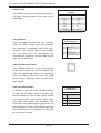
Overview ......................................................................................................... 1-1
1-2
Serverboard Features ..................................................................................... 1-2
Processor ........................................................................................................ 1-2
Memory ........................................................................................................... 1-2
Onboard SATA................................................................................................. 1-2
PCI Expansion Slots ....................................................................................... 1-2
Onboard Controllers/Ports .............................................................................. 1-2
Other Features ................................................................................................ 1-2
1-3
Server Chassis Features ................................................................................ 1-4
System Power ................................................................................................. 1-4
SATA Subsystem ............................................................................................. 1-4
Front Control Panel ......................................................................................... 1-4
I/O Backplane.................................................................................................. 1-4
Cooling System ............................................................................................... 1-4
Mounting Rails ................................................................................................ 1-5
1-4
Contacting Supermicro .................................................................................... 1-6
1-5
2U Twin2: System Notes ................................................................................. 1-7
Nodes .............................................................................................................. 1-7
System Power ................................................................................................. 1-7
SATA Backplane/Drives................................................................................... 1-7
Chapter 2 Server Installation
2-1
Overview ......................................................................................................... 2-1
2-2
Unpacking the System .................................................................................... 2-1
2-3
Preparing for Setup ......................................................................................... 2-1
Choosing a Setup Location ............................................................................. 2-1
Warnings and Precautions! ........................................................................................ 2-2
Rack Precautions ............................................................................................ 2-2
Server Precautions.......................................................................................... 2-2
Rack Mounting Considerations ....................................................................... 2-3
Ambient Operating Temperature ................................................................ 2-3
Reduced Airflow ......................................................................................... 2-3
Mechanical Loading ................................................................................... 2-3
Circuit Overloading ..................................................................................... 2-3
Reliable Ground ......................................................................................... 2-3
2-4
Installing the System into a Rack ................................................................... 2-4
v
Table of Contents
Separating the Sections of the Rack Rails ..................................................... 2-4
Installing the Inner Rail Extension .................................................................. 2-5
Outer Rack Rails ............................................................................................. 2-6
2-5
Checking the Serverboard Setup .................................................................... 2-8
2-6
Checking the Drive Bay Setup ...................................................................... 2-10
Chapter 3 System Interface
3-1
Overview ......................................................................................................... 3-1
4-2
Control Panel Button ....................................................................................... 3-2
4-3
Control Panel LEDs ........................................................................................ 3-2
4-4
Drive Carrier LEDs .......................................................................................... 3-3
SATA Drives .................................................................................................... 3-3
SCSI Drives..................................................................................................... 3-3
Chapter 4 System Safety
4-1
Electrical Safety Precautions .......................................................................... 4-1
4-2
General Safety Precautions ............................................................................ 4-2
4-3
ESD Precautions ............................................................................................. 4-3
4-4
Operating Precautions .................................................................................... 4-4
Chapter 5 Advanced Motherboard Setup
5-1
Handling the Motherboard .............................................................................. 5-1
Precautions ..................................................................................................... 5-1
Unpacking ....................................................................................................... 5-2
5-2
Motherboard Installation .................................................................................. 5-2
5-3
Connecting Cables .......................................................................................... 5-3
Connecting Data Cables ................................................................................. 5-3
Connecting Power Cables .............................................................................. 5-3
Connecting the Control Panel ......................................................................... 5-3
5-4
Rear I/O Ports ................................................................................................. 5-4
5-5
Processor and Heatsink Installation................................................................ 5-5
Installing a Passive CPU Heatsink ................................................................. 5-7
Removing the Heatsink ................................................................................... 5-7
5-6
Installing Memory ............................................................................................ 5-8
Memory Support .............................................................................................. 5-8
Maximum Memory ........................................................................................... 5-8
DIMM Module Population Configuration .................................................. 5-10
5-7
Adding PCI Expansion Cards ........................................................................5-11
5-8
Motherboard Details .......................................................................................5-11
H8DCT-IBQF/H8DCT-F Quick Reference ......................................................5-11
5-9
Connector Definitions ................................................................................... 5-14
vi
A+ SERVER 2022TC-BIBQRF/BTRF User's Manual
5-10
Jumper Settings ............................................................................................ 5-19
5-11
Onboard Indicators........................................................................................ 5-21
5-12
SATA Drive Connections ............................................................................... 5-22
5-13
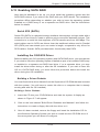
Enabling SATA RAID ..................................................................................... 5-23
Explanation of Jumpers ................................................................................ 5-19
Serial ATA (SATA).......................................................................................... 5-23
Installing the OS/SATA Driver ....................................................................... 5-23
Building a Driver Diskette ......................................................................... 5-23
Enabling SATA RAID in the BIOS ................................................................. 5-24
Using the Adaptec RAID Utility ..................................................................... 5-25
Installing the RAID Driver During OS Installation ......................................... 5-25
5-14
Installing Drivers............................................................................................ 5-26
Supero Doctor III ........................................................................................... 5-27
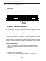
Chapter 6 Advanced Chassis Setup
6-1
Static-Sensitive Devices .................................................................................. 6-1
6-2
Control Panel .................................................................................................. 6-2
6-3
Chassis Cover ................................................................................................. 6-3
6-4
Air Guides ....................................................................................................... 6-4
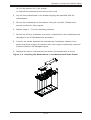
6-5
Checking the Airflow ....................................................................................... 6-4
Precautions ..................................................................................................... 6-1
Unpacking ....................................................................................................... 6-2
Installation Complete....................................................................................... 6-4
6-6
System Fans ................................................................................................... 6-5
6-7
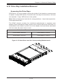
Removing and Installing the Backplane.......................................................... 6-7
Optional Fan Configurations ........................................................................... 6-5
Removing the Backplane ................................................................................ 6-7
Installing the Backplane .................................................................................. 6-9
6-8
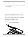
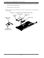
Installing the Motherboard ............................................................................ 6-10
I/O Shield ...................................................................................................... 6-10
Permanent and Optional Standoffs ............................................................... 6-10
6-9
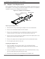
Adapter Card Replacement........................................................................... 6-12
Add-on Card/Expansion Slot Setup .............................................................. 6-13
6-10
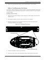
Drive Bay Installation/Removal ..................................................................... 6-15
6-11
Power Supply ................................................................................................ 6-19
Accessing the Drive Bays ............................................................................. 6-15
vii
Table of Contents
Power Supply Replacement .......................................................................... 6-19
Power Supply Replacement .......................................................................... 6-19
Chapter 7 BIOS
7-1
Introduction...................................................................................................... 7-1
Starting BIOS Setup Utility .............................................................................. 7-1
How To Change the Configuration Data ......................................................... 7-1
Starting the Setup Utility ................................................................................. 7-2
4-3
Advanced Settings Menu ................................................................................ 7-2
4-3
Security Menu ............................................................................................... 7-13
4-4
Boot Menu ..................................................................................................... 7-13
4-5
Exit Menu ...................................................................................................... 7-14
Appendix A BIOS Error Beep Codes
Appendix B System Specifications
viii
Chapter 1: Introduction
Chapter 1
Introduction
1-1
Overview
The A+ SERVER 2022TC-BIBQRF/BTRF is a high-end server comprised
of four main subsystems: the SC827H-R1400BP 2U server chassis and the
H8DCT-IBQF/H8DCT-F dual processor serverboard. Please refer to our web site for
information on operating systems that have been certified for use with the system
(www.supermicro.com).
In addition to the serverboard and chassis, various hardware components have
been included with the 2022TC-BIBQRF/BTRF, as listed below:
•
Four (4) 80x38-mm 4-pin Cooling fans (FAN-0111L4)
•
Four (4) 4-port Adapter cards for backplane (BPN-827ADP-X8)
•
One (1) SAS/SATA Backpane (BPN-SAS-827B)
•
Eight (8) Passive CPU heatsinks for AMD Socket F (SNK-P0022+)
•
Four (4) Riser Cards (RSC-R1U-E16R)
•
Twelve (12) Hard Disk Drive Trays (MCP-220-00075-0B)
•
One (1) Rack mount rail kit (MCP-290-00053-0N)
•
Four (4) 30-cm 16pin-to-16pin front control cables (CBL-0151L)
•
Four (4) Sets of SATA 3-17/20S-S/20S-RA-cm round cables (CBL-0317L)
•
Four (4) 5+18-cm 4-pin 1fan cables (CBL-0320L)
•
Four (4) 23-cm 4-pin to 4-pin I2C cables (CBL-0323L)
•
One CD containing manual, drivers and utilities
1-1
A+ SERVER 2022TC-BIBQRF/BTRF User's Manual
1-2
Serverboard Features
At the heart of the A+ Server 2022TC-BIBQRF/BTRF lies four H8DCT-IBQF/H8DCT-F
dual processor motherboards based upon one AMD SR5670 chipset and one SP5100
Southbridge chipset. Below are the main features of the H8DCT-IBQF/H8DCT-F.
Note that the features on each board are quadrupled for the server, which includes
four nodes.
Processor
Each H8DCT-IBQF/H8DCT-F supports up to two AMD® Opteron® 4100 series
(AMD Socket C32 type) processors. Please refer to our web site for a complete
listing of supported processors (www.supermicro.com).
Memory
Each H8DCT-IBQF/H8DCT-F serverboard has Twelve (12) dual channel DIMM slots that
can support up to 32 GB of ECC/Non-ECC UDIMM or up to 128 GB of ECC RDIMM
DDR3-1333/1066/800 in 1 GB, 2 GB, 4 GB, 8 GB or 16 GB sizes of 1.5V or 1.35V
voltages.
Onboard SATA
A SATA controller is built into the AMD SP5100 chipset to provide support for a four
port, 3 Gb/sec Serial ATA subsystem, which is RAID 0, 1 and 10 compatible.
PCI Expansion Slots
Each H8DCT-IBQF/H8DCT-F has one (1) PCI-Express x16 Gen. 2 slot.
Onboard Controllers/Ports
Onboard I/O backpanel ports include one COM port, a VGA port, two Gb LAN ports, a
dedicated IPMI LAN port, two USB ports and one single QSFP InfiniBand connector
(H8DCT-IBQF only). Two USB headers are included on the motherboard.
Other Features
Other onboard features that promote system health include voltage monitors, a
chassis intrusion header, auto-switching voltage regulators, chassis and CPU
overheat sensors and virus protection.
1-2
Chapter 1: Introduction
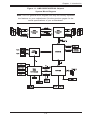
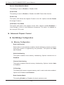
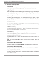
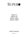
Figure 1-1. AMD SR5670/SP5100 Chipset:
System Block Diagram
Note: This is a general block diagram and may not exactly represent
the features on your motherboard. See the previous pages for the
actual specifications of your motherboard.
DDR3
1333/1066/800MT/s
CH B
DIMM A0
AMD
Socket C32
CPU1
CH A
DDR3
1333/1066/800MT/s
HT3 Link
16x16 bits 5.2GT/s
RJ45
INTEL
KAWELA
PCI-E GEN2 X4
SR5670
PCI-E GEN2 X16
Slot1
PCI-E GEN2 X8
Mellanox
ConnectX
RJ45
RMII
A-Link
VGA
PCI
DDR2 SDRAM
64Mb X16bit
PSU I2C
BMC
VGA
WPCM450-R
IPMB
SMBus
SP5100
SATA x4
LPC
COM1
HWM
W83795G
SPI Flash
SIO
W83527
FE PHY
RTL8201N
RJ45
1-3
USB x4
DIMM A2
DIMM A1
CH A
HT3 Link
16 x16 bits 6.4GT/s
DIMM B0
AMD
Socket C32
CPU2
DIMM B2
DIMM B1
DIMM B0
DIMM B1
DIMM B2
DIMM A0
DIMM A1
DIMM A2
HT3 Link
16 x16 bits 6.4GT/s
CH B
A+ SERVER 2022TC-BIBQRF/BTRF User's Manual
1-3
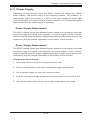
Server Chassis Features
The following is a general outline of the main features of the SC827 server
chassis.
System Power
Each SC827 chassis model includes a high-efficiency 80 Plus Gold certified power
supply, rated at 1400 Watts plus one redundant backup power supply. In the unlikely
event your power supply fails, replacement is simple and can be accomplished
without tools.
SATA Subsystem
The SC827 supports up to twelve 3.5" hot-swap SATA drives in trays (3 for each
node). These drives are hot-swappable units and are connected to a backplane
that provides power and control.
Note: The operating system you use must have RAID support to enable the hotswap capability of the drives.
Front Control Panel
SC827 models include four front panels on the handles of the chassis which control
each of the systems. Each control panel on the A+ SERVER 2022TC-BIBQRF/BTRF
provides you with system monitoring and control for one server node. LEDs indicate
system power, HDD activity, network activity, system overheat and power supply
failure. A main power button and a system reset button are also included.
I/O Backplane
The SC827 is an ATX form factor chassis designed to be used in a 2U rackmount
configuration. The SAS827B I/O backplane provides a low-profile add-on card slot,
a COM port, a VGA port, two USB 2.0 ports , one IPMI Ethernet port and two gigabit
Ethernet ports per node.
For more information regarding the backplane, view the appendices found at the
end of this manual.
Cooling System
The SC827 chassis accepts four system fans powered from either backpane or the
serverboards. If not powered from the backpane, the SC827B model chassis powers
two fans from two motherboards, so that when one of the motherboard drawers is
removed, the second motherboard will continue running both fans.
1-4
Chapter 1: Introduction
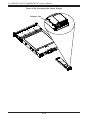
Mounting Rails
The SC827 includes a set of quick-release rails, and can be placed in a rack for
secure storage and use. To setup your rack, follow the step-by-step instructions
included in this manual.
1-5
A+ SERVER 2022TC-BIBQRF/BTRF User's Manual
1-4
Contacting Supermicro
Headquarters
Address:
Super Micro Computer, Inc.
980 Rock Ave.
San Jose, CA 95131 U.S.A.
Tel:
+1 (408) 503-8000
Fax:
+1 (408) 503-8008
Email:
[email protected] (General Information)
[email protected] (Technical Support)
Web Site:
www.supermicro.com
Europe
Address:
Super Micro Computer B.V.
Het Sterrenbeeld 28, 5215 ML
's-Hertogenbosch, The Netherlands
Tel:
+31 (0) 73-6400390
Fax:
+31 (0) 73-6416525
Email:
[email protected] (General Information)
[email protected] (Technical Support)
[email protected] (Customer Support)
Asia-Pacific
Address:
Super Micro Computer, Inc.
4F, No. 232-1, Liancheng Rd.
Chung-Ho 235, Taipei County
Taiwan, R.O.C.
Tel:
+886-(2) 8226-3990
Fax:
+886-(2) 8226-3991
Web Site:
www.supermicro.com.tw
Technical Support:
Email:
[email protected]
Tel:
886-2-8228-1366, ext.132 or 139
1-6
Chapter 1: Introduction
1-5
2U Twin2: System Notes
As a 2U Twin2 configuration, the 2022TC-BIBQRF/BTRF is a unique server system.
With four system boards incorporated into a single chassis acting as four separate
nodes, there are several points you should keep in mind.
Nodes
Each of the four serverboards act as a separate node in the system. As independant
nodes, each may be powered off and on without affecting the others. In addition,
each node is a hot-swappable unit that may be removed from the rear of the chassis.
The nodes are connected to the server backplane by means of an adapter card.
Note: A guide pin is located between the upper and lower nodes on the inner chassis
wall. This guide pin also acts as a “stop” when a node is fully installed. If too much
force is used when inserting a node this pin may break off. Take care to slowly slide
a node in until you hear the “click” of the locking tab seating itself.
System Power
A single 1400W power supply is used to provide the power for all four serverboards.
Each serverboard however, can be shut down independently of the other with the
power button on its own control panel. As an option, you may add an additional
1400W power supply module for power redundancy.
SATA Backplane/Drives
As a system, the 2022TC-BIBQRF/BTRF supports the use of twelve SATA drives.
A single SATA backplane works to apply system-based control for power and fan
speed functions, yet at the same time logically connects a set of three SATA drives
to each serverboard. Consequently, RAID setup is limited to a three-drive scheme
(RAID cannot be spread across all twelve drives). See the Drive Bay Installation/
Removal section in Chapter 6 for the logical hard drive and node configuration.
1-7
A+ SERVER 2022TC-BIBQRF/BTRF User's Manual
Notes
1-8
Chapter 2: Server Installation
Chapter 2
Server Installation
2-1
Overview
This chapter provides a quick setup checklist to get your A+ SERVER
2022TC-BIBQRF/BTRF up and running. Following these steps in the order given
should enable you to have the system operational within a minimum amount of time.
This quick setup assumes that your system has come to you with the processors
and memory preinstalled. If your system is not already fully integrated with a
serverboard, processors, system memory etc., please turn to the chapter or section
noted in each step for details on installing specific components.
2-2
Unpacking the System
You should inspect the box the A+ SERVER 2022TC-BIBQRF/BTRF was shipped
in and note if it was damaged in any way. If the server itself shows damage you
should file a damage claim with the carrier who delivered it.
Decide on a suitable location for the rack unit that will hold the A+ SERVER
2022TC-BIBQRF/BTRF. It should be situated in a clean, dust-free area that is well
ventilated. Avoid areas where heat, electrical noise and electromagnetic fields are
generated. You will also need it placed near a grounded power outlet. Read the
Rack and Server Precautions in the next section.
2-3
Preparing for Setup
The box the A+ SERVER 2022TC-BIBQRF/BTRF was shipped in should include
two sets of rail assemblies, two rail mounting brackets and the mounting screws
you will need to install the system into the rack. Follow the steps in the order
given to complete the installation process in a minimum amount of time. Please
read this section in its entirety before you begin the installation procedure outlined
in the sections that follow.
Choosing a Setup Location
•
Leave enough clearance in front of the rack to enable you to open the front door
completely (~25 inches) and approximately 30 inches of clearance in the back
of the rack to allow for sufficient airflow and ease in servicing.
2-1
A+ SERVER 2022TC-BIBQRF/BTRF User's Manual
•
•
This product is for installation only in a Restricted Access Location (dedicated
equipment rooms, service closets and the like).
This product is not suitable for use with visual display work place devices
acccording to §2 of the the German Ordinance for Work with Visual Display
Units.
!
Warnings and Precautions!
!
Rack Precautions
•
•
•
•
Ensure that the leveling jacks on the bottom of the rack are fully extended to
the floor with the full weight of the rack resting on them.
In single rack installation, stabilizers should be attached to the rack. In multiple
rack installations, the racks should be coupled together.
Always make sure the rack is stable before extending a component from the
rack.
You should extend only one component at a time - extending two or more simultaneously may cause the rack to become unstable.
Server Precautions
•
•
•
•
•
•
Review the electrical and general safety precautions in Chapter 4.
Determine the placement of each component in the rack before you install the
rails.
Install the heaviest server components on the bottom of the rack first, and then
work up.
Use a regulating uninterruptible power supply (UPS) to protect the server from
power surges, voltage spikes and to keep your system operating in case of a
power failure.
Allow any hot plug drives and power supply modules to cool before touching
them.
Always keep the rack's front door and all panels and components on the servers
closed when not servicing to maintain proper cooling.
2-2
Chapter 2: Server Installation
Rack Mounting Considerations
Ambient Operating Temperature
If installed in a closed or multi-unit rack assembly, the ambient operating
temperature of the rack environment may be greater than the ambient temperature
of the room. Therefore, consideration should be given to installing the equipment
in an environment compatible with the manufacturer’s maximum rated ambient
temperature (Tmra).
Reduced Airflow
Equipment should be mounted into a rack so that the amount of airflow required
for safe operation is not compromised.
Mechanical Loading
Equipment should be mounted into a rack so that a hazardous condition does not
arise due to uneven mechanical loading.
Circuit Overloading
Consideration should be given to the connection of the equipment to the power
supply circuitry and the effect that any possible overloading of circuits might have
on overcurrent protection and power supply wiring. Appropriate consideration of
equipment nameplate ratings should be used when addressing this concern.
Reliable Ground
A reliable ground must be maintained at all times. To ensure this, the rack
itself should be grounded. Particular attention should be given to power supply
connections other than the direct connections to the branch circuit (i.e. the use of
power strips, etc.).
2-3
A+ SERVER 2022TC-BIBQRF/BTRF User's Manual
2-4
Installing the System into a Rack
This section provides information on installing the SC827 chassis into a rack unit
with the quick-release rails provided. There are a variety of rack units on the market,
which may mean the assembly procedure will differ slightly. You should also refer to
the installation instructions that came with the rack unit you are using.
NOTE: This rail will fit a rack between 26" and 33.5" deep.
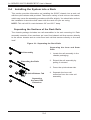
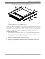
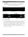
Separating the Sections of the Rack Rails
The chassis package includes two rail assemblies in the rack mounting kit. Each
assembly consists of two sections: an inner fixed chassis rail that secures directly
to the server chassis and an outer fixed rack rail that secures directly to the rack
itself.
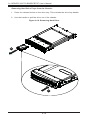
Figure 2-1: Separating the Rack Rails
Separating the Inner and Outer
Rails
Rail Assembly
1
1. Locate the rail assembly in the
chassis packaging.
2. Extend the rail assembly by
pulling it outward.
Extending the Rails
12
3. Press the quick-release tab.
13
14
Quick-Release Tab
Separating
the Inner Rail
Extension
2-4
4. Separate the inner rail
extension from the outer rail
assembly.
Chapter 2: Server Installation
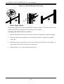
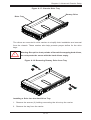
Figure 2-2: Installing the Inner Rail Extensions
13
12
13
1
Installing the Inner Rail Extension
The SC827 chassis includes a set of inner rails in two sections: inner rails and inner
rail extensions. The inner rails are pre-attached to the chassis, and do not interfere
with normal use of the chassis if you decide not to use a server rack. The inner rail
extension is attached to the inner rail to mount the chassis in the rack.
Installing the Inner Rails
1. Place the inner rail extensions on the side of the chassis aligning the hooks
of the chassis with the rail extension holes. Make sure the extension faces
"outward" just like the pre-attached inner rail.
2. Slide the extension toward the front of the chassis.
3. Secure the chassis with 2 screws as illustrated. Repeat steps for the other
inner rail extension.
2-5
A+ SERVER 2022TC-BIBQRF/BTRF User's Manual
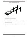
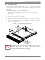
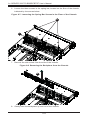
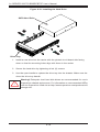
Figure 2-3. Assembling the Outer Rails
12
1
13
Outer Rack Rails
Outer rails attach to the rack and hold the chassis in place. The outer rails for the
SC827 chassis extend between 30 inches and 33 inches.
Installing the Outer Rails to the Rack
1. Secure the back end of the outer rail to the rack, using the screws provided.
2. Press the button where the two outer rails are joined to retract the smaller
outer rail.
3. Hang the hooks of the rails onto the rack holes and if desired, use screws to
secure the front of the outer rail onto the rack.
4. Repeat steps 1-3 for the remaining outer rail.
2-6
Chapter 2: Server Installation
Figure 2-4: Installing the Rack Rails
Installing the Chassis into a Rack
1. Extend the outer rails as illustrated above.
2. Align the inner rails of the chassis with the outer rails on the rack.
3. Slide the inner rails into the outer rails, keeping the pressure even on both
sides. When the chassis has been pushed completely into the rack, it should
click into the locked position.
4. Optional screws may be used to secure the to hold the front of the chassis to
the rack.
2-7
A+ SERVER 2022TC-BIBQRF/BTRF User's Manual
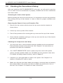
2-5
Checking the Serverboard Setup
After you install the 2022TC-BIBQRF/BTRF in the rack, you will need to open the
unit to make sure the serverboard is properly installed and all the connections
have been made.
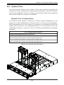
Accessing the inside of the System
Before operating the server for the first time, it is important to remove the protective
film covering the top of the chassis, in order to allow for proper ventilation and
cooling.
Removing the Chassis Cover and Protective Film
1. Remove the two screws which secure the top cover onto the chassis as
shown above.
2. Lift the top cover up and off the chassis.
3. Peel off the protective film covering the top cover and the top of the chassis
4. Check that all ventilation openings on the top cover and the top of the chassis
are clear and unobstructed.
Checking the Components and Setup
1. You may have one or two processors already installed into the serverboard.
Each processor needs its own heat sink. See Chapter 5 for instructions on
processor and heat sink installation.
2. Your 2022TC-BIBQRF/BTRF server system may have come with system
memory already installed. Make sure all DIMMs are fully seated in their slots.
For details on adding system memory, refer to Chapter 5.
3. If desired, you can install add-on cards to the system. See Chapter 5 for
details on installing PCI add-on cards.
4. Make sure all power and data cables are properly connected and not blocking
the chassis airflow. Also make sure that no cables are positioned in front of
the fans. See Chapter 5 for details on cable connections.
2-8
Chapter 2: Server Installation
Figure 2-5. Accessing the Inside of the System
1
Remove two
screws
12
13
Check Ventilation
Openings
14
2-9
A+ SERVER 2022TC-BIBQRF/BTRF User's Manual
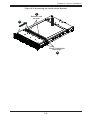
2-6
Checking the Drive Bay Setup
Next, you should check to make sure the peripheral drives and the SATA drives
have been properly installed and all connections have been made.
Checking the Drives
1. All drives are accessable from the front of the server. A hard drive can be
installed and removed from the front of the chassis without removing the top
chassis cover.
2. Depending upon your system's configuration, your system may have one or
more drives already installed. If you need to install hard drives, please refer to
Chapter 6.
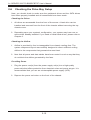
Checking the Airflow
1. Airflow is provided by four hot-swappable 8-cm chassis cooling fans. The
system component layout was carefully designed to direct sufficient cooling
airflow to the components that generate the most heat.
2. Note that all power and data cables have been routed in such a way that they
do not block the airflow generated by the fans.
Providing Power
1. Plug the power cord(s) from the power supply unit(s) into a high-quality
power strip that offers protection from electrical noise and power surges. It is
recommended that you use an uninterruptible power supply (UPS).
2. Depress the power on button on the front of the chassis.
2-10
Chapter 3: System Interface
Chapter 3
System Interface
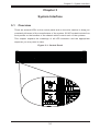
3-1
Overview
There are several LEDs on the control panel and on the drive carriers to keep you
constantly informed of the overall status of the system. SC827 models include four
front panels on the handles of the chassis which control each of the systems.
This chapter explains the meanings of all LED indicators and the appropriate
response you may need to take.
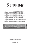
Figure 3-1: Control Panel
3-1
A+ SERVER 2022TC-BIBQRF/BTRF User's Manual
4-2
•
4-3
Control Panel Button
Power: The main power button on each of the four control panels is used to
apply or remove power from the power supply to each of the four systems in
the chassis. Turning off system power with this button removes the main power,
but keeps standby power supplied to the system. Therefore, you must unplug
system before servicing.
Control Panel LEDs
The four control panels are located on the front handle of the SC827 chassis. Each
control panel has three LEDs. These LEDs provide you with critical information
related to different parts of the system. This section explains what each LED
indicates when illuminated and any corrective action you may need to take.
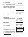
•
•
Overheat: This LED is illuminated when an overheat condition occurs.
A solid red LED indicates an overheat condition in the system.
A flashing red LED which flashes in one second intervals indicates a fan failure.
A flashing red LED which flashes in four second interfals indicates a power
failure. Check the routing of the cables and make sure all fans are present and
operating normally. You should also check to make sure that the chassis covers and air shrouds are installed. Finally, verify that the heatsinks are installed
properly. This LED will remain flashing or on as long as the temperature is too
high or a fan does not function properly.
NIC1: Indicates network activity on GLAN1 when flashing.
3-2
Chapter 3: System Interface
4-4
Drive Carrier LEDs
The server chassis uses SATA drives.
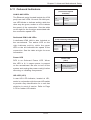
SATA Drives
Each SATA drive carrier has two LEDs.
•
•
Green: Each Serial ATA drive carrier has a green LED. When illuminated, this
green LED (on the front of the SATA drive carrier) indicates drive activity. A connection to the SATA backplane enables this LED to blink on and off when that
particular drive is being accessed.
Red: The red LED to indicate an SATA drive failure. If one of the SATA drives
fail, you should be notified by your system management software.
SCSI Drives
This chassis does not support SCSI drives at this time.
3-3
A+ SERVER 2022TC-BIBQRF/BTRF User's Manual
Notes
3-4
Chapter 4: System Safety
Chapter 4
System Safety
4-1
Electrical Safety Precautions
!
Basic electrical safety precautions should be followed to protect yourself from harm
and the A+ SERVER 2022TC-BIBQRF/BTRF from damage:
•
•
•
•
•
Be aware of the locations of the power on/off switch on the chassis as well
as the room's emergency power-off switch, disconnection switch or electrical
outlet. If an electrical accident occurs, you can then quickly remove power from
the system.
Do not work alone when working with high voltage components.
Power should always be disconnected from the system when removing or installing main system components, such as the serverboard, memory modules
and add-on cards. When disconnecting power, you should first power down the
operating system first and then unplug the power cords. The unit has more than
one power supply cord. Disconnect two power supply cords before servicing to
avoid electrical shock.
When working around exposed electrical circuits, another person who is familiar
with the power-off controls should be nearby to switch off the power if necessary.
Use only one hand when working with powered-on electrical equipment. This
is to avoid making a complete circuit, which will cause electrical shock. Use
extreme caution when using metal tools, which can easily damage any electrical
components or circuit boards they come into contact with.
•
Do not use mats designed to decrease static electrical discharge as protection
from electrical shock. Instead, use rubber mats that have been specifically
designed as electrical insulators.
4-1
A+ SERVER 2022TC-BIBQRF/BTRF User's Manual
•
•
•
•
4-2
The power supply power cords must include a grounding plug and must be
plugged into grounded electrical outlets.
This product may be connected to an IT power system. In all cases, make sure
that the unit is also reliably connected to Earth (ground).
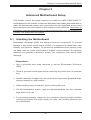
Serverboard Battery: CAUTION - There is a danger of explosion if the onboard
CR2032 battery is installed upside down, which will reverse its polarites (see
Figure 4-1). This battery must be replaced only with the same or an equivalent
type recommended by the manufacturer. Dispose of used batteries according
to the manufacturer's instructions.
Mainboard replaceable soldered-in fuses: Self-resetting PTC (Positive Temperature Coefficient) fuses on the mainboard must be replaced by trained service
technicians only. The new fuse must be the same or equivalent as the one
replaced. Contact technical support for details and support.
General Safety Precautions
!
Follow these rules to ensure general safety:
•
•
•
•
•
Keep the area around the 2022TC-BIBQRF/BTRF clean and free of clutter.
The 2022TC-BIBQRF/BTRF weighs approximately 85 lbs (38.6kg) when fully
loaded. When lifting the system, two people at either end should lift slowly with
their feet spread out to distribute the weight. Always keep your back straight
and lift with your legs.
Place the chassis top cover and any system components that have been removed away from the system or on a table so that they won't accidentally be
stepped on.
While working on the system, do not wear loose clothing such as neckties and
unbuttoned shirt sleeves, which can come into contact with electrical circuits or
be pulled into a cooling fan.
Remove any jewelry or metal objects from your body, which are excellent metal
conductors that can create short circuits and harm you if they come into contact
with printed circuit boards or areas where power is present.
4-2
Chapter 4: System Safety
•
4-3
After accessing the inside of the system, close the system back up and secure
it to the rack unit with the retention screws after ensuring that all connections
have been made.
ESD Precautions
!
Electrostatic discharge (ESD) is generated by two objects with different electrical
charges coming into contact with each other. An electrical discharge is created to
neutralize this difference, which can damage electronic components and printed
circuit boards. The following measures are generally sufficient to neutralize this
difference before contact is made to protect your equipment from ESD:
•
•
•
•
•
•
•
•
Use a grounded wrist strap designed to prevent static discharge.
Keep all components and printed circuit boards (PCBs) in their antistatic bags
until ready for use.
Touch a grounded metal object before removing the board from the antistatic
bag.
Do not let components or PCBs come into contact with your clothing, which may
retain a charge even if you are wearing a wrist strap.
Handle a board by its edges only; do not touch its components, peripheral chips,
memory modules or contacts.
When handling chips or modules, avoid touching their pins.
Put the serverboard and peripherals back into their antistatic bags when not
in use.
For grounding purposes, make sure your computer chassis provides excellent
conductivity between the power supply, the case, the mounting fasteners and
the serverboard.
4-3
A+ SERVER 2022TC-BIBQRF/BTRF User's Manual
4-4
Operating Precautions
Care must be taken to assure that the chassis cover is in place when
the 2022TC-BIBQRF/BTRF is operating to assure proper cooling. Out of
warranty damage to the system can occur if this practice is not strictly
followed.
!
Figure 4-1. Installing the Onboard CR2032 Battery
LITHIUM BATTERY
BATTERY HOLDER
!
Please handle used batteries carefully. Do not damage the battery in any
way; a damaged battery may release hazardous materials into the environment. Do not discard a used battery in the garbage or a public landfill.
Please comply with the regulations set up by your local hazardous waste
management agency to dispose of your used battery properly.
4-4
Chapter 5: Advanced Motherboard Setup
Chapter 5
Advanced Motherboard Setup
This chapter covers the steps required to install the H8DCT-IBQF/H8DCT-F
motherboard into the chassis, connect the data and power cables and install add-on
cards. All motherboard jumpers and connections are also described. A layout and
quick reference chart are included in this chapter for your reference. Remember to
completely close the chassis when you have finished working with the motherboard
to better cool and protect the system.
5-1
Handling the Motherboard
Electrostatic Discharge (ESD) can damage electronic components. To prevent
damage to any printed circuit boards (PCBs), it is important to handle them very
carefully (see previous chapter). To prevent the motherboard from bending, keep
one hand under the center of the board to support it when handling. The following
measures are generally sufficient to protect your equipment from electric static
discharge.
Precautions
•
•
Use a grounded wrist strap designed to prevent Electrostatic Discharge
(ESD).
Touch a grounded metal object before removing any board from its antistatic
bag.
•
•
•
•
Handle a board by its edges only; do not touch its components, peripheral chips,
memory modules or gold contacts.
When handling chips or modules, avoid touching their pins.
Put the motherboard, add-on cards and peripherals back into their antistatic
bags when not in use.
For grounding purposes, make sure your computer chassis provides excellent
conductivity between the power supply, the case, the mounting fasteners and
the motherboard.
5-1
A+ Server 2022TC-BIBQRF/BTRF User's Manual
Unpacking
The motherboard is shipped in antistatic packaging to avoid electrical static
discharge. When unpacking the board, make sure the person handling it is static
protected.
5-2
Motherboard Installation
This section explains the first step of physically mounting the H8DCT-IBQF/H8DCT-F
into the SC827H-R1400BP chassis. Following the steps in the order given will eliminate the most common problems encountered in such an installation. To remove
the motherboard, follow the procedure in reverse order.
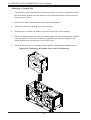
Installing to the Chassis
1. Access the inside of the system by removing the screws from the top cover of
the chassis, then lift the cover off.
2. Make sure that the I/O ports on the motherboard align properly with their
respective holes in the I/O shield at the back of the chassis.
3. Carefully mount the motherboard to the motherboard tray by aligning the
board holes with the raised metal standoffs that are visible in the chassis.
4. Insert screws into all the mounting holes on your motherboard that line up
with the standoffs and tighten until snug (if you screw them in too tight, you
might strip the threads). Metal screws provide an electrical contact to the
motherboard ground to provide a continuous ground for the system.
5. Finish by replacing the top cover of the chassis.
Warning: To avoid damaging the motherboard and its components, do not apply any
force greater than 8 lbs. per square inch when installing a screw into a mounting
hole.
5-2
Chapter 5: Advanced Motherboard Setup
5-3
Connecting Cables
Now that the motherboard is installed, the next step is to connect the cables to
the board. These include the data cables for the peripherals and control panel and
the power cables.
Connecting Data Cables
The cables used to transfer data from the peripheral devices have been carefully
routed to prevent them from blocking the flow of cooling air that moves through
the system from front to back. If you need to disconnect any of these cables, you
should take care to keep them routed as they were originally after reconnecting
them (make sure the red wires connect to the pin 1 locations). The following data
cables (with their locations noted) should be connected. (See the motherboard
layout for connector locations.)
•
Control Panel cable (JF1)
•
SATA Port Cables (SATA0 ~ SATA3)
Connecting Power Cables
The H8DCT-IBQF/H8DCT-F has two 20-pin main proprietary power supply
connectors (JPW1 and JPW2) for connection to the ATX power supply. Only one
of these from each board should be connected to the power supply.
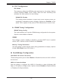
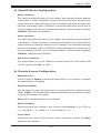
Connecting the Control Panel
JF1 contains header pins for various front control panel connectors. See Figure 5-1
for the pin locations of the various front control panel buttons and LED indicators.
All JF1 wires have been bundled into a single cable to simplify this connection. Make
sure the red wire plugs into pin 1 as marked on the board. The other end connects
to the Control Panel PCB board, located just behind the system status LEDs on
the chassis. See Chapter 5 for details and pin descriptions.
5-3
A+ Server 2022TC-BIBQRF/BTRF User's Manual
Figure 5-1. Control Panel Header Pins
20 19
Ground
No Connection
Key
Key
Power LED
3.3V
FP UID Switch/3.3VSB
HDD LED
NIC1 (Link) LED
NIC1 (Activity) LED
NIC2 (Link) LED
NIC2 (Activity) LED
Blue_LED_Cathode (UID)/5V SB
OH/Fan Fail/PWR Fail/UID LED
3.3V
Power Fail LED
Reset Button
Ground
Ground
Power Button
2
5-4
1
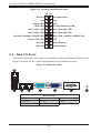
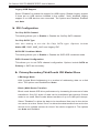
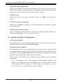
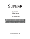
Rear I/O Ports
The rear I/O ports are color coded in conformance with the PC 99 specification. See
Figure 5-2 below for the colors and locations of the various I/O ports.
Figure 5-2. Rear I/O Ports
2
1
3
4
5
6
7
Rear I/O Ports
1. USB0/1
4. LAN2
7. InfiniBand Port
2. IPMI LAN
5. COM1
8. UID
3. LAN1
6. VGA Port
5-4
8
Chapter 5: Advanced Motherboard Setup
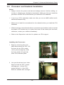
5-5
Processor and Heatsink Installation
Notes:
Always connect the power cord last and always remove it before adding, re-
•
moving or changing any hardware components. Make sure that you install the
processor into the CPU socket before you install the CPU heatsink.
•
•
•
•
If you buy a CPU separately, make sure that you use an AMD-certified multidirectional heatsink only.
Make sure to install the serverboard into the chassis before you install the CPU
heatsinks.
When receiving a serverboard without a processor pre-installed, make sure that
the plastic CPU socket cap is in place and none of the socket pins are bent;
otherwise, contact your retailer immediately.
Refer to the Supermicro web site for updates on CPU support.
Installing the Processors
1. Begin by removing the cover
plate that protects the CPU. Lift
the lever on the CPU socket
until it points straight up. With
the lever raised, lift open the
silver CPU retention plate.
Triangles
2. Use your thumb and your index
finger to hold the CPU. Locate
and align pin 1 of the CPU
socket with pin 1 of the CPU.
Both are marked with a triangle.
5-5
A+ Server 2022TC-BIBQRF/BTRF User's Manual
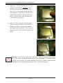
3. Align pin 1 of the CPU with pin 1 of the
socket. Once aligned, carefully place
the CPU into the socket. Do not drop
the CPU on the socket, move the CPU
horizontally or vertically or rub the CPU
against the socket or against any pins
of the socket, which may damage the
CPU and/or the socket.
4. With the CPU inserted into the socket,
inspect the four corners of the CPU to
make sure that it is properly installed
and flush with the socket. Then, gently
lower the silver CPU retention plate into
place.
!
Warning: The CPU will only seat inside the socket in one direction. Make
sure it is properly inserted before closing the load plate. If it doesn't close
properly, do not force it as it may damage your CPU. Instead, open the load
plate again and double-check that the CPU is aligned properly.
5-6
Chapter 5: Advanced Motherboard Setup
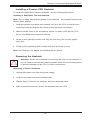
Installing a Passive CPU Heatsink
To install the SNK-0022+ Passive Heatsink, use the following procedure:
Installing a SNK-0022+ Passive Heatsink
Note: Do not apply any thermal grease to the heatsink - the required amount has
already been applied.
1. Hold the heatsink and place the heatsink on top of the CPU so that the two
mounting holes are aligned with those on the retension mechanism.
2. Make sure the force of the screwdriver torsion is under 6.025 kgf-cm (5.23
lbs-in), and keep screw direction vertical.
3. Screw in two opposite screws until they are just snug (do not fully tighten
them yet).
4. Finish by fully tightening both screws after they are both in snug.
Note: see Chapter 6 for details on installing the air shroud.
Removing the Heatsink
!
Warning: We do not recommend removing the CPU or the heatsink. If
you do need to remove the heatsink, please follow the instructions below
to prevent damage to the CPU or other components.
Removing a Passive Heatsink
1. Unplug the power cord from the power supply.
2. Loosen all screws from the mounting holes.
3. Repeat Step 2 to loosen all fasteners from the mounting holes.
4. With all screws loosened, remove the heatsink from the CPU.
5-7
A+ Server 2022TC-BIBQRF/BTRF User's Manual
5-6
Installing Memory
Installing Memory
1. Insert each memory module vertically into its slot, paying attention to the
notch along the bottom of the module to prevent inserting the module
incorrectly (see Figure 5-3).
2. Install to slots P1/DIMM1A, P1/DIMM2A, etc. For best performance always
install in groups of two and in the numerical order of the DIMM slots. See
support information below.
3. Gently press down on the memory module until it snaps into place.
4. With two CPUs installed, repeat step 2 to populate the CPU2 DIMM slots. For
best performance always install in groups of two and in the numerical order of
the DIMM slots.
Note: 1 GB, 2 GB, 4 GB, 8 GB and 16 GB memory modules are supported. It
is highly recommended that you remove the power cord from the system before
installing or changing memory modules. Please refer to our web site for memory
that has been tested on the H8DCT-IBQF/H8DCT-F serverboard.
Memory Support
The H8DCT-IBQF/ H8DCT-F serverboard supports single and dual channel,
DDR3-1333/1066/800 registered ECC/Unbuffered ECC/non-ECC SDRAM.
Populating two slots at a time with memory modules of the same size and type will
result in interleaved (128-bit) memory, which is faster than non-interleaved (64-bit)
memory.”
Maximum Memory
The H8DCT-IBQF/H8DCT-F serverboard supports up to 32 GB of ECC/Non-ECC
UDIMM or up to 128 GB of ECC RDIMM in 12 DIMM slots.
5-8
Chapter 5: Advanced Motherboard Setup
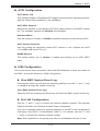
Figure 5-3. Installing DIMM into Slot
To Install: Insert
module vertically and
press down until it
snaps into place. Pay
attention to the alignment notch at the
bottom.
Notch
Notch
Front View
Note: Notch should align with
the receptive key point on
the slot.
To Remove: Use
your thumbs to gen- Release Tab
tly push the release
tabs near both ends
of the module. This
should release it from
the slot.
Release Tab
Top View of DDR3 Slot
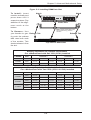
Memory Population for Optimal Performance
-For a Motherboard with One CPU (CPU1) Installed
# DIMMS
CPU
2 DIMMs
CPU1
P1-1A
Channel 1
4 DIMMs
CPU1
P1-1A
6 DIMMs
CPU1
P1-1A
Channel 2
P1-2A
P1-1B
P1-1C
P1-2A
P1-1C
P1-2A
P1-2C
P1-2B
P1-2C
Memory Population for Optimal Performance
-For a Motherboard with Two CPUs (CPU1 & CPU2) Installed
# DIMMS
CPU
Channel 1
Channel 2
CPU1
P1-1A
P1-2A
CPU2
P2-1A
CPU1
P1-1A
P1-1C
P1-2A
CPU2
P2-1A
P2-1C
P2-2A
CPU1
P1-1A
P1-1B
P1-1C
P1-2A
P1-2B
P1-2C
CPU2
P2-1A
P2-1B
P2-1C
P2-2A
P2-2B
P2-2C
4 DIMMs
P2-2A
P1-2C
8 DIMMs
P2-2C
12 DIMMs
5-9
A+ Server 2022TC-BIBQRF/BTRF User's Manual
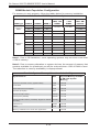
DIMM Module Population Configuration
For memory to work properly, follow the tables below for memory installation:
Per Channel DIMM Populations Options
DIMM Type
DIMM A
DIMM B
DIMM C
SR or DR
Empty
Empty
SR
Empty
SR
Unbuffered
DIMM
Max.
MHz, 1.5V
DIMMs
Max. MHz,
1.35V
DIMMs
1333 MHz
1333 MHz
Max. GB/
Channel
4 GB
4 GB
DR
Empty
DR
1066 MHz
1066 MHz
SR or DR
Empty
Empty
1333 MHz
1333 MHz
8 GB
SR
Empty
SR
1333 MHz
1333 MHz
8 GB
Registered
DIMM
8 GB
SR
SR
SR
1066 MHz
800 MHz
12 GB
DR
Empty
DR
1066 MHz
1066 MHz
16 GB
Empty
QR
Empty
800 MHz
800 MHz
16 GB
DR
DR
DR
800 MHz
800 MHz
24 GB
SR or DR
QR
Empty
800 MHz
667 MHz
24 GB
SR or DR
QR
SR or DR
667 MHz
667 MHz
32 GB
Note 1: Due to OS limitations, some operating systems may not show more than
4 GB of memory.
Note 2: Due to memory allocation to system devices, the amount of memory that
remains available for operational use will be reduced when 4 GB of RAM is used.
The reduction in memory availability is disproportional.
Possible System Memory Allocation & Availability
System Device
Size
Physical Memory Available
(4 GB Total System
Memory)
Firmware Hub flash memory (System BIOS)
1 MB
3.99 GB
Local APIC
4 KB
3.99 GB
Area Reserved for the chipset
2 MB
3.99 GB
I/O APIC (4 Kbytes)
4 KB
3.99 GB
PCI Enumeration Area 1
256 MB
3.76 GB
PCI Express (256 MB)
256 MB
3.51 GB
PCI Enumeration Area 2 (if needed) -Aligned on 256-M
boundary-
512 MB
3.01 GB
VGA Memory
16 MB
2.85 GB
TSEG
1 MB
2.84 GB
Memory available for the OS & other applications
5-10
2.84 GB
Chapter 5: Advanced Motherboard Setup
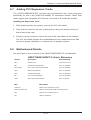
5-7
Adding PCI Expansion Cards
The 2022TC-BIBQRF/BTRF includes two preinstalled riser cards designed
specifically for use in the SC827H-R1400BP 1U rackmount chassis. These riser
cards support two low-profile PCI Express x16 cards to fit inside the chassis.
Installing an Expansion Card
1. After powering down the system, remove the PCI slot shield.
2. Fully seat the card into the slot, pushing down with your thumbs evenly on
both sides of the card.
3. Finish by using a screw to secure the top of the card shield to the chassis.
The PCI slot shield protects the motherboard and its components from EMI
and aid in proper ventilation, so make sure it is always in place.
5-8
Motherboard Details
See the Figure 5-4 for a layout of the H8DCT-IBQF/H8DCT-F motherboard.
H8DCT-IBQF/H8DCT-F Quick Reference
Jumper
Description
JBT1
CMOS Clear
(See Section 5-10)
JIB1
InfiniBand Enable/Disable
Pins 1-2 (Enabled)
JI2C1/JI2C2
I2C to PCI-E Slot Enable/Disable
Pins 1-2 (Enabled)
JPB1
BMC Enable/Disable
Pins 1-2 (Enabled)
JPG1
VGA Enable/Disable
Pins 1-2 (Enabled)
JPL1
LAN 1/2 Enable/Disable
Pins 1-2 (Enabled)
JWD1
Watch Dog Enable/Disable
Pins 1-2 (Reset)
LED
Default Setting
Description
LAN Ports
LEDs for the LAN Ethernet ports
Dedicated IPMI LAN
LEDs for the dedicated IPMI LAN Ethernet port
DP2
LED for Serverboard Power-On
LE1
LED for UID Button
5-11
A+ Server 2022TC-BIBQRF/BTRF User's Manual
Connector
Description
COM1
COM1 Serial Port/Header
FAN 1-3
Chassis/CPU Fan Headers
IPMB
System Management Bus Header (SMBus)
IPMI LAN
Dedicated IPMI LAN Port
J163
Auxiliary Power Connector
JB2
InfiniBand Connector
JF1
Front Panel Connector
JL1
Chassis Intrusion Header
JOH1
Overheat Warning Header
JPI2C1
Power I2C Header
JTPM1
Trusted Platform Module Header
JPW1/JPW2
20-Pin Proprietary Power Connectors
LAN1/2
Gigabit Ethernet (RJ45) Ports
SATA0 ~ SATA3
SATA Ports
T-SGPIO-1
Serial General Purpose Input/Output Header for SATA
UID
Unit Identifier Button
USB0/1, USB2/3
Universal Serial Bus (USB) Ports, Headers and Type-A Port
VGA
VGA Connector
5-12
Chapter 5: Advanced Motherboard Setup
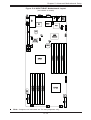
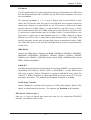
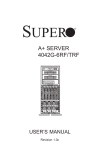
Figure 5-4. H8DCT-IBQF Motherboard Layout
(not drawn to scale)
UID
IB
BMC
LAN2
JIB1
JI2C2
JOH1
IPMB
JPB1
JI2C1
JB2
IPMI_LAN
USB0/1
COM1
LAN1
VGA
LE1
Speaker
DP2
USB2/3
PCI-Express x16 Gen. 2
JWD1
JTPM1
JPL1
NIC
AMD
SR5670
JPG1
JL1
AMD
SP5100
JBT1
T-SGPIO1
SATA0
SATA1
Battery
SATA2
SATA3
P1-DIMM1B
P1-DIMM1A
P1-DIMM1C
P1-DIMM2B
P1-DIMM2A
P1-DIMM2C
CPU1
JF1
P2-DIMM2B
P2-DIMM2C
P2-DIMM2A
P2-DIMM1B
P2-DIMM1C
J163
P2-DIMM1A
CPU2
JPI2C1
JPW2
JPW1
FAN3
FAN2
FAN1
Note: Jumpers not indicated are for test purposes only.
5-13
A+ Server 2022TC-BIBQRF/BTRF User's Manual
5-9
Connector Definitions
Proprietary 20-pin Connector
Pin Definitions
Power Connectors
The proprietary power supply connector
(JPW1 and JPW2) meets the SSI (Superset
ATX) 20-pin specification. Refer to the table
below for the pin definitions of the ATX 20-pin
power connector. This connection supplies
power to the chipset, fans and memory.
Auxiliary Power Connector
A 4-pin 12V auxiliary power connector
(J163) is included to provide power to hard
drive disks. See the table below for pin
definitions.
PW_ON Connector
The PW_ON connector is on pins 1 and 2 of
JF1. This header should be connected to the
chassis power button. See the table on the
right for pin definitions.
Reset Connector
The reset connector is located on pins 3 and
4 of JF1 and attaches to the reset switch on
the computer chassis. See the table on the
right for pin definitions.
5-14
Pin# Definition
Pin # Definition
1
GND
11
PS_ON_N
2
GND
12
5V_STBY
3
GND
13
GND
4
GND
14
GND
5
GND
15
GND
6
NC
16
NC
7
12V
17
12V
8
12V
18
12V
9
12V
19
12V
10
12V
20
12V
12V 4-pin PWR
Connector
Pin Definitions
Pin
Definition
1
+12V
2
Ground
3
Ground
4
+5V
Power Button
Pin Definitions
(JF1)
Pin# Definition
1
PW_ON
2
Ground
Reset Button
Pin Definitions
(JF1)
Pin# Definition
3
Reset
4
Ground
Chapter 5: Advanced Motherboard Setup
Overheat/Fan Fail LED (OH)
Connect an LED to the OH connection on
pins 7 and 8 of JF1 to provide advanced
warning of chassis overheating or fan
failure. Refer to the table on the right for pin
definitions and status indicators.
NIC2 (LAN2) LED
The LED connections for LAN2 are on pins
9 and 10 of JF1. Attach LAN LED cables to
display network activity. See the table on the
right for pin definitions.
NIC1 (LAN1) LED
The LED connections for LAN1 are on pins
11 and 12 of JF1. Attach LAN LED cables to
display network activity. See the table on the
right for pin definitions.
HDD LED
The HDD LED connection is located on pins
13 and 14 of JF1. Attach the hard drive LED
cable here to display disk activity (for any
hard drives on the system, including SAS,
Serial ATA and IDE). See the table on the
right for pin definitions
Power On LED
The Power On LED connector is located
on pins 15 and 16 of JF1. This connection
is used to provide LED indication of power
being supplied to the system. See the table
on the right for pin definitions.
NMI Button
The non-maskable interrupt button header is
located on pins 19 and 20 of JF1. Refer to the
table on the right for pin definitions.
5-15
OH/Fan Fail LED
Pin Definitions
(JF1)
Pin# Definition
7
Vcc
8
Control
OH/Fan Fail
LED Status
State
Indication
Solid
Overheat
Blinking
Fan fail
NIC2 LED
Pin Definitions
(JF1)
Pin# Definition
9
Vcc
10
Ground
NIC1 LED
Pin Definitions
(JF1)
Pin# Definition
11
Vcc
12
Ground
HDD LED
Pin Definitions
(JF1)
Pin# Definition
13
Vcc
14
HD Active
Power LED
Pin Definitions
(JF1)
Pin# Definition
15
5V Stby
16
Control
NMI Button
Pin Definitions
(JF1)
Pin# Definition
19
Control
20
Ground
A+ Server 2022TC-BIBQRF/BTRF User's Manual
Serial Ports
The COM1 serial port is located beside the
VGA port. See the table on the right for pin
definitions.
Serial Port Pin Definitions
(COM1)
Pin # Definition
Pin # Definition
1
DCD
6
DSR
2
RXD
7
RTS
3
TXD
8
CTS
4
DTR
9
RI
5
Ground
10
NC
Note: NC indicates no connection.
Fan Headers
This motherboard has five fan headers
(Fan1 to Fan3). These 4-pin fans headers
are backward compatible with 3-pin fans.
However, fan speed control is available
for 4-pin fans only. The fan speeds are
controlled by the BIOS. See the table on the
right for pin definitions
Fan Header
Pin Definitions
Pin#
Definition
1
Ground
2
+12V
3
Tachometer
4
PWR Modulation
LAN1/2 (Ethernet Ports)
Two Gigabit Ethernet ports (designated
LAN1 and LAN2) are located beside the
VGA port. Additionally, there is a dedicated
LAN for IPMI on top of the two rear USB
ports. These Ethernet ports accept RJ45
type cables.
Unit Identifier Button
In addition to the UID (Unit Identifier) button
on the rear I/O panel, there is another UID
button located on the control panel. When
you push either UID button, both Rear
UID and Front Panel UID Indicators will
illuminate. Push either button again to turn off
both indicators. These UID indicators provide
easy identification of a system unit that may
be in need of service.
5-16
UID Button
Pin Definitions
Pin#
Definition
1
Ground
2
Ground
3
Button In
4
Ground
Chapter 5: Advanced Motherboard Setup
IPMB
IPMB
Pin Definitions
A System Management Bus header for the
IPMI slot is located at IPMB. Connect the
appropriate cable here to use the IPMB I2C
connection on your system.
Trusted Platform Module Header
The JTPM1 header is used to connect a
Trusted Platform Module (TPM), available
separately from a third-party vendor. A TPM
is a security device that allows encryption
and authentication of hard drives, disallowing
access if the TPM associated with it is not
installed in the system. See the table on the
right for pin definitions.
Power I2C
The JPI2C1 header is for power I2C, which
may be used to monitor the status of the power
supply, fan and system temperature. See the
table on the right for pin definitions.
Overheat LED
Connect an LED to the JOH1 header to
provide warning of chassis overheating. See
the table on the right for pin definitions.
5-17
Pin#
Definition
1
Data
2
Ground
3
Clock
4
No Connection
Trusted Platform Module Header
Pin Definitions (JTPM1)
Pin# Definition
Pin# Definition
1
LCLK
GND
3
LFRAME
No Pin
5
LRESET
VCC5
7
LAD3
LAD2
9
VCC3
LAD1
11
LAD0
GND
13
RSV0
RSV1
15
SB3V
SERIRQ
17
GND
CLKRUN
19
LPCPD
RSV2
Power I2C
Pin Definitions
(JPI2C1)
Pin# Definition
1
Data
2
Ground
3
Clock
4
NC
Overheat LED
Pin Definitions
(JOH1)
Pin# Definition
1
3.3V
2
OH Active
A+ Server 2022TC-BIBQRF/BTRF User's Manual
T-SGPIO
The T-SGPIO1 (Serial General Purpose
Input/Output) headers provide a bus between
the SATA controller and the backpane
to provide SATA enclosure management
functions. Connect the appropriate cable
from the backplane to the T-SGPIO1 header
to utilize SATA management functions on
your system.
T-SGPIO Header Pin Definitions
(T-SGPIO1)
Pin# Definition
NC
2
NC
3
Ground
4
Data
5
Load
6
Ground
7
NC
8
NC
Note: NC indicates no connection.
Universal Serial Bus Ports
Two Universal Serial Bus ports (USB 2.0) are
located beside the COM1 port (USB0/1). See
the table on the right for pin definitions.
USB Headers
Two USB 2.0 headers (USB2/3) are also
included on the motherboard. These may
be connected to provide front side access. A
USB cable (not included) is needed for the
connection. See the table on the right for
pin definitions.
Pin # Definition
1
Universal Serial Bus Ports
Pin Definitions (USB 0/1)
USB0
Pin # Definition
USB1
Pin # Definition
1
+5V
1
+5V
2
PO-
2
PO-
3
PO+
3
PO+
4
Ground
4
Ground
Universal Serial Bus Headers
Pin Definitions (USB2/3)
USB2
Pin # Definition
USB3
Pin # Definition
1
+5V
1
+5V
2
PO-
2
PO-
3
PO+
3
PO+
4
Ground
4
Ground
5
Key
5
NC
Note: NC indicates no connection.
Chassis Intrusion
A Chassis Intrusion header is located at JL1.
Attach the appropriate cable to inform you of
a chassis intrusion.
Video Connector
A Video (VGA) connector is located below
the COM Port on the IO backplane. This
connector is used to provide video and CRT
display.
5-18
Chassis Intrusion
Pin Definitions
(JL1)
Pin# Definition
1
Battery voltage
2
Intrusion signal
Chapter 5: Advanced Motherboard Setup
5-10 Jumper Settings
3
2
1
3
2
1
Connector
Pins
Explanation of Jumpers
To modify the operation of the motherboard,
jumpers can be used to choose between
optional settings. Jumpers create shorts
between two pins to change the function
of the connector. Pin 1 is identified with
a square solder pad on the printed circuit
board. See the diagram at right for an
example of jumping pins 1 and 2. Refer
to the motherboard layout page for jumper
locations.
Jumper
Setting
Note: On two-pin jumpers, "Closed" means
the jumper is on and "Open" means the
jumper is off the pins.
JBT1 contact pads
CMOS Clear
JBT1 is used to clear CMOS, which will also clear any passwords. Instead of pins,
this jumper consists of contact pads to prevent accidentally clearing the contents
of CMOS.
To Clear CMOS
1. First power down the system and unplug the power cord(s).
2. With the power disconnected, short the CMOS pads with a metal object such
as a small screwdriver.
3. Remove the screwdriver (or shorting device).
4. Reconnect the power cord(s) and power on the system.
Note: Do not use the PW_ON connector to clear CMOS.
InfiniBand Port Enable/Disable
JIB1 enables or disables the InfiniBand port
on the serverboard. The default position is
on pins 1 and 2 to enable the port. See the
table below for jumper settings.
5-19
InfiniBand Port
Jumper Enable (JIB1)
Jumper Settings
Jumper Setting
Definition
Closed
Enabled
Open
Disabled
A+ Server 2022TC-BIBQRF/BTRF User's Manual
I2C to PCI-Express Slot
2
2
2
JI C1/JI C2 slot allows you to enable the I C
bus to communicate with the PCI-Express
slot. For the jumpers to work properly, please
set both jumpers to the same setting. If
enabled, both jumpers must be enabled. If
disabled, both jumpers must be disabled.
See the table on the right for jumper
settings.
BMC Jumper
JPB1 is used to enable or disable theBMC
(Baseboard Management Control) Chip and
the onboard IPMI connection.This jumper is
used together with the IPMI settings in the
BIOS. The default position is on pins 1 and
2 to Enable BMC. See the table on the right
for jumper settings.
VGA Enable/Disable
JPG1 allows you to enable or disable the
VGA port. The default position is on pins 1
and 2 to enable VGA. See the table on the
right for jumper settings.
LAN Enable/Disable
Change the setting of jumper JPL1 to enable
or disable the LAN1/2 Ethernet ports. See
the table on the right for jumper settings. The
default setting is enabled.
Watch Dog Enable/Disable
JWD1 enables the Watch Dog function, a
system monitor that takes action when a
software application freezes the system.
Jumping pins 1-2 will have WD reboot the
system if a program freezes. Jumping pins
2-3 will generate a non-maskable interrupt for
the program that has frozen. See the table
on the right for jumper settings. Watch Dog
must also be enabled in BIOS.
5-20
I2C to PCI-Express Slot
Jumper Settings
(JI2C1/JI2C2)
Jumper Setting
Definition
Closed
Enabled
Open
Disabled
BMC Jumper Enable (JPB1)
Jumper Settings
Jumper Setting
Definition
Pins 1-2
Enabled (default)
Pins 2-3
Disabled
VGA Enable/Disable
Jumper Settings (JPG1)
Jumper Setting
Definition
Pins 1-2
Enabled
Pins 2-3
Disabled
LAN Jumper Settings
(JPL1)
Jumper Setting
Definition
Pins 1-2
Enabled
Pins 2-3
Disabled
Watch Dog
Jumper Settings (JWD1)
Jumper Setting
Definition
Pins 1-2
Reset
Pins 2-3
NMI
Open
Disabled
Note: When Watch Dog is enabled,
the user must write their own
application software to disable the
Watch Dog Timer.
Chapter 5: Advanced Motherboard Setup
5-11 Onboard Indicators
LAN LED
(Connection Speed
Indicator)
LAN1/LAN2 LEDs
The Ethernet ports (located beside the VGA
port) have two LEDs. On each Gb LAN port,
one LED blinks to indicate activity while the
other may be green, amber or off to indicate
the speed of the connection. See the table
on the right for the functions associated with
the connection speed LED.
Dedicated IPMI LAN LEDs
A dedicated IPMI LAN is also included on
the serverboard. The amber LED on the
right indicates activity, while the green
LED on the left indicates the speed of the
connection. See the table at right for more
information.
LED Color
Definition
Off
10 MHz
Green
100 MHz
Amber
1 GHz
IPMI LAN Link LED
(Left) & Activity LED (Right)
Color
Status
Definition
Link
(Left)
Green:
Solid
100 Mb/s
Activity
(Right)
Amber:
Blinking
Active
Power LED
DP2 is an Onboard Power LED. When
this LED is lit, it means power is present
on the serverboard. Be sure to turn off the
system and unplug the power cord(s) before
removing or installing components.
UID LED (LE1)
A rear UID LED Indicator, located at LE1,
works in conjunction with the rear UID switch
to provide easy identification for a unit that
might be in need of service. Refer to Page
2-13 for further UID details.
5-21
Power LED
(DP2)
State
System Status
On
Standby power present
on motherboard
Off
No power connected
A+ Server 2022TC-BIBQRF/BTRF User's Manual
5-12 SATA Drive Connections
SATA Ports
There are no jumpers to configure the SATA
ports, which are designated SATA0 through
SATA3. See the table on the right for pin
definitions.
5-22
SATA Ports
Pin Definitions
(SATA0-SATA3)
Pin # Definition
1
Ground
2
TXP
3
TXN
4
Ground
5
RXN
6
RXP
7
Ground
Chapter 5: Advanced Motherboard Setup
5-13 Enabling SATA RAID
Now that the hardware is set up, you must install the operating system and the
SATA RAID drivers, if you wish to use RAID with your SATA drives. The installation
procedure differs depending on whether you wish to have the operating system
installed on a RAID array or on a separate non-RAID drive. See the instructions
below for details.
Serial ATA (SATA)
Serial ATA (SATA) is a physical storage interface that employs a single cable with a
minimum of four wires to create a point-to-point connection between devices. This
connection is a serial link that supports a SATA transfer rate from 300 MBps. The
serial cables used in SATA are thinner than the traditional cables used in Parallel
ATA (PATA) and can extend up to one meter in length, compared to only 40-cm for
PATA cables. Overall, SATA provides better functionality than PATA.
Installing the OS/SATA Driver
Before installing the OS (operating system) and SATA RAID driver, you must decide
if you wish to have the operating system installed as part of a bootable RAID array
or installed to a separate non-RAID hard drive. If on a separate drive, you may
install the driver either during or after the OS installation. If you wish to have the
OS on a SATA RAID array, you must follow the procedure below and install the
driver during the OS installation.
Building a Driver Diskette
You must first build a driver diskette from the Supermicro CD-ROM that was included
with the system. (You will have to create this disk on a computer that is already
running and with the OS installed.)
Building a Driver Diskette
1. Insert the CD into your CD-ROM drive and start the system. A display as
shown in Figure 5-7 will appear.
2. Click on the icon labeled "Build Driver Diskettes and Manuals" and follow the
instructions to create a floppy disk with the driver on it.
3. Once it's been created, remove the floppy and insert the installation CD for
the Windows Operating System you wish to install into the CD-ROM drive of
the new system you are about to configure.
5-23
A+ Server 2022TC-BIBQRF/BTRF User's Manual
Note: You need to have an external USB floppy when building the driver diskette.
Window's Vista, Windows 2008 or later Windows OS systems can use a USB stick
instead of a floppy.
Enabling SATA RAID in the BIOS
Before installing the Windows Operating System, you must change some settings
in BIOS. Boot up the system and hit the <Del> key to enter the BIOS Setup Utlility.
After the Setup Utility loads,
1. Use the arrow keys to move to the Exit menu. Scroll down with the arrow
keys to the "Load Optimal Defaults setting and press <Enter>. Select "OK" to
confirm, then <Enter> to load the default settings.
2. Use the arrow keys to move to the "Advanced" menu, then scroll down to
"IDE configuration". Once in this submenu, scroll down to "OnChip SATA
Type" and choose the "RAID" option (see Figure 5-5).
Figure 5-5. BIOS Setup Screen
3. Hit the <Esc> key twice and scroll to the Exit menu. Select "Save Changes
and Exit" and hit <enter>, then hit <Enter> again to verify.
5-24
Chapter 5: Advanced Motherboard Setup
4. After exiting the BIOS Setup Utility, the system will reboot. When prompted
during the startup, press the <CTRL+A> key when prompted to run the DotHill RAID Utility program (see Figure 5-6).
Using the Adaptec RAID Utility
The Adaptec® RAID Utility program is where you can define the drives you want
to include in the RAID array and the mode and type of RAID.
Figure 5-6. Adaptec RAID Utility Program Screen
Installing the RAID Driver During OS Installation
You may also use the procedure below to install the RAID driver during the Window's
OS installation:
5. With the Windows OS installation CD in the CD-ROM drive, restart the
system.
6. When you see the prompt, hit the <F6> key to enter Windows setup.
7. Eventually a blue screen will appear with a message that begins "Windows
could not determine the type of one or more storage devices . . ." When you
see the screen, hit the <S> key to "Specify Additional Device", then insert the
driver diskette you just created into the floppy drive.
8. Highlight "Manufuacturer Supplied Hardware Support Disk" and hit the
<Enter> key.
5-25
A+ Server 2022TC-BIBQRF/BTRF User's Manual
9. Highlight the first "Adaptec RAID" driver shown and press the <Enter> key to
install it.
10. Press <Enter> again to continue with the Windows setup.
5-14 Installing Drivers
The CD that came bundled with the system contains drivers, some of which must
be installed, such as the chipset driver. After inserting this CD into your CD-ROM
drive, the display shown in Figure 5-7 should appear. (If this display does not appear,
click on the My Computer icon and then on the icon representing your CD-ROM
drive. Finally, double click on the S "Setup" icon.)
Click the icons showing a hand writing on paper to view the readme files for each
item. Click the computer icons to the right of these items to install each item (from
top to the bottom) one at a time. After installing each item, you should reboot the
system before moving on to the next item on the list. The bottom icon with a CD
on it allows you to view the entire contents of the CD.
Figure 5-7. Driver/Tool Installation Display Screen
5-26
Chapter 5: Advanced Motherboard Setup
Supero Doctor III
The Supero Doctor III program is a Web base management tool that supports remote
management capability. It includes Remote and Local Management tools. The local
management is called SD III Client. The Supero Doctor III program included on the
CD-ROM that came with your motherboard allows you to monitor the environment
and operations of your system. Supero Doctor III displays crucial system information
such as CPU temperature, system voltages and fan status. See the Figure below
for a display of the Supero Doctor III interface.
Note: The default User Name and Password for Supero Doctor III is ADMIN /
ADMIN.
Note: When Supero Doctor III is first installed, it adopts the temperature threshold
settings that have been set in BIOS. Any subsequent changes to these thresholds
must be made within Supero Doctor, as the Supero Doctor settings override the
BIOS settings. To set the BIOS temperature threshold settings again, you would
first need to uninstall Supero Doctor III.
Figure 5-8. Supero Doctor III Interface Display Screen (Health Information)
5-27
A+ Server 2022TC-BIBQRF/BTRF User's Manual
Figure 5-9. Supero Doctor III Interface Display Screen (Remote Control)
Note: Supero Doctor III Software Revision 1.0 can be downloaded from our Web
Site at: ftp://ftp.supermicro.com/utility/Supero_Doctor_III/. You can also download
the Supero Doctor III User's Guide at: <http://www.supermicro.com/products/
Accessories/software/SuperODoctorIII.cfm>. For Linux, we recommend that you use
the Supero Doctor II applictation instead.
5-28
Chapter 6: Advanced Chassis Setup
Chapter 6
Advanced Chassis Setup
This chapter covers the steps required to install components and perform
maintenance on the SC827H-R1400BP chassis. For component installation, follow
the steps in the order given to eliminate the most common problems encountered.
If some steps are unnecessary, skip ahead to the step that follows.
Tools Required: The only tool you will need to install components and perform
maintenance is a Philips screwdriver.
6-1
Static-Sensitive Devices
Electrostatic discharge (ESD) can damage electronic components. To prevent
damage to any printed circuit boards (PCBs), it is important to handle them very
carefully. The following measures are generally sufficient to protect your equipment
from ESD damage.
Precautions
•
•
•
•
•
•
Use a grounded wrist strap designed to prevent static discharge.
Touch a grounded metal object before removing any board from its antistatic
bag.
Handle a board by its edges only; do not touch its components, peripheral chips,
memory modules or gold contacts.
When handling chips or modules, avoid touching their pins.
Put the serverboard, add-on cards and peripherals back into their antistatic
bags when not in use.
For grounding purposes, make sure your computer chassis provides excellent
conductivity between the power supply, the case, the mounting fasteners and
the serverboard.
6-1
A+ SERVER 2022TC-BIBQRF/BTRF User's Manual
Unpacking
The serverboard is shipped in antistatic packaging to avoid static damage. When
unpacking the board, make sure the person handling it is static protected.
Figure 6-1. Front and Rear Chassis Views
Control Panel
Control Panel
Control Panel
SATA Drives (12)
Ethernet Ports
COM1 Port
6-2
Control Panel
IPMI LAN Port
VGA Port
USB Ports
Infiniband Port
Control Panel
The control panel (located on the front of the chassis) must be connected to the
JF1 connector on the serverboard to provide you with system status indications. A
ribbon cable has bundled these wires together to simplify the connection. Connect
the cable from JF1 on the serverboard to the Control Panel PCB (printed circuit
board). Make sure the red wire plugs into pin 1 on both connectors. Pull all excess
cabling out of the airflow path. The LEDs inform you of system status.
See Chapter 3 for details on the LEDs and the control panel buttons. Details on
JF1 can be found in Chapter 5.
6-2
Chapter 6: Advanced Chassis Setup
6-3
Chassis Cover
Before operating the SC827 chassis for the first time, it is important to remove the
protective film covering the top of the chassis, in order to allow for proper ventilation
and cooling.
Removing the Chassis Cover and Protective Film
1. Remove the two screws which secure the top cover onto the chassis as
shown above.
2. Lift the top cover up and off the chassis.
3. Peel off the protective film covering the top cover and the top of the chassis
4. Check that all ventilation openings on the top cover and the top of the chassis
are clear and unobstructed.
Figure 6-2. Removing the Chassis Cover
1
Remove two
screws
12
13
14
Check Ventilation
Openings
!
Warning: Except for short periods of time, do NOT operate the server
without the cover in place. The chassis cover must be in place to
allow proper airflow and prevent overheating.
6-3
A+ SERVER 2022TC-BIBQRF/BTRF User's Manual
6-4
Air Guides
The air guides concentrate and maximize air flow in the chassis. These air guides
do not require screws to set up, but rather attaches to the serverboard by two tabs
on the air guides. The SC827 chassis requires four identical air guides, one in each
motherboard drawer. Air guides vary depending upon the motherboard used. See
the illustrations below.
Installing an Air Guide
1. Confirm that all four fans are in place and are working properly
2. Place the first air guide into the motherboard drawer. It attaches behind the
system fans and attaches by two tabs over the top of the motherboard and its
components.
3. Repeat the procedure for the remaining three motherboard drawers.
6-5
Checking the Airflow
Checking Airflow
1. Make sure there are no objects to obstruct airflow in and out of the server. In
addition, if you are using a front bezel, make sure the bezel's filter is replaced
periodically.
2. Do not operate the server without drives or drive trays in the drive bays. Use
only recommended server parts.
3. Make sure no wires or foreign objects obstruct airflow through the chassis.
Pull all excess cabling out of the airflow path or use shorter cables.
4. The control panel LEDs inform you of system status. See “Chapter 3: System
Interface” for details on the LEDs and the control panel buttons.
Installation Complete
In most cases, the chassis power supply and fans are pre-installed. If you need
to install fans or power supplies, continue to the Systems Fan and Power Supply
sections of this chapter. If the chassis will be installed into a rack, continue to the
next chapter for rack installation instructions.
6-4
Chapter 6: Advanced Chassis Setup
6-6
System Fans
Four fans provide cooling for the chassis. These fans circulate air through the
chassis as a means of lowering the chassis internal temperature. The SC827 system
fans are hot-swappable. There is no need to power down the system when replacing
fans and new tools are required for installation.
Optional Fan Configurations
The SC827H model chassis is designed so that the default configuration of the
system is for each motherboard to control two fans. The fans are hot-swappable.
Each motherboard node in the chassis is connected to the backplane through the
adapter card, mounted in the motherboard drawer. In the event that one of the
motherboard drawers is removed, then the remaining motherboard will operate
both fans.
Fan Configurations Options
SC827H Hot-Swappable Default Configuration
Fan A connected to bplane, bplane connected to Node A by adapter card
Fan B connected to bplane, bplane connected to Node B by adapter card
Fan C connected to bplane, bplane connected to Node C by adapter card
Fan D connected to bplane, bplane connected to Node D by adapter card
Figure 6-4. System Fan Placement
6-5
A+ SERVER 2022TC-BIBQRF/BTRF User's Manual
Changing a System Fan
1. If necessary, open the chassis while the power is running to determine which
fan has failed. (Never run the server for an extended period of time with the
chassis cover open.)
2. Remove the failed fan's power cord from the backplane.
3. Lift the fan housing up and out of the chassis.
4. Push the fan up from the bottom and out of the top of the housing.
5. Place the replacement fan into the vacant space in the housing while making
sure the arrows on the top of the fan (indicating air direction) point in the
same direction as the arrows on the other fans.
6. Confirm that the fan is working properly before replacing the chassis cover.
Figure 6-5. Replacing a System Fan in the Fan Housing
6-6
Chapter 6: Advanced Chassis Setup
6-7
Removing and Installing the Backplane
The SC827 chassis backplane is located behind the hard drives and in front of the
front system fans. In order to change jumper settings on the backplane, it may be
necessary to remove the backplane from the chassis.
Removing the Backplane
Removing the Backplane from the Chassis
1. Power down and unplug the system from any power source.
2. Remove the chassis cover.
3. Disconnect the cabling to the backplane.
4. Remove all of the hard drive trays from the front of the chassis.
5. Remove the four upper screws at the top of the backplane, indicated by the
arrows below.
Figure 6-6. Removing the Screws at the Top of the Backplane
15
6-7
A+ SERVER 2022TC-BIBQRF/BTRF User's Manual
6. Loosen the three screws in the spring bar, located on the floor of the chassis,
indicated by the arrows below.
Figure 6-7. Loosening the Spring Bar Screws in the Floor of the Chassis
16
17
7. Remove the side screw from the side of the chassis.
Figure 6-8. Removing the Backplane from the Chassis
18
8. Gently ease the backplane up and out of the chassis.
6-8
Chapter 6: Advanced Chassis Setup
Installing the Backplane
Installing the Backplane into the Chassis
1. Ensure that all of the hard drive trays have been removed from the bays in
the front of the chassis and that the spring bar has been loosened as directed
in the previous section.
2. Secure the side mounting bracket to the backplane with the two screws
provided.
3. Slide the backplane into the chassis at a slight angle, pushing it up against
the side of the chassis.
4. Ease the backplane forward, against the front of the chassis. This will aid in
the alignment of the mounting holes.
5. Align the mounting holes in the backplane with the holes in the chassis.
Replace the four screws at the top of the backplane and the screw on the
side of the chassis.
6. Adjust the spring bar, then tighten the spring bar screws in the floor of the
chassis.
7. Replace the side screw in the side of the chassis
8. Reconnect all cables and return the hard drive trays to their bays in the front
of the chassis.
Figure 6-9. Installing the Backplane
12
13
14
6-9
A+ SERVER 2022TC-BIBQRF/BTRF User's Manual
6-8
Installing the Motherboard
I/O Shield
The I/O shield holds the motherboard ports in place. The I/O shield does not require
installation.
Figure 6-10. I/O Shield Placement
I/O Shields
Permanent and Optional Standoffs
Standoffs prevent short circuits by securing space between the motherboard and
the chassis surface. The SC827 chassis includes permanent standoffs in locations
used by the motherboards. These standoffs accept the rounded Phillips head screws
included in the SC827 accessories packaging.
Some motherboards require additional screws for heatsinks, general components and/
or non-standard security. Optional standoffs are used for these motherboards.
To use an optional standoff, you must place a hexagon screw through the bottom
the chassis and secure the screw with the hexagonal nut (rounded side up).
Depending upon the configuration of the motherboard being used, it is also possible
that some of the optional standoffs which are pre-installed in the chassis, may need
to be removed.
Installing the Motherboard
1. Review the documentation that came with your motherboard. Become
familiar with component placement, requirements, precautions, and cable
connections.
2. Pull the motherboard drawer out of the back of the chassis.
3. Remove the add-on card brackets:
3a. Remove screw securing the add-on card bracket to the back of the
drawer.
6-10
Chapter 6: Advanced Chassis Setup
3b. Lift the bracket out of the drawer.
3c. Repeat this process for the second riser card.
4. Lay the first motherboard in the drawer aligning the standoffs with the
motherboard.
5. Secure the motherboard to the drawer using the rounded, Phillips head
screws included for this purpose.
6. Repeat steps 3 - 5 for the remaining drawers.
7. Secure the CPU(s), heatsinks, and other components to the motherboard as
described in the motherboard documentation.
8. Connect the cables between the motherboard, backplane, chassis, front
panel, and power supply, as needed. Also, fans may be temporarily removed
to allow access to the backplane ports.
9. Replace the add-on card bracket and secure the bracket with a screw.
Figure 6-11. Installing the Motherboard in the Motherboard Node Drawer
6-11
A+ SERVER 2022TC-BIBQRF/BTRF User's Manual
6-9
Adapter Card Replacement
Each motherboard drawer comes equipped with an adapter card which plugs into
the backplane. In the unlikely event that the adapter card needs to be replaced,
installation requires only a Phillips head screwdriver.
Figure 6-12. Adapter Card Installation
Adapter Card
Motherboard
Drawer
Spacer Plate
Five Screws
Removing the Adapter Card
1. Disconnect the wiring connecting the adapter card to the motherboard.
2. Remove the motherboard drawer from the chassis.
3. Remove the motherboard from the motherboard drawer by removing the
screws securing it to the drawer. Set the screws aside for later use.
4. Remove the five screws securing the adapter card and the spacer plate to the
drawer and set them aside for later use.
5. Remove the adapter card and spacer plate from the motherboard drawer.
6. Set the spacer plate aside for later use.
Installing the Adapter Card
1. Place the adapter card and spacer plate in the motherboard drawer,
aligning the holes in the spacer and the adapter card with the holes in the
motherboard drawer.
2. Secure the adapter card and spacer plate to the motherboard drawer, using
the five screws which were previously set aside.
3. Reconnect the wiring from the motherboard to the adapter card.
6-12
Chapter 6: Advanced Chassis Setup
4. Return the motherboard drawer to the closed position in the chassis.
Add-on Card/Expansion Slot Setup
The SC827 chassis includes I/O slots for add-on cards and expansion cards. Each
side supports one low profile/half length add-on card for a total of four per chassis,
one per drawer.
Installing Add-on Cards
1. Disconnect the power supply, lay the chassis on a flat surface, and open the
chassis cover.
2. Pull open the add-on card slot clip in the rear of the chassis.
3. Slide the temporary PCI slot shield toward the slot clip and remove the
temporary shield from the chassis.
Figure 6-13. I/O Shield Placement
PCI Slot Shield
Add-on Card Slot Clip
4. Connect the add-on card to the riser card.
5. Secure the riser card to the motherboard tray using the riser card screw.
6-13
A+ SERVER 2022TC-BIBQRF/BTRF User's Manual
6. Slide the add-on card bracket into the rear add-on card slot and secure with
the add-on card bracket screws.
7. Close the add-on card slot clip.
Note: Under normal circumstances, the riser card and add-on card bracket are
not separated.
Figure 6-14. Installing the Low Profile Add-On Card
PCI Slot
Shield
Add-on Card
Add-on Card
Bracket
Riser Card
Screw
Riser Card
Add-on Card
Bracket Screws
6-14
Chapter 6: Advanced Chassis Setup
6-10 Drive Bay Installation/Removal
Accessing the Drive Bays
SATA Drives: You do not need to access the inside of the chassis or remove power
to replace or swap SATA drives. Proceed to the next step for instructions. You must
use standard 1" high, SATA drives in the system.
Note: Refer to Supermicro's web site for setup guidelines: < http://www.supermicro.
com/support/manuals/>.
The SC827 chassis contains four individual motherboards in separate node
drawers. Each motherboard node controls a set of three hard drives. Note that if a
motherboard node drawer is pulled out of the chassis, the hard drives associated
with that node will power down as well.
Motherboard Drawer Locations in the Chassis
Motherboard B
Controls HDDs B1, B2 and B3
Motherboard D
Controls HDDs D1, D2 and D3
Motherboard A
Controls HDDs A1, A2 and A3
Motherboard C
Controls HDDs C1, C2 and C3
Figure 6-15. Hard Drives and the Corresponding Motherboards
MB
MB
:A
:B
MB MB:
C
:D
1A
1B
1C
1D
6-15
A+ SERVER 2022TC-BIBQRF/BTRF User's Manual
Removing Hard Drive Trays from the Chassis
1. Press the release button on the drive tray. This extends the drive bay handle.
2. Use the handle to pull the drive out of the chassis.
Figure 6-16. Removing Hard Drive
12
1
6-16
Chapter 6: Advanced Chassis Setup
Figure 6-17. Chassis Drive Tray
Dummy Drive
Drive Tray
The drives are mounted in drive carriers to simplify their installation and removal
from the chassis. These carriers also help promote proper airflow for the drive
bays.
!
Warning: Except for short periods of time while swapping hard drives,
do not operate the server with the hard drives empty.
Figure 6-18. Removing Dummy Drive from Tray
1
1
Installing a Drive into the Hard Drive Tray
1. Remove the screws (2) holding connecting the drive tray the carrier.
2. Remove the tray from the carrier.
6-17
A+ SERVER 2022TC-BIBQRF/BTRF User's Manual
Figure 6-19. Installing the Hard Drive
SATA Hard Drive
22
12
Drive Tray
1. Install a new drive into the carrier with the printed circuit board side facing
down so that the mounting holes align with those in the carrier.
2. Secure the hard drive by tightening all six (6) screws.
3. Use the open handle to replace the drive tray into the chassis. Make sure the
close the drive tray handle.
!
Warning! Enterprise level hard disk drives are recommended for use in
Supermicro chassis and servers. For information on recommended HDDs,
visit the Supermicro Web site at http://www.supermicro.com/products/nfo/
storage.cfm.
6-18
Chapter 6: Advanced Chassis Setup
6-11 Power Supply
Depending on your chassis model, the SC827 chassis will include two 1200W
power suppies. This power supply is auto-switching capable. This enables it to
automatically sense and operate at a 100v to 240v input voltage. An amber light
will be illuminated on the power supply when the power is off. An illuminated green
light indicates that the power supply is operating.
Power Supply Replacement
The SC827 chassis utilizes two redundant power supplies. In the unlikely event that
the power supply unit needs to be replaced, one power supply can be removed,
without powering down the system. Replacement units can be ordered directly from
Supermicro (See the contact information in the Preface of this manual).
Changing the Power Supply
1. Power down all four nodes and unplug the power cord.
2. Push the release tab (on the back of the power supply) as illustrated.
3. Pull the power supply out using the handle provided.
4. Push the new power supply module into the power bay until you hear a click.
5. Plug the AC power cord back into the module and power up the nodes.
6-19
A+ SERVER 2022TC-BIBQRF/BTRF User's Manual
Figure 6-20. Changing the Power Supply
Release Tab
6-20
Chapter 7: BIOS
Chapter 7
BIOS
7-1
Introduction
This chapter describes the AMI BIOS Setup Utility for the H8DCT-IBQF/H8DCT-F.
The AMI ROM BIOS is stored in a Flash EEPROM and can be easily updated.
This chapter describes the basic navigation of the AMI BIOS Setup Utility setup
screens.
Starting BIOS Setup Utility
To enter the AMI BIOS Setup Utility screens, press the <Delete> key while the
system is booting up.
Note: In most cases, the <Delete> key is used to invoke the AMI BIOS setup screen.
There are a few cases when other keys are used, such as <F1>, <F2>, etc.
Each main BIOS menu option is described in this manual. The Main BIOS setup
menu screen has two main frames. The left frame displays all the options that can
be configured. Grayed-out options cannot be configured. Options in blue can be
configured by the user. The right frame displays the key legend. Above the key
legend is an area reserved for a text message. When an option is selected in the
left frame, it is highlighted in white. Often a text message will accompany it. (Note:
the AMI BIOS has default text messages built in. Supermicro retains the option to
include, omit, or change any of these text messages.)
The AMI BIOS Setup Utility uses a key-based navigation system called "hot keys".
Most of the AMI BIOS setup utility "hot keys" can be used at any time during the
setup navigation process. These keys include <F1>, <F10>, <Enter>, <ESC>,
arrow keys, etc.
Note: Options printed in Bold are default settings.
How To Change the Configuration Data
The configuration data that determines the system parameters may be changed by
entering the AMI BIOS Setup utility. This Setup utility can be accessed by pressing
<Del> at the appropriate time during system boot.
7-1
A+ Server 2022TC-BIBQRF/BTRF User's Manual
Starting the Setup Utility
Normally, the only visible Power-On Self-Test (POST) routine is the memory test.
As the memory is being tested, press the <Delete> key to enter the main menu of
the AMI BIOS Setup Utility. From the main menu, you can access the other setup
screens. An AMI BIOS identification string is displayed at the left bottom corner of
the screen below the copyright message.
Warning! Do not upgrade the BIOS unless your system has a BIOS-related
issue. Flashing the wrong BIOS can cause irreparable damage to the system.
In no event shall Supermicro be liable for direct, indirect, special, incidental,
or consequential damages arising from a BIOS update. If you have to update
the BIOS, do not shut down or reset the system while the BIOS is updating.
This is to avoid possible boot failure.
4-3
Advanced Settings Menu
Boot Feature
Quick Boot
If Enabled, this option will skip certain tests during POST to reduce the time
needed for the system to boot up. The options are Enabled and Disabled.
Quiet Boot
If Disabled, normal POST messages will be displayed on boot-up. If Enabled,
this display the OEM logo instead of POST messages.
Add On ROM Display Mode
This option sets the display mode for Option ROM. The options are Force BIOS
or Keep Current.
Bootup Num Lock
This option selects the power-on state for the NUM lock to either On or Off.
Wait for F1 if Error
This setting controls the system response when an error is detected during the
boot sequence. When enabled, BIOS will stop the boot sequence when an error
is detected, at which point you will need to press the F1 button to re-enter the
BIOS setup menu. The options are Enabled and Disabled.
7-2
Chapter 7: BIOS
Hit 'DEL' Message Display
Use this option to Enable or Disable the "Press DEL to run setup" message in
POST.
Interrupt 19 Capture
Select Enabled to allow ROMs to trap Interrupt 19. The options are Enabled
and Disabled.
Watch Dog Function
Allows system to restart when system is inactive more than 5-minutes. The
options are Enabled and Disabled.
Power Button Function
This sets the function of the power button when you turn off the system. Options
include 4-second Overide and Instant Off.
Restore on AC Power Loss
This sets the action that occurs when an AC power loss occurs. Options include
Power Off, Power On and Last State.
EUP Support
This setting allows you to enable or disable supplied standby power in S5. Set to
Enabled to for EUP requirements and set to Disabled for wakening capability.
Processor and Clock Options
CPU Configuration
This displays static information on the Module Version, Physical Count and
Logical Count for the system's processor(s) and clock.
CPU Information
The information for the installed processor includes Revision, Cache L1/L2/L3,
Speed, NB CLK, Able to Change Frequency and uCode Patch Level.
GART Error Reporting
This option should remain disabled for normal operation. The driver developer
may enable this option for testing purposes. Options are Enabled or Disabled.
Microcode Update
This setting Enables or Disables microcode updating.
7-3
A+ Server 2022TC-BIBQRF/BTRF User's Manual
Secure Virtual Machine Mode
This setting is used to Enable or Disable SVM.
Power Now
This setting is used to Enable or Disable the AMD Power Now feature.
Power Cap
This option can decide the highest P-state in the OS. Options include P-state
0 through P-state 4.
CPU Down Core Mode
This option sets down core support for the CPU. Options include Disabled, 1
Core through n Cores in odd numbered increments. The value n is depend on
the core per CPU node.
Advanced Chipset Control
NorthBridge Configuration
Memory Configuration
Bank Interleaving
Select Auto to automatically enable a bank-interleaving memory scheme
when this function is supported by the processor. The options are Auto
and Disabled.
Node Interleaving
This option enables node memory interleaving. Options include Auto or
Disabled.
Channel Interleaving
This option enables channel memory interleaving. Options include Auto
or Disabled.
CS Sparing
This setting will reserve a spare memory rank in each node when enabled.
Options are Enabled and Disabled.
Bank Swizzle Mode
This setting Enables or Disables the bank swizzle mode.
7-4
Chapter 7: BIOS
ECC Configuration
ECC Mode
This submenu affects the DRAM scrub rate based on its setting. Options
include Disabled, Basic, Good, Super, Max and User. Selecting User
activates the other options for user setting.
DRAM ECC Enable
This setting allows hardware to report and correct memory errors automatically, maintaining system integrity. Options are Enabled or Disabled. This is option is only active if ECC Mode above is set to User.
DRAM Timing Configuration
DRAM Timing Config
This option allows you to set the DRAM timing configuration for the system.
Options include Auto or Manual.
IOMMU
This setting is used to enable or disable or set the GART size in systems
without AGP. Options include Enabled and Disabled.
Memory Timing Parameters
Use this setting to select which node's timing parameters to display. Options
include CPU Node 0 and CPU Node 1.
SouthBridge Configuration
OHCI/EHCI HC Device Functions
These settings allow you to either Enable or Disable functions for OHCI or EHCI
bus devices.
USB 2.0 Controller Mode
Use this setting to configure the USB 2.0 Controller in either Hi-Speed (480
Mps) or Full Speed (12 Mps) mode. Options include Enabled (Hi-Speed Mode)
or Disabled (Full Speed Mode).
7-5
A+ Server 2022TC-BIBQRF/BTRF User's Manual
Legacy USB Support
Select "Enabled" to enable the support for USB Legacy. Disable Legacy support
if there are no USB devices installed in the system. "Auto" disabled Legacy
support if no USB devices are connected. The options are Disabled, Enabled
and Auto.
IDE Configuration
On Chip SATA Channel
This setting allows you to Enable or Disable the OnChip SATA channel.
On Chip SATA Type
Use this setting to set the On Chip SATA type. Options include
Native IDE, RAID, AMD_AHCI and Legacy IDE.
SATA IDE Combined Mode
This setting allows you to Enable or Disable the SATA IDE combined mode.
PATA Channel Configuration
This allows you to set PATA channel configuration. Options include SATA as
Primary or SATA as secondary.
Primary/Secondary/Third/Fourth IDE Master/Slave
LBA/Large Mode
LBA (Logical Block Addressing) is a method of addressing data on a disk
drive. The options are Disabled and Auto.
Block (Multi-Sector Transfer)
Block mode boosts IDE drive performance by increasing the amount of data
transferred. Only 512 bytes of data can be transferred per interrupt if block
mode is not used. Block mode allows transfers of up to 64 KB per interrupt.
Select "Disabled" to allow the data to be transferred from and to the device
one sector at a time. Select "Auto" to allows the data transfer from and to the
device occur multiple sectors at a time if the device supports it. The options
are Auto and Disabled.
7-6
Chapter 7: BIOS
PIO Mode
PIO (Programmable I/O) mode programs timing cycles between the IDE drive
and the programmable IDE controller. As the PIO mode increases, the cycle
time decreases.
The options are Auto, 0, 1, 2, 3, and 4. Select Auto to allow BIOS to auto
detect the PIO mode. Use this value if the IDE disk drive support cannot be
determined. Select 0 to allow BIOS to use PIO mode 0, which has a data
transfer rate of 3.3 MBs. Select 1 to allow BIOS to use PIO mode 1, which
has a data transfer rate of 5.2 MBs. Select 2 to allow BIOS to use PIO mode
2, which has a data transfer rate of 8.3 MBs. Select 3 to allow BIOS to use
PIO mode 3, which has a data transfer rate of 11.1 MBs. Select 4 to allow
BIOS to use PIO mode 4, which has a data transfer rate of 16.6 MBs. This
setting generally works with all hard disk drives manufactured after 1999.
For other disk drives, such as IDE CD-ROM drives, check the specifications
of the drive.
DMA Mode
Selects the DMA Mode. Options are Auto, SWDMA0, SWDMA1, SWDMA2,
MWDMA0. MDWDMA1, MWDMA2, UDMA0. UDMA1, UDMA2, UDMA3,
UDMA4 and UDMA5. (SWDMA=Single Word DMA, MWDMA=Multi Word
DMA, UDMA=UltraDMA.)
S.M.A.R.T.
Self-Monitoring Analysis and Reporting Technology (SMART) can help predict
impending drive failures. Select "Auto" to allow BIOS to auto detect hard
disk drive support. Select "Disabled" to prevent AMI BIOS from using the
S.M.A.R.T. Select "Enabled" to allow AMI BIOS to use the S.M.A.R.T. to support hard drive disk. The options are Disabled, Enabled, and Auto.
32-Bit Data Transfer
Select "Enabled" to activate the function of 32-Bit data transfer. Select "Disabled" to deactivate the function. The options are Enabled and Disabled.
IDE Detect Timeout (Sec)
Use the +/- keys to adjust and select the time out for detecting ATA/ATAPI
devices. The default value is 35.
7-7
A+ Server 2022TC-BIBQRF/BTRF User's Manual
PCI/PnP Configuration
Clear NVRAM
Select Yes to clear NVRAM during boot-up. The options are Yes and No.
Plug & Play O/S
Select Yes to allow the OS to configure Plug & Play devices. (This is not required
for system boot if your system has an OS that supports Plug & Play.) Select No
to allow AMIBIOS to configure all devices in the system.
PCI Latency Timer
This option sets the latency of all PCI devices on the PCI bus. Select a value
to set the PCI latency in PCI clock cycles. Options are 32, 64, 96, 128, 160,
192, 224 and 248.
PCI IDE Busmaster
Use this setting to Enable or Disable BIOS enabled uses of PCI Busmastering
for reading or writing to IDE drives.
ROM Scan Ordering
This setting determines which kind of option ROM activates prior to another.
Options include Onboard First and Addon First.
PCIe x16 Slot 1
These settings Enable or Disable the specified PCIe slot in your system.
Onboard LAN Option ROM Select
This setting allows you to select the onboard LAN option ROM for iSCSI or
PXE.
Note: You must enable ONLY LAN1 when the iSCSI support option is
specified.
Load Onboard LAN 1 Option ROM
This option allows you to enable or disable the onboard LAN 1 option ROM.
Load Onboard LAN 2 Option ROM
This option allows you to enable or disable the onboard LAN 2 option ROM.
Boots Graphic Adapter Priority
This option specifies the priority for booting the graphic adapter for Onboard
VGA or Offboard VGA.
7-8
Chapter 7: BIOS
SuperIO Device Configuration
Serial 1 Address
This option specifies the base I/O port address and Interrupt Request address
of serial port 1. Select "Disabled" to prevent the serial port from accessing any
system resources. When this option is set to Disabled, the serial port physically
becomes unavailable. Select "3F8/IRQ4" to allow the serial port to use 3F8 as its
I/O port address and IRQ 4 for the interrupt address. Options include Disabled,
3F8/IRQ4, 3E8/IRQ4 and 2E8/IRQ3
Serial 2 Address
This option specifies the base I/O port address and Interrupt Request address
of serial port 2. Select "Disabled" to prevent the serial port from accessing any
system resources. When this option is set to "Disabled", the serial port physically
becomes unavailable. Select "2F8/IRQ3" to allow the serial port to use 2F8 as its
I/O port address and IRQ 3 for the interrupt address. Options include Disabled,
2F8/IRQ3, 3E8/IRQ4 and 2F8/IRQ3.
Serial Port 2 Attribute
This option allows you to set COM2 as a normal serial port or as virtual COM
for SOL. Options are SOL or COM.
Remote Access Configuration
Remote Access
Use this option to Enable or Disable Remote Access in your system. If enabled,
the settings below will appear.
Serial Port Number
Use this setting to select the serial port for console redirection. Options include
COM1, COM2*. The displayed base address and IRQ for the serial port changes
to reflect the selection you make.
Note: Make sure the selected port is enabled.
Serial Port Mode
Selects the serial port settings to use. Options are (115200 8, n, 1), (57600 8,
n, 1), (38400 8, n, 1), (19200 8, n, 1) and (09600 8, n, 1).
Flow Control
Selects the flow control to be used for console redirection. Options are None,
Hardware and Software.
7-9
A+ Server 2022TC-BIBQRF/BTRF User's Manual
Redirection After BIOS POST
Options are Disable (no redirection after BIOS POST), Boot Loader (redirection
during POST and during boot loader) and Always (redirection always active).
Note that some OS's may not work with this set to Always.
Terminal Type
Selects the type of the target terminal. Options are ANSI, VT100 and VTUTF8.
VT-UTF8 Combo Key Support
Allows you to Enable or Disable VT-UTF8 combination key support for ANSI/
VT100 terminals.
Sredir Memory Display Delay
Use this setting to set the delay in seconds to display memory information.
Options are No Delay, 1 sec, 2 secs and 4 secs.
Hardware Health Configuration
CPU Overheat Alarm
This setting allows you to specify the type of alarm for CPU overheating. Options
include The Early Alarm and The Default Alarm.
Fan Speed Control Modes
This feature allows the user to determine how the system will control the speed
of the onboard fans. The options are Full Speed/FS (Max Cooling), Performance/
PF (Better Cooling), Balanced/BL (Balance between performance and energy
saving), Energy Saving/ES (Lower Power and Noise).
Other items in the submenu are systems monitor displays for the following
information:
CPU 1 Temperature, CPU 2 Temperature, NB Temperature, System Temperature, Air Temperature, Fan 1-3 Reading, CPU 1 VCore, CPU 2 VCore,
CPU 1 Mem VTT, CPU 2 Mem VTT, CPU 1 Mem, CPU 2 Mem, 1.1V, 1.8V,
5V, +12V, 3.3 Vcc, 3.3 VSB, VBAT and HT Voltage.
7-10
Chapter 7: BIOS
ACPI Configuration
ACPI Aware O/S
This setting Enables or Disables ACPI support for the system's operating system.
Options include Yes (enabled) or No (disabled).
ACPI APIC Support
Determines whether to include the ACPI APIC table pointer in the RSDT pointer
list. The available options are Enabled and Disabled.
Headless Mode
Use this setting to Enable or Disable headless operation mode through ACPI.
ACPI Version Features
Use this setting the determine which ACPI version to use. Options are ACPI
v1.0, ACPI v2.0 and ACPI v3.0.
NUMA Support
This setting allows you to enable or disable the building of an ACPI SRAT
table.
IPMI Configuration
This menu shows static information about the IPMI firmware revision and status of
the BMC, as well as options for IPMI configuration.
View BMC System Event Log
Pressing the Enter key will open the following settings. Use the "+" and "-" keys
to navigate through the system event log.
Clear BMC System Event Log
Selecting this and pressing the Enter key will clear the BMC system event log.
Set LAN Configuration
Use the "+" and "-" keys to choose the desired channel number. This displays
Channel Number and Channel Number Status information.
This menu contains options for inputing settings for the SET LAN Configuration
Command. See IPMI 1.5 Specification, table 11.1 for details. Use the "+" and
"-" keys to choose the desired channel number.
Note: Each question in this group may take a considerable amount of time.
7-11
A+ Server 2022TC-BIBQRF/BTRF User's Manual
IP Address Source
Select the source of this machine's IP address. If Static is selected, you will
need to know and enter manually the IP address of this machine below. If
DHCP is selected, the BIOS will search for a DHCP (Dynamic Host Configuration Protocol) server in the network it is attached to, and request the next
available IP address. The options are DHCP and Static.
The following items are assigned IP addresses automatically if DHCP is
selected under IP Address Source above:
IP Address
This submenu sets the IP address source as either Static or DHCP. Selecting
Static allows you to manually set the IP Address, Subnet Mask and Gateway
Address.
In the field provided here enter the IP address in the decimal form of xxx.xxx.
xxx.xxx with xxx having a value of less than 256 and in decimal form only The
IP address and current IP address in the BMC are shown.
Subnet Mask
In the field provided here enter the Subnet address in the decimal form of
xxx.xxx.xxx.xxx with xxx having a value of less than 256 and in decimal form
only. The current subnet address in the BMC is shown.
Gateway Address
In the field provided here enter the Gateway address in the decimal form of
xxx.xxx.xxx.xxx with xxx having a value of less than 256 and in decimal form
only. The current Gateway address in the BMC is shown.
MAC Address
In the field provided here enter the MAC address in the hex form of xx.xx.
xx.xx.xx.xx with xx in hex form only. The current MAC address in the BMC
is shown.
Event Log Configuration
View Event Log
Pressing the Enter key will open the event log. Use the "" and "" keys to
navigate through the system event log.
7-12
Chapter 7: BIOS
Mark All Events as Read
Selecting this and pressing the Enter key marks all events as read in the event
log.
Clear Event Log
Selecting this and pressing the Enter key clears the system event log.
SR56x0 (RD890S) PCIE Error Log
This setting allows you set an error log ofr PCIE errors. Options include Yes
or No.
4-3
Security Menu
AMI BIOS provides a Supervisor and a User password. If you use both passwords,
the Supervisor password must be set first.
Change Supervisor Password
Select this option and press <Enter> to access the sub menu, and then type in
the password.
Change User Password
Select this option and press <Enter> to access the sub menu, and then type in
the password.
Boot Sector Virus Protection
This option is near the bottom of the Security Setup screen. Select "Disabled" to
deactivate the Boot Sector Virus Protection. Select "Enabled" to enable boot sector
protection. When "Enabled", AMI BIOS displays a warning when any program (or
virus) issues a Disk Format command or attempts to write to the boot sector of the
hard disk drive. The options are Enabled and Disabled.
4-4
Boot Menu
The Boot Menu is accessible only when the "Load Onboard LAN Option ROM"
setting (in the PCI/PnP Configuration menu) is enabled.
Boot Device Priority
This feature allows you to prioritize the boot sequence from the list of available
devices. A device that is in parenthesis has been disabled in the corresponding
type menu.
7-13
A+ Server 2022TC-BIBQRF/BTRF User's Manual
Removable Drives
This feature allows you to specify the boot sequence from the list of available CD/
DVD drives. A device that is in parenthesis has been disabled in the corresponding
type menu.
Hard Disk Drives
This feature allows you to specify the boot sequence from the list of available hard
disk drives. A device that is in parenthesis has been disabled in the corresponding
type menu.
CD/DVD Drives
This feature allows you to specify the boot sequence from the list of available CD/
DVD drives. A device that is in parenthesis has been disabled in the corresponding
type menu.
USB Drives
This feature allows you to specify the boot sequence from the list of available USB
drives. A device that is in parenthesis has been disabled in the corresponding type
menu.
Network Drives
This feature allows you to specify the boot sequence from the list of available
Network drives. A device that is in parenthesis has been disabled in the
corresponding type menu.
Retry Boot Devices
This option allows you to retry boot devices. Options include Enabled and
Disabled.
4-5
Exit Menu
Select the Exit tab from AMI BIOS Setup Utility screen to enter the Exit BIOS Setup
screen.
Save Changes and Exit
When you have completed the system configuration changes, select this option
to leave BIOS Setup and reboot the computer, so the new system configuration
parameters can take effect. Select Save Changes and Exit from the Exit menu and
press <Enter>.
7-14
Chapter 7: BIOS
Discard Changes and Exit
Select this option to quit BIOS Setup without making any permanent changes to the
system configuration and reboot the computer. Select Discard Changes and Exit
from the Exit menu and press <Enter>.
Discard Changes
Select this option and press <Enter> to discard all the changes and return to AMI
BIOS Utility Program.
Load Optimal Defaults
To set this feature, select Load Optimal Defaults from the Exit menu and press
<Enter>. Then Select "OK" to allow BIOS to automatically load the Optimal Defaults
as the BIOS Settings. The Optimal settings are designed for maximum system
performance, but may not work best for all computer applications.
Load Fail-Safe Defaults
To set this feature, select Load Fail-Safe Defaults from the Exit menu and press
<Enter>. The Fail-Safe settings are designed for maximum system stability, but not
maximum performance.
7-15
A+ Server 2022TC-BIBQRF/BTRF User's Manual
Notes
7-16
Appendix A: BIOS Error Beep Codes
Appendix A
BIOS Error Beep Codes
During the POST (Power-On Self-Test) routines, which are performed each time
the system is powered on, errors may occur.
Non-fatal errors are those which, in most cases, allow the system to continue the
boot-up process. The error messages normally appear on the screen.
Fatal errors are those which will not allow the system to continue the boot-up
procedure. If a fatal error occurs, you should consult with your system manufacturer
for possible repairs.
These fatal errors are usually communicated through a series of audible beeps. The
numbers on the fatal error list (on the following page) correspond to the number
of beeps for the corresponding error. All errors listed, with the exception of Beep
Code 8, are fatal errors.
A-1 AMIBIOS Error Beep Codes
Beep Code
Error Message
Description
1 beep
Refresh
Circuits have been reset (Ready to power up)
5 short, 1 long
Memory error
No memory detected in system
1 long, 8 short
Video error
Video adapter disabled or missing
A-1
A+ SERVER 2022TC-BIBQRF/BTRF User's Manual
Notes
A-2
Appendix B: System Specifications
Appendix B
System Specifications
Note: Unless noted specifications apply to a complete system (all serverboards).
Processors
Two AMD Opteron 4100 series processors in AMD Socket C32 type sockets per
node
Note: please refer to our website for details on supported processors.
Chipset
One AMD SR5670 chipset and one SP5100 Southbridge chipset per node
BIOS
16 Mb AMIBIOS® SPI Flash ROM per node
Memory Capacity
Twelve (12) dual channel DIMM slots that support up to 32 GB of ECC/Non-ECC
UDIMM or up to 128 GB of ECC RDIMM DDR3-1333/1066/800 in 1 GB, 2 GB, 4
GB, 8 GB or 16 GB sizes of 1.5V or 1.35V voltages.
Note: refer to Section 5-6 for details on installation.
SATA Drive Bays
Four hot-swap drive bays to house four (4) standard SATA drives
PCI Expansion
Two low-profile PCI-Express x16 2.0 slots (with pre-installed riser cards)
Serverboard
H8DCT-IBQF/H8DCT-F (proprietary form factor)
Dimensions: 6.5" x 16.64" (165 x 423 mm)
Chassis
SC827H-R1400BP (2U rackmount)
Dimensions: (WxHxD) 17.25 x 3.47 x 28.5 in. (438 x 88 x 724 mm)
B-1
A+ SERVER 2022TC-BIBQRF/BTRF User's Manual
Weight
Gross (Bare Bone): 85 lbs. (38.6 kg.)
System Cooling
Four 8-cm PWM system cooling fans
System Input Requirements
AC Input Voltage: 100-240V AC auto-range
Rated Input Current: 13A - 4A
Rated Input Frequency: 50 to 60 Hz
Efficiency: 80+ (Gold Level)
Power Supply
Rated Output Power: 1400W (Part# PWS-1K41P-1R)
Rated Output Voltages: +12V (116A@180-240V, 92A@100-140V), +5Vsb (4A)
Operating Environment
Operating Temperature: 0º to 35º C (50º to 95º F)
Non-operating Temperature: -40º to 70º C (-40º to 158º F)
Operating Relative Humidity: 20% to 95% (non-condensing)
Non-operating Relative Humidity: 5 to 95% (non-condensing)
Regulatory Compliance
Electromagnetic Emissions: FCC Class A, EN 55022 Class A, EN 61000-3-2/3-3, CISPR 22 Class A
Electromagnetic Immunity: EN 55024/CISPR 24, (EN 61000-4-2, EN 61000-4-3,
EN 61000-4-4, EN 61000-4-5, EN 61000-4-6, EN 61000-4-8, EN 61000-4-11)
Safety: CSA/EN/IEC/UL 60950-1 Compliant, UL or CSA Listed (USA and
Canada), CE Marking (Europe)
California Best Management Practices Regulations for Perchlorate Materials:
This Perchlorate warning applies only to products containing CR (Manganese
Dioxide) Lithium coin cells. “Perchlorate Material-special handling may apply.
See www.dtsc.ca.gov/hazardouswaste/perchlorate” for further details.
B-2
Appendix B: System Specifications
Notes
B-3
A+ SERVER 2022TC-BIBQRF/BTRF User's Manual
(continued from front)
The products sold by Supermicro are not intended for and will not be used in life support systems,
medical equipment, nuclear facilities or systems, aircraft, aircraft devices, aircraft/emergency
communication devices or other critical systems whose failure to perform be reasonably expected
to result in significant injury or loss of life or catastrophic property damage. Accordingly, Supermicro
disclaims any and all liability, and should buyer use or sell such products for use in such ultrahazardous applications, it does so entirely at its own risk. Furthermore, buyer agrees to fully
indemnify, defend and hold Supermicro harmless for and against any and all claims, demands,
actions, litigation, and proceedings of any kind arising out of or related to such ultra-hazardous
use or sale.
B-4