1
PRESCRIBE Commands
Technical Reference
General Infomation
Notice
We shall have no liability or responsibility to customers or any other person or entity with respect to any liability, loss or
damage caused or alleged to be caused directly or indirectly by equipment sold or furnished by us, including, but not limited
to, any interruption of service, loss of business or anticipatory profits, or consequential damages resulting from the use or
operation of the equipment or software.
NO LIABILITY WILL BE ASSUMED FOR ANY DAMAGE CAUSED BY IMPROPER INSTALLATION.
Notice on Software
SOFTWARE USED WITH THIS PRINTING SYSTEM MUST SUPPORT IT’S NATIVE MODE (PRESCRIBE) OR ONE OF
ITS EMULATION MODES.
This manual, the computer programs in the printing system referred to in this manual, and any other copyrightable subject
matter sold or provided with or in connection with the sale of the printing system, are protected by copyright. All rights are
reserved. Copying or other reproduction of all or part of this manual, the computer programs, or any other copyrightable
subject matter without the prior written consent of Kyocera Mita Corporation is prohibited. Any copies made of all or part of
this manual, the computer programs, or any other copyrightable subject must contain the same copyright notice as the
material from which the copying is done.
The information in this manual is subject to change without notification. Additional pages may be inserted in future editions.
The user is asked to excuse any omissions or errors in the present edition.
No responsibility is assumed if accidents occur while the user is following the instructions in this manual. No responsibility
is assumed for defects in the printing system’s firmware.
Regarding Tradenames
PRESCRIBE is a registered trademark of Kyocera Corporation. KPDL is a trademark of Kyocera Corporation.
Diablo 630 is a product of Xerox Corporation. IBM Proprinter X-24E is a product of International Business Machines Corporation. Epson LQ-850 is a product of Seiko Epson Corporation. HP LaserJet, Hewlett-Packard, PCL, and HP-GL/2 are registered trademarks of Hewlett-Packard Company. Other product names and company names that appear in this manual
are trademarks or registered trademarks of their respective owners.
The Kyocera printing systems use PeerlessPrint5 to provide the HP LaserJet compatible PCL5 language emulation.
PeerlessPrint5 is a trademark of The Peerless Group, Redondo Beach, CA 90278, U.S.A.
© Copyright 2005 - 2008 KYOCERA MITA Corporation
All rights reserved
Revision 4.51 2008.6
Typeface Trademark Acknowledgement
All resident fonts in the printing system are licensed from Bitstream Inc. and Agfa corporation. For font license information
for each model, refer to the User’s Manual.
Helvetica, Palatino and Times are registered trademarks of Linotype-Hell AG. Century Schoolbook, Stymie, and CooperBlack are trademarks of Kingsley-ATF Type Corporation. ITC Avant Garde Gothic, ITC ZapfChancery, ITC ZapfDingbats,
ITC Souvenir, ITC Benguiat, and ITC Bookman are registered trademarks of International Typeface Corporation. Revue is
a trademark of Esselte Pendaflex Corporation in the U.S., Letraset Canada Ltd. in Canada, and Esselte Letraset Ltd. elsewhere.
Agfa Japan License Agreement Guidelines for the Resident Fonts
1.
Software shall mean the digitally encoded, machine readable, scalable outline data as encoded in a special format as
well as the UFST Software.
2.
You agree to accept a non-exclusive license to use the Software to reproduce and display weights, styles and versions
of letters, numerals, characters and symbols (“Typefaces”) solely for your own customary business or personal purposes at the address stated on the registration card you return to Agfa Japan. Under the terms of this License Agreement, you have the right to use the Fonts on up to three printing systems. If you need to have access to the fonts on
i
more than three printing systems, you need to acquire a multi-user license agreement which can be obtained from
Agfa Japan. Agfa Japan retains all rights, title and interest to the Software and Typefaces and no rights are granted to
you other than a License to use the Software on the terms expressly set forth in this Agreement.
3.
To protect proprietary rights of Agfa Japan, you agree to maintain the Software and other proprietary information concerning the Typefaces in strict confidence and to establish reasonable procedures regulating access to and use of the
Software and Typefaces.
4.
You agree not to duplicate or copy the Software or Typefaces, except that you may make one backup copy. You agree
that any such copy shall contain the same proprietary notices as those appearing on the original.
5.
This License shall continue until the last use of the Software and Typefaces, unless sooner terminated. This License
may be terminated by Agfa Japan if you fail to comply with the terms of this License and such failure is not remedied
within thirty (30) days after notice from Agfa Japan. When this License expires or is terminated, you shall either return
to Agfa Japan or destroy all copies of the Software and Typefaces and documentation as requested.
6.
You agree that you will not modify, alter, disassemble, decrypt, reverse engineer or decompile the Software.
7.
Agfa Japan warrants that for ninety (90) days after delivery, the Software will perform in accordance with Agfa Japanpublished specifications, and the diskette will be free from defects in material and workmanship. Agfa Japan does not
warrant that the Software is free from all bugs, errors and omissions.
THE PARTIES AGREE THAT ALL OTHER WARRANTIES, EXPRESSED OR IMPLIED, INCLUDING WARRANTIES
OF FITNESS FOR A PARTICULAR PURPOSE AND MERCHANTABILITY, ARE EXCLUDED.
8.
Your exclusive remedy and the sole liability of Agfa Japan in connection with the Software and Typefaces is repair or
replacement of defective parts, upon their return to Agfa Japan.
IN NO EVENT WILL AGFA JAPAN BE LIABLE FOR LOST PROFITS, LOST DATA, OR ANY OTHER INCIDENTAL
OR CONSEQUENTIAL DAMAGES, OR ANY DAMAGES CAUSED BY ABUSE OR MISAPPLICATION OF THE
SOFTWARE AND TYPEFACES.
9.
New York, U.S.A. law governs this Agreement.
10. You shall not sublicense, sell, lease, or otherwise transfer the Software and/or Typefaces without the prior written consent of Agfa Japan.
11. Use, duplication or disclosure by the Government is subject to restrictions as set forth in the Rights in Technical Data
and Computer Software clause at FAR 252-227-7013, subdivision (b)(3)(ii) or subparagraph (c)(1)(ii), as appropriate.
Further use, duplication or disclosure is subject to restrictions applicable to restricted rights software as set forth in
FAR 52.227-19 (c)(2).
12. YOU ACKNOWLEDGE THAT YOU HAVE READ THIS AGREEMENT, UNDERSTAND IT, AND AGREE TO BE
BOUND BY ITS TERMS AND CONDITIONS. NEITHER PARTY SHALL BE BOUND BY ANY STATEMENT OR REPRESENTATION NOT CONTAINED IN THIS AGREEMENT. NO CHANGE IN THIS AGREEMENT IS EFFECTIVE
UNLESS WRITTEN AND SIGNED BY PROPERLY AUTHORIZED REPRESENTATIVES OF EACH PARTY. BY
OPENING THIS DISKETTE PACKAGE, YOU AGREE TO ACCEPT THE TERMS AND CONDITIONS OF THIS
AGREEMENT.
ii
Introduction
This manual contains information needed to use the firmware features provided by the
Kyocera printing system. Among these features is PRESCRIBE, a highly accessible,
human-readable command language that makes it easy for programmers to take full
advantage of the printing system’s capability.
The PRESCRIBE command language allows to:
•
•
•
•
extensive manipulation of fonts and character code tables
use the ability to draw objects by constructing and manipulating paths including
ellipses and round boxes, etc.
execute macros including carbon-copy macro
control external optional units (feeders, etc.)
You can access the features of PRESCRIBE from any of the seven emulation modes.
These modes include:
•
•
•
•
•
•
•
Hewlett-Packard LaserJet emulation
Hewlett-Packard HP 7550A (plotter) emulation
IBM Proprinter X24E (24-pin dot matrix printer) emulation
Epson LQ-850 (24-pin dot matrix printer) emulation
Diablo 630 emulation
generic line printer emulation
KPDL (Apple LaserWriter II NTX (NT) emulation) [an option on some models]
iii
About the Technical Reference manual
The Technical Reference manual is organized into eight chapters. The first four chapters
of this manual constitute an tutorial introduction to PRESCRIBE. The rests mainly concern advanced utilities and setups:
Chapter 1 Introduction to PRESCRIBE introduces some basic concepts of PRESCRIBE.
Chapter 2 Graphics Tutorial outlines the graphic handling features of PRESCRIBE.
Chapter 3 Macros introduces program macros, a concept that makes it easy to define
sequences of PRESCRIBE commands, then call them repeatedly whenever they are
needed.
Chapter 4 Fonts provides how to manage font selection and font samples.
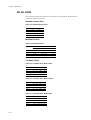
Later, Chapter 5 Barcodes explains the barcode printing capabilities of the command
language.
Chapter 6 Permanent Parameters explains how to reprogram the printing system’s firmware for customization.
Chapter 7 Emulation gives notes on the printing system’s various emulation modes.
An Index is also provided at the end of this manual.
Notice
Most PRESCRIBE commands operate in the same way on all of these models. However,
on particular models, some commands are irrelevant. Model-dependent differences are
noted at the pertinent locations in this manual.
Conventions
•
•
iv
italic is used for emphasis and also refers to a related chapter or section in this manual or another related document.
fixed-pitch means text or commands that you must type exactly as it appears.
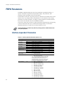
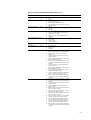
Table of Contents
General Infomation ................................................................................................................................... i
Introduction.............................................................................................................................................iii
Introduction to PRESCRIBE
Format of PRESCRIBE Commands ....................................................................................................1-4
Basic Concepts......................................................................................................................................1-4
Edge Limits ..................................................................................................................................1-4
Margins ........................................................................................................................................1-4
Page Orientation and Direction ....................................................................................................1-5
Coordinate Systems .....................................................................................................................1-7
Text Positioning ...........................................................................................................................1-7
Character Spacing ........................................................................................................................1-8
Paths .............................................................................................................................................1-9
Logical Page and Physical Page ..................................................................................................1-9
Command Parameters .........................................................................................................................1-10
Numeric Parameters ...................................................................................................................1-10
Character Strings ........................................................................................................................1-11
Upper and Lowercase Letters .....................................................................................................1-12
Special Parameters .....................................................................................................................1-13
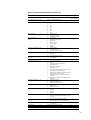
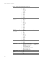
Graphics Tutorial
Drawing Lines ..............................................................................................................................2-2
Drawing Boxes and Circles ..........................................................................................................2-6
Drawing Filled Shapes..................................................................................................................2-9
Path Mode Graphics............................................................................................................................2-16
Path ............................................................................................................................................2-16
Drawing Lines.............................................................................................................................2-18
Miter Limit .................................................................................................................................2-21
Drawing Arcs and Curves ..........................................................................................................2-24
Drawing Complex Curves ..........................................................................................................2-26
Closed Paths ...............................................................................................................................2-29
Filled Areas ................................................................................................................................2-30
Clipping Rectangle .....................................................................................................................2-32
Printing with Character Paths ....................................................................................................2-33
Raster Graphics ..................................................................................................................................2-34
Raster Data Compression Formats .............................................................................................2-34
Commands for Printing Raster Data ..........................................................................................2-35
Printing Raster Data....................................................................................................................2-37
Changing the Printing System’s Imaging Model .......................................................................2-37
Saving and Restoring the Graphics State ...................................................................................2-39
Macros
Examples of Macros .............................................................................................................................3-3
Fonts
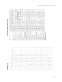
List of Fonts ..................................................................................................................................4-2
KPDL Fonts ..................................................................................................................................4-4
Substituting a Bitmap Font ..........................................................................................................4-6
v
Font Selection ....................................................................................................................................... 4-7
Font Selection by PRESCRIBE Commands ............................................................................... 4-7
Placement of Font Commands ................................................................................................... 4-11
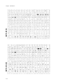
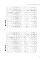
Creation of New Symbols and Characters ......................................................................................... 4-12
Symbol Set.......................................................................................................................................... 4-13
International Characters.............................................................................................................. 4-14
Selecting HP Symbol Sets .......................................................................................................... 4-14
Barcodes
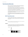
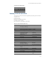
PDF417 Symbol Description...................................................................................................... 5-10
Printing a Two-dimensional Barcode ......................................................................................... 5-12
Limitations of Two-dimensional Barcode.................................................................................. 5-13
Macro PDF417 ........................................................................................................................... 5-14
Creating a Macro PDF 417 Representation................................................................................ 5-14
Permanent Parameters
Interface-dependent Parameters ................................................................................................... 6-2
Interface-independent Parameters ................................................................................................ 6-5
Emulation
Automatic emulation sensing ....................................................................................................... 7-3
General Information on Emulation .............................................................................................. 7-3
Line Printer Emulation (Mode 0) ........................................................................................................ 7-3
IBM Proprinter X24E Emulation (Mode 1) ........................................................................................ 7-4
IBM Proprinter X24E Control Codes........................................................................................... 7-6
Diablo 630 Emulation (Mode 2) ........................................................................................................ 7-12
Diablo 630 Control Codes ......................................................................................................... 7-14
Epson LQ-850 Emulation (Mode 5) .................................................................................................. 7-21
HP LaserJet Emulation (Mode 6) ...................................................................................................... 7-33
LaserJet Fonts ............................................................................................................................. 7-35
LaserJet Symbol Sets.................................................................................................................. 7-37
Resource Protection.................................................................................................................... 7-40
Switching the Print Resolution ................................................................................................... 7-42
HP LaserJet Reset State.............................................................................................................. 7-43
LaserJet PJL................................................................................................................................ 7-43
PJL Syntax Comparison ............................................................................................................. 7-66
HP 7550A Emulation [KC-GL] (Mode 8) ......................................................................................... 7-96
Basic ........................................................................................................................................... 7-96
KC-GL Environment Options .................................................................................................... 7-97
Plotter Status Information ........................................................................................................ 7-102
Device-Control Instructions .................................................................................................... 7-106
Fonts and Symbol Sets in KC-GL ............................................................................................ 7-107
Summary of KC-GL Instructions ............................................................................................ 7-111
KPDL Operators ............................................................................................................................... 7-115
Communication with the Printing System................................................................................ 7-115
KPDL Summary ....................................................................................................................... 7-116
KPDL Error Messages.............................................................................................................. 7-139
KPDL Printable Area................................................................................................................ 7-140
Index
vi
Chapter 1
Introduction to PRESCRIBE
PRESCRIBE is the native language of the Kyocera printing systems including copiers
(collectively referred to as printing systems hereafter). Consisting of easily remembered
commands, such as ‘SLM’ for Set Left Margin, and ‘BOX’ to draw a box, it gives you
the capability to control line and character spacing, adjust margins, change fonts, position text, draw graphics, and print multiple copies of each page. PRESCRIBE also gives
freedom to control device settings including selection of paper source, output stack, and
finishing operations such as sorting, stapling, etc.
Most application software controls printing systems by means of codes and escape
sequences that are built into the program and are not directly visible to the user. In contrast, PRESCRIBE commands are made of ordinary characters that you can type in yourself and see on the computer screen. This makes it easy for you to customize printing and
add features that may not be supported by your application.
This chapter presents an introduction to PRESCRIBE starting with an explanation of the
commands by which you start and exit PRESCRIBE. It is followed by an introduction to
some basic concepts of PRESCRIBE, then a discussion of the command format and
command parameters.
Chapter 1 Introduction to PRESCRIBE
Entry and Exit
The printing system can be thought of as having a multiple personality. When its power
is switched on, it performs the normal printing system functions of printing out files and
other data. Application software can control the printing system using one of the seven
emulations. When the printing system uses an emulation, it is said to be printing in emulation mode.
PRESCRIBE is an additional mode of operation in which the printing system understands data it receives not as text to be printed, but as commands to be executed. The
PRESCRIBE mode is available at any time during operation from any emulation mode.
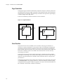
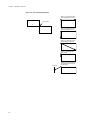
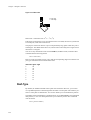
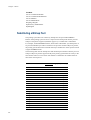
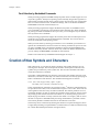
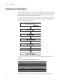
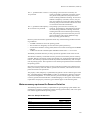
The initializing string that takes the printing system from the usual text-printing mode
into the PRESCRIBE mode is !R!. The command that returns it from the PRESCRIBE
mode to the emulation mode is EXIT;. These transitions are diagramed in the figure
below.
Figure 1. 1. Mode Transitions
The printing system’s emulation mode can be permanently set by the FRPO (Firmware
RePrOgram) P1 command. See Chapter 7 for details. The printing system is factory-set
to emulate the Hewlett-Packard LaserJet.
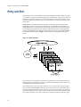
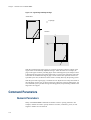
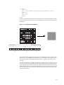
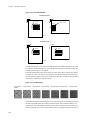
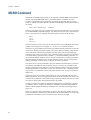
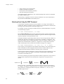
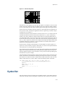
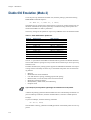
The example below shows how these transitions can be used in a file. The lines beginning with !R! are PRESCRIBE commands. Note how each block of commands begins
with !R! and ends with EXIT;. These sections are not printed; instead, they set margins,
select three different fonts, and draw a box around one line of text. The remainder of the
file consists of ordinary text, and is printed out as shown in the figure on the next page.
1-2
Figure 1. 2. Text Including PRESCRIBE Commands
!R! RES; SLM 1; STM 1; SPD 0.03; FTMD 13;
SFNT "Helvetica-Bd"; EXIT;
WELCOME TO WINDFALL NATIONAL PARK
!R! SFNT "Times-Rom"; EXIT;
The park entrance is located in the rolling hills of
the Northern Woods, a forested area abundant in deer,
elk, squirrel, rabbit, opossum, lynx, wolf, and other
wildlife. It is the park’s most popular area, featuring
excellent trails and campsites for hiking and backpacking.
!R! BOX 3.4, 0.55; FSET 1s5B; EXIT;
Hikers should avoid this area during hunting season.
!R! SFNT "Times-Rom"; EXIT;
Hikers in search of high-altitude adventure will find
Mt.Baker a rewarding...
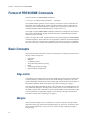
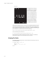
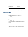
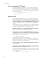
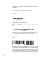
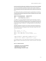
Figure 1. 3. PRESCRIBE Example
The previous example contains five sequences of PRESCRIBE commands. The basic
configuration of a PRESCRIBE command sequence is:
!R! command; command; ...; command; EXIT;
There is a limit to the number of commands you can include between the initial !R! and
the final EXIT;. The initial !R! must be followed by a space, and each command must
end with a semicolon.
Note
The use of PRESCRIBE commands in document files is conditional on the behavior of your
word processing software. Some word processing programs add control codes that interfere with PRESCRIBE. If you cannot control software in this way, try using a non-word processing mode (ASCII text function, for example) of the software.
1-3
Chapter 1 Introduction to PRESCRIBE
Format of PRESCRIBE Commands
The basic format of a PRESCRIBE command is:
• • • or • • • • (command name) parameter, ..., parameter;
The command names generally consist of three or four letters. In most commands, the
parameters must be followed by commas. The last parameter is always followed by a
semicolon. Some commands (RES, for example) have no parameters. In this case, the
command should be followed immediately by a semicolon (RES;).
The length of a single PRESCRIBE command is limited to 255 characters, from the first
letter of the command name through the final semicolon. Commands longer than 255
characters are not executed.
Spaces, carriage return codes, and line feed codes are generally ignored in PRESCRIBE
command sequences. These characters are not generally counted in the command length.
(Exception: Spaces are not ignored in quoted character strings.) To improve readability,
place at least one space before each command or place each command on a separate line.
Basic Concepts
This section discusses a few basic concepts concerning how the printing system prints on
the page. These concepts are:
•
•
•
•
•
•
•
Edge limits
Margins
Coordinate systems
Text positioning/Character spacing
Paths
Logical page and physical page
Page orientation and direction
Edge Limits
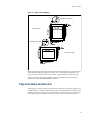
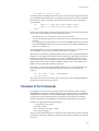
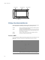
The printing system cannot place print on the outside edges of the paper. The edge limits
to which printing is possible are located 5 mm inside the edges of the paper; or 6 mm
(5mm in landscape orientation) from the left edge and 4 mm from the top of the paper in
HP LaserJet emulation. Refer to the figure Edge Limits and Margins on page 5.
The edge limits adjust automatically to the size of the paper cassette (although not to the
size of manually fed paper). The edge limits can also be set to various standard sizes by
the SPSZ (set paper size) command, or by the equivalent HP LaserJet commands. In HP
LaserJet emulation, the edge limits slightly vary according to the page orientation (as
also shown in Edge Limits and Margins on page 5).
Margins
The top and left margins are set in centimeters or inches in relation to the top and left
edge limits of the page. The bottom and right margins can also be set as a distance from
the top and left edge limits, or they can be set in terms of page width, page length, or
lines per page.
1-4
Basic Concepts
Figure 1. 4. Edge Limits and Margins
Edge limits in HP emulation
Portrait Orientation
Edge limits in HP emulation
Landscape orientation
When the printing system passes the bottom margin while printing text, it prints the page
and feeds to the next page. Spacing is carried over, so if the bottom margin does not
occur at an exact number of lines, excess space is printed at the top of the next page.
If you are using word-processing software that sets the margins automatically, you
should not set them with PRESCRIBE commands.
Page Orientation and Direction
The term page orientation refers to the direction in which text is placed on the page. In a
vertical direction, it would be called portrait and a horizontal direction would be called
landscape. The term print direction, which follows this section, refers to the orientation
of the logical page’s coordinate system with respect to the current page orientation.
1-5
Chapter 1 Introduction to PRESCRIBE
Page Orientation
Changing the page orientation automatically adjusts the margins so that they remain the
same distance from the four edges of the paper. If the printing system cannot make these
margin settings (for example, if the left margin would be to the right of the right margin),
it sets the margins to the edge limits.
Fonts are automatically rotated to match the current orientation.
Figure 1. 5. Page Orientations
Portrait Orientation
Top
margin
Right
margin
Left
margin
Bottom
margin
Right
margin
Left
margin
Bottom
margin
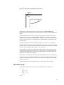
Print Direction
The print direction can be modified in 90° increments. These page orientations are
referred to as portrait, landscape, reverse portrait, and reverse landscape. Changing the
print direction rotates the page coordinate system in the same manner as changing the
page orientation. However, in this case, portrait refers to the print direction in which the
axes of the coordinate system are oriented in the same direction as for the currently
selected page orientation.
Changing the print direction also changes the margins to maintain the same printable
area as prior to the change. The current position (the physical location in which the next
character will be printed) and its coordinate values remain the same as in the previous
print direction.
Changing the print direction also changes the orientation of any subsequent raster graphics and PRESCRIBE vector graphics. However, it does not affect the orientation of any
subsequent HP-GL/2 graphics. (HP-GL/2 graphics can only be rotated with the HP-GL/2
RO command or the LaserJet orientation command.)
1-6
Basic Concepts
Figure 1. 6. Print Direction
Portrait print direction
Landscape print direction
Current Point
Left
margin
Top
margin
Current Point
Bottom margin
Bottom margin
Top
margin
Right margin
Left margin
Right margin
Reverse landscape print direction
Reverse portrait print direction
Current point
Top margin
Left margin
Bottom margin
Left
margin
Bottom margin
Top margin
Current point
Right margin
Right margin
Coordinate Systems
With PRESCRIBE, positions on a page are described in terms of X and Y coordinates.
The origin of the coordinate system (the position at which X and Y both equal 0) is
located at the intersection of the top margin and the left margin. Values of X greater than
0 indicate positions to the right of the origin, and values of Y indicate positions below the
origin. See the figure on page 10. When the top and left margins are changed, the physical position of the origin changes accordingly.
Text Positioning
The printing system always keeps track of its current position on the page. The current
position can be thought of as a cursor that moves as data is printed. At any instant, the
1-7
Chapter 1 Introduction to PRESCRIBE
cursor indicates where the next character will be printed or the next graphics will be
drawn. (The printing system does not have separate cursors for text and graphics.)
Text and graphics can be positioned at arbitrary locations on the page by moving the cursor with positioning commands (MAP, for example).
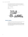
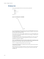
Figure 1. 7. Text Positioning
TITLE
!R! BOX 1, 1; MRP 2, 1;
EXIT; LABEL
Landscape Orientation
Carriage Return
MRP 2, 1;
BOX 1, 1;
Space after EXIT;
Cursor ends here
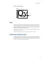
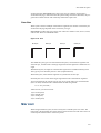
Character Spacing
Each character is printed within an individual cell as shown below. The character sits on
a line called the baseline. Characters such as y descend below the base line.
In some character fonts, all the character cells are the same size, so the number of character positions per inch is fixed. In other fonts, the size of character cells is proportional to
the size of characters. These proportional fonts produce text that is easier to read. However, in order to align the right margin, you must use software that supports the printing
system’s proportional spacing.
1-8
Basic Concepts
Figure 1. 8. Character Spacing
Font height
Baseline
Paths
A path is a set of straight and curved line segments. Paths can be open, as in the case of
lines, or closed, as in the case of rectangles, circles, or any fully enclosed area of any
shape. The segments may be connected with one another, or they may be disconnected.
Further, a path may contain multiple closed subpaths, representing several areas, and
they may intersect themselves in arbitrary ways.
Paths can be used to draw lines and curves or specify boundaries of filled areas, including the outline of a character.
Paths are explained more fully in section Path Mode Graphics on page 16.
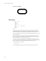
Logical Page and Physical Page
The logical page defines the limits of the coordinates within which text and graphics can
be located. There are two types of logical page, as shown in the following figure. The
standard mode logical page imposes limits on specifiable coordinates. The coordinates
have no limitations for the path mode logical page.
1-9
Chapter 1 Introduction to PRESCRIBE
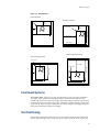
Figure 1. 9. Logical Page and Physical Page
Standard Mode
(0,0)
x
= Logical page
y
Path Mode
−y
−x
x
y
With the standard mode logical page, any position specification that lies outside of the
logical limits is automatically adjusted to bring it within the limits. For example, the
page on the upper left in the preceding figure shows what happens if you attempt to draw
a diagonal line from below the bottom edge limit to a point to the right of the right edge
limit when the standard mode logical page is used. The fine line represents the line as
specified by the user; the thick line shows what is actually drawn by the printing system.
With the path mode logical page, coordinates are not adjusted even if they fall outside of
the edge limits. In this case, as shown in the lower right page in the preceding figure, the
line is defined by the specified starting and ending points, but parts falling outside of the
edge limits are clipped.
Command Parameters
Numeric Parameters
Many of the PRESCRIBE commands use number values to specify parameters. For
example, numbers are used to specify distances in inches, centimeters, points, or dots.
Negative numbers are also allowed.
1-10
Command Parameters
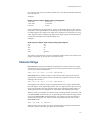
For computer code values beyond four decimal places, the fifth and subsequent decimal
places are ignored.
Examples:
Number output by computer
1234.1234
-1234.1234
0.123456
Number used by printing system
1234.1234
-1234.1234
0.1234
Some commands have angle parameters. Angles are specified in degrees. (The printing
system does not recognize radians). The printing system rounds off all angles to the nearest integral degree. Only angles in the range from -360 degrees to 360 degrees are recognized. Angles less than -360 degrees are ignored, and angles greater than 360 degrees are
treated as the remainder of the angle divided by 360.
Examples:
Angle output by computer
90
-90
90.4
90.5
-400
Angle used by printing system (degrees)
90
-90
90
91
Ignored
The printing system does not accept the exponential notation used in some computer languages. For example, do not specify 1E-3 instead of 0.001.
Character Strings
PRESCRIBE text-printing commands have parameters that consist of character strings.
A character string is any string of characters enclosed by quotation marks or apostrophes,
such as shown in the example below.
TEXT ’You are about to enter PRESCRIBE.’;
PRESCRIBE allows character strings to be enclosed in either single quotation marks
(apostrophes) or double quotation marks. The following example has exactly the same
meaning as the one above.
TEXT "You are about to enter PRESCRIBE.";
The beginning of a character string is recognized when the first single or double quotation mark appears. If the beginning quotation mark is a single quotation mark, the string
does not end until the next single quotation mark. If the beginning quotation mark is a
double quotation mark, the string does not end until the next double quotation mark.
Whatever comes in the middle of a character string, including commas, semicolons, and
even PRESCRIBE command names, is recognized as part of the character string, and not
as part of the PRESCRIBE command language. For example, the expression EXIT; in
the following string is just text; it does not cause the printing system to exit from the
PRESCRIBE mode.
TEXT ’NO EXIT; NO RETURN.’;
When the string itself contains one type of quotation mark, the quotation mark must be
enclosed in quotes of the other type. Here are two examples:
1-11
Chapter 1 Introduction to PRESCRIBE
TEXT "You’re about to enter PRESCRIBE.";
TEXT ’ " " " ’;
In the first command above, the character string starts with a double quotation mark. The
printing system therefore expects the string to end with a double quotation mark, and
regards the apostrophe in the word You’re as an ordinary character, not as the string terminator.
Similarly, the double quotation marks in the second command above are recognized as
ordinary characters, not as string terminators.
Since an apostrophe or quotation mark can start a character string anywhere in a PRESCRIBE command sequence, it is important not to start character strings unintentionally.
The following examples demonstrate incorrect use of apostrophes and double quotation
marks.
Incorrect:
!R! CMNT Don’t leave stray apostrophes; EXIT;
Incorrect:
!R! CMNT The symbol " means inches; EXIT;
In both of the above cases, the printing system assumes that the expression EXIT; is part
of a character string started by the preceding apostrophe or quotation mark, and fails to
exit the PRESCRIBE mode. The correct way to write these comments is:
Correct:
!R! CMNT "Don’t leave stray apostrophes"; EXIT;
Correct:
!R! CMNT ’The symbol " means inches’; EXIT;
Character strings must not exceed the 255-character limit on total command length. If a
character string exceeds this limit, the printing system terminates it forcibly and begins
looking for the next PRESCRIBE command.
Upper and Lowercase Letters
Regarding upper and lowercase characters, PRESCRIBE follows the same rule as many
computer programming languages: it discriminates case inside character strings and
ignores it elsewhere. You can type command names in upper or lowercase.
Correct:
!R! TEXT ’A’; CIR 1; EXIT;
Also correct:
!R! text ’A’; cir 1; exit;
Also correct:
1-12
Command Parameters
!R! Text ’A’; Cir 1; Exit;
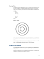
Each of these commands prints the capital letter ‘A’ inside a circle. In the printout shown
above, the unit is centimeters. The reason that the letter ‘A’ is off center in the circle is
that the cursor is not located at the center of the circle, but at left corner of the letter ‘A’.
The command
!R! TEXT ’a’; CIR 1; EXIT;
prints a lowercase a because the letter occurs inside a character string.
The sole exception to upper and lowercase usage in PRESCRIBE commands occurs with
the initializing !R! command. This command must always use an uppercase R. The printing system will not enter the PRESCRIBE mode in response to !r!.
In this manual, PRESCRIBE commands are printed in upper-case for readability.
Outside of PRESCRIBE mode, the printing system always distinguishes between uppercase and lowercase letters and prints exactly what is sent.
Special Parameters
Some PRESCRIBE commands use unquoted strings of characters as parameters. Examples for these are the FSET (change current font set by characteristic) command and the
CSET (change symbol set by symbol-set ID) command. (See Chapter 4 for a detailed
explanation of how these commands are used to select fonts.)
The FSET and CSET commands use parameters that closely resemble the command
parameters used for font control in Hewlett-Packard’s printer control language. For
example, the PRESCRIBE command
FSET 0p12h12v0s0b6T;
selects the font whose characteristics most closely matches the following font parameters:
•
•
•
•
•
•
Monospaced font (0p)
Character spacing of 12 characters/inch (12h)
Character height of 12 points (12v)
Upright style (0s)
Medium weight (0b)
LetterGothicBM12-Roman typeface (6T)
In Hewlett-Packard’s PCL, the corresponding command would be
ESC(s0p12h12v0s0b6T
1-13
Chapter 1 Introduction to PRESCRIBE
Similarly, the PRESCRIBE command CSET 11U; designates use of the PC-8 Danish/Norwegian symbol set. The corresponding Hewlett-Packard PCL command is
ESC(11U.
1-14
Chapter 2
Graphics Tutorial
PRESCRIBE provides a wide variety of graphics operators, allowing you to easily construct and print almost any imaginable shape or pattern.
This chapter introduces the various graphics concepts of PRESCRIBE, and illustrates
how to use many of its graphic functions. It defines standard graphics mode, path mode
graphics, and raster graphics. It explains how to use predefined fill patterns, how to
define your own fill patterns, and introduces ways in which you can change the print
model, the rules that determine the manner in which patterns and images are rendered on
the paper.
Chapter 2 Graphics Tutorial
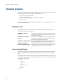
Standard Graphics
The standard graphics mode provides a number of operators for constructing a variety of
filled shapes and lines. Using standard mode graphics, you can:
•
•
•
•
Draw lines of any desired width
Draw circles and rectangles
Draw a variety of filled shapes, including boxes and arcs
Draw pie charts
This is referred to as the standard graphics mode because it is a standard feature of all
versions of PRESCRIBE.
Drawing Lines
PRESCRIBE provides a number of Draw to commands for drawing lines in both standard and path modes. These include:
DAP (draw to absolute
position)
Draws a line to an absolute position in a Cartesian coordinate system whose origin (0,0) is at the intersection of
the left and top margins.
DZP (draw to zero-relative
Draws a line to an absolute position in a Cartesian coorposition)
dinate system whose origin (0,0) is at the intersection of
the left and top edge limits of the paper.
DRP (draw to relative position) Draws a line to a position specified as a horizontal and vertical displacement from the current cursor position.
DRPA (draw to relative
Draws a line to a position that is specified as a distance and
position specified by angle)
angle from the current cursor position. Examples of these
commands are given in the sections that follow.
Lines to Absolute Position
Begin with a simple task such as drawing a line between two arbitrary points on a page.
Use the MAP and DAP commands to specify positions relative to the top and left margins.
This task has several distinct steps: selecting a line width, determining the starting point
of the line, and determining the end point of the line. The following command sequence
demonstrates this process.
!R! RES;
STM 0.5;
SLM 0.5;
SPD 0.01;
MAP 0.5, 1;
DAP 2, 0.5;
PAGE;
EXIT;
2-2
Figure 2. 1. Result of Draw Commands: Absolute Lines
Edge limits
Margins
DAP 2, 0.5;
MAP 0.5, 1;
The initial !R! command switches the printing system to the PRESCRIBE mode.
Remember that this command must always precede each sequence of PRESCRIBE commands.
The RES (RESet) clears the current page from printing system memory and re-establishes the printing system’s permanent defaults. Although you would not include this
command in every sequence of PRESCRIBE commands, we include it in this example to
ensure consistent results. As a standard practice, include the RES at the beginning and
end of each job.
The STM and SLM set both the top and left margins to 0.5 inches (1.27 centimeters).
The SPD (Set Pen Diameter) command determines the thickness of lines. In the standard
graphics mode, this setting determines the thickness of all lines drawn after the command
is issued. In this example, the line width is set to 0.01 inches.
The starting point of the line is established with the MAP (Move to Absolute Position)
command. This command moves the cursor to a point that is a specified distance from
the top and left margins. In this example, the point specified is 0.5 inches from the left
margin and 1 inch from the top margin.
If the margins are changed, the position specified by MAP also changes correspondingly.
On the next line of the program, the DAP (Draw to Absolute Position) command draws a
line from the starting position to the point 2 inches from the left margin and 0.5 inches
from the top margin.
Finally, PAGE; prints out the page, allowing us to look at the result of our work.
Zero-relative Lines
The line draw example below uses some new commands to draw another line.
!R! RES;
SPD 0.01;
MZP 0.5, 1;
DZP 2, 0.5;
PAGE;
EXIT;
2-3
Chapter 2 Graphics Tutorial
Figure 2. 2. Result of Draw Commands: Zero-relative Lines
Edge limits
DZP 2, 0.5;
MZP 0.5, 1;
The first two lines switch the printing system to the PRESCRIBE mode, reset printing
system parameters, and set the line width to 0.01 inch. On the third line, the MZP (Move
to Zero-relative Position) differs from the MAP (Move to Absolute Position) command
in one respect: the position specified is in relation to the top and left edge page limits of
the page, rather than in relation to the top and left page margins. MZP moves the cursor
to the point that is 0.5 inches from the left edge limit and 1 inch from the top edge limit.
Similarly, on the next line, DZP (Draw to Zero-relative Position) draws a line from the
starting position to the point 2 inches from the left edge limit and 0.5 inches from the top
edge limit.
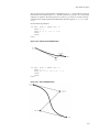
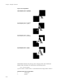
Relative Lines
Another way to specify positions is in relation to the current cursor position. The following command sequence provides an example.
!R! RES;
SPD 0.01;
MRP 2, 1;
DRP -1.5, -1;
MRP 2, 1;
DRP -1.5, -1;
MRP 2, 1;
DRP -1.5, -1;
PAGE;
EXIT;
2-4
Figure 2. 3. Result of Draw Commands: Relative Lines
Edge limits
In this command sequence, the PRESCRIBE mode begins with the !R!, resets the printing system defaults to permanent settings with RES;, and establishes a pen width of 0.01
inches with the SPD 0.01;.
The MRP (Move to Relative Position) and DRP (Draw to Relative Position) specify
positions in relation to the cursor’s current position.
When the command sequence starts, the cursor is located at the intersection of the left
and top margins. The command MRP 2, 1; on line 3 moves the cursor 2 inches to the
right of its current position, and down 1 inch from its current position. Then the command DRP -1.5, -1; draws a line from that point to a point 1.5 inches to the left of the
cursor position and 1 inch above it. The cursor winds up 0.5 inches to the right of the
point where it started.
Lines 5 to 8 repeat the move-and-draw sequence two more times. This produces three
parallel lines, as shown in the figure on the previous page.
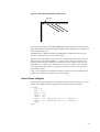
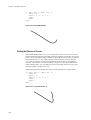
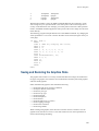
Lines in Terms of Angles
Until now, all of our examples have specified positions in terms of Cartesian (X,Y) coordinates. This example illustrates drawing lines of specified lengths and angles.
!R! RES;
SPD 0.01;
MZP 5, 4;
DRPA 2, 149;
DRPA 2, 221;
DRPA 2, 293;
DRPA 2, 365; CMNT Equivalent to 5 degrees;
DRPA 2, 437; CMNT Equivalent to 77 degrees;
PAGE;
EXIT;
2-5
Chapter 2 Graphics Tutorial
Figure 2. 4. Result of Draw Commands: Lines in Angles
The first two lines of this command sequence initiates the PRESCRIBE mode, resets
printing system defaults to permanent settings, and sets the line width to 0.01 inches.
Then the MZP command on line 3 moves the cursor to a point 5 inches to the right of the
left edge limit and 4 inches below the top edge limit.
Next, DRPA 2, 149; on line 4 draws a line two inches long at an angle of 149 degrees.
The angle is measured clockwise from the vertical axis. The subsequent DRPA commands draw additional 2-inch lines at angles that increase in increments of 72 degrees.
As indicated by the CMNT (CoMmeNT) commands, angles that exceed 360 degrees are
equivalent to the remainder of division of the angle by 360.
Drawing Boxes and Circles
PRESCRIBE provides two commands especially for drawing boxes (BOX command)
and circles (CIR command).
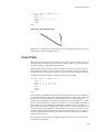
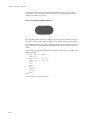
Drawing Boxes
The BOX (draw box) command draws a box of a specified width and height. As with the
line drawing commands, the thickness of the line used to draw the box is determined by
the SPD (set pen diameter) command.
The following command sequence draws a box.
!R! RES;
UNIT C;
SPD 0.1;
MZP 3, 3;
BOX 3, 4;
PAGE;
EXIT;
2-6
Figure 2. 5. An Example of a Box
Line 1 places the printing system in the PRESCRIBE mode and resets printing system
parameters. The UNIT C; command on the second line sets the unit of measurement to
centimeters, and the SPD (Set Pen Diameter) command on line 3 sets the line width to
0.1 centimeters. (If you omit these two commands, the printing system will print using
the default unit, inches; and the default line width, 3 dots.)
Next, the MZP command on line four moves the cursor to the point that is 3 centimeters
to the right of the left edge limit and 3 centimeters below the top edge limit. This is the
starting point from which the box is drawn.
On line 5, BOX 3, 4; draws a box with a width of 3 centimeters and a height of 4 centimeters.
The position of the box with respect to the cursor depends on the positive or negative
value specified for width and height. The box is drawn to the right of the cursor if width
is positive, and to the left of the cursor if width is negative. Similarly, the box is drawn
below the cursor if height is positive, and above the cursor if height is negative. This
relation is illustrated in the figure that follows.
By default, the position of the cursor is not affected by this command. However, you can
also specify an option parameter to make the cursor move to an adjacent or diagonally
opposite corner of the box, down by one text line, or to the left margin on the next text
line. The following figure shows some examples.
2-7
Chapter 2 Graphics Tutorial
Figure 2. 6. Cursor Positioning Options
BOX 4, 2, H; Moves the cursor to
the horizontally adjacent corner
Cursor position
-Y
-X
X
BOX 4, 2, V; Moves the cursor to
the vertically adjacent corner
Y
BOX 4, 2, E; Moves the cursor to
the diagonally opposite corner
BOX 4, 2, L; Moves the cursor
down one line
Left margin
2-8
BOX 4, 2, N; Moves the cursor to
the beginning of the next line (to
the left margin)
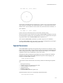
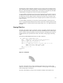
Drawing Circles
The CIR (draw circle) command draws a circle of a specified radius using the line thickness set by the SPD (set pen diameter) command. The circle drawn is centered on the
current cursor position; the position of the cursor remains unaffected. See the following
example:
!R! RES;
UNIT C;
SPD 0.1;
MZP 8, 8;
CIR 1;
CIR 2;
CIR 3;
PAGE;
EXIT;
Figure 2. 7. Circles
Lines 1, 2 and 3 start PRESCRIBE mode, reset the printing system to its default parameters, establish the unit of measurement as centimeters, and set the line width to 0.1 centimeters.
Next, the MZP command moves the cursor to the point that is 8 centimeters to the right
of the left edge limit and 8 centimeters below the top edge limit.
Lines 5, 6, and 7 draw three circles with radii of 1, 2, and 3 centimeters.
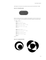
Drawing Filled Shapes
The standard graphics mode provides two types of filled shapes: arcs and blocks. Such
shapes are filled with one of the printing system’s predefined patterns, or with a user
defined pattern.
Filled areas of other shapes can be printed using path mode graphics. For details, see the
explanation in section Path Mode Graphics on page 16.
2-9
Chapter 2 Graphics Tutorial
A filled block consists simply of a rectangle of any desired dimensions. A filled arc is an
area enclosed by an arc segment and the line segments extending from the ends of the arc
to the center of the circle of which the arc is a part.
This section shows how to select a fill pattern and print a filled block or arc.
Drawing Filled Blocks
The following command sequence prints the block shown below.
!R! RES;
UNIT P;
MZP 72, 72;
PAT 6;
BLK 72, -144, H;
PAGE;
EXIT;
Figure 2. 8. A Filled Block
Lines 1 and 2 put the printing system in the PRESCRIBE mode, reset printing system
parameters and set the unit of measurement to points. (One point is equal to 1/72 inches.)
Next, the MZP command moves the cursor to the position 72 points to the right of the
left edge limit and 72 points below the top edge limit.
The PAT (select fill PATtern) command on line 4 of the program selects the fill pattern.
In this program, pattern number 6 is selected.
You can select from among any of the printing system’s 60 predefined fill patterns or
choose to define a pattern using the XPAT (generate eXpanded PATtern) command. In
either case, the selection is made with the PAT command. For 1200-dpi and 600-dpi
models, the user can define the printing resolution (300, 600, 1200 dpi) of the pattern by
giving a second parameter to the PAT command.
You can also select a shade of gray for filling the arc or block by using the GPAT (set
Gray PATtern) command.
It is possible to apply a color to a pattern specified using PAT, FPAT, GPAT or XPAT.
Note, however, that this may not always result in the exact same pattern as printed in
monochrome.
The way a color looks may differ when used for different patterns even though the same
color has been specified.
2-10
The BLK (draw filled-in BLocK) command on line 5 actually draws the filled in block.
This command closely resembles the BOX command explained in the preceding section.
However, whereas the BOX command draws a line around a rectangular area, the BLK
command fills a rectangular area with the currently selected pattern.
As with the BOX command, the position of the rectangular area with respect to the cursor depends on the sign of the values specified for width and height. The box is drawn to
the right of the cursor if width is positive, and to the left of the cursor if width is negative; and the box is drawn below the cursor if height is positive, and above the cursor if
height is negative.
As with the BOX command, you can specify an option parameter to make the cursor
move to a specified location after the box is drawn. (The cursor remains unmoved if the
option parameter is omitted.) Values for this option are H, V, E, L, N, and B, the same as
for BOX.
Drawing Filled Arcs
The ARC (draw filled-in ARC) command is similar to the BLK command (described in
the preceding section) in that it fills an area with a pre-defined pattern or a shade of gray.
The arc is drawn centered around the current cursor position. The dimensions of the arc
are determined by user specified inner radius, outer radius, starting angle, and ending
angle.
The following PRESCRIBE demonstrates the ARC command.
!R! CMNT Enter PRESCRIBE mode;
RES;
CMNT Reset printing system parameters;
UNIT C; CMNT Set centimeters as unit;
PAT 9; CMNT Select pattern 9;
MZP 8, 8; CMNT Move cursor to point that is 8 cm;
CMNT from left edge limit and;
CMNT 8 cm from top edge limit;
ARC 1, 2, 0, 90;
PAGE;
EXIT;
Figure 2. 9. A Filled Arc
The ARC command on line 8 of the command sequence draws an arc with an inner
radius of 1 centimeter, an outer radius of 2 centimeters, a starting angle of 0 (straight up),
and an ending angle of 90 degrees.
The ARC command does not draw a line around the boundary of the filled-in area.
2-11
Chapter 2 Graphics Tutorial
Defining Fill Patterns
With a little work, you can construct your own fill patterns. You can generate 8 × 8 dot
patterns using the FPAT (generate Fill PATtern) command, or 16 × 16 dot patterns using
the XPAT (generate eXpanded fill PATtern) command. This section gives examples of
both.
!R! RES;
MZP 1, 1;
FPAT 16, 40, 68, 130, 65, 34, 20, 8;
BLK 1, 1;
PAGE;
EXIT;
Line 4 of this command sequence prints a filled block using a fill pattern defined by the
FPAT command on line 3.
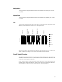
Each of the eight numbers in the FPAT defines one row of an 8 × 8 dot pattern. The pattern follows:
Figure 2. 10. Dot Pattern and a Filled Block
128
64
32
16
8
4
2
1
= 16
= 40
= 68
= 130
= 65
= 34
= 20
= 8
For this pattern, the numbers across the top indicate the value of each column. The numbers down the right side are the sums of the values of columns that contain black dots in
that row.
Once this pattern has been defined by the FPAT command, it is used as the fill pattern
until printing system parameters are reset with RES, another pattern is selected with PAT,
a different pattern is defined with FPAT, or a shade of gray is defined and selected by
GPAT.
Now let’s look at an example using the XPAT command.
The XPAT command uses the format
XPAT pattern-number; bit map;
Note that the pattern-number parameter must be a value from 100 to 105 and followed
by a semicolon, not a comma.
The following example demonstrates the XPAT command in a PRESCRIBE command
sequence.
2-12
!R! RES;
XPAT 100;
@X0@ | 0Af0CC0FA8L@<X@6p@3p@3X@6L@<FA8CC0Af0@ | 0@X0;
MZP 1, 1;
PAT 100;
BLK 1, 1;
PAGE;
EXIT;
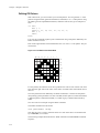
Lines 2 and 3 define the pattern shown in the figure on the next page, defining it as pattern 100. The PAT command on line 5 selects the pattern for use in fills. Line 6 prints the
filled block.
Figure 2. 11. Dot Pattern and a Filled Block
16 bits
32
16
8
4
6 bits (x)
+
64
2
1
32
16
8
4
6 bits (y)
+
64
2
1
8
4
2
1
4 bits (z)
+
48
The pattern is 16 dots high and 16 dots wide, and is encoded as a series of 16-bit words.
Each 16-bit word is encoded by three characters, representing the most significant six
bits, the next six bits, and the least significant four bits, respectively, as shown on the
next page.
You obtain the characters that define the pattern by dividing each row-work into sections
of six, six, and four bits, calculating the numerical value of each section (referred to as x,
y, and z, respectively), treating it as a binary number in which the white dots are zeroes
and the black dots are ones. Then add 64 (decimal) to the values of the 6-bit sections and
48 to the values of the 4-bit sections. The result is the ASCII code of the character that
represents that section.
2-13
Chapter 2 Graphics Tutorial
Column value
0+64=64 (@) 24+64=88 (X) 0+48=48 (0)
0+64=64 (@) 60+64=124 (|) 0+48=48 (0)
1+64=65 (A) 38+64=102 (f) 0+48=48 (0)
3+64=67 (C) 3+64=67 (C) 0+48=48 (0)
6+64=70 (F) 1+64=65 (A) 8+48=56 (8)
12+64=76 (L) 0+64=64 (@) 12+48=60 (<)
24+64=88 (X) 0+64=64 (@) 6+48=54 (6)
48+64=112 (p) 0+64=64 (@) 3+48=51 (3)
48+64=112 (p) 0+64=64 (@) 3+48=51 (3)
24+64=88 (X) 0+64=64 (@) 6+48=54 (6)
12+64=76 (L) 0+64=64 (@) 12+48=60 (<)
6+64=70 (F) 1+64=65 (A) 8+48=56 (8)
3+64=67 (C) 3+64=67 (C) 0+48=48 (0)
1+64=65 (A) 38+64=102 (f) 0+48=48 (0)
0+64=64 (@) 60+64=124 (|) 0+48=48 (0)
0+64=64 (@) 24+64=88 (X) 0+48=48 (0)
If the character resulting for section x of any row is @ (indicating that all bits in that section are white), then that character may be omitted. If sections x and y are both @, then
both characters may be omitted. However, if the result for section y is @ and that for section x is a character other than @, then no characters may be omitted. In terms of the program example above, what this means is that the bit map string,
@X0@ | 0Af0CC0FA8L@<X@6p@3p@3X@6L@<FA8CC0Af0@ | 0@X0;
may be shortened by four characters to:
X0 | 0Af0CC0FA8L@<X@6p@3p@3X@6L@<FA8CC0Af0 | 0X0;
Patterns defined by the XPAT command remain effective until they are redefined by
another XPAT command, or until the printing system is turned off.
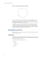
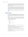
Drawing Pie Charts
The standard graphics mode provides a convenient function for drawing pie charts. See
the following example:
!R! RES; UNIT C; SPD .05;
MZP 10, 10;
PIE 2, 0, 10, 20, 30, 40;
PAGE;
EXIT;
2-14
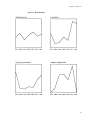
Figure 2. 12. PIE Example
The PIE command uses the format
PIE radius, starting angle, size of slice, ...;
In the example above, the radius is 2 centimeters (since we set the unit to centimeters
with the UNIT command), and the starting angle is 0 degrees. Four pie slices are specified, with sizes of 10, 20, 30, and 40.
The printing system automatically converts the slice sizes to angles totalling 360
degrees. Then it draws the first slice with a cut at the angle specified by the second
parameter (0 degrees in our example, or straight up). The remaining slices are drawn in
sequence clockwise around the circle. The line thickness used for drawing the circle and
the lines between slices are designated by the SPD (Set Pen Diameter) command.
Any number of pie slice sizes can be specified, provided that the total length of the command does not exceed 255 characters, and that the sum of the pie slices does not exceed
9999. All numbers specified for slice sizes must be non-negative integers.
The PIE command does not fill in the slices with any fill pattern. The PAT command can
be used to create shaded areas. The previous example is expanded to fill in the slices.
!R! RES; UNIT C; SPD .1;
MZP 10, 10;
PAT 19; ARC 0, 2, 0, 36;
PAT 41; ARC 0, 2, 36, 108;
PAT 43; ARC 0, 2, 108, 216;
PAT 48; ARC 0, 2, 216, 360;
PIE 2, 0, 10, 20, 30, 40;
PAGE;
EXIT;
2-15
Chapter 2 Graphics Tutorial
Figure 2. 13. Pattern Filled PIE
This program first draws four filled arcs, each using a different fill pattern, then prints
the pie chart over the arcs. Each arc has an inner radius of zero, an outer radius of 2 (the
same as the pie chart), and a starting angle and ending angle that correspond to the relative size of the pie slices. Since the total size of the pie slices in the example is 100
(10+20+30+40), the angular extent of each arc is equal to 360 x size of slice /100. For
example, the angular extent of the first arc is 360 x 10 /100 = 36 degrees. The starting
angle of each arc equals the starting angle of the pie chart (0 degrees), plus the angular
extent of all the preceding arcs. The ending angle equals the starting angle plus the angular extent of the arc.
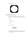
Path Mode Graphics
With path mode graphics, images are constructed by defining lines and curves as paths,
then rendering them as images by stroking along the paths or filling the area enclosed by
them. PRESCRIBE provides a variety of path construction operators and painting operators for stroking or filling paths.
Path
In PRESCRIBE, a path is a set of straight or curved line segments, either connected or
disconnected, that describes the shape and position of one or more objects or regions.
Paths can be used to draw lines and curves and to specify boundaries of filled areas.
A path is stroked by drawing a line of arbitrary width along it. The line may be solid
black, all white, or any intermediate shade of gray. It may also be a dashed line of any
pattern of segment lengths.
A path is filled by painting the entire area that it encloses with a gray scale pattern, ranging from black to white, or with one of the printing system’s predefined patterns. In order
to be filled, a path must be closed; that is, it must return to its starting point.
A path is constructed by means of one or more path construction operators. The path
construction operators modify the current path, usually by appending to it. However, a
path in itself does not produce any image on the page. Once a path has been constructed,
it can be used to control the application of one of the painting operators of PRESCRIBE,
defining the boundary of the area in which images can be printed.
2-16
Path Mode Graphics
There are no restrictions on the shape of a path. A single path may include multiple
closed subpaths, representing several areas, and a path may intersect itself in an arbitrary
manner.
The order of the segments that define a path is significant. A pair of line segments is said
to connect only if they are defined consecutively, with the second segment starting where
the first one ends. Non-consecutive segments that meet or intersect fortuitously are not
connected.
A subpath is a sequence of connected segments. A path is made up of one or more subpaths. Subpaths may be either open or closed.
Path construction begins with a NEWP (NEW Path) command. Path construction ends
with the CLSP (CLoSe Path) command or with any paint operator that paints the region
enclosed by the path or draws a line along it (such as STRoKe or FILL).
2-17
Chapter 2 Graphics Tutorial
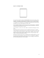
Drawing Lines
The following example shows how to draw a line in the path mode.
!R! RES;
NEWP;
PMZP 1, 1;
PDZP 2, 3;
STRK;
PAGE;
EXIT;
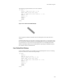
Figure 2. 14. Drawing Lines in Path Mode
(1, 1)
(2, 3)
Line 1 of the program switches the printing system to the PRESCRIBE mode and resets
printing system parameters, including the unit (to inches), line width (to 3 dots), and various other aspects of the graphics state.
Path construction begins with the NEWP command on line 2. This command empties the
current path (if any), making it possible to start a new one. In doing so, it makes the position of the cursor undefined.
The PMZP (Path, Move to Zero-relative Position) command on line 3 moves the cursor
to a position one inch from the top and left edge limits of the paper. The coordinates
specified may be positive or negative.
On line 4, the PDZP (Path, Draw to Zero-relative Position) draws a line from the current
cursor position to the position 2 inches from the left edge limit and 3 inches from the top
edge limit. The cursor remains at this position after the line is drawn.
On line 5, the STRK command strokes the path onto the page.
After stroking the current path, the STRK command clears the path in the same manner
as NEWP (start NEW Path).
Finally, PAGE prints out the page, allowing us to look at the result of our work and cancelling all changes made during the course of the program, then EXIT ends the PRESCRIBE mode.
2-18
Path Mode Graphics
Two Lines
The preceding example illustrated construction of a path between points specified in
terms of absolute coordinates. The following program draws two lines, using both absolute coordinate specification and a new method: relative coordinate specification.
!R! RES;
NEWP;
PMZP 1, 1;
PDZP 2, 3;
PMRP .5, -1;
PDRP -1, -1;
SPD 0.04;
STRK;
PAGE;
EXIT;
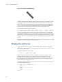
Figure 2. 15. Drawing Two Lines
(1, 1)
(-1, -1)
(0.5, -1)
(2, 3)
The first four lines of this program are identical to the preceding example. Line 1
switches the printing system to the PRESCRIBE mode and resets printing system parameters, line 2 empties the current path, and lines 3 and 4 draw a line between two points
that are specified in terms of absolute coordinates.
On line 5, the PMRP (Path, Move to Relative Position) command moves the cursor to the
point half an inch to the right and one inch above the current cursor position; that is, the
point at which the first line ends. Then the PDRP (Path, Draw to Relative Position) command on line 6 draws a line to the point 1 inch to the left of the new position and 1 inch
below it.
The line thickness is changed to 0.04 inches by the SPD command on line 7.
Finally, the STRK command on line 8 strokes the path onto the page, PAGE prints out
the page, and EXIT ends the PRESCRIBE mode.
2-19
Chapter 2 Graphics Tutorial
Line Ends
The line end type determines how PRESCRIBE renders the ends of lines when they are
stroked onto the page. PRESCRIBE provides three kinds of line ends. These include:
Figure 2. 16. Line Ends
Square caps
Butt caps
Round caps
The default line end type is butt caps. You can switch from the current line end type to
any of the other types with the SCAP command. This command uses the following format:
SCAP line-cap mode;
Values for line-cap mode include:
1 (for square caps)
2 (for butt caps)
3 (for round caps)
Use of this command is illustrated in the following example.
!R! RES;
UNIT C; CMNT Sets unit to cm;
NEWP; CMNT Starts new path;
SPD .5; CMNT Sets line width to .5 cm;
SCAP 1; CMNT Sets square caps;
PMZP 2, 2;
PDZP 4, 4;
SCAP 3; CMNT Sets round caps;
STRK;
PAGE;
EXIT;
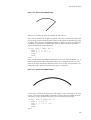
Figure 2. 17. Printout of SCAP Example
Note that the line is rendered with round caps, rather than with square ones. Although
square caps is set before constructing the path, the line type is changed to round prior to
2-20
Path Mode Graphics
stroking the path. PRESCRIBE refers to the line cap type when the current path is
stroked onto the page, rather than while the path is being constructed. Therefore, the program above renders the line with round caps rather than square ones.
Line Joins
When a path consists of multiple connected line segments, the manner in which they are
stroked onto the page depends on the current line join type.
PRESCRIBE provides four types of line joins. These are called beveled, mitered, round,
and notched. These are illustrated below.
Figure 2. 18. Joins
Beveled join
Mitered join
Round join
Notched join
The default line join type is beveled. With beveled joins, connected line segments end
with butt caps, and the notch at the larger angle between the segments is filled with a triangle.
With mitered joins, the edges of connected line segments are extended until they meet.
This type of join is limited by the miter limit (explained below).
With round joins, connected line segments are joined with circular caps.
Notched joins leave a notch at the larger angle between the connected line segments.
You can switch from the current line join type to any of the other types with the SLJN
(Set Line JoiN) command. This command uses the following format:
SLJN line-join mode;
Values for line-join mode include:
1 (for beveled joins)
2 (for mitered joins)
3 (for round joins)
4 (for notched joins)
Miter Limit
When using mitered line joins, the use of such joins is limited by the miter limit. The
miter limit is the maximum ratio of the distance l between the inner and outer corners of
a mitered join and the width w of the lines joined.
2-21
Chapter 2 Graphics Tutorial
Figure 2. 19. Miter Limit
W = line width
L = miter length
W
L
Miter limit = maximum ratio of L/w = 1/sin (a/2)
If the angle at which lines join is such that this limit is exceeded, the lines are joined with
a beveled join, rather than a mitered one.
The purpose of the miter limit is to prevent objectionably long spikes when lines join at
small angles. The default miter limit is 10, which results in beveled joins at angles of less
than about 11.5 degrees.
You can set any desired miter limit with the SMLT (Set Miter LimiT) command. This
command has the following format.
SMLT limit-value;
Here are some representative limit-values and the corresponding angles at which the line
join type switches between mitered and beveled.
limit-value
2
3
4
5
6
7
8
9
appox. angle
60
39
29
23
19
16
14
13
Dash Type
By default, the STRK command strokes paths with solid lines. However, you can also
use a predefined pattern of alternating black and white to stroke paths. This makes it possible to stroke paths as dashed lines. You can also define your own dashed line patterns.
The DPAT (select Dash PATtern) command selects one of PRESCRIBE’s ten predefined
dash patterns, or one of 10 dash patterns that you can define yourself. This command
uses the format:
DPAT pattern-number;
2-22
Path Mode Graphics
The following program illustrates use of this command.
!R! RES;
UNIT C; CMNT Sets unit to cm;
NEWP; CMNT Starts new path;
SPD .5; CMNT Sets line width to .5 cm;
PMZP 2, 2;
PDZP 4, 4;
DPAT 5;
STRK;
PAGE;
EXIT;
Figure 2. 20. Printout of the DPAT Example
In this program, the DPAT command selects the dash pattern with which the line is
stroked.
Predefined dash patterns are selected by specifying values from 1 to 10 for pattern-number. (A value of 1 specifies solid lines.) User-defined patterns can be selected by specifying values from 11 to 20. The next section explains how to use the SDP (Store Dash
Pattern) command to define your own dash patterns. Specifying an undefined user pattern number results in solid black lines.
User Defined Dash Patterns
Using the SDP command, you can define your own dashed patterns for use in stroking
lines, arcs, and curves. See the following example:
!R! RES;
UNIT P;
SDP 11, 2, 2, 5, 2;
UNIT C; CMNT Sets unit to cm;
NEWP; CMNT Starts new path;
SPD .5; CMNT Sets line width to .5 cm;
PMZP 2, 2;
PDZP 4, 4;
DPAT 11;
STRK;
PAGE;
EXIT;
2-23
Chapter 2 Graphics Tutorial
Figure 2. 21. Printout of the SDP Example
The SDP command on line 3 defines a dashed pattern consisting of two lengths of black,
two lengths of white, five lengths of black, and two lengths of white. On line 11, the
DPAT command selects this pattern for stroking. The path defined by the PMZP (Path,
Move to Zero-relative Position) and PDZP (Path, Draw to Zero-relative Position) commands is stroked using this pattern, with a result as shown in the figure above.
The SDP command uses the general format:
SDP pattern-number, dash1, space1, dash2, space2, ..., dash10, space10;
The value specified for pattern-number must be in the range from 11 to 20. Dash and
space lengths are specified in pairs. Up to ten dash-space pairs can be specified. The dash
length always comes first in each pair. If a pattern is to begin with a space, then specify 0
for dash1. However, if a pattern ends with a dash, the following space parameter can be
omitted.
Dash patterns defined with this command remain valid until redefined with another SDP
command, or until the printing system is turned off.
Drawing Arcs and Curves
A path can include curves as well as lines. The PARC (Path, draw ARC) and PCRP
(Path, Curve to Relative Position) commands make it possible to draw circular arcs and
arcs of more complex form.
The PARC command uses the format:
PARC x, y, radius, ang1, ang2;
where x and y describe the zero-relative coordinates of the center of the arc, radius
describes the radius of the arc, ang1 describes the arc’s starting angle, and ang2
describes the arc’s ending angle. Coordinates and radius are measured in the unit currently designated by the UNIT command, and the starting and ending angles are measured clockwise from the positive x axis.
The PARC command draws a line between the cursor position and the beginning of the
arc. See the following example:
!R! RES; UNIT C; NEWP; SPD .1;
PMZP 5, 5;
PARC 5, 5, 3, 45, 135;
STRK;
PAGE;
EXIT;
2-24
Path Mode Graphics
Figure 2. 22. Printout of the PARC Example
After the arc is drawn, the cursor is located at the end of the arc.
If you wish to eliminate the straight line segment in the above example, leaving only the
arc, the cursor position must be moved in advance to the position at which drawing of the
arc begins. This is shown in the following example, in which the cursor is moved to the
coordinates as specified by the PMRA (Path, Move to Relative position specified by
Angle) command prior to drawing the arc.
!R! RES UNIT C; NEWP; SPD .1;
PMRA 5, 5, 3, 45;
PARC 5, 5, 3, 45, 135;
STRK;
PAGE;
EXIT;
In this current example, the PMRA command moves the cursor from coordinates 5, 5, as
measured from the left and top edge limits of the page, through the distance of 3 centimeters at the angle of 45 degrees from the positive x axis. At this point, the PARC command starts to draw the arc which ends at the angle of 135 degrees.
Figure 2. 23. Printout of the PMRA Example
Circles can be constructed by drawing arcs with angular extents of 360 degrees. To draw
a circle, you will also need a PMRA command to eliminate the line extending from the
center of the circle to the beginning of the circle. See the following example:
!R! RES; UNIT C; NEWP; SPD .1;
PMRA 3, 3, 1.5, 0;
PARC 3, 3, 1.5, 0, 360;
STRK;
PAGE;
EXIT;
2-25
Chapter 2 Graphics Tutorial
Figure 2. 24. Printout of a Circle Made with PMRA
Drawing Complex Curves
PRESCRIBE also provides a second curve-drawing operator for constructing complex
curves that are referred to as Bézier curve segments. The PCRP (Path, Curve to Relative
Position) uses the following format.
PCRP x1, y1, x2, y2, x3, y3;
Figure 2. 25. Bézier Curves
x2, y2
x1, y1
x3, y3
Current position
x1, y1
x3, y3
Current position
x2, y2
x2, y2
x1, y1
Current position
x3, y3
A Bézier curve segment is one that is geometrically defined by a starting point (the cursor’s current position), two control points (x1, y1 and x2, y2), and an ending point (x3,
y3). Coordinates of each of these points are specified as an offset from the cursor’s previous position.
2-26
Path Mode Graphics
The curve leaves the current position in the direction of x1, y1, and is tangent to the line
between the current position and x1, y1. It bends towards x2, y2, then to x3, y3, and at the
end point, is tangent to the line between x2, y2 and x3, y3. The curve is always entirely
enclosed by the complex quadrilateral defined by the starting point, x1, y1, x2, y2, and
x3, y3.
See the following examples:
!R! RES; UNIT C; NEWP; SPD .1;
PMZP 3, 3;
PCRP 4, 2, 5, 1.5, 6, 1.8;
STRK;
PAGE;
EXIT;
Figure 2. 26. Printout of the PCRP Example
!R! RES; UNIT C; NEWP; SPD .1;
PMZP 3, 3;
PCRP 5.5, 1.5, 1.5, 5.5, 7, 7;
STRK;
PAGE;
EXIT;
Figure 2. 27. Second PCRP Example
2-27
Chapter 2 Graphics Tutorial
!R! RES; UNIT C; NEWP; SPD .1;
PMZP 3, 4;
PCRP 4, 2, 5, 4, 6, 2;
STRK;
PAGE;
EXIT;
Figure 2. 28. Third PCRP Example
Setting the Flatness of Curves
When PRESCRIBE renders any curve, it actually converts the curve to a series of connected straight line segments. The length of these line segments is referred to as a curve’s
flatness. You can change the degree of flatness with the FLAT (set FLATness) command.
The default flatness is 1 (dot). Setting smaller values of flatness results in smoother
curves, but more time is required for computing the larger number of line segments
involved. (The difference is not noticeable for a single curve, but can be substantial in
highly complex pages. Also, the difference is more noticeable with lower print resolutions [for example, 300 dpi resolution].)
The following programs illustrate the results of setting the flatness to higher values.
!R! RES; UNIT C; NEWP; SPD .1;
FLAT 30;
PMZP 5, 5;
PCRP 4, 2, 5, 4, 4, 0;
STRK;
PAGE;
EXIT;
Figure 2. 29. Curve with Flatness 30
2-28
Path Mode Graphics
!R! RES; UNIT C; NEWP; SPD .1;
FLAT 60;
PMZP 5, 5;
PCRP 4, 2, 5, 4, 4, 0;
STRK;
PAGE;
EXIT;
Figure 2. 30. Curve with Flatness 60
Both of these programs draw an identical curve. The only difference between the two is
in the flatness, which is specified on line 2.
Closed Paths
When the end point of a path connects to its starting point, the path is said to be closed. A
closed path can be stroked, in the same manner as an open path, or it can be filled with
gray-scale shading or a standard mode fill pattern.
Simply ending a path at the path’s starting point does not make it a closed path; such a
path remains open until it is closed. Closure can be done either explicitly, by means of
the CLSP (CLoSe current Path) command, or implicitly by means of the FILL command.
The following example illustrates construction and closure of a path.
!R! RES; UNIT C; NEWP; SPD .5;
PMZP 4, 2;
PARC 3, 3, 1, 90, 270;
PARC 5, 3, 1, 270, 90;
CLSP;
STRK;
PAGE;
EXIT;
In this example, the PMZP command on line 2 places the current cursor at coordinates 4,
2, where the subsequent PARC command automatically starts to draw a line extending to
the beginning of the arc. The PARC command then draws an arc from 90 degrees
(straight up) to 270 degrees (straight down) around the center at coordinates 3, 3. After
the arc is drawn, the cursor is located at the end of the arc. Then the PARC command on
line 4 draws an arc from 270 degrees to 90 degrees around the center at coordinates 5, 3.
Because the cursor position is defined at the end of the first arc when construction of the
second arc starts, the second PARC command draws a line between the end of the first
arc and the beginning of the second one. Finally, the CLSP command on line 5 explicitly
closes the path, thereby constructing a line between the end of the second arc and the
beginning of the first one.
Now the path has been closed. The STRK command goes on to stroke the path, producing the shape shown below.
2-29
Chapter 2 Graphics Tutorial
Figure 2. 31. A Closed Path
Filled Areas
!R! RES; UNIT C;
NEWP;
GPAT .5;
PMZP 4, 2;
PARC 3, 3, 1, 90, 270;
PARC 5, 3, 1, 270, 90;
FILL 1;
PAGE;
EXIT;
This program is similar to the previous one. In this case, we choose to fill the path
instead of stroking it. We select a shade of gray for filling the path (.5, a value directly
between black and white) with the GPAT (set Gray PATtern) command on line 3.
First, we construct the path by drawing arcs around the center points. However, we will
not close it explicitly.
Then we execute the FILL command. This implicitly closes the path, drawing a line
between the ending point of the second arc and the starting point of the first one, then
fills the closed path with the selected gray scale pattern.
Note that we could have filled the path with a standard mode fill pattern instead of a
gray-scale pattern. The only change necessary would be to replace the GPAT command
on line 3 with a PAT or FPAT command specifying the pattern to be used.
The format of the FILL command is
FILL rule;
The rule parameter specifies the convention according to which the path is filled.
2-30
Path Mode Graphics
With simple convex paths such as that shown below, the entire enclosed area is filled.
Figure 2. 32. Simple Filled Paths
However, when a path consists of multiple closed subpaths or intersects itself as shown
in the next two figures, the rule determines areas that are deemed to be inside the path.
!R! RES;
PMZP
PMRA
PARC
PMRA
PARC
PMRA
PARC
FILL
UNIT C;
5, 5;
5, 5, 2, 0;
5, 5, 2, 0, 360;
5.2, 5.2, 1.5, 0;
5.2, 5.2, 1.5, 0, 360;
5.5, 5.5, 1, 0;
5.5, 5.5, 1, 0, 360;
1;
PMZP 10.5, 4.5;
PMRA 10.5, 4.5, 2, 0;
PARC 10.5, 4.5, 2, 0, 360;
PMRA 11, 6, 2, 0;
PARC 11, 6, 2, 0, 360;
PMRA 12, 5, 2, 0;
PARC 12, 5, 2, 0, 360;
FILL 1;
PAGE;
EXIT;
Figure 2. 33. Complex Filled Paths
2-31
Chapter 2 Graphics Tutorial
With 1 specified for the rule parameter of FILL, the method for determining whether a
point is inside the path involves drawing a ray from that point in any direction and counting the number of times the ray crosses segments of the path. The point is said to be
inside the path if the result is an odd number; if the result is an even number, the point is
said to be outside the path.
The non-zero winding rule also draws a ray from a point in any direction to determine
whether or not that point is inside the path and examines the points where a segment of
the path crosses the ray. However, it then starts counting from zero and adds one each
time a segment in the path crosses the ray from left to right; and subtracts one each time
a segment in the path crosses the ray from right to left. If the result of counting all the
crossings is zero, the point is said to be outside; otherwise the point is said to be inside
the path.
After filling the current path, the FILL command clears the path in the same manner as
NEWP.
Clipping Rectangle
Up to this point, we have discussed graphics objects to be drawn or stroked or filled as
paths. However, another PRESCRIBE command can be used to define a clipping template for clipping texts, paths, and raster graphics. For this purpose, the CLPR (CLiP
Rectangular region) command is provided to define the rectangular region for clipping
paths.
When the printing system is turned on or reset with PRESCRIBE’s RES command, the
clipping rectangle is identical to the printable limits of the page. Subsequently, executing
the CLPR command reduces the clipping rectangle to the intersection of the objects on
the page and the rectangle defined by CLPR.
The following is an example of CLPR.
!R! RES; UNIT C;
NEWP;
SPD 1;
PMRA 6, 9, 3, 0;
PARC 6, 9, 3, 0, 360;
CLPR 3, 6, 9, 12;
STRK;
EXIT;
In this example, lines 1 through 5 draw a circle with an extra line thickness at the coordinates defined by the PMRA command.
The CLPR command on line 6 constructs a rectangle with its left-upper corner positioned at coordinates 3, 6 and its right-bottom corner positioned at coordinates 9, 12
(both measured from the top and left edge limits of the page).
As with the rectangular area clipping, those parts of the circle that lie outside of the clipping rectangle are erased when the path is stroked, producing the result as shown in the
figure on the next page.
The rectangle defined by CLPR does not clip the graphics objects which are drawn by
the standard mode graphics commands.
2-32
Path Mode Graphics
Figure 2. 34. Clipping Rectangle Example
Printing with Character Paths
When a resident scalable (outline) font is selected, you can treat a character as a path and
add it to the current path. The PRESCRIBE command is CPTH (Character PaTH).
Paths created with the CPTH command can be either stroked or filled. See the following
example.
!R! RES;
UNIT P;
NEWP;
PAT 26;
SFNT ’Helvetica-Bd’, 54;
PMZP 72, 144;
CPTH "xyz";
FILL 1;
PAGE;
EXIT;
Figure 2. 35. Character Path
Line 2 of this program sets the unit to printing system’s points (1 point= 1/72 inch), then
the NEWP command on line 3 empties the current path (if any), making ready for construction of a new path. The PAT command on line 4 selects predefined pattern number
26 as the current fill pattern.
2-33
Chapter 2 Graphics Tutorial
Next, the SFNT (Select current FoNT by typeface) on line 5 selects Helvetica Bold, a
scalable (outline) font as the current font and scales the font to a height of 54 points. Use
of SFNT and other font selection commands are explained more fully in PRESCRIBE
Commands Command Reference.
The PMZP command on line 6 moves the cursor to the point that is 72 points (1 inch)
from the left edge limit and 2 inches from the top edge limit.
The CPTH command on line 7 constructs a path using the outline of the characters in the
string xyz. The cursor is moved to the end of the string.
Finally, the FILL command fills the path with the selected pattern, and PAGE prints out
the page.
Raster Graphics
While the graphics commands of the standard and path modes draw shapes such as lines,
circles, and boxes, raster graphics commands specify individual dots to draw images.
The dot resolution is selectable from 75 to 300 dots per inch for all models; and 600-dpi
models have two more choices of 200 dpi and 600 dpi. Lower resolutions give a rougher
appearance, but require less raster data for an image of a given size.
Raster graphics are limited in size only by the dimensions of the paper, and in complexity only by the dot resolution.
Raster Data Compression Formats
PRESCRIBE supports raster data in three formats: uncompressed raster data, run-length
encoded raster data, or raster data encoded in tagged image file format (TIFF).
Uncompressed Raster Data
Uncompressed raster data consists of a simple, unencoded bit image consisting of binary
data in which 1 bit represent black dots and 0 bit represent white dots. With this format,
each dot line is divided into 8-dot segments. The settings of dots in each segment are
controlled by the bit values of each byte of raster data. Bit 7 (the highest-order bit in the
first byte of data received) corresponds to the first dot in the dot line, bit 0 corresponds to
the eighth dot, and so forth.
Run-length Encoded Raster Data
With run-length encoding, raster data is encoded in pairs of bytes. The first byte of each
pair indicates a repetition count for the second byte. A value of zero in the first byte indicates that the pattern represented in second byte is not repeated; that is, it occurs only
once. A value of 1 in the first byte indicates that the pattern is repeated once, and so
forth. The first byte can specify any repetition count from 0 to 255.
Raster Data in Tagged Image File Format
The tagged image file format (TIFF) combines features of the uncompressed format and
run-length encoding. A control byte determines whether the following byte or bytes of
2-34
Raster Graphics
raster data represents a repeating pattern or an uncompressed (unencoded) pattern. It also
determines the number of pattern repetitions or bytes of uncompressed data.
The control byte is a two’s complement value that can be either zero, positive, or negative. A negative value (-1 to -127) indicates that the following byte represents a repeating
pattern. The number of repetitions of the pattern is determined by the absolute value of
the control byte.
If the control byte is zero or positive (1 to 127), the following byte(s) of data represent an
uncompressed pattern. In this case, the value of the control byte plus one indicates the
number of bytes making up the pattern.
In TIFF encoding, the two’s complement value -128 indicates a non-operative control
byte. The byte following such a byte is handled as a new control byte.
Commands for Printing Raster Data
PRESCRIBE provides a number of commands for printing raster data, including:
•
•
•
•
•
STR (SeT dot Resolution)
RVRD (ReceiVe Raster Data)
ENDR (END Raster data)
RVCD (ReceiVe Compressed raster Data)
SRO (Set Raster Options)
The principle function of the SRO command is to specify the presentation mode; i.e., the
orientation of the raster image. If the presentation mode is 0 (the default mode), raster
lines print along the width of the physical page, regardless of the current page orientation. If the presentation mode is 1, raster lines print in the orientation of the logical page.
This is illustrated in the figure that follows.
2-35
Chapter 2 Graphics Tutorial
Figure 2. 36. Presentation Modes
Presentation mode = 0
X
X
Current point
Y
Y
Width
Current point
Height
Width
Height
Landscape
Portrait
Presentation mode = 1
X
X
Current point
Current point
Y
Y
Width
Width
Height
Height
Portrait
Landscape
A secondary function of the SRO command specifies the width and height of the raster
area. When a width and height are explicitly specified, any part of the raster image that
extends outside of the area is clipped.
The STR command specifies the resolution at which raster data is printed. The default
resolution is 75 dots per inch, or the equivalent of 16 physical dots for each raster-line
dot. The following figure shows how a single raster-line dot correlates to physical dots at
each of the available raster data resolutions.
Figure 2. 37. Dot Resolutions
75 dpi resolution
(Default)
100 dpi resolution
150 dpi resolution 200 dpi resolution
300 dpi resolution 600 dpi resolution
1200 dpi resolution
The RVRD and RVCD commands print raster data in the presentation mode specified by
the SRO command and at the resolution specified by the STR command. Either command can be used. The RVRD command can only print uncompressed raster data. The
RVCD command can print uncompressed raster data, run-length encoded raster data, or
2-36
Raster Graphics
tagged image file format raster data. Both commands are used with the ENDR (END
Raster) command.
Printing Raster Data
The normal sequence for printing raster data is to set the presentation mode (and, if
desired, the height and width of the raster image area) with the SRO command, to set the
dot resolution with the STR command, then to print the raster data with the RVRD or
RVCD/ENDR command pair.
Changing the Printing System’s Imaging Model
The printing system’s imaging model governs the way in which images and patterns are
applied to each other. In short, it determines the transparency or opaqueness of images as
images overlay one another and fill patterns are applied through images.
The image model applies to all PRESCRIBE image modes, and also to operation in the
Hewlett-Packard LaserJet emulation mode.
In general, placing any image on a page involves three elements: a pattern, a source
image whose black bits are replaced by the pattern, and a destination image, which is
any earlier image onto which the source image and pattern are placed.
The fill pattern or gray scale pattern is defined by the PAT command, FPAT command, or
GPAT command.
The source image is any raster graphics image, standard mode graphic, lines or shapes
produced by filling or stroking a path, or text printed using any bitmap or scalable font.
The manner in which white bits in the pattern and source image are processed varies
according to the transparency mode. There are two transparency modes: the source
transparency mode and the pattern transparency mode.
When the source transparency mode is 0 (transparent), white bits in the source image
have no effect on the destination image; when the source transparency mode is 1
(opaque), white bits in the source image are applied to the destination image.
Similarly, when the pattern transparency mode is 0 (transparent), white bits in the pattern
do not affect the destination image; but the area of the source image replaced by the pattern dots is applied to the destination image when the pattern transparency mode is 1
(opaque).
The figure on the next page illustrates the results that are obtained by printing images
using image modes; that is, using different combinations of source and pattern transparency modes.
2-37
Chapter 2 Graphics Tutorial
Figure 2. 38. Image Models
Source transparency mode = 0 (transparent)
Pattern transparency mode = 0 (transparent)
Source transparency mode = 0 (transparent)
Pattern transparency mode = 1 (opaque)
Source transparency mode = 1 (opaque)
Pattern transparency mode = 0 (transparent)
Source transparency mode = 1 (opaque)
Pattern transparency mode = 1 (opaque)
PRESCRIBE establishes the printing system’s imaging model with the SIMG (Set
IMaGe model) command. This command uses the following format.
SIMG operation-mode;
operation-mode is a number from 1 to 6 that determines the image model as follows.
Operation mode Source image Pattern
1
Transparent –
2
Opaque
–
2-38
Raster Graphics
3
4
5
6
Transparent
Transparent
Opaque
Opaque
Transparent
Opaque
Transparent
Opaque
With operation modes 1 and 2, the SIMG command addresses the transparency of the
source image only. For operation mode 1, the white pixels of the source image do not
overlay on the destination. For example, you cannot pattern a character. With operation
mode 2, the SIMG command applies the white pixels of the source image onto the destination directly.
The following program example illustrates use of the SIMG command. Try changing the
value specified for SIMG on line 3 and see the effect on the result (the figure on the previous page).
!R! RES; UNIT C;
NEWP;
SIMG 3; CMNT Try changing this value;
PMZP 5, 15;
PMRP 2, 2;
PDRP 0, -2, 2, 0, 0, 2, -2, 0;
PDRP -2, 0, 0, 2, 2, 0, 0, -2;
FILL 1;
SFNT ’TimesNewRoman’, 90;
PMRP -1.2, 1;
GPAT .6;
TEXT ’A’;
FILL 1;
PAGE;
EXIT;
Saving and Restoring the Graphics State
The graphics state consists of a variety of items that affect how images are rendered on
the page. The graphics state contains various information related to path mode graphics
and raster mode graphics.
Items included in the graphics state include the following:
•
•
•
•
•
•
•
•
•
•
•
Current path and cursor position (if defined)
Current pen diameter (line width)
Current line join type
Current line cap type
Current miter limit
Current dash pattern
Current flatness
Current fill pattern (16 × 16 dots)
Current clipping rectangle
Current raster resolution
Current image model
While working with graphics, there often are occasions when it is useful to save the
graphics state, then later to restore it. One such situation occurs when a path must be
used for both stroking and filling.
2-39
Chapter 2 Graphics Tutorial
For example, construction of a filled and outlined shape such as that shown below
requires that we draw the path and then fill it. However, filling the path also clears it,
making it unavailable for stroking.
Figure 2. 39. A Path both Stroked and Filled
By saving the graphics state prior to filling the path, it becomes possible to restore the
path after it has been filled, thereby allowing it to be stroked without reconstructing it.
The commands used for saving and restoring the graphics state are the SCG (Save Current Graphics state) command and the RPG (Return to Previous Graphics state) command.
The following program demonstrates the commands for constructing a path that is both
filled and stroked.
!R! RES; UNIT C; NEWP;
PMZP 4, 2;
PARC 3, 3, 1, 90, 270;
PARC 5, 3, 1, 270, 90;
CLSP;
SCG;
STRK;
RPG;
GPAT .5;
FILL 1;
PAGE;
EXIT;
The result appears in the figure above.
2-40
Chapter 3
Macros
After you have gone to the trouble of creating (and debugging) a PRESCRIBE command
sequence, it is inefficient to use it only once, but it is a nuisance to type the same
sequence repeatedly. The solution is to make the sequence into a macro. Then you can
execute the entire sequence with a single CALL command. The procedure for defining a
macro command sequence is simple.
Step 1:Assign a name to the sequence. Place the name at the top of the sequence (ending
with a semicolon).
Step 2:Add the PRESCRIBE command MCRO in front of the name.
Step 3:Add the PRESCRIBE command ENDM at the end of the sequence.
Chapter 3 Macros
MCRO Command
The MCRO command assigns a name to the sequence of PRESCRIBE commands that
follows, until the ENDM (END Macro) command appears. Thereafter, the entire
sequence of commands can be executed by specifying the assigned name in a single
CALL or AMCR (Automatic MaCRo) command. The MCRO command has the following format.
MCRO name[ dummy sign[, comment];
The name of a macro can be any length but only the first four characters are recognized
by the PRESCRIBE command language. Any distinction between upper and lowercase
letters is also ignored. For example, the following macro names are all the same:
ABCD
abcd
ABCDE
Abcdxyz
The name must start with a letter, but the other characters can include digits and special
symbols such as hyphens. For example, F-1 and GRY2 are valid macro names.
The dummy sign (the default is the percent sign) indicates dummy parameters in the body
of the macro. Dummy parameters enable you to place different variables when the macros are called. By using dummy parameters the same macro will execute differently
according to the values given on the CALL command. Dummy parameters are written by
writing the dummy sign followed by a number: %1 for the first dummy parameter, %2
for the second dummy parameter, and so on up to a maximum of 19 dummy parameters.
The same dummy parameter can be used any number of times. Values are assigned to
dummy parameters when the macro is called by the CALL command.
You do not have to specify the dummy sign in the MCRO command unless you want to
use a dummy sign different from the percent sign or want to specify a comment. The
printing system ignores the comment. A useful comment would be a list of the meanings
of dummy parameters. In particular, a macro can contain the CALL command, permitting one macro to call another. Macro calls can be nested in this way up to a maximum
depth of 20.
If the body of the macro contains TEXT, RTXT, or CTXT commands and these have
dummy parameters, the enclosing quotation marks should be included in the macro call,
not in the macro definition. This enables strings containing commas, semicolons, consecutive spaces, apostrophes, and quotation marks to be printed.
If a macro with the same name has already been defined, the new definition is ignored.
To redefine a macro, you must first delete the old definition with the DELM (DELete
Macro) or DAM (Delete All Macros) command, or by switching the printing system
power off.
There is no particular limit on the length of a macro. The maximum number of macros
that can be defined is limited only by the amount of the available memory in the printing
system. Each command in a macro is limited to 255 characters in length.
3-2
Examples of Macros
Figure 3. 1. PRESCRIBE Macro Limitations
Macro limitations are summarized as follows.
Maximum number of macros downloadable
to the printing system
Depends on the available printing system’s memory
Maximum nesting levels
20
Maximum length of macro name
4 characters
Maximum number of parameters
19
Maximum length of CALL command
255 bytes
PRESCRIBE commands that should not be
contained within a macro definition
EXIT, LDFC, MCRO, DELM, DAM,
RDMP, ENDD, ICCD, WRED, EPRM
Examples of Macros
Example 1
The following macro example draws a circle. It first names the macro that issues the
PRESCRIBE commands for drawing a circle in the middle of a page.
!R! MCRO CIR1;
MZP 4, 5.5; CIR 1;
ENDM;
EXIT;
When completed, this macro will draw a circle after it has been sent to the printing system.
!R! CALL CIR1; EXIT;
If you want circles of different sizes, you can make the radius into a so-called dummy
parameter. Dummy parameters in macro definitions are denoted using percent symbols
(%) as below:
!R! MCRO CIRCLE;
MZP 4, 5,5; CIR %1;
ENDM;
EXIT;
After this definition: CALL CIRCLE, 1; draws a one-inch circle, CALL CIRCLE,
2; draws a two-inch circle, and so on. Note the commas are required to separate the
macro name from the radius parameter in these CALL statements.
3-3
Chapter 3 Macros
Example 2
The next file presents a more ambitious project. It makes the graph-drawing commands
in the preceding section into a pair of macros to draw multiple graphs. This file may help
you to better understand the macro creating process. The DAM command in the first line
is a safety precaution that clears any previous macros out of memory.
!R! RES; UNITC; DAM;
MCRO LOCATE;
SLM %1;
STM %2;
ENDM;
MCRO GRAPH;
UNIT C;
SPD 0.05; SCS 0.23;
MAP 0, -7.3; TEXT %1;
MAP 0, 0; BOX 6, -7;
MAP -0.1, 0.5;
TEXT ’Sun Mon Tue Wed Thu Fri Sat’;
MAP 0, -%2;
DAP 1, -%3;
DAP 2, -%4;
DAP 3, -%5;
DAP 4, -%6;
DAP 5, -%7;
DAP 6, -%8;
ENDM;
CALL LOCATE, 2, 9;
CALL GRAPH, ’Temperature’, 2.5, 3.5, 1.9, 3.0, 3.8, 2.8, 3.3;
CALL LOCATE, 10, 9;
CALL GRAPH, ’Humidity’, 3.5, 1.0, 1.3, 2.6, 1.8, 6.4, 5.9;
CALL LOCATE, 2, 20;
CALL GRAPH, ’Paid Attendance’, 5.2, 1.1, 0.9, 1.5, 1.3, 3.3, 4.4;
CALL LOCATE, 10, 20;
CALL GRAPH, ’Pages Completed’, 0, 1.2, 4.4, 4.6, 3.2, 6.6, 0;
PAGE;
EXIT;
3-4
Examples of Macros
Figure 3. 2. Macro Example 2
3-5
This page is left blank intentionally.
3-6
Chapter 4
Fonts
This chapter covers font-related topics, including the printing system’s resident and
option fonts, character sets, and usage of font-selection and symbol creation commands.
A font is a set of characters of a particular design. The design is referred to as a typeface.
Several characteristics identify a font. These include the font type (bit map or scalable),
symbol set, spacing, pitch, height, style, stroke weight, and typeface family. In selecting
a font, the printing system searches the available fonts to match these characteristics
based on the highest priority. For details in this regard, see Selecting Fonts Using the
FSET Command on page 4-9 in this chapter.
Chapter 4 Fonts
Resident Fonts
The printing system provides one bitmap font and 136 scalable (outline) fonts as the resident fonts. Also, fonts may be downloaded to the printing system’s memory from a
computer or a memory card. These fonts are referred to as downloadable or soft fonts.
The printing system accepts as many downloadable fonts as user memory allows.
When the HP LaserJet is the printing system’s default emulation, the power-up (default)
font is Courier. A different default font can be selected by using the FRPO (Firmware
RePrOgram) command of parameters V3 (or using the printing system’s operator panel
key). For details, refer to FRPO Parameters on page 6-2.
List of Fonts
Resident scalable fonts provide an outline of characters which can be sized according to
sizing information for the font. These fonts can be scaled from 0.25 to 999.75 points in
quarter point increments.
This section shows tables of the printing system’s resident fonts. It is possible to print a
full list of resident fonts by the FLST command (or using the printing system’s operator
panel key). To print a list of fonts, command:
!R! FLST; EXIT;
The following list shows all the resident fonts in the printing system. For example, Univers-Bd means a Universe style scalable font with bold weight.
Font Name
Courier
CGTimes
CGTimes-Bd
CGTimes-It
CGTimes-BdIt
CGOmega
CGOmega-Bd
CGOmega-It
CGOmega-BdIt
Coronet
Clarendon-Cd
Univers-Md
Univers-Bd
Univers-MdIt
Univers-BdIt
Univers-MdCd
Univers-BdCd
Univers-MdCdIt
Univers-BdCdIt
AntiqueOlive
AntiqueOlive-Bd
AntiqueOlive-It
GaramondAntiqua
4-2
Font Name
Garamond-Hlb
Garamond-Krsv
Garamond-HlbKrsv
Marigold
Albertus-Md
Albertus-ExBd
Arial
Arial-Bd
Arial-It
Arial-BdIt
TimesNewRoman
TimesNewRoman-Bd
TimesNewRoman-It
TimesNewRoman-BdIt
Helvetica
Helvetica-Bd
Helvetica-Ob
Helvetica-BdOb
Helvetica-Nr
Helvetica-NrBd
Helvetica-NrOb
Helvetica-NrBdOb
Palatino
Palatino-Bd
Palatino-It
Palatino-BdIt
ITCAvantGardeGothic-Bk
ITCAvantGardeGothic-Dm
ITCAvantGardeGothicBkOb
ITCAvantGardeGothicDmOb
ITCBookman-Lt
ITCBookman-Dm
ITCBookman-LtIt
ITCBookman-DmIt
NewCenturySchoolbookRom
NewCenturySchoolbook-Bd
NewCenturySchoolbook-It
NewCenturySchoolbookBdIt
Times-Rom
Times-Bd
Times-It
Times-BdIt
ITCZapfChancery-MdIt
Symbol
4-3
Chapter 4 Fonts
Font Name
SymbolPS
Wingdings
ITCZapfDingbats
Courier-Bd
Courier-It
Courier-BdIt
LetterGothic
LetterGothic-Bd
LetterGothic-It
CourierPS
CourierPS-Bd
CourierPS-Ob
CourierPS-BdOb
LinePrinterBM8.5-Roman
(Bitmap)
KPDL Fonts
In KPDL (Kyocera Print-system Description Language) emulation, the printing system
provides PostScript-compatible 47 scalable fonts. These fonts are also accessible by
using the PRESCRIBE command.
Font Name
Albertus-ExtraBold
Albertus-Medium
AntiqueOlive
AntiqueOlive-Bold
AntiqueOlive-Italic
Arial
Arial-Bold
Arial-BoldItalic
Arial-Italic
AvantGarde-Book
AvantGarde-BookOblique
AvantGarde-Demi
AvantGarde-DemiOblique
Bookman-Demi
Bookman-DemiItalic
Bookman-Light
Bookman-LightItalic
CGOmega
CGOmega-Bold
CGOmega-BoldItalic
CGOmega-Italic
CGTimes
CGTimes-Bold
CGTimes-BoldItalic
CGTimes-Italic
4-4
Font Name
Clarendon-Condensed-Bold
Coronet
Courier
Courier-Bold
Courier-BoldOblique
Courier-Oblique
CourierPCL
CourierPCL-Bd
CourierPCL-BoldItalic
CourierPCL-Italic
Garamond-Antiqua
Garamond-Halbfett
Garamond-Kursiv
Garamond-KursivHalbfett
Helvetica
Helvetica-Bold
Helvetica-BoldOblique
Helvetica-Narrow
Helvetica-Narrow-Bold
Helvetica-Narrow-BoldOblique
Helvetica-Narrow-Oblique
Helvetica-Oblique
LetterGothic
LetterGothic-Bold
LetterGothic-Italic
Marigold
NewCenturySchlbk-Bold
NewCenturySchlbk-BoldItalic
NewCenturySchlbk-Italic
NewCenturySchlbk-Roman
Palatino-Bold
Palatino-BoldItalic
Palatino-Italic
Palatino-Roman
Symbol
Symbol MT
Times-Bold
Times-BoldItalic
Times-Italic
Times-Roman
TimesNewRoman
TimesNewRoman-Bold
TimesNewRoman-BoldItalic
TimesNewRoman-Italic
Univers-Bold
Univers-BoldItalic
Univers-Condensed-Bold
Univers-Condensed-BoldItalic
4-5
Chapter 4 Fonts
Font Name
Univers-Condensed-Medium
Univers-Condensed-MediumItalic
Univers-Medium
Univers-MediumItalic
Wingdings-Regular
ZapfChancery-MediumItalic
ZapfDingbats
Substituting a Bitmap Font
The printing system does not contain any bitmap fonts except LinePrinterBM8.5Roman. If the printing system receives a request for the bitmap fonts that the previous
lineups of the printers supported (tabled on page 4-4), a scalable font is substituted.
For example, if Dutch801BM10-Roman, which means a Dutch 801 style bitmap font of
10-point and Roman-style and was resident to the previous models of Kyocera printers,
the printing system substitutes a Times Roman style scalable font. Other options include
weights for bold and italic.
The following table lists the bitmap fonts and the bitmap font numbers that the previous
lineups of Kyocera printers support.The Kyocera printing system behaves exactly in the
same manner when it receives these font numbers. It substitutes the scalable fonts for
these fonts when required.
Font Name
Font Number
Port. Land.
CourierBM12-Roman
1
17
CourierBM12-Italic
37
18
CourierBM12-Bold
38
67
CourierBM12-BoldItalic
39
68
Dutch801BM10-Roman
2
19
Dutch801BM10-Italic
3
20
Dutch801BM10-Bold
4
21
Dutch801BM10-BoldItalic
40
69
Dutch801BM8-Roman
5
22
Dutch801BM8-Italic
41
—
Dutch801BM8-Bold
42
70
Dutch801BM8-BoldItalic
43
—
PrestigeEliteBM10-Roman
6
23
PrestigeEliteBM10-Italic
44
24
PrestigeEliteBM10-Bold
45
71
PrestigeEliteBM10-BoldItalic 46
72
PrestigeEliteBM7.2-Roman
7
25
PrestigeEliteBM7.2-Italic
47
—
PrestigeEliteBM7.2-Bold
48
73
PrestigeEliteBM7.2-BoldItalic 49
—
LetterGothicBM12-Roman
8
26
4-6
Height (Pts.) Pitch (cpi)
12
12
12
12
10
10
10
10
8
8
8
8
10
10
10
10
7.2
7.2
7.2
7.2
12
10
10
10
10
Prop.
Prop.
Prop.
Prop.
Prop.
Prop.
Prop.
Prop.
12
12
12
12
16.67
16.67
16.67
16.67
12
Font Selection
Font Name
Font Number
Port. Land.
LetterGothicBM12-Italic
50
27
LetterGothicBM12-Bold
9
28
LetterGothicBM12-BoldItalic 51
79
LinePrinterBM8.5-Roman
88
—
Swiss721BM14.4-Bold
10
29
Swiss721BM14.4-BoldItalic 52
—
Swiss721BM12-Bold
11
30
Swiss721BM12-BoldItalic
53
—
Swiss721BM10-Bold
12
31
Swiss721BM10-BoldItalic
54
—
Swiss721BM8-Roman
13
32
Swiss721BM8-Italic
55
—
Swiss721BM8-Bold
56
74
Swiss721BM8-BoldItalic
57
—
Swiss721BM6-Roman
14
33
Swiss721BM6-Italic
58
—
Swiss721BM6-Bold
59
75
Swiss721BM6-BoldItalic
60
—
LinePrinterBM9-Roman
15
34
LinePrinterBM9-Italic
61
35
LinePrinterBM9-Bold
62
76
LinePrinterBM9-BoldItalic
63
77
LinePrinterBM7-Roman
16
36
LinePrinterBM7-Italic
64
—
LinePrinterBM7-Bold
65
78
LinePrinterBM7-BoldItalic
66
—
Height (Pts.) Pitch (cpi)
12
12
12
8.5
14.4
14.4
12
12
10
10
8
8
8
8
6
6
6
6
9
9
9
9
7
7
7
7
12
12
12
16.67
Prop.
Prop.
Prop.
Prop.
Prop.
Prop.
Prop.
Prop.
Prop.
Prop.
Prop.
Prop.
Prop.
Prop.
16.67
16.67
16.67
16.67
21.43
21.43
21.43
21.43
Font Selection
There are several ways to select the fonts: one way is to use the appropriate keys on the
printing system’s control panel; a second way is to place a PRESCRIBE command in the
file to be printed, as in the examples in Chapter 1; a third way is to select a printing system driver within a software application. This third way is preferable because the fonts
are integrated directly into the software. In the absence of this support, the user should
read the following information on choosing and placing PRESCRIBE commands.
Font Selection by PRESCRIBE Commands
The PRESCRIBE commands associated with font selection include:
•
•
•
•
•
FSET (change current Font SETting by characteristic)
SFNT (Select current FoNT by typeface)
ALTF (select ALTernate Font) and SETF (SET alternate Font)
SCF (Save Current Font) and RPF (Return to Previous Font)
SCCS (Save Current Code Set) and RPCS (Return to Previous Code Set)
4-7
Chapter 4 Fonts
•
•
•
•
CSET (Change current symbol SET)
FTMD (set bitmap FonT MoDe)
FONT (select current FONT by number)
SFA (Set bitmap Font Attributes)
The FTMD and SFA commands are only valid with bitmap fonts (which are simulated
by resident scalable fonts).
The following is a guideline to the use of these commands. Also, these commands are
fully detailed in PRESCRIBE Command Reference.
Selecting Fonts Using the SFNT Command
Use the SFNT command to specify a font by typeface or to assign a font number to a
scalable font, making it possible to select a scalable font with the FONT command (See
Selecting Fonts with the FONT Command on page 4-10.).
For example, to print text using the scalable Times font (TimesNewRoman) at 10 points,
use the following sequence:
!R! SFNT ’TimesNewRoman’, 10; EXIT;
Here, TimesNewRoman represents the typeface name and 10 represents font height in
the unit of points. Note that the SFNT command recognizes all character heights in terms
of points, regardless of the specified unit value.
The SFNT command is particularly useful when you want to assign the font number to a
scalable font and alter its appearance by compressing, expanding, or obliquing it. The
following example selects a scalable Dutch font, sizes it to 10 points, assigns it the font
number 1001 and the Roman-8 symbol set, compresses it to 90 percent of its normal
width, and obliques the font so that it tilts forward at an angle of 13.5 degrees.
!R! SFNT ’TimesNewRoman’, 10, 1001, 277, .9, .3; EXIT;
In this sequence, the assignment of font number 1001 enables it to be selected using the
FONT command. Once this assignment has been made, it remains effective until
changed with another SFNT command or until the power is turned off.
Following the font number assignment, value 277 selects the symbol set Roman-8. A full
list of symbol sets and values appear on the SFNT command page in PRESCRIBE
Commands Command Reference.
The value .9 following the symbol set parameter indicates compression to 90 percent of
normal width. Compression can be specified in a range from 0.3 (30 percent) to 3
(300%).
Compression = 0.3
Compression = 1
Compression = 3
Finally, the value .3 concluding the font selection sequence specifies a forward tilt of
13.5 degrees. The angle for normal characters is 0. Negative values result in backwardtilting characters. The angle parameter accepts any value from –1 (–45°) to 1 (45°).
Examples appear below.
Angle = –1
4-8
Angle = 0
Angle = 1
Font Selection
The parameters for symbol set, compression, and obliquing must be either all specified
or all omitted.
Selecting Fonts Using the FSET Command
The FSET command provides a method of selecting fonts based on font characteristics
and font location in the printing system.
Font characteristics upon which selection is based appear in order of priority, from highest to lowest as follows:
Characteristic
Priority of selection
Symbol set
Spacing
Pitch
Point size (height)
Style
Stroke weight
Typeface family
Location
Orientation
Highest
2 nd
3 rd
4 th
5 th
6 th
7 th
8 th
Lowest
In selecting a font, the printing system searches the available fonts to match a characteristic based on the highest priority. If this matching produces only one font, that font is
selected. If many fonts match this highest priority, then matching begins with the next
highest characteristic. The printing system continues going down the list until only one
font is left, then that font is selected.
A font may reside in any of three locations: printing system ROM (for resident fonts, and
option fonts, if installed), memory card (for card option fonts), and printing system RAM
(for downloaded fonts). A font in printing system ROM has lower priority than an identical font on a memory card, and a memory card font has a lower priority than an identical
font in printing system RAM. Also, assuming all other characteristics are the same, a
scalable font has lower priority than a bitmap font (simulated).
The last characteristic checked is the font orientation. If two fonts are found that differ
only in orientation, the one selected is that which matches the page orientation. If only
one font remains and its orientation does not match the orientation of the page, the printing system rotates the font to match the page orientation.
The example below shows an FSET command sequence that selects the 12-point,
upright, normal-weight, CGTimes font. (The FSET command sequences for selecting the
resident fonts appear on the font lists.)
FSET 1p12v0s0b4101T;
The FSET command sequence may be followed by a CSET (Change current symbol
SET) command which selects the desired HP symbol set. In the example below, the Windows symbol set is selected.
CSET 9U;
HP symbol set values can be referenced on the CSET command page in PRESCRIBE
Commands Command Reference.
4-9
Chapter 4 Fonts
Selecting Fonts with the FONT Command
The FONT command uses font numbers to select fonts. A scalable font does not normally have the font number, therefore, you must take one extra step using the SFNT
(Select FoNT by typeface) command. See Selecting Fonts Using the SFNT Command
above. For example, to select the 10-point TimesNewRoman which was assigned with
font number 1001, command:
!R!
SFNT ’TimesNewRoman’, 10, 1001;
FONT 1001;
EXIT;
Bitmap Font Mode
If you use a bitmap font, a change in fonts can also affect the character spacing, line
spacing, and page orientation. This depends on the font mode (FTMD). With bitmap
fonts, setting the font mode to 15 enables the printing system to adjust all these parameters automatically. When you select font 23 (landscape PrestigeEliteBM10-Roman), for
example, the printing system automatically changes the character spacing to 12 characters per inch, the line spacing to about 7.25 lines per inch, and the page orientation to
landscape.
Remember that the font mode is only valid for bitmap fonts. Scalable fonts always adjust
to the current page orientation. Also, with scalable fonts, you must use a line-spacing
adjustment command to set the innate line spacing for the new font.
Each emulation has a default font mode for bitmap fonts which takes effect when the
emulation is enabled. Font mode 15 is the default font mode of the Line Printer emulation. The other emulations have lower default font mode values.
If you use a variety of bitmap fonts, you will probably find font mode 13 most convenient. In font mode 13 character spacing and orientation are always correct, and the line
spacing remains constant when you change fonts. Font mode 13 is the default font mode
of the LaserJet emulation. To select font mode 13 in the other emulations, place the following sequence at the top of your program or file:
!R! RES; FTMD 13; EXIT;
(Place FTMD after RES, because RES resets the font mode.)
One reason for selecting font mode 13 over font mode 15 is that a self adjusting line
spacing feature can create disastrous affects with software applications designed to handle line spacing without the assistance of PRESCRIBE.
For lower font mode, such as the default font modes in emulation modes 1 through 5,
spacing and orientation adjustments may be necessary when you change fonts. Use the
following commands:
SCS (Set Character Spacing) or SCPI (Set Characters Per Inch), to adjust the character
spacing, SLS (Set Line Spacing) or SLPI (Set Lines Per Inch), to adjust the line spacing,
SPO (Set Page Orientation), to adjust the page orientation.
The following sequences both use the FONT 19; command to select the 10-point Dutch
801 font with landscape orientation and proportional character spacing. Neither sequence
affects the line spacing.
!R! FONT 19; SPO L; SCS 0; EXIT;
or
4-10
Font Selection
!R! FTMD 13; FONT 19; EXIT;
For making many font changes within a document, use the ALTF (change to ALTernate
Font) and SETF (SET alternate Font) commands instead of FONT. To switch repeatedly
between fonts 6 and 8, for example, place the following sequence at the beginning of
your document:
!R!
SETF 1,6; CMNT PrestigeEliteBM10-Roman;
SETF 2, 8; CMNT LetterGothicBM12-Roman;
EXIT;
Then use !R! ALTF1; EXIT; within the document to select font 6 and !R! ALTF2; EXIT;
to select font 8. The advantages of ALTF and SETF are that:
•
•
•
The numbers are easy to remember (1 and 2 instead of 6 and 8).
All the font number assignments are collected in one place, where they can be easily
checked.
If you change your mind and decide to use LetterGothicBM12-Bold (font 9) instead
of LetterGothicBM12-Roman, all you have to change is one SETF command (from
SETF 2, 8; to SETF 2, 9;).
In emulation modes 1, 2, and 5, the SETF command can team up in a very effective way
with embedded word-processing commands. See Chapter 7 for details.
The SCF (Save Current Font) and RPF (Return to Previous Font) commands enable font
numbers to be managed in stack fashion. These commands are particularly useful at the
beginning and end of macros, and when you are using embedded commands of wordprocessing software. To ensure that the saved font is retrieved with the correct code set,
add the SCCS (Save Current Code Set) and RPCS (Return to Previous Code Set) commands to the SCF and RPF command, respectively.
For instance, to select a font using embedded commands, you can save the current font,
call a new font, enter the text and return to the previous font, as in the following
sequence.
!R! SCF; FONT 7; EXIT; (Text of footnote...)
!R! RPF; EXIT;
This sequence leaves the current font, prints the footnote in font 7 (PrestigeEliteBM7.2Roman), then returns to the previous font.
Placement of Font Commands
It is important to note that most existing word-processing software will not recognize
PRESCRIBE font selection commands. However, this software typically accommodates
embedded print commands whereby the PRESCRIBE command placed in a document is
recognized as a print command and not as document text. The following command
sequence demonstrates the embedded commands which might appear in a document.
Example of an appropriate command placement:
... end of previous paragraph.
!R! ALTF 2; EXIT;
Title or Heading !R! ALTF 1; EXIT;
Start of next paragraph ...
The first ALTF command appears on a blank line. The second ALTF command is placed
at the end of a short title or heading, so that it fits on the same line and does not affect the
line count.
4-11
Chapter 4 Fonts
Font Selection by Embedded Commands
Word-processing programs with IBM and Epson printer drivers include support for a set
of specific typefaces. The Kyocera printing system internally assigns these typefaces to
match similar typefaces already in the printing system. Kyocera users may reassign these
fonts to create a custom font list. To make this change, refer to the SETF command in
PRESCRIBE Commands Command Reference.
Word-processing programs that support the Diablo 630 printer use embedded ribboncolor commands. The printing system translates these internally into ALTF commands.
By placing two SETF commands at the top of a file, you can designate any two desired
fonts by ribbon-color commands.
Word-processing programs that support the LaserJet printer have font description commands. Kyocera printing systems understand these commands. You can use them to
select any of the fonts in the printing system.
When you select fonts by selecting your software’s own commands, your software recognizes the command and is not thrown off in its tracking of characters per line or lines
per page. The IBM, Epson, and LaserJet emulations support enough embedded commands to meet nearly all font selection needs. Only in the Line Printer emulation must
you rely wholly on PRESCRIBE commands for font selection.
Details on font selection by embedded command appear in Chapter 7.
Creation of New Symbols and Characters
With a little work, it is possible to design completely new bitmap characters by constructing their dot maps. This technique can be used to obtain special characters and
symbols not provided in any of the symbol sets. The relevant command is the LDFC
(LoaD Font Character) command.
One LDFC command defines one character, specifying its font number, character code,
dimensions, orientation, and bit map. An entire new font can be created by specifying an
LDFC command for each character. The command format appears as follows.
LDFC font, code, height, width, y-offset, x-offset,
cell width, center, rotation, resolution; bit map;
Some of the dimension parameters are specified in dots (1/300 inch). Other dimensions
are specified in micro dots, a unit of measurement equal to 1/32 of 1 dot. These units are
used regardless of the unit set by the UNIT command. The rotation parameter is a non
executable parameter. It does not change the orientation of the character. Instead, it tells
the printing system what the character’s orientation is, so that the printing system can
adjust the page orientation correctly (when the font mode is 8 or higher), and can select
the font in response to embedded word-processing commands for a particular rotation.
The rotation parameter should be the same for all characters in the font.
The bit map can be constructed by drawing the character on square-ruled paper (shown
at right) and proceeding as explained below. To demonstrate, we shall encode the bit map
for a small diamond-shaped character (the figure below).
4-12
Symbol Set
Figure 4. 1. Character dot pattern
The pattern is 13 dots high and 13 dots wide. The pattern is encoded as a series of 16-bit
words. If necessary, blank cells may be added on the right to make the width a multiple
of 16. For this reason, the three extra columns appear on the right (see the figure above).
Each 16-bit word is encoded with three characters, representing the most significant six
bits, the next six bits, and the least significant four bits, respectively, as shown in Defining Fill Patterns in Chapter 2.
To obtain the character codes, divide the word into sections of six, six, and four bits and
calculate the numerical value of each section (referred to as x, y, and z, respectively),
treating it as a binary number in which the white dots are zeros and the black dots are
ones. Then add an offset of 64 to the values of the six-bit sections and 48 to the values of
the four-bit sections. The result is the ASCII code of the character representing that section (x, y, and z, respectively). Refer to the example of dot map and numerical derivation
in Defining Fill Patterns in Chapter 2. The procedure for the numerical derivation is
identical to creating fill patterns for XPAT.
Six-bit sections consisting of all black dots, as in the middle row of this symbol, are a
special case. They encode by using the ASCII code 127, which is the unprintable delete
code. Character 47 (/) may therefore be used instead.
The resolution may be specified for 300 or 600 (dpi) only in printing system models that
support the 600-dpi resolution printing. LDFC generated 300 dpi characters may print
when the default resolution is 300 or 600 dpi. It is not possible for 600 dpi LDFC generated characters to print at 300 dpi.
The bit map data proceeds from left to right across the character pattern, then from top to
bottom. The data can be formatted by inserting line-feeds, but not spaces. If we assign
this character an x-offset of 0 and a y-offset and cell width of 500 micro dots each, and
make it ASCII code 42 (*) of font 1000, it creates the following LDFC command:
!R! LDFC 1000, 42, 13, 13, 500, 0, 500, 250, 0;
@’0@’0Ap0Ap0Cx00|At0//J80|At0Cx0Ap0Ap0@’0@’0;
UNIT C;
BOX 4.35, 0.75, L;
FONT 1000;
TEXT ’ * * * * * * * * ’;
EXIT;
Symbol Set
The page printing system can produce sets of alphabet, numeric, and symbol characters.
These sets, with each character assigned to a particular code, are known as symbol sets.
4-13
Chapter 4 Fonts
The following figure shows all the characters included in the most common symbol set,
HP Roman-8.
Figure 4. 2. Roman-8 Symbol Set
In addition to a large selection of bitmap and scalable fonts, the printing system supports
many symbol sets (also referred to as character sets). The variety of Kyocera supported
symbol sets can be attributed to the numerous printer emulations. Most of those symbol
sets are the same regarding the letters of the alphabet, digits, and basic punctuation
marks, but they differ considerably in their special symbols which lie in the upper half of
the character code table, consisting of character codes 128 through 254 (hex 80 through
FE).
Charts for the available symbol sets in each emulation appear in Chapter 7.
Only the resident fonts can be assigned with a new symbol set. All downloaded fonts
contain specific symbol sets.
International Characters
The INTL (print INTernationaL characters) command provides quick access to printing
characters from a different character set, characters not found in the default symbol set
(US ASCII). By simply using the INTL command with appropriate parameters for language and country code, the Kyocera user can access a wide variety of specific characters.
The following sequence selects the ISO-4 U.K. symbol set for the Swiss721BM8-Roman
font in the HP LaserJet emulation:
!R! UNIT P; CMNT Emulation must be HPLJ;
FONT 13;
INTL 3, 1; CMNT ISO-4 U.K.;
EXIT;
The U.K. symbol set is identical to the US ASCII character set except that it has the
pound currency symbol (\P) in place of the number sign (#).
It should be noted that the symbol set selected by INTL is specific to the currently emulated printer (HP LaserJet in the above example). If the current emulation is changed to
Diablo 630 for the example above (by a SEM command, for example), the INTL command selects the Diablo U.K. symbol set instead of HP ISO-4 U.K. symbol set.
Selecting HP Symbol Sets
The HP LaserJet emulation has considerably more supported symbol sets than can be
accessed through the INTL command. To establish a symbol set, use one of the following commands.
4-14
Symbol Set
•
•
CSET (Change symbol SET)
SFNT (Select current FoNT by typeface)
The CSET command selects a symbol set by specifying its identification code which
closely resembles the command parameters of the HP printer control language. In the
example below, the Windows symbol set is selected.
CSET 9U;
The CSET command may be preceded by an FSET font selection command. Remember
that the symbol set has the highest priority in font selection. The following example still
selects the ISO-4 U.K. symbol set for the Swiss742SWC-Roman font in the HP LaserJet
emulation:
!R! UNIT P;
FSET 1p12v0s0b4148T; CMNT 4148 means Universe;
CSET 1E; CMNT ISO-4 U.K.;
EXIT;
The SFNT command, primarily used to select and size a scalable font as stated previously, also provides the parameter that specifies a symbol set for the font. It has the following format:
SFNT ’typeface’[, height[, font-number[, symbol-set, compression, angle]]];
In the above format, the symbol-set parameter specifies the symbol set for the font designated by typeface. The symbol-set value must be given together with the compression
and angle parameters. In the example below, the symbol-set value 37 assigns the ISO-4
U.K. symbol set to the Universe medium font.
!R! UNIT P;
SFNT ‘Universe-Md’, 12, 2000, 37, 1, 0;
CMNT 37=ISO-4 U.K.;
EXIT;
The symbol set values are tabled in LaserJet Symbol Sets in Chapter 7.
4-15
This page is left blank intentionally.
4-16
Chapter 5
Barcodes
This chapter is a tutorial for encoding data into linear barcode and two-dimensional barcodes (PDF barcodes) by using PRESCRIBE commands. The former part of this chapter
deals with how to implement the linear barcodes, the latter part explains the PDF417.
They are step-by-step guide with a direct and practical approach.
Chapter 5 Barcodes
Linear Barcodes
The printing system is capable of printing a wide variety of barcodes, with human-readable text if desired. The user need only specify the type of barcode and the data to be
encoded. The printing system performs the rest of the work, including bar and space generation, symbol translation, insertion of start and stop codes, checksum calculation, interleaving, padding, zero suppression, and parity reversal.
Note
The scanability of barcodes is affected by the quality of the paper and the type of scanner
used. Parameters of the BARC command enable the width of the bars and spaces to be
adjusted to compensate for these factors. A certain amount of testing and experimentation
may be needed to find the right parameter values for a particular set of conditions.
PRESCRIBE uses the BARC (draw BARCode) command to execute barcodes. This
printing system feature is described fully in this chapter.
The BARC command uses the following format.
BARC type, flag, ’string’[, short, tall[, bar1, bar2, bar3, bar4, space1, space2, space3,
space4]];
The BARC command prints specified data in barcode form. The cursor is located at the
top left corner of the barcode for types 0 to 38, 40 and 41, and at the bottom left corner of
the barcode for type 39, and does not move.
The type, flag, and string parameters are always required. The other parameters are
optional. The type parameter is a number from 0 to 42 designating one of the barcode
types listed in Numbers outside the range from 0 to 42 are regarded as type 15 (MSI barcode with no check digit).
The flag parameter specifies whether (Y or y) or not (N or n) to print a human-readable
text under the barcode. The text is printed in the printing system’s current font. Any
desired font can be obtained by placing a font selection command before the BARC
command. The flag parameter for barcodes 39 and 40 (USPS) must be N.
The string parameter gives the barcode data enclosed in apostrophes or quotation marks.
The allowable length of the string and the characters that can be included depend on the
barcode type. lists the allowed lengths and character sets.
also lists a default character that is used to fill out strings shorter than the minimum
length and which may be substituted for any illegal characters in the string.
If the string is too long, it is truncated to the maximum allowed length.
Examples:
!R! UNIT I; BARC 11, N, ’123456’; EXIT;
!R! BARC 0, Y, ’12345678910’; EXIT;
5-2
The short and tall parameters specify the short and tall bar heights in the unit designated
by the UNIT command (default: inches). The short and tall parameters must be both
specified or both omitted. If they are omitted, the default values as shown in Table 5.3.
must be specified.
Only barcode types 0 to 12, 35 to 38, and 39 have two bar heights. For types 13 to 34, 40,
and 41, the bar height is determined by the short parameter and the tall parameter is
ignored. Even when all bars are the same height, however, the command syntax requires
that when a short parameter is specified, the tall parameter must be specified too.
Examples:
!R! UNIT I; BARC 15, N, ’1234567890’, .2, .2; EXIT;
!R! UNIT I; BARC 8, Y, ’123456’, .6, .7; EXIT;
When two bar heights with human-readable text are used, in some cases the tall bars may
overlap the text.
The bar1 to bar4 and space1 to space4 parameters adjust the width of the bars and
spaces. Fine adjustment of these parameters may be needed to obtain scannable barcodes
for a particular scanner and type of paper. The dots unit (UNIT D;) is convenient. Barcode 40 (USPS FIM) ignores all these parameters and therefore has a constant height and
space.
Some barcode types have only two classes of widths (bar1, bar2, space1, space2). Others have three or four classes. Regardless of the barcode type, when any width parameter
is specified all eight width parameters must be specified together. In the case of two
classes of widths, dummy values must be specified for bar3, bar4, space3, and space4.
The bar and space width parameters should be specified in ascending order. The maximum specifiable value is 200 dots.
1 ≤ bar1 ≤ bar2 ≤ bar3 ≤ bar4 ≤200 (dots)
1 ≤ space1 ≤ space2 ≤ space3 ≤ space4 ≤ 200 (dots)
5-3
Chapter 5 Barcodes
If the bar and space width parameters are omitted, the printing system uses suitable
default values. Table 5.3. indicates the number of width classes and the default values for
each barcode type.
Barcode 19 (Code 39) has two width classes, which are set to 5 and 10 dots respectively
in the example below. Bar1 and space1 are both 5 dots, and bar2 and space2 are 10 dots.
Bar3, space3, bar4, and space4 are all given dummy values of 10.
Examples:
!R! UNIT D;
BARC 19, Y, ’0123ABC’, 60, 60, 5, 10, 10, 10, 5, 10, 10, 10;
EXIT;
The above widths are doubled in the next example.
!R! UNIT D;
BARC 19, Y, ’0123ABC’, 60, 60, 10, 20, 20, 20, 10, 20, 20, 20;
EXIT;
Barcode 36 (EAN 8 with a five-digit supplement) has four width classes, which are set to
10, 20, 30, and 40 dots in the example below. Two bar heights are also used.
!R! UNIT D;
BARC 36, N, ’012345678912’, 180, 220, 10, 20, 30, 40, 10,
20, 30, 40;
EXIT;
Barcode 39 (USPS POSTNET) prints a POSTNET barcode on a mail piece. The United
States Postal Service (USPS) utilizes POSTNET (POSTal Numeric Encoding Technique)
to process bulk mail and business reply envelopes quickly and efficiently.
Though this barcode accepts any values within the range specified on the previous page,
we recommend that all parameters except type, flag, and string not be specified as the
scanability of the barcode is most effective with the default values. Also the flag parameter for this barcode must be N (do not print human-readable text). See the figure on 8. for
POSTNET barcode location.
5-4
Barcode 41 (USPS FIM) prints a Facing Identification Mark pattern which may be
printed on the envelope adjacent to the stamp. The combination of a FIM and the POSTNET (barcode 39) barcode enables faster processing by the USPS.
When generating a FIM pattern, all parameters except type, flag, and string are ignored.
The flag parameter must be N. Characters permitted for the string parameter are ‘A’, ‘B’,
‘C’, and ‘D’ only, and each represents one of four different FIM patterns. For example,
Courtesy Replay Mail and stamped reply mail require the FIM-A pattern, while Business
Reply Mail and unstamped (prepaid) return mail require the FIM-C pattern. Also see the
figure on 8 for FIM location.
Barcode 43 (Customer) has four bar heights. Only the shortest and tallest bar heights are
specifiable, the heights for the intermediate two bars being adjusted automatically. Any
values entered for bar and space widths are ignored and defaulted to 1.68 points respectively. The rules for the order of specifiable bar and space widths, bar1≤bar2≤bar3≤bar4
and space1≤space2≤space3≤space4, must be adhered to, however.
Table 5.1. Barcode Types (Sheet 1 of 2)
No.
0
1
2
3
4
5
6
7
8
9
10
11
12
13
14
15
16
17
18
19
20
21
22
23
24
25
26
27
28
29
30
31
Type
UPC A
UPC A with two-digit supplement
UPC A with five-digit supplement
UPC D-1
UPC D-2
UPC D-3
UPC D-4
UPC D-5
UPC E
UPC E with two-digit supplement
UPC E with five-digit supplement
EAN-8
EAN-13
DUN-14 (Distribution Unit Number, EAN)
DUN-16 (Distribution Unit Number, EAN)
MSI with no check digit
MSI with single mod-10 check digit
MSI mod-10 followed by mod-10 check digit
MSI mod-11 followed by mod-10 check digit
Code 39 with no check digit (USD-3)
Code 39 with mod-43 check digit (USD-3)
Interleaved two of five (USD-1) with no check digit (See No. 41.)
Identicon two of five with no checksum
Code 128 (USD-6) manual code change
Code 128 (USD-6) automatic code change
Code 11 with only ’c’ checksum (USD-8)
Code 11 with both ’c’ and ’k’ checksums (USD-8)
Code 93 with both ’c’ and ’k’ checksums (USD-7)
CODABAR with no check digits (USD-4)
Matrix two of five with no checksum
Datalogic two of five with no checksum
Industrial two of five with no checksum
5-5
Chapter 5 Barcodes
Table 5.1. Barcode Types (Sheet 2 of 2)
No.
32
33
34
35
36
37
38
39
40
41
42
43
44
Type
Ames with no checksum
Delta distance ’a’ (IBM) with no checksum
Delta distance ’a’ (IBM) with checksum
EAN 8 with two-digit supplement
EAN 8 with five-digit supplement
EAN 13 with two-digit supplement
EAN 13 with five-digit supplement
POSTNET (USPS)
FIM (USPS)
Interleaved two of five (USD-1) with checksum
UCC/EAN 128
Customer
Wide gap CODABAR
Table 5.2. Length, Character Set, and Default (Sheet 1 of 2)
Type
0
1
2
3
4
5
6
7
8
9
10
11
12
13
14
15
16
17
18
19
20
21
22
23
24
25
26
27
28
5-6
Length Character set
0123456789
11
13
16
13
18
22
25
29
6
8
11
7
12
13
15
1-14
1-14
1-14
1-14
1–40 $%+-./0123456789ABCDEFGHIJK LMNOPQRSTUVWXYZ
and space
1–40
2–26 0123456789
1–25
1–40 All printable characters (ASCII codes 32 to 126)
2–40
1–45 -0123456789
1–45
1–50 All printable characters (ASCII codes 32 to 126)
3–32 $+-./0123456789:abcdetn*
Default
0
Space
0
Space
Space
Space
–
Table 5.2. Length, Character Set, and Default (Sheet 2 of 2)
Type
29
30
31
32
33
34
35
36
37
38
39
40
Length
1–25
1–25
1–25
1–25
1–25
1–25
9
12
14
17
139
1
41
42
43
44
125
80
1-20
3-32
Character set
0123456789
Default
0
-0123456789
0123456789KLMO
0
0
0123456789
0
0123456789
One of the following FIM pattern types:
A – Country Reply Mail with POSTNET.
B – Business Reply, Penalty and Franked Mail without POSTNET.
C – Business Reply, Penalty and Franked Mail with POSTNET.
D – OCR Readable Mail without POSTNET.
0123456789
All printable characters (ASCII codes 32 to 126)
0123456789ABCDEFGHIJKLMNOPQRSTUVWXYZ
$+-./0123456789:abcdetn* and space
–
0
0
–
–
5-7
Chapter 5 Barcodes
Table 5.3. Location of POSTNET and FIM
3”
2”±1/8”
1”-3/4”
1”-1/4”
5/ ”
8
Stamp
FIM (BARC 40)
Clear Zone
Preferred location
for left-most bar
Barcode read area
POSTNET
(BARC 39)
Clear Zone
(5/8” × 4-1/2”)
Not drawn to scale
7/ ”
16
3/ ”
16
1/ ”
8
1/ ”
4
Preferred base height
3-1/4” min.
4” max.
4-1/2”
Table 5.4. Bar Height and Width Classes
Type Tall bars Width classes
1
2
3
0
Yes
Yes Yes Yes
1
Yes
Yes Yes Yes
2
Yes
Yes Yes Yes
3
Yes
Yes Yes Yes
4
Yes
Yes Yes Yes
5
Yes
Yes Yes Yes
6
Yes
Yes Yes Yes
7
Yes
Yes Yes Yes
8
Yes
Yes Yes Yes
9
Yes
Yes Yes Yes
10 Yes
Yes Yes Yes
11 Yes
Yes Yes Yes
12 Yes
Yes Yes Yes
13 —
Yes Yes —
14 —
Yes Yes —
15 —
Yes Yes —
16 —
Yes Yes —
17 —
Yes Yes —
18 —
Yes Yes —
19 —
Yes Yes —
20 —
Yes Yes —
21 —
Yes Yes —
5-8
4
Yes
Yes
Yes
Yes
Yes
Yes
Yes
Yes
Yes
Yes
Yes
Yes
Yes
—
—
—
—
—
—
—
—
—
Default (dots)
1
2
3
6
12 18
6
12 18
6
12 18
6
12 18
6
12 18
6
12 18
6
12 18
6
12 18
6
12 18
6
12 18
6
12 18
6
12 18
6
12 18
6
12 (18)
6
12 (18)
6
12 (18)
6
12 (18)
6
12 (18)
6
12 (18)
6
12 (18)
6
12 (18)
6
12 (18)
4
24
24
24
24
24
24
24
24
24
24
24
24
24
(24)
(24)
(24)
(24)
(24)
(24)
(24)
(24)
(24)
5/ ”min.
8
Table 5.4. Bar Height and Width Classes
Type Tall bars Width classes
1
2
3
22 —
Yes Yes —
23 —
Yes Yes Yes
24 —
Yes Yes Yes
25 —
Yes Yes Yes
26 —
Yes Yes Yes
27 —
Yes Yes Yes
28 —
Yes Yes —
29 —
Yes Yes —
30 —
Yes Yes —
31 —
Yes Yes —
32 —
Yes Yes —
33 —
Yes Yes Yes
34 —
Yes Yes Yes
35 Yes
Yes Yes Yes
36 Yes
Yes Yes Yes
37 Yes
Yes Yes Yes
38 Yes
Yes Yes Yes
41 —
Yes Yes —
42 —
Yes Yes Yes
44 —
Yes Yes —
4
—
Yes
Yes
—
—
Yes
—
—
—
—
—
—
—
Yes
Yes
Yes
Yes
—
Yes
—
Default (dots)
1
2
3
6
12 (18)
6
12 18
6
12 18
6
14 21
6
14 21
6
12 18
6
18 (18)
6
12 (18)
6
12 (18)
6
12 (18)
6
12 (18)
6
12 18
6
12 18
6
12 18
6
12 18
6
12 18
6
12 18
6
12 (18)
6
12 18
6
18 (18)
4
(24)
24
24
(21)
(21)
24
(18)
(24)
(24)
(24)
(24)
(24)
(24)
24
24
24
24
(24)
24
(18)
Table 5.5. Bar Height, Width, Pitch, and Spacing for types 39, 40, and 43
Type
39
40
43
Height
Tall: 0.125" Short: 0.05"
5/8"
Tall: 10.2 pt. Short: 3.4 pt.
Width
0.02"
0.031"
1.68 pt.
Pitch
21 bars/inch
1/16"
–
Spacing
0.0475"
(Tilt: ±5°)
1.68 pt.
5-9
Chapter 5 Barcodes
Two-dimensional Barcodes
PDF 417 is a two-dimensional stacked barcode symbology capable of encoding over a
kilobyte of data per label. This is important for applications where a barcode must be
more than merely an identifier, an index to reference a database.
The portable data file approach is well suited to applications where it is impractical to
store item information in a database or where the database is not accessible when and
where the item's barcode is read. Because a PDF417 symbol can store so much data, item
data such as the content of a shipping manifest or equipment maintenance history can be
carried on the item, without requiring access to a remote database.
Encoding data into a PDF417 barcode is a two-step process. First, data is converted into
codeword values of 0-928, which represent the data. This is high-level encoding. Then
the values are physically represented by particular bar/space patterns, which is low-level
encoding. Decoding is the reverse process.
In addition, PDF417 is an error-correcting symbology designed for real-world applications where portions of labels can get destroyed in handling. It performs error correction
by making calculations, if necessary, to reconstruct undecoded or corrupted portions of
the symbol.
PDF417 Symbol Description
At first glance, a PDF417 symbol looks like a set of stacked barcodes. When we look
closer to analyze how the symbol is put together, there are several key elements. These
are rows, start patterns, stop patterns, codewords, and modules, whose definitions are
explained below.
module
The narrowest width of a bar or space in the barcode. All bars or spaces are multiples (up
to six times) of this width. The nominal unit of measure.
codeword
A single group of bars and spaces (or elements) representing one or more numbers, letters, or other symbols (i.e., codeword values for the data to be encoded). Each PDF417
codeword contains four bars and four spaces, for a total of 17 module widths. Each codeword starts with a bar and ends with a space. See figure below.
1-module width
3-module wide bar
0 0 0 1 0 1 0 1 0 0 0 1 1 1 1 1 1
5-10
start pattern
A unique pattern of light and dark elements which indicates the leftmost part of a barcode label.
stop pattern
A unique pattern of light and dark elements which indicates the rightmost part of a barcode label.
row
Stop pattern
Right row indicator
codeword
Data codeword
Left row indicator
codeword
Start pattern
A lateral set of elements made up of a start pattern, codewords, and a stop pattern. Each
PDF417 symbol must have at least 3 rows. See figure below.
Quiet zone
Quiet zone
Quiet zone
Row 1
Row 2
Row 3
Row 4
Quiet zone
In each row, between left and right row indicators, there may be from 1 to 30 data codewords. Collectively, among all rows, these codewords form data columns.
Overall Symbol Structure
Any PDF417 symbol is made up of at least 3 rows, and at most 90 rows. The minimum
number of codewords in a row is 3; this includes the left row indicator codeword, 1 data
codeword, and the right row indicator.
Every symbol contains 1 codeword (the first data codeword in row 0) indicating the total
number of data codewords within the symbol, and at least 2 error-detection codewords.
General PDF417 symbol structure is indicated in the following diagram:
5-11
Chapter 5 Barcodes
Left row indicators
Data codeword area
Right row indicators
R0
R1
L0 dn-1 dn-2
Stop
Start
L1
Lm-2
d0 Ck-1 Ck-2 Rm-2
Lm-1
C1
C0 Rm-1
Error correction area
Printing a Two-dimensional Barcode
XBAR, XBCP, XBUF, and ENDB commands support two-dimensional barcode printing.
Each command does the following to put data together for printing a barcode.
XBAR
XBCP
XBUF
ENDB
Prints a two-dimensional barcode from the given data string. Must
be followed by an ENDB command.
Specifies various options for the barcode to be printed using XBAR
depending on the mode following the command (0 through 19). See
Macro PDF417 on page 14.
Defines a buffer name for a data input for XBAR command.
Terminates a XBAR command sequence.
Functions of XBCP
The mode parameter in XBCP command format identifies the various functions as listed
below. These commands are detailed in the PRESCRIBE Commands Command
Reference.
XBCP mode
XBCP 0
XBCP 1
XBCP 2
XBCP 3
XBCP 4
XBCP 5
XBCP 6
XBCP 7
XBCP 8
XBCP 9
XBCP 10 through 19
5-12
Meaning
Reset
Narrowest element width
Error correction (by percentage)
Error correction (by predetermined level)
Number of rows
Number of columns
Aspect ratio of height and width
Bar height by a ratio of element width
Number of rows and columns (XBCP 4 and 5)
Truncation
These modes give additional control options used to support Macro
PDF417 barcodes. See more details in section Macro PDF417.
Positioning the Barcodes
The following commands are positioning commands the PRESCRIBE language provides. These commands are useful and sometimes essential for proper positioning of the
barcodes onto a medium such as label. More detailed discussion on these (and some
other) positioning commands can be found in the PRESCRIBE Commands Command
Reference.
By default the cursor is located at the top left corner of the barcode and stays there after
printing is done.
MAP
MRP
MZP
UNIT
Moves the cursor to a position relative to the top and left margins.
Moves the cursor from the current to a specified relative position.
Moves the cursor to a position relative to the top and left edge limits
of the page.
Sets the unit of measurement used in the PRESCRIBE commands
including the above. The initial unit is inches. The other units are
related to inches as: 1 inch=2.54 centimeters=72 points=300 or 600
dots (depending on the printing system model).
Limitations of Two-dimensional Barcode
Item
Encodable character set
Code type
Character self checking
Bi-directional decoding
Number of row indicator codewords required per row
Number of symbol checksum
codewords required
Minimum number of rows per
symbol
Maximum number of rows per
symbol
Minimum number of data columns
Maximum number of data columns
Number of symbol length descriptors required
Smallest nominal element width
Smallest nominal element height
Maximum data characters per
symbol
Description
256 international characters and binary data
Continuous
Yes
Yes
2
2
3
90
1
30
1
0.0075 inch or 0.191 mm
0.01 inch or 0.254 mm
Assuming 928 codewords – 1 symbol length descriptor – 2 symbol checksum codewords = 925 data codewords. Binary/ASCII plus mode: 1108 bytes.
Extended alphanumeric compaction mode (EXC):
1850 ASCII characters. Numeric compaction mode:
2725 digits.
For Macro PDF417, which transparently distributes information among a number of
PDF417 symbols, the above storage limits are increased to more than one million bytes
in Binary/ASCII Plus mode and morethan 2.5 million bytes in EXC mode.
5-13
Chapter 5 Barcodes
Macro PDF417
Macro PDF417 provides a powerful mechanism for creating a distributed representation
of files too large to be presented by a single PDF417 barcode. Macro PDF417 barcodes
differ from ordinary PDF417 barcodes in that they contain additional control options
which are added by modes 10 through 19 of the XBCP command. This allows a reader to
make use of this information to correctly reconstruct and verify the file, independent of
the barcode scanning order.
Note
The terminology PRESCRIBE macro and macro PDF are not the same. Refer to the
PRESCRIBE Commands Command Reference for the PRESCRIBE macro commands
(MCRO, ENDM, etc.).
The following modes of XBCP are used for Macro PDF417 to represent additional control options for XBAR. Note that implementation of these parameters are optional except
XBCP 17 and XBCP 18.
XBCP 10
XBCP 11
XBCP 12
XBCP 13
XBCP 14
XBCP 15
XBCP 16
XBCP 17
XBCP 18
XBCP 19
File name
Block count
Time stamp
Sender ID
Addressee ID
File size
Check sum
File ID
Macro PDF417 execution
Distributed barcodes positioning
Creating a Macro PDF 417 Representation
A Macro PDF417 creation begins with giving fileid using XBCP 17 for the ensuing
Macro PDF417 sequences. Each one XBAR command sequence is needed for each
divided barcode which is succeeded by a XBCP 18 statement that defines a separate
block index for each barcode. The block index is needed to ensure that the divided barcodes are reconstructed in the correct order as the whole file when the barcodes are read.
The basic command sequence for Macro PDF417 is as follows.
...
XBCP 17, ’fileid’;
MZP x1, y1;
XBCP 18, 0;
XBAR; data_string;ENDB;
MZP x2, y2;
XBCP 18, 1;
XBAR; data_string;ENDB;
MZP x3, y3;
XBCP 18, 2;
...
Gives the same file ID to all distributed barcodes.
Position the first barcode at (x1, y1).
Block index for the first barcode.
Encode and print the first divided barcode.
Position the second barcode at (x2, y2).
Assign block index 1 to the second barcode.
Encode and print the second divided barcode.
Position the second barcode at (x3, y3).
Assign block index 2 to the second barcode.
The largest allowed block index is 99,998. Thus, up to 99,999 Macro PDF417 barcodes
may comprise the distributed representation of a data file.
5-14
Some samples for Macro PDF417 are provided in PRESCRIBE Commands Command
Reference on the XBCP page.
5-15
Chapter 5 Barcodes
5-16
Chapter 6
Permanent Parameters
The printing system maintains a number of parameters in a non-volatile (flash) memory.
These parameters control the initial state of the environment at power-up, including the
initial emulation mode, page orientation, character set, buffer allocations in memory,
interface parameters, and other options.
The parameters may be changed permanently with the FRPO (Firmware RePrOgram)
command. Some FRPO parameters affect only the current interface (interface-dependent) and some affect all interfaces at once (non-interface-dependent). If the printing system is shared with other users, remember that any changes to any non-interfacedependent parameters may interfere with the print jobs of the other users. This chapter
explains the FRPO command and gives examples of its use.
The current settings of the FRPO parameters are listed as option values on the printing
system’s service status page. Refer to the tables in this chapter to interpret the values. To
print a service status page, command:
!R! STAT 1; EXIT;
Before changing any FRPO parameter, print out a service status page, so you will know
the parameter values before the changes are made. To return FRPO parameters to their
factory default values, send the FRPO INIT (FRPO-INITialize) command.
Chapter 6 Permanent Parameters
FRPO Parameters
The FRPO command changes the value of one parameter in permanent memory. A
separate command is required for each parameter change. The parameters, their
meanings, and the specifiable values are listed below.
In these tables, the Interface-dependent parameters affect the environment on the current
interface only. Any changes made to the parameters on one interface will not change
parameters on the other interfaces. To change a similar parameter on another interface,
first switch to that interface then issue the FRPO command.
The Interface-independent parameters affect all interfaces simultaneously. If the printing
system is shared with other users, remember that changes made to non-interfacedependent parameters can affect users on other interfaces as well.
Certain parameters are available only when the printing system is installed with the relevant option equipment.
Note
Interface-dependent Parameters
Table 6.1. Interface-dependent Parameters (Sheet 1 of 3)
Environment
Top margina
Left margina
Page lengtha
Page widtha
Page orientationa
Default font No.a
Operation panel
settings saving
6-2
Parameter
A1
A2
A3
A4
A5
A6
A7
A8
C1
C5
C2
C3
C6
PCL font switch
C8
KC-GL optionsa
G0
Value
Integer value in inches
Fraction value in 1/100 inches
Integer value in inches
Fraction value in 1/100 inches
Integer value in inches
Fraction value in 1/100 inches
Integer value in inches
Fraction value in 1/100 inches
0: Portrait, 1: Landscape
First two digits of power-up font
Middle two digits of power-up font
Last two digits of power-up font
0: Not saved at power-off
1: Saved at power-off
0: HP compatibility mode (Characters higher
than 127 are not printed.)
32: Conventional mode (Characters higher than
127 are printed. Supported symbol sets: ISO-60
Norway [00D], ISO-15 Italian [00I], ISO-11
Sweden [00S], ISO-6 ASCII [00U], ISO-4 U.K.
[01E], ISO-69 France [01F], ISO-21 Germany
[01G], ISO-17 Spain [02S], Symbol [19M]c)
0: Mode A; formfeed to SP0
1: Mode B; formfeed to SP0
2: Mode A; no formfeed to SP0
3: Mode B; no formfeed to SP0
4: Fixed mode A; formfeed
5: Fixed mode B; formfeed
6: Fixed mode A; no formfeed
7: Fixed mode B; no formfeed
8: Mode A; formfeed
9: Mode B; formfeed
10: Mode A; no formfeed
11: Mode B; no formfeed
12: Fixed mode A; formfeed
13: Fixed mode B; formfeed
14: Fixed mode A; no formfeed
15: Fixed mode B; no formfeed
Factory setting
0
0
0
0
13 (17)b
61 (30)b
13 (17)b
61 (30)b
0
00
00
00
1
0
0
Table 6.1. Interface-dependent Parameters (Sheet 2 of 3)
Environment
KC-GL pen widtha
Parameter
Value
G1 through G8 0 to 99 dot
Interface release time- J2
out
KC-GL enlarge modea J9
Duplex mode
N4
Default emulation
mode
P1
Carriage-return action P2
Linefeed action
P3
Automatic emulation P4
sensingd
Alternative emulation P5
Automatic emulation P7
switching trigger
Emulation switching
after receiving !R!
P8
Sorter sharing
S0
Sorter mode
S1
Sorter message
S2
Sorter overfilling
behavior
Job separate mode
S3
S8
Line spacinga
Line spacinga
Character spacinga
U0
U1
U2
0 to 99 in units of 5 seconds
0: Off
1: A2
2: A1
3: A0
4: B3
5: B2
6: B1
7: B0
0: Simplex mode
1: Long-edge binding
2: Short-edge binding
0: Line Printer
1: IBM Proprinter X24E
2: Diablo 630
5: Epson LQ-850
6: HP LaserJet
8: KC-GL
9: KPDL
0: Ignores 0x0d
1: Carriage-return
2: Carriage-return+linefeed
0: Ignores 0x0d
1: Linefeed
2: Linefeed+carriage-return
0: AES disabled
1: AES enabled
Same as the P1 values except that 9 is ignored.
0: Page eject commands
1: None
2: Page eject and Prescribe EXIT
3: Prescribe EXIT
4: Page eject commands
5: Formfeed (^L)
6: Page eject, Prescribe EXIT and formfeed
7: Prescribe EXIT and formfeed
8: Page eject commands; if AES fails, resolves
to alternative emulation (P5)
9: None; if AES fails, resolves to alternative
emulation
10: Page eject commands; if AES fails, resolves
to KPDL
0: Current emulation
1: Default emulation (P1)
2: Alternative emulation (P5)
0: Stand alone
1: Multi users
2: Multiple interfaces
0: Sorter
1: Collator
2: Stacker
3: Mailbox
0: Remove sorter paper messaged
1: Remove sorter paper deactivated except at
power-up
2: Remove sorter paper deactivated
0: Interrupts printing until trays are emptied
1: Bypasses printing to the face-down tray
0: Whole pages
1: 1st page only
Lines per inch (integer value)
Lines per inch (fraction value)
Characters per inch (integer value)
Factory setting
01/02/03/04/
05/06/07/08
6
0
0
6
1
1
0
6 (HP LJ)
10
0
0
0
0
6
0
10
6-3
Chapter 6 Permanent Parameters
Table 6.1. Interface-dependent Parameters (Sheet 3 of 3)
Environment
Character spacinga
Country code
Parameter
U3
U6
Code set at power up in U7
daisywheel emulation
Font pitch for fixedpitch scalable fonts
Font height for the
default scalable fonta
Default scalable fonta, e
6-4
U8
U9
V0
V1
V2
V3
Value
Characters per inch (fraction value)
0: US-ASCII
1: France
2: Germany
3: UK
4: Denmark
5: Sweden
6: Italy
7: Spain
8: Japan
9: US Legal
10: IBM PC-850 (Multilingual)
11: IBM PC-860 (Portuguese)
12: IBM PC-863 (Canadian French)
13: IBM PC-865 (Norwegian)
14: Norway
15: Denmark 2
16: Spain 2
17: Latin America
50 – 99:HP PCL symbol set coding (See page 737.)
0: Same as the default emulation mode (P1)
1: IBM
2: Daisywheel
3: HP Roman8 (US ASCII)
4: Same as 3
5: Epson LQ-850
6: HP Roman-8
7 – 99:HP PCL symbol set coding (See page 737.)
Integer value in cpi: 0 – 99
Fraction value in 1/100 cpi: 0 – 99
Integer value in 100 points: 0–9
Integer value in points: 0–99
Fraction value in 1/100 points: 0, 25, 50, or 75
Name of typeface of up to 32 characters, enclosed
with single or double quotation marks
Factory setting
0
0
0
10
0
0
12
0
—
a
Ignored in some emulation modes.
b
For models supporting A3 and ledger size paper.
c
Characters higher than 127 are printed regardless of the C8 value. However, setting C8 to 0 does
not print character code 160.
d
P4/P5—Automatic Emulation Switching
The FRPO P4 command establishes Automatic Emulation Switching (AES) between KPDL and
the alternative emulation. With the P4 value of 1, the printing system will switch from KPDL
emulation to non-KPDL emulation, or vice versa. Switching is triggered by the command
specified by the FRPO P7 value.
The FRPO P5 value specifies the alternative emulation to which the printing system switches
from KPDL. The factory default for P5 is the HP LaserJet.
The automatic emulation switching mode may not operate properly if the print job contains
PRESCRIBE commands.
e
V0-V3 — Default (power-up) font
These parameters define the default font at power up. The V3 parameter accepts a scalable font
name of up to 32 characters and defines it to be the power-up font. The factory-set default font
is Courier. The V0, V1, and V2 parameters specify the height of the font. The default size is
012.00 points (00, 12, 00, respectively).
The V0-V3 parameters are ignored if the specified font is not present at power-up, and the
printing system selects Courier as the default font for V3.
The example below gives the PRESCRIBE sequence which changes the default font to
TimesNewRoman, 14.25 points:
!R! FRPO V3, ’TimesNewRoman’;
FRPO V0, 0;
FRPO V1, 14;
FRPO V2, 25;
EXIT;
The power-up font can be a simulated bitmap font by giving a font number to the C5, C2 and
C3 parameters in the same manner as for V0, 1 and 2. This will set the V3 value to null.
Interface-independent Parameters
Table 6.2. Interface-independent Parameters (Sheet 1 of 7)
Environment
Parameter Value
Downloadable PCL font B0
0: Off
compression
1: On
Message language
B7
0: Automatically enters message language
selection at power-on
selection menu at the initial power-on. After
a language is selected, B7=1 is set
automatically.
1: Does not automatically enter message
language selection menu at power-on.
Default pattern
B8
0: 300 dpi
resolution (PAT, FPAT,
1: 600 dpi
GPAT)
3: 1200 dpi
Minimum memory
B9
0: 12 MB or more (16 MB or more)
allocation for resource
1: 10 MB (14 MB)
protection/(in duplex
2: 8 MB (12 MB)
mode)
3: 6 MB (10 MB)
4: 4 MB (8 MB)
5: 2 MB (6 MB)
Copy count
C0
Number of copies to print:1-999
KPDL font range
C9
0: KPDL fonts only
1: KPDL and PCL fonts
Serial line control
D0
0: XON is sent every 5 seconds during the
printing system is ready or waiting. Error is
ignored.
1: XON is sent every 5 seconds during the
printing system is ready or waiting. Error is
valid.
10: XON is not sent. Error is ignored.
11: XON is not sent. Error is valid.
D1
0: Off
A4 full page bleeda
1: On
Audio alarm
D2
0: Off
1: On
Paper size error
D3
0: Not notified
1: Notified
2: Complies with MS certification
Print density
D4
Number from 1 (Light) to 5 (Dark)
Service status page
D5
0: Not printed
1: Printed
Paper jam retry timing D6
0: End of page
1: Fuser sensor activated
2: Fuser sensor deactivated
3: Page ejection
4: Same as 0; non-engine-dependent
Host buffer size
H0
0 to 99 in units of 10MB (0 to 990MB)
Serial interface baud
H1
3: 300 bps (not valid for some models)
rate
6: 600 bps (not valid for some models)
12: 1200 bps
24: 2400 bps
48: 4800 bps
96: 9600 bps
19: 19200 bps
38: 38400 bps
57: 57600 bps
11: 115200 bps
Serial interface data bits H2
7 or 8
Serial interface stop bits H3
1 or 2
Serial interface parity H4
0: None
1: Odd
2: Even
3: Ignore
Serial interface protocol H5
0: Combination of 1 and 3 below
1: DTR, positive true
2: DTR, negative true
3: XON/XOFF
Factory setting
0 (countries excluding
Asia) or 1 (Asia)
1
0
0 or 1
1
0
0
0
1
0
3
1
0
0
96
8
1
0
0
6-5
Chapter 6 Permanent Parameters
Table 6.2. Interface-independent Parameters (Sheet 2 of 7)
Environment
Buffer nearly-full
threshold
Buffer nearly-empty
threshold
Total host buffer size
Parameter Value
4: ETX/ACK
5: XON/XOFF recognized only as protocol
H6
Percentage of the received data buffer size.
90
H7
Percentage of the received data buffer size.
70
H8
0 to 99 in units of the size defined by FRPO S5 5 (monochrome
model), 10
(monochrome model
with network
Interface), or 12 (color
model)
Value in units of 5 seconds (0 to 99).
6
Form feed time-out
value
Memory card partition
reading at power-upb
H9
Event log panel menu
I1
Character width
I2
Sleep timer
I5
I0
Status send controlc
M1
Default interface
M2
Host buffer moded
M3
First buffer size
M4
Partition name on a memory card to be read
automatically at power-up. Maximum of 15
printable ASCII characters (20H through 7EH),
enclosed in single or double quotation marks.
0: Off
1: On
0: Normal
1: HP LaserJet compatible
0: Off
1: On
Interprets EOJ given by NIC to the following:
0: None
1: ^L (0CH)
2: ^D (04H)
3: ^L and ^D
7: ^D and ^L
Interprets EOJ issued by print server to the
following:
0: None
1: ^L (0CH)
2: ^D (04H)
3: ^L and ^D
7: ^D and ^L
0: 100%
5: 70%
6: 81%
7: 86%
8: 94%
9: 98%
0: Off
1: Send printer status.
1: Default Serial or Option Serial
2: Parallel
3: Default Network or Option Network
4: Option Network or Option2 Network
5: USB
0: Automatic
1: Fixed
Size of the first buffer
Second (First)e buffer
size
M5
Size of the second (first) buffer
Third (Second) buffer
size
Forth (Third) buffer size
Fifth (Forth) buffer size
KIR mode
M6
Size of the third (second) buffer
M7
M8
N0
Duplex binding
N4
Sleep timer time-out
time
N5
Size of the forth (third) buffer number
Size of the fifth (forth) buffer number
0: Off
2: On
0: Off
1: Long edge
2: Short edge
Value in units of 5 minutes: 1 to 48 [5 to 240 min.]
End-of-job
I7
interpretation for option
interface OPT2
End-of-job
interpretation for print
server interface
I8
Reduce/enlarge ratio
J0
(Models supporting A3
size only)
6-6
Factory setting
—
0
0
1
0
0
0
0
2 or 3
0
3 (model with network
interface) or 5 (other)
10 (model with
network interface) or 5
(other)
1
5
5
2
0
6
Table 6.2. Interface-independent Parameters (Sheet 3 of 7)
Environment
Ecoprint level
Parameter Value
N6
0: Off
2: On
Duplex
N7
0: Normal
1: Reverse output pages.
2: Allows duplex from the MP tray.
3: Allows duplex from the MP tray; reversing
the output pages.
Printing resolution
N8
0: 300 dpi
1: 600 dpi
3: 1200 dpi
PCL resource protection N9
0: Off
1: Protects permanent PCL resources and
resets the environment.
2: Protects permanent and temporary PCL
resources.
Parallel interface mode O0
0: Normal
1: High-speed
5: Nibble (High)
70: Auto (Negotiation)
Command recognition P9
ASCII code from 33 to 99
character
Default stacker
R0
1: Face-down tray
2: Face-up tray
3: Bulk tray
Auto cassette switching R1
0: Cassette not switched when empty.
1: Main cassette and the first feeder cassette.
2: Main cassette and the second feeder
cassette.
3: The first feeder cassette and the second
feeder cassette.
4: Main cassette, the first feeder cassette, and
the second feeder cassette.
5: Main cassette and the third feeder cassette.
6: The first feeder cassette and the third feeder
cassette.
7: The second feeder cassette and the third
feeder cassette.
8: Main cassette, the first feeder cassette, and
the third feeder cassette.
9: Main cassette, the second feeder cassette,
and the third feeder cassette.
10: The first feeder cassette, the second feeder
cassette, and the third feeder cassette.
11: Main cassette, the first feeder cassette, the
second feeder cassette, and the third feeder
cassette.
12: Main cassette and the fourth feeder cassette.
13: The first feeder cassette and the fourth feeder
cassette.
14: The second feeder cassette and the fourth
feeder cassette.
15: The third feeder cassette and the fourth
feeder cassette.
16: Main cassette, the first feeder cassette, and
the fourth feeder cassette.
17: Main cassette, the second feeder cassette,
and the fourth feeder cassette.
18: Main cassette, the third feeder cassette, and
the fourth feeder cassette.
19: The first feeder cassette, the second feeder
cassette, and the fourth feeder cassette.
20: The first feeder cassette, the third feeder
cassette, and the fourth feeder cassette.
21: The second feeder cassette, the third feeder
cassette, and the fourth feeder cassette.
22: Main cassette, the first feeder cassette, the
second feeder cassette, and the fourth feeder
cassette.
Factory setting
0
0
1
0
5
82 (R)
1
0
6-7
Chapter 6 Permanent Parameters
Table 6.2. Interface-independent Parameters (Sheet 4 of 7)
Environment
Parameter Value
23: Main cassette, the first feeder cassette, the
third feeder cassette, and the fourth feeder
cassette.
24: Main cassette, the second feeder cassette,
the third feeder cassette, and the fourth
feeder cassette.
25: The first feeder cassette, the second feeder
cassette, the third feeder cassette, and the
fourth feeder cassette.
26: Main cassette, the first feeder cassette, the
second feeder cassette, the third feeder
cassette, and the fourth feeder cassette.
99: Switched according to the page size
command in data.
Default paper size
R2
0: Size of the default paper cassette (See R4.)
1: Monarch (3-7/8 × 7-1/2 inches)
2: Business (4-1/8 × 9-1/2 inches)
3: International DL (11 × 22 cm)
4: International C5 (16.2 × 22.9 cm)
5: Executive (7-1/4 × 10-1/2 inches)
6: US Letter (8-1/2 × 11 inches)
7: US Legal (8-1/2 × 14 inches)
8: A4 (21.0 × 29.7 cm)
9: JIS B5 (18.2 × 25.7 cm)
10: A3 (29.7 × 42 cm)
11: B4 (25.7 × 36.4 cm)
12: US Ledger (11 × 17 inches)
13: A5 (14.8 × 21 cm)
14: A6 (10.5 × 14.8 cm)
15: JIS B6 (12.8 × 18.2 cm)
16: Commercial #9 (3-7/8 × 8-7/8 inches)
17: Commercial #6 (3-5/8 × 6-1/2 inches)
18: ISO B5 (17.6 × 25 cm)
19: Custom (11.7 × 17.7 inches)f
30: C4 (22.9 × 32.4 cm)f
31: Hagaki (10 × 14.8 cm)f
32: Ofuku-Hagaki (14.8 × 20 cm)f
33: Officio II
36: A3 Wide
37: Ledger Wide
50: Statement
51: Folio
52: Youkei 2
53: Youkei 4
Default margin settings R3
0: HP compatible margins.
1: Full PCL printable area.
2: Character pitch given by U2 and U3.
3: Full PCL printable area with character
pitches given by U2 and U3.
10: IBM HT reference point as the left margin.
11: Full PCL printable area for HP emulation;
HT reference point as the left margin in IBM
emulation.
12: Uses Courier font for IBM emulation, using
the pitch given by U2 and U3.
Default cassette
R4
0: Multi-purpose tray
1: Cassette 1
2: Cassette 2
3: Cassette 3
4: Cassette 4 or Envelope/universal feeder
5: Cassette 5
6: Cassette 6
99: Envelope/universal feeder (FS-9000)
Page protect
R5
1 – 3: Automatic
4 – 5: On
MP tray paper size
R7
Same as the R2 values except: 0
0: Maximum paper size of the printing system
6-8
Factory setting
0
0
1
1
0
Table 6.2. Interface-independent Parameters (Sheet 5 of 7)
Environment
Parameter Value
Daisywheel data length R8
7: 7-bit
8: 8-bit
Default envelope feeder R9
Same as the R2 values except below
paper size
0: A4 or Letter
A4/letter equation
S4
0: Off
1: On
Host buffer size
S5
0: 10kB (x H8)
1: 100kB (x H8)
2: 1024kB (x H8)
RAM disk capacity
S6
0 to 1024 (MB)
RAM disk
S7
0: Disabled
1: Enabled
Serial interface mode
S9
0: Normal
1: Barcode reader
MP tray mode
T0
0: Cassette mode
1: First mode (overrides other paper sources)
6: Letter
Cassette 1 paper sizeg T1
Cassette 2 paper sizeg
T2
Wide A4
T6
MP tray directionh
T8
Paper thickness
T9
Status page print at
power-up
U5
Default Courier weight V9
Color mode
W1
Color quality
W2
Color matching
W3
Monitor simulation
W4
Ink simulation
W5
Gloss mode
W6
Paper type for the MP
tray
X0
7: Legal
8: A4
9: B5
13: A5
Same as above.
0:
1:
0:
1:
0:
1:
2:
3:
0:
1:
0:
1:
0:
1:
2:
0:
1:
2:
3:
0:
1:
2:
3:
0:
1:
2:
3:
4:
5:
6:
7:
1:
2:
3:
4:
5:
0:
1:
1:
2:
3:
4:
5:
6:
7:
Off
On
Short edge
Long edge
Normal
Thick
Thin
Extra thick
Not printed automatically
Printed automatically at power-up
Dark
Normal
Monochrome (grayscale)
Color (CMYK)
Quick color (CMY)
Normal
Quick color
Picture
Presentation
None
Auto
Vivid color
Display
None
SMPTE240M
HDTV (sRGB)
SONY Trinitron
Apple AGB
NTSC
KC RGB
Custom
None
SWOP
Euroscale
TOYO
DIC
Low (normal)
High
Plain
Transparency
Preprinted
Label
Bond
Recycle
Vellum
Factory setting
7
0
0
1
50
0
0
1
6 (U.S.A) or 8 (Euro
and other)
6 (U.S.A) or 8 (Euro
and other)
0
1
0
0
0
1
0
0
2 (For the FS-8000C, 0
and 2 only)
1
0
1
6-9
Chapter 6 Permanent Parameters
Table 6.2. Interface-independent Parameters (Sheet 6 of 7)
Environment
Parameter Value
8: Rough
9: Letterhead
10: Color
11: Prepunched
12: Envelope
13: Cardstock
21: Custom1
22: Custom2
23: Custom3
24: Custom4
25: Custom5
26: Custom6
27: Custom7
28: Custom8
Paper type for paper
X1 – X6 1: Plain
cassettes 1 to 6
3: Preprinted
5: Bond
6: Recycled
8: Rough
9: Letterhead
10: Color
11: Prepunched
21: Custom1
22: Custom2
23: Custom3
24: Custom4
25: Custom5
26: Custom6
27: Custom7
28: Custom8
Paper type for
X7
1: Plain
Envelope Feeder/
3: Preprinted
Universal Feeder
4: Label
5: Bond
6: Recycled
8: Rough
9: Letterhead
10: Color
11: Prepunched
12: Envelope
13: Cardstock
21: Custom1
22: Custom2
23: Custom3
24: Custom4
25: Custom5
26: Custom6
27: Custom7
28: Custom8
PCL paper source
X9
0: Performs paper selection depending on
media type.
1: Performs paper selection depending on
paper sources.
2: Performs paper selection which is
compatible with HP-LJ8000.
3: Combination of value 1 and 2.
8: Performs paper selection in driver priority
mode.
9: Combination of value 1 and 8.
10: Combination of value 2 and 8.
11: Combination of value 1, 2 and 8.
Automatic continue for Y0
0: Off
‘Press GO’
1: On
Automatic continue
Y1
number from 000 to 495 in increments of 5
timer
seconds
Quick fuser heater
Y2
0: On
1: Off
6-10
Factory setting
1
1
8 (model supporting
driver priority mode)
or 0 (other)
0
6
0 or 1
Table 6.2. Interface-independent Parameters (Sheet 7 of 7)
Environment
Error message for
device error
Parameter Value
Factory setting
Y3
0: Does not display an error message and pause 0
the job when the device error occurs.
1: Displays an error message when duplex
printing is not executed because of a possible
limitation.
2: Displays an error message and pause the job
when running out of staples.
3: Combination of value 1 and 2.
4: Displays an error message and pause the job
when the waste punch box is full.
5: Combination of value 1 and 4.
6: Combination of value 2 and 4.
7: Combination of value 1, 2 and 4.
8: Displays an error message and pause the job
when the maximum number of stapling is
exceeded.
9: Combination of value 1 and 8.
10: Combination of value 2 and 8.
11: Combination of value 1, 2 and 8.
12: Combination of value 4 and 8.
13: Combination of value 1, 4 and 8.
14: Combination of value 2, 4 and 8.
15: Combination of value 1, 2, 4 and 8.
16: Displays an error message when stapling,
puching, offset or rotate collate is not
executed because of a possible limitation
except 2, 4 and 8.
17: Combination of value 1 and 16.
18: Combination of value 2 and 16.
19: Combination of value 1, 2 and 16.
20: Combination of value 4 and 16.
21: Combination of value 1, 4 and 16.
22: Combination of value 2, 4 and 16.
23: Combination of value 1, 2, 4 and 16.
24: Combination of value 8 and 16.
25: Combination of value 1, 8 and 16.
26: Combination of value 2, 8 and 16.
27: Combination of value 1, 2, 8 and 16.
28: Combination of value 4, 8 and 16.
29: Combination of value 1, 4, 8 and 16.
30: Combination of value 2, 4, 8 and 16.
31: Combination of value 1, 2, 4, 8 and 16.
Duplex operation for
Y4
0: Leaves the job as is when the job which the 0
specified paper type
specified paper type is specified in simplex
(Prepunched, Preprinted
mode.
and Letterhead)
1: Adds blank pages and prints the job in
duplex mode when the job which the
specified paper type is specified in simplex
mode.
Default operation for
Y5
0: Enlarges or reduces the image to fit in the 0
PDF direct printing
current paper size. Loads paper from the
current paper cassette.
1: Through the image. Loads paper which is the
same size as the image.
2: Enlarges or reduces the image to fit in the
current paper size. Loads Letter, A4 or A3
size paper depending on the image size.
3: Through the image. Loads Letter, A4 or A3
size paper depending on the image size.
8: Through the image. Loads paper from the
current paper cassette.
9: Through the image. Loads Letter, Ledger or
Legal size paper depending on the image
size.
10: Enlarges or reduces the image to fit in the
current paper size. Loads Letter, Ledger or
Legal size paper depending on the image
size.
e-MPS error
Y6
0: Does not print the error report and display 3
the error message.
1: Prints the error report.
2: Displays the error message.
3: Prints the error report and displays the error
message.
a
Supported only by FS-1500 series, FS-1600 series, FS-3400 series, and FS-3600 series.
6-11
Chapter 6 Permanent Parameters
6-12
b
I0—Name of the partition in memory card
The FRPO I0 specifies a memory card partition name to be automatically read at power up. Only one
partition may be specified. The data read from the named partition at power up will be available to
users accessing the currently-active interface.
The command uses the following format:
FRPO I0, ’partition-name’;
Note that a comma must be placed after the I0 parameter. The partition name should not exceed 15
printable ASCII characters (20H through 7EH) and be enclosed by single or double quotation marks.
Partition names are case-sensitive so the correct upper and lowercase characters must be used in the
FRPO I0 string.
The FRPO M2 parameter enables the printing system to read the partition name into a port apart from
the currently active one. For instance, if the active port were the parallel port but the M2 parameter
specified the serial port, then the memory card data would be available to users accessing the serial
interface.
c
M1—Status send control
The FRPO M1 parameter enables the user to receive printing system status information. By sending
CTRL-T (Hex 14) from the host computer to the printing system.
d
M3—Host buffer mode
The M3 parameter determines the automatic or fixed host buffer mode.
If the M3 value is 0 (automatic), the first data arriving from the computer go into buffer #1, regardless
of which interface they arrive on. While buffer #1 is in use, if data also begin to arrive on a second
interface they are stored in buffer #2. The printing system will print these data after it has finished
printing the job received through buffer #1. The general rule is that data go to the available buffer.
If the M3 value is 1 (fixed), buffer #1 is fixed to receive only the data arriving in the parallel interface;
and buffer #2 is fixed in the option interface (if installed). The first data arriving on one of the
interfaces go into its fixed, dedicated buffer and the printing system begins printing these data and
continues as above.
The factory setting of the total host buffer size is 60 kilobytes or 500 kilobytes depending on the
model. This can be altered by the FRPO H8 command. If you alter the buffer size, you must reset the
printing system to bring the change in effect.
e
M5/M6/M7/M8—Host buffer size
The printing system utilizes each one buffer for its interfaces. This enables simultaneous receiving
of data from the different host computers. The FRPO M5, M6, M7, and M8 parameters determine
the ratio among the sizes allocated to these buffers. Parameters M6 and M7 are provided for option
interfaces.
For example, to allocate the buffers with size ratio of 5:1, use the following format:
!R! FRPO M3, 1; FRPO M5, 5; FRPO M6, 1; EXIT;
f
Ignored in some emulation modes.
g
Models of low-end category only.
h
A3/ledger models only.
Chapter 7
Emulation
The printing systems emulate the operation of seven other printers:
•
•
•
•
•
•
•
HP LaserJet (mode 6)
HP 7550A (mode 8)
IBM Proprinter X24E (mode 1)
Epson LQ-850 (mode 5)
Diablo 630 (mode 2)
Standard line printer (mode 0)
KPDL (mode 9) [PostScript compatible]
Word-processing and graphics software for any of the above printers also works with the
printing system. All you need to do is to set the printing system to emulate the printer
your software supports and select the appropriate printer driver.
In rare cases when your software does not support any of the printers above, install your
software to drive the standard line printer and use PRESCRIBE commands to control
line spacing, character spacing, etc.
Inappropriate selection of printer drivers and printer-based emulations will produce
undesirable results.
When shipped from the factory, the printing system is set to emulate the HP LaserJet. For
best results, look for an appropriate printer driver in your software application.
You can also find the appropriate printer driver for your model in the CD-ROM supplied
with the product. Or, you are encouraged to visit our Internet home page to directly
download the printer driver of the latest version.
This chapter first explains how to select an emulation. Then it gives some general information applying to all the emulation modes. Finally, it goes over each of the modes,
explaining the printing system’s word-processing capabilities and showing its character
sets. Tables of control codes and escape sequences are also given at the end of each emulation section.
Chapter 7 Emulation
Selecting an Emulation
When installing a printing system, you can select an emulation that best suits the requirement by the application software. In most cases, the emulation will be the factory default
setting (mode 6: HP LaserJet). Refer to the following diagram to locate the next level
emulation in case you need to change the emulation.
For example, in printing environments using the HP plotter model HP 7550A (KC-GL),
the user should select mode 8. In PostScript printing environments, mode 9 should be
selected (an option on some models) .
To set an emulation mode, send the printing system the FRPO commands listed in the
table below.
Table 7.1. Emulation Switching Command Sequence
Mode
Emulation
FRPO Commands
0
Line Printer
!R! FRPO P1, 0; FRPO P3, 1; EXIT;
1
IBM Proprinter X24E
!R! FRPO P1, 1; FRPO P3, 2; EXIT;
2
Diablo 630
!R! FRPO P1, 2; FRPO P3, 1; EXIT;
5
Epson LQ-850
!R! FRPO P1, 5; FRPO P3, 2; EXIT;
6
HP LaserJet
!R! FRPO P1, 6; FRPO P3, 1; EXIT;
8
HP 7550A
!R! FRPO P1, 8; FRPO P3, 1; EXIT;
9
KPDL
!R! FRPO P1, 9; EXIT;
The emulation mode can also be changed from the printing system’s operator panel.
7-2
Line Printer Emulation (Mode 0)
Automatic emulation sensing
In printing systems that permit the selection of KPDL emulation, the automatic emulation sensing (AES) can be activated so that print jobs using other emulations will automatically print in the correct emulation. Refer to the AES related FRPO command
parameters, P4 and P5, in Interface-independent Parameters on page 5 in Chapter 6.
General Information on Emulation
The printing system’s capability for supporting seven printer emulations is remarkably
complete; although a few differences are noteworthy:
•
•
•
•
•
•
•
The printing system cannot print on paper larger than the size of its cassette. In particular, it cannot print on continuous forms.
The 600 dpi and 1200 dpi resolutions are supported only with HP LaserJet and KPDL
emulations. Even for the models with 600 dpi and 1200 dpi support, printing occurs
only with the 300 dpi resolution in Line Printer, IBM Proprinter, Diablo, and Epson
emulation modes.
The printing system’s fonts do not duplicate the appearance of the fonts of the emulated printers exactly. For a fixed font, the printing system provides the same character spacing as the printer under emulation. This is not always true for proportional
spacing. When proportional spacing is used, your word processing software, using an
HP LaserJet driver, may be unable to properly right justify proportional text.
The printing system supports scalable (outline) fonts. With the assistance of PRESCRIBE commands, the scalable fonts are available for printing in any one of the
emulation modes. (See Chapter 4 for details.)
The graphics commands which create a path are also supported in all emulation
modes. Instructions on how to create a path are described in Chapter 2.
In all emulations, the printing system’s margins differ slightly between emulations.
The margins can be adjusted with PRESCRIBE margin commands. However, they
cannot be moved outside the paper edge limits.
PRESCRIBE commands can also be used for supplementary font control. Examples
are given in each section (FONT, SFNT, etc.).
Line Printer Emulation (Mode 0)
To set the power-up emulation for Line Printer, send the printing system the following
PRESCRIBE command sequence:
!R! FRPO P1, 0 ; FRPO P3, 1; FRPO U6, 1; EXIT;
The Line Printer character set options are the same as for the IBM emulation. FRPO U6,
1 selects the full IBM US ASCII character set, which includes many international characters, graphic symbols, and mathematical symbols in addition to standard ASCII. If you
leave the U6 parameter at its 0 factory setting, you will get a subset excluding some
international characters and symbols. The other options are US Legal (FRPO U6, 9;) and
the Danish character set (FRPO U6, 4;). See Section for details.
The line printer emulation is virtually featureless. It uses only the control codes listed
below.
7-3
Chapter 7 Emulation
Table 7.2. Line Printer Control Codes
Character code
(decimal)
Abbreviation
Meaning
8
BS
Backspace
10
LF
Linefeed
12
FF
Formfeed
13
CR
Carriage return
Other control codes are ignored. In particular, the escape code (ESC: character code 27)
is ignored. If the printing system receives the escape sequence ESC A, for example, it
ignores the escape code and prints the letter A. Therefore, this emulation requires PRESCRIBE commands for controlling the printing system.
In font mode (FTMD) 15, the printing system automatically gives the innate character
spacing, line spacing, and page orientation for each bitmap font, and character spacing
and page orientation for each scalable font.
If a line overruns the right margin, word wrap occurs automatically in this emulation.
IBM Proprinter X24E Emulation (Mode 1)
To set the power-up emulation for IBM Proprinter X24E, send the printing system the
following PRESCRIBE command sequence:
!R! FRPO P1, 1; FRPO P3, 1; EXIT;
The IBM symbol sets include IBM PC-8 plus international characters, mathematical
symbols, Greek letters, and graphic symbols, so you can print things like:
Symbol sets PC-850, PC-860, PC-863, PC-865, US ASCII, and Denmark allow all ruling
characters (hex B0 to DF) and underscore characters (5F) to be printed in the correct
pitch for creating continuous lines.
The symbol set may be selected with the INTL command or the operator panel keys. Permanent setting of the symbol set is made with the FRPO U6 and U7 commands but not
with the Proprinter escape sequences.
The following symbol sets list shows the support for the IBM emulation.
Table 7.3. IBM Proprinter X24E Symbol Sets
7-4
Symbol set
Message display
FRPO command
US ASCII
IBM PC-8
FRPO U6, 0; FRPO U7, 1;
Denmark
IBM PC-8 (D/N)
FRPO U6, 4; FRPO U7, 1;
US Legal
US Legal
FRPO U6, 9; FRPO U7, 1;
IBM PC-850 (Multilingual)
IBM PC-850
FRPO U6, 10; FRPO U7, 1;
IBM PC-860 (Portuguese)
IBM PC-860
FRPO U6, 11; FRPO U7, 1;
IBM Proprinter X24E Emulation (Mode 1)
Table 7.3. IBM Proprinter X24E Symbol Sets
Symbol set
Message display
FRPO command
IBM PC-863 (Canadian French)
IBM PC-863
FRPO U6, 12; FRPO U7, 1;
IBM PC-865 (Norwegian)
IBM PC-865
FRPO U6, 13; FRPO U7, 1;
By giving a particular value for the U6 and U7 parameters, it is possible to use another
symbol set which the Diablo does not have. For details, see LaserJet Symbol Sets on
page 37.
At power-up or after a reset, the printing system defaults to LetterGothic (12 points, 10
cpi). This default font emulates the IBM printer’s Sans-serif 10cpi font. The default font
cannot be changed in the IBM Proprinter X24E emulation. (The FRPO C5, C2, and C3
commands will be ignored in the IBM Proprinter X24E emulation.)
The printing system also emulates three other IBM-printer fonts: Courier, Prestige Elite,
and Courier Proportional (See the table on next page). These fonts can be obtained by
embedded commands or by using a printer driver from your word-processing software
that supports the IBM Proprinter X24E. No PRESCRIBE commands are needed. An
embedded command gives double-wide versions and another give double-high version
of all four fonts. Samples are shown on the next page.
Figure 7. 4. IBM Proprinter Emulation Print Samples
The IBM Proprinter X24E emulation supports embedded commands for doublewide/double-high printing, emphasized printing, double-strike printing, superscripts,
7-5
Chapter 7 Emulation
subscripts, underlining, backspace, vertical and horizontal tabulation, line spacing, and
paper length.
The font mode set for the IBM Proprinter X24E emulation is 0 (the printing system
adjusts nothing automatically for font attributes) unless you change it by the FTMD
command. If you do not need exact character spacing, you can improve the appearance
of some fonts by changing the font mode to 13.
!R! FTMD 13; EXIT;
It should be noted that for FTMD 13; the default Draft Sans-serif font will be printed in
12 cpi, and the Courier Proportional font will be printed in fixed pitch.
To use some of the page printing system’s other fonts, you can select them with font
selection commands, but a more convenient method is available. You can substitute other
fonts for the four embedded fonts with SETF (SET alternate Font) commands. This
works because the printing system obtains these fonts from the following default values
of the SETF command:
Table 7.5. IBM Proprinter Fonts
Font name
Character spacing
ALTF No.
Draft Sans-serif
10 cpi, 12 cpi
0
1
Courier
10 cpi
Prestige Elite
12 cpi
2
Draft Sans-serif
Condensed (15 cpi)
3
Courier Prop.
Proportional
4
A substitute font can be any resident font if you use the SFNT command to assign the
font number. (See the SFNT command page in PRESCRIBE Commands Command
Reference.)
To assign a font number to resident fonts for substituting the emulated fonts in IBM Proprinter X24E emulation, all the option parameters (including symbol-set, compression,
and angle) for the SFNT command must be specified.
Landscape orientation is another feature the printing system can offer that the IBM
printer cannot. If you command !R! SPO L; EXIT; the printing system rotates the current
font and prints text in landscape orientation.
The printing system supports the IBM printer’s bit-image graphics in portrait orientation,
so graphics software using the IBM Proprinter X24E emulation will print charts, graphs,
and pictures without the need for PRESCRIBE commands. The print model and clipping
features of the PRESCRIBE path mode graphics will be ignored with the IBM bit-image
graphics, however.
If you attempt to print beyond the right margin, the characters will wrap around and print
on the next line.
IBM Proprinter X24E Control Codes
This section provides IBM Proprinter X24E control codes which is supported by the
printing system under X24E Proprinter emulation.
7-6
IBM Proprinter X24E Emulation (Mode 1)
Table 7.6. IBM Proprinter X24E Control Codes
Command
Function
Code (hex)
BEL
Beeper
07
–
BS
Backspace
08
Yes
HT
Horizontal Tab
09
Yes
LF
Line Feed
0A
Yes
VT
Vertical Tab
0B
Yes
FF
Form Feed
0C
Yes
CR
Carriage Return
0D
Yes
SO
Double-Wide Printing by line 0E
Yes
SI
Condensed Printing
Yes
DC1
Select Printer
11
–
DC2
10 CPI Print
12
Yes
DC4
Cancel Double-Wide Printing 14
by line
Yes
0F
Supported
CAN
Cancel Data
18
–
ESC * m n1 n2 data
Select Graphic Mode (AGM
only)
1B 2A m n1 n2 data
–
ESC - n
Continuous Underline
1/8 Inch Line Spacing
1B 2D n
Yes
ESC 0
1B 30
Yes
ESC 1
7/72 Inch Line Spacing
1B 31
Yes
ESC 2
Start Text Line Spacing
1B 32
Yes
ESC 3 n
Graphics Line Spacing
1B 33 n
Yes
ESC 4
Set Top of Form
1B 34
Yes
ESC 5 n
Automatic Line Feed
1B 35 n
Yes
ESC 6
Select Character Set 2
1B 36
Yes
ESC 7
Select Character Set 1
1B 37
Yes
ESC :
12 CPI Printing
1B 3A
Yes
ESC =
Character Font Image Down- 1B 3D
load
–
ESC A n
Set Text Line Spacing
1B 41 n
Yes
ESC B n1 n2...n64 null
Set Vertical Tabs
1B 42 n1 n2...n64 0
Yes
ESC C n m
Set Form Length in Line or
Inches
1B 43 nm
Yes
ESC D n1 n2...n29 null
Set Horizontal Tabs
1B 44 n1 n2...n28 0
Yes
ESC E
Emphasized Printing
1B 45
Yes
ESC F
Cancel Emphasized Printing
1B 46
Yes
ESC G
Double-Strike printing
1B 47
Yes
ESC H
Cancel Double-Strike Printing 1B 48
Yes
ESC I n
Select Print Mode
1B 49 n
Yes
ESC J n
Graphics Variable Line Spac- 1B 4A n
ing
Yes
ESC K n1 n2 v1 v2...vn
Normal-Density Bit-Image
Graphics
1B 4B n1 n2 v1 v2...vn
Yes
ESC L n1 n2 v1 v2...vn
Dual-Density Bit-Image
Graphics
(Half-Speed)
1B 4C n1 n2 v1 v2...vn
Yes
ESC N n
Set Automatic Perforation
Skip
1B 4E n
Yes
ESC O
Cancel Automatic Perforation 1B 4F
Skip
Yes
ESC P n
Proportional Space Mode
1B 50 n
Yes
ESC Q n
Deselect Printer
1B 51 n
ESC R
Set All Tabs to Power on Set- 1B 52
tings
Yes
ESC S n
Subscript or Superscript Print- 1B 53 n
ing
Yes
ESC T
Cancel Subscript or Superscript
Yes
1B 54
–
7-7
Chapter 7 Emulation
Table 7.6. IBM Proprinter X24E Control Codes
7-8
Command
Function
Code (hex)
ESC U n
Set Print Direction
1B 55 n
Supported
–
ESC W n
Continuous Double-Wide
Printing
1B 57 n
Yes
ESC X n m
Set Horizontal Margins
1B 58 n m
Yes
ESC Y n1 n2 v1 v2...vn
Dual-Density Bit-Image
Graphics
(Normal Speed)
1B 59 n1 n2 v1 v2...vn
Yes
ESC Z n1 n2 v1 v2...vn
High-Density Bit-Image
Graphics
1B 5A n1 n2 v1 v2...vn
Yes
ESC [@ n1 n2 m1 m2 m3 m4 Double-High Printing
1B 5B 40 n1 n2 m1 m2 m3 m4 Yes
ESC [K n1 n2 in id p1 p2
Set Initial Condition
1B 5B 4B n1 n2 in id p1 p2
Yes
ESC [T n1 n2 0 0 c1 c2
Set Code Page
1B 5B 54 n1 n2 0 0 c1 c2
Yes
ESC [\ n1 n2 t1 t2 g1 g2
Set Vertical Unit
1B 5B 7C n1 n2 t1 t2 g1 g2
Yes
ESC [g n1 n2 m data
High-Resolution Graphics
1B 5B 67 n1 n2 m data
ESC \ n1 n2
Print Continuously From All 1B 7C n1 n2
Characters Chart
Yes
ESC ^
Print Single Character from
All Characters Chart
1B 5E
Yes
ESC_n
Continuous Overline
1B 2D n
Yes
ESC d n1 n2
Relative Move Inline Forward 1B 64 n1 n2
Yes
ESC j
Stop Printing
1B 6A
–
ESC e n1 n2
Relative Mode Inline Backward
1B 65 n1 n2
Yes
Yes
IBM PC-8 (341)
IBM Symbol Sets
IBM PC-8 (D/N) (373)
IBM Proprinter X24E Emulation (Mode 1)
7-9
IBM PC-850 (405)
IBM PC-860 (30)
Chapter 7 Emulation
7-10
IBM PC-863 (62)
IBM PC-865 (94)
IBM Proprinter X24E Emulation (Mode 1)
7-11
Chapter 7 Emulation
Diablo 630 Emulation (Mode 2)
To set the power-up emulation for Diablo 630, send the printing system the following
PRESCRIBE command sequence:
!R! FRPO P1, 2; FRPO P3, 1; EXIT;
The Diablo uses ten symbol sets as shown below. To select one of these symbol sets, use
the INTL command or the operator panel keys. Permanent setting of the symbol set is
made with the FRPO U6 and U7 parameters.
The factory setting for the symbol set at power-up is IBM PC-8 for all emulation modes.
Table 7.7. Diablo 630 Emulation Symbol Sets
Symbol set
Message display
FRPO commands
US
DIABLO US
FRPO U6, 0; FRPO U7, 2;
France
DIABLO France
FRPO U6, 1; FRPO U7, 2;
Germany
DIABLO Germany
FRPO U6, 2; FRPO U7, 2;
UK
DIABLO U.K.
FRPO U6, 3; FRPO U7, 2;
Denmark
DIABLO Denmark
FRPO U6, 4; FRPO U7, 2;
Sweden
DIABLO Sweden
FRPO U6, 5; FRPO U7, 2;
Italy
DIABLO Italy
FRPO U6, 6; FRPO U7, 2;
Spain
DIABLO Spain
FRPO U6, 7; FRPO U7, 2;
Japan
DIABLO Japan
FRPO U6, 8; FRPO U7, 2;
US Legal
US Legal
FRPO U6, 9; FRPO U7, 2;
The U0—U3 parameters of the FRPO command will be ignored in the Diablo emulation.
The line and character spacing are always 6 lines and 10 characters per inch at power-up
and after a reset.
In Diablo emulation, the printing system supports the embedded commands of word-processing software essentially the same way as the Diablo 630 printer does for the following features:
•
•
•
•
•
•
•
Margins
Horizontal and vertical tabulation
Line and character spacing, including proportional spacing
Half line feed, reverse line feed, and reverse half line feed
Backspace and fine backspace
Bold (shadow), double-strike, and underlining
Graphics mode
If you attempt to print beyond the right margin, the characters will not be printed.
Note
A feature the printing system has that the Diablo does not is the landscape orientation. To
print in landscape orientation, send the command SPO L; and select a landscape font.
Example:
To print in landscape, send the following command:
!R! SPO L; EXIT;
The automatic centering, justification and Hyplot mode of the Diablo printer are not supported.
7-12
Diablo 630 Emulation (Mode 2)
Fonts can be selected by placing font commands in the file to be printed, or using SETF
(set alternate font) and ALTF (change to alternate font) commands. To substitute scalable
fonts for the embedded fonts using SETF command, employ the FSET command to
apply the appropriate font number for that scalable font. The default font mode (FTMD)
is 0, so the printing system will not adjust character spacing, line spacing, or page orientation.
The red/black ribbon feature of the Diablo 630 printer is implemented in an interesting
way. The printing system translates the black ribbon command internally into an ALTF 0
command, and the red ribbon command into an ALTF 1 command. It also uses two pairs
of SETF default values:
Ribbon color Simulated bitmap font
SETF default value
Black
CourierBM12-Roman
SETF 0, 1;
Red
Dutch 801BM10-Roman SETF 1, 2;
Accordingly, if you use the embedded command that asks for red ribbon, you will get
bitmap font 2, Dutch801BM10-Roman, which the printing system emulates using a resident scalable font. This font is proportionally spaced, so you should also specify proportional spacing with an embedded command. When you change back to black ribbon, the
printing system changes to bitmap font 1, CourierBM12-Roman, also emulated using a
scalable font.
With SETF commands you can select any two fonts you like which correspond to the
black and red ribbons. For example, you can have black mean normal CGTimes and red
mean CGTimes italicized. The appropriate setup is shown below, together with a short
file and the printed result.
!R!
SFNT ’CGTimes’, 10, 3000;
SFNT ’CGTimes-It’, 10, 3001;
SETF 1, 3000; CMNT Red: 10-point CGTimes;
SETF 0, 3001; CMNT Black: 10-point CGTimes Italic;
EXIT;
^[A10,000 Maniacs: ^[BOur Time in Eden ^[A(Elektra)
^[AGarth Brooks: ^[BThe Chase ^[A(Liberty)
^[ARed Hot Chill Peppers: ^[BWhat Hits!? ^[A(EMI)
For red-ribbon, put ESC A (^[A in binary notation) at the point you would start to print
in normal CGTimes, and put ESC B (^[B in binary notation) at the point to end using the
font.
Figure 7. 8. Diablo Font Printout
7-13
Chapter 7 Emulation
Diablo 630 Control Codes
Table 7.9. Diablo 630 Control Codes (Sheet 1 of 2)
7-14
Command
Function
Code (hex)
Supported
NUL
Buffer code
00
Yes
ETX
End of text
03
Yes
ACK
Acknowledge
06
Yes
BEL
Sound bell
07
–
BS
Backspace
08
Yes
HT
Horizontal tab
09
Yes
LF
Line feed
0A
Yes
VT
Vertical tab
0B
Yes
FF
Form feed
0C
Yes
CR
Carriage return
0D
Yes
SO
Supplementary extended character set
0E
–
SI
Primary extended character set
0F
–
DC1
XON
11
Yes
DC2
Enter printwheel table download mode
12
–
DC3
XOFF
13
Yes
DC4
Exit printwheel table download mode
14
–
NAK
Printer error condition
15
Yes
EM
Access supplementary character set
19
–
DEL
7F
Yes
ESC BS
Same as NUL
Backspace 1/120 inch
1B 08
Yes
ESC HT n
Absolute horizontal tab to column n
1B 09 n
Yes
ESC LF
Reverse line feed
1B 0A
Yes
ESC VT n
Absolute vertical tab to line n
1B 0B n
Yes
ESC FF n
Set n lines per page
1B 0C n
Yes
ESC CR P
Remote reset
1B 0D 50
Yes
ESC SO DC2
Enter printwheel table download mode
1B 0E 12
–
ESC SO M
Enter program mode
1B 0E 4D
–
ESC DC1 n
Set offset to n
1B 11 n
Yes
ESC SYN n
Select printwheel type
1B 16 n
–
ESC EM 1
Upper cassette (for sheet 1)
1B 19 31
Yes
ESC EM 2
Lower cassette (for sheet 2)
1B 19 32
Yes
ESC EM E
Manual paper feed (for envelope)
1B 19 45
Yes
ESC EM R
Eject page
1B 19 52
Yes
ESC SUB SO
Memory test
1B 1A 0E
–
ESC SUB 1
Request status byte 1
1B 1A 31
–
ESC SUB 3
Request status byte 3
1B 1A 33
–
ESC SUB I
Initialize printer
1B 1A 49
Yes
ESC SUB R
Remote error reset
1B 1A 52
–
ESC GS A
Disable NAK error response from printer
1B 1D 41
–
ESC GS B
Reenable NAK error response from printer
1B 1D 42
–
ESC RS n
Set (n-1)/48-inch line spacing
1B 1E n
Yes
ESC US n
Set (n-1)/120-inch character spacing
1B 1F n
Yes
ESC %
Increase carriage setting time
1B 25
–
ESC &
Bold and shadow printing OFF
1B 26
Yes
ESC ,
Set plot precision
1B 2C
–
ESC -
Set vertical tab at current position
1B 2D
Yes
ESC . n
Change plot character
1B 2E n
–
ESC /
Auto backward printing ON
1B 2F
–
ESC \
Auto backward printing OFF
1B 5C
–
ESC 0
Set right margin at current position
1B 30
Yes
ESC 1
Set horizontal tab at current position
1B 31
Yes
ESC 2
Clear all vertical and horizontal tabs
1B 32
Yes
Diablo 630 Emulation (Mode 2)
Table 7.9. Diablo 630 Control Codes (Sheet 2 of 2)
Command
Function
Code (hex)
Supported
ESC 3
Graphics mode ON
1B 33
Yes
ESC 4
Graphics mode OFF
1B 34
Yes
ESC 5
Forward printing mode
1B 35
Yes
ESC 6
Backward printing mode
1B 36
Yes
ESC 7
Print suppression
1B 37
–
ESC 8
Clear horizontal tab at current position
1B 38
Yes
ESC 9
Set left margin at current position
1B 39
Yes
ESC <
Reverse printing mode ON
1B 3C
–
ESC >
Reverse printing mode OFF
1B 3E
–
ESC =
Auto-center
1B 3D
–
ESC ?
Auto carriage return ON
1B 3F
Yes
ESC !
Auto carriage return OFF
1B 21
Yes
ESC A
Alternate font 1 (for red ribbon)
1B 41
Yes
ESC B
Alternate font 0 (for black ribbon)
1B 42
Yes
ESC C
Clear top and bottom margins
1B 43
Yes
ESC D
Reverse half linefeed
1B 44
Yes
ESC E
Underline ON
1B 45
Yes
ESC G
Hyplot ON–absolute move
1B 47
–
ESC G BEL
Hyplot ON–absolute plot
1B 47 07
–
ESC L
Set bottom margin at current position
1B 4C
Yes
ESC M
Auto-justify
1B 4D
–
ESC N
Restore normal carriage settling time
1B 4E
–
ESC O
Bold printing ON
1B 4F
Yes
ESC P
Proportional spacing ON
1B 50
Yes
ESC Q
Proportional spacing OFF
1B 51
Yes
Yes
ESC R
Underline OFF
1B 52
ESC S
Reset character spacing
1B 53
Yes
ESC T
Set top margin at current position
1B 54
Yes
Yes
ESC U
Half linefeed
1B 55
ESC V
Hyplot ON–relative move
1B 56
–
ESC V BEL
Hyplot–relative plot
1B 56 07
–
ESC W
Shadow printing ON
1B 57
Yes
ESC X
Bold, shadow, and underline OFF
1B 58
Yes
ESC Y
Printwheel spoke-0 character
1B 59
–
ESC Z
Printwheel spoke-95 character
1B 5A
–
7-15
7-16
DIABLO US (29)
Diablo 630 Symbol Sets
Diablo France (61)
Chapter 7 Emulation
Diablo Germany (93)
Diablo U. K. (125)
Diablo 630 Emulation (Mode 2)
7-17
Diablo Denmark (157)
Diablo Sweden (189)
Chapter 7 Emulation
7-18
Diablo Italy (221)
Diablo Spain (253)
Diablo 630 Emulation (Mode 2)
7-19
Diablo Japan (285)
Chapter 7 Emulation
7-20
Epson LQ-850 Emulation (Mode 5)
Epson LQ-850 Emulation (Mode 5)
To set printing system to power up in the LQ-850 emulation with the LQ German symbol
set, command:
!R! FRPO P1, 5; FRPO P3, 2; FRPO U6, 2; EXIT;
The Epson LQ-850 emulation uses 13 symbol sets that include both plain and italic characters. The desired symbol set can be selected with the U6 parameter of the FRPO command or changed temporarily with the INTL command or from the operator panel keys.
The Epson LQ-850 supports the following Epson symbol sets. Tables of the basic symbols are given at the end of this section.
The factory setting for the symbol set at power-up is IBM PC-8 for all emulation modes.
Table 7.10. Epson LQ-850 Emulation Symbol Sets
Symbol set
Message display
FRPO commands
U.S.A.
LQ US
FRPO U6, 0; FRPO U7, 0;
France
LQ France
FRPO U6, 1; FRPO U7, 0;
Germany
LQ Germany
FRPO U6, 2; FRPO U7, 0;
U.K.
LQ U.K.
FRPO U6, 3; FRPO U7, 0;
Denmark 1
LQ Denmark
FRPO U6, 4; FRPO U7, 0;
Sweden
LQ Sweden
FRPO U6, 5; FRPO U7, 0;
Italy
LQ Italy
FRPO U6, 6; FRPO U7, 0;
Spain 1
LQ Spain
FRPO U6, 7; FRPO U7, 0;
Japan
LQ Japan
FRPO U6, 8; FRPO U7, 0;
Norway
LQ Norway
FRPO U6, 14; FRPO U7, 0;
Denmark II
LQ Denmark2
FRPO U6, 15; FRPO U7, 0;
Spain II
LQ Spain2
FRPO U6, 16; FRPO U7, 0;
Latin America
Latin America
FRPO U6, 17; FRPO U7, 0;
The printing system supports the Epson graphics character sets (code page tables) of PC
437 (Epson Extended Graphics), PC 850 (Multilingual), PC 860 (Portugal), PC 863
(Canada-French), and PC 865 (Norway). These sets are available only through the use of
Epson control codes. Another Epson control code also provides the US Legal character
set. The Korean character set is not supported.
When power is first switched on or after a reset, the printing system always defaults in
the Courier font (10 cpi). This default font emulates LQ-850’s Draft, 10 cpi and cannot
be changed for the LQ-850 emulation.
The printing system also emulates the other four LQ-850 fonts (five in all). These fonts
can be selected by embedded commands in the word processing software or using an
Epson LQ-850 printer driver. Double-wide and double-high effects are available for all
five fonts.
7-21
Chapter 7 Emulation
Figure 7. 11. Epson LQ-850 Font Printout
The five LQ-850 fonts actually use the printing system’s resident fonts. The font mode in
the Epson emulation is 0. (The printing system does not automatically adjust character
spacing.) If you do not need exact character spacing, you can improve the appearance of
these fonts by changing to font mode 13. The printing system generates double-wide and
double-high effects for these emulating fonts.
To use other printing system fonts, select them with font commands (FONT, SFNT, and
FSET). Since the printing system emulates certain LQ-850 fonts in different spacings by
using the same resident font, it should be noted that substituting one font will also
change the other fonts emulated by that font. For example, if you change the Draft 15 cpi
font which is emulated by the PrestigeEliteBM7.2-Roman font, this will also affect the
other 15 cpi LQ-850 fonts using the same ALTF 7; setting.
Table 7.12. Epson LQ-850 Fonts (Sheet 1 of 2)
Font name
Character spacing
Draft/Epson Courier 10 cpi, Proportional
12 cpi
15 cpi
Condensed 10 cpi
Condensed 12 cpi, Condensed proportional
Epson Roman
10 cpi, proportional
12 cpi
15 cpi
Condensed 10 cpi
Condensed 12 cpi, Condensed proportional
Epson Sans Serif
10 cpi, 12 cpi, proportional
15 cpi
Condensed 10 cpi
Condensed 12 cpi, Condensed proportional
7-22
ALTF No.
0
1
7
8
9
2
3
7
8
9
4
5
8
9
Epson LQ-850 Emulation (Mode 5)
Table 7.12. Epson LQ-850 Fonts (Sheet 2 of 2)
Font name
Epson Prestige
Character spacing
10 cpi, 12 cpi, Proportional
15 cpi
Condensed 10 cpi
Condensed 12 cpi, Condensed proportional
ALTF No.
6
7
8
9
You can alter these default SETF assignments to suit your own purposes. In the example
below, four of the SETF assignments are changed to proportional fonts, and the font
mode is changed to 15. The sample text is then printed by selecting pica for the title, elite
for the first paragraph, compressed for the second paragraph, compressed elite for the
third paragraph, and elite for the last paragraph.
!R! SETF
SETF
SETF
SETF
EXIT;
0, 12; CMNT Draft 10cpi: Swiss721BM12-Bold;
1, 2; CMNT Draft 12cpi: Dutch801BM10-Roman;
7, 13; CMNT Draft 15cpi: Swiss721BM8-Roman;
8, 14; CMNT Condensed 10cpi: Swiss721BM6-Roman;
To select a scalable font for the SETF assignments, first assign a font number to the scalable font by sending the command SFNT commands to the printing system as shown
below. The font number assigned should not duplicate a number already in use.
!R! SFNT
SFNT
SFNT
SFNT
EXIT;
’Swiss742SWC-Bold’, 12, 3000, 277, 1,
’Dutch801SWC-Roman’, 10, 3001, 277, 1,
’Swiss742SWC-Roman’, 8, 3002, 277, 1,
’Swiss742SWC-Roman’, 6, 3003, 277, 1,
0;
0;
0;
0;
All option parameters for SFNT (including symbol-set, compression, and angle) are
required for assigning font numbers to a scalable font when altering the SETF assignments for the Epson emulation.
Landscape printing is possible in the LQ-850 mode. If you send the command
!R! SPOL; EXIT; the printing system rotates fonts and prints them in landscape orientation.
In portrait orientation, the printing system supports Epson bit-image graphics, so with
graphics software for the LQ-850 printer, you can use it to print charts, graphs, and pictures. The 9-bit graphics mode is also supported.
If you attempt to print beyond the right margin, the characters wrap around and are
printed on the next line.
7-23
Chapter 7 Emulation
EPSON LQ-850 Control Codes
Table 7.13. Epson LQ-850 Control Codes
Command
Function
Code (hex) Supported
ESC @
Initialize Printer
1B 40
Yes
DC 1
Select Printer
11
–
DC 3
Deselect Printer
13
–
DEL
Delete Character
7F
–
ESC <
Select Unidirectional Mode (one line)
1B 3C
Yes
ESC U n
Turn Unidirectional Mode On/Off
1B 55
–
ESC EM n
Control Cut Sheet Feeder
1B 19
–
ESC =
Set MSB to 0
1B 3D
Yes
Printer Operation
MSB Control
ESC >
Set MSB to 1
1B 3E
Yes
ESC #
Cancel MSB Control
1B 35
Yes
Data Control
BEL
Beeper
07
–
CR
Carriage Return
0D
Yes
CAN
Cancel Line
18
–
Vertical Motion
FF
Form feed
0C
Yes
ESC C n
Set Page Length in Lines
1B 43
Yes
ESC C null n
Set Page Length in Inches
1B 43 00
Yes
ESC N n
Set Skip Over Perforation
1B 4E
Yes
ESC O
Cancel Skip Over Perforation
1B 4F
Yes
LF
Line Feed
0A
Yes
Yes
ESC + n
Set n/360-inch Line Spacing
1B 2B
ESC 0
Select 1/8-inch Line Spacing
1B 30
Yes
ESC 2
Select 1/6-inch Line Spacing
1B 32
Yes
ESC 3 n
Set n/180-inch Line Spacing
1B 33
Yes
ESC A n
Set n/60-inch Line Spacing
1B 41
Yes
ESC J n
Perform n/180-inch Line Feed
1B 4A
Yes
VT
Tab Vertically
0B
Yes
ESC B n1 n2...n16 null
Set Vertical Tabs
1B 42
Yes
ESC b n1 n2...n16 null
Set Vertical Tabs in Channels
1B 62
Yes
ESC / n
Select Vertical Tab Channel
1B 2F
Yes
ESC l n
Set Left Margin
1B 6C
Yes
ESC Q n
Set Right Margin
1B 51
Yes
BS
Backspace
08
Yes
ESC $ n1 n2
Set Absolute Print Position
1B 24
Yes
Horizontal Motion
ESC \ n1 n2
Set Relative Print Position
1B 5C
Yes
HT
Tab Horizontally
09
Yes
ESC D n1 n2...n32 null
Set Horizontal Tabs
1B 44
Yes
ESC l n
Set Left Margin
1B 6C
Yes
ESC Q n
Set Right Margin
1B 51
Yes
BS
Backspace
08
Yes
ESC $ n1 n2
Set Absolute Print Position
1B 24
Yes
Overall Printing Style
ESC \ n1 n2
Set Relative Print Position
1B 5C
Yes
HT
Tab Horizontally
09
Yes
ESC D n1 n2...n32 null
Set Horizontal Tabs
1B 44
Yes
1B 50
Yes
Print Size and Character Width
ESC P
7-24
Select 10 CPI
Epson LQ-850 Emulation (Mode 5)
Table 7.13. Epson LQ-850 Control Codes
Command
Function
Code (hex) Supported
ESC M
Select 12 CPI
1B 4D
ESC g
Select 15 CPI
1B 67
Yes
ESC p n
Turn Proportional Mode On/Off
1B 70
Yes
Yes
SI
Select Condensed Mode
0F
Yes
ESC SI
Select Condensed Mode
1B 0F
Yes
DC2
Cancel Condensed Mode
12
Yes
SO
Select Double-wide Mode (one line)
0E
Yes
ESC SO
Select Double-wide Mode (one line)
1B 0E
Yes
ESC W n
Turn Double-wide Mode On/Off
1B 57
Yes
DC4
Cancel Double-wide Mode (one line)
14
Yes
ESC w n
Turn Double-high Mode On/Off
1B 77
Yes
ESC E
Select Emphasized Mode
1B 45
Yes
ESC F
Cancel Emphasized Mode
1B 46
Yes
ESC G
Select Double-strike Mode
1B 47
Yes
ESC H
Cancel Double-strike Mode
1B 48
Yes
ESC S n
Select Superscript or Subscript
1B 53
Yes
ESC T
Cancel Superscript/Subscript Mode
1B 54
Yes
ESC (- n1 n2 m d1 d2
Select Score
1B 28 2D
Yes
ESC - n
Turn Underline Mode On/Off
1B 2D
Yes
ESC q
Select Character Style
1B 67
Yes
Print Enhancement
Word Processing
ESC a n
Select Justification
1B 61
–
ESC SP n
Set Intercharacter Space
1B 20
Yes
Character Tables
ESC t n
Select Character Set
1B 74
Yes
ESC 4
Select Italic Mode
1B 34
Yes
ESC 5
Cancel Italic Mode
1B 35
Yes
ESC R
Select an International Character Set
1B 52
Yes
User-defined Characters
ESC & null d1 d2...dn
Define User-defined Characters
1B 26
–
ESC : null n null
Copy ROM to RAM
1B 3A
–
ESC % n
Select User-defined Set
1B 25
–
ESC 6
Enable Printable Characters
1B 36
Yes
ESC 7
Enable Upper Control Codes
1B 37
Yes
Graphics
ESC K n1 n2 v1 v2...vn
Select Single-density Graphics Mode
1B 4B
Yes
ESC L n1 n2 v1 v2...vn
Select Double-density Graphics Mode
1B 4C
Yes
ESC Y n1 n2 v1 v2...vn
Select High-speed Double-density Graphics Mode 1B 59
Yes
ESC Z n1 n2 v1 v2...vn
Select Quadruple-density Graphics Mode
Yes
1B 5A
ESC * m n1 n2 v1 v2...vn Select Graphics Mode
1B 2A
Yes
ESC ? m n
1B 3F
Yes
Reassign Graphics Mode
7-25
7-26
LQ US (28)
LQ-850 Symbol Sets
LQ France (60)
Chapter 7 Emulation
LQ Germany (92)
LQ U.K. (124)
Epson LQ-850 Emulation (Mode 5)
7-27
LQ Italy (220)
LQ Spain (252)
Chapter 7 Emulation
7-28
LQ Japan (284)
LQ Norway (316)
Chapter 7 Emulation
7-29
LQ Denmark 2 (348)
LQ Spain 2 (380)
Chapter 7 Emulation
7-30
Latin America (412)
LQ Denmark (156)
Epson LQ-850 Emulation (Mode 5)
7-31
LQ Sweden (188)
Chapter 7 Emulation
7-32
HP LaserJet Emulation (Mode 6)
HP LaserJet Emulation (Mode 6)
On shipment from the factory, the printing system is set to power up in the HP LaserJet
(PCL 6) emulation. The Kyocera printing systems support to emulate the following HP
printer language as tabled below:
Table 7.14. HP LaserJet Emulation by Model
No. Model
Printer Language
Resolution (dpi)
Fonts
1 FS-1000
PCL6, KPDL (Optional) 600, 300
AGFA80 Fonts
2 FS-1000+
PCL6, KPDL (Optional) 600, 300
AGFA80 Fonts
3 FS-1010
PCL 6, KPDL
Fast 1200, 600, 300
AGFA80 Fonts
4 FS-1050
PCL 6, KPDL
Fast 1200, 600, 300
AGFA80 Fonts
5 FS-1200
PCL 6, KPDL
600, 300
AGFA80 Fonts
6 FS-1714M
PCL 6, KPDL
Fine 1200, Fast 1200, 600, 300 AGFA80 Fonts
7 FS-1750
PCL 6, KPDL
Fine 1200, Fast 1200, 600, 300 AGFA80 Fonts
8 FS-1800
PCL 6, KPDL
Fine 1200, Fast 1200, 600, 300 AGFA80 Fonts
9 FS-1800+
PCL 6, KPDL
Fine 1200, Fast 1200, 600, 300 AGFA80 Fonts
10 FS-1900
PCL 6, KPDL
Fine 1200, Fast 1200, 600, 300 AGFA80 Fonts
11 FS-3718M
PCL 6, KPDL
Fine 1200, Fast 1200, 600, 300 AGFA80 Fonts
12 FS-3750
PCL 6, KPDL
Fine 1200, Fast 1200, 600, 300 AGFA80 Fonts
13 FS-3800
PCL 6, KPDL
Fine 1200, Fast 1200, 600, 300 AGFA80 Fonts
14 FS-5900C
PCL 5C, KPDL
1200 (KPDL), 600
Bitstream45
15 FS-6900
PCL 6, KPDL
600, 300
Bitstream45
16 FS-8000C
PCL 5C, KPDL 3
600 (bi-level), 600 (Contone)
AGFA161
17 FS-9100DN PCL 6C, KPDL 3
Fast 1200, 600, 300
AGFA161
18 FS-9500DN PCL 6C, KPDL 3
Fast 1200, 600, 300
AGFA161
19 KM-C830
PCL 5C, KPDL 3
600 (bi-level), 600 (Contone)
AGFA161
20 KM-1510
PCL 6, KPDL
600, 300
AGFA80 Fonts
21 KM-1530
PCL 6, KPDL
600, 300
AGFA80 Fonts
22 KM-1810
PCL 6, KPDL
600, 300
AGFA80 Fonts
23 KM-2030
PCL 6, KPDL
600, 300
AGFA80 Fonts
24 KM-2530
PCL 6C, KPDL 3
Fast 1200, 600, 300
AGFA161
25 KM-3530
PCL 6C, KPDL 3
Fast 1200, 600, 300
AGFA161
26 KM-4230
PCL 6, KPDL
600
AGFA80 Fonts
27 KM-5230
PCL 6, KPDL
600
AGFA80 Fonts
28 KM-6230
PCL 6, KPDL
600
AGFA80 Fonts
The factory default symbol set is PC-8. To change this default symbol set, use the FRPO
command with the U6 and U7 parameters. The default font is Courier.
To set the printing system to power up in LaserJet mode, send the following PRESCRIBE command:
!R! FRPO P1, 6; FRPO P3, 1; EXIT;
To use the TimesNewRoman font of 14.25 points as the default font, add the following
lines:
FRPO V3, ’TimesNewRoman’;
FRPO V1, 14;
FRPO V2, 25;
See Chapter 6 for details of the FRPO V parameters.
The symbol set can be changed after power-up with the CSET or INTL command, or
from the operator panel keys, or with LaserJet symbol sets typically accessed through
software.
7-33
Chapter 7 Emulation
The printing system also supports as many HP symbol sets as the LaserJet regularly supports and still other symbol sets can be provided in downloaded fonts. (A full list of the
supported symbol sets appear in section LaserJet Symbol Sets on page 37.) These symbol
sets can be used by appropriate font selection commands as explained below.
Fonts can be selected with PRESCRIBE commands, or through the printer driver provided with your software. The following font sample was created through driver support.
Figure 7. 15. HP LaserJet Word-Processing Printout
Additional soft fonts can be downloaded from external sources before printing begins.
The printing system selects the fonts by a set of command codes (escape sequences) that
describe the font attributes: character height, orientation, weight, character set, etc. (similar to the parameters used with the FSET command of PRESCRIBE). The printing system’s resident fonts include the HP resident fonts and many of the fonts from the HP font
cartridges.
The printing system supports the same soft fonts as the HP LaserJet printers. In addition,
the printing system understands the LaserJet command codes and can use them to select
any of its resident or downloaded fonts.
Since the LaserJet font selection codes are fairly complex (Refer to LaserJet Font Selection section.), software that supports the Laser Jet usually provides a simplified set of
font selection commands which the software translates into LaserJet command codes.
Software-provided font selection commands will work for the printing system as they
would for the HP LaserJet series printers. If a requested font is not present in the printing
system’s memory, the page printing system will choose from the characteristics of the
closest matching font.
7-34
HP LaserJet Emulation (Mode 6)
The LaserJet emulation supports 600/1200 dpi raster graphics for printing system models
with the 300/600/1200 dpi resolution support. There is also support of delta row compression and compressed raster data for run length encoding and TIFF.
The printing system supports the LaserJet vector graphics, which draw vertical or horizontal ruled lines and create rectangles filled with a pattern or gray scale.
The margins in this emulation differ from the A parameters of the FRPO command. They
recognize the page size of the default cassette. If you attempt to print beyond the right
margin, the characters will be discarded.
Cassette
size
Letter
A4
Line per
page
60
64
Character per
line
80
77
(Assuming 6 lines per inch and 10 characters per inch)
The proportional spacing is not identical to the LaserJet’s proportional spacing. Rightmargin justification may not be correct when using the LaserJet printer driver (when a
LaserJet driver is selected within the application software).
LaserJet Fonts
The printing system emulates the LaserJet fonts as listed below.
Table 7.16. LaserJet Fonts
No. HP LaserJet Font
1 Arial
Kyocera Font
Style
Type Face Number
Arial
Medium, Bold, Italic, BoldItalic
16602
2 TimesNewRoman TimesNewRoman Medium, Bold, Italic, BoldItalic
16901
3 Symbol
Symbol
Medium
16686
4 Wingdings
Wingdings
Medium
31402
5 CG Times
CG Times
Medium, Bold, Italic, BoldItalic
4101
6 Univers
Univers-Md
Medium, Bold, Italic, BoldItalic
4148
7 Univers Cond
Univers-Cd
Medium Condensed, Bold Condensed, Italic
Condensed, BoldItalic Condensed
4148
8 Courier
Courier
Medium, Bold, Italic, BoldItalic
4099
9 Letter Gothic
Letter Gothic
Medium, Bold, Italic
4102
10 Albertus
Albertus-Md
Medium, ExtraBold
4362
11 Antique Olive
Antique Olive
Medium, Bold, Italic
4168
12 Clarendon Cond
Clarendon-Cd
BoldCondensed
4140
13 Coronet
Coronet
Italic
4116
14 Garamond
Garamond
Antiqua, Halbfett, Kursiv, KursivHalbfett
4197
15 Marigold
Marigold
Medium
4297
16 CG Omega
CG Omega
Medium, Bold, Italic, BoldItalic
4113
LaserJet Font Selection
Font Selection
Resolution does not effect the availability of scalable fonts. Bitmap fonts generated by
LDFC present one limitation. If the printing system uses a 300-dpi resolution, LDFCgenerated 600 dpi bitmap fonts may not be used. Whether these 600 dpi bitmaps are
7-35
Chapter 7 Emulation
LDFC fonts or downloaded bitmap fonts by the user, they will constantly print unpredictably if the printing system uses the resolution of 300 dpi.
Font Priority
On the printing systems with the 600/1200 dpi resolution support, font selection in the
HP LaserJet format adds an additional step to the font prioritization format. In font selection, the printing system evaluates the characteristics of the font and, by a process of
matching features, reduces selection to a single font. The highest priority characteristic is
symbol set, followed by spacing, pitch, point size, font style, stroke weight, and typeface.
The LaserJet emulation (mode 6) adds resolution to this priority list. This additional priority is not available in the printing systems not supporting the 600/1200 dpi resolutions.
For example, the printing system might face a font selection scenario of four near identical types of the Dutch801 font (by the KPDL emulation):
•
•
•
CGTimes (LaserJet compatible Intelli font)
Times (PostScript compatible font)
TimesNewRoman (LaserJet compatible TrueType font)
These fonts have several common attributes and there is a possibility that selecting a
Times may insert the TimesNewRoman font instead as a result of the internal font evaluation procedure. It is therefore important to understand how fonts are selected by the
printing system. (See Chapter 4 for a discussion of the printing system’s internal font
evaluation.)
The final (lowest) priority for font priority is the font source. The source refers to the
place where the font is accessed. The following table shows how this characteristic is
ordered.
Ordering
priority
1
2
3
Source
Priority within same
source
Downloaded and LDFC-generated fonts Smaller font ID
Memory card fonts
Top slot > bottom slot
Resident and optional fonts
Alphabetic order
Users should note two differences in the source priority of font selection. Ordering priority 1 uses the original HP method whereby the internal number assigned to a font would
be evaluated and the lowest number given the higher priority. This method applies to
fonts downloaded to the printing system and, any LDFC-generated fonts. Ordering priority 3 evaluates the font in alphabetic order. This method applies to the resident fonts and
the KPDL fonts.
An FRPO command (FRPO C8;) can modify this evaluation method by turning off evaluation of either the resident or scalable fonts, or KPDL fonts or both. The resident scalable fonts are not affected by this FRPO command. These fonts were designed by Agfa
and observe the alphabetic ordering method used by Agfa.
Regular and Dark Courier/Letter Gothic
The stroke weight (bolding) of Courier and Letter Gothic is changeable between regular
and dark. The default is regular and matches the Hewlett-Packard. It can be changed to
dark which was the default stroke weight of Courier and Letter Gothic in order Kyocera
printing systems by changing the FRPO V9 parameter.
7-36
HP LaserJet Emulation (Mode 6)
LaserJet Font Escape Sequences
The example below shows an HP font selection escape sequence that selects a LetterGothic font with fixed-pitch, 12-cpi, 12-point, upright-style, normal stroke weight.
Characteristic
Symbol set
Spacing
Pitch
Height
Style
Stroke weight
Typeface
Value (example)
Roman-8
Fixed
12-cpi
12-point
Upright
Normal
Letter Gothic
Escape Sequence
ESC(8U
ESC(s0P
ESC(s12H
ESC(s12V
ESC(s0S
ESC(s0B
ESC(s4102T
To select this LetterGothic font, send the following escape sequence to the printing system:
ESC(8U ESC(s0P ESC(s12H ESC(s12V ESC(s0S ESC(s0B ESC(s4102T
Any escape sequence with two similar consecutive letters after the ESC parameter can be
combined as in the transformation of the LetterGothic font below:
ESC(8U ESC(s0p12h12v0s0b4102T
The FSET command of PRESCRIBE utilizes a similar font selection method. (The symbol set selection is made with the CSET command.) Note the similarities in the FSET
command sequence below:
FSET 0p12h12v0s0b4102T;
Several other LaserJet codes should be considered for font management. See the Font
Management section of the HP LaseJetPrinter commands on page 56 and onwards.
LaserJet Symbol Sets
Symbol set has the highest priority in the HP font selection. The factory default symbol
set is IBM PC-8 (10U) for the LaserJet emulation. The LaserJet printer has many other
symbol sets not directly accessed by the INTL command. Temporary selection of one of
these symbol sets can be made with the CSET (Change symbol SET) command or from
the operator panel keys. You can also assign one of these symbol sets to a particular font
using the FSET (change current Font SETting) command. More information on these
commands appear in Chapter 4.
By giving a particular value for the FRPO U6 and U7 parameters, you can set one of the
HP symbol sets as the power-up symbol set. In general, symbol set value is:
(Escape sequence value field value × 32 + (Decimal value of escape sequence termination character – 64) [=(U7 – 50) × 100 + U6])
Symbol Sets for Bitmap Fonts
The printing system substitutes with a scalable font when a bitmap font is required for
downward compatibility. The following symbol sets are supported when substituted bitmap fonts are in use. To power up the printing system in one of these symbol set, use the
following FRPO U6 and U7 values.
7-37
Chapter 7 Emulation
Table 7.17. Symbol Sets for Bitmap Fonts
Symbol Set
HP Symbol Set ID (Value) FRPO U6 Value FRPO U7 Value
ISO 60 Norway
0D (4)
4
HP Extension
0E (5)
5
ISO 25 France
0F (6)
6
HP German
0G (7)
7
ISO 15 Italian
0I (9)
9
ISO 14 Japan
0K (11)
11
ECMA-94 Latin 1 0N (14)
14
ISO 11 Sweden
0S (19)
19
ISO 6 ASCII
0U (21)
21
ISO 61 Norway
1D (36)
36
ISO 4 U.K.
1E (37)
37
ISO 69 France
1F (38)
38
ISO 21 Germany
1G (39)
39
50
HP Spanish
1S (51)
51
US Legal
1U (53)
53
ISO 57 China
2K (75)
75
ISO 17 Spain
2S (83)
83
50
ISO 2 IRV
2U (85)
85
50
51
ISO 10 Sweden
3S (115)
15
ISO 16 Portugal
4S (147)
47
51
Roman-9
4U (179)
79
51
ISO 84 Portugal
5S (179)
79
51
ISO 85 Spain
6S (211)
11
52
PC Set 1
8Q (273)
73
52
HP Roman-8
8U (277)
77
52
PC Extension
9Q (305)
5
53
IBM PC-8
10U (341)
41
53
53
IBM PC-8 (D/N)
11U (373)
73
IBM PC-850
12U (405)
5
54
PC-858
13U (437)
37
54
Symbol Sets for Scalable Fonts
The following table lists symbol set support for resident scalable fonts. To power up the
printing system in one of these symbol set, use the following FRPO U6 and U7 values.
.
Table 7.18. Symbol Sets for Scalable Fonts (Sheet 1 of 2)
7-38
Symbol Set
HP Symbol Set ID (Value) FRPO U6 Value FRPO U7 Value
ISO 60 Norway
0D (4)
4
ISO 15 Italian
0I (9)
9
ECMA-94 Latin 1 0N (14)
14
ISO 11 Sweden
0S (19)
19
ISO 6 ASCII
0U (21)
21
ISO 4 U. K.
1E (37)
37
ISO 69 France
1F (38)
38
ISO 21 Germany
1G (39)
39
US Legal
1U (53)
53
ISO Latin 2
2N (78)
78
ISO 17 Spain
2S (83)
83
50
HP LaserJet Emulation (Mode 6)
Table 7.18. Symbol Sets for Scalable Fonts (Sheet 2 of 2)
Symbol Set
HP Symbol Set ID (Value) FRPO U6 Value FRPO U7 Value
PC Cyrillic
3R (114)
14
PS math
5M (173)
73
ISO Latin 5
5N (174)
74
Windows Latin 5
5T (180)
80
MS Publishing
6J (202)
2
ISO Latin 6
6N (206)
6
Desktop
7J (234)
34
Greek-8
8G (263)
63
Math-8
8M (269)
69
Turkish-8
8T (276)
76
HP Roman-8
8U (277)
77
Windows Latin 2
9E (293)
93
Windows Greek
9G (295)
95
PC-1004
9J (298)
98
ISO Latin 9
9N (302)
2
Win Cyrillic
9R (306)
6
PC Turkish
9T (308)
8
Windows
9U(309)
9
PC-851 Greek
10G (327)
27
PS text
10J (330)
30
ISO Cyrillic
10N (334)
34
PC-855 Serbia
10R (338)
38
IBM PC-8
10U (341)
41
PC-869 Greek
11G (359)
59
IBM PC-8 D/N
11U (373)
73
PC-8 Greek
12G (391)
91
Macintosh
12J (394)
94
ISO Greek
12N (398)
98
USSR-GOST
12R (402)
2
IBM PC-850
12U (405)
5
ABICOMP Brazil
13P (432)
32
PC-8 Bulgarian
13R (434)
34
PC-8 Greek/ 437G 14G (455)
55
ABICOMP Int.
14P (464)
64
PC Ukrainian
14R (466)
66
Pi Font
15U (501)
1
PC-857 Turkish
16U (533)
33
PC-852 Latin 2
17U (565)
65
ISO-10646
18N (590)
90
PC-853 Turkish
18U (597)
97
WinBalt
19L (620)
20
Windows Latin 1
19U (629)
29
PC-860 Portugal
20U (661)
61
PC-861 Iceland
21U (693)
93
PC-863 Canada
23U (757)
57
PC-8 Polish
24Q (785)
85
PC-865 Norway
25U (821)
21
PC-775
26U (853)
53
PC-8 PC Nova
27Q (881)
81
51
52
53
54
55
56
57
58
Example:
To power up in the TimesNewRoman font for the Windows symbol set:
7-39
Chapter 7 Emulation
!R! FRPO V3, ’TimesNewRoman’;
FRPO U6, 9; FRPO U7, 53;
STAT;
EXIT;
The STAT command in the third line prints a status page that enables the user to confirm
changes made with the preceding sequences. The power-up font and symbol set are
shown in the Interfaces section.
Resource Protection
The resource protection feature is Kyocera’s implementation of the HP’s resource saving. The feature preserves resources during emulation switching. The protected
resources, user-defined symbol sets and patterns, fonts, and macros, remain intact when
the user switches to and from the HP LaserJet emulation.
A permanent default can be set for resource protection using the following FRPO command:
!R! FRPO N9, 1; EXIT; or !R! FRPO N9, 2; EXIT;
The MENU key on the printing system’s control panel may also be used to establish
resource protection.
The following table summarizes the features and functions of the resource protection
mode in the HP LaserJet emulation.
Table 7.19. Resource Protection and FRPO N9 Value
Resource (Property)
Emulation
N9 = 0
N9 = 1
N9 = 2
Soft fonts (Permanent)
Soft fonts (Temporary)
HPLJ
HPLJ
Deleted
Deleted
Retained
Deleted
Retained
Retained
Macros (Permanent)
Macros (Temporary)
HPLJ
HPLJ
Deleted
Deleted
Retained
Deleted
Retained
Retained
User patterns (Permanent)
User patterns (Temporary)
HPLJ
HPLJ
Deleted
Deleted
Retained
Deleted
Retained
Retained
User symbol set (Permanent)
User symbol set (Temporary)
HPLJ
HPLJ
Deleted
Deleted
Retained
Deleted
Retained
Retained
Print environment
HPLJ
Deleted
Deleted
Retained
Permanent dictionary
KPDL
Retained
Retained
Retained
A detailed description of the FRPO N9 command follows. Note that the factory default
setting for the N9 command is 0.
N9 = 0, resource protection is off. No resources will be protected during emulation
switching, regardless of whether they are temporary
or permanent. When the user returns to the mode 6
emulation, the print environment will be reset. The
print environment includes items such as number of
copies, orientation, and margins.
7-40
HP LaserJet Emulation (Mode 6)
N9 = 1, permanent PCL resources The printing system will store in memory all
are protected.
resources marked as permanent (soft fonts, macros,
user patterns and symbol sets) and protect these
resources during emulation switching. All resources
marked as temporary (soft fonts, macros, user patterns, and symbol sets) will be lost during emulation
switching. The print environment will be reset when
it is returned to the mode 6 emulation.
N9 = 2, permanent and temporary The printing system will store in memory all
PCL resources are protected.
resources, both temporary and permanent, and protect them during emulation switching. Instead of
resetting the mode 6 environment upon switching
back, the printing system will restore the previous
print environment. This option demands a large
share of printing system memory.
Resource protection becomes operational under any of the following emulation switching conditions:
•
•
•
•
An SEM command is sent to the printing system.
The emulation is changed by the user from the operator panel keys.
An automatic emulation sensing (AES) function is used for switching between KPDL
and PCL.
An HP LaserJet PJL command @PJL ENTER LANGUAGE = ?? is received.
The KPDL permanent dictionary is always protected, regardless of the values for N9.
The amount of memory saved under resource protection is limited by the user memory
available. Resource protection requires extra memory for storing downloaded fonts and
macros. This memory requirement extends beyond the standard memory that accompanies the printing system. The requirement varies based upon optional features installed in
the printing system.
Note that a print environment using resource protection but whose space has been limited by user memory items like macros, symbol sets and fonts, will render the resource
protection feature non-operational.
The property value (temporary or permanent) assigned to a resource must be given in the
PCL command language. PRESCRIBE provides no commands for making a temporary
or permanent designation. As a result, resource protection mode applies only to those
resources generated with the HP PCL command language. A description of the memory
requirements and property values for typical models appear in the following table.
Minimum memory requirement for Resource Protection
The following tables are memory requirements for typical printing system models. For
information on memory requirement on other printing system models, refer to the operation manual supplied with the printing system.
Table 7.20. Example: FS-1000 Series
Printing Condition
Resolution
300 dpi
600 dpi
HPLJ 4
2 Mbytes
2 Mbytes
HPLJ 4, duplex mode=None, raster memory=A4/Letter
2 Mbytes
6 Mbytes
HPLJ 4, duplex mode=None, raster memory=Legal
2 Mbytes
7 Mbytes
HPLJ 4, duplex mode=on, raster memory=A4/Letter
3 Mbytes
10 Mbytes
7-41
Chapter 7 Emulation
Table 7.20. Example: FS-1000 Series
Printing Condition
Resolution
300 dpi
HPLJ 4, duplex mode=on, raster memory=Legal
600 dpi
3 Mbytes
11 Mbytes
HPLJ 4/KPDL, duplex mode=None, raster memory=A4/Letter 2 Mbytes
6 Mbytes
HPLJ 4/KPDL, duplex mode=None, raster memory=Legal
2 Mbytes
7 Mbytes
HPLJ 4/KPDL, duplex mode=on, raster memory=A4/Letter
3 Mbytes
10 Mbytes
HPLJ 4/KPDL, duplex mode=on, raster memory=Legal
3 Mbytes
11 Mbytes
HPLJ 4/KPDL, resource protection, duplex mode=None
10 Mbytes 10 Mbytes
HPLJ 4/KPDL, resource protection, duplex mode=on
14 Mbytes 14 Mbytes
Table 7.21. Example: FS-9500DN
Printing Condition
Resolution
300 dpi 600 dpi 1200 dpi
Fast mode Fine mode
PCL 6, duplex mode=None
8 MB
8 MB
8 MB
8 MB
PCL 6, duplex mode=On
8 MB
8 MB
8 MB
12 MB
KPDL, duplex mode=None
8 MB
8 MB
8 MB
8 MB
KPDL, duplex mode=On
8 MB
8 MB
12 MB
12 MB
PCL 6/KPDL resource protection,
duplex mode=None
—
10 MB 10 MB
10 MB
PCL 6/KPDL, resource protection,
duplex mode=On
—
14 MB 14 MB
14 MB
Switching the Print Resolution
Because the printing systems with the 1200 dpi resolution support print at 300, 600, 1200
dpi, the printing system provides an FRPO command to establish a default at either level
of resolution.
For fine 1200 dpi resolution, command:
!R! FRPO N8, 3; EXIT;
For 600 dpi resolution, command:
!R! FRPO N8, 1; EXIT;
For 300 dpi resolution, command:
!R! FRPO N8, 0; EXIT;
When the printing resolution is changed between 1200 dpi, 600 dpi, and 300 dpi, the
printing system loads the PJL current environment values.
In addition to the FRPO N8 command as explained above, printing systems that permit
the resolution to be set at either 300, 600, or 1200 are provided with the RESL (change
RESoLution) command which switches the resolution on the fly. For details about this
command, refer to PRESCRIBE Commands Command Reference.
Note
7-42
The amount of available printing system memory will determine whether the 600/1200 dpi
default can be effective. If factors such as resource protection, duplexing, and raster memory reduce memory too low, then the printing system will remain at 300 dpi resolution.
HP LaserJet Emulation (Mode 6)
HP LaserJet Reset State
The printing system resets to the following states when it receives a PCL reset command.
Shown in parentheses are the related FRPO parameters.
Table 7.22. HP LaserJet Emulation Reset State
Job control
Number of copies
Page control
Cassette
Upper (R4)
Orientation
Portrait (C1)
Paper size
Installed tray size (R2)
VMI
6 lpi (U0/U1)
HMI
10 cpi
Fonts
Font management
1
Top margin
50 dots
Text length
Paper size – (1/2-inch top + 1/2-inch bottom)
Left margin
Left logical
Right margin
Right logical
Perforation skip
On
Line termination
CR=CR, LF=LF, FF=FF
Font
Courier
Symbol set
IBM PC-8 (U6/U7)
Underline mode
Off
Font id
0
Character code
0
Raster graphics
Raster graphics resolution
75
Rectangular area fill
Horizontal rectangle size
0
Vertical rectangle size
0
Area fill id
0
Macro
Macro id
0
Troubleshooting command
End of line wrap
Off
Display functions
Off
LaserJet PJL
The HP LaserJet emulation loads a Printer Job Language (PJL) that controls communication between the printing system and the system. The PJL works for both KPDL and HP
LaserJet emulations. It enables the user to change some default states but, more importantly, allows current printing system states to be communicated back to the host system.
The Kyocera printing systems described in this manual support only a subset of the HP
PJL commands. To check supported PJL features, see the table that follows.
Table 7.23. Supported PJL Commands
Command Group
Command
Description
Kernel Commands
Universal Exit
Language (UEL)
Exits current printer language and returns control to PJL. Reset
the PJL parser to start at the beginning of the line.
Job Separation
Commands
COMMENT
Tells PJL to accept the command line as a comment.
ENTER
Chooses a printer language for processing the current job.
JOB
Informs printing system of the start of a print job, resets the
page count, allows naming of the job, supports non-printing
mode for printing portions of jobs.
EOJ
Instructs printing system that the print job is complete, resets
the page count.
7-43
Chapter 7 Emulation
Table 7.23. Supported PJL Commands
Command Group
Command
Description
Environment
Commands
DEFAULT
Sets default for environment variables.
SET
Sets an environment variable to a specified value during a PJL
job.
Status Readback
Commands
Device Attendance
Commands
PJL File System
Commands
INITIALIZE
Resets current and default PJL variables to factory default.
RESET
Defaults current PJL variables.
INQUIRE
Requires the current value for a specified environment
variable.
DINQUIRE
Requires the default value for a specified environment
variable.
ECHO
Returns the <words> portion of the command to the host
computer.
INFO
Requests a specified category of printing system information,
such as printing system model, available printing system
memory, configuration, status, environment variables, and
unsolicited status variables.
USTATUS
Allows printing system to send unsolicited status messages for
device status changes, end-of-job status, and the number of
pages printed. Status can be sent at specified time intervals.
USTATUSOFF
Deactivates all unsolicited status.
RDYMSG
Specifies a message that replaces the Processing message on
the message display. Shown in offline state if the printing
system is processing data (except in mode selection).
OPMSG
Displays specified message on the message display and sets
printing system offline.
STMSG
Displays specified message on the message display and sets
printing system offline. If status readback is on, returns name
of the key that is used to return the printing system online.
FSDELETE
Deletes printing system mass storage files.
FSDOWNLOAD
Downloads files to the printing system mass storage system.
FSINIT
Initializes the printing system mass storage file system.
FSMKDIR
Creates a directory on the printing system mass storage file
system.
PJL command syntax
A PJL command line containing the ENTER command appears as follows:
PJL prefix
@PJL
Option name
ENTER
Option value
Required line feed
LANGUAGE = personality [<CR>]<LF>
Enter this portion verbatim
Optional carriage return
PJL syntax also uses the following control codes and special identifiers.
<HT>
<LF>
<CR>
<SP>
<ESC>
<FF>
<WS>
7-44
Horizontal tab character (ASCII 9)
Line feed character (ASCII 10)
Carriage return character (ASCII 13)
Space character (ASCII 32)
Escape character (ASCII 27)
Form feed character (ASCII 12)
White space, a result of one of more <SP> or <HT>.
HP LaserJet Emulation (Mode 6)
<words>
^D
Printable characters (ASCII characters 33 through 255) and <WS>, starting
with a printable character.
KPDL end-of-file indication. It is not part of PJL, but is used to end KPDL
instructions.
The PJL command syntax should follow one of four formats:
Format 1:
<ESC>%-12345X
This format uses the Universal Exit Language (UEL) only.
Format 2:
@PJL [<CR>]<LF>
This format may be used to add a visual line break among the PJL command lines.
Format 3:
@PJL command [<words>] [<CR>] <LF>
This format is currently used for the COMMENT and ECHO commands only. For examples:
@PJL COMMENT ... <LF>
@PJL ECHO ... <LF>
Format 4:
@PJL command [command modifier : value] [option name
[=value]] [<CR>] <LF>
This format is used comprehensively for all of the other PJL commands.
@PJL DEFAULT LPARM : PCL PTSIZE=14.25<LF>
Rules for PJL Command Syntax
This section provides the rules that should be observed in using PJL commands:
•
•
The prefix @PJL always must be uppercase. Other parts of the PJL command are not
case-sensitive.
Spacing between characters (white space) should either be the space character
(ASCII 32) or the horizontal tab character (ASCII 9).
The placement of white space in PJL commands depends on its location within the command. Some white space is mandatory and some is optional:
•
White space is required between the @PJL prefix and the PJL command name, and
between the PJL command name and command modifiers. For example:
@PJL OPMSG DISPLAY or
@PJL ENTER LANGUAGE = personality
•
•
If white space does not appear in any other place in the command, white space is
optional.
If white space appears between two portions of a PJL command, it is not allowed. An
example of white space use appears between the optional carriage return and required
line feed character that terminate most commands.
7-45
Chapter 7 Emulation
PJL variables
PJL uses alphanumeric variables, numeric variables, and strings. The following explains
the three types of variables and their ranges.
Alphanumeric variables
Any combination of letters and digits, with the rule that the first character must always
be a letter. Letters can consist of the uppercase letters (ASCII 65 through 90) and lowercase letters (ASCII 97 through 122). Digits can consist of numbers 0 through 9 (ASCII
48 through 57).
Example of valid alphanumeric variables:
Alpha 635
X2000
Examples of invalid alphanumeric variables:
635Alpha
(Alphanumeric variables must begin with a letter)
X 2000
(Space characters [ASCII 32] are not allowed in alphanumeric variables)
Numeric variables
Any number consisting of digits, with one optional decimal point and an optional plus
(+) or minus (–) sign preceding the first digit. Only one decimal point may be used. It
must also be placed somewhere after the first digit. Digits are unnecessary after the decimal point.
Examples of valid numeric variables:
0.123456
–123.456
+657000
2468.
Examples of invalid numeric variables:
.123456
(The decimal point must be preceded by at least 1 digit).
–123.45.6
(Only 1 decimal point is allowed in a numeric variable).
+657,000
(Commas should not be used in numeric variables).
Strings
Strings should be enclosed in quotation marks, and consist of any combination of characters of ASCII codes from 32 through 255 including 9 (horizontal tab) but excluding 34
(quotation marks). Examples are as follows.
Examples of valid strings:
"Model:<HT>FS-9500DN" — Tabs are allowed in a string.
"The Arlington Ball Park"
Examples of invalid strings:
"It is 3.5" long." — A string should not contain quotation marks.
"Telephone number<CR>01234-5678"
— <CR> is out of the valid range of ASCII characters for a string.
7-46
HP LaserJet Emulation (Mode 6)
Invalid Commands
Invalid commands are in two general types: those with syntax errors and those with syntax or semantic warnings. The printing system handles each of those types different
ways.
Syntax errors contain errors such as unrecognized commands and command modifiers,
strings with missing closing double quotations, numeric values with missing digits
before the decimal points, and numeric values encountered when alphanumeric values
are to be expected. The printing system ignores the entire PJL commands when it
receives commands having syntax errors. Some examples follow.
The JOB command’s NAME option requires double quotations around its value part.
Valid command:
@PJL JOB NAME = "Job Number 50" <LF>
Invalid command:
@PJL JOB NAME = "Job Number 51 <LF>
The closing quotation is required.
Syntax warnings and semantic warnings are issued for such commands that have unsupported options, values out of range, values missing or of the incorrect type, or values
added when none are allowed. When the printing system receives commands with syntax
or semantic warnings, the part of the command including the warning is ignored.
In the following example, the START option is valid for the JOB command.
Valid command:
@PJL JOB START = 1 <LF>
While in the following, FINISH is not a valid option and ignored (END should be used).
Invalid command:
@PJL JOB START = 1 FINISH = HOME <LF>
PJL Reset Status
The following table shows the PJL and equivalent FRPO commands that initialize the
environments.
Table 7.24. PJL Reset Status
Environment
PJL command
FRPO parameter
Printing resolution
RESOLUTION
—
Raster memory
PAGEPROTECT
(HP Page protection)
FRPO R5
Personality
PERSONALITY
—
KIR (HP RET)
RET
FRPO N0
Interface timeout
TIMEOUT
FRPO N9
Copy
COPIES
FRPO C0
Paper size
PAPER
FRPO R2
Orientation
ORIENTATION
FRPO C1
Manual feed
MANUAL FEED
FRPO R4
Paper source
MANUAL FEED
FRPO R4
Output stack
OUTBIN
FRPO R0
7-47
Chapter 7 Emulation
Table 7.24. PJL Reset Status
7-48
Environment
PJL command
Duplex
DUPLEX
FRPO parameter
FRPO N4
Default font
FONTNUMBER
FRPO V3
Point size
PTSIZE
FRPO V0-2
Pitch
PITCH
—
Symbol set
SYMSET
FRPO U6/U7
HP LaserJet Emulation (Mode 6)
HP LaserJet Printer Commands — PCL
In the tables below, Yes means that the command is supported and No means that the
command is not supported.
Table 7.25. HP LaserJet PCL Commands (Sheet 1 of 15)
Function
Parameter
Command
Hexadecimal
Value
1000
1000+
1800
1900
3800
6300
6750
6900
9100DN 8000C
9500DN
JOB CONTROL COMMANDS
Reset
ESCE
1B 45
Yes
Yes
Yes
Yes
Yes
Number of
Copies
# of Copies
(1-999)
ESC&l#X
1B 26 6C #...#
58
Yes
Yes
Yes
Yes
Yes
Long-Edge
(Left)
Offset
# of
Decipoints
(1/720”)
ESC&l#U
1B 26 6C #...#
55
Yes
Yes
Yes
Yes
Yes
Short-Edge
(Top)
Offset
# of
Decipoints
(1/720”)
ESC&l#Z
1B 26 6C #...#
5A
Yes
Yes
Yes
Yes
Yes
Unit of
Measure
# = Number of ESC&u#D
1B 26 75 #...# 44
units per inch
ESC%-12345X 1B 25 2D 31 32
—
33 34 35 58
Yes
Yes
Yes
Yes
Yes
Yes
Yes
Yes
Yes
Yes
Reset
Exit PCL
Language
Simplex/Duplex Operation
ESC&l0S
1B 26 6C 30 53
No
Yes
Yes
Yes
Yes
ESC&llS
ESC&l2S
1B 26 6C 32 53
1B 26 6C 32 53
No
No
Yes
Yes
Yes
Yes
Yes
Yes
Yes
Yes
Next side
ESC&a0G
1B 26 61 30 47
No
Yes
Yes
Yes
Yes
Front Side
ESC&a1G
1B 26 61 31 47
No
Yes
Yes
Yes
Yes
Back Side
ESC&a2G
1B 26 61 32 47
No
Yes
Yes
Yes
Yes
—
ESC&l1T
1B 26 6C 31 54
No
No
No
Yes
No
Current Tray
(0)
ESC&l0H
1B 26 6C 30 48
Yes
Yes
Yes
Yes
Yes
Upper Paper
Tray (1)
ESC&l1H
1B 26 6C 31 48
Yes
Yes
Yes
Yes
Yes
Manual
Feeder (2)
ESC&l2H
1B 26 6C 32 48
Yes
Yes
Yes
Yes
Yes
Manual
Feeder (3)
ESC&l3H
1B 26 6C 33 48
Yes
Yes
Yes
Yes
Yes
Lower (1)
Tray (4)
ESC&l4H
1B 26 6C 34 48
Yes
Yes
Yes
Yes
Yes
Lower (2)
Tray (5)
ESC&l5H
1B 26 6C 35 48
No
Yes
Yes
Yes
No
Envelope Tray ESC&l6H
(6)
1B 26 6C 36 48
No
Yes
Yes
Yes
No
Auto Select
ESC&l7H
(Media Type)
1B 26 6C 37 48
No
Yes
Yes
Yes
Yes
3rd Tray in PF- ESC&l20H
60/4th Tray in
PF-30
5th Tray in PF- ESC&l21H
30
6th Tray in PF- ESC&l22H
30
1B 26 6C 32 30
48
No
Yes
No
Yes
No
1B 26 6C 32 31
48
No
No
No
Yes
No
1B 26 6C 32 32
48
No
No
No
Yes
No
Simplex/Dupl Simplex
ex Print
Duplex
Long-EdgeBinding
Short-EdgeBinding
Page Side
Selection
Job
Separation
PAGE CONTROL COMMANDS
Page Length and Size
Paper Source
7-49
Chapter 7 Emulation
Table 7.25. HP LaserJet PCL Commands (Sheet 2 of 15)
Function
Parameter
Command
Hexadecimal
Value
1000
1000+
1800
1900
3800
6300
6750
6900
9100DN 8000C
9500DN
Output Bin
Destination
Tray 1 (Face
down)
ESC&l1G
1B 25 6C 31 47
Yes
Yes
Yes
Yes
Yes
Destination
Tray 2 (Face
up)
ESC&l2G
1B 25 6C 32 47
No
Yes
Yes
Yes
Yes
Destination
Tray 3 (Opt.
Face down)
ESC&l3G
1B 26 6C 33 47
No
No
No
Yes
No
Destination
Tray 1 (Face
down)
ESC&l4G
1B 26 6C 34 47
No
No
No
Yes
No
Destination
Tray 2 (Face
down)
ESC&l5G
1B 26 6C 35 47
No
No
No
Yes
No
Destination
Tray 3 (Face
down)
ESC&l6G
1B 26 6C 36 47
No
No
No
Yes
No
Destination
Tray 4 (Face
down)
ESC&l7G
1B 26 6C 37 47
No
No
No
Yes
No
Destination
Tray 5 (Face
down)
ESC&l8G
1B 26 6C 38 47
No
No
No
Yes
No
Destination
Tray 6 (Face
down)
ESC&l9G
1B 26 6C 39 47
No
No
No
Yes
No
Destination
Tray 7 (Face
down)
ESC&l10G
1B 26 6C 31 30
47
No
No
No
Yes
No
Destination
Tray 8 (Face
down)
ESC&l11G
1B 26 6C 31 31
47
No
No
No
Yes
No
Destination
Tray 9 (Face
down)
ESC&l12G
1B 26 6C 31 32
47
No
No
No
Yes
No
35 57 64 61 75
74 6F
Yes
Yes
Yes
Yes
Yes
36 57 64 50 6C
61 69 6E
Yes
Yes
Yes
Yes
Yes
31 33 57 64 54
72 61 6E 73 70
61 72 65 6E 63
79
Yes
Yes
Yes
Yes
Yes
ESC&n11Wd 31 31 57 64 50
Preprinted
72 65 70 72 69
6E 74 65 64
ESC&n7Wd 37 57 64 4C 61
Labels
62 65 6C 73
ESC&n5Wd 35 57 64 42 6F
Bond
6E 64
ESC&n9Wd 39 57 64 52 65
Recycled
63 79 63 6C 65
64
ESC&n7Vellum 37 56 65 6C 6C
75 6D 0D
ESC&n6Wd
Rough
ESC&n11Wd 31 31 57 64 4C
Letterhead
65 74 74 65 72
68 65 61 64
Yes
Yes
Yes
Yes
Yes
Yes
Yes
Yes
Yes
Yes
Yes
Yes
Yes
Yes
Yes
Yes
Yes
Yes
Yes
Yes
Yes
Yes
Yes
Yes
Yes
Yes
Yes
Yes
Yes
Yes
Yes
Yes
Yes
Yes
Yes
Media Type
Media Type
Automatica
ESC&n5Wd
Auto
ESC&n6Wd
Plain
Plain
Transparency ESC&n13Wd
Transparency
Preprinted
Labels
Bond
Recycled
Vellum
Rough
Letterhead
7-50
HP LaserJet Emulation (Mode 6)
Table 7.25. HP LaserJet PCL Commands (Sheet 3 of 15)
Function
Parameter
Command
Hexadecimal
Value
Color
ESC&n6Wd
Color
ESC&n11Wd
Prepunched
36 57 64 43 6F
6C 6F 72
Yes
Yes
Yes
Yes
Yes
31 31 57 64 50
72 65 70 75 6E
63 68 65 64
Yes
Yes
Yes
Yes
Yes
Yes
Yes
Yes
Yes
Yes
Yes
Yes
Yes
Yes
Yes
Yes
Yes
Yes
Yes
Yes
Yes
Yes
Yes
Yes
Yes
Yes
Yes
Yes
Yes
Yes
Yes
Yes
Yes
Yes
Yes
Yes
Yes
Yes
Yes
Yes
Yes
Yes
Yes
Yes
Yes
Yes
Yes
Yes
Yes
Yes
Yes
Yes
Yes
Yes
Yes
Executive
ESC&n9Wd
Envelope
ESC&n11Wd 31 30 57 64 43
Cardstock
61 72 64 73 74
6F 63 6B
ESC&n8Wd
Custom1
ESC&n8Wd
Custom2
ESC&n8Wd
Custom3
ESC&n8Wd
Custom4
ESC&n8Wd
Custom5
ESC&n8Wd
Custom6
ESC&n8Wd
Custom7
ESC&n8Wd
Custom8
ESC&l1A
1B 26 6C 31 41
Yes
Yes
Yes
Yes
Yes
Letter
ESC&l2A
1B 26 6C 32 41
Yes
Yes
Yes
Yes
Yes
Legal
ESC&l3A
1B 26 6C 33 41
Yes
Yes
Yes
Yes
Yes
Ledger
ESC&l6A
1B 26 6C 36 41
No
No
Yes
Yes
No
A5
ESC&l25A
1B 26 6C 32 35
41
Yes
Yes
Yes
Yes
No
A4
ESC&l26A
1B 26 6C 32 36
41
Yes
Yes
Yes
Yes
Yes
A3
ESC&l27A
1B 26 6C 32 37
41
No
No
Yes
Yes
No
JIS B5
ESC&l45A
1B 26 6C 34 35
41
Yes
Yes
Yes
Yes
Yes
JIS B4
ESC&l46A
1B 26 6C 34 36
41
No
No
Yes
Yes
No
Hagaki
ESC&l71A
1B 26 6C 37 31
41
Yes
Yes
Yes
Yes
Yes
OufukuHagaki
ESC&l72A
1B 26 6C 37 32
41
Yes
Yes
Yes
Yes
Yes
YOUKEI 2
ESC&l78A
1B 26 6C 37 38
41
No
No
No
Yes
No
YOUKEI 4
ESC&l79A
1B 26 6C 37 39
41
No
No
No
Yes
No
FOLIO
ESC&l77A
1B 26 6C 37 37
41
No
No
No
Yes
No
STATEMENT ESC&l76A
1B 26 6C 37 36
41
No
No
No
Yes
No
ESC&l73A
1B 26 6C 37 33
41
No
No
No
Yes
No
Prepunched
Envelope
Card stock
Custom 1
Custom 2
Custom 3
Custom 4
Custom 5
Custom 6
Custom 7
Custom 8
Page Size
OFICIO II
1000
1000+
1800
1900
3800
6300
6750
6900
9100DN 8000C
9500DN
7-51
Chapter 7 Emulation
Table 7.25. HP LaserJet PCL Commands (Sheet 4 of 15)
Function
Page Length
Parameter
Command
Hexadecimal
Value
1000
1000+
1800
1900
3800
6300
6750
6900
9100DN 8000C
9500DN
International
B5
ESC&l100A
1B 26 6C 31 30
30 41
Yes
Yes
Yes
Yes
Yes
Custom
ESC&l101A
1B 26 6C 31 30
31 41
Yes
Yes
Yes
Yes
No
Monarch
ESC&l80A
1B 26 6C 38 30
41
Yes
Yes
Yes
Yes
Yes
COM 10
ESC&l81A
1B 26 6C 38 31
41
Yes
Yes
Yes
Yes
Yes
DL
ESC&l90A
1B 26 6C 39 30
41
Yes
Yes
Yes
Yes
Yes
International
C5
ESC&l91A
1B 26 6C 39 31
41
Yes
Yes
Yes
Yes
Yes
# of Lines
ESC&l#P
1B 26 6C #...#
050
Yes
Yes
Yes
Yes
Yes
Portrait
ESC&l0O
ESC&l1O
1B 26 6C 30 4F
Yes
Yes
Yes
Yes
Yes
1B 26 6C 31 4F
Yes
Yes
Yes
Yes
Yes
Reverse
Portrait
ESC&l2O
1B 26 6C 32 4F
Yes
Yes
Yes
Yes
Yes
Reverse
Landscape
ESC&l3O
1B 26 6C 33 4F
Yes
Yes
Yes
Yes
Yes
1B 26 61 #...# 50
Yes
Yes
Yes
Yes
Yes
1B 26 63 30 54
Yes
Yes
Yes
Yes
Yes
1B 26 63 2D 31
54
Yes
Yes
Yes
Yes
Yes
Orientation
Orientation
Landscape
ESC&a#P
Print Direction Degrees of
Rotation
(counterclock
wise
90°increments
only)
ESC&c0T
Character Text Horizontal
Path Direction
ESC&c-1T
Vertical
Rotated
Margins and Text Length
Top Margin
# of Lines
ESC&l#E
1B 26 6C #...#
45
Yes
Yes
Yes
Yes
Yes
Text Length
# of Lines
ESC&l#F
1B 26 6C #...#
46
Yes
Yes
Yes
Yes
Yes
Left Margin
# of Columns ESC&a#L
1B 26 61 #...#
4C
Yes
Yes
Yes
Yes
Yes
Right Margin
# of Columns ESC&a#M
1B 26 61 #...#
4D
Yes
Yes
Yes
Yes
Yes
ESC9
1B 39
Yes
Yes
Yes
Yes
Yes
ESC&l0L
ESC&l1L
1B 26 6C 30 4C
Yes
Yes
Yes
Yes
Yes
1B 26 6C 31 4C
Yes
Yes
Yes
Yes
Yes
ESC&lk#H
1B 26 6B #...#
48
Yes
Yes
Yes
Yes
Yes
1B 26 6C #...#
43
Yes
Yes
Yes
Yes
Yes
Clear
Horizontal
Margins
Perforation Skip Mode
Perforation
Skip
Disable
Enable
Horizontal Column Spacing
Horizontal
Motion Index
(HMI)
# of 1/120”
Increments
Vertical Line Spacing
7-52
Vertical
Motion Index
(VMI)
# of 1/48”
Increments
ESC&l#C
Line Spacing
(Lines per
inch)
1 line/inch
ESC&l1D
1B 26 6C 31 44
Yes
Yes
Yes
Yes
Yes
2 lines/inch
ESC&l2D
1B 26 6C 32 44
Yes
Yes
Yes
Yes
Yes
3 lines/inch
ESC&l3D
1B 26 6C 33 44
Yes
Yes
Yes
Yes
Yes
4 lines/inch
ESC&l4D
1B 26 6C 34 44
Yes
Yes
Yes
Yes
Yes
6 lines/inch
ESC&l6D
1B 26 6C 36 44
Yes
Yes
Yes
Yes
Yes
8 lines/inch
ESC&l8D
1B 26 6C 38 44
Yes
Yes
Yes
Yes
Yes
12 lines/inch
ESC&l12D
1B 26 6C 31 32
44
Yes
Yes
Yes
Yes
Yes
HP LaserJet Emulation (Mode 6)
Table 7.25. HP LaserJet PCL Commands (Sheet 5 of 15)
Function
Parameter
Command
Hexadecimal
Value
16 lines/inch
ESC&l16D
1B 26 6C 31 36
44
Yes
Yes
Yes
Yes
Yes
24 lines/inch
ESC&l24D
1B 26 6C 32 34
44
Yes
Yes
Yes
Yes
Yes
48 lines/inch
ESC&l48D
1B 26 6C 34 38
44
Yes
Yes
Yes
Yes
Yes
ESC&n#W
[operation]
[String]
1B 26 6E #...#
57
Yes
Yes
Yes
Yes
Yes
Alphanumeric # of bytes
ID
1000
1000+
1800
1900
3800
6300
6750
6900
9100DN 8000C
9500DN
CURSOR POSITIONING
Vertical and Horizontal
Vertical
Position
Horizontal
Position
# of Rows
ESC&a#R
1B 26 61 #...# 52
Yes
Yes
Yes
Yes
Yes
# of Dots
ESC*p#Y
1B 2A 70 #...#
59
Yes
Yes
Yes
Yes
Yes
# of
Decipoints
ESC&a#V
1B 26 61 #...# 56
Yes
Yes
Yes
Yes
Yes
# of Columns ESC&a#C
ESC*p#X
# of Dots
1B 26 61 #...# 43
Yes
Yes
Yes
Yes
Yes
1B 2A 70 #...#
58
Yes
Yes
Yes
Yes
Yes
ESC&a#H
1B 26 61 #...# 48
Yes
Yes
Yes
Yes
Yes
ESC=
1B 3D
Yes
Yes
Yes
Yes
Yes
ESC&k0G
1B 26 6B 30 47
Yes
Yes
Yes
Yes
Yes
CR = CR + LF ESC&k1G
LF = LF
FF = FF
ESC&k2G
CR = CR;
LF = CR + LF;
FF = CR + FF
CR = CR + LF; ESC&k3G
LF = CR + LF;
FF = CR + FF
1B 26 6B 31 47
Yes
Yes
Yes
Yes
Yes
1B 26 6B 32 47
Yes
Yes
Yes
Yes
Yes
1B 26 6B 33 47
Yes
Yes
Yes
Yes
Yes
# of
Decipoints
Half Line Feed
End-of-Line Termination
Line
Termination
CR = CR;
LF = LF;
FF = FF;
Push/Pop Position
Push/Pop
Position
Push
ESC&f#S
1B 26 66 30 53
Yes
Yes
Yes
Yes
Yes
Pop
ESC&f#S
1B 26 66 31 53
Yes
Yes
Yes
Yes
Yes
ESC(0D
1B 28 30 44
Yes
Yes
Yes
Yes
Yes
ISO 4; United ESC(1E
Kingdom
Windows 3.1 ESC(9E
Latin 2
ESC(1F
ISO 69:
French
ESC(1G
ISO 21:
German
ISO 15: Italian ESC(0I
1B 28 31 45
Yes
Yes
Yes
Yes
Yes
1B 28 39 45
Yes
Yes
Yes
Yes
Yes
1B 28 31 46
Yes
Yes
Yes
Yes
Yes
1B 28 31 47
Yes
Yes
Yes
Yes
Yes
1B 28 30 49
1B 28 36 4A
Yes
Yes
Yes
Yes
Yes
Yes
Yes
Yes
Yes
Yes
Yes
FONT SELECTION
Symbol Set Selection
Primary
Symbol Set
ISO 60:
Norwegian
ESC(6J
Microsoft
publishing
DeskTop
ESC(7J
1B 28 37 4A
Yes
Yes
Yes
Yes
PC1004
ESC(9J
1B 28 39 4A
No
No
No
Yes
No
PS Text
ESC(10J
1B 28 31 30 4A
Yes
Yes
Yes
Yes
Yes
MC Text
ESC(12J
1B 28 31 32 4A
Yes
Yes
Yes
Yes
Yes
Wingdings
ESC(579L
1B 28 35 37 39
4C
No
Yes
Yes
Yes
Yes
PS Math
ESC(5M
1B 28 35 4D
Yes
Yes
Yes
Yes
Yes
7-53
Chapter 7 Emulation
Table 7.25. HP LaserJet PCL Commands (Sheet 6 of 15)
Function
Parameter
Command
Hexadecimal
Value
1000
1000+
Math-8
Symbol
1800
1900
3800
6300
6750
6900
9100DN 8000C
9500DN
ESC(8M
1B 28 38 4D
Yes
Yes
Yes
Yes
Yes
ESC(19M
1B 28 31 39 4D
No
Yes
Yes
Yes
Yes
ECMA-94
Latin 1
ESC(0N
1B 28 30 4E
Yes
Yes
Yes
Yes
Yes
ISO L2
ESC(2N
1B 28 32 4E
Yes
Yes
Yes
Yes
Yes
ISO L5
ESC(5N
1B 28 35 4E
Yes
Yes
Yes
Yes
Yes
ISO 8859-10
Latin 6
ESC(6N
1B 28 36 4E
No
No
No
Yes
No
ISO 11:
Swedish
ESC(0S
1B 28 30 53
Yes
Yes
Yes
Yes
Yes
ISO 17:
Spanish
ESC(2S
1B 28 32 53
Yes
Yes
Yes
Yes
Yes
Windows 3.1
Latin 5
ESC(5T
1B 28 35 54
Yes
Yes
Yes
Yes
Yes
PC Turkish
ESC(9T
1B 28 39 54
Yes
Yes
Yes
Yes
Yes
ISO 6: ASCII ESC(0U
ESC(1U
Legal
1B 28 30 55
Yes
Yes
Yes
Yes
Yes
1B 28 31 55
Yes
Yes
Yes
Yes
Yes
Roman-8
ESC(8U
1B 28 38 55
Yes
Yes
Yes
Yes
Yes
Windows 3.0
Latin 1
ESC(9U
1B 28 39 55
Yes
Yes
Yes
Yes
Yes
PC-8
ESC(10U
1B 28 31 30 55
Yes
Yes
Yes
Yes
Yes
PC-8 D/N
ESC(11U
1B 28 31 31 55
Yes
Yes
Yes
Yes
Yes
PC 850
ESC(12U
1B 28 31 32 55
Yes
Yes
Yes
Yes
Yes
Pi Font
ESC(15U
1B 28 31 35 55
Yes
Yes
Yes
Yes
Yes
PC-852
ESC(17U
1B 28 31 37 55
Yes
Yes
Yes
Yes
Yes
Windows 3.1
Latin 1
(ANSI)
ESC(19U
1B 28 31 39 55
Yes
Yes
Yes
Yes
Yes
PC-775
ESC(26U
1B 28 32 36 55
No
No
No
Yes
No
Windows 3.1J ESC(19K
(Japanese)
1B 28 31 39 4B
Yes
Yes
Yes
Yes
Yes
Fixed
ESC(s0P
1B 28 73 30 50
Yes
Yes
Yes
Yes
Yes
Proportional
ESC(s1p
1B 28 73 31 50
Yes
Yes
Yes
Yes
Yes
Primary Pitch # Characters/
inch
ESC(s#H
1B 28 73 #...# 48
Yes
Yes
Yes
Yes
Yes
Set Pitch Mode 10.0
Spacing
Primary
Spacing
Pitch
ESC&k0S
1B 26 6B 30 53
Yes
Yes
Yes
Yes
Yes
Compressed
(16.5-16.7)
ESC&k2S
1B 26 6B 32 53
Yes
Yes
Yes
Yes
Yes
Elite (12.0)
ESC&k4S
1B 26 6B 34 53
Yes
Yes
Yes
Yes
Yes
# Points
ESC(s#V
1B 28 73 #...# 56
Yes
Yes
Yes
Yes
Yes
Primary Style Upright
(Solid)
ESC(s0S
1B 28 73 30 53
Yes
Yes
Yes
Yes
Yes
Italic
ESC(s1S
1B 28 73 31 53
Yes
Yes
Yes
Yes
Yes
Condensed
ESC(s4S
1B 28 73 34 53
Yes
Yes
Yes
Yes
Yes
Condensed
Italic
ESC(s5S
1B 28 73 35 53
Yes
Yes
Yes
Yes
Yes
Compressed
(Extra
Condensed)
ESC(s8S
1B 28 73 38 53
Yes
Yes
Yes
Yes
Yes
Expanded
ESC(s24S
1B 28 73 32 34
53
Yes
Yes
Yes
Yes
Yes
Outline
ESC(s32S
1B 28 73 33 32
53
Yes
Yes
Yes
Yes
Yes
Point Size
Primary
Height
Style
7-54
HP LaserJet Emulation (Mode 6)
Table 7.25. HP LaserJet PCL Commands (Sheet 7 of 15)
Function
Parameter
Command
Hexadecimal
Value
1000
1000+
1800
1900
3800
6300
6750
6900
9100DN 8000C
9500DN
Inline
ESC(s64S
1B 28 73 36 34
53
Yes
Yes
Yes
Yes
Yes
Shadowed
ESC(s128S
1B 28 73 31 32
38 53
Yes
Yes
Yes
Yes
Yes
Outline
Shadowed
ESC(s160S
1B 28 73 31 36
30 53
Yes
Yes
Yes
Yes
Yes
Primary Font Ultra Thin
Stroke Weight
ESC(s-7B
1B 28 73 2D 37
42
Yes
Yes
Yes
Yes
Yes
Extra Thin
ESC(s-6B
1B 28 73 2D 36
42
Yes
Yes
Yes
Yes
Yes
Thin
ESC(s-5B
1B 28 73 2D 35
42
Yes
Yes
Yes
Yes
Yes
Extra Light
ESC(s-4B
1B 28 73 2D 34
42
Yes
Yes
Yes
Yes
Yes
Light
ESC(s-3B
1B 28 73 2D 33
42
Yes
Yes
Yes
Yes
Yes
Demi Light
ESC(s-2B
1B 28 73 2D 32
42
Yes
Yes
Yes
Yes
Yes
Semi Light
ESC(s-1B
1B 28 73 2D 31
42
Yes
Yes
Yes
Yes
Yes
ESC(s0B
Medium
(book or text)
ESC(s1B
Semi Bold
1B 28 73 30 42
Yes
Yes
Yes
Yes
Yes
1B 28 73 31 42
Yes
Yes
Yes
Yes
Yes
Demi Bold
ESC(s2B
1B 28 73 32 42
Yes
Yes
Yes
Yes
Yes
Bold
ESC(s3B
1B 28 73 33 42
Yes
Yes
Yes
Yes
Yes
Extra Bold
ESC(s4B
1B 28 73 34 42
Yes
Yes
Yes
Yes
Yes
Black
ESC(s5B
1B 28 73 35 42
Yes
Yes
Yes
Yes
Yes
Extra Black
ESC(s6B
1B 28 73 36 42
Yes
Yes
Yes
Yes
Yes
Ultra Black
ESC(s7B
1B 28 73 37 42
Yes
Yes
Yes
Yes
Yes
ESC(s4362T
1B 28 73 34 31
36 32 54
Yes
Yes
Yes
Yes
Yes
Antique Olive ESC(s4168T
1B 28 73 34 31
36 38 54
Yes
Yes
Yes
Yes
Yes
Clarendon
ESC(s4140T
1B 28 73 34 31
34 30 54
Yes
Yes
Yes
Yes
Yes
Coronet
ESC(s4116T
1B 28 73 34 31
31 36 54
1B 28 73 33 54
Yes
Yes
Yes
Yes
Yes
Stroke Weight
Primary Typeface Family
Typeface
Family
Albertus
Courier
ESC(s3T
Yes
Yes
Yes
Yes
Yes
GW-Kai
ESC(s37357T
1B 28 73 33 37
33 35 37 54
Yes
Yes
Yes
Yes
Yes
Courier
ESC(s4099T
1B 28 73 34 30
39 39 54
Yes
Yes
Yes
Yes
Yes
ITC Zapf
Dingbats
ESC(s4141T
1B 28 73 34 31
34 31 54
Yes
Yes
Yes
Yes
Yes
Garamond
Antiqua
ESC(s4197T
1B 28 73 34 31
39 37 54
Yes
Yes
Yes
Yes
Yes
Letter Gothic ESC(s4102T
1B 28 73 34 31
30 32 54
Yes
Yes
Yes
Yes
Yes
LinePrinter
ESC(s0T
1B 28 73 30 54
Yes
Yes
Yes
Yes
Yes
Marigold
ESC(s4297T
1B 28 73 34 32
39 37 54
Yes
Yes
Yes
Yes
Yes
CG Omega
ESC(s4113T
1B 28 73 34 31
31 33 54
Yes
Yes
Yes
Yes
Yes
CG Times
ESC(s4101T
1B 28 73 34 31
30 31 54
Yes
Yes
Yes
Yes
Yes
Univers
ESC(s4148T
1B 28 73 34 31
34 38 54
Yes
Yes
Yes
Yes
Yes
Arial
ESC(s16602T
1B 28 73 31 36
36 30 32 54
Yes
Yes
Yes
Yes
Yes
7-55
Chapter 7 Emulation
Table 7.25. HP LaserJet PCL Commands (Sheet 8 of 15)
Function
Parameter
Command
Hexadecimal
Value
1000
1000+
1800
1900
3800
6300
6750
6900
9100DN 8000C
9500DN
MS Mincho
ESC(s28752T
1B 28 73 32 38
37 35 32 54
Yes
Yes
Yes
Yes
Yes
MS Gothic
ESC(s28825T
1B 28 73 32 38
38 32 35 54
Yes
Yes
Yes
Yes
Yes
Times New
Roman
ESC(s16901T
1B 28 73 31 36
39 30
Yes
Yes
Yes
Yes
Yes
SimHei
ESC(s37110T
1B 28 73 33 37
31 31 30 54
Yes
Yes
Yes
Yes
Yes
SimSun
ESC(s37058T
1B 28 73 33 37
30 35 38 54
Yes
Yes
Yes
Yes
Yes
Symbol
ESC(s16686T
1B 28 73 31 36
36 38 36 54
Yes
Yes
Yes
Yes
Yes
Wingdings
ESC(s6826T
1B 28 73 36 38
32 36 54
Yes
Yes
Yes
Yes
Yes
Wingdings
ESC(s31402T
1B 28 73 33 31
34 30 32 54
Yes
Yes
Yes
Yes
Yes
Primary Font ESC(3@
ESC)3@
Secondary
Font
1B 28 33 40
Yes
Yes
Yes
Yes
Yes
1B 29 33 40
Yes
Yes
Yes
Yes
Yes
Enable Fixed ESC&d0D
ESC&d3D
1B 26 64 30 44
Yes
Yes
Yes
Yes
Yes
1B 26 64 33 44
Yes
Yes
Yes
Yes
Yes
Font Default
Font Default
Underline
Underline
Enable
Floating
Text Parsing
Method
Disable
ESC&d@
1B 26 64 40
Yes
Yes
Yes
Yes
Yes
1-Byte
ESC&t0P
1B 26 74 30 50
Yes
Yes
Yes
Yes
Yes
1-Byte
ESC&t1P
1B 26 74 31 50
Yes
Yes
Yes
Yes
Yes
1-Byte/2-Byte ESC&t21P
1B 26 74 32 31
50
Yes
Yes
Yes
Yes
Yes
1-Byte/2-Byte ESC&t31P
1B 26 74 33 31
50
Yes
Yes
Yes
Yes
Yes
1-Byte/2-Byte ESC&t38P
1B 26 74 33 38
50
Yes
Yes
Yes
Yes
Yes
ESC&p#X
[Data]
1B 26 70 #...# 58
Yes
Yes
Yes
Yes
Yes
Assign Font ID Font ID #
ESC*c#D
1B 2A 63 #...#
44
Yes
Yes
Yes
Yes
Yes
Font and
Character
Control
Delete all
Fonts
ESC*c0F
1B 2A 63 30 46
Yes
Yes
Yes
Yes
Yes
Delete all
temporary
fonts
ESC*c1F
1B 2A 63 31 46
Yes
Yes
Yes
Yes
Yes
Delete last
font
ID specified
ESC*c2F
1B 2A 63 32 46
Yes
Yes
Yes
Yes
Yes
Delete last
character
specified
ESC*c3F
1B 2A 63 33 46
Yes
Yes
Yes
Yes
Yes
Make font
temporary
ESC*c4F
1B 2A 63 34 46
Yes
Yes
Yes
Yes
Yes
Make font
permanent
ESC*c5F
1B 2A 63 35 46
Yes
Yes
Yes
Yes
Yes
Copy/Assign
the currently
invoked font
as temporary
ESC*c6F
1B 2A 63 36 46
Yes
Yes
Yes
Yes
Yes
1B 2A 63 #...#
52
Yes
Yes
Yes
Yes
Yes
Transparent Print
Transparent
Print Data
# of Bytes
FONT MANAGEMENT
Soft Symbol Set Management/Creation
ESC*c#R
Set Symbol Set ID #
7-56
HP LaserJet Emulation (Mode 6)
Table 7.25. HP LaserJet PCL Commands (Sheet 9 of 15)
Function
Parameter
Hexadecimal
Value
1000
1000+
1800
1900
3800
6300
6750
6900
9100DN 8000C
9500DN
ESC(f#W[DAT 1B 28 66 #...# 57
A]
ESC*c0S
1B 2A 63 30 53
Yes
Yes
Yes
Yes
Yes
Yes
Yes
Yes
Yes
Yes
ESC*c1S
1B 2A 63 31 53
Yes
Yes
Yes
Yes
Yes
Delete current ESC*c2S
soft symbol
set
(last ID#)
Make current ESC*c4S
soft symbol
set temporary
Make current ESC*c5S
soft symbol
set permanent
1B 2A 63 32 53
Yes
Yes
Yes
Yes
Yes
1B 2A 63 34 53
Yes
Yes
Yes
Yes
Yes
1B 2A 63 35 53
Yes
Yes
Yes
Yes
Yes
ESC(#X
1B 28 #...# 58
Yes
Yes
Yes
Yes
Yes
ESC)#X
ID #
secondary font
1B 29 #...# 58
Yes
Yes
Yes
Yes
Yes
Define Symbol # of Bytes
Set
Symbol Set
Control
Command
Delete all
symbol sets
Delete all
temporary
symbol sets
Font Selection by ID number
Select font
(with ID #)
ID # primary
font
Soft Font Creation
Font descriptor # of bytes
(font header)
ESC)s#W[Data] 1B 29 73 #...# 57
Yes
Yes
Yes
Yes
Yes
Download
character
ESC(s#W[Data] 1B 28 73 #...# 57
Yes
Yes
Yes
Yes
Yes
ESC*c#E
1B 2A 63 #...#
45
Yes
Yes
Yes
Yes
Yes
1B 25 30 41
Yes
Yes
Yes
Yes
Yes
1B 25 31 41
Yes
Yes
Yes
Yes
Yes
1B 25 30 42
Yes
Yes
Yes
Yes
Yes
1B 25 31 42
Yes
Yes
Yes
Yes
Yes
1B 2A 63 #...#
48
Yes
Yes
Yes
Yes
Yes
1B 2A 63 #...#
4C
Yes
Yes
Yes
Yes
Yes
1B 2A 63 30 54
Yes
Yes
Yes
Yes
Yes
1B 2A 63 #...#
58
Yes
Yes
Yes
Yes
Yes
1B 2A 63 #...#
59
Yes
Yes
Yes
Yes
Yes
# of bytes
Character code Character
code
# (decimal)
GRAPHICS
PCL Vector Graphics Switching/Set-Up
Enter PCL
Use previous ESC%0A
Mode
PCL cursor
position
ESC%1A
Use current
HP-GL/2 pen
position for
cursor
position
Enter
Use Previous ESC%0B
HP-GL/2
HP-GL/2 pen
Mode
position
ESC%1B
Use current
PCL cursor
position
ESC*c#K
HP-GL/2 Plot Horizontal
size in inches
Horizontal
Size
HP-GL/2 Plot Vertical size in ESC*c#L
Vertical Size inches
ESC*c0T
Set Picture
Set anchor
Frame Anchor point to cursor
Point
position
ESC*c#X
Picture Frame Decipoints
Horizontal
Size
ESC*c#Y
Picture Frame Decipoints
Vertical Size
7-57
Chapter 7 Emulation
Table 7.25. HP LaserJet PCL Commands (Sheet 10 of 15)
Function
Parameter
Command
Hexadecimal
Value
1000
1000+
1800
1900
3800
6300
6750
6900
9100DN 8000C
9500DN
75 dots/inch
ESC*t75R
1B 2A 74 37 35
52
Yes
Yes
Yes
Yes
Yes
100 dots/inch ESC*t100R
1B 2A 74 31 30
30 52
Yes
Yes
Yes
Yes
Yes
150 dots/inch ESC*t150R
1B 2A 74 31 35
30 52
Yes
Yes
Yes
Yes
Yes
200 dots/inch ESC*t200R
1B 2A 74 32 30
30 52
No
Yes
No
Yes
Yes
300 dots/inch ESC*t300R
1B 2A 74 33 30
30 52
Yes
Yes
Yes
Yes
Yes
600 dots/inch ESC*t600R
1B 2A 74 36 30
30 52
No
Yes
No
Yes
Yes
1B 2A 72 30 46
Yes
Yes
Yes
Yes
Yes
1B 2A 72 33 46
Yes
Yes
Yes
Yes
Yes
1B 2A 72 30 41
Yes
Yes
Yes
Yes
Yes
1B 2A 72 31 41
Yes
Yes
Yes
Yes
Yes
1B 2A 72 32 41
No
No
No
No
Yes
1B 2A 72 33 42
No
No
No
No
Yes
Raster Graphics
Raster
Resolution
Orientation
Raster Graphics
Raster
Graphics
Presentation
Start Raster
Graphics
Raster Y
Offset
Set Raster
Compression
Mode
Transfer
Raster Data by
row
Transfer
Raster Data
(by plane)
End Raster
Graphics
Follows
orientation
ESC*r0F
ESC*r3F
Follows
physical page
ESC*r0A
Left Raster
Graphics
Margin
ESC*r1A
Current
Cursor
ESC*r2A
Scale mode
(logical left
page
boundary)
ESC*r3A
Scale mode
(at CAP)
ESC*b#Y
# of Raster
Lines of
vertical
movement
ESC*b0M
Unencoded
1B 2A 62 #...#
59
Yes
Yes
Yes
Yes
Yes
1B 2A 62 30 4D
Yes
Yes
Yes
Yes
Yes
ESC*b1M
1B 2A 62 31 4D
Yes
Yes
Yes
Yes
Yes
Tagged Image ESC*b2M
File Format
ESC*b3M
Delta Row
1B 2A 62 32 4D
Yes
Yes
Yes
Yes
Yes
1B 2A 62 33 4D
Yes
Yes
Yes
Yes
Yes
Adaptive
compression
ESC*b5M
1B 2A 62 35 4D
Yes
Yes
Yes
Yes
Yes
Replacement
Delta Row
# of Bytes
ESC*b9M
1B 2A 98 39 4D
Yes
Yes
Yes
Yes
Yes
ESC*b#W
[Data]
1B 2A 62 #...#
57
Yes
Yes
Yes
Yes
Yes
# of Bytes
ESC*b#V
[Data]
1B 2A 98 #...#
56
No
No
No
No
Yes
Yes
Run-Length
Encoded
Old version
ESC*rB
1B 2A 72 42
Yes
Yes
Yes
Yes
Preferred
ESC*rC
1B 2A 72 43
Yes
Yes
Yes
Yes
Yes
1B 2A 72 #...#
54
Yes
Yes
Yes
Yes
Yes
1B 2A 72 #...#
53
Yes
Yes
Yes
Yes
Yes
Raster Height # Raster Rows ESC*r#T
(Source)
Raster Width # Pixels of the ESC*r#S
(Source)
Specified
Resolution
THE PRINT MODEL
Imaging
7-58
HP LaserJet Emulation (Mode 6)
Table 7.25. HP LaserJet PCL Commands (Sheet 11 of 15)
Function
Parameter
Command
Hexadecimal
Value
1000
1000+
1800
1900
3800
6300
6750
6900
9100DN 8000C
9500DN
Select Current Solid Black
Pattern
(default)
ESC*v0T
1B 2A 76 30 54
Yes
Yes
Yes
Yes
Yes
Solid White
ESC*v1T
1B 2A 76 31 54
Yes
Yes
Yes
Yes
Yes
HP-defined
Shading
Pattern
ESC*v2T
1B 2A 76 32 54
Yes
Yes
Yes
Yes
Yes
HP-defined
CrossHatched
Pattern
ESC*v3T
1B 2A 76 33 54
Yes
Yes
Yes
Yes
Yes
User defined
pattern
ESC*v4T
1B 2A 76 34 54
Yes
Yes
Yes
Yes
Yes
Transparent
ESC*v0N
1B 2A 76 30 4E
Yes
Yes
Yes
Yes
Yes
Opaque
ESC*v1N
1B 2A 76 31 4E
Yes
Yes
Yes
Yes
Yes
Pattern
Transparency
Mode
Transparent
ESC*v0O
1B 2A 76 30 4F
Yes
Yes
Yes
Yes
Yes
Opaque
ESC*v1O
1B 2A 76 31 4F
Yes
Yes
Yes
Yes
Yes
Logical
Operation
# = ROP3
input value
ESC*l#O
1B 2A 6C #...#
4F
Yes
Yes
Yes
Yes
Yes
Pixel
Placement
Grid
Intersection
ESC*v0R
1B 2A 6C 30 52
Yes
Yes
Yes
Yes
Yes
Pixel
Placement
ESC*v1R
1B 2A 76 31 52
Yes
Yes
Yes
Yes
Yes
ESC*c#A
1B 2A 63 #...#
41
Yes
Yes
Yes
Yes
Yes
# of decipoints ESC*c#H
1B 2A 63 #...#
48
Yes
Yes
Yes
Yes
Yes
ESC*c#B
Rectangle
# of dots
Height
(Vertical Size)
# of decipoints ESC*c#V
1B 2A 63 #...#
42
Yes
Yes
Yes
Yes
Yes
1B 2A 63 #...#
56
Yes
Yes
Yes
Yes
Yes
Source
Transparency
Mode
Rectangle Dimensions
Rectangle
Width
(Horizontal
Size)
# of dots
Rectangular Area Fill
Fill
Rectangular
Area
Solid Black
ESC*c0P
1B 2A 63 30 50
Yes
Yes
Yes
Yes
Yes
Erase (solid
white fill)
ESC*c1P
1B 2A 63 31 50
Yes
Yes
Yes
Yes
Yes
Shaded Fill
ESC*c2P
1B 2A 63 32 50
Yes
Yes
Yes
Yes
Yes
Cross-hatched ESC*c3P
Fill
User-Defined ESC*c4P
1B 2A 63 33 50
Yes
Yes
Yes
Yes
Yes
1B 2A 63 34 50
Yes
Yes
Yes
Yes
Yes
ESC*c5P
1B 2A 63 35 50
Yes
Yes
Yes
Yes
Yes
1B 2A 63 #...#
47
Yes
Yes
Yes
Yes
Yes
Current
Pattern
Pattern ID
Shading
% of Shading ESC*c#G
or Type of
Pattern or
User Pattern
ID
ESC*c2G
2% Gray
1B 2A 63 32 47
Yes
Yes
Yes
Yes
Yes
10% Gray
ESC*c10G
1B 2A 63 31 30
47
Yes
Yes
Yes
Yes
Yes
15% Gray
ESC*c15G
1B 2A 63 31 35
47
Yes
Yes
Yes
Yes
Yes
30% Gray
ESC*c30G
1B 2A 63 33 30
47
Yes
Yes
Yes
Yes
Yes
45% Gray
ESC*c45G
1B 2A 63 34 35
47
Yes
Yes
Yes
Yes
Yes
70% Gray
ESC*c70G
1B 2A 63 37 30
47
Yes
Yes
Yes
Yes
Yes
90% Gray
ESC*c90G
1B 2A 63 39 30
47
Yes
Yes
Yes
Yes
Yes
100% Gray
ESC*c100G
1B 2A 63 31 30
30 47
Yes
Yes
Yes
Yes
Yes
7-59
Chapter 7 Emulation
Table 7.25. HP LaserJet PCL Commands (Sheet 12 of 15)
Function
Pattern
Parameter
Command
Hexadecimal
Value
1000
1000+
1800
1900
3800
6300
6750
6900
9100DN 8000C
9500DN
1 Horiz.Line
ESC*c1G
1B 2A 63 31 47
Yes
Yes
Yes
Yes
Yes
2 Vert. Lines
ESC*c2G
1B 2A 63 32 47
Yes
Yes
Yes
Yes
Yes
3 Diagonal
Lines
ESC*c3G
1B 2A 63 33 47
Yes
Yes
Yes
Yes
Yes
4 Diagonal
Lines
ESC*c4G
1B 2A 63 34 47
Yes
Yes
Yes
Yes
Yes
5 Square Grid ESC*c5G
ESC*c6G
6 Diagonal
Grid
1B 2A 63 35 47
Yes
Yes
Yes
Yes
Yes
1B 2A 63 36 47
Yes
Yes
Yes
Yes
Yes
Yes
Yes
Yes
Yes
Yes
Yes
Yes
Yes
Yes
Yes
Yes
Yes
Yes
Yes
Yes
Yes
Yes
Yes
Yes
Yes
Yes
Yes
Yes
Yes
Yes
Yes
Yes
Yes
Yes
Yes
Yes
Yes
Yes
Yes
Yes
USER DEFINED PATTERN / MANAGEMENT CREATION
ESC*c0Q
User-Defined Delete all
1B 2A 63 030 51
Pattern
patterns
Control
ESC*c1Q
Delete all
1B 2A 63 031 51
temporary
patterns
Delete current ESC*c2Q
1B 2A 63 032 51
pattern
Make pattern ESC*c4Q
1B 2A 63 034 51
temporary
Make pattern ESC*c5Q
1B 2A 63 035 51
permanent
ESC*p0R
Set Pattern
Rotate with
1B 2A 70 30 52
Reference
orientation
Point
ESC*p1R
Follow
1B 2A 70 31 52
physical page
MACROS
Macro ID #
ESC&f#Y
1B 26 66 #...# 59
Yes
Yes
Yes
Yes
Yes
Macro Control Start Macro
Definition
ESC&f0X
1B 26 66 30 58
Yes
Yes
Yes
Yes
Yes
Stop Macro
Definition
ESC&f1X
1B 26 66 31 58
Yes
Yes
Yes
Yes
Yes
Execute
Macro
ESC&f2X
1B 26 66 32 58
Yes
Yes
Yes
Yes
Yes
Call Macro
ESC&f3X
1B 26 66 33 58
Yes
Yes
Yes
Yes
Yes
Enable
Overlay
ESC&f4X
1B 26 66 34 58
Yes
Yes
Yes
Yes
Yes
Disable
Overlay
ESC&f5X
1B 26 66 35 58
Yes
Yes
Yes
Yes
Yes
1B 26 66 36 58
Yes
Yes
Yes
Yes
Yes
1B 26 66 37 58
Yes
Yes
Yes
Yes
Yes
1B 26 66 38 58
Yes
Yes
Yes
Yes
Yes
1B 26 66 39 58
Yes
Yes
Yes
Yes
Yes
1B 26 66 31 30
58
Yes
Yes
Yes
Yes
Yes
1B 2A 73 30 54
Yes
Yes
Yes
Yes
Yes
1B 2A 73 31 54
Yes
Yes
Yes
Yes
Yes
Macro ID
Delete Macros ESC&f6X
ESC&f7X
Delete All
Temp. Macros
Delete Macro ESC&f8X
ID
ESC&f9X
Make
Temporary
ESC&f10X
Make
Permanent
Set Status Readback
ESC*s0T
Status
Invalid
Readback
Location
Location Type
ESC*s1T
Currently
Selected
All Locations ESC*s2T
7-60
1B 2A 73 32 54
Yes
Yes
Yes
Yes
Yes
Internal
ESC*s3T
1B 2A 73 33 54
Yes
Yes
Yes
Yes
Yes
Downloaded
ESC*s4T
1B 2A 73 34 54
Yes
Yes
Yes
Yes
Yes
Cartridge
ESC*s5T
1B 2A 73 35 54
Yes
Yes
Yes
Yes
Yes
User-installed ESC*s7T
ROM
(SIMMs)
1B 2A 73 37 54
Yes
Yes
Yes
Yes
Yes
HP LaserJet Emulation (Mode 6)
Table 7.25. HP LaserJet PCL Commands (Sheet 13 of 15)
Function
Parameter
Command
Hexadecimal
Value
1000
1000+
1800
1900
3800
6300
6750
6900
9100DN 8000C
9500DN
Set Status
All entities of ESC*s0U
Readback
the Location
Location Unit Type
ESC*s1U
Entity 1 or
Temporary
ESC*s2U
Entity 2 or
Permanent
ESC*s3U
Entity 3
1B 2A 73 30 55
Yes
Yes
Yes
Yes
Yes
1B 2A 73 31 55
Yes
Yes
Yes
Yes
Yes
1B 2A 73 32 55
Yes
Yes
Yes
Yes
Yes
1B 2A 73 33 55
Yes
Yes
Yes
Yes
Yes
ESC*s4U
1B 2A 73 34 55
Yes
Yes
Yes
Yes
Yes
ESC*s0I
1B 2A 73 30 49
Yes
Yes
Yes
Yes
Yes
ESC*s1I
1B 2A 73 31 49
Yes
Yes
Yes
Yes
Yes
ESC*s2I
1B 2A 73 32 49
Yes
Yes
Yes
Yes
Yes
ESC*s3I
1B 2A 73 33 49
Yes
Yes
Yes
Yes
Yes
1B 2A 73 34 49
Yes
Yes
Yes
Yes
Yes
1B 26 72 30 46
Yes
Yes
Yes
Yes
Yes
1B 26 72 31 46
Yes
Yes
Yes
Yes
Yes
1B 2A 73 31 4D
Yes
Yes
Yes
Yes
Yes
1B 2A 73 #...#
58
Yes
Yes
Yes
Yes
Yes
Entity 4
Inquire Status Font
Readback
Macro
Entity
User-defined
Pattern
Symbol Set
Flush All
Pages
Free Memory
Space
Echo
Font Extended ESC*s4I
ESC&r0F
Flush all
complete
pages
Flush all page ESC&r1F
data
Request free ESC*s1M
memory status
# = Echo value ESC*s#X
(–32767 to
32767)
PROGRAMMING HINTS
End-of-Line
Wrap
Enabled
ESC&s0C
1B 26 73 30 43
Yes
Yes
Yes
Yes
Yes
Disabled
ESC&s1C
1B 26 73 31 43
Yes
Yes
Yes
Yes
Yes
Display
Functions
ON
ESCY
1B 59
Yes
Yes
Yes
Yes
Yes
OFF
ESCZ
1B 5A
Yes
Yes
Yes
Yes
Yes
Yes
Yes
Yes
Yes
Yes
Yes
Yes
Yes
Yes
Yes
Yes
Yes
Yes
Yes
Yes
Yes
Yes
Yes
Yes
Yes
Yes
Yes
Yes
Yes
Yes
Yes
Yes
Yes
Yes
Yes
Yes
Yes
Yes
Yes
Yes
Yes
Yes
Yes
Yes
Yes
Yes
Yes
Yes
Yes
Yes
PCL Vector Graphics Switching/Set-Up Picture Frame
Enter PCL
Use previous ESC%0A
1B 25 30 41
Mode
PCL cursor
position
ESC%1A
Use current
1B 25 31 41
HP-GL/2 pen
position for
cursor
position
1B 25 30 42
Enter HPUse Previous ESC%0B
GL/2 Mode
HP-GL/2 pen
position
ESC%1B
Use current
1B 25 31 42
PCL cursor
position
Current PCL ESC%2B
1B 25 32 42
coordinate
system/old
HPGL pen
position
Current PCL ESC%3B
1B 25 33 42
coordinate
system/curren
t PCL CAP
ESC*c#K
HP-GL/2 Plot Horizontal
1B 2A 63 #...#
Horizontal
size in inches
4B
Size
HP-GL/2 Plot Vertical size in ESC*c#L
1B 2A 63 #...#
Vertical Size inches
4C
ESC*c0T
Set Picture
Set anchor
1B 2A 63 30 54
Frame Anchor point to cursor
Point
position
7-61
Chapter 7 Emulation
Table 7.25. HP LaserJet PCL Commands (Sheet 14 of 15)
Function
Parameter
Command
Hexadecimal
Value
1000
1000+
1800
1900
3800
6300
6750
6900
9100DN 8000C
9500DN
Picture Frame Decipoints
Horizontal
Size
ESC*c#X
1B 2A 63 #...#
58
Yes
Yes
Yes
Yes
Yes
Picture Frame Decipoints
Vertical Size
ESC*c#Y
1B 2A 63 #...#
59
Yes
Yes
Yes
Yes
Yes
1B 2A 76 #...#
49
No
No
No
No
Yes
Colors
7-62
Assign Color
Index
Index Number ESC*v#I
Color
Component 1
1st
Component
ESC*v#A
1B 2A 76 #...#
41
No
No
No
No
Yes
Color
Component 2
2nd
Component
ESC*v#B
1B 2A 76 #...#
42
No
No
No
No
Yes
Color
Component 3
3rd
Component
ESC*v#C
1B 2A 76 #...#
43
No
No
No
No
Yes
Color Lookup # of Bytes
Tables
ESC*l#W
1B 2A 6C #...#
57
No
No
No
No
Yes
Configure
Image Data
# of Bytes
ESC*v#W
1B 2A 76 #...#
57
No
No
No
No
Yes
Download
# of Bytes
Dither Matrix
ESC*m#W
1B 2A 76 #...#
49
No
No
No
No
Yes
1B 2A 76 #...#
53
No
No
No
No
Yes
Foreground
Color
Index Number ESC*v#S
Gamma
Correction
Gamma
number
ESC*t#I
1B 2A 74 #...#
49
No
No
No
No
Yes
Monochrome
Print Model
Mixed
Rendering
ESC&b#M
1B 26 98 30 4D
No
No
No
No
Yes
Gray
Equivalent
ESC&b#M
1B 26 98 31 4D
No
No
No
No
Yes
Palette
Control ID
Palette ID #
ESC&p#I
1B 26 70 #...# 49
No
No
No
No
Yes
Palette
Control
Delete All
Palettes in
store
ESC&p#C
1B 26 70 30 43
No
No
No
No
Yes
Delete All
Palettes in
stack
ESC*p#C
1B 26 70 31 43
No
No
No
No
Yes
Delete Palette ESC*p#C
(last ID)
Copy Palette ESC*p#C
1B 26 70 32 43
No
No
No
No
Yes
1B 26 70 36 43
No
No
No
No
Yes
ESC*p#P
1B 2A 70 30 50
No
No
No
No
Yes
Push/Pop
Palette
Push Palette
Pop Palette
ESC*p#P
1B 2A 70 31 50
No
No
No
No
Yes
Render
Algorithm
Continuous
tone detail
ESC*t#J
1B 2A 74 30 4A
No
No
No
No
Yes
Snap to
primaries
ESC*t#J
1B 2A 74 31 4A
No
No
No
No
Yes
ESC*t#J
Snap
black/white,
colors to black
ESC*t#J
Device best
dither
ESC*t#J
Error
diffusion
Monochrome ESC*t#J
device best
dither
Monochrome ESC*t#J
error diffusion
ESC*t#J
Cluster
ordered dither
Monochrome ESC*t#J
cluster
ordered
1B 2A 74 32 4A
No
No
No
No
Yes
1B 2A 74 33 4A
No
No
No
No
Yes
1B 2A 74 34 4A
No
No
No
No
Yes
1B 2A 74 35 4A
No
No
No
No
Yes
1B 2A 74 36 4A
No
No
No
No
Yes
1B 2A 74 37 4A
No
No
No
No
Yes
1B 2A 74 38 4A
No
No
No
No
Yes
HP LaserJet Emulation (Mode 6)
Table 7.25. HP LaserJet PCL Commands (Sheet 15 of 15)
Function
Select Palette
Parameter
Command
Hexadecimal
Value
User-defined
dither
ESC*t#J
1B 2A 74 30 4A
No
No
No
No
Yes
Monochrome ESC*t#J
user-defined
dither
Ordered dither ESC*t#J
1B 2A 74 31 30
4A
No
No
No
No
Yes
1B 2A 74 31 31
4A
No
No
No
No
Yes
Monochrome ESC*t#J
ordered dither
Noise ordered ESC*t#J
dither
Monochrome ESC*t#J
noise ordered
dither
ESC*t#J
Continuous
tone smooth
ESC*t#J
Mono,
continuous
tone detail
ESC*t#J
Mono,
continuous
tone smooth
ESC*t#J
Continuous
tone basic
ESC*t#J
Mono
continuous
tone basic
ESC&p#S
Palette ID #
1B 2A 74 31 32
4A
No
No
No
No
Yes
1B 2A 74 31 33
4A
No
No
No
No
Yes
1B 2A 74 31 34
4A
No
No
No
No
Yes
1B 2A 74 31 35
4A
No
No
No
No
Yes
1B 2A 74 31 36
4A
No
No
No
No
Yes
1B 2A 74 31 37
4A
No
No
No
No
Yes
1B 2A 74 31 38
4A
No
No
No
No
Yes
1B 2A 74 31 39
4A
No
No
No
No
Yes
1B 26 70 #...# 53
No
No
No
No
Yes
1B 2A 69 #...#
57
No
No
No
No
Yes
1B 2A 72 2D 33
55
No
No
No
No
Yes
1B 2A 72 31 55
No
No
No
No
Yes
1B 2A 72 33 55
No
No
No
No
Yes
1B 2A 98 #...#
56
No
No
No
No
Yes
ESC*l#W
Set Viewing
Illuminant
# of Bytes
Simple Color
ESC*r#U
3-Plane
Device CMY
Palette
ESC*r#U
1-Plane K
palette
ESC*r#U
3-Plane
Device RGB
Palette
ESC*b#V
# of Bytes
Transfer
Raster (Plane)
a
1000
1000+
1800
1900
3800
6300
6750
6900
9100DN 8000C
9500DN
Not supported by HP PCL.
7-63
Chapter 7 Emulation
HP-GL/2 Context Printer Commands
In the command tables below, parameters in brackets are optional.
Table 7.26. HP-GL/2 Context Printer Commands (Sheet 1 of 2)
Command
Mnemonic
Parameters
ENTER PCL MODE
ESC%#A
0 = Retain previous PCL cursor position
1 = Use current HP-GL/2 pen position
RESET
ESCE
None
PRIMARY FONT
Fl
Font_lD
SECONDARY FONT
FN
DUAL CONTEXT EXTENSIONS
SCALABLE OR BITMAPPED FONTS SB
Font_lD
0 = Scalable fonts only
1 = Bitmapped fonts allowed
PALETTE EXTENSIONS
Color Range
CR
[b_ref_red, w_ref_red, b_ref_grn,
w_ref_grn, b_ref_blue, w_ref_blue];
Number of Pens
NP
[n];
Pen Color Assignment
PC
[pen [,red, green, blue]];
TRANSPARENCY MODE
TR
0 = Off (opaque)
1 = On (transparent)
SCREENED VECTORS
SV
[screen_type[,shading[,index]]]
ARC ABSOLUTE
AA
x_center,y_center,sweep_angle
[,chord_angle];
ARC RELATIVE
AR
x_increment,y_increment,sweep_angle
[,chord_angle];
ABSOLUTE ARC THREE POINT
AT
x_inter,y_inter,x_end,y_end
[,chord_angle];
PLOT ABSOLUTE
PA
[x,y...[,x,y]];
PLOT RELATIVE
PR
[x,y...[,x,y]];
VECTOR GROUP
PEN DOWN
PD
[x,y...[,x,y]];
PEN UP
PU
[x,y...[,x,y]];
RELATIVE ARC THREE POINT
RT
x_incr_inter,y_incr_inter,x_incr_end,
y_incr-end [,chord_angle];
POLYLINE ENCODED
PE
[flag[val]coord_pair...[flag[val]coord
_pair]];
BEZIER RELATIVE
BR
kind, x1_control_pt_increments,
y1 _control_pt_increments,
x2 _control_pt increments,
y2_control_ pt_increments,
x3_control_pt_increments,
y3_control_pt_increments,
[,params ... [,params]];
CIRCLE
Cl
radius [,chord_angle];
FILL RECTANGLE ABSOLUTE
RA
x_coordinate,y_coordinate;
FILL RECTANGLE RELATIVE
RR
x_increment,y_increment;
EDGE RECTANGLE ABSOLUTE
EA
x_coordinate,y_coordinate;
EDGE RECTANGLE RELATIVE
ER
x_increment,y_increment;
FILL WEDGE
WG
radius,start_angle,
sweep_angle [,chord_angle];
EDGE WEDGE
EW
radius,start_angle,
sweep_angle[,chord_angle];
POLYGON MODE
PM
polygon_definition;
FILL POLYGON
FP
EDGE POLYGON
EP
POLYGON GROUP
CHARACTER GROUP
SELECT STANDARD FONT
7-64
SS
None
HP LaserJet Emulation (Mode 6)
Table 7.26. HP-GL/2 Context Printer Commands (Sheet 2 of 2)
Command
Mnemonic
SELECT ALTERNATE FONT
SA
Parameters
None
ABSOLUTE DIRECTION
Dl
[run,rise];
RELATIVE DIRECTION
DR
[run,rise];
ABSOLUTE CHARACTER SIZE
Sl
[width,height];
RELATIVE CHARACTER SIZE
SR
[width,height];
CHARACTER SLANT
SL
[tangent_of_angle];
EXTRA SPACE
ES
[width[,height]]
STANDARD FONT DEFINITION
SD
[kind,value...[,kind,value]];
ALTERNATE FONT DEFINITION
AD
[kind,value...[,kind,value]];
CHARACTER FILL MODE
CF
[fill_mode[,edge_pen]];
LABEL ORIGIN
LO
[position];LABEL
LABEL
LB
[char...[,char]]lbterm
DEFINE LABEL TERMINATOR
DT
[1bterm[,mode]];
CHARACTER PLOT
CP
[spaces,lines];
TRANSPARENT DATA
TD
[mode];
DEFINE VARIABLE TEXT PATH
DV
[path[,line]];
LINE TYPE
LT
[line_type[,pattern_length[,mode]]];
LINE ATTRIBUTES
LA
[kind,value...[,kind,value]];
PEN WIDTH
PW
[width[,pen]];
PEN WIDTH UNIT SELECTION
WU
[type];
SELECT PEN
SP
[pen]; (required, 1 for black or O for white)
SYMBOL MODE
SM
[char];
FILL TYPE
FT
[fill_type[,option1 [,option2]]];
ANCHOR CORNER
AC
[x_coordinate,y_coordinate];
RASTER FILL DEFINITION
RF
[index[,width,height,pen_nbr...pen_nbr]];
(width and height must be less than 255)
USER DEFINED LINE TYPE
UL
[index[,gap1...gapn]];
Advance Full Page
PG
[n];
SCALE
SC
[x1,x2,y1,y2[,type[,left,bottom]]];
or
[x1,xfactor,y1,yfactor,2];
INPUT WINDOW
IW
[xLL,yLL,xUR,yUR];
INPUT P1 AND P2
IP
[p1x,p1y[,p2x,p2y]];
INPUT RELATIVE P1 AND P2
IR
[p1x,p1y[,p2x,p2y]];
DEFAULT VALUES
DF
LINE AND FILL ATTRIBUTES GROUP
CONFIGURATION AND STATUS GROUP
INITIALIZE
IN
[n];
Replot
RP
[n];
ROTATE COORDINATE SYSTEM
RO
[angle];
TECHNICAL GRAPHICS EXTENSION
Begin Plot
BP
[kind, value...[,kind, value]];
Chord Tolerance Mode
CT
[mode];
Download Character
DL
[charnum [[,up], x, y...[,up],x,y]];
Frame Advance
FR
Media Type
MT
[type];
Merge Control
MC
[mode [, opcod]];
Output Error
OE
Output Hardclip Limits
OH
Output Identification
OI
Output P1 and P2
OP
Output Status
OS
Pixel Placement
PP
Plot Size
PS
[length [,width]];
Quality Level
QL
[quality level]
[mode];
7-65
Chapter 7 Emulation
PJL Syntax Comparison
Table 7.27. PJL Syntax Comparison
Suggested Syntax Rules
[]
Items in brackets “[ . . . ]” indicate optional parameters.
<>
Identifies a control code character
Special Identifiers
<HT>
Horizontal tab character (ASCII 9).
<LF>
Line feed character (ASCII 10).
<CR>
Carriage return character (ASCII 13).
<SP>
Space character (ASCII 32).
<WS>
White space
<ESC>
Escape character (ASCII 27).
<FF>
Form feed character (ASCII 12).
<Words>
Printable characters (ASCII characters 33 through 126) and <WS>
PJL Commands
COMMENT
7-66
@PJL COMMENT <Words> [<CR>] <LF>
DEFAULT
@PJL DEFAULT [LPARM: personality] variable = value [<CR>] <LF>
DINQUIRE
@PJL DINQUIRE [LPARM: personality] variable [<CR>] <LF>
Response
@PJL DINQUIRE [LPARM: personality] variable <CR> <LF> value <CR> <LF>
<FF>
ECHO
@PJL ECHO [<Words>] [<CR>] <LF>
Response
@PJL ECHO [<Words>] <CR> <LF> <FF>
ENTER
@PJL ENTER LANGUAGE = personality[<CR>] <LF>
EOJ
@PJL EOJ [NAME = job name] [<CR>] <LF>
INFO
@PJL INFO read only variable [<CR>] <LF>
Response
@PJL INFO read only variable <CR> <LF> [1 or more lines of printable characters or
<WS> followed by <CR> <LF>]<FF>
INITIALIZE
@PJL INITIALIZE [<CR>] <LF>
INQUIRE
@PJL INQUIRE [LPARM: personality] variable [<CR>] <LF>
Response
@PJL INQUIRE [LPARM: personality] variable <CR> <LF> value <CR> <LF> <FF>
JOB
@ PJL JOB [NAME = “job name”] [START
OPMSG
@PJL OPMSG DISPLAY = “message” [<CR>] <LF>,
RDYMSG
@PJL RDYMSG DISPLAY = “message” [<CR>] <LF>,
RESET
@PJL RESET [<CR>] <LF>
SET
@PJL SET [LPARM: personality] variable = value [<CR>] <LF>,
STMSG
@PJL STMSG DISPLAY = “message” [<CR>] <LF>,
Response
@PJL STMSG DISPLAY = “message” <CR> <LF>
UEL/SPJL
<ESC>%-12345X
USTATUS
@PJL USTATUS variable = value [<CR>] <LF>,
Response
@PJL USTATUS variable <CR> <LF>
[1 or more lines of printable characters or <WS> followed by <CR> <LF>]<FF>,
USTATUSOFF
@PJL USTATUSOFF [<CR>] <LF>
PJL
@PJL [<CR>] <LF>
ISO-60 Norway (0D)
LaserJet Symbol Sets
ISO-15 Italian (0I)
HP LaserJet Emulation (Mode 6)
7-67
ECMA-94 Latin 1 (0N)
ISO 11 Sweden (0S)
Chapter 7 Emulation
7-68
ISO-6 ASCII (0U)
ISO-4 U. K. (1E)
HP LaserJet Emulation (Mode 6)
7-69
ISO-69 France (1F)
ISO-21 Germany (1G)
Chapter 7 Emulation
7-70
US Legal (1U)
ISO Latin 2 (2N)
HP LaserJet Emulation (Mode 6)
7-71
ISO-17 Spain (2S)
PC Cyrillic (3R)
Chapter 7 Emulation
7-72
PS math (5M)
ISO Latin 5 (5N)
HP LaserJet Emulation (Mode 6)
7-73
Windows Latin 5 (5T)
MS publishing (6J)
Chapter 7 Emulation
7-74
ISO Latin 6 (6N)
Desktop (7J)
HP LaserJet Emulation (Mode 6)
7-75
Greek-8 (8G)
Math-8 (8M)
Chapter 7 Emulation
7-76
Turkish-8 (8T)
HP Roman-8 (8U)
HP LaserJet Emulation (Mode 6)
7-77
Windows Latin 2 (9E)
Windows Greek (9G)
Chapter 7 Emulation
7-78
PC-1004 (9J)
ISO Latin 9 (9N)
HP LaserJet Emulation (Mode 6)
7-79
Win Cyrillic (9R)
PC-Turkish (9T)
Chapter 7 Emulation
7-80
Windows (9U)
PC-851 Greek (10G)
HP LaserJet Emulation (Mode 6)
7-81
PS text (10J)
ISO Cyrillic (10N)
Chapter 7 Emulation
7-82
PC-855 Serbia (10R)
PC-869 Greek (11G)
HP LaserJet Emulation (Mode 6)
7-83
PC-8 Greek (12G)
Macintosh (12J)
Chapter 7 Emulation
7-84
ISO Greek (12N)
USSR-GOST (12R)
HP LaserJet Emulation (Mode 6)
7-85
ABICOMP Brazil (13P)
PC-8 Bulgarian (13R)
Chapter 7 Emulation
7-86
PC-8 Greek/437G (14G)
ABICOMP Int. (14P)
HP LaserJet Emulation (Mode 6)
7-87
PC Ukrainian (14R)
Pi font (15U)
Chapter 7 Emulation
7-88
PC-857 Turkish (16U)
PC-852 Latin 2 (17U)
HP LaserJet Emulation (Mode 6)
7-89
ISO-10646 (18N)
PC-853 Turkish (18U)
Chapter 7 Emulation
7-90
Winbalt (19L)
Windows Latin 1 (19U)
HP LaserJet Emulation (Mode 6)
7-91
PC-860 Portugal (20U)
PC-861 Iceland (21U)
Chapter 7 Emulation
7-92
PC-863 Canada (23U)
PC-8 Polish (24Q)
HP LaserJet Emulation (Mode 6)
7-93
PC-865 Norway (25U)
PC-775 (26U)
Chapter 7 Emulation
7-94
PC-8 PC Nova (27Q)
HP LaserJet Emulation (Mode 6)
7-95
Chapter 7 Emulation
HP 7550A Emulation [KC-GL] (Mode 8)
The HP 7550A emulation applies only to the printing systems that handle A3-size paper.
The printing system emulates the Hewlett-Packard plotter model HP 7550A and uses the
Kyocera Graphics Language (KC-GL). While it shares features with the HP-GL language, it is designed to provide additional features the plotter cannot give.
KC-GL uses a simple mnemonic graphic language consisting of two-letter instructions.
Some typical examples are PA for Plot to Absolute coordinates and SP for Select a Pen.
The KC-GL instructions are summarized at the end of this section.
To set the KC-GL for power-up emulation, send the printer the following FRPO command:
!R! FRPO P1, 8; EXIT;
The SEM (Set EMulation) 8; command temporarily switches the printer to the KC-GL
emulation.
In the HP 7550A emulation the user can receive plotting status information from the
printer via the RS-232C interface. Status information is not available when the parallel
interface is used.
Basic
This section explains basic information about the KC-GL language.
KC-GL Instruction Format
The syntax for KC-GL instructions consists of two letters followed by parameters (if
any), then a terminator as shown below.
Not always required
Optional separator
(Commas or spaces)
Required
separator
Terminator (A semi-colon or
line feed, not required if
instructions continue)
Some instructions use no parameters. For two or more parameters, they must be separated by at least one comma or space. In some cases, a plus (+) or minus (-) sign can be
used as a separator. A comma or space can also be used as a separator before, after, or
between instructions, and after a terminator. When a series of instructions is coded, the
series should be terminated by a semicolon, but no semicolon is required between
instructions in the series.
The printing system executes instructions as soon as it receives them. When too many
instructions are issued, the printing system executes the allowed number of parameters
and reports error number 2 (wrong number of parameters).
7-96
HP 7550A Emulation [KC-GL] (Mode 8)
The SM (Symbol Mode) instruction defines the first succeeding character as a symbol
character. The DT (Define label Terminator) instruction defines the first succeeding
character as a character plot terminator.
The character plot terminator is used to terminate the LB (LaBel) instruction. The default
terminator is the ETX character (End of Text), which uses ASCII code 3. If this terminator is inconvenient, the DT instruction enables the user to change the character plot terminator to a different character.
Parameter Formats
KC-GL parameters are specified in one of the following formats:
Integer
When not scaled, integers are valid in the range from –223 to 223–1 plotter units. Digits
to the right of the decimal point are ignored. If no sign is specified, the value is assumed
to be positive.
Real number (decimal)
Real numbers from –223 to 223–1 are valid. They can include up to eight digits to the
right of the decimal point. If no sign is specified, the value is assumed to be positive.
Scaled real number (scaled decimal)
Real numbers from –223 to 223–1 can be used with up to eight digits to the right of the
decimal point. If no sign is specified, the value is assumed to be positive. Scaled real
numbers are used only with scaled user units. All KC-GL parameters that are interpreted
as user units are scaled.
Character string
A combination of characters, numeric expressions, and string variables.
When coding an instruction with two or more parameters (Examples: PA, PR, PU, PD)
remember that the parameters must be set apart by a separator.
KC-GL Environment Options
The FRPO G0 command establishes various options for the KC-GL environment. The
following table lists the meanings of the individual bits in the command. Each meaning
is explained in the following sections according to the bit position.
Table 7.28. FRPO G0 Command Options
Bit Position Bit Value Logic Value Description
0
1
2
3
0
0
Plot coordinate mode A
1
1
Plot coordinate mode B
0
0
Form feed in response to SP
2
1
SP
0
0
Automatic plot coordinate transition
4
1
Fixed plot coordinate
0
0
Normal mode
8
1
Enhance mode
7-97
Chapter 7 Emulation
Table 7.28. FRPO G0 Command Options
Bit Position Bit Value Logic Value Description
4
5
0
0
Landscape page orientation
16
1
Page orientation to FRPO C1
0
0
Default cursor at top left
32
1
Default cursor at bottom left
Plot Coordinates (bit 0)
This bit defines one of two plotting coordinate modes. (See Figure 7. 29. on page 98.)
0 = Mode A
1 = Mode B
In mode A, the origin (0, 0) starts at bottom left. In mode B, the origin starts at the center
of the page.
Response to SP Instruction (bit 1)
This bit defines the printing system response to the SP (Select Pen) instruction.
0 = Printing System feeds out a page when it receives a SP; or SP 0; instruction.
1 = Printing System returns the pen to the stall from which it came, in other words, it
prints nothing when it receives a SP; or SP 0; instruction.
Figure 7. 29. Plot Coordinates
Mode A (G0, 0;)
Mode B (G0, 1;)
Automatic Plot Coordinate Mode (bit 2)
0 = Printing System changes the plot coordinate from mode A to mode B when it
receives a IP (Input P1 and P2) instruction using the negative parameter value.
When the IN
(INitialize) instruction is later given, the printing system reverts to mode A.
7-98
HP 7550A Emulation [KC-GL] (Mode 8)
1 = Printing System remains in mode A even when the IP instruction includes a negative parameter value.
Enhance Mode (bit 3)
This bit supports the enhance mode of HP 7550A and HP 758X plotters.
0 = Normal mode (HP 7550A standard mode and HP 758X emulation mode).
1 = Enhance mode (HP 7550A enhance mode and HP 758X standard mode).
The enhance mode should be turned on when the printing system uses the HP 758X
mode. The enhance mode affects the KC-GL IW (Input Window), OW (Output Window), and UC (plot User-defined Character) instructions as follows:
IW: User units are used for specifying the parameters in scaling.
OW: Window outputs are made in user units in scaling.
UC: Values for the pen control, increments in x- and y-coordinates, the width and height
of characters differ from the normal (non-enhance) mode as follows.
Pen down Pen up x/y increment Char. width Char. Height
Normal mode ≥99
≤ -99 -98 to +98
6 grids
16 grids
Enhance mode ≥9999
≤ -9999 -9998 to +9998 48 grids
64 grids
Page Orientation (bit 4)
This bit defines page orientation.
0 = Landscape
1 = Observes the FRPO C1 value.
Default Cursor Position (bit 5)
This bit defines the cursor position for the page at power-up.
0 = Upper-left corner of the page (Xmin, Ymax)
1 = Lower-left corner of the page (Xmin, Ymin)
Pen Selection
On an actual plotter, pen thickness and color are selected by physically installing pens.
On the printing system, the pen thickness is established with a PRESCRIBE command,
or by a simple front-panel operation.
Format
!R! FRPO Gn, xx; EXIT;
Parameters
n:
pen number:
1 = pen 1
2 = pen 2
3 = pen 3
4 = pen 4
5 = pen 5
6 = pen 6
7-99
Chapter 7 Emulation
7 = pen 7
8 = pen 8
xx:
Line-width (in dots): 0 to 99 (0 - line not printed)
Positions in the plot area can be defined as plotter units or user units. These units are
explained next.
Note
Since the pen thickness is measured in the unit of dot, printing an object in the 600-dpi resolution will result in the thickness of lines being half that expected in the 300-dpi resolution. To avoid this, switch the printing resolution to 300 dpi using the FRPO N8 command
or, temporarily, using the PRESCRIBE RESL command. Alternatively, if you need to use the
600-dpi resolution, increase the pen thickness to the double.
Reducing Data Larger Than A2 Size
The KC-GL can print the data of paper sizes larger than A2 size reducing it onto a paper
size specified using the SPSZ command. Reduction of data is achieved by the FRPO J9
parameter or from the printing system’s control panel. See below.
Format
!R! FRPO J9, x; EXIT;
x:
data size:
0 = no reduction
1 = A2
2 = A1
3 = A0
4 = B3
5 = B2
6 = B1
7 = B0
Plotter Units and User Units
Plotter Units
The plot area is subdivided into a grid with 0.025-mm steps. Each step is a plotter unit:
the smallest unit of plotting motion. One millimeter corresponds to approximately 40
plotter units. In the plot area, you can specify positions in plotter units from –223 to
223–1 (in the PA instruction). When using plotter units, only integer values are valid.
User Units
The Scale instruction (SC) establishes a system of user units in the plot area by specifying the coordinates of two scaling points (P1 and P2). Parameters of the Scale instruction
can use integer values from –223 to 223–1; any digits to the right of the decimal place will
be ignored. (Plot instructions use the same range of parameter values, but digits to the
right of the decimal point are valid.) If designating 0, 0 and 1, 1 as scaling points, all data
will be real numbers between 0 and 1.
7-100
HP 7550A Emulation [KC-GL] (Mode 8)
Setting the Scaling Points
At power-up, scaling point P1 will be in the lower left corner of the paper, the default
plot position. Point P2 is always diagonally opposite to P1. These two points define the
diagonal of a rectangle, which by default is centered on the paper. P1 and P2 can be
moved by an instruction which defines any rectangle, independent of the actual paper
size.
The default positions of the scaling points in modes A and B are listed at the end of this
section as Coordinate Values.
Sample KC-GL Program
The following file draws circles according to the KC-GL instructions. The result appears
in Figure 7. 30. on page 102.
IN;
IP0,0,400,400;
SC0,1,0,1;
DT ;
SP1;
PA10,19;
CI.1;PR0,-.1;
CI.2;PR0,-.2;
CI.4;PR0,-.4;
CI.8;PR0,-.8;
SP2;
CI1.6;PR0,-1.6;
CI3.2;PR0,-3.2;
SP8;
CI.1;PR.5,-.5;
SP2;
CS0;SI.2,.3;LBCURSOR* ;
SP;
1
2
“Initialize plotter”
“P1 and P2: 1-cm square1”
“Scale: user unit = 1 cm”
“Select pen 1”
“Move pen”
“Draw four circles”
“Select pen 2”
“Draw two circles”
“Select pen 8”
“Draw circle”
“Select pen 2”
"Print label2”
This instruction locates P1 at 0, 0 and P2 at 400, 400 in plotter units. 400 plotter units=1 cm (0.025 mm x 400).
ETX (End of Text, character code 03) is required as a terminator.
7-101
Chapter 7 Emulation
Figure 7. 30. KC-GL Sample Program
Plotter Status Information
When the RS-232C interface is used, in addition to receiving data, the plotter (printing
system) can return information such as the current pen position, pen status, and error
numbers. This return information applies to the following KC-GL instructions.
Instruction
OA
OC
OE
OF
OH
OI
OL
OO
OP
OS
OT
OW
Description
Output Actual position and pen status
Output Commanded position and pen status
Output Error
Output Factors
Output Hard-clip limits
Output Identification
Output Label length
Output Options
Output P1 and P2
Output Status
Output carousel Type
Output Window
All of these instructions use the same syntax and must be followed immediately by a terminator. They use no parameters.
The functions of these instructions appear on the following pages. The last ASCII character sent by the plotter (printing system) in response to the instruction is a terminator,
which will be designated here by the symbol TERM. The terminator is actually a carriage return unless changed by the ESC.M operator.
7-102
HP 7550A Emulation [KC-GL] (Mode 8)
OA [Output Actual position and pen status]
The plotter returns the x- and y-coordinates of the current pen position and indicates
whether the pen is currently up or down. This information is given by ASCII-coded integers in the following format:
X, Y, P TERM
X:
Y:
P:
x-coordinate in absolute plotter units
y-coordinate in absolute plotter units
0 if the pen is up; 1 if the pen is down
OC [Output Commanded position and pen status]
The plotter returns the x- and y-coordinates and pen status for the last valid pen positioning instruction. The pen position and status are ASCII-coded in the same way as the OA
instruction. Coordinate values are given in plotter units if scaling is off, or user units if
scaling is on.
OE [Output Error]
The plotter returns a decimal error number for the instruction executed immediately
before the OE instruction. The error code is converted to a non-negative ASCII-coded
integer whose identity is given in the following table.
Error Number
0
1
2
3
4
5
6
7
Description
No error
Instruction not recognized
Wrong number of parameters
Illegal parameter
(Reserved)
Unknown character set
Plot position overflow
(Reserved)
OF [Output Factors]
This instruction returns the number of plotter units per millimeter on each coordinate
axis, as follows:
40, 40 TERM
This response indicates that plotter units are equal to 0.025 mm on both the x- and yaxes. The actual number of plotter units per millimeter is approximately 40.
OH [Output Hard-clip limits]
This instruction returns the lower left and upper right limiting coordinates of the plot
area, in the following format:
XLL, YLL, XUR, YUR TERM
LL: lower left
UR: upper right
7-103
Chapter 7 Emulation
OI [Output Identification]
This instruction returns a character string indicating the plotter model being emulated, as
follows:
KC-GL option Plotter model
(FRPO G0)
Mode A
7550A TERM
Mode B
7596A TERM
OL [Output Label length]
This instruction returns information on the contents of the label buffer. This may be used
together with the BL instruction for accessing the necessary space for the buffered label
before printing it.
length, characters, linefeeds, TERM
length
The length of the longest line in the buffered label in character plot cell spaces.
characters An integer representing the number of printing characters and spaces in the
longest line of the buffered label. A backspace is counted as –1, whereas a
character with automatic backspace counts as zero.
linefeeds An integer representing the net number of linefeeds that will occur when the
buffered label is drawn. An inversed line feed (VT) counts as –1, and a linefeed (LF) counts as +1.
OO [Output Options]
This instruction returns eight ASCII-coded integers separated by commas. The integers
indicate plotter options supported by the printing system, as follows:
Buffer allocation
Polygon instruction
Arc and circle plotting instructions are supported.
Pen selection is supported.
Pen is not down until the paper feeding completes
in auto-feed mode.
OP [Output P1 and P2]
This instruction returns the coordinate values of the current scaling points P1 and P2.
The coordinates are given in plotter units by ASCII-coded integers, as follows:
P1x, P1y, P2x, P2y TERM
7-104
HP 7550A Emulation [KC-GL] (Mode 8)
OS [Output Status]
This instruction returns an integer from 0 to 255 giving one byte of status information, as
follows:
status TERM
The following table describes the individual bits in the status byte. After powered up or
an IN instruction, bit positions 3 and 4 turn on making the bit value to be 24. Bit position
3 is cleared subsequently after delivering the status.
Bit Position Bit Value Description
0
1
The pen is down.
1
2
P1 or P2 has been changed. This bit is cleared when actual P1 and
P2 values are read via the RS-232C interface, or when the IN
instruction is executed.
2
4
A digitized point is ready for output. This bit is cleared when the
point is output via the RS-232C interface, or when the IN instruction is executed.
3
8
Initialized. This bit is cleared when a status byte is output via the
RS-232C interface, or when the IN instruction is executed.
4
16
Ready to receive next data.
5
32
Error. This bit is cleared when an error number is output via the RS232C interface, or when the IN instruction is executed.
6
64
SRQ was set.
7
128
(Reserved)
OT [Output carousel Type]
This instruction delivers information on the current carousel type and stall occupancy.
This may be used to determine those information in a remote location.
OT TERM
Response:
type, map TERM
The current carousel type and its pen map are delivered as 2 ASCII integers, each separated by comma. The type field can contain the values –1 through 4, which have the following values:
Bit value when stall is occupied
1
2
4
8
16
32
64
128
Pen stall
1
2
3
4
5
6
7
8
7-105
Chapter 7 Emulation
OW [Output Window]
This instruction returns the x- and y-coordinates of two diagonally opposite corners of
the current plottable area. Four ASCII-coded integers indicating the lower left and upper
right corner coordinates are returned by using the following format:
XLL, YLL, XUR, YUR, TERM
LL: lower left
UR: upper right
Device-Control Instructions
KC-GL uses device-control instructions to return buffer status information and other status information from the printing system via the RS-232C interface. Status information
cannot be output on the parallel interface. If device-control instructions are received via
the parallel interface, they are ignored.
The device-control instructions for status output appear below.
Output Buffer Space (ESC.B)
This instruction returns 0 if the receive buffer is full, and 1024 if the receive buffer is
empty.
Output Extended Error (ESC.E)
This instruction normally returns 0, if an error has not occurred, and returns 15 if a framing error, parity error, or overrun error has occurred.
Output Buffer Size Label (ESC.L)
This instruction always returns the value 1024.
Output Extended Status (ESC.O)
This instruction returns printing system status information regarding:
•
•
•
•
•
On-line status
Cover open
Paper empty
Paper jam
Buffer full
The following table describes this status information.The paper feed source is the internal cassette at all time. A complete list of device-control instructions appear in DeviceControl Instructions on page 113.
Table 7.31. Status Information
Response
1
9
17
7-106
Description
The buffer is full.
The buffer is empty (normal).
The buffer is full and the printing system is off-line.
HP 7550A Emulation [KC-GL] (Mode 8)
Table 7.31. Status Information
Response Description
25
The buffer is empty and the printing system is off-line.
33
The buffer is full with the printing system under one of the following conditions:
cover open, paper empty, or paper jam.
41
The buffer is empty with the printing system under one of the following conditions: cover open, paper empty, or paper jam.
Fonts and Symbol Sets in KC-GL
KC-GL uses a special stroke font. The fonts employed in the other emulations cannot be
used in KC-GL. The default height and width of the stroke font vary depending on the
paper size. The following character sets are available for the KC-GL emulation.
Table 7.32. KC-GL Fonts and Symbol Sets
No.
0/10
1/11
2/12
3/13
4/14
6/16
7/17
8/18
9/19
30/40
31/41
32/42
33/43
34/44
35/45
36/46
37/47
38/48
39/49
Symbol Set
ANSI ASCII
HP 9825 Character Set
French/German
Scandinavian
Spanish/Latin American
JIS ASCII
Roman Extensions
Katakana
ISO IRV (International Reference Version)
ISO Swedish
ISO Swedish For Names
ISO Norwegian Version 1
ISO German
ISO French
ISO United Kingdom
ISO Italian
ISO Spanish
ISO Portuguese
ISO Norwegian Version 2
ISO No.
006
–
–
–
–
014
–
013
002
010
011
060
021
025
004
015
017
016
061
7-107
7-108
ANSI ASCII (0)
KC-GL Symbol Sets
Roman Extensions (7)
Chapter 7 Emulation
Katakana (8)
KC-GL International Characters
HP 7550A Emulation [KC-GL] (Mode 8)
7-109
Chapter 7 Emulation
KC-GL Limits
This section provides limit values for the various KC-GL parameters. Plotter units are
used unless otherwise specified.
Standard Character Sizes
Table 7.33. Standard Character Sizes
Paper size Width (mm) Height (mm)
A4
0.187
0.269
A3
0.285
0.375
Letter
0.187
0.269
Ledger
0.285
0.375
Maximum Plot Area
Table 7.34. Maximum Plot Area
Paper size X
Y
Plotter units Dots Plotter units Dots
A4
11477
3389 7999
A3
16398
4842 11487
2362
3392
Letter
10776
3182 8236
2432
Ledger
16872
4982 10776
3182
Coordinate Values
Table 7.35. Coordinate Values, Mode A, RO 0
Paper size P1x P1y P2x
A4
P2y
430, 200
10430, 7400
A3
380, 430
15580, 10430
Letter
80,
10080, 7520
Ledger
620, 80
320
15820, 10080
Table 7.36. Coordinate Values, Mode A, RO 90
Paper size P1x P1y P2x
A4
200, 430
P2y
7400, 10430
A3
430, 380 10430, 15580
Letter
320,
80
Ledger
80,
620 10080, 15820
7520, 10080
Table 7.37. Coordinate Values, Mode B, RO 0
Paper size P1x
A4
7-110
P1y
P2x P2y
–4700, –2480 4700, 2480
A3
–6680, –4700 6680, 4700
Letter
–4348, –2598 4348, 2598
Ledger
–6916, –4348 6916, 4348
HP 7550A Emulation [KC-GL] (Mode 8)
Coordinate Values, Mode B, RO 90
Paper size P1x
P1y
P2x P2y
A4
–2480, –4700 2480, 4700
A3
–4700, –6680 4700, 6680
Letter
–2598, –4348 2598, 4348
Ledger
–4348, –6916 4348, 6916
Summary of KC-GL Instructions
The table below lists KC-GL instructions supported by the printing system. The following legend is used:
[c] Character string
[d] decimal (-128.0000 to +127.9999)
[i] integer (-32768 to +32767)
[sd] scaled decimal (-32768.0000 to +32767.9999)
Table 7.38. KC-GL Instructions (Sheet 1 of 2)
Instruction
Parameters
Description
AA
x-coordinate [i/sd], y-coordinate [i/sd],
center-angle [i] (, resolution [i])
Arc absolute
AF
–
Advance page
AH
–
Advance page
AR
Δx [i/sd], Δy [i/sd], arc-angle [i] (, resolution [i]) Arc relative
BL
character-string [c] terminator
Buffer label
CA
character-set-no. [i]
Designate alternate character set
CI
radius [i/sd] (, resolution [i])
Circle
CP
horizontal-character-count [d],
vertical-character-count [d]
Character plot
CS
character-set-no. [i]
Designate standard character set
CT
–
Chord tolerance for AA, AR, CI
DF
–
Default
DI
run [d], rise [d]
Absolute direction
DR
run [d], rise [d]
Relative direction
DT
terminator [c]
Define label terminator
EA
x-coordinate [i/sd], y-coordinate [i/sd]
Edge rectangle absolute
Edge polygon for PM, RA, RR, WG
EP
–
ER
Δx [i/sd], Δy [i/sd]
Edge rectangle relative
ES
character-space [d](, line- space [d])
Extra space for NCP
EW
radius [i/sd], start-angle [i],
center-angle [i] (, resolution [i])
Edge wedge
FP
–
Fill polygon for PM, RA, RR, WG
FT
type [i] (,spacing [sd] (,angle [i]))
Fill type
IM
E-mask-value [i] (, S-mask-value [i] (,P-maskvalue [i]))
Input mask
IN
–
Initialize
IP
P1x [i], P1y [i] (, P2x [i], P2y [i])
XLL [i/sd], YLL [i/sd], XUR [i/sd], YUR [i/sd],
Input P1 and P2
Input window
IW
LB
character-string [c]
Label
LO
position-number [i]
Label origin
LT
pattern-no. [i] (, pattern-length [d])
Line type
OA
–
Output actual position and pen
status*
7-111
Chapter 7 Emulation
Table 7.38. KC-GL Instructions (Sheet 2 of 2)
Instruction
Parameters
Description
OC
–
Output commanded position and pen
status*
OE
–
Output error*
OF
–
Output factors*
Output hard-clip limits*
OH
–
OI
–
Output identification*
OL
–
Output label length
OO
–
Output options*
OP
–
Output P1 and P2*
OS
–
Output status byte*
OT
–
Output carousel type
OW
–
Output window*
PA
x1-coordinate [i/sd], y1-coordinate [i/sd] (,x2coordinate [i/sd], y2-coordinate [i/sd], ..., xncoordinate [i/sd], yn- coordinate [i/sd])
Plot absolute
PB
–
Print buffered label
PD
x1-coordinate [i/sd], y1-coordinate [i/sd]
(, ... xn-coordinate [i/sd], yn-coordinate [i/sd])
Pen down
PM
–
Polygon mode
PR
Δx1 [i/sd], Δy1 [i/sd] (,Δx2 [i/sd], Δy2 [i/sd], ..., Plot relative
xn-coordinate [i/sd], yn-coordinate [i/sd])
PS
paper-size [i]
PT
pen-thickness [d]
Select paper size
Pen thickness
PU
x1-coordinate [i/sd], y1-coordinate [i/sd]
(, ... xn-coordinate [i/sd], yn-coordinate [i/sd])
Pen up
RA
x-coordinate [i/sd], y-coordinate [i/sd]
Fill rectangle absolute
RO
angle-in-degrees [i]
Rotate coordinate system
RR
Δx [i/sd], Δy [i/sd]
Fill rectangle relative
SA
–
Select alternate character set
SC
Xmin [i], Xmax [i], Ymin [i], Ymax [i],
Scale
SI
character-width [d], character-height [d]
Absolute character size
SL
tanθ [d]
Character slant
SM
character [c]
Symbol mode
SP
pen-number [i]
Select pen
SR
character-width [d], character-height [d]
Relative character size
SS
–
Select standard character set
TL
tick-length-in-positive-direction [d]
(, tick-length-in-negative-direction [d])
Tick length
UC
(pen-control [i],) Δx [i], Δy (,...)
(, pen-control [i]) (,...,)
Plot user-defined character
WG
radius [i/sd], start-angle [i], center-angle [i]
(, resolution [i])
Plot filled wedge
XT
–
X-tick
YT
–
Y-tick
E-Mask Bit Values
The IM instruction sets an E-mask that controls how errors are reported on the RS-232C
interface. The E-mask value is the sum of the bit values in the following table.
Table 7.39. E-Mask Bit Values
Bit Error No. Description
7-112
1
0
1
Command not recognized
2
1
2
Wrong number of parameters
HP 7550A Emulation [KC-GL] (Mode 8)
Table 7.39. E-Mask Bit Values
Bit Error No. Description
4
2
3
Illegal parameter
8
3
4
Unknown character
16
4
5
Unknown character set
32
5
6
Plot position overflow
64
6
7
–
128
7
8
–
S-Mask/P-Mask Values
Table 7.40. S-Mask/P-Mask Values
S-Mask/P-Mask Values Bit Value Description
1
0
Pen down
2
1
Changed P1 or P2
4
2
Valid digitizing point
8
3
Initialized
16
4
Ready
32
5
Error
64
6
–
128
7
–
Device-Control Instructions
Table 7.41. Device-Control Instructions
Instruction
Parameters
Description
ESC.(
–
Plotter ONa
ESC.Y
–
Plotter ONa
ESC.)
–
Plotter OFFa
ESC.Z
–
Plotter OFFa
ESC.@
[(<DEC>);(<DEC>)];
Plotter configurationa
ESC.B
–
Output buffer space
ESC.E
–
Output extended error
ESC.H
[(<DEC>);(<ASC>);
(<ASC>); (;...<ASC>)]
Select handshaking mode 1a
ESC.I
[(<DEC>);(<ASC>);
(<ASC>); (;...<ASC>)]
Select handshaking mode 2a
ESC.J
–
Ignore device-control instructionsa
ESC.K
–
Ignore plot instructionsa
ESC.L
–
Output buffer size
ESC.M
[(<DEC>);(<ASC>);
(<ASC>);
(<ASC>);(<ASC>);
(<ASC>)]
Select output mode (output trigger character, echo
terminator, output terminator)
ESC.N
[(<DEC>);(<ASC>);
(;...<ASC>)]
Select extended output and handshaking mode 1a
ESC.O
–
Output extended status
ESC.R
–
Reset handshakinga
a
Ignored
7-113
Chapter 7 Emulation
Default States (DF)
Table 7.42. Default States (DF)
Function
Equivalent Instruction Default Value
Plotting mode
PA;
Absolute (plotter units)
Polygon mode
PM0; PM2;
Empty polygon
Line type
LT;
Solid line
Line pattern length
LTn,4;
4% of distance between P1 and P2
Scaling
SC;
Off (plotter units used for x- and y-coordinates)
Input window
IW;
Set to hard-clip limits
Circle and arc resolution –
5 degrees
Symbol mode
SM;
Off
Tick length
TL;
x-axis: 0.5 % of | P2y - P1y |
y-axis: 0.5% of | P2x - P1x |
Mask value
IM233,0,0;
All errors recognized, but no response to service request
or parallel port.
Fill type
FT;
Type 1 (bidirectional fill)
Fill spacing
FT;
1% of distance between P1 and P2 (used only in fill types
3 and 4)
Fill angle
FT;
0 degrees
Pen thickness
PT;
0.3 mm (fill spacing for fill types 1 and 2)
Label origin
–
Current pen position
Relative direction
DR1,0;
Horizontal characters
Relative size
SR;
Character width: 0.75% of | P2x - P1x |
Character height: 1.5% of | P2y - P1y |
Character space
ES 0, 0;
None
Character slant
SL;
0 degrees
Label buffer
BL ETX;
None
Label terminator
DT ETX;
ETX (ASCII code 3)
Label origin
LO;
Position number
Character set
SS;
Standard character set
Standard character set
CS0;
Character set 0
Code tolerance
CT;
Angle mode of AA, AR, CI, or WG
Alternate character set
CA0;
Character set 0
Initial Conditions (IN)
Table 7.43. Initial Conditions (IN)
Function
Equivalent instruction Initial condition
Default conditions
DF;
Default values
Scaling points
IP;
Initialized according to paper size
Coordinate system rotation RO;
7-114
0 degrees (default setting)
KPDL Operators
KPDL Operators
This section describes the machine-independent part of KPDL, Kyocera’s implementation of the PostScript command language. KPDL deployed in the printing system encompasses the features of LanguageLevel 3 of the PostScript command language.
The KPDL operators described in this section can be used for confirming and changing
the printing system’s internal settings. Most of the operators in this section are paired:
one operator for setting an environmental parameter, and another operator for confirming
the setting. The setting operator starts with the letters set. The confirmation operator has
the same name, but without the initial set.
Communication with the Printing System
The operations described below are performed by sending KPDL operators to the printing system in the KPDL mode. KPDL operators can be sent either by file transfer, or
interactively using communications software. This section explains both methods. As an
example, it uses the KPDL operator that sets the printing system to print a simple graphics sample as shown in Figure 7. 44. on page 116.
Example:
Operators to draw a text and an enclosing box. Note that, in KPDL mode, unit for distances is 1/72 inches.
!R! SEM 9; EXIT;
%!
3 setlinewidth
30 30 moveto
0 60 rlineto
225 0 rlineto
0 -60 rlineto
closepath
gsave
0.6 setgray
fill
grestore
0 setgray
stroke
1 setgray
/Helvetica-Nr 30 selectfont
50 50 moveto
(Have a nice day!) show
showpage
^D
% Enter KPDL mode
%
%
%
%
%
%
%
%
%
%
%
%
%
%
%
%
%
%
Set line width to 3
Move to (30 30)
Draw line 60 above
Draw line 225 to the right
Draw line 60 below
Close the above path
Save current graphics state
Set gray level to 0.6
Fill the path with gray
Restore saved graphics state
Set gray level to 0
Stroke the path
Set gray level to solid black
Select and scale to 30 points
Move to (100 100)
Print the string
Print the above on page
End of job (control-D)
The initial SEM 9; ensures that the printing system is in the KPDL mode. If the printing
system is already in the KPDL mode, SEM 9; is ignored. The percent signs (%) and the
words to the right are comments. Comments are included only to explain the operators,
and can be omitted when typing operators.
Try using one of the methods explained on the following page to enable delivery of the
result of the above example. The print result appears as shown in Figure 7. 44. on page
116.
7-115
Chapter 7 Emulation
Figure 7. 44. Sample Printout
File transfer
One way to transfer a file is to place all lines above in a file and transfer the file to the
printing system. The basic requirements are:
•
•
•
Except for SEM 9; and EXIT; (which can be in either uppercase or lowercase letters),
all operators must be typed in lowercase letters, exactly as shown.
The file must not contain any extraneous control codes, as are frequently added by
word-processing software.
The file must be sent as a file, not printed. If you print the file, you will only obtain
printed output.
KPDL Summary
This section lists all KPDL operators, their operands, and their results.
When received from the computer, operators and operands are placed in an area in the
printing system’s memory called the stack. In the operator table, each operator is preceded by its list of operands (if any). These operands must be placed onto the stack prior
to the operator itself. Each operator is followed by a list of its results (if any). The results
returned by the operator are also placed onto the stack.
For example, the add operator is listed as follows:
num1 num2 add sum
add num1 and num2
The action of this operator is to remove the two numbers that precede it from the top of
the stack, add them, and put their sum onto the stack.
If an operator does not require any preceding operands or does not place any result on the
stack, the corresponding column in the table is blank.
The following abbreviations (and a few others) are used for operands:
ang
bool
dict
int
num
obj
pattern
proc
tag
userpath
7-116
angle (specified in degrees)
boolean: the value true or false
dictionary
integer
number (integer or real)
object (any object)
pattern dictionary
procedure
tag
array of path construction operators and their operands
KPDL Operators
Certain operators are hyphenated in the following tables because of the editorial limitation
only. These operators must not be hyphenated to be executed.
Note
KPDL Page Description Operators
The following table summarizes the page description operators including all language
levels of KPDL. In the following table, operators having the higher language level are
indicated by 2 (level 2) or 3 (level 3)
.
Table 7.45. KPDL Page Description Operators (Sheet 1 of 11)
Preceding stack
Operator
obj
=
Result
Description
Write object to standard output
=print
=string
obj
mark key1 value1
...keyn valuen
==
Write object to standard output
with syntax markings
2 <<
mark
Push mark object on operand
stack
2 >>
dict
Create a dictionary containing
the specified key-value pair
[
mark
Push mark on stack
mark obj0...obj (n-1)
]
array
End array starting at topmost
mark
num1
abs
num2
Get absolute value of num1
num1 num2
add
sum
Add num1 and num2
array
aload
a0...a(n-1) array
Load array elements into stack,
below array
string target
anchorsearch
tail target true or
string false
Test whether target is initial
substring of string
int/bool1 int/bool2
and
int/bool3
x y r ang1 ang2
arc
Create counterclockwise arc
x y r ang1 ang2
arcn
Create clockwise arc
x1 y1 x2 y2 r
2 arct
x1 y1 x2 y2 r
arcto
xt1 yt1 xt2 yt2
int
array
array
ax ay string
ashow
obj0...obj (n-1) array
astore
array
Pop elements from stack into
array
num den
atan
angle
Get arctangent of num/den in
degrees
cx cy chr ax ay string
awidthshow
Bitwise or logical AND
Create line ending in arc
Create line ending in arc; return
arc coordinates
Create array of null objects
Print string with adjusted
character spacing
Print string with ashow and
widthshow effects
dict
begin
proc
bind
proc
Replace operator names in proc
by values
Push dict on dictionary stack
int1 count
bitshift
int2
Shift int1 bitwise by count
(positive is left)
file
bytesavailable
int
Get number of bytes left to read
in file
cachestatus
bsize bmax
msize mmax
csize cmax
blimit
Get font cache information
num1
ceiling
num2
Find least integer not less than
num1
string bool
charpath
Create character outline
clear
Clear entire stack
cleardictstack
Clear dictionary stack
7-117
Chapter 7 Emulation
Table 7.45. KPDL Page Description Operators (Sheet 2 of 11)
Preceding stack
Operator
mark obj1...objn
cleartomark
Clear stack down through mark
clip
Create new clipping path
file
Result
clippath
Set current path as clipping path
3 cliprestore
Restore stored clipping path
3 clipsave
Copy and save the current
clipping path
closefile
Close file
closepath
Connect subpath to starting
point
width height bits/comp colorimage
matrix datasrc0 ...
datasrcn-1 multi
ncomp
key name array
3 composefont
Paint a sample image
font
key string array
key dict array
Refers CIF font specified in the
second CMap object or array
and compose CIF font
dictionary
matrix
concat
matrix1 matrix2
matrix3
concatmatrix
matrix3
Replace matrix3 with matrix1 x
matrix2
obj1...objn n
copy
obj1...objn
Duplicate top n objects on stack
dict1 dict2
copy
dict2
Copy dict1 to dict2
array1 array2
copy
subarray2
Copy array1 to initial subarray
of array2
string1 string2
copy
substring2
Copy string1 to initial substring
of string2
gstate1 gstate2
angle
Multiply current transform
matrix by given matrix
copy
Copy gstate1 to gstate2
copypage
Print and retain current page
cos
real
Find cosine of angle (degrees)
count
n
Count objects on stack
countdictstack
int
Count objects on dictionary
stack
countexecstack
int
Count objects on execution
stack
mark obj1...objn
counttomark
mark obj1... obj n
Count objects on stack down to
mark
proc string
2 cshow
string
7-118
Description
Show characters changing the
font mapping algorithm
2 currentblackgeneration
proc
Return the black generation
function
2 currentcacheparams
mark size lower
upper
Return font cache parameters
2 currentcmykcolor
cyan magenta
yellow black
Return the current color
according to the cyan-magentayellow-black color space
2 currentcolor
comp1 comp2 ...
comp n
Return the components of the
color
2 currentcolorrendering
dict
Return the value of the CIE
based color rendering
dictionary
2 currentcolorscreen
redfreq
Return the current halftone
screen parameters
redang redproc
greenfreq greenang
greenproc bluefreq
blueang blueproc
grayfreq grayang
grayproc
2 currentcolorspace
array
Return the color space
2 currentcolortransfer
redproc greenproc
blueproc grayproc
Return the current transfer
functions
currentdash
array offset
Get current dash pattern
2 currentdevparams
dict
Return all parameters for device
KPDL Operators
Table 7.45. KPDL Page Description Operators (Sheet 3 of 11)
Preceding stack
gstate
matrix
Operator
Result
Description
currentdict
dict
Push current dictionary on operand stack
currentfile
file
Get file currently being
executed
currentflat
num
Get current flatness tolerance
currentfont
font
Get current font dictionary
2 currentglobal
bool
Return the VM allocation mode
currently in effect
currentgray
num
Get current gray level
2 currentgstate
gstate
Copy the current graphics state
2 currenthalftone
halftone
Return the current halftone
dictionary
currenthsbcolor
hue sat brt
Get current hue, saturation, and
brightness
currentlinecap
int
Get current line end type
currentlinejoin
int
Get current corner type
currentlinewidth
num
Get current line width
currentmatrix
matrix
Replace matrix with current
transform matrix
currentmiterlimit
num
Get current miter length limit
2 currentobjectformat
int
Return the object format
parameter currently in effect
2 currentoverprint
bool
Return the value of the overprint
parameter
2 currentpacking
bool
Return the current array packing
mode
2 currentpagedevice
dict
Return a device parameter on
the current page
currentpoint
xy
Get coordinates of current point
currentrgbcolor
red green blue
Get current red/green/blue
levels
currentscreen
freq angle proc
Get current halftone screen
currentshared
Return the current stroke adjust
parameter
3 currentsmoothness
num
Returns the current arc
smoothness
2 currentstrokeadjust
bool
Return the current stroke adjust
parameter
2 currentsystemparams
dict
Return current values of all
system parameters
currenttransfer
proc
Get current gray transfer
function
2 currentundercolorremoval
proc
Return the under color removal
function
2 currentuser params
dict
Return current values of all user
parameters
x1 y1 x2 y2 x3 y3
curveto
Create Bézier cubic curve from
current point to (x3, y3)
num/string
cvi
int
Convert number or string to
integer
obj
cvlit
obj
Convert object to literal
string
cvn
name
Convert string to name
num/string
cvr
real
Convert number or string to real
num radix string
cvrs
substring
Convert number to
representation in radix
obj string
cvs
substring
Convert object to substring of
string
obj
cvx
obj
Convert object to executable
object
key value
def
Place key and value in current
dictionary
7-119
Chapter 7 Emulation
Table 7.45. KPDL Page Description Operators (Sheet 4 of 11)
Preceding stack
Operator
Result
Description
matrix
defaultmatrix
matrix
Replace matrix with device
default matrix
key font
definefont
font
Define font as a font dictionary
associated with key
key instance category
2 defineresource
instance
Define a resource in a specified
category
index any
2 defineuserobject
filename
2 deletefile
int
dict
Establish an user object
Remove the specified file
dict
array
dictstack
subarray
Copy dictionary stack to array
num1 num2
div
quotient
Divide num1 by num2
dx dy
dtransform
dx’ dy’
Transform distance from user to
device space
dx dy matrix
dtransform
dx’ dy’
Transform distance by matrix
obj
dup
obj obj
Duplicate top object on stack
bool
echo
Turn interactive echoing on/off
end
Pop dictionary stack
any1 any2
eoclip
Clip using even-odd rule
eofill
Fill using even-odd rule
eq
bool
erasepage
obj1 obj2
exch
obj
exec
form
2 execform
array
execstack
index
2 execuserobject
array/file/string
executeonly
base exponent
Pop two objects from the stack
and pushes the boolean value
true if they are equal, false if not
Erase the current page
obj2 obj1
Exchange top two objects on
stack
Execute preceding object
Paint a form
subarray
Copy execution stack into array
Execute the user object
array/file/string
exit
Enable execution access only
Exit innermost loop
exp
real
Raise base to exponent
false
false
Push boolean value false on
stack
string1 string2
file
file
Open file named string1 in
string2 access mode
template proc scratch
2 filenameforall
file
2 fileposition
Enumerate all files whose
names match
position
fill
Return the current position in a
file
Fill current path with current
color
src|tgt
2 filter
param1...paramn name
file
Create a filtered file
name
string
3 findcolorrendering
name bool
Find the color rendering
resource as spcified by
argument
key
2 findencoding
array
Obtain an encoding vector
key
findfont
font
Get a font dictionary identified
by key
key category
2 findresource
instance
Obtain a named resource
instance in a specified category
flattenpath
num1
file
7-120
Create dictionary with capacity
for int entries
floor
Convert curves to piecewise
linear segments
num2
Find greatest integer not
exceeding num1
flush
Send data in buffer to standard
output
flushfile
Send data in buffer to output
file, or read and discard rest of
input file
KPDL Operators
Table 7.45. KPDL Page Description Operators (Sheet 5 of 11)
Preceding stack
init incr limit proc
Operator
Result
Description
FontDirectory
dict
Push directory of font
dictionaries on stack
for
Execute proc for init to limit in
steps of incr
array proc
forall
Do proc for each array element
dict proc
forall
Do proc for each element of dict
string proc
forall
Do proc for each element of
string
any
2 gcheck
bool
Return residence mode of any
num/string1
num/string2
ge
bool
Test whether num/string1 is
greater than or equal to
num/string2
array index
get
obj
Get array element at index
location
dict key
get
obj
Get value associated with key in
dictionary
string index
get
int
Get string element at index
location
string index count
getinterval
substring
Get substring. Index and count
are starting location and length
of substring
array index count
getinterval
subarray
Get subarray. Index and count
are starting element and length
of subarray
2 globaldict
dict
Create a new dictionary object
2 GlobalFontDirectory
dict
Push a dictionary of defined
font
name
2 glyphshow
Show a single character
grestore
Restore saved graphics state
grestoreall
Restore to bottommost graphics
state
gsave
Save graphics state
2 gstate
gstate
Create a new graphics state
object
num/string1
num/string2
gt
bool
Test whether num/string1 >
num/string2
matrix
identmatrix
matrix
Replace matrix with identity
transform
int1 int2
idiv
quotient
Divide int1 by int2; integer
quotient
dx’ dy’
idtransform
dx dy
Transform distance from device
to user space
dx’ dy’ matrix
idtransform
dx dy
Transform distance by inverse
of matrix
bool proc
if
Do proc if bool is true
bool proc1 proc2
ifelse
Do proc1 if bool is true;
otherwise do proc2
dict
image
Print bit-mapped image
wd ht bits matrix proc image
dict
imagemask
Print binary mask
wd ht invt matrix proc imagemask
objn...obj0 n
index
objn...obj0 objn
Copy n-th object to top of stack
x y userpath
2 ineofill
ineofill
bool
Test the current path on the
even- odd rule for insideness
x y userpath
2 infill
infill
bool
Test the current path for
insideness
initclip
x y userpath
Initialize clipping path
initgraphics
Reset graphics state parameters
initmatrix
Initialize current transfer matrix
2 instroke
instroke
bool
Test pixels in the current path
for insideness
7-121
Chapter 7 Emulation
Table 7.45. KPDL Page Description Operators (Sheet 6 of 11)
Preceding stack
Operator
Result
Description
x y userpath
userpath1 userpath2
2 inueofill
inueofill
bool
Test the user path on the evenodd rule for insideness
x y userpath
userpath1 userpath2
2 inufill
inufill
bool
Test the user path for insideness
x y userpath
2 inustroke
x y userpath matrix
inustroke
userpath1 userpath2
userpath1 userpath2
inustroke
inustroke
bool
Test pixels in the user path for
insideness
invertmatrix
matrix2
Replace matrix2 with inverse of
matrix1
2 ISOLatin1Encoding
array
Push the ISO Latin-1 encoding
vector
x’ y’
itransform
xy
Transform coordinates from
device to user space
x’ y’ matrix
itransform
xy
Transform coordinates by
inverse of matrix
dict key
known
bool
Test whether key is in dictionary
proc string
kshow
matrix
matrix1 matrix2
Print string, executing proc
between characters
2 languagelevel
int
Return the language level
num/string1
num/string2
le
bool
Test whether num/string1 is less
than or equal to num/string2
array
length
int
Get number of elements in array
dict
length
int
Get number of key-value pairs
in dict
string
length
int
Get length of string
name
length
int
Get length of name
xy
lineto
num
ln
real
Get natural logarithm
key
load
value
Search dictionary stack for key
and return value
num
log
real
Get logarithm
proc
loop
num/string1
num/string2
lt
bool
Test whether num/string1 <
num/string2
font matrix
makefont
font’
Generate new font by matrix
transformation
dict matrix
2 makepattern
pattern
Create an instance from a
prototype pattern
mark
mark
Push mark on stack
matrix
matrix
Create identity matrix
maxlength
int
Get capacity of dict
remainder
dict
Create line from current point to
(x, y)
Do proc until exit is
encountered
int1 int2
mod
xy
moveto
num1 num2
mul
product
Multiply num1 by num2
obj1 obj2
ne
bool
Test whether obj1 is not equal to
obj2
neg
num2
Get negative of num1
num1
newpath
Initialize current path to null
path
array/dict/file/string
noaccess
array/dict/file/strin Disable all access
g
int/bool1
not
int/bool2
Bitwise or logical not
null
null
Push null on operand stack
nulldevice
7-122
Find int1 module int2 (integers)
Move current point to (x, y)
Install no-output device
int/bool1 int/bool2
or
int/bool3
Bitwise or logical OR
obj0...objn-1 n
2 packedarray
packedarray
Create a packed array
KPDL Operators
Table 7.45. KPDL Page Description Operators (Sheet 7 of 11)
Preceding stack
Operator
Result
Description
pathbbox
llx lly urx ury
Get bounding box of current
path
move line curve close pathforall
Do named procedures for
current path elements
obj
pop
Discard top object on stack
string
print
Write string to standard output
obj tag
2 printobject
Write a binary object sequence
to the standard output
2 product
string
Get product name
prompt
Prompt for interactive input
pstack
Write entire stack to standard
out put
array index object
put
Insert object int array at index
location
dict key value
put
Place key and value in
dictionary
string index int
put
Replace character in string at
index location
array1 index array2
putinterval
Replace subarray of array1
starting at index by array2
string1 index string2
putinterval
Replace substring of string1
starting at index by string2
quit
Terminate KPDL interpreter
rand
int
Generate pseudo-random
integer
array/dict/file/string
rcheck
bool
dx1 dy1 dx2 dy2 dx3
dy3
rcurveto
file
read
int true or false
Read one character from file;
return false if end of file
file string
readhexstring
substring bool
Read hexadecimal characters
from file into string
file string
readline
substring bool
Read line from file into string;
return true if filled
array/dict/file/string
readonly
array/dict/file/
string
Enable read access only
file string
readstring
substring bool
Convert file of hexadecimal
character codes into character
string; return true if string is
filled
2 realtime
int
Return the real time clock value
Test if object is read-accessible
Create Bézier cubic curve to
relative point
x y width height
numarray/numstring
2 rectclip
rectclip
Clip with a rectangular path
x y width height
numarray/numstring
2 rectfill
rectfill
Fill with a rectangular path
x y width height
x y width height matrix
numarray
numarray matrix
numstring
numstring matrix
2 rectstroke
rectstroke
rectstroke
rectstroke
rectstroke
rectstroke
Stroke with a rectangular path
old new
2 renamefile
Change the name of a file
int proc
repeat
Do proc int times
file
resetfile
Clear buffer for file
template proc scratch
category
2 resourceforall
Enumerate all instances of a
specified resource category
key category
2 resourcestatus
save
restore
Restore saved virtual memory
reversepath
Reverse direction of current
path printing system’s software
Get product revision
2 revision
status size
true (false)
int
Return status information about
a named resource instance
7-123
Chapter 7 Emulation
Table 7.45. KPDL Page Description Operators (Sheet 8 of 11)
Preceding stack
Operator
dx dy
rlineto
Create line from current point to
relative point
dx dy
rmoveto
Move current point by relative
amount
ob(n-1)...ob0 n i
roll
ob(i-1)..ob0
ob(n01)..obi
Roll top n objects on stack by i
(mod n)
2 rootfont
font
Return a root composite
dictionary
angle matrix
rotate
matrix
Rotate matrix transformation by
angle (degrees)
angle
rotate
num1
round
num2
rrand
int
string
run
save
save
sx sy matrix
scale
matrix
sx sy
scale
font scale
scalefont
font’
Generate new font by scaling
old font
Description
Rotate user space by angle
(degrees)
Round off num1 to nearest
integer
Get random number seed
Execute file
Save virtual memory
Define scaling matrix
Scale user space
any
2 scheck
bool
Same as gcheck
string target
search
post match head
true or string false
Search for target substring in
string
key scale
2 selectfont
2 serialnumber
Select a font and establish the
font dictionary
int
Return the serial number to
represent the machine
llx lly urx ury
2 setbbox
Establish a bounding box for the
current path
proc
2 setblackgeneration
Set the black generation
function parameter
wx wy llx lly urx ury
setcachedevice
Declare width and bounds of
cached character
w0x w0y llx lly urx
ury w1x w1y vx vy
2 setcachedevice2
Declare width and bounds of
cached character
num
setcachelimit
Declare maximum byte size of
cached character
mark size lower upper 2 setcacheparams
Set the font cache parameters
wx wy
setcharwidth
Declare width and bounds of
uncached character
cyan magenta yellow
black
2 setcmykcolor
Set the color space to Device
CMYK
comp1 comp2 ... comp 2 setcolor
n
Set the current color parameter
dict
Establish a CIE-based color
rendering dictionary
2 setcolorrendering
redfreq redang redproc 2 setcolorscreen
greenfreq greenang
greenproc bluefreq
blueang blueproc
grayfreq grayang
grayproc
7-124
Result
Set the halftone parameter
array (name)
2 setcolorspace
Specify a color space
redproc greenproc
blueproc grayproc
2 setcolortransfer
Set the transfer function
parameter
array offset
setdash
Set dash pattern for lines
string dict
2 setdevparams
Set parameters for I/O device
file position
2 setfileposition
Reposition a file
num
setflat
Set flatness tolerance
(smoothness of curves)
font
setfont
Set current font dictionary
KPDL Operators
Table 7.45. KPDL Page Description Operators (Sheet 9 of 11)
Preceding stack
Operator
bool
2 setglobal
Result
Set the VM allocation mode
Description
num
setgray
Set gray level from 0 (black) to
1 (white)
gstate
2 setgstate
Replace the current graphics
state
halftone
2 sethalftone
Establish a halftone dictionary
hue sat brt
sethsbcolor
Set hue, saturation, and
brightness
(converted to gray)
int
setlinecap
Set butt (0), round (1), or square
(2) line ends
int
setlinejoin
Set miter (0), round (1), or bevel
(2) corner type
num
setlinewidth
Set line width
matrix
setmatrix
Replace current transform
matrix with given matrix
num
setmiterlimit
Set miter length limit
int
2 setobjectformat
Establish the number
representation
bool
2 setoverprint
Set the overprint parameter
bool
2 setpacking
Set the array packing mode
dict
2 setpagedevice
Install a page output device.
Parameters for this operator is
fully detailed in KPDL Page
Device Parameters on page
135.
pattern
2 setpattern
Establish the specified pattern
as the current color
red green blue
setrgbcolor
Set red/green/blue levels
(converted to gray level)
freq angle proc
setscreen
Set halftone screen
bool
2 setshared
Same as setglobal
Set the smoothness to num
num
3 setsmoothness
bool
2 setstrokeadjust
Set the stroke adjust parameter
dict
2 setsystemparams
Set the system parameters for
interpreter
proc
settransfer
Set mapping from user gray
scale to device gray scale
mark blimit
2 setucacheparams
Set user path cache parameters
proc
2 setundercolor removal
Set the under color removal
function parameter
dict
2 setuserparams
Set user parameters for each
context
int
2 setvmthreshold
Set the allocation threshold used
to trigger garbage collector
dict
string
2 shareddict
dict
2 SharedFontDirectory
dict
3 shfill
Same as globaldict
Same as GlobalFontDirectory
Fill the current clipping path
with the shading defined by
shading dictionary
show
Print string on page
showpage
Print and reset current page
angle
sin
real
Find sin of angle (in degrees)
num
sqrt
real
Find square root of number
int
srand
Set random number seed
stack
Write entire stack to standard
output as text
bool passwd
file
StandardEncoding
array
Push standard character
code/name array on stack
start
2 startjob
bool
Make KPDL interpreter ready
Start a new job with condition
status
bool
Test if file is open
7-125
Chapter 7 Emulation
Table 7.45. KPDL Page Description Operators (Sheet 10 of 11)
Preceding stack
Operator
Result
Description
statusdict
dict
Push statusdict on operand stack
stop
Terminate procedure executed
by stopped operator
obj
stopped
bool
key value
store
int
string
string
Create string of length int
string
stringwidth
wx wy
Get width of string in current
font
Replace topmost definition of
key
stroke
Draw line along current path
strokepath
num1 num2
Compute outline of path
sub
difference
Subtract num2 from num1
systemdict
dict
Push systemdict on operand
stack
file
token
token true or false
Read and interpret token in file;
return false if file is empty
string
token
tail token true or
false
Read and interpret token in
string return false if string is
empty
xy
transform
x’ y’
Transform coordinates from
user to device space
x y matrix
transform
x’ y’
Transform coordinates by
matrix
tx ty
translate
tx ty matrix
translate
matrix
Translate user space
Define translation matrix
true
true
Push boolean value true on
stack
num1
truncate
num2
Discard fraction part of num1
obj
type
name
Get name identifying type of
object
userpath
2 uappend
Append the user path to the
current path
2 ucache
2 ucachestatus
Declare to cache the user path
mark bsize bmax
rsize rmax blimit
Return user path cache
parameters
userpath
2 ueofill
Fill a user path using the
evenodd rule
userpath
2 ufill
Interprets a user path to fill
dict key
2 undef
Remove key and value from
dictionary
key
2 undefinefont
Remove a font definition
key category
2 undefineresource
Remove the named resource
index
2 undefineuserobject
bool
2 upath
Undefine an user object
userpath
Create a user path equivalent to
the current path
userdict
dict
Push userdict on operand stack
2 UserObjects
array
Return the current user object
array
2 usertime
int
Return time in milliseconds
userpath
userpath matrix
2 ustroke
2 ustroke
Draw a line along a user path
userpath
userpath matrix
2 ustrokepath
2 ustrokepath
Compute outline of a user path
version
int
7-126
Execute object. Return true if
stop operator is executed in
object, false if object completes
normally
2 vmreclaim
string
Return version of KPDL
interpreter
Control the garbage collector
KPDL Operators
Table 7.45. KPDL Page Description Operators (Sheet 11 of 11)
Preceding stack
Operator
Result
Description
vmstatus
level used
maximum
Return virtual memory status:
current save nesting depth,
bytes used, and maximum byte
size
array/dict/file/string
wcheck
bool
Test if object is write-accessible
key
where
dict true or false
Find dictionary in which key is
defined
cx cy char string
widthshow
Print string with adjusted
spacing for specified character
file int
write
Write one character to file
file string
writehexstring
Convert string into file of
hexadecimal character codes
file obj tag
2 writeobject
Write a binary object sequence
to file
file string
writestring
obj
xcheck
bool
int/bool1 int/bool2
xor
int/bool3
string numarray
2 xshow
Print characters with x
displacement
string numarray
2 xyshow
Print characters with x/y
displacements
string numarray
2 yshow
Print characters with y
displacement
Write string characters to file
Test if object is executable
Bitwise or logical exclusive OR
KPDL Status Operators
The operations in the table below can be used when the status dictionary is open. Some
also require a password.
Table 7.46. KPDL Status Operators (Sheet 1 of 5)
Preceding stack
int (string)
pages action
Operator
Result
Description
buildtime
int
Identify the build of the interpreter
byteorder
bool
Get the native order in binary encoded tokens
(true: low-order byte first, false: high-order
byte first)
checkpassword
bool
Check printing system’ s password (true: valid
password, false: invalid password)
defaulttimeouts
job manual wait Get timeout values
diskonline
bool
Check disk online (true: disk unit online, false:
disk unit offline)
diskstatus
free total
Report total disk space and free space
dostartpage
bool
See whether printing system is set to print
status page at power-up (true: output status,
false: do not output)
dosysstart
bool
See whether Sys/Start file is executed at
power-up (true: execute Sys/Start, false: do
nothing)
jobname
string
Get current job name
jobtimeout
int
Get number of seconds to job timeout (0:
never)
manualfeed
bool
Test whether printing system is in manual-feed
mode (true: manual feed on, false: manual feed
off)
manualfeedtimeout
int
Get manual-feed time-out value
margins
top left
initializedisk
Format all writable disks
newsheet
pagecount
Get top and left calibration margins
Feed out the single side printed page in duplex
mode
int
Get number of pages printed so far
(nonresettable)
7-127
Chapter 7 Emulation
Table 7.46. KPDL Status Operators (Sheet 2 of 5)
Preceding stack
string
Operator
Result
Description
pagestackorder
bool
Get current stack tray
(true: face down, false: face up)
papersize
name bool
Get current paper size and orientation
printername
substring
Get printing system name
product
string
Get printing system type
ramsize
int
Check available RAM size
realformat
string
Get native representation for real numbers in
binary tokens
revision
int
Set sorter to collator mode
job manual wait
setdefaulttimeouts
Set timeout values.
bool
setdoprinterrors
Set error-printing mode (true: print errors,
false: do nothing)
int
setdoret
Set KIR level
bool
setdostartpage
Select whether to print status page at power-up
(true: output power-on status, false: do not
output)
bool
setdosysstart
Set Sys/Start file reading mode at power-up
(true: execute Sys/Start, false: do nothing)
int
setjobtimeout
Set time-out value of current job
[integer ... integer ] setmailboxstacker
Set sorter to mailbox mode
top left
setmargins
Set top and left calibration margins
int
setmultirayid
Set mail box identifier
bool
setpagestackorder
Set stack tray
(true: face down, false: face up)
old new
setpassword
string
setprintername
bool
int
Set sorter to sorting mode
setuserdiskpercent
waittimeout
Set printing system’ s password
Assign string as printing system name
[integer ... integer] setsorterstacker
7-128
Get KPDL revision number
[integer ... integer] setcollatorstacker
Adjust disk size for use with KPDL
int
Get wait time-out value
a3
Set imageable area to A3 size. See KPDL
Printable Area on page 140. This operator is in
userdict.
b4
Set imageable area to B4 size. See KPDL
Printable Area on page 140. This operator is in
userdict.
a4
Set imageable area to A4 size. See KPDL
Printable Area. This operator is in userdict.
a4small
Set imageable area to small A4 size. See KPDL
Printable Area on page 140. This operator is in
userdict.
b5
Set imageable area to B5 size. See KPDL
Printable Area on page 140. This operator is in
userdict.
dlenvelope
(110 x 220 envelope)
Set imageable area to International DL size.
See KPDL Printable Area on page 140. This
operator is in userdict.
11x17
Set imageable area to 11 x 17 (Ledger) size.
See KPDL Printable Area on page 140. This
operator is in userdict.
legal
Set imageable area to legal size. See KPDL
Printable Area on page 140. This operator is in
userdict.
letter
Set imageable area to letter size. See KPDL
Printable Area on page 140. This operator is in
userdict.
lettersmall
Set imageable area to small letter size. See
KPDL Printable Area on page 140. This
operator is in userdict.
executivepage
Set imageable area to executive size. See
KPDL Printable Area on page 140. This
operator is in userdict.
KPDL Operators
Table 7.46. KPDL Status Operators (Sheet 3 of 5)
Preceding stack
bool
Operator
monarcenvelope
(3.875 x 7.5 envelope)
Set imageable area to Monarch envelope size.
See KPDL Printable Area on page 140. This
operator is in userdict.
com6envelope
Set imageable area to Commercial 6 envelope
size. See KPDL Printable Area on page 140.
This operator is in userdict.
com9envelope
(3.75 x 8.875 envelope)
Set imageable area to Commercial 9 envelope
size. See KPDL Printable Area on page 140.
This operator is in userdict.
a5
Set imageable area to A5 size. See KPDL
Printable Area on page 140. This operator is in
userdict.
a6
Set imageable area to A6 size. See KPDL
Printable Area on page 140. This operator is in
userdict.
b6
Set imageable area to B6 size. See KPDL
Printable Area on page 140. This operator is in
userdict.
b5envelope
Set imageable area to ISO B5 size. See KPDL
Printable Area on page 140. This operator is in
userdict.
c4envelope
Set imageable area to c4 envelope size. See
KPDL Printable Area on page 140. This
operator is in userdict.
c5envelope
Set imageable area to International C5
envelope size. See KPDL Printable Area on
page 140. This operator is in userdict.
custom
Set imageable area to custom size. See KPDL
Printable Area on page 140. This operator is in
userdict.
postcard
Set imageable area to postcard size. See KPDL
Printable Area on page 140. This operator is in
userdict.
doublepostcard
Set imageable area to double postcard size. See
KPDL Printable Area on page 140. This
operator is in userdict.
setdefaultduplexmode
Select whether or not to print in duplex mode
as default. (true: duplex, false: simplex)
int
Get default duplex mode setting (true: duplex,
false: simplex)
Set/cancel duplex mode. (true: duplex, false:
simplex)
bool
setdefaulttumble
defaulttumble
bool
bool
setduplexmode
duplexmode
bool
Description
Set imageable area to Commercial 10
envelope size. See KPDL Printable Area on
page 140. This operator is in userdict.
defaultduplexmode
bool
Result
com10envelope
(4.125 x 9.5 envelope)
Get current setting of duplex mode. (true:
duplex, false: simplex)
Set duplex printing tumble mode for binding
on short side (true) or long side (false) of page.
bool
settumble
Get the default tumble mode setting. (true:
short-edge bind, false: long-edge bind)
Set tumble mode. (true: short-edge bind, false:
long-edge bind)
tumble
bool
Get current tumble mode setting. (true: shortedge bind, false: long-edge bind)
firstside
bool
During duplex printing, returns whether the
current print side is the front or back. During
simplex printing, returns whether the current
page is even or odd. (true: front or odd page,
false: back or even page)
setdefaultpapertray
Set the default paper tray as:
0: tray 1
1: tray 2
2: envelope feeder
3: MP tray (Cassette mode)
4: tray 3
5: tray 4
6: tray 5
7: tray 6
7-129
Chapter 7 Emulation
Table 7.46. KPDL Status Operators (Sheet 4 of 5)
Preceding stack
int
Operator
Result
defaultpapertray
int
setpapertray
papertray
int
bool
bool
Get current paper tray.
Select a tray by converting the tray number that
is currently specified by the PRESCRIBE tray
number into a KPDL tray number.
int
Convert the current tray number into a
PRESCRIBE tray number.
PRESCRIBE tray numbers
0: MP tray
1: tray 1
2: tray 1
3: tray 1
4: tray 1
5: tray 1
6: tray 1
99: EF-1/UF-1
Set the default paper tray switch.
(true: Autocass, false: Autocass off)
bool
settrayswitch
trayswitch
7-130
int
setdefaulttrayswitch
defaulttrayswitch
Get current default paper tray.
Set current paper tray.
setpapertray2
papertray2
Description
Get default paper tray switch.
(true: Autocass, false: Autocass off)
Set the current paper tray switch.
(true: Autocass, false: Autocass off)
bool
Get the current paper tray switch.
(true: Autocass, false: Autocass off)
a4tray
Find tray containing A4 size paper, select it as
current tray, and set imageable area for A4 size
paper.
a5tray
Find tray containing A5 size paper, select it as
current tray, and set imageable area for A5 size
paper.
a6tray
Find tray containing A6 size paper, select it as
current tray, and set imageable area for A6 size
paper.
b5tray
Find tray containing B5 size paper, select it as
current tray, and set imageable area for B5 size
paper.
b6tray
Find tray containing B6 size paper, select it as
current tray, and set imageable area for B6 size
paper.
legaltray
Find tray containing legal size paper, select it
as current tray, and set imageable area for legal
size paper.
lettertray
Find tray containing letter size paper, select it
as current tray, and set imageable area for letter
size paper.
executivetray
Find tray containing executive size paper,
select it as current tray, and set imageable area
for executive size paper.
c4envelopetray
Find tray containing International C4
envelopes, select it as current tray, and set
imageable area for International C4
envelopes.
c5envelopetray
Find tray containing International C5
envelopes, select it as current tray, and set
imageable area for International C5
envelopes.
com10envelope-tray
Find tray containing commercial #10
envelopes, select it as current tray, and set
imageable area for commercial #10 envelopes.
com6envelope-tray
Find tray containing commercial #6
envelopes, select it as current tray, and set
imageable area for commercial #6 envelopes.
com9envelope-tray
Find tray containing commercial #9
envelopes, select it as current tray, and set
imageable area for commercial #9 envelopes.
KPDL Operators
Table 7.46. KPDL Status Operators (Sheet 5 of 5)
Preceding stack
Operator
Result
Description
dlenvelopetray
Find tray containing DL size envelopes, select
it as current tray, and set imageable area for DL
size envelopes.
monarcenvelopetray
Find tray containing Monarch size envelopes,
select it as current tray, and set imageable area
for Monarch size envelopes.
a3tray
Find tray containing A3 size paper, select it as
current tray, and set imageable area for A3 size
paper.
b4tray
Find tray containing B4 size paper, select it as
current tray, and set imageable area for B4 size
paper.
ledgertray
Find tray containing ledger size paper, select it
as current tray, and set imageable area for
ledger size paper.
b5envelopetray
Find tray containing ISO B5 size paper, select
it as current tray, and set imageable area for
ISO B5 size paper.
doublepostcardtray
Find tray containing double postcard size
paper, select it as current tray and set
imageable area for double postcard size paper.
postcardtray
Find tray containing postcard size paper, select
it as current tray, and set imageable area for
postcard size paper.
customtray
Find tray containing custom size paper, select
it as current tray, and set imageable area for
custom size paper.
int
setdefaultoutputtray
Set the default output tray:
0: Upper tray (face down tray)
1: Lower tray (face up tray)
2: Option tray (sorter, etc.)
int
setoutputtray
defaultoutputtray
bool
int
Get the default output tray.
Set the current output tray.
outputtray
int
Get the current output tray.
appletalktype
string
Get string object designating type of printing
system’ s AppleTalk name according to the
AppleTalk Name Binding Protocol.
doprinterrors
bool
Get setting of error information printout mode.
(true: error print mode on, false: error print
mode off)
setdoautocontinue
Set whether to display messages on front panel
and wait for ONLINE key input when an error
occurs. (true: do nothing, false: display error
messages)
doautocontinue
bool
Get setting of doautocontinue mode. (true:
continue processing during errors, false: halt
processing when ON LINE key is pressed)
dojamrecovery
bool
Get setting of dojamrecovery mode. (true:
perform jam recovery, false: do not perform
jam recovery)
usertime
int
Get time elapsed since beginning of job
processing.
#copies
int
Get integer objected indicating current
number of copies setting. This operator is in
userdict.
7-131
Chapter 7 Emulation
KPDL System Parameters
The following table summarizes the system parameters.
Table 7.47. KPDL System Parameters (Sheet 1 of 2)
Preceding stack
7-132
Parameter
Result
Description
BuildTime
int
Timestamp for printer’s date of manufacture
ByteOrder
bool
Byte order of binary encoded tokens. (true: loworder byte first, false: high-order byte first)
CurDisplayLista
int
Indicate in bytes the memory block size used for
storing DisplayList for the current page.
CurFontCachea
int
Indicate in bytes the memory size used by the current
font cache.
CurFormCachea
int
Indicate in bytes the memory size used by the current
form cache.
CurOutlineCachea
int
Indicate in bytes the cache size used by
CharString on the current harddisk.
CurPatternCachea
int
Indicate in bytes the memory size used by the current
pattern cache.
CurScreenStoragea
int
Indicate in bytes the memory size used by the current
screen.
CurSourceLista
int
Indicate in bytes the host buffer size used by the
current input device.
CurUPathCachea
int
Indicate in bytes the memory size used by the current
user path cache.
DoAutoContinue
bool
Turn on/off the front panel display when a KPDL
error occurs (true: error display off, false: error
display on).
DoPrintErrors
bool
Turn on/off error printing when a KPDL error
occurs. (true: error print on, false: error print off)
DoStartPage
bool
Indicate whether or not to print status at power on as
a bool object. (true: print status, false: do not print
status)
FactoryDefaults
bool
Indicate with a boolean object whether to initialize
the following parameters at power on (true:
initialize, false: do not initialize [factory default]).
SystemParamsPassword
StartJobPassword
FactoryDefaults
MaxFontCache
MaxDisplayList
MaxScreenStorage
MaxUPathCache
MaxPatternCache
MaxOutlineCache
MaxFormCache
FontResourceDir
GenericResourceDir
GenericResourcePathSep
FontResourceDir
string
Identify the font resource directory on the harddisk.
Defaults are in (fonts/).
GenericResourceDir
string
Identify the directory for resources other than fonts
on the harddisk. Defaults are in (Resource/).
GenericResourcePathSep
string
Specify the separator character used between
resource identifiers on the harddisk. Defaults are in
(/).
JobTimeout
int
Indicate the default job timeout value.
MaxDisplayList
int
Indicate the maximum storage of DisplayList for the
current page.
Indicate the maximum storage of the font cache.
MaxFontCache
int
MaxFormCache
int
Indicate the maximum storage of the form cache.
MaxOutlineCache
int
Indicate the maximum storage of the CharString
cache on the disk.
MaxPatternCache
int
Indicate the maximum storage of the pattern cache.
MaxScreenStorage
int
Indicate in bytes the maximum storage of the halftone screen usable by the screen.
KPDL Operators
Table 7.47. KPDL System Parameters (Sheet 2 of 2)
Preceding stack
Parameter
Result
Description
MaxSourceList
int
Indicate in bytes the maximum storage of the host
buffer used by the current input device.
MaxUPathCache
int
Indicate in bytes the maximum storage which can be
used by the user path cache.
PageCount
int
Indicate the total number of printed pages since the
printer’s manufacture.
Password
int, string
Indicate the password necessary when changing
system parameters and/or device parameters.
PrinterName
string
Indicate the name given to the printer.
RamSize
int
Indicate in bytes the total RAM capacity currently
in the printer.
RealFormat
string
Indicate the method of representing the numeric
values of binary tokens.
Revision
int
Indicate the interpreter’s revision number.
StartJobPassword
int, string
Indicate the password for ExitServer and StartJob.
StartupMode
int
Indicate by numeric value whether to execute the
(Sys/Start) file on the harddisk when first booting
KPDL after power on. (0: default, 1: use Sys/Start)
SystemParamsPassword
int, string
Indicate the password for changing system
parameters.
WaitTimeout
MaxImageBuffer
a
Indicate the default wait timeout value.
int
Limit the working area for processing a single
image.
MaxStoredFontCache int
Limit the maximum font cache value stored on the
disk.
CurStoredFontCache int
Return in bytes the font cache value found on the
current disk
Read only
7-133
Chapter 7 Emulation
KPDL User Parameters
The following table summarizes the user parameters. The user parameters establish temporary policies on functions such as naming the current job for a user.
Table 7.48. KPDL User Parameters
Preceding stack
7-134
Parameter
Result
Description
AccurateScreens
bool
Turn on/off the accurate mode flag for the setscreen
operator. (true: detail screen on, false: default)
JobName
string
Return the name of the job currently being processed
by the printer.
JobTimeout
int
Return the current job timeout value.
MaxDictStack
int
Indicate the maximum size of the dictionary stack.
MaxExecStack
int
Indicate the maximum size of the execution stack.
MaxFontItem
int
Indicate the maximum number of bytes used by a
pixel array for a single character in the font cache.
MaxFormItem
int
Indicate the maximum number of bytes used by the
form of a single cached form.
MaxLocalVM
int
Indicate the maximum number of bytes of the local
VM.
MaxOpStack
int
Indicate the maximum size of the operand stack.
MaxPatternItem
int
Indicate the maximum number of bytes used by the
form of a single cached pattern.
MaxScreenItem
int
Indicate the maximum number of bytes used by a
single half-tone screen.
MaxUPathItem
int
Indicate the maximum number of bytes used by a
single cached user path.
MinFontCompress
int
Indicate the threshold value for storing characters in
the font cache not as complete pixel arrays but in
compressed form.
VMReclaim
int
Indicate the automatic garbage collection mode.
VMThreshold
int
Indicate the threshold at which automatic garbage
collection is executed once this number of bytes has
been allocated after garbage collection.
WaitTimeout
int
Return the current wait timeout value.
KPDL Operators
KPDL Page Device Parameters
The page device parameters for setpagedevice allow manipulating the output devices to
receive or provide various finishing operations on the printed outputs. For example, the
OutputType parameter allows to choose paper stack as follows:
To receive the output pages in the default printer stack:
<</OutputType (PRINTER_STACK)>> setpagedevice
To receive the output pages in the finisher for stapling:
<</OutputType (STAPLER)>> setpagedevice
Table 7.49. KPDL Page Device Parameters (Sheet 1 of 3)
Preceding Stack Parameter
Result
Description
BeginPage
array
Indicate BeginPage procedure operations. This
parameter is called together with the number of
times showpage has executed since the beginning of
the page. (default: {pop})
Duplex
bool
Return as a boolean object the current duplex mode.
(true: duplex, false: simplex)
EndPage
array
Indicate EndPage procedure operations. This
parameter is called together with the number of
times showpage has executed since the end of the
page. (default: {exch pop 2 ne})
ExitJamRecovery
bool
Return as a boolean value whether to perform
recovery when a paper jam occurs. (Read only)
[true]
HWResolution
array
Indicate the resolution of the physical device.
(300dpi: [300 300], 600dpi: [600 600], 1200dpi:
[1200 1200])
ImagingBBox
array
Specify any bounding box for the entire page.
(default: null)
InputAttributes
dict
Indicate the dictionary associated with a currently
available input device (paper tray) using the number
assigned to each.
Install
array
Execute the procedure for installing values during
graphics mode when calling the setpagedevice
operator.
ManualFeed
bool
Set whether to perform manual feed. (true: MF on)
ManualFeedTimeout
int
Return the manual feed timeout. (Read only) [0]
Margins
array
Set the printer margins. (default: [0 0])
MediaColor
string
MediaType
stringa
Use this parameter along with /PageSize,
/MediaWeight, and /MediaType when the user
selects a tray.
Use this parameter along with /PageSize,
/MediaWeight, and /MediaColor when the user
selects a tray. For details on media type, see footnote
below.
MediaWeight
int
Use this parameter along with /PageSize,
/MediaType, and /MediaColor when the user selects
a tray.
NumCopies
int
Set the current copy count.
Normally null; when null is specified here, #copies
in userdict takes precedence.
OutputAttributes
dict
Indicate the dictionary containing media output
entries available for the current output device
(printer output tray, sorter, etc.).
OutputFaceUp
bool
Set the printer’s output stack.
(true: face up, false: face down)
OutputType
string
Indicate parameters set by the user when selecting
the output stack. See example below.
PageSize
array
Use this parameter along with /MediaColor,
/MediaWeight, and /MediaType when the user
selects a tray. Refer to KPDL Printable Area on page
140 (Ex: [612 792] LETTER, [595 842] A4).
7-135
Chapter 7 Emulation
Table 7.49. KPDL Page Device Parameters (Sheet 2 of 3)
Preceding Stack Parameter
7-136
Result
Description
Policies
dict
Execute the policies function. This is checked when
the device cannot satisfy the user-specified
setpagedevice.
PostRendering-Enhance
bool
Turn on/off KIR mode. (true: KIR on, false: KIR off)
PostRendering-EnhanceDetails dict
Set the dictionary representing the KIR mode when
PostRenderingEnhance is true.
SorterDetailsb
dict
Set the dictionary object for current sorter status
information.
TraySwitch
bool
Set the current auto cassette (mode status) using a
boolean value.
(true: Autocass, false: Autocass off)
Tumble
bool
Set the current tumble mode using a boolean value.
(true: shortedge, false: longedge)
DeferredMedia-Selection
bool
Define using a boolean object the processing when
the page size selected during page setup differs from
the paper size of the tray.
(true: display cassette error)
ProcessColorModel
name
Return the engine type as a name object.
/Device Gray: Monochrome
/Device CMY: Three colors
/Device CMYK: Four colors
MediaPosition
int
Set the tray corresponding to the specified number
as the current tray.
OutputPage
bool
Set whether to output paper.
(true: default, false: no output paper)
Collate
bool
Turn on/off the collate function.
(true: electric collate on (only when harddisk is
installed))
CollateDetails
dict
Control the detailed parameters of the collate
function. See CollateDetails Parameters on page
138.
Fold
int
Fold booklet pages. (DF-75 finisher)
0: Do not fold
3: Fold
FoldDetails
dict
Control the detailed parameters of folding. See
FoldMode and FoldCount below.
FoldMode
int
1:
FoldCopy
int
Control the number of pages to be folded.
0: Do not fold the pages whose number exceeds
the maximum
-1: Fold the rest of the pages whose number
exceeds the maximum
2: Fold every two pages
3: Fold every three pages
...
10: Fold every ten pages
Jog
int
Jog the output every n pages as given by the integer
code.
0: Do not jog
3: Jog using the given jog offset (only when
optional stacker is installed)
Staple
int
StapleDetailsc
dict
Staple the output every n pages as given by the
integer code.
0: Do not staple
3: Staple when job is finished
Control the detailed parameters of the staple
function.
EconoMode
bool
Control Econoprint mode.
true: Econoprint on
false: Econoprint off
Punchd
int
Punch output pages. (DF-71/DF-75)
0: Do not punch
3: Punch when a set of job is printed.
PunchDetails
dict
Controls the detailed parameters of the punch.
See/PunchMode below.
Fold/staple booklet pages
KPDL Operators
Table 7.49. KPDL Page Device Parameters (Sheet 3 of 3)
Preceding Stack Parameter
a
Result
Description
PunchMode
int
Punch using sub style. (DF-71)
1: Native style of punching
2: Sub style
SlipSheet
int
Insert transparency separator.
0: No separator
3: Insert a separator when a set of job is printed.
SlipSheetDetails
dict
Control the detailed parameters of punching. See
CopyMode below.
CopyMode
int
Print on transparency separator.
1: Do not print on separator
2: Print on separator
PreRenderingEnhance
bool
Control resolution enhancement.
When /HWResolution is set to 600 dpi.
true: Fast 1200dpi
false: 600dpi
DeviceRenderingVividInfo
dict
Model FS-5900C only. Control vivid color mode.
Ex: << /DeviceRenderingVividInfo <<
/VividColor bool >> >> setpagedevice
bool (true: Vivid mode on, false: Vivid mode off)
DeviceRenderingRGBInfo
dict
Controls RGB emulation.
Ex: << /DeviceRenderingRGBInfo <<
/VirtualColorDevice << /ColorTransform name >>
>> >> setpagedevice
name
/sRGB
<< /DeviceRenderingRGBInfo <<
/VirtualColorDevice null >> >> setpagedevice
RGB emulation is not performed.
DeviceRenderingCMYKInfo
dict
Controls ink simulation.
Ex: << /DeviceRenderingCMYKInfo <<
/VirtualColorDevice << /ColorTransform name >>
>> >> setpagedevice
name
/SWOP
/EURO
/Normal: Normal ink simulation
<< /DeviceRenderingCMYKInfo <<
/VirtualColorDevice null >> >> setpagedevice
Does not perform ink simulation.
Available media type strings are as follows:
(Plain)
(Transparency)
(Preprinted)
(Labels)
(Bond)
(Recycled)
(Vellum)
(Rough)
(Letterhead)
(Color)
(Prepunched)
(Envelope)
(Card Stock)
(CoatedPaper)
(Duplex)
(Custom Type1)
(Custom Type2)
(Custom Type3)
(Custom Type4)
(Custom Type5)
(Custom Type6)
(Custom Type7)
(Custom Type8)
7-137
Chapter 7 Emulation
b
SorterDetails can specify tray arrangement and sorter operation mode as the following example:
<< /SorterDetails << /SorterTray[1 2]/SorterMode(SORTER)>> >>
setpagedevice
Tray arrangement array of [1 2] specifies tray 1 and tray 2 to be used. If tray numbers are omitted ([
]), all trays are used. Sorter mode string of (SORTER) specifes sorter mode. Other options include
(COLLATOR) and (MAILBOX).
c
A typical StapleDetails sequence is as follows. To staple each 20 pages at position 3 on the page:
<< /Staple 3 /StapleDetails << /StaplePosition 3 /Count 20 >> >>
setpagedevice
d
To punch in sub style, use the following example:
<< /Punch 3 /PunchDetails << /PunchMode 2 >> >> setpagedevice
CollateDetails Parameters
CollateDetails has the following parameters as tabled below according to the key of
operations. By making /Collate true, CollateDetails enables the printing system to
implement the e-MPS function according to the keys explained in the following table.
Table 7.50. CollateDetails Parameters
Key
Type
Meaning
Parameters
/Mode
integer
Job mode
0:
1:
2:
8:
default
HP Mopier mode/Job retention
Volatile job
Nonvolatile job
VirtualMailbox job
0
/Type
integer
Job Retention enable
8:
Enable Job Retention
—
/Hold
integer
Job Retention mode
1:
2:
3:
QuickCopy
Stored job
Proof and Hold
—
/HoldType
integer
Job Retention security
0:
1:
No security
Security with PIN code
0
/HoldKey
integer
PIN code
Number of 4 bytes
—
/Barcode
integer
Barcode output
0:
1:
2:
Output on first page
Output on all pages
Do not output
2
/BarcodePosition integer
Barcode printing position
(viewed in portrait
orientation)
0:
1:
2:
3:
4:
5:
6:
7:
128:
129:
130:
131:
132:
133:
134:
135:
Lower right (bar only)
Lower right perpendicular (bar only)
Upper right perpendicular (bar only)
Upper right (bar only)
Upper left (bar only)
Upper left perpendicular (bar only)
Lower left perpendicular (bar only)
Lower left (bar only)
Lower right (bar + ID)
Lower right perpendicular (bar + ID)
Upper right perpendicular (bar + ID)
Upper right (bar + ID)
Upper left (bar + ID)
Upper left perpendicular (bar + ID)
Lower left perpendicular (bar + ID)
Lower left (bar + ID)
0
/Share
Share flag
0:
1:
Shared
Not shared
0
integer
/Name
string
Job name
Character string up to 31 bytes maximum
()
/User
string
User name
Character string up to 31 bytes maximum
()
/Time
string
Time stamp
Character string up to 31 bytes maximum
()
/Destination
array
VMB destination
—
[]
Programming with CollateDetails for Job Retention
CollateDetails enables the printing system to implement the e-MPS Job Retention function in KPDL mode. The /Mode key must be set to true for all of these functions. The
7-138
KPDL Operators
keys to the CollateDetails parameter should have the following integer values depending
on the mode of each e-MPS function.
Table 7.51. Enabling e-MPS Functions
e-MPS
/Collate
/CollateDetails << >>
/Mode
Electronic sorting
true
0
Temporary job storage
true
1
Permanent job storage
true
2
Virtual mailbox
true
8
/Type
/Hold
/HoldType
/HoldKey
0
QuickCopy
true
0
8
1
0
QuickCopy (Private)
true
0
8
1
1
Proof and Hold
true
0
8
3
Stored job
true
0
8
2
0
Stored job—PIN secured true
0
8
2
1
(1234)
(1234)
Examples:
To post a print job into the virtual mailbox aliased Robert, a typical CollateDetails
sequence of parameters will be as follows:
<< /Collate true /CollateDetails << /Mode 8
/Destination [(Robert)]>> setpagedevice
KPDL Error Messages
Depending on the setting of the doautocontinue parameter, the printing systems having
the operator display display errors occurring during operation in the KPDL mode as follows.
KPDL Error ##
.. Press ON LINE
Any of the following error codes will appear if errors occur and doautocontinue is set to
false. When doautocontinue is set to true, only error codes 00 and 98 are available. These
error codes are also reported from the printer to the computer. Some software will display these error names on the computer screen.
Table 7.52. KPDL Error Messages
Code Error
Meaning
00
Cannot initiate KPDL
01
dictfull
Dictionary full; no new entries can be added
02
dictstackoverflow
Too many begins
03
dictstackunderflow Too many ends
04
execstackoverflow Execution stack nesting depth exceeded 250
05
handle
Name of error-reporting procedure
06
interrupt
Control-C was received
07
invalidaccess
Attempted violation of access attribute
08
invalidexit
Exit not enclosed in any loop
09
invalidfile
Invalid access string for file operator
10
invalidfont
Invalid font name or invalid font dictionary format
11
invalidrestore
Restore would destroy composite object created after save
7-139
Chapter 7 Emulation
Table 7.52. KPDL Error Messages
Code Error
Meaning
12
ioerror
Input/output error
13
limitcheck
Path too complex, more than 6 files open, etc.
14
nocurrentpoint
No current point is defined
15
rangecheck
Operand out of allowed range
16
stackoverflow
Operand stack overflow
17
stackunderflow
Operand stack underflow
18
syntaxerror
Syntax error in program
19
timeout
Time limit exceeded
20
typecheck
Wrong type of operand
21
undefined
Name not found in dictionary
22
undefinedfilename File cannot be found
23
undefinedresult
Overflow, underflow, or meaningless result
24
unmatchedmark
Expected mark not found on stack
25
unregister
Internal error
26
vmerror
Virtual memory is exhausted, or illegal access was attempted
27
badpassword
Bad password
28
invalidnumber
Invalid number
29
nomemory
Memory unavailable
30
configurationerror Setpagedevice request cannot be satisfied
31
invalidcontext
Improper use of context operation
32
invalidid
Invalid identifier for external object
33
undefinedresource Resource instance not found
98
fatal
Fatal error (User memory exhausted)
KPDL Printable Area
This printing system does not quite print to the edges of the paper. The edge limits of the
printable area vary depending on the paper type as determined by the paper type KPDL
operator. The edge limits are located as shown in the following figure and table. They
adjust automatically to the size of the paper cassette (although not to the size of manually
fed paper).
7-140
KPDL Operators
Figure 7. 53. Printable Area
Table 7.54. Paper Sizes and Printable Area
Paper type
Paper size
Edge limits (A above)
Printable area (B above)
Horizontal
Vertical
cm
Points
cm
Pt.
cm
Pt.
cm
A3a
29.7 x 42.0
842 x 1191
0.42
12
0.35
10
28.85 x 41.31 818 x 1171
Pt.
B4a
25.7 x 36.4
728 x 1032
0.42
12
0.35
10
24.83 x 35.70 704 x 1012
A4
21.0 x 29.7
595 x 842
0.42
12
0.35
10
20.14 x 28.99 571 x 822
A4 Small
21.0 x 29.7
595 x 842
0.875 25
0.875 25
19.22 x 27.94 545 x 792
A5
14.8 x 21.0
421 x 595
0.42
12
0.35
10
14 x 20.28
397 x 575
A6
10.5 x 14.8
297 x 421
0.42
12
0.35
10
9.63 x 14.14
273 x 401
B5
18.2 x 25.7
516 x 729
0.74
21
0.35
10
16.72 x 25.01 474 x 709
B6
12.8 x 18.2
364 x 516
0.42
12
0.35
10
11.99 x 17.49 340 x 496
Int’l DL
11.0 x 22.0
312 x 624
0.42
12
0.35
10
10.16 x 21.3
Int’l B5
17.6 x 25.0
499 x 708
0.42
12
0.42
12
16.75 x 24.13 475 x 684
Int’l C4a
22.9 x 32.4
649 x 919
0.42
12
0.35
10
22.0 x 31.7
Int’l C5
16.2 x 22.9
459 x 649
0.42
12
0.35
10
15.34 x 22.18 435 x 629
421 x 595b
0.42
12
0.49
14
14.00 x 20.00 397 x 567
420 x 567a
0.35
10
0.35
10
14.11 x 19.30 400 x 547
297 x 421b
0.46
13
0.35
10
9.56 x 14.14
271 x 401
283 x 420a
0.35
10
0.35
10
9.28 x 14.11
263 x 400
Double-postcard 14.8 x 20.0
Postcard
10 x 14.8
288 x 604
625 x 899
Ledgera
11 x 17
792 x 1224
0.16
12
0.11
8
10.68 x 16.78 768 x 1208
Legal
8.5 x 14
612 x 1008
0.16
12
0.11
8
8.18 x 13.78
Letter
8.5 x 11
612 x 792
0.16
12
0.11
8
8.18 x 10.78
588 x 776
Ltr Small
8.5 x 11
612 x 792
0.35
25
0.35
25
7.8 x 10.3
562 x 742
588 x 992
Executive
7.25 x 10.5
522 x 756
0.16
12
0.11
8
6.93 x 10.28
498 x 740
Com. #10
4.125 x 9.5
297 x 684
0.16
12
0.11
8
3.79 x 9.28
273 x 668
Monarch
3.875 x 7.5
279 x 540
0.16
12
0.11
8
3.555 x 7.28
255 x 524
Com. #6
3.625 x 6.5
261 x 468
0.16
12
0.11
8
3.29 x 6.28
237 x 452
Com. #9
3.875 x 8.875 279 x 639
0.16
12
0.11
8
3.54 x 8.666
255 x 623
Customa
11.7 x 17.7
0.11
8
0.11
8
11.47 x 17.47 826 x 1258
a
For A3/ledger models.
b
For A4/letter models.
842 x 1274
7-141
This page is left blank intentionally.
7-142
Index
Numerics
16-bit word, 4-13
A
Absolute coordinates, 2-19
Absolute position, 2-2
Arc, 2-10
path mode drawing, 2-24
B
Baseline, 1-8
Beveled line join, 2-21
Bézier curve, 2-26
Binary number, 2-13, 4-13
Bit image, 2-34
Bitmap font, 4-6
Bitmap fonts, 1-6, 4-6
block, 2-10
Box, 2-6
Butt cap, 2-20
C
Cartesian (X,Y) coordinates, 2-5
Case, 1-12
exception, 1-13
Cassette size, 1-4
Character cells, 1-8
Character path, 2-33
Character set
KC-GL, 7-96
Character spacing, 1-8
Character string, 1-11
Check digit, 5-2
Circle, 2-9
Clipping a path, 2-16
Clipping path, 2-32
basic concept, 1-9
Clipping rectangle, 2-32
Closed path, 2-29
Command name, 1-4
Command parameter
angle parameter, 1-11
character string, 1-11
numeric parameter, 1-10
special parameters, 1-13
Complex curves, 2-26
Compressing raster data, 2-34
Compression (SFNT), 4-8
Control byte, 2-34
Control codes
Diablo 630, 7-14
Epson LQ-850, 7-24
HP LaserJet series, 7-49
IBM Proprinter, 7-6
Coordinates, 1-7, 1-9, 2-2
Creating new symbols, 4-12
Current path, 2-18
Current position, 1-7
Cursor, 1-7
Cursor position, 2-2
Curved line, 2-16
Curves drawing in path mode,
2-24
D
Dash pattern, 2-23
defining, 2-23
user defined, 2-23
Dash type, 2-22
Dashed line, 2-22
Decimal place, 1-11
Default font, 4-2
Destination image, 2-37
Diablo 630
character set, 7-16
control code, 7-14
emulation, 7-12
Dot resolution, 2-34, 2-36
Double-high printing, 7-5
Double-strike printing, 7-5
Double-wide fonts, 7-21
Double-wide printing, 7-5
Downloadable font, 4-2
Dummy parameter, 3-3
Dummy sign (macro), 3-2
E
EAN barcode, 5-4
Edge limits, 1-4, 2-32
Emulation, 7-1
general, 7-3
selection, 7-2
transmission, 1-2
Ending angle, 2-24
Entry and Exit, 1-2
Epson LQ-850
character set, 7-26
i
control codes, 7-24
emulation, 7-21
Even-odd rule (FILL), 2-32
F
Fill pattern, 2-10
defining, 2-12
Filled area, 1-9, 2-30
Filled block, 2-10
Flag, 5-2
Flatness of curves, 2-28
Font
characteristics, 4-9
definition, 4-2
identifying characteristics, 4-1
selection, 4-7
Font mode, 4-10, 7-22
Font name, 4-6
Font number
assigning to a scalable font (SFNT), 4-8
Font orientation, 4-9
Font selection, 4-7, 7-35
by embedded software commands, 4-12
by PRESCRIBE, 4-7
font selection commands, 4-7
priority, 4-9
Font selection command
placement in a file, 4-11
Footnote, 4-11
FRPO parameters, 6-1
G
Graphics state, 2-39
Gray scale, 2-16, 2-29, 2-30
character set, 7-9
control codes, 7-6
emulation, 7-4
Imaging model, 2-37
International characters
KC-GL, 7-109
K
KC-GL
character sets, 7-107
coordinates, 7-98
default status, 7-114
device control, 7-106
emulation, 7-96
instruction format, 7-96
instructions (table), 7-111
modes A and B, 7-98
parameter format, 7-97
pen selection, 7-99
status information, 7-102
KPDL, 4-4, 7-115
L
Line
drawing, 2-2
path mode, 2-18
Line end (caps), 2-20
Line join, 2-21
Line join mode, 2-21
Line printer emulation,
Line width, 2-2
Line-cap mode, 2-20
Lines, 2-2
relative, 2-4
zero-relative, 2-3
Logical page, 1-9
7-3
H
HP LaserJet series
character set, 7-67
emulation, 7-33
font selection, 7-35
printer commands, 7-49
HP PCL
language, 1-13
HP-GL/2
language, 1-6
printer commands, 7-64
Human-readable text (barcode), 5-3
Human-readable text (macro), 5-2
I
IBM Proprinter
ii
M
Margins, 1-4, 1-6, 2-2
Memory card, 4-2
Miter limit, 2-21
values, 2-22
Mitered line join, 2-21
MSI barcode, 5-2
N
Native language, 1-1
Notched line join, 2-21
O
Origin,
1-7
P
Page direction, 1-5
Page orientation, 1-5
Path mode graphics, 2-16
Pattern number, 2-22, 2-24
Permanent parameters, 6-1
Physical page, 1-9
Pie charts, 2-14
Plotter units, 7-100
PRESCRIBE
command length limit, 1-4
format, 1-4
Presentation mode, 2-36
Print direction, 1-6
Print model, 2-1
Proportional fonts, 1-8
Proportional spacing, 1-8
Q
Quotation marks,
Soft fonts, 4-2
Source image, 2-37
Spacing commands, 4-10
Square cap, 2-20
Standard graphics mode, 2-2
Standard mode and path mode logical page,
Starting angle, 2-15, 2-24
Stroking a path, 2-16
Subpath, 2-17
basic concept, 1-9
Superscripts & subscripts, 7-5
Symbol set
default selection, 7-37
Symbol set (SFNT), 4-8
T
Tagged image file format (TIFF),
Text positioning, 1-7
Thickness of lines, 2-3
Tilt (SFNT), 4-8
Transparency mode, 2-37
Two’s comlement (TIFF), 2-35
Typeface, 4-1
1-9
2-34, 7-35
1-11
U
R
Radius, 2-9, 2-15
Raster data
in taggged image file format, 2-34
printing commands, 2-35
run-length compressed, 2-34, 7-35
uncompressed, 2-34
Raster graphics, 2-34
compression formats, 2-34
Real number (KC-GL), 7-97
Relative coordinates, 2-19
Resident fonts, 4-2
Roman Extension, 7-33
Roman-8, 7-33, 7-37
Roman-8 symbol set, 4-8
Round cap, 2-20
Round line join, 2-21
Row-work, 2-13
Unprintable area, 2-2
Upper and lowercase letters,
US ASCII, 7-3, 7-33
US Legal, 7-3
User unit (KC-GL), 7-100
USPS (barcode), 5-2
W
Word-processing software,
X
X/Y (coordinates),
1-12
1-5, 4-12, 7-1
1-7
Z
Zero-relative coordinates,
2-24
S
Scalable font, 4-2
assiging a font number to, 4-8
lists, 4-2
outline, 4-2
Scaled real number (KC-GL), 7-97
Scaling point (KC-GL), 7-101
Short and tall parameters (barcode), 5-3
iii
Rev. 4.7 2009.7