1
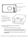
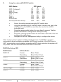
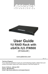
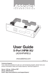
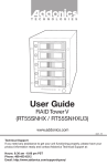
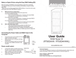
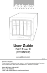
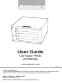
T E C H N O L O G I E S
User Guide
Compact RAID
(CPR5SA)
www.addonics.com
v5.1.11
Technical Support
If you need any assistance to get your unit functioning properly, please have your
product information ready and contact Addonics Technical Support at:
Hours: 8:30 am - 6:00 pm PST
Phone: 408-453-6212
Email: http://www.addonics.com/support/query/
Enclosure Overview
HD0 - HD4
Lock Mechanism
Power LED
HD0 – HD4 Button Functions:
A.
Push-Open Button
Press button for each drive slot to open the front HDD panel.
If the locking mechanism is set to LOCK position, the button
cannot be pressed. Put the locking mechanism to UNLOCK
position to be able to press the push-open button and open the
front HDD panel.
B.
Drive Activity LED
Power LED
Action
Light On
Light On
Light Off
Message
Power starting
System is ready
Power is OFF
Color
Blue
Purple
No
Drive Activity LED
Light On
Light Off
Light On
Flash
Hard drive installed
Hard drive uninstalled
Hard drive fail
Hard drive access
Blue
No
Red
Blue
Power Switch
A.
Power switch / Buzzer disable button
a.
Buzzer disable: press button less than 2 seconds
b.
Power switch: press button over 2 seconds
B.
Reset Device / Change Mode button
a.
Reset Device: press button less than 2 seconds
b.
Change Mode: press button over 2 seconds
www.addonics.com
Technical Support (M-F 8:30am - 6:00pm PST)
Phone: 408-453-6212
Email: www.addonics.com/support/query/
Power Switch / Buzzer Disable Button
Reset Device / Change Mode Button
RAID Setting Dip Switch
eSATA Connection
Power Connector
Installation Guide
1. To open the front panel,
press the push-open button.
2. Slide the 2.5” SATA hard
drive into the slot. Push back
the front panel.
Two Options for Setting RAID on the Compact RAID Box
(only select one option)
I.
Using the JMicron HW RAID Manager utility program
For Windows users, install the JMicron HW RAID Manager located on the
SATA Controller CD. In the CD, go to RAID utilities > JMB393. This
manager can be used to create and monitor the status of the RAID volume.
Use the RESERVE DIP switch setting when using the JMicron HW
RAID Manager.
www.addonics.com
Technical Support (M-F 8:30am - 6:00pm PST)
Phone: 408-453-6212
Email: www.addonics.com/support/query/
II.
Using the onboard RAID DIP switch
RAID Status
RAID 0 (stripped)
RAID 10
JBOD (Large)
RAID 3
Clone
RAID 5
RESERVED
Normal (Individual drives)
a.
b.
c.
d.
e.
DIP Switch
1
2
ON
ON
ON
ON
ON
OFF
ON
OFF
OFF
ON
OFF
ON
OFF
OFF
OFF
OFF
3
ON
OFF
ON
OFF
ON
OFF
ON
OFF
Select the setting desired using the DIP switch table.
Using the provided eSATA to eSATA cable, connect one end to the
eSATA port on the RAID box and the other end to the eSATA
controller card.
Press the power switch button for more than 2 seconds. Wait for
power LED status to change from starting to ready.
Press the “Change mode” button for more than 2 seconds. This will
configure the raid volume.
Navigate to the Disk Management utility to configure the drives.
Note: for the system to detect multiple individual drives, the RAID box must be
connected to a port multiplier compatible eSATA host controller. If the RAID box is
NOT connected to a port multiplier compatible eSATA host controller, the system will
only detect one drive and that is the hard drive in slot HD0.
RAID Monitoring LED
RAID Status
RAID 10
RAID 3
RAID 5
Clone
JBOD (Large)
RAID 0
www.addonics.com
LED Indicator
Access
Rebuilding
Access
Rebuilding
Access
Rebuilding
Access
Clone
Access
Access
Blue / Flash
Blue & Red / Flash
Blue / Flash
Blue & Red / Flash
Blue / Flash
Blue & Red / Flash
Blue / Flash
Blue & Red / Flash
Blue / Flash
Blue / Flash
Technical Support (M-F 8:30am - 6:00pm PST)
Phone: 408-453-6212
Email: www.addonics.com/support/query/