1
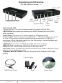
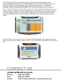
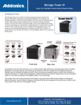
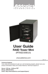
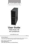
T E C H N O L O G I E S
User Guide
External Port Multiplier Ultra
(AD5EHPMEU3)
www.addonics.com
v8.1.11
Technical Support
If you need any assistance to get your unit functioning properly, please have your
product information ready and contact Addonics Technical Support at:
Hours: 8:30 am - 6:00 pm PST
Phone: 408-453-6212
Email: http://www.addonics.com/support/query/
Unpacking and Overview
D1 – D5: Refers to Device 1 - 5
Power LED
eSATA Device Port
Host
LED
USB
3.0
SET
Power
to host eSATA
Button
input
Host
Dipswitch (SW1) Power
on/off
Drive Activity LED:
LED will light up. If the drive is being accessed, the green LED will blink.
eSATA Ports:This is where you connect your eSATA devices (like your eSATA
drive enclosure)
Power input: Connects to 5V Power supply or USB power cable.
Power on/off: This turns the port multiplier ON or OFF. When the power switch
is in the OFF position, the port multiplier will be powered by a USB host, if
connected. When the power switch is in the ON position, the port multiplier will
be powered by the power input.
eSATA Host: Connects to eSATA controller card on a computer.
USB 3.0 Host: Connects to USB 2.0 or 3.0 port on a computer.
NOTE: Do not connect USB and eSATA at the same time.
Host LED: Glows to indicate an active connection from USB or eSATA to a host
adapter, blinks to indicate activity.
Dipswitch and SET Button: Used to control the Port Multiplier RAID Mode
setting.
Power Supply
USB Power Cable
www.addonics.com
Driver Disk
Technical Support (M-F 8:30am - 6:00pm PST)
Phone: 408-453-6212
Email: www.addonics.com/support/query/
Port Multiplier Compatibility
When configured as a set of individual drives and connected to a SATA or an
eSATA host adapter, the Port Multiplier will only work with a Port Multiplier aware
host. This includes setting up the unit with more than one array. Identify your host
controller and check with its hardware manufacturer if you are unsure. Addonics
offers several Port Multiplier aware host adapters.
Using identical drives for all settings other than JBOD or LARGE is strongly
recommended. Creating a LARGE array using drives that have different properties will use all space on all members, and performance will match that of the
member in use during any particular I/O operation. Creating a RAID using drives
that are not all the same size will result in all members using only as much space
as the smallest member. Creating a RAID using drives that have different performance will degrade the overall performance of the array.
Port Multiplier Modes
JBOD Mode (Individual Drives)
Number of drives: at least 1
Unit capacity: N/A (100% of each individual drive)
Spares: no
Fault tolerance: none
JBOD mode offers all connected units to the host adapter, no RAID is defined at
all.
NOTE: JBOD mode requires a SATA controller featuring Port Multiplier support for
eSATA connections.
NOTE: Optical drives can only be configured as JBOD using an eSATA connection.
RAID 0 (Stripe set)
Number of drives: at least 2
Unit capacity: size of each member times number of members.
Spares: no
Fault tolerance: none - if any member is lost all data is lost.
RAID 0 “stripes” the file system across the array by placing “chunks” of data
sequentially between drives in a specific order.
RAID 1 or 10 (Mirror set, Stripe of mirror sets)
Number of drives: 2 (RAID 1) or 4 (RAID 10).
Unit capacity: size of one member (RAID 1) or size of two members (RAID 10).
Spares: yes – if EZ mode is not disabled and 3 (RAID 1) or 5 (RAID 10) drives are
present, the array will be initialized with a spare.
Fault tolerance: RAID 1 can withstand the loss of one drive without losing data.
RAID 10 can withstand the loss of one drive from each mirror set without losing
data.
RAID 1 works by duplicating the exact same data on two drives.
RAID 10 works by using two RAID 1 sets configured as members of a RAID 0.
Disks 1 and 2 are mirrored, disks 3 and 4 are mirrored, and the two mirror sets
are striped together.
www.addonics.com
Technical Support (M-F 8:30am - 6:00pm PST)
Phone: 408-453-6212
Email: www.addonics.com/support/query/
RAID 3 (Stripe set with dedicated parity)
Number of drives: at least 3
Unit capacity: size of one member times number of members minus one.
Spares: yes
Fault tolerance: can withstand the loss of one drive without losing data.
RAID 3 works by striping data for individual I/O blocks across all members
except one, which contains parity data for the stripe set computed internally by
the Port Multiplier. In the event of failure, the missing information can be
calculated using the parity information.
RAID 5 (Stripe set with striped parity)
Number of drives: at least 3
Unit capacity: size of one member times number of members minus one.
Spares: yes
Fault tolerance: can withstand the loss of one drive without losing data.
RAID 5 works by striping entire I/O blocks across all members of the set, with
each member taking turns carrying parity data computed by the Port Multiplier.
In the event of failure, the missing information can be calculated using the
parity information.
CLONE (Mirror set)
Number of drives: at least 2
Unit capacity: size of one member.
Spares: yes
Fault tolerance: can withstand the loss of any number of drives without losing
data as long as at least one complete member remains online. CLONE mode
works the same way as RAID 1, by maintaining a complete copy of the entire
set of data on each drive.
LARGE (Spanned set)
Number of drives: at least 2
Unit capacity: 100% of all drives together regardless of differences in size
Spares: no
Fault tolerance: cannot withstand the loss of any drives without losing data.
However, some data may be recovered as long as the drive(s) carrying the file
system data (boot record, directory, etc.) remain online. LARGE mode is
neither a RAID nor is it a JBOD. It works by declaring the sum of all available
space of the member drives as a single unit, without striping the data. As each
member is filled, new data is stored on the next.
Notes about Spare Drives
If EZ mode is disabled (SW1:2 ON), all individual drives not configured as array
members will be offered to the host adapter as separate units.
To create an array with one or more spares, set or modify the RAID mode while
the spares are disconnected from the Port Multiplier. When EZ mode is
enabled (SW1:2 OFF), individual drives connected when an array is present
are considered spare. Spare drives must be equal to or larger in size than the
smallest member. When any type of array is defined, individual units will be
considered spare.
www.addonics.com
Technical Support (M-F 8:30am - 6:00pm PST)
Phone: 408-453-6212
Email: www.addonics.com/support/query/
Configuring the Port Multiplier Using Dipswitches
Resetting the RAID
NOTE: This procedure destroys all RAID data. It should not harm individual drives
or their contents; however, creating backups of all data is strongly recommended
before proceeding.
Be sure the port multiplier is connected to an active host before proceeding. The
port multiplier will not complete the process if it has no host connection.
1. Power down the unit and set the dip switch to the desired RAID Mode.
2. While holding the SET button, turn the unit on. A long beep will sound from the
Port Multiplier. The SET button may be released once the long beep starts.
Shortly after releasing the SET button, the port multiplier should “chirp” to indicate
the process is complete. If instead of a chirp the Port Multiplier sounds a series of
short beeps, an error has occurred during the process.
Setting or Modifying the RAID Mode
NOTE: Setting or modifying the RAID mode destroys all data.
Be sure the port multiplier is connected to an active host before proceeding. The
port multiplier will not complete the process if it has no host connection.
1. Follow the procedure for resetting the RAID Mode.
2. Power down the unit and set the dip switch to the desired RAID Mode.
3. While holding the SET button with a ballpoint pen, turn the unit on. A long beep
will sound from the Port Multiplier. The SET button may be released once the long
beep starts.
Shortly afterward, the port multiplier should “chirp” to indicate the process is
complete. If instead of a chirp the Port Multiplier sounds a series of short beeps, an
error has occurred during configuration of the array.
BZS Switch (SW1:1):
The BZS switch is used to silence the audible alarm buzzer. The OFF position
permits the audible alarm, and the ON position silences the audible alarm. The
BZS switch has immediate effect.
EZ Switch (SW1:2):
The EZ (spare) switch inhibits spares when ON. When in the OFF position, all
individual drives (not defined as members of an array) are considered spare and
are not offered to the operating system. Should a RAID become degraded, when
the EZ switch is in the OFF position a spare drive will be used automatically to
rebuild the RAID, if present. EZ mode is determined when the unit is powered up.
Changing the switch will have no effect until the unit has been re-powered.
Warning: turning off the EZ switch to rebuild an array will consider any drives not
declared array members to be eligible for rebuild as a spare. Rebuilding will
destroy all existing data on that drive and the drive chosen is not predictable.
Disconnect any individual drives with valuable data on them before enabling EZ
Mode.
www.addonics.com
Technical Support (M-F 8:30am - 6:00pm PST)
Phone: 408-453-6212
Email: www.addonics.com/support/query/
RAID Mode Switches M2, M1, M0 (SW1:3 – SW1-5)
The RAID Mode switches define what type of RAID will be initialized when the
unit is powered up while the RAID Mode button is held down. Each type of RAID
has different properties and requirements, as follows:
Dipswitch Position
JBOD (Individual
Drives)
* FACTORY
DEFAULT SETTING
RAID 0
1 (BZS)
OFF
RAID 1 OR 10
RAID 3
RAID 5
CLONE
LARGE
OFF
OFF
OFF
OFF
OFF
OFF
1
2 (EZ)
3 (M2)
4 (M1)
5 (M0)
OFF
OFF
OFF
ON
ON
ON
ON
OFF
OFF
OFF
OFF
ON
ON
ON
OFF
OFF
ON
ON
OFF
ON
ON
OFF
OFF
OFF
OFF
ON
ON
OFF
2
3
NOTES:
1. Audible Alarm is recommended at all times.
2. EZ mode has no effect when no array is defined.
3. Disabling EZ for RAID 0 and LARGE is strongly recommended.
Configuring the Port Multiplier Using the JMicron RAID Manager
Windows users may install the JMicron HW RAID Manager application located
on the SATA Controller CD, or download it from
http://addonics.com/drivers/driver_list.php. In the CD, browse to Configuration
Utilities → JMB393.
Mac and Linux users may download those versions of the same utility from
http://addonics.com/drivers/driver_list.php under “Port Multiplier & Hub.” The
JMicron RAID Manager can be used to create, modify, and monitor the health
status of the RAID drives, and provide status alerts with dialog boxes and even
email. When configuring the RAID mode using the RAID Manager application, it
is strongly recommended to leave the dip switch in the factory default setting.
Setting or Modifying the RAID Mode
This procedure briefly describes the steps for using the Jmicron RAID Manager's Basic Mode to create an array. The example shown is a LARGE set.
There are other options available in the Advanced Modes, including building
arrays using specified drives, setting up email notifications, and updating the
firmware – which are not discussed in this user guide.
After starting the Jmicron RAID Manager, the first screen will show the status of
any Port Multipliers detected and any drives connected. Shown below is a Port
Multiplier with a variety of five drives connected:
On the left pane is “Controller 1” which is the first port multiplier detected by the
software. Shown in a tree view are the five drives, listed as P0-P4. These are
currently individual drives. On the right pane is a listing of the drives and below
that is a graphical view of each drive. “Disk 1” through “Disk 4” indicate which
physical port the drive is connected to. For the AD5HPMSXA, AD5HPMRXA-E,
and AD5HPMREU this refers to ports P0-P4. On the CPR5SA unit, this refers to
HD0-HD4. On the AD5EHPMEU3 this refers to D1-D5. On RAID Tower products
this relates to the drives mounted left to right or top to bottom, except in cases
where a drive map is included showing otherwise.
www.addonics.com
Technical Support (M-F 8:30am - 6:00pm PST)
Phone: 408-453-6212
Email: www.addonics.com/support/query/
Next, click the Basic RAID Configuration tab and select the type of RAID desired.
Note that RAID 1 is currently disabled as an option since more than two
individual drives are available, and DELETE ALL RAID is disabled since there are
currently no arrays to delete. Shown below is the same set of drives being
selected as a LARGE array.
Finally, click Apply. The Jmicron RAID Manager will confirm the operation with a
reminder that existing data on the drives will be lost, then perform the RAID
configuration and report with a dialog box when it is complete.
www.addonics.com
Technical Support (M-F 8:30am - 6:00pm PST)
Phone: 408-453-6212
Email: www.addonics.com/support/query/
The RAID and Disk Information screen (shown when the program was
launched) will now show the Port Multiplier with an Array. The drives are now
listed as M0-M4, indicating they are members of the array. If spares are
present (individual drives added later, and the EZ switch is in the OFF
position), they would be listed as S0, S1, etc. On the right pane, the RAID
Level, status, capacity and members that are online are listed. Status will show
“Normal” (all members on line), “Degraded” (a fault-tolerant array with a drive
failure needing service), “Rebuilding” (a fault-tolerant array in the process of
reconstructing lost data onto a spare) or “Broken” (an array that has lost all
data).
In the event of a drive failure, the Jmicron RAID Manager will present a dialog
box such as the one shown below, even if it is currently minimized to the system
tray:
CONTACT US
www.addonics.com
Phone:
Fax:
Email:
408-573-8580
408-573-8588
http://www.addonics.com/sales/query/