1
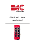
IE-iMcV-T1/E1/J1-LineTerm
SFP and 1x9
Operation Manual
Above illustration is representative; different models available
FCC Radio Frequency Interference Statement
This equipment has been tested and found to comply with the limits for a Class A computing device, pursuant to Part 15 of the FCC Rules.
These limits are designed to provide reasonable protection against harmful interference when the equipment is operated in a commercial
environment. This equipment generates, uses and can radiate radio frequency energy and, if not installed and used in accordance with the
instruction manual, may cause harmful interference to radio communications. Operation of this equipment in a residential area is likely to
cause harmful interference in which the user will be required to correct the interference at his own expense.
Any changes or modifications not expressly approved by the manufacturer could void the user’s authority to operate the equipment.
The use of non-shielded I/O cables may not guarantee compliance with FCC RFI limits. This digital apparatus does not exceed the Class A
limits for radio noise emission from digital apparatus set out in the Radio Interference Regulation of the Canadian Department of
Communications.
Le présent appareil numérique n’émet pas de bruits radioélectriques dépassant les limites applicables aux appareils numériques de classe A
prescrites dans le Règlement sur le brouillage radioélectrique publié par le ministère des Communications du Canada.
Warranty
IMC Networks warrants to the original end-user purchaser that this product, EXCLUSIVE OF SOFTWARE, shall be free
from defects in materials and workmanship under normal and proper use in accordance with IMC Networks' instructions
and directions for a period of six (6) years after the original date of purchase. This warranty is subject to the limitations set
forth below.
At its option, IMC Networks will repair or replace at no charge the product which proves to be defective within such
warranty period. This limited warranty shall not apply if the IMC Networks product has been damaged by unreasonable
use, accident, negligence, service or modification by anyone other than an authorized IMC Networks Service Technician
or by any other causes unrelated to defective materials or workmanship. Any replaced or repaired products or parts carry
a ninety (90) day warranty or the remainder of the initial warranty period, whichever is longer.
To receive in-warranty service, the defective product must be received at IMC Networks no later than the end of the
warranty period. The product must be accompanied by proof of purchase, satisfactory to IMC Networks, denoting
product serial number and purchase date, a written description of the defect and a Return Merchandise Authorization
(RMA) number issued by IMC Networks. No products will be accepted by IMC Networks which do not have an RMA
number. For an RMA number, contact IMC Networks at PHONE: (800) 624-1070 (in the U.S. and Canada) or (949) 4653000 or FAX: (949) 465-3020. The end-user shall return the defective product to IMC Networks, freight, customs and
handling charges prepaid. End-user agrees to accept all liability for loss of or damages to the returned product during
shipment. IMC Networks shall repair or replace the returned product, at its option, and return the repaired or new
product to the end-user, freight prepaid, via method to be determined by IMC Networks. IMC Networks shall not be
liable for any costs of procurement of substitute goods, loss of profits, or any incidental, consequential, and/or special
damages of any kind resulting from a breach of any applicable express or implied warranty, breach of any obligation
arising from breach of warranty, or otherwise with respect to the manufacture and sale of any IMC Networks product,
whether or not IMC Networks has been advised of the possibility of such loss or damage.
EXCEPT FOR THE EXPRESS WARRANTY SET FORTH ABOVE, IMC NETWORKS MAKES NO OTHER WARRANTIES,
WHETHER EXPRESS OR IMPLIED, WITH RESPECT TO THIS IMC NETWORKS PRODUCT, INCLUDING WITHOUT
LIMITATION ANY SOFTWARE ASSOCIATED OR INCLUDED. IMC NETWORKS SHALL DISREGARD AND NOT BE
BOUND BY ANY REPRESENTATIONS OR WARRANTIES MADE BY ANY OTHER PERSON, INCLUDING EMPLOYEES,
DISTRIBUTORS, RESELLERS OR DEALERS OF IMC NETWORKS, WHICH ARE INCONSISTENT WITH THE WARRANTY
SET FORTH ABOVE. ALL IMPLIED WARRANTIES INCLUDING THOSE OF MERCHANTABILITY AND FITNESS FOR A
PARTICULAR PURPOSE ARE HEREBY LIMITED TO THE DURATION OF THE EXPRESS WARRANTY STATED ABOVE.
Every reasonable effort has been made to ensure that IMC Networks product manuals and promotional materials
accurately describe IMC Networks product specifications and capabilities at the time of publication. However, because of
ongoing improvements and updating of IMC Networks products, IMC Networks cannot guarantee the accuracy of printed
materials after the date of publication and disclaims liability for changes, errors or omissions.
ii
Table of Contents
FCC Radio Frequency Interference Statement ....................................................ii
Warranty............................................................................................................ii
About the IE-iMcV-T1/E1/J1-LineTerm................................................................1
Installing an iMcV-Module .................................................................................2
Crossover/Straight-Through Connection..............................................................2
Configuration .....................................................................................................2
Prerequisites ......................................................................................................2
Managed Modules .............................................................................................3
Configuration Control ........................................................................................4
Unmanaged Modules.........................................................................................5
DIP Switches......................................................................................................6
DIP Switch Settings (S2, S3)................................................................................7
Features .............................................................................................................9
LED Operation.................................................................................................13
Loopback Testing .............................................................................................14
Pseudorandom Bit Sequence (PRBS) Testing ....................................................15
Installation Troubleshooting .............................................................................15
Specifications ...................................................................................................17
IMC Networks Technical Support.....................................................................17
Fiber Optic Cleaning Guidelines.......................................................................18
Electrostatic Discharge Precautions...................................................................19
Certifications....................................................................................................20
iii
About the IE-iMcV-T1/E1/J1-LineTerm, TP/SFP
NOTE
Unless noted otherwise, any reference is applicable for both the 1x9 and SFP version of
the IE-iMcV-T1/E1/J1-LineTerm in this manual.
IE-iMcV-T1/E1/J1-LineTerm, TP/SFP is an SNMP-Manageable module that converts
standard TDM-based copper transports (T1, E1, J1) to a single-mode or multi-mode
fiber signal. It performs a standard “Line Termination” function as defined in GR820-CORE. This function transmits an Alarm Indication Signal (AIS) on the line
whenever the received signal is lost. Line faults can easily be isolated to one line
section and do not propagate over multiple-line sections as they do with normal line
repeaters.
Each module includes one RJ-48 connector, one pair of ST or SC fiber optic
connectors or an SFP port, which can support any fiber type at 155Mbps; dual strand
available in LC connectors, and Single Strand Fiber SFPs available in SC connectors.
IE-iMcV-T1/E1/J1-LineTerm, TP/SFP modules install into any modular, SNMP
manageable iMediaChassis, as well as the MediaChassis series, which is unmanaged.
The IE-iMcV-T1/E1/J1-LineTerm, TP/SFP offers an extended temperature range of
-40°C to +85°C; when installed in an IE-MediaChassis/1 or 2, available in AC and
DC, the module can be installed in challenging heat or cold-related environments.
An IE-iMcV-T1/E1/J1-LineTerm, TP/SFP with SFP Module with Configuration Control,
configured as a Host, allows an SNMP Management Module in a managed chassis to
manage the Remote. All settings are enabled and enforced through the SNMP. The
Host keeps a copy of the Remote’s configuration settings. Each module offers the
feature Configuration Control; please refer to the appropriate section.
When the Host unit is not in a managed chassis, the Host configures the Remote. This
ensures that the Remote’s configuration will not revert to its DIP Switch settings and
potentially disrupt traffic. However, if the user changes the DIP Switch settings on the
Remote, the new configuration of the Remote will be enabled.
When SNMP management is installed at the Host, the following functions at the
Remote are controlled from the Host unit:
•
•
•
•
Loopback
Line Code
Transmit Data Source
Fault Loopback
The IE-iMcV-T1/E1/J1-LineTerm, TP/SFP with SFP Host unit can also display the
DDMI information from the Remote LineTerm module. Please download the latest
SNMP Management Module firmware and iVIew² software to ensure the full support
and functionality of the modules.
1
NOTE
IE-iMcV-T1/E1/J1-LineTerm, TP/SFP with SFP Module can be installed in an iMediaChassis
and MediaChassis series.
Installing an iMcV-Module
iMcV-Modules install in IMC Networks’ SNMP manageable iMediaChassis series or in
any MediaChassis/IE-MediaChassis series.
To install an iMcV-Module:
1.
Remove the blank bracket covering the slot where the module is to be installed
by removing the screws on the outside edges of the bracket.
2.
Slide the iMcV-Module into the chassis, via the cardguides, until the module is
seated securely in the connector.
3.
Secure the module to the chassis by tightening the captive screw.
4.
Save any “blanks” removed during installation for future use if the configuration
requirements change.
NOTE
All modules are hot-swappable
Crossover/Straight-Through Connection
IE-iMcV-T1/E1/J1-LineTerm, TP/SFP comes with an RJ-48 UTP connector that features
a push-button switch, located next to the port, for selecting a crossover connection,
push-button IN. A straight-through connection is selected when the push-button is
OUT. When unsure what type of connection is needed, set the push button to the
position that turns the LOS LED off.
Configuration
Proper configuration of the IE-iMcV-T1/E1/J1-LineTerm, TP/SFP is required for
maximum performance and reliability. The following sections describe the
prerequisites and the configurations available for both managed and unmanaged
modules.
Prerequisites
The IE-iMcV-T1/E1/J1-LineTerm, TP/SFP conforms to any T1/E1/J1-based
environment. Ensure all of the relevant information about the expected installation
environment is available before configuring the module. This information includes:
• Line Type T1 or E1
• Line Coding used on T1: either AMI or B8ZS
• Distance of the copper run for DSX1 lines (655 feet MAX)
2
• Required CSU line Buildout (0db to -22db)
• Receiver BOOST for T1 and E1 applications
• Fiber transceivers must be for appropriate fiber run, i.e. (SM or MM)
• Management location must be at HOST unit
Managed Modules
The IE-iMcV-T1/E1/J1-LineTerm, TP/SFP modules are installed as a HOST-REMOTE
pair and can be remotely managed when the HOST is installed in an iMediaChassis
with an SNMP Management module.
For a managed environment, first manually configure the desired features through
DIP Switch settings to ensure this configuration is maintained if management is ever
lost. After the module is installed, the SNMP enabled features for troubleshooting
can be modified by using the included iView2 SNMP management software. Ensure
the software settings match the desired configuration requirements for the installation
as the chassis may maintain an old setting from a previous installation for that slot
location. Module Details will provide information such as serial number, date code
and part number. Please download the current SNMP firmware and iView2 software
to ensure all functionality of the modules.
NOTE
If installing an IE-iMcV-T1/E1/J1-LineTerm, available in a fixed fiber transceiver model (series
850-141XX), as a Host and an IE-iMcV-T1/E1/J1-LineTerm with SFP and Configuration Control
(850-18100) as a Remote, connectivity will be established and data will pass. However, there
is no possibility of obtaining DDMI information of the SFP from the Remote end, since the
Host is not capable of it. If the Host and the Remote units are both IE-iMcV-T1/E1/J1LineTerm with SFP and Configuration Control, then the Host can extract DDMI information
from the SFP at the Remote end.
3
Configuration Control
Some iMcV-Modules offer configuration control; labels on the front faceplate are
identified as such. Configuration control has been implemented to assist the end user
by retaining the latest configuration regardless of how that configuration was
implemented (via DIP Switch settings or SNMP).
Historically, SNMP would override DIP Switch settings. If changes are made to the
module via iView2, the SNMP settings determine the configuration of the board and
the DIP Switches had no effect. Configuration control enables the user to use iView2
or DIP Switches to modify the configuration.
With configuration control, the end user has three conditions under which the
configuration of the iMcV-Module with Configuration Control may be impacted:
•
•
•
Installing an IE-iMcV-T1/E1/J1-LineTerm, TP/SFP into a chassis already loaded
with iMcV-Modules or replacing an IE-iMcV-T1/E1/J1-LineTerm, TP/SFP
- The iMcV-Module will transfer its saved configurations. The IE-iMcVT1/E1/J1-LineTerm, TP/SFP will not override the module’s configuration.
Replacing the same type of iMcV-Module
- If the DIP Switch settings are the same as the settings on the removed iMcVModule, the IE-iMcV-T1/E1/J1-LineTerm, TP/SFP determines the
configuration settings through the chassis's management.
- If the DSW are different, then the configuration of the module is
determined by the DIP Switch settings. (The settings are forwarded to the
chassis's management module and the value is saved.)
Installing a new model of iMcV-Module
- If another type of module is installed into the same slot in a chassis, the IEiMcV-T1/E1/J1-LineTerm, TP/SFP clears the memory of the previous
configuration for that slot; the settings of a new module are adopted and
stored in the IE-iMcV-T1/E1/J1-LineTerm, TP/SFP.
The SNMP Write Lock switch does not impact any iMcV-Module or IE-iMcV-Module
with Configuration Control. Removing and installing a new SNMP Management
Module will no longer impact these modules either. However, if there is a mixture of
iMcV-Modules with and without Configuration Control, the Write Lock Switch and a
new SNMP Management Module must be taken into consideration.
If the command cleandb is applied to an SNMP Management Module, all the settings
for the modules will be removed, but the Configuration Control modules will still be
based on the last change made, while those without Configuration Control will be set
to their default settings.
4
NOTE
If the end user has a mixture of standard iMcV-Modules as well as Configuration Control
iMcV-Modules, it is important to understand how SNMP and DIP Switches will impact the
cards depending on their capability. Standard iMcV-Modules cannot be upgraded to
Configuration Control capability, so it is strongly recommended to set the DIP Switches on
the modules and then configure them via software to match the same settings.
iView² Management Software
iView² is the IMC Networks management software designed specifically for the IMC
Networks “iMcV” family of modules. It features a GUI and gives network managers
the ability to monitor and control the manageable IMC Networks products.
iView² is available in several versions, including WebServer version 3.0, and can also
function as a snap-in module for HP OpenView Network Node Manager and other
third party SNMP Management software. For assistance in selecting the right version
of iView² for your operating system, please visit:
http://www.imcnetworks.com/products/iview2.cfm
iView2 supports the following platforms:
• Windows 2000
• Windows XP
• Windows Vista
• Windows 7
Please see the SNMP Management Module installation guide for software
configuration options.
Unmanaged Modules
Before installing the module in an unmanaged chassis, manually configure all of the
desired DIP Switch selectable features. Refer to Tables on page 7 and 8.
Modules must be configured as a HOST-REMOTE pair via DIP Switches. Modules
are shipped in the default setting as a HOST.
HOST:
S3-2 OFF
REMOTE:
S3-2 ON
5
DIP Switches
The IE-iMcV-T1/E1/J1-LineTerm, TP/SFP DIP Switches are located on S2 and S3 on
the PCB. The location of the S2 and S3 DIP Switches are displayed in the following
diagram:
6
DIP Switch Settings (S2, S3)
Switch Settings for Switch S2
T1/E1 Selection
S2-1: OFF
S2-1: ON
T1 Mode Selected
E1 Mode Selected
default
Receive Equalizer Gain Limit (EGL)
iVIEW2
iVIEW2
iVIEW2
iVIEW2
iVIEW2
iVIEW2
E1
S2-2: ON -12 dB (Short Haul)
S2-2: OFF -43 dB (Long Haul)
T1
S2-2: ON -36 dB (Long Haul)
S2-2: OFF -30 dB (Limited Long Haul)
default
iVIEW2
Line Encoding iVIEW2
S2-3: ON HDB3 (E1) / B8ZS (T1)
S2-3: OFF AMI (Required for Passive Mode)
iVIEW2
iVIEW2
default
Transmit LIU Waveshape (Build-out)
SWITCH S2
E1
S2-4: ON
S2-4: OFF
S2-4: ON
S2-4: OFF
S2-5: ON
S2-5: ON
S2-5: ON
S2-5: ON
S2-6: ON
S2-6: ON
S2-6: OFF
S2-6: OFF
75 ohms
125 ohms
75 S ohms w/ High Return Loss
125 S ohms w/ High Return Loss
S2-4: ON
S2-4: OFF
S2-4: ON
S2-4: OFF
S2-4: ON
S2-4: OFF
S2-4: ON
S2-4: OFF
S2-5: ON
S2-5: ON
S2-5: OFF
S2-5: OFF
S2-5: ON
S2-5: ON
S2-5: OFF
S2-5: OFF
S2-6: ON
S2-6: ON
S2-6: ON
S2-6: ON
S2-6: OFF
S2-6: OFF
S2-6: OFF
S2-6: OFF
DSX-1 (0 to 133 ft) 0 dB CSU
DSX-1 (133 to 266 ft)
DSX-1 (266 to 399 ft)
DSX-1 (399 to 533 ft)
DSX-1 (533 to 655 ft)
-7.5 dB CSU
-15 dB CSU
-22.5 dB CSU
T1
default
Receive LIU Termination
S2-7: ON
S2-7: OFF
S2-7: ON
S2-7: OFF
S2-8: ON
S2-8: ON
S2-8: OFF
S2-8: OFF
Receive Side Termination Disabled
Receive Side 120 ohms Enabled
Receive Side 100 ohms Enabled
Receive Side 75 ohms Enabled
default
Transmit Data Source iVIEW2
S2-9: ON
S2-9: OFF
S2-9: ON
S2-9: OFF
S2-10: ON
S2-10: ON
S2-10: OFF
S2-10: OFF
Standard Data
Transmit Pseudorandom Bit Sequence (PRBS)
Transmit Alternating Ones and Zeros
Transmit Unframed All Ones
7
iVIEW2
iVIEW2
iVIEW2
iVIEW2
default
Switch Settings for Switch S3
Reserved
S3-1: ON
S3-1: OFF
Reserved
Reserved
default
Remote Management
S3-2: ON
S3-2: OFF
Remote Management Enabled (only at the REMOTE end)
Remote Management Disabled (only at the LOCAL end)
default
SWITCH S3
Loopback Selection iVIEW2
S3-3: ON
S3-3: OFF
S3-3: ON
S3-3: OFF
S3-4: ON
S3-4: ON
S3-4: OFF
S3-4: OFF
None
Fiber Analog Loopback
Internal Fiber Loopback
Copper Remote Loopback
iVIEW2
iVIEW2
iVIEW2
iVIEW2
default
Monitor/Boost Mode
S3-5: ON
S3-5: OFF
S3-5: ON
S3-5: OFF
S3-6: ON
S3-6 ON
S3-6 OFF
S3-6 OFF
Normal Operation (No Boost)
20 dB
26 dB
32 dB
default
Fault Loopback
S3-7: ON
S3-7: OFF
Send AIS is sent back toward the fault on the RJ-45 port
AIS is only sent toward the fiber on detecting a fault on the
RJ-45 port
Fiber Type
S3-8: Factory Configured
S3-9: Factory Configured
S3-10: Factory Configured
DO NOT CHANGE
DO NOT CHANGE
DO NOT CHANGE
8
iVIEW2
iVIEW2
default
Features
The IE-iMcV-T1/E1/J1-LineTerm, TP/SFP module includes several features to facilitate
maintenance and troubleshooting in any T1/E1/J1 based TDM environment.
SFP
SFPs with Data and Diagnostics Management Information (DDMI) can be installed in
the SFP port of the host and the remote. This allows the end user to view the DDMI
information through the chassis's management using the SFP button in iView2.
9
Loopback Modes
This feature allows three distinct Loopbacks to be activated either through DIP
Switches or iView2 Management.
Fiber
Loopback
An analog Loopback at the copper port back to the fiber port. It
copies the received optical signal back to the optical line at the
copper port and continues to drive the copper port, but can be
corrupted by noise on the copper port.
Internal
Fiber
Loopback
A local Loopback at the fiber port. It copies the received optical
signal back to the optical line at a digital point internal to the unit.
It continues to drive the copper port, and normal copper line
monitoring is maintained on the copper port, but the returning
data pattern is not affected.
Copper
Loopback
A remote Loopback to copper port at the fiber driver. It copies
the received copper signal back to the copper port and continues
to drive the fiber port.
By default all Loopbacks are set to OFF for normal data operation.
The following illustrations show the path that a signal takes in each of the Loopback
test modes.
This feature can be controlled by SNMP–Management software (iView2) when the
HOST IE-iMcV-T1/E1/J1-LineTerm, TP/SFP module is installed in a managed chassis.
10
Fault Loopback
This switch enables or disables the Fault Loopback feature on the copper port. A
normal copper line LOS fault will cause a Remote Alarm Indictor (RAI) to be sent on
to the fiber line segment causing the normal AIS to be sent on the far end copper
port. The fault loopback feature provides for a fault indication to be sent back to the
copper line as an AIS signal. In this way, both upstream and downstream personnel
are alerted to a copper cable fault.
The Fault Loopback feature is always active on the fiber line. When a fiber line
becomes unavailable, the module detects the LOS on the fiber link and lights the
LOS LED. The module then sends AIS to the local copper port and sends a RAI signal
back to the fiber. The far end unit turns ON the RAI LED and outputs AIS to the far
end copper line. With this, a local site administrator can quickly determine where a
fiber fault is located from either end of the fiber line.
The AIS is transmitted as an unframed all ones pattern on the copper port.
The default loopback DIP Switch is disabled by default.
This feature can be controlled by SNMP-Management software (iView2) when the
HOST IE-iMcV-T1/E1/J1-LineTerm, TP/SFP module is installed in a managed chassis.
Transmit LIU Waveshape and Gain (Line Build-Out)
This group of switches can be configured for the length of line the unit is driving, from
0 feet to a maximum of 655 feet. For longer length lines, the unit can be configured
for CSU signal gain to address -7.5 db, -15db, and -22.5 db degraded signals.
By default this feature is set to 0 to 133 feet line Buildout for DSX1 lines.
Transmit Data Source
These switches select the transmit mode used by the IE-iMcV-T1/E1/J1-LineTerm,
TP/SFP module. The transmit modes that can be selected include the following:
•
•
•
•
Standard data
Unframed All Ones (diagnostic)
Alternating Ones and Zeros (diagnostic)
Pseudorandom Bit Sequence Pattern for T1 and 215-1 PRBS Pattern for E1)
These standard Telco transmission pattern modes are provided to help diagnose
transmission errors in the line.
By default this feature is set to Standard Data.
This feature can be controlled by SNMP-Management software (iView2) when the
HOST IE-iMcV-T1/E1/J1-LineTerm, TP/SFP module is installed in a managed chassis.
11
T1, E1 and J1 Selection
This switch selects the data rate to use on the copper line. The data rate selections
available include the following:
•
•
T1/J1 (1.544 Mbps +/- 32 ppm)
E1 (2.048 Mbps +/- 32 ppm)
By default this feature is set to T1.
This feature can be selected only by setting the DIP Switches manually.
Remote Management
A DIP Switch enables or disables the Remote Management mode. By default this
feature is Disabled. Remote Management must be enabled on the REMOTE module.
This allows all SNMP-configurable features for the REMOTE modules to be configured
from the HOST module.
An IE-iMcV-T1/E1/J1-LineTerm w/SFP Module with Configuration Control, configured
as a Host, allows an SNMP Management Module in a managed chassis to manage
the Remote. All settings are enabled and enforced through the SNMP. The Host
keeps a copy of the Remote’s configuration settings.
When the Host unit is in a managed chassis, the Host configures the Remote. This
ensures that the Remote’s configuration will not revert to its DIP Switch settings and
potentially disrupt traffic. However, if the customer changes the DIP Switch settings
on the Remote, the new configuration of the Remote will be saved by the host.
When SNMP management is installed at the Host, the following functions at the
Remote are controlled from the Host unit:
•
•
•
•
Loopback
Line Code
Transmit Data Source
Fault Loopback
NOTE
IE-iMcV-T1/E1/J1-LineTerm, TP/SFP with SFP Module can be installed in an
iMediaChassis and MediaChassis series. However, there is no support for the module
in the iMediaCenter Series.
12
LED Operation
The IE-iMcV-T1/E1/J1-LineTerm, TP/SFP module features several diagnostic LEDs per
port. The following LED display functions are provided:
Copper Port LEDs
ER
Flashes yellow whenever a line code violation is
received.
LOS
Glows red when the RJ-48 is receiving no signal and is
in an LOS ALARM state. This condition will also send
an RAI signal to the fiber port. If the Fault Loopback is
set to ON, an AIS will also be sent to the local copper
port.
PRBS
Glows green when the copper port receives a valid
Pseudorandom Bit Sequence (PRBS). It is OFF when
the port is not receiving a PRBS.
TEST
Glows yellow when any Loopback mode is active.
Fiber Port LEDs
ER
Glows yellow when a fiber symbol error has been
received.
Glows red when a fiber link is not established and is in
LOS
a LOS ALARM state.
Glows green on the REMOTE unit when Remote
RM
Management is enabled. Glows green on the HOST
unit when it has discovered a manageable REMOTE
unit. Under normal operation this LED is the only LED
that is ON at the unit.
Glows yellow when a Remote Alarm Indication (RAI) is
RAI
received on the fiber port. This indicates a fault exists
at the far end unit.
NOTE
Unless noted otherwise, any reference is applicable for both the 1x9 and SFP version of
the IE-iMcV-T1/E1/J1-LineTerm in this manual.
13
Loopback Testing
The IE-iMcV-T1/E1/J1-LineTerm, TP/SFP includes three Loopback test modes: Copper
Loopback, Fiber Loopback and Internal Fiber Loopback.
The following illustrations show a typical progression of Loopback tests (i.e., starting
by checking the copper segment at the local side, then the fiber segment at the
REMOTE side, etc).
Each Loopback performs the following:
• Copies the incoming signal back out to the origin while continuing to transmit this
signal downstream.
• Blocks upstream data from transmitting on the looped data line.
Loopback testing is useful for troubleshooting problems with network connections
should they occur. Looping received data back onto the transmit path helps
determine whether a connection is still valid. Copper Loopback tests isolate
problems on the copper run between an IE-iMcV-T1/E1/J1-LineTerm, TP/SFP module
and the connected device, while Fiber Loopback tests can isolate problems on the
fiber connected to the module.
14
Pseudorandom Bit Sequence (PRBS) Testing
To test using PRBS, configure the IE-iMcV-T1/E1/J1-LineTerm, TP/SFP modules for No
Loopback, and then configure the Transmit Copper Data Source to PRBS. Configure
the local device for Loopback and start the test. Verify the PRBS LED is ON
indicating no errors are being received.
Installation Troubleshooting
General Troubleshooting
• The copper port can easily be tested using the internal PRBS signal generator and
detector and a physical wire loop on the copper interface.
• The fiber port is internally tested at all times by a working pair of units. With one
unit configured for Local Management (S3-2 set OFF) and the other for Remote
Management (S3-2 set ON), the fiber line is verified if the RM LED is ON at both
ends of the fiber line. Under normal operation only the RM LED is ON at both
HOST and REMOTE.
• To test a media converter by itself, first verify that the fiber patch cable is
appropriate, then follow these steps to test:
1. Connect the media converter to the RJ-48 device with a copper cable.
2. Loop a single strand of fiber from the transmit port to the receive port of the
media converter.
3. Verify that there is a valid connection for both the RJ-48 and fiber ports on the
media converter. (No ER or LOS LED ON)
• If there is trouble with link connectivity, verify that the cable connection and DIP
Switch settings are correct.
15
Use the following LED indications to identify the fault location:
*DIP Switch S3-7 must be set to ON for Fault Loopback to operate as illustrated.
The following table lists the pin configuration for the RJ-48 connector.
Pin
1
2
3
4
5
6
7
8
Signal
Receive Ring
Receive Tip
No Connection
Transmit Ring
Transmit Tip
No Connection
No Connection
No Connection
Pin 1
16
Specifications
Standards Compliance (T1, E1, J1):
ANSI T1.102-1993
ANSI T1.107.1995
GR-820-CORE
T1, E1, J1 Interface:
T1 (1.544 Mbps +/- 32 ppm)
E1 (2.048 Mbps +/- 32 ppm)
J1 (1.544 Mbps +/- 32 ppm)
Power Consumption (Typical):
0.550 Amps @ 5 V
Operating Temperature:
-4°F to +158°F (-20°C to +70°C)
Storage Temperature:
-40°F to +185°F (-40°C to +85°C)
Humidity:
5% to 95% non-condensing
Dimensions:
Single Slot iMcV-Module
IMC Networks Technical Support
Tel: (949) 465-3000 or (800) 624-1070 (in the U.S. and Canada);
+32-16-550880 (Europe)
Fax: (949) 465-3020
E-Mail: [email protected]
Web: www.imcnetworks.com
17
Fiber Optic Cleaning Guidelines
Fiber Optic transmitters and receivers are extremely susceptible to contamination by
particles of dirt or dust, which can obstruct the optic path and cause performance
degradation. Good system performance requires clean optics and connector ferrules.
1.
Use fiber patch cords (or connectors, if you terminate your own fiber) only from
a reputable supplier; low-quality components can cause many hard-to-diagnose
problems in an installation.
2.
Dust caps are installed at IMC Networks to ensure factory-clean optical devices.
These protective caps should not be removed until the moment of connecting
the fiber cable to the device. Should it be necessary to disconnect the fiber
device, reinstall the protective dust caps.
3.
Store spare caps in a dust-free environment such as a sealed plastic bag or box
so that when reinstalled they do not introduce any contamination to the optics.
4.
If you suspect that the optics have been contaminated, alternate between
blasting with clean, dry, compressed air and flushing with methanol to remove
particles of dirt.
18
Electrostatic Discharge Precautions
Electrostatic discharge (ESD) can cause damage to any product, add-in modules or
stand alone units, containing electronic components. Always observe the following
precautions when installing or handling these kinds of products
1.
Do not remove unit from its protective packaging until ready to install.
2.
Wear an ESD wrist grounding strap before handling any module or component.
If the wrist strap is not available, maintain grounded contact with the system unit
throughout any procedure requiring ESD protection.
3.
Hold the units by the edges; do not touch the electronic components or gold
connectors.
4.
After removal, always place the boards on a grounded, static-free surface, ESD
pad or in a proper ESD bag. Do not slide the modules or stand alone units over
any surface.
WARNING! Integrated circuits and fiber optic components are
extremely susceptible to electrostatic discharge damage. Do not
handle these components directly unless you are a qualified
service technician and use tools and techniques that conform to
accepted industry practices.
19
Certifications
CE: The products described herein comply with the Council Directive on
Electromagnetic Compatibility (2004/108/EC)
Class 1 Laser product, Luokan 1 Laserlaite,
Laser Klasse 1, Appareil A’Laser de Classe 1
European Directive 2002/96/EC (WEEE) requires that any equipment that bears this
symbol on product or packaging must not be disposed of with unsorted municipal
waste. This symbol indicates that the equipment should be disposed of separately
from regular household waste. It is the consumer’s responsibility to dispose of this
and all equipment so marked through designated collection facilities appointed by
government or local authorities. Following these steps through proper disposal and
recycling will help prevent potential negative consequences to the environment and
human health. For more detailed information about proper disposal, please contact
local authorities, waste disposal services, or the point of purchase for this equipment.
20
19772 Pauling • Foothill Ranch, CA 92610-2611 USA
TEL: (949) 465-3000 • FAX: (949) 465-3020
www.imcnetworks.com
© 2011 IMC Networks. All rights reserved.
The information in this document is subject to change without notice. IMC Networks assumes no responsibility for any
errors that may appear in this document. IE-iMcV-T1/E1/J1-LineTerm is a trademark of IMC Networks. Other brands or
product names may be trademarks and are the property of their respective companies.
Document Number 50-80104-00 A1
October 2011