1
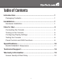
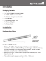
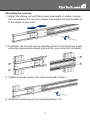
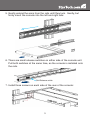
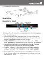
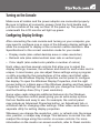
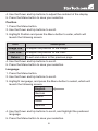
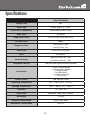
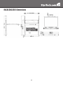
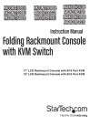
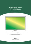
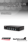
RACKCONS2001
Instruction Manual
Folding Rackmount Console
1U 20.1” Folding LCD
Rackmount Console
- USB and PS/2
FCC Compliance Statement
This equipment has been tested and found to comply with the limits for a Class B digital
device, pursuant to part 15 of the FCC Rules. These limits are designed to provide
reasonable protection against harmful interference in a residential installation. This
equipment generates, uses and can radiate radio frequency energy and, if not installed
and used in accordance with the instructions, may cause harmful interference to radio
communications. However, there is no guarantee that interference will not occur in a
particular installation. If this equipment does cause harmful interference to radio or
television reception, which can be determined by turning the equipment off and on, the
user is encouraged to try to correct the interference by one or more of the following
measures:
• Reorient or relocate the receiving antenna.
• Increase the separation between the equipment and receiver.
• Connect the equipment into an outlet on a circuit different from that to which the receiver
is connected.
• Consult the dealer or an experienced radio/TV technician for help.
Use of Trademarks, Registered Trademarks, and other Protected Names and Symbols
This manual may make reference to trademarks, registered trademarks, and other
protected names and/or symbols of third-party companies not related in any way to
StarTech.com. Where they occur these references are for illustrative purposes only
and do not represent an endorsement of a product or service by StarTech.com, or an
endorsement of the product(s) to which this manual applies by the third-party company
in question. Regardless of any direct acknowledgement elsewhere in the body of
this document, StarTech.com hereby acknowledges that all trademarks, registered
trademarks, service marks, and other protected names and/or symbols contained in this
manual and related documents are the property of their respective holders.
Table of Contents
Introduction...................................................................... 1
Packaging Contents..................................................................... 1
Installation........................................................................ 1
Hardware Installation.................................................................... 1
How to Use....................................................................... 4
Connecting the Console............................................................... 4
Turning on the Console................................................................ 5
Configuring Display Settings........................................................ 5
Testing the Console...................................................................... 6
Panel Controls and OSD Functions.............................................. 6
Specifications................................................................... 10
RACKCONS2001 Dimensions..................................................... 11
Technical Support............................................................ 12
Warranty Information....................................................... 12
Screen Quality & Pixel Policy....................................................... 12
i
Introduction
Packaging Contents
• 1 x 1U LCD Rack Console Drawer
• 1 x VGA + PS/2 console cable
• 1 x 3.5mm mini-jack audio cable
• 1 x USB cable
• 1 x Mounting Rails - Set
• 1 x Power Adapter
• 1 x Power Cord
Installation
Hardware Installation
Screw kit
Side Rails with front and rear brackets (2)
(Used to attach
Rail Mount to
Console body)
Hardware Kit Contents
• Please check that all packaging contents are present before
installation. Make sure that nothing was damaged and/or lost during
shipping process. If you encounter any problem, please contact
StarTech.com (Phone#: 1-800-265-1844).
• Before installation, make sure all peripherals and computer have
been turned off.
• The cabinet depth range must be in 764 ~ 1000 mm.
1
Mounting the console
1.Adjust the sliding rail until the screw underneath is visible. Loosen
(do not release) the two rear screws then adjust the rear bracket to
fit the depth of your rack:
2.Install the rail into the rack by attaching them to the front/rear posts
using the appropriate screws and nuts for your rack (not included):
3.Tighten the rear screws that were loosened in Step 1:
4.Install the remaining rail, by repeating Steps 1-3.
2
5.Gently extend the arms from the rails until they lock. Gently, but
firmly insert the console into the left and right rails:
6.There are small release switches on either side of the console unit.
Pull both switches at the same time, as the console is installed onto
the rails.
Rail-Release switch
7.Install three screws on each side of the rear of the console:
3
8.Installation is now complete.
How to Use
Connecting the Console
3.5mm mini-jack
Power
PS/2
Audio In
connector connector
VGA
connector
USB
connector
USB-PS/2 switch
DVI connector
To connect the LCD console to a computer, perform the following steps:
1.Turn off your computer.
2.Connect the VGA or DVI video cable from the VGA/DVI output on
the computer system to the VGA or DVI port on the rear of the rack
console. Only connect one or the other, not both.
3.Set the USB-PS/2 switch on the console to either USB or PS/2
mode, depending on which you wish to use to connect the computer.
4.Connect either the USB or PS/2 connector on the rear of the rack
console to a USB or PS/2 port on the computer system.
5.For audio, connect a 3.5mm audio cable to the Line In connector
on the console to the Line Out on the computer or external KVM
(available separately, such as StarTech.com ID: SV831DUSBAU).
6.Connect the power adapter and power cord to the power connector
on the console. Connect the remaining end of the power cord to an
available power outlet.
4
Turning on the Console
Make sure all cables and the power adapter are connected properly.
Be sure to tighten all connector screws. Grab the front handle and
pull the console all the way out then lift the panel up. The power LED
underneath the LCD monitor will light up green.
Configuring Display Settings
After connecting the rack console and turning on your computer, you
may need to configure one or more of the following display settings to
allow the computer to display at the console’s native resolution. See
Specifications for the correct resolution mode for your model.
• Display mode (also called desktop area or video resolution)
• Refresh rate (also called vertical scan rate or vertical sync)
• Color depth (also called color palette or number of colors)
Each video card has several controls that allow you to adjust the
display settings, however, the software and driver for each video card is
unique. In most cases, you can adjust these settings using a program
or utility provided by the manufacturer of the video card. Most video
cards use the Windows Display Properties control panel to configure
the display. To open the Windows Display Properties, click the right
mouse button in a blank area of the Windows desktop and then select
Properties. The Settings tab usually lets you change the Color Palette
and the Desktop Area (X by Y pixel resolution).
Some video cards integrate additional features into the Windows
Display Properties control panel giving you an extra setup options
that are flexible and easy to use. For example, the control panel
may include an Advanced Properties button, an Adjustment tab, or
a Refresh tab for changing other settings. Other video cards have a
separate utility for setting display properties.
Whenever you change the resolution, color, or refresh rate, the image
size, position, or shape may change. This behavior is normal.You can
readjust the image using the monitor on-screen controls. For more
information on the monitor on-screen controls, refer to Panel controls
5
and OSD functions. For more information on configuring the display
settings, please refer to the manual that accompanied your video card.
Testing the Console
To test that the console is working properly, perform the following steps:
1.Power up the rack console, and then turn on your computer.
2.Make sure the video image is centered within the screen area. Use
the OSD controls to adjust the image (see Panel controls and OSD
functions) or press the Auto button on the right hand side of the
monitor.
Note: If the unit does not power up when the panel is pulled up, try
pushing the soft power on/off button on the right side of the monitor
panel to power up the unit.
Note:You can adjust the horizontal and vertical position, contrast, and
brightness to better suit your video card and your personal preference.
Before you begin, make sure that power to all of the devices you will
be connecting to the console have been turned off. To prevent damage
to your installation due to ground potential difference, make sure that
all of the devices being installed are properly grounded. Once all
peripherals have been connected, please power them on.
Panel Controls and OSD Functions
The following controls are located on the bottom side of the the console
monitor:
Controls
Descriptions
Soft power on/off. Adjacent LED is lit when on.
Auto
Auto-synchronize and scale down display to any valid factory preset
timings.
Up
Press to scroll to the function you want to adjust.
Down
Press to scroll to the function you want to adjust.
Menu
To access the main menu. This button also acts as the Enter button.
6
Auto tune
Press the “Auto tune” button. The panel will adjust the display size
automatically and also tune the panel to its optimized state.
Brightness
1.Press the Menu button.
2.Use the Down and Up buttons to scroll to Brightness.
3.Press the Menu button to enter.
4.Use the Down and Up buttons to adjust the brightness of the display.
5.Press the Menu button to save your selection.
Contrast
1.Press the Menu button.
2.Use the Down and Up buttons to scroll to Contrast.
3.Press the Menu button to enter.
4.Use the Down and Up buttons to adjust the contrast of the display.
5.Press the Menu button to save your selection.
Color
1.Press the Menu button.
2.Use the Down and Up button to scroll.
3.Highlight Color, and press the Menu button to enter, which will
launch the following screen:
Icon
Description
9300°K
To set CIE coordinates at 9300°K color
7500°K
To set CIE coordinates at 7500°K color
6500°K
To set CIE coordinates at 6500°K color
User
Auto color
Return
To set user defined CIE
To automatically adjust color
To exit and return to the previous page
7
4.Use the Down and Up buttons to adjust the contrast of the display.
5.Press the Menu button to save your selection.
Position
1.Press the Menu button.
2.Use the Down and Up buttons to scroll.
3.Highlight Position and press the Menu button to enter, which will
launch the following screen:
Icon
Description
Image Pos
To adjust the position of the image
OSD Pos
To adjust the position of the OSD
Return
To exit and return to the previous page
4.Use the Down and Up buttons to scroll.
5.Press the Menu button to save your selection.
Language
1.Press the Menu button.
2.Use the Down and Up buttons to scroll.
3.Highlight Language, and press the Menu button to select, which will
launch the following screen:
English
German
French
Italian
Spanish
4.Use the Down and Up buttons to scroll, and highlight the preferred
language.
5.Press the Menu button to save your selection.
8
Recall
1.Press the Menu button.
2.Use the Down and Up buttons to scroll to Recall. Press the Menu
button to enter, where you will be able to select Yes/No using the
Down and Up buttons. Once you have done so, press the Menu
button. Note: selecting Yes will return your settings to the factory
default state. Select No if you do not wish to make this change.
Exit
To exit the menu, scroll to Exit and press the Menu button.
Power Indicator
Light Color
Status
Green
ON
RED
Standby
RED
Suspend
RED
OFF
9
Specifications
RACKCONS2001
Display Size
20.1”
Panel Type
Active Matrix TFT LCD
Resolution Capabilities
1600x1200 @ 60Hz (max.)
Back Light
six lamps
Supported Colors
16.7M Colors (8-bit with FRC)
Contrast Ratio
1000:1
Rising Time: 15ms
Response Time
Decay Time: 7ms
Pixel Pitch
0.255mm x 0.255mm
Sync
45~80KHz
Right-Left view: 85° (Typ)
Viewing Angle
Up-Down view: 85° (Typ)
Keyboard / Mouse
106 key USB keyboard with touchpad
Connectors
1 x DE-15 VGA female
1 x 29-pin DVI-I female
2 x PS/2 female
2 x USB type A
1 x 3.5mm mini-jack
1 x DC power
Power Source
100-240 VAC input
Operating Temperature
0°C ~ 50°C (32°F ~ 122°F)
Storage Temperature
-20°C ~ 60°C (-4°F ~ 140°F)
Humidity
10 ~ 90% RH
Dimension
608.4mm x 448.7mm x 44mm
Net Weight
15.5kg
Chassis Construction
Heavy duty steel
Regulatory Certification
CE/FCC
10
RACKCONS2001 Dimensions
11
Technical Support
StarTech.com’s lifetime technical support is an integral part of our commit-ment to provide
industry-leading solutions. If you ever need help with your product, visit www.startech.com/
support and access our comprehensive selection of online tools, documentation, and downloads.
Warranty Information
This product is backed by a one year warranty.
In addition, StarTech.com warrants its products against defects in materials and workmanship
for the periods noted, following the initial date of purchase. During this period, the products may
be returned for repair, or replacement with equivalent products at our discretion. The warranty
covers parts and labor costs only. StarTech.com does not warrant its products from defects or
damages arising from misuse, abuse, alteration, or normal wear and tear.
Limitation of Liability
In no event shall the liability of StarTech.com Ltd. and StarTech.com USA LLP (or their officers,
directors, employees or agents) for any damages (whether direct or indirect, special, punitive,
incidental, consequential, or otherwise), loss of profits, loss of business, or any pecuniary loss,
arising out of or related to the use of the product exceed the actual price paid for the product.
Some states do not allow the exclusion or limitation of incidental or consequential damages. If
such laws apply, the limitations or exclusions contained in this statement may not apply to you.
Screen Quality & Pixel Policy
During the manufacturing process, certain cosmetic imperfections can occur which do not
constitute defects in the screen requiring an RMA replacement. Defective or “dead” pixels or
sub-pixels are common to all manufacturers of LCD displays. Visual imperfections are caused
by one or more defective pixels or sub-pixels.
A pixel is comprised of one red, one green, and one blue sub-pixel. If a defective whole pixel is
always on, it will appear as a bright spot, typically white, yellow or other bright color, while if it is
always off, it will appear as a dark brown of black spot visible on a bright background. A defective
sub-pixel is less visible than a defective whole pixel as it is smaller, and dependent on the color
of the defective sub-pixel as contrasted to the background color.
A display is not deemed defective if it contains less than and up to:
• 3 bright dots (pixel always on)
• 5 dark dots (pixel always off)
• 5 total bright and dark dots (on and off pixels)
If your display appears to have defective pixels or sub-pixels, or if you should have any questions
relating to this policy, please contact StarTech.com technical support either by phone, online
live chat, or email.
12
StarTech.com has been making “hard-to-find easy” since 1985,
providing high quality solutions to a diverse IT and A/V customer
base that spans many channels, including government, education
and industrial facilities to name just a few. We offer an unmatched
selection of computer parts, cables, A/V products, KVM and Server Management solutions, serving a worldwide market through our
locations in the United States, Canada, the United Kingdom and
Taiwan.
Visit www.startech.com today for complete information about all
our products and to access exclusive interactive tools such as the
Cable Finder, Parts Finder and the KVM Reference Guide.