1
SUPER
®
DOUBLE-SIDED STORAGE
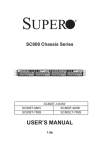
SC417 CHASSIS SERIES
SC417E16-R1400LPB
SC417E26-R1400UB
SC417E16-R1400UB
SC417E26-R1400LPB
USER’S MANUAL
1.0
SC417 Chassis Manual
The information in this User’s Manual has been carefully reviewed and is believed to be accurate.
The vendor assumes no responsibility for any inaccuracies that may be contained in this document,
makes no commitment to update or to keep current the information in this manual, or to notify any
person or organization of the updates. Please Note: For the most up-to-date version of this
manual, please see our web site at www.supermicro.com.
Super Micro Computer, Inc. ("Supermicro") reserves the right to make changes to the product
described in this manual at any time and without notice. This product, including software and
documentation, is the property of Supermicro and/or its licensors, and is supplied only under a
license. Any use or reproduction of this product is not allowed, except as expressly permitted by
the terms of said license.
IN NO EVENT WILL SUPERMICRO BE LIABLE FOR DIRECT, INDIRECT, SPECIAL, INCIDENTAL,
SPECULATIVE OR CONSEQUENTIAL DAMAGES ARISING FROM THE USE OR INABILITY TO
USE THIS PRODUCT OR DOCUMENTATION, EVEN IF ADVISED OF THE POSSIBILITY OF
SUCH DAMAGES. IN PARTICULAR, SUPERMICRO SHALL NOT HAVE LIABILITY FOR ANY
HARDWARE, SOFTWARE, OR DATA STORED OR USED WITH THE PRODUCT, INCLUDING THE
COSTS OF REPAIRING, REPLACING, INTEGRATING, INSTALLING OR RECOVERING SUCH
HARDWARE, SOFTWARE, OR DATA.
Any disputes arising between manufacturer and customer shall be governed by the laws of Santa
Clara County in the State of California, USA. The State of California, County of Santa Clara shall
be the exclusive venue for the resolution of any such disputes. Super Micro's total liability for all
claims will not exceed the price paid for the hardware product.
California Best Management Practices Regulations for Perchlorate Materials: This Perchlorate
warning applies only to products containing CR (Manganese Dioxide) Lithium coin cells. “Perchlorate
Material-special handling may apply. See www.dtsc.ca.gov/hazardouswaste/perchlorate”
WARNING: Handling of lead solder materials used in this
product may expose you to lead, a chemical known to
the State of California to cause birth defects and other
reproductive harm.
Manual Revision 1.0
Release Date: March 14, 2011
Unless you request and receive written permission from Super Micro Computer, Inc., you may not
copy any part of this document.
Information in this document is subject to change without notice. Other products and companies
referred to herein are trademarks or registered trademarks of their respective companies or mark
holders.
Copyright © 2011 by Super Micro Computer, Inc.
All rights reserved.
Printed in the United States of America
ii
Preface
Preface
About This Manual
This manual is written for professional system integrators and PC technicians. It
provides information for the installation and use of the SC417 chassis. Installation
and maintenance should be performed by experienced technicians only.
This manual lists compatible parts available when this document was published. Always refer to the our Web site for updates on supported parts and configurations.
iii
SC417 Chassis Manual
Manual Organization
Chapter 1 Introduction
The first chapter provides a summary of the main components included with the
SC417 chassis and describes the main features of the chassis. This chapter also
includes contact information.
Chapter 2 System Safety
This chapter lists warnings, precautions, and system safety. It is recommended that
you thoroughly familiarize yourself with installing and servicing the chassis and all
safety precautions.
Chapter 3 System Interface
Refer to this chapter for details on the system interface, which includes the functions and information provided by the chassis control panel, as well as other LEDs
located throughout the system.
Chapter 4 Chassis Setup and Maintenance
Refer here for details on this chassis components including the fans, hard drives, air
shrouds, and other components. Follow the procedures given in this chapter when
installing, removing, or reconfiguring components in your chassis.
Chapter 5 Rack Installation
This chapter provides diagrams and information on connectivity configurations for
the SC417 chassis.
Appendix A Hardware
This section provides information on cabling, and other hardware which is compatible with your chassis. For complete information on supported cables and hardware,
refer to the Supermico Web site at www.supermicro.com.
iv
Preface
Appendix B Power Supply Specifications
This chapter lists the specifications of the power supply provided with your chassis. For additional information, refer to the Supermicro website at www.supermicro.
com.
Appendix C SAS2-216EL Backplane Specifications
This section contains detailed specifications on the SAS2-216EL backplane. Additional information can be found on the Supermicro Web site at www.supermicro.
com.
v
SC417 Chassis Manual
Table of Contents
Chapter 1 Introduction
1-1
Overview.......................................................................................................... 1-1
1-2
Shipping List..................................................................................................... 1-1
1-3
Where to get Replacement Components......................................................... 1-2
1-4
Contacting Supermicro..................................................................................... 1-3
1-5
Returning Merchandise for Service................................................................. 1-4
Chapter 2 System Safety
2-1
Overview.......................................................................................................... 2-1
2-2
Warnings and Precautions............................................................................... 2-1
2-3
Preparing for Setup.......................................................................................... 2-1
2-4
Electrical Safety Precautions........................................................................... 2-2
2-5
General Safety Precautions............................................................................. 2-3
2-6
System Safety.................................................................................................. 2-3
Chapter 3 System Interface
3-1
Overview.......................................................................................................... 3-1
3-2
Control Panel Buttons...................................................................................... 3-2
3-3
Control Panel LEDs......................................................................................... 3-2
3-4
Drive Carrier LEDs........................................................................................... 3-4
SAS/SATA Drives............................................................................................. 3-4
SCSI Drives...................................................................................................... 3-4
Chapter 4 Chassis Setup and Maintenance
4-1
Overview.......................................................................................................... 4-1
4-2
Removing the Chassis Cover.......................................................................... 4-2
4-3
Installing Removable Hard Drives................................................................... 4-3
4-4
Installing Optional Fixed Hard Drives.............................................................. 4-6
4-5
Installing the Motherboard............................................................................... 4-8
Permanent and Optional Standoffs.................................................................. 4-8
PCI Slot Setup............................................................................................... 4-10
Expansion Slot Setup in LP (Low Profile) Chassis........................................ 4-10
Expansion Slot Setup in U (Universal Output) Chassis.................................4-11
4-6
Installing the Air Shroud................................................................................. 4-12
4-7
Checking the Server's Air Flow...................................................................... 4-13
4-8
System Fans.................................................................................................. 4-14
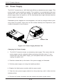
4-9
Power Supply . .............................................................................................. 4-16
vi
Preface
Chapter 5 Rack Installation
5-1
Overview.......................................................................................................... 5-1
5-2
Unpacking the System..................................................................................... 5-1
5-3
Preparing for Setup.......................................................................................... 5-1
Choosing a Setup Location.............................................................................. 5-1
5-4
Warnings and Precautions............................................................................... 5-2
Rack Precautions............................................................................................. 5-2
General Server Precautions............................................................................. 5-2
5-5
Rack Mounting Considerations........................................................................ 5-3
Ambient Operating Temperature...................................................................... 5-3
Reduced Airflow............................................................................................... 5-3
Mechanical Loading......................................................................................... 5-3
Circuit Overloading........................................................................................... 5-3
Reliable Ground............................................................................................... 5-3
5-6
Rack Mounting Instructions.............................................................................. 5-4
Identifying the Sections of the Rack Rails....................................................... 5-4
Locking Tabs.................................................................................................... 5-5
Releasing the Inner Rail.................................................................................. 5-5
Installing The Inner Rails on the Chassis........................................................ 5-6
Installing the Outer Rails on the Rack............................................................. 5-7
Standard Chassis Installation.......................................................................... 5-8
Optional Quick Installation Method.................................................................. 5-9
Adapters for Round and Threaded Hole Racks............................................ 5-10
Appendix A SC417 Cables and Hardware
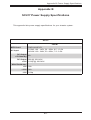
Appendix B SC417 Power Supply Specifications
Appendix C SAS2-216EL1/EL2 Backplane Specifications
vii
SC417 Chassis Manual
Notes
viii
Chapter 1: Introduction
Chapter 1
Introduction
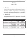
1-1 Overview
The SC417 chassis features extremely high storage density with a maximum of
seventy-two 2.5" hot-swappable drives per enclosure. The chassis also features
high-availability with 1400 Watt Gold Level (1+1) redundant power supplies and
seven 8 cm hot-swappable cooling fans. The SC417 series chassis is ideal for DB/
file servers, data warehouses, media stream servers, video on demand, security
servers and other applications.
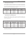
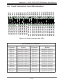
1-2 Shipping List
Please visit the Supermicro Web site for the latest shiping lists and part numbers
for your particular chassis model at http://www.supermicro.com.
SC417 Chassis
Model
CPU
HDD
I/O
Slots
Power
Supply
SC417E16-R1400LPB
DP/UP
72x SAS/SATA
SAS2 support
7x LP
1400W redundant
(Gold Level)
SC417E16-R1400UB
DP/UP
72x SAS/SATA
SAS2 support
4x FF + 3
LP (UIO)
1400W redundant
(Gold Level)
SC417E26-R1400LPB
DP/UP
72x SAS/SATA
SAS2 support
7x LP
1400W redundant
(Gold Level)
SC417E26-R1400UB
DP/UP
72x SAS/SATA
SAS2 support
4x FF + 3
LP (UIO)
1400W redundant
(Gold Level)
1-1
SC417 Chassis Manual
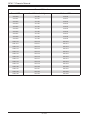
1-3 Where to get Replacement Components
Alhough not frequently, you may need replacement parts for your system. To ensure the highest level of professional service and technical support, we strongly
recommend purchasing exclusively from our Supermicro Authorized Distributors/
System Integrators/Resellers. A list of Supermicro Authorized Distributors/System
Integrators/Resellers can be found at: http://www.supermicro.com. Click the Where
to Buy link.
1-2
Chapter 1: Introduction
1-4 Contacting Supermicro
Headquarters
Address:
Super Micro Computer, Inc.
980 Rock Ave.
San Jose, CA 95131 U.S.A.
Tel:
+1 (408) 503-8000
Fax:
+1 (408) 503-8008
Email:
[email protected] (General Information)
[email protected] (Technical Support)
Web Site:
www.supermicro.com
Europe
Address:
Super Micro Computer B.V.
Het Sterrenbeeld 28, 5215 ML
's-Hertogenbosch, The Netherlands
Tel:
+31 (0) 73-6400390
Fax:
+31 (0) 73-6416525
Email:
[email protected] (General Information)
[email protected] (Technical Support)
[email protected] (Customer Support)
Asia-Pacific
Address:
Super Micro Computer, Inc.
4F, No. 232-1, Liancheng Rd.
Chung-Ho 235, Taipei County
Taiwan, R.O.C.
Tel:
+886-(2) 8226-3990
Fax:
+886-(2) 8226-3991
Web Site:
www.supermicro.com.tw
Technical Support:
Email:
[email protected]
Tel: 886-2-8226-1900
1-3
SC417 Chassis Manual
1-5 Returning Merchandise for Service
A receipt or copy of your invoice marked with the date of purchase is required before any warranty service will be rendered. You can obtain service by calling your
vendor for a Returned Merchandise Authorization (RMA) number. When returning
to the manufacturer, the RMA number should be prominently displayed on the
outside of the shipping carton, and mailed prepaid or hand-carried. Shipping and
handling charges will be applied for all orders that must be mailed when service
is complete.
For faster service, RMA authorizations may be requested online (http://www.
supermicro.com/support/rma/).
Whenever possible, repack the chassis in the original Supermicro carton, using the
original packaging material. If these are no longer available, be sure to pack the
chassis securely, using packaging material to surround the chassis so that it does
not shift within the carton and become damaged during shipping.
This warranty only covers normal consumer use and does not cover damages incurred in shipping or from failure due to the alteration, misuse, abuse or improper
maintenance of products.
During the warranty period, contact your distributor first for any product problems.
1-4
Chapter 2: System Safety
Chapter 2
System Safety
2-1 Overview
This chapter provides a quick setup to get your chassis up and running. Following
the steps in order given should enable you to have your chassis set up and operational within a minimal amount of time. This quick setup assumes that you are an
experienced technician, famailiar with common concepts and terminology.
2-2 Warnings and Precautions
You should inspect the box the chassis was shipped in and note if it was damaged
in any way. If the chassis itself shows damage, file a damage claim with carrier
who delivered your system.
Decide on a suitable location for the rack unit that will hold that chassis. It should
be situated in a clean, dust-free area that is well venilated. Avoid areas where heat,
electrical noise and eletromagnetic fields are generated.
Tthe SC417 chassis includes edundant power supplies which require two grounded
outlets.
2-3 Preparing for Setup
The SC417 chassis includes a set of rail assemblies which includes mounting
brackets and the mounting screws you will need to install the system into a rack.
Read this manual in its entirety before you begin the installation procedure.
2-1
SC417 Chassis Manual
2-4 Electrical Safety Precautions
Basic electrical safety precautions should be followed to protect yourself from harm
and the SC417 from damage:
•Be aware of the locations of the power on/off switch on the chassis as well
as the room’s emergency power-off switch, disconnection switch or electrical
outlet. If an electrical accident occurs, you can then quickly remove power from
the system.
•Do not work alone when working with high-voltage components.
•Power should always be disconnected from the system when removing or install-
ing main system components, such as the serverboard, memory modules (not
necessary for hot-swappable drives). When disconnecting power, you should
first power down the system with the operating system and then unplug the
power cords from all the power supply modules in the system.
•When working around exposed electrical circuits, another person who is fa-
miliar with the power-off controls should be nearby to switch off the power, if
necessary.
•Use only one hand when working with powered-on electrical equipment. This
is to avoid making a complete circuit, which will cause electrical shock. Use
extreme caution when using metal tools, which can easily damage any electrical
components or circuit boards they come into contact with.
•Do not use mats designed to decrease electrostatic discharge as protection from
electrical shock. Instead, use rubber mats that have been specifically designed
as electrical insulators.
•The power supply power cord must include a grounding plug and must be
plugged into a grounded electrical outlet.
•Serverboard battery: CAUTION - There is a danger of explosion if the onboard
battery is installed upside down, which will reverse its polarities This battery
must be replaced only with the same or an equivalent type recommended by
the manufacturer. Dispose of used batteries according to the manufacturer’s
instructions.
2-2
Chapter 2: System Safety
•Please handle used batteries carefully. Do not damage the battery in any way;
a damaged battery may release hazardous materials into the environment. Do
not discard a used battery in the garbage or a public landfill. Please comply
with the regulations set up by your local hazardous waste management agency
to dispose of your used battery properly.
2-5 General Safety Precautions
•Keep the area around the chassis clean and free of clutter.
•Place the chassis top cover and any system components that have been re-
moved away from the system or on a table so that they won’t accidentally be
stepped on.
•While working on the system, do not wear loose clothing such as neckties and
unbuttoned shirt sleeves, which can come into contact with electrical circuits or
be pulled into a cooling fan.
•Remove any jewelry or metal objects from your body, which are excellent metal
conductors that can create short circuits and harm you if they come into contact
with printed circuit boards or areas where power is present.
•After accessing the inside of the system, close the system back up and secure
it to the rack unit with the retention screws after ensuring that all connections
have been made.
2-6 System Safety
Electrostatic discharge (ESD) is generated by two objects with different electrical
charges coming into contact with each other. An electrical discharge is created to
neutralize this difference, which can damage electronic components and printed
circuit boards. The following measures are generally sufficient to neutralize this
difference before contact is made to protect your equipment from ESD:
•Do not use mats designed to decrease electrostatic discharge as protection from
electrical shock. Instead, use rubber mats that have been specifically designed
as electrical insulators.
•Use a grounded wrist strap designed to prevent static discharge.
•Keep all components and printed circuit boards (PCBs) in their antistatic bags
until ready for use.
2-3
SC417 Chassis Manual
•Touch a grounded metal object before removing any board from its antistatic
bag.
•Do not let components or PCBs come into contact with your clothing, which may
retain a charge even if you are wearing a wrist strap.
•Handle a board by its edges only; do not touch its components, peripheral chips,
memory modules or contacts.
•When handling chips or modules, avoid touching their pins.
•Put the serverboard and peripherals back into their antistatic bags when not
in use.
•For grounding purposes, make sure your computer chassis provides excellent
conductivity between the power supply, the case, the mounting fasteners and
the serverboard.
2-4
Chapter 3: System Interface
Chapter 3
System Interface
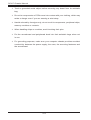
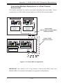
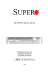
3-1 Overview
There are six LEDs on the front control panel as well as others on the drive carriers to keep you constantly informed of the overall status of the system and over-all
health of specific components. SC417 models have two buttons on the chassis
control panel: A reset button and a power on/off switch. This chapter explains the
meanings of all LED indicators and the appropriate responses you may need to
take.
Figure 3-1: Control Panel
3-1
SC417 Chassis Manual
3-2 Control Panel Buttons
There are two push-buttons located on the left handle of the chassis. From top to
bottom these are a power on/off button and a reset button.
Power: The main power button is used to apply or remove power from the power
supply to the system. Turning off system power with this button removes the main
power but keeps standby power supplied to the system. Therefore, you must unplug system before servicing.
Reset: The reset button is used to reboot the system.
3-3 Control Panel LEDs
The control panel is located on the left handle of the SC417 chassis and has six
LEDs. These LEDs provide you with critical information related to different parts
of the system. This section explains what each LED indicates when illuminated
and any corrective action you may need to take.
Power: Indicates power is being supplied to the system's power supply units. This
LED should normally be illuminated when the system is operating.
HDD: Indicates IDE channel activity. SAS/SATA drive, and/or DVD-ROM drive
activity when flashing.
3-2
Chapter 3: System Interface
1
NIC1: Indicates network activity on GLAN1 when flashing.
2
NIC2: Indicates network activity on GLAN2 when flashing.
Overheat/Fan Fail: When this LED flashes, it indicates a fan failure. When continuously on (not flashing) it indicates an overheat condition, which may be caused
by cables obstructing the airflow in the system or the ambient room temperature
being too warm. Check the routing of the cables and make sure all fans are present and operating normally. You should also check to make sure that the chassis
covers are installed. Finally, verify that the heatsinks are installed properly. This
LED will remain flashing or on as long as the overheat condition exists.
!
Power Failure: When this LED flashes, it indicates a failure in the redundant power
supply.
3-3
SC417 Chassis Manual
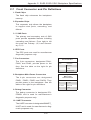
3-4 Drive Carrier LEDs
The SC417 chassis uses SAS or SATA drives.
SAS/SATA Drives
Each SAS/SATA drive carrier has two LEDs.
•Blue:
Solid on = Drive is present and available.
Blinking = Drive is actively being accessed.
Each Serial ATA drive carrier has a blue LED. When illuminated in a solid
on state, this blue LED (on the front of the SAS/SATA drive carrier) indicates
drive activity. A connection to the SAS/SATA backplane enables this LED to
blink on and off when that particular drive is being accessed.
•Red:
Solid on = Drive failure
Blinking = RAID activity
When the red LED is blinking, it indicates that the system is either building,
initializing or rebuilding RAID.
SCSI Drives
This chassis does not support SCSI drives at this time.
3-4
Chapter 4: Chassis Setup and Maintenance
Chapter 4
Chassis Setup and Maintenance
4-1 Overview
This chapter covers the steps required to install components and perform maintenance on the chassis. The only tool you will need to install components and perform
maintenance is a Phillips screwdriver. Print this chapter to use as a reference while
setting up your chassis.
!
Review the warnings and precautions listed in the manual before
setting up or servicing this chassis. These include information in
Chapter 2: System Safety and the warnings/precautions listed in the
setup instructions.
!
Safety Warning: Before performing any chassis setup or maintenance, it is recommended that the chassis be removed from the rack
and placed on a stable bench or table. For instructions on how to
uninstall the chassis from the rack, refer to Chapter 5 Rack Installation in this manual.
4-1
SC417 Chassis Manual
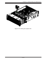
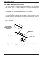
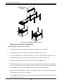
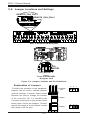
4-2 Removing the Chassis Cover
3
2
12
2
12
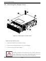
Figure 4-1: Removing the Chassis Cover
Removing the Chassis Cover
1. Unplug the chassis from any power source
2. Remove the screws securing the cover to the chassis.
3. Lift the cover up and off the chassis.
!
Warning: Except for short periods of time, do NOT operate the
server without the cover in place. The chassis cover must be in
place to allow proper airflow and prevent overheating.
4-2
Chapter 4: Chassis Setup and Maintenance
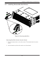
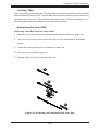
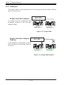
4-3 Installing Removable Hard Drives
2
1
Figure 4-2: Removing Hard Drive
Removing Hard Drive Carriers from the Chassis
1. Press the release button on the drive carrier. This extends the drive carrier
handle.
2. Use the handle to pull the drive carrier out of the chassis.
4-3
SC417 Chassis Manual
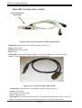
Dummy Drive
Drive Carrier
Figure 4-3: Chassis Drive Carrier
The 2.5" drives are mounted in drive carriers to simplify their installation and removal from the chassis. These carriers also help to promote proper airflow for the
drive bays.
!
Warning: Except for short periods of time (while swapping hard
drives), do not operate the server with the drives removed from
the chassis drive bays.
!
Warning! Enterprise level hard disk drives are recommended for
use in Supermicro chassis and servers. For information on recommended HDDs, visit the Supermicro
Installing a Hard Drive to the Hard Drive Carrier
1. Remove the four screws securing the dummy drive to the drive carrier and
remove the dummy drive.
4-4
Chapter 4: Chassis Setup and Maintenance
SAS/SATA
Hard Drive
Drive Carrier
4
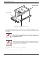
Figure 4-5: Installing the Hard Drive into the Carrier
2. Place the hard drive into the carrier with the printed circuit board side facing
down.
3. Carefully align the mounting holes in the drive carrier with the holes in the
hard drive.
4. Secure the hard drive to the carrier using four screws.
5. Replace the drive tray into the chassis. Make sure to close the drive carrier
handle to lock the drive carrier into place.
5
Figure 4-6: Installing the Hard Drive
4-5
SC417 Chassis Manual
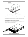
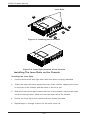
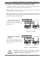
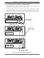
4-4 Installing Optional Fixed Hard Drives
The SC417 chassis includes brackets for installing either one 3.5" fixed hard drive,
or two 2.5" fixed hard drives within the chassis. Each chassis can accomodate up
to two internal drive trays supporting up to two 3.5" hard drives or up to four 2.5"
hard drives. The tray part number is MCP-220-84701-0N.
Installing Fixed HDDs into the SC417 Chassis
1. Disconnect the chassis from any power source.
2. Remove the chassis cover as described in Section 4-2.
3. Remove the screw securing the motherboard node tray to the chassis.
4. Slide back the motherboard node tray to reveal the HDD mounting location on
the floor of the chassis.
Fixed HDD
Mounting
Location
13
14
Figure 4-7: Sliding Back the Motherboard Node Tray
4-6
Chapter 4: Chassis Setup and Maintenance
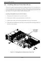
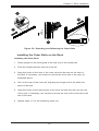
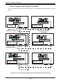
Figure 4-8: Installing Single and Dual Hard Drives and the Bracket
Installing a 3.5" Single Hard Drive into the Bracket
1. Align the four round washers and four screws with the holes in the hard drive
and the holes in the bracket.
2. Secure the hard drive to the bracket using the screws and washers provided.
3. See the instructions below for installing the bracket onto the chassis.
Installing Dual 2.5" Hard Drives into the Bracket
1. Align the eight external tooth washers and eight screws with the holes in the
hard drive and the holes in the bracket.
2. Secure the hard drive to the bracket using the screws and washers provided.
3. See the instructions below for installing the bracket onto the chassis.
Installing the Bracket onto the Chassis
1. Align the holes in the bracket with the chassis standoffs.
2. Secure the bracket using the screws provided.
4-7
Flat head
6-32 x 5 mm
[0.197]
Pan head
6-32 x 5 mm
[0.197]
SC417 Chassis Manual
DVD-ROM, CD-ROM, and FLOPPY DRIVE
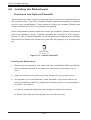
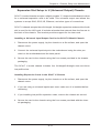
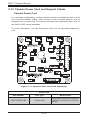
4-5 Installing the Motherboard
Permanent and Optional Standoffs
Flat head
Round head
Pan head
6-32 x 5 mm
M3 x 5 mm
6-32 x 5 mm
[0.197]
[0.197] and
Standoffs prevent short circuits by [0.197]
securing space between
the motherboard
Round hea
M2.6 x 5 m
[0.197]
the chassis surface. The SC417 chassis includes permanent standoffs in locations
RAIL
used by most motherboards. These standoffs accept the rounded Phillips head
screws included in the SC417 accessories packaging.
Some motherboards require additional screws for heatsinks, general components
Flat head
and/or non-standard security. Optional
standoffs are included
to these motherRound head
Flat head
x 4must
mm place the hexagonal
M4 x 4 mm screw through
boards. To use an optional standoff,M4
you
M5 x 12 mm[0.472]
[0.157]
[0.157]
the bottom the chassis and secure the screw with the hexagon nut (roundedWasher
side for M5
M/B STANDOFFS
up).
M/B standoff
6-32 to 6-32
M/B (CPU)
standoff
M5 to 6-32
Figure 4-11: Chassis Standoffs
Thumb screw
6-32 x 5 mm
[0.197]
Installing the Motherboard
1. Review the documentation that came with your motherboard. Become familiar
with component placement, requirements, precautions, and cable connections.
2. Open the chassis cover and remove the chassis from any power source.
3. As required by your motherboard, install standoffs in any areas that do not
have a permanent standoff. Compare the mounting holes in the motherboard
to those in the chassis.
A. Place a hexagonal standoff screw through the bottom the chassis.
B. Secure the screw with the hexagon nut (rounded side up).
4-8
1/U M/B stand
6-32 x 5 mm
[0.197]
Chapter 4: Chassis Setup and Maintenance
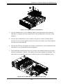
15
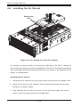
Figure 4-9: Motherboard Installation
4. Lay the motherboard on the chassis aligning the permanent and optional
standoffs. Compare the mounting holes in the motherboard to those in the
chassis.
5. Secure the motherboard to the chassis using the rounded, Phillips head
screws. Do not exceed eight pounds of torque per square inch when tightening down the motherboard.
6. Secure the CPU(s), heatsinks, and other components to the motherboard as
described in the motherboard documentation.
7. Slide back the motherboard tray and connect the cables between the motherboard, backplane, chassis, front panel, and power supply as needed. The
fans may be temporarily removed to allow access to the backplane ports.
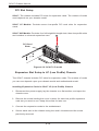
17
Figure 4-10: Slide Back the Motherboard Tray
4-9
SC417 Chassis Manual
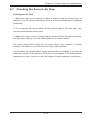
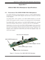
PCI Slot Setup
SC417: The chassis includes PCI slots for expansion cards. The number of cards
used depends on your chassis model.
SC417 LP Models: Provides seven low-profile PCI card slots for expansion
cards.
SC417 UIO Models: Provides four full-height/full-length slots, three low-profile slots
and includes a universal expansion card.
PCI Card
Slots
Figure 4-12: SC417 LP model
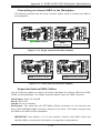
Expansion Slot Setup in LP (Low Profile) Chassis
The SC417 chassis includes PCI slots for expansion cards. The number of cards
you can use depends upon your chassis model and motherboard model.
Installing Expansion Cards in SC417 LP (Low Profile) Chassis
1. Disconnect the power supply, lay the chassis on a flat surface, and open the
chassis cover.
2. Remove the screw holding the cover in place for each low profile expansion
card slot you want to use. Keep this screw for later use.
3. Connect the expansion cards to the motherboard.
4. Secure each card to the chassis using the card's L-bracket and the screw
previously removed.
4-10
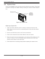
Chapter 4: Chassis Setup and Maintenance
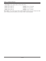
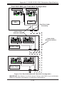
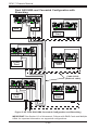
Expansion Slot Setup in U (Universal Output) Chassis
SC417 U model chassis accepts a slightly smaller "L" shaped motherboard to allow
for a universal expansion card to be used. This universal output card allows the
systems t