1
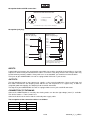
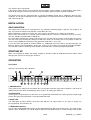
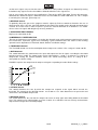
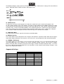
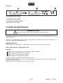
BEDIENUNGSANLEITUNG
USER'S MANUAL
MODE D'EMPLOI
CL-166
COMPRESSOR I LIMITER I GATE
Für weiteren Gebrauch aufbewahren!
Keep this manual for future needs!
Gardez ce mode d’emploi pour des
utilisations ultérieures!
© Copyright
Nachdruck verboten!
Reproduction prohibited!
Réproduction interdit!
MULTI-LANGUAGE-INSTRUCTIONS
Inhaltsverzeichnis/Table of contents/Sommaire
EINFÜHRUNG ................................................................................................................................................... 4
SICHERHEITSHINWEISE................................................................................................................................. 5
BESTIMMUNGSGEMÄSSE VERWENDUNG .................................................................................................. 6
GERÄTEBESCHREIBUNG............................................................................................................................... 7
INSTALLATION ................................................................................................................................................ 8
INBETRIEBNAHME .......................................................................................................................................... 8
BEDIENUNG ..................................................................................................................................................... 9
REINIGUNG UND WARTUNG........................................................................................................................ 12
TECHNISCHE DATEN .................................................................................................................................... 13
INTRODUCTION ............................................................................................................................................. 14
SAFETY INSTRUCTIONS............................................................................................................................... 15
OPERATING DETERMINATIONS.................................................................................................................. 16
DESCRIPTION ................................................................................................................................................ 16
INSTALLATION .............................................................................................................................................. 18
STARTING UP ................................................................................................................................................ 18
OPERATION.................................................................................................................................................... 18
CLEANING AND MAINTENANCE ................................................................................................................. 21
TECHNICAL SPECIFICATIONS..................................................................................................................... 22
INTRODUCTION ............................................................................................................................................. 23
INSTRUCTIONS DE SÉCURITÉ .................................................................................................................... 23
EMPLOI SELON LES PRESCRIPTIONS ....................................................................................................... 25
DESCRIPTION DE L’APPAREIL.................................................................................................................... 25
NETTOYAGE ET MAINTENANCE ................................................................................................................. 29
CARACTÉRISTIQUES TECHNIQUES ........................................................................................................... 30
Das neueste Update dieser Bedienungsanleitung finden Sie im Internet unter:
You can find the latest update of this user manual in the Internet under:
Vous pouvez trouvez la dernière version de ce mode d'emploi dans l'Internet sous:
www.omnitronic.com
3/30
10355585_V_1_0.DOC
BEDIENUNGSANLEITUNG
CL-166
Kompressor I Limiter I Gate
Lesen Sie vor der ersten Inbetriebnahme zur eigenen Sicherheit diese Bedienungsanleitung sorgfältig durch!
Alle Personen, die mit der Aufstellung, Inbetriebnahme, Bedienung, Wartung und Instandhaltung dieses
Gerätes zu tun haben, müssen
- entsprechend qualifiziert sein
- diese Bedienungsanleitung genau beachten
- die Bedienungsanleitung als Teil des Produkts betrachten
- die Bedienungsanleitung während der Lebensdauer des Produkts behalten
- die Bedienungsanleitung an jeden nachfolgenden Besitzer oder Benutzer des Produkts weitergeben
- sich die letzte Version der Anleitung im Internet herunter laden
EINFÜHRUNG
Wir freuen uns, dass Sie sich für einen OMNITRONIC CL-166 entschieden haben. Wenn Sie nachfolgende
Hinweise beachten, sind wir sicher, dass Sie lange Zeit Freude an Ihrem Kauf haben werden.
Nehmen Sie den CL-166 aus der Verpackung.
Features
Stereo Kompressor-Limiter
• 2 Kanäle
• Von Stereo- zu Zwei-Kanal-Monobetrieb schaltbar
• Vergleichsschalter zum schnellen Vergleich von Original und veränderten Strukturen, ohne die
Einstellungen zu verändern
• Pro Kanal Threshold-, Attack-, Release-, Ratio- und Outputregler am Kompressor
• Variables, unabhängiges Gate mit Threshold- und Release-Regler
• Große, übersichtliche LEDs
• Nur 1 HE hoch!
• Schutz vor Übersteuerungen bei Gesangsmikrofon oder dynamischen gespielten Instrumenten
• Ausgleich von Pegelschwankungen von Mikrofonen oder Instrumenten
• Hervorheben eines Signals
• Schutz der Soundanlage vor Überlastung und ggf. Zerstörung
• Zum Überspielen von analog auf digital
4/30
10355585_V_1_0.DOC
SICHERHEITSHINWEISE
ACHTUNG!
Seien Sie besonders vorsichtig beim Umgang mit gefährlicher Netzspannung. Bei dieser Spannung können Sie einen lebensgefährlichen elektrischen Schlag erhalten!
Dieses Gerät hat das Werk in sicherheitstechnisch einwandfreiem Zustand verlassen. Um diesen Zustand zu
erhalten und einen gefahrlosen Betrieb sicherzustellen, muss der Anwender unbedingt die Sicherheitshinweise und die Warnvermerke beachten, die in dieser Gebrauchsanweisung enthalten sind.
Unbedingt lesen:
Bei Schäden, die durch Nichtbeachtung dieser Bedienungsanleitung verursacht werden, erlischt der
Garantieanspruch. Für daraus resultierende Folgeschäden übernimmt der Hersteller keine Haftung.
Bitte überprüfen Sie vor der ersten Inbetriebnahme, ob kein offensichtlicher Transportschaden vorliegt.
Sollten Sie Schäden an der Netzleitung oder am Gehäuse entdecken, nehmen Sie das Gerät nicht in Betrieb
und setzen sich bitte mit Ihrem Fachhändler in Verbindung.
Der Aufbau entspricht der Schutzklasse I. Der Netzstecker darf nur an eine Schutzkontakt-Steckdose
angeschlossen werden, deren Spannung und Frequenz mit dem Typenschild des Gerätes genau
übereinstimmt. Ungeeignete Spannungen und ungeeignete Steckdosen können zur Zerstörung des Gerätes
und zu tödlichen Stromschlägen führen.
Den Netzstecker immer als letztes einstecken. Der Netzstecker muss dabei gewaltfrei eingesetzt werden.
Achten Sie auf einen festen Sitz des Netzsteckers.
Lassen Sie die Netzleitung nicht mit anderen Kabeln in Kontakt kommen! Seien Sie vorsichtig beim Umgang
mit Netzleitungen und -anschlüssen. Fassen Sie diese Teile nie mit feuchten Händen an! Feuchte Hände
können tödliche Stromschläge zu Folge haben.
Netzleitungen nicht verändern, knicken, mechanisch belasten, durch Druck belasten, ziehen, erhitzen und
nicht in die Nähe von Hitze- oder Kältequellen bringen. Bei Missachtung kann es zu Beschädigungen der
Netzleitung, zu Brand oder zu tödlichen Stromschlägen kommen.
Die Kabeleinführung oder die Kupplung am Gerät dürfen nicht durch Zug belastet werden. Es muss stets
eine ausreichende Kabellänge zum Gerät hin vorhanden sein. Andernfalls kann das Kabel beschädigt
werden, was zu tödlichen Stromschlägen führen kann.
Achten Sie darauf, dass die Netzleitung nicht gequetscht oder durch scharfe Kanten beschädigt werden
kann. Überprüfen Sie das Gerät und die Netzleitung in regelmäßigen Abständen auf Beschädigungen.
Werden Verlängerungsleitungen verwendet muss sichergestellt werden, dass der Adernquerschnitt für die
benötigte Stromzufuhr des Gerätes zugelassen ist. Alle Warnhinweise für die Netzleitung gelten auch für
evtl. Verlängerungsleitungen.
Gerät bei Nichtbenutzung und vor jeder Reinigung vom Netz trennen! Fassen Sie dazu den Netzstecker an
der Griffläche an und ziehen Sie niemals an der Netzleitung! Ansonsten kann das Kabel und der Stecker
beschädigt werden was zu tödlichen Stromschlägen führen kann. Sind Stecker oder Geräteschalter, z. B.
durch Einbau nicht erreichbar, so muss netzseitig eine allpolige Abschaltung vorgenommen werden.
Wenn der Netzstecker oder das Gerät staubig ist, dann muss es außer Betrieb genommen werden, der
Stromkreis muss allpolig unterbrochen werden und das Gerät mit einem trockenen Tuch gereinigt werden.
Staub kann die Isolation reduzieren, was zu tödlichen Stromschlägen führen kann. Stärkere Verschmutzungen im und am Gerät dürfen nur von einem Fachmann beseitigt werden.
Es dürfen unter keinen Umständen Flüssigkeiten aller Art in Steckdosen, Steckverbindungen oder in
irgendwelche Geräteöffnungen oder Geräteritzen eindringen. Besteht der Verdacht, dass - auch nur
minimale - Flüssigkeit in das Gerät eingedrungen sein könnte, muss das Gerät sofort allpolig vom Netz
getrennt werden. Dies gilt auch, wenn das Gerät hoher Luftfeuchtigkeit ausgesetzt war. Auch wenn das
Gerät scheinbar noch funktioniert, muss es von einen Fachmann überprüft werden ob durch den
5/30
10355585_V_1_0.DOC
Flüssigkeitseintritt eventuell Isolationen beeinträchtigt wurden. Reduzierte Isolationen können tödliche
Stromschläge hervorrufen.
In das Gerät dürfen keine fremden Gegenstände gelangen. Dies gilt insbesondere für Metallteile. Sollten
auch nur kleinste Metallteile wie Heft- und Büroklammern oder gröbere Metallspäne in das Gerät gelangen,
so ist das Gerät sofort außer Betrieb zu nehmen und allpolig vom Netz zu trennen. Durch Metallteile
hervorgerufene Fehlfunktionen und Kurzschlüsse können tödliche Verletzungen zur Folge haben.
Bevor das Gerät eingeschaltet wird, müssen alle Fader und Lautstärkeregler auf "0" bzw. auf Minimum
gestellt werden.
ACHTUNG: Endstufen immer zuletzt einschalten und zuerst ausschalten!
Kinder und Laien vom Gerät fern halten!
GESUNDHEITSRISIKO!
Beim Betreiben einer Beschallungsanlage lassen sich Lautstärkepegel erzeugen, die zu irreparablen Gehörschäden führen können.
Im Geräteinneren befinden sich keine zu wartenden Teile. Eventuelle Servicearbeiten sind ausschließlich
dem autorisierten Fachhandel vorbehalten!
BESTIMMUNGSGEMÄSSE VERWENDUNG
Bei diesem Gerät handelt es sich um einen professionellen Signalprozessor, mit dem sich ankommende
Audiosignale verändern und komprimieren lassen. Dieses Produkt ist für den Anschluss an 230 V, 50 Hz
Wechselspannung zugelassen und wurde ausschließlich zur Verwendung in Innenräumen konzipiert.
Vermeiden Sie Erschütterungen und jegliche Gewaltanwendung bei der Installierung oder Inbetriebnahme
des Gerätes.
Achten Sie bei der Wahl des Installationsortes darauf, dass das Gerät nicht zu großer Hitze, Feuchtigkeit
und Staub ausgesetzt wird. Vergewissern Sie sich, dass keine Kabel frei herumliegen. Sie gefährden Ihre
eigene und die Sicherheit Dritter!
Betreiben Sie das Gerät nicht in extrem heißen (über 35° C) oder extrem kalten (unter 5° C) Umgebungen.
Halten Sie das Gerät von direkter Sonneneinstrahlung (auch beim Transport in geschlossenen Wägen) und
Heizkörpern fern.
Nehmen Sie das Gerät erst in Betrieb, nachdem Sie sich mit seinen Funktionen vertraut gemacht haben.
Lassen Sie das Gerät nicht von Personen bedienen, die sich nicht mit dem Gerät auskennen. Wenn Geräte
nicht mehr korrekt funktionieren, ist das meist das Ergebnis von unsachgemäßer Bedienung!
Reinigen Sie das Gerät niemals mit Lösungsmitteln oder scharfen Reinigungsmitteln, sondern verwenden
Sie ein weiches und angefeuchtetes Tuch.
Soll das Gerät transportiert werden, verwenden Sie bitte die Originalverpackung, um Transportschäden zu
vermeiden.
Beachten Sie bitte, dass eigenmächtige Veränderungen an dem Gerät aus Sicherheitsgründen verboten
sind.
Der Serienbarcode darf niemals vom Gerät entfernt werden, da ansonsten der Garantieanspruch erlischt.
Wird das Gerät anders verwendet als in dieser Bedienungsanleitung beschrieben, kann dies zu Schäden am
Produkt führen und der Garantieanspruch erlischt. Außerdem ist jede andere Verwendung mit Gefahren, wie
z. B. Kurzschluss, Brand, elektrischem Schlag, etc. verbunden.
6/30
10355585_V_1_0.DOC
GERÄTEBESCHREIBUNG
Der OMNITRONIC Prozessor ist für den professionellen Anwendungsbereich vorgesehen. Die Anschlüsse
befinden sich auf der Rückseite des Gerätes, die Bedienelemente befinden sich auf der Frontseite.
Die Ein- und Ausgänge des OMNITRONIC Prozessors sind mit Klinkenbuchsen, XLR-Einbaukupplungen
und -steckern ausgestattet.
Belegung symmetrische XLR-Leitung:
Symmetrische XLR-Verbindung
2
1
3
1 = Masse / Schirm
2 = Plus-Phase (+)
3 = Minus-Phase (-)
1
Eingang
2
3
Ausgang
Um eine XLR-Verbindung unsymmetrisch an zu schließen,
müssen Pin 1 und 3 gebrückt werden.
Belegung Klinkenstecker:
Unsymmetrischer 6,35 mm
Mono-Klinkenstecker
Symmetrischer 6,35 mm
Stereo-Klinkenstecker
Tip =
Signal (+)
Tip =
Plus-Phase (+)
Ring =
Minus-Phase (-)
Sleeve =
Masse / Schirm
Sleeve =
Masse / Schirm
Tip
Tip
Sleeve
Ring
Sleeve
Zugentlastung
Zugentlastung
Um einen Stereo-Klinkenstecker unsymmetrisch an zu schließen, müssen Ring und
Sleeve gebrückt werden.
EINGÄNGE
Gute Kabelführung verbessert die Klangqualität Ihres PA-Systems enorm. Eingangskabel sollten kurz und
direkt sein, da hohe Frequenzen stark gedämpft werden, wenn die Kabel unnötig lang sind. Außerdem ist die
Gefahr von Brummeinstreuungen und Rauschen bei langen Kabeln erheblich größer. Müssen jedoch lange
Kabelwege zurückgelegt werden, sollten auf jeden Fall symmetrische Kabel verwendet werden.
Die Eingänge Ihres OMNITRONIC Prozessors sind mit XLR- und Klinkenbuchsen ausgestattet.
AUSGÄNGE
Die Ausgänge Ihres OMNITRONIC Prozessors sind mit XLR- und Klinkenbuchsen ausgestattet.
NETZANSCHLUSS
Der OMNITRONIC Prozessor darf erst dann ans Stromnetz angeschlossen werden, wenn sichergestellt ist,
dass die richtige Netzspannung (230 V) vorhanden ist. Ihr Gerät ist mit einer T 0,5 A, 250 V Sicherung
abgesichert.
7/30
10355585_V_1_0.DOC
Schließen Sie das Gerät über die beiliegende Netzanschlussleitung ans Netz an.
Die Belegung der Anschlussleitungen ist wie folgt:
Leitung
Braun
Blau
Gelb/Grün
Pin
Außenleiter
Neutralleiter
Schutzleiter
International
L
N
Der Schutzleiter muss unbedingt angeschlossen werden!
Wenn das Gerät direkt an das örtliche Stromnetz angeschlossen wird, muss eine Trennvorrichtung mit
mindestens 3 mm Kontaktöffnung an jedem Pol in die festverlegte elektrische Installation eingebaut werden.
Das Gerät darf nur an eine Elektroinstallation angeschlossen werden, die den VDE-Bestimmungen
DIN VDE 0100 entspricht. Die Hausinstallation muss mit einem Fehlerstromschutzschalter (RCD) mit 30 mA
Bemessungsdifferenzstrom ausgestattet sein.
INSTALLATION
RACKEINBAU
Dieser Prozessor ist für ein 19" Rack/483 mm vorgesehen. Die Mindesteinbautiefe liegt bei 160 mm. Die
Höhe beträgt 44 mm. Sie können den Prozessor mit vier Schrauben M6 im Rack befestigen.
Beim Rackeinbau ist darauf zu achten, dass die warme Luft aus dem Rack entweichen kann und genügend
Abstand zu anderen Geräten vorhanden ist. Das Rackgehäuse sollte mit einem Lüfter versehen sein.
Seien Sie vorsichtig beim Einbau des Prozessors in ein Rack. Bauen Sie die schwersten Geräte in den
unteren Teil des Racks ein. Die Frontplatte allein reicht allerdings nicht aus, um den Prozessor sicher zu
befestigen. Es muss eine gleichmäßige Befestigung durch Boden- und Seitenschienen gewährleistet sein.
Wenn Racks transportiert oder für mobile Beschallungen verwendet werden, sollte man die Rückbügel der
Geräte noch zusätzlich an den Boden- oder den Seitenschienen des Racks befestigen. So kann sich der
Prozessor beim Transport nicht nach hinten verschieben, da die Frontplatte Beschleunigungskräfte, wie sie
im Roadbetrieb vorkommen, nicht alleine auffangen kann.
INBETRIEBNAHME
Versichern Sie sich, dass der Prozessor vor den Verstärkern angeschaltet wird, um den
Einschalt(bass)schlag zu vermeiden. Dadurch wird verhindert, dass Sie Ihr Publikum verärgern und schützt
Ihre Lautsprecher und Endstufen vor Beschädigung.
8/30
10355585_V_1_0.DOC
BEDIENUNG
Frontseite
Kanal A und Kanal B sind identisch.
1. NETZSCHALTER
Schaltet Ihren Prozessor an und aus. Versichern Sie sich, dass der Prozessor vor den Verstärkern
angeschaltet wird, um den Einschalt(bass)schlag zu vermeiden. Dadurch wird verhindert, dass Sie Ihr
Publikum verärgern und Ihre Lautsprecher und Endstufen werden vor Beschädigung geschützt.
GATE-BEREICH
Aufgabe eines Gates ist es, unerwünschte Hintergrundgeräusche vom Nutzsignal zu trennen und ganz
auszublenden oder wesentlich zu reduzieren, wenn sie unter einen eingestellten Pegel fallen.
2. GATE LED
Diese LED leuchtet, wenn das Gate einstetzt, und kein Signal passiert. Sobald wieder Signale durchgehen,
erlischt die LED.
3. THRESHOLD-Regler
Dieser Regler stellt die Pegelschwelle ein, unterhalb der das Gate einsetzt. Der Einstellbereich liegt
zwischen -45 (OFF) und -10 dB. Über diesem Schwellenwert passiert das Signal das Gate unverändert.
Stellen Sie diesen Regler so ein, dass das Nutzsignal ungehindert passieren kann, Störgeräusche wie
Übersprechen oder Aufrauschen aber ausgeblendet werden. In der OFF-Position sind alle Signale erlaubt.
Durch Drehen im Uhrzeigersinn wird es nur Signalen, die über der Schwelle sind, erlaubt, den
Geräuschsignalpegel zu limitieren.
Wie stellt man einen passenden Gatepegel für die meisten Anwendungen ein? Drehen Sie den GATE
Threshold (Schwelle) auf OFF, schalten Sie alle angeschlossenen Instrumente an, aber ohne ein
Eingangssignal. Erhöhen Sie den Threshold (Schwelle), bis die rote GATE LED zu leuchten beginnt. Dies ist
sehr nützlich, um das Hintergrundrauschen von angeschlossenen Tapes oder Gitarrenverstärkern usw.
auszublenden.
4. RELEASE-Regler
Um das Gate dem Nutzsignal optimal anzupassen, kann mit dem Release-Regler die Geschwindigkeit
eingestellt werden, mit der das Gate schließt, sobald der Signalpegel unter dem Schwellenwert absinkt. Der
Bereich umfasst 0,02 bis 2,0 Sekunden. Nutzen Sie schnellere Werte, um perkussives Klangmaterial mit
wenig bzw. ohne Hallenanteil zu bearbeiten. Wählen Sie langsamere Werte für langsam abklingende oder
stark verhallte Signale.
5. LED GAIN REDUCTION-Anzeige
Zeiget die Absenkung der Lautstärke in dB an.
KOMPRESSOR / LIMITER-BEREICH
Aufgabe des Kompressors ist es, den Dynamikbereich eines Audiosignals einzuschränken und das
Pegelniveau zu kontrollieren. Es wird verhindert, dass das Signal einen eingestellten Pegel (auch Level od.
Schwelle) überschreitet. Der Umfang der resultierenden Dynamik hängt von der Threshold-, Attack-,
Release- und Ratio-Einstellungen ab.
6. THRESHOLD-Regler
Mit dem Threshold-Regler bestimmen Sie den Einsatzpunkt des Kompressors im Bereich von -40 dB bis +20
dB. Der Kompressor wirkt oberhalb der eingestellten Threshold-Schwelle. Signale, die momentan unterhalb
9/30
10355585_V_1_0.DOC
des Thresholds liegen, können ungehindert passieren. Signale, die die eingestellte Threshold-Schwelle
überschreiten, werden vom Kompressor bearbeitet.
7. RATIO-Regler
Dieser Regler bestimmt das Verhältnis von Eingangs- zu Ausgangspegel für alle Signale, die den ThresholdPunkt um mehr als 10 dB überschreiten. Das Verältnis kann stufenlos im Bereich von 1:1 bis oo :1 geregelt
werden. Wird der Regler auf 1:1 eingestellt, gibt es keine Signalkompression. Das Drehen im Uhrzeigersinn
macht die Regelung immer härter, bis der Kompressor bei einer Einstellung von oo :1 schließlich als Limiter
arbeitet und jedes Signal über der eingestellten Schwelle komplett komprimiert.
Die folgende Abbilung erklärt das Verhalten von komprimiertem Signal in Abhängigkeit von verschieden
Ratio-Einstellungen.
8. ATTACK-Regler
Dieser Regler bestimmt die Zeit, die der Kompressor nach Unterschreiten des Threshold-Punktes benötigt
um auf Signale zu reagieren, die den Threshold-Punkt überschreiten. Der Bereich umfasst 0,1 ms bis 100
ms. Nutzen Sie kürzere Attack-Zeiten für einen schnelleren, härteren Einsatz, wie er bei
Perkussionsinstrumenten benötigt wird und langsamere Attack-Zeiten für eine weiche, unhörbare
Kompression.
9. RELEASE-Regler
Dieser Regler bestimmt die Zeit, die der Kompressor nach Unterschreiten des Threshold-Punktes benötigt,
um den ursprünglichen Pegel wieder zu erreichen. Der Bereich umfasst 0,1 sec. bis 2,5 sec. Nutzen Sie
kürzere Werte, um eine effektive Kompression zu erzielen und längere, um das typische „KompressorPumpen“ zu vermeiden.
Die folgende Abbildung stellt dar, wie ATTACK/RELEASE arbeitet. Unterschiedliche Zeiteinstellungen
ergeben unterschiedliche Effekte.
Beispiel: INPUT LEVEL 10 dB bei 4 dB Kompression
10. LEVEL-Regler
Hiermit wird der Ausgangspegel des Kanals bzw. des Geräts eingestellt. Mit diesem Regler können Sie die
Dämpfung des effektiven Signalpegels infolge der Dynamikbearbeitung ausgleichen. Stellen Sie die
gewünschten Kompressor- und Gate-Parameter ein und stellen Sie danach den Level-Regler auf den Wert
10/30
10355585_V_1_0.DOC
ein, den die Gain Reduction-LEDs anzeigen. Wenn diese LEDs z.B. eine durchschnittliche Dämpfung von 10
dB anzeigen, stellen Sie den Level-Regler auf 10 dB, um die 10 dB Dämpfung des Mittelwertpegels
auszugleichen.
11. LED LEVEL-Anzeige
Dient zur Überwachung der Signalpegel, um Verzerrungen durch Übersteuerung zu vermeiden.
12. BYPASS-Schalter
Im BYPASS-Modus wird das Eingangssignal, ohne jegliche Korrektur, direkt auf den Ausgang gelegt und
erlaubt so einen unmittelbaren Vergleich des Sounds mit und ohne Equalizer. Der Bypass-Modus ist auch
bei Stereokopplung (bei gedrückter Stereo/Link-Taste) für beide Kanäle getrennt schaltbar.
13. STEREO / LINK-Schalter
Diese Taste schaltet zwischen Stereo- und Zweikanalbetrieb um. Zum Umschalten auf Stereobetrieb
drücken Sie die Stereo/Link-Taste. Im Stereobetrieb arbeitet Kanal A als Master und Kanal B als Slave. Das
bedeutet, dass sämtliche Bedienelemente und Anzeigen für Kanal B mit Ausnahme der BYPASS-Taste und
der Gain Reduction-Anzeige wirkungslos werden, da die entsprechenden Parameter mit den Reglern für
Kanal A miteingestellt werden.
Bei nichtgedrückter Stereo/Link-Taste arbeitet der CL-166 wie zwei separate Monogeräte, jedes mit eigenen
Bedienelementen.
Empfohlene Kompressor/Limiter Einstellungen
Gesang
Harter Bass
Weicher Bass
E-Gitarre
Akkustik Gitarre
Blasinstrumente
Schlagzeug (Bassdrum, Snare)
Schlagzeug (Becken)
ATTACK
Mittel bis Schnell
Schnell
Mittel bis Langsam
Schnell
Mittel bis Langsam
Schnell
Schnell
Schnell
RELEASE
Mittel bis Langsam
Schnell
Mittel bis Langsam
Langsam
Mittel bis Langsam
Schnell
Schnell
Langsam
RATIO
2:1 bis 4:1
4:1 oder höher
4:1
4:1 oder höher
4:1
5:1 oder höher
4:1
2:1 bis 10:1
Rückseite
1. Eingangs-/Ausgangsbuchsen CH-A
2. Eingangs-/Ausgangsbuchsen CH-B
3. Netzanschluss mit Sicherungshalter
Stecken Sie hier die Netzleitung ein.
11/30
10355585_V_1_0.DOC
REINIGUNG UND WARTUNG
LEBENSGEFAHR!
Vor Wartungsarbeiten unbedingt allpolig vom Netz trennen!
Das Gerät sollte regelmäßig von Verunreinigungen wie Staub usw. gereinigt werden. Verwenden Sie zur
Reinigung ein fusselfreies, angefeuchtetes Tuch. Auf keinen Fall Alkohol oder irgendwelche Lösungsmittel
zur Reinigung verwenden!
Im Geräteinneren befinden sich außer der Sicherung keine zu wartenden Teile. Wartungs- und Servicearbeiten sind ausschließlich dem autorisierten Fachhandel vorbehalten!
Sicherungswechsel
Wenn die Feinsicherung des Gerätes defekt ist, darf diese nur durch eine Sicherung gleichen Typs ersetzt
werden.
Vor dem Sicherungswechsel ist das Gerät allpolig von der Netzspannung zu trennen (Netzstecker
ziehen).
Vorgehensweise:
Schritt 1: Öffnen Sie den Sicherungshalter an der Geräterückseite mit einem passenden
Schraubendreher.
Schritt 2: Entfernen Sie die defekte Sicherung aus dem Sicherungshalter.
Schritt 3: Setzen Sie die neue Sicherung in den Sicherungshalter ein.
Schritt 4: Setzen Sie den Sicherungshalter wieder im Gehäuse ein.
Sollten einmal Ersatzteile benötigt werden, verwenden Sie bitte nur Originalersatzteile.
Wenn die Anschlussleitung dieses Gerätes beschädigt wird, muss sie durch eine besondere Anschlussleitung ersetzt werden, die von Ihrem Fachhändler erhältlich ist.
Sollten Sie noch weitere Fragen haben, steht Ihnen Ihr Fachhändler jederzeit gerne zur Verfügung.
12/30
10355585_V_1_0.DOC
TECHNISCHE DATEN
Systemdaten
Spannungsversorgung:
Gesamtanschlusswert:
Sicherung:
Audio Ein- und Ausgänge:
Eingangsimpedanz:
Ausgangsimpedanz
Frequenzbereich:
Geräuschspannungsabstand:
Crosstalk:
THD:
230 V AC, 50 Hz ~
10 W
T 0,5 A
XLR- und 6,3 mm Klinkenanschluss
10/20 kOhm (unsymm./symm.)
300/150 kOhm (unsymm./symm.)
20 Hz - 20 kHz, ±3 dB
95 dB, ungewichtet
>80 dB
0,05%
Gate-Bereich
Threshold:
Release Zeit:
variabel (45 bis +10 dBu)
variabel (0,1 ms bis 2 sec)
Kompressor-Bereich
Threshold:
Ratio:
Attack-Zeit:
Release-Zeit:
Output:
variabel (-40 bis +22 dBu)
variabel (1:1 bis oo:1)
variabel (0,1 ms bis 100 ms)
variabel (0,05 sec bis 2,5 sec)
variabel (-18 bis +18 dB)
Anzeigen
Gain Reduction:
Output:
VU Meter, 7 LEDs
VU Meter, 7 LEDs
Abmessungen/Gewicht
Maße (BxTxH):
Gewicht:
483 x 147 x 46 mm
2 kg
Bitte beachten Sie: Technische Änderungen ohne vorherige Ankündigung und Irrtum vorbehalten.
06.09.2006 ©
13/30
10355585_V_1_0.DOC
USER MANUAL
CL-166
Compressor I Limiter I Gate
CAUTION!
Keep this device away from rain and moisture!
Unplug mains lead before opening the housing!
For your own safety, please read this user manual carefully before you initial start-up.
Every person involved with the installation, operation and maintenance of this device has to
- be qualified
- follow the instructions of this manual
- consider this manual to be part of the total product
- keep this manual for the entire service life of the product
- pass this manual on to every further owner or user of the product
- download the latest version of the user manual from the Internet
INTRODUCTION
Thank you for having chosen an OMNITRONIC CL-166. If you follow the instructions given in this manual,
we are sure that you will enjoy this device for a long period of time.
Unpack your CL-166.
Features
Indispensable Stereo compressor-limiter
• 2 channels
• Switchable from stereo to mono operation
• Bypass switch allows instant comparison of the original sound with the equalized sound without changing
any settings
• Every channel with threshold, attack, release, ratio, output-control
• Variable independent gate with threshold and release-control
• Large LEDs
• Only 1 U height
• Control of the vocal level of a singer with less microphone technique
• To round excessively filtered sounds
• To even level oscillation of microphones or instruments
• Protects your sound system against override and destruction
• Recording from analogue to digital
14/30
10355585_V_1_0.DOC
SAFETY INSTRUCTIONS
CAUTION!
Be careful with your operations. With a dangerous voltage you can suffer a dangerous
electric shock when touching the wires!
This device has left our premises in absolutely perfect condition. In order to maintain this condition and to
ensure a safe operation, it is absolutely necessary for the user to follow the safety instructions and warning
notes written in this user manual.
Important:
Damages caused by the disregard of this user manual are not subject to warranty. The dealer will
not accept liability for any resulting defects or problems.
If the device has been exposed to drastic temperature fluctuation (e.g. after transportation), do not switch it
on immediately. The arising condensation water might damage your device. Leave the device switched off
until it has reached room temperature.
Please make sure that there are no obvious transport damages. Should you notice any damages on the A/C
connection cable or on the casing, do not take the device into operation and immediately consult your local
dealer.
This device falls under protection-class I. The power plug must only be plugged into a protection class I
outlet. The voltage and frequency must exactly be the same as stated on the device. Wrong voltages or
power outlets can lead to the destruction of the device and to mortal electrical shock.
Always plug in the power plug least. The power plug must always be inserted without force. Make sure that
the plug is tightly connected with the outlet.
Never let the power-cord come into contact with other cables! Handle the power-cord and all connections
with the mains with particular caution! Never touch them with wet hands, as this could lead to mortal
electrical shock.
Never modify, bend, strain mechanically, put pressure on, pull or heat up the power cord. Never operate next
to sources of heat or cold. Disregard can lead to power cord damages, fire or mortal electrical shock.
The cable insert or the female part in the device must never be strained. There must always be sufficient
cable to the device. Otherwise, the cable may be damaged which may lead to mortal damage.
Make sure that the power-cord is never crimped or damaged by sharp edges. Check the device and the
power-cord from time to time.
If extension cords are used, make sure that the core diameter is sufficient for the required power
consumption of the device. All warnings concerning the power cords are also valid for possible extension
cords.
Always disconnect from the mains, when the device is not in use or before cleaning it. Only handle the
power-cord by the plug. Never pull out the plug by tugging the power-cord. Otherwise, the cable or plug can
be damaged leading to mortal electrical shock. If the power plug or the power switch is not accessible, the
device must be disconnected via the mains.
If the power plug or the device is dusty, the device must be taken out of operation, disconnected and then be
cleaned with a dry cloth. Dust can reduce the insulation which may lead to mortal electrical shock. More
severe dirt in and at the device should only be removed by a specialist.
There must never enter any liquid into power outlets, extension cords or any holes in the housing of the
device. If you suppose that also a minimal amount of liquid may have entered the device, it must immediately
be disconnected. This is also valid, if the device was exposed to high humidity. Also if the device is still
15/30
10355585_V_1_0.DOC
running, the device must be checked by a specialist if the liquid has reduced any insulation. Reduced
insulation can cause mortal electrical shock.
There must never be any objects entering into the device. This is especially valid for metal parts. If any metal
parts like staples or coarse metal chips enter into the device, the device must be taken out of operation and
disconnected immediately. Malfunction or short-circuits caused by metal parts may cause mortal injuries.
Before the device is switched on all faders and volume controls have to be set to "0" or "min" position.
CAUTION: Turn the amplifier on last and off first!
Please note that damages caused by manual modifications on the device or unauthorized operation by
unqualified persons are not subject to warranty.
Keep away children and amateurs!
HEALTH HAZARD!
By operating an amplifying system, you can produce excessive sound pressure levels that may
lead to permanent hearing loss.
There are no serviceable parts inside the device. Maintenance and service operations are only to be carried
out by authorized dealers.
OPERATING DETERMINATIONS
This device is a professional compressor for modifying and compressing incoming audio-signals. This
product is allowed to be operated with an alternating current of 230 V, 50 Hz and was designed for indoor
use only.
Do not shake the device. Avoid brute force when installing or operating the device.
When choosing the installation-spot, please make sure that the device is not exposed to extreme heat,
moisture or dust. There should not be any cables lying around. You endanger your own and the safety of
others!
Do not operate the device in extremely hot (more than 30° C) or extremely cold (less than 5° C)
surroundings. Keep away from direct insulation (particularly in cars) and heaters.
Operate the device only after having familiarized with its functions. Do not permit operation by persons not
qualified for operating the device. Most damages are the result of unprofessional operation!
Never use solvents or aggressive detergents in order to clean the device! Rather use a soft and damp cloth.
Please use the original packaging if the device is to be transported.
Please consider that unauthorized modifications on the device are forbidden due to safety reasons!
Never remove the serial barcode from the device as this would make the guarantee void.
If this device will be operated in any way different to the one described in this manual, the product may suffer
damages and the guarantee becomes void. Furthermore, any other operation may lead to dangers like shortcircuit, burns, electric shock, etc.
DESCRIPTION
The OMNITRONIC Compressor CL-166 is designed for professional application. The inputs and outputs are
located on the rear panel, the control elements on the front panel.
16/30
10355585_V_1_0.DOC
Occupation balanced XLR-connection:
Balanced use with XLR connectors
2
1
3
1 = Ground / Shield
2 = Hot (+)
3 = Cold (-)
1
Input
2
3
Output
For unbalanced use pin 1 and pin 3 have to be bridged
Occupation jack plug:
Unbalanced use of
mono 1/4" jack plugs
Balanced use of
stereo 1/4" jack plugs
Tip =
Signal (+)
Tip =
hot (+)
Ring =
cold (-)
Sleeve =
Ground / Shield
Sleeve =
Ground / Shield
Tip
Tip
Sleeve
Ring
Sleeve
Strain relief clamp
Strain relief clamp
For connection of balanced and
unbalanced plugs, ring and sleeve have
to be bridged at the stereo plug.
INPUTS
A good cable run improves the sound quality remarkably. Input cables should be short and direct, since high
frequencies will be mostly be absorbed if the cables are unnecessarily long. Besides that a longer cable may
lead to humming and noise trouble. If long cable runs are unavoidable, you should use balanced cables.
The inputs of your OMNITRONIC CL-166 are equipped with XLR and ¼“ jack-sockets.
OUTPUTS
The high damping factor of your compressor supplies a clear sound reproduction. Unnecessarily long and
thin cables will influence the damping factor and thus the low frequencies in a negative way. In order to
safeguard good sound quality, the damping factor should lie around 50.
The outputs of your OMNITRONIC CL-166 are equipped with 6.3 mm jacks and XLR connectors.
CONNECTION TO THE MAINS
Connect the OMNITRONIC CL-166 only after having made sure that the right voltage (230 V) is available.
This device features a T 0.5 A, 250 V fuse.
Connect the device to the mains with the enclosed power supply cable.
The occupation of the connection-cables is as follows:
Cable
Brown
Blue
Yellow/Green
Pin
Live
Neutral
Earth
International
L
N
17/30
10355585_V_1_0.DOC
The earth has to be connected!
If the device will be directly connected with the local power supply network, a disconnection switch with a
minimum opening of 3 mm at every pole has to be included in the permanent electrical installation.
The device must only be connected with an electric installation carried out in compliance with the IECstandards. The electric installation must be equipped with a Residual Current Device (RCD) with a maximum
fault current of 30 mA.
INSTALLATION
RACK MOUNTING
The compressor is built for 19" racks/483 mm. The minimum mounting depth is 160 mm. The height is 44
mm. You can fix the compressor with four screws M6 in the rack.
When mounting the compressor into a rack, please make sure that there is a proper air circulation.
Please make sure that there is enough space around the device so that the heated air can be passed on.
The rack should be provided with a cooling fan.
Be careful when mounting the compressor into the rack. Put the heaviest devices into the lower part of the
rack. Be aware that fastening the compressor with four screws on the front panel is not enough. In order to
ensure safety, additional fastening by using ground and side bars is necessary.
If racks are to be transported or used for mobile use, additionally fasten the devices by connecting the rear
brackets with the side or ground bars of the rack. In this way, the compressor cannot be pushed backwards.
The front panel alone is not designed to absorb acceleration forces occuring during transportation.
STARTING UP
Make sure to power-up before your power amplifier is turned in order to avoid loud transients which could
damage your speakers or annoy your audience.
OPERATION
Front panel
Channel A and Channel B are identical.
1. POWER Switch
Turns power to the compressor on and off. Be sure to power-up before your power amplifier is turned on to
avoid loud transients which could damage your speakers or annoy your audience.
GATE-SECTION
A noise gate is a signal processor that turns off or significantly accentuates the audio signal passing through
it when the signal level falls below a user adjustable threshold.
2. GATE LED
This LED lights up when GATE is on processing and thus no signal comes in. As soon as singals are
passing through, the LED turns off.
3. THRESHOLD Control
Use the Threshold-Control to determine the threshold point below which expansion occurs. The range of this
control is from -45 dB(OFF) to +10 dB. Signals above this threshold value pass unaltered. Adjust this control
18/30
10355585_V_1_0.DOC
so that music signals can pass but the noise is faded out. In OFF position, all signals are allowed. By turning
it clockwise only signals over the threshold are allowed to limit the noise signal level.
How to set a proper gate level for most applications? Turn off the GATE Threshold. Turn on all instruments
hooked to this unit but no input is allowed. Increase the Threshold, the GATE LED comes on. This is helpful
in removing hiss from tape, guitar amps etc.
4. RELEASE Control
To optimally adapt the gate to the program material, adjust the Release-control to determine the rate at
which the gate closes once the signal falls below the threshold. This control can be adjusted from 0.02 to 2.0
seconds. Use faster release values to process percussive material with little or no ambience. Use slower
release values for signals with long decay or heavy ambience.
5. GAIN REDUCTION LED Meter
Displays the attenuation in dB.
COMPRESSOR / LIMITER SECTION
The task of Compressors and Limiters is to reduce the dynamic range of the program material and to control
the overall level. It prevents signals from exceeding a given threshold level. The extent of the resulting
dynamic level is dependent on Threshold, Attack, Release and Ration settings.
6. THRESHOLD Control
The Threshold control sets the threshold point for the Compressor section. It has a range of –40 to +20 dB.
7. RATIO Control
This control determins the ratio between the input and output level for all signals exceeding the threshold
point by more than 10 dB. The control range can be adjusted form 1:1 to oo :1. A setting of 1:1 leads to no
compression, turning the control clockwise makes the sound increasingly dense. A setting of oo :1
corresponds to a limiter setting.
FIGURE A explains the comparison of compressed signals responding to various Ratio settings.
8. ATTACK Control
This control detemines the rate by which the compressor responds to the signal which exceeds the
threshold. This control can be adjusted from 0.1 ms to 100 ms. Use short Attack times for percussion and
slower times soft inaudible compression.
9. RELEASE Control
This control determines the rate that the compressor returns to unity again after falling below the threshold
level. This control can be adjusted from 0.1 to 2.5 seconds. Use short times for fast recovery and maximum
output and use longer times to avoid pumping.
19/30
10355585_V_1_0.DOC
The following diagram shows how the ATTACK/RELEASE works. Different time settings will create different
effects. Expample: INPUT LEVEL 10 dB at 4 dB compression
10. LEVEL Control
To adjust the channel or overall output level. Adjust this control to vary the amount of fixed gain in the
CL-166‘s output amplifier stage. This control is especially useful to compensate for RMS level decrease wich
results from the unit’s dynamic processing effects. After you adjust the CL-166‘s controls for desired amount
of compression, set the Level-control to add the same amount of gain that is shown on the Gain Reduction
meter. For example, if the average amount of gain reduction shown on the meter is 10 dB, then setting the
Level control to 10 dB will compensate for the 10 dB average level reduction at the output.
11. LED LEVEL Meter
Lets you keep an eye on the signal level in order to avoid distortion.
12. BYPASS Selector
This switch allows instant comparison of the original sound with the equalized sound. Note that the Bypass
mode works independently for each channel, even if the unit is stereo-coupled (via the Stereo/Link button).
13. STEREO / LINK Button
This button toggles the unit between stereo and dual mono operation. Press the Stereo/Link button IN for
stereo operation where CH A becomes the master controller for both channels. All of CH B’s controls,
buttons and LEDs will be disabled (except for CH B’s Bypass button and Gain Reduction LEDs), as CH B is
the „slave“. With the Stereo/Link button OUT, the unit works as two separate mono compressor/gates, each
with its own independent controls.
Suggested Settings
Vocals
Clicky Bass
Mushy Bass
Raging Electric
Guitar
Acoustic Guitar
Brassy Horns
Drums (kick, snare)
Drums (cymbals)
ATTACK
Medium to Fast
Fast
Medium to Slow
Fast
RELEASE
Medium to Slow
Fast
Medium to Slow
Slow
RATIO
2:1 to 4:1
4:1 or higher
4:1
4:1 or higher
(more sustain)
Medium to Slow Medium to Slow 4:1
Fast
Fast
5:1 or higher
Fast
Fast
4:1
Fast
Slow
2:1 to 10:1
20/30
10355585_V_1_0.DOC
Rear panel
1. Input/Output-Sockets CH-A
2. Input/Output-Sockets CH-B
3. AC-Connection with Fuseholder
Used to plug the power-cord in.
CLEANING AND MAINTENANCE
DANGER TO LIFE!
Disconnect from mains before starting maintenance operation!
We recommend a frequent cleaning of the device. Please use a soft lint-free and moistened cloth. Never use
alcohol or solvents!
There are no servicable parts inside the device except for the fuse. Maintenance and service operations are
only to be carried out by authorized dealers.
Replacing the fuse
If the fine-wire fuse of the device fuses, only replace the fuse by a fuse of same type and rating.
Before replacing the fuse, unplug mains lead.
Procedure:
Step 1: Open the fuseholder on the rearpanel with a fitting screwdriver.
Step 2: Remove the old fuse from the fuseholder.
Step 3: Install the new fuse in the fuseholder.
Step 4: Replace the fuseholder in the housing.
Should you need any spare parts, please use genuine parts.
If the power supply cable of this device becomes damaged, it has to be replaced by a special power supply
cable available at your dealer.
Should you have further questions, please contact your dealer.
21/30
10355585_V_1_0.DOC
TECHNICAL SPECIFICATIONS
System specifications:
Power supply:
Power consumption:
Fuse:
Audio inputs/outputs:
Input impendance:
Output impendance:
Frequency response:
S/N ratio:
Crosstalk:
THD:
230 V AC, 50 Hz ~
10 W
T 0.5 A
XLR and 1/4“ jack
10/20 kOhms (unb./bal.)
300/150 kOhms (unb./bal.)
20 Hz - 20 kHz, ±3 dB
95 dB, unweighted
>80 dB
0.05%
Gate section:
Threshold:
Release time :
variable (-45 to +10 dBu)
variable (0.1 ms to 2 s)
Compressor section:
Threshold:
Ratio:
Attack time:
Release time:
Output:
variable (-40 to +22 dBu)
variable (1:1 to 00:1)
variable (0.1 ms to 100 ms)
variable (0.05 sec to 2.5 sec)
variable (-18 to +18 dB)
Display:
Gain Reduction:
Output:
VU Meter, 7 LEDs
VU Meter, 7 LEDs
Dimensions/Weight:
Dimensions (WxDxH):
Weight:
483 x 147 x 46 mm
2 kg
Please note: Every information is subject to change without prior notice. 06.09.2006 ©
22/30
10355585_V_1_0.DOC
MODE D'EMPLOI
CL-166
Compresseur I Limiteur I Gate
ATTENTION!
Protéger de l'humidité.
Débrancher avant d’ouvrier le boîtier!
Pour votre propre sécurité, veuillez lire ce mode d'emploi avec attention avant la première mise en service.
Toute personne ayant à faire avec le montage, la mise en marche, le maniement et l’entretien de cet
appareil doit
- être suffisamment qualifiée
- suivre strictement les instructions de service suivantes
- considérer ce mode d'emploi comme faisant partie de l'appareil
- conserver le mode d'emploi pendant la durée de vie de l'article
- transmettre le mode d'emploi à un éventuel acheteur ou utilisateur de l'appareil
- télécharger la version ultérieure du mode d'emploi d'Internet
INTRODUCTION
Nous vous remercions d'avoir choisi un OMNITRONIC CL-166. Si vous respectez les instructions de service
suivantes, vous allez profiter longtemps de votre achat.
Sortez le CL-166 de son emballage.
INSTRUCTIONS DE SÉCURITÉ
ATTENTION!
Soyez prudent, lors de manipulations électriques avec une tension dangereuse vous
êtes soumis à des risques d'électrocution!
Cet appareil a quitté les ateliers dans un état irréprochable. Pour assurer un bon fonctionnement, sans
danger, l'utilisateur doit suivre les instructions contenues dans ce mode d'emploi.
Attention:
Tout dommage occasionné par la non observation des instructions de montage ou d'utilisation n'est
pas couvert par la garantie.
23/30
10355585_V_1_0.DOC
L'appareil ne doit pas être mis en service lorsqu'il à été transporté d'un endroit froid à un endroit chaud. Il se
forme de la condensation qui pourrait endommager l'appareil. Laissez celui-ci atteindre la température
ambiante avant de le mettre en service.
Avant tout, assurez-vous que l'appareil n'a pas subi de dommages lors de son transport. Si l'appareil ou le
câble d'alimentation est endommagé, ne jamais mettre l'appareil en service. Contactez immédiatement votre
revendeur.
La construction de l'appareil correspond à la classe de protection I. La fiche secteur doit être connectée
uniquement à une prise secteur à contact de protection. La tension et la fréquence doivent correspondre
exactement à la plaque signalétique de l'appareil. Des tensions inappropriées et des prises secteur
inappropriées peuvent mener à la destruction de l'appareil et à des électrocutions mortelles.
Toujours connecter la fiche secteur en dernier. Il faut insérer la fiche secteur de manière non-violente. Faites
attention à une position bien fixée de la fiche secteur.
Ne laissez pas entrer le câble secteur en contact avec d'autres câbles! Soyez prudent lors du travail avec
des câbles secteur et des alimentations secteur. Ne touchez jamais ces parties avec des mains mouillées!
Des mains mouillées peuvent causer des électrocutions mortelles.
Ne pas modifier, plier, charger de manière mécanique, charger de pression, tirer, chauffer et ne pas
positionner des câbles secteur à proximité de sources de chaleur ou de froid. En cas de non-respect des
dommages du câble secteur, des feux ou des électrocutions mortelles peuvent en résulter.
L'insertion de câble ou l'accouplement à l'appareil ne doit pas être chargé par tension. Il faut toujours avoir
une longueur de câble vers l'appareil, manque de quoi le câble peut être endommagé, ce qui peut mener à
des électrocutions mortelles.
Prenez garde de ne pas coincer ou abimer le câble d'alimentation. Contrôler l'appareil et le câble
d'alimentation régulièrement.
En cas d'utilisation de rallonges il faut s´assurer que la section du fil est admissible pour l'alimentation en
courant nécessaire pour l'appareil. Toutes les indications d'avertissement pour le câble secteur sont aussi
valables pour des rallonges éventuellement utilisées.
Débranchez l'appareil lorsque vous ne l'utilisez pas et avant de le nettoyer. Pour ce faire, utilisez les
surfaces de maintien sur la fiche; ne tirez jamais le câble secteur! Sinon, le câble et la fiche peuvent être
endommagées, ce qui peut mener à des électrocutions mortelles. Si la fiche ou l'interrupteur de l'appareil ne
sont pas accessibles, par exemple parce qu'ils sont enfermés par d'autres pièces, il faut procéder à une
disjonction de tous les pôles du côté secteur.
Si la fiche secteur ou l'appareil sont couverts de poussière, il faut le mettre hors service, il faut interrompre le
circuit sur tous les pôles, et nettoyer l'appareil avec un chiffon sec. La poussière peut réduire l'isolation, ce
qui peut mener à des électrocutions mortelles. Des encrassements plus importants dans l'appareil et sur
l'extérieur de l'appareil ne doivent être enlevés que par un technicien compétent.
Dans aucun cas des liquides de tout genre doivent pénétrer dans des fiches secteur, des connecteurs ou
dans des ouvertures ou fentes d'appareil. S'il y a un doute sur le fait que même une quantité minimale de
liquide aurait pénétré dans l'appareil, il faut immédiatement séparer l'appareil du secteur avec tous les pôles.
C'est valable aussi, si l'appareil a été exposé à une humidité de l'air élevée. Même si l'appareil apparemment
fonctionne toujours, il doit être examiné par un technicien compétent, si par la pénétration de liquide des
isolations ont été éventuellement endommagées. Des isolations réduites peuvent causer des électrocutions
mortelles.
Des objets étranges ne doivent pas entrer dans l'appareil. C'est valable particulièrement pour des pièces
métalliques. Au cas où mêmes des pièces métalliques les plus petites comme des agrafes et trombones ou
des éclats métalliques devaient entrer dans l'appareil, il faut immédiatement mettre l'appareil hors service et
le séparer du secteur avec tous les pôles (tirer la fiche secteur). Des dysfonctionnements et court-circuits
peuvent causer des blessures mortelles.
24/30
10355585_V_1_0.DOC
Avant la mise en marche de l'appareil, assurez-vous que tous les faders et tous les régulateurs de volumes
soient en position "0" ou au minimum.
ATTENTION: Allumez toujour l'amplificateur en dernier lieu et éteignez le en premier!
Tenir les enfants et les novices éloignées de l'appareil.
ATTENTION: Un volume d'écoute trop élevé peut causer des troubles auditifs!
L'intérieur de l'appareil ne contient pas de parties nécessitant un entretien. L'entretien et les réparations
doivent être effectués par un technicien compétent!
EMPLOI SELON LES PRESCRIPTIONS
Cet appareil est un processeur professionel pour modifier et comprimer des signaux audio. Cet appareil doit
être connecté avec une tension alternative de 230 V, 50 Hz et a été conçu pour un usage dans des locaux
clos.
Eviter les secousses et l'emploi de force lors de l’installation ou l'utilisation de l'appareil.
Quand choisir le place d'installation, évitez toutefois les endroits humides, poussiéreux ou trop chauds.
Assurez-vous que les câbles ne traînent pas au sol. Il en va de votre propre sécurité et de celle d'autrui.
Ne pas utiliser l'appareil lorsque la température ambiante est supérieure à 35° C ou inférieure à 5° C. Ne pas
exposer l'appareil directement aux rayons solaires (lors d'un transport dans un véhicule fermé par exemple).
N'utilisez l'appareil qu'après avoir pris connaissance de ses fonctions et possibilités. Ne laissez pas des
personnes incompétentes utiliser cet appareil. La plupart des pannes survenant sur cet appareil sont dues à
une utilisation inappropriée par des personnes incompétentes.
Ne nettoyez pas l'appareil avec des produits de nettoyages trop puissants ou abrasifs. Utilisez un chiffon
doux, humide.
Si vous deviez transporter l'appareil, utilisez l'emballage d'origine pour éviter tout dommage.
Notez que pour des raisons de sécurité, il est interdit d'entreprendre toutes modifications sur l'appareil.
Il est interdit de retirer le code barre de l'appareil. Ceci annulerait toute garantie.
Si l'appareil est utilisé autrement que décrit dans ce mode d'emploi, ceci peut causer des dommages au
produit et la garantie cesse alors. Par ailleurs, chaque autre utilisation est liée à des dangers, comme par ex.
court circuit, incendie, électrocution, etc.
DESCRIPTION DE L’APPAREIL
Cet processeur est concu pour l'usage professionel. Les connexions se trouvent au dos de l’appareil et les
régulateurs au face.
Les entrées et les sorties équipées avec des douilles de jack 6,3 mm et XLR.
Occupation balanced XLR-connection:
Balanced use with XLR connectors
2
1
3
1 = Ground / Shield
2 = Hot (+)
3 = Cold (-)
1
Input
2
3
Output
For unbalanced use pin 1 and pin 3 have to be bridged
25/30
10355585_V_1_0.DOC
Occupation jack plug:
Unbalanced use of
mono 1/4" jack plugs
Balanced use of
stereo 1/4" jack plugs
Tip =
Signal (+)
Tip =
hot (+)
Ring =
cold (-)
Sleeve =
Ground / Shield
Sleeve =
Ground / Shield
Tip
Tip
Sleeve
Ring
Sleeve
Strain relief clamp
Strain relief clamp
For connection of balanced and
unbalanced plugs, ring and sleeve have
to be bridged at the stereo plug.
Raccords d’entrée
Un bon guidage des câbles ameliore remarquablement la qualité du son de votre système PA. Monter les
câbles d’entrée le plus court et le plus direct possible. Une longueur inutile du cablage affaiblira les hautes
fréquences, le risque de ronflement et de bruit en sera plus grand. Si de longs cablages sont inévitables,
utilisez des câbles symmétriques. Les entrées de votre OMNITRONIC CL-166 sont équipés avec douilles de
jack 6,3 mm et XLR.
Raccords de sortie
Les sorties de votre OMNITRONIC CL-166 sont équipés avec douilles de jack 6,3 mm et XLR.
Connexion au secteur
Brancher le OMNITRONIC CL-166 seulement au réseau après avoir assuré une tension de réseau de 230
V. Votre appareil est protégé par un fusible T 0,5 A, 250 V.
Branchez l’appareil avec la fiche au secteur.
L'occupation des câbles de connection est:
Câble
Brun
Bleu
Jaune/Vert
Pin
Phase
Neutre
Terre
International
L
N
La terre doit être connecteé!
Quand vous connectez l'appareil directement au secteur local, vous deviez installer un interrupteur du
secteur avec une aperture de 3 mm au minimum sur chaque pôle.
Cet appareil doit seulement être connecté avec une installation électrique correspondant aux régulations
IEC. L’installation doit être equippée avec un disjoncteur à courant de défaut (RCD) avec un courant
différentiel résiduel de 30 mA.
26/30
10355585_V_1_0.DOC
Instructions pour l’installation en rack
Cet processeur est concu pour être installé dans un rack 19"/483 mm. Le profondeur minimum pour
l'installation est 160 mm. Fixez l'processeur avec 4 vis M6 au rack.
Lors de l’installation du rack faire attention à ce que l’air chaud puisse s’échapper du rack et qu’il y ait
suffisamment de distance entre les étages de sortie. Le boîtier du rack devrait être équipé d’un ventilateur.
Pour cette raison ils sont munis de ventilateurs qui assurent le refroidissement nécessaire.
Soyez prudent lors de l’installation de l’processeur dans un rack. Intégrer les appareils les plus lourds dans
la partie inférieure du rack. La face avant ne suffit pas elle-même pour fixer un égalisateur. Procéder à une
fixation proportionnée à l'aidedes barres transversales et laterales.
Si des racks sont transportés ou utilisés pour des sonorisations mobiles, les ceintres au revers de l’appareil
devraient être fixés en plus à la base ou aux barres du rack. Ainsi l'processeur ne se deplacera pas en
arrière lors du transport.
MISE EN MARCHE
Mettre l'processeur sous tension en premier de façon à éviter les larsens qui peuvent endommager vos
hauts parleurs.
DESCRIPTION DE L'APPAREIL
Panneau avant
Les canaux A et B sont identiques
1. Interrupteur POWER
Mise sous tension de l'appareil. Mettre l'processeur sous tension en premier de façon à éviter les larsens qui
peuvent endommager vos hauts parleurs.
SECTION DE GATE
Le rôle principal d’un gate est de séparer les bruits non souhaités du signal audio et de les rendre ensuite
inaudibles.
2. Indicateurs LED de GATE
Le LED indique si le signal passe ou ne passe pas par le noise gate. Si noise gate est activé et le signal ne
passe pas, le LED est allumé. Il s'éteint si tôt qu'un signal passe.
3. Séléction de THRESHOLD
Le bouton Threshold vous permet de décider de la valeur du niveau seuil pour l’entrée en action de
l’expander. Vous pouvez choisir cette valeur de -45 à 10 dB. Non activé, il laisse passer toutes les
fréquences d'un signal. Le noise gate est activé dans le sens des aiguilles d'une montre pour réduire les
fréquences définies.
4. Séléction de RELEASE (RELÂCHE)
Cette commande permet de déterminer le temps de fermeture de la porte une fois que le signal d’entrée
passe en-dessous du seuil. Le valeurs lents sont utilisé pour la réduction des bruits présents derrière le
chant ou les intruments acoustiques. Le valeurs vites permettent d’accentuer la netteté de percussions
(grosse caisse ou caisse claire, par ex.) et d’empêcher les autres instruments de déborder sur les pistes des
percussions.
5. Indicateurs RÉDUCTION de GAIN
Indique la compression en dB.
27/30
10355585_V_1_0.DOC
SECTION DE COMPRESSEUR / LIMITEUR
Le rôle d’un compresseur est de diminuer le champ dynamique et de contrôler le niveau d’un signal. Ils
évitent qu'un signal ne dépasse un seuil de fréquences données.
6. Séléction de THRESHOLD
La touche Threshold de la section Compresseur permet de déterminer son seuil de mise en marche pour
des valeurs comprises entre -40 et +20 dB. Les signaux sous la valeur seuil passent la section compresseur
sans subir de modification et ceux dépassant cette valeur sant traités par le compresseur.
7. Séléction de RATIO
La touche Ratio détermine le rapport entre les niveaux d’entree et de sorie pour les signaux dépassant la
valeur seuil d’au moins 10 dB. A 1:1 aucun ratio de compression n'est opérationnel. 2:1 donne une
compression de moitié. Infinity compresse le signal complètement.
La figure représente les différents ratios de compression.
8. Séléction de ATTACK
La touche Attack détermine le temps nécessaire au compresseur pour réagir aux signaux qui dépassant a le
niveaux seuil. La plage de réglage de l’attaque s’étend de 0,1 à 100 ms. Utilisez des attaques courtes pur
une mise en action rapide et dure adaptée aux intruments à percussion par exemple, et un temps d’attaque
long pour une compression souple et inaudible.
9. Séléction de RELEASE
La touche Release permet de définir le temps dont le compresseur a besoin pour atteindre à nouveau le
niveau initial àpres que le seuil a été dépassé. La plage de régalage va de 0,05 sec. á 2,5 secondes. Utilisez
des valeurs courtes pur creér une compression effective et des valeurs longues pour obtenir l’effet de
pompage typique de compresseurs.
10. Regulateur du LEVEL (NIVEAU)
Pour régler le niveau de sortie. La commande Level est particulièrement utile pour compenser
l’affaiblissement du signal afficace résultant de effets du traitmant dynamique effectué par le CL-166. Après
avoir sélectionné les niveaux de compression (et de réduciton de bruit) désirés, régler la commande Level
de façon à ajouter le même niveau de gain aue celui affiché par les indicateurs de réduction de gain. Par
example, si le signal subit, en moyenne, une réduction de 10 dB, alors le régalge de la commande Level sur
10 dB permet de compenser ces 10 dB de réduction de gain à la sortie du CL-166.
28/30
10355585_V_1_0.DOC
11. Indicateur LEVEL
Indique le niveau des signaux et permet de visulaliser et d’éviter l’apparition d’éventuelles surcharges.
12. Séléction de EQ BYPASS
Cette fonction permet une comparaison du son travaillé avec l'original. Il est à remarquer que la fonction
Bypass est indépendante pour chaque canal, même lorsque l’appareil est en mode stéréo (par le touche
Stereo/Link).
13. Touche STEREO / LINK
Cette touche permet de choisir entre les modes de fonctionnement stéréo et dual mono. Enfoncer la touche
Stereo/Link pour fonctionner en mode stéréo, à savoir que le CH A devient le circuit maître imposant ses
régalages aux deux canaux. Le CH B devient alors „esclave“ et toutes ses touches, commandes et LEDs
sont désactivées (à l’exeption de sa touche Bypass et de son indicateur Gain Reduction).
Lorsque la touche Stereo/Link est en position relâcée, l’apparail fonctionne comme deux circuits mono
séparés, disposant chacun de ses propres réglages indépendants.
Recommandation
Chant
Basse doux
Basse acerbe
Guitare électrique
Guitare acoustique
Instrument à vent
Percussion (grosse caisse, caisse claire)
Percussion (pad)
ATTACK
Moyen à Vite
Vite
Moyen à Lente
Vite
Moyen à Lente
Vite
Vite
Vite
RELEASE
Moyen à Lente
Vite
Moyen à Lente
Slow
Moyen à Lente
Vite
Vite
Lente
RATIO
2:1 à 4:1
4:1 ou haut
4:1
4:1 ou haut
4:1
5:1 ou haut
4:1
2:1 à 10:1
Dos
1. Douilles d’entrée/de sorties CH-A
2. Douilles d’entrée/de sorties CH-B
3. Connexion de tension avec porte-fusible
Connecter le câble d'alimentation ici.
NETTOYAGE ET MAINTENANCE
DANGER DE MORT!
Toujours débrancher avant de proceder à l'entretien!
L'appareil doit être nettoyé régulièrement de contaminations comme de la poussière etc. Pour le nettoyage,
utilisez un torchon non pelucheux humide. Ne pas utiliser un aucun cas de l’alcool ou des détergents pour le
nettoyage.
29/30
10355585_V_1_0.DOC
L'intérieur de l'appareil ne contient pas de parts nécessitant un entretien sauf le fusible. L'entretien et les
réparations doivent être effectués uniquement par du personnel de service compétent!
Remplacer le fusible
Toujours remplacer un fusible par un autre de modèle identique.
Avant le remplacement du fusible débrancher l'appareil.
Procédure:
Pas 1: Ouvriez le porte-fusible au dos de l'appareil avec un tournevis et le retirer du boîtier.
Pas 2: Retirez le fusible défectueux du porte-fusible.
Pas 3: Installez le nouveau fusible au porte-fusible.
Pas 4: Remettez le porte-fusible dans le boîtier et vissez-le.
Si des pièces de rechange sont nécéssaires, toujours utiliser des pièces d'origine.
Quand le câble secteur de cet appareil est endommagé, il doit être remplacé par un câble secteur spécial
disponible chez votre revendeur.
Pour tout renseignement complémentaire, votre revendeur se tient à votre entière disposition.
CARACTÉRISTIQUES TECHNIQUES
Système
Alimentation:
Puissance de rendement:
Fusible:
Entrées et sorties audio:
Impédance d‘entrée:
Impédance d’sortie:
Bande passante:
Rapport S/N:
Crosstalk:
THD:
230 V AC, 50 Hz ~
10 W
T 0,5 A
XLR et jack 6,3 mm
10/20 kOhm
300/150 kOhm
20 Hz - 20 kHz, ±3 dB
>95 dB
>80 dB
0,05%
Section Gate
Threshold:
Release:
variable (-45 à +10 dBu)
variable (0,1 ms à 2 sec)
Section Compresseur
Threshold:
Ratio:
Attack:
Release:
Output:
variable (-40 à +22 dBu)
variable (1:1 à oo:1)
variable (0,1 ms à 100 ms)
variable (0,05 sec à 2,5 sec)
variable (-18 à +18 dB)
Affichage
Gain Reduction:
Output:
VU-Meter, 7 LEDs
VU-Meter, 7 LEDs
Dimensions/Poids
Dimensions (hxlxp):
Poids:
483 x 147 x 46 mm
2 kg
Attention! Les donnés imprimée dans ce mode d’emploi sont susceptibles d’être modifiées sans préavis.
06.09.2006 ©
30/30
10355585_V_1_0.DOC