1
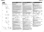
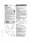
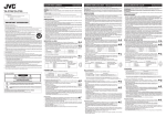
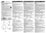
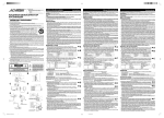
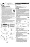
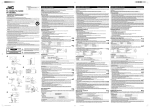
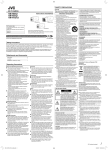
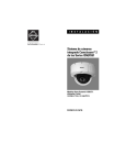
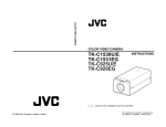
®
For Customer Use:
Enter below the Serial No. which is located on the body.
Retain this information for future reference.
COLOR VIDEO CAMERA
Thank you for purchasing the JVC color video camera.
To obtain the best results from your new camera, read these instructions carefully before use;
retain the manual for future reference.
WARNING:
TO PREVENT FIRE OR SHOCK HAZARD, DO NOT EXPOSE THIS UNIT TO RAIN OR MOISTURE.
Model No.
Serial No.
TK-C750/TK-C751
These instructions are for TK-C750U, TK-C750E and TK-C751EG
Information for USA
This device complies with Part 15 of the FCC Rules.
Changes or modifications not approved by JVC could void the user’s authority to operate the equipment.
IMPORTANT SAFEGUARDS
1.
2.
3.
4.
5.
6.
7.
8.
9.
10.
11.
12.
13.
14.
15.
16.
17.
18.
19.
Read all of these instructions.
Save these instructions for later use.
All warnings on the product and in the operating instructions should be adhered to.
Unplug this appliance system from the wall outlet before cleaning. Do not use liquid cleaners or aerosol cleaners.
Use a damp cloth for cleaning.
Do not use attachments not recommended by the appliance manufacturer as they may cause hazards.
Do not use this appliance near water - for example, near a bathtub, washbowl, kitchen sink, or laundry tub, in a wet
basement, or near a swimming pool, etc.
Do not place this appliance on an unstable cart, stand, or table. The appliance may fall,
PORTABLE CART WARNING
(symbol provided by RETAC)
causing serious injury to a child or adult, and serious damage to the appliance may fall,
causing serious injury to a child or adult, and serious damage to the appliance.
Use only with a cart or stand recommended by the manufacturer, or sold with the appliance.
Wall or shelf mounting should follow the manufacturer’s instructions, and should use a mounting
kit approved by the manufacturer.
An appliance and cart combination should be moved with care. Quick stops, excessive force,
and uneven surfaces may cause the appliance and cart combination to overturn.
Slots and openings in the cabinet and the back or bottom are provided for ventilation, and to
S3125A
insure reliable operation of the appliance and to protect it from overheating, these openings
must not be blocked or covered. The openings should never be blocked by placing the appliance on a bed, sofa,
rug, or other similar surface. This appliance should never be placed near or over a radiator or heat register. This
appliance should not be placed in a built-in installation such as a bookcase unless proper ventilation is provided.
This appliance should be operated only from the type of power source indicated on the marking label. If you are
not sure of the type of power supplied to your home, consult your dealer or local power company. For appliance
designed to operate from battery power, refer to the operating instructions.
This appliance system is equipped with a 3-wire grounding type plug (a plug having a third (grounding) pin). This plug
will only fit into a grounding-type power outlet. This is a safety feature. If you are unable to insert the plug into the
outlet, contact your electrician to replace your obsolete outlet. Do not defeat the safety purpose of the grounding plug.
For added protection for this product during a lightning storm, or when it is left unattended and unused for long
periods of time, unplug it from the wall outlet and disconnect the antenna or cable system. This will prevent
damage to the product due to lightning and power-line surges.
Do not allow anything to rest on the power cord. Do not locate this appliance where the cord will be abused by
persons walking on it.
Follow all warnings and instructions marked on the appliance.
Do not overload wall outlets and extension cords as this can result in fire or electric shock.
Never push objects of any kind into his appliance through cabinet slots as they mat touch dangerous voltage
points or short out parts that could result in a fire or electric shock. Never spill liquid of any kind on the appliance.
Do not attempt to service this appliance yourself as opening or removing covers may expose you to dangerous
voltage or other hazards. Refer all servicing to qualified service personnel.
Unplug his appliance from the wall outlet and refer servicing to qualified service personnel under following conditions:
a. When the power cord or plug is damaged or frayed.
b. If liquid has been spilled into the appliance.
c. If the appliance has been exposed to rain or water.
d. If the appliance does not operate normally by following the operating instructions. Adjust only those controls that
are covered by the operating instructions as improper adjustment of other controls may result in damage and
will often require extensive work by a qualified technician to restore the appliance to normal operation.
e. If the appliance has been dropped or the cabinet has been damaged.
f. When the appliance exhibits a distinct change in performance - this indicates a need for service.
When replacement parts are required, be sure the service technician has used replacement parts specified by the
manufacturer that have the same characteristics as the original part. Unauthorized substitutions may result in fire,
electric shock, or other hazards.
Upon completion of any service or repairs to this appliance, ask the service technician to perform routine safety
checks to determine that the appliance is in safe operating condition.
For USA and CANADA
The lightning flash with arrowhead symbol,
within an equi-lateral triangle, is intended to
alert the user to the presence of uninsulated
“dangerous voltage” within the product’s enclosure that may be of sufficient magnitude
to constitute a risk of electric shock to persons.
CAUTION
RISK OF ELECTRIC SHOCK
DO NOT OPEN
CAUTION: TO REDUCE THE RISK OF ELECTRIC SHOCK.
DO NOT REMOVE COVER (OR BACK).
NO USER SERVICEABLE PARTS INSIDE.
REFER SERVICING TO QUALIFIED SERVICE PERSONNEL.
A
Instructions
The exclamation point within an equilateral triangle is intended to alert the user to the presence of important operating and maintenance
(servicing) instructions in the literature accompanying the appliance.
B
F
(b)
INFORMATION (FOR CANADA) RENSEIGNEMENT (POUR LE CANADA)
This Class [B] digital apparatus complies with Canadian ICES-003.
Cet appareil numérique de la classe [B] est conforme à la norme NMB-003 du Canada.
PRECAUTIONS
• This unit incorporates the AGC (Auto Gain Control) function, which increases the sensitivity
automatically in dark places. It is not a malfunction when the image looks grainy in dark conditions.
• Before mounting the camera, first mount the lens to be used with the camera, and then operate
it in order to check the back focus.
• If a high-intensity object (such as a lamp) is in shot, the image on the screen may have vertical
lines (smear) or blur (blooming) at its periphery (especially in AES mode). This is a characteristic
of the CCD, and is not a defect.
• If an EE lens is used, set the automatic electronic shutter switch (AES) to OFF. If set to ON,
flickering may occur. If a manual iris lens is used, set the AES to ON.
• When used in hot places, vertical lines may appear on the screen of this camera. This is a
characteristic of the CCD and not a failure of the camera.
• The automatic tracking system may not function properly when shooting with non-standard
lighting or lighting with a color temperature which exceeds the capability of the camera.
• If the camera subject is a single solid color (other than white), the auto white circuit will normally
attempt to change this color to white. In the case of this camera, if it cannot make a correct
prediction, the previous white balance setting will be maintained until the subject colors become
more varied.
• This unit assumes that the light source being used is either natural lighting (sunlight) or
incandescent lamps (color temperature 2300 K-10000 K). Under special light sources, such as
sodium lamps, colors may appear different compared to what is visible to the eye.
• Noise may appear in the picture and/or the colors may be incorrect if the camera is used near a
radio or television transmitting antenna, in places where strong electromagnetic waves are
generated by transformers, motors, etc., or near devices emitting radio waves, such as
transceivers or cellular phones.
• This unit accepts only a DC iris lens.
• To save energy, be sure to turn off the system when not in use.
MOUNTING A LENS
1. Before mounting a lens, check whether it is a C-mount or CS-mount lens.
If a C-Mount lens is used, loosen the back-focus locking screw (M 2.6) using a Phillips
head screwdriver, turn the back-focus adjusting ring with your fingers or the screwdriver and change the mounting method.
2. Dimension (b) of the lens shown in the illustration must be as shown in the table
below. If (b) exceeds the value in the table, it may damage the inside of the camera
or correct mounting may be impossible; never use such lenses. Do not attach a Cmount lens when using the CS-mount.
Lens
C mount lens
CS mount lens
Flange back (c)
17.526 mm
12.5 mm
3. Mount the DC IRIS lens on the camera by turning the lens clockwise. Adjust its
position.
4. If the lens has an auto-iris mechanism, connect the lens cable after checking the pin
assignment.
Lens
∆B
1 3
DC IRIS
(does not contain EE amplifier)
1
Brake –
2
Brake +
3
Drive +
Voltage: 0.45 V – 4.05 V
4
Drive –
Current: max. 26 mA
*4 pin plug, service part number: SCV2859-001
For details, please consult your JVC dealer.
[
∆C
]
2 4
(c)
C
D
2. Connect to a video monitor, etc. (75 Ω)
3. When mounting the camera on a fixer, pan/tilt, etc., use the camera mounting screw
hole (d) located on the camera-mounting bracket.
CAUTION: Use a screw shorter in length than 7mm from the camera-mounting
face.
Furthermore, make use of the rotation prevention holes (e) to prevent the camera
from falling and be sure to mount the camera securely.
Special precautions must be taken when mounting the camera on a wall or a ceiling.
JVC is not liable for any damage caused by incorrect installation.
4. Installation of camera
• With the mounting plate on the underside
This camera is originally designed to be mounted from underneath, as shown q.
The hole is standard photographic pan-head screw size (1/4-20 UNC, as is found
in a typical camera fixing point or pan & tilt head.
• With the mounting plate relocated to the topside
Remove the CAMERA MOUNTING BRACKET (f) from the underside of the camera
by removing the two fixing screws as shown w. Attach the CAMERA MOUNTING
BRACKET (f) to the top, then mount the camera on the Fixing Unit as shown e.
Make sure that two original screws are used when mounting the CAMERA
MOUNTING BRACKET (f). Be sure to use a 6 mm long locking screw for the cameramounting bracket.
These instructions assume the camera will only be mounted indoors.
IRIS
L
H
LEVEL
COLOR VIDEO CAMERA
(e)
F
w
q
IRIS
L
H
LEVEL
COLOR VIDEO CAMERA
4mm
(f)
MAX.
7mm
TK-C750
e
Fall Prevention
6mm
IRIS
L
H
OFF
OFF
ATW
LL
LEVEL
COLOR VIDEO CAMERA
PHASE
E
2mm
ON-AES
ON-BLC
AWB
INT
SET
RESET
POWER
T
VIDEO OU
TK-C751
RUCTION
SEE INST MANUAL
• Exercise maximum caution when installing the unit to a wall or ceiling. If in any doubt
ask a professional to do the job, because if the unit were subsequently to fall, it could
result in personal injuries or accidents.
• When installing the unit on a fixer, turn table, etc., be sure to install it firmly and to
use one of the rotation-preventing holes (e) provided.
• As a failsafe against falling, attach the unit by chain, wire cable or other safety restraint to
an appropriate anchor point. Attach the fall prevention wire using the black screw on the
upper surface (TK-C751 : on the rear panel) of the camera as shown in figure F. When
changing the side at which CAMERA MOUNTING BRACKET is installed, be sure to
change the attachment side of the fall prevention wire also to the appropriate side.
• Specified screw (TK-C750 : M2.6 × 4 mm, TK-C751 : M3 × 6 mm )
Never use any screw longer than the specified length as the inside can be damaged.
• Esta unidad incorpora la funcion AGC (control automatico de ganancia), con la que la sensibilidad
aumenta automaticamente en los lugares oscuros. Cuando la imagen aparezca granulada,
esto no significará mal funcionamiento.
• Antes de montar la videocámara, monte primero el objetivo que va a utilizar con ella, y luego
utilícelo para comprobar el enfoque posterior.
• Cuando videofilme un motivo de gran intensidad (como una lámpara), la imagen de la pantalla
puede tener líneas verticales (borrosidad) o desenfoque (hiperluminosidad del punto explorador)
en su periferia (especialmente en el modo de obturador electrónico automático (AES). Ésta es
una característica del dispositivo de transferencia de carga (CCD), y no significa defecto alguno.
• Si utiliza un objetivo EE, ponga el interruptor del obturador electrónico automático (AES) en
OFF. Si lo pusiese en ON podría producirse parpadeo. Si utiliza un objetivo de iris manual,
ponga AES en ON.
• Cuando utilice la videocámara en lugares cálidos, es posible que aparezcan rayas verticales en
la pantalla de la misma. Esta es una característica del dispositivo de transferencia de carga
(CCD), y no significa defecto alguno.
• El sistema de seguimiento automático puede no funcionar adecuadamente cuando videofilme
en condiciones de iluminación no estándar, o con iluminación con una temperatura de color que
sobrepase la capacidad de la videocámara.
• Si somete la videocámara a un solo color (que no sea el blanco), el circuito de equilibrio
automático del blanco intentará normalmente cambiar este color al blanco. En el caso de esta
videocámara, si no puede realizar una predicción correcta, se mantendrá el ajuste del equilibrio
del blanco anterior hasta que los colores se vuelvan más variados.
• Esta unidad asume que la fuente de luz que esta siendo utilizada es luz natural (luz del sol) o
luces incandescentes (temperatura de color de 2300 K-10000 K). Con fuentes de luz especiales
como, por ejemplo lamparas de sodio, los colores pueden aparecer un poco diferentes en
comparacion a como se ven con la vista.
• Se podría producir ruido en la imagen y/o los colores podrían resultar incorrectos si la cámara
se usa cerca de una antena de transmisión de radio o televisión, en lugares en que se generen
fuertes ondas electromagnéticas por transformadores, motores, etc., o cerca de dispositivos
que emitan ondas de radio, tales como transceptores o teléfonos celulares.
• Esta unidad solo acepta un objetivo iris DC.
• Para ahorrar energía, asegúrese de apagar el sistema cuando no esté en uso.
MONTAGE D’UN OBJECTIF
MONTAJE DE UN OBJETIVO
1. Avant de monter l’objectif, vérifier s’il possède une monture C ou une monture CS.
Pour utiliser un objectif à monture C, desserrer la vis de verrouillage de mise au
point arrière (M 2,6) à l’aide d’un tournevis à tête Pillips, puis tourner la bague de
réglage de mise au point arrière avec les doigts ou avec le tournevis, et changer de
méthode de montage.
2. La dimension (b) de l’objectif indiquée sur le schéma doit être comme indiqué dans
le tableau ci-dessous. Si (b) dépasse la valeur du tableau, cela risque d’endommager
l’intérieur de la caméra ou d’empêcher un montage correct ; ne jamais utiliser ce
genre d’objectifs. Ne pas fixer d’objectif à monture C sur une monture CS.
Foyer arrière (c)
17,526 mm
12,5 mm
∆A
∆B
Dimension (b)
10 mm ou moins
5,5 mm ou moins
L’indication F représente le foyer.
3. Monter l'objectif a diaphragme CC sur la camera en tournant l'objectif dans le sens
des aiguilles d'une montre. Ajuster sa position.
4. Si l'objectif possede un diaphragme automatique, raccorder le cable d'objectif apres
avoir verifie l'affectation des broches.
Objectif
Diaphragme CC
(sans amplificateur EE)
No. de broche
1
Frein –
2
Frein +
3
Tournevis +
Tension: 0,45 V – 4,05 V
4
Tournevis –
Amperage: max. 26 mA
]
∆C
1 3
2 4
∆E
Objetivo
Núm. de contacto
1
2
3
4
Iris DC
(No posee amplificador EE)
Freno –
Freno +
Excitación +
Excitación –
Tension: 0,45 V – 4,05 V
[Corriente:
maxima 26 mA ]
∆B
∆C
1 3
2 4
1. Cuando conecte la alimentación de la videocámara, se encenderá el LED POWER.
Tipo de videocámara
Alimentación
TK-C750U
24 V CA ` (clase 2 solamente)
TK-C750E
24 V CA ` (alimentación aislada solamente)
TK-C751EG
220 V a 240 V CA ~ (El cable de alimentación es de 2500 mm de largo.)
EG solamente
Cundo utilice esta videocámara, el tomacorriente deberá estar cerca del equipo
a fin de poder desconectarlo fácilmente.
CA 24 V ` (classe 2 uniquement)
CA 24 V ` (alimentation isolée uniquement)
CA 220 V á 240 V ` (La longueur du câble d’alimentation est de 2500 mm.)
2. Raccorder à un moniteur vidéo, etc. (75 Ω).
3. Pour installer l’appareil sur un module de fixation, un module de mouvement horizontal/vertical, etc., utiliser l’orifice pour vis de montage d’appareil photo (d) situé
sur l’étrier de montage d’appareil photo.
ATTENTION : Utiliser la vis d’une longueur inférieure à 7 mm par rapport à la
surface de montage de l’appareil.
Par ailleurs, utiliser l’orifice de prévention de rotation (e) pour empêcher l’appareil
de tomber et fixer l’appareil solidement.
Prendre des précautions spéciales si la caméra doit être montée sur un mur ou un
plafond. Nous ne saurions être tenus responsables des dommages résultant d’une
installation incorrecte.
4. Installation de la caméra
• Montage sur le fond
La caméra a été originellement conçue pour un montage sur le fond, comme indiqué
sur le schéma q. L’orifice respecte le format de vis photographique à tête à 6 pans
standard (1/4-20 UNC). Exemple : module de fixation ou module de mouvement
horizontal/vertical.
• Montage sur le dessus
Retirer le SOCLE DE MONTAGE DE LA CAMERA (f), sur le fond de la caméra, en enlevant les
deux vis de fixation comme indiqué sur le schéma w. Fixer le SOCLE DE MONTAGE DE LA CAMERA
(f) sur le dessus, puis fixer la caméra sur le module de fixation comme indiqué sur le schéma e.
Bien utiliser les deux vis d’origine pour monter le SOCLE DE MONTAGE DE LA CAMERA (f). Bine
utiliser une vis de fixation de 6 mm de long pour le socle de montage de la caméra.
(La caméra est conçue pour une utilisation à l’intérieur ou dans des conditions similaires.)
∆D
∆E
Prévention des chutes
∆F
3. Monte el objetivo de iris DC en la videocamara girandolo hacia la derecha. Ajuste su
posicion.
4. Si el objetivo tiene un mecanismo de iris automatico, conecte el cable del objetivo
despues de comprobar la asignacion de los contactos.
∆A
CONEXIÓN
EG uniquement
Lors de l’utilisation de la caméra, choisir une prise secteur située prés de l’appareil
de façon à faciliter le débranchement.
∆D
1. Antes de montar un objetivo, compruebe si la montura del mismo es de tipo C o CS.
Si se utiliza un objetivo con montura C, afloje el tornillo de fijación de retrofoco (M
2.6) con un destornillador de cabeza Phillips, y gire el anillo de ajuste de retrofoco
con sus dedos o el destornillador para cambiar el método de montaje.
2. La dimensión (b) del objetivo mostrado en la ilustración deberá ser como se indica en
la tabla siguiente. Si (b) sobrepasa el valor de la tabla, es posible que se dañe el
interior de la videocámara o que el montaje correcto resulte imposible. No utilice nunca
estos objetivos. No instale un objetivo de montura C cuando utilice una montura CS.
Objetivo
Reborde (c)
Dimensión (b)
Objetivo de montura C
17,526 mm
10 mm o menos
Objetivo de montura CS
12,5 mm
5,5 mm o menos
La marca F indica el punto focal.
*Clavija de 4 contactos, numero de pieza: SCV2859-001
Para conocer detalles, consulte a su concesionario JVC.
*Fiche a 4 broches, Numero de piece de service: SCV2859-001
Pour les details, consulter le revendeur JVC.
TK-C750U
TK-C750E
TK-C751EG
EG only
When you use this camera, the socket - outlet must be installed near the equipment to make disconnect on easily.
(d)
PRECAUCIONES
• Cet appareil est pourvu d'une fonction AGC (reglage automatique du gain) qui augmente
automatiquement la sensibilite dans les endroits sombres. Si l’image présente un aspect
granuleux, il ne s’agit pas d’une défaillance.
• Avant de monter la caméra, monter l’objectif à utiliser avec la caméra, puis l’opérer pour vérifier
la mise au point arrière.
• Lors de la prise de vue d’un sujet à forte intensité (par exemple une lampe), l’image de l’écran
risque de présenter des lignes verticales (estompage) ou un flou (flou d’image) sur son pourtour (en
particulier en mode AES). Ceci est typique des capteurs CCD et ne constitue pas une défaillance.
• Si l’on utilise un objectif EE, régler le commutateur d’obturateur électronique automatique (AES)
sur OFF. S’il est réglé sur ON, il risque d’y avoir un phénomène de scintillement. Si l’on utilise un
objectif à diaphragme manuel, régler l’AES sur ON.
• Dans les endroits chauds, des lignes verticales peuvent apparaître sur l’écran de la caméra.
Ceci est typique des capteurs CCD et ne constitue pas une défaillance.
• Le système d’alignement automatique peut ne pas fonctionner correctement lors d’une prise de
vues avec un éclairage non standard ou un éclairage d’une température de couleur dépassant
la capacité de la caméra.
• Si le sujet de la prise de vues est une couleur pleine (autre que le blanc), le circuit automatique
du blanc tentera normalement de transformer cette couleur en blanc. Avec cette caméra, s’il
n’est pas possible d’effectuer un ajustement correct, le réglage précédent de la balance du
blanc sera conservé jusqu’à ce que les couleurs du sujet soient plus diversifiées.
• Cet appareil suppose que la source lumineuse utilisee est un eclairage naturel (lumiere du
soleil) ou des lampes a incandescence (temperature de couleur 2300 K - 10000 K). Sous des
sources lumineuses speciales, telles que lampes au sodium, les couleurs peuvent paraitre
differentes de celles visibles a l'œil.
• Du bruit (c’est-à-dire des parasites) peut apparaitre sur l’image et/ou les couleurs peuvent être
mal reproduites si la caméra est utilisée près d’une antenne d’émission de radio ou de télévision,
à des emplacements où des champs magnétiques puissants sont générés par des
transformateurs, des moteurs, etc., ou près de dispositifs émettant des ondes radio, tels que les
émetteurs-récepteurs ou les téléphones portables.
• Cet appareil accepte uniquement un objectif a iris CC.
• Pour économiser l’énergie, bien mettre le système hors tension lorsqu’on ne s’en sert pas.
1. Quand la caméra est sous tension, le voyant POWER s’allume.
Type de CAMERA
Alimentation
AC 24 V ` (class 2 only)
AC 24 V ` (isolated power only)
AC 220 V to 240 V ` (The power cable is 2500 mm in length.)
Instrucciones
PRÉCAUTIONS
RACCORDEMENT
1. When the camera is powered, the POWER LED lights up.
CAMERA type
power
VIDEOCÁMARA EN COLOR
Muchas gracias por la adquisición de esta videocámara JVC.
Para obtener los mejores resultados de su nueva videocámara, antes de utilizar la videocámara,
lea cuidadosamente este manual de instrucciones, y consérvelo para futuras referencias.
ADVERTENCIA:
PARA EVITAR DESCARGAS ELÉCTRICAS, NO EXPONGA ESTA UNIDAD A LA LLUVIA NI A
LA HUMEDAD.
[
CONNECTION
TK-C750U
TK-C750E
TK-C751EG
Manuel d’instructions
Nous vous remercions d’avoir acheté cette caméra vidéo couleur JVC.
Pour obtenir les meilleurs résultats de votre nouvelle caméra, lisez attentivement ce manuel
d’instructions avant l’utilisation ; puis, conservez le manuel pour toute référence ultérieure.
AVERTISSEMENT :
POUR ÉVITER TOUT RISQUE DE CHOC ÉLECTRIQUE, NE PAS EXPOSER CET APPAREIL À
LA PLUIE NI À L’HUMIDITÉ.
Objectif
Objectif à monture C
Objectif à monture CS
Dimension (b)
10 mm or less
5.5 mm or less
The F mark indicates a focal point.
Pin No.
∆A
CAMÉRA VIDÉO COULEUR
• Faire très attention lors de l’installation de l’appareil sur le mur ou au plafond. Ne pas
effectuer ce travail d’installation soi-même. Confier ce travail à un professionnel, car
la chute de l’appareil pourrait provoquer des blessures et des accidents.
• Si l’on installe l’appareil sur un support, une table rotative, etc., bien le fixer solidement
en utilisant l’un des orifices de prévention de rotation prévus pour l’empêcher de tomber.
• Pour éviter toute chute, raccorder l’appareil à une section suffisamment résistante (dalle de
plafond ou cannelure) en utilisant un fil métallique de prévention des chutes, par exemple une
chaîne métallique. Attacher le fil antichute avec la vis noire sur le dessus de la caméra (TKC751 : panneau arriére) comme indiqué sur la Figure F. En cas de changement du côte de
montage de l'ETRIER DE MONTAGE DE CAMERA, également changer correctement le côte
d'attachement du fil antichute.
Faire également extrêmement attention à la longueur du fil.
• Vis spécifiée (TK-C750 : M2.6 × 4 mm, TK-C751 : M3 × 6 mm )
Ne jamais utiliser de vis d’une longueur supérieure à la longueur spécifiée, car cela risque
∆F
∆D
2. Conecte a un videomonitor, etc. (75 Ω)
3. Cuando instale la videocámara sobre una unidad de fijación o una unidad de
panoramización horizontal/vertical, etc., utilice el orificio roscado (d) de montaje de
la videocámara ubicado en el soporte de montaje de la misma.
PRECAUCION:Utilice un tornillo de un largo inferior a 7 mm desde la superficie
de montaje de la videocámara.
Asimismo, utilice el orificio de prevención contra rotación (e) provisto para evitar las
caídas e instale la videocámara firmemente.
Tome precauciones especiales cuando monte la videocámera en una pared o en el
techo. Nosotros no nos haremos responsables de los daños causados por la
instalación inadecuada.
4. Instalación de la videocámara
• Montaje desde la parte inferior
Esta videocámara ha sido originalmente diseñada para montarse desde la parte
inferior, como se muestra en q. El orificio roscado es de tamaño estándar de
cámaras fotográficas (1/4-20 UNC). Ejemplo de montaje de una unidad de fijación
o una unidad de panoramización horizontal/vertical.
• Montaje desde la parte superior
Quite el SOPORTE DE MONTAJE DE LA VIDEOCÁMARA (f) extrayendo los dos tornillos de
fijación, como se muestra en w. Fije el SOPORTE DE MONTAJE DE LA VIDEOCÁMARA (f)
en la parte superior, y después monte la videocámara en la unidad de fijación como se muestra
en e. Cerciórese de utilizar los dos tornillos originales cuando instale el SOPORTE DE
MONTAJE DE LA VIDEOCÁMARA (f). Asegúrese de usar un tornillo de fijación de 6 mm de
largo para el soporte de montaje de la videocámara.
(Esta videocámara se utiliza en interiores y en condiciones similares.)
∆E
∆F
Prevención de caídas
• Preste suma atención cuando instale la unidad en la pared o el techo. No intente
realizar la instalación por su cuenta. Deje esta tarea en manos de un técnico, ya que
la caída de la unidad puede producir lesiones y accidentes.
• Cuando instale la unidad en un soporte de fijación, mesa giratoria, etc., asegúrese
de instalarla firmemente utilizando el orificio de prevención contra rotación provisto
para evitar las caídas.
• Para evitar caídas, conecte la unidad a una sección suficientemente resistente (bloque o
acanaladura del techo) utilizando un alambre rígido como una cadena metálica o similar. Coloque
el cable para impedir la caida utilizando el tornillo negro de la superficie superior (TK-C751 : en
el panel trasero) de la videocamara como se muestra en la figura F. Cuando cambie el lado en
el que va a instalar el SOPORTE DE MONTAJE DE LA VIDEOCAMARA, asegurese de cambiar
tambien al lado apropiado el cable para impedir la caida.
También preste suma atención al largo del alambre.
• Tornillo especificado (TK-C750 : M2.6 × 4 mm, TK-C751 : M3 × 6 mm )
Para evitar daños interiores, no utilice jamás un tornillo de un largo mayor que el especificado.
LENS ADJUSTMENT
G
Video adjust
Configure the camera according to the Connection instructions above, turn it on, display an image
on the monitor, and check the image. The camera has been factory-set for optimum operation, but
it may need further adjustment according to the prevailing conditions and to the lenses to be used.
If the image does not appear natural, adjust as follows:
• LEVEL adjustment
Monitor screen
Direction of Rotation of LEVEL control
Too bright
Anti-clockwise, towards L (Low)
Too dark
Clockwise, towards H (High)
IRIS
L
∆G
H
LEVEL
COLOR VIDEO CAMERA
LEVEL
• If the sensitivity adjustment LEVEL is turned too far to L, the sensitivity will increase due to the
AGC function of the camera, making the image look grainy.
• In order to adjust the Iris LEVEL of this camera, first, set it to H (iris fully open) and then adjust
the LEVEL slowly to its optimum position.
H
Back focus adjustment
Back focus has been optimally adjusted at the factory for CS-mount lenses, but it may
need re-adjustment if the mount is changed for C-mount lenses. If required, adjust as
follows:
4
5
4
3
2
1
1
2
AC24V
OFF
OFF
ATW
LL
CLASS 2 ONLY(U TYPE)
ISOLATED POWER ONLY
(E TYPE)
PHASE
I
ON-AES
ON-BLC
AWB
INT
SET
6
RESET
5
4
3
2
6
1
Line Lock
SEE INSTRUCTION
MANUAL
VIDEO OUT
TK-C750
TK-C751
∆I
To set the camera in LL mode for synchronization with the power supply frequency, do the following :
1. Turn switch w to “LL”;
2. Press the + or – button q to make the phase variable.
Adjust with the button q so that the vertical phase of the camera matches the vertical phase of
another camera (or system) with a multi-channel oscilloscope.
To reset the setting, press the + and – buttons q simultaneously.
U type
: 60Hz power region only
E/EG type : 50Hz power region only
126
115
U1-32
50
BF LOCK
32.5
50
59
J [: mm]
∆H
• With a zoom lens
If the lens does not track (loses focus) at any point in the zoom range, adjust as follows:
1. Loosen the back focus locking screw by turning it anti-clockwise ( ) with a screwdriver.
2. Point the camera at a comparatively dark scene with thin lines.
3. Set the lens to the maximum telephoto position, and adjust the lens focus.
4. Set the lens to the maximum wide-angle position, and turn the back focus ring to adjust the
focus.
(Repeat steps 2 and 3 two or three times.)
5. Tighten the back focus locking screw by turning it clockwise ( ).
SETTING SWITCH (The illustration shows the factory-set default settings.)
POWER
COLOR VIDEO CAMERA
White Balance
White balance can be adjusted within the scope of 2300 K to 10000 K color temperature. When
switch e is at ATW (Auto-Tracking White Balance), the white balance is automatically adjusted
according to the color temperature of the ambient illumination.
When the white balance is set to AWB (Auto White Balance), press and hold the SET button y for
2 seconds to adjust or readjust the white balance. Once the white balance is adjusted, the setting
will not track changes in the color temperature of the ambient illumination.
30
1/4-20 UNC
MOUNTING HOLE
55
63
35
DIGITAL
42
30
TK-C751
1/4-20 UNC
MOUNTING HOLE
∆H
• Avec un objectif à focale fixe
S’il n’est pas possible de régler la mise au point en tournant la bague de réglage de mise au point,
régler la mise au point arrière comme suit :
1. Desserrer la vis de fixation de mise au point arrière en la tournant dans le sens inverse des
aiguilles d’une montre ( ) à l’aide d’un tournevis.
2. Filmer un motif de près.
3. Tourner la bague de réglage de mise au point sur ∞.
4. Tourner la bague de réglage de mise au point arrière de façon à obtenir la mise au point optimale.
5. Resserrer la vis de fixation de mise au point arrière en la tournant dans le sens des aiguilles
d’une montre ( ).
• Avec un zoom
Si l’image est floue lors d’une prise de vue au zoom (téléobjectif - grand angle), régler la caméra
comme suit :
1. Desserrer la vis de fixation de mise au point arrière en la tournant dans le sens inverse des
aiguilles d’une montre ( ) à l’aide d’un tournevis.
2. Filmer une scène relativement sombre avec des lignes fines.
3. Régler l’objectif sur la position téléobjectif maximale, et régler la mise au point de l’objectif.
4. Régler l’objectif sur la position grand angle maximale, et tourner la bague de mise au point
arrière pour régler la mise au point.
(Recommencer les opérations 2 et 3 deux ou trois fois de suite.)
5. Resserrer la vis de fixation de mise au point arrière en la tournant dans le sens des aiguilles
d’une montre ( ).
RÉGLAGE DES COMMUTATEURS
(L'illustration indique les reglages usine par defaut.)
∆I
Verrouillage sur ligne
Pour régler la caméra en mode LL en vue d’une synchronisation sur l’alimentation électrique,
procéder comme suit :
1. Tourner le commutateur w sur “LL”.
2. Enfoncer le commutateur q sur le côté + ou – et régler la phase variable.
Régler avec la touche q de façon que la phase verticale de la caméra corresponde à la phase
verticale d’une autre caméra (ou d’un système) avec un oscilloscope multi-canaux.
Pour revenir au reglage initial, appuyer simultanement sur les touches + et – q.
Type U
Type E/EG
Turning this switch t “ON” when a lens with a manual iris diaphragm is used enables the automatic adjustment of image brightness. In this case the shutter speed changes according to the
brightness of the subject.
: Régions alimentées sur 60 Hz uniquement
: Régions alimentées sur 50 Hz uniquement
∆J
BLC (Correction de contre-jour)
Le commutateur r améliore une image qui est assombrie sous l’effet d’un contre-jour.
Mettre ce commutateur sur ON pour prendre un sujet à contre-jour.
VICTOR COMPANY OF JAPAN, LIMITED
®
®
LWT0080-001A-H
©2002 VICTOR COMPANY OF JAPAN, LIMITED
is a Registered Trademark owned by VICTOR COMPANY OF JAPAN, LTD.
is a Registrated Trademark in Japan,the U.S.A., the U.K. and many other countries.
Conecte la videocámara de acuerdo con el método de conexión, conecte su alimentación, haga
que se visualice una imagen en el monitor, y compruebéla imagen. La videocámara ha sido
ajustada en fábrica a la mejor posición, pero es posible que haya que ajustarla de acuerdo con las
condiciones del motivo o la combinación de objetivos. Si la imagen aparece innatural, ajuste como
se indica a continuación:
• Ajuste del nivel (LEVEL)
Pantalla del monitor
Demasiado brillante
Demasiado obscura
Dirección de giro de LEVEL
Hacia la izquierda (hacia L)
Hacia la derecha (hacia H)
• Si el ajuste de la sensibilidad LEVEL está demasiado hacia L, la sensibilidad aumentará
debido a la función de control automático de la ganancia (AGC) de la videocámara, y la imagen
aparecerá granulada.
• Para ajustar el control LEVEL del iris de esta videocamara, pongalo primero en la posicion H
(iris completamente abierto) y luego ajustelo lentamente en la posicion optima.
Ajuste del enfoque
El enfoque ha sido ajustado al mejor punto para el objetivo de montura CS, pero es
posible que haya que reajustarlo si cambia a montura C, o si utiliza un objetivo diferente.
Si es necesario, ajústelo de la forma siguiente:
∆H
• Con objetivo de enfoque fijo
Si el enfoque no puede ajustarse correctamente girando el anillo de enfoque del objetivo, ajuste el
enfoque de la forma siguiente.
1. Afloje el tornillo de bloqueo del enfoque girándolo hacia la izquierda ( ) con un destornillador.
2. Videofilme un patrón de cerca.
3. Gire el anillo de enfoque del objetivo a ∞.
4. Gire el anillo de ajuste del enfoque para enfocar el mejor punto.
5. Apriete el tornillo de bloqueo del enfoque girándolo hacia la derecha ( ).
• Con un objetivo zoom
Si la imagen aparece desenfocada cuando utilice el zoom (telefoto/gran angular), ajuste la
videocámara de la forma siguiente:
1. Afloje el tornillo de bloqueo del enfoque girándolo hacia la izquierda ( ) con un destornillador.
2. Videofilme una escena relativamente obscura con líneas finas.
3. Ajuste el objetivo a la posición máxima de telefoto, y después ajuste el enfoque del objetivo.
4. Ajuste el objetivo a la posición máxima de gran angular, y haga retroceder el anillo de enfoque
para ajustar el enfoque.
(Repita los pasos 2 y 3 dos o tres veces.)
5. Apriete el tornillo de bloqueo del enfoque girándolo hacia la derecha ( ).
AJUSTE DEL SELECTOR
∆I
Bloqueo con la línea
Para poner la videocámara en el modo de bloqueo con la línea (LL) para sincronización con la
frecuencia de la fuente de alimentación, realice los pasos siguientes:
1. Ponga el selector w en “LL”.
2. Presione + o – botón q para variar la fase.
Ajuste con el botón q de forma que la fase de la videocámara coincida con la fase vertical de
otra videocámara (o sistema) con un osciloscopio multicanal.
Para reponer la configuracion, pulse simultaneamente los botones + y – q.
Tipo U
: Región de alimentación de 60 Hz solamente
Tipo E/EG : Región de alimentación de 50 Hz solamente
El equilibrio del blanco podrá ajustarse dentro del margen temperatura de color de 2300 K a 10000 K.
Cuando el interruptor e este en ATW (equilibrio del blanco de seguimiento automatico), el equilibrio
del blanco se ajustara automaticamente segun la temperatura del color de la iluminacion.
Cuando el equilibrio del blanco este ajustado en AWB (equilibrio automatico del blanco), pulse y
mantenga pulsado el boton SET y durante 2 segundos para ajustar o reajustar el equilibrio del
blanco. Una vez ajustado el equilibrio del blanco, el ajuste no seguira los cambios de temperatura
del color de la iluminacion ambiental.
Compensación de contraluz (BLC)
El interruptor r mejorará una imagen obscurecida debido a la contraluz.
Para motivos con contraluz, ponga este interruptor en ON.
Obturador electrónico automático (AES)
Enclencher (ON) ce commutateur t lors de l’utilisation d’un objectif à diaphragme manuel pour
obtenir un réglage automatique de la luminosité de l’image. Dans ce cas, la vitesse d’obturation
change en fonction de la luminosité du sujet.
Avec certaines luminosités du sujet, il risque de se produire une instabilité à cause du mécanisme
du circuit AES. Il ne s’agit toutefois pas d’une d’un défaut.
CARACTÉRISTIQUES TECHNIQUES
Dispositif de capture d’image : Capteur d’image CCD 1/3 pouce à transfert interligne
TK-C750U
: 510 (H) × 492 (V)
TK-C750E/TK-C751EG : 500 (H) × 582 (V)
Système de synchronisation : Synchronisation interne
Verrouillage sur ligne (type U: régions à 60 Hz, type E/EG: région
à 50 Hz, uniquement)
Fréquence de balayage
: Type U
: (H) 15,734 kHz, (V) 59,94 Hz
Type E/EG : (H) 15,625 kHz, (V) 50 Hz
Résolution
: 330 lignes TV (H) typ.
VIDEO OUT
: Signal vidéo composite 1 V(c-c), 75 Ω, asymétrique
Rapport S/B vidéo
: 50 dB
Eclairage minimal
: 0,28 lx typ (F1,2, 25%), 0,55 lx typ (F1,2, 50%)
Monture d’objectif
: Monture C/CS
Alimentation
et consommation
: TK-C750U : CA 24 V ` 60 Hz, 3,3 W
TK-C750E : CA 24 V ` 50 Hz/60 Hz, 240 mA
TK-C751EG : CA 220 V - 240 V ` 50 Hz/60 Hz, 42 mA
Température ambiante
: –10 °C à 50 °C (utilisation)
0 °C à 40 °C (recommandée)
Poids
: TK-C750 : 340 g
TK-C751 : 680 g
Accessoire fourni
: CARTE DE GARANTIE (TK-C750U seulement) ... × 1
DIMENSIONS (Unité: mm)
(Conception et spécifications sujettes à modification sans préavis.)
∆J
®
∆G
Ajuste de vídeo
Equilibrio del blanco
AES (Obturateur électronique automatique)
: 1/3-inch interline-transfer CCD
TK-C750U
: 510 (H) × 492 (V)
TK-C750E/TK-C751EG : 500 (H) × 582 (V)
Synchronization method
: Internal
Line lock (U type: 60 Hz, E/EG type: 50 Hz, regions only)
Scanning frequency
: U type
: (H) 15.734 kHz, (V) 59.94 Hz
E/EG type : (H) 15.625 kHz, (V) 50 Hz
Resolution
: 330 TV line (H) Typ.
VIDEO OUT
: Composite video signal 1 V(p-p), 75 Ω, unbalanced
Video S/N ratio
: 50 dB
Minimum required illumination : 0.28 lx typ (F1.2, 25%), 0.55 lx typ (F1.2, 50%)
Lens mount
: C/CS mount
Power supply
: TK-C750U
: AC 24 V ` 60 Hz, 3.3 W
and power consumption
TK-C750E
: AC 24 V ` 50 Hz/60 Hz, 240 mA
TK-C751EG : AC 220 V - 240 V ` 50 Hz/60 Hz, 42 mA
Ambient temperature
: –10 ˚C to 50 ˚C (operation)
0 ˚C to 40 ˚C (recommended)
Mass
: TK-C750 : 340 g
TK-C751 : 680 g
Provided accessory
: WARRANTY CARD (TK-C750U only) ... ×1
DIMENSIONS (Unit: mm)
(Design and specifications are subject to change without notice.)
AJUSTE DEL OBJETIVO
(La ilustracion muestra la configuracion predeterminada en la fabrica.)
AES (Automatic Electronic Shutter)
Image pickup device
125
115
La mise au point arrière a été réglée sur le point optimal pour un objectif à monture CS,
mais il faudra peut-être l’ajuster si l’on utilise une monture C ou un autre objectif. Si
nécessaire, effectuer le réglage comme suit :
La balance des blancs se règle dans la plage d’une température de couleur comprise entre 2300 K
et 10000 K. Quand le commutateur e est regle sur ATW (balance des blancs a suivi automatique),
la balance des blancs est automatiquement ajustee a la temperature de couleur de l'eclairage.
Quand la balance des blancs est reglee sur AWB (balance automatique des blancs), maintenir la
touche SET y pressee 2 secondes pour ajuster ou reajuster la balance des blancs. Une fois la
balance des blancs ajustee, le suivi des changements de temperature de couleur de l'eclairage
ambiant ne sera pas repercute sur le reglage.
The switch r helps to rectify the situation where a subject appears dark because of backlighting.
Set this switch to ON for strongly backlit subjects.
SPECIFICATIONS
U1-32
• Si la commande de sensibilité LEVEL est tournée trop loin vers L, la sensibilité augmentera
sous l’effet de la fonction AGC de la caméra et l’image semblera granuleuse.
• Pour ajuster LEVEL d'iris de cette camera, d'abord le regler a H (iris entierement ouvert), puis
ajuster lentement LEVEL a sa position optimale.
Balance des blancs
Hunting may occur at a certain object brightness due to the mechanism of the AES circuit, but
this is not a fault.
65
une image sur le moniteur et vérifier l’image. La caméra a été réglée en usine sur la plage la plus
large, mais il faudra peut-être l’ajuster en fonction des conditions du sujet ou de la combinaison
des objectifs. Si l’image n’est pas naturelle, l’ajuster comme suit :
• Réglage de LEVEL
Ecran du moniteur
Sens de rotation de LEVEL
Trop clair
Sens inverse des aiguilles d’une montre (vers L)
Trop sombre
Sens des aiguilles d’une montre (vers H)
BLC (Back Light Compensation)
41.5
TK-C750
∆G
Raccorder la caméra en fonction de la méthode de raccordement, la mettre sous tension, afficher
Réglage vidéo
Réglage de la mise au point arrière
• With a fixed-focus lens
If the focus can not be adjusted correctly by rotating the lens focus ring, adjust the back focus as
follows.
1. Loosen the back focus locking screw by turning it anti-clockwise ( ) with a screwdriver.
2. Point the camera at a test pattern.
3. Turn the lens focus ring to ∞.
4. Turn the back focus adjustment ring to find optimum focus.
5. Tighten the back focus locking screw by turning it clockwise ( ).
1,5
RÉGLAGE DE L’OBJECTIF
Si pone en ON este interruptor t en ON cuando utilice un objetivo con diafragma manual, se
habilitará el ajuste automático del brillo de la imagen. En este caso, la velocidad de obturación
cambia de acuerdo con el brillo del motivo.
Es posible que se produzca el desplazamiento lento de la imagen con cierto brillo del motivo
debido al mecanismo del circuito del AES, pero esto no significa defecto alguno.
ESPECIFICACIONES
Dispositivo captor de imágenes : CCD contransferencia entre líneas de 1/3 pulgadas
TK-C750U
: 510 (H) × 492 (V)
TK-C750E/TK-C751EG : 500 (H) × 582 (V)
Método de sincronización
: Interna
Con la línea (tipo U: regiones de 60 Hz solamente, tipo E/
EG: regiones de 50 Hz solamente)
Frecuencia de exploración
: Tipo U
: 15,734 kHz (H), 59,94 Hz (V)
Tipo E/EG : 15,625 kHz (H), 50 Hz (V)
Resolución
: 330 líneas de televisión (H), típica
VIDEO OUT
: Señal de vídeo compuesta,1 V(p-p), 75 Ω, desequilibrada
Relación señal-ruido de vídeo : 50 dB
Iluminación mínima requerida : 0,28 lx tépice (F1,2, 25%), 0,55 lx tépice (F1,2, 50%)
Montura para objetivo
: Montura C/CS
Alimentación y consumo
: TK-C750U
: 24 V CA ` 60 Hz, 3,3 W
TK-C750E
: 24 V CA ` 50 Hz/60 Hz, 240 mA
TK-C751EG
: 220 V - 240 V ` 50 Hz/60 Hz, 42 mA
Temperatura ambiental
: –10 °C a 50 °C (operación)
0 °C a 40 °C (recomendada)
Masa
: TK-C750 : 340 g
TK-C751 : 680 g
Accesorio suministrado
: TARJETA DE GARANTIA (TK-C750U solamente)... × 1
DIMENSIONES (Unidad: mm)
(El diseño y las especificaciones se encuentran sujetos a cambios sin previo aviso)
∆J