1
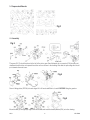
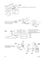
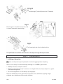
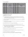
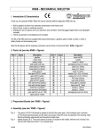
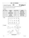
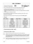
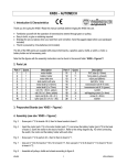
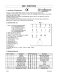
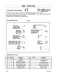
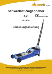
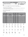
KNS1 – TYRANNOMECH
1. Introduction & Characteristics
Dispose of this product in accordance with local and national disposal regulations.
Thank you for buying the KNS1! Read this manual carefully before bringing the KNS1 into use.
• Easy to build, no glue or soldering required.
• Dislodge pre-cut pieces when you need them ; not before! Sand any jagged edges before use (sandpaper included)
• The kit is powered by 2 AA-batteries (not included).
The kits of the KNS-series are supplied with prepunched boards, a gearbox, gears, shafts, a switch, a motor, a
battery holder and all necessary parts.
2. Parts List
Part n°
1
2
3
4
5
6
7
8
9
10
11
12
13
14
15
Quant.
1
1
1
1
1
1
1
1
1
2
2
4
6
1
1
Description
gearbox
motor 3Vdc
pinion gear 8T
gear 40T/0T (white)
gear 40T/10T (red)
gear 40T/10T (green)
face gear 36T/10T (white)
metal shaft (3 x 52mm)
metal shaft (2 x 40mm)
nylon post (small)
nylon pad
nylon post (large)
nylon pad (Ø8mm)
wire with terminal (yellow)
wire with terminal (green)
Part n°
16
17
18
19
20
21
22
23
24
25
26
27
28
29
Quant.
1
1
2
2
28
4
2
6
2
3
2
6
2
2
Description
battery holder
slide switch with wire
wire (7cm)
nut M2
self-tapping screw (2 x 4mm)
self-tapping screw
screw
washer
spring
PVC tube (15mm)
metal foot (U-shaped)
fixing plate (large)
fixing plate (small)
nylon connector
Fig.1
KNS1
-1-
VELLEMAN
3. Prepunched Boards
Fig.2
4. Assembly
Fig.3
The gears (P4-7) should be placed to the left of the pinion gear. One N-shaped nylon connector (P29) should point
downward and the other one upward. Insert the motor as shown in the drawing. Note that the protruding side should
point towards the metal case.
Fig.4
Screw 2 fixing plates (P27/28) to board edges A1 & A2 and screw them to board X BEFORE fitting the gearbox.
Fig.5
Mount the left (V) and right (W) legs to the side boards and install the battery holder (P16) as in the drawing.
KNS1
-2-
VELLEMAN
Fig.6
Use an “L”-fixing plate (P27) to connect boards R and X.
Fig.7
Slide board S onto board X and screw
switch P17 onto board S. Use 1 fixing plate
P27 to fix boards S and X.
Insert one wire in the PVC tube
(P25), twist the two wires and cover
the joint with the PVC tube.
Make sure the wiring is correct !!!
1. green
2. red
3. yellow
4. red
5. black
Fig.8
Fig.9
Screw a fixing plate P27 to boards
Y and Z first and then attach them
to boards B and C.
KNS1
-3-
VELLEMAN
Fig.10
Mount the right (T) and left (U) arms to the Y/Z assembly.
Fig.11
Mount the arms to board S and use the wire (n°18)
to connect Tyrannomech’s arms and legs.
Fig.12
Fix all remaining boards in their indicated positions.
The specifications and contents of this manual can be subject to change without prior notice.
KNS1 – TYRANNOMECH
1. Inleiding en Kenmerken
Ontdoe u van dit product volgens de plaatselijke en nationale regelgeving inzake verwijdering.
Dank u voor uw aankoop! Lees deze handleiding aandachtig voor u de KNS1 in gebruik neemt.
• Makkelijk te bouwen, zonder lijm of solderen.
• Maak de voorgesneden vormen pas los wanneer u ze nodig hebt. Schuur de scherpe randjes af voor gebruik
(schuurpapier meegeleverd)
• De kit wordt aangedreven door 2 AA-batterijen (niet inbegrepen).
De kits van de KNS-reeks worden geleverd met voorgesneden vormen, tandwielkast, koppeling, stangen,
schakelaar, motor, batterijhouder en alle vereiste onderdelen.
KNS1
-4-
VELLEMAN
2. Lijst van Onderdelen
Nr.
1
2
3
4
5
6
7
8
9
10
11
12
13
14
15
Hoev.
1
1
1
1
1
1
1
1
1
2
2
4
6
1
1
Beschrijving
tandwielkast
motor 3Vdc
rondsel 8T
tandwiel 40T/0T (wit)
tandwiel 40T/10T (rood)
tandwiel 40T/10T (groen)
tandwiel 36T/10T (wit)
metalen as (3 x 52mm)
metalen as (2 x 40mm)
nylon ring (klein)
nylon kraagring
nylon ring (groot)
nylon kraagring (Ø8mm)
draad met connector (geel)
draad met connector (groen)
Nr.
16
17
18
19
20
21
22
23
24
25
26
27
28
29
Hoev.
1
1
2
2
28
4
2
6
2
3
2
6
2
2
Beschrijving
batterijhouder
schuifschakelaar met draad
draad (7cm)
moer M2
zelftappende schroef (2 x 4mm)
zelftappende schroef
schroef
borgring
veer
PVC buis (15mm)
metalen voet (U-vormig)
bevestigingsplaat (groot)
bevestigingsplaat (klein)
nylon connector
3. Voorgesneden vormen (zie fig.2 blz.2)
4. Montage (zie blz.2-4 voor de figuren)
Fig. 3: Plaats de tandwielen (P4-7) links van het rondsel. Richt de ene N-vormige nylon connector (P29) naar
beneden en de andere naar boven. Breng de motor aan volgens de tekening. Merk op dat de uitstekende
kant naar de metalen behuizing moet worden gericht.
Fig. 4: Schroef 2 bevestigingsplaten (P27/28) vast aan de randen A1 en A2 en monteer deze op plaat X VOOR u de
tandwielkast monteert.
Fig. 5: Monteer het linker-(V) en rechterbeen (W) op de randen A1 en A2 van plaat X en monteer de batterijhouder
(P16) op plaat X zoals in de tekening.
Fig. 6: Verbind platen R en X d.m.v. één L-vormige bevestigingsplaat (P27).
Fig. 7: Schuif plaat S op plaat X en schroef schakelaar P17 op plaat S. Maak plaat S & X vast met 1 x P27.
Fig. 8: Stop 1 draad in de PVC buis (P25), draai de twee draden samen en schuif de PVC buis over de verbinding.
Zorg dat de bedrading correct is aangesloten !!!
1. groen - 2. rood - 3. geel - 4. rood - 5. zwart
Fig. 9: Schroef een bevestigingsplaat (P27) vast aan platen Y & Z en maak ze dan vast aan platen B en C.
Fig. 10: Monteer de rechter- (T) en linkerarm (U) op de platen Y en Z.
Fig. 11: Bevestig de armen op plaat S en verbind de armen en de poten van de Tyrannomech met draad P18.
Fig. 12: Breng de overige platen aan op de aangegeven plaats.
De inhoud van deze handleiding kan worden gewijzigd zonder voorafgaande kennisgeving.
KNS1
-5-
VELLEMAN
KNS1 – TYRANNOMECH
1. Introduction et Caractéristiques
Débarrassez-vous de ce produit en respectant la législation d'élimination locale et nationale.
Nous vous remercions de votre achat ! Lisez la notice présente attentivement avant la mise en service du KNS1.
• Facile à assembler, sans colle ou soudage.
• Ne détachez les pièces prédécoupées qu’au moment où vous en avez besoin. Polissez les arêtes avant
d’employer la pièce en question (papier d’émeri inclus)
• Le kit est piloté par 2 piles AA (non incluses).
Les kits de la série KNS sont livrés avec : éléments prédécoupés en bois, pignons, tiges, interrupteur, moteur, portepiles et toutes les pièces nécessaires.
2. Liste des pièces
Pièce
1
2
3
4
5
6
7
8
9
10
11
12
13
14
15
Quant.
1
1
1
1
1
1
1
1
1
2
2
4
6
1
1
Description
boîte d’engrenages
moteur 3Vdc
satellite 8T
pignon 40T/0T (blanc)
pignon 40T/10T (rouge)
pignon 40T/10T (vert)
pignon 36T/10T (blanc)
axe métallique (3 x 52mm)
axe métallique (2 x 40mm)
embout en nylon (petit)
canon en nylon
embout en nylon (grand)
canon en nylon (Ø8mm)
fil avec connecteur (jaune)
fil avec connecteur (vert)
Pièce
16
17
18
19
20
21
22
23
24
25
26
27
28
29
Quant.
1
1
2
2
28
4
2
6
2
3
2
6
2
2
Description
porte-piles
glissière avec fil
fil (7cm)
écrou M2
vis taraudeuse (2 x 4mm)
vis taraudeuse
vis
rondelle de serrage
ressort
tube en PVC (15mm)
base métallique en "U"
crochet de fixation (grand)
crochet de fixation (petit)
connecteur en nylon
3. Pièces prédécoupées (voir fig.2 à la p.2)
4. Montage (voir p.2-4 pour les figures)
Fig. 3: Positionnez les pignons (P4-7) à gauche du satellite. Le premier connecteur ”N” en nylon (P29) est dirigé vers
le bas et l’autre en haut. Installez le moteur selon la figure. Remarquez que la protubérance doit pointer vers le
boîtier métallique.
Fig. 4: Vissez 2 crochets de fixation (P27/28) sur les panneaux A1 et A2 et fixez ceux-ci au panneau X AVANT de
monter la boîte d’engrenages.
Fig. 5: Montez les jambes gauche (V) et droite (W) aux bords A1 et A2 du panneau X et montez le porte-piles (P16)
sur le panneau X comme dans la figure.
Fig. 6: Fixez le panneau R au panneau X à l’aide d’un crochet de fixation (P27).
KNS1
-6-
VELLEMAN
Fig. 7: Mettez panneau S sur panneau X et vissez commutateur P17 sur panneau S. Fixez panneaux S et X avec 1
crochet de fixation P27.
Fig. 8: Insérez 1 fil dans le tube en PVC (P25), tressez les deux fils et recouvrez le joint à l’aide du tube.
Veillez à ce que le câblage soit correctement connecté!!!
1. vert - 2. rouge - 3. jaune - 4. rouge - 5. noir
Fig. 9: Vissez d’abord un crochet de fixation (P27) aux panneaux Y et Z et vissez-les sur les panneaux B et C.
Fig. 10: Montez les bras droite (T) et gauche (U) sur les panneaux Y et Z.
Fig. 11: Montez les bras sur le panneau S et liez les bras et les pattes du Tyrannomech avec fil P18.
Fig. 12: Montez les panneaux restants selon la figure.
Les spécifications et le contenu de cette notice peuvent être modifiées sans notification préalable.
KNS1 – TYRANNOMECH
1. Introducción y Características
Tire el aparato defectuoso en los correspondientes depósitos de eliminación de residuos según las leyes locales y nacionales.
¡Gracias por haber comprado el KNS1! Lea cuidadosamente las instrucciones del manual antes de montarlo.
• Fácil construcción, sin cola ni soldadura.
• Sólo separe las piezas previamente cortadas si las necesita. Lije los bordes dentados antes de usar la pieza
(papel de lija incluido)
• El kit funciona con 2 pilas AA (no incluidas).
Los kits de la serie KNS se entregan con: piezas de madera precortadas, piñones, ejes, interruptor, motor, portapilas
y todas las piezas necesarias.
2. Lista de piezas
Pieza
1
2
3
4
5
6
7
8
9
10
11
12
13
14
15
KNS1
Cantidad
1
1
1
1
1
1
1
1
1
2
2
4
6
1
1
Descripción
caja de engranajes
moto 3Vdc
satélite 8T
piñón 40T/0T (blanco)
piñón 40T/10T (rojo)
piñón 40T/10T (verde)
piñón 36T/10T (blanco)
eje metálico (3 x 52mm)
eje metálico (2 x 40mm)
anillo de nylon (pequeño)
cañón de nylon
anillo de nylon (grande)
cañón de nylon (Ø8mm)
hilo con conector (amarillo)
hilo con conector (verde)
Pieza
16
17
18
19
20
21
22
23
24
25
26
27
28
29
-7-
Cantidad
1
1
2
2
28
4
2
6
2
3
2
6
2
2
Descripción
portapilas
conmutador deslizante con hilo
hilo (7cm)
tuerca M2
tornillo autoroscante (2 x 4mm)
tornillo autoroscante
tornillo
arandela de ajuste
resorte
tubo de PVC (15mm)
base metálica en forma de "U"
gancho de fijación (grande)
gancho de fijación (pequeño)
conector de nylon
VELLEMAN
3. Piezas precortadas (véase fig.2 en la p.2)
4. Montaje (véase p.2-4 para las figuras)
Fig. 3: Coloque los piñones (P4-7) a la izquierda del satélite. Apunte el primer conector ”N” de nylon (P29) hacia
abajo y el otro hacia arriba. Instale el motor según la figura. Preste atención a que el saliente apunte hacia la
caja metálica.
Fig. 4: Atornille 2 ganchos de fijación (P27/28) en los paneles A1 y A2 y fíjelos a los paneles X ANTES de montar la
caja de engranajes.
Fig. 5: Monte la pata izquierda (V) y derecha (W) a los bordes A1 y A2 del panel X y monte el portapilas (P16) en el
panel X como se indica en la figura.
Fig. 6: Conecte los paneles R y X con el panel de fijación en forma de “L” (P27).
Fig. 7: Coloque panel S en panel X y atornille conmutador P17 en panel S. Fije los paneles S y X con 1 gancho de
fijación P27.
Fig. 8: Introduzca 1 hilo en el tubo de PVC (P25), trence los dos hilos y cubre la junta con el tubo de PVC.
¡¡¡Asegúrese de que el cableado esté correctamente conectado!!!
1. verde - 2. rojo - 3. amarillo - 4. rojo - 5. negro
Fig. 9: Primero, atornillo un gancho de fijación (P27) a los paneles Y y Z y atorníllelos en los paneles B y C.
Fig. 10: Monte el brazo derecho (T) e izquierdo (U) en los paneles Y y Z.
Fig. 11: Monte los brazos en el panel S y une los brazos y las patas del Tyrannomech con el hilo P18.
Fig. 12: Monte las piezas restantes según la figura.
Se pueden modificar las especificaciones y el contenido de este manual sin previo aviso.
KNS1 – TYRANNOMECH
1. Einführung und Eigenschaften
Entsorgen Sie dieses Produkt gemäß der örtlichen und nationalen Gesetzgebung bezüglich Entsorgung.
Danke für Ihren Ankauf ! Lesen Sie vor der Inbetriebnahme des KNS1 diese Bedienungsanleitung sorgfältig durch !
• Einfach zusammenzubauen, ohne Leimen oder Löten.
• Entfernen Sie die vorgeschnittenen Formen erst dann wenn Sie sie brauchen. Schmirgeln Sie die scharfen
Kanten vor Gebrauch (Schleifpapier mitgeliefert).
• Der Bausatz arbeitet mit 2 AA-Batterien (nicht mitgeliefert).
Die Bausätze der KNS-Serie werden mit vorgeschnittenen Formen, einem Getriebe, Zahnrädern, Achsen, einem
Schalter, einem Motor, einem Batteriehalter und allen erforderlichen Teilen geliefert.
KNS1
-8-
VELLEMAN
2. Stückliste
Nr.
1
2
3
4
5
6
7
8
9
10
11
12
13
14
15
St.
1
1
1
1
1
1
1
1
1
2
2
4
6
1
1
Beschreibung
Getriebe
Motor 3Vdc
Ritzel 8T
Zahnrad 40T/0T (weiß)
Zahnrad 40T/10T (rot)
Zahnrad 40T/10T (grün)
Zahnrad 36T/10T (weiß)
Metallachse (3 x 52mm)
Metallachse (2 x 40mm)
Nylonring (klein)
Nylonanschluss
Nylonring (groß)
Nylonanschluss (Ø8mm)
Draht mit Anschluss (gelb)
Draht mit Anschluss (grün)
Nr.
16
17
18
19
20
21
22
23
24
25
26
27
28
29
St.
1
1
2
2
28
4
2
6
2
3
2
6
2
2
Beschreibung
Batteriehalter
Schiebeschalter mit Draht
Draht (7cm)
Mutter M2
Schneidschraube (2 x 4mm)
Schneidschraube
Schraube
Unterlegscheibe
Feder
PVC-Rohr (15mm)
Metallfuß (U-förmig)
Befestigungsplatte (groß)
Befestigungsplatte (klein)
Nylonanschluss
3. Vorgeschnittene Teile (siehe “ Abb.2 Seite 2)
4. Zusammenbau (siehe Seiten 2-4 für die Abbildungen)
Abb. 3: Stellen Sie die Zahnräder (Nr. 4-7) links vom Ritzel. Richten Sie den einen N-förmigen Nylonanschluss (Nr.
14) nach unten und den anderen nach oben. Montieren Sie den Motor gemäß Abbildung. Beachten Sie, dass
der herausragende Rand auf das Metallgehäuse gerichtet sein muss.
Abb. 4: Schrauben Sie die 2 Befestigungsplatten (Nr. 27/28) an den Rändern A1 und A2 fest und montieren Sie
diese auf Platte X BEVOR Sie das Getriebe montieren.
Abb. 5: Montieren Sie die das linke (V) und das rechte Bein (W) an den Rändern A1 und A2 der Platte X und
montieren Sie den Batteriehalter (Nr. 16) auf Platte X (siehe Abbildung).
Abb. 6: Verbinden Sie die Platten R und X mit einer L-förmigen Befestigungsplatte (Nr. 27).
Abb. 7: Schrauben Sie Platte S auf Platte X und schrauben Sie Schalter Nr. 17 auf Platte S. Machen Sie Platte S & X
mit 1 x Nr. 27 fest.
Abb. 8: Stecken Sie einen Draht in das PVC-Rohr (Nr. 25), drehen Sie die zwei Drähte zusammen und schieben Sie
das PVC-Rohr über die Verbindung.
Achten Sie darauf, dass die Verkabelung richtig angeschlossen ist !!!
1. grün - 2. rot - 3. gelb - 4. rot - 5. schwarz
Abb. 9: Schrauben Sie die Befestigungsplatte (Nr. 27) an Platten Y & Z fest und schrauben Sie diese zunächst an
Platten B und C fest.
Abb. 10: Montieren Sie den rechten (T) und linken Arm (U) an Platten Y und Z.
Abb. 11: Befestigen Sie die Arme an Platte S und verbinden Sie die Arme und Beine des Tyrannomechs mit dem
Draht Nr. 18.
Abb. 12: Bringen Sie die übrigen Platten an der angegebenen Stelle an.
Alle Änderungen vorbehalten.
KNS1
-9-
VELLEMAN