1
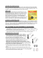
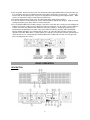
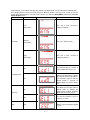
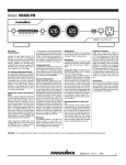
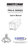
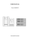
User’s Manual
OR1500PFCRT2U / OR2200PFCRT2U / OR2200PFCRT2Ua
K01-0000155-00
IMPORTANT SAFETY INSTRUCTIONS
(SAVE THESE INSTRUCTIONS)
This manual contains important safety instructions. Please read and follow all instructions carefully during
installation and operation of the unit. Read this manual thoroughly before attempting to unpack, install, or
operate your UPS.
CAUTION! To prevent the risk of fire or electric shock, install in a temperature and humidity controlled indoor
area free of conductive contaminants. (Please see specifications for acceptable temperature and humidity
range).
CAUTION! To reduce the risk of electric shock, do not remove the cover except to service the battery. Ensure
the input power is removed before servicing the batteries. There are no user serviceable parts inside except for
the battery.
CAUTION! Hazardous live parts inside can be energized by the battery even when the AC input power is
disconnected.
CAUTION! The UPS must be connected to an AC power outlet with fuse or circuit breaker protection. Do
not plug into an outlet that is not grounded. If you need to de-energize this equipment, turn off and unplug the
unit.
CAUTION! To avoid electric shock, turn off the unit and unplug it from the AC power source before servicing
the battery or installing a computer component.
CAUTION! To reduce the risk of fire, connect only to a circuit provided with 20 (OR1500PFCRT2U and
OR2200PFCRT2U) or 30 (OR2200PFCRT2Ua) amperes maximum branch circuit over current protection in
accordance with the National Electric Code, ANSI/NFPA 70.
CAUTION! The UPS is suitable for use in a computer room as defined in the Standard for the Protection of
Electronic Computer/Data Processing Equipment, ANSI/NFPA 75.
DO NOT USE FOR MEDICAL OR LIFE SUPPORT EQUIPMENT! CyberPower Systems does not sell
products for life support or medical applications. DO NOT use in any circumstance that would affect the
operation and safety of life support equipment, medical applications, or patient care.
DO NOT USE WITH OR NEAR AQUARIUMS! To reduce the risk of fire or electric shock, do not use with or
near an aquarium. Condensation from the aquarium can cause the unit to short out.
INSTALLING YOUR UPS SYSTEM
INTRODUCTION
Thank you for selecting a CyberPower Systems UPS product. This UPS is designed to provide unsurpassed
power protection, operation and performance during the lifetime of the product.
UNPACKING
Inspect the UPS upon receipt. The box should contain the following:
(a) UPS unit x 1 (b) User’s manual x 1 (c) Rack mount brackets x 2 (d) Vertical stands x 2 (e) Telephone cable x
1 (f) Emergency Power Off cable (gray) x 1 (g) PowerPanel® Business Edition software CD x 1 (h) Serial cable
x 2 (i) USB A+B type cable x 1 (j) Warranty registration card x 1
2
SUPPORTS PFC POWER SUPPLIES
This CyberPower UPS system supports High Efficiency power supplies with Power Factor Correction (PFC).
PFC is used to improve the efficiency of power delivery. The current US Energy Star® Program Requirements
for Computers (version 5.0) mandates PFC for all power supplies over 100 watts. Additionally, programs such
as 80 Plus® are often used to identify high efficiency power supplies with PFC.
WHAT IS AVR
The OR1500PFCRT2U/OR2200PFCRT2U/OR2200PFCRT2Ua provides
complete power protection from utility power that is not always consistent.
The OR1500PFCRT2U features 1840 Joules of surge protection and the
OR2200PFCRT2U/OR2200PFCRT2Ua features 2060 Joules of surge
protection. Both units provide long lasting battery backup during power
outages with maintenance free batteries. The OR1500PFCRT2U /
OR2200PFCRT2U / OR2200PFCRT2Ua ensures consistent power to your
computer system and includes software that will automatically save your
open files and shutdown your computer system during a utility power loss.
AUTOMATIC VOLTAGE REGULATOR
The OR1500PFCRT2U/OR2200PFCRT2U/OR2200PFCRT2Ua stabilizes inconsistent utility power voltage to
nominal levels that are safe for equipment. Inconsistent incoming utility power may be damaging to important
data files and hardware, but with Automatic Voltage Regulation (AVR), damaging voltage levels are corrected
to safe levels. AVR automatically increases low utility power and decreases high utility power to a consistent
and safe 110/120 volts. If incoming utility voltage drops below 90 volts, or exceeds 140 volts the units
automatically switch to battery back-up power.
HOW TO DETERMINE THE POWER REQUIREMENTS OF YOUR EQUIPMENT
1. Ensure that the equipment plugged into the outlet does not exceed the UPS unit’s rated capacity
(1500VA/900W for OR1500PFCRT2U, 2000VA/1320W for OR2200PFCRT2U, and 2200VA/1320W for
OR2200PFCRT2Ua). If the rated capacities of the unit are exceeded, an overload condition may occur and
cause the UPS unit to shut down or the circuit breaker to trip.
2. There are many factors that can affect the amount of power that your computer system will require. It is
suggested that the load placed on the battery outlets not exceed 80% of the unit’s capacity.
HARDWARE INSTALLATION GUIDE
1. Your new UPS may be used immediately upon receipt. However,
recharging the battery for at least 8 hours is highly recommended
to ensure that the battery’s maximum charge capacity is achieved.
A loss of charge may occur during shipping and storage. To recharge
the battery, simply leave the unit plugged into an AC outlet.
2. With the UPS unit turned off and unplugged, connect your computer,
monitor, and any other peripherals requiring battery backup into the
battery power supplied outlets. For pluggable equipment, the socket-outlet
shall be installed near the equipment and shall be easily accessible.
DO NOT plug a laser printer, paper shredder, copier, space heater, vacuum,
sump pump or other large electrical devices into the UPS. The power demands
of these devices may overload and damage the unit.
3. To protect a fax, phone or modem, connect a telephone cable or network cable from
the wall jack outlet to the IN jack of the UPS. Connect a telephone cable or network
cable from the OUT jack of the UPS to a fax machine, telephone, modem, or network
devices.
4. Plug the UPS into a 2 pole, 3 wire grounded receptacle (wall outlet). Make sure the
wall branch outlet is protected by a fuse or circuit breaker and does not service equipment
with large electrical demands (e.g. air conditioner, copier, etc…). The warranty prohibits
the use of extension cords, outlet strips, and surge strips.
3
5. Press the power switch to turn the unit on. The Power On indicator light will illuminate and the unit will “beep”.
If an overload is detected, an audible alarm will sound and the unit will emit one long beep. To correct this,
turn the UPS off and unplug at least one piece of equipment from the battery power supplied outlets. Make
sure the circuit breaker is depressed and then turn the UPS on.
6. To maintain optimal battery charge, leave the UPS plugged into an AC outlet at all times.
7. To store the UPS for an extended period, cover it and store with the battery fully charged. While in storage,
recharge the battery every three months to ensure battery life.
8. To use PowerPanel® Business Edition software, connect the serial cable to the serial port or the USB port on
both the UPS and the computer. These OR units include one serial port, one dry contact, and one USB port
to allow connection and communication between the UPS and computers. Serial port II produces basic
information for equipment that can utilize a dry contact UPS. The primary computer (with PowerPanel®
Business Edition installed) is the computer that you will use to control the UPS and make changes to the
operation of the UPS. When there is a power failure, the computer connected to the Primary port will start to
shut down after a user controlled delay. PowerPanel® Business Edition will save and close any open files
prior to shutting down the system.
BASIC OPERATION
DESCRIPTION
4
Power Switch
Master on/off switch for equipment connected to the UPS.
Power On Indicator (blue)
This LED is illuminated when the utility power is normal and the UPS outlets are providing power, free of
surges and spikes.
LCD module display
Intelligent LCD panel shows all the UPS information using icons and messages. For more information
please review the “Definitions for Illuminated LCD Indicators” section below.
LCD function selection switch
The switch can be used to select the LCD display contents including input/output voltage and estimated run
time, etc.
8 Full Time Battery Powered and Surge Protected Outlets
The unit has eight battery powered/surge suppression outlets for connected equipments to ensure
temporary uninterrupted operation of your equipment during a power failure. (DO NOT plug a laser printer,
paper shredder, copier, space heater, vacuum, sump pump or other large electrical devices into the UPS.
The power demands of these devices may overload and damage the unit.)
AC Input Power Cord
Heavy-duty, extra long power cord.
Output Circuit Breaker
Resettable circuit breakers provide output optimal overload protection.
Input Circuit Breaker
Resettable circuit breakers provide input optimal overload protection.
USB Port
The USB port allows connection and communication between the USB port on the computer and the UPS
unit.
Communication Protection Ports
Communication protection ports will protect any standard modem, fax, telephone line, network or Ethernet
connection (RJ11/RJ45).
⑪ Wiring Fault Indicator (red)
This LED indicator will illuminate to warn the user that a wiring problem exists, such as bad ground, missing
ground or reversed wiring. If this is illuminated, disconnect all electrical equipments from the outlet and
have an electrician verify the outlet is properly wired. The unit will not provide surge protection without being
plugged into a grounded and properly wired wall outlet.
⑫ Coax/Cable/DSS Surge Protection
The Coax/Cable/DSS surge protection ports will protect any cable modem, CATV converter, or DSS
receiver.
⑬ Serial Port I (Primary)
The serial port allows connection and communication between the UPS and the computer.
⑭ Serial Port II (Dry Contact)
Dry contact produces information for equipment that can utilize dry contact signals.
⑮ EPO (Emergency Power Off) Port:
Use the provided gray cable to connect to a special EPO
contact switch. Follow the appropriate circuit diagram below
to wire the cable to your EPO configuration. The EPO remote
switch is a switch installed in an outside area, connected to
the unit via the Emergency Power Off cable. In case of an
emergency, it can be used to immediately cut-off power from
the UPS.
⑯ SNMP/HTTP Network Slot:
Remove the cover panel to install an optional RMCARD to
remotely monitor and manage your UPS over a network.
5
BATTERY REPLACEMENT
REPLACING THE BATTERY
Read and follow the IMPORTANT SAFETY INSTRUCTIONS before servicing the battery. CAUTION!
Servicing of the battery should only be performed by trained personnel familiar with batteries and their
precautions. For more information on battery replacement, contact your dealer or call the number on
this manual.
Replacement of batteries located in an OPERATOR ACCESS AREA.
1. When replacing batteries, replace with the same number of the following battery: CyberPower RBP433 for
the OR1500PFCRT2U; CyberPower RBP435 for the OR2200PFCRT2U and OR2200PFCRT2Ua.
2. CAUTION! Risk of Energy Hazard, 12 V, maximum 7(for the OR1500PFCRT2U) or 8.5 (for the
OR2200PFCRT2U and OR2200PFCRT2Ua) Ampere-hour battery. Before replacing batteries, remove
conductive jewelry such as chains, wrist watches, and rings. High energy conducted through these
materials could cause severe burns;
3. CAUTION! Do not dispose of batteries in a fire. The batteries may explode;
4. CAUTION! Do not open or mutilate batteries. Released material is harmful to the skin and eyes. It may
be toxic.
CAUTION - RISK OF EXPLOSION IF BATTERY IS REPLACED BY AN INCORRECT TYPE. DISPOSE OF
USED BATTERIES ACCORDING TO LOCAL REGULATIONS.
BATTERY REPLACEMENT PROCEDURE:
Remove the right side front panel.
Remove the three retaining screws of
the cable protection cover then
remove the cover.
Remove the four retaining screws.
Insert the new battery pack. Assemble the screws, cover, cable and front panel in the reverse
sequence of above steps. Recharge the unit for 4-8 hours to ensure the UPS performs
expected runtime.
Disconnect the black and red cable.
REMINDER: Batteries are considered HAZARDOUS WASTE and must be disposed of properly. Most
retailers that sell lead-acid batteries collect used batteries for recycling, as required by local regulations.
6
DEFINITION FOR ILLUMINATED LCD INDICATORS
1. INPUT voltage meter: This meter measures the AC voltage that the UPS
system is receiving from the utility wall outlet. The UPS is designed,
through the use of automatic voltage regulation, to continuously correct
output voltage to connected equipment to a safe 110/120 voltage output
range. In the event of a complete power loss, severe brownout, or
over-voltage, the UPS relies on its internal battery to supply consistent
110/120 output voltage. The INPUT voltage meter can be used as a
diagnostic tool to identify poor-quality input power.
2. OUTPUT voltage meter: This meter measures, in real time, the AC
voltage that the UPS system is providing to the computer, such as
normal line mode, AVR mode, and battery backup mode. (Note: The
OUTPUT voltage meter shows the status of the battery backup outlets.)
3. ESTIMATED RUN TIME: This displays the run time estimate of the UPS with current battery capacity and
load.
4. NORMAL icon: This icon appears when the UPS is working under normal conditions.
5. BATTERY icon: During a severe brownout or blackout, this icon appears and an alarm sounds (two short
beeps followed by a pause) to indicate the UPS is operating from its internal batteries. During a prolonged
brownout or blackout, the alarm will beep rapidly every 1/2 second (and the BATT.CAPACITY meter shows
one 20% capacity segment shaded. The capacity depends on how much load added and the runtime left.
You can setup the Low Battery Threshold through PowerPanel® Business Edition software.) to indicate the
UPS’s batteries are nearly out of power. You should save files and turn off your equipment immediately or
allow the software to shut the system down.
6. AVR (Automatic Voltage Regulation) icon: This icon appears whenever your UPS is automatically
correcting low AC line voltage without using battery power. This is a normal, automatic operation of your
UPS, and no action is required on your part.
7. SILENT MODE icon: This icon appears whenever the UPS is in silent mode. The buzzer does not beep
during silent mode until the battery reaches low capacity.
8. OVER LOAD icon: This icon appears and an alarm sounds to indicate the battery-supplied outlets are
overloaded. To clear the overload, unplug some of your equipment from the battery-supplied outlets until
the icon turns off and the alarm stops.
9. FAULT icon: This icon appears if there is a problem with the UPS, Contact CyberPower Systems at
[email protected] for further help and support.
F01: Battery Mode or Line Mode Overload fault
F02: Battery Output Short fault
F03: Charger Fault
F04: Internal Fault
10. BATT. CAPACITY meter: This meter displays the approximate charge level (in 20% increments) of the
UPS’s internal battery. During a blackout or severe brownout, the UPS switches to battery power, the
BATTERY icon appears, and the charge level decreases.
11. LOAD CAPACITY meter: This meter displays the approximate output load level (in 20% increments) of
the UPS battery outlets.
Advanced LCD Functions Setup
There are advanced LCD functions that can be setup through LCD Display button. (1) Mute: Enable or disable
any audible alarm caused by an event. (2) Sensitivity: Control the sensitivity of the UPS to switch to Battery
Mode by selecting UPS shutdown voltage range. The higher the sensitivity, the easier the UPS will switch to
Battery Mode. (3) LCD Always On: Keep the LCD always lit. (4) Self Test: Perform a test in Line Mode to test
Battery Mode function. It will return to Line Mode after the test is completed. (5) ESC: Leave setup mode
without changing any settings and return to LCD status display screen.
For the Mute function, press Display button for 2 seconds to enable or disable audible alarm. When
you enable audible alarm, the Silent icon is not lit. When you disable audible alarm, the Silent icon is lit.
For the Sensitivity, LCD Always On, Self Test, and ESC functions, press Display button for 8 seconds to
enter Function Setup screen. Press Display button once to choose between Sensitivity, LCD Always On, Self
Test, and ESC Functions. When the function is chosen, press 2 seconds to enter Mode Setup screen. (or If the
function you select is ESC, press 2 seconds and you will leave the Function Setup screen and return to LCD
7
Status Display screen without changing any settings.) The Mode details are described in the following table.
Press Display button to choose the mode you prefer. When the mode is chosen, press 8 seconds to save the
setting. If the Display button is not touched for 3 minutes, you will leave Setup Mode and return to UPS LCD
Status Display screen.
Function Setup
Mode Setup
Icon
Description
Sensitivity
Low
(86-142Vac)
This unit is least sensitive to
voltage fluctuations.
Medium
(88-139Vac)
This is the default setting.
High
(90-136Vac)
This unit is most sensitive to
voltage fluctuations.
On
The LCD is always on, whether or
not the LCD button is pressed.
Off
In Line Mode, if the LCD display
button is not touched for 1 minute,
the UPS will enter Sleeping Mode.
The LCD will not appear until the
display button is pressed. In
Battery Mode, the LCD is always
on.
On
The Self Test function is on. In
Line Mode, the UPS will switch to
battery mode to simulate the
power failure condition. In Battery
Mode, the UPS has no action.
Off
The Self Test function is off. The
UPS has no action.
N/A
Return to the LCD Status Display
screen.
LCD Always On
Self Test
ESC
8
DEFINITION FOR LCD ICONS & AUDIBLE INDICATION
CONDITION
Alarm
On
Off
Off
Off
On
Off
Off
On
Off
Rapid Beeping
every 1/2 second
Off
On
On
Constant tone
Off
Beeps twice
every 30 seconds
Normal
Utility Failure - The UPS is providing power to
battery power-supplied outlets from its battery.
Utility Failure - The UPS is providing battery
power. Rapid beeping indicates the unit will
run out of power shortly.
Battery Overload - Occurs when connected
equipment exceeds the listed capacity of the
UPS. Turn the UPS off, unplug at least one
piece of equipment from battery outlets, wait 10
seconds, reset the circuit breaker and turn the
unit on.
TROUBLESHOOTING
Problem
Possible Cause
Circuit breaker button is
projecting from the side of
the unit.
Circuit breaker has tripped due
to an overload.
Battery not fully charged.
The UPS does not perform
expected runtime.
Battery is worn out.
The on/off switch is designed
to prevent damage from rapidly
turning it off and on.
The unit is not connected to an
AC outlet.
Solution
Turn the UPS off and unplug at least one
piece of equipment. Wait 10 seconds, reset
the circuit breaker by depressing the button,
and then turn the UPS on.
Recharge the battery by leaving the UPS
plugged in.
Contact CyberPower Systems about
replacement batteries at
[email protected]
Turn the UPS off.
turn the UPS on.
Wait 10 seconds and then
The unit must be connected to a 110/120V
60Hz outlet.
The UPS will not turn on.
Contact CyberPower Systems about
The battery is worn out.
replacement batteries at
[email protected]
Contact CyberPower Systems at
Mechanical problem.
[email protected]
Connect the USB / serial cable to the UPS
The USB / serial cable is not
unit and an open USB / serial port on the
connected.
back of the computer. You must use the
cable that came with the unit.
Check the back of the computer for an
®
The USB / serial cable is
PowerPanel Business
additional USB / serial port. Move the cable
connected to the wrong port.
Edition is inactive (all
to this port.
icons are gray).
Shutdown your computer and turn the UPS
The unit is not providing
off. Wait 10 seconds and turn the UPS back
battery power.
on. This should reset the unit.
The serial cable is not the
Please use the serial cable that came with the
cable that came with the unit.
unit for the software.
Additional troubleshooting information can be found under “Support” at
www.CPSww.com
9
TECHNICAL SPECIFICATIONS
Model
OR1500PFCRT2U
OR2200PFCRT2U
OR2200PFCRT2Ua
Capacity
1500VA / 900W
2000VA / 1320W
2200VA/1320W
Nominal Input Voltage
120V
Input Frequency
47 Hz to 63 Hz
On-Battery Output
Voltage
120Vac ± 5%
Transfer Time
4ms Typical
Max. Load for UPS
Outlets (8 Outlets)
1500VA / 900W
2000VA / 1320W
2200VA/1320W
Max. Load for Full-Time
Surge Protection outlets
(8 Outlets)
12.5 Amps
16.7 Amps
18.3 Amps
On-Battery Output Wave
Form
Sine Wave
Operating Temperature
+ 32°F to 104° F / 0° C to 40° C
Operating Relative
Humidity
0 to 90% non-condensing
Size (L x W x H)
433 x 388 x 88 mm (2U Rack)
17” x 15.3” x 3.5”
Net Weight
55.1lbs / 25kg
59.3lbs / 26.9kg
60lbs / 27.2kg
Battery Type
12V, 7Ah
(RBP433 / CyberPower)
12V, 8.5Ah
(RBP435 / CyberPower)
12V, 8.5Ah
(RBP435 / CyberPower)
Typical Battery
Recharge Time
8 hours from total discharge
Typical Battery Life
3 to 6 years, depending on number of discharge/recharge cycles
Recommended Battery
Sealed Maintenance Free Lead Acid Battery
Safety Approvals
UL1778, CSA C22.2 No 107.3, FCC/DoC Class B
SYSTEM FUNCTIONAL BLOCK DIAGRAM
Input
EMI
Filter
Surge
Suppressor
AVR
Charger
AC/DC
Inverter
Normal Mode
Battery Mode
Battery
10
Output
CYBERPOWER GREENPOWER UPS™ TECHNOLOGY
Advanced Energy-Saving Patented Bypass Technology
CyberPower’s patented GreenPower UPS™ with Bypass Technology reduces UPS energy
costs by up to 75% compared to conventional UPS models. Even when utility power is
normal, conventional UPS models constantly pass power through a transformer. By
contrast, under normal conditions the advanced circuitry of a GreenPower UPS™
bypasses the transformer. As a result, the power efficiency is significantly increased while
decreasing waste heat, using less energy, and reducing energy costs.
When an abnormal power condition occurs, the GreenPower UPS™ automatically runs power through its
transformer to regulate voltage and provide “safe” power. Since utility power is normal over 88% of the time, the
GreenPower UPS™ operates primarily in its efficient bypass mode.
The GreenPower UPS™ is also manufactured in accordance with the Restriction on Hazardous Substances
(RoHS) directive making it one of the most environmentally-friendly on the market today.
LIMITED WARRANTY AND CONNECTED EQUIPMENT GUARANTEE
Read
the
following
terms
and
conditions
carefully
before
using
the
CyberPower
OR1500PFCRT2U/OR2200PFCRT2U/ OR2200PFCRT2Ua (the “Product”). By using the Product you consent
to be bound by and become a party to the terms and conditions of this Limited Warranty and Connected
Equipment Guarantee (together referred to as this “Warranty”). If you do not agree to the terms and conditions
of this Warranty, you should return the Product for a full refund prior to using it.
Who is Providing this Warranty?
CyberPower Systems (USA), Inc. (“CyberPower”) provides this Limited Warranty.
What Does This Warranty Cover?
This warranty covers defects in materials and workmanship in the Product under normal use and conditions.
It also covers equipment that was connected to the Product and damaged because of the failure of the Product.
What is the Period of Coverage?
This warranty covers the Product for three years and connected equipment for as long as you own the Product.
Who Is Covered?
This warranty only covers the original purchaser.
Coverage ends if you sell or otherwise transfer the Product.
How Do You Get Service?
1. Call us at (877) 297-6937 or write to us at CyberPower Systems (USA), Inc., 4241 12th Ave. E., STE 400,
Shakopee, MN 55379 or send us an e-mail message at [email protected] for instructions.
2. When you contact CyberPower, identify the Product, the Purchase Date, and the item(s) of Connected
Equipment. Have information on all applicable insurance or other resources of recovery/payment that are
available to the Initial Customer and Request a Claim Number.
3. You must provide a dated Proof-of-Purchase receipt (or other proof of the original purchase) and provide a
description of the defect.
4. Pack and ship the product to CyberPower and, if requested, the item(s) of Connected Equipment, a repair
cost estimate for the damage to the Connected Equipment, and all claim forms that CyberPower provides
to you. Show the Claim Number on the shipping label or include it with the product. You must prepay all
shipping costs, you are responsible for packaging and shipment, and you must pay the cost of the
repair estimate.
How Long Do I Have To Make A Claim?
All claims must be made within ten days of the occurrence.
11
What Will We Do To Correct Problems?
CyberPower will inspect and examine the Product.
If the Product is defective in material or workmanship, CyberPower will repair or replace it at CyberPower's
expense, or, if CyberPower is unable to or decides not to repair or replace the Product (if defective) within a
reasonable time, CyberPower will refund to you the full purchase price you paid for the Product (purchase
receipt showing price paid is required).
If it appears that our Product failed to protect any equipment plugged into it, we will also send you forms for
making your claim for the connected equipment. We will repair or replace the equipment that was damaged
because of the failure of our Product or pay you the fair market value (NOT REPLACEMENT COST) of the
equipment at of the time of the damage. We will use Orion Blue Book, or another a third-party valuation guide,
or eBay, craigslist, or other source to establish that amount. Our maximum liability is limited to $200,000 for
the OR1500PFCRT2U, $250,000 for the OR2200PFCRT2U and OR2200PFCRT2Ua.
Who Pays For Shipping?
We pay when we send items to you; you pay when you send items to us.
What isn’t covered by the warranty?
1. This Warranty does not cover any software that was damaged or needs to be replaced due to the failure of
the Product or any data that is lost as a result of the failure or the restoration of data or records, or the
reinstallation of software.
2. This Warranty does not cover or apply to: misuse, modification, operation or storage outside environmental
limits of the Product or the equipment connected to it, nor for damage while in transit or in storage, nor if
there has been improper operation or maintenance, or use with items not designed or intended for use with
the Product, such as laser printers, appliances, aquariums, medical or life support devices, etc.
What are the Limitations?
The sole and exclusive remedies of the Initial Customer are those provided by this Warranty.
1. This Warranty does not apply unless the Product and the equipment that was connected to it were
connected to properly wired and grounded outlets (including compliance with electrical and safety codes of
the most current electrical code), without the use of any adapters or other connectors.
2. The Product must have been plugged directly into the power source and the equipment connected to the
Product must be directly connected to the Product and not “daisy-chained” together in serial fashion with
any extension cords, another Product or device similar to the Product, surge suppressor, or power tap. Any
such installation voids the Limited Warranty.
3. The Product and equipment connected to it must have been used properly in a suitable and proper
environment and in conformance with any license, instruction manual, or warnings provided with the
Product and the equipment connected to it.
4. The Product must have been used at all times within the limitations on the Product’s VA capacity.
Where Can I Get More Information?
For further information please feel free to contact CyberPower at CyberPower Systems (USA), Inc. 4241 12th
Ave E., STE 400, Shakopee, MN 55379; call us at (877) 297-6937; or send us an e-mail message at
[email protected].
12