1
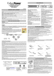
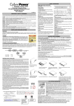
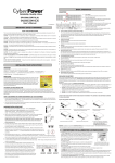
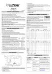
REAR PANEL DESCRIPTION
Professional Tower UPS
PP1500/PP2200
User Manual
◆ Backup Power for Critical Loads
The UPS provides 2 battery powered, surge protected outlets for the most critical connected equipments
and insures temporary uninterrupted operation of connected equipments during a power failure.
K01-P1K50H0-01
NOTE: When the UPS is overloaded, the UPS will interrupt power supply to the other 6 battery
outlets and leave these 2 outlets for critical loads uninterrupted.
SAFETY WARNINGS
◆ Battery Backup and Surge Protection Outlets
This unit provides 6 battery-powered, surge-protected and AVR outlets for connected equipments and
insures uninterrupted operation of connected equipment during a power failure.
(SAVE THESE INSTRUCTIONS)
This manual contains important safety instructions. Please read and follow all instructions carefully during installation and operation of the unit.
Read this manual thoroughly before attempting to unpack, install, or operate your UPS.
This equipment can be operated by any individuals with no previous training.
The socket-outlet shall be installed near the equipment and easily accessible.
During the installation of this equipment it should be assured that the sum of the leakage currents of the UPS and the connected loads does not
exceed 3.5mA.
Attention, hazardous through electric shock. Also with disconnection of this unit from the mains, hazardous voltage still may be accessible
through supply from battery. The battery supply should be therefore disconnected in the plus and minus pole at the quick connectors of the
battery when maintenance or service work inside the UPS is necessary.
Do not dispose of batteries in a fire, the battery may explode.
Do not open or mutilate the battery or batteries, released electrolyte is harmful to the skin and eyes.
◆ Circuit Breaker Reset for Overload Protection
Re-settable circuit breakers provide optimal overload protection.
◆ Communication Protection Ports
Ethernet RJ-45 Network Protection Ports protect your Phone, Fax and Modem from surges over the Ethernet/Phone line.
INSTALLING YOUR UPS SYSTEM
UNPACKING
◆ Serial/ USB Ports
Inspect the UPS upon receipt. The box should contain the following:
UPS Unit x1; PowerPanel Business Edition Software Disk x1; Serial Interface Cable (DB-9) x1; USB Device Cable x1;Telephone Cable x1;
User Manual x1
The PP1500/PP2200 provides two serial and one USB ports to allow connection and communication between the UPS and two computers.
This allows the simultaneous shutdown of two computer systems. These interfaces are also compatible with the UPS service provided by
Windows 2000, Windows NT, Windows XP, Windows Server 2003.
HOW TO DETERMINE THE POWER REQUIREMENTS OF YOUR EQUIPMENT
1. Insure that the equipment plugged into the battery power-supplied outlets does not exceed the UPS unit’s rated capacity (1500VA/1000W for
PP1500, 2200VA/1500W for PP2200). If rated unit capacities are exceeded, an overload condition may occur and cause the UPS unit to
shut down or the circuit breaker to trip.
2. If the power requirements of your equipment are listed in units other than Volt-Amps (VA), convert Watts (W) or Amps (A) into VA by doing
the calculations below. Note: The below equation only calculates the maximum amount of VA that the equipment can use, not what is
typically used by the equipment at any one time. Users should expect usage requirements to be approximately 60% of below value.
1. The Primary PC
To control the UPS and make any change to the operation of the UPS,
please install the PowerPanel Business Editon in your primary computer and
then connect it to the Serial Port I or USB port of the UPS.
TO ESTIMATE POWER REQUIREMENTS
2. The Secondary PC
The secondary computer with PowerPanel installed should be connected to
the serial port II. This PC will shutdown following the user settings in
PowerPanel Software when a power failure occurs but it is unable to exhibit any
control over the UPS.
1.
Watts (W) x 2.0 =
VA or
Amps (A) x 120 =
VA
2. Add the totals up for all pieces of equipment and multiply this total by 0.6 to calculate actual requirements. There are many factors that can
affect the amount of power that your computer system will require. The total load that you will be placing on the battery-powered outlets
should not exceed 80% of the unit’s capacity.
HARDWARE INSTALLATION GUIDE
1. Connect the equipment to your UPS outlets. Items such as copiers, laser printers, vacuums,
space heaters, paper shredders, or other large electrical devices should not be connected to
the UPS. Please assure that the total loads of your equipments must be less than the
maximum total power load of your UPS.
2. Connect your UPS power cord into a two-pole, three-wire grounding receptacle only. Please
avoid using extension cords and adapter plugs. (To maintain optimal battery charge, leave
the UPS plugged in at all times.)
3. Press the UPS power button to turn it on. The “Power On” indicator will be illuminated in
“Green”.
4. Install your optional software and accessories. To use the software, simply connect the enclosed serial interface cable to the serial port on
the UPS and an open serial port on the computer.
BASIC OPERATION
FRONT PANEL DESCRIPTION
◆ Power Switch
Press the ON/OFF button to turn the UPS on or off.
◆ Test Switch
This UPS performs a self-test automatically when power is on. If the UPS passes the test, it
returns to on-line operation. If the UPS fails the self-test, please recharge the battery for 4
hours and perform another self-test. If it fails after recharging the battery, please replace the
battery.
◆ Battery Indicators
BATTERY
CAPACITY
These indicators show a visual indication of the battery charge. If battery capacity is under 20%, no indicator LED will
illuminate and the UPS starts beeping.
◆ Load Level Indicators
LOAD
CAPACITY
Please go to www.cyberpowersystems.com for free download PowerPanel Software.
When power failure occurs, one of the following shutdown sequences will be executed:
1. If the Primary and Secondary serial ports are both in use: the Primary computer will start to count down (user controlled delay) for shutdown
(User Control delay can be set in the PowerPanel Business Edition Recommended time is 5 minutes). Once the Primary computer is shutdown,
the UPS will signal the Secondary computer and initiate the Secondary to shutdown. The UPS default shutdown time is 2 minutes. Therefore,
it is recommended that Secondary computer is set to shutdown within 1 minute in PowerPanel Software.
2. If only the Secondary serial port is in use: the Secondary computer will shutdown following the user settings in PowerPanel Software.
However, the Secondary computer will not able to signal the UPS to shutdown. Therefore, the UPS will only power off when it is in low
battery.
BATTERY REPLACEMENT AND STORAGE
Contact your dealer or call the number in this manual for information on battery replacement.
Read and follow the IMPORTANT SAFETY INSTRUCTIONS before servicing the battery. Service the battery under the supervision of
personnel knowledgeable of batteries and their precautions. Keep unauthorized personnel away from batteries.
CAUTION! Use only the specified type of battery. See your dealer for replacement batteries.
CAUTION! The battery may present the risk of electrical shock. Do not dispose of batteries in a fire, as it may explode. Follow all local
ordinances regarding proper disposal of batteries.
CAUTION! Do not open or mutilate the batteries. Release electrolyte is harmful to the skin and eyes and may be toxic.
CAUTION! A battery can present a high risk of short circuit current and electric shock. Take the following precautions before replacing the
battery:
1. Remove all watches, rings or other metal objects.
2. Only use tools with insulated handles.
3. DO NOT lay tools or other metal parts on top of battery or any battery terminals.
4. Wear rubber gloves and boots.
5. Determine if the battery is inadvertently grounded. If inadvertently grounded, remove source of ground. CONTACT WITH A GROUNDED
BATTERY CAN RESULT IN ELECTRICAL SHOCK! The likelihood of such shock will be reduced if such grounds are removed during
installation and maintenance (applicable to a UPS and a remote battery supply not having a grounded circuit).
BATTERY REPLACEMENT PROCEDURE:
1. Turn off and unplug all connected equipments.
2. Turn the UPS off and unplug it from the AC power source.
3. Carefully turn the UPS upside down. Remove the 6 retaining screws and the
cover.
4. Disconnect the black and red wires from the battery set.
5. Remove the battery protection cover and take out the battery set from the
compartment.
6. Slide a new battery pack into the unit. Assemble the battery protection cover,
cable, screws in the reverse sequence of above steps.
REMINDER: Recharge the unit for 4 – 8 hours to ensure the UPS performs
expected runtime
The UPS does not perform
expected runtime.
The UPS will not turn on.
◆ Using Battery Indicator
This illuminates during utility failure, indicating that the battery is supplying power to the battery-power supplied outlets.
◆ Power On Indicator
This LED is illuminated when the utility condition is normal and the UPS outlets are providing “clean power”, free of surges and
spikes.
(3)
(4)
TROUBLE SHOOTING
Problem
◆ AVR Indicator
This LED indicates that the UPS is operating in automatic voltage regulation mode. When the LED is illuminated continuously,
it indicates input over-voltage and the UPS unit bucks the voltage. When the LED is flashed in rotation, it indicates that the
UPS unit is boosting input voltage.
(2)
STORAGE:
First turn off your UPS and disconnect its power cord from the wall outlet. Disconnect all cables connected to the UPS to avoid battery drain. To
store your UPS for an extended period, cover it and store with the battery fully charged. Recharge the battery every three months to insure
battery life. If the battery remains uncharged for an extended period of time, it may suffer permanent loss of capacity.
These LED indicators show a visual depiction of the UPS load. The load indicator LED will turn orange if the load is
between 80 and 100%. If the load is under 20%, no indicator LED will illuminate.
◆ Wiring Fault Indicator
This LED indicator will illuminate to warn the user that a wiring problem exits with the AC outlet, such as bad ground, miss
ground or reversed wiring. If this is illuminated, the user is advised to disconnect all electrical equipment from the outlet and
have an electrician check the outlet to insure proper wiring.
(1)
Outlets do not provide
power to equipment
Possible Cause
Solution
Batteries are not fully charged.
Recharge the battery by leaving the UPS plugged in.
Battery is slightly worn out.
Contact CyberPower Systems at [email protected].
The on/off switch is designed to
prevent damage by rapidly
turning it off and on.
Turn the UPS off.
Wait 10 seconds and then turn the UPS on.
The unit is not connected to an
AC outlet.
The unit must be connected to a 110/120v 60Hz outlet.
The battery is worn out.
Contact CyberPower Systems at [email protected].
Mechanical problem.
Contact CyberPower Systems at [email protected].
Circuit breaker is tripped due to
overload
Turn the UPS off and unplug at least one piece of equipment. Wait 10
seconds, reset the circuit breaker and then turn the UPS on.
Batteries are discharged
Allow the unit to recharge for at least 4 hours.
Unit has been damaged by a
surge or spike.
Contact CyberPower Systems at [email protected].
PowerPanel Business Edition The serial cable is not
is inactive (all icons are gray). connected.
Connect the serial cable to the UPS unit and an open serial port on the back
of the computer. You must use the cable that came with the unit.
The serial cable is connected to
the wrong port.
Check the back of the computer for an additional serial port.
cable to this port.
The unit is not providing battery
power.
Shutdown your computer and turn the UPS off. Wait 10 seconds and turn the
UPS back on. This should reset the unit.
The serial cable is not the cable
that was provided with the unit.
Move the
You must use the cable that was included with the unit for the software and
the unit to be able to communicate.
Who Pays For Shipping?
We pay when we send items to you; you pay when you send items to us.
TECHNICAL SPECIFICATIONS
Model
PP1500
PP2200
Capacity (VA)
1500VA
2200VA
Capacity (Watts)
1000W
1500W
Input
Input Voltage Range
85Vac – 150Vac
Frequency Range
50/60 Hz +/- 3Hz
Output
On Battery Output Voltage
Pure Sine Wave at 120Vac +/- 7%
On Battery Output Frequency
47-53Hz for 50Hz nominal, 57-63Hz for 60Hz nominal
Transfer Time (Typical)
4ms
Overload Protection
On Utility: Circuit Breaker, On Battery: Internal Current Limiting
Surge Protection and Filtering
Lightning / Surge Protection
Yes
Internet Ready
RJ11/RJ45 (One In/One Out)
(DSL / Phone / FAX / Modem Protection)
(2) NEMA 5-20R
(8) NEMA 5-15R
Dimensions (cm)
25.4
31.1
Battery
Sealed Maintenance Free Lead Acid Battery
12V / 7.0AHx4
Yes
Typical Recharge Time
8 Hours
Warning Diagnostics
Power On, Using Battery, AVR, Wiring Fault, Load Level, Battery Level
Audible Alarms
On Battery, Low Battery, Overload
Environmental
Operating Temperature
+32°F to 95°F ( 0°C to 35°C )
Operating Relative Humidity
0% to 95% Non Condensing
Communication
PowerPanel Business Edition Software
Windows 95/98/ME/NT/2000/XP, Server 2003, Mac OSX, Linux
Management
Self-Test
Manual Self-Test
Auto-Charger/ Auto-Restart/USB
Yes
SNMP/ HTTP Network Card
Optional
DEFINITIONS FOR ILLUMINATED LED INDICATORS
Condition
Power On
AVR
Using
Battery
On
Off
Off
Set
Off
On
Slow flash
Off
Set
Off
AVR- Max. boost 13% of input voltage for output regulation while
input voltage is from 5% to 14% under nominal.
On
Rapid flash
Off
Set
Off
AVR- Max. boost 26% of input voltage for output regulation while
input voltage is from 15% to 29% under nominal.
ON
On
Off
Set
Off
AVR- Max. buck 11% of input voltage for output regulation while
input voltage is from 8% to 25% over nominal.
Off
Off
On
Set
Two Beeps
Off
Off
On
Set
Rapid Beeps
Utility Failure- The UPS is providing battery power. Rapid beeps
indicate the battery will run out of charge within a few minutes.
On/Off
On/ Off
/Flash
On/Off
Set
Long Beep
Overload- Turn the UPS off and unplug at least one piece of
equipment from the UPS. Wait 5 seconds, reset the circuit breaker
and restart the UPS.
Off
Off
On
Up
Long Beep
Overload- Turn the UPS off and unplug at least one piece of
equipment from the UPS. Wait 5 seconds, reset the circuit breaker
and restart the UPS.
Off
Off
Off
Set
Off
Circuit
Breaker
Alarm
Normal
Utility Failure- The UPS is providing battery power to the
Battery-Power Supplied outlets.
Surge Protection Malfunction- Power surge has damaged the unit.
Please contact CyberPower Systems.
Limited Warranty and Connected Equipment Guarantee
Read the following terms and conditions carefully before using the CyberPower UPS (the “Product”). By using the Product you consent to be
bound by and become a party to the terms and conditions of this Limited Warranty and Connected Equipment Guarantee (together referred to
as this “Warranty”). If you do not agree to the terms and conditions of this Warranty, you should return the Product for a full refund prior to using
it.
Who Is Providing This Warranty?
CyberPower Systems (USA), Inc. (“CyberPower”) provides this Limited Warranty.
What Does This Warranty Cover?
This warranty covers defects in materials and workmanship in the Product under normal use and conditions.
connected to the Product and damaged because of the failure of the Product.
It also covers equipment that was
What Is The Period of Coverage?
This warranty covers the Product for three years and connected equipment for as long as you own the Product.
Who Is Covered?
This warranty only covers the original purchaser.
For further information please feel free to contact CyberPower at Cyber Power Systems (USA), Inc. 4241 12th Ave E., STE 400, Shakopee, MN
55379; call us at (877) 297-6937; or send us an e-mail message at [email protected].
FCC Notice
This device complies with part 15 of the FCC Rules. Operation is subject to the following two conditions: (1)This device
may not cause harmful interference, and (2) this device must accept any interference received, including interference
that may cause undesired operation.
12V / 9.0AHx4
Hot Swappable Battery
Indicators
What are the Limitations?
1.
This Warranty does not apply unless the Product and the equipment that was connected to it were connected to properly wired and
grounded outlets (including compliance with electrical and safety codes of the most current electrical code), without the use of any adapters or
other connectors.
2.
The Product must have been plugged directly into the power source and the equipment connected to the Product must be directly
connected to the Product and not “daisy-chained” together in serial fashion with any extension cords, another Product or device similar to the
Product, surge suppressor, or power tap. Any such installation voids the Limited Warranty.
3.
The Product and equipment connected to it must have been used properly in a suitable and proper environment and in conformance
with any license, instruction manual, or warnings provided with the Product and the equipment connected to it.
4.
The Product must have been used at all times within the limitations on the Product’s VA capacity.
(6) NEMA 5-15R
42.0*18.0*23.5
Weight (kg)
1.
This Warranty does not cover any software that was damaged or needs to be replaced due to the failure of the Product or any data that
is lost as a result of the failure or the restoration of data or records, or the reinstallation of software.
2.
This Warranty does not cover or apply to: misuse, modification, operation or storage outside environmental limits of the Product or the
equipment connected to it, nor for damage while in transit or in storage, nor if there has been improper operation or maintenance, or use with
items not designed or intended for use with the Product, such as laser printers, appliances, aquariums, medical or life support devices, etc.
Where Can I Get More Information?
Physical
Total # of UPS Receptacles
What Are Some Things This Warranty Does Not Cover?
Coverage ends if you sell or otherwise transfer the Product.
How Do You Get Service?
1.
Call us at (877) 297-6937 or write to us at Cyber Power Systems (USA), Inc., 4241 12th Ave. E., STE 400, Shakopee, MN 55379 or
send us an e-mail message at [email protected] for instructions.
2.
When you contact CyberPower, identify the Product, the Purchase Date, and the item(s) of Connected Equipment. Have information
on all applicable insurance or other resources of recovery/payment that are available to the Initial Customer and Request a Claim Number.
3.
You must provide a purchase receipt (or other proof of the original purchase) and provide a description of the defect.
4.
Pack and ship the product to CyberPower and, if requested, the item(s) of Connected Equipment, a repair cost estimate for the
damage to the Connected Equipment, and all claim forms that CyberPower provides to you. Show the Claim Number on the shipping label or
include it with the product. You must prepay all shipping costs, you are responsible for packaging and shipment, and you must pay the cost of
the repair estimate.
How Long Do I Have To Make A Claim?
All claims must be made within ten days of the occurrence.
What Will We Do To Correct Problems?
CyberPower will inspect and examine the Product.
If the Product is defective in material or workmanship, CyberPower will repair or replace it at CyberPower's expense, or, if CyberPower is unable
to or decides not to repair or replace the Product (if defective) within a reasonable time, CyberPower will refund to you the full purchase price
you paid for the Product (purchase receipt showing price paid is required).
If it appears that our Product failed to protect any equipment plugged into it, we will also send you forms for making your claim for the connected
equipment. We will repair or replace the equipment that was damaged because of the failure of our Product or pay you the fair market value
(NOT REPLACEMENT COST) of the equipment at of the time of the damage. We will use Orion Blue Book, or another a third-party valuation
guide, or eBay, craigslist, or other source to establish that amount. Our liability is limited to the Connected Equipment Guarantee amount as
stated in the Technical Specifications section.
WARNING!! This equipment has been tested and found to comply with the limits for a Class B Digital Device, pursuant to Part 15 of the FCC
Rules. These limits are designed to provide reasonable protection against harmful interference in residential installation. This equipment
generates, uses and can radiate radio frequency energy and, if not installed and used in accordance with the instructions, may cause harmful
interference to radio communications. However, there is no guarantee that interference will not occur in a particular installation. If this
equipment does cause harmful interference to radio or television reception, which can be determined by turning the equipment off and on, the
user is encouraged to try to correct the interference by one or more of the following measures: (1) Reorient or relocate the receiving antenna.
(2) Increase the separation between the equipment and receiver. (3) Connect the equipment into an outlet on a circuit different from that to
which the receiver is connected.
(4) Consult the dealer or an experienced radio/TV technician for help. Any special accessories needed for
compliance must be specified in the instruction.
The Class B digital apparatus meets all requirements of the Canadian Interference-Causing Equipment Regulation.
Cet appareil numerique de la class B respecte toutes les exigencies du Reglement sur le materiel brouilleur du Canada