1
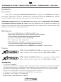
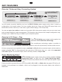
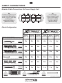
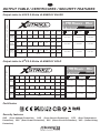
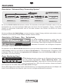
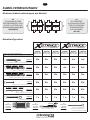
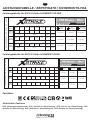
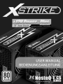
1
HI-ENERGY silver
HI-ENERGY gold
MANUFACTURER INFORMATION
HERSTELLERINFORMATIONEN
ELVT Europe
Liebigstraße 2 - 20
22113 Hamburg
GERMANY
WWW
EMAIL
www.nesteq.net
[email protected]
2
CONTENT - INHALTSVERZEICHNIS
ENGLISH
Introduction / Main features / Versions / Accessories
3
Key features
4
Cable connections
5
Output table / Certificates / Security features
6
Installation
7
Troubleshooting / Warranty and RMA
8
DEUTSCH
Einleitung / Haupt-Features / Versionen / Zubehör
9
Features
10
Kabelverbindungen
11
Leistungstabelle / Zertifikate / Sicherheits-Features
12
Einbau des Netzteils
13
Fehlerbehebung / Garantie und RMA-Abwicklung
14
Caution! Life-threatening situation! Never
open the housing of the power supply!
Power supply units are maintenance-free
components that should be opened by
specially trained professionals only. If you
open the power supply housing by yourself,
your warranty will automatically expire.
Achtung! Öffnen Sie das Gehäuse des
Netzteils nicht! Es besteht Lebensgefahr!
Netzteile sind wartungsfrei und dürfen nur von
Fachpersonal geöffnet werden. Wenn Sie Ihr
Netzteilgehäuse selber öffnen sollten, erlischt
automatisch
auch
Ihr
Anspruch
auf
Garantieleistungen.
Components within a power supply unit may
retain high voltages, that are life-threatening,
even after switching it off and pulling the
plug. If you should observe development of
smoke or changes of the housing that are not
self-inflicted, pull the plug of the power
supply immediately. Do not use the power
supply again!
Bauteile im Netzteil stehen selbst nach dem
Ausschalten und Trennen vom Stromnetz noch
einige Zeit unter Hochspannung und können zu
lebensgefährlichen Verletzungen führen. Falls
Sie Rauchentwicklung oder nicht selbständig
verursachte Veränderungen am Gehäuse
feststellen sollten, ziehen Sie den Netzstecker
und verwenden Sie das Netzteil nicht weiter!
If you have any questions, please consult
your retailer, or send us an email to:
[email protected]
Wenden Sie sich bei allen Fragen an Ihren
Fachhändler oder schreiben Sie uns eine Email:
[email protected]
3
INTRODUCTION / MAIN FEATURES / VERSIONS / ACCES.
Introduction
Dear Customer,
Thank you for purchasing a NesteQ E2CS X-Strike power supply unit. All NesteQ power supplies
are expertly engineered in Germany. Assembled with high-quality components, NesteQ power supplies
series guarantee outstanding power performance for your computer system.
E2CS power supplies passed the strict 80 PLUS testing program, and are rated at least 80% efficiency.
The maximum efficiency reaches up to 88%, which can effectively lower the power consumption, the
expense for your power bill, and the overall temperature inside your computer case. Last but not least, high
efficiency is favorable to environment protection.
Main features
• Conforms to ATX Version 2.2 / EPS 2.91 / BTX 1.0a
• High quality components for ultimate reliability and performance
• Patented EECS - Enhanced Easy Connecting System
• Patented “+12V Power - Plus” technology
• DIY - cable length and configuration
• High efficiency - up to 88%, conforms to 80 PLUS standard
• Large ultra-quiet 135 mm fan with Hydraumatic bearing
• Compatible with NVIDIA® SLi® and AMD/ATI® CrossFireX™ graphics cards
Versions
E2CS X-Strike HI-ENERGY SILVER power supplies have four +12 volt
rails, and offer a power range as follows: 400W, 500W or 600W.
HI-ENERGY silver
E2CS X-Strike HI-ENERGY GOLD power supplies have six +12 volt
HI-ENERGY gold
rails, and offer a power range as follows: 750W, 850W or 1000W.
Accessories
•
•
•
•
1 x PS-On ATX adaptor:
Connect this adaptor for starting your power supply unit without a mainboard. Connect the adaptor
to the 20+4-pin connector, and press the on/off switch on the power supply unit. The four green
LED lights indicate proper functionality. If one of the lighst should be off, this indicates a power
failure. In this case please consult your retailer for further assistance.
4 x Plug-covers for 6-pin connectors (2x HI-ENERGY silver edition)
4 x Screws • 1 x AC-cable • 10 x Cable ties
Modular cables (see cable chart on page 5)
4
KEY FEATURES
Patented “Enhanced Easy Connecting System”
DO NOT CONNECT MORE
THAN FOUR CABLES
POWER SUPPLY UNIT
EXTENSION CABLE
CONNECTION 1 / 4
PERIPHERAL POWER
CABLE 4-PIN MOLEX
CONNECTION 2 / 4
SERIAL ATA DEVICE
POWER CABLE
CONNECTION 3 / 4
FAN
CONNECTION CABLE
CONNECTION 4 / 4
You will receive a special flexibility only from the E2CS X-Strike power supply series, when it comes to
configuration of the useful cables. You can combine hard drive, floppy and Serial-ATA plugs freely, and
those cables will be used only in real need, it goes without saying, in an unique way.
You can use up to four cables to make one long cable. With other power supply units you can never have
such a dream flexibility in cable management. The illustration above serves as a sample configuration only.
Configure your cables the way you need for your computer system.
Patented +12V Power - Plus
The E2CS X-Strike power supply series applies the
patented +12V Power-Plus technology.
This revolutionary technology makes it possible to
supply the most important computer (mainboard, graphics card) with a particularly resilient power source.
All these components are supplied through a combined +12V rail with an eventual output, which varies by
models, of up to 75A. For the peripherals like hard drives, DVD drives, fans, etc., each of the separated
+12V rails supplies an eventual output, which varies by models, of up to 30A.
Power Monitoring Panel
Power Monitoring Panel
+12V
+5V
+3.3V
+5Vsb
E2CS X-Strike power supply series has an easily readable “Power
Monitoring Panel” on each unit. The “Power Monitoring Panel”
indicates if there are problems with the most important power output
rails.
If there should be a power failure on one of the +12V, +5V, +3.3V or +5Vsb rails, the green LED will be off.
Included in the package is an adaptor, which can be plugged to test the power supply even without a
mainboard.
5
CABLE CONNECTIONS
Modular Cable Connections On Power Supply Unit
4x
POWER CONNECTIONS
4-PIN FOR PERIPHERAL,
SATA, FLOPPY, FAN AND
EXTENSION
MODULAR CABLES
(BLACK COLOR)
1
2
1
2
3
4
3
4
4x
PCI-EXPRESS
8-PIN CONNECTIONS
FOR PCI-EXPRESS
GRAPHICS CARDS
6+2-PIN CABLES
(BLUE COLOR)
Cable Configuration
HI-ENERGY gold
HI-ENERGY silver
MODULAR CABLES OVERVIEW
EECS - ENHANCED EASY CONNECTING SYSTEM
500MM
400W
500W
600W
750W
850W
1000W
MODEL NO.:
ECS XS-400
MODEL NO.:
ECS XS-500
MODEL NO.:
ECS XS-600
MODEL NO.:
ECS XS-750
MODEL NO.:
ECS XS-850
MODEL NO.:
ECS XS-1000
2x
2x
2x
4x
4x
4x
2x
2x
2x
4x
4x
5x
2x
2x
2x
3x
3x
3x
2x
2x
2x
2x
2x
2x
2x
2x
2x
2x
2x
2x
1x
1x
1x
1x
1x
2x
PCI-EXPRESS GRAPHICS CONNECTOR 6/8-PIN
250MM 150MM 50MM
450MM
SERIAL ATA DEVICE POWER CABLE
250MM 150MM 50MM
450MM
PERIPHERAL POWER CABLE 4-PIN MOLEX
50MM
FLOPPY DISK DRIVE CONNECTOR 4-PIN
510MM 70MM
70MM
650MM
FAN CONNECTION CABLE
400MM
EXTENSION CABLE
1x
TOTAL
LENGTH:
600MM
20/24-PIN ATX CABLE
1x
TOTAL
LENGTH:
600MM
100MM
4/8-PIN P4/EPS CABLE
1x
TOTAL
LENGTH:
500MM
FAN RPM MONITORING CABLE
NON-MODULAR CABLES
6
OUTPUT TABLE / CERTIFICATES / SECURITY FEATURES
AC INPUT: 100 - 240V / 60 - 50Hz
Output table for E2CS X-Strike HI-ENERGY SILVER
HI-ENERGY silver
DC
OUTPUT +3.3V
400W
20A
MODEL NO.:
ECS XS-400
500W
+12V1 +12V2 +12V3 +12V4
20A
18A
130W
25A
MODEL NO.:
ECS XS-500
600W
+5V
25A
25A
18A
18A
360W
22A
150W
MODEL NO.:
ECS XS-600
18A
22A
22A
22A
432W
25A
25A
150W
25A
25A
25A
504W
-12V
+5VSB
0.3A
3.0A
3.6W
15.0W
0.3A
3.0A
3.6W
15.0W
0.3A
3.0A
3.6W
15.0W
EPS
8 PIN
P4
4 PIN
PCI EXP.
6+2 PIN
+12V/24A
+12V/24A
+12V/24A
+12V/30A
+12V/30A
+12V/30A
+12V/35A
+12V/35A
+12V/40A
AC INPUT: 100 - 240V / 60 - 50Hz
Output table for E2CS X-Strike HI-ENERGY GOLD
HI-ENERGY gold
DC
OUTPUT +3.3V
750W
25A
MODEL NO.:
ECS XS-750
850W
25A
+12V1 +12V2 +12V3 +12V4 +12V5 +12V6
20A
20A
150W
28A
MODEL NO.:
ECS XS-850
1000W
+5V
30A
28A
30A
180W
25A
25A
25A
600W
25A
25A
180W
MODEL NO.:
ECS XS-1000
25A
25A
25A
20A
20A
700W
30A
30A
30A
30A
900W
30A
30A
-12V
+5VSB
0.3A
6.0A
3.6W
30.0W
0.8A
6.0A
9.6W
30.0W
0.8A
6.0A
9.6W
30.0W
EPS
8 PIN
P4
4 PIN
PCI EXP.
6+2 PIN
+12V/40A
+12V/40A
+12V/45A
+12V/45A
+12V/45A
+12V/58A
+12V/45A
+12V/45A
+12V/75A
Certificates
RoHS
C O M P L I A N T
Security features
OVP (Over-Voltage-Protection), OCP (Over-Current-Protection), OTP (Over-TemperatureProtection), OPP (Over-Power-Protection), SCP (Short-Circuit-Protection), UVP (Under-Voltag
Protection)
7
INSTALLATION
Note: You need a crosshead screwdriver to install or remove the power
supply unit. When working on your computer, make sure that you have
enough space, time and a well lit place. Do not rush, and do not use excessive force to remove, plug or unplug anything.
To remove the power supply unit from your case
1.
Turn off your system, and unplug the AC power cable from your power supply.
This is the main power cable plugged into a wall outlet and connected to the power supply unit.
2.
Disconnect all other cables (e.g. screen, USB, audio cables, etc.) that are connected to
your computer. Consult the user manual of your computer case, and open it accordingly.
3.
Disconnect all power supply cables, that are are connected to the mainboard (20/24-pin, P4, EPS,
etc.) and components (graphics card(s), HDD, DVD drive, etc.). Double-check that all cables have
been properly disconnected.
4.
While holding the power supply unit in place with one hand, you can now remove the four screws
securing it to your case. Carefully take the power supply unit out of the PC case. Make sure that no
cable is caught up or tangled.
To install the power supply unit in your case
1.
Place the power supply unit into the computer case, and secure it with the four screws.
2.
Locate the ATX connector on your mainboard. Consult the user manual of your mainboard, if you
have problems locating the connector. Carefully guide the 20+4-pin ATX connector through the
case, and connect it to your mainboard.
3.
Connect the P4 4-pin or EPS 8-pin power cable to the mainboard. Consult the user manual of your
mainboard to figure out the proper ways of necessary connections for the mainboard.
4.
Connect the 6+2-pin cable to the PCI-Express graphics cards installed in your system. Consult the
graphics card’s user manual to figure out the proper ways of the necessary connections. You will
need 2 connectors with either 6 or 8 pins for modern graphics cards.
5.
Connect all 4-pin Molex and SATA connectors to your hard drives and optical drives, and then
connect other internal components to correspondent connectors (e.g. case fans, lighting, etc.).
6.
Connect the 3-pin fan monitoring cable to the appropriate connector on your mainboard. Usually
this 3-pin port is marked with “PSU FAN” or “POWER FAN”. Consult your mainboard’s user manual
to find the right connector. If your mainboard does not offer this option, you may also use a “CASE
FAN” connector.
7.
Replace the computer case cover as instructed in the user manual. Connect at least the
keyboard, the mouse and the screen, and plug the main power cable into the power supply unit.
Switch on the power supply unit, and then turn on your system by pressing the power button on
your case. If your computer does not turn on, repeat the previous steps, or turn to the following
page for troubleshooting instructions.
8
TROUBLESHOOTING / WARRANTY AND RMA
Note: If you are not familiar with the steps taken, please consult a professional. Should you notice that your power supply is developing smoke or
has any broken cables, or is exposed to liquids, unplug it immediately, and
do not turn it on again. Consult a professional for further assistance.
Troubleshooting
If you experience any problems with your power supply unit, please read the following information, or
consult your retailer, where you purchased the unit. Alternatively you can send an email directly to NesteQ
at [email protected]. Please specify your configuration and the problems you encountered.
•
Double-check if the main power plug is connected properly to the power supply as well as the
wall outlet. Verify, if the wall outlet is functions well while connected with other electric appliances.
•
Double-check if all connections from the power supply are correctly plugged into the mainboard
as well as other components. Also check if all modular cables are connected properly to the power
supply unit.
•
The power button (PS-ON) on the computer case should be connected directly to the mainboard.
Consult the user manual of the case and the mainboard respectively to confirm the right ways for
connection.
•
To rule out defective hardware, firstly connect only the mainboard and the graphics card with
the power supply unit, and unplug data cables from hard drives and optical devices. If the
computer turns on with this minimal configuration, try to connect one more component at a time to
find out which one is defective or may cause compatibility issues.
Warranty and RMA
All power supply units from NesteQ have a 3-year warranty period. The warranty is applicable for all
technical parts of the power supply. NesteQ will undertake the task to check, repair or exchange the
defective power supply during the 3-year warranty period.
To claim your warranty, please keep the official receipt, and consult the retailer, where you bought the
product.
9
EINLEITUNG / HAUPT-FEATURES / VERSIONEN / ZUBEH.
Einleitung
Sehr geehrter Kunde,
vielen Dank für den Kauf eines NesteQ E2CS X-Strike Netzteils. NesteQ ist Hersteller von
Hochleistungs-Netzteilen, die fachmännisch in Deutschland entwickelt wurden. Durch Verwendung von
qualitativ hochwertigen Komponenten, erhalten Sie stets herausragende Leistung für den Strombedarf
Ihres Computers.
Netzteile der E2CS Serie haben die strengen Tests des 80 PLUS Programms bestanden und bieten
dadurch eine Effizienz von mindestens 80%. Maximal erzielt das Netzteil eine Effizienz von bis zu
88%. Dies sorgt nicht nur für einen geringeren Stromverbrauch, sondern auch für eine niedrigere Stromrechnung. Eine hohe Effizienz wirkt sich zudem positiv auf die Temperatur in Ihrem Computergehäuse aus.
Nicht zuletzt trägt eine hohe Effizienz zum Schutz wertvoller Umweltressourcen bei.
Haupt-Features
• ATX Version 2.2 / EPS 2.91 / BTX 1.0a konform
• Beste Komponenten sorgen für Zuverlässigkeit und höchste Leistung
• Patentiertes EECS - Enhanced Easy Connecting System
• Patentierte “+12V Power - Plus” Technologie
• Kabellängen und Konfiguration lassen sich individuell anpassen
• Hohe Effizienz - bis zu 88%, erfüllt 80 PLUS Norm
• Großer ultra-leiser 135mm Lüfter mit Hydraumatic-Lager
• Kompatibel zu NVIDIA® SLi® und AMD/ATI® CrossFireX™ Grafikkarten-Konfigurationen
Versionen
E2CS X-Strike HI-ENERGY SILVER Netzteile verfügen über vier +12
Volt Leitungen. X-STRIKE HI-ENERGY SILVER Netzteile haben eine
HI-ENERGY silver
Ausgangsleistung von entweder 400W, 500W oder 600W.
E2CS X-Strike HI-ENERGY GOLD Netzteile verfügen über sechs +12
Volt Leitungen. X-STRIKE HI-ENERGY GOLD Netzteile haben eine
HI-ENERGY gold
Ausgangsleistung von entweder 750W, 850W oder 1000W.
Zubehör
• 1 x PS-On ATX Adapter:
Verbinden sie den Adapter mit dem Netzteil, um das Netzteil auch ohne Mainboard anschalten zu
können. Schließen Sie den Adapter direkt an den 20+4-Pin Anschluss an und drücken Sie den
An-/Aus-Schalter am Netzteil. Die grünen Lichter am Netzteil dienen als Hinweis, dass das Netzteil
ordnungsgemäß funktioniert. Sollte ein Licht nicht grün aufleuchten, deutet dies auf einen Defekt hin.
In diesem Fall kontaktieren Sie Ihren Händler für die weitere Vorgehensweise.
• 4 x Anschluss-Abdeckungen für die 6-Pin Stecker (2x HI-ENERGY SILVER EDITION)
• 4 x Schrauben • 1 x AC-Stromkabel • 10 x Kabelbinder
• Modulare Kabel (siehe Seite 11 für das Kabeldiagramm)
10
FEATURES
Patentiertes “Enhanced Easy Connecting System”
VERBINDEN SIE NICHT
MEHR ALS VIER KABEL
NETZTEIL
VERLÄNGERUNGS KABEL
VERBINDUNG 1 / 4
PERIPHERIE STROMKABEL 4-PIN MOLEX
SERIAL ATA GERÄTE
STROMKABEL
VERBINDUNG 2 / 4
VERBINDUNG 3 / 4
LÜFTER
VERBINDUNGSKABEL
VERBINDUNG 4 / 4
Nur bei der E2CS X-Strike Netzteilserie erhalten Sie besonders komfortable Flexibilität, wenn es um die
Konfiguration der von Ihnen benötigten Kabel geht. So können Sie die Festplatten-, Floppy-, Serial-ATAStecker frei miteinander kombinieren und nur die Kabel kommen zum Einsatz, die wirklich von Ihnen
benötigt werden.
Sie können bis zu vier Kabelstränge zu einem einzelnen, langen Strang verbinden und erhalten so eine
Flexibilität, wie Sie es bei keinem anderen Netzteil erhalten werden.
Patentierte +12V Power - Plus - Technologie
Die E2CS X-Strike Netzteilserie verfügt über die
patentierte +12V Power-Plus Technologie. Diese
revolutionäre Technologie ermöglicht eine besonders
belastbare Stromzufuhr der wichtigsten Komponenten heutiger Computer (Mainboard, Grafikkarte).
Die Netzteile aus der E2CS X-Strike Netzteilserie versorgen diese Komponenten mit einer kombinierten
+12V Leitung, welche je nach Modell mit bis zu 75A belastbar ist. Peripheriegeräte (Festplatten, DVD
Laufwerke, Lüfter etc.) werden durch getrennte +12V Leitungen, die je nach Modell bis zu 30A zur Verfügung stellen, mit Strom versorgt.
Power Monitoring Panel
E2CS X-Strike Netzteile verfügen an der Rückseite über das innovative und einfach abzulesende “Power Monitoring Panel”. Das
“Power Monitoring Panel” zeigt mögliche Probleme bei den wichtig+12V
+5V
+3.3V +5Vsb
sten Stromleitungen an. LEDs, die nicht leuchten, dienen als Hinweis
auf Probleme bei den +12V, +5V, +3.3V oder +5Vsb Leitungen.
Power Monitoring Panel
Grüne LEDs zeigen die korrekte Funktion des Netzteiles an. Im Lieferumfang befindet sich ein Adapter, der
einen Funktionalitätstest des Netzteils sogar ohne ein verfügbares Mainboard ermöglicht.
11
KABELVERBINDUNGEN
Modulare Kabelverbindungen am Netzteil
4x
4-PIN ANSCHLÜSSE
FÜR PERIPHERIE, SATA,
FLOPPY, LÜFTER UND
VERLÄNGERUNGSKABEL
(SCHWARZ)
1
2
1
2
3
4
3
4
4x
PCI-EXPRESS
8-PIN ANSCHLÜSSE
FÜR PCI-EXPRESS
GRAFIKKARTEN
6+2-PIN KABEL
(BLAU)
Kabelkonfiguration
HI-ENERGY gold
HI-ENERGY silver
MODULARE KABEL ÜBERSICHT
EECS - ENHANCED EASY CONNECTING SYSTEM
500MM
400W
500W
600W
750W
850W
1000W
MODEL NO.:
ECS XS-400
MODEL NO.:
ECS XS-500
MODEL NO.:
ECS XS-600
MODEL NO.:
ECS XS-750
MODEL NO.:
ECS XS-850
MODEL NO.:
ECS XS-1000
2x
2x
2x
4x
4x
4x
2x
2x
2x
4x
4x
5x
2x
2x
2x
3x
3x
3x
2x
2x
2x
2x
2x
2x
2x
2x
2x
2x
2x
2x
1x
1x
1x
1x
1x
2x
PCI-EXPRESS GRAFIX ANSCHLÜSSE 6/8-PIN
250MM 150MM 50MM
450MM
SERIAL ATA GERÄTE STROMKABEL
250MM 150MM 50MM
450MM
PERIPHERIE STROMKABEL 4-PIN MOLEX
50MM
FLOPPY DISK ANSCHLÜSSE 4-PIN
510MM 70MM
70MM
650MM
LÜFTER VERBINDUNGSKABEL
400MM
VERLÄNGERUNGSKABEL
1x
GESAMTLÄNGE:
600MM
20/24-PIN ATX KABEL
1x
GESAMTLÄNGE:
600MM
100MM
4/8-PIN P4/EPS KABEL
1x
GESAMTLÄNGE:
500MM
LÜFTER-UNDREHUNG
ÜBERWACHUNGSKABEL
NICHT-MODULARE KABEL
12
LEISTUNGSTABELLE / ZERTIFIKATE / SICHERHEITS-FEA.
AC EINGANGSSP.: 100 - 240V / 60 - 50Hz
Leistungstabelle für E2CS X-Strike HI-ENERGY SILVER
HI-ENERGY silver
DC AUSGANG +3.3V
400W
20A
MODEL NO.:
ECS XS-400
500W
+12V1 +12V2 +12V3 +12V4
20A
18A
130W
25A
MODEL NO.:
ECS XS-500
600W
+5V
25A
25A
18A
18A
360W
22A
150W
MODEL NO.:
ECS XS-600
18A
22A
22A
22A
432W
25A
25A
150W
25A
25A
25A
504W
-12V
+5VSB
0.3A
3.0A
3.6W
15.0W
0.3A
3.0A
3.6W
15.0W
0.3A
3.0A
3.6W
15.0W
EPS
8 PIN
P4
4 PIN
PCI EXP.
6+2 PIN
+12V/24A
+12V/24A
+12V/24A
+12V/30A
+12V/30A
+12V/30A
+12V/35A
+12V/35A
+12V/40A
AC EINGANGSSP.: 100 - 240V / 60 - 50Hz
Leistungstabelle für E2CS X-Strike HI-ENERGY GOLD
HI-ENERGY gold
DC AUSGANG +3.3V
750W
MODEL NO.:
ECS XS-750
850W
MODEL NO.:
ECS XS-850
1000W
MODEL NO.:
ECS XS-1000
25A
+5V
25A
+12V1 +12V2 +12V3 +12V4 +12V5 +12V6
20A
20A
150W
28A
30A
30A
25A
25A
25A
600W
25A
25A
180W
28A
25A
25A
25A
20A
20A
700W
30A
180W
30A
30A
30A
900W
30A
30A
-12V
+5VSB
0.3A
6.0A
3.6W
30.0W
0.8A
6.0A
9.6W
30.0W
0.8A
6.0A
9.6W
30.0W
EPS
8 PIN
P4
4 PIN
PCI EXP.
6+2 PIN
+12V/40A
+12V/40A
+12V/45A
+12V/45A
+12V/45A
+12V/58A
+12V/45A
+12V/45A
+12V/75A
Zertifikate
RoHS
C O M P L I A N T
Sicherheits-Features
OVP (Überspannungsschutz), OCP (Schutz vor Überlastung), OTP (Schutz vor Überhitzung), OPP
(Schutz vor Überlastung), SCP (Schutz vor Kurzschlüssen), UVP (Schutz vor Unterspannung)
13
EINBAU DES NETZTEILS
Anmerkung: Für den Ein-/Ausbau eines Netzteiles benötigen Sie einen KreuzschlitzSchraubendreher. Wenn Sie an Ihrem Computer arbeiten, sorgen Sie für genügend
Platz, Zeit und einen gut beleuchteten Arbeitsplatz. Übereilen Sie nichts und verwenden
Sie nie zu viel Kraft, um etwas zu entfernen, einzustecken oder herauszuziehen.
Ausbau eines Netzteiles aus Ihrem Gehäuse
1.
Schalten Sie Ihren Computer aus und ziehen Sie das Stromkabel aus Ihrem Netzteil. Dies ist das
Hauptkabel welches mit der Wandsteckdose und dem Netzteil verbunden ist.
2.
Ziehen Sie alle anderen Kabel (z.B. Bildschirm-, USB-, Audio-Kabel, etc.), die mit dem Computer
verbunden sind, heraus. Schauen Sie in der Bedienungsanleitung des Gehäuses nach, wie Sie es
öffnen können und verfahren Sie wie beschrieben.
3.
Innerhalb Ihres Gehäuses ziehen Sie nun alle Kabel des Netzteils, die mit dem Mainboard
(20/24-Pin, P4, EPS, etc.), sowie den Komponenten (Grafikkarte, HDD, DVD Laufwerke, etc.)
verbunden sind, heraus. Kontrollieren Sie, dass alle Kabel ordnungsgemäß herausgezogen
wurden.
4.
Während Sie das Netzteil mit einer Hand festhalten, können Sie nun die vier Schrauben, die das
Netzteil in Position halten, herausdrehen. Entfernen Sie das Netzteil vorsichtig aus dem Gehäuse.
Achten Sie darauf, dass sich keine Kabel an Gehäusekanten und Erweiterungskarten verfangen.
Einbau eines Netzteiles in Ihrem Gehäuse
1.
Platzieren Sie das Netzteil an dem vorgesehen Ort im Gehäuse und befestigen Sie es mit den vier
Schrauben.
2.
Lokalisieren Sie den ATX Anschluss auf dem Mainboard. Ziehen Sie die Bedienungsanleitung des
Mainboards zu rate, falls Sie Probleme haben den Anschluss zu finden. Leiten Sie das Kabel
vorsichtig durch das Gehäuse und verbinden Sie es.
3.
Verbinden Sie das 4-Pin P4 oder das 8-Pin EPS Kabel mit dem Anschluss am Mainboard. Schauen
Sie in der Bedienungsanleitung des Mainboards nach, welche Verbindungen benötigt werden.
4.
Verbinden Sie nun das 6+2-Pin Kabel mit der(n) Grafikkarte(n). Ziehen Sie hierfür die
Bedienungsanleitung der Grafikkarte zu rate, um festzustellen, welche Art von Verbindung(en)
benötigt werden. Moderne Grafikkarten müssen mit bis zu zwei Stromverbindungen, mit 6- oder
8-Pin Anschluss, versorgt werden.
5.
Verbinden Sie alle 4-Pin Molex und SATA Kabel mit Ihren Festplatten und optischen Laufwerken.
Verbinden Sie auch alle weiteren internen Komponenten mit den dafür vorgesehenen Kabeln
(z.B. Lüfter, Beleuchtung, etc.)
6.
Verbinden Sie das 3-Pin Drehzahlüberwachungskabel mit dem passenden Anschluss des
Mainboards. Gewöhnlich wird der 3-Pin Anschluss durch “PSU FAN” oder “POWER FAN”
gekennzeichnet. Die Bedienungsanleitung des Mainboards sollte den korrekten Anschluss
ausweisen. Falls das Mainboard über keinen solchen Anschluss verfügt, verwenden Sie einen
“CASE FAN” Anschluss.
7.
Schließen Sie, wie in der Bedienungsanleitung des Gehäuses beschrieben, das Gehäuse.
Verbinden Sie mindestens die Tastatur, die Maus und den Bildschirm mit dem Computer. Stecken
Sie das Hauptstromkabel in das Netzteil und in eine geeignete Wandsteckdose. Schalten Sie das
Netzteil ein und drücken Sie den Schalter am Gehäuse. Falls Ihr Computer nicht reagiert,
wiederholen Sie die vorherigen Schritte und lesen Sie den Abschnitt zur Fehlerbehebung.
14
FEHLERBEHEBUNG / GARANTIE UND RMA-ABWICKLUNG
Anmerkung: Falls Sie mit den durchzuführenden Schritten nicht vertraut sein sollten,
wenden Sie sich bitte an einen Fachmann. Sollten Sie Rauchentwicklung, beschädigte
Kabel oder Flüssigkeitsschäden feststellen, trennen Sie das Netzteil vom Stromnetz
und verwenden es nicht weiter. Wenden Sie sich in diesem Fall an einen Fachmann.
Fehlerbehebung
Falls Sie Probleme mit dem Netzteil haben sollten, lesen Sie bitte die folgenden Informationen oder
wenden Sie sich an Ihren Händler, bei dem Sie das Netzteil erworben haben. Alternativ können Sie auch
an NesteQ direkt eine Email senden: [email protected]. Bitte spezifizieren Sie Ihre Konfiguration und
das Problem so genau wie möglich.
•
Kontrollieren Sie, dass das Hauptstromkabel korrekt mit dem Netzteil und der Wandsteckdose
verbunden wurde. Stellen Sie sicher, dass die Wandsteckdose funktioniert, indem Sie ein anderes
Gerät zur Prüfung anschließen.
•
Kontrollieren Sie, dass alle Verbindungen vom Netzteil zum Mainboard und den Komponenten
richtig angeschlossen sind. Kontrollieren Sie auch, dass die modularen Kabel am Netzteil korrekt
angeschlossen wurden.
•
Der Anschluss vom Hauptschalter (PW-ON) bei Computergehäusen muss mit dem Mainboard
direkt verbunden werden. Schauen Sie in der Bedienungsanleitung des Gehäuses und des
Mainboards nach, welches Kabel an welchen Pins des Mainboards angeschlossen werden muss.
•
Um defekte Hardware als Ursache auszuschließen, versuchen Sie lediglich das Mainboard und die
Grafikkarte mit dem Netzteil zu verbinden. Entfernen Sie auch alle Datenkabel zu Festplatten und
optischen Laufwerken. Falls der Computer in dieser minimalen Konfiguration funktioniert, verbinden
sie jeweils eine weitere Komponente im ausgeschalteten Zustand, um herauszufinden welches
Gerät defekt oder inkompatibel ist.
Garantie und RMA-Abwicklung
Alle Netzteile von NesteQ haben eine erweiterte Garantie von 3 Jahren. Die Garantie umfasst alle
technischen Bauteile des Netzteils. Sollte es Grund zur Beanstandung geben im Bezug auf die technischen Eigenschaften eines NesteQ Netzteils, übernimmt NesteQ die Überprüfung, Reparatur oder
Austausch des betroffenen Netzteils innerhalb der 3 jährigen Gewährleistungsfrist ab Kaufdatum.
Um von den Garantieleistungen Gebrauch zu machen, heben Sie den Kaufbeleg des Netzteils auf und
wenden Sie sich an den Händler, bei dem Sie das Netzteil erworben haben.