1
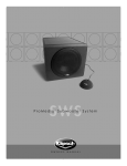
SUBWOOFER
IMPORTANT SAFETY INSTRUCTIONS
1. READ these instructions.
2. KEEP these instructions.
3. HEED all warnings.
4. FOLLOW all instructions.
5. DO NOT use this apparatus near water.
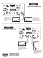
Conventional Speaker Wire Connections – Using 16-gauge or larger speaker wire, connect the
RED “positive” (+) terminal of your amplifier’s LEFT channel to the RED (+) terminal of your
subwoofer’s LEFT channel input (“HIGH LEVEL IN”). Connect the BLACK “negative” (-) terminal of
your amplifier’s LEFT channel to the BLACK “negative” (-) terminal of your subwoofer’s LEFT
channel input (“HIGH LEVEL IN”). Repeat this procedure for connecting your amplifier’s RIGHT
channel to your subwoofer’s RIGHT channel input (refer to Figure 4). Take care to make sure that
no bare wires from any of the connections touch any other terminals as this could cause a short
and damage your equipment.
6. CLEAN ONLY with dry cloth.
7. DO NOT block any ventilation openings. Install in accordance with the manufacturer's instructions.
8. DO NOT install near any heat sources such as radiators, heat registers, stoves, or other
apparatus (including amplifiers) that produce heat.
9. DO NOT defeat the safety purpose of the polarized or grounding type plug. A polarized plug has two
blades with one wider than the other. A grounding type plug has two blades and a third grounding
prong. The wider blade or the third prong are provided for your safety. If the provided plug does not fit
into your outlet, consult an electrician for replacement of the obsolete outlet.
10. PROTECT the power cord from being walked on or pinched, particularly at plugs, convenience
receptacles, and the point where it exits from the apparatus.
“HIGH LEVEL OUT” – This passes the “HIGH LEVEL IN” signal out to your left and right speakers
with frequencies below 100Hz removed.
“LINE IN/LFE” – This input is filtered by the built-in “LOW PASS” (LP) crossover and is designed as
a general purpose input for the subwoofer. It accepts the LFE signal output of your digital
surround electronics.
“LOW PASS” (LP) CROSSOVER – The crossover allows the user to select the upper-frequency
cutoff of the subwoofer. The frequency is selectable from 40-120Hz. Frequencies above the set
level are filtered out, allowing you to blend the subwoofer’s output with that of your main speakers.
11. ONLY USE attachments/accessories specified by the manufacturer.
12. USE only with a cart, stand, tripod, bracket, or table specified by the manufacturer, or sold with the
apparatus. When a cart is used, use caution when moving the cart/apparatus combination to
avoid injury from tip-over.
13. UNPLUG this apparatus during lightning storms or when unused for long periods of time.
14. REFER all servicing to qualified service personnel. Servicing is required when the apparatus has
been damaged in any way, such as power-supply cord or plug is damaged, liquid has been spilled
or objects have fallen into the apparatus, the apparatus has been exposed to rain or moisture, does
not operate normally, or has been dropped.
This symbol indicates that there are important operating and maintenance instructions in the
literature accompanying this unit.
This symbol indicates that dangerous voltage constituting a risk of electric shock is present
within this unit.
WARNING: To reduce the risk of fire or electrical shock, do not expose this apparatus to rain or
moisture. The product must not be exposed to dripping and splashing and no object filled with fluids –
such as a vase of flowers – should be placed on the product.
RISK OF ELECTRIC SHOCK
DO NOT OPEN
WARNING: Voltages in this equipment are hazardous to life. There are no user-serviceable parts inside.
Refer all servicing to qualified service personnel.
CAUTION: Changes or modifications not expressly approved by the manufacturer could void the users
authority to operate this device.
“GAIN” – This control serves as an overall volume control for the subwoofer. It is used to match the
output level of the subwoofer to the main speakers.
“PHASE” 0/180 – This control is used to acoustically match the subwoofer’s output to your main
speakers. Select the position, either 0˚ or 180˚, in which your subwoofer has more output at the
listening position.
“POWER” ON/OFF– In the “ON” position, the subwoofer will remain “on” constantly or can turn
“on” and “off” automatically when the “AUTO/ON” circuit is engaged (see “AUTO/ON”). In the
“OFF” position, the subwoofer will remain “off” until the switch is manually turned back to the
“ON” position.
AUTO/ON – When the main “POWER” ON/OFF switch is in the “OFF” position, this switch has no
affect on the subwoofer. When the main “POWER ON/OFF” switch is in the “ON” position, this
switch allows the auto circuit to be engaged. When this switch is in the “AUTO” position, the
subwoofer will automatically turn “on” when it senses a signal. It will automatically turn “off” after
20 minutes with no signal. When this switch is in the “ON” position, the subwoofer will remain “on”
as long as the “POWER” ON/OFF switch is in the “ON” position.
LED indicator– Klipsch Synergy powered subwoofers have an LED on the bottom of the front panel
that indicate the status of the built-in amplifier. The LED will light red when the amplifier is in
standby mode and blue when the amplifier is on and receiving a signal.
CARE AND CLEANING OF YOUR POWERED SUBWOOFER
Your subwoofer has a durable vinyl finish that should only require dry dusting or cleaning with a
dry cloth. Avoid the use of abrasive or solvent-based cleaners and harsh detergents. The brush
attachment of your vacuum should remove any dust from your subwoofer enclosure.
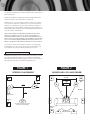
POSITIONING YOUR SYNERGY SERIES SUBWOOFER
Klipsch powered subwoofers are designed to reproduce deep bass and deliver the impact that
makes your movies and music come alive. For optimum performance, place your subwoofer in a
corner of the room on the same wall as your front channel speakers. (refer to Figures 1 and 2).
Please note that room placement can have a dramatic effect upon the performance of your
powered subwoofer. Corner placement, as suggested above, will increase the amount of bass
output, while placing the subwoofer along the middle of a wall, or out in the room will decrease the
amount of bass output. Experiment with a number of different placement options and control
settings to find the one that best suits your particular room and taste. When choosing your
subwoofer’s location, keep in mind that you will need to connect the subwoofer’s built-in amplifier
to an AC power outlet.
ENGLISH
CONNECTIONS AND CONTROLS
Optimal Connections – Klipsch Synergy Powered subwoofers can be connected to the subwoofer
output of your electronics via the RCA jack inputs (“LINE IN”) on the subwoofer’s rear panel (refer
to Figure 3). This can be in place of the conventional speaker wire connections (“HIGH LEVEL IN”).
For more information on the controls mentioned in this manual and on bass management, see
your dealer or visit www.klipsch.com.
WARRANTY — U.S. AND CANADA ONLY
The Warranty below is valid only for sales to consumers in the United States or Canada.
KLIPSCH, L.L.C. ("KLIPSCH") warrants this product to be free from defects in materials and
workmanship (subject to the terms set forth below) for a period of five (5) years from the date of
purchase. During the Warranty period, KLIPSCH will repair or replace (at KLIPSCH’s option) this
product or any defective parts (excluding electronics and amplifiers). For products that have
electronics or amplifiers, the Warranty on those parts is for a period of two (2) years from the
date of purchase.
To obtain Warranty service, please contact the KLIPSCH authorized dealer from which you
purchased this product. Proof of purchase in the form of a bill of sale or receipted invoice, which is
evidence that this product is within the Warranty period, must be presented or included to obtain
Warranty service.
This Warranty is invalid if (a) the factory-applied serial number has been altered or removed from this
product or (b) this product was not purchased from a KLIPSCH authorized dealer. You may call
1-800-KLIPSCH to confirm that you have an unaltered serial number and/or you purchased from a
KLIPSCH authorized dealer.
This Warranty is only valid for the original purchaser and will automatically terminate prior to
expiration if this product is sold or otherwise transferred to another party.
This Warranty does not cover cosmetic damage or damage due to misuse, abuse, negligence,
acts of God, accident, commercial use or modification of, or to any part of, the product. This
Warranty does not cover damage due to improper operation, maintenance or installation, or
attempted repair by anyone other than KLIPSCH or a KLIPSCH dealer which is authorized to do
KLIPSCH warranty work. Any unauthorized repairs will void this Warranty. This Warranty does not
cover product sold AS IS or WITH ALL FAULTS.
REPAIRS OR REPLACEMENTS AS PROVIDED UNDER THIS WARRANTY ARE THE EXCLUSIVE
REMEDY OF THE CONSUMER. KLIPSCH SHALL NOT BE LIABLE FOR ANY INCIDENTAL OR
CONSEQUENTIAL DAMAGES FOR BREACH OF ANY EXPRESS OR IMPLIED WARRANTY ON THIS
PRODUCT. EXCEPT TO THE EXTENT PROHIBITED BY LAW, THIS WARRANTY IS EXCLUSIVE AND IN
LIEU OF ALL OTHER EXPRESS AND IMPLIED WARRANTIES WHATSOEVER, INCLUDING BUT NOT
LIMITED TO, THE WARRANTY OF MERCHANTABILITY AND FITNESS FOR A PRACTICAL PURPOSE.
Some states do not allow the exclusion or limitation of incidental or consequential damages
or implied warranties so the above exclusions may not apply to you. This Warranty gives you
specific legal rights, and you may have other rights, which vary from state to state.
WARRANTY OUTSIDE THE UNITED STATES AND CANADA
The Warranty on this product if it is sold to a consumer outside of the United States or Canada
shall comply with applicable law and shall be the sole responsibility of the distributor that
supplied this product. To obtain any applicable warranty service, please contact the dealer from
which you purchased this product, or the distributor that supplied this product.
FIGURE 2
FIGURE 1
SURROUND LCR AND REARS
STEREO PLACEMENT
S
S
Sub
+ Optional
Sub
S
6'-15'
S
Sub
TV
+ Optional
Sub
C
L
R
X=Y=Z
X
Y
Z
Angle Inward
S
A
A
+ Optional
Sub
*Less distance will increase bass,
but worsen sound quality.
+ Optional
Sub
S
B
Alternate
rear placement
B
FIGURE 3
LOW LEVEL CONNECTIONS
LFE Output on Processor/
Pre-Amp/Receiver connected
to LFE input on subwoofer
amplifier
[OR]
Left & Right pre-outs on
Processor/Pre-Amp/Receiver
connected to Left & Right
line inputs on subwoofer amplifier
FIGURE 4
HIGH LEVEL CONNECTIONS
Main speaker outputs on receiver
connected to high level inputs on
subwoofer amplifier (Right is shown,
repeat for Left)
3502 Woodview Trace, Suite 200
Indianapolis, Indiana 46268 USA
.
1 800 . KLIPSCH • www.klipsch.com
High level outputs on subwoofer
amplifier connected to main
speaker inputs (Right is shown,
repeat for Left)