1
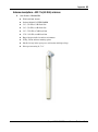
Avaya WLAN 2332 Series Outdoor
Solution Guide
Avaya WLAN 2300
Document Status: Standard
Document Number: NN47250-506 (324883-B Rev 02)
Document Version: 02.02
© 2010 Avaya Inc. All Rights Reserved.
Notices
While reasonable efforts have been made to ensure that the information in this document is complete and accurate at the
time of printing, Avaya assumes no liability for any errors. Avaya reserves the right to make changes and corrections to
the information in this document without the obligation to notify any person or organization of such changes.
Documentation disclaimer
Avaya shall not be responsible for any modifications, additions, or deletions to the original published version of this
documentation unless such modifications, additions, or deletions were performed by Avaya. End User agree to
indemnify and hold harmless Avaya, Avaya’s agents, servants and employees against all claims, lawsuits, demands and
judgments arising out of, or in connection with, subsequent modifications, additions or deletions to this documentation,
to the extent made by End User.
Link disclaimer
Avaya is not responsible for the contents or reliability of any linked Web sites referenced within this site or
documentation(s) provided by Avaya. Avaya is not responsible for the accuracy of any information, statement or
content provided on these sites and does not necessarily endorse the products, services, or information described or
offered within them. Avaya does not guarantee that these links will work all the time and has no control over the
availability of the linked pages.
Warranty
Avaya provides a limited warranty on this product. Refer to your sales agreement to establish the terms of the limited
warranty. In addition, Avaya’s standard warranty language, as well as information regarding support for this product,
while under warranty, is available to Avaya customers and other parties through the Avaya Support Web site: http://
www.avaya.com/support
Please note that if you acquired the product from an authorized reseller, the warranty is provided to you by said reseller
and not by Avaya.
Licenses
THE SOFTWARE LICENSE TERMS AVAILABLE ON THE AVAYA WEBSITE, HTTP://SUPPORT.AVAYA.COM/
LICENSEINFO/ ARE APPLICABLE TO ANYONE WHO DOWNLOADS, USES AND/OR INSTALLS AVAYA
SOFTWARE, PURCHASED FROM AVAYA INC., ANY AVAYA AFFILIATE, OR AN AUTHORIZED AVAYA
RESELLER (AS APPLICABLE) UNDER A COMMERCIAL AGREEMENT WITH AVAYA OR AN AUTHORIZED
AVAYA RESELLER. UNLESS OTHERWISE AGREED TO BY AVAYA IN WRITING, AVAYA DOES NOT
EXTEND THIS LICENSE IF THE SOFTWARE WAS OBTAINED FROM ANYONE OTHER THAN AVAYA, AN
AVAYA AFFILIATE OR AN AVAYA AUTHORIZED RESELLER, AND AVAYA RESERVES THE RIGHT TO
TAKE LEGAL ACTION AGAINST YOU AND ANYONE ELSE USING OR SELLING THE SOFTWARE
WITHOUT A LICENSE. BY INSTALLING, DOWNLOADING OR USING THE SOFTWARE, OR AUTHORIZING
OTHERS TO DO SO, YOU, ON BEHALF OF YOURSELF AND THE ENTITY FOR WHOM YOU ARE
INSTALLING, DOWNLOADING OR USING THE SOFTWARE (HEREINAFTER REFERRED TO
INTERCHANGEABLY AS "YOU" AND "END USER"), AGREE TO THESE TERMS AND CONDITIONS AND
CREATE A BINDING CONTRACT BETWEEN YOU AND AVAYA INC. OR THE APPLICABLE AVAYA
AFFILIATE ("AVAYA").
Copyright
Except where expressly stated otherwise, no use should be made of the Documentation(s) and Product(s) provided by
Avaya. All content in this documentation(s) and the product(s) provided by Avaya including the selection, arrangement
and design of the content is owned either by Avaya or its licensors and is protected by copyright and other intellectual
property laws including the sui generis rights relating to the protection of databases. You may not modify, copy,
reproduce, republish, upload, post, transmit or distribute in any way any content, in whole or in part, including any code
and software. Unauthorized reproduction, transmission, dissemination, storage, and or use without the express written
consent of Avaya can be a criminal, as well as a civil offense under the applicable law.
Third Party Components
Certain software programs or portions thereof included in the Product may contain software distributed under third
party agreements ("Third Party Components"), which may contain terms that expand or limit rights to use certain
portions of the Product ("Third Party Terms"). Information regarding distributed Linux OS source code (for those
Products that have distributed the Linux OS source code), and identifying the copyright holders of the Third Party
Components and the Third Party Terms that apply to them is available on the Avaya Support Web site: http://
support.avaya.com/Copyright.
Trademarks
The trademarks, logos and service marks ("Marks") displayed in this site, the documentation(s) and product(s)
provided by Avaya are the registered or unregistered Marks of Avaya, its affiliates, or other third parties. Users are not
permitted to use such Marks without prior written consent from Avaya or such third party which may own the Mark.
Nothing contained in this site, the documentation(s) and product(s) should be construed as granting, by implication,
estoppel, or otherwise, any license or right in and to the Marks without the express written permission of Avaya or the
applicable third party. Avaya is a registered trademark of Avaya Inc. All non-Avaya trademarks are the property of their
respective owners.
Downloading documents
For the most current versions of documentation, see the Avaya Support. Web site: http://www.avaya.com/support
Contact Avaya Support
Avaya provides a telephone number for you to use to report problems or to ask questions about your product. The
support telephone number is 1-800-242-2121 in the United States. For additional support telephone numbers, see the
Avaya Web site: http://www.avaya.com/support
3
Contents
Basics of Avaya WLAN Series 2332 Outdoor Solution..................................7
Introduction . . . . . . . . . . . . . . . . . . . . . . . . . . . . . . . . . . . . . . . . . . . . . . . . . . . . . . . 7
What is the Avaya WLAN Series 2332 Outdoor Solution . . . . . . . . . . . . . . . . . 7
Customer service . . . . . . . . . . . . . . . . . . . . . . . . . . . . . . . . . . . . . . . . . . . . . . . . . . . 8
Navigation . . . . . . . . . . . . . . . . . . . . . . . . . . . . . . . . . . . . . . . . . . . . . . . . . . . . . 8
Getting technical documentation . . . . . . . . . . . . . . . . . . . . . . . . . . . . . . . . . . . . 8
Getting product training . . . . . . . . . . . . . . . . . . . . . . . . . . . . . . . . . . . . . . . . . . . 8
Getting help from a distributor or reseller . . . . . . . . . . . . . . . . . . . . . . . . . . . . . 8
Getting technical support from the Avaya Web site . . . . . . . . . . . . . . . . . . . . . 8
Regulatory compliance statements for WLAN Series 2332 Access Points . . . . . . . 9
Federal Communications Commission (FCC) compliance notices . . . . . . . . . . 9
Class B interference statement . . . . . . . . . . . . . . . . . . . . . . . . . . . . . . . . . . 9
FCC caution . . . . . . . . . . . . . . . . . . . . . . . . . . . . . . . . . . . . . . . . . . . . . . . . 9
RF radiation exposure and hazard statement . . . . . . . . . . . . . . . . . . . . . . 10
Non-modification statement . . . . . . . . . . . . . . . . . . . . . . . . . . . . . . . . . . . 10
Deployment statement . . . . . . . . . . . . . . . . . . . . . . . . . . . . . . . . . . . . . . . 10
Dynamic Frequency Selection (DFS) in the 5.0 GHz UNII bands . . . . . . 10
Canadian IC statement . . . . . . . . . . . . . . . . . . . . . . . . . . . . . . . . . . . . . . . . . . 10
European Union and European Free Trade Association (EFTA) regulatory
compliance . . . . . . . . . . . . . . . . . . . . . . . . . . . . . . . . . . . . . . . . . . . . . . . . . . . 11
Declaration of conformity . . . . . . . . . . . . . . . . . . . . . . . . . . . . . . . . . . . . . 11
European Community declaration of conformity . . . . . . . . . . . . . . . . . . . . . . . 12
Countries of operation and restrictions of use in the European Community . . 14
Operation using the 2.400 to 2.4835 GHz channels in the European
Community . . . . . . . . . . . . . . . . . . . . . . . . . . . . . . . . . . . . . . . . . . . . . . . . 14
Operation using the 5.15 to 5.25 GHz, 5.25 to 5.35 GHz,
and 5.470 to 5.725 GHz channels in the European Community . . . . . . . . 15
Dynamic Frequency Selection (DFS) . . . . . . . . . . . . . . . . . . . . . . . . . . . . 15
Transmit Power Control (TPC) . . . . . . . . . . . . . . . . . . . . . . . . . . . . . . . . . 15
Korea MIC Compliance Statement . . . . . . . . . . . . . . . . . . . . . . . . . . . . . . . . . 15
Taiwan Compliance Statement . . . . . . . . . . . . . . . . . . . . . . . . . . . . . . . . . . . . 16
Outdoor Operating Restrictions . . . . . . . . . . . . . . . . . . . . . . . . . . . . . . . . . . . . . . . 18
Avaya WLAN Series 2332 Outdoor Solution Guide
4 Contents
United States and Canada . . . . . . . . . . . . . . . . . . . . . . . . . . . . . . . . . . . . 18
2.4 GHz Band . . . . . . . . . . . . . . . . . . . . . . . . . . . . . . . . . . . . . . . . . . . . . . 18
5.0 GHz Bands . . . . . . . . . . . . . . . . . . . . . . . . . . . . . . . . . . . . . . . . . . . . . 18
European Union (EU) and European Fair Trade Association (EFTA) . . . . 18
2.4 GHz Band . . . . . . . . . . . . . . . . . . . . . . . . . . . . . . . . . . . . . . . . . . . . . . 18
5.0 GHz Bands . . . . . . . . . . . . . . . . . . . . . . . . . . . . . . . . . . . . . . . . . . . . . 19
Country Specific Outdoor Operation Restrictions . . . . . . . . . . . . . . . . . . . . . . 20
External Antenna Statement . . . . . . . . . . . . . . . . . . . . . . . . . . . . . . . . . . . . . . 22
Country Specific External Antenna Restrictions . . . . . . . . . . . . . . . . . . . . . . . 22
Translated caution statements, warning conventions and warning messages . . . 24
WLAN Series 2332 Outdoor Solution with Indoor Mounted AP..................39
Introduction . . . . . . . . . . . . . . . . . . . . . . . . . . . . . . . . . . . . . . . . . . . . . . . . . . . . . . 39
Kit Contents . . . . . . . . . . . . . . . . . . . . . . . . . . . . . . . . . . . . . . . . . . . . . . . . . . . 39
Package contents . . . . . . . . . . . . . . . . . . . . . . . . . . . . . . . . . . . . . . . . . . . . . . 40
Basic outdoor installation information . . . . . . . . . . . . . . . . . . . . . . . . . . . . . . . . . . 41
Signal path distance . . . . . . . . . . . . . . . . . . . . . . . . . . . . . . . . . . . . . . . . . 41
Signal attenuation and loss in outdoor installations . . . . . . . . . . . . . . . . . 41
Antenna polarization . . . . . . . . . . . . . . . . . . . . . . . . . . . . . . . . . . . . . . . . . 41
Signal path clearance . . . . . . . . . . . . . . . . . . . . . . . . . . . . . . . . . . . . . . . . 41
Physical site survey . . . . . . . . . . . . . . . . . . . . . . . . . . . . . . . . . . . . . . . . . 41
Hardware installation . . . . . . . . . . . . . . . . . . . . . . . . . . . . . . . . . . . . . . . . . . . . . . . 43
Required components . . . . . . . . . . . . . . . . . . . . . . . . . . . . . . . . . . . . . . . . 43
Outdoor external antenna connection scenarios . . . . . . . . . . . . . . . . . . . . . . . 44
Surge suppressor (lightning arrestor) . . . . . . . . . . . . . . . . . . . . . . . . . . . . 46
Installation . . . . . . . . . . . . . . . . . . . . . . . . . . . . . . . . . . . . . . . . . . . . . . . . . 47
Grounding principles . . . . . . . . . . . . . . . . . . . . . . . . . . . . . . . . . . . . . . . . . 48
Outdoor external antennas . . . . . . . . . . . . . . . . . . . . . . . . . . . . . . . . . . . . . . . 50
Coax cable seal installation . . . . . . . . . . . . . . . . . . . . . . . . . . . . . . . . . . . 51
Physical site survey . . . . . . . . . . . . . . . . . . . . . . . . . . . . . . . . . . . . . . . . . 52
Software installation . . . . . . . . . . . . . . . . . . . . . . . . . . . . . . . . . . . . . . . . . . . . . . . . 53
Country of operation . . . . . . . . . . . . . . . . . . . . . . . . . . . . . . . . . . . . . . . . . . . . 53
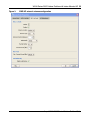
Use of external antenna configuration option CLI and WMS . . . . . . . . . . 53
Specifying the external antenna model . . . . . . . . . . . . . . . . . . . . . . . . . . . 53
Other related documentation references . . . . . . . . . . . . . . . . . . . . . . . . . . . . . . . . 56
NN47250-506 (324883-B Rev 02 Version 02.02)
Contents 5
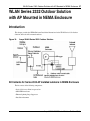
WLAN Series 2332 Outdoor Solution with AP Mounted in NEMA Enclosure
57
Introduction . . . . . . . . . . . . . . . . . . . . . . . . . . . . . . . . . . . . . . . . . . . . . . . . . . . . . . 57
Kit Contents for Series 2332 AP installed outdoors in NEMA Enclosure . . . . 57
Site Planning . . . . . . . . . . . . . . . . . . . . . . . . . . . . . . . . . . . . . . . . . . . . . . . . . . 58
Ethernet . . . . . . . . . . . . . . . . . . . . . . . . . . . . . . . . . . . . . . . . . . . . . . . . . . 58
Antenna . . . . . . . . . . . . . . . . . . . . . . . . . . . . . . . . . . . . . . . . . . . . . . . . . . 58
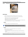
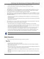
Safety Precautions . . . . . . . . . . . . . . . . . . . . . . . . . . . . . . . . . . . . . . . . . . . . . 59
Powerline . . . . . . . . . . . . . . . . . . . . . . . . . . . . . . . . . . . . . . . . . . . . . . . . . 59
Installation . . . . . . . . . . . . . . . . . . . . . . . . . . . . . . . . . . . . . . . . . . . . . . . . . 60
Heat/Cold loading . . . . . . . . . . . . . . . . . . . . . . . . . . . . . . . . . . . . . . . . . . . 60
Reference Information . . . . . . . . . . . . . . . . . . . . . . . . . . . . . . . . . . . . . . . . . . . 60
Ethernet and Antenna Lightning Surge Protector . . . . . . . . . . . . . . . . . . . 60
Applying coax seal tape . . . . . . . . . . . . . . . . . . . . . . . . . . . . . . . . . . . . . . 61
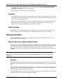
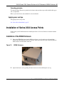
Installation of Series 2332 Access Points . . . . . . . . . . . . . . . . . . . . . . . . . . . . . . . 61
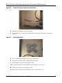
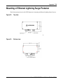
Installation of the NEMA Enclosure . . . . . . . . . . . . . . . . . . . . . . . . . . . . . . . . . 61
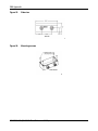
Installation of the Ethernet Lightning Surge Protector . . . . . . . . . . . . . . . . . . . 65
Terminal Strip Connection . . . . . . . . . . . . . . . . . . . . . . . . . . . . . . . . . . . . . 66
Software . . . . . . . . . . . . . . . . . . . . . . . . . . . . . . . . . . . . . . . . . . . . . . . . . . . . . 67
Country of operation . . . . . . . . . . . . . . . . . . . . . . . . . . . . . . . . . . . . . . . . . 67
Appendix..........................................................................................................69
Supported antenna information . . . . . . . . . . . . . . . . . . . . . . . . . . . . . . . . . . . . 69
Outdoor external antenna options . . . . . . . . . . . . . . . . . . . . . . . . . . . . . . . . . . 69
Surge Suppression . . . . . . . . . . . . . . . . . . . . . . . . . . . . . . . . . . . . . . . . . . . . . 70
Antenna properties and considerations . . . . . . . . . . . . . . . . . . . . . . . . . . . . . . 78
Antenna properties . . . . . . . . . . . . . . . . . . . . . . . . . . . . . . . . . . . . . . . . . . . . . 78
RF Propagation and Path Loss . . . . . . . . . . . . . . . . . . . . . . . . . . . . . . . . . . . . 82
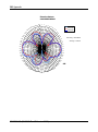
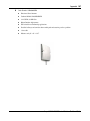
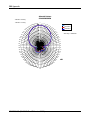
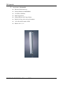
Antenna descriptions – 802.11a (5.0 GHz) antennas . . . . . . . . . . . . . . . . 85
Antenna descriptions – 802.11b/g (2.4GHz) antennas . . . . . . . . . . . . . . 104
Mounting of Ethernet Lightning Surge Protector . . . . . . . . . . . . . . . . . . . . . . . . . 119
Avaya WLAN Series 2332 Outdoor Solution Guide
6 Contents
NN47250-506 (324883-B Rev 02 Version 02.02)
Basics of Avaya WLAN Series 2332 Outdoor Solution 7
Basics of Avaya WLAN Series 2332
Outdoor Solution
Introduction
This document provides the basic outdoor hardware installation instructions for your WLAN Series 2332.
For information about WLAN Series 2332 Outdoor Solution with Indoor Mounted AP, refer Chapter ,
“WLAN Series 2332 Outdoor Solution with Indoor Mounted AP,” on page 39
For information about WLAN Series 2332 Outdoor Solution with AP Mounted in NEMA Enclosure, refer
Chapter , “WLAN Series 2332 Outdoor Solution with AP Mounted in NEMA Enclosure,” on page 57
For more information about AP installation as well as safety and installation requirements, see the following:
•
Avaya WLAN Series 2332 Access Point Installation Guide
What is the Avaya WLAN Series 2332 Outdoor Solution
The Avaya WLAN Series 2332 Outdoor Solution is the incorporation of existing and new Avayacomponents
to provide a simple yet effective solution to wireless LAN access in outdoor locations.
Note. WLAN Series 2332 Access Points require WMS software Release 6.0.7.1 (or later)
and WSS software Release 6.0.6.2 (or later) for correct configuration and operation.
Avaya WLAN Series 2332 Outdoor Solution Guide
8 Basics of Avaya WLAN Series 2332 Outdoor Solution
Customer service
Visit the Avaya Web site to access the complete range of services and support that Avaya provides. Go to
www.avaya.com or go to one of the pages listed in the following sections.
Navigation
•
See “Getting technical documentation” page 8
•
See “Getting product training” page 8
•
See “Getting help from a distributor or reseller” page 8
•
See “Getting technical support from the Avaya Web site” page 8
Getting technical documentation
To download and print selected technical publications and release notes directly from the Internet, go to
www.avaya.com/support.
Getting product training
Ongoing product training is available. For more information or to register, you can access the Web site at
www.avaya.com/support. From this Web site, you can locate the Training contacts link on the left-hand
navigation pane.
Getting help from a distributor or reseller
If you purchased a service contract for your Avaya product from a distributor or authorized reseller, contact the
technical support staff for that distributor or reseller for assistance.
Getting technical support from the Avaya Web site
The easiest and most effective way to get technical support for Avaya products is from the Avaya Technical
Support Web site at www.avaya.com/support.
NN47250-506 (324883-B Version 02.02)
Basics of Avaya WLAN Series 2332 Outdoor Solution 9
Regulatory compliance statements for WLAN Series
2332 Access Points
The WLAN Series 2332 Access Points consist of the following models:
2332-A1, 2332-A2, 2332-A3, 2332-A4, 2332-A5, 2332-A6, 2332-E1, 2332-E2, 2332-E3, 2332-E4, 2332-E5,
2332-E6, 2332-E7, 2332-E8, 2332-E9, 2332-J1.
Federal Communications Commission (FCC) compliance notices
This section includes the following FCC statements for the WLAN Series 2332 Access Points:
•
FCC ID: RVW2332 (Applies to 2332-A1)
•
Class B Interference Statement
•
RF Radiation Exposure and Hazard Warning
•
Non-Modification Statement
•
Deployment Statement
Class B interference statement
This equipment has been tested and found to comply with the limits for a Class B digital device, pursuant to
Part 15 of the FCC Rules. These limits are designed to provide reasonable protection against harmful
interference in a residential installation. This equipment generates, uses, and can radiate radio frequency
energy and, if not installed and used in accordance with the instructions, may cause harmful interference to
radio communications. However, there is no guarantee that interference will not occur in a particular
installation. If this equipment does cause harmful interference to radio or television reception, which can be
determined by turning the equipment off and on, the user is encouraged to try to correct the interference by one
or more of the following measures:
•
Reorient or relocate the receiving antenna.
•
Increase the separation between the equipment and receiver.
•
Connect the equipment into an outlet on a circuit different from that to which the receiver is connected.
•
Consult the dealer or an experienced radio/TV technician for help.
FCC caution
This device complies with Part 15 of the FCC Rules. Operation is subject to the following two conditions: (1)
This device may not cause harmful interference, and (2) this device must accept any interference received,
including interference that may cause undesired operation.
Avaya WLAN Series 2332 Outdoor Solution Guide
10 Basics of Avaya WLAN Series 2332 Outdoor Solution
RF radiation exposure and hazard statement
To ensure compliance with FCC RF exposure requirements, this device must be installed in a location such
that the antenna of the device will be greater than 20 cm (8 in.) away from all persons. Using higher gain
antennas and types of antennas not covered under the FCC certification of this product is not allowed.
Installers of the radio and end users of the product must adhere to the installation instructions provided in this
manual. This transmitter must not be co-located or operating in conjunction with any other antenna or
transmitter.
Non-modification statement
Use only the supplied internal antenna, or external antennas supplied by the manufacturer. Unauthorized
antennas, modifications, or attachments could damage the WLAN 2332-A1 and related Series 2332 Access
Points and violate FCC regulations. Any changes or modifications not expressly approved by the party
responsible for compliance could void the user's authority to operate this equipment. Contact Avaya for a list
of approved 2.4 GHz and 5.0 GHz external antennas.
This device must be operated with the CAT-5 Ethernet cable installed on each activated Ethernet Port of a
Series 2332 Access Point to ensure compliance with the Class B emissions standards. Failure to comply with
this installation requirement may cause the device to operate in excess of the allowable emissions limits.
Deployment statement
This product is certified for indoor deployment only. Outdoor operation is allowed by exception only.
Please follow the guidelines outlined in the Outdoor Operation Section in this guide.
Dynamic Frequency Selection (DFS) in the 5.0 GHz UNII bands
The 2332-A1 access point has been prohibited, via software, from operating in the 5250 to 5350 MHz and
5470 to 5725 MHz frequency bands for the US and Canada because it cannot meet the DFS requirements as
outlined in the rules of the FCC for Part 15, Subpart E that went into force on July 20, 2007.
Canadian IC statement
IC: 332R-2332 (Applies to 2332-A1).
Operation is subject to the following two conditions in Canada:
1
this device may not cause interference, and
2
this device must accept any interference, including interference that may cause undesired operation of the
device
To prevent radio interference to the licensed service (i.e. co-channel Mobile Satellite systems) this device is
intended to be operated indoors and away from windows to provide maximum shielding. Equipment (or its
transmit antenna) that is installed outdoors is subject to licensing and not supported by the WLAN 2332-A1
Access Point.
NN47250-506 (324883-B Version 02.02)
Basics of Avaya WLAN Series 2332 Outdoor Solution 11
European Union and European Free Trade Association (EFTA) regulatory
compliance
This equipment may be operated in the countries that comprise the member countries of the European Union
and the European Free Trade Association. These countries, listed in the following paragraph, are referred to as
The European Community throughout this document:
AUSTRIA, BELGIUM, BULGARIA, CYPRUS, CZECH REPUBLIC, DENMARK, ESTONIA, FINLAND,
FRANCE, GERMANY, GREECE, HUNGARY, IRELAND, ITALY, LATVIA, LITHUANIA,
LUXEMBOURG, MALTA, NETHERLANDS, POLAND, PORTUGAL, ROMANIA, SLOVAKIA,
SLOVENIA, SPAIN, SWEDEN, UNITED KINGDOM, ICELAND, LICHTENSTEIN, NORWAY,
SWITZERLAND
The WLAN 2332-E1 and related Series 2332 Access Points communicate with Avaya
WLAN - Security Switch using a standard CAT-5 (Category 5) or higher 10/100 Mbps twisted pair Ethernet
cable to provide wireless local area networking (WLAN) capabilities. The WLAN 2332-E1 and related Series
2332 Access Points include one 802.11a and one 802.11b/g radio and two 802.11a and two 802.11b/g
omnidirectional internal antennas. In addition, the 2332-E1 and related Series 2332 Access Points can use
optional factory-supplied external omnidirectional and/or directional high-gain antennas, one per the
802.11b/g and one per the 802.11a radios, as described in the external antenna section of the WLAN
Series 2332 Access Point Installation Guide. When using the external antennas, connect them to the
reverse-polarity R-SMA connectors located on the side of the WLAN 2332-E1 or related Series 2332
Access Point.
Declaration of conformity
Marking by this symbol
indicates compliance with the Essential Requirements of the R&TTE Directive of the European Union
(1999/5/EC). This equipment meets the following conformance standards:
Safety: EN 60950-1:2001 + A11:2004
EMC: EN 55022: 2006, EN 55024:1998 + A1:2001 + A2:2003, EN301489-1 V.1.6.1,
EN 301489-17 v1.2.1, CISPR22:1997, CISPR24
Including: EN 61000-3-2, -3-3, -4-2, -4-3, -4-4, -4-5, -4-6 and -4-11. The product is also licensed as
required for additional country specific standards as required for the International Marketplace.
Radio: EN 300-328 v.1.7.1 (2006-10) & EN 301-893 v.1.4.1 (2007-07)
DEVIATION: The 2332-E1 and related Series 2332 access points were tested to and are compliant with
all of the technical specifications of EN 301-893 v1.4.1 for operation in the 5.0 GHz bands, except the
DFS requirements in the 5600 – 5650 MHz band.
IEEE 802.11a operation in the 5250 to 5350 MHz and 5470 to 5725 MHz frequency bands is governed by
ETSI EN 301-893 v1.4.1 and the R&TTE Directive 1999/5/EC. Effective July 1, 2008, EN 301-893
v1.4.1 was updated to require compliance with 0.8 µsecond pulse widths and staggered PRF’s in the
5470 – 5725 MHz band. The 2332-E1 access point meets compliance with these new mandates by
disabling operation, via software, on channels 120, 124, 128 and 132 in the 5600 to 5650 MHz frequency
band because it cannot meet the 0.8 µsecond pulse width and staggered PRF DFS requirements as
outlined in the updated EN 301-893v1.4.1 standard.
Avaya WLAN Series 2332 Outdoor Solution Guide
12 Basics of Avaya WLAN Series 2332 Outdoor Solution
Electromagnetic compatibility and Radio spectrum Matters (ERM); Wideband transmission systems;
Data transmission equipment operating in the 2,4 GHz ISM band and using wide band modulation
techniques and Broadband Radio Access Networks (BRAN); 5 GHz high performance RLAN.
Certifications are harmonized to the EN standards covering essential requirements under article 3.2 of the
R&TTE Directive. Compliance includes testing with antennas as specified in attached table.
SAR: EN 50385:2002
European Community declaration of conformity
WLAN Radio Model 2332, as stated in the following Declarations of Conformity, represents all models in the
Series 2332 as listed above.
Bulgaria
български
С това, avaya обявява, че този модел на радио на WLAN Радио Модел
2332, е със съгласие с съществените изисквания и други важни условия
на директива 1999/5 на европейски съюз
Czech Republic
Èesky
Avayatímto prohlašuje, že tento WLAN Rádio Model 2332, je ve shodì se
základními požadavky a dalšími pøíslušnými ustanoveními smìrnice
1999/5/ES.
Denmark
Dansk
Undertegnede Avayaerklærer herved, at følgende udstyr WLAN Radio Model
2332, overholder de væsentlige krav og øvrige relevante krav i direktiv
1999/5/EF.
English
English
Hereby, Avaya declares that this WLAN Radio Model 2332, is in compliance
with the essential requirements and other relevant provisions of Directive
1999/5/EC.
Estonia
Eesti
Käesolevaga kinnitab Avayaseadme WLAN Radio Model 2332, vastavust
direktiivi 1999/5/EÜ põhinõuetele ja nimetatud direktiivist tulenevatele
teistele asjakohastele sätetele.
Finland
Suomi
Avayavakuuttaa täten että WLAN Radio Esikuvallinen 2332, tyyppinen laite
on direktiivin 1999/5/EY oleellisten vaatimusten ja sitä koskevien direktiivin
muiden ehtojen mukainen.
France
Français
Par la présente Avayadéclare que l'appareil Model Par radio 2332 de
WLAN, est conforme aux exigencies essentielles et aux autres dispositions
pertinentes de la directive 1999/5/CE.
NN47250-506 (324883-B Version 02.02)
Basics of Avaya WLAN Series 2332 Outdoor Solution 13
Germany
Deutsch
Hiermit erklärt Avaya., dass sich das Gerät WLAN Radiomodell 2332, in
Übereinstimmung mit den grundlegenden Anforderungen und den übrigen
einschlägigen Bestimmungen der Richtlinie 1999/5/EG befindet.
Greece
ΕΛΛΗΝΙΚΗ
ÌÅ ÔÇÍ ÐÁÑÏÕÓÁ Avaya. ÇË.ÍÅÉ ÏÔÉ WLAN ραδιο πρότυπο 2332,
ÓÕÌÌÏÑÖ.ÍÅÔÁÉ ÐÑÏÓ ÔÉÓ ÏÕÓÉ..ÅÉÓ ÁÐÁÉÔÇÓÅÉÓ ÊÁÉ ÔÉÓ
ËÏÉÐÅÓ Ó×ÅÔÉÊÅÓ .ÉÁÔÁÎÅÉÓ ÔÇÓ Ï.ÇÃÉÁÓ 1999/5/ÅÊ.
Hungary
Magyar
Alulírott, Avayanyilatkozom, hogy a WLAN Rádió Minta 2332, megfelel a
vonatkozó alapvetõ követelményeknek és az 1999/5/EC irányelv egyéb
elõírásainak.
Italy
Italiano
Con la presente Avayadichiara che questo Modello Radiofonico 2332 di
WLAN, è conforme ai requisiti essenziali ed alle alter disposizioni pertinenti
stabilite dalla direttiva 1999/5/CE.
Latvia
Latviski
Ar šo Avayadeklarç, ka WLAN Radio Model 2332, atbilst Direktîvas
1999/5/EK bûtiskajâm prasîbâm un citiem ar to saistîtajiem noteikumiem.
Lithuania
Lietuviø
Šiuo Avayadeklaruoja, kad šis WLAN Radio Model 2332, atitinka esminius
reikalavimus ir kitas 1999/5/EB Direktyvos nuostatas.
Malta
Malti
Hawnhekk, Avaya., jiddikjara li dan WLAN Radio Model 2332, jikkonforma
mal-tiijiet essenzjali u ma provvedimenti orajn relevanti li hemm
fid-Dirrettiva 1999/5/EC.
Netherlands
Netherlands
Hierbij verklaart Avayadat het toestel WLAN Radiomodel 2332, in
overeenstemming is met de essentiële eisen en de andere relevante bepalingen
van richtlijn 1999/5/EG.
Poland
Polski
Niniejszym Avayaooewiadcza, ¿e WLAN Radio Model 2332, jest zgodny z
zasadniczymi wymogami oraz pozosta³ymi stosownymi postanowieniami
Dyrektywy 1999/5/EC.
Portugal
Português
Avayadeclara que este Modelo De rádio 2332 de WLAN, está conforme
com os requisitos essenciais e outras disposições da Directiva 1999/5/CE.
Avaya WLAN Series 2332 Outdoor Solution Guide
14 Basics of Avaya WLAN Series 2332 Outdoor Solution
Romania
Român
Astfel, Avaya declarã acel acest WLAN Radio Model 2332, este în
conformitate cu cerinþele necesare ºi proviziile alte semnificative de Directive
1999 5 EC.
Slovakia
Slovensky
Avayatýmto vyhlasuje, že WLAN Radio Model 2332 spåòa základné
požiadavky a všetky príslušné ustanovenia Smernice 1999/5/ES.
Slovenia
Slovensko
Avayaizjavlja, da je ta WLAN Radio Model 2332, v skladu z bistvenimi
zahtevami in ostalimi relevantnimi doloèili directive 1999/5/ES.
Spain
Español
Por medio de la presente Avayadeclara que el Modelo De radio 2332 de
WLAN, cumple con los requisitos esenciales y cualesquiera otras
disposiciones aplicables o exigibles de la Directiva 1999/5/CE.
Sweden
Svenska
Härmed intygar Avayaatt denna WLAN Radiotelegrafera till Modell 2332, står I
överensstämmelse med de väsentliga egenskapskrav och övriga relevanta
bestämmelser som framgår av direktiv 1999/5/EG.
Countries of operation and restrictions of use in the European
Community
Operation using the 2.400 to 2.4835 GHz channels in the European Community
The professional installer should use the configuration utility provided with this product to verify the current
channel of operation, the expected transmit power level, and to confirm that the device is operating in
conformance with the spectrum usage rules for the selected European Community country. If operation is
occurring outside of the allowable channels as indicated in this guide, then operation of the product must cease
immediately and the installer must consult with the local technical support staff responsible for the wireless
network.
This device is intended to be operated in all countries of the European Community. Additional restrictions of
use for the 2332-E1 and related Series 2332 Access Points within the European Community countries in the
2.400 to 2.4835 GHz band are listed below.
•
The frequencies associated with channels 1 to 13 in the 2.400 to 2.4835 GHz band are allowed to be used
either indoors or outdoors in all countries of the European Community, except where noted in the
Outdoor Operation Section.
The 2332-E1 and related Series 2332 Access Points, whether using the internal or approved external antennas,
is guaranteed to meet this limit by automatically adjusting the transmit power level through the operating
software depending upon the gain of the selected antenna.
NN47250-506 (324883-B Version 02.02)
Basics of Avaya WLAN Series 2332 Outdoor Solution 15
Operation using the 5.15 to 5.25 GHz, 5.25 to 5.35 GHz,
and 5.470 to 5.725 GHz channels in the European Community
To remain in conformance with European National spectrum usage laws, follow the channel limitations
associated with the 5 GHz bands as specified in this document. The professional installer should verify the
current channel of operation and the expected transmit power level of the 2332-E1 or related Series 2332
Access Point to confirm that the device is operating in conformance with the spectrum usage rules for the
European Community country where the unit is being installed. If operation is occurring outside of the
allowable frequencies or above the power levels, as indicated in this guide, then operation of the product must
cease immediately and the installer must consult with the local technical support staff responsible for the
wireless network.
This device is intended to be operated in all countries of the European Community. Additional restrictions of
use for the 2332-E1 and related Series 2332 Access Points within the European Community countries in the
5.15 to 5.25 GHz, 5.25 to 5.35 GHz, and 5.470 to 5.725 GHz bands are listed below.
•
This device is restricted to indoor use only when operated in the European Community using the
5.15-5.25 GHz and 5.25-5.35 GHz bands, which includes channels 36, 40, 44, 48, 52, 56, 60 and 64.
•
The 5 GHz Turbo Mode feature is not allowed for operation in any European Community country.
Dynamic Frequency Selection (DFS)
The 2332-E1 and related Series 2332 Access Points implement a DFS feature in accordance with the limits in
EN 301-893v1.4.1, Section 4.7 and Annex D, Tables D.1, D.2 and D.4 for a device operating in the mode
defined as "Master". Section 4.7, Tables 5 of this document define the requirements prior to using a channel
and during normal operation for a Master device (i.e., Interference Detection Threshold, Channel Availability
Check Time, Uniform Spreading, Channel Closing Transmission Time and Channel Move Time). This product
qualifies for this category since the maximum achievable transmit power is greater than 23 dBm per the
requirements of Table D.2 in Annex D of the standard.
IEEE 802.11a operation in the 5250 to 5350 MHz and 5470 to 5725 MHz frequency bands is governed by
ETSI EN 301-893v1.4.1 and the R&TTE Directive 1999/5/EC. Effective July 1, 2008, EN 301-893 v1.4.1 was
updated to require compliance with 0.8 µsecond pulse widths and staggered PRF’s in the 5470 – 5725 MHz
band. The 2332-E1 access point meets compliance with these new mandates by disabling operation, via
software, on channels 120, 124, 128 and 132 in the 5600 to 5650 MHz frequency band because it cannot meet
the 0.8 µsecond pulse width and staggered PRF DFS requirements as outlined in the updated
EN 301-893v1.4.1 standard.
Transmit Power Control (TPC)
European Regulatory requirements specify that wireless devices must employ Transmit Power Control (TPC)
to reduce the potential for interference to other communication systems operating in the 5 GHz frequency
bands. This device includes a provision for adjustment of Transmit Power in accordance with the limits in EN
301-893v1.4.1, Sections 4.4.2.1 and 4.4.2.2.
Korea MIC Compliance Statement
Possible radio wave interference during operation of concerned radio equipment.
Avaya WLAN Series 2332 Outdoor Solution Guide
16 Basics of Avaya WLAN Series 2332 Outdoor Solution
B. For Home Use (Class B device)
This product obtained EMC Registration for home use. It can be used in all areas, including homes.
Taiwan Compliance Statement
Article 12
Without permission granted by the NCC, any company, enterprise, or user is not allowed to change frequency,
enhance transmitting power or alter original characteristic as well as performance to an approved low power
radio-frequency device.
Article 14
The low power radio-frequency devices shall not influence aircraft security and interfere with legal
communications. If found, the user shall cease operating immediately until no interference is achieved. The
said legal communications means radio communications is operated in compliance with the
Telecommunications Act.
The low power radio-frequency devices must be susceptible with the interference from legal communications
or ISM radio wave radiated devices.
NN47250-506 (324883-B Version 02.02)
Basics of Avaya WLAN Series 2332 Outdoor Solution 17
4.7.5 Within the 5.25-5.35 GHz band, U-NII devices will be restricted to indoor operations to reduce any
potential for harmful interference to co-channel MSS operations.
4.7.6 The operation of the U-NII devices is subject to the conditions that no harmful interference is caused.
The user must stop operating the device immediately should harmful interference be caused and shall not
resume until the condition causing the harmful interference has been corrected.
Moreover, the interference must be accepted that may be caused by the operation of an authorized
communications, or ISM equipment.
4.7.7 Manufacturers of U-NII devices are responsible for ensuring frequency stability such that an emission is
maintained within the band of operation under all conditions of normal operation as specified in the user
manual.
Avaya WLAN Series 2332 Outdoor Solution Guide
18 Basics of Avaya WLAN Series 2332 Outdoor Solution
Outdoor Operating Restrictions
United States and Canada
2.4 GHz Band
IEEE 802.11b/g operation in the 2.400 to 2.4835 GHz ISM band is governed by FCC Part 15, Subparts B & C
in the US and IC RSS-210 in Canada. These rules state that the parameters for both indoor and outdoor
operation in this frequency band are identical.
5.0 GHz Bands
IEEE 802.11a operation in the following frequency bands, is governed by FCC Part 15, Subparts B & C and
FCC Part 15, Subpart E for the US and IC RSS-210, Issue 6 in Canada. There are restrictions of use in the
5.0 GHz frequency bands and they are outlined below:
Table 1: Restrictions of use in 5.0 GHz frequency bands
5150 to 5250 MHz:
Operation is restricted to INDOOR use ONLY (FCC Part 15.400 & IC
RSS-210)
5250 to 5350 MHz:
Operation can be used indoors or outdoors (FCC Part 15.400 & IC RSS-210)
5470 to 5725 MHz:
Operation can be used indoors or outdoors (FCC Part 15.400 & IC RSS-210)
5725 to 5825 MHz:
Operation can be used indoors or outdoors (FCC Part 15.400 & IC RSS-210)
5725 to 5875 MHz:
Operation can be used indoors or outdoors (FCC Part 15.247)
The software settings that govern the operating parameters of the 2332-A1 Access Point have been constructed
to prohibit operation in the 5150 to 5250 MHz band when either "outdoor" mode or an "outdoor antenna
configuration" is selected. Please refer to the External Antenna Selection Guide for a complete listing of the
indoor and outdoor antennas.
In addition, the 2332-A1 Access Point has been prohibited, via software, from operating in the
5250 to 5350 MHz and 5470 to 5725 MHz frequency bands because it cannot meet the DFS requirements as
outlined in the rules of the FCC for Part 15, Subpart E that come into force on July 20, 2007.
European Union (EU) and European Fair Trade Association (EFTA)
2.4 GHz Band
IEEE 802.11b/g operation in the 2400 to 2483.5 MHz WLAN band is governed by ETSI EN 300-328 v1.7.1.
These rules state that the parameters for both indoor and outdoor operation in this frequency band are identical
in all member states, except those listed below:
NN47250-506 (324883-B Version 02.02)
Basics of Avaya WLAN Series 2332 Outdoor Solution 19
Table 2: Excepted member states
France:
Operation outdoors for IEEE 802.11b/g is limited to 2400 to 2454 MHz, channels 1 through 7,
at a maximum EIRP of 100 mW. The 2332-E1 Access Point is disabled from operating on
Channels 8 through 13 when either "outdoor" mode or an "outdoor antenna configuration" is
selected.
Italy:
Operation outdoors for IEEE 802.11b/g is prohibited without obtaining a license. If the
2332-E1 is to be used beyond the boundaries of the owner's property, a general authorization is
required from the Ministry of Communications. Please check http://www.comunicazioni.it/it
for further details. Operation on all channels has been prohibited when either "outdoor" mode
or an "outdoor antenna configuration" is selected.
Latvia:
Operation outdoors for IEEE 802.11b/g is prohibited without obtaining a license. If the
2332-E1 is to be used beyond the boundaries of the owner's property, outdoors or with an
outdoor antenna, a general authorization is first required from the Electronic Communications
Office. Please check http://www.esd.lv for further details. Operation on all channels has been
prohibited when either "outdoor" mode or an "outdoor antenna configuration" is selected.
5.0 GHz Bands
IEEE 802.11a operation in the frequency bands listed below, are governed by ETSI EN 301-893v 1.4.1 and the
R&TTE Directive 1999/5/EC. Effective July 1, 2008, EN 301-893 v1.4.1 was updated to require compliance
with 0.8 µsecond pulse widths and staggered PRF’s in the 5470 – 5725 MHz band. The 2332-E1 access point
meets compliance with these new mandates by disabling operation, via software, on channels 120, 124, 128
and 132 in the 5600 to 5650 MHz frequency band because it cannot meet the 0.8 µsecond pulse width and
staggered PRF DFS requirements as outlined in the updated EN 301-893v1.4.1 standard.
Table 3: Restrictions of use in 5.0 GHz frequency bands
5150 to 5250 MHz:
Operation is restricted to INDOOR use ONLY
5250 to 5350 MHz:
Operation is restricted to INDOOR use ONLY
5470 to 5725 MHz:
Operation can be used indoors or outdoors per EN 301-893893 v1.4.1
5725 to 5850 MHz:
Operation currently NOT ALLOWED or supported in the 2332-E1 Access
Point.
Operating parameters for both indoor and outdoor operation in the frequency bands listed above are identical
in all member states, except those listed below:
Table 4: Excepted Member States
France:
No operation is permitted in either the 5.25 to 5.35 GHz or 5.470 to 5.725 GHz bands because
the device is noncompliant with the DFS requirements stated in EN 301-893 v1.3.1. Therefore,
no outdoor operation is supported in France for the 2332-E1 Access Point.
Italy:
Operation outdoors for IEEE 802.11a is prohibited without obtaining a license. If the 2332-E1
is to be used beyond the boundaries of the owner's property, a general authorization is required
from the Ministry of communications. Please check http://www.comunicazioni.it/it for further
details. Operation on all channels has been prohibited when either "outdoor" mode or an
"outdoor antenna configuration" is selected.
Avaya WLAN Series 2332 Outdoor Solution Guide
20 Basics of Avaya WLAN Series 2332 Outdoor Solution
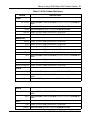
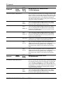
Country Specific Outdoor Operation Restrictions
The following restrictions of use for outdoor operation apply to the Series 2332 Access Points. These must be
followed to meet local regulatory restrictions and ensure that the access points operate in the appropriate
modes.
Table 5: 2.4 GHz Outdoor Restrictions
REGION
RESTRICTIONS
MIDDLE EAST
Egypt
Outdoor operation is NOT permitted in the 2.4 GHz band
Israel
Outdoor operation is permitted on Channels 5 to 13 ONLY
Jordan
Outdoor operation is NOT permitted in the 2.4 GHz band
Kuwait
Outdoor operation is NOT permitted in the 2.4 GHz band
Qatar
Outdoor operation is NOT permitted in the 2.4 GHz band
Saudi Arabia
Outdoor operation is NOT permitted in the 2.4 GHz band
United Arab Emirates Outdoor operation is NOT permitted in the 2.4 GHz band
AFRICA
Morocco
Cannot use antennas 24883, 24113, 24123 or 24143 for outdoor operation.
CALA
Mexico Channels 1 through 6 allowed for outdoor operation ONLY
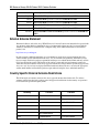
Table 6: 5.0 GHz Outdoor Restrictions
REGION
RESTRICTIONS
Europe
Russian Federation
Outdoor operation is NOT permitted in the 5.0 GHz bands
APAC
Australia
5150 to 5250 MHz and 5250 to 5350 MHz operation is restricted to INDOOR use
ONLY
Hong Kong 5150 to 5250 MHz and 5250 to 5350 MHz operation is restricted to INDOOR use
ONLY
India
Outdoor operation is NOT permitted in the 5.0 GHz bands
Indonesia Outdoor operation is NOT permitted in the 5.0 GHz bands
Japan
Outdoor operation is NOT permitted in the 5.0 GHz bands
NN47250-506 (324883-B Version 02.02)
Basics of Avaya WLAN Series 2332 Outdoor Solution 21
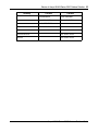
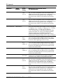
Table 6: 5.0 GHz Outdoor Restrictions
REGION
RESTRICTIONS
Europe
New Zealand
5150 to 5250 MHz and 5250 to 5350 MHz operation is restricted to INDOOR use
ONLY
Philippines 5150 to 5250 MHz operation is restricted to INDOOR use ONLY
Taiwan
5250 to 5350 MHz operation is restricted to INDOOR use ONLY
Thailand
Outdoor operation is NOT permitted in the 5.0 GHz bands
Vietnam
5150 to 5250 MHz operation is restricted to INDOOR use ONLY
MIDDLE EAST
Bahrain
Outdoor operation is NOT permitted in the 5.0 GHz bands
Egypt
Outdoor operation is NOT permitted in the 5.0 GHz bands
Israel
Outdoor operation is NOT permitted in the 5.0 GHz bands
Jordan
Outdoor operation is NOT permitted in the 5.0 GHz bands
Kuwait
Outdoor operation is NOT permitted in the 5.0 GHz bands
Oman 5150 to 5250 MHz and 5250 to 5350 MHz operation is restricted to INDOOR use
ONLY
Qatar
Outdoor operation is NOT permitted in the 5.0 GHz bands
Saudi Arabia
Outdoor operation is NOT permitted in the 5.0 GHz bands
United Arab Emirates Outdoor operation is NOT permitted in the 5.0 GHz bands
AFRICA
Kenya
5150 to 5250 MHz operation is restricted to INDOOR use ONLY
Mauritius 5150 to 5250 MHz and 5250 to 5350 MHz operation is restricted to INDOOR use
ONLY
Morocco
5150 to 5250 MHz operation is restricted to INDOOR use ONLY
AFRICA
South Africa
5150 to 5250 MHz and 5250 to 5350 MHz operation is restricted to INDOOR use
ONLY
Turkey
5150 to 5250 MHz and 5250 to 5350 MHz operation is restricted to INDOOR use
ONLY
CALA
Chile
Columbia
Outdoor operation is NOT permitted in the 5.0 GHz bands
5150 to 5250 MHz operation is restricted to INDOOR use ONLY
Avaya WLAN Series 2332 Outdoor Solution Guide
22 Basics of Avaya WLAN Series 2332 Outdoor Solution
Costa Rica
Outdoor operation is NOT permitted in the 5.0 GHz bands
Dominican Republic
5150 to 5250 MHz operation is restricted to INDOOR use ONLY
Jamaica
5150 to 5250 MHz operation is restricted to INDOOR use ONLY
Mexico 5150 to 5250 MHz operation is restricted to INDOOR use ONLY
Panama
5150 to 5250 MHz operation is restricted to INDOOR use ONLY
Peru 5150 to 5250 MHz operation is restricted to INDOOR use ONLY
Venezuela
5150 to 5250 MHz and 5250 to 5350 MHz operation is restricted to INDOOR use
ONLY
External Antenna Statement
Intentional radiators, such as the Avaya WLAN Series 2332 Access Point are not intended to be operated with
any antenna(s) other than those furnished by Avaya. An intentional radiator may only be operated with the
antenna(s) with which it is authorized. For a complete listing of the authorized antennas for use with this
product, visit
http://www.avaya.com/support
In order to ensure continued compliance, use of an antenna not on the Avaya approved antenna list is not
allowed without specific authorization from Avaya. Use of an antenna not specifically authorized by Avaya
may not comply with local regulatory requirements with respect to radiated emission limits and may result in
illegal operation of the product. The installer of the wireless system and associated antenna is required to
ensure that only those antennas on the Avaya approved antenna list or those antennas specifically approved by
Avaya on a case by case basis are deployed with the intentional radiator. Be sure to associate the appropriate
antenna model number and localized regulatory region when selecting the Avaya authorized antenna(s).
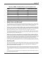
Country Specific External Antenna Restrictions
The following list of countries cannot use the Avaya approved antennas listed in the table. Use of these
antennas would violate the local regulatory rules and approved certifications for that country or operation is
not allowed in the specified frequency bands.
Country
2.4 GHz
5.0 GHz
Costa Rica
ALL antenna models
Indonesia
ALL antenna models
Japan
S51514WPN36RSM
S4901790PN36RS
SR49120DAN36RS
SR24120DN36RSM
Korea
S2406PN36RSM
NN47250-506 (324883-B Version 02.02)
S51514WPN36RSM
Basics of Avaya WLAN Series 2332 Outdoor Solution 23
Country
2.4 GHz
5.0 GHz
S2409PN36RSM
S4901790PN36RS
PC2415NA36RSM
SR49120DAN36RS
S241290PN36RSM
SR24120DN36RSM
Nigeria
ALL antenna models
Russian Federation
ALL antenna models
Thailand
ALL antenna models
Avaya WLAN Series 2332 Outdoor Solution Guide
24 Basics of Avaya WLAN Series 2332 Outdoor Solution
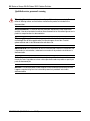
Translated caution statements, warning conventions
and warning messages
The following caution statement, warning conventions, and warning messages apply to this manual.
Caution! The Series 2332 Access Point radios are disabled by default and can be
enabled only by a system administrator using the WSS.
Attention! Les communications radios du Series 2332 Access Point sont désactivées
par défaut et peuvent être activées uniquement par un administrateur système utilisant le
WSS.
Achtung! Die Series 2332 Access Point Radios sind standardmäßig ausgeschaltet und
können nur durch einen Systemadministrator unter Verwendung des WSS eingeschaltet
werden.
Precaucion! Las radios Series 2332 Access Point se desactivan en forma
predeterminada y pueden activarse sólo con un administrador de sistema utilizando el
WSS.
Cuidado! Os rádios do Series 2332 Access Point estão desativados por padrão e só
podem ser ativados por um administrador de sistema usando WSS.
Attenzione! Le radiazioni del dispositivo Series 2332 Access Point vengono disattivate
per impostazione predefinita e possono essere attivate soltanto da un amministratore di
sistema tramite WSS.
NN47250-506 (324883-B Version 02.02)
Basics of Avaya WLAN Series 2332 Outdoor Solution 25
Caution! Do not install the outdoor antenna or connect it to the surge
suppressor/Access Point during a storm.
Attention ! N'installez pas l'antenne extérieure ou ne la reliez pas au point de la
montée subite suppressor/Access pendant un donner l' assaut à.
Achtung! Bringen Sie nicht die im Freienantenne an oder schließen Sie sie an den
Schwankung suppressor/Access Punkt während eines Sturms an.
Precaución! No instale la antena al aire libre ni conéctela con el punto de la oleada
suppressor/Access durante una tormenta.
Cuidado! Não instale a antena ao ar livre nem não a conecte ao ponto do surge
suppressor/Access durante uma tempestade.
Attenzione! Non installare o collegare l'antenna esterna allo stabilizzatore di
corrente/punto di accesso durante un temporale. .
Avaya WLAN Series 2332 Outdoor Solution Guide
26 Basics of Avaya WLAN Series 2332 Outdoor Solution
Caution! The power source equipment connected to the Access Point, such as the
Wireless Security Switch or PoE injector, must be provided with a reliable earth ground to
ensure safety of the system.
Attention ! La source d'alimentation branchée au point d'accès (commutateur de
sécurité sans fil ou alimentation électrique par câble Ethernet) doit être équipé d'une mise à
la terre fiable afin de garantir la sécurité du système.
Achtung! Die mit dem Zugriffspunkt verbundene Stromversorgungsanlage wie etwa
der WLAN-Sicherheitsschalter oder der PoE-Injektor muss korrekt geerdet sein, um die
Sicherheit des Systems zu gewährleisten..
Precaución! El equipo de suministro eléctrico conectado al Access Point (Punto de
acceso), como por ejemplo un Wireless Security Switch (Suiche de seguridad inalámbrico)
o PoE injector (inyector de corriente por Ethernet), debe contar con una conexión a tierra
confiable para garantizar la seguridad del sistema..
Cuidado! O equipamento de fonte de energia conectado ao Ponto de acesso, como o
Wireless Security Switch (Interruptor de segurança sem fio) ou o injetor PoE, devem estar
equipados com um fio terra confiável se modo a garantir a segurança do sistema.
Attenzione! l'apparecchiatura di alimentazione collegata al punto di accesso, ad
esempio il Wireless Security Switch o l'iniettore PoE, deve essere dotata di un'adeguata
messa a terra per garantire la sicurezza del sistema.
NN47250-506 (324883-B Version 02.02)
Basics of Avaya WLAN Series 2332 Outdoor Solution 27
Warning conventions
Warning! This situation or condition can cause injury.
Avertissement! Cette situation ou cette condition peuvent provoquer des blessures.
Warnung! Diese Situation oder dieser Zustand kann zu Verletzungen führen.
Advertencia! Esta situação ou condição podem causar dano.
Aviso! Esta situación o condición puede causar lesiones.
Avviso! Situazione o condizione che può causare ferite.
Warning! High voltage. This situation or condition can cause injury due to electric
shock.
Avertissement! Haute tension. Cette situation ou cette condition peuvent provoquer
des blessures dues à des décharges électriques.
Warnung! Hochspannung. Diese Situation oder dieser Zustand kann einen
Elektroschock verursachen.
Advertencia! Voltagem alta. Esta situação ou condição podem causar dano devido a
choque elétrico.
Aviso! Alta tensión. Esta situación o condición puede causar lesiones por descarga
eléctrica.
Avviso! Alta tensione. Questa situazione o condizione può causare ferite dovute a
scosse elettriche.
Avaya WLAN Series 2332 Outdoor Solution Guide
28 Basics of Avaya WLAN Series 2332 Outdoor Solution
Qualified service personnel warning
Warning! Installation must be performed by qualified service personnel only. Read and
follow all warning notices and instructions marked on the product or included in the
documentation.
Avertissement! L’installation doit être effectuée uniquement par des techniciens
qualifiés. Lisez et suivez toutes les notices d’avertissement et les instructions figurant sur le
produit ou comprises dans la documentation.
Warnung! Nur qualifiziertes Wartungspersonal darf die Installation vornehmen. Lesen
und befolgen Sie die Warnungshinweise und Anweisungen, die auf dem Produkt
gekennzeichnet oder in der Dokumentation enthalten sind.
Advertencia! Sólo el personal de servicio calificado podrá realizar la instalación. Lea
y siga todas las instrucciones y advertencias marcadas en el producto o incluidas en la
documentación.
Aviso! Apenas profissionais de atendimento técnico qualificados devem realizar a
instalação. Leia e siga todos os avisos e instruções destacados no produto ou que façam
parte da documentação.
Avviso! L'installazione deve essere eseguita esclusivamente da personale qualificato.
Leggere e seguire tutti gli avvisi e le istruzioni presenti sul prodotto o inclusi nella
documentazione
NN47250-506 (324883-B Version 02.02)
Basics of Avaya WLAN Series 2332 Outdoor Solution 29
Radio safety warnings
Warning! Install this device in such a manner as to maintain a minimum of 20 cm (7.9
inches) separation distance between the radiating element(s) and all persons. This safety
warning conforms with FCC radio frequency exposure limits.
Avertissement! Installez cet appareil de façon à maintenir une distance d'au moins
20 cm entre les éléments rayonnants et tout individu. Cet avertissement de sécurité est
conforme aux limites d'exposition aux radiofréquences établies par la FCC.
Warnung! Installieren Sie das Gerät so, dass zwischen dem strahlenden Element bzw.
den strahlenden Elementen und allen Personen mindestens ein Abstand von 20 cm
eingehalten wird. Diese Sicherheitswarnung richtet sich nach den Grenzwerten für die
Belastung durch Hochfrequenz der FCC
Advertencia! Instale este dispositivo de tal manera que mantenga una distancia de
separación mínima de 20 cm. (7.9 pulgadas) entre los elementos emisores y todas las
personas. Esta advertencia de seguridad está de acuerdo con los límites de exposición de
frecuencia radioeléctrica de la FCC (Comisión Federal de las Comunicaciones).
Aviso! Instale o dispositivo de modo que exista um mínimo de 20 cm (7,9 polegadas) de
distância de separação entre o(s) elemento(s) radiador(es) e as pessoas. Esse aviso de
segurança está em conformidade com os limites de exposição à radiofreqüência
especificados pela FCC.
Avviso! Installare il dispositivo in modo tale da mantenere una distanza minima di 20 cm
tra gli elementi irradianti e le persone. Questo avviso sulla sicurezza è conforme ai limiti
FCC sull'esposizione alla frequenza radio.
Avaya WLAN Series 2332 Outdoor Solution Guide
30 Basics of Avaya WLAN Series 2332 Outdoor Solution
Warning! Do not operate access point near unshielded blasting caps or in an
otherwise explosive environment unless the device has been modified for such use by
qualified personnel.
Avertissement! Ne faites pas fonctionner de point d'accès à proximité de
détonateurs non blindés ou dans des milieux présentant des risques d'explosion à moins
que l'appareil n'ait été modifié pour cet usage par un personnel qualifié.
Warnung! Bedienen Sie den Zugangspunkt nicht in der Nähe von unabgeschirmten
Zündkapseln oder anderweitig explosionsgefährdeten Umgebungen, außer das Gerät
wurde durch geschultes Wartungspersonal für diese Verwendung geändert.
Advertencia! No maneje el punto de acceso cerca de cápsulas detonadoras no
aisladas o en ambientes explosivos a menos que el dispositivo haya sido modificado para
ese uso por personal calificado.
Aviso! Não opere um ponto de acesso próximo a detonadores sem proteção ou em
ambientes explosivos a não ser que o dispositivo tenha sido modificado para ser desta
forma utilizado por pessoal qualificado.
Avviso! Non utilizzare il punto di accesso nelle vicinanze di involucri esplosivi non
schermati o in qualsiasi ambiente in cui siano presenti sostanze esplosive, a meno che il
dispositivo non sia stato modificato per tale uso da personale qualificato.
NN47250-506 (324883-B Version 02.02)
Basics of Avaya WLAN Series 2332 Outdoor Solution 31
Warning! Do not touch or move the access point when the antennas are transmitting
or receiving.
Avertissement! Ne touchez pas le point d'accès lors de l'émission ou de la réception
des antennes.
Warnung! Berühren und bewegen Sie den Zugangspunkt nicht, wenn die Antennen
senden oder empfangen.
Advertencia! No toque ni mueva el punto de acceso cuando las antenas transmiten o
reciben.
Aviso! Não toque ou desloque o ponto de acesso enquanto as antenas estiverem
transmitindo ou recebendo dados.
Avviso! Non toccare o spostare il punto di accesso mentre le antenne sono in fase di
trasmissione o ricezione.
Avaya WLAN Series 2332 Outdoor Solution Guide
32 Basics of Avaya WLAN Series 2332 Outdoor Solution
Warning! Before using a wireless device in a hazardous location, consult the local
codes, national codes, and safety directors of the location for usage constraints.
Avertissement! Avant d'utiliser un appareil sans fil dans un endroit dangereux,
consultez la réglementation locale et nationale ainsi que les responsables de la sécurité de
l'endroit concerné pour obtenir des informations relatives aux conditions et aux limites
d'utilisation de cet appareil.
Warnung! Bevor Sie ein drahtloses Gerät an einem gefährlichen Ort verwenden,
informieren Sie sich über die regionalen und landesweiten Gesetze, und wenden Sie sich
an Orten mit Nutzungsbeschränkungen an die Sicherheitsbeauftragten.
Advertencia! Antes de utilizar un dispositivo inalámbrico en una ubicación peligrosa,
consulte los códigos locales, nacionales y los directorios de seguridad de la ubicación
acerca de las restricciones de uso.
Aviso! Antes de usar um dispositivo sem fio em local perigoso, consulte as normas
locais e nacionais, além de diretrizes de segurança locais para se informar sobre
restrições de uso.
Avviso! Prima di utilizzare un dispositivo wireless in un ambiente pericoloso, controllare
i codici locali e nazionali e consultare i relativi servizi antinfortunistici per le restrizioni
sull'uso.
NN47250-506 (324883-B Version 02.02)
Basics of Avaya WLAN Series 2332 Outdoor Solution 33
Warning! Intentional radiators, such as the Avaya WLAN Series 2332 Access Point are
not intended to be operated with any antenna(s) other than those furnished by Avaya. An
intentional radiator may only be operated with the antenna(s) with which it is authorized.
For a complete listing of the authorized antennas for use with this product, visit
http://www.avaya.com/support.
Avertissement! Les émetteurs intentionnels, tels que les points d'accès WLAN
Series 2332 de Avaya ne sont pas destinés à fonctionner avec des antennes autres que
celles fournies par Avaya. Un émetteur intentionnel peut fonctionner uniquement avec une
antenne agréée. Pour une liste complète des antennes agréées à utiliser avec ce produit,
rendez-vous sur le site Web http://www.avaya.com/support.
Warnung! Vorsätzliche Funksender wie der Avaya WLAN Series 2332 Access Point
dürfen nicht mit anderen, als den von Avaya bereitgestellten Antennen verwendet werden.
Ein vorsätzlicher Funksender darf nur mit den Antennen verwendet werden, für die er
autorisiert ist. Eine vollständige Liste mit allen autorisierten Antennen für dieses Produkt
finden Sie unter http://www.avaya.com/support.
Advertencia! Los equipos que generan transmisiones intencionales, como el Punto
de acceso Series 2332 WLAN de Avaya no están ideados para funcionar con ninguna
antena que no esté diseñada por Avaya. Los equipos que generan transmisiones
intencionales pueden funcionar sólo con las antenas para las que están autorizados. Para
obtener una lista completa de las antenas autorizadas para este producto, visite
http://www.avaya.com/support.
Aviso! Radiadores por definição, como o Avaya WLAN Series 2332 Access Point não
devem ser operados com nenhuma outra antena senão aquela fornecida pela Avaya. Estes
radiadores devem operar apenas com antena(s) cujo uso seja autorizado. Para uma lista
completa das antenas que têm autorização para serem usadas com o produto, acesse
http://www.avaya.com/support.
Avviso! I trasmettitori intenzionali, quali Avaya WLAN Series 2332 Access Point non
sono progettati per il funzionamento con antenne di tipo diverso da quello fornito da Avaya.
Un trasmettitore intenzionale può funzionare esclusivamente con le antenne per le quali
dispone di autorizzazione. Per un elenco completo delle antenne autorizzate per l'uso di
questo prodotto, visitare il sito http://www.avaya.com/support.
Avaya WLAN Series 2332 Outdoor Solution Guide
34 Basics of Avaya WLAN Series 2332 Outdoor Solution
Warning! All wiring and cables to the Access Point, the surge suppressor and the
outdoor antenna should be routed separately. It is particularly important that AC wiring or
other outside cabling does not come in contact with the Access Point, antenna cables or
interface wiring.
Avertissement! Tous les câblage et câbles au point d'accès, au filtre de montée
subite et à l'antenne extérieure devraient être conduits séparément. Il est particulièrement
important que le câblage à C.A. ou tout autre câblage d'extérieur n'contacte pas le point
d'accès, antenne câble ou câblage d'interface.
Warnung! Alle Verdrahtung und Kabel zum Zugangspunkt, zum Schwankung Entstörer
und zur im Freienantenne sollten separat verlegt werden. Es ist, daß Wechselstrom
Verdrahtung oder anderes Außenseite Kabeln nicht mit den Zugangspunkt in Berührung
kommt, Antenne kabelt oder Schnittstelle Verdrahtung besonders wichtig.
Advertencia! Toda a fiação e cabos ao ponto de acesso, ao supressor de surge e à
antena ao ar livre devem ser distribuídos separada. É particularmente importante que a
fiação da C. A. ou outro cabografar da parte externa não vêm no contato com o ponto de
acesso, antena cabografa ou fiação da relação.
Aviso! Todos os cabos e fiações do Ponto de acesso, do filtro de linha e da antena
externa devem ser direcionados separadamente. É especialmente importante que o cabo
AC ou qualquer outro cabeamento externo não entrem em contato com o Ponto de
acesso, os cabos da antena ou a fiação da interface.
Avviso! Tutto il cablaggio e i cavi diretti al punto di accesso, allo stabilizzatore di corrente
e all'antenna esterna devono essere indirizzati separatamente. È estremamente
importante che il cablaggio CA o altri cavi esterni non vengano a contatto con il punto di
accesso, i cavi dell'antenna o dell'interfaccia.
NN47250-506 (324883-B Version 02.02)
Basics of Avaya WLAN Series 2332 Outdoor Solution 35
Earth ground warning
Warning! Earth grounding is required for a WSS installed in a rack. If you are relying
on the rack to provide ground, the rack itself must be grounded with a ground strap to the
earth ground. Metal screws attaching the switch to the rack provide ground attachment to
the rack.
Avertissement ! La mise à la terre est requise pour l'installation du WSS dans un
support. Si vous comptez sur le support pour relier l'appareil à la terre, le support doit
lui-même être mis à la terre via un conducteur de terre. Le support peut être relié à la terre
à l'aide de vis métalliques fixant le commutateur au support.
Warnung! Erdung ist erforderlich für ein WSS, das in einer Buchse installiert ist. Wenn
Sie die Erdung durch die Buchse gewährleisten, muss die Buchse selbst mit einem
Erdungsband an der Erde geerdet sein. Metallschrauben, mit denen der Schalter an der
Buchse befestigt wird, bieten Bodenkontakt für die Buchse.
Advertencia! Se requiere conexión a tierra para un WSS instalado en un soporte. Si
cuenta el soporte para que le brinde conexión a tierra, el soporte mismo puede conectarse
a tierra con una correa de descarga a tierra. Los tornillos de metal que adhieren el
interruptor al soporte le brindan conexión a tierra al soporte.
Aviso! É necessário o aterramento para um WSS instalado em um bastidor. Se você
depende do bastidor para o aterramento, o próprio bastidor deve ser aterrado com um
fio-terra ao terminal terra. Os parafusos de metal que prendem o switch ao bastidor
fornecem aterramento ao bastidor.
Avviso! Per i dispositivi WSS installati su un'intelaiatura è necessario un collegamento
con messa a terra. Per poter fornire la messa a terra, l'intelaiatura deve essere dotata di
una piattina di massa per il collegamento a terra. Le viti metalliche che collegano
l'interruttore all'intelaiatura forniscono il collegamento a terra dell'intelaiatura stessa.
Avaya WLAN Series 2332 Outdoor Solution Guide
36 Basics of Avaya WLAN Series 2332 Outdoor Solution
Warning! A properly rated surge suppressor is required for any cable/antenna
combination exiting the building. The required components must be rated and approved for
use in the intended application.
Avertissement! Un filtre de montée subite correctement évalué est exigé pour
n'importe quelle combinaison de cable/antenna sortant le bâtiment. Les composants
exigés doivent être évalués et approuvés pour l'usage dans l'application prévue.
Warnung! Ein richtig Nennschwankung Entstörer wird für jede mögliche cable/antenna
Kombination angefordert, die das Gebäude herausnimmt. Die erforderlichen Bestandteile
müssen für Gebrauch in der beabsichtigten Anwendung steuerpflichtig und anerkannt sein.
Advertencia! Un supresor de oleada correctamente clasificado se requiere para
cualquier combinación de cable/antenna que sale del edificio. Los componentes
requeridos deben ser clasificados y aprobados para el uso en el uso previsto.
Aviso! Um filtro de linha apropriado é necessário para qualquer combinação de
cabo/antena que sai do prédio. Os componentes necessários devem ser avaliados e
aprovados para uso na aplicação desejada.
Avviso! per ogni combinazione cavo/antenna in uscita dall'edificio è richiesto uno
stabilizzatore di corrente appropriato alla tensione. I componenti necessari devono essere
conformi alla tensione richiesta e approvati per l'uso nell'applicazione desiderata.
NN47250-506 (324883-B Version 02.02)
Basics of Avaya WLAN Series 2332 Outdoor Solution 37
Warning! Avaya requires that the Access Point in the outdoor enclosure be powered
with a Power Over Ethernet (POE) that is supplied only from a Avaya WSS 2350 or WSS
2360/2361 wireless security switch.
Avertissement! Selon les consignes de Avaya, le point d'accès situé dans le boîtier
extérieur doit être alimenté par un module PoE (Power over Ethernet) fourni exclusivement
par un commutateur de sécurité sans fil Avaya WSS 2350 ou WSS 2360/2361.
Warnung! Bei Avaya muss der Zugriffspunkt im Außengehäuse über Power Over
Ethernet (POE) versorgt werden, das nur mit einem Avaya WSS 2350 oder WSS
2360/2361 WLAN-Sicherheitsschalter betrieben werden kann.
Advertencia! De acuerdo con los requisitos de Avaya, el punto de acceso del
gabinete externo debe utilizar una conexión eléctrica a través de Ethernet (POE),
suministrada sólo por un switch de seguridad inalámbrico WSS 2350 o WSS 2360/2361 de
Avaya.
Aviso! A Avaya exige que o Ponto de acesso na caixa externa seja alimentadopor uma
Power Over Ethernet (POE) gerada somente a partir de um interruptor de segurança sem
fio Avaya WSS 2350 ou WSS 2360/2361.
Avviso! Avaya richiede che il punto di accesso nella struttura esterna sia alimentato
mediante tecnologia POE (Power Over Ethernet), fornita solo dai prodotti Avaya WSS 2350
o WSS 2360/2361.
Avaya WLAN Series 2332 Outdoor Solution Guide
38 Basics of Avaya WLAN Series 2332 Outdoor Solution
NN47250-506 (324883-B Version 02.02)
WLAN Series 2332 Outdoor Solution with Indoor Mounted AP 39
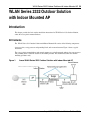
WLAN Series 2332 Outdoor Solution
with Indoor Mounted AP
Introduction
This chapter provides the basic outdoor installation instructions for WLAN Series 2332 Outdoor Solution,
where the access point is mounted indoors.
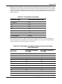
Kit Contents
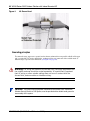
The WLAN Series 2332 Outdoor Solution with Indoor Mounted AP consists of the following components:
An access point, a surge protector and grounding block, and an external antenna. Figure 1 shows a typical
installation.
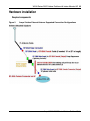
The access point is mounted indoors and external antennas are typically mounted outdoors, the surge protector
and grounding block is installed outdoors at the building entrance. This document describes the solution
mounting procedures only.
Figure 1.
Avaya WLAN Series 2332 Outdoor Solution with Indoor Mounted AP
Avaya WLAN 2332 Series Outdoor Solution Guide
40 WLAN Series 2332 Outdoor Solution with Indoor Mounted AP
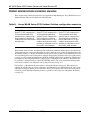
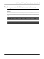
Package contents
Table 7.
Avaya WLAN Series 2332 Outdoor Solution kits for AP
InstalledoIndoors Outdoor Solution Kits for
Part
Number
Kit Components
DR4011019E5
Phase I Outdoor
starter bundle
Surge
suppressor
Coax-Seal tape
10 ft RoHS
Plenum rated
coax cable
1- Male
RSMA
connector
1- Female
RSMA
connector
DR400085E5
Surge suppressor
Surge
suppressor
Coax-Seal tape
Documentation
DR4018006E5
10 ft. Coax
extension
10 ft RoHS
Outdoor rated
coax cable
Coax seal tape
1- Female
RSMA
connector
1- Male
RSMA
connector
Documentation
DR4018007E5
25 ft. Coax
extension
25 ft RoHS
Outdoor rated
coax cable
Coax seal tape
1- Female
RSMA
connector
1- Male
RSMA
connector
Documentation
NN47250-506 (324883-B Rev 02 Version 02.02)
Documentation
WLAN Series 2332 Outdoor Solution with Indoor Mounted AP 41
Basic outdoor installation information
Signal path distance
In an environment without obstacles in the signal path, the maximum communication distance between
antennas depends primarily on the types of antennas, the operating frequency, the data rate and the free space
loss between them. Make sure your proposed mounting site provides adequate clearance around the
transmitting antenna to enable adequate signal propagation. The WLAN Series 2332 Outdoor Solution
supports data rates up to 54 Mbps.
Signal attenuation and loss in outdoor installations
“Appendix” on page 69
Antenna polarization
“Appendix” on page 69
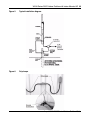
Signal path clearance
A radio beam is intended to travel from one antenna to another in a direct path. Therefore, the path between the
antennas must be free of major obstacles. The effects of obstacles and terrain, both along and near the path,
have a significant bearing on the propagation of radio signals and can cause both interference and signal
degradation.
When choosing a site, consider the effects of the following common obstacles:
• Trees and large plants
A tree directly in the path can completely block the signal. With sufficient clearance above the trees there are
usually no secondary effects, but you should allow for future tree growth.
• Man-made obstacles
A large round container such as a gas storage reservoir or water tower that is partially in the path causes some
blocking. These obstacles may also reflect some energy, which can interfere with other receivers. Square or
rectangular objects in or near the path have rectangular surfaces that can block and diffract signals over and
around them.
• Earth surface
The earth surface also interferes with signals if the antenna is mounted too low. Mount the antenna just high
enough to allow adequate clearance from the ground. Placing the antenna too high makes it susceptible to
interference from other systems.
Physical site survey
Perform a visual inspection of the site to determine and document the physical characteristics of the site and to
ensure that all requirements are met for the proper installation and operation of the system.
Avaya WLAN 2332 Series Outdoor Solution Guide
42 WLAN Series 2332 Outdoor Solution with Indoor Mounted AP
Contact information and access permissions
Make sure the following general requirements are met before beginning the installation:
• Confirm customer-provided information, such as site contact names and telephone numbers.
• Examine the building (tenant) lease to verify or establish building roof or tower rights. If available, use
layout drawings to evaluate the feasibility of modifications or special permits that might be necessary.
• For a tower-mounted installation, find out if the owner, operator, or landlord requires a professional or
certified tower climber to do the work.
Physical site
Make sure the following physical site requirements are met before beginning the installation:
• Identify the roof area, wall, or tower for mounting the antenna. You must choose a site with a clear
line-of-sight from the transmitting antenna.
• Determine the access area, such as a stairway or a ladder.
• Identify existing equipment installations and assess the condition of proposed towers or mounting structures.
• Assess environmental conditions, such as temperature, ventilation, and humidity.
Warning! Install this device in such a manner as to maintain a minimum of 20
cm (7.9 inches) separation distance between the radiating element(s) and all
persons. This safety warning conforms with FCC radio frequency exposure limits.
Warning! Intentional radiators, such as the Avaya WLAN Series 2332 Access
Points are not intended to be operated with any antenna(s) other than those
furnished by . An intentional radiator may only be operated with the antenna(s)
with which it is authorized. For a complete listing of the authorized antennas for
use with this product, visit http://www.avaya.com/support.
Caution! Do not install the outdoor antenna or connect it to the surge
suppressor/Access Point during a storm.
NN47250-506 (324883-B Rev 02 Version 02.02)
WLAN Series 2332 Outdoor Solution with Indoor Mounted AP 43
Hardware installation
Required components
Figure 2.
Avaya Outdoor External Antenna Supported Connection Configurations
Avaya WLAN 2332 Series Outdoor Solution Guide
44 WLAN Series 2332 Outdoor Solution with Indoor Mounted AP
Outdoor external antenna connection scenarios
There are three basic connection scenarios that are supported for implementing the Avaya WLAN Series 2332
Outdoor Solution. These are described in the following table:
Table 8.
Avaya WLAN Series 2332 Outdoor Solution configuration scenarios
Scenario 1
Scenario 2
Scenario 3
Configuration consists of the
Series 2332 AP connected to a
10-foot plenum rated cable,
which in turn is connected to a
Surge Suppressor and then is
connected to one of the outdoor
rated antennas
Configuration consists of the
Series 2332 AP connected to a
10-foot plenum rated cable,
which in turn is connected to a
Surge Suppressor, which in
turn is connected to a 10-foot
outdoor rated extension cable
and then is connected to one of
the outdoor rated antennas.
Configuration consists of the
Series 2332 AP connected to a
10-foot plenum rated cable,
which in turn is connected to a
Surge Suppressor, which in
turn is connected to a 25-foot
outdoor rated extension cable
and then is connected to one of
the outdoor rated antennas.
Based on these three scenarios, the following tables illustrate the additional amount of power loss that will be
realized when the extra cables and components are used to enable the access point to be mounted indoors and
the radiating element (i.e. antenna) to be mounted on the exterior of the premises. These additional losses need
to be factored into the overall system path loss equation when selecting placement of the access points and net
coverage areas. The current implementation of the WSS and WMS software does not allow for optimization of
performance by increasing the transmitter's output power to compensate for the added loss. That feature will
be available in a subsequent release of the WSS and WMS software. The values listed in the following tables
can be used to estimate a net reduction in total system power and coverage area.
For reference, a 3 dB reduction in power equates to halving the effective linear power. This translates to a
reduction in available range of a factor of four times. An additional loss of 3 dB would halve the power again
and reduce the range by another factor of four times. Hence, care should be taken to place the access point as
near to the point of debarkation from the premises as possible to reduce signal loss and optimize the outdoor
coverage area.
NN47250-506 (324883-B Rev 02 Version 02.02)
WLAN Series 2332 Outdoor Solution with Indoor Mounted AP 45
Table 9.
Loss associated with 10-foot plenum rated cable and surge
suppressor Loss associated Surge a
Connects AP
to Surge
Suppressor
Plenum Rated Cable (RG-58)
Component
10 ft Cable
Frequency
(MHz)
Loss (dB)
2400 - 2500
5150 - 5250
Surge Suppressor
10 ft Cable + Surge
Suppressor
Loss (linear)
Loss (dB)
Loss (linear)
Loss (dB)
Loss (linear)
-2.89
0.486
-0.13
0.029
-3.02
0.501
-4.96
0.681
-0.40
0.087
-5.36
0.709
5250 - 5350
-5.00
0.684
-0.38
0.083
-5.38
0.710
5470 - 5725
-5.23
0.700
-0.47
0.103
-5.70
0.731
5725 - 5850
-5.30
0.705
-0.57
0.123
-5.87
0.741
Avaya WLAN 2332 Series Outdoor Solution Guide
46 WLAN Series 2332 Outdoor Solution with Indoor Mounted AP
Table 10. Loss associated with 10-foot and 25-foot outdoor rated extension
cables Loss associated with 10-
Connects surge
suppressor to
Antenna
Outdoor Cable (LMR-240)
Component
10 ft Cable
Frequency
(MHz)
Loss (dB)
Loss (linear)
Loss (dB)
Loss (linear)
2400 - 2500
-1.84
0.345
-3.89
0.591
5150 - 5250
-2.68
0.460
-5.70
0.731
5250 - 5350
-2.79
0.474
-5.81
0.737
5470 - 5725
-2.78
0.473
-5.91
0.743
5725 - 5850
-2.81
0.476
-5.93
0.745
25 ft Cable
The following table summarizes the net effective loss for the three connection scenarios outlined above. In
general, for the 2.4 GHz operating frequency band, Scenario 1 will have an additional loss of 3.0 dB, Scenario
2 will have an additional loss of 4.9 dB and Scenario 3 will add a loss of 6.9 dB.
Table 11. Summary of loss for three scenarios
Outdoor Combinations
Configuration
Scenario 1
Scenario 2
Scenario 3
Frequency
(MHz)
Loss (dB) Loss (linear) Loss (dB) Loss (linear) Loss (dB) Loss (linear)
2400 - 2500
-3.02
0.501
-4.86
0.673
-6.91
0.796
5150 - 5250
-5.36
0.709
-8.04
0.843
-11.06
0.922
5250 - 5350
-5.38
0.710
-8.17
0.847
-11.18
0.924
5470 - 5725
-5.70
0.731
-8.48
0.858
-11.61
0.931
5725 - 5850
-5.87
0.741
-8.68
0.865
-11.81
0.934
Surge suppressor (lightning arrestor)
The series gas-discharge surge suppressors (lightning arresters) provide high-level protection for transmitters
and receives at RF-communication sites. In the event of a local strike, the unit’s gas discharge tube ionizes
instantaneously to limit sudden voltage surges across the coaxial line. When connected to a satisfactory
ground, the unit can safely shunt up to 5000 Amps of impulse current away from sensitive station equipment.
NN47250-506 (324883-B Rev 02 Version 02.02)
WLAN Series 2332 Outdoor Solution with Indoor Mounted AP 47
Warning! A properly rated surge suppressor is required for any
cable/antenna combination exiting the building. The required components must
be rated and approved for use in the intended application.
Figure 3.
Surge suppressor
Installation
For best results, install the surge suppressor in close proximity to a low-resistance ground at a point where the
coaxial cable enters the building. In most cases, one 8-foot rod driven into moist soil or multiple rods bonded
together will provide adequate grounding. (see National Electrical Code guidelines).
Install the surge suppressor in an accessible location that allows for periodic inspection and possible
replacement of the gas cartridge. Provide drip loops in the cables to prevent water from entering the building,
see (Figure 6 on page 49).
The life expectancy of the replaceable gas tube depends on the frequency and severity of electrostatic activity
at the site. Low-level conduction resulting from near-by storm activity has very little impact on the life of the
cartridge, but powerful surges induced by on-site strikes will eventually result in degraded performance or
failure. Degraded performance indicators include reduced receiver sensitivity, above normal VSWR readings,
and RF heating of the surge suppressor body during transmit mode. Should the discharge tube fail totally, it
becomes a permanently conductive protective shunt to ground. Periodic SWR checks provide a good indicator
of deteriorating performance, and routine replacement may be indicated following especially severe weather
events where multiple on-site strikes were known to have happened.
Avaya WLAN 2332 Series Outdoor Solution Guide
48 WLAN Series 2332 Outdoor Solution with Indoor Mounted AP
Figure 4.
#8 Ground lead
Grounding principles
To connect the surge suppressor to ground, use the shortest and most direct run possible with #8 solid copper
wire (or equivalent). For exterior installations, weatherproof the coax connectors with a suitable mastic or
rubberized tape to prevent water infiltration. (see Figure 4 on page 48).
Warning! All wiring and cables to the Access Point, the surge suppressor and
the outdoor antenna should be routed separately. It is particularly important
that AC wiring or other outside cabling does not come in contact with the
Access Point, antenna cables or interface wiring.
Caution! The power source equipment connected to the Access Point, such as the
Wireless Security Switch or PoE injector, must be provided with a reliable earth ground to
insure safety of the system.
NN47250-506 (324883-B Rev 02 Version 02.02)
WLAN Series 2332 Outdoor Solution with Indoor Mounted AP 49
Figure 5.
Typical installation diagram
Figure 6.
Drip Loops
Avaya WLAN 2332 Series Outdoor Solution Guide
50 WLAN Series 2332 Outdoor Solution with Indoor Mounted AP
Note. A good ground system is essential for proper operation.
Warning! A properly rated surge suppressor is required for any
cable/antenna combination exiting the building. The required components must
be rated and approved for use in the intended application.
Outdoor external antennas
This section introduces the outdoor external antenna portfolio available for the WLAN Series 2332 Access
Points. The portfolio includes 802.11b/g (2.4 GHz) and 802.11a (5.0 GHz) models for outdoor use. The
addition of outdoor external antennas to the WLAN Series 2332 System portfolio improves overall system
value:
• Improved deployment flexibility - Planners can choose an antenna pattern that meets coverage requirements
while allowing for convenient AP placement and installation.
• Improved coverage and performance - External antennas allow planners to optimize coverage and deliver
higher available data rates to user concentrations.
• Can provide a low cost fix for trouble spots - Appropriately outfitting existing APs with external antennas
can greatly improve coverage and available data rates in areas that are not adequately serviced.
• Lower cost of coverage - External antennas improve overall system efficiency by effectively directing
available energy to where it's needed. This ensures overall system utility is maximized for any installation.
The WLAN Series 2332 outdoor external antennas are the only external antennas certified by for use with
WLAN Series 2332 systems. WLAN Series 2332 Access Points that are outfitted with non-certified outdoor
external antennas are not supported under support agreements.
The WLAN Series 2332 system must be upgraded to WSS Software Release 6.0.6.2 or later and WMS
Software Release 6.0.7.1 or later. This upgrade includes antenna pattern libraries for the WLAN Series 2332
outdoor external antenna portfolio and allows the system to:
• Compensate for extension cable loss and lightning protection circuitry that is essential for operation in an
outdoor environment.
• Correctly interpret received signal strength measurements from APs with external antennas when calculating
rogue device or client location.
The WLAN Series 2332 System outdoor external antenna portfolio is sourced from Cushcraft, a world leader
in the development of advanced antenna technology and products.
• The Cushcraft products have been modified for compatibility with the Series 2332 Access Points
• versions are equipped with an R-SMA type connector to comply with 's quality and regulatory standards and
correctly interface with the Series 2332 Access Points.
• The Cushcraft model numbers presented throughout this bulletin refer to the specific versions and may not
exactly match similar versions promoted on Cushcraft's website or other product materials.
NN47250-506 (324883-B Rev 02 Version 02.02)
WLAN Series 2332 Outdoor Solution with Indoor Mounted AP 51
• has tested and measured each product. The antenna gains expressed in dBi measurements are the tested
values and may differ slightly from those published by Cushcraft for similar products.
Coax cable seal installation
Applying coax seal tape
You must weather seal all outside coaxial connections using the coax seal tape provided in the mounting kit.
Coax connections that are not properly sealed permit moisture to enter the connection, which leads to
performance degradation or link problems.
Note. Do not use plastic or vinyl electrical tape on the connectors because it will
deteriorate during long-term exposure to ultraviolet light and extreme weather.
To apply the coax seal tape, follow these steps:
1
Make sure that the coaxial cables, connectors, and the connector area are clean and dry.
2
Peel the paper backing from a length of coax seal tape.
3
Wrap each connector with the coax seal tape, starting at the coaxial cable, extending across the connector
body, and finishing close the lightning arrestor surge suppressor or grounding block. Overlap each turn at
least 50 percent so there is a double thickness over all areas. See Figure 7 on page 51.
Figure 7.
Applying the coax seal tape before smoothing.
Use your fingers to mold and form the coax seal tape around the cable and connector to form a smooth, neat
surface. Be sure to squeeze out any air pockets. See Figure 8 on page 52
Avaya WLAN 2332 Series Outdoor Solution Guide
52 WLAN Series 2332 Outdoor Solution with Indoor Mounted AP
Figure 8.
Coax seal tape after smoothing.
4
Visually inspect the seal to make sure the entire connector area is completely covered. If you find gaps,
apply additional Coax-Seal over the existing material and then mold it to shape
5
Repeat these steps for each coaxial connection outside.
Physical site survey
Perform a visual inspection to determine and document the physical characteristics of the site and to ensure
that all requirements are met for the proper installation and operation of the system.
Physical site
Make sure the following requirements for your physical site are met before beginning the installation:
• Identify the roof area, wall, or tower for mounting the solution. You must choose a site with a clear
line-of-sight from the transmitting antenna.
• Determine the access area, such as a stairway or a ladder.
• Identify existing equipment installations and assess the condition of proposed towers or mounting structures.
Assess environmental conditions, such as temperature, ventilation, and humidity.
Cable routes
Make sure the following cable route requirements are met before beginning the installation:
• Determine cable routes, building entry points, and any special routing or support requirements (conduits,
bracing, cable trays, safety structures, and so on). Make sure the total cable length between the access point
and the wireless security switch is no greater than 100 meters.
• Identify necessary floor, roof, or wall penetrations and specify the locations.
• Document existing grounding system and connection requirements for new equipment.
• Refer to these electrical codes for your local regulations:
NFPA 70 (US National Electrical Code)
Canadian Electrical Code, Part1, CSA 22.1
IEC 364, Part 1 through 7 for other countries
NN47250-506 (324883-B Rev 02 Version 02.02)
WLAN Series 2332 Outdoor Solution with Indoor Mounted AP 53
Software installation
Country of operation
Before you can configure APs and radio parameters, you must specify the country in which you plan to operate
the radios. Since each country has different regulatory environments, the country code determines the transmit
power levels and channels you can configure on the radios. WSS software ensures that the values you can
configure are valid for the country you specify.
You must specify the country in which you plan to operate the WSS and its APs. WSS software does not allow
you to configure or enable the AP radios until you specify the country of operation
The country code is one of the parameters you set when you create a network plan. Be sure to select the
country code for the country in which the AP will be operated. It is a violation of regulatory laws to set the
country code to a country that is different than the actual country in which the AP is operating.
For a complete listing of the two-letter country codes, refer to the "Approved Countries for the WLAN Series
2332 Components" at http://www.avaya.com/support.
Use of external antenna configuration option CLI and WMS
Specifying the external antenna model
To specify the 2.4 GHz external antenna model using CLI, use the following command:
set {ap port-list | dap dap-num} radio {1 | 2} antennatype {internal | 24143 | 24123 | 24113 |
24203 | 24403 | 24453 | 24493 | 24553 | 24883 | mixed | 24143-OUT | 24143-OUT-10 |
24143-OUT-25 | 24143-NEMA | 24143-NEMA-10 | 24143-NEMA-25 | 24123-OUT |
24123-OUT-10 | 24123-OUT-25 | 24123-NEMA | 24123-NEMA-10 | 24123-NEMA-25 |
24113-OUT | 24113-OUT-10 | 24113-OUT-25 | 24113-NEMA | 24113-NEMA-10 |
24113-NEMA-25 | 24493-OUT | 24493-OUT-10 | 24493-OUT-25 | 24493-NEMA |
24493-NEMA-10 | 24493-NEMA-25 | 24883-OUT | 24883-OUT-10 | 24883-OUT-25 |
24883-NEMA | 24883-NEMA-10 | 24883-NEMA-25}
Avaya WLAN 2332 Series Outdoor Solution Guide
54 WLAN Series 2332 Outdoor Solution with Indoor Mounted AP
To specify the 5.0 GHz external antenna model using CLI, use the following command:
set {ap port-list | dap dap-num} radio {1 | 2} antennatype {internal | 5133 | 5303 | 5643 | 5173 |
5103 | mixed | 5133-OUT | 5133-OUT-10 | 5133-OUT-25 | 5133-NEMA | 5133-NEMA-10 |
5133-NEMA-25 | 5643-OUT | 5643-OUT-10 | 5643-OUT-25 | 5643-NEMA |
5643-NEMA-10 | 5643-NEMA-25 | 5173-OUT | 5173-OUT-10 | 5173-OUT-25 |
5173-NEMA | 5173-NEMA-10 | 5173-NEMA-25 | 5103-OUT | 5103-OUT-10 |
5103-OUT-25 | 5103-NEMA | 5103-NEMA-10 | 5103-NEMA-25}
Note. The options displayed are dependent upon the access point model number that
this CLI command is executed against. The following example is for an Access point
2332-A1.
To configure antenna model 5643-OUT-10 for a 2332-A1 on Distributed AP 1, type the following command:
WSS# set dap 1 radio 1 antennatype 5643-OUT-10
success: change accepted.
To specify the external antenna model using WMS, use the AP Configuration menu and fill in the required
information.
NN47250-506 (324883-B Rev 02 Version 02.02)
WLAN Series 2332 Outdoor Solution with Indoor Mounted AP 55
Figure 9.
WMS AP external antenna configuration
Avaya WLAN 2332 Series Outdoor Solution Guide
56 WLAN Series 2332 Outdoor Solution with Indoor Mounted AP
Other related documentation references
•
WLAN—Management System 2300 Series Reference Manual. Instructions for planning, configuring,
deploying, and managing the entire WLAN with the WLAN Management System tool suite
•
WLAN—Security Switch 2300 Series Configuration Guide. Instructions for configuring and managing the
system through the WSS software CLI
•
WLAN—Security Switch 2300 Series Command Line Reference. Functional and alphabetic reference to all
WSS software commands supported on WSSs and APs
•
WLAN—Series 2332 Access Point Installation Guide. Instructions for planning, configuring, deploying, and
managing the access points.
NN47250-506 (324883-B Rev 02 Version 02.02)
WLAN Series 2332 Outdoor Solution with AP Mounted in NEMA Enclosure 57
WLAN Series 2332 Outdoor Solution
with AP Mounted in NEMA Enclosure
Introduction
This chapter provides the NEMA Enclosure Installation Instructions for the WLAN Series 2332 Outdoor
Solution, where the AP is mounted outdoors.
Figure 10.
Avaya WLAN Series 2332 Outdoor Solution
Kit Contents for Series 2332 AP installed outdoors in NEMA Enclosure
The kit consists of the following components:
• Series 2332 Access Point in separate box
• ODS NEMA enclosure
• Ethernet lightning Surge Suppressor
• Installation document
Avaya WLAN 2332 Series Outdoor Solution Guide
58 WLAN Series 2332 Outdoor Solution with AP Mounted in NEMA Enclosure
Figure 11.
Kit Contents of the NEMA Outdoor Solution
Site Planning
Perform a visual inspection to determine and document the physical characteristics of the site.
Ensure that the Site Planning meets the following requirements before you begin the installation:
• Identify the roof area, wall, or tower for mounting the Outdoor Solution.
• Choose a site with a clear line-of-sight from the transmitting antenna.
• Determine the access area, such as a stairway or a ladder.
• Identify existing equipment installations and assess the condition of proposed towers or mounting structures.
• Assess environmental conditions, such as temperature, ventilation, and humidity.
Ethernet
The AP must be <100 meters from the WSS (WLAN Security Switch).
Note. Avaya recommends using outdoor CAT5E Ethernet Cable for all external connections.
Antenna
Ensure that antennas have advanced deployment flexibility, coverage, and performance.
This implies that planners should choose:
• An antenna pattern that meets coverage requirements while allowing for convenient AP placement and
installation.
• Antennas that optimize the coverage pattern and deliver higher available data rates to user concentrations.
NN47250-506 (324883-B Rev 02 Version 02.02)
WLAN Series 2332 Outdoor Solution with AP Mounted in NEMA Enclosure 59
• Coverage pattern and available data rates in areas that are not adequately serviced.
• Overall system efficiency by effectively directing available energy to where it's needed.
• System utility for any installation.
The WLAN Series 2332 outdoor external antennas are the only external antennas certified by Avaya for use
with WLAN Series 2332 systems. WLAN Series 2332 Access Points that are outfitted with non-certified
outdoor external antennas are not supported under Avaya support agreements.
The WLAN Series 2332 system must be upgraded to WSS Software 6.0.6.2 or later and WMS 6.0.7.1 or later.
This upgrade includes antenna pattern libraries for the WLAN Series 2332 outdoor external antenna portfolio
and allows the system to:
• Compensate for extension cable loss and lightning protection circuitry that is essential for operation in an
outdoor environment.
• Correctly interpret received signal strength measurements from APs with external antennas when calculating
rogue device or client location.
The WLAN Series 2332 System outdoor external antenna portfolio is sourced from Cushcraft, a world leader
in the development of advanced antenna technology and products.
• The Cushcraft products have been modified for compatibility with the Series 2332 Access Points.
• Avaya versions are equipped with an R-SMA type connector to comply with Avaya's quality and regulatory
standards and correctly interface with the Series 2332 Access Points.
• The Cushcraft model numbers presented throughout this bulletin refer to the Avaya specific versions and
may not exactly match similar versions promoted on Cushcraft's website or other product materials.
• Avaya has tested and measured each product. The antenna gains expressed in dBi measurements are the
Avaya tested values and may differ slightly from those published by Cushcraft for similar products.
Note. Only use Avaya approved antennas with the Series 2332 Access Points.
Safety Precautions
In this section Powerline and Installation safety precautions are provided.
Powerline
• Coming in contact with power lines can be lethal.
• Ensure that there are no accessible power lines near the installation site to avoid accidental or incidental
human contact with these lines.
• Ensure that antennas, masts, towers, guy wires or cables cannot come into contact with these powerlines. Try
to plan for potential leaning or falling of this equipment into these lines.
• You may get injured or killed if you are touching or holding any part of equipment when it contacts electric
power lines.
• Ensure there is NO possibility that equipment or personnel can come in contact directly or indirectly with
power lines.
Avaya WLAN 2332 Series Outdoor Solution Guide
60 WLAN Series 2332 Outdoor Solution with AP Mounted in NEMA Enclosure
• If anything, such as a wire or mast, does come in contact with a powerline, DO NOT TOUCH IT OR
ATTEMPT TO MOVE IT. Call the power company.
• Do not attempt to errect antennas or towers on windy days.
Installation
• The horizontal distance from a tower, mast or antenna to the nearest power line should be at least twice the
total length of the mast/antenna combination. This will ensure that the mast will not contact the power line if
it falls either during installation or later.
• Make sure that all towers and masts are securely grounded and electric cables connected to antennas have
lightning protection. This will help to prevent fire damage or human injury in case of lightning, static
build-up, or short circuit when equipment is connected to the antenna.
Heat/Cold loading
The NEMA Enclosure environment must not exceed the operating specifications for the AP (Series 2332).
Temperature must be between 0 to 50 degrees C and humidity between 10 to 95%, non condensing.
Reference Information
The following section describes the Ethernet Lightning Surge Protector, Terminal Strip Connection, Coax
cable seal Installation, and Antennas.
Ethernet and Antenna Lightning Surge Protector
The Avaya series gas-discharge Antenna surge Protector (lightning protector) provides high-level protection
for transmitters and receivers at RF-communication sites. In the event of a local strike, the unit’s gas discharge
tube ionizes instananeously to limit sudden voltage surges across the coaxial line. When connected to a
satisfactory ground, the unit can safely shunt up to 5000 Amps of impulse current away from sensitive station
equipment.
Warning! A rated surge Protector is required for any cable/antenna combination exiting the
building. The required components must be rated and approved for use in the intended
application.
Installation
The Ethernet Lightning Surge Protector is mounted close to the building entrance. The cables must enter the
building through customer provided access, possibly through the drilled hole where there are communications
pipes.
For better results, install the Lightning Surge Protector in close proximity to a low-resistance ground at a point
where the Ethernet cable enters the building. In most cases, one 8-foot rod driven into moist soil or multiple
rods bonded together will provide adequate grounding.
Install the Lightning Surge Protector in an accessible location that allows for periodic inspection. Provide drip
loops in the cables to prevent water from entering the building.
NN47250-506 (324883-B Rev 02 Version 02.02)
WLAN Series 2332 Outdoor Solution with AP Mounted in NEMA Enclosure 61
Grounding principles
To connect the Surge Protector to ground, use the shortest and most direct run possible with #8 solid copper
wire (or equivalent).
Refer to your local electric code standards for correct installation.
Applying coax seal tape
For applying Coax seal tape refer:
See “Coax cable seal installation” page 51
Installation of Series 2332 Access Points
In this section you will find instructions on installing the Series 2332 Access Points in an outdoor mounted
enclosure.
Installation of the NEMA Enclosure
1
Figure 12.
2
Remove the NEMA Enclosure from the ODS kit and place it on a flat surface near the installation
location. The following figure shows the enclosure connections from left to right: ground lug, Ethernet
Gland, and two external antenna connectors.
NEMA Enclosure
Open the enclosure cover by pushing the latches down on the side and lifting the cover up.
Avaya WLAN 2332 Series Outdoor Solution Guide
62 WLAN Series 2332 Outdoor Solution with AP Mounted in NEMA Enclosure
Figure 13.
External Antenna cables in the Enclosure
3
Obtain the AP mounting bracket from the AP kit.
4
Use two 6/32 screws to secure the mounting bracket to the standoffs in the enclosure as shown in
Figure 14
Figure 14.
Mounting Bracket
5
Unscrew the Ethernet Gland nut on the outside of the enclosure.
6
Remove the split rubber washers from the Ethernet Gland nut.
7
Slide the Ethernet Gland nut onto the Ethernet cable.
Make sure the threaded end is facing the Ethernet cable connector on the enclosure.
8
Slide the rubber washers onto the Ethernet cable.
The rubber washers and gland nut on the Ethernet cable are shown in Figure 15 .
NN47250-506 (324883-B Rev 02 Version 02.02)
WLAN Series 2332 Outdoor Solution with AP Mounted in NEMA Enclosure 63
Figure 15.
9
Rubber Washers into the Ethernet cable
Insert enough of the Ethernet cable into the enclosure so that you can connect it to the AP.
10 Tighten the Gland nut, but not 100%. Tighten it just enough to ensure it stays in place.
11 Loop the Ethernet cable through the mounting bracket as shown in Figure 16 .
Figure 16.
Ethernet cable in the Mounting Bracket
12 Connect the Ethernet cable to Port 1 on the AP as shown in Figure 17
Avaya WLAN 2332 Series Outdoor Solution Guide
64 WLAN Series 2332 Outdoor Solution with AP Mounted in NEMA Enclosure
Figure 17.
Connecting Ethernet cable to Port 1
13 Connect the external antenna cables to the AP as shown in Figure 18 .
11A Antenna cable connects to top connector.
11BG Antenna cable connects to bottom connector.
Figure 18.
Connecting external antenna cables to the AP
14 Use a 5/16 wrench to tighten the external antenna connectors to the recommended specifications.
NN47250-506 (324883-B Rev 02 Version 02.02)
WLAN Series 2332 Outdoor Solution with AP Mounted in NEMA Enclosure 65
Note. Be careful not to over-tighten the coaxial cable connections. Damage to the AP may result if too
much torque is applied to the connection.
15 Attach AP to the AP mounting bracket.
16 From AP side opposite of Antenna connections, find location to lock Mounting plate.
For more information about Installation of Mounting Plate, refer to the Avaya WLAN Series 2332 Access
Point Installation Guide.
17 Use AP mounting tool(nail) to lock the AP to the bracket.
18 Secure Cover on the enclosure.
19 Complete tightening of the Ethernet Gland nut.
20 Mount the NEMA enclosure with appropriate mounting hardware that supports the ODS NEMA
Enclosure.
21 Ground the enclosure by attaching the ground cable to the ground lug according to Local Electrical Code.
22 Attach external antennas to NEMA Enclosure with Avaya approved cable.
Installation of the Ethernet Lightning Surge Protector
1
Obtain the Ethernet Lightning Surge Protector from the Kit.
2
Remove the cover of the Ethernet Lightning Surge Protector.
3
Unscrew the Ethernet Gland nut on the left side of the Ethernet Lightning Surge Protector.
4
Remove the rubber washers from the Ethernet Gland.
5
Slide the Ethernet Gland nut onto the Ethernet cable.
Make sure the threaded end is facing the Ethernet cable connector on the enclosure.
6
Slide the rubber washers onto the Ethernet cable.
7
Insert the Ethernet cable into the Ethernet Lightning Surge Protector and connect it to the connector
labeled LINE as shown in Figure 19 .
Avaya WLAN 2332 Series Outdoor Solution Guide
66 WLAN Series 2332 Outdoor Solution with AP Mounted in NEMA Enclosure
Figure 19.
Connecting Ethernet Lightning Surge Protector to the Connector
8
Tighten the Ethernet Gland nut.
9
Connect the Ethernet cable to the WLAN Security Switch (WSS).
10 Unscrew the Ethernet Gland nut on the right side of the Ethernet Lightning Surge Protector.
11 Remove the rubber washers from the Ethernet Gland.
12 Slide the Ethernet Gland nut onto the Ethernet cable.
Make sure the threaded end is facing the Ethernet cable connector on the enclosure.
13 Slide the rubber washers onto the Ethernet cable.
14 Connect the Ethernet cable to the Ethernet Lightning Protector connector labeled EQUIP.
15 Tighten the Ethernet Gland nut.
16 Replace the cover of the Ethernet Lightning Surge Protector.
17 Mount the Ethernet Lightning Surge Protector with the appropriate hardware available in the kit.
Refer to the Mounting instructions in the box.
For more Information about the Mounting of the Ethernet Surge Protector refer Appendix.See “Surge
suppressor (lightning arrestor)” page 46
18 Ground Ethernet Lightning Surge Protector by attaching Ground cable to Ground lug according to local
electric code
Terminal Strip Connection
You can use terminal strips if you do not have RJ 45 jack connectors.
To use Terminal Strip perform the following steps:
1
Install the data cable through the strain relief.
NN47250-506 (324883-B Rev 02 Version 02.02)
WLAN Series 2332 Outdoor Solution with AP Mounted in NEMA Enclosure 67
2
Strip back cable jackets.
3
Terminate the data wires to the screw down terminal blocks.
To pin out the Terminal strips refer Figure 20 .
Figure 20.
Terminal Strip Connection
Warning! Avaya requires that the Access Point in the outdoor enclosure be powered with a
Power Over Ethernet (POE) that is supplied only from an Avaya WSS 2350 or WSS 2360/2361
wireless security switch.
Software
Country of operation
Before you can configure APs and radio parameters, you must specify the country in which you plan to operate
the radios. Since each country has different regulatory environments, the country code determines the transmit
power levels and channels you can configure on the radios. WSS Software ensures that the values you can
configure are valid for the country you specify.
You must specify the country in which you plan to operate the WSS and its APs. WSS Software does not allow
you to configure or enable the AP radios until you specify the country of operations.
The country code is one of the parameters you set when you create a network plan. Be sure to select the
country code for the country in which the AP will be operated. It is a violation of regulatory laws to set the
country code to a country that is different than the actual country in which the AP is operating.
For a complete listing of the two-letter country codes, refer to the "Approved Countries for the WLAN Series
2332 Components" at http://www.avaya.com/support.
To specify the 2.4 GHz external antenna model using CLI, use the following command:
Avaya WLAN 2332 Series Outdoor Solution Guide
68 WLAN Series 2332 Outdoor Solution with AP Mounted in NEMA Enclosure
set {ap port-list | dap dap-num} radio {1 | 2} antennatype {internal | 24143 | 24123 | 24113 | 24203 | 24403 |
24453 | 24493 | 24553 | 24883 | mixed | 24143-OUT | 24143-OUT-10 | 24143-OUT-25 | 24143-NEMA |
24143-NEMA-10 | 24143-NEMA-25 | 24123-OUT | 24123-OUT-10 | 24123-OUT-25 | 24123-NEMA |
24123-NEMA-10 | 24123-NEMA-25 | 24113-OUT | 24113-OUT-10 | 24113-OUT-25 | 24113-NEMA |
24113-NEMA-10 | 24113-NEMA-25 | 24493-OUT | 24493-OUT-10 | 24493-OUT-25 | 24493-NEMA |
24493-NEMA-10 | 24493-NEMA-25 | 24883-OUT | 24883-OUT-10 | 24883-OUT-25 | 24883-NEMA |
24883-NEMA-10 | 24883-NEMA-25}
To specify the 5.0 GHz external antenna model using CLI, use the following command:
set {ap port-list | dap dap-num} radio {1 | 2} antennatype {Internal | 5133 | 5303 | 5643 |5173 | 5103 | mixed
| 5133-OUT | 5133-OUT-10 | 5133-OUT-25 | 5133-NEMA | 5133-NEMA-10 | 5133-NEMA-25 | 5643-OUT |
5643-OUT-10 | 5643-OUT-25 | 5643-NEMA | 5643-NEMA-10 | 5643-NEMA-25 | 5173-OUT | 5173-OUT-10
| 5173-OUT-25 | 5173-NEMA | 5173-NEMA-10 | 5173-NEMA-25 | 5103-OUT | 5103-OUT-10 |
5103-OUT-25 | 5103-NEMA | 5103-NEMA-10 | 5103-NEMA-25}
Note. The options displayed are dependent upon the access point model number that this CLI command is
executed against. The following example is for a 2332-A1 Access Point.
To configure antenna model 5643-OUT-10 for a 2332-A1 on Distributed AP 1, type the following command:
WSS# set dap 1 radio 1 antennatype 5643-OUT-10
To specify the external antenna model using WMS, use the AP Configuration menu and fill in the required
information refer Figure 21 .
Figure 21.
Configuring an Antenna
NN47250-506 (324883-B Rev 02 Version 02.02)
Appendix 69
Appendix
Supported antenna information
Outdoor external antenna options
The outdoor external antenna WSS model string relates directly to the base external antenna being used in the
connection scenarios outlined previously.
For example, WSS model string 24493-OUT would imply a configuration that includes the 10-foot
plenum-rated R-SMA (M) to R-SMA (F) indoor RoHS compliant cable, the surge suppressor (DR4000085E5)
and the S2403BPXN36RSM antenna (DR4000088E6). Additionally, WSS model string 24493-OUT-10 would
include the 10-foot plenum-rated R-SMA (M) to R-SMA (F) indoor RoHS compliant cable, the lightning
arrester (DR4000085E5), the 10-foot R-SMA (F) to R-SMA (M) OUTDOOR LMR-240, RoHS compliant
cable (DR4018006E5) and the S2403BPXN36RSM antenna (DR4000088E6).
The following table lists the outdoor accessories associated with constructing the connection scenarios
outlined previously:
Table 12: Outdoor accessories
Cushcraft P/N
Avaya P/N
Description
LAC6NRSMMF
DR4000085E5
Surge suppressor (Lightning
Arrestor) with coaxial seal tape.
Connectors: R-SMA female input
and R-SMA male output.
CANRSM120TRSMF
323843-A (N0152955)
10' plenum-rated R-SMA (M) to
R-SMA (F) INDOOR LMR-195,
RoHS compliant cable. Cannot
order separately. Included in
DR4011019E5.
CANRSM120WRSMF
DR4018006E5
10' outdoor R-SMA (F) to R-SMA
(M) (OUTDOOR LMR-240,
RoHS compliant cable)
CANRSM300WRSMF
DR4018007E5
25' outdoor R-SMA (F) to R-SMA
(M) (OUTDOOR LMR-240,
RoHS compliant cable)
Bundled by SLR-COLA
DR4011019E5
Outdoor Starter bundle. Includes
one 10' plenum-rated extension
cable (323843-A (N0152955)),
coaxial seal tape kit and surge
suppressor (LAC6NRSMMF)
Avaya WLAN 2332 Series Outdoor Solution Guide
70 Appendix
Surge Suppression
When installing the antenna in an outdoor configuration, the surge suppressor, DR4000085E5, is required to
be inserted into the connection at or near the demarkation point from the building. Please refer to the following
illustration for proper connection to the cables and proper grounding of the surge suppressor component.
Figure 22.
Cable connection and grounding
Warning! A properly rated surge suppressor is required for any
cable/antenna combination exiting the building. The required components must
be rated and approved for use in the intended application.
NN47250-506 (324883-B Rev 02 Version 02.02)
Appendix 71
Cushcraft
Table 13: Outdoor External Antenna Selection Guide
Avaya
WSS
WLAN Series 2332 Access Points
Model
Model
2.4 GHz Antennas
Number
String
S2403BPXN36RSM DR4000088E6
S2409PN36RSM
DR4000076E6
WLAN Collinear Omni-directional Dipole Antenna that contains
two collocated elements with an average gain of 4.9 dBi and a
3-foot cable with a Reverse SMA connector. For use in
Warehouses, Auditoriums, Shopping Malls, industrial complexes
and more. It can be mounted either on a pole or hung from a
ceiling.
24993NEMA
To be used with the outdoor NEMA enclosure only. Output
power is compensated for the addition of the 10-foot plenum
rated cable and the lightning protection circuitry.
24493NEMA-10
To be used with the outdoor NEMA enclosure only. Output
power is compensated for the addition of the 10-foot plenum
rated cable, the lightning protection circuitry and the 10-foot
outdoor rated extension cable.
24493NEMA-25
To be used with the outdoor NEMA enclosure only. Output
power is compensated for the addition of the 10-foot plenum
rated cable, the lightning protection circuitry and the 25-foot
outdoor rated extension cable.
24993OUT
Output power is compensated for the addition of lightning
protection circuitry and the 10-foot plenum rated cable.
24993OUT-10
The "10" refers to the addition of the 10-foot outdoor-rated
LMR-240 extension cable. Output power is compensated for the
addition of the 10-foot plenum rated cable, the lightning
protection circuitry and the 10-foot outdoor rated extension
cable.
24993OUT-25
The "25" refers to the addition of the 25-foot outdoor-rated
LMR-240 extension cable. Output power is compensated for the
addition of the 10-foot plenum rated cable, the lightning
protection circuitry and the 25-foot outdoor rated extension
cable.
WLAN Directional Patch Panel Array Antenna with an average
gain of 8.8 dBi and a 3-foot cable with a Reverse SMA connector.
For use where a shaped pattern is needed to provide enhanced
coverage of deep rooms, warehouse bays, or any elongated
activity zone.
Avaya WLAN 2332 Series Outdoor Solution Guide
72 Appendix
Cushcraft
PC2415NA36RSM
Avaya
Model
Number
WSS
Model
String
WLAN Series 2332 Access Points
2.4 GHz Antennas
24883NEMA
To be used with the outdoor NEMA enclosure only. Output
power is compensated for the addition of the 10-foot plenum
rated cable and the lightning protection circuitry.
24883NEMA-10
To be used with the outdoor NEMA enclosure only. Output
power is compensated for the addition of the 10-foot plenum
rated cable, the lightning protection circuitry and the 10-foot
outdoor rated extension cable.
24883NEMA-25
To be used with the outdoor NEMA enclosure only. Output
power is compensated for the addition of the 10-foot plenum
rated cable, the lightning protection circuitry and the 25-foot
outdoor rated extension cable.
24883OUT
Output power is compensated for the addition of lightning
protection circuitry and the 10-foot plenum rated cable.
24883OUT-10
The "10" refers to the addition of the 10-foot outdoor-rated
LMR-240 extension cable. Output power is compensated for the
addition of the 10-foot plenum rated cable, the lightning
protection circuitry and the 10-foot outdoor rated extension
cable.
24883OUT-25
The "25" refers to the addition of the 25-foot outdoor-rated
LMR-240 extension cable. Output power is compensated for the
addition of the 10-foot plenum rated cable, the lightning
protection circuitry and the 25-foot outdoor rated extension
cable.
DR4000077E6
WLAN 15-Element Yagi Antenna with an average gain of
14.1 dBi, 3-foot cable with a Reverse SMA connector and an
articulating mount. Antenna is rugged, easy to install and
provides a very symmetrical and uniform pattern. Designed for
long, narrow coverage environments, like a tunnel.
24143NEMA
To be used with the outdoor NEMA enclosure only. Output
power is compensated for the addition of the 10-foot plenum
rated cable and the lightning protection circuitry.
24143NEMA-10
To be used with the outdoor NEMA enclosure only. Output
power is compensated for the addition of the 10-foot plenum
rated cable, the lightning protection circuitry and the 10-foot
outdoor rated extension cable.
24143NEMA-25
To be used with the outdoor NEMA enclosure only. Output
power is compensated for the addition of the 10-foot plenum
rated cable, the lightning protection circuitry and the 25-foot
outdoor rated extension cable.
24143-OUT
Output power is compensated for the addition of lightning
protection circuitry and the 10-foot plenum rated cable.
NN47250-506 (324883-B Rev 02 Version 02.02)
Appendix 73
Cushcraft
Avaya
Model
Number
WSS
Model
String
WLAN Series 2332 Access Points
2.4 GHz Antennas
24143OUT-10
The "10" refers to the addition of the 10-foot outdoor-rated
LMR-240 extension cable. Output power is compensated for the
addition of the 10-foot plenum rated cable, the lightning
protection circuitry and the 10-foot outdoor rated extension
cable.
24143OUT-25
The "25" refers to the addition of the 25-foot outdoor-rated
LMR-240 extension cable. Output power is compensated for the
addition of the 10-foot plenum rated cable, the lightning
protection circuitry and the 25-foot outdoor rated extension
cable.
S241290PN36RSM DR4000086E6
WLAN Directional Patch Panel Array Antenna with an average
gain of 12 dBi, 3-foot cable with a Reverse SMA connector and
either a tilt, wall or pole mounting capability. Antenna is rugged,
easy to install and provides a very symmetrical and uniform
90 degree H-plane and 17 degree E-plane pattern. Designed for
long, wide coverage environments.
24123NEMA
To be used with the outdoor NEMA enclosure only. Output
power is compensated for the addition of the 10-foot plenum
rated cable and the lightning protection circuitry.
24123NEMA-10
To be used with the outdoor NEMA enclosure only. Output
power is compensated for the addition of the 10-foot plenum
rated cable, the lightning protection circuitry and the 10-foot
outdoor rated extension cable.
24123NEMA-25
To be used with the outdoor NEMA enclosure only. Output
power is compensated for the addition of the 10-foot plenum
rated cable, the lightning protection circuitry and the 25-foot
outdoor rated extension cable.
24123OUT
Output power is compensated for the addition of lightning
protection circuitry and the 10-foot plenum rated cable.
24123OUT-10
The "10" refers to the addition of the 10-foot outdoor-rated
LMR-240 extension cable. Output power is compensated for the
addition of the 10-foot plenum rated cable, the lightning
protection circuitry and the 10-foot outdoor rated extension
cable.
24123OUT-25
The "25" refers to the addition of the 25-foot outdoor-rated
LMR-240 extension cable. Output power is compensated for the
addition of the 10-foot plenum rated cable, the lightning
protection circuitry and the 25-foot outdoor rated extension
cable.
Avaya WLAN 2332 Series Outdoor Solution Guide
74 Appendix
Cushcraft
Avaya
Model
Number
WSS
Model
String
SR24120DN36RSM DR4000087E6
Cushcraft
Model
Number
WLAN Series 2332 Access Points
2.4 GHz Antennas
WLAN Directional Patch Panel Array Antenna with an average
gain of 11 dBi, 3-foot cable with a Reverse SMA connector and
either a tilt, wall or pole mounting capability. Antenna is rugged,
easy to install and provides a very symmetrical and uniform
120 degree H-plane and 14 degree E-plane pattern. Designed for
long, wide coverage environments.
24113NEMA
To be used with the outdoor NEMA enclosure only. Output
power is compensated for the addition of the 10-foot plenum
rated cable and the lightning protection circuitry.
24113NEMA-10
To be used with the outdoor NEMA enclosure only. Output
power is compensated for the addition of the 10-foot plenum
rated cable, the lightning protection circuitry and the 10-foot
outdoor rated extension cable.
24113NEMA-25
To be used with the outdoor NEMA enclosure only. Output
power is compensated for the addition of the 10-foot plenum
rated cable, the lightning protection circuitry and the 25-foot
outdoor rated extension cable.
24113-OUT
Output power is compensated for the addition of lightning
protection circuitry and the 10-foot plenum rated cable.
24113OUT-10
The "10" refers to the addition of the 10-foot outdoor-rated
LMR-240 extension cable. Output power is compensated for the
addition of the 10-foot plenum rated cable, the lightning
protection circuitry and the 10-foot outdoor rated extension
cable.
24113OUT-25
The "25" refers to the addition of the 25-foot outdoor-rated
LMR-240 extension cable. Output power is compensated for the
addition of the 10-foot plenum rated cable, the lightning
protection circuitry and the 25-foot outdoor rated extension
cable.
WSS
Model
String
WLAN Series 2332 Access Points
5.0 GHz Antennas
S5153WBPN36RSM DR4000070E6
WLAN Collinear Omni-directional Dipole Antenna that contains
two collocated elements. It has an average gain of 4.5 dBi from
5.15 - 5.25 GHz, 3.8 dBi from 5.25 - 5.35 GHz, 4.7 dBi from
5.47 -5.725 GHz and 4.4 dBi from 5.725 - 5.85 GHz. It is 7" in
height, and has a 3-foot cable with a Reverse SMA connector. For
use in Warehouses, Auditoriums, Shopping Malls, industrial
complexes and other locations.
5643NEMA
To be used with the outdoor NEMA enclosure only. Output
power is compensated for the addition of the 10-foot plenum
rated cable and the lightning protection circuitry.
NN47250-506 (324883-B Rev 02 Version 02.02)
Appendix 75
Cushcraft
Model
Number
WSS
Model
String
WLAN Series 2332 Access Points
5.0 GHz Antennas
5643NEMA-10
To be used with the outdoor NEMA enclosure only. Output
power is compensated for the addition of the 10-foot plenum
rated cable, the lightning protection circuitry and the 10-foot
outdoor rated extension cable.
5643NEMA-25
To be used with the outdoor NEMA enclosure only. Output
power is compensated for the addition of the 10-foot plenum
rated cable, the lightning protection circuitry and the 25-foot
outdoor rated extension cable.
5643-OUT
Output power is compensated for the addition of lightning
protection circuitry and the 10-foot plenum rated cable.
5643OUT-10
The "10" refers to the addition of the 10-foot outdoor-rated
LMR-240 extension cable. Output power is compensated for the
addition of the 10-foot plenum rated cable, the lightning
protection circuitry and the 10-foot outdoor rated extension
cable.
5643OUT-25
The "25" refers to the addition of the 25-foot outdoor-rated
LMR-240 extension cable. Output power is compensated for the
addition of the 10-foot plenum rated cable, the lightning
protection circuitry and the 25-foot outdoor rated extension
cable.
S51514WPN36RSM DR4000071E6
WLAN Directional Patch Panel Antenna with an average gain of
13.1 dBi from 5.15 - 5.25 GHz, 13.0 dBi from 5.25 - 5.35 GHz,
13.0 dBi from 5.470 - 5.725 GHz and 12.9 dBi from
5.725 - 5.85 GHz. It has a 3-foot cable with a Reverse SMA
connector. For use in campus or in-building applications. It offers
a very precise and controllable pattern. Must order mounting
bracket separately.
5133NEMA
To be used with the outdoor NEMA enclosure only. Output
power is compensated for the addition of the 10-foot plenum
rated cable and the lightning protection circuitry.
5133NEMA-10
To be used with the outdoor NEMA enclosure only. Output
power is compensated for the addition of the 10-foot plenum
rated cable, the lightning protection circuitry and the 10-foot
outdoor rated extension cable.
5133NEMA-25
To be used with the outdoor NEMA enclosure only. Output
power is compensated for the addition of the 10-foot plenum
rated cable, the lightning protection circuitry and the 25-foot
outdoor rated extension cable.
5133-OUT
Output power is compensated for the addition of lightning
protection circuitry and the 10-foot plenum rated cable.
Avaya WLAN 2332 Series Outdoor Solution Guide
76 Appendix
Cushcraft
S4901790PN36RS
Model
Number
WSS
Model
String
WLAN Series 2332 Access Points
5.0 GHz Antennas
5133OUT-10
The "10" refers to the addition of the 10-foot outdoor-rated
LMR-240 extension cable. Output power is compensated for the
addition of the 10-foot plenum rated cable, the lightning
protection circuitry and the 10-foot outdoor rated extension
cable.
5133OUT-25
The "25" refers to the addition of the 25-foot outdoor-rated
LMR-240 extension cable. Output power is compensated for the
addition of the 10-foot plenum rated cable, the lightning
protection circuitry and the 25-foot outdoor rated extension
cable.
DR4000090E6
WLAN Directional Patch Panel Antenna with an average gain of
15.7 dBi from 5.15 - 5.25 GHz, 15.9 dBi from 5.25 - 5.35 GHz,
16.0 dBi from 5.470 - 5.725 GHz and 15.8 dBi from
5.725 - 5.85 GHz. It has a 3-foot cable with a Reverse SMA
connector and either a tilt, wall or pole mounting capability.
Antenna is rugged, easy to install and provides a very
symmetrical and uniform 90 degree H-plane and 5.5 degree
E-plane pattern. Designed for long, wide coverage environments.
5173NEMA
To be used with the outdoor NEMA enclosure only. Output
power is compensated for the addition of the 10-foot plenum
rated cable and the lightning protection circuitry.
5173NEMA-10
To be used with the outdoor NEMA enclosure only. Output
power is compensated for the addition of the 10-foot plenum
rated cable, the lightning protection circuitry and the 10-foot
outdoor rated extension cable.
5173NEMA-25
To be used with the outdoor NEMA enclosure only. Output
power is compensated for the addition of the 10-foot plenum
rated cable, the lightning protection circuitry and the 25-foot
outdoor rated extension cable.
5173-OUT
Output power is compensated for the addition of lightning
protection circuitry and the 10-foot plenum rated cable.
5173OUT-10
The "10" refers to the addition of the 10-foot outdoor-rated
LMR-240 extension cable. Output power is compensated for the
addition of the 10-foot plenum rated cable, the lightning
protection circuitry and the 10-foot outdoor rated extension
cable.
5173OUT-25
The "25" refers to the addition of the 25-foot outdoor-rated
LMR-240 extension cable. Output power is compensated for the
addition of the 10-foot plenum rated cable, the lightning
protection circuitry and the 25-foot outdoor rated extension
cable.
NN47250-506 (324883-B Rev 02 Version 02.02)
Appendix 77
SR49120DAN36RS DR4000091E6
WLAN Directional Patch Panel Antenna with an average gain of
10.0 dBi from 5.15 - 5.25 GHz, 9.9 dBi from 5.25 - 5.35 GHz,
9.6 dBi from 5.470 - 5.725 GHz and 9.5 dBi from
5.725 - 5.85 GHz. It has a 3-foot cable with a Reverse SMA
connector and either a wall or pole mounting capability. Antenna
is rugged, easy to install and provides a very symmetrical and
uniform 120 degree H-plane and 15 degree E-plane pattern.
Designed for long, wide coverage environments.
5103NEMA
To be used with the outdoor NEMA enclosure only. Output
power is compensated for the addition of the 10-foot plenum
rated cable and the lightning protection circuitry.
5103NEMA-10
To be used with the outdoor NEMA enclosure only. Output
power is compensated for the addition of the 10-foot plenum
rated cable, the lightning protection circuitry and the 10-foot
outdoor rated extension cable.
5103NEMA-25
To be used with the outdoor NEMA enclosure only. Output
power is compensated for the addition of the 10-foot plenum
rated cable, the lightning protection circuitry and the 25-foot
outdoor rated extension cable.
5103-OUT
Output power is compensated for the addition of lightning
protection circuitry and the 10-foot plenum rated cable.
5103OUT-10
The "10" refers to the addition of the 10-foot outdoor-rated
LMR-240 extension cable. Output power is compensated for the
addition of the 10-foot plenum rated cable, the lightning
protection circuitry and the 10-foot outdoor rated extension
cable.
5103OUT-25
The "25" refers to the addition of the 25-foot outdoor-rated
LMR-240 extension cable. Output power is compensated for the
addition of the 10-foot plenum rated cable, the lightning
protection circuitry and the 25-foot outdoor rated extension
cable.
Avaya WLAN 2332 Series Outdoor Solution Guide
78 Appendix
Antenna properties and considerations
In the design and installation of a WLAN system, system installers need to have some fundamental knowledge
of antenna performance and RF propagation characteristics to ensure efficient performance of the network.
This knowledge will assist these individuals with the proper selection of system antennas, as well as, guiding
their decisions on antenna mounting location and orientation in an effort to ensure optimum system coverage
and performance. A properly selected antenna system has the capability of improving overall system
performance and may lead to a reduction in system cost if the overall number of access points can be reduced.
Conversely, a poorly selected antenna system may degrade system performance and may lead to an increase in
overall system cost.
Antenna properties
The external antennas supported by the WLAN 2332 system are passive devices. A key attribute included in
their design is that they are DC-coupled to the output of the WLAN access point to enable the software to
detect their presence and direct the energy out their aperture rather than through the internal antennas mounted
within the access point housing. Since they are passive devices, they do not process nor amplify the RF signal.
Even if they are 100% efficient, they cannot radiate more total power than is delivered to their input terminal
from the access point.
The basic properties that are used to describe the performance of an antenna include impedance and VSWR
(Voltage Standing Wave Ratio), radiation patterns, 3-dB beamwidth, directivity, gain, EIRP (Effective
Isotropic Radiated Power), polarization and bandwidth. These properties and their impact on system
performance are discussed in the following sections.
Impedance and VSWR
In order to achieve maximum power transfer between an access point and an antenna, the input impedance of
the antenna must identically match the characteristic impedance of the output of the access point. If the two
impedances do not match, a reflected wave will be created at the antenna input and travel back towards the
access point. This reflection is associated with a mismatch loss between the access point and the antenna and
results in an overall reduction of system efficiency and available transmission power. The WLAN supported
external antennas have been designed to match the output impedance of the WLAN Series 2332 access points
to ensure optimum system power transfer.
The Voltage Standing Wave Ratio or VSWR is the ratio between the maximum voltage and the minimum
voltage that appears along the transmission line connecting the access point to the antenna. The VSWR, which
can be derived from the level of reflected and forward waves, is also an indication of how closely or efficiently
an antenna's input impedance is matched to the characteristic impedance of the cabling and output impedance
of the access point. An increase in VSWR indicates an increase in the mismatch between the antenna and the
access point. These increases can be a direct result of corrosion, damaged cables, loose connections or seals
and lengthy cable extensions from the access point. All of these concerns must be checked and optimized
during the installation of the antenna system by the professional installer.
To indicate how increased VSWR impacts overall system performance, the table below details the percentage
of power reflected by the antenna, and the resultant overall transmission loss, for several typical VSWR values.
For a 1.5:1 VSWR, the transmission loss is approximately 0.2 dB or a 4.0% reduction in efficiency.
NN47250-506 (324883-B Rev 02 Version 02.02)
Appendix 79
Table 14: VSWR, % Reflected Power and Transmission Loss
VSWR
% Reflected Power
Transmission Loss [dB]
1.0 : 1
0.00
0.00
1.1 : 1
0.23
0.01
1.2 : 1
0.83
0.04
1.5 : 1
4.00
0.18
2.0 : 1
11.11
0.51
2.5 : 1
18.37
0.88
3.0 : 1
25.00
1.25
Radiation Patterns and 3-dB Beamwidth
The radiation patterns of an antenna describe how the antenna directs the energy it radiates. As stated earlier,
an antenna cannot radiate more total energy than is delivered to its input. All antennas, if 100% efficient, will
radiate the same total energy for equal input power, regardless of the shape of the radiating pattern.
In many cases, the convention of an E-plane and H-plane pattern is used in the presentation of antenna pattern
data. The E-plane is the plane that contains the antenna's radiated electric field potential while the H-plane is
the plane that contains the antenna's radiated magnetic field potential. These planes are always orthogonal. For
dipole and Yagi antennas, the E-plane is always in the plane parallel to the linear antenna elements.
The information obtained from these plots includes the 3-dB beamwidth. The 3-dB beamwidth of an antenna
is a measure of the angular width or spread of the signal at the points on the radiating signal where the power
has been reduced to 1/2 of its original power level.
Additional factors that affect the antenna's efficiency are the antenna side lobe level and front to back ratio.
These parameters are measures of how much energy the antenna radiates outside of its main beam. The side
lobe level describes the relative level of minor pattern lobes outside the main beam while the front to back ratio
describes the level of radiation directly opposite (180 degrees away) from the main beam. Ideally, these levels
should be as low as possible since they reduce the directivity and efficiency of the main beam. When
transmitting, the presence of side and back lobes may cause interference to other nearby access points, and
when receiving, they may allow interference into the access point from surrounding WLANs or rogue devices.
Directivity and Gain
The directivity of an antenna is a relative measure of how an antenna focuses or directs the energy it radiates in
the main beam of the antenna pattern. It is defined as the ratio of the antenna radiation intensity in a specific
direction to the radiation intensity of an isotropic radiator for the same radiated power. The higher the
directivity, the more focused the antenna pattern.
The gain of an antenna is closely related to its directivity, but takes into consideration the losses in the antenna,
such as conduction and dielectric losses, as well as, the directional capabilities of the antenna. By definition, it
is equal to 4 times the ratio of the maximum radiation intensity to the net power accepted by the antenna at its
input.
Gain is measured on a far-field outdoor test range by comparing the gain of the antenna under test to that of a
pre-calibrated Standard Gain antenna:
Avaya WLAN 2332 Series Outdoor Solution Guide
80 Appendix
If we double the length of the aperture, the gain of the antenna is doubled, which means the gain increases by
3 dB.
An antenna's efficiency is a measure of the ratio of the gain of an antenna to its directivity. If an antenna were
100% efficient, it would have a gain equal to its directivity. The VSWR provides an indication of how closely
the impedance of an antenna matches the impedance of the connecting access point. If an impedance mismatch
exists, a reflected wave will be created and will reduce the level of forward energy transferred from the access
point into the antenna. This effectively reduces the total level of radiated energy and the effective gain of the
antenna.
Effective Radiated Power
Effective Isotropic Radiated Power (EIRP) is a figure of merit for the net radiated power in a given direction. It
is equal to the product of the power supplied to an antenna and the antenna gain in a given direction relative to
an isotropic radiator. It can be expressed in watts or dBm.
Polarization
The polarization of an antenna describes the orientation and sense of the radiated wave's electric field vector.
All radiated waves are defined as elliptically polarized. In this general case, the antenna's total electric field
(E-field) has two components that lie in the same plane. These two E-field components may be of different
strength and are oriented at different angles.
The most common cases of elliptical polarization are:
Circular, in which the two E-field components are equal in magnitude, 90 degrees out of phase and spatially
oriented at 90 degrees from one another, and
Linear, in which the wave has a single E-field component. In a linear polarized antenna, the E-field is either in
a vertical line, a horizontal line or a slanted line, such as 45 degrees from the horizontal.
The term axial ratio is used to define the relative strength of the two E-field components in an elliptically
polarized wave. For pure circular polarization the axial ratio is 0 dB and for linear polarization the axial ratio is
infinite.
The important performance issue relative to signal polarization is that maximum energy transfer between a
transmitting antenna and a receiving antenna will only occur if both antennas have identical axial ratio,
identical polarization sense and the same spatial orientation. It is assumed that nothing in the propagation path
causes the signal polarization to change, which is known as polarization distortion.
NN47250-506 (324883-B Rev 02 Version 02.02)
Appendix 81
With linearly polarized antennas, the polarization of each antenna must be of the same orientation to achieve
maximum energy transfer between the two antennas. If the two linearly polarized antennas are not identically
oriented, there will be a reduction in energy transfer due to polarization mismatch. The table below provides a
summary of polarization mismatch loss between two linearly polarized antennas that do not have the same
angular orientation.
Table 15: Polarization mismatch
Orientation angle
Polarization mismatch (dB)
0.0 (aligned)
0.00
15.0
0.30
30.0
1.25
45.0
3.01
60.0
6.02
75.0
11.74
90.0 (orthogonal)
infinite
The following table provides a summary of the polarization mismatch between a linearly polarized and a
circularly polarized wave as a function of the circularly polarized wave's axial ratio. It is assumed that the
circularly polarized wave's field components are orthogonal.
Table 16: Polarization mismatch between linear and circular
polarized waves
Axial Ratio
Minimum Polarization
Loss [dB]
Maximum Polarization
Loss [dB]
0.00
3.01
3.01
0.25
2.89
3.14
0.50
2.77
3.27
0.75
2.65
3.40
1.00
2.54
6.54
1.50
2.33
3.83
2.00
2.12
4.12
3.00
1.77
4.77
4.00
1.46
5.46
5.00
1.19
6.19
10.00
0.41
10.41
Avaya WLAN 2332 Series Outdoor Solution Guide
82 Appendix
Bandwidth
The term bandwidth simply defines the frequency range over which an antenna meets a certain set of
performance criteria. The important issue to consider regarding bandwidth is the performance tradeoffs
between all of the properties described above as the bandwidth is widened to cover more area.
Summary of Related Performance Tradeoff Issues
The antenna properties described above are all related in varying degrees. In selecting or designing an antenna
system, the tradeoffs between all of these performance properties must be considered in order to ensure
optimum system performance. These factors must also be weighed against factors beyond the actual antenna
properties such as RF propagation and path loss.
In all cases, the required or specified performance properties of an antenna can only be achieved over a limited
frequency bandwidth. The extent of this realizable bandwidth is a function of the performance requirements,
antenna type selected and the antenna size relative to the operating wavelength. Typically, optimum antenna
performance is achieved at the center frequency of the operating band.
In the case of VSWR, system performance is typically degraded at the edges of the operating frequency band.
The overall effect on system performance is a decrease in antenna gain due to impedance mismatch losses. The
antenna's radiation patterns, beamwidth, directivity (gain) and bandwidth are more directly related. As with
VSWR, performance is usually degraded at the edges of the operating band.
The 3-dB beamwidth and directivity (gain) are inversely proportional. As the antenna beamwidth decreases,
the directivity increases. These parameters are also related to the antenna size or aperture. As the antenna
aperture or size increases with respect to the operating wavelength, the radiation beamwidth decreases.
Therefore, to achieve increased antenna gain, it is required that the antenna size increase.
For linearly polarized antennas, polarization is generally not a function of bandwidth. However, this is not
always the case for circularly polarized antennas. In most cases, the polarization axial ratio for a circularly
polarized antenna increases at the edges of the operating frequency band.
RF Propagation and Path Loss
In addition to the antenna properties and wireless system hardware, other factors can influence the overall
performance of the WLAN system. These factors affect the propagation of RF signals through the air medium
and need to be considered when architecting a WLAN.
Path loss is encountered when an RF signal propagates through the air. The relative signal strength of the
propagating wave diminishes as a function of distance traveled from the transmitting antenna.
The free space propagation loss factor is described by the following equation,
NN47250-506 (324883-B Rev 02 Version 02.02)
Appendix 83
Table 17: Path loss in [dB] for loss coefficient of n=2
Frequency (MHz)
Distance
2400
(m)
2450
2500
5150
5250
5350
5470
5725
5850
10
-60.0
-60.2
-60.4
-66.7
-66.8
-67.0
-67.2
-67.6
-67.8
50
-74.0
-74.0
-74.4
-80.7
-80.8
-81.0
-81.2
-81.6
-81.8
100
-80.0
-80.0
-80.4
-86.7
-86.8
-87.0
-87.2
-87.6
-87.8
150
-83.6
-83.6
-83.9
-90.2
-90.4
-90.5
-90.7
-91.1
-91.3
200
-86.1
-86.1
-86.4
-92.7
-92.9
-93.0
-93.2
-93.6
-93.8
250
-88.0
-88.0
-88.4
-94.6
-94.8
-95.0
-95.2
-95.6
-95.7
300
-89.4
-89.6
-89.9
-96.2
-96.4
-96.6
-96.7
-97.1
-97.3
350
-90.9
-90.9
-91.3
-97.6
-97.7
-97.9
-98.1
-98.5
-98.7
400
-92.1
-92.1
-92.4
-98.7
-98.9
-99.1
-99.2
-99.6
-99.8
500
-94.0
-94.0
-94.4
-100.7
-100.8
-101.0
-101.2
-101.6
-101.8
750
-97.5
-97.5
-97.9
-104.2
-104.3
-104.5
-104.7
-105.1
-105.3
1000
-100.0
-100.2
-100.4
-106.7
-106.8
-107.0
-107.2
-107.6
-107.8
To minimize path loss effects, you can either increase the transmit power, increases the system gain, decrease
the operating frequency or increase the receiver sensitivity on the other end of the wireless communications
link. In addition, path loss increases by a factor of approximately 6 dB for every doubling of frequency or path
distance. This factor is significant because it means that a doubling of the antenna or system gain, an increase
of 3 dB, will not double the propagation distance of the signal. To double the usable coverage area or path
distance, the antenna or system gain would have to increase by a factor of four, which equates to an increase of
6 dB.
Avaya WLAN 2332 Series Outdoor Solution Guide
84 Appendix
In addition to the free space path loss mentioned above, RF signals will be attenuated as they pass through
objects such as foliage, walls and buildings. The level of signal attenuation in these instances can increase the
loss and reduce the communications range by an additional amount of 10 to 20 dB or greater. Care should be
used when installing the antennas and access points to ensure that no objects or barriers are blocking the
communication paths of the antennas.
Most, if not all, antenna performance characteristics are specified under free space conditions. It is important
to realize that these performance characteristics may change once the antenna is located in its operating
environment. Surrounding objects, such as the earth, walls, buildings, floors, etc. will impact the antenna's
specified performance. The fact that antenna performance may change in the operating environment does not
invalidate the use of free space data. It is impossible to specify performance for all environments and the free
space performance characteristics provide the most suitable reference for comparing relative antenna
performance.
When an antenna is located near the earth, its radiated field couples with the earth and changes the antenna's
radiation pattern and impedance characteristics. The antenna impedance is changed from its free space value
by the addition of a component known as ground impedance. The presence of this component changes how RF
energy is delivered to the antenna in that some energy normally radiated by the antenna is now dissipated in the
earth. This will reduce the system efficiency.
In addition to impacting the antenna impedance, the earth also changes the antenna's radiation pattern and
polarization depending upon the height the antenna is located above the ground. When an antenna is located
over the earth, an "image" is generated in the earth. This image will contribute to the total radiated field by
vector summing the direct and reflected waves. This is essentially a multipath phenomenon and illustrates how
the antenna height affects pattern performance. Mechanical down-tilt can be used to try and compensate for
these effects. Down-tilt refers to tilting the main beam downward, away from the perpendicular with the
horizon. Mechanical down-tilt really only applies to sectorized antennas that have narrow horizontal
beamwidths of less than or equal to 60 degrees. The narrower the azimuth pattern, the more uniform the tilt
will be across the 3-dB beamwidth of the antenna.
Optimizing antenna location can reduce multipath and interference problems. This includes antenna height, as
well as, location relative to nearby objects. Protecting against multipath fading is difficult and may require
other techniques, such as diversity, to mitigate multipath interference. Overall antenna selection and location
optimization is not an arbitrary task. It does require an evaluation of system coverage and range requirements,
a review of access point locations, and a review of surrounding objects that may become a source of
interference.
NN47250-506 (324883-B Rev 02 Version 02.02)
Appendix 85
Antenna descriptions – 802.11a (5.0 GHz) antennas
1
Order Number: DR4000070E6
z
Wide-band Omni Antenna
z
Cushcraft Model S5153WBPN36RSM
z
5.15 - 5.25 GHz, 4.5 dBi Peak Gain
z
5.25 - 5.35 GHz, 3.8 dBi Peak Gain
z
5.47 - 5.725 GHz, 4.7 dBi Peak Gain
z
5.725 - 5.85 GHz, 4.4 dBi Peak Gain
z
Rugged design suitable for outdoor environments
z
Ceiling, I-beam and mast mounting options
z
Suitable for large indoor open spaces and locations with high ceilings
z
Slim aspect measuring 11.5” x 1”
Avaya WLAN 2332 Series Outdoor Solution Guide
86 Appendix
Azimuth Pattern
S5153WBPN36RSM
350355
5
340345
335
330
325
0
320
315
-5
310
305
300
-10
0
5
10 15
20
295
290
285
25
5.15 GHz
30
35
40
5.47 GHz
5.85 GHz
45
50
55
60
65
70
-15
75
-20
280
80
275
85
-25
270
90
265
95
260
100
255
105
250
110
245
240
235
230
225
220
215
210
205
200
195190
185
115
180
120
125
130
135
140
145
150
155
160
165
175170
NN47250-506 (324883-B Rev 02 Version 02.02)
dBi
Appendix 87
Elevation Pattern
S5153WBPN36RSM
3 dB BW = 15 Deg
1 dB BW = 8 Deg
350355
5
340345
335
330
0
325
320
315
-5
310
305
-10
300
295
290
285
280
0
-15
5
10 15
20
25
5.15 GHz
30
35
5.47 GHz
5.85 GHz
40
45
50
55
60
70
-20
80
85
-30
270
90 Deg = Horizon
75
-25
275
Zero Deg = Overhead
65
90
265
95
260
100
255
105
250
110
245
240
235
230
225
220
215
210
205
200
195190
185
115
180
120
125
130
135
140
145
150
155
160
165
175170
dBi
Avaya WLAN 2332 Series Outdoor Solution Guide
88 Appendix
2
Order Number: DR4000071E6
z
High-Gain Directional Panel Antenna
z
Cushcraft Model S51514WPN36RSM
z
5.15 - 5.25 GHz, 13.1 dBi Peak Gain
z
5.25 - 5.35 GHz, 13.0 dBi Peak Gain
z
5.47 - 5.725 GHz, 13.0 dBi Peak Gain
z
5.725 - 5.85 GHz, 12.9 dBi Peak Gain
z
Weatherproof housing for indoor/outdoor deployments
z
Wall or pole mounting
z
Articulating feature allows customizable antenna pattern
z
Measures 4” x 4” x 1.4”
NN47250-506 (324883-B Rev 02 Version 02.02)
Appendix 89
Azimuth Pattern
S51514WPN36RSM
3 dB BW = 33 Deg
1 dB BW = 18 Deg
350355
15
340345
335
330
325
5
320
315
310
-5
305
300
295
290
285
0
5
10 15
20
25
30
35
5.15 GHz
5.47 GHz
5.85 GHz
40
45
50
55
60
Zero Deg = Broadside
65
-15
70
75
-25
280
80
275
85
-35
270
90
265
95
260
100
255
105
250
110
245
240
235
230
225
220
215
210
205
200195
190185
115
180
120
125
130
135
140
145
150
155
165160
175170
dBi
Avaya WLAN 2332 Series Outdoor Solution Guide
90 Appendix
Elevation Pattern
S51514WPN36RSM
3 dB BW = 27 Deg
1 dB BW = 15 Deg
350355
15
340345
335
330
10
325
320
5
315
0
310
305
-5
300
295
290
285
0
5
10 15
20
-10
25
30
35
5.15 GHz
5.47 GHz
5.85 GHz
40
45
50
55
60
70
-15
280
-25
270
-30
90 Deg = Broadside
75
-20
275
Zero Deg = Overhead
65
80
85
90
265
95
260
100
255
105
250
110
245
240
235
230
225
220
215
210
205
200195
190185
115
180
120
125
130
135
140
145
150
155
165160
175170
NN47250-506 (324883-B Rev 02 Version 02.02)
dBi
Appendix 91
3
High-Gain Directional Panel Antenna
z
Order Number: DR4000090E6
z
Cushcraft Model S4901790PN36RS
z
5.15 - 5.25 GHz, 15.7 dBi Peak Gain
z
5.25 - 5.35 GHz, 15.9 dBi Peak Gain
z
5.470 - 5.725 GHz, 16.0 dBi Peak Gain
z
5.725 - 5.85 GHz, 15.8 dBi Peak Gain
z
Wall or pole mounting available for 1.5" to 3.5" diameter pole giving up to 15° of down-tilt
z
Symmetrical and uniform 90 degree H-plane and 5.5 degree E-plane patterns
z
Measures 2.74" in diameter x 24.6" Long
Avaya WLAN 2332 Series Outdoor Solution Guide
92 Appendix
NN47250-506 (324883-B Rev 02 Version 02.02)
Appendix 93
Avaya WLAN 2332 Series Outdoor Solution Guide
94 Appendix
NN47250-506 (324883-B Rev 02 Version 02.02)
Appendix 95
Avaya WLAN 2332 Series Outdoor Solution Guide
96 Appendix
NN47250-506 (324883-B Rev 02 Version 02.02)
Appendix 97
4
High-Gain Directional Panel Antenna
z
Order Number: DR4000091E6
z
Cushcraft Model SR49120DAN36RS
z
5.15 - 5.25 GHz, 10.0 dBi Peak Gain
z
5.25 - 5.35 GHz, 9.9 dBi Peak Gain
z
5.470 - 5.725 GHz, 9.6 dBi Peak Gain
z
5.725 - 5.85 GHz, 9.5 dBi Peak Gain
z
Wall or pole mounting options available
z
Symmetrical and uniform 120 degree H-plane and 15 degree E-plane patterns
z
Measures 1" x 2.4" x 9.5"
Avaya WLAN 2332 Series Outdoor Solution Guide
98 Appendix
NN47250-506 (324883-B Rev 02 Version 02.02)
Appendix 99
Avaya WLAN 2332 Series Outdoor Solution Guide
100 Appendix
NN47250-506 (324883-B Rev 02 Version 02.02)
Appendix 101
Avaya WLAN 2332 Series Outdoor Solution Guide
102 Appendix
NN47250-506 (324883-B Rev 02 Version 02.02)
Appendix 103
Avaya WLAN 2332 Series Outdoor Solution Guide
104 Appendix
Antenna descriptions – 802.11b/g (2.4GHz) antennas
5
Order Number: DR4000088E6
z
Omnidirectional Colinear Dipole Antenna
z
Cushcraft Model S2403BPXN36RSM
z
2.4-2.5GHz, 4.9 dBi Gain
z
Indoor/outdoor deployments
z
Ideal for large open areas
z
Pole or suspended ceiling mount
z
Measures 11.5” x 1”
NN47250-506 (324883-B Rev 02 Version 02.02)
Appendix 105
Azimuth Pattern
S2403BPXN36RSM
355
345 350
5
340
335
330
325
0
320
315
310
-5
0
5
10 15
20
25
30
35
2412 MHz
2437 MHz
2462 MHz
40
45
50
55
305
-10
300
295
290
60
65
70
-15
285
75
-20
280
80
85
275
-25
270
90
265
95
100
260
105
255
250
110
245
115
240
120
235
230
225
220
215
210
205
200
195 190
125
185
180
175
130
135
140
145
150
155
160
170 165
dBi
Avaya WLAN 2332 Series Outdoor Solution Guide
106 Appendix
Elevation Pattern
S2403BPXN36RSM
345 350
340
335
330
325
320
315
310
305
300
355
0
5
5
10 15
0
20
25
30
2412 MHz
2437 MHz
2462 MHz
35
40
-5
45
50
55
-10
60
-15
295
290
70
-20
285
280
80
85
-30
270
90 Deg = Horizon
75
-25
275
Zero Deg = Overhead
65
90
265
95
100
260
105
255
110
250
115
245
120
240
125
235
230
225
220
215
210
205
200
195 190
185
180
175
130
135
140
145
150
155
160
170 165
NN47250-506 (324883-B Rev 02 Version 02.02)
dBi
Appendix 107
6
Order Number: DR4000076E6
z
Directional Panel Antenna
z
Cushcraft Model S2409PN36RSM
z
2.4-2.5GHz, 8.8 dBi Gain
z
Indoor/Outdoor deployments
z
Well-suited for wall mounting applications
z
Good for hallways and corridors where multi-path and scattering can be a problem
z
3 foot cable
z
Measures only 6” x 6” x 1.25”
Avaya WLAN 2332 Series Outdoor Solution Guide
108 Appendix
Azimuth Pattern
S2409PN36RSM
3 dB BW = 66 Deg
1 dB BW = 30 Deg
355
345350 10
340
335
330
5
325
320
315
0
310
305
300
295
290
0
5
10 15
20
25
2412 MHz
30
35
2437 MHz
2462 MHz
40
45
50
55
-5
65
70
-15
285
280
Zero Deg = Broadside
60
-10
75
80
-20
275
85
-25
270
90
95
265
260
100
255
105
110
250
245
115
240
235
230
225
220
215
210
205
200
195190
185
120
180
125
130
135
140
145
150
155
160
165
175170
NN47250-506 (324883-B Rev 02 Version 02.02)
dBi
Appendix 109
Elevation Pattern
S2409PN36RSM
3 dB BW = 55 Deg
1 dB BW = 31 Deg
355
345350 10
340
335
330
5
325
320
0
315
310
305
300
295
290
285
0
5
10 15
20
25
2412 MHz
30
35
2437 MHz
2462 MHz
40
45
50
55
-5
60
-10
70
280
-25
270
-30
90 Deg = Broadside
75
-20
275
Zero Deg = Overhead
65
-15
80
85
90
95
265
260
100
255
105
110
250
245
115
240
235
230
225
220
215
210
205
200
195190
185
120
180
125
130
135
140
145
150
155
160
165
175170
dBi
Avaya WLAN 2332 Series Outdoor Solution Guide
110 Appendix
7
Order Number: DR4000086E6
z
Directional Patch Panel Array
z
Cushcraft Model S241290PN36RSM
z
2.4-2.5GHz, 12 dBi Gain
z
Outdoor deployments
z
90 degree H-plane and 17 degree E-plan
z
Designed for long, wide coverage environments
z
3 foot cable with tilt mount available
z
Measures 26" x 3" x 1"
NN47250-506 (324883-B Rev 02 Version 02.02)
Appendix 111
Horizontal
Polarization
BW = 64 Deg
Azimuth Pattern
S241290PN36RSM
Vertical Polarization
355
345350 15
340
335
330
10
325
320
5
315
310
305
300
295
290
285
0
5
10 15
20
2.40 GHz
25
30
2.45 GHz
35
2.50 GHz
40
45
50
55
0
-5
60
65
-10
70
75
-15
280
275
-20
270
-25
80
85
90
265
95
260
100
255
105
250
110
245
115
240
235
230
225
220
215
210
205
200
195190
185
120
180
125
130
135
dBi
140
145
150
155
160
165
170
175
Avaya WLAN 2332 Series Outdoor Solution Guide
112 Appendix
NN47250-506 (324883-B Rev 02 Version 02.02)
Appendix 113
8
Order Number: DR4000087E6
z
Directional Patch Panel Array
z
Cushcraft Model SR24120DN36RSM
z
2.4-2.5GHz, 11 dBi Gain
z
Outdoor deployments
z
120 degree H-plane and 14 degree E-plan
z
Designed for long, wide coverage environments
z
3 foot cable
z
Measures 23" x 3" x 2"
Avaya WLAN 2332 Series Outdoor Solution Guide
114 Appendix
Horizontal
Polarization
BW = 105 Deg
Azimuth Pattern
SR24120DN36RSM
Vertical Polarization
355
345350 15
340
335
330
10
325
320
5
315
310
305
300
295
290
285
0
5
10 15
20
2.40 GHz
25
30
2.45 GHz
35
2.50 GHz
40
45
50
55
0
-5
60
65
-10
70
75
-15
280
275
-20
270
-25
80
85
90
265
95
260
100
255
105
250
110
245
115
240
235
230
225
220
215
210
205
200
195190
185
120
180
125
130
135
dBi
140
145
150
155
160
165
170
175
NN47250-506 (324883-B Rev 02 Version 02.02)
Appendix 115
Avaya WLAN 2332 Series Outdoor Solution Guide
116 Appendix
9
Order Number: DR4000077E6
z
Directional Yagi Antenna
z
Cushcraft Model PC2415NA36RSM
z
2.4-2.5GHz, 14.1 dBi Gain
z
Indoor/Outdoor deployments
z
Articulating mount for precise direction
z
Good for long and narrow zones like tunnels
z
3 foot cable
z
Measures 26.5” x 3.75” x 1.5”
NN47250-506 (324883-B Rev 02 Version 02.02)
Appendix 117
Azimuth Pattern
PC2415NA36RSM
3 dB BW = 25 Deg
1 dB BW = 13 Deg
355
345350 15
340
335
330
10
325
320
5
315
310
305
300
295
290
285
0
5
10 15
20
25
2412 MHz
30
35
2437 MHz
2462 MHz
40
45
50
55
0
Zero Deg = End of Antenna
60
-5
65
-10
70
75
-15
280
275
-20
270
-25
80
85
90
95
265
260
100
255
105
110
250
245
115
240
235
230
225
220
215
210
205
200
195190
185
120
180
125
130
135
140
145
150
155
160
165
175170
dBi
Avaya WLAN 2332 Series Outdoor Solution Guide
118 Appendix
Elevation Pattern
PC2415NA36RSM
3 dB BW = 30 Deg
1 dB BW = 16 Deg
355
345350 15
340
335
330
10
325
320
5
315
310
0
305
300
295
290
0
5
10 15
20
25
2412 MHz
30
35
2437 MHz
2462 MHz
40
45
50
55
-5
60
-10
70
-15
285
-25
270
-30
90 Deg = End of Antenna
75
-20
280
275
Zero Deg = Overhead
65
80
85
90
265
95
260
100
255
105
250
110
245
115
240
235
230
225
220
215
210
205
200
195190
185
120
180
125
130
135
140
145
150
155
160
165
175170
NN47250-506 (324883-B Rev 02 Version 02.02)
dBi
Appendix 119
Mounting of Ethernet Lightning Surge Protector
The following figures show the AL-CAT5 Dimensions for mounting the Ethernet Lightning /Surge Protector.
Figure 23.
Top view
Figure 24.
Bottom view
Avaya WLAN 2332 Series Outdoor Solution Guide
120 Appendix
Figure 25.
Side view
Figure 26.
Mounting screws
NN47250-506 (324883-B Rev 02 Version 02.02)