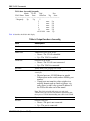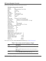
1
Part No. NN47250-100
June 2008
4655 Great America Parkway
Santa Clara, CA 95054
Nortel WLAN Security
Switch 2300 Series
Command Line
Reference
2
Copyright © 2007-2008 Nortel Networks. All rights reserved.
The information in this document is subject to change without notice. The statements, configurations, technical data, and
recommendations in this document are believed to be accurate and reliable, but are presented without express or implied
warranty. Users must take full responsibility for their applications of any products specified in this document. The
information in this document is proprietary to Nortel Networks.
Trademarks and Service Marks
*Nortel, Nortel Networks, the Nortel logo, and the Globemark are trademarks of Nortel Networks.
*Microsoft, MS, MS-DOS, Windows, and Windows NT are registered trademarks of Microsoft Corporation.
*Adobe and Adobe Reader are trademarks of Adobe Systems Incorporated.
All other trademarks and registered trademarks are the property of their respective owners.
Restricted rights legend
Use, duplication, or disclosure by the United States Government is subject to restrictions as set forth in subparagraph
(c)(1)(ii) of the Rights in Technical Data and Computer Software clause at DFARS 252.227-7013.
Notwithstanding any other license agreement that may pertain to, or accompany the delivery of, this computer software,
the rights of the United States Government regarding its use, reproduction, and disclosure are as set forth in the
Commercial Computer Software-Restricted Rights clause at FAR 52.227-19.
Statement of conditions
In the interest of improving internal design, operational function, and/or reliability, Nortel Networks reserves the right to
make changes to the products described in this document without notice.
Nortel Networks does not assume any liability that may occur due to the use or application of the product(s) or circuit
layout(s) described herein.
Portions of the code in this software product may be Copyright © 1988, Regents of the University of California. All
rights reserved. Redistribution and use in source and binary forms of such portions are permitted, provided that the above
copyright notice and this paragraph are duplicated in all such forms and that any documentation, advertising materials,
and other materials related to such distribution and use acknowledge that such portions of the software were developed
by the University of California, Berkeley. The name of the University may not be used to endorse or promote products
derived from such portions of the software without specific prior written permission.
NN47250-100 (Version 02.51)
3
SUCH PORTIONS OF THE SOFTWARE ARE PROVIDED “AS IS” AND WITHOUT ANY EXPRESS OR IMPLIED
WARRANTIES, INCLUDING, WITHOUT LIMITATION, THE IMPLIED WARRANTIES OF
MERCHANTABILITY AND FITNESS FOR A PARTICULAR PURPOSE.
In addition, the program and information contained herein are licensed only pursuant to a license agreement that contains
restrictions on use and disclosure (that may incorporate by reference certain limitations and notices imposed by third
parties).
Nortel Networks software license agreement
This Software License Agreement (“License Agreement”) is between you, the end-user (“Customer”) and Nortel
Corporation and its subsidiaries and affiliates (“Nortel Networks”). PLEASE READ THE FOLLOWING CAREFULLY.
YOU MUST ACCEPT THESE LICENSE TERMS IN ORDER TO DOWNLOAD AND/OR USE THE SOFTWARE.
USE OF THE SOFTWARE CONSTITUTES YOUR ACCEPTANCE OF THIS LICENSE AGREEMENT. If you do not
accept these terms and conditions, return the Software, unused and in the original shipping container, within 30 days of
purchase to obtain a credit for the full purchase price.
“Software” is owned or licensed by Nortel, its parent or one of its subsidiaries or affiliates, and is copyrighted and
licensed, not sold. Software consists of machine-readable instructions, its components, data, audio-visual content (such
as images, text, recordings or pictures) and related licensed materials including all whole or partial copies. Nortel grants
you a license to use the Software only in the country where you acquired the Software. You obtain no rights other than
those granted to you under this License Agreement. You are responsible for the selection of the Software and for the
installation of, use of, and results obtained from the Software.
1.Licensed Use of Software. Nortel Networks grants Customer a nonexclusive license to use a copy of the Software on
only one machine at any one time or to the extent of the activation or authorized usage level, whichever is applicable. To
the extent Software is furnished for use with designated hardware or Customer furnished equipment (“CFE”), Customer
is granted a nonexclusive license to use Software only on such hardware or CFE, as applicable. Software contains trade
secrets and Customer agrees to treat Software as confidential information using the same care and discretion Customer
uses with its own similar information that it does not wish to disclose, publish or disseminate. Customer will ensure that
anyone who uses the Software does so only in compliance with the terms of this Agreement. Customer shall not a) use,
copy, modify, transfer or distribute the Software except as expressly authorized; b) reverse assemble, reverse compile,
reverse engineer or otherwise translate the Software; c) create derivative works or modifications unless expressly
authorized; or d) sublicense, rent or lease the Software. Licensors of intellectual property to Nortel are beneficiaries of
this provision. Upon termination or breach of the license by Customer or in the event designated hardware or CFE is no
longer in use, Customer will promptly return the Software to Nortel or certify its destruction. Nortel may audit by remote
polling or other reasonable means to determine Customer’s Software activation or usage levels. If suppliers of third
party software included in Software require Nortel to include additional or different terms, Customer agrees to abide by
such terms provided by Nortel with respect to such third party software.
2.Warranty. Except as may be otherwise expressly agreed to in writing between Nortel Networks and Customer,
Software is provided “AS IS” without any warranties (conditions) of any kind. NORTEL NETWORKS DISCLAIMS
ALL WARRANTIES (CONDITIONS) FOR THE SOFTWARE, EITHER EXPRESS OR IMPLIED, INCLUDING,
BUT NOT LIMITED TO THE IMPLIED WARRANTIES OF MERCHANTABILITY AND FITNESS FOR A
PARTICULAR PURPOSE AND ANY WARRANTY OF NON-INFRINGEMENT. Nortel Networks is not obligated to
provide support of any kind for the Software. Some jurisdictions do not allow exclusion of implied warranties, and, in
such event, the above exclusions may not apply.
3.Limitation of Remedies. IN NO EVENT SHALL NORTEL OR ITS AGENTS OR SUPPLIERS BE LIABLE FOR
ANY OF THE FOLLOWING: a) DAMAGES BASED ON ANY THIRD PARTY CLAIM; b) LOSS OF, OR DAMAGE
TO, CUSTOMER’S RECORDS, FILES OR DATA; OR c) DIRECT, INDIRECT, SPECIAL, INCIDENTAL,
PUNITIVE, OR CONSEQUENTIAL DAMAGES (INCLUDING LOST PROFITS OR SAVINGS), WHETHER IN
CONTRACT, TORT OR OTHERWISE (INCLUDING NEGLIGENCE) ARISING OUT OF YOUR USE OF THE
SOFTWARE, EVEN IF NORTEL NETWORKS, ITS AGENTS OR SUPPLIERS HAVE BEEN ADVISED OF THEIR
POSSIBILITY. The forgoing limitations of remedies also apply to any developer and/or supplier of the Software. Such
Nortel WLAN—Security Switch 2300 Series Command Line Reference
4
developer and/or supplier is an intended beneficiary of this Section. Some jurisdictions do not allow these limitations or
exclusions and, in such event, they may not apply.
4.General
a)If Customer is the United States Government, the following paragraph shall apply: All Nortel Software available under
this License Agreement is commercial computer software and commercial computer software documentation and, in the
event Software is licensed for or on behalf of the United States Government, the respective rights to the software and
software documentation are governed by Nortel standard commercial license in accordance with U.S. Federal
Regulations at 48 C.F.R. Sections 12.212 (for non-DoD entities) and 48 C.F.R. 227.7202 (for DoD entities).
b)Customer may terminate the license at any time. Nortel may terminate the license if Customer fails to comply with the
terms and conditions of this license. In either event, upon termination, Customer must either return the Software to
Nortel or certify its destruction.
c)Customer is responsible for payment of any taxes, including personal property taxes, resulting from Customer’s use of
the Software. Customer agrees to comply with all applicable laws including all applicable export and import laws and
regulations.
d)Neither party may bring an action, regardless of form, more than two years after the cause of the action arose.
e)The terms and conditions of this License Agreement form the complete and exclusive agreement between Customer
and Nortel.
f)This License Agreement is governed by the laws of the country in which Customer acquires the Software. If the
Software is acquired in the United States, then this License Agreement is governed by the laws of the state of New York.
Legal Information
This section includes the following legal information:
•
“Trademarks and Service Marks” on page 2
•
“Limited Product Warranty” on page 4
•
“Software License Agreement” on page 6
•
“SSH Source Code Statement” on page 8
•
“OpenSSL Project License Statements” on page 9
Limited Product Warranty
The following sections describe the Nortel standard Product Warranty for End Users.
Products
Nortel WLAN—Security Switch 2300 Series
Nortel WLAN — Access Point (2330/2330A/2330B and Series 2332)
Limited Warranty
Nortel standard warranty for hardware is one (1) year. Nortel warrants software materials to be defect free for
90 Days from time of purchase. Nortel requires purchasing the software subscription if a customer would like
to receive new versions of Nortel WLAN—Security Switch 2300 Series and Nortel WLAN — Management
System software. This limited warranty extends only to you the original purchaser of the Product.
NN47250-100 (Version 02.51)
5
Exclusive Remedy
Your sole remedy under the limited warranty described above is, at Nortel’s sole option and expense, the
repair or replacement of the non-conforming Product or refund of the purchase price of the non-conforming
Products. Nortel’s obligation under this limited warranty is subject to compliance with Nortel’s then-current
Return Material Authorization (“RMA”) procedures. All replaced Products will become the property of
Nortel. Exchange Products not returned to Nortel will be invoiced at full Product list prices. Replacement
Products may be new, reconditioned or contain refurbished materials. In connection with any warranty
services hereunder, Nortel may in its sole discretion modify the Product at no cost to you to improve its
reliability or performance.
Warranty Claim Procedures
Should a Product fail to conform to the limited warranty during the applicable warranty period as described
above, Nortel must be notified during the applicable warranty period in order to have any obligation under the
limited warranty.
The End Customer or their designated reseller must obtain a Return Material Authorization number (RMA
number) from Nortel for the non-conforming Product and the non-conforming Product must be returned to
Nortel according to the then-current RMA procedures. The End Customer or their designated reseller is
responsible to ensure that the shipments are insured, with the transportation charges prepaid and that the RMA
number is clearly marked on the outside of the package. Nortel will not accept collect shipments or those
returned without an RMA number clearly visible on the outside of the package.
Exclusions and Restrictions
Nortel shall not be responsible for any software, firmware, information or memory data contained in, stored on
or integrated with any Product returned to Nortel pursuant to any warranty or repair.
Upon return of repaired or replaced Products by Nortel, the warranty with respect to such Products will
continue for the remaining unexpired warranty or sixty (60) days, whichever is longer. Nortel may provide
out-of-warranty repair for the Products at its then-prevailing repair rates.
The limited warranty for the Product does not apply if, in the judgment of Nortel, the Product fails due to
damage from shipment, handling, storage, accident, abuse or misuse, or it has been used or maintained in a
manner not conforming to Product manual instructions, has been modified in any way, or has had any Serial
Number removed or defaced. Repair by anyone other than Nortel or an approved agent will void this warranty.
EXCEPT FOR ANY EXPRESS LIMITED WARRANTIES FROM Nortel SET FORTH ABOVE, THE
PRODUCT IS PROVIDED “AS IS”, AND NORTEL AND ITS SUPPLIERS MAKE NO WARRANTY,
EXPRESS, IMPLIED, STATUTORY OR OTHERWISE, WITH RESPECT TO PRODUCT OR ANY PART
THEREOF, INCLUDING WITHOUT LIMITATION ANY IMPLIED WARRANTY OF TITLE,
MERCHANTABILITY, FITNESS FOR A PARTICULAR PURPOSE, NON-INFRINGEMENT, OR THOSE
ARISING FROM COURSE OF PERFORMANCE, DEALING, USAGE OR TRADE. NORTEL’S
SUPPLIERS MAKE NO DIRECT WARRANTY OF ANY KIND TO END CUSTOMER FOR THE
LICENSED MATERIALS. NEITHER Nortel NOR ANY OF ITS SUPPLIERS WARRANT THAT THE
LICENSED MATERIALS OR ANY PART THEREOF WILL MEET END CUSTOMER'S
REQUIREMENTS OR BE UNINTERRUPTED, OR ERROR-FREE, OR THAT ANY ERRORS IN THE
PRODUCT WILL BE CORRECTED. SOME STATES/JURISDICTIONS DO NOT ALLOW THE
EXCLUSION OF IMPLIED WARRANTIES SO THE ABOVE EXCLUSIONS MAY NOT APPLY TO
END CUSTOMER. THIS LIMITED WARRANTY GIVES END CUSTOMER SPECIFIC LEGAL RIGHTS.
Nortel WLAN—Security Switch 2300 Series Command Line Reference
6
END CUSTOMER MAY ALSO HAVE OTHER RIGHTS, WHICH VARY FROM STATE/JURISDICTION
TO STATE/JURISDICTION.
TO THE MAXIMUM EXTENT PERMITTED BY APPLICABLE LAW, IN NO EVENT SHALL NORTEL
OR ITS SUPPLIERS BE LIABLE FOR THE COST OF PROCUREMENT OF SUBSTITUTE GOODS OR
SERVICES, LOSS OF PROFITS, OR FOR ANY SPECIAL, CONSEQUENTIAL, INCIDENTAL,
PUNITIVE OR INDIRECT DAMAGES (OR DIRECT DAMAGES IN THE CASE OF NORTEL’S
SUPPLIERS) ON ANY THEORY OF LIABILITY, WHETHER IN CONTRACT, TORT (INCLUDING
WITHOUT LIMITATION NEGLIGENCE), STRICT LIABILITY OR OTHERWISE ARISING OUT OF OR
RELATED TO THE PRODUCT OR ANY USE OR INABILITY TO USE THE PRODUCT. Nortel ’S
TOTAL LIABILITY ARISING OUT OF OR RELATED TO THE PRODUCT, OR USE OR INABILITY TO
USE THE PRODUCT, WHETHER IN CONTRACT, TORT (INCLUDING WITHOUT LIMITATION
NEGLIGENCE), STRICT LIABILITY OR OTHERWISE, SHALL NOT EXCEED THE PRICE PAID FOR
THE PRODUCT. THE LIMITATIONS SET FORTH IN THIS SECTION SHALL APPLY EVEN IF Nortel
AND/OR ITS SUPPLIERS ARE ADVISED OF THE POSSIBILITY OF SUCH DAMAGE, AND
NOTWITHSTANDING THE FAILURE OF ESSENTIAL PURPOSE OF ANY LIMITED REMEDY. Nortel
NEITHER ASSUMES NOR AUTHORIZES ANY OTHER PERSON TO ASSUME FOR IT ANY OTHER
LIABILITY IN CONNECTION WITH THE SALE, INSTALLATION, MAINTENANCE OR USE OF ITS
PRODUCTS.
Software License Agreement
PLEASE READ THIS SOFTWARE LICENSE AGREEMENT (“AGREEMENT”) CAREFULLY BEFORE USING THE SOFTWARE AND
ASSOCIATED DOCUMENTATION THAT IS PROVIDED WITH THIS AGREEMENT (“SOFTWARE,” “DOCUMENTATION,” AND
COLLECTIVELY, “LICENSED MATERIALS”).
BY USING ANY LICENSED MATERIALS, YOU ACKNOWLEDGE THAT YOU HAVE READ AND UNDERSTOOD ALL THE TERMS AND
CONDITIONS OF THIS AGREEMENT AND YOU WILL BE CONSENTING TO BE BOUND BY THEM. IF YOU DO NOT ACCEPT
THESE TERMS AND CONDITIONS, DO NOT USE THE LICENSED MATERIALS AND RETURN THE LICENSED MATERIALS AND
ANY EQUIPMENT PROVIDED BY Nortel IN CONNECTION THEREWITH (“EQUIPMENT”) UNUSED IN THE ORIGINAL SHIPPING
CONTAINER TO THE PLACE OF PURCHASE FOR A FULL REFUND.
Software may be provided by Nortel on a standalone basis (“Standalone Software”) or it may be provided embedded in
Equipment (“Embedded Software”).
1.
License.
(a)
Subject to the terms and conditions of this Agreement, Nortel (“Nortel”), grants to you (“Licensee”) a limited,
non-exclusive, non-transferable license, without the right to sublicense: (i) to install and use the Standalone Software, in
object code format only, on computer hardware for which all corresponding license fees have been paid; (ii) use one (1)
copy of the Embedded Software, in object code format only, solely as embedded in Equipment, each solely in accordance
with the Documentation for Licensee’s internal business purposes.
(b)
The license set forth above does not include any rights to and Licensee shall not (i) reproduce (except as set
forth in Section 1(c)), modify, translate or create any derivative work of all or any portion of the Licensed Materials or
Equipment, (ii) sell, rent, lease, loan, provide, distribute or otherwise transfer all or any portion of the Licensed Materials
(except as set forth in Section 1(f)), (iii) reverse engineer, reverse assemble or otherwise attempt to gain access to the
source code of all or any portion of the Licensed Materials or Equipment, (iv) use the Licensed Materials for third-party
training, commercial time-sharing or service bureau use, (v) remove, alter, cover or obfuscate any copyright notices,
trademark notices or other proprietary rights notices placed or embedded on or in the Licensed Materials or Equipment, (vi)
use any component of the Software or Equipment other than solely in conjunction with operation of the Software and as
applicable, Equipment, (vii) unbundle any component of the Software or Equipment, (viii) use any component of the
Software for the development of or in conjunction with any software application intended for resale that employs any such
component, (ix) use the Licensed Materials or Equipment in life support systems, human implantation, nuclear facilities or
systems or any other application where failure could lead to a loss of life or catastrophic property damage, or (x) cause or
permit any third party to do any of the foregoing.
If Licensee is a European Union resident, Licensee acknowledges that information necessary to achieve interoperability of
the Software with other programs is available upon request.
(c)
Licensee may make a single copy of the Standalone Software and Documentation solely for its back-up purposes;
provided that any such copy is the exclusive property of Nortel and its suppliers and includes all copyright and other
intellectual property right notices that appear on the original.
NN47250-100 (Version 02.51)
7
(d)
Nortel may provide updates, corrections, enhancements, modifications or bug fixes for the Licensed Materials
(“Updates”) to Licensee. Any such Update shall be deemed part of the Licensed Materials and subject to the license and all
other terms and conditions hereunder.
(e)
Nortel shall have the right to inspect and audit Licensee’s use, deployment, and exploitation of the Licensed
Materials for compliance with the terms and conditions of this Agreement.
(f)
Licensee shall have the right to transfer the Embedded Software as embedded in Equipment in connection with
a transfer of all of Licensee’s right, title and interest in such Equipment to a third party; provided, that, Licensee transfers
the Embedded Software and any copies thereof subject to the terms and conditions of this Agreement and such third party
agrees in writing to be bound by all the terms and conditions of this Agreement.
(g)
Notwithstanding anything to the contrary herein, certain portions of the Software are licensed under and
Licensee's use of such portions are only subject to the GNU General Public License version 2. If Licensee or any third party
sends a request in writing to Nortel at 110 Nortech Parkway, San Jose CA 95134, ATTN: Contracts Administration, Nortel
will provide a complete machine-readable copy of the source code of such portions for a nominal cost to cover Nortel's cost
in physically providing such code.
2.
Ownership. Nortel or its suppliers own and shall retain all right, title and interest (including without limitation all
intellectual property rights), in and to the Licensed Materials and any Update, whether or not made by Nortel. Licensee
acknowledges that the licenses granted under this Agreement do not provide Licensee with title to or ownership of the
Licensed Materials, but only a right of limited use under the terms and conditions of this Agreement. Except as expressly
set forth in Section 1, Nortel reserves all rights and grants Licensee no licenses of any kind hereunder. All information or
feedback provided by Licensee to Nortel with respect to the Software or Equipment shall be Nortel’s property and deemed
confidential information of Nortel.
3.
Confidentiality. Licensee agrees that the Licensed Materials contain confidential information, including trade secrets,
know-how, and information pertaining to the technical structure or performance of the Software, that is the exclusive
property of Nortel as between Licensee and Nortel. In addition, Nortel’s confidential information includes any confidential or
trade secret information related to the Licensed Materials. During the period this Agreement is in effect and at all times
thereafter, Licensee shall maintain Nortel’s confidential information in confidence and use the same degree of care, but in
no event less than reasonable care, to avoid disclosure of Nortel’s confidential information as it uses with respect to its own
confidential and proprietary information of similar type and importance. Licensee agrees to only disclose Nortel’s confidential
information to its directors, officers and employees who have a bona fide need to know solely to exercise Licensee’s rights
under this Agreement and to only use Nortel’s confidential information incidentally in the customary operation of the
Software and Equipment. Licensee shall not sell, license, sublicense, publish, display, distribute, disclose or otherwise make
available Nortel’s confidential information to any third party nor use such information except as authorized by this
Agreement. Licensee agrees to immediately notify Nortel of the unauthorized disclosure or use of the Licensed Materials and
to assist Nortel in remedying such unauthorized use or disclosure. It is further understood and agreed that any breach of
this Section 3 or Section 1(b) is a material breach of this Agreement and any such breach would cause irreparable harm to
Nortel and its suppliers, entitling Nortel or its suppliers to injunctive relief in addition to all other remedies available at law.
4.
Limited Warranty & Disclaimer. Any limited warranty for the Licensed Materials and Nortel’s sole and exclusivity
liability thereunder is as set forth in Nortel’s standard warranty documentation. In addition, any limited warranty for the
Software does not apply to any component of the Software but only to the Software as a whole. EXCEPT FOR ANY EXPRESS
LIMITED WARRANTIES FROM Nortel IN SUCH DOCUMENTATION, THE LICENSED MATERIALS ARE PROVIDED “AS IS”, AND
Nortel AND ITS SUPPLIERS MAKE NO WARRANTY, EXPRESS, IMPLIED, STATUTORY OR OTHERWISE, WITH RESPECT TO
LICENSED MATERIALS OR ANY PART THEREOF, INCLUDING WITHOUT LIMITATION ANY IMPLIED WARRANTY OF TITLE,
MERCHANTABILITY, FITNESS FOR A PARTICULAR PURPOSE, NONINFRINGEMENT, OR THOSE ARISING FROM COURSE OF
PERFORMANCE, DEALING, USAGE OR TRADE. Nortel ’S SUPPLIERS MAKE NO DIRECT WARRANTY OF ANY KIND TO LICENSEE FOR THE LICENSED MATERIALS. NEITHER Nortel NOR ANY OF ITS SUPPLIERS WARRANT THAT THE LICENSED MATERIALS OR ANY PART THEREOF WILL MEET LICENSEE’S REQUIREMENTS OR BE UNINTERRUPTED, OR ERROR-FREE, OR THAT
ANY ERRORS IN THE LICENSED MATERIALS WILL BE CORRECTED. SOME STATES/JURISDICTIONS DO NOT ALLOW THE
EXCLUSION OF IMPLIED WARRANTIES SO THE ABOVE EXCLUSIONS MAY NOT APPLY TO LICENSEE. THIS LIMITED WARRANTY GIVES LICENSEE SPECIFIC LEGAL RIGHTS. LICENSEE MAY ALSO HAVE OTHER RIGHTS, WHICH VARY FROM
STATE/JURISDICTION TO STATE/JURISDICTION.
5.
Term and Termination. This Agreement is effective until terminated. License may terminate this Agreement at any
time by destroying all copies of the Software. This Agreement and all licenses granted hereunder will terminate immediately
without notice from Nortel if Licensee fails to comply with any provision of this Agreement. Upon any termination, Licensee
must destroy all copies of the Licensed Materials. Sections 1(b), 2, 3, 4(b), 5, 6, 7, 8, 9 and 10 shall survive any termination
of this Agreement.
6.
Export. The Software is specifically subject to U.S. Export Administration Regulations. Licensee agrees to strictly
comply with all export, re-export and import restrictions and regulations of the Department of Commerce or other agency
or authority of the United States or other applicable countries, and not to transfer, or authorize the transfer of, directly or
indirectly, the Software or any direct product thereof to a prohibited country or otherwise in violation of any such restrictions
or regulations. Licensee’s failure to comply with this Section is a material breach of this Agreement. Licensee acknowledges
that Licensee is not a national of Cuba, Iran, Iraq, Libya, North Korea, Sudan or Syria or a party listed in the U.S. Table of
Denial Orders or U.S. Treasury Department List of Specially Designated Nationals.
7.
Government Restricted Rights. As defined in FAR section 2.101, DFAR section 252.227-7014(a)(1) and DFAR section
252.227-7014(a)(5) or otherwise, the Software provided in connection with this Agreement are “commercial items,”
“commercial computer software” and/or “commercial computer software documentation.” Consistent with DFAR section
227.7202, FAR section 12.212 and other sections, any use, modification, reproduction, release, performance, display,
disclosure or distribution thereof by or for the U.S. Government shall be governed solely by the terms of this Agreement
and shall be prohibited except to the extent expressly permitted by the terms of this Agreement. Any technical data provided
Nortel WLAN—Security Switch 2300 Series Command Line Reference
8
that is not covered by the above provisions shall be deemed “technical data-commercial items” pursuant to DFAR section
227.7015(a). Any use, modification, reproduction, release, performance, display or disclosure of such technical data shall
be governed by the terms of DFAR section 227.7015(b).
8.
Limitation of Liability. TO THE MAXIMUM EXTENT PERMITTED BY APPLICABLE LAW, IN NO EVENT SHALL Nortel OR
ITS SUPPLIERS BE LIABLE FOR THE COST OF PROCUREMENT OF SUBSTITUTE GOODS OR SERVICES, LOSS OF PROFITS,
OR FOR ANY SPECIAL, CONSEQUENTIAL, INCIDENTAL, PUNITIVE OR INDIRECT DAMAGES (OR DIRECT DAMAGES IN THE
CASE OF Nortel ’S SUPPLIERS) ON ANY THEORY OF LIABILITY, WHETHER IN CONTRACT, TORT (INCLUDING WITHOUT
LIMITATION NEGLIGENCE), STRICT LIABILITY OR OTHERWISE ARISING OUT OF OR UNDER THIS AGREEMENT OR ANY USE
OR INABILITY TO USE THE LICENSED MATERIALS OR EQUIPMENT, OR FOR BREACH OF THIS AGREEMENT. Nortel ’S TOTAL
LIABILITY ARISING OUT OF OR UNDER THIS AGREEMENT, OR USE OR INABILITY TO USE THE LICENSED MATERIALS OR
EQUIPMENT, OR FOR BREACH OF THIS AGREEMENT, WHETHER IN CONTRACT, TORT (INCLUDING WITHOUT LIMITATION
NEGLIGENCE), STRICT LIABILITY OR OTHERWISE, SHALL NOT EXCEED THE PRICE PAID FOR THE SOFTWARE (FOR THE
STANDALONE SOFTWARE) AND THE PRICE PAID FOR THE EQUIPMENT (FOR THE EMBEDDED SOFTWARE AND EQUIPMENT).
THE LIMITATIONS SET FORTH IN THIS SECTION SHALL APPLY EVEN IF Nortel AND/OR ITS SUPPLIERS ARE ADVISED OF
THE POSSIBILITY OF SUCH DAMAGE, AND NOTWITHSTANDING THE FAILURE OF ESSENTIAL PURPOSE OF ANY LIMITED
REMEDY.
9.
Third Party Beneficiaries. Nortel’s suppliers are intended third party beneficiaries of this Agreement. The terms and
conditions herein are made expressly for the benefit of and are enforceable by Nortel’s suppliers; provided, however, that
Nortel’s suppliers are not in any contractual relationship with Licensee. Nortel’s suppliers include without limitation: (a) Hifn,
Inc., a Delaware corporation with principal offices at 750 University Avenue, Los Gatos, California; and (b) Wind River
Systems, Inc. and its suppliers.
10.
General. This Agreement is governed and interpreted in accordance with the laws of the State of California, U.S.A.
without reference to conflicts of laws principles and excluding the United Nations Convention on Contracts for the Sale of
Goods. The parties consent to the exclusive jurisdiction of, and venue in, Santa Clara County, California, U.S.A. Licensee
shall not transfer, assign or delegate this Agreement or any rights or obligations hereunder, whether voluntarily, by
operation of law or otherwise, without the prior written consent of Nortel (except as expressly set forth in Section 1(f)).
Subject to the foregoing, the terms and conditions of this Agreement shall be binding upon and inure to the benefit of the
parties to it and their respective heirs, successors, assigns and legal representatives. This Agreement constitutes the entire
agreement between Nortel and Licensee with respect to the subject matter hereof, and merges all prior negotiations and
drafts of the parties with regard thereto. No modification of or amendment to this Agreement, nor any waiver of any rights
under this Agreement, by Nortel shall be effective unless in writing. If any of the provisions of this Agreement is held by a
court of competent jurisdiction to be invalid or unenforceable under any applicable statute or rule of law, such provision
shall, to that extent, be deemed omitted.
SSH Source Code Statement
C 1995 - 2004 SAFENET, Inc. This software is protected by international copyright laws. All rights reserved. SafeNet is a
registered trademark of SAFENET, Inc., in the United States and in certain other jurisdictions. SAFENET and the SAFENET
logo are trademarks of SAFENET, Inc., and may be registered in certain jurisdictions. All other names and marks are
property of their respective owners.
Copyright (c) 1983, 1990, 1992, 1993, 1995 The Regents of the University of California. All rights reserved.
THIS SOFTWARE IS PROVIDED BY THE REGENTS AND CONTRIBUTORS ``AS IS'' AND ANY EXPRESS OR IMPLIED
WARRANTIES, INCLUDING, BUT NOT LIMITED TO, THE IMPLIED WARRANTIES OF MERCHANTABILITY AND FITNESS FOR A
PARTICULAR PURPOSE ARE DISCLAIMED. IN NO EVENT SHALL THE REGENTS OR CONTRIBUTORS BE LIABLE FOR ANY
DIRECT, INDIRECT, INCIDENTAL, SPECIAL, EXEMPLARY, OR CONSEQUENTIAL DAMAGES (INCLUDING, BUT NOT LIMITED
TO, PROCUREMENT OF SUBSTITUTE GOODS OR SERVICES; LOSS OF USE, DATA, OR PROFITS; OR BUSINESS
INTERRUPTION) HOWEVER CAUSED AND ON ANY THEORY OF LIABILITY, WHETHER IN CONTRACT, STRICT LIABILITY, OR
TORT (INCLUDING NEGLIGENCE OR OTHERWISE) ARISING IN ANY WAY OUT OF THE USE OF THIS SOFTWARE, EVEN IF
ADVISED OF THE POSSIBILITY OF SUCH DAMAGE.
Components of the software are provided under a standard 2-term BSD licence with the following names as copyright
holders:
o Markus Friedl
o Theo de Raadt
o Niels Provos
o Dug Song
o Aaron Campbell
o Damien Miller
o Kevin Steves
o Daniel Kouril
o Per Allansson
NN47250-100 (Version 02.51)
9
THIS SOFTWARE IS PROVIDED BY THE AUTHOR ``AS IS'' AND ANY EXPRESS OR IMPLIED WARRANTIES, INCLUDING, BUT
NOT LIMITED TO, THE IMPLIED WARRANTIES OF MERCHANTABILITY AND FITNESS FOR A PARTICULAR PURPOSE ARE
DISCLAIMED. IN NO EVENT SHALL THE AUTHOR BE LIABLE FOR ANY DIRECT, INDIRECT, INCIDENTAL, SPECIAL,
EXEMPLARY, OR CONSEQUENTIAL DAMAGES (INCLUDING, BUT NOT LIMITED TO, PROCUREMENT OF SUBSTITUTE GOODS
OR SERVICES; LOSS OF USE, DATA, OR PROFITS; OR BUSINESS INTERRUPTION) HOWEVER CAUSED AND ON ANY THEORY
OF LIABILITY, WHETHER IN CONTRACT, STRICT LIABILITY, OR TORT (INCLUDING NEGLIGENCE OR OTHERWISE) ARISING
IN ANY WAY OUT OF THE USE OF THIS SOFTWARE, EVEN IF ADVISED OF THE POSSIBILITY OF SUCH DAMAGE.
OpenSSL Project License Statements
Copyright (c) 1998-2002 The OpenSSL Project. All rights reserved.
THIS SOFTWARE IS PROVIDED BY THE OpenSSL PROJECT ``AS IS'' AND ANY EXPRESSED OR IMPLIED WARRANTIES,
INCLUDING, BUT NOT LIMITED TO, THE IMPLIED WARRANTIES OF MERCHANTABILITY AND FITNESS FOR A PARTICULAR
PURPOSE ARE DISCLAIMED. IN NO EVENT SHALL THE OpenSSL PROJECT OR ITS CONTRIBUTORS BE LIABLE FOR ANY
DIRECT, INDIRECT, INCIDENTAL, SPECIAL, EXEMPLARY, OR CONSEQUENTIAL DAMAGES (INCLUDING, BUT NOT LIMITED
TO, PROCUREMENT OF SUBSTITUTE GOODS OR SERVICES; LOSS OF USE, DATA, OR PROFITS; OR BUSINESS
INTERRUPTION) HOWEVER CAUSED AND ON ANY THEORY OF LIABILITY, WHETHER IN CONTRACT, STRICT LIABILITY, OR
TORT (INCLUDING NEGLIGENCE OR OTHERWISE) ARISING IN ANY WAY OUT OF THE USE OF THIS SOFTWARE, EVEN IF
ADVISED OF THE POSSIBILITY OF SUCH DAMAGE.
Copyright (C) 1995-1998 Eric Young ([email protected]). All rights reserved.
THIS SOFTWARE IS PROVIDED BY ERIC YOUNG ``AS IS'' AND ANY EXPRESS OR IMPLIED WARRANTIES, INCLUDING, BUT
NOT LIMITED TO, THE IMPLIED WARRANTIES OF MERCHANTABILITY AND FITNESS FOR A PARTICULAR PURPOSE ARE
DISCLAIMED. IN NO EVENT SHALL THE AUTHOR OR CONTRIBUTORS BE LIABLE FOR ANY DIRECT, INDIRECT, INCIDENTAL,
SPECIAL, EXEMPLARY, OR CONSEQUENTIAL DAMAGES (INCLUDING, BUT NOT LIMITED TO, PROCUREMENT OF SUBSTITUTE
GOODS OR SERVICES; LOSS OF USE, DATA, OR PROFITS; OR BUSINESS INTERRUPTION) HOWEVER CAUSED AND ON ANY
THEORY OF LIABILITY, WHETHER IN CONTRACT, STRICT LIABILITY, OR TORT (INCLUDING NEGLIGENCE OR OTHERWISE)
ARISING IN ANY WAY OUT OF THE USE OF THIS SOFTWARE, EVEN IF ADVISED OF THE POSSIBILITY OF SUCH DAMAGE.
Nortel WLAN—Security Switch 2300 Series Command Line Reference
10
NN47250-100 (Version 02.51)
11
How to get help . . . . . . . . . . . . . . . . . . . . . . . . . . . . . . . . . . . . . . . . . . . . . 3
Introducing the Nortel WLAN 2300 System . . . . . . . . . . . . . . . . . . . . . . . 5
Nortel WLAN 2300 System . . . . . . . . . . . . . . . . . . . . . . . . . . . . . . . . . . . . . . . . . . . 5
Documentation . . . . . . . . . . . . . . . . . . . . . . . . . . . . . . . . . . . . . . . . . . . . . . . . . . . . 6
Safety and Advisory Notices . . . . . . . . . . . . . . . . . . . . . . . . . . . . . . . . . . . . . . . 7
Text and Syntax Conventions . . . . . . . . . . . . . . . . . . . . . . . . . . . . . . . . . . . . . . 8
Using the Command-Line Interface . . . . . . . . . . . . . . . . . . . . . . . . . . . . . 9
CLI Conventions . . . . . . . . . . . . . . . . . . . . . . . . . . . . . . . . . . . . . . . . . . . . . . . . . . . 9
Command Prompts . . . . . . . . . . . . . . . . . . . . . . . . . . . . . . . . . . . . . . . . . . . . . 10
Syntax Notation . . . . . . . . . . . . . . . . . . . . . . . . . . . . . . . . . . . . . . . . . . . . . . . . 11
Text Entry Conventions and Allowed Characters . . . . . . . . . . . . . . . . . . . . . . 11
MAC Address Notation . . . . . . . . . . . . . . . . . . . . . . . . . . . . . . . . . . . . . . . . . . 12
IP Address and Mask Notation . . . . . . . . . . . . . . . . . . . . . . . . . . . . . . . . . . . . 12
Subnet Masks . . . . . . . . . . . . . . . . . . . . . . . . . . . . . . . . . . . . . . . . . . . . . . 12
Wildcard Masks . . . . . . . . . . . . . . . . . . . . . . . . . . . . . . . . . . . . . . . . . . . . 12
User Wildcards, MAC Address Wildcards, and VLAN Wildcards . . . . . . . . . . 12
User Wildcards . . . . . . . . . . . . . . . . . . . . . . . . . . . . . . . . . . . . . . . . . . . . . 12
MAC Address Wildcards . . . . . . . . . . . . . . . . . . . . . . . . . . . . . . . . . . . . . . 13
VLAN Wildcards . . . . . . . . . . . . . . . . . . . . . . . . . . . . . . . . . . . . . . . . . . . . 13
Matching Order for Wildcards . . . . . . . . . . . . . . . . . . . . . . . . . . . . . . . . . . 14
Port Lists . . . . . . . . . . . . . . . . . . . . . . . . . . . . . . . . . . . . . . . . . . . . . . . . . . . . . 14
Virtual LAN Identification . . . . . . . . . . . . . . . . . . . . . . . . . . . . . . . . . . . . . . . . . 14
Command-Line Editing . . . . . . . . . . . . . . . . . . . . . . . . . . . . . . . . . . . . . . . . . . . . . 15
Using CLI Help . . . . . . . . . . . . . . . . . . . . . . . . . . . . . . . . . . . . . . . . . . . . . . . . . . . 16
Understanding Command Descriptions . . . . . . . . . . . . . . . . . . . . . . . . . . . . . . . . . 17
Access Commands . . . . . . . . . . . . . . . . . . . . . . . . . . . . . . . . . . . . . . . . . 19
Port Commands . . . . . . . . . . . . . . . . . . . . . . . . . . . . . . . . . . . . . . . . . . . . 23
System Services Commands . . . . . . . . . . . . . . . . . . . . . . . . . . . . . . . . . 53
VLAN Commands. . . . . . . . . . . . . . . . . . . . . . . . . . . . . . . . . . . . . . . . . . . 73
Quality of Service Commands . . . . . . . . . . . . . . . . . . . . . . . . . . . . . . . . 93
Nortel WLAN—Management Software 2300 Series Reference Guide
12
IP Services Commands . . . . . . . . . . . . . . . . . . . . . . . . . . . . . . . . . . . . . . 97
AAA Commands. . . . . . . . . . . . . . . . . . . . . . . . . . . . . . . . . . . . . . . . . . . 165
Mobility Domain Commands. . . . . . . . . . . . . . . . . . . . . . . . . . . . . . . . . 217
Network Domain Commands . . . . . . . . . . . . . . . . . . . . . . . . . . . . . . . . 225
AP Commands . . . . . . . . . . . . . . . . . . . . . . . . . . . . . . . . . . . . . . . . . . . . 233
STP Commands . . . . . . . . . . . . . . . . . . . . . . . . . . . . . . . . . . . . . . . . . . . 389
IGMP Snooping Commands . . . . . . . . . . . . . . . . . . . . . . . . . . . . . . . . . 415
Session Management Commands . . . . . . . . . . . . . . . . . . . . . . . . . . . . 435
Security ACL Commands . . . . . . . . . . . . . . . . . . . . . . . . . . . . . . . . . . . 449
Cryptography Commands . . . . . . . . . . . . . . . . . . . . . . . . . . . . . . . . . . . 469
RADIUS and Server Groups Commands . . . . . . . . . . . . . . . . . . . . . . . 483
802.1X Management Commands . . . . . . . . . . . . . . . . . . . . . . . . . . . . . 495
RF Detection Commands . . . . . . . . . . . . . . . . . . . . . . . . . . . . . . . . . . . 511
File Management Commands . . . . . . . . . . . . . . . . . . . . . . . . . . . . . . . . 535
Trace Commands . . . . . . . . . . . . . . . . . . . . . . . . . . . . . . . . . . . . . . . . . . 559
Snoop Commands . . . . . . . . . . . . . . . . . . . . . . . . . . . . . . . . . . . . . . . . . 565
System Log Commands . . . . . . . . . . . . . . . . . . . . . . . . . . . . . . . . . . . . 575
Boot Prompt Commands. . . . . . . . . . . . . . . . . . . . . . . . . . . . . . . . . . . . 585
Command Index . . . . . . . . . . . . . . . . . . . . . . . . . . . . . . . . . . . . . . . . . . . 601
NN47250-102 (Version 02.51)
13
How to get help
This section explains how to get help for Nortel products and services.
Getting help from the Nortel web site
The best way to get technical support for Nortel products is from the Nortel Technical Support Web site:
http://www.nortel.com/support
This site provides quick access to software, documentation, bulletins, and tools to address issues with Nortel products.
More specifically, the site enables you to:
•
download software, documentation, and product bulletins
•
search the Technical Support Web site and the Nortel Knowledge Base for answers to technical issues
•
sign up for automatic notification of new software and documentation for Nortel equipment
•
open and manage technical support cases
Getting help over the phone from a Nortel solutions center
If you do not find the information you require on the Nortel Technical Support Web site, and have a Nortel support
contract, you can also get help over the phone from a Nortel Solutions Center.
In North America, call 1-800-4NORTEL (1-800-466-7835).
Outside North America, go to the following Web site to obtain the phone number for your region:
http://www.nortel.com/callus
Getting help from a specialist by using an express routing code
To access some Nortel Technical Solutions Centers, you can use an Express Routing Code (ERC) to quickly route your
call to a specialist in your Nortel product or service. To locate the ERC for your product or service, go to:
http://www.nortel.com/erc
Getting help through a Nortel distributor or reseller
If you purchased a service contract for your Nortel product from a distributor or authorized reseller, contact the technical
support staff for that distributor or reseller.
Nortel WLAN—Security Switch 2300 Series Command Line Reference
14 How to get help
NN47250-100 (Version 02.51)
15
Introducing the Nortel WLAN 2300
System
Nortel WLAN 2300 System . . . . . . . . . . . . . . . . . . . . . . . . . . . . . . . . . . . . . . . 5
Documentation . . . . . . . . . . . . . . . . . . . . . . . . . . . . . . . . . . . . . . . . . . . . . . . . . 6
This command reference explains WLAN Security Switch 2300 Series (WSS Software) command line interface (CLI)
commands that you enter on a WLAN—Security Switch to configure and manage the Nortel WLAN 2300 System
wireless LAN (WLAN).
Read this reference if you are a network administrator responsible for managing WLAN—Security Switch (WSS) and
Access Points (APs) in a network.
Nortel WLAN 2300 System
The Nortel WLAN 2300 System is an enterprise-class WLAN solution that seamlessly integrates with an existing wired
enterprise network. The Nortel system provides secure connectivity to both wireless and wired users in large environments such as office buildings, hospitals, and university campuses and in small environments such as branch offices.
The Nortel WLAN 2300 System fulfills the three fundamental requirements of an enterprise WLAN: It eliminates the
distinction between wired and wireless networks, allows users to work safely from anywhere (secure mobility), and
provides a comprehensive suite of intuitive tools for planning and managing the network before and after deployment,
greatly easing the operational burden on IT resources.
The Nortel WLAN 2300 System consists of the following components:
•
WLAN Management Software tool suite—A full-featured graphical user interface (GUI) application used to
plan, configure, deploy, and manage a WLAN and its users
•
One or more WLAN—Security Switch (WSS) —Distributed, intelligent machines for managing user
connectivity, connecting and powering Access Points (APs), and connecting the WLAN to the wired network
backbone
•
Multiple Access Points (APs) —Wireless APs that transmit and receive radio frequency (RF) signals to and from
wireless users and connect them to a WSS
•
WLAN Security Switch 2300 Series (WSS Software)—The operating system that runs all WSSs and APs in a
WLAN, and is accessible through a command-line interface (CLI), the Web View interface, or the WLAN
Management Software GUI
Nortel WLAN—Security Switch 2300 Series Command Line Reference
16 Introducing the Nortel WLAN 2300 System
Documentation
Consult the following documents to plan, install, configure, and manage a Nortel WLAN 2300 System.
Planning, Configuration, and Deployment
•
Nortel WLAN Management Software 2300 Series User Guide. Instructions for planning, configuring, deploying,
and managing the entire WLAN with the WLAN Management Software tool suite. Read this guide to learn how to
plan wireless services, how to configure and deploy Nortel equipment to provide those services, and how to
optimize and manage your WLAN.
•
Nortel WLAN Management Software 2300 Series Reference Guide. Detailed instructions and information for all
WLAN Management Software planning, configuration, and management features.
Installation
•
Nortel WLAN—Security Switch 2300 Series Installation and Basic Configuration Guide. Instructions and
specifications for installing a WSS
•
Nortel WLAN—Security Switch 2300 Series Quick Start Guide. Instructions for performing basic setup of secure
(802.1X) and guest (Web-based AAA) access, and for configuring a Mobility Domain for roaming
•
Nortel WLAN—Access Point 2330/2330A/2330B Installation Guide. Instructions and specifications for installing an
AP and connecting it to a WSS
•
Nortel WLAN—Series 2332 Access Point Installation Guide. Instructions and specifications for installing a Series
2332 AP and connecting it to a WSS
Configuration and Management
•
Nortel WLAN Management Software 2300 Series Reference Guide (this document). Instructions for planning,
configuring, deploying, and managing the entire WLAN with the WLAN Management Software tool suite
•
Nortel WLAN Security Switch 2300 Series Configuration Guide. Instructions for configuring and managing the
system through the WSS Software CLI
•
Nortel WLAN Security Switch 2300 Series Command Line Reference. Functional and alphabetic reference to all
WSS Software commands supported on WSSs and APs
NN47250-100 (Version 02.51)
Introducing the Nortel WLAN 2300 System 17
Safety and Advisory Notices
The following kinds of safety and advisory notices appear in this manual.
Caution! This situation or condition can lead to data loss or damage to the product or
other property.
Note. This information is of special interest.
Nortel WLAN—Security Switch 2300 Series Command Line Reference
18 Introducing the Nortel WLAN 2300 System
Text and Syntax Conventions
Nortel manuals use the following text and syntax conventions:
Convention
Use
Monospace text
Sets off command syntax or sample commands and system
responses.
Bold text
Highlights commands that you enter or items you select.
Italic text
Designates command variables that you replace with
appropriate values, or highlights publication titles or words
requiring special emphasis.
Menu Name > Command
Indicates a menu item that you select. For example, File > New
indicates that you select New from the File menu.
[ ] (square brackets)
Enclose optional parameters in command syntax.
{ } (curly brackets)
Enclose mandatory parameters in command syntax.
| (vertical bar)
Separates mutually exclusive options in command syntax.
NN47250-100 (Version 02.51)
19
Using the Command-Line Interface
CLI Conventions . . . . . . . . . . . . . . . . . . . . . . . . . . . . . . . . . . . . . . . . . . . . . . . . 9
Command-Line Editing . . . . . . . . . . . . . . . . . . . . . . . . . . . . . . . . . . . . . . . . . . 15
Using CLI Help . . . . . . . . . . . . . . . . . . . . . . . . . . . . . . . . . . . . . . . . . . . . . . . . 16
Understanding Command Descriptions . . . . . . . . . . . . . . . . . . . . . . . . . . . . . 17
WLAN Security Switch 2300 Series (WSS Software) operates a Nortel WLAN 2300 System wireless LAN (WLAN)
consisting of WLAN Management Software, WLAN—Security Switch (WSS), and Access Points (APs). WSS Software
has a command-line interface (CLI) on the WSS that you can use to configure and manage the switch and its attached
APs.
You configure the WSS and APs primarily with set, clear, and show commands. Use set commands to change parameters. Use clear commands to reset parameters to their defaults. In many cases, you can overwrite a parameter with
another set command. Use show commands to display the current configuration and monitor the status of network
operations.
The WSS supports two connection modes:
•
Administrative access mode, which enables the network administrator to connect to the WSS and configure the
network
•
Network access mode, which enables network users to connect through the WSS to access the network
CLI Conventions
Be aware of the following WSS Software CLI conventions for command entry:
•
“Command Prompts” on page 10
•
“Syntax Notation” on page 11
•
“Text Entry Conventions and Allowed Characters” on page 11
•
“User Wildcards, MAC Address Wildcards, and VLAN Wildcards” on page 12
•
“Port Lists” on page 14
•
“Virtual LAN Identification” on page 14
Nortel WLAN—Security Switch 2300 Series Command Line Reference
20 Using the Command-Line Interface
Command Prompts
By default, the WSS Software CLI provides the following prompt for restricted users. The mm portion shows the WSS
model number (for example, 2360) and the nnnnnn portion shows the last 6 digits of the switch’s media access control
(MAC) address.
WSS-mmmm-nnnnnn>
WSS-2360-01b09a>
After you become enabled as an administrative user by typing enable and supplying a suitable password, WSS Software
displays the following prompt:
WSS-mmmm-nnnnnn#
For ease of presentation, this manual shows the restricted and enabled prompts as follows:
WSS>
WSS#
For information about changing the CLI prompt on a WSS, see set prompt on page 62.
NN47250-100 (Version 02.51)
Using the Command-Line Interface 21
Syntax Notation
The WSS Software CLI uses standard syntax notation:
•
Bold monospace font identifies the command and keywords you must type. For example:
•
Italic monospace font indicates a placeholder for a value. For example, you replace vlan-id in the
following command with a virtual LAN (VLAN) ID:
•
Curly brackets ({ }) indicate a mandatory parameter, and square brackets ([ ]) indicate an optional
parameter. For example, you must enter dynamic or port and a port list in the following command, but a
VLAN ID is optional:
•
A vertical bar (|) separates mutually exclusive options within a list of possibilities. For example, you enter
either enable or disable, not both, in the following command:
set enablepass
clear interface vlan-id ip
clear fdb {dynamic | port port-list} [vlan vlan-id]
set port {enable | disable} port-list
Text Entry Conventions and Allowed Characters
Unless otherwise indicated, the WSS Software CLI accepts standard ASCII alphanumeric characters, except
for tabs and spaces, and is case-insensitive.
The CLI has specific notation requirements for MAC addresses, IP addresses, and masks, and allows you to
group usernames, MAC addresses, virtual LAN (VLAN) names, and ports in a single command.
Nortel recommends that you do not use the same name with different capitalizations for VLANs or access
control lists (ACLs). For example, do not configure two separate VLANs with the names red and RED.
The CLI does not support the use of special characters including the following in any named elements such as
SSIDs and VLANs: ampersand (&), angle brackets (< >), number sign (#), question mark (?), or quotation
marks (“”).
In addition, the CLI does not support the use of international characters such as the accented É in DÉCOR.
Nortel WLAN—Security Switch 2300 Series Command Line Reference
22 Using the Command-Line Interface
MAC Address Notation
WSS Software displays MAC addresses in hexadecimal numbers with a colon (:) delimiter between bytes—for example,
00:01:02:1a:00:01. You can enter MAC addresses with either hyphen (-) or colon (:) delimiters, but colons are preferred.
For shortcuts:
•
You can exclude leading zeros when typing a MAC address. WSS Software displays of MAC addresses include all
leading zeros.
•
In some specified commands, you can use the single-asterisk (*) wildcard character to represent from 1 byte to
5 bytes of a MAC address. (For more information, see “MAC Address Wildcards” on page 13.)
IP Address and Mask Notation
WSS Software displays IP addresses in dotted decimal notation—for example, 192.168.1.111. WSS Software makes use
of both subnet masks and wildcard masks.
Subnet Masks
Unless otherwise noted, use classless interdomain routing (CIDR) format to express subnet masks—for example,
192.168.1.112/24. You indicate the subnet mask with a forward slash (/) and specify the number of bits in the mask.
Wildcard Masks
Security access control lists (ACLs) use source and destination IP addresses and wildcard masks to determine whether
the WSS filters or forwards IP packets. Matching packets are either permitted or denied network access. The ACL
checks the bits in IP addresses that correspond to any 0s (zeros) in the mask, but does not check the bits that correspond
to 1s (ones) in the mask. You specify the wildcard mask in dotted decimal notation.
For example, the address 10.0.0.0 and mask 0.255.255.255 match all IP addresses that begin with 10 in the first octet.
The ACL mask must be a contiguous set of zeroes starting from the first bit. For example, 0.255.255.255, 0.0.255.255,
and 0.0.0.255 are valid ACL masks. However, 0.255.0.255 is not a valid ACL mask.
User Wildcards, MAC Address Wildcards, and VLAN Wildcards
Name “wildcarding” is a way of using a wildcard pattern to expand a single element into a list of elements that match the
pattern. WSS Software accepts user wildcards, MAC address wildcards, and VLAN wildcards. The order in which
wildcards appear in the configuration is important, because once a wildcard is matched, processing stops on the list of
wildcards.
User Wildcards
A user wildcard is shorthand method for matching an authentication, authorization, and accounting (AAA) command to
either a single user or a set of users.
A user wildcard can be up to 80 characters long and cannot contain spaces or tabs. The double-asterisk (**) wildcard
characters with no delimiter characters match all usernames. The single-asterisk (*) wildcard character matches any
NN47250-100 (Version 02.51)
Using the Command-Line Interface 23
number of characters up to, but not including, a delimiter character in the wildcard. Valid user wildcard
delimiter characters are the at (@) sign and the period (.).
For example, the following wildcards identify the following users:
User Wildcard
User(s) Designated
[email protected]
User jose at example.com
*@example.com
All users at example.com whose usernames do not contain
periods—for example, [email protected] and
[email protected], but not [email protected],
because nin.wong contains a period
*@marketing.example.com
All marketing users at example.com whose usernames do
not contain periods
*.*@marketing.example.com
All marketing users at example.com whose usernames
contain periods
*
All users with usernames that have no delimiters
EXAMPLE\*
All users in the Windows Domain EXAMPLE with
usernames that have no delimiters
EXAMPLE\*.*
All users in the Windows Domain EXAMPLE whose
usernames contain periods
**
All users
MAC Address Wildcards
A media access control (MAC) address wildcard is a similar method for matching some authentication, authorization, and accounting (AAA) and forwarding database (FDB) commands to one or more 6-byte MAC
addresses. In a MAC address wildcard, you can use a single asterisk (*) as a wildcard to match all MAC
addresses, or as follows to match from 1 byte to 5 bytes of the MAC address:
00:*
00:01:*
00:01:02:*
00:01:02:03:*
00:01:02:03:04:*
For example, the MAC address wildcard 02:06:8c* represents all MAC addresses starting with 02:06:8c.
Specifying only the first 3 bytes of a MAC address allows you to apply commands to MAC addresses based on
an organizationally unique identity (OUI).
VLAN Wildcards
A VLAN wildcard is a method for matching one of a set of local rules on a WSS, known as the location policy,
to one or more users. WSS Software compares the VLAN wildcard, which can optionally contain wildcard
characters, against the VLAN-Name attribute returned by AAA, to determine whether to apply the rule.
Nortel WLAN—Security Switch 2300 Series Command Line Reference
24 Using the Command-Line Interface
To match all VLANs, use the double-asterisk (**) wildcard characters with no delimiters. To match any number of characters up to, but not including, a delimiter character in the wildcard, use the single-asterisk (*) wildcard. Valid VLAN
wildcard delimiter characters are the at (@) sign and the period (.).
For example, the VLAN wildcard bldg4.* matches bldg4.security and bldg4.hr and all other VLAN names with bldg4.
at the beginning.
Matching Order for Wildcards
In general, the order in which you enter AAA commands determines the order in which WSS Software matches the user,
MAC address, or VLAN to a wildcard. To verify the order, view the output of the show aaa or show config command.
WSS Software checks wildcards that appear higher in the list before items lower in the list and uses the first successful
match.
Port Lists
The physical Ethernet ports on a WSS can be set for connection to APs, authenticated wired users, or the network
backbone. You can include a single port or multiple ports in one WSS Software CLI command by using the appropriate
list format.
The ports on a WSS are numbered 1 through 22. No port 0 exists on the switch. You can include a single port or multiple
ports in a command that includes port port-list. Use one of the following formats for port-list:
•
A single port number. For example:
WSS# set port enable 16
•
A comma-separated list of port numbers, with no spaces. For example:
WSS# show port poe 1,2,4,13
•
A hyphen-separated range of port numbers, with no spaces. For example:
•
Any combination of single numbers, lists, and ranges. Hyphens take precedence over commas. For example:
WSS# reset port 12-16
WSS# show port status 1-3,14
Virtual LAN Identification
The names of virtual LANs (VLANs), which are used in Mobility Domain™ communications, are set by you and can be
changed. In contrast, VLAN ID numbers, which the WSS uses locally, are determined when the VLAN is first configured and cannot be changed. Unless otherwise indicated, you can refer to a VLAN by either its VLAN name or its
VLAN number. CLI set and show commands use a VLAN’s name or number to uniquely identify the VLAN within the
WSS.
NN47250-100 (Version 02.51)
Using the Command-Line Interface 25
Command-Line Editing
WSS Software editing functions are similar to those of many other network operating systems.
Keyboard Shortcuts
The following table lists the keyboard shortcuts for entering and editing CLI commands:
Keyboard Shortcut(s)
Function
Ctrl+A
Jumps to the first character of the command line.
Ctrl+B or Left Arrow key
Moves the cursor back one character.
Ctrl+C
Escapes and terminates prompts and tasks.
Ctrl+D
Deletes the character at the cursor.
Ctrl+E
Jumps to the end of the current command line.
Ctrl+F or Right Arrow key
Moves the cursor forward one character.
Ctrl+K
Deletes from the cursor to the end of the command line.
Ctrl+L or Ctrl+R
Repeats the current command line on a new line.
Ctrl+N or Down Arrow key
Enters the next command line in the history buffer.
Ctrl+P or Up Arrow key
Enters the previous command line in the history buffer.
Ctrl+U or Ctrl+X
Deletes characters from the cursor to the beginning of the
command line.
Ctrl+W
Deletes the last word typed.
Esc B
Moves the cursor back one word.
Esc D
Deletes characters from the cursor forward to the end of the
word.
Delete key or Backspace key
Erases mistake made during command entry. Reenter the
command after using this key.
History Buffer
The history buffer stores the last 63 commands you entered during a terminal session. You can use the Up Arrow and
Down Arrow keys to select a command that you want to repeat from the history buffer.
Nortel WLAN—Security Switch 2300 Series Command Line Reference
26 Using the Command-Line Interface
Tabs
The WSS Software CLI uses the Tab key for command completion. You can type the first few characters of a command
and press the Tab key to display the command(s) that begin with those characters. For example:
WSS# show i <Tab>
ifm
Show interfaces maintained by the interface manager
igmp
Show igmp information
interface Show interfaces
ip
Show ip information
Single-Asterisk (*) Wildcard Character
You can use the single-asterisk (*) wildcard character in wildcarding. (For details, see “User Wildcards, MAC Address
Wildcards, and VLAN Wildcards” on page 12.)
Double-Asterisk (**) Wildcard Characters
The double-asterisk (**) wildcard character matches all usernames. For details, see “User Wildcards” on page 12.
Using CLI Help
The CLI provides online help. To see the full range of commands available at your access level, type the help command.
For example: WSS# help
Commands:
------------------------------------------------------------------------clear
Clear, use 'clear help' for more information
commit
Commit the content of the ACL table
copy
Copy from filename (or url) to filename (or url)
crypto
Crypto, use 'crypto help' for more information
delete
Delete url
dir
Show list of files on flash device
disable
Disable privileged mode
exit
Exit from the Admin session
help
Show this help screen
history
Show contents of history substitution buffer
load
Load, use 'load help' for more information
logout
Exit from the Admin session
monitor
Monitor, use 'monitor help' for more information
ping
Send echo packets to hosts
quit
Exit from the Admin session
reset
Reset, use 'reset help' for more information
rollback
Remove changes to the edited ACL table
save
Save the running configuration to persistent storage
set
Set, use 'set help' for more information
show
Show, use 'show help' for more information
telnet
telnet IP address [server port]
traceroute
Print the route packets take to network host
For more information on help, see help on page 56.
NN47250-100 (Version 02.51)
Using the Command-Line Interface 27
To see a subset of the online help, type the command for which you want more information. For example, to display all
the commands that begin with the letter i, type the following command:
WSS# show i?
ifm
Show interfaces maintained by the interface manager
igmp
Show igmp information
interface
Show interfaces
ip
Show ip information
To see all the variations, type one of the commands followed by a question mark (?). For example:
WSS# show ip ?
alias
Show ip aliases
dns
show DNS status
https
show ip https
route
Show ip route table
telnet
show ip telnet
To determine the port on which Telnet is running, type the following command:
WSS# show ip telnet
Server Status
Port
---------------------------------Enabled
23
Understanding Command Descriptions
Each command description in the Nortel WLAN Security Switch 2300 Series Command Reference contains the following
elements:
•
A command name, which shows the keywords but not the variables. For example, the following command name
appears at the top of a command description and in the index:
set {ap} name
The set {ap } name command has the following complete syntax:
set {ap port-list | ap-num} name name
•
A brief description of the command’s functions.
•
The full command syntax.
•
Any command defaults.
•
The command access, which is either enabled or all. All indicates that anyone can access this command. Enabled
indicates that you must enter the enable password before entering the command.
•
The command history, which identifies the WSS Software version in which the command was introduced and the
version numbers of any subsequent updates.
•
Special tips for command usage. These are omitted if the command requires no special usage.
•
One or more examples of the command in context, with the appropriate system prompt and response.
•
One or more related commands.
Nortel WLAN—Security Switch 2300 Series Command Line Reference
28 Using the Command-Line Interface
NN47250-100 (Version 02.51)
29
Access Commands
Use access commands to control access to the WLAN Security Switch 2300 Series (WSS Software) (CLI). This chapter
presents access commands alphabetically. Use the following table to locate commands in this chapter based on their use.
Access Privileges
enable on page 19
set enablepass on page 20
disable on page 19
quit on page 20
disable
Changes the CLI session from enabled mode to restricted access.
Syntax disable
Defaults None.
Access Enabled.
Examples The following command restricts access to the CLI for the current session:
WSS# disable
WSS>
See Also
enable on page 19
enable
Places the CLI session in enabled mode, which provides access to all commands required for configuring and monitoring the system.
Syntax enable
Access All.
Usage WSS Software displays a password prompt to challenge you with the enable password. To enable a
session, your or another administrator must have configured the enable password to this WSS with the set
enablepass command.
Examples The following command plus the enable password provides enabled access to the CLI for the
current sessions:
WSS> enable
Enter password: password
WSS#
Nortel WLAN—Security Switch 2300 Series Command Line Reference
30 Access Commands
See Also
•
set enablepass on page 20
•
set confirm on page 60
quit
Exit from the CLI session.
Syntax quit
Defaults None.
Access All.
Examples To end the administrator’s session, type the following command:
WSS> quit
set enablepass
Sets the password that provides enabled access (for configuration and monitoring) to the WSS.
Note. The enable password is case-sensitive.
Syntax set enablepass
Defaults None.
Access Enabled.
Usage After typing the set enablepass command, press Enter. If you are entering the first enable password
on this WSS, press Enter at the Enter old password prompt. Otherwise, type the old password. Then type a
password of up to 32 alphanumeric characters with no spaces, and reenter it at the Retype new password
prompt.
Caution! Be sure to use a password that you will remember. If you lose the enable
password, the only way to restore it causes the system to return to its default settings and
wipes out the configuration.
Examples The following example illustrates the prompts that the system displays when the enable password
is changed. The passwords you enter are not displayed.
WSS# set enablepass
Enter old password: old-password
Enter new password: new-password
Retype new password: new-password
Password changed
NN47250-100 (Version 02.51)
Access Commands 31
See Also
•
disable on page 19
•
enable on page 19
Nortel WLAN—Security Switch 2300 Series Command Line Reference
32 Access Commands
NN47250-100 (Version 02.51)
33
Port Commands
Use port commands to configure and manage individual ports and load-sharing port groups. This chapter
presents port commands alphabetically. Use the following table to locate commands in this chapter based on
their use.
Port Type
set port type ap on page 41
set ap on page 33
set port type wired-auth on page 44
clear port type on page 27
clear ap on page 24
Name
set port name on page 38
clear port name on page 26
State
set port on page 35
reset port on page 32
show port status on page 51
Gigabit interface type
show port media-type on page 48
set port media-type on page 36
clear port media-type on page 25
Speed
set port speed on page 40
Autonegotiation
set port negotiation on page 39
PoE
set port poe on page 39
show port poe on page 49
SNMP
set port trap on page 41
Port Groups
set port-group on page 35
show port-group on page 47
clear port-group on page 25
Port Mirroring
set port mirror on page 37
Nortel WLAN—Security Switch 2300 Series Command Line Reference
34 Port Commands
show port mirror on page 49
clear port mirror on page 26
Statistics
show port counters on page 46
monitor port counters on page 28
clear port counters on page 24
clear ap
Caution! When you clear a AP, WSS Software ends user sessions that are using the
AP.
Removes a AP.
Syntax clear ap ap-num
ap-num
Number of the AP(s) you want to remove.
Defaults None.
Access Enabled.
Examples The following command clears AP 1:
WSS# clear ap 1
This will clear specified AP devices. Would you like to continue? (y/n) [n]y
See Also
•
set ap on page 33
•
set port type ap on page 41
clear port counters
Clears port statistics counters and resets them to 0.
Syntax clear port counters
Defaults None.
Access Enabled.
Examples The following command clears all port statistics counters and resets them to 0:
WSS# clear port counters
success: cleared port counters
NN47250-100 (Version 02.51)
Port Commands 35
See Also
•
monitor port counters on page 28
•
show port counters on page 46
clear port-group
Removes a port group.
Syntax clear port-group name name
Name of the port group.
name name
Defaults None.
Access Enabled.
Examples The following command clears port group server1:
WSS# clear port-group name server1
success: change accepted.
See Also
•
set port-group on page 35
•
show port-group on page 47
clear port media-type
Disables the copper interface and reenables the fiber interface on a 2380 gigabit Ethernet port.
Syntax clear port media-type port-list
port-list
List of physical ports. WSS Software disables the copper interface and
reenables the fiber interface on all the specified ports.
Defaults The GBIC (fiber) interface is enabled, and the copper interface is disabled, by default.
Access Enabled.
History Introduced in WSS Software Version 4.0.
Usage This command applies only to the 2380. This command does not affect a link that is already active
on the port.
Examples The following command disables the copper interface and reenables the fiber interface on port 2:
2380# clear port media-type 2
Nortel WLAN—Security Switch 2300 Series Command Line Reference
36 Port Commands
See Also
•
set port media-type on page 36
•
show port media-type on page 48
clear port mirror
Removes a port mirroring configuration.
Syntax clear port mirror
Defaults None.
Access Enabled.
History Introduced in WSS Software Version 4.1.
Examples The following command clears the port mirroring configuration from the switch:
WSS# clear port mirror
See Also
•
set port mirror on page 37
•
show port mirror on page 49
clear port name
Removes the name assigned to a port.
Syntax clear port port-list name
port-list
List of physical ports. WSS Software removes the names from all the
specified ports.
Defaults None.
Access Enabled.
Examples The following command clears the names of ports 17 through 20:
WSS# clear port 17-20 name
See Also
•
set port name on page 38
•
show port status on page 51
NN47250-100 (Version 02.51)
Port Commands 37
clear port type
Caution! When you clear a port, WSS Software ends user sessions that are using the
port.
Removes all configuration settings from a port and resets the port as a network port.
Syntax clear port type port-list
port-list
List of physical ports. WSS Software resets and removes the
configuration from all the specified ports.
Defaults The cleared port becomes a network port but is not placed in any VLANs.
Access Enabled.
Usage Use this command to change a port back to a network port. All configuration settings
specific to the port type are removed. For example, if you clear an AP port, all AP-specific settings
are removed. Table 1 lists the default network port settings that WSS Software applies when you
clear a port’s type.
Table 1: Network Port Defaults
Port Parameter
Setting
VLAN membership
None.
Note: Although the command changes a port to a
network port, the command does not place the port in any
VLAN. To use the port in a VLAN, you must add the port
to the VLAN.
Spanning Tree Protocol (STP)
Based on the VLAN(s) you add the port to.
802.1X
No authorization.
Port groups
None.
Internet Group Management Protocol
(IGMP) snooping
Enabled as port is added to VLANs.
Access point and radio parameters
Not applicable
Maximum user sessions
Not applicable
Nortel WLAN—Security Switch 2300 Series Command Line Reference
38 Port Commands
Examples The following command clears port 5:
WSS# clear port type 5
This may disrupt currently authenticated users. Are you sure? (y/n) [n]y
success: change accepted.
See Also
•
set port type ap on page 41
•
set port type wired-auth on page 44
monitor port counters
Displays and continually updates port statistics.
Syntax monitor port counters [octets | packets | receive-errors | transmit-errors | collisions |
receive-etherstats | transmit-etherstats]
octets
Displays octet statistics first.
packets
Displays packet statistics first.
receive-errors
Displays errors in received packets first.
transmit-errors
Displays errors in transmitted packets first.
collisions
Displays collision statistics first.
receive-etherstats
Displays Ethernet statistics for received packets first.
transmit-etherstats
Displays Ethernet statistics for transmitted packets first.
•
Defaults All types of statistics are displayed for all ports. WSS Software refreshes the statistics every 5
seconds. This interval cannot be configured. Statistics types are displayed in the following order by default:
Octets
•
Packets
•
Receive errors
•
Transmit errors
•
Collisions
•
Receive Ethernet statistics
•
Transmit Ethernet statistics
Access All.
Usage Each type of statistic is displayed separately. Press the Spacebar to cycle through the displays for
each type.
If you use an option to specify a statistic type, the display begins with that statistic type. You can use one statistic option
with the command.
Use the keys listed in Table 2 to control the monitor display.
NN47250-100 (Version 02.51)
Port Commands 39
Table 2: Key Controls for Monitor Port Counters Display
Key
Effect on Monitor Display
Spacebar
Advances to the next statistic type.
Esc
Exits the monitor. WSS Software stops displaying the statistics
and displays a new command prompt.
c
Clears the statistics counters for the currently displayed statistics
type. The counters begin incrementing again.
For error reporting, the cyclic redundancy check (CRC) errors include misalignment errors. Jumbo packets with valid
CRCs are not counted. A short packet can be reported as a short packet, a CRC error, or an overrun. In some circumstances, the transmitted octets counter might increment a small amount for a port with nothing attached.
Examples The following command starts the port statistics monitor beginning with octet statistics (the
default):
WSS# monitor port counters
As soon as you press Enter, WSS Software clears the window and displays statistics at the top of the window.
Port Status
Rx Octets
Tx Octets
===============================================================================
1 Up
27965420
34886544
...
To cycle the display to the next set of statistics, press the Spacebar. In this example, packet statistics are displayed next:
Port Status
Rx Unicast
Rx NonUnicast
Tx Unicast
Tx NonUnicast
===============================================================================
1 Up
54620
62144
68318
62556
...
Nortel WLAN—Security Switch 2300 Series Command Line Reference
40 Port Commands
Table 3 describes the port statistics displayed by each statistics option. The Port and Status fields are displayed
for each option.
Table 3: Output for monitor port counters
Statistics Option
Field
Displayed for All Options
Port
Port the statistics are displayed for.
Status
Port status. The status can be Up or Down.
Rx Octets
Total number of octets received by the port.
This number includes octets received in frames that
contained errors.
Tx Octets
Total number of octets received.
This number includes octets received in frames that
contained errors.
Rx Unicast
Number of unicast packets received.
This number does not include packets that contain
errors.
Rx NonUnicast
Number of broadcast and multicast packets received.
This number does not include packets that contain
errors.
Tx Unicast
Number of unicast packets transmitted.
This number does not include packets that contain
errors.
Tx NonUnicast
Number of broadcast and multicast packets
transmitted.
This number does not include packets that contain
errors.
Rx Crc
Number of frames received by the port that had the
correct length but contained an invalid frame check
sequence (FCS) value. This statistic includes frames
with misalignment errors.
Rx Error
Total number of frames received in which the
Physical layer (PHY) detected an error.
Rx Short
Number of frames received by the port that were
fewer than 64 bytes long.
Rx Overrun
Number of frames received by the port that were
valid but were longer than 1518 bytes. This statistic
does not include jumbo packets with valid CRCs.
octets
packets
receive-errors
NN47250-100 (Version 02.51)
Description
Port Commands 41
Table 3: Output for monitor port counters (continued)
Statistics Option
Field
Description
transmit-errors
Tx Crc
Number of frames transmitted by the port that had
the correct length but contained an invalid FCS
value.
Tx Short
Number of frames transmitted by the port that were
fewer than 64 bytes long.
Tx Fragment
Total number of frames transmitted that were less
than 64 octets long and had invalid CRCs.
Tx Abort
Total number of frames that had a link pointer parity
error.
Single Coll
Total number of frames transmitted that experienced
one collision before 64 bytes of the frame were
transmitted on the network.
Multiple Coll
Total number of frames transmitted that experienced
more than one collision before 64 bytes of the frame
were transmitted on the network.
Excessive Coll
Total number of frames that experienced more than
16 collisions during transmit attempts. These frames
are dropped and not transmitted.
Total Coll
Best estimate of the total number of collisions on this
Ethernet segment.
collisions
receive-etherstats
Rx 64
Number of packets received that were 64 bytes long.
Rx 127
Number of packets received that were from 65
through 127 bytes long.
Rx 255
Number of packets received that were from 128
through 255 bytes long.
Rx 511
Number of packets received that were from 256
through 511 bytes long.
Rx 1023
Number of packets received that were from 512
through 1023 bytes long.
Rx 1518
Number of packets received that were from 1024
through 1518 bytes long.
Nortel WLAN—Security Switch 2300 Series Command Line Reference
42 Port Commands
Table 3: Output for monitor port counters (continued)
Statistics Option
Field
Description
transmit-etherstats
Tx 64
Number of packets transmitted that were 64 bytes
long.
Tx 127
Number of packets transmitted that were from 65
through 127 bytes long.
Tx 255
Number of packets transmitted that were from 128
through 255 bytes long.
Tx 511
Number of packets transmitted that were from 256
through 511 bytes long.
Tx 1023
Number of packets transmitted that were from 512
through 1023 bytes long.
Tx 1518
Number of packets transmitted that were from 1024
through 1518 bytes long.
See Also
show port counters on page 46
reset port
Resets a port by toggling its link state and Power over Ethernet (PoE) state.
Syntax reset port port-list
port-list
List of physical ports. WSS Software resets all the specified ports.
Defaults None.
Access Enabled.
Usage The reset command disables the port’s link and PoE (if applicable) for at least 1 second,
then reenables them. This behavior is useful for forcing an AP that is connected to two WSSs to
reboot over the link to the other switch.
Examples The following command resets port 5:
WSS# reset port 5
NN47250-100 (Version 02.51)
Port Commands 43
See Also
set port on page 35
set ap
Configures a AP for an AP that is indirectly connected to the WSS through an intermediate Layer 2 or Layer 3
network.
Note. Before configuring an AP, you must use the set system countrycode command to
set the IEEE 802.11 country-specific regulations on the WSS. See set system countrycode
on page 63.
Note. For a complete listing of the models in the WLAN Series 2332 and their respective
countries of operation, please visit the Nortel Support website. http://www.nortel.com/support.
The Series 2332 access point has been region-locked to meet geographic regulatory
restrictions. Each model is associated to a specific regulatory domain and subsequent
country of operation. During installation, the access point model and wireless security switch
regulatory domain must match or the access point will not operate.
Note. For an AP that is directly connected to the WSS, use the set port type ap
command to configure an AP access port.
Note. The WLAN Series 2332 Access Points consist of the following models:
2332-A1, 2332-A2, 2332-A3, 2332-A4, 2332-A5, 2332-A6, 2332-E1, 2332-E2, 2332-E3,
2332-E4, 2332-E5, 2332-E6, 2332-E7, 2332-E8, 2332-E9, and 2332-J1.
Syntax set ap ap-num serial-id serial-ID
model {2330 | 2330A | 2330B | 2332-A1 | 2332-A2 | 2332-A3 | 2332-A4 | 2332-A5 |
2332-A6 | 2332-E1 | 2332-E2 | 2332-E3 | 2332-E4 | 2332-E5 |2332-E6 | 2332-E7 |
2332-E8 | 2332-E9 | 2332-J1 }
[radiotype {11a | 11b| 11g}]
Nortel WLAN—Security Switch 2300 Series Command Line Reference
44 Port Commands
ap-num
Number for the AP.
The range of valid connection numbers depends on the
WSS model:
•
•
•
•
serial-id serial-ID
2382—1 to 320
2380—1 to 300
2360/61—1 to 30
2350—1 to 8
AP serial ID. The serial ID is listed on the AP case. To
display the serial ID using the CLI, use the show
version details command.
model {2330 | 2330A | 2330B | 2332-A1 AP model.
| 2332-A2 | 2332-A3 | 2332-A4 |
2332-A5 | 2332-A6 | 2332-E1 | 2332-E2 |
2332-E3 | 2332-E4 | 2332-E5 |2332-E6 |
2332-E7 | 2332-E8 | 2332-E9 | 2332-J1}
radiotype 11a | 11b | 11g
Radio type:
• 11a—802.11a
• 11b—802.11b
• 11g—802.11g
Note: This option applies only to single-radio models.
Defaults The default vales are the same as the defaults for the set port type ap command.
Access Enabled.
History
Version 4.1
New values for model option added:
• 2330
• 2330A
Version 5.0.11
New values for model option added:
• 2330B
Version 6.0
Option dap removed
New value for model option added:
2332-A1, 2332-A2, 2332-A3, 2332-A4, 2332-A5, 2332-A6,
2332-E1, 2332-E2, 2332-E3, 2332-E4, 2332-E5, 2332-E6,
2332-E7, 2332-E8, 2332-E9, and 2332-J1.
Examples The following command configures apAP 1 for AP model AP-2330A with serial-ID
0322199999:
WSS# set ap 1 serial-id 0322199999 model 2330A
success: change accepted.
NN47250-100 (Version 02.51)
Port Commands 45
The following command removes AP 1:
WSS# clear ap 1
This will clear specified AP devices. Would you like to continue? (y/n) [n]y
See Also
•
clear ap on page 24
•
clear port type on page 27
•
set port type ap on page 41
•
set system countrycode on page 63
set port
Administratively disables or reenables a port.
Syntax set port {enable | disable} port-list
enable
Enables the specified ports.
disable
Disables the specified ports.
port-list
List of physical ports. WSS Software disables or reenables all the
specified ports.
Defaults All ports are enabled.
Access Enabled.
Usage A port that is administratively disabled cannot send or receive packets. This command
does not affect the link state of the port.
Examples The following command disables port 16:
WSS# set port disable 16
success: set "disable" on port 16
The fol1owing command reenables the port:
WSS# set port enable 16
success: set "enable" on port 16
See Also
reset port on page 32
set port-group
Configures a load-sharing port group. All ports in the group function as a single logical link.
Nortel WLAN—Security Switch 2300 Series Command Line Reference
46 Port Commands
Syntax set port-group name group-name port-list mode {on | off}
name group-name
Alphanumeric string of up to 255 characters, with no spaces.
port-list
List of physical ports. All the ports you specify are configured together as
a single logical link.
mode {on | off}
State of the group. Use on to enable the group or off to disable the group.
The group is enabled by default.
Defaults Once configured, a group is enabled by default.
Access Enabled.
Usage Do not use dashes or hyphens in a port group name. If you do, WSS Software will not
display or save the port group.
You can configure up to 16 ports in a port group, in any combination of ports. The port numbers do not need to
be contiguous and you can use 10/100 Ethernet ports and gigabit Ethernet ports in the same port group.
After you add a port to a port group, you cannot configure port parameters on the individual port. Instead,
change port parameters on the entire group. Specify the group name instead of an individual port name or
number in port configuration commands.
To add or remove ports in a group that is already configured, change the mode to off, add or remove the ports,
then change the mode to on.
Examples The following command configures a port group named server1 containing ports 1
through 5, and enables the link:
WSS# set port-group name server1 1-5 mode on
success: change accepted.
The following commands disable the link for port group server1, change the list of ports in the group, and
reenable the link:
WSS# set port-group name server1 1-5 mode off
success: change accepted.
WSS# set port-group name server1 1-4,7 mode on
success: change accepted.
See Also
•
clear port-group on page 25
•
show port-group on page 47
set port media-type
Disables the fiber interface and enables the copper interface on a 2380 gigabit Ethernet port.
NN47250-100 (Version 02.51)
Port Commands 47
Syntax set port media-type port-list rj45
port-list
List of physical ports. WSS Software sets the preference on all the
specified ports.
rj45
Uses the copper interface.
Defaults The GBIC (fiber) interface is enabled, and the copper interface is disabled, by default.
Access Enabled.
History Introduced in WSS Software Version 4.0.
Usage This command applies only to the 2380.
If you set the port interface to RJ-45 on a port that already has an active fiber link, WSS Software immediately
changes the link to the copper interface.
Examples The following command disables the fiber interface and enables the copper interface
on port 2:
2380# set port media-type 2 rj45
See Also
•
clear port media-type on page 25
•
show port media-type on page 48
set port mirror
Configures port mirroring. Port mirroring is a troubleshooting feature that copies (mirrors) traffic sent or
received by a WSS port (the source port) to another port (the observer) on the same WSS. You can attach a
protocol analyzer to the observer port to examine the source port’s traffic. Both traffic directions (send and
receive) are mirrored.
Syntax set port mirror source-port observer observer-port
source-port
Number of the port whose traffic you want to analyze. You can specify
only one port.
observer-port
Number of the port to which you want the switch to copy the source port’s
traffic.
Defaults None.
Access Enabled.
History Introduced in WSS Software Version 4.1.
Usage The switch can have one port mirroring pair (one source port and one observer port) at a
time. The source port can be a network port, AP access port, or wired authentication port. However,
the observer port must be a network port, and cannot be a member of any VLAN or port group.
Nortel WLAN—Security Switch 2300 Series Command Line Reference
48 Port Commands
Examples The following command sets port 2 to monitor port 1’s traffic:
WSS# set port 1 observer 2
See Also
•
clear port mirror on page 26
•
show port mirror on page 49
set port name
Assigns a name to a port. After naming a port, you can use the port name or number in other CLI commands.
Syntax set port port name name
port
Number of a physical port. You can specify only one port.
name name
Alphanumeric string of up to 16 characters, with no spaces.
Defaults None.
Access Enabled.
Usage To simplify configuration and avoid confusion between a port’s number and its name,
Nortel recommends that you do not use numbers as port names.
Examples The following command sets the name of port 17 to adminpool:
WSS# set port 17 name adminpool
success: change accepted.
See Also
•
clear port name on page 26
•
show port status on page 51
NN47250-100 (Version 02.51)
Port Commands 49
set port negotiation
Disables or reenables autonegotiation on gigabit Ethernet or 10/100 Ethernet ports.
Syntax set port negotiation port-list {enable | disable}
port-list
List of physical ports. WSS Software disables or reenables
autonegotiation on all the specified ports.
enable
Enables autonegotiation on the specified ports.
disable
Disables autonegotiation on the specified ports.
Defaults Autonegotiation is enabled on all Ethernet ports by default.
Access Enabled.
Usage The gigabit Ethernet ports operate at 1000 Mbps only. They do not change speed to match 10-Mbps
or 100-Mbps links.
2382, 2360/2361 10/100 Ethernet ports support half-duplex and full-duplex operation.
Nortel recommends that you do not configure the mode of a WSS port so that one side of the link is set to
autonegotiation while the other side is set to full-duplex. Although WSS Software allows this configuration, it
can result in slow throughput on the link. The slow throughput occurs because the side that is configured for
autonegotiation falls back to half-duplex. A stream of large packets sent to a WSS port in such a configuration
can cause forwarding on the link to stop.
Examples The following command disables autonegotiation on ports 3, 8, and 16 through 18:
WSS# set port negotiation 3,8,16-18 disable
The following command enables autonegotiation on port 21:
WSS# set port negotiation 21 enable
set port poe
Enables or disables Power over Ethernet (PoE) on ports connected to APs.
Caution! When you set the port type for AP use, you can enable PoE on the port. Use
the WSS’s PoE to power Nortel APs only. If you enable PoE on ports connected to other
devices, damage can result.
Syntax set port <portnum> poe {enable|disable}
port-list
List of physical ports. WSS Software disables or reenables PoE on all the
specified ports.
enable
Enables PoE on the specified ports.
disable
Disables PoE on the specified ports.
Nortel WLAN—Security Switch 2300 Series Command Line Reference
50 Port Commands
Defaults PoE is disabled on network and wired authentication ports. The state on AP ports
depends on whether you enabled or disabled PoE when setting the port type. See set port type ap on
page 41.
Access Enabled.
Usage This command does not apply to any gigabit Ethernet ports or to ports 7 and 8 on the 2360
and 2382 switch.
Examples The following command disables PoE on ports 7 and 9, which are connected to an AP:
WSS# set port poe 7,9 disable
If you are enabling power on these ports, they must be connected only to approved PoE
devices with the correct wiring. Do you wish to continue? (y/n) [n]y
The following command enables PoE on ports 7 and 9:
WSS# set port poe 7,9 enable
If you are enabling power on these ports, they must be connected only to approved PoE
devices with the correct wiring. Do you wish to continue? (y/n) [n]y
See Also
•
set port type ap on page 41
•
set port type wired-auth on page 44
set port speed
Changes the speed of a port.
Syntax set port speed port-list {10 | 100 | 1000 | auto}
port-list
List of physical ports. WSS Software sets the port speed on all the
specified ports.
10
Sets the port speed of a 10/100 Ethernet port to 10 Mbps and sets the
operating mode to full-duplex.
100
Sets the port speed of a 10/100 Ethernet port to 100 Mbps and sets the
operating mode to full-duplex.
1000
Sets the port speed of a gigabit Ethernet port to 1000 Mbps and sets the
operating mode to full-duplex.
auto
Enables a port to detect the speed and operating mode of the traffic on the
link and set itself accordingly.
Defaults All ports are set to auto.
Access Enabled.
Usage Nortel recommends that you do not configure the mode of a WSS port so that one side of
the link is set to autonegotiation while the other side is set to full-duplex. Although WSS Software
allows this configuration, it can result in slow throughput on the link. The slow throughput occurs
because the side that is configured for autonegotiation falls back to half-duplex. A stream of large
NN47250-100 (Version 02.51)
Port Commands 51
packets sent to a WSS port in such a configuration can cause forwarding on the link to stop.
Do not set the port speed of a gigabit port to auto. Although the CLI allows this setting, it is invalid. If you set
the port speed of a gigabit port to auto, the link will stop working.
Examples The following command sets the port speed on ports 1, 7 through 11, and 14 to 10 Mbps and sets
the operating mode to full-duplex:
WSS# set port speed 1,7-11,14 10
set port trap
Enables or disables Simple Network Management Protocol (SNMP) linkup and linkdown traps on an individual port.
Syntax set port trap port-list {enable | disable}
port-list
List of physical ports.
enable
Enables the Telnet server.
disable
Disables the Telnet server.
Defaults SNMP linkup and linkdown traps are disabled by default.
Access Enabled.
Usage The set port trap command overrides the global setting of the set snmp trap command.
The set port type command does not affect the global trap information displayed by the show snmp status command.
For example, if you globally enable linkup and linkdown traps but then disable the traps on a single port, the show snmp
status command still indicates that the traps are globally enabled.
Examples The following command enables SNMP linkup and linkdown traps on ports 17 and 18:
WSS# set port trap 17-18 enable
See Also
•
set ip snmp server on page 118
•
set snmp community on page 123
•
set snmp notify target on page 131
•
show snmp status on page 159
set port type ap
Configures a WSS port for an AP.
Caution! When you set the port type for AP use, you must specify the PoE state
(enable or disable) of the port. Use the WSS’s PoE to power Nortel APs only. If you enable
PoE on a port connected to another device, physical damage to the device can result.
Nortel WLAN—Security Switch 2300 Series Command Line Reference
52 Port Commands
Note. Before configuring a port as an AP port, you must use the set system
countrycode command to set the IEEE 802.11 country-specific regulations on the WSS.
See set system countrycode on page 63.
Note. For Series 2332 access points, be sure the system country code is supported for
the selected access point model.
Note. For an AP that is indirectly connected to the WSS through an intermediate Layer 2
or Layer 3 network, use the set ap command to configure a AP.
Note. Before changing the port type from ap to wired-auth or from wired-auth to ap,
you must reset the port with the clear port type command.
Syntax set port type ap port-list
model {2330 | 2330A | 2330B | 2332-A1 | 2332-A2 | 2332-A3 | 2332-A4 | 2332-A5 |
2332-A6 | 2332-E1 | 2332-E2 | 2332-E3 | 2332-E4 | 2332-E5 |2332-E6 | 2332-E7 |
2332-E8 | 2332-E9 | 2332-J1 }
poe {enable | disable}
[radiotype {11a | 11b| 11g}]
port-list
List of physical ports.
model {2330 | 2330A | 2330B | 2332-A1 AP model.
| 2332-A2 | 2332-A3 | 2332-A4 |
2332-A5 | 2332-A6 | 2332-E1 | 2332-E2 |
2332-E3 | 2332-E4 | 2332-E5 |2332-E6 |
2332-E7 | 2332-E8 | 2332-E9 | 2332-J1 }
poe enable | disable
Power over Ethernet (PoE) state.
radiotype 11a | 11b | 11g
Radio type:
• 11a—802.11a
• 11b—802.11b
• 11g—802.11g
Note: This option applies only to single-radio models.
NN47250-100 (Version 02.51)
Port Commands 53
Defaults All WSS ports are network ports by default.
Model AP-2330, AP-2330A, AP-2330B, and Series 2332 APs have two radios. On two-radio models, one radio is
always 802.11a. The other radio is 802.11b/g, but can be configured for 802.11b or 802.11g exclusively. If the country
of operation specified by the set system countrycode command does not allow 802.11g, the default is 802.11b.
Model AP-2330, AP-2330A, AP-2330B and Series 2332 APs have internal antennas but also have connectors for
optional use of external antennas. (Antenna support on a specific model is limited to the antennas certified for use with
that model.) To specify the antenna model, use the set {ap} radio antennatype command.
Access Enabled.
History
Version 4.1
New values for model option added:
• 2330
• 2330A
Version 5.0.11
New values for model option added:
• 2330B
Version 6.0
New values for model option added:
• 2332-A1, 2332-A2, 2332-A3, 2332-A4, 2332A5, 2332-A6, 2332-E1, 2332-E2, 2332-E3,
2332-E4, 2332-E5, 2332-E6, 2332-E7, 2332-E8,
2332-E9, and 2332-J1.
Usage You cannot set a port’s type if the port is a member of a port VLAN. To remove a port from a VLAN,
use the clear vlan command. To reset a port as a network port, use the clear port type command.
When you change port type, WSS Software applies default settings appropriate for the port type. Table 4 lists
the default settings that WSS Software applies when you set a port’s type to ap.
Table 4: AP Access Port Defaults
Port Parameter
Setting
VLAN membership
Removed from all VLANs. You cannot assign an AP
access port to a VLAN. WSS Software automatically
assigns AP access ports to VLANs based on user traffic.
Spanning Tree Protocol (STP)
Not applicable
802.1X
Uses authentication parameters configured for users.
Port groups
Not applicable
IGMP snooping
Enabled as users are authenticated and join VLANs.
Maximum user sessions
Not applicable
This command does not apply to any gigabit Ethernet ports or to ports 7 and 8 on the 2360/2361 switch and port 3 on the
2382.
Nortel WLAN—Security Switch 2300 Series Command Line Reference
54 Port Commands
To manage an AP on a switch model that does not have 10/100 Ethernet ports, use the set ap command to
configure a AP connection on the switch.
Examples The following commands set port 2 for AP model 2330, enable PoE on the port, and
specify external antenna model 24453 for the 802.11b/g radio:
WSS# set port type ap 2 model 2330 poe enable
This may affect the power applied on the configured ports. Would you like to continue?
(y/n) [n]y
success: change accepted.
WSS# set ap 1 radio 1 antennatype 24453
success: change accepted.
The following command sets ports 4 through 6 for AP model 2330 and enables PoE on the ports:
WSS# set port type ap 4-6 model 2330 poe enable
This may affect the power applied on the configured ports. Would you like to continue?
(y/n) [n]y
success: change accepted.
The following command resets port 5 by clearing it:
WSS# clear port type 5
This may disrupt currently authenticated users. Are you sure? (y/n) [n]y
success: change accepted.
See Also
•
clear ap on page 24
•
clear port type on page 27
•
set ap radio antennatype on page 263
•
set ap on page 33
•
set port type wired-auth on page 44
•
set system countrycode on page 63
set port type wired-auth
Configures a WSS port for a wired authentication user.
Note. Before changing the port type from ap to wired-auth or from wired-auth to ap,
you must reset the port with the clear port type command.
NN47250-100 (Version 02.51)
Port Commands 55
Syntax set port type wired-auth port-list [tag tag-list] [max-sessions num]
[auth-fall-thru {last-resort | none | web-portal}]
port-list
List of physical ports.
tag-list
One or more numbers between 1 and 4094 that subdivide a wired
authentication port into virtual ports.
num
Maximum number of simultaneous user sessions supported.
last-resort
Automatically authenticates the user, without requiring a username and
password.
none
Denies authentication and prohibits the user from accessing the network
over this port.
web-portal
Serves the user a web page from the WSS’s nonvolatile storage for secure
login to the network.
Defaults The default tag-list is null (no tag values). The default number of sessions is 1. The
default fallthru authentication type is none.
Access Enabled.
History
Version 4.0
Option for Web-based AAA fallthru authentication type changed
from web-auth to web-portal.
Usage You cannot set a port’s type if the port is a member of a port VLAN. To remove a port from
a VLAN, use the clear vlan command. To reset a port as a network port, use the clear port type
command.
When you change port type, WSS Software applies default settings appropriate for the port type. Table 5 lists
the default settings that WSS Software applies when you set a port’s type to ap.
Table 5: Wired Authentication Port Defaults
Port Parameter
Setting
VLAN membership
Removed from all VLANs. You cannot assign an AP
access port to a VLAN. WSS Software automatically
assigns AP access ports to VLANs based on user traffic.
Spanning Tree Protocol (STP)
Not applicable
802.1X
Uses authentication parameters configured for users.
Port groups
Not applicable
IGMP snooping
Enabled as users are authenticated and join VLANs.
Maximum user sessions
1 (one).
Fallthru authentication type
None.
Nortel WLAN—Security Switch 2300 Series Command Line Reference
56 Port Commands
For 802.1X clients, wired authentication works only if the clients are directly attached to the wired authentication port, or are attached through a hub that does not block forwarding of packets from the client to the PAE
group address (01:80:c2:00:00:03). Wired authentication works in accordance with the 802.1X specification,
which prohibits a client from sending traffic directly to an authenticator’s MAC address until the client is
authenticated. Instead of sending traffic to the authenticator’s MAC address, the client sends packets to the
PAE group address. The 802.1X specification prohibits networking devices from forwarding PAE group
address packets, because this would make it possible for multiple authenticators to acquire the same client.
For non-802.1X clients, who use MAC authentication, Web-based AAA, or last-resort authentication, wired
authentication works if the clients are directly attached or indirectly attached.
Examples The following command sets port 10 for a wired authentication user:
WSS# set port type wired-auth 10
success: change accepted
Examples The following command sets port 7 for a wired authentication user and specifies a
maximum of three simultaneous user sessions:
WSS# set port type wired-auth 7 max-sessions 3
success: change accepted
See Also
•
clear port type on page 27
•
set port type ap on page 41
show port counters
Displays port statistics.
Syntax show port counters [octets | packets | receive-errors | transmit-errors |
collisions | receive-etherstats | transmit-etherstats] [port port-list]
octets
Displays octet statistics.
packets
Displays packet statistics.
receive-errors
Displays errors in received packets.
transmit-errors
Displays errors in transmitted packets.
collisions
Displays collision statistics.
receive-etherstats
Displays Ethernet statistics for received packets.
transmit-etherstats
Displays Ethernet statistics for transmitted packets.
port port-list
List of physical ports. If you do not specify a port list, WSS
Software displays statistics for all ports.
Defaults None.
Access All.
NN47250-100 (Version 02.51)
Port Commands 57
Usage You can specify one statistic type with the command.
Examples The following command shows octet statistics for port 3:
WSS> show port counters octets port 3
Port Status
Rx Octets
Tx Octets
=============================================================================
3 Up
27965420
34886544
This command’s output has the same fields as the monitor port counters command. For descriptions of the
fields, see Table 3 on page 30.
See Also
•
clear port counters on page 24
•
monitor port counters on page 28
show port-group
Displays port group information.
Syntax show port-group [name group-name]
name group-name
Displays information for the specified port group.
Defaults None.
Access All.
History
Version 4.1
Option all removed for simplicity. You can display information
for all groups by entering the command without specifying a
group name.
Examples The following command displays the configuration of port group server2:
WSS# show port-group name server2
Port group: server2 is up
Ports: 15, 17
Table 6 describes the fields in the show port-group output.
Table 6: Output for show port-group
Field
Description
Port group
Name and state (enabled or disabled) of the port group.
Ports
Ports contained in the port group.
Nortel WLAN—Security Switch 2300 Series Command Line Reference
58 Port Commands
See Also
•
clear port-group on page 25
•
set port-group on page 35
show port media-type
Displays the enabled interface types on a 2380 switch’s gigabit Ethernet ports.
Syntax show port media-type [port-list]
port-list
List of physical ports. WSS Software displays the enabled interface types
for all the specified ports.
Defaults None.
Access All.
History Introduced in WSS Software Version 4.0.
Usage This command applies only to the 2380.
Examples The following command displays the enabled interface types on all four ports of an
2380 switch:
2380# show port media-type
Port Media Type
===========================================================
1 GBIC
2 RJ45
3 GBIC
4 GBIC
Table 7 describes the fields in this display.
Table 7: Output for show port media-type
Field
Description
Port
Port number.
Preference
Preference setting:
• GBIC—The GBIC (fiber) interface is enabled.
• RJ45—The RJ-45 (copper) interface is enabled.
See Also
•
clear port media-type on page 25
•
set port media-type on page 36
NN47250-100 (Version 02.51)
Port Commands 59
show port mirror
Displays the port mirroring configuration.
Syntax show port mirror
Defaults None.
Access Enabled.
History Introduced in WSS Software Version 4.1.
Examples The following command displays the port mirroring configuration on the switch:
WSS# show port mirror
Port 1 is mirrored to port 2
If port mirroring is not configured, the message in the following example is displayed instead:
WSS# show port mirror
No ports are mirrored
See Also
•
clear port mirror on page 26
•
set port mirror on page 37
show port poe
Displays status information for ports on which Power over Ethernet (PoE) is enabled.
Syntax show port poe [port-list]
port-list
List of physical ports. If you do not specify a port list, PoE information is
displayed for all ports.
Defaults None.
Access All.
Examples The following command displays PoE information for all ports on a 22-port WSS:
WSS# show port poe
Link
Port
PoE
PoE
Port Name
Status
Type
config
Draw
==============================================================================
1 1
up
disabled
off
2 2
down
disabled
off
3 3
down
disabled
off
4 4
down
disabled
off
5 5
down
disabled
off
6 6
down
disabled
off
7 7
down
disabled
off
8 8
down
disabled
off
Nortel WLAN—Security Switch 2300 Series Command Line Reference
60 Port Commands
9 9
10 10
11 11
12 12
13 13
14 14
15 15
16 16
17 17
18 18
19 19
20 20
21 21
22 22
up
up
down
down
down
down
down
down
down
down
down
down
down
down
AP
-
enabled
1.44
disabled
off
disabled
off
disabled
off
disabled
off
disabled
off
disabled
off
disabled
off
disabled
off
disabled
off
disabled
off
disabled
off
disabled
invalid
disabled
invalid
Table 8 describes the fields in this display.
Table 8: Output for show port poe
Field
Description
Port
Port number.
Name
Port name. If the port does not have a name, the port number is
listed.
Link status
Link status of the port:
• up—The port is connected.
• down—The port is not connected.
Port type
Port type:
• AP—The port is an access port.
• - (The port is not an AP.)
PoE config
PoE state:
• enabled
• disabled
PoE Draw
See Also
Power draw on the port, in watts.
For 10/100 Ethernet ports on which PoE is disabled, this field
displays off. For gigabit Ethernet ports, this field displays invalid,
because PoE is not supported on gigabit Ethernet ports.
The value overcurrent indicates a PoE problem such as a short in
the cable.
set port poe on page 39
NN47250-100 (Version 02.51)
Port Commands 61
show port status
Displays configuration and status information for ports.
Syntax show port status [port-list]
port-list
List of physical ports. If you do not specify a port list, information is
displayed for all ports.
Defaults None.
Access All.
Examples The following command displays information for all ports on a 22-port WSS:
WSS# show port status
Port Name
Admin
Oper
Config
Actual
Type
Media
==============================================================================
=
1 1
up
up
auto
100/full
network
10/100BaseTx
2 2
up
down
auto
network
10/100BaseTx
3 3
up
down
auto
network
10/100BaseTx
4 4
up
down
auto
network
10/100BaseTx
5 5
up
down
auto
network
10/100BaseTx
6 6
up
down
auto
network
10/100BaseTx
7 7
up
down
auto
network
10/100BaseTx
8 8
up
down
auto
network
10/100BaseTx
9 9
up
up
auto
100/full
ap
10/100BaseTx
10 10
up
up
auto
100/full
network
10/100BaseTx
11 11
up
down
auto
network
10/100BaseTx
12 12
up
down
auto
network
10/100BaseTx
13 13
up
down
auto
network
10/100BaseTx
14 14
up
down
auto
network
10/100BaseTx
15 15
up
down
auto
network
10/100BaseTx
16 16
up
down
auto
network
10/100BaseTx
17 17
up
down
auto
network
10/100BaseTx
18 18
up
down
auto
network
10/100BaseTx
19 19
up
down
auto
network
10/100BaseTx
20 20
up
down
auto
network
10/100BaseTx
21 21
up
down
auto
network
no connector
22 22
up
down
auto
network
no connector
Table 9 describes the fields in this display.
Table 9: Output for show port status
Field
Description
Port
Port number.
Name
Port name. If the port does not have a name, the port number is
listed.
Nortel WLAN—Security Switch 2300 Series Command Line Reference
62 Port Commands
Table 9: Output for show port status (continued)
Field
Description
Admin
Administrative status of the port:
• up—The port is enabled.
• down—The port is disabled.
Oper
Operational status of the port:
• up—The port is operational.
• down—The port is not operational.
Config
Port speed configured on the port:
•
•
•
•
Actual
Type
10—10 Mbps.
100—100 Mbps.
1000—1000 Mbps.
auto—The port sets its own speed.
Speed and operating mode in effect on the port.
Port type:
• ap—AP port
• network—Network port
• wa—Wired authentication port
Media
Link type:
•
•
•
•
See Also
•
clear port type on page 27
•
set port on page 35
•
set port name on page 38
•
set port negotiation on page 39
•
set port speed on page 40
•
set port type ap on page 41
•
set port type wired-auth on page 44
NN47250-100 (Version 02.51)
10/100BaseTX—10/100BASE-T.
GBIC—1000BASE-SX or 1000BASE-LX GBIC.
1000BaseT—1000BASE-T.
No connector—GBIC slot is empty.
63
System Services Commands
Use system services commands to configure and monitor system information for a WLAN—Security Switch
(WSS). This chapter presents system services commands alphabetically. Use the following table to located
commands in this chapter based on their use.
Configuration
quickstart on page 57
Auto-Config
set auto-config on page 57
Display
clear banner motd on page 54
set banner motd on page 59
show banner motd on page 67
set confirm on page 60
set length on page 60
System Identification
set prompt on page 62
set system name on page 66
set system location on page 65
set system contact on page 62
set system countrycode on page 63
set system idle-timeout on page 64
set system ip-address on page 65
show load on page 67
show system on page 68
clear system on page 55
clear prompt on page 55
Help
History
help on page 56
history on page 57
clear history on page 54
License
set license on page 61
Nortel WLAN—Security Switch 2300 Series Command Line Reference
64 System Services Commands
show licenses on page 67
Technical Support
show tech-support on page 70
clear banner motd
Deletes the message-of-the-day (MOTD) banner that is displayed before the login prompt for each CLI session on the
WSS.
Syntax clear banner motd
Defaults None.
Access Enabled.
Examples To clear a banner, type the following command:
WSS# clear banner motd
success: change accepted
Note. As an alternative to clearing the banner, you can overwrite the existing banner
with an empty banner by typing the following command: set banner motd ^^
See Also
•
set banner motd on page 59
•
show banner motd on page 67
clear history
Deletes the command history buffer for the current CLI session.
Syntax clear history
Defaults None.
Access All.
Examples To clear the history buffer, type the following command:
WSS# clear history
success: command buffer was flushed.
See Also
history on page 57
NN47250-100 (Version 02.51)
System Services Commands 65
clear prompt
Resets the system prompt to its previously configured value. If the prompt was not configured previously, this command
resets the prompt to its default.
Syntax clear prompt
Defaults None.
Access Enabled.
Examples To reset the prompt, type the following command:
wildebeest# clear prompt
success: change accepted.
WSS#
See Also
set prompt on page 62. (For information about default prompts, see
“Command Prompts” on page 10.)
clear system
Clears the system configuration of the specified information.
Caution! If you change the IP address, any currently configured Mobility Domain
operations cease. You must reset the Mobility Domain.
Syntax clear system [contact | countrycode | idle-timeout | ip-address | location | name]
contact
Resets the name of contact person for the WSS to null.
countrycode
Resets the country code for the WSS to null.
idle-timeout
Resets the number of seconds a CLI management session can remain idle
to the default value (3600 seconds).
ip-address
Resets the IP address of the WSS to null.
location
Resets the location of the WSS to null.
name
Resets the name of the WSS to the default system name, which is WSSmm-nnnnnn, where mm is the model number and nnnnnn is the
last 6 digits of the switch’s MAC address.
Defaults None.
Access Enabled.
History
Version 4.1
Option idle-timeout added.
Nortel WLAN—Security Switch 2300 Series Command Line Reference
66 System Services Commands
Examples To clear the location of the WSS, type the following command:
WSS# clear system location
success: change accepted.
See Also
•
set system contact on page 62
•
set system countrycode on page 63
•
set system idle-timeout on page 64
•
set system ip-address on page 65
•
set system location on page 65
•
show config on page 553
•
show system on page 68
help
Displays a list of commands that can be used to configure and monitor the WSS.
Syntax help
Defaults None.
Access All.
Examples Use this command to see a list of available commands. If you have restricted access, you see
fewer commands than if you have enabled access. To display a list of CLI commands available at the enabled
access level, type the following command at the enabled access level:
WSS# help
Commands:
------------------------------------------------------------------------clear
Clear, use 'clear help' for more information
commit
Commit the content of the ACL table
copy
Copy from filename (or url) to filename (or url)
crypto
Crypto, use 'crypto help' for more information
delete
Delete url
dir
Show list of files on flash device
disable
Disable privileged mode
exit
Exit from the Admin session
help
Show this help screen
history
Show contents of history substitution buffer
hit-sample-rate
Set NP hit-counter sample rate
load
Load, use 'load help' for more information
logout
Exit from the Admin session
monitor
Monitor, use 'monitor help' for more information
ping
Send echo packets to hosts
quit
Exit from the Admin session
reset
Reset, use 'reset help' for more information
rollback
Remove changes to the edited ACL table
save
Save the running configuration to persistent storage
set
Set, use 'set help' for more information
show
Show, use 'show help' for more information
telnet
telnet IP address [server port]
NN47250-100 (Version 02.51)
System Services Commands 67
traceroute
Print the route packets take to network host
See Also
“Using CLI Help” on page 16
history
Displays the command history buffer for the current CLI session.
Syntax history
Defaults None.
Access All.
Examples To show the history of your session, type the following command:
WSS> history
Show History (most recent first)
-------------------------------[00] show config
[01] show version
[02] enable
See Also
clear history on page 54
quickstart
Runs a script that interactively helps you configure a new switch.
(For information, see the “CLI quickstart Command” section of the “WSS Setup Methods” chapter in the Nortel WLAN
Security Switch 2300 Series Configuration Guide.)
Caution! The quickstart command is for configuration of a new switch only. After
prompting you for verification, the command erases the switch’s configuration before
continuing. If you run this command on a switch that already has a configuration, the
configuration will be erased. In addition, error messages such as Critical AP Notice for
directly connected APs can appear.
set auto-config
Enables a WSS to contact a WLAN Management Software server for its configuration.
Nortel WLAN—Security Switch 2300 Series Command Line Reference
68 System Services Commands
Syntax set auto-config {enable | disable}
enable
Enables the switch to contact a WLAN Management Software
server to request a configuration.
disable
Disables the auto-config option.
Defaults The auto-config option is automatically enabled on an unconfigured 2350 when the factory reset
switch is pressed during power on. However, auto-config is disabled by default on other models.
Access Enabled.
History Introduced in WSS Software Version 4.0.
Usage A network administrator at the corporate office can preconfigure the switch in a WLAN
Management Software network plan. The switch configuration must have a name for the switch, the model
must be 2350, and the serial number must match the switch’s serial number. The configuration should also
include all other settings required for the deployment, including AP configuration, SSIDs, AAA settings, and
so on.
When the WLAN Management Software server in the corporate network receives the configuration request, the server
looks in the currently open network plan for a switch configuration with the same model and serial number as the one in
the configuration request.
•
If the network plan contains a configuration with a matching model and serial number, WLAN Management
Software sends the configuration to the switch and restarts the switch. The switch boots using the configuration it
received from WLAN Management Software.
•
If the network plan does not have a configuration with a matching model and serial number, a verification warning
appears in WLAN Management Software. The warning lists the switch’s serial number and IP address. The network
administrator can upload the switch into the network plan, configure switch parameters, and deploy the
configuration to the switch.
To use the auto-config option with a new (unconfigured) 2350, insert a paperclip or similar object into the 2350’s factory
reset hole to press the switch. The factory reset switch must be held for about 3 seconds while the factory reset LED (the
right LED above port 1) is lit. Normally, this LED remains solidly lit for 3 seconds after power on. However, when the
factory reset switch is pressed, the LED flashes for 3 seconds instead.
If you want another WSS model to be able to access a WLAN Management Software server for a configuration, you also
must preconfigure the WSS with the following information:
•
IP address
•
Default router (gateway) address
•
Domain name and DNS server address
You can enable the switch to use the WSS Software DHCP client to obtain this information from a DHCP server in the
local network where the switch will be deployed. Alternatively, you can statically configure the information.
The IP address and DNS information are configured independently. You can configure the combination of settings that
work with the network resources available at the deployment site. The following examples show some of the combinations you can configure.
Examples The following commands stage a WSS to use the auto-config option. The network where the
switch is installed has a DHCP server, so the switch is configured to use the WSS Software DHCP client to
obtain an IP address, default router address, DNS domain name, and DNS server IP addresses.
NN47250-100 (Version 02.51)
System Services Commands 69
1
Configure a VLAN:
2360# set vlan 1 port 7
success: change accepted.
2
Enable the DHCP client on VLAN 1:
WSS# set interface 1 ip dhcp-client enable
success: change accepted.
3
Enable the auto-config option:
WSS# set auto-config enable
success: change accepted.
4
Save the configuration changes:
WSS# save config
success: configuration saved.
See Also
•
crypto generate key on page 472
•
crypto generate self-signed on page 475
•
save config on page 548
•
set interface dhcp-client on page 110
•
set vlan port on page 80
set banner motd
Configures the banner string that is displayed before the beginning of each login prompt for each CLI session on the
WSS.
Syntax set banner motd ^text^
^
Delimiting character that begins and ends the message.
text
Up to 2000 alphanumeric characters, including tabs and carriage
returns, but not the delimiting character (^). The maximum number
of characters is approximately 24 lines by 80 characters.
Defaults None.
Access Enabled.
Usage Type a caret (^), then the message, then another caret.
Do not use the following characters with commands in which you set text to be displayed on the WSS, such as messageof-the-day (MOTD) banners:
•
Ampersand (&)
•
Angle brackets (< >)
•
Double quotation marks (“”)
Nortel WLAN—Security Switch 2300 Series Command Line Reference
70 System Services Commands
•
Number sign (#)
•
Question mark (?)
•
Single quotation mark (')
Examples To create a banner that says Update meeting at 3 p.m., type the following command:
WSS# set banner motd ^Update meeting at 3 p.m.^
success: change accepted.
See Also
•
clear banner motd on page 54
•
show banner motd on page 67
set confirm
Enables or disables the display of confirmation messages for commands that might have a large impact on the
network.
Syntax set confirm {on | off}
on
Enables confirmation messages.
off
Disables confirmation messages.
Defaults Configuration messages are enabled.
Access Enabled.
Usage This command remains in effect for the duration of the session, until you enter an exit or
quit command, or until you enter another set confirm command.
WSS Software displays a message requiring confirmation when you enter certain commands that can have a
potentially large impact on the network. For example:
WSS# clear vlan red
This may disrupt user connectivity. Do you wish to continue? (y/n) [n]
Examples To turn off these confirmation messages, type the following command:
WSS# set confirm off
success: Confirm state is off
set length
Defines the number of lines of CLI output to display between paging prompts. WSS Software displays the set
number of lines and waits for you to press any key to display another set, or type q to quit the display.
NN47250-100 (Version 02.51)
System Services Commands 71
Syntax set length number-of-lines
number-of-lines
Number of lines of text to display between paging prompts. You can
specify from 0 to 512. The 0 value disables the paging prompt action
entirely.
Defaults WSS Software displays 24 lines by default.
Access All.
Usage Use this command if the output of a CLI command is greater than the number of lines allowed by
default for a terminal type.
Examples To set the number of lines displayed to 100, type the following command:
WSS# set length 100
success: screen length for this session set to 100
set license
Installs an upgrade license key on a 2380 or 2382 switch.
The 2380 can boot and manage up to 40 APs by default. You can increase the AP support to 80 APs or 120 APs, by
installing one or two activation keys. You can install a 40-AP upgrade or an 80-AP upgrade. If you have already
installed a 40-AP upgrade, you can install an additional 40-AP upgrade.
The 2382 can boot and manage up to 32 APs by default. You can increase the AP support to 64 APs, 96 AP’s or 128
APs, by installing one, two or three activation keys. You can install combinations of 32-AP upgrade or 64-AP upgrades.
If you have already installed a 32-AP upgrade, you can install an additional 32-AP or 64 AP upgrade.
Syntax set license activation-key
activation-key
Hexadecimal digits generated by the Nortel license server or otherwise
provided by Nortel for your switch.
The activation key is based on the switch’s serial number.
You can enter the number in either of the following formats:
xxxx-xxxx-xxxx-xxxx-xxxx
xxxxxxxxxxxxxxxxxxxx
Defaults None.
Access Enabled.
Usage This command applies only to the 2380 and 2382.
Examples To install an activation key for an additional 32 AP’s for 2382 (or 80 APs for the 2380) type the
following command:
WSS# set license 3B02-D821-6C19-CE8B-F20E
success: license accepted
Nortel WLAN—Security Switch 2300 Series Command Line Reference
72 System Services Commands
See Also
show licenses on page 67
set prompt
Changes the CLI prompt for the WSS to a string you specify.
Syntax set prompt string
string
Alphanumeric string up to 32 characters long. To include spaces in the prompt, you
must enclose the string in double quotation marks (“”).
Defaults The factory default for the WSS name is WSS-mm-nnnnnn, where mm is the model number and
nnnnnn is the last 6 digits of the 12-digit system MAC address.
Access Enabled.
Usage When you first log in for the initial configuration of the WSS, the CLI provides a WSS-mm-nnnnnn>
prompt. After you become enabled by typing enable and giving a suitable password, the WSS-mm-nnnnnn#
prompt is displayed.
If you use the set system name command to change the default system name, WSS Software uses that name in the
prompt, unless you also change the prompt with set prompt.
Examples The following example sets the prompt from WSS to happy_days:
WSS# set prompt happy_days
success: change accepted.
happy_days#
See Also
•
clear prompt on page 55
•
set system name on page 66
•
show config on page 553
set system contact
Stores a contact name for the WSS.
Syntax set system contact string
string
Alphanumeric string up to 256 characters long and blank spaces are
accepted.
Defaults None.
Access Enabled.
To view the system contact string, type the show system command.
NN47250-100 (Version 02.51)
System Services Commands 73
Examples The following command sets the system contact information to [email protected]:
23x0#set system contact [email protected]
success: change accepted.
See Also
•
clear system on page 55
•
set system location on page 65
•
set system name on page 66
•
show system on page 68
set system countrycode
Defines the country-specific IEEE 802.11 regulations to enforce on the WSS.
Syntax set system countrycode code
code
For the two-letter country code, refer to the approved list of country
codes "Approved Countries for the WLAN 2300 Series Components"
located at http://www.nortel.com/support.
Note. For a complete listing of the models in the WLAN Series 2332 and their respective
countries of operation, please visit http://www.nortel.com/support.
The Series 2332 access point has been region-locked to meet geographic regulatory
restrictions. Each model is associated to a specific regulatory domain and subsequent
country of operation. During installation, the access point model and wireless security
switch regulatory domain must match or the access point will not operate.
Defaults The factory default country code is None.
Access Enabled.
Usage You must set the system county code to a valid value before using any set ap commands to configure
an Access Point (AP).
Examples To set the country code to Canada, type the following command:
23x0#set system country code CA
success: change accepted.
Nortel WLAN—Security Switch 2300 Series Command Line Reference
74 System Services Commands
See Also
show config on page 553
Note. For Series 2332 access points, be sure the system country code is supported for
the selected access point model.
set system idle-timeout
Specifies the maximum number of seconds a CLI management session with the switch can remain idle before WSS
Software terminates the session.
Syntax set system idle-timeout seconds
seconds
Number of seconds a CLI management session can remain idle before
WSS Software terminates the session. You can specify from 0 to 86400
seconds (one day). If you specify 0, the idle timeout is disabled.
The timeout interval is in 30-second increments. For example, the
interval can be 0, or 30 seconds, or 60 seconds, or 90 seconds, and so on.
If you enter an interval that is not divisible by 30, the CLI rounds up to
the next 30-second increment. For example, if you enter 31, the CLI
rounds up to 60.
Defaults 3600 seconds (one hour).
Access Enabled.
History Introduced in WSS Software Version 4.1.
Usage This command applies to all types of CLI management sessions: console, Telnet, and SSH. The
timeout change applies to existing sessions only, not to new sessions.
Examples The following command sets the idle timeout to 1800 seconds (one half hour):
WSS# set system idle-timeout 1800
success: change accepted.
See Also
•
clear system on page 55
•
show system on page 68
NN47250-100 (Version 02.51)
System Services Commands 75
set system ip-address
Sets the system IP address so that it can be used by various services in the WSS.
Caution! Any currently configured Mobility Domain operations cease if you change the
IP address. If you change the address, you must reset the Mobility Domain.
Syntax set system ip-address ip-addr
ip-addr
IP address, in dotted decimal notation.
Defaults None.
Access Enabled.
Examples The following command sets the IP address of the WSS to 192.168.253.1:
WSS# set system ip-address 192.168.253.1
success: change accepted.
See Also
•
clear system on page 55
•
set interface on page 109
•
show system on page 68
set system location
Stores location information for the WSS.
Syntax set system location string
string
Alphanumeric string up to 256 characters long and blank spaces are accepted.
Defaults None.
Access Enabled.
Usage You cannot include spaces in the system location string.
To view the system location string, type the show system command.
Examples To store the location of the WSS in the switch’s configuration, type the following
command:
WSS# set system location first-floor-bldg3
success: change accepted.
Nortel WLAN—Security Switch 2300 Series Command Line Reference
76 System Services Commands
See Also
•
clear system on page 55
•
set system contact on page 62
•
set system name on page 66
•
show system on page 68
set system name
Changes the name of the WSS from the default system name and also provides content for the CLI prompt, if
you do not specify a prompt.
Syntax set system name string
string
Alphanumeric string up to 256 characters long, with no blank spaces. WLAN
Management Software requires unique WSS names.
Defaults By default, the system name and command prompt have the same value. The factory
default for both is WSS-mmmm-nnnnnn, where mm is the model number and nnnnnn is the last
6 digits of the 12-digit system MAC address.
Access Enabled.
Usage Entering set system name with no string resets the system name to the factory default.
To view the system name string, type the show system command.
Examples The following example sets the system name to a name that identifies the WSS:
WSS# set system name WSS-bldg3
success: change accepted.
WSS-bldg3#
See Also
•
clear system on page 55
•
set prompt on page 62
•
set system contact on page 62
•
set system location on page 65
•
show system on page 68
NN47250-100 (Version 02.51)
System Services Commands 77
show banner motd
Shows the banner that was configured with the set banner motd command.
Syntax show banner motd
Defaults None.
Access Enabled.
Examples To display the banner with the message of the day, type the following command:
WSS# show banner motd
hello world
See Also
•
clear banner motd on page 54
show licenses
Displays information about the license key(s) currently installed on a 2380 or 2382 switch.
Syntax show licenses
Defaults None.
Access All.
Usage This command applies only to the 2380 0r 2382.
Examples To view license keys, type the following command:
WSS# show licenses
Feature
: 80 additional APs
See Also
set license on page 61
show load
Displays CPU usage on a WSS.
Syntax show load
Defaults None.
Access Enabled.
History Introduced in WSS Software Version 4.1.
Examples To display the CPU load recorded from the time the WSS was booted, as well as from the
previous time the show load command was run, type the following command:
WSS# show load
System Load: overall: 2% delta: 5%
The overall field shows the CPU load as a percentage from the time the WSS was booted. The delta field shows CPU
load as a percentage from the last time the show load command was entered.
Nortel WLAN—Security Switch 2300 Series Command Line Reference
78 System Services Commands
See Also
show system on page 68
show system
Displays system information.
Syntax show system
Defaults None.
Access Enabled.
History
Version 4.0
License field removed. To display license information, use the
show license command.
Examples To show system information, type the following command:
WSS# show system
==============================================================================
=
Product Name:
WSS
System Name:
WSS-bldg3
System Countrycode:
US
System Location:
first-floor-bldg3
System Contact:
[email protected]
System IP:
192.168.12.7
System idle timeout:
3600
System MAC:
00:0B:0E:00:04:30
==============================================================================
=
Boot Time:
2003-11-07 15:45:49
Uptime:
13 days 04:29:10
==============================================================================
=
Fan status:
fan1 OK fan2 OK fan3 OK
Temperature:
temp1 ok temp2 ok temp3 ok
PSU Status:
Lower Power Supply DC ok AC ok Upper Power Supply missing
Memory:
97.04/744.03 (13%)
Total Power Over
Ethernet :
29.000
==============================================================================
=
Table 10 describes the fields of show system output.
NN47250-100 (Version 02.51)
System Services Commands 79
Table 1: show system output
Field
Description
Product Name
WSS model number.
System Name
System name (factory default, or optionally configured with set system name).
System Countrycode
Country-specific 802.11 code required for AP operation (configured with set
system countrycode).
System Location
Record of WSS’s physical location (optionally configured with set system
location).
System Contact
Contact information about the system administrator or another person to contact
about the system (optionally configured with set system contact).
System IP
Common interface, source, and default IP address for the WSS, in dotted decimal
notation (configured with set system ip-address).
System idle timeout
Number of seconds WSS Software allows a CLI management session (console,
Telnet, or SSH) to remain idle before terminating the session. (The system idle
timeout can be configured using the set system idle-timeout command.)
System MAC
WSS media access control (MAC) machine address set at the factory, in 6-byte
hexadecimal format.
Boot Time
Date and time of the last system reboot.
Uptime
Number of days, hours, minutes, and seconds that the WSS has been operating
since its last restart.
Fan status
Operating status of the three WSS cooling fans:
• OK—Fan is operating.
• Failed—Fan is not operating. WSS Software sends an alert to
the system log every 5 minutes until this condition is
corrected.
Fan 1 is located nearest the front of the chassis, and fan 3 is located nearest the
back.
Temperature
Status of temperature sensors at three locations in the WSS:
• ok—Temperature is within the acceptable range of 0° C to
50° C (32° F to 122° F).
• Alarm—Temperature is above or below the acceptable range.
WSS Software sends an alert to the system log every 5 minutes
until this condition is corrected.
Nortel WLAN—Security Switch 2300 Series Command Line Reference
80 System Services Commands
Table 1: show system output (continued)
Field
Description
PSU Status
Status of the lower and upper power supply units:
• missing—Power supply is not installed or is inoperable.
• DC ok—Power supply is producing DC power.
• DC output failure—Power supply is not producing DC power.
WSS Software sends an alert to the system log every 5 minutes
until this condition is corrected.
• AC ok—Power supply is receiving AC power.
• AC not present—Power supply is not receiving AC power.
Memory
Current size (in megabytes) of nonvolatile memory (NVRAM) and synchronous
dynamic RAM (SDRAM), plus the percentage of total memory space in use, in
the following format:
NVRAM size /SDRAM size (percent of total)
Total Power Over
Ethernet
Total power that the WSS is currently supplying to its directly connected APs, in
watts.
See Also
•
clear system on page 55
•
set system contact on page 62
•
set system countrycode on page 63
•
set system idle-timeout on page 64
•
set system ip-address on page 65
•
set system location on page 65
•
set system name on page 66
show tech-support
Provides an in-depth snapshot of the status of the WSS, which includes details about the boot image, the version, ports,
and other configuration values. This command also displays the last 100 log messages.
Syntax show tech-support [file [subdirname/]filename]
[subdirname/]filename
Defaults None.
Access Enabled.
NN47250-100 (Version 02.51)
Optional subdirectory name, and a string up to 32 alphanumeric
characters. The command’s output is saved into a file with the
specified name in nonvolatile storage.
System Services Commands 81
Usage Enter this command before calling the Nortel Enterprise Technical Support (NETS). See “How to get
help” on page 3 for more information.
See Also
•
show boot on page 551
•
show config on page 553
•
show licenses on page 67
•
show system on page 68
•
show version on page 554
Nortel WLAN—Security Switch 2300 Series Command Line Reference
82 System Services Commands
NN47250-100 (Version 02.51)
83
VLAN Commands
Use virtual LAN (VLAN) commands to configure and manage parameters for individual port VLANs on network ports,
and to display information about clients roaming within a mobility domain. This chapter presents VLAN commands
alphabetically. Use the following table to locate commands in this chapter based on their use.
Creation
set vlan name on page 79
Ports
set vlan port on page 80
clear vlan on page 76
show vlan config on page 89
Roaming and Tunnels
show roaming station on page 84
show roaming vlan on page 85
show tunnel on page 88
Restriction of Client Layer 2
Forwarding
set security l2-restrict on page 78
show security l2-restrict on page 87
clear security l2-restrict on page 75
clear security l2-restrict counters on page 75
Tunnel Affinity
set vlan tunnel-affinity on page 81
FDB Entries
set fdb on page 77
show fdb on page 81
show fdb count on page 84
clear fdb on page 74
FDB Aging Timeout
set fdb agingtime on page 78
show fdb agingtime on page 83
Nortel WLAN—Security Switch 2300 Series Command Line Reference
84 VLAN Commands
clear fdb
Deletes an entry from the forwarding database (FDB).
Syntax clear fdb {perm | static | dynamic | port port-list} [vlan vlan-id] [tag tag-value]
perm
Clears permanent entries. A permanent entry does not age out and
remains in the database even after a reboot, reset, or power cycle. You
must specify a VLAN name or number with this option.
static
Clears static entries. A static entry does not age out, but is removed from
the database after a reboot, reset, or power cycle. You must specify a
VLAN name or number with this option.
dynamic
Clears dynamic entries. A dynamic entry is automatically removed
through aging or after a reboot, reset, or power cycle. You are not required
to specify a VLAN name or number with this option.
port port-list
Clears dynamic entries that match destination ports in the port list. You
are not required to specify a VLAN name or number with this option.
vlan vlan-id
VLAN name or number—required for removing permanent and static
entries. For dynamic entries, specifying a VLAN removes entries that
match only that VLAN. Otherwise, dynamic entries that match all
VLANs are removed.
tag tag-value
VLAN tag value that identifies a virtual port. If you do not specify a tag
value, WSS Software deletes only entries that match untagged interfaces.
Specifying a tag value deletes entries that match only the specified tagged
interface.
Defaults None.
Access Enabled.
Usage You can delete forwarding database entries based on entry type, port, or VLAN. A VLAN name or
number is required for deleting permanent or static entries.
Examples The following command clears all static forwarding database entries that match VLAN blue:
WSS# clear fdb static vlan blue
success: change accepted.
The following command clears all dynamic forwarding database entries that match all VLANs:
WSS# clear fdb dynamic
success: change accepted.
The following command clears all dynamic forwarding database entries that match ports 3 and 5:
WSS# clear fdb port 3,5
success: change accepted.
See Also
•
set fdb on page 77
•
show fdb on page 81
NN47250-100 (Version 02.51)
VLAN Commands 85
clear security l2-restrict
Removes one or more MAC addresses from the list of destination MAC addresses to which clients in a VLAN are
allowed to send traffic at Layer 2.
Syntax clear security l2-restrict vlan vlan-id
[permit-mac mac-addr [mac-addr] | all]
vlan-id
VLAN name or number.
permit-mac mac-addr List of MAC addresses. WSS Software no longer allows clients in the
[mac-addr]
VLAN to send traffic to the MAC addresses at Layer 2.
all
Removes all MAC addresses from the list.
Defaults If you do not specify a list of MAC addresses or all, all addresses are removed.
Access Enabled.
History Introduced in WSS Software Version 4.1.
Usage If you clear all MAC addresses, Layer 2 forwarding is no longer restricted in the VLAN. Clients
within the VLAN will be able to communicate directly.
There can be a slight delay before functions such as pinging between clients become available again after Layer 2
restrictions are lifted. Even though packets are passed immediately once Layer 2 restrictions are gone, it can take 10
seconds or more for upper-layer protocols to update their ARP caches and regain their functionality.
To clear the statistics counters without removing any MAC addresses, use the clear security l2-restrict counters
command instead.
Examples The following command removes MAC address aa:bb:cc:dd:ee:ff from the list of addresses to
which clients in VLAN abc_air are allowed to send traffic at Layer 2:
WSS# clear security l2-restrict vlan abc_air permit-mac aa:bb:cc:dd:ee:ff
success: change accepted.
See Also
•
clear security l2-restrict counters on page 75
•
set security l2-restrict on page 78
•
show security l2-restrict on page 87
clear security l2-restrict counters
Clear statistics counters for Layer 2 forwarding restriction.
Syntax clear security l2-restrict counters [vlan vlan-id | all]
vlan-id
VLAN name or number.
all
Clears Layer 2 forwarding restriction counters for all VLANs.
Nortel WLAN—Security Switch 2300 Series Command Line Reference
86 VLAN Commands
Defaults If you do not specify a VLAN or all, counters for all VLANs are cleared.
Access Enabled.
History Introduced in WSS Software Version 4.1.
Usage To clear MAC addresses from the list of addresses to which clients are allowed to send data, use the
clear security l2-restrict command instead.
Examples The following command clears Layer 2 forwarding restriction statistics for VLAN abc_air:
WSS# clear security l2-restrict counters vlan abc_air
success: change accepted.
See Also
•
clear security l2-restrict on page 75
•
set security l2-restrict on page 78
•
show security l2-restrict on page 87
clear vlan
Removes physical or virtual ports from a VLAN or removes a VLAN entirely.
Caution! When you remove a VLAN, WSS Software completely removes the VLAN
from the configuration and also removes all configuration information that uses the VLAN.
If you want to remove only a specific port from the VLAN, make sure you specify the port
number in the command.
Syntax clear vlan vlan-id [port port-list [tag tag-value]]
vlan-id
VLAN name or number.
port port-list
List of physical ports. WSS Software removes the specified ports from the
VLAN. If you do not specify a list of ports, WSS Software removes the
VLAN entirely.
tag tag-value
Tag number that identifies a virtual port. WSS Software removes only the
specified virtual port from the specified physical ports.
Defaults None.
Access Enabled.
Usage If you do not specify a port-list, the entire VLAN is removed from the configuration.
Note. You cannot delete the default VLAN but you can remove ports from it. To remove
ports from the default VLAN, use the port port-list option.
NN47250-100 (Version 02.51)
VLAN Commands 87
Examples The following command removes port 1 from VLAN green:
WSS# clear vlan green port 1
This may disrupt user connectivity. Do you wish to continue? (y/n) [n]y
success: change accepted.
The following command removes port 4, which uses tag value 69, from VLAN red:
WSS# clear vlan red port 4 tag 69
This may disrupt user connectivity. Do you wish to continue? (y/n) [n]y
success: change accepted.
The following command completely removes VLAN marigold:
WSS# clear vlan marigold
This may disrupt user connectivity. Do you wish to continue? (y/n) [n]y
success: change accepted.
See Also
•
set vlan port on page 80
•
show vlan config on page 89
set fdb
Adds a permanent or static entry to the forwarding database.
Syntax set fdb {perm | static} mac-addr port port-list
vlan vlan-id [tag tag-value]
perm
Adds a permanent entry. A permanent entry does not age out and remains
in the database even after a reboot, reset, or power cycle.
static
Adds a static entry. A static entry does not age out, but is removed from
the database after a reboot, reset, or power cycle.
mac-addr
Destination MAC address of the entry. Use colons to separate the octets
(for example, 00:11:22:aa:bb:cc).
port port-list
List of physical destination ports for which to add the entry. A separate
entry is added for each port you specify.
vlan vlan-id
Name or number of a VLAN of which the port is a member. The entry is
added only for the specified VLAN.
tag tag-value
VLAN tag value that identifies a virtual port. You can specify a number
from 1 through 4093. If you do not specify a tag value, an entry is created
for an untagged interface only. If you specify a tag value, an entry is
created only for the specified tagged interface.
Defaults None.
Access Enabled.
Usage You cannot add a multicast or broadcast address as a permanent or static FDB entry.
Nortel WLAN—Security Switch 2300 Series Command Line Reference
88 VLAN Commands
Examples The following command adds a permanent entry for MAC address 00:11:22:aa:bb:cc
on ports 3 and 5 in VLAN blue:
WSS# set fdb perm 00:11:22:aa:bb:cc port 3,5 vlan blue
success: change accepted.
The following command adds a static entry for MAC address 00:2b:3c:4d:5e:6f on port 1 in the default
VLAN:
WSS# set fdb static 00:2b:3c:4d:5e:6f port 1 vlan default
success: change accepted.
See Also
•
clear fdb on page 74
•
show fdb on page 81
set fdb agingtime
Changes the aging timeout period for dynamic entries in the forwarding database.
Syntax set fdb agingtime vlan-id age seconds
vlan-id
VLAN name or number. The timeout period change applies only to
entries that match the specified VLAN.
age seconds
Value for the timeout period, in seconds. You can specify a value from 0
through 1,000,000. If you change the timeout period to 0, aging is
disabled.
Defaults The aging timeout period is 300 seconds (5 minutes).
Access Enabled.
Examples The following command changes the aging timeout period to 600 seconds for entries
that match VLAN orange:
WSS# set fdb agingtime orange age 600
success: change accepted.
See Also
show fdb agingtime on page 83
set security l2-restrict
Restricts Layer 2 forwarding between clients in the same VLAN. When you restrict Layer 2 forwarding in a
VLAN, WSS Software allows Layer 2 forwarding only between a client and a set of MAC addresses,
generally the VLAN’s default routers. Clients within the VLAN are not permitted to communicate among
themselves directly. To communicate with another client, the client must use one of the specified default
routers.
NN47250-100 (Version 02.51)
VLAN Commands 89
Syntax set security l2-restrict vlan vlan-id
[mode {enable | disable}] [permit-mac mac-addr [mac-addr]]
vlan-id
VLAN name or number.
mode
{enable | disable}
Enables or disables restriction of Layer 2 forwarding.
permit-mac mac-addr [mac- MAC addresses to which clients are allowed to forward data at
addr]
Layer 2. You can specify up to four addresses.
Defaults Layer 2 restriction is disabled by default.
Access Enabled.
History Introduced in WSS Software Version 4.1.
Usage You can specify multiple addresses by listing them on the same command line or by
entering multiple commands. To change a MAC address, use the clear security l2-restrict
command to remove it, then use the set security l2-restrict command to add the correct address.
Restriction of client traffic does not begin until you enable the permitted MAC list. Use the mode enable
option with this command.
Examples The following command restricts Layer 2 forwarding of client data in VLAN abc_air
to the default routers with MAC address aa:bb:cc:dd:ee:ff and 11:22:33:44:55:66:
WSS# set security l2-restrict vlan abc_air mode enable permit-mac aa:bb:cc:dd:ee:ff
11:22:33:44:55:66
success: change accepted.
See Also
•
clear security l2-restrict on page 75
•
clear security l2-restrict counters on page 75
•
show security l2-restrict on page 87
set vlan name
Creates a VLAN and assigns a number and name to it.
Syntax set vlan vlan-num name name
vlan-num
VLAN number. You can specify a number from 2 through 4093.
name
String up to 16 alphabetic characters long.
Defaults VLAN 1 is named default by default. No other VLANs have default names.
Access Enabled.
Usage You must assign a name to a VLAN (other than the default VLAN) before you can add
ports to the VLAN.
Nortel WLAN—Security Switch 2300 Series Command Line Reference
90 VLAN Commands
Nortel recommends that you do not use the name default. This name is already used for VLAN 1. Nortel also
recommends that you do not rename the default VLAN.
You cannot use numbers in the VLAN name. Nortel recommends that you do not use the same name with
different capitalizations for VLANs. For example, do not configure two separate VLANs with the names red
and RED.
VLAN names are case-sensitive for RADIUS authorization when a client roams to a WSS. If the switch is not
configured with the VLAN the client is on, but is configured with a VLAN that has the same spelling but
different capitalization, authorization for the client fails. For example, if the client is on VLAN red but the
WSS to which the client roams has VLAN RED instead, RADIUS authorization fails.
Examples The following command assigns the name marigold to VLAN 3:
WSS# set vlan 3 name marigold
success: change accepted.
See Also
set vlan port on page 80
set vlan port
Assigns one or more network ports to a VLAN. You also can add a virtual port to each network port by adding
a tag value to the network port.
Syntax set vlan vlan-id port port-list [tag tag-value]
vlan-id
VLAN name or number.
port port-list
List of physical ports.
tag tag-value
Tag value that identifies a virtual port. You can specify a value from 1
through 4093.
Defaults By default, no ports are members of any VLANs. A WSS cannot forward traffic on the
network until you configure VLANs and add network ports to the VLANs.
Access Enabled.
Usage You can combine this command with the set port name command to assign the name and
add the ports at the same time.
If you do not specify a tag value, the WSS sends untagged frames for the VLAN. If you do specify a tag value,
the switch sends tagged frames only for the VLAN.
If you do specify a tag value, Nortel recommends that you use the same value as the VLAN number. WSS
Software does not require the VLAN number and tag value to be the same but some other vendors’ devices do.
Examples The following command assigns the name beige to VLAN 11 and adds ports 1 through
3 to the VLAN:
WSS# set vlan 11 name beige port 1-3
success: change accepted.
NN47250-100 (Version 02.51)
VLAN Commands 91
The following command adds port 16 to VLAN beige and assigns tag value 86 to the port:
WSS# set vlan beige port 16 tag 86
success: change accepted.
See Also
•
clear vlan on page 76
•
set vlan name on page 79
•
show vlan config on page 89
set vlan tunnel-affinity
Changes a WSS’s preferability within a mobility domain for tunneling user traffic for a VLAN. When a user roams to a
WSS that is not a member of the user’s VLAN, the switch can forward the user traffic by tunneling to another WSS that
is a member of the VLAN.
Syntax set vlan vlan-id tunnel-affinity num
vlan-id
VLAN name or number.
num
Preference of this switch for forwarding user traffic for the VLAN. You
can specify a value from 1 through 10. A higher number indicates a
greater preference.
Defaults Each VLAN on a WSS’s network ports has an affinity value of 5 by default.
Access Enabled.
Usage Increasing a switch’s affinity value increases the switch’s preferability for forwarding user traffic for
the VLAN.
If more than one WSS has the highest affinity value, WSS Software randomly selects one of the switches for the tunnel.
Examples The following command changes the VLAN affinity for VLAN beige to 10:
WSS# set vlan beige tunnel-affinity 10
success: change accepted.
See Also
•
show roaming vlan on page 85
•
show vlan config on page 89
show fdb
Displays entries in the forwarding database.
Syntax show fdb [mac-addr-wildcard [vlan vlan-id]]
show fdb {perm | static | dynamic | system | all} [port port-list | vlan vlan-id]
Nortel WLAN—Security Switch 2300 Series Command Line Reference
92 VLAN Commands
mac-addr-wildcard
A single MAC address or set of MAC addresses. Specify a MAC address,
or use the wildcard character (*) to specify a set of MAC addresses. (For
details, see “MAC Address Wildcards” on page 13.)
vlan vlan-id
Name or number of a VLAN for which to display entries.
perm
Displays permanent entries. A permanent entry does not age out and
remains in the database even after a reboot, reset, or power cycle.
static
Displays static entries. A static entry does not age out, but is removed
from the database after a reboot, reset, or power cycle.
dynamic
Displays dynamic entries. A dynamic entry is automatically removed
through aging or after a reboot, reset, or power cycle.
system
Displays system entries. A system entry is added by WSS Software. For
example, the authentication protocols can add entries for wired and
wireless authentication users.
all
Displays all entries in the database, or all the entries that match a
particular port or ports or a particular VLAN.
port port-list
Destination port(s) for which to display entries.
Defaults None.
Access All.
Usage To display the entire forwarding database, enter the show fdb command without options.
To display only a portion of the database, use optional parameters to specify the types of entries you
want to display.
Examples The following command displays all entries in the forwarding database:
WSS# show fdb all
* = Static Entry. + = Permanent Entry. # = System Entry.
VLAN TAG Dest MAC/Route Des [CoS]
Destination Ports
[Protocol Type]
---- ---- ------------------ ----- ------------------------------------------------------------------1
00:01:97:13:0b:1f
1
[ALL]
1
aa:bb:cc:dd:ee:ff
*
3
[ALL]
1
00:0b:0e:02:76:f5
1
[ALL]
Total Matching FDB Entries Displayed = 3
The top line of the display identifies the characters to distinguish among the entry types.
The following command displays all entries that begin with the MAC address wildcard 00:
WSS# show fdb 00:*
* = Static Entry. + = Permanent Entry. # = System Entry.
VLAN TAG Dest MAC/Route Des [CoS]
Destination Ports
[Protocol Type]
---- ---- ------------------ ----- ----------------------------------------------------------1
00:01:97:13:0b:1f
1
[ALL]
1
00:0b:0e:02:76:f5
1
[ALL]
Total Matching FDB Entries Displayed = 2
Table 11 describes the fields in the show fdb output.
NN47250-100 (Version 02.51)
VLAN Commands 93
Table 1: Output for show fdb
Field
Description
VLAN
VLAN number.
TAG
VLAN tag value. If the interface is untagged, the TAG field is
blank.
Dest MAC/Route Des
MAC address of this forwarding entry’s destination.
CoS
Type of entry. The entry types are explained in the first row of the
command output.
Note: This Class of Service (CoS) value is not associated with
WSS Software quality of service (QoS) features.
Destination Ports
WSS port associated with the entry. A switch sends traffic to the
destination MAC address through this port.
Protocol Type
Layer 3 protocol address types that can be mapped to this entry.
Total Matching FDB Entries
Displayed
Number of entries displayed by the command.
See Also
•
clear fdb on page 74
•
set fdb on page 77
show fdb agingtime
Displays the aging timeout period for forwarding database entries.
Syntax show fdb agingtime [vlan vlan-id]
vlan vlan-id
VLAN name or number. If you do not specify a VLAN, the aging timeout
period for each VLAN is displayed.
Defaults None.
Access All.
Examples The following command displays the aging timeout period for all VLANs:
WSS# show fdb agingtime
VLAN 2 aging time = 600 sec
VLAN 1 aging time = 300 sec
Because the forwarding database aging timeout period can be configured only on an individual VLAN basis, the
command lists the aging timeout period for each VLAN separately.
Nortel WLAN—Security Switch 2300 Series Command Line Reference
94 VLAN Commands
See Also
set fdb agingtime on page 78
show fdb count
Lists the number of entries in the forwarding database.
Syntax show fdb count {perm | static | dynamic} [vlan vlan-id]
perm
Lists the number of permanent entries. A permanent entry does not age
out and remains in the database even after a reboot, reset, or power cycle.
static
Lists the number of static entries. A static entry does not age out, but is
removed from the database after a reboot, reset, or power cycle.
dynamic
Lists the number of dynamic entries. A dynamic entry is automatically
removed through aging or after a reboot, reset, or power cycle.
vlan vlan-id
VLAN name or number. Entries are listed for only the specified VLAN.
Defaults None.
Access All.
Examples The following command lists the number of dynamic entries that the forwarding database
contains:
WSS# show fdb count dynamic
Total Matching Entries = 2
See Also
show fdb on page 81
show roaming station
Displays a list of the stations roaming to the WSS through a VLAN tunnel.
Syntax show roaming station [vlan vlan-id] [peer ip-addr]
vlan vlan-id
Output is restricted to stations using this VLAN.
peer ip-addr
Output is restricted to stations tunnelling through this peer WSS in the
Mobility Domain.
Defaults None.
Access Enabled.
History
Version 4.0
Old AP MAC field removed.
NN47250-100 (Version 02.51)
VLAN Commands 95
Usage The output displays roaming stations within the previous 1 second.
Examples To display all stations roaming to the WSS, type the following command:
WSS# show roaming station
User Name
Station Address VLAN
State
---------------------- ----------------- --------------- ----redsqa
10.10.10.5
violet
Up
Table 12 describes the fields in the display.
Table 2: Output for show roaming station
Field
Description
User Name
Name of the user. This is the name used for authentication. The name resides in a
RADIUS server database or the local user database on a WSS.
Station Address
IP address of the user device.
VLAN
Name of the VLAN to which the RADIUS server or WSS local user database
assigned the user.
State
State of the session:
• Setup—Station is attempting to roam to this WSS. This switch
has asked the WSS from which the station is roaming for the
station’s session information and is waiting for a reply.
• Up—WSS Software has established a tunnel between the
WSSs and the station has successfully roamed to this WSS over
the tunnel.
• Chck—This WSS is in the process of accepting a reassociation
request from the roaming peer WSS for a station currently
roaming to the peer switch.
• TChck—This WSS is in the process of accepting a
reassociation request from the roaming peer WSS for a station
currently roaming to this switch.
• WInd—This WSS is waiting for network congestion to clear
before sending the roaming indication to the roaming peer
WSS.
• WResp—This WSS is waiting for network congestion to clear
before sending the roaming response to the roaming peer WSS.
See Also
show roaming vlan on page 85
show roaming vlan
Shows all VLANs in the mobility domain, the WSSs servicing the VLANs, and their tunnel affinity values configured
on each switch for the VLANs.
Nortel WLAN—Security Switch 2300 Series Command Line Reference
96 VLAN Commands
Syntax show roaming vlan
Defaults None.
Access Enabled.
Examples The following command shows the current roaming VLANs:
WSS# show roaming vlan
NN47250-100 (Version 02.51)
VLAN Commands 97
VLAN
WSS
Affinity
---------------- --------------- -------vlan-cs
192.168.14.2
5
vlan-eng
192.168.14.4
5
vlan-fin
192.168.14.2
5
vlan-it
192.168.14.4
5
vlan-it
192.168.14.2
5
vlan-pm
192.168.14.2
5
vlan-sm
192.168.14.2
5
vlan-tp
192.168.14.4
5
vlan-tp
192.168.14.2
5
Table 13 describes the fields in the display.
Table 3: Output for show roaming vlan
Field
Description
VLAN
VLAN name.
WSS
System IP address of the WSS on which the VLAN is
configured.
Affinity
Preference of this switch for forwarding user traffic for the
VLAN. A higher number indicates a greater preference.
See Also
•
show roaming station on page 84
•
show vlan config on page 89
show security l2-restrict
Displays configuration information and statistics for Layer 2 forwarding restriction.
Syntax show security l2-restrict [vlan vlan-id | all]
vlan-id
VLAN name or number.
all
Displays information for all VLANs.
Defaults If you do not specify a VLAN name or all, information is displayed for all VLANs.
Access Enabled.
History Introduced in WSS Software Version 4.1.
Nortel WLAN—Security Switch 2300 Series Command Line Reference
98 VLAN Commands
Examples The following command shows Layer 2 forwarding restriction information for all
VLANs:
WSS# show security l2-restrict
VLAN Name
En Drops
Permit MAC
Hits
---- ---------------- -- ---------- ------------------- --------------------1 default
Y
0 00:0b:0e:02:53:3e
5947
00:30:b6:3e:5c:a8
9
2 vlan-2
Y
0 04:04:04:04:04:04
0
Table 14 describes the fields in the display.
Table 4: Output for show security l2-restrict
Field
Description
VLAN
VLAN number.
Name
VLAN name.
En
Enabled state of the feature for the VLAN:
• Y—Enabled. Forwarding of Layer 2 traffic from clients is
restricted to the MAC address(es) listed under Permit
MAC.
• N—Disabled. Layer 2 forwarding is not restricted.
Drops
Number of packets dropped because the destination MAC address was not
one of the addresses listed under Permit MAC.
Permit MAC
MAC addresses to which clients in the VLAN are allowed to send traffic at
Layer 2.
Hits
Number of packets whose source MAC address was a client in this VLAN,
and whose destination MAC address was one of those listed under Permit
MAC.
See Also
•
clear security l2-restrict on page 75
•
clear security l2-restrict counters on page 75
•
set security l2-restrict on page 78
show tunnel
Displays the tunnels from the WSS where you type the command.
Syntax show tunnel
Defaults None.
Access Enabled
NN47250-100 (Version 02.51)
VLAN Commands 99
Examples To display all tunnels from a WSS to other switches in the Mobility Domain, type the following
command.
WSS# show tunnel
VLAN
Local Address Remote Address State
Port LVID RVID
--------------- --------------- --------------- ------- ----- ----- ----vlan-eng
192.168.14.2 192.168.14.4 DORMANT 1024 4096 130
Table 15 describes the fields in the display.
Table 5: Output for show tunnel
Field
Description
VLAN
VLAN name.
Local Address
IP address of the local end of the tunnel. This is the system IP address of
the WSS where you enter the command.
Remote Address
IP address of the remote end of the tunnel. This is the system IP address of
another WSS in the mobility domain.
State
Tunnel state:
• Up
• Dormant
Port
Tunnel port ID.
LVID
Local VLAN ID.
RVID
Remote VLAN ID.
See Also
show vlan config on page 89
show vlan config
Displays VLAN information.
Syntax show vlan config [vlan-id]
vlan-id
VLAN name or number. If you do not specify a VLAN, information for
all VLANs is displayed.
Defaults None.
Access All.
Examples The following command displays information for VLAN burgundy:
Nortel WLAN—Security Switch 2300 Series Command Line Reference
100 VLAN Commands
WSS# show vlan config burgundy
Admin
VLAN
Tunl
Port
VLAN Name Status
State
Affin Port
Tag
State
---- ---------------- ------ ----- ----- ---------------- ----- -----------------2 burgundy
Up
Up
5
2
none
Up
3
none
Up
4
none
Up
6
none
Up
11
none
Up
t:10.10.40.4 none
Up
Table 16 describes the fields in this display.
Table 6: Output for show vlan config
Field
Description
VLAN
VLAN number.
Name
VLAN name.
Admin Status
Administrative status of the VLAN:
• Down—The VLAN is disabled.
• Up—The VLAN is enabled.
VLAN State
Link status of the VLAN:
• Down—The VLAN is not connected.
• Up—The VLAN is connected.
Tunl Affin
Tunnel affinity value assigned to the VLAN.
Port
Member port of the VLAN. The port can be a physical port or a
virtual port.
• Physical ports are 10/100 Ethernet or gigabit
Ethernet ports on the switch, and are listed by port
number.
• Virtual ports are tunnels to other switches in a
mobility domain, and are listed as follows: t:ipaddr, where ip-addr is the system IP address of
the WSS at the other end of the tunnel.
Note: This field can include AP access ports and wired
authentication ports, because WSS Software dynamically adds
these ports to a VLAN when handling user traffic for the VLAN.
Tag
Tag value assigned to the port.
Port State
Link state of the port:
• Down—The port is not connected.
• Up—The port is connected.
NN47250-100 (Version 02.51)
VLAN Commands 101
See Also
•
clear vlan on page 76
•
set vlan name on page 79
•
set vlan port on page 80
•
set vlan tunnel-affinity on page 81
Nortel WLAN—Security Switch 2300 Series Command Line Reference
102 VLAN Commands
NN47250-100 (Version 02.51)
103
Quality of Service Commands
Use Quality of Service (QoS) commands to configure packet prioritization in WSS Software. Packet prioritization
ensures that WSSs and APs give preferential treatment to high-priority traffic such as voice and video.
(To override the prioritization for specific traffic, use access controls lists [ACLs] to set the Class of Service [CoS] for
the packets. See Chapter , “Security ACL Commands,” on page 449.)
This chapter presents QoS commands alphabetically. Use the following table to locate commands in this chapter based
on their use.
QoS Settings
show qos on page 95
show qos dscp-table on page 96
set qos cos-to-dscp-map on page 94
set qos dscp-to-cos-map on page 95
clear qos on page 93
clear qos
Resets the switch’s mapping of Differentiated Services Code Point (DSCP) values to internal QoS values.
The switch’s internal QoS map ensures that prioritized traffic remains prioritized while transiting through the WSS. A
WSS uses the QoS map to do the following:
•
Classify inbound packets by mapping their DSCP values to one of eight internal QoS values
•
Classify outbound packets by marking their DSCP values based on the switch’s internal QoS values
Syntax clear qos
[cos-to-dscp-map [from-qos] | dscp-to-cos-map [from-dscp]]
cos-to-dscp-map [from-qos] Resets the mapping between the specified internal QoS value and
the DSCP values with which WSS Software marks outbound
packets.
QoS values are from 0 to 7.
dscp-to-cos-map [fromdscp]
Resets the mapping between the specified range of DSCP values and
internal QoS value with which WSS Software classifies inbound
packets.
Defaults None.
Access Enabled.
History Introduced in WSS Software Version 4.1.
Usage To reset all mappings to their default values, use the clear qos command without the optional
parameters.
Nortel WLAN—Security Switch 2300 Series Command Line Reference
104 Quality of Service Commands
Examples The following command resets all QoS mappings:
WSS# clear qos
success: change accepted.
The following command resets the mapping used to classify packets with DSCP value 44:
WSS# clear qos dscp-to-qos-map 44
success: change accepted.
set qos cos-to-dscp-map
Changes the value to which WSS Software maps an internal QoS value when marking outbound packets.
Syntax set qos cos-to-dscp-map level dscp dscp-value
level
Internal CoS value. You can specify a number from 0 to 7.
dscp dscp-value
DSCP value. You can specify the value as a decimal number. Valid
values are 0 to 63.
Defaults The defaults are listed by the show qos command.
Access Enabled.
History Introduced in WSS Software Version 4.1.
Examples The following command maps internal CoS value 5 to DSCP value 50:
WSS# set qos cos-to-dscp-map 5 dscp 50
warning: cos 5 is marked with dscp 50 which will be classified as cos 6
If the change results in a change to CoS, WSS Software displays a warning message indicating the change. In this
example, packets that receive CoS 5 upon ingress will be marked with a DSCP value equivalent to CoS 6 upon egress.
See Also
•
set qos dscp-to-cos-map on page 95
•
show qos on page 95
NN47250-100 (Version 02.51)
Quality of Service Commands 105
set qos dscp-to-cos-map
Changes the internal QoS value to which WSS Software maps a packet’s DSCP value when classifying inbound packets.
Syntax set qos dscp-to-cos-map dscp-range cos level
dscp-range
DSCP range. You can specify the values as decimal numbers. Valid
decimal values are 0 to 63.
To specify a range, use the following format: 40-56. Specify the
lower number first.
cos level
Internal QoS value. You can specify a number from 0 to 7.
Defaults The defaults are listed by the show qos command.
Access Enabled.
History Introduced in WSS Software Version 4.1.
Examples The following command maps DSCP values 40-56 to internal CoS value 6:
WSS# set qos dscp-to-cos-map 40-56 cos 6
warning: cos 5 is marked with dscp 63 which will be classified as cos 7
warning: cos 7 is marked with dscp 56 which will be classified as cos 6
As shown in this example, if the change results in a change to CoS, WSS Software displays a warning message indicating the change.
See Also
•
set qos cos-to-dscp-map on page 94
•
show qos on page 95
show qos
Displays the switch’s QoS settings.
Syntax show qos [default]
default
Displays the default mappings.
Defaults None.
Access Enabled.
History Introduced in WSS Software Version 4.1.
Examples The following command displays the default QoS settings:
WSS# show qos default
Nortel WLAN—Security Switch 2300 Series Command Line Reference
106 Quality of Service Commands
Ingress QoS Classification Map (dscp-to-cos)
Ingress DSCP
CoS Level
===============================================================================
00-09
0 0 0 0 0 0 0 0 1 1
10-19
1 1 1 1 1 1 2 2 2 2
20-29
2 2 2 2 3 3 3 3 3 3
30-39
3 3 4 4 4 4 4 4 4 4
40-49
5 5 5 5 5 5 5 5 6 6
50-59
6 6 6 6 6 6 7 7 7 7
60-63
7 7 7 7
Egress QoS Marking Map (cos-to-dscp)
CoS Level
0
1
2
3
4
5
6
7
===============================================================================
Egress DSCP
0 8
16
24
32 40
48
56
Egress ToS byte 0x00 0x20 0x40 0x60 0x80 0xA0 0xC0 0xE0
See Also
show qos dscp-table on page 96
show qos dscp-table
Displays a table that maps Differentiated Services Code Point (DSCP) values to their equivalent combinations of IP
precedence values and IP ToS values.
Syntax show qos dscp-table
Defaults None.
Access Enabled.
History Introduced in WSS Software Version 4.0 as the show security acl dscp command and renamed in
WSS Software Version 4.1.
Examples The following command displays the table:
WSS# show qos dscp-table
DSCP
TOS
precedence tos
dec hex
dec hex
-----------------------------------------------------0 0x00
0 0x00
0
0
1 0x01
4 0x04
0
2
2 0x02
8 0x08
0
4
...
63 0x3f
See Also
252 0xfc
7
show qos on page 95
NN47250-100 (Version 02.51)
14
107
IP Services Commands
Use IP services commands to configure and manage IP interfaces, management services, the Domain Name Service
(DNS), Network Time Protocol (NTP), and aliases, and to ping a host or trace a route. This chapter presents IP services
commands alphabetically. Use the following table to locate commands in this chapter based on their use.
IP Interface
set interface on page 109
set interface dhcp-client on page 110
set interface status on page 112
show interface on page 149
show dhcp-client on page 145
clear interface on page 99
System IP Address
set system ip-address on page 141
clear system ip-address on page 106
IP Route
set ip route on page 116
show ip route on page 153
clear ip route on page 101
SSH Management
set ip ssh server on page 119
set ip ssh on page 118
Telnet Management
set ip telnet on page 120
set ip telnet server on page 120
show ip telnet on page 155
clear ip telnet on page 102
HTTPS Management
set ip https server on page 116
show ip https on page 152
DNS
set ip dns on page 113
set ip dns domain on page 114
set ip dns server on page 115
show ip dns on page 151
clear ip dns domain on page 100
clear ip dns server on page 101
IP Alias
set ip alias on page 113
show ip alias on page 150
clear ip alias on page 100
Nortel WLAN—Security Switch 2300 Series Command Line Reference
108 IP Services Commands
Time and Date
set timedate on page 142
set timezone on page 143
set summertime on page 140
show timedate on page 161
show timezone on page 161
show summertime on page 160
clear timezone on page 106
clear summertime on page 105
NTP
set ntp on page 121
set ntp server on page 122
set ntp update-interval on page 122
show ntp on page 156
clear ntp server on page 102
clear ntp update-interval on page 103
ARP
set arp on page 108
set arp agingtime on page 109
show arp on page 144
SNMP
set snmp protocol on page 135
set snmp security on page 136
set snmp community on page 123
set snmp usm on page 136
set snmp notify profile on page 125
set snmp notify target on page 131
set ip snmp server on page 118
show snmp status on page 159
show snmp community on page 158
show snmp usm on page 160
show snmp notify profile on page 158
show snmp notify target on page 159
show snmp counters on page 158
NN47250-100 (Version 02.51)
IP Services Commands 109
clear snmp community on page 103
clear snmp usm on page 105
clear snmp notify profile on page 104
clear snmp notify target on page 104
Ping
ping on page 107
Telnet client
telnet on page 162
Traceroute
traceroute on page 163
DHCP server
set interface dhcp-server on page 111
show dhcp-server on page 147
clear interface
Removes an IP interface.
Syntax clear interface vlan-id ip
vlan-id
VLAN name or number.
Defaults None.
Access Enabled.
Usage If the interface you want to remove is configured as the system IP address, removing the address can
interfere with system tasks that use the system IP address, including the following:
•
Mobility domain operations
•
Topology reporting for dual-homed APs
•
Default source IP address used in unsolicited communications such as AAA accounting reports and SNMP traps
Examples The following command removes the IP interface configured on VLAN mauve:
WSS# clear interface mauve ip
success: cleared ip on vlan mauve
See Also
•
set interface on page 109
•
set interface status on page 112
•
show interface on page 149
Nortel WLAN—Security Switch 2300 Series Command Line Reference
110 IP Services Commands
clear ip alias
Removes an alias, which is a string that represents an IP address.
Syntax clear ip alias name
name
Alias name.
Defaults None.
Access Enabled.
Examples The following command removes the alias server1:
WSS# clear ip alias server1
success: change accepted.
See Also
•
set ip alias on page 113
•
show ip alias on page 150
clear ip dns domain
Removes the default DNS domain name.
Syntax clear ip dns domain
Defaults None.
Access Enabled.
Examples The following command removes the default DNS domain name from a WSS:
WSS# clear ip dns domain
Default DNS domain name cleared.
See Also
•
clear ip dns server on page 101
•
set ip dns on page 113
•
set ip dns domain on page 114
•
set ip dns server on page 115
•
show ip dns on page 151
NN47250-100 (Version 02.51)
IP Services Commands 111
clear ip dns server
Removes a DNS server from a WSS configuration.
Syntax clear ip dns server ip-addr
ip-addr
IP address of a DNS server.
Defaults None.
Access Enabled.
Examples The following command removes DNS server 10.10.10.69 from a WSS’s configuration:
WSS# clear ip dns server 10.10.10.69
success: change accepted.
See Also
•
clear ip dns domain on page 100
•
set ip dns on page 113
•
set ip dns domain on page 114
•
set ip dns server on page 115
•
show ip dns on page 151
clear ip route
Removes a route from the IP route table.
Syntax clear ip route {default | ip-addr mask | ip-addr/mask-length} default-router
default
Default route.
Note: default is an alias for IP address 0.0.0.0/0.
ip-addr mask
IP address and subnet mask for the route destination, in dotted
decimal notation (for example, 10.10.10.10 255.255.255.0).
ip-addr/mask-length
IP address and subnet mask length in CIDR format (for example,
10.10.10.10/24).
default-router
IP address, DNS hostname, or alias of the next-hop router.
Defaults None.
Access Enabled.
Examples The following command removes the route to destination 10.10.10.68/24 through router
10.10.10.1:
WSS# clear ip route 10.10.10.68/24 10.10.10.1
success: change accepted.
Nortel WLAN—Security Switch 2300 Series Command Line Reference
112 IP Services Commands
See Also
•
set ip route on page 116
•
show ip route on page 153
clear ip telnet
Resets the Telnet server’s TCP port number to its default value. A WSS listens for Telnet management traffic on the
Telnet server port.
Syntax clear ip telnet
Defaults The default Telnet port number is 23.
Access Enabled.
Examples The following command resets the TCP port number for Telnet management traffic to its default:
WSS# clear ip telnet
success: change accepted.
See Also
•
set ip https server on page 116
•
set ip telnet on page 120
•
set ip telnet server on page 120
•
show ip https on page 152
•
show ip telnet on page 155
clear ntp server
Removes an NTP server from a WSS configuration.
Syntax clear ntp server {ip-addr | all}
ip-addr
IP address of the server to remove, in dotted decimal notation.
all
Removes all NTP servers from the configuration.
Defaults None.
Access Enabled.
Examples The following command removes NTP server 192.168.40.240 from a WSS configuration:
WSS# clear ntp server 192.168.40.240
success: change accepted.
See Also
•
clear ntp update-interval on page 103
NN47250-100 (Version 02.51)
IP Services Commands 113
•
set ntp on page 121
•
set ntp server on page 122
•
set ntp update-interval on page 122
•
show ntp on page 156
clear ntp update-interval
Resets the NTP update interval to the default value.
Syntax clear ntp update-interval
Defaults The default NTP update interval is 64 seconds.
Access Enabled.
Examples To reset the NTP interval to the default value, type the following command:
WSS# clear ntp update-interval
success: change accepted.
See Also
•
clear ntp server on page 102
•
set ntp on page 121
•
set ntp server on page 122
•
set ntp update-interval on page 122
•
show ntp on page 156
clear snmp community
Clears an SNMP community string.
Syntax clear snmp community name comm-string
comm-string
Name of the SNMP community you want to clear.
Defaults None.
Access Enabled.
History Introduced in WSS Software Version 4.0.
Examples The following command clears community string setswitch2:
WSS# clear snmp community name setswitch2
success: change accepted.
Nortel WLAN—Security Switch 2300 Series Command Line Reference
114 IP Services Commands
See Also
•
set snmp community on page 123
•
show snmp community on page 158
clear snmp notify profile
Clears an SNMP notification profile.
Syntax clear snmp notify profile profile-name
profile-name
Name of the notification profile you are clearing.
Defaults None.
Access Enabled.
History Introduced in WSS Software Version 4.0.
Examples The following command clears notification profile snmpprof_rfdetect:
WSS# clear snmp notify profile snmpprof_rfdetect
success: change accepted.
See Also
•
set snmp notify profile on page 125
•
show snmp notify profile on page 158
clear snmp notify target
Clears an SNMP notification target.
Syntax clear snmp notify target target-num
target-num
ID of the target.
Defaults None.
Access Enabled.
History Introduced in WSS Software Version 4.0.
Examples The following command clears notification target 3:
WSS# clear snmp notify target 3
success: change accepted.
NN47250-100 (Version 02.51)
IP Services Commands 115
See Also
•
set snmp notify target on page 131
•
show snmp notify target on page 159
clear snmp usm
Clears an SNMPv3 user.
Syntax clear snmp usm usm-username
usm-username
Name of the SNMPv3 user you want to clear.
Defaults None.
Access Enabled.
History Introduced in WSS Software Version 4.0.
Examples The following command clears SNMPv3 user snmpmgr1:
WSS# clear snmp usm snmpmgr1
success: change accepted.
See Also
•
set snmp usm on page 136
•
show snmp usm on page 160
clear summertime
Clears the summertime setting from a WSS.
Syntax clear summertime
Defaults None.
Access Enabled.
Examples To clear the summertime setting from a WSS, type the following command:
WSS# clear summertime
success: change accepted.
See Also
•
clear timezone on page 106
•
set summertime on page 140
•
set timedate on page 142
•
set timezone on page 143
•
show summertime on page 160
Nortel WLAN—Security Switch 2300 Series Command Line Reference
116 IP Services Commands
•
show timedate on page 161
•
show timezone on page 161
clear system ip-address
Clears the system IP address.
Caution! Clearing the system IP address disrupts the system tasks that use the
address.
Syntax clear system ip-address
Defaults None.
Access Enabled.
Usage Clearing the system IP address can interfere with system tasks that use the system IP
address, including the following:
•
Mobility Domain operations
•
Topology reporting for dual-homed APs
•
Default source IP address used in unsolicited communications such as AAA accounting reports and
SNMP traps
Examples To clear the system IP address, type the following command:
WSS# clear system ip-address
success: change accepted.
See Also
•
set system ip-address on page 141
•
show system on page 68
clear timezone
Clears the time offset for the WSS’s real-time clock from Coordinated Universal Time (UTC). UTC is also
know as Greenwich Mean Time (GMT).
Syntax clear timezone
Defaults None.
Access Enabled.
Examples To return the WSS’s real-time clock to UTC, type the following command:
WSS# clear timezone
success: change accepted.
NN47250-100 (Version 02.51)
IP Services Commands 117
See Also
•
clear summertime on page 105
•
set summertime on page 140
•
set timedate on page 142
•
set timezone on page 143
•
show summertime on page 160
•
show timedate on page 161
•
show timezone on page 161
ping
Tests IP connectivity between a WSS and another device. WSS Software sends an Internet Control Message Protocol
(ICMP) echo packet to the specified device and listens for a reply packet.
Syntax ping host [count num-packets] [dnf] [flood] [interval time] [size size] [source-ip ip-
addr | vlan-name]
host
IP address, MAC address, hostname, alias, or user to ping.
count num-packets
Number of ping packets to send. You can specify from 0 through
2,147,483,647. If you enter 0, WSS Software pings continuously
until you interrupt the command.
dnf
Enables the Do Not Fragment bit in the ping packet to prevent the
packet from being fragmented.
flood
Sends new ping packets as quickly as replies are received, or 100
times per second, whichever is greater.
Note: Use the flood option sparingly. This option creates a lot of
traffic and can affect other traffic on the network.
interval time
Time interval between ping packets, in milliseconds. You can
specify from 100 through 10,000.
size size
Packet size, in bytes. You can specify from 56 through 65,507.
Note: Because the switch adds header information, the ICMP
packet size is 8 bytes larger than the size you specify.
source-ip ip-addr
IP address, in dotted decimal notation, to use as the source IP
address in the ping packets.
source-ip vlan-name
VLAN name to use as the ping source. WSS Software uses the IP
address configured on the VLAN as the source IP address in the
ping packets.
•
Defaults
count—5.
•
dnf—Disabled.
Nortel WLAN—Security Switch 2300 Series Command Line Reference
118 IP Services Commands
•
interval—100 (one tenth of a second)
•
size—56.
Access Enabled.
Usage To stop a ping command that is in progress, press Ctrl+C.
A WSS cannot ping itself. WSS Software does not support this.
Examples The following command pings a device that has IP address 10.1.1.1:
WSS# ping 10.1.1.1
PING 10.1.1.1 (10.1.1.1) from 10.9.4.34 : 56(84) bytes of data.
64 bytes from 10.1.1.1: icmp_seq=1 ttl=255 time=0.769 ms
64 bytes from 10.1.1.1: icmp_seq=2 ttl=255 time=0.628 ms
64 bytes from 10.1.1.1: icmp_seq=3 ttl=255 time=0.676 ms
64 bytes from 10.1.1.1: icmp_seq=4 ttl=255 time=0.619 ms
64 bytes from 10.1.1.1: icmp_seq=5 ttl=255 time=0.608 ms
--- 10.1.1.1 ping statistics --5 packets transmitted, 5 packets received, 0 errors, 0% packet loss
See Also
traceroute on page 163
set arp
Adds an ARP entry to the ARP table.
Syntax set arp {permanent | static | dynamic} ip-addr mac-addr
permanent
Adds a permanent entry. A permanent entry does not age out and remains
in the database even after a reboot, reset, or power cycle.
static
Adds a static entry. A static entry does not age out, but the entry does not
remain in the database after a reboot, reset, or power cycle.
dynamic
Adds a dynamic entry. A dynamic entry is automatically removed if the
entry ages out, or after a reboot, reset, or power cycle.
ip-addr
IP address of the entry, in dotted decimal notation.
mac-addr
MAC address to map to the IP address. Use colons to separate the octets
(for example, 00:11:22:aa:bb:cc).
Defaults None.
Access Enabled.
Examples The following command adds a static ARP entry that maps IP address 10.10.10.1 to
MAC address 00:bb:cc:dd:ee:ff:
WSS# set arp static 10.10.10.1 00:bb:cc:dd:ee:ff
success: added arp 10.10.10.1 at 00:bb:cc:dd:ee:ff on VLAN 1
NN47250-100 (Version 02.51)
IP Services Commands 119
See Also
•
set arp agingtime on page 109
•
show arp on page 144
set arp agingtime
Changes the aging timeout for dynamic ARP entries.
Syntax set arp agingtime seconds
seconds
Number of seconds an entry can remain unused before WSS Software removes the
entry. You can specify from 0 through 1,000,000. To disable aging, specify 0.
Defaults The default aging timeout is 1200 seconds.
Access Enabled.
Usage Aging applies only to dynamic entries.
To reset the ARP aging timeout to its default value, use the set arp agingtime 1200 command.
Examples The following command changes the ARP aging timeout to 1800 seconds:
WSS# set arp agingtime 1800
success: set arp aging time to 1800 seconds
The following command disables ARP aging:
WSS# set arp agingtime 0
success: set arp aging time to 0 seconds
See Also
•
set arp on page 108
•
show arp on page 144
set interface
Configures an IP interface on a VLAN.
Syntax set interface vlan-id ip {ip-addr mask | ip-addr/mask-length}
vlan-id
VLAN name or number.
ip-addr mask
IP address and subnet mask in dotted decimal notation (for
example, 10.10.10.10 255.255.255.0).
ip-addr/mask-length
IP address and subnet mask length in CIDR format (for
example, 10.10.10.10/24).
Nortel WLAN—Security Switch 2300 Series Command Line Reference
120 IP Services Commands
Defaults None.
Access Enabled.
Usage You can assign one IP interface to each VLAN.
If an interface is already configured on the VLAN you specify, this command replaces the interface. If you replace an
interface that is in use as the system IP address, replacing the interface can interfere with system tasks that use the
system IP address, including the following:
•
Mobility domain operations
•
Topology reporting for dual-homed APs
•
Default source IP address used in unsolicited communications such as AAA accounting reports and SNMP traps
Examples The following command configures IP interface 10.10.10.10/24 on VLAN default:
WSS# set interface default ip 10.10.10.10/24
success: set ip address 10.10.10.10 netmask 255.255.255.0 on vlan default
The following command configures IP interface 10.10.20.10 255.255.255.0 on VLAN mauve:
WSS# set interface mauve ip 10.10.20.10 255.255.255.0
success: set ip address 10.10.20.10 netmask 255.255.255.0 on vlan mauve
See Also
•
clear interface on page 99
•
set interface status on page 112
•
show interface on page 149
set interface dhcp-client
Configures the DHCP client on a VLAN, to allow the VLAN to obtain its IP interface from a DHCP server.
Syntax set interface vlan-id ip dhcp-client {enable | disable}
vlan-id
VLAN name or number.
enable
Enables the DHCP client on the VLAN.
disable
Disables the DHCP client on the VLAN.
Defaults The DHCP client is enabled by default on an unconfigured 2350 when the factory reset switch is
pressed and held during power on.
The DHCP client is disabled by default on all other switch models, and is disabled on a 2350 if the switch is already
configured or the factory reset switch is not pressed and held during power on.
Access Enabled.
History Introduced in WSS Software Version 4.0.
Usage You can enable the DHCP client on one VLAN only. You can configure the DHCP client on more
than one VLAN, but the client can be active on only one VLAN.
NN47250-100 (Version 02.51)
IP Services Commands 121
WSS Software also has a configurable DHCP server. (See set interface dhcp-server on page 111.) You can configure a
DHCP client and DHCP server on the same VLAN, but only the client or the server can be enabled. The DHCP client
and DHCP server cannot both be enabled on the same VLAN at the same time.
Examples The following command enables the DHCP client on VLAN corpvlan:
WSS# set interface corpvlan ip dhcp-client enable
success: change accepted.
See Also
•
clear interface on page 99
•
show dhcp-client on page 145
•
show interface on page 149
set interface dhcp-server
Configures the WSS Software DHCP server.
Note. Use of the WSS Software DHCP server to allocate client addresses is intended for
temporary, demonstration deployments and not for production networks. Nortel
recommends that you do not use the WSS Software DHCP server to allocate client
addresses in a production network.
Syntax set interface vlan-id ip dhcp-server [enable | disable] [start ip-addr1 stop ip-addr2]
[dns-domain domain-name] [primary-dns ip-addr [secondary-dns ip-addr]]
[default-router ip-addr]
vlan-id
VLAN name or number.
enable
Enables the DHCP server.
disable
Disables the DHCP server.
start ip-addr1
Specifies the beginning address of the address range (also
called the address pool).
stop ip-addr2
Specifies the ending address of the address range.
dns-domain domain-name
Name of the DHCP client’s default DNS domain.
primary-dns ip-addr
[secondary-dns ip-addr]
IP addresses of the DHCP client’s DNS servers.
default-router ip-addr
IP address of the DHCP client’s default router.
Defaults The DHCP server is enabled by default on a new (unconfigured) 2350 or 2360, 2382 in order to
provide an IP address to the host connected to the switch for access to the Web Quick Start. On all switch
models, the DHCP server is enabled and cannot be disabled for directly connected APs.
The DHCP server is disabled by default for any other use.
Nortel WLAN—Security Switch 2300 Series Command Line Reference
122 IP Services Commands
Access Enabled.
History
Version 4.0
Version 5.0
Command introduced
New options added:
• dns-domain
• primary-dns and secondary-dns
• default-router
Usage By default, all addresses except the host address of the VLAN, the network broadcast address, and
the subnet broadcast address are included in the range. If you specify the range, the start address must be lower
than the stop address, and all addresses must be in the same subnet. The IP interface of the VLAN must be
within the same subnet but is not required to be within the range.
Specification of the DNS domain name, DNS servers, and default router are optional. If you omit one or more of these
options, the WSS Software DHCP server uses oath values configured elsewhere on the switch:
•
DNS domain name—If this option is not set with the set interface dhcp-server command’s dns-domain option,
the WSS Software DHCP server uses the value set by the set ip dns domain command.
•
DNS servers—If these options are not set with the set interface dhcp-server command’s primary-dns and
secondary-dns options, the WSS Software DHCP server uses the values set by the set ip dns server command.
•
Default router—If this option is not set with the set interface dhcp-server command’s default-router option, the
WSS Software DHCP server can use the value set by the set ip route command. A default route configured by set
ip route can be used if the route is in the DHCP client’s subnet. Otherwise, the WSS Software DHCP server does
not specify a router address.
Examples The following command enables the DHCP server on VLAN red-vlan to serve addresses from
the 192.168.1.5 to 192.168.1.25 range:
WSS# set interface red-vlan ip dhcp-server enable start 192.168.1.5 stop 192.168.1.25
success: change accepted.
See Also
•
set ip dns domain on page 114
•
set ip dns server on page 115
•
show dhcp-server on page 147
set interface status
Administratively disables or reenables an IP interface.
Syntax set interface vlan-id status {up | down}
vlan-id
VLAN name or number.
up
Enables the interface.
down
Disables the interface.
NN47250-100 (Version 02.51)
IP Services Commands 123
Defaults IP interfaces are enabled by default.
Access Enabled.
Examples The following command disables the IP interface on VLAN mauve:
WSS# set interface mauve status down
success: set interface mauve to down
See Also
•
clear interface on page 99
•
set interface on page 109
•
show interface on page 149
set ip alias
Configures an alias, which maps a name to an IP address. You can use aliases as shortcuts in CLI commands.
Syntax set ip alias name ip-addr
name
String of up to 32 alphanumeric characters, with no spaces.
ip-addr
IP address in dotted decimal notation.
Defaults None.
Access Enabled.
Examples The following command configures the alias HR1 for IP address 192.168.1.2:
WSS# set ip alias HR1 192.168.1.2
success: change accepted.
See Also
•
clear ip alias on page 100
•
show ip alias on page 150
set ip dns
Enables or disables DNS on a WSS.
Syntax set ip dns {enable | disable}
enable
Enables DNS.
disable
Disables DNS.
Defaults DNS is disabled by default.
Nortel WLAN—Security Switch 2300 Series Command Line Reference
124 IP Services Commands
Access Enabled.
Examples The following command enables DNS on a WSS:
WSS# set ip dns enable
Start DNS Client
See Also
•
clear ip dns domain on page 100
•
clear ip dns server on page 101
•
set ip dns domain on page 114
•
set ip dns server on page 115
•
show ip dns on page 151
set ip dns domain
Configures a default domain name for DNS queries. The WSS appends the default domain name to domain names or
hostnames you enter in commands.
Syntax set ip dns domain name
name
Domain name of between 1 and 64 alphanumeric characters with no spaces (for
example, example.org).
Defaults None.
Access Enabled.
Usage To override the default domain name when entering a hostname in a CLI command, enter a period at
the end of the hostname. For example, if the default domain name is example.com, enter chris. if the fully
qualified hostname is chris and not chris.example.com.
Aliases take precedence over DNS. When you enter a hostname, WSS Software checks for an alias with that name first,
before using DNS to resolve the name.
Examples The following command configures the default domain name example.com:
WSS# set ip dns domain example.com
Domain name changed
See Also
•
clear ip dns domain on page 100
•
clear ip dns server on page 101
•
set ip dns on page 113
•
set ip dns server on page 115
•
show ip dns on page 151
NN47250-100 (Version 02.51)
IP Services Commands 125
set ip dns server
Specifies a DNS server to use for resolving hostnames you enter in CLI commands.
Syntax set ip dns server ip-addr {primary | secondary}
ip-addr
IP address of a DNS server, in dotted decimal or CIDR notation.
primary
Makes the server the primary server, which WSS Software always
consults first for resolving DNS queries.
secondary
Makes the server a secondary server. WSS Software consults a secondary
server only if the primary server does not reply.
Defaults None.
Access Enabled.
Usage You can configure a WSS to use one primary DNS server and up to five secondary DNS servers.
Examples The following commands configure a WSS to use a primary DNS server and two secondary DNS
servers:
WSS# set ip dns server 10.10.10.50/24 primary
success: change accepted.
WSS# set ip dns server 10.10.20.69/24 secondary
success: change accepted.
WSS# set ip dns server 10.10.30.69/24 secondary
success: change accepted.
See Also
•
clear ip dns domain on page 100
•
clear ip dns server on page 101
•
set ip dns on page 113
•
set ip dns domain on page 114
•
show ip dns on page 151
Nortel WLAN—Security Switch 2300 Series Command Line Reference
126 IP Services Commands
set ip https server
Enables the HTTPS server on a WSS. The HTTPS server is required for Web View access to the switch.
Caution! If you disable the HTTPS server, Web View access to the switch is disabled.
Syntax set ip https server {enable | disable}
enable
Enables the HTTPS server.
disable
Disables the HTTPS server.
Defaults The HTTPS server is disabled by default.
Access Enabled.
Examples The following command enables the HTTPS server on a WSS:
WSS# set ip https server enable
success: change accepted.
See Also
•
clear ip telnet on page 102
•
set ip telnet on page 120
•
set ip telnet server on page 120
•
show ip https on page 152
•
show ip telnet on page 155
set ip route
Adds a static route to the IP route table.
Syntax set ip route {default | ip-addr mask | ip-addr/mask-length} default-router metric
default
Default route. A WSS uses the default route if an explicit route
is not available for the destination.
Note: default is an alias for IP address 0.0.0.0/0.
ip-addr mask
IP address and subnet mask for the route destination, in dotted
decimal notation (for example, 10.10.10.10 255.255.255.0).
ip-addr/mask-length
IP address and subnet mask length in CIDR format (for
example, 10.10.10.10/24).
NN47250-100 (Version 02.51)
IP Services Commands 127
default-router
IP address, DNS hostname, or alias of the next-hop router.
metric
Cost for using the route. You can specify a value from
0 through 2,147,483,647. Lower-cost routes are preferred over
higher-cost routes.
Defaults None.
Access Enabled.
Usage WSS Software can use a static route only if a direct route in the route table resolves the
static route. WSS Software adds routes with next-hop types Local and Direct when you add an IP
interface to a VLAN, if the VLAN is up. If one of these added routes can resolve the static route,
WSS Software can use the static route.
Before you add a static route, use the show interface command to verify that the switch has an IP interface in
the same subnet as the route’s next-hop router. If not, the VLAN:Interface field of the show ip route
command output shows that the route is down.
You can configure a maximum of 4 routes per destination. This includes default routes, which have destination
0.0.0.0/0. Each route to a given destination must have a unique router address. When the route table contains
multiple default or explicit routes to the same destination, WSS Software uses the route with the lowest cost. If
two or more routes to the same destination have the lowest cost, WSS Software selects the first route in the
route table.
When you add multiple routes to the same destination, WSS Software groups the routes and orders them from
lowest cost at the top of the group to highest cost at the bottom of the group. If you add a new route that has the
same destination and cost as a route already in the table, WSS Software places the new route at the top of the
group of routes with the same cost.
Examples The following command adds a default route that uses default router 10.5.4.1 and gives
the route a cost of 1:
WSS# set ip route default 10.5.4.1 1
success: change accepted.
The following commands add two default routes, and configure WSS Software to always use the route through
10.2.4.69 when the WSS interface to that default router is up:
WSS# set ip route default 10.2.4.69 1
success: change accepted.
WSS# set ip route default 10.2.4.17 2
success: change accepted.
The following command adds an explicit route from a WSS to any host on the 192.168.4.x subnet through the
local router 10.5.4.2, and gives the route a cost of 1:
WSS# set ip route 192.168.4.0 255.255.255.0 10.5.4.2 1
success: change accepted.
The following command adds another explicit route, using CIDR notation to specify the subnet mask:
WSS# set ip route 192.168.5.0/24 10.5.5.2 1
success: change accepted.
Nortel WLAN—Security Switch 2300 Series Command Line Reference
128 IP Services Commands
•
clear ip route on page 101
•
show interface on page 149
•
show ip route on page 153
set ip snmp server
Enables or disables the SNMP service on the WSS.
Syntax set ip snmp server {enable | disable}
enable
Enables the SNMP service.
disable
Disables the SNMP service.
Defaults The SNMP service is disabled by default.
Access Enabled.
Examples The following command enables the SNMP server on a WSS:
WSS# set ip snmp server enable
success: change accepted.
See Also
•
clear snmp notify target on page 104
•
set port trap on page 41
•
set snmp community on page 123
•
set snmp notify profile on page 125
set ip ssh
Changes the TCP port number on which a WSS listens for Secure Shell (SSH) management traffic.
Caution! If you change the SSH port number from an SSH session, WSS Software
immediately ends the session. To open a new management session, you must configure
the SSH client to use the new TCP port number.
Syntax set ip ssh port port-num
port-num
TCP port number.
Defaults The default SSH port number is 22.
Access Enabled.
NN47250-100 (Version 02.51)
IP Services Commands 129
Examples The following command changes the SSH port number on a WSS to 6000:
WSS# set ip ssh port 6000
success: change accepted.
See Also
•
set ip ssh server on page 119
•
set ip ssh server on page 119
•
set ip ssh server on page 119
set ip ssh server
Disables or reenables the SSH server on a WSS.
Caution! If you disable the SSH server, SSH access to the WSS is also disabled.
Syntax set ip ssh server {enable | disable}
enable
Enables the SSH server.
disable
Disables the SSH server.
Defaults The SSH server is enabled by default.
Access Enabled.
Usage SSH requires an SSH authentication key. You can generate one or allow WSS Software to generate
one. The first time an SSH client attempts to access the SSH server on a WSS, the switch automatically
generates a 1024-byte SSH key. If you want to use a 2048-byte key instead, use the crypto generate key ssh
2048 command to generate one.
The maximum number of SSH sessions supported on a WSS is eight. If Telnet is also enabled, the switch can have up to
eight Telnet or SSH sessions, in any combination, and one Console session.
See Also
•
crypto generate key on page 472
•
set ip ssh on page 118
•
set ip ssh server on page 119
•
set ip ssh server on page 119
Nortel WLAN—Security Switch 2300 Series Command Line Reference
130 IP Services Commands
set ip telnet
Changes the TCP port number on which a WSS listens for Telnet management traffic.
Caution! If you change the Telnet port number from a Telnet session, WSS Software
immediately ends the session. To open a new management session, you must Telnet to
the switch with the new Telnet port number.
Syntax set ip telnet port-num
port-num
TCP port number.
Defaults The default Telnet port number is 23.
Access Enabled.
Examples The following command changes the Telnet port number on a WSS to 5000:
WSS# set ip telnet 5000
success: change accepted.
See Also
•
clear ip telnet on page 102
•
set ip https server on page 116
•
set ip telnet server on page 120
•
show ip https on page 152
•
show ip telnet on page 155
set ip telnet server
Enables the Telnet server on a WSS.
Caution! If you disable the Telnet server, Telnet access to the WSS is also disabled.
Syntax set ip telnet server {enable | disable}
enable
Enables the Telnet server.
disable
Disables the Telnet server.
Defaults The Telnet server is disabled by default.
Access Enabled.
NN47250-100 (Version 02.51)
IP Services Commands 131
Usage The maximum number of Telnet sessions supported on a WSS is eight. If SSH is also
enabled, the switch can have up to eight Telnet or SSH sessions, in any combination, and one
console session.
Examples The following command enables the Telnet server on a WSS:
WSS# set ip telnet server enable
success: change accepted.
See Also
•
clear ip telnet on page 102
•
set ip https server on page 116
•
set ip telnet on page 120
•
show ip https on page 152
•
show ip telnet on page 155
set ntp
Enables or disables the NTP client on a WSS.
Syntax set ntp {enable | disable}
enable
Enables the NTP client.
disable
Disables the NTP client.
Defaults The NTP client is disabled by default.
Access Enabled.
Usage If NTP is configured on a system whose current time differs from the NTP server time by
more than 10 minutes, convergence of the WSS time can take many NTP update intervals. Nortel
recommends that you set the time manually to the NTP server time before enabling NTP to avoid a
significant delay in convergence.
Examples The following command enables the NTP client:
WSS# set ntp enable
success: NTP Client enabled
See Also
•
clear ntp server on page 102
•
clear ntp update-interval on page 103
•
set ntp server on page 122
•
set ntp update-interval on page 122
•
show ntp on page 156
Nortel WLAN—Security Switch 2300 Series Command Line Reference
132 IP Services Commands
set ntp server
Configures a WSS to use an NTP server.
Syntax set ntp server ip-addr
ip-addr
IP address of the NTP server, in dotted decimal notation.
Defaults None.
Access Enabled.
Usage You can configure up to three NTP servers. WSS Software queries all the servers and
selects the best response based on the method described in RFC 1305, Network Time Protocol
(Version 3) Specification, Implementation and Analysis.
To use NTP, you also must enable the NTP client with the set ntp command.
Examples The following command configures a WSS to use NTP server 192.168.1.5:
WSS# set ntp server 192.168.1.5
See Also
•
clear ntp server on page 102
•
clear ntp update-interval on page 103
•
set ntp on page 121
•
set ntp update-interval on page 122
•
show ntp on page 156
set ntp update-interval
Changes how often WSS Software sends queries to the NTP servers for updates.
Syntax set ntp update-interval seconds
seconds
Number of seconds between queries. You can specify from 16 through 1024
seconds.
Defaults The default NTP update interval is 64 seconds.
Access Enabled.
Examples The following command changes the NTP update interval to 128 seconds:
WSS# set ntp update-interval 128
success: change accepted.
NN47250-100 (Version 02.51)
IP Services Commands 133
See Also
•
clear ntp server on page 102
•
clear ntp update-interval on page 103
•
set ntp on page 121
•
set ntp server on page 122
•
show ntp on page 156
set snmp community
Configures a community string for SNMPv1 or SNMPv2c.
Note. For SNMPv3, use the set snmp usm command to configure an SNMPv3 user.
SNMPv3 does not use community strings.
Syntax set snmp community name comm-string
access {read-only | read-notify | notify-only | read-write | notify-read-write}
comm-string
Name of the SNMP community. Specify between 1 and 32
alphanumeric characters, with no spaces.
read-only
Allows an SNMP management application using the string to get
(read) object values on the switch but not to set (write) them.
read-notify
Allows an SNMP management application using the string to get
object values on the switch but not to set them. The switch can use
the string to send notifications.
notify-only
Allows the switch to use the string to send notifications.
read-write
Allows an SNMP management application using the string to get
and set object values on the switch.
notify-read-write
Allows an SNMP management application using the string to get
and set object values on the switch. The switch also can use the
string to send notifications.
Defaults None.
Access Enabled.
Nortel WLAN—Security Switch 2300 Series Command Line Reference
134 IP Services Commands
History
Version 4.0
Default strings removed. There are no default strings in WSS
Software Version 4.0.
New access types added for SNMPv3:
• read-notify
• notify-only
• notify-read-write
Usage SNMP community strings are passed as clear text in SNMPv1 and SNMPv2c. Nortel recommends
that you use strings that cannot easily be guessed by unauthorized users. For example, do not use the wellknown strings public and private.
If you are using SNMPv3, you can configure SNMPv3 users to use authentication and to encrypt SNMP data.
Examples The following command configures the read-write community good_community:
WSS# set snmp community read-write good_community
success: change accepted.
The following command configures community string switchmgr1 with access level notify-read-write:
WSS# set snmp community name switchmgr1 notify-read-write
success: change accepted.
See Also
•
clear snmp community on page 103
•
set ip snmp server on page 118
•
set snmp notify target on page 131
•
set snmp notify profile on page 125
•
set snmp protocol on page 135
•
set snmp security on page 136
•
set snmp usm on page 136
•
show snmp community on page 158
NN47250-100 (Version 02.51)
IP Services Commands 135
set snmp notify profile
Configures an SNMP notification profile. A notification profile is a named list of all the notification types that
can be generated by a switch, and for each notification type, the action to take (drop or send) when an event
occurs.
You can configure up to ten notification profiles.
Syntax set snmp notify profile {default | profile-name}
{drop | send} {notification-type | all}
default | profile-name
Name of the notification profile you are creating or modifying. The
profile-name can be up to 32 alphanumeric characters long, with no
spaces.
To modify the default notification profile, specify default.
drop | send
Specifies the action that the SNMP engine takes with regard to the
notifications you specify with notification-type or all.
Nortel WLAN—Security Switch 2300 Series Command Line Reference
136 IP Services Commands
notification-type
Name of the notification type:
• APBootTraps—Generated when an AP boots.
• ApNonOperStatusTraps—Generated to indicate an
AP radio is nonoperational.
• ApOperRadioStatusTraps—Generated when the
status of an AP radio changes.
• APTimeoutTraps—Generated when an AP fails to
respond to the WSS.
• AuthenTraps—Generated when the WSS’s SNMP
engine receives a bad community string.
• AutoTuneRadioChannelChangeTraps—Generated
when the RF Auto-Tuning feature changes the channel
on a radio.
• AutoTuneRadioPowerChangeTraps—Generated
when the RF Auto-Tuning feature changes the power
setting on a radio.
• ClientAssociationFailureTraps—Generated when a
client’s attempt to associate with a radio fails.
• ClientAuthorizationSuccessTraps—Generated
when a client is successfully authorized.
• ClientAuthenticationFailureTraps—Generated
when authentication fails for a client.
• ClientAuthorizationFailureTraps—Generated when
authorization fails for a client.
• ClientClearedTraps—Generated when a client’s
session is cleared.
• ClientDeAssociationTraps—Generated when a client
is dissociated from a radio.
• ClientDot1xFailureTraps—Generated when a client
experiences an 802.1X failure.
• ClientRoamingTraps—Generated when a client
roams.
• CounterMeasureStartTraps—Generated when WSS
Software begins countermeasures against a rogue
access point.
NN47250-100 (Version 02.51)
IP Services Commands 137
notification-type
(cont.)
• CounterMeasureStopTraps—Generated when WSS
Software stops countermeasures against a rogue
access point.
• DAPConnectWarningTraps—Generated when a
Distributed AP whose fingerprint has not been
configured in WSS Software establishes a
management session with the switch.
• DeviceFailTraps—Generated when an event with an
Alert severity occurs.
• DeviceOkayTraps—Generated when a device returns
to its normal state.
• LinkDownTraps—Generated when the link is lost on
a port.
• LinkUpTraps—Generated when the link is detected
on a port.
• MichaelMICFailureTraps—Generated when two
Michael message integrity code (MIC) failures occur
within 60 seconds, triggering Wi-Fi Protected Access
(WPA) countermeasures.
• MobilityDomainJoinTraps—Generated when the
WSS is initially able to contact a mobility domain
seed member, or can contact the seed member after a
timeout.
• MobilityDomainTimeoutTraps—Generated when a
timeout occurs after a WSS has unsuccessfully tried to
communicate with a seed member.
• PoEFailTraps—Generated when a serious PoE
problem, such as a short circuit, occurs.
• RFDetectAdhocUserTraps—Generated when WSS
Software detects an ad-hoc user.
• RFDetectRogueAPTraps—Generated when WSS
Software detects a rogue access point.
• RFDetectRogueDisappearTraps—Generated when
a rogue access point is no longer being detected.
• RFDetectClientViaRogueWiredAPTraps—
Generated when WSS Software detects, on the wired
part of the network, the MAC address of a wireless
client associated with a third-party AP.
Nortel WLAN—Security Switch 2300 Series Command Line Reference
138 IP Services Commands
notification-type
(cont.)
• RFDetectDoSPortTraps—Generated when WSS
Software detects an associate request flood,
reassociate request flood, or disassociate request
flood.
• RFDetectDoSTraps—Generated when WSS
Software detects a DoS attack other than an associate
request flood, reassociate request flood, or
disassociate request flood.
• RFDetectInterferingRogueAPTraps—Generated
when an interfering device is detected.
• RFDetectInterferingRogueDisappearTraps—
Generated when an interfering device is no longer
detected.
• RFDetectSpoofedMacAPTraps—Generated when
WSS Software detects a wireless packet with the
source MAC address of a Nortel AP, but without the
spoofed AP’s signature (fingerprint).
• RFDetectSpoofedSsidAPTraps—Generated when
WSS Software detects beacon frames for a valid
SSID, but sent by a rogue AP.
• RFDetectUnAuthorizedAPTraps—Generated when
WSS Software detects the MAC address of an AP that
is on the attack list.
• RFDetectUnAuthorizedOuiTraps—Generated when
a wireless device that is not on the list of permitted
vendors is detected.
• RFDetectUnAuthorizedSsidTraps—Generated
when an SSID that is not on the permitted SSID list is
detected.
all
Sends or drops all notifications.
Defaults A default notification profile (named default) is already configured in WSS Software.
All notifications in the default profile are dropped by default.
Access Enabled.
History Introduced in WSS Software Version 4.0.
Examples The following command changes the action in the default notification profile from
drop to send for all notification types:
WSS# set snmp notify profile default send all
success: change accepted.
NN47250-100 (Version 02.51)
IP Services Commands 139
The following commands create notification profile snmpprof_rfdetect, and change the action to send for all RF
detection notification types:
WSS# set snmp notify profile snmpprof_rfdetect send RFDetectAdhocUserTraps
success: change accepted.
WSS# set snmp notify profile snmpprof_rfdetect send
RFDetectClientViaRogueWiredAPTraps
success: change accepted.
WSS# set snmp notify profile snmpprof_rfdetect send RFDetectDoSTraps
success: change accepted.
WSS# set snmp notify profile snmpprof_rfdetect send RFDetectAdhocUserTraps
success: change accepted.
WSS# set snmp notify profile snmpprof_rfdetect send RFDetectInterferingRogueAPTraps
success: change accepted.
WSS# set snmp notify profile snmpprof_rfdetect send
RFDetectInterferingRogueDisappearTraps
success: change accepted.
WSS# set snmp notify profile snmpprof_rfdetect send RFDetectRogueAPTraps
success: change accepted.
WSS# set snmp notify profile snmpprof_rfdetect send RFDetectRogueDisappearTraps
success: change accepted.
WSS# set snmp notify profile snmpprof_rfdetect send RFDetectSpoofedMacAPTraps
success: change accepted.
WSS# set snmp notify profile snmpprof_rfdetect send RFDetectSpoofedSsidAPTraps
success: change accepted.
WSS# set snmp notify profile snmpprof_rfdetect send RFDetectUnAuthorizedAPTraps
success: change accepted.
WSS# set snmp notify profile snmpprof_rfdetect send RFDetectUnAuthorizedOuiTraps
success: change accepted.
WSS# set snmp notify profile snmpprof_rfdetect send RFDetectUnAuthorizedSsidTraps
success: change accepted.
See Also
•
clear snmp notify profile on page 104
•
set ip snmp server on page 118
•
set snmp community on page 123
•
set snmp notify target on page 131
•
set snmp protocol on page 135
•
set snmp security on page 136
•
set snmp usm on page 136
Nortel WLAN—Security Switch 2300 Series Command Line Reference
140 IP Services Commands
•
show snmp notify profile on page 158
NN47250-100 (Version 02.51)
IP Services Commands 141
set snmp notify target
Configures a notification target for notifications from SNMP.
A notification target is a remote device to which WSS Software sends SNMP notifications. You can configure
the WSS Software SNMP engine to send confirmed notifications (informs) or unconfirmed notifications
(traps). Some of the command options differ depending on the SNMP version and the type of notification you
specify. You can configure up to 10 notification targets.
SNMPv3 with Informs
To configure a notification target for informs from SNMPv3, use the following command:
Syntax set snmp notify target target-num ip-addr[:udp-port-number]
usm inform user username
snmp-engine-id {ip | hex hex-string}
[profile profile-name]
[security {unsecured | authenticated | encrypted}]
[retries num]
[timeout num]
target-num
ID for the target. This ID is local to the WSS and does
not need to correspond to a value on the target itself.
You can specify a number from 1 to 10.
ip-addr[:udp-port-number]
IP address of the server. You also can specify the UDP
port number to send notifications to.
username
USM username. This option is applicable only when
the SNMP version is usm.
If the user will send informs rather than traps, you also
must specify the snmp-engine-id of the target.
snmp-engine-id
{ip | hex hex-string}
SNMP engine ID of the target. Specify ip if the
target’s SNMP engine ID is based on its IP address. If
the target’s SNMP engine ID is a hexadecimal value,
use hex hex-string to specify the value.
profile profile-name
Notification profile this SNMP user will use to specify
the notification types to send or drop.
security {unsecured | authenticated |
encrypted}
Specifies the security level, and is applicable only
when the SNMP version is usm:
• unsecured—Message exchanges are not
authenticated, nor are they encrypted.
This is the default.
• authenticated—Message exchanges are
authenticated, but are not encrypted.
• encrypted—Message exchanges are
authenticated and encrypted.
Nortel WLAN—Security Switch 2300 Series Command Line Reference
142 IP Services Commands
retries num
Specifies the number of times the WSS Software
SNMP engine will resend a notification that has not
been acknowledged by the target. You can specify
from 0 to 3 retries.
timeout num
Specifies the number of seconds WSS Software waits
for acknowledgement of a notification. You can
specify from 1 to 5 seconds.
SNMPv3 with Traps
To configure a notification target for traps from SNMPv3, use the following command:
Syntax set snmp notify target target-num ip-addr[:udp-port-number]
usm trap user username
[profile profile-name]
[security {unsecured | authenticated | encrypted}]
target-num
ID for the target. This ID is local to the WSS and does
not need to correspond to a value on the target itself.
You can specify a number from 1 to 10.
ip-addr[:udp-port-number]
IP address of the server. You also can specify the UDP
port number to send notifications to.
username
USM username. This option is applicable only when
the SNMP version is usm.
profile profile-name
Notification profile this SNMP user will use to specify
the notification types to send or drop.
security {unsecured | authenticated |
encrypted}
Specifies the security level, and is applicable only
when the SNMP version is usm:
• unsecured—Message exchanges are not
authenticated, nor are they encrypted.
This is the default.
• authenticated—Message exchanges are
authenticated, but are not encrypted.
• encrypted—Message exchanges are
authenticated and encrypted.
NN47250-100 (Version 02.51)
IP Services Commands 143
SNMPv2c with Informs
To configure a notification target for informs from SNMPv2c, use the following command:
Syntax set snmp notify target target-num ip-addr[:udp-port-number]
v2c community-string inform
[profile profile-name]
[retries num]
[timeout num]
target-num
ID for the target. This ID is local to the WSS and does
not need to correspond to a value on the target itself.
You can specify a number from 1 to 10.
ip-addr[:udp-port-number]
IP address of the server. You also can specify the UDP
port number to send notifications to.
community-string
Community string.
profile profile-name
Notification profile this SNMP user will use to specify
the notification types to send or drop.
retries num
Specifies the number of times the WSS Software
SNMP engine will resend a notification that has not
been acknowledged by the target. You can specify
from 0 to 3 retries.
timeout num
Specifies the number of seconds WSS Software waits
for acknowledgement of a notification. You can
specify from 1 to 5 seconds.
SNMPv2c with Traps
To configure a notification target for traps from SNMPv2c, use the following command:
Syntax set snmp notify target target-num ip-addr[:udp-port-number]
v2c community-string trap
[profile profile-name]
target-num
ID for the target. This ID is local to the WSS and does
not need to correspond to a value on the target itself.
You can specify a number from 1 to 10.
ip-addr[:udp-port-number]
IP address of the server. You also can specify the UDP
port number to send notifications to.
community-string
Community string.
profile profile-name
Notification profile this SNMP user will use to specify
the notification types to send or drop.
Nortel WLAN—Security Switch 2300 Series Command Line Reference
144 IP Services Commands
SNMPv1 with Traps
To configure a notification target for traps from SNMPv1, use the following command:
Syntax set snmp notify target target-num ip-addr[:udp-port-number]
v1 community-string
[profile profile-name]
target-num
ID for the target. This ID is local to the WSS and does
not need to correspond to a value on the target itself.
You can specify a number from 1 to 10.
ip-addr[:udp-port-number]
IP address of the server. You also can specify the UDP
port number to send notifications to.
community-string
Community string.
profile profile-name
Notification profile this SNMP user will use to specify
the notification types to send or drop.
Defaults The default UDP port number on the target is 162. The default minimum required
security level is unsecured. The default number of retries is 0 and the default timeout is 2 seconds.
Access Enabled.
History Introduced in WSS Software Version 4.0.
Usage The inform or trap option specifies whether the WSS Software SNMP engine expects the
target to acknowledge notifications sent to the target by the WSS. Use inform if you want
acknowledgements. Use trap if you do not want acknowledgements. The inform option is
applicable to SNMP version v2c or usm only.
Examples The following command configures a notification target for acknowledged
notifications:
WSS# set snmp notify target 1 10.10.40.9 usm inform user securesnmpmgr1 snmpengine-id ip
success: change accepted.
This command configures target 1 at IP address 10.10.40.9. The target’s SNMP engine ID is based on its
address. The WSS Software SNMP engine will send notifications based on the default profile, and will require
the target to acknowledge receiving them.
The following command configures a notification target for unacknowledged notifications:
WSS# set snmp notify target 2 10.10.40.10 v1 trap
success: change accepted.
See Also
•
clear snmp notify target on page 104
NN47250-100 (Version 02.51)
IP Services Commands 145
•
set ip snmp server on page 118
•
set snmp community on page 123
•
set snmp notify profile on page 125
•
set snmp protocol on page 135
•
set snmp security on page 136
•
set snmp usm on page 136
•
show snmp notify target on page 159
set snmp protocol
Enables an SNMP protocol. WSS Software supports SNMPv1, SNMPv2c, and SNMPv3.
Syntax set snmp protocol {v1 | v2c | usm | all} {enable | disable}
v1
SNMPv1
v2c
SNMPv2c
usm
SNMPv3 (with the user security model)
all
Enables all supported versions of SNMP.
enable
Enables the specified SNMP version(s).
disable
Disables the specified SNMP version(s).
Defaults All SNMP versions are disabled by default.
Access Enabled.
History Introduced in WSS Software Version 4.0.
Usage SNMP requires the switch’s system IP address to be set. SNMP will not work without the system IP
address.
You also must enable the SNMP service using the set ip snmp server command.
Examples The following command enables all SNMP versions:
WSS# set snmp protocol all enable
success: change accepted.
See Also
•
set ip snmp server on page 118
•
set snmp community on page 123
•
set snmp notify target on page 131
•
set snmp notify profile on page 125
•
set snmp security on page 136
•
set snmp usm on page 136
•
show snmp status on page 159
Nortel WLAN—Security Switch 2300 Series Command Line Reference
146 IP Services Commands
set snmp security
Sets the minimum level of security WSS Software requires for SNMP message exchanges.
Syntax set snmp security
{unsecured | authenticated | encrypted | auth-req-unsec-notify}
unsecured
SNMP message exchanges are not secure. This is the only value
supported for SNMPv1 and SNMPv2c.
authenticated
SNMP message exchanges are authenticated but are not encrypted.
encrypted
SNMP message exchanges are authenticated and encrypted.
auth-req-unsec-notify SNMP message exchanges are authenticated but are not encrypted, and
notifications are neither authenticated nor encrypted.
Defaults By default, WSS Software allows nonsecure (unsecured) SNMP message exchanges.
Access Enabled.
History Introduced in WSS Software Version 4.0.
Usage SNMPv1 and SNMPv2c do not support authentication or encryption. If you plan to use SNMPv1 or
SNMPv2c, leave the minimum level of SNMP security set to unsecured.
Examples The following command sets the minimum level of SNMP security allowed to authentication and
encryption:
WSS# set snmp security encrypted
success: change accepted.
See Also
•
set ip snmp server on page 118
•
set snmp community on page 123
•
set snmp notify target on page 131
•
set snmp notify profile on page 125
•
set snmp protocol on page 135
•
set snmp usm on page 136
•
show snmp status on page 159
set snmp usm
Creates a USM user for SNMPv3.
Note. This command does not apply to SNMPv1 or SNMPv2c. For these SNMP
versions, use the set snmp community command to configure community strings.
NN47250-100 (Version 02.51)
IP Services Commands 147
Syntax set snmp usm usm-username
snmp-engine-id {ip ip-addr | local | hex hex-string}
access {read-only | read-notify | notify-only | read-write | notify-read-write}
auth-type {none | md5 | sha}
{auth-pass-phrase string | auth-key hex-string}
encrypt-type {none | des | 3des | aes}
{encrypt-pass-phrase string | encrypt-key hex-string}
usm-username
Name of the SNMPv3 user. Specify between
1 and 32 alphanumeric characters, with no
spaces.
snmp-engine-id {ip ip-addr | local | hex hexstring}
Specifies a unique identifier for the SNMP
engine.
To send informs, you must specify the engine
ID of the inform receiver. To send traps and to
allow get and set operations and so on,
specify local as the engine ID.
• hex hex-string—ID is a
hexadecimal string.
• ip ip-addr—ID is based on the IP
address of the station running the
management application. Enter
the IP address of the station. WSS
Software calculates the engine ID
based on the address.
• local—Uses the value computed
from the switch’s system IP
address.
Nortel WLAN—Security Switch 2300 Series Command Line Reference
148 IP Services Commands
access {read-only | read-notify | notify-only |
read-write | notify-read-write}
NN47250-100 (Version 02.51)
Specifies the access level of the user:
• read-only—An SNMP
management application using the
string can get (read) object values
on the switch but cannot set
(write) them.
• read-notify—An SNMP
management application using the
string can get object values on the
switch but cannot set them. The
switch can use the string to send
notifications.
• notify-only—The switch can use
the string to send notifications.
• read-write—An SNMP
management application using the
string can get and set object
values on the switch.
• notify-read-write—An SNMP
management application using the
string can get and set object
values on the switch. The switch
can use the string to send
notifications.
IP Services Commands 149
auth-type {none | md5 | sha} {auth-pass-phrase Specifies the authentication type used to
string | auth-key hex-string}
authenticate communications with the remote
SNMP engine. You can specify one of the
following:
• none—No authentication is used.
• md5—Message-digest
algorithm 5 is used.
• sha—Secure Hashing Algorithm
(SHA) is used.
If the authentication type is md5 or sha, you
can specify a passphrase or a hexadecimal
key.
• To specify a passphrase, use the
auth-pass-phrase string option.
The string can be from 8 to 32
alphanumeric characters long,
with no spaces.
• To specify a key, use the authkey hex-string option.
encrypt-type {none | des | 3des | aes} {encryptpass-phrase string | encrypt-key hex-string}
Specifies the encryption type used for SNMP
traffic. You can specify one of the following:
• none—No encryption is used.
This is the default.
• des—Data Encryption Standard
(DES) encryption is used.
• 3des—Triple DES encryption is
used.
• aes—Advanced Encryption
Standard (AES) encryption is
used.
If the encryption type is des, 3des, or aes, you
can specify a passphrase or a hexadecimal
key.
• To specify a passphrase, use the
encrypt-pass-phrase string
option. The string can be from 8
to 32 alphanumeric characters
long, with no spaces.
• To specify a key, use the encryptkey hex-string option.
Defaults No SNMPv3 users are configured by default. When you configure an SNMPv3 user, the default
access is read-only, and the default authentication and encryption types are both none.
Access Enabled.
History Introduced in WSS Software Version 4.0.
Nortel WLAN—Security Switch 2300 Series Command Line Reference
150 IP Services Commands
Examples The following command creates USM user snmpmgr1, associated with the local
SNMP engine ID. This user can send traps to notification receivers.
WSS# set snmp usm snmpmgr1 snmp-engine-id local
success: change accepted.
The following command creates USM user securesnmpmgr1, which uses SHA authentication and 3DES
encryption with passphrases. This user can send informs to the notification receiver that has engine ID
192.168.40.2.
WSS# set snmp usm securesnmpmgr1 snmp-engine-id ip 192.168.40.2 auth-type sha
auth-pass-phrase myauthpword encrypt-type 3des encrypt-pass-phrase
mycryptpword
success: change accepted.
See Also
•
clear snmp usm on page 105
•
set ip snmp server on page 118
•
set snmp community on page 123
•
set snmp notify target on page 131
•
set snmp notify profile on page 125
•
set snmp protocol on page 135
•
set snmp security on page 136
•
show snmp usm on page 160
set summertime
Offsets the real-time clock of a WSS by +1 hour and returns it to standard time for daylight savings time or a
similar summertime period that you set.
Syntax set summertime summer-name [start week weekday month hour min end week
weekday month hour min]
summer-name
Name of up to 32 alphanumeric characters that describes the summertime
offset. You can use a standard name or any name you like.
start
Start of the time change period.
week
Week of the month to start or end the time change. Valid values are first,
second, third, fourth, or last.
weekday
Day of the week to start or end the time change. Valid values are sun,
mon, tue, wed, thu, fri, and sat.
month
Month of the year to start or end the time change. Valid values are jan,
feb, mar, apr, may, jun, jul, aug, sep, oct, nov, and dec.
hour
Hour to start or end the time change—a value between 0 and 23 on the
24-hour clock.
NN47250-100 (Version 02.51)
IP Services Commands 151
min
Minute to start or end the time change—a value between 0 and 59.
end
End of the time change period.
Defaults If you do not specify a start and end time, the system implements the time change
starting at 2:00 a.m. on the first Sunday in April and ending at 2:00 a.m. on the last Sunday in
October, according to the North American standard.
Access Enabled.
Usage You must first set the time zone with the set timezone command for the offset to work
properly without the start and end values.
Configure summertime before you set the time and date. Otherwise, summertime’s adjustment of the time will
make the time incorrect, if the date is within the summertime period.
Examples To enable summertime and set the summertime time zone to PDT (Pacific Daylight
Time), type the following command:
23x0# set summertime PDT
success: change accepted
See Also
•
clear summertime on page 105
•
clear timezone on page 106
•
set timedate on page 142
•
set timezone on page 143
•
show summertime on page 160
•
show timedate on page 161
•
show timezone on page 161
set system ip-address
Configures the system IP address. The system IP address determines the interface or source IP address WSS
Software uses for system tasks, including the following:
•
Mobility domain operations
•
Topology reporting for dual-homed APs
•
Default source IP address used in unsolicited communications such as AAA accounting reports and
SNMP traps
Syntax set system ip-address ip-addr
ip-addr
IP address, in dotted decimal notation. The address must be configured on one of the
WSS’s VLANs.
Defaults None.
Nortel WLAN—Security Switch 2300 Series Command Line Reference
152 IP Services Commands
Access Enabled.
Usage You must use an address that is configured on one of the WSS’s VLANs.
To display the system IP address, use the show system command.
Examples The following commands configure an IP interface on VLAN taupe and configure the
interface to be the system IP address:
WSS# set interface taupe ip 10.10.20.20/24
success: set ip address 10.10.20.20 netmask 255.255.255.0 on vlan taupe
WSS# set system ip-address 10.10.20.20
success: change accepted.
See Also
•
clear system ip-address on page 106
•
set interface on page 109
•
show system on page 68
set timedate
Sets the time of day and date on the WSS.
Syntax set timedate {date mmm dd yyyy [time hh:mm:ss]}
date mmm dd yyyy
System date:
• mmm—month.
• dd—day.
• yyyy—year.
time hh:mm:ss
System time, in hours, minutes, and seconds.
Defaults None.
Access Enabled.
Usage The day of week is automatically calculated from the day you set. The time displayed by
the CLI after you type the command might be slightly later than the time you enter due to the
interval between when you press Enter and when the CLI reads and displays the new time and date.
Configure summertime before you set the time and date. Otherwise, summertime’s adjustment of the time will
make the time incorrect, if the date is within the summertime period.
Examples The following command sets the date to March 13, 2003 and time to 11:11:12:
WSS# set timedate date feb 29 2004 time 23:58:00
Time now is:
Sun Feb 29 2004, 23:58:02 PST
See Also
•
clear summertime on page 105
NN47250-100 (Version 02.51)
IP Services Commands 153
•
clear timezone on page 106
•
set summertime on page 140
•
set timezone on page 143
•
show summertime on page 160
•
show timedate on page 161
•
show timezone on page 161
set timezone
Sets the number of hours, and optionally the number of minutes, that the WSS’s real-time clock is offset from Coordinated Universal Time (UTC). These values are also used by Network Time Protocol (NTP), if it is enabled.
Syntax set timezone zone-name {-hours [minutes]}
zone-name
Time zone name of up to 32 alphabetic characters. You can use a standard
name or any name you like.
-
Minus time to indicate hours (and minutes) to be subtracted from UTC.
Otherwise, hours and minutes are added by default.
hours
Number of hours to add or subtract from UTC.
minutes
Number of minutes to add or subtract from UTC.
Defaults If this command is not used, then the default time zone is UTC.
Access Enabled.
Examples To set the time zone for Pacific Standard Time (PST), type the following command:
23x0# set timezone PST -8
Timezone is set to 'PST', offset from UTC is -8:0 hours.
See Also
•
clear summertime on page 105
•
clear timezone on page 106
•
set summertime on page 140
•
set timedate on page 142
•
show summertime on page 160
•
show timedate on page 161
•
show timezone on page 161
Nortel WLAN—Security Switch 2300 Series Command Line Reference
154 IP Services Commands
show arp
Displays the ARP table.
Syntax show arp [ip-addr]
ip-addr
IP address.
Defaults If you do not specify an IP address, the whole ARP table is displayed.
Access All.
Examples The following command displays ARP entries:
WSS# show arp
ARP aging time: 1200 seconds
Host
HW Address
VLAN Type State
------------------------------ ----------------- ----- ------- --------------10.5.4.51
00:0b:0e:02:76:f5 1 DYNAMIC RESOLVED
10.5.4.53
00:0b:0e:02:76:f7 1 LOCAL
RESOLVED
Table 17 describes the fields in this display.
Table 1: Output for show arp
Field
Description
ARP aging time
Number of seconds a dynamic entry can remain unused before
WSS Software removes the entry from the ARP table.
Host
IP address, hostname, or alias.
HW Address
MAC address mapped to the IP address, hostname, or alias.
VLAN
VLAN the entry is for.
NN47250-100 (Version 02.51)
IP Services Commands 155
Table 1: Output for show arp (continued)
Field
Description
Type
Entry type:
• DYNAMIC—Entry was learned from network
traffic and ages out if unused for longer than the
ARP aging timeout.
• LOCAL—Entry for the WSS MAC address. Each
VLAN has one local entry for the switch MAC
address.
• PERMANENT—Entry does not age out and
remains in the configuration even following a
reboot.
• STATIC—Entry does not age out but is removed
after a reboot.
State
Entry state:
• RESOLVING—WSS Software sent an ARP
request for the entry and is waiting for the reply.
• RESOLVED—Entry is resolved.
See Also
•
set arp on page 108
•
set arp agingtime on page 109
show dhcp-client
Displays DHCP client information for all VLANs.
Syntax show dhcp-client
Defaults None.
Access All.
History Introduced in WSS Software Version 4.0.
Nortel WLAN—Security Switch 2300 Series Command Line Reference
156 IP Services Commands
Examples The following command displays DHCP client information:
WSS# show dhcp-client
Interface:
corpvlan(4)
Configuration Status: Enabled
DHCP State:
IF_UP
Lease Allocation: 65535 seconds
Lease Remaining:
65532 seconds
IP Address:
10.3.1.110
Subnet Mask:
255.255.255.0
Default Gateway:
10.3.1.1
DHCP Server:
10.3.1.4
DNS Servers:
10.3.1.29
DNS Domain Name:
mycorp.com
Table 18 describes the fields in this display.
Table 2.Output for show dhcp-client
Field
Description
Interface
VLAN name and number.
Configuration Status
Status of the DHCP client on this VLAN:
• Enabled
• Disabled
DHCP State
State of the IP interface:
• IF_UP
• IF_DOWN
Lease Allocation
Duration of the address lease.
Lease Remaining
Number of seconds remaining before the address lease expires.
IP Address
IP address received from the DHCP server.
Subnet Mask
Network mask of the IP address received from the DHCP server.
Default Gateway
Default router (gateway) IP address received from the DHCP
server. If the address is 0.0.0.0, the server did not provide an
address.
DHCP Server
IP address of the DHCP server.
DNS Servers
DNS server IP address(es) received from the DHCP server.
DNS Domain Name
Default DNS domain name received from the DHCP server.
NN47250-100 (Version 02.51)
IP Services Commands 157
See Also
set interface dhcp-client on page 110
show dhcp-server
Displays WSS Software DHCP server information.
Syntax show dhcp-server [interface vlan-id] [verbose]
interface vlan-id
Displays the IP addresses leased by the specified VLAN.
verbose
Displays configuration and status information for the WSS Software
DHCP server.
Defaults None.
Access All.
History Introduced in WSS Software Version 4.0.
Examples The following command displays the addresses leased by the WSS Software DHCP server:
WSS# show dhcp-server
VLAN Name
Address
MAC
Lease Remaining (sec)
---- -------------- --------------- ----------------- -------------------1 default
10.10.20.2 00:01:02:03:04:05
12345
1 default
10.10.20.3 00:01:03:04:06:07
2103
2 red-vlan
192.168.1.5 00:01:03:04:06:08
102
2 red-vlan
192.168.1.7 00:01:03:04:06:09
16789
The following command displays configuration and status information for each VLAN on which the DHCP server is
configured:
WSS# show dhcp-server verbose
Interface:
0 (Direct AP)
Status:
UP
Address Range: 10.0.0.1-10.0.0.253
Interface:
default(1)
Status:
UP
Address Range: 10.10.20.2-10.10.20.254
Hardware Address: 00:01:02:03:04:05
State:
BOUND
Lease Allocation:
43200 seconds
Lease Remaining:
12345 seconds
IP Address:
10.10.20.2
Subnet Mask:
255.255.255.0
Default Router:
10.10.20.1
DNS Servers:
10.10.20.4 10.10.20.5
DNS Domain Name: mycorp.com
Table 19 and Table 20 describe the fields in these displays.
Nortel WLAN—Security Switch 2300 Series Command Line Reference
158 IP Services Commands
Table 3.Output for show dhcp-server
Field
Description
VLAN
VLAN number.
Name
VLAN name.
Address
IP address leased by the server.
MAC Address
MAC address of the device that holds the lease for the address.
Lease Remaining
Number of seconds remaining before the address lease expires.
Table 4.Output for show dhcp-server verbose
Field
Description
Interface
VLAN name and number.
Status
Status of the interface:
• UP
• DOWN
Address Range
Range from which the server can lease addresses.
Hardware Address
MAC address of the DHCP client.
State
State of the address lease:
• SUSPEND—WSS Software is checking for the
presence of another DHCP server on the subnet. This
is the initial state of the WSS Software DHCP server.
The WSS Software DHCP server remains in this
state if another DHCP server is detected.
• CHECKING—WSS Software is using ARP to verify
whether the address is available.
• OFFERING—WSS Software offered the address to
the client and is waiting for the client to send a
DHCPREQUEST for the address.
• BOUND—The client accepted the address.
• HOLDING—The address is already in use and is
therefore unavailable.
Lease Allocation
Duration of the address lease, in seconds.
Lease Remaining
Number of seconds remaining before the address lease expires.
IP Address
IP address leased to the client.
NN47250-100 (Version 02.51)
IP Services Commands 159
Table 4.Output for show dhcp-server verbose (continued)
Field
Description
Subnet Mask
Network mask of the IP address leased to the client.
Default Router
Default router IP address included in the DHCP Offer to the client.
DNS Servers
DNS server IP address(es) included in the DHCP Offer to the client.
DNS Domain Name
Default DNS domain name included in the DHCP Offer to the client.
See Also
set interface dhcp-server on page 111
show interface
Displays the IP interfaces configured on the WSS.
Syntax show interface [vlan-id]
vlan-id
VLAN name or number.
Defaults If you do not specify a VLAN ID, interfaces for all VLANs are displayed.
Access All.
History
Version 4.0
RIB field added.
Usage The IP interface table flags an address assigned by a DHCP server with an asterisk ( * ).
Examples The following command displays all the IP interfaces configured on a WSS:
WSS# show interface
VLAN Name
Address
Mask
Enabled State RIB
---- --------------- --------------- --------------- ------- ----- ------------ ----1 default
10.10.10.10 255.255.255.0 YES Up ipv4
2 mauve
10.10.20.10 255.255.255.0 NO Down ipv4
4 corpvlan
*10.3.1.110 255.255.255.0 YES Up
ipv4
Table 21 describes the fields in this display.
Nortel WLAN—Security Switch 2300 Series Command Line Reference
160 IP Services Commands
Table 5: Output for show interface
Field
Description
VLAN
VLAN number
Name
VLAN name
Address
IP address
Mask
Subnet mask
Enabled
Administrative state:
• YES (enabled)
• NO (disabled)
State
Link state:
• Up (operational)
• Down (unavailable)
RIB
Routing Information Base
See Also
•
clear interface on page 99
•
set interface on page 109
•
set interface status on page 112
show ip alias
Displays the IP aliases configured on the WSS.
Syntax show ip alias [name]
name
Alias string.
Defaults If you do not specify an alias name, all aliases are displayed.
Access Enabled.
Examples The following command displays all the aliases configured on a WSS:
WSS# show ip alias
Name
IP Address
-------------------- -------------------HR1
192.168.1.2
payroll
192.168.1.3
radius1
192.168.7.2
NN47250-100 (Version 02.51)
IP Services Commands 161
Table 22 describes the fields in this display.
Table 6: Output for show ip alias
Field
Description
Name
Alias string.
IP Address
IP address associated with the alias.
See Also
•
clear ip alias on page 100
•
set ip alias on page 113
show ip dns
Displays the DNS servers the WSS is configured to use.
Syntax show ip dns
Defaults None.
Access All.
Examples The following command displays the DNS information:
WSS# show ip dns
Domain Name: example.com
DNS Status: enabled
IP Address
Type
----------------------------------10.1.1.1
PRIMARY
10.1.1.2
SECONDARY
10.1.2.1
SECONDARY
Table 23 describes the fields in this display.
Table 7: Output for show ip dns
Field
Description
Domain Name
Default domain name configured on the WSS
DNS Status
Status of the switch’s DNS client:
• Enabled
• Disabled
Nortel WLAN—Security Switch 2300 Series Command Line Reference
162 IP Services Commands
Table 7: Output for show ip dns (continued)
Field
Description
IP Address
IP address of the DNS server
Type
Server type:
• PRIMARY
• SECONDARY
See Also
•
clear ip dns domain on page 100
•
clear ip dns server on page 101
•
set ip dns on page 113
•
set ip dns domain on page 114
•
set ip dns server on page 115
show ip https
Displays information about the HTTPS management port.
Syntax show ip https
Defaults None.
Access All.
Examples The following command shows the status and port number for the HTTPS
management interface to the WSS:
WSS> show ip https
HTTPS is enabled
HTTPS is set to use port 443
Last 10 Connections:
IP Address Last Connected
Time Ago (s)
------------ ----------------------- -----------10.10.10.56 2003/05/09 15:51:26 pst
349
Table 24 describes the fields in this display.
NN47250-100 (Version 02.51)
IP Services Commands 163
Table 8: Output for show ip https
Field
Description
HTTPS is enabled/disabled
State of the HTTPS server:
• Enabled
• Disabled
HTTPS is set to use port
TCP port number on which the WSS listens for HTTPS
connections.
Last 10 connections
List of the last 10 devices to establish connections to the WSS’s
HTTPS server.
IP Address
IP address of the device that established the connection.
Note: If a browser connects to a WSS from behind a proxy, then
only the proxy IP address is shown. If multiple browsers connect
using the same proxy, the proxy address appears only once in the
output.
Last Connected
Time when the device established the HTTPS connection to the
switch.
Time Ago (s)
Number of seconds since the device established the HTTPS
connection to the switch.
See Also
•
clear ip telnet on page 102
•
set ip https server on page 116
•
set ip telnet on page 120
•
set ip telnet server on page 120
•
show ip telnet on page 155
show ip route
Displays the IP route table.
Syntax show ip route [destination]
destination
Route destination IP address, in dotted decimal notation.
Defaults None.
Access All.
Nortel WLAN—Security Switch 2300 Series Command Line Reference
164 IP Services Commands
Usage When you add an IP interface to a VLAN that is up, WSS Software adds direct and local
routes for the interface to the route table. If the VLAN is down, WSS Software does not add the
routes. If you add an interface to a VLAN but the routes for that interface do not appear in the route
table, use the show vlan config command to check the VLAN state.
If you add a static route and the route’s state is shown as Down, use the show interface command to verify
that the WSS has an IP interface in the default router’s (gateway’s) subnet. WSS Software cannot resolve a
static route unless one of the switch’s VLANs has an interface in the default router’s subnet. If the switch has
such an interface but the static route is still down, use the show vlan config command to check the state of the
VLAN’s ports.
Examples The following command shows all routes in a WSS’s IP route table:
WSS# show ip route
Router table for IPv4
Destination/Mask Proto Metric NH-Type Gateway
VLAN:Interface
__________________ _______ ______ _______ _______________ _______________
0.0.0.0/ 0 Static
0.0.0.0/ 0 Static
10.0.2.1/24 IP
10.0.2.1/32 IP
10.0.2.255/32 IP
224.0.0.0/ 4 IP
1 Router
2 Router
0 Direct
0 Direct
0 Direct
0 Local
10.0.1.17
10.0.2.17
Down
vlan:2:ip
vlan:2:ip
vlan:2:ip:10.0.1.1/24
vlan:2:ip:10.0.1.1/24
MULTICAST
Table 25 describes the fields in this display.
Table 9: Output for show ip route
Field
Description
Destination/Mask
IP address and subnet mask of the route destination.
The 244.0.0.0 route is automatically added by WSS Software and
supports the IGMP snooping feature.
Proto
Protocol that added the route to the IP route table. The protocol
can be one of the following:
• IP—WSS Software added the route.
• Static—An administrator added the route.
Metric
NH-Type
Cost for using the route.
Next-hop type:
• Local—Route is for a local interface. WSS
Software adds the route when you configure an IP
address on the WSS.
• Direct—Route is for a locally attached subnet.
WSS Software adds the route when you add an
interface in the same subnet to the WSS.
• Router—Route is for a remote destination. A
WSS forwards traffic for the destination to the
default router (gateway).
NN47250-100 (Version 02.51)
IP Services Commands 165
Table 9: Output for show ip route (continued)
Field
Description
Gateway
Next-hop router for reaching the route destination.
Note: This field applies only to static routes.
VLAN:Interface
Destination VLAN, protocol type, and IP address of the route.
Because direct routes are for local interfaces, a destination IP
address is not listed.
The destination for the IP multicast route is MULTICAST.
For static routes, the value Down means the WSS does not have
an interface to the destination’s next-hop router. To provide an
interface, configure an IP interface that is in the same IP subnet
as the next-hop router. The IP interface must be on a VLAN
containing the port that is attached to the default router.
See Also
•
clear ip route on page 101
•
set interface on page 109
•
set ip route on page 116
•
show interface on page 149
•
show vlan config on page 89
show ip telnet
Displays information about the Telnet management port.
Syntax show ip telnet
Defaults None.
Access All.
Examples The following command shows the status and port number for the Telnet management
interface to the WSS:
WSS> show ip telnet
Server Status
Port
---------------------------------Enabled
23
Table 26 describes the fields in this display.
Nortel WLAN—Security Switch 2300 Series Command Line Reference
166 IP Services Commands
Table 10: Output for show ip telnet
Field
Server Status
Description
State of the HTTPS server:
• Enabled
• Disabled
Port
TCP port number on which the WSS listens for Telnet
management traffic.
See Also
•
clear ip telnet on page 102
•
set ip https server on page 116
•
set ip telnet on page 120
•
set ip telnet server on page 120
•
show ip https on page 152
show ntp
Displays NTP client information.
Syntax show ntp
Defaults None.
Access All.
Examples To display NTP information for a WSS, type the following command:
WSS> show ntp
NTP client: enabled
Current update-interval: 20(secs)
Current time: Fri Feb 06 2004, 12:02:57
Timezone is set to 'PST', offset from UTC is -8:0 hours.
Summertime is enabled.
Last NTP update: Fri Feb 06 2004, 12:02:46
NTP Server
Peer state
Local State
--------------------------------------------------192.168.1.5
SYSPEER
SYNCED
Table 27 describes the fields in this display.
NN47250-100 (Version 02.51)
IP Services Commands 167
Table 11: Output for show ntp
Field
Description
NTP client
State of the NTP client. The state can be one of the following:
• Enabled
• Disabled
Current update-interval
Number of seconds between queries sent by the WSS to the NTP
servers for updates.
Current time
System time that was current on the WSS when you pressed
Enter after typing the show ntp command.
Timezone
Time zone configured on the switch. WSS Software offsets the
time reported by the NTP server based on the time zone.
Note: This field is displayed only if you change the time zone.
Summertime
Summertime period configured on the switch. WSS Software
offsets the system time +1 hour and returns it to standard time for
daylight savings time or a similar summertime period that you
set.
Note: This field is displayed only if you enable summertime.
Last NTP update
Time when the switch received the most recent update from an
NTP server.
NTP Server
IP address of the NTP server.
Peer state
State of the NTP session from the point of view of the NTP
server:
•
•
•
•
•
Local state
CORRECT
REJECT
SELCAND
SYNCCAND
SYSPEER
State of the NTP session from the point of view of the WSS’s
NTP client:
• INITED
• START
• SYNCED
See Also
•
clear ntp server on page 102
•
clear summertime on page 105
•
clear timezone on page 106
•
set ntp on page 121
Nortel WLAN—Security Switch 2300 Series Command Line Reference
168 IP Services Commands
•
set ntp server on page 122
•
set summertime on page 140
•
set timezone on page 143
•
show timezone on page 161
show snmp community
Displays the configured SNMP community strings.
Syntax show snmp community
Defaults None.
Access Enabled.
History Introduced in WSS Software Version 4.0.
See Also
•
clear snmp community on page 103
•
set snmp community on page 123
show snmp counters
Displays SNMP statistics counters.
Syntax show snmp counters
Defaults None.
Access Enabled.
History Introduced in WSS Software Version 4.0.
show snmp notify profile
Displays SNMP notification profiles.
Syntax show snmp notify profile
Defaults None.
Access Enabled.
History Introduced in WSS Software Version 4.0.
•
clear snmp notify profile on page 104
•
set snmp notify profile on page 125
NN47250-100 (Version 02.51)
IP Services Commands 169
show snmp notify target
Displays SNMP notification targets.
Syntax show snmp notify target
Defaults None.
Access Enabled.
History Introduced in WSS Software Version 4.0.
See Also
•
clear snmp notify target on page 104
•
set snmp notify target on page 131
show snmp status
Displays SNMP version and status information.
Syntax show snmp status
Defaults None.
Access Enabled.
History Introduced in WSS Software Version 4.0.
See Also
•
set snmp community on page 123
•
set snmp notify target on page 131
•
set snmp notify profile on page 125
•
set snmp protocol on page 135
•
set snmp security on page 136
•
set snmp usm on page 136
•
show snmp community on page 158
•
show snmp counters on page 158
•
show snmp notify profile on page 158
•
show snmp notify target on page 159
•
show snmp usm on page 160
Nortel WLAN—Security Switch 2300 Series Command Line Reference
170 IP Services Commands
show snmp usm
Displays information about SNMPv3 users.
Defaults None.
Access Enabled.
History Introduced in WSS Software Version 4.0.
See Also
•
clear snmp usm on page 105
•
show snmp usm on page 160
show summertime
Shows a WSS’s offset from its real-time clock.
Syntax show summertime
Defaults There is no summertime offset by default.
Access All.
Examples To display the summertime setting on a WSS, type the following command:
23x0# show summertime
Summertime is enabled, and set to 'PDT'.
Start : Sun Apr 04 2004, 02:00:00
End : Sun Oct 31 2004, 02:00:00
Offset : 60 minutes
Recurring : yes, starting at 2:00 am of first Sunday of April
and ending at 2:00 am on last Sunday of October.
See Also
•
clear summertime on page 105
•
clear timezone on page 106
•
set summertime on page 140
•
set timedate on page 142
•
set timezone on page 143
•
show timedate on page 161
•
show timezone on page 161
NN47250-100 (Version 02.51)
IP Services Commands 171
show timedate
Shows the date and time of day currently set on a WSS’s real-time clock.
Syntax show timedate
Defaults None.
Access All.
Examples To display the time and date set on a WSS’s real-time clock, type the following command:
23x0# show timedate
Sun Feb 29 2004, 23:59:02 PST
See Also
•
clear summertime on page 105
•
clear timezone on page 106
•
set summertime on page 140
•
set timedate on page 142
•
set timezone on page 143
•
show summertime on page 160
•
show timezone on page 161
show timezone
Shows the time offset for the real-time clock from UTC on a WSS.
Syntax show timezone
Defaults None.
Access All.
Examples To display the offset from UTC, type the following command:
WSS# show timezone
Timezone set to 'pst', offset from UTC is -8 hours
See Also
•
clear summertime on page 105
•
clear timezone on page 106
•
set summertime on page 140
•
set timedate on page 142
•
set timezone on page 143
•
show summertime on page 160
•
show timedate on page 161
Nortel WLAN—Security Switch 2300 Series Command Line Reference
172 IP Services Commands
telnet
Opens a Telnet client session with a remote device.
Syntax telnet {ip-addr | hostname} [port port-num]
ip-addr
IP address of the remote device.
hostname
Hostname of the remote device.
port port-num
TCP port number on which the TCP server on the remote device listens
for Telnet connections.
Defaults WSS Software attempts to establish Telnet connections with TCP port 23 by default.
Access Enabled.
Usage To end a Telnet session from the remote device, press Ctrl+t or type exit in the management session
on the remote device. To end a client session from the local device, use the clear sessions telnet client
command.
If the configuration of the WSS from which you enter the telnet command has an ACL that denies Telnet client traffic,
the ACL also denies access by the telnet command.
Examples In the following example, an administrator establishes a Telnet session with another WSS and
enters a command on the remote switch:
WSS# telnet 10.10.10.90
Session 0 pty tty2.d Trying 10.10.10.90...
Connected to 10.10.10.90
Disconnect character is '^t'
Copyright (c) 2002, 2003
Nortel, Inc.
Username: username
Password: password
WSS-remote> show vlan
Admin VLAN
Tunl
Port
VLAN Name
Status State
Affin Port Tag
State
---- ---------------- ------ ----- ----- ---------------- ----- ---------------1 default
Up
Up
5
1
none
Up
3 red
Up
Up
5
10 backbone
Up
Up
5
21
none
Up
22
none
Up
NN47250-100 (Version 02.51)
IP Services Commands 173
When the administrator presses Ctrl+t to end the Telnet connection, the management session returns to the local WSS
prompt:
WSS-remote> Session 0 pty tty2.d terminated tt name tty2.d
WSS#
See Also
•
clear sessions on page 435
•
show sessions on page 437
traceroute
Traces the route to an IP host.
Syntax traceroute host [dnf] [no-dns] [port port-num] [queries num] [size size] [ttl hops] [wait
ms]
host
IP address, hostname, or alias of the destination host. Specify the IP
address in dotted decimal notation.
dnf
Sets the Do Not Fragment bit in the ping packet to prevent the packet
from being fragmented.
no-dns
Prevents WSS Software from performing a DNS lookup for each hop to
the destination host.
port port-num
TCP port number listening for the traceroute probes.
queries num
Number of probes per hop.
size size
Probe packet size in bytes. You can specify from 40 through 1460.
ttl hops
Maximum number of hops, which can be from 1 through 255.
wait ms
Probe wait in milliseconds. You can specify from 1 through 100,000.
•
Defaults
dnf—Disabled
•
no-dns—Disabled
•
port—33434
•
queries—3
•
size—38
•
ttl—30
•
wait—5000
Access All.
Usage To stop a traceroute command that is in progress, press Ctrl+C.
Examples The following example traces the route to host server1:
Nortel WLAN—Security Switch 2300 Series Command Line Reference
174 IP Services Commands
WSS# traceroute server1
traceroute to server1.example.com (192.168.22.7), 30 hops max, 38 byte packets
1 engineering-1.example.com (192.168.192.206) 2 ms 1 ms 1 ms
2 engineering-2.example.com (192.168.196.204) 2 ms 3 ms 2 ms
3 gateway_a.example.com (192.168.1.201) 6 ms 3 ms 3 ms
4 server1.example.com (192.168.22.7) 3 ms * 2 ms
The first row of the display indicates the target host, the maximum number of hops, and the packet size. Each numbered
row displays information about one hop. The rows are displayed in the order in which the hops occur, beginning with the
hop closest to the WSS.
The row for a hop lists the total time in milliseconds for each ICMP packet to reach the router or host, plus the time for
the ICMP Time Exceeded message to return to the host.
An exclamation point (!) following any of these values indicates that the Port Unreachable message returned by the
destination has a maximum hop count of 0 or 1. This can occur if the destination uses the maximum hop count value
from the arriving packet as the maximum hop count in its ICMP reply. The reply does not arrive at the source until the
destination receives a traceroute packet with a maximum hop count equal to the number of hops between the source and
destination.
An asterisk (*) indicates that the timeout period expired before WSS Software received a Time Exceeded message for the
packet.
If Traceroute receives an ICMP error message other than a Time Exceeded or Port Unreachable message, WSS Software
displays one of the error codes described in Table 28 instead of displaying the round-trip time or an asterisk (*).
Table 28 describes the traceroute error messages.
Table 12: Error Messages for traceroute
Field
Description
!N
No route to host. The network is unreachable.
!H
No route to host. The host is unreachable.
!P
Connection refused. The protocol is unreachable.
!F
Fragmentation needed but Do Not Fragment (DNF) bit was set.
!S
Source route failed.
!A
Communication administratively prohibited.
?
Unknown error occurred.
See Also
ping on page 107
NN47250-100 (Version 02.51)
175
AAA Commands
Use authentication, authorization, and accounting (AAA) commands to provide a secure network connection
and a record of user activity. Location policy commands override any virtual LAN (VLAN) or security ACL
assignment by AAA or the local WSS database to help you control access locally.
(Security ACLs are packet filters. For command descriptions, see “Security ACL Commands” on page 449.)
This chapter presents AAA commands alphabetically. Use the following table to locate commands in this
chapter based on their use.
Authentication
set authentication console on page 183
set authentication admin on page 182
set authentication dot1x on page 185
set authentication mac on page 189
set authentication proxy on page 190
clear authentication admin on page 167
clear authentication console on page 168
clear authentication dot1x on page 169
clear authentication mac on page 170
clear authentication proxy on page 170
clear authentication web on page 171
Local Authorization for
Password Users
set user on page 206
clear user on page 175
set user attr on page 207
clear user attr on page 176
set usergroup on page 208
clear usergroup on page 177
set user group on page 208
clear user group on page 177
clear usergroup attr on page 178
Local Authorization for
MAC Users
set mac-user on page 195
clear mac-user on page 172
set mac-user attr on page 197
clear mac-user attr on page 172
set mac-usergroup attr on page 203
Nortel WLAN—Security Switch 2300 Series Command Line Reference
176 AAA Commands
clear mac-usergroup attr on page 174
clear mac-user group on page 173
clear mac-usergroup on page 174
Web authorization
set web-portal on page 209
Accounting
set accounting {admin | console} on page 178
set accounting {dot1x | mac | web | last-resort} on page 179
set accounting system on page 181
show accounting statistics on page 212
clear accounting on page 166
AAA information
show aaa on page 210
Mobility Profiles
set mobility-profile on page 204
set mobility-profile mode on page 205
show mobility-profile on page 215
clear mobility-profile on page 175
Location Policy
set location policy on page 193
show location policy on page 215
clear location policy on page 171
clear accounting
Removes accounting services for specified wireless users with administrative access or network access.
Syntax clear accounting {admin | dot1x | system} {user-wildcard}
admin
Users with administrative access to the WSS through a console
connection or through a Telnet or Web View connection.
dot1x
Users with network access through the WSS. Users with network access
are authorized to use the network through either an IEEE 802.1X method
or their media access control (MAC) address.
NN47250-100 (Version 02.51)
AAA Commands 177
system
Disables sending of Accounting-On and Accounting-Off messages to a
RADIUS server, if previously enabled.
When this command is entered, an Accounting-Off message is generated
and sent to the server or server group specified with the set accounting
system command.
user-wildcard
Single user or set of users with administrative access or network access.
Specify a username, use the double-asterisk wildcard character (**) to
specify all usernames, or use the single-asterisk wildcard character (*) to
specify a set of usernames up to or following the first delimiter
character—either an at sign (@) or a period (.). (For details, see “User
Wildcards” on page 12.)
Defaults None.
Access Enabled.
History
Version 5.0
system option added
Examples The following command removes accounting services for authorized network user Nin:
WSS# clear accounting dot1x Nin
success: change accepted.
See Also
•
set accounting {admin | console} on page 178
•
set accounting system on page 181
•
show accounting statistics on page 212
clear authentication admin
Removes an authentication rule for administrative access through Telnet or Web View.
Syntax clear authentication admin user-wildcard
user-wildcard
A single user or set of users.
Specify a username, use the double-asterisk wildcard character (**) to
specify all usernames, or use the single-asterisk wildcard character (*) to
specify a set of usernames up to or following the first delimiter character,
either an at sign (@) or a period (.). (For details, see “User Wildcards” on
page 12.)
Defaults None.
Nortel WLAN—Security Switch 2300 Series Command Line Reference
178 AAA Commands
Access Enabled.
Note. The syntax descriptions for the clear authentication commands have been
separated for clarity. However, the options and behavior for the clear authentication
admin command are the same as in previous releases.
Examples The following command clears authentication for administrator Jose:
WSS# clear authentication admin Jose
success: change accepted.
See Also
•
clear authentication console on page 168
•
clear authentication dot1x on page 169
•
clear authentication mac on page 170
•
clear authentication web on page 171
•
set authentication admin on page 182
•
show aaa on page 210
clear authentication console
Removes an authentication rule for administrative access through the Console.
Syntax clear authentication console user-wildcard
user-wildcard
A single user or set of users.
Specify a username, use the double-asterisk wildcard character (**) to
specify all usernames, or use the single-asterisk wildcard character (*) to
specify a set of usernames up to or following the first delimiter character,
either an at sign (@) or a period (.). (For details, see “User Wildcards” on
page 12.)
Defaults None.
Access Enabled..
Note. The syntax descriptions for the clear authentication commands have been
separated for clarity. However, the options and behavior for the clear authentication
console command are the same as in previous releases.
Examples The following command clears authentication for administrator Regina:
WSS# clear authentication console Regina
NN47250-100 (Version 02.51)
AAA Commands 179
success: change accepted.
See Also
•
clear authentication admin on page 167
•
clear authentication dot1x on page 169
•
clear authentication mac on page 170
•
clear authentication web on page 171
•
set authentication console on page 183
•
show aaa on page 210
clear authentication dot1x
Removes an 802.1X authentication rule.
Syntax clear authentication dot1x {ssid ssid-name | wired} user-wildcard
ssid ssid-name
SSID name to which this authentication rule applies.
wired
Clears a rule used for access over a WSS’s wired-authentication port.
user-wildcard
User-wildcard associated with the rule you are removing.
Defaults None.
Access Enabled.
Examples The following command removes 802.1X authentication for network users with usernames
ending in @thiscorp.com who try to access SSID finance:
WSS# clear authentication dot1x ssid finance *@thiscorp.com
See Also
•
clear authentication admin on page 167
•
clear authentication console on page 168
•
clear authentication mac on page 170
•
clear authentication web on page 171
•
set authentication dot1x on page 185
•
show aaa on page 210
clear authentication last-resort
Deprecated in WSS Software Version 5.0. The last-resort user is not required or supported in WSS Software Version
5.0. Instead, a user who accesses the network on an SSID by using the fallthru access type last-resort is automatically a
last-resort user. The authorization attributes assigned to the user come from the default authorization attributes set on the
SSID.
Nortel WLAN—Security Switch 2300 Series Command Line Reference
180 AAA Commands
clear authentication mac
Removes a MAC authentication rule.
Syntax clear authentication mac {ssid ssid-name | wired} mac-addr-wildcard
ssid ssid-name
SSID name to which this authentication rule applies.
wired
Clears a rule used for access over a WSS’s wired-authentication port.
mac-addr-wildcard
MAC address wildcard associated with the rule you are removing.
Defaults None.
Access Enabled.
Examples The following command removes a MAC authentication rule for access to SSID thatcorp by
MAC addresses beginning with aa:bb:cc:
WSS# clear authentication mac ssid thatcorp aa:bb:cc:*
See Also
•
clear authentication admin on page 167
•
clear authentication console on page 168
•
clear authentication dot1x on page 169
•
clear authentication web on page 171
•
set authentication mac on page 189
•
show aaa on page 210
clear authentication proxy
Removes a proxy rule for third-party AP users.
Syntax clear authentication proxy ssid ssid-name user-wildcard
ssid ssid-name
SSID name to which this authentication rule applies.
user-wildcard
User-wildcard associated with the rule you are removing.
Defaults None.
Access Enabled.
History Introduced in WSS Software 4.0.
Examples The following command removes the proxy rule for SSID mycorp and userwildcard **:
WSS# clear authentication proxy ssid mycorp **
NN47250-100 (Version 02.51)
AAA Commands 181
See Also
•
set authentication proxy on page 190
•
show aaa on page 210
clear authentication web
Removes a Web-based AAA rule.
Syntax clear authentication web {ssid ssid-name | wired} user-wildcard
ssid ssid-name
SSID name to which this authentication rule applies.
wired
Clears a rule used for access over a WSS’s wired-authentication port.
user-wildcard
User-wildcard associated with the rule you are removing.
Defaults None.
Access Enabled.
Examples The following command removes Web-based AAA for SSID research and
userwildcard temp*@thiscorp.com:
WSS# clear authentication web ssid research temp*@thiscorp.com
See Also
•
clear authentication admin on page 167
•
clear authentication console on page 168
•
clear authentication dot1x on page 169
•
clear authentication mac on page 170
•
set authentication web on page 191
•
show aaa on page 210
clear location policy
Removes a rule from the location policy on a WSS.
Syntax clear location policy rule-number
rule-number
Index number of a location policy rule to remove from the location
policy.
Defaults None.
Access Enabled.
Nortel WLAN—Security Switch 2300 Series Command Line Reference
182 AAA Commands
Usage To determine the index numbers of location policy rules, use the show location policy command.
Removing all the ACEs from the location policy disables this function on the WSS.
Examples The following command removes location policy rule 4 from a WSS’s location policy:
WSS# clear location policy 4
success: clause 4 is removed.
See Also
•
set location policy on page 193
•
show location policy on page 215
clear mac-user
Removes a user profile from the local database on the WSS, for a user who is authenticated by a MAC address.
(To remove a user profile in RADIUS, see the documentation for your RADIUS server.)
Syntax clear mac-user mac-addr
mac-addr
MAC address of the user, in hexadecimal numbers separated by colons
(:). You can omit leading zeros.
Defaults None.
Access Enabled.
Usage Deleting a MAC user’s profile from the database deletes the assignment of any attributes in the
profile to the user.
Examples The following command removes the user profile for a user at MAC address 01:02:03:04:05:06:
WSS# clear mac-user 01:02:03:04:05:06
success: change accepted.
See Also
•
set mac-usergroup attr on page 203
•
set mac-user attr on page 197
•
show aaa on page 210
clear mac-user attr
Removes an authorization attribute from the user profile in the local database on the WSS, for a user who is authenticated by a MAC address.
(To remove an authorization attribute in RADIUS, see the documentation for your RADIUS server.)
NN47250-100 (Version 02.51)
AAA Commands 183
Syntax clear mac-user mac-addr attr attribute-name
mac-addr
MAC address of the user, in hexadecimal numbers separated by colons
(:). You can omit leading zeros.
attribute-name
Name of an attribute used to authorize the MAC user for a particular
service or session characteristic. (For a list of authorization attributes,
see Table 29 on page 198.)
Defaults None.
Access Enabled.
Examples The following command removes an access control list (ACL) from the profile of a user at MAC
address 01:02:03:04:05:06:
WSS# clear mac-user 01:02:03:04:05:06 attr filter-id
success: change accepted.
See Also
•
set mac-user attr on page 197
•
show aaa on page 210
clear mac-user group
Removes a user profile from a MAC user group in the local database on the WSS, for a user who is authenticated by a
MAC address.
(To remove a MAC user group profile in RADIUS, see the documentation for your RADIUS server.)
Syntax clear mac-user mac-addr group
mac-addr
MAC address of the user, in hexadecimal numbers separated by
colons (:). You can omit leading zeros.
Defaults None.
Access Enabled.
Usage Removing a MAC user from a MAC user group removes the group name from the user’s profile, but
does not delete the user group from the local WSS database. To remove the group, use clear mac-usergroup.
Examples The following command deletes the user profile for a user at MAC address 01:02:03:04:05:06
from its user group:
WSS# clear mac-user 01:02:03:04:05:06 group
success: change accepted.
See Also
•
clear mac-usergroup on page 174
•
set mac-user on page 195
•
show aaa on page 210
Nortel WLAN—Security Switch 2300 Series Command Line Reference
184 AAA Commands
clear mac-usergroup
Removes a user group from the local database on the WSS, for a group of users who are authenticated by a
MAC address.
(To delete a MAC user group in RADIUS, see the documentation for your RADIUS server.)
Syntax clear mac-usergroup group-name
group-name
Name of an existing MAC user group.
Defaults None.
Access Enabled.
Usage To remove a user from a MAC user group, use the clear mac-user group command.
Examples The following command deletes the MAC user group eastcoasters from the local
database:
WSS# clear mac-usergroup eastcoasters
success: change accepted.
See Also
•
clear mac-usergroup attr on page 174
•
set mac-usergroup attr on page 203
•
show aaa on page 210
clear mac-usergroup attr
Removes an authorization attribute from a MAC user group in the local database on the WSS, for a group of
users who are authenticated by a MAC address.
(To unconfigure an authorization attribute in RADIUS, see the documentation for your RADIUS server.)
Syntax clear mac-usergroup group-name attr attribute-name
group-name
Name of an existing MAC user group.
attribute-name
Name of an attribute used to authorize the MAC users in the user
group for a particular service or session characteristic. (For a list
of authorization attributes, see Table 29 on page 198.)
Defaults None.
Access Enabled.
Usage To remove the group itself, use the clear mac-usergroup command.
Examples The following command removes the members of the MAC user group eastcoasters
from a VLAN assignment by deleting the VLAN-Name attribute from the group:
NN47250-100 (Version 02.51)
AAA Commands 185
WSS# clear mac-usergroup eastcoasters attr vlan-name
success: change accepted.
See Also
•
clear mac-usergroup on page 174
•
set mac-usergroup attr on page 203
•
show aaa on page 210
clear mobility-profile
Removes a Mobility Profile entirely.
Syntax clear mobility-profile name
name
Name of an existing Mobility Profile.
Defaults None.
Access Enabled.
Examples The following command removes the Mobility Profile for user Nin:
WSS# clear mobility-profile Nin
success: change accepted.
See Also
•
set mobility-profile on page 204
•
set mobility-profile mode on page 205
•
show mobility-profile on page 215
clear user
Removes a user profile from the local database on the WSS, for a user with a password.
(To remove a user profile in RADIUS, see the documentation for your RADIUS server.)
Syntax clear user username
username
Username of a user with a password.
Defaults None.
Access Enabled.
Usage Deleting the user’s profile from the database deletes the assignment of any attributes in the
profile to the user.
Nortel WLAN—Security Switch 2300 Series Command Line Reference
186 AAA Commands
Examples The following command deletes the user profile for user Nin:
WSS# clear user Nin
success: change accepted.
See Also
•
set user on page 206
•
show aaa on page 210
clear user attr
Removes an authorization attribute from the user profile in the local database on the WSS, for a user with a
password.
(To remove an authorization attribute from a RADIUS user profile, see the documentation for your RADIUS
server.)
Syntax clear user username attr attribute-name
username
Username of a user with a password.
attribute-name
Name of an attribute used to authorize the user for a particular service or
session characteristic. (For a list of authorization attributes, see Table 29
on page 198.)
Defaults None.
Access Enabled.
Examples The following command removes the Session-Timeout attribute from Hosni’s user
profile:
WSS# clear user Hosni attr session-timeout
success: change accepted.
See Also
•
set user attr on page 207
•
show aaa on page 210
NN47250-100 (Version 02.51)
AAA Commands 187
clear user group
Removes a user with a password from membership in a user group in the local database on the WSS.
(To remove a user from a user group in RADIUS, see the documentation for your RADIUS server.)
Syntax clear user username group
username
Username of a user with a password.
Defaults None.
Access Enabled.
Usage Removing the user from the group removes the group name from the user’s profile, but does not
delete either the user or the user group from the local WSS database. To remove the group, use clear
usergroup.
Examples The following command removes the user Nin from the user group Nin is in:
WSS# clear user Nin group
success: change accepted.
See Also
•
clear usergroup on page 177
•
set user group on page 208
•
show aaa on page 210
clear usergroup
Removes a user group and its attributes from the local database on the WSS, for users with passwords.
(To delete a user group in RADIUS, see the documentation for your RADIUS server.)
Syntax clear usergroup group-name
group-name
Name of an existing user group.
Defaults None.
Access Enabled.
Usage Removing a user group from the local WSS database does not remove the user profiles of the group’s
members from the database.
Examples The following command deletes the cardiology user group from the local database:
WSS# clear usergroup cardiology
success: change accepted.
See Also
•
clear usergroup attr on page 178
Nortel WLAN—Security Switch 2300 Series Command Line Reference
188 AAA Commands
•
set usergroup on page 208
•
show aaa on page 210
clear usergroup attr
Removes an authorization attribute from a user group in the local database on the WSS.
(To remove an authorization attribute in RADIUS, see the documentation for your RADIUS server.)
Syntax clear usergroup group-name attr attribute-name
group-name
Name of an existing user group.
attribute-name
Name of an attribute used to authorize all the users in the group
for a particular service or session characteristic. (For a list of
authorization attributes, see Table 29 on page 198.)
Defaults None.
Access Enabled.
Examples The following command removes the members of the user group cardiology from a network
access time restriction by deleting the Time-Of-Day attribute from the group:
WSS# clear usergroup cardiology attr time-of-day
success: change accepted.
See Also
•
clear usergroup on page 177
•
set usergroup on page 208
•
show aaa on page 210
set accounting {admin | console}
Sets up accounting services for specified wireless users with administrative access, and defines the accounting records
and where they are sent.
Syntax set accounting {admin | console} {user-wildcard} {start-stop | stop-only} method1
[method2] [method3] [method4]
admin
Users with administrative access to the WSS through Telnet or Web
View.
console
Users with administrative access to the WSS through a console
connection.
NN47250-100 (Version 02.51)
AAA Commands 189
user-wildcard
Single user or set of users with administrative access or network access.
Specify a username, use the double-asterisk wildcard character (**) to
specify all usernames, or use the single-asterisk wildcard character (*) to
specify a set of usernames up to or following the first delimiter
character—either an at sign (@) or a period (.). (For details, see “User
Wildcards” on page 12.)
Note: This option does not apply if mac is specified. For mac, specify a
mac-addr-wildcard. (See “MAC Address Wildcards” on page 13.)
start-stop
Sends accounting records at the start and end of a network session.
stop-only
Sends accounting records only at the end of a network session.
method1
method2
method3
method4
At least one of up to four methods that WSS Software uses to process
accounting records. Specify one or more of the following methods in
priority order. If the first method does not succeed, WSS Software tries
the second method, and so on.
A method can be one of the following:
• local—Stores accounting records in the local database
on the WSS. When the local accounting storage space is
full, WSS Software overwrites older records with new
ones.
• server-group-name—Stores accounting records on one
or more Remote Authentication Dial-In User Service
(RADIUS) servers. You can also enter the names of
existing RADIUS server groups as methods.
Defaults Accounting is disabled for all users by default.
Access Enabled.
Usage For network users with start-stop accounting whose records are sent to a RADIUS server, WSS
Software sends interim updates to the RADIUS server when the user roams.
Examples The following command issues start-and-stop accounting records at the local WSS database for
administrator Natasha, when she accesses the switch using Telnet or Web View:
WSS# set accounting admin Natasha start-stop local
success: change accepted.
See Also
•
clear accounting on page 166
•
show accounting statistics on page 212
set accounting {dot1x | mac | web | last-resort}
Sets up accounting services for specified wireless users with network access, and defines the accounting records and
where they are sent.
Nortel WLAN—Security Switch 2300 Series Command Line Reference
190 AAA Commands
Syntax set accounting {dot1x | mac | web | last-resort} {ssid ssid-name | wired} {user-
wildcard | mac-addr-wildcard} {start-stop | stop-only}
method1 [method2] [method3] [method4]
dot1x
Users with network access through the WSS who are authenticated by
802.1X.
mac
Users with network access through the WSS who are authenticated by
MAC authentication
web
Users with network access through the WSS who are authenticated by
Web-based AAA
ssid ssid-name
SSID name to which this accounting rule applies. To apply the rule to all
SSIDs, type any.
wired
Applies this accounting rule specifically to users who are authenticated
on a wired authentication port.
user-wildcard
Single user or set of users with administrative access or network access.
Specify a username, use the double-asterisk wildcard character (**) to
specify all usernames, or use the single-asterisk wildcard character (*) to
specify a set of usernames up to or following the first delimiter
character—either an at sign (@) or a period (.). (For details, see “User
Wildcards” on page 12.)
Note: This option does not apply if mac or last-resort is specified. For
mac, specify a mac-addr-wildcard.
mac-addr-wildcard
A single user or set of users with access via a MAC address. Specify a
MAC address, or use the wildcard (*) character to specify a set of MAC
addresses. (For details, see “MAC Address Wildcards” on page 13.)
This option applies only when mac is specified.
start-stop
Sends accounting records at the start and end of a network session.
stop-only
Sends accounting records only at the end of a network session.
method1
method2
method3
method4
At least one of up to four methods that WSS Software uses to process
accounting records. Specify one or more of the following methods in
priority order. If the first method does not succeed, WSS Software tries
the second method, and so on.
A method can be one of the following:
• local—Stores accounting records in the local database
on the WSS. When the local accounting storage space is
full, WSS Software overwrites older records with new
ones.
• server-group-name—Stores accounting records on one
or more Remote Authentication Dial-In User Service
(RADIUS) servers. You can also enter the names of
existing RADIUS server groups as methods.
Defaults Accounting is disabled for all users by default.
Access Enabled.
NN47250-100 (Version 02.51)
AAA Commands 191
Usage For network users with start-stop accounting whose records are sent to a RADIUS server,
WSS Software sends interim updates to the RADIUS server when the user roams.
Examples The following command issues stop-only records to the RADIUS server group sg2 for
network user Nin, who is authenticated by 802.1X:
WSS# set accounting dot1x Nin stop-only sg2
success: change accepted.
See Also
•
clear accounting on page 166
•
show accounting statistics on page 212
set accounting system
Configures WSS Software to send Accounting-On and Accounting-Off messages to a specified RADIUS
server group.
Syntax set accounting system method1 [method2] [method3] [method4]
method1
method2
method3
method4
At least one of up to four methods that WSS Software uses to process
accounting records. Specify one or more methods in priority order. If the
first method does not succeed, WSS Software tries the second method,
and so on.
Note: The local method is not valid for this command.
Defaults By default WSS Software does not send Accounting-On or Accounting-Off messages.
Access Enabled.
History Introduced in WSS Software 5.0.
Usage Use this command to configure WSS Software to send an Accounting-On message (AcctStatus-Type = 7) to a RADIUS server when the WSS starts, and an Accounting-Off message (AcctStatus-Type = 8) to the RADIUS server when the WSS is administratively shut down.
When you enable this command, an Accounting-On message is generated and sent to the specified server or
server group. Subsequent Accounting-On messages are generated each time the WSS starts. When the WSS is
administratively shut down, an Accounting-Off message is generated.
Accounting-Off messages are sent only when the WSS is administratively shut down, not when a critical
failure causes the WSS to reset. The WSS does not wait for a RADIUS server to acknowledge the AccountingOff message; the switch makes one attempt to send the Accounting-Off message, then shuts down.
Examples The following command causes Accounting-On and Accounting-Off messages to be
sent to RADIUS server group shorebirds:
WSS# set accounting system shorebirds
success: change accepted.
Nortel WLAN—Security Switch 2300 Series Command Line Reference
192 AAA Commands
See Also
•
clear accounting on page 166
•
show accounting statistics on page 212
set authentication admin
Configures authentication and defines where it is performed for specified users with administrative access
through Telnet or Web View.
Syntax set authentication admin user-wildcard
method1 [method2] [method3] [method4]
user-wildcard
Single user or set of users with administrative access over the network
through Telnet or Web View.
Specify a username, use the double-asterisk wildcard character (**) to
specify all usernames, or use the single-asterisk wildcard character (*) to
specify a set of usernames up to or following the first delimiter
character—either an at sign (@) or a period (.). (For details, see “User
Wildcards” on page 12.)
method1
method2
method3
method4
At least one of up to four methods that WSS Software uses to handle
authentication. Specify one or more of the following methods in priority
order. WSS Software applies multiple methods in the order you enter
them.
A method can be one of the following:
• local—Uses the local database of usernames and user
groups on the WSS for authentication.
• server-group-name—Uses the defined group of
RADIUS servers for authentication. You can enter up to
four names of existing RADIUS server groups as
methods.
• none—For users with administrative access only, WSS
Software performs no authentication, but prompts for a
username and password and accepts any combination of
entries, including blanks.
Note: The authentication method none you can specify for administrative
access is different from the fallthru authentication type none, which
applies only to network access. The authentication method none allows
access to the WSS by an administrator. The fallthru authentication type
none denies access to a network user. (See “set service-profile authfallthru” on page 308.)
For more information, see “Usage.”
NN47250-100 (Version 02.51)
AAA Commands 193
Defaults By default, authentication is deactivated for all admin users. The default authentication method in
an admin authentication rule is local. WSS Software checks the local WSS database for authentication.
Access Enabled..
Note. The syntax descriptions for the set authentication commands have been
separated for clarity. However, the options and behavior for the set authentication admin
command are the same as in previous releases.
Usage You can configure different authentication methods for different groups of users. (For details, see
“User Wildcards, MAC Address Wildcards, and VLAN Wildcards” on page 12.)
If you specify multiple authentication methods in the set authentication console command, WSS Software applies them
in the order in which they appear in the command, with these results:
•
If the first method responds with pass or fail, the evaluation is final.
•
If the first method does not respond, WSS Software tries the second method, and so on.
•
However, if local appears first, followed by a RADIUS server group, WSS Software ignores any failed searches in
the local WSS database and sends an authentication request to the RADIUS server group.
Note. If a AAA rule specifies local as a secondary AAA method, to be used if the
RADIUS servers are unavailable, and WSS Software authenticates a client with the local
method, WSS Software starts again at the beginning of the method list when attempting to
authorize the client. This can cause unexpected delays during client processing and can
cause the client to time out before completing logon.
Examples The following command configures administrator Jose, who connects via Telnet, for
authentication on RADIUS server group sg3:
WSS# set authentication admin Jose sg3
success: change accepted.
See Also
•
clear authentication admin on page 167
•
set authentication console on page 183
•
set authentication dot1x on page 185
•
set authentication mac on page 189
•
set authentication web on page 191
•
show aaa on page 210
set authentication console
Configures authentication and defines where it is performed for specified users with administrative access through a
console connection.
Nortel WLAN—Security Switch 2300 Series Command Line Reference
194 AAA Commands
Syntax set authentication console user-wildcard
method1 [method2] [method3] [method4]
user-wildcard
Single user or set of users with administrative access through the switch’s
console.
Specify a username, use the double-asterisk wildcard character (**) to
specify all usernames, or use the single-asterisk wildcard character (*) to
specify a set of usernames up to or following the first delimiter
character—either an at sign (@) or a period (.). (For details, see “User
Wildcards” on page 12.)
method1
method2
method3
method4
At least one of up to four methods that WSS Software uses to handle
authentication. Specify one or more of the following methods in priority
order. WSS Software applies multiple methods in the order you enter
them.
A method can be one of the following:
• local—Uses the local database of usernames and user
groups on the WSS for authentication.
• server-group-name—Uses the defined group of
RADIUS servers for authentication. You can enter up to
four names of existing RADIUS server groups as
methods.
• none—For users with administrative access only, WSS
Software performs no authentication, but prompts for a
username and password and accepts any combination of
entries, including blanks.
Note: The authentication method none you can specify for administrative
access is different from the fallthru authentication type none, which
applies only to network access. The authentication method none allows
access to the WSS by an administrator. The fallthru authentication type
none denies access to a network user. (See “set service-profile authfallthru” on page 308.)
For more information, see “Usage.”
Defaults By default, authentication is deactivated for all console users, and the default
authentication method in a console authentication rule is none. WSS Software requires no username
or password, by default. These users can press Enter at the prompts for administrative access.
Note. Nortel recommends that you change the default setting unless the WSS is in a
secure physical location.
NN47250-100 (Version 02.51)
AAA Commands 195
Access Enabled..
Note. The syntax descriptions for the set authentication commands have been
separated for clarity. However, the options and behavior for the set authentication
console command are the same as in previous releases.
Usage You can configure different authentication methods for different groups of users. (For details, see
“User Wildcards, MAC Address Wildcards, and VLAN Wildcards” on page 12.)
If you specify multiple authentication methods in the set authentication console command, WSS Software applies them
in the order in which they appear in the command, with these results:
•
If the first method responds with pass or fail, the evaluation is final.
•
If the first method does not respond, WSS Software tries the second method, and so on.
•
However, if local appears first, followed by a RADIUS server group, WSS Software ignores any failed searches in
the local WSS database and sends an authentication request to the RADIUS server group.
Examples To set the console port so that it does not enforce username-password authentication for
administrators, type the following command:
WSS# set authentication console * none
success: change accepted.
See Also
•
clear authentication console on page 168
•
set authentication admin on page 182
•
set authentication dot1x on page 185
•
set authentication mac on page 189
•
set authentication web on page 191
•
show aaa on page 210
set authentication dot1x
Configures authentication and defines how and where it is performed for specified wireless or wired authentication
clients who use an IEEE 802.1X authentication protocol to access the network through the WSS.
Syntax set authentication dot1x {ssid ssid-name | wired} user-wildcard [bonded] protocol
method1 [method2] [method3] [method4]
ssid ssid-name
SSID name to which this authentication rule applies. To apply the rule to all
SSIDs, type any.
wired
Applies this authentication rule specifically to users connected to a wired
authentication port.
Nortel WLAN—Security Switch 2300 Series Command Line Reference
196 AAA Commands
user-wildcard
A single user or a set of users with 802.1X network access.
Specify a username, use the double-asterisk wildcard character (**) to specify
all usernames, or use the single-asterisk wildcard character (*) to specify a set of
usernames up to or following the first delimiter character—either an at sign (@)
or a period (.). (For details, see “User Wildcards” on page 12.)
bonded
Enables Bonded Auth™ (bonded authentication). When this feature is enabled,
WSS Software authenticates the user only if the machine the user is on has
already been authenticated.
NN47250-100 (Version 02.51)
AAA Commands 197
protocol
Protocol used for authentication. Specify one of the following:
• eap-md5—Extensible Authentication Protocol (EAP) with
message-digest algorithm 5. For wired authentication clients:
• Uses challenge-response to compare hashes
• Provides no encryption or integrity checking for the
connection
Note: The eap-md5 option does not work with Microsoft wired authentication
clients.
• eap-tls—EAP with Transport Layer Security (TLS):
• Provides mutual authentication, integrity-protected
negotiation, and key exchange
• Requires X.509 public key certificates on both sides of the
connection
• Provides encryption and integrity checking for the
connection
• Cannot be used with RADIUS server authentication
(requires user information to be in the switch’s local
database)
• peap-mschapv2—Protected EAP (PEAP) with Microsoft
Challenge Handshake Authentication Protocol version 2 (MSCHAP-V2). For wireless clients:
• Uses TLS for encryption and data integrity checking and
server-side authentication
• Provides MS-CHAP-V2 mutual authentication
• Only the server side of the connection needs a certificate.
The wireless client authenticates using TLS to set up an
encrypted session. Then MS-CHAP-V2 performs mutual
authentication using the specified AAA method.
• pass-through—WSS Software sends all the EAP protocol
processing to a RADIUS server.
method1
method2
method3
method4
At least one and up to four methods that WSS Software uses to handle
authentication. Specify one or more of the following methods in priority order.
WSS Software applies multiple methods in the order you enter them.
A method can be one of the following:
• local—Uses the local database of usernames and user groups
on the WSS for authentication.
• server-group-name—Uses the defined group of RADIUS
servers for authentication. You can enter up to four names of
existing RADIUS server groups as methods.
RADIUS servers cannot be used with the EAP-TLS protocol.
For more information, see “Usage.”
Nortel WLAN—Security Switch 2300 Series Command Line Reference
198 AAA Commands
Defaults By default, authentication is unconfigured for all clients with network access through
AP ports or wired authentication ports on the WSS. Connection, authorization, and accounting are
also disabled for these users.
Bonded authentication is disabled by default.
Access Enabled.
Usage You can configure different authentication methods for different groups of users by
“wildcarding.” (For details, see “User Wildcards” on page 12.)
You can configure a rule either for wireless access to an SSID, or for wired access through a WSS’s wired
authentication port. If the rule is for wireless access to an SSID, specify the SSID name or specify any to
match on all SSID names. If the rule is for wired access, specify wired instead of an SSID name.
You cannot configure client authentication that uses both the EAP-TLS protocol and one or more RADIUS
servers. EAP-TLS authentication is supported only on the local WSS database.
If you specify multiple authentication methods in the set authentication dot1x command, WSS Software
applies them in the order in which they appear in the command, with these results:
•
If the first method responds with pass or fail, the evaluation is final.
•
If the first method does not respond, WSS Software tries the second method, and so on.
•
However, if local appears first, followed by a RADIUS server group, WSS Software overrides any failed
searches in the local WSS database and sends an authentication request to the server group.
If the user does not support 802.1X, WSS Software attempts to perform MAC authentication for the user. In
this case, if the switch’s configuration contains a set authentication mac command that matches the SSID the
user is attempting to access and the user’s MAC address, WSS Software uses the method specified by the
command. Otherwise, WSS Software uses local MAC authentication by default.
If the username does not match an authentication rule for the SSID the user is attempting to access, WSS
Software uses the fallthru authentication type configured for the SSID, which can be last-resort, web-portal
(for Web-based AAA), or none.
Examples The following command configures EAP-TLS authentication in the local WSS
database for SSID mycorp and 802.1X client Geetha:
WSS# set authentication dot1x ssid mycorp Geetha eap-tls local
success: change accepted.
The following command configures PEAP-MS-CHAP-V2 authentication at RADIUS server groups sg1
through sg3 for all 802.1X clients at example.com who want to access SSID examplecorp:
WSS# set authentication dot1x ssid examplecorp *@example.com peap-mschapv2
sg1 sg2 sg3
success: change accepted.
See Also
•
clear authentication dot1x on page 169
•
set authentication admin on page 182
•
set authentication console on page 183
•
set authentication mac on page 189
•
set authentication web on page 191
NN47250-100 (Version 02.51)
AAA Commands 199
•
set service-profile auth-fallthru on page 308
•
show aaa on page 210
set authentication last-resort
Deprecated in WSS Software Version 5.0. The last-resort user is not required or supported in WSS Software
Version 5.0. Instead, a user who accesses the network on an SSID by using the fallthru access type last-resort
is automatically a last-resort user. The authorization attributes assigned to the user come from the default
authorization attributes set on the SSID.
set authentication mac
Configures authentication and defines where it is performed for specified non-802.1X users with network
access through a media access control (MAC) address.
Syntax set authentication mac {ssid ssid-name | wired} mac-addr-wildcard method1
[method2] [method3] [method4]
ssid ssid-name
SSID name to which this authentication rule applies. To apply the rule to
all SSIDs, type any.
wired
Applies this authentication rule specifically to users connected to a wired
authentication port.
mac-addr-wildcard
A single user or set of users with access via a MAC address. Specify a
MAC address, or use the wildcard (*) character to specify a set of MAC
addresses. (For details, see “MAC Address Wildcards” on page 13.)
method1
method2
method3
method4
At least one of up to four methods that WSS Software uses to handle
authentication. Specify one or more of the following methods in priority
order. WSS Software applies multiple methods in the order you enter
them.
A method can be one of the following:
• local—Uses the local database of usernames and user
groups on the WSS for authentication.
• server-group-name—Uses the defined group of
RADIUS servers for authentication. You can enter up to
four names of existing RADIUS server groups as
methods.
For more information, see “Usage.”
Defaults By default, authentication is deactivated for all MAC users, which means MAC address
authentication fails by default. When using RADIUS for authentication, the default well-known
password for MAC and last-resort users is nortel.
Access Enabled.
Nortel WLAN—Security Switch 2300 Series Command Line Reference
200 AAA Commands
Usage You can configure different authentication methods for different groups of MAC addresses by
“wildcarding.” (For details, see “User Wildcards, MAC Address Wildcards, and VLAN Wildcards” on
page 12.)
If you specify multiple authentication methods in the set authentication mac command, WSS Software applies them in
the order in which they appear in the command, with these results:
•
If the first method responds with pass or fail, the evaluation is final.
•
If the first method does not respond, WSS Software tries the second method, and so on.
•
However, if local appears first, followed by a RADIUS server group, WSS Software ignores any failed searches in
the local WSS database and sends an authentication request to the RADIUS server group.
If the switch’s configuration contains a set authentication mac command that matches the SSID the user is attempting
to access and the user’s MAC address, WSS Software uses the method specified by the command. Otherwise, WSS
Software uses local MAC authentication by default.
If the username does not match an authentication rule for the SSID the user is attempting to access, WSS Software uses
the fallthru authentication type configured for the SSID, which can be last-resort, web-portal (for Web-based AAA), or
none.
Examples To use the local WSS database to authenticate all users who access the mycorp2 SSID by their
MAC address, type the following command:
WSS# set authentication ssid mycorp2 mac ** local
success: change accepted.
See Also
•
clear authentication mac on page 170
•
set authentication admin on page 182
•
set authentication console on page 183
•
set authentication dot1x on page 185
•
set authentication web on page 191
•
show aaa on page 210
set authentication proxy
Configures a proxy authentication rule for a third-party AP’s wireless users.
Syntax set authentication proxy ssid ssid-name user-wildcard radius-server-group
ssid ssid-name
SSID name to which this authentication rule applies.
user-wildcard
A single user or a set of users.
Specify a username, use the double-asterisk wildcard character (**) to
specify all usernames, or use the single-asterisk wildcard character (*) to
specify a set of usernames up to or following the first delimiter
character—either an at sign (@) or a period (.). (For details, see “User
Wildcards” on page 12.)
radius-server-group
A group of RADIUS servers used for authentication.
NN47250-100 (Version 02.51)
AAA Commands 201
Defaults None.
Access Enabled.
History Introduced in WSS Software 4.0.
Usage AAA for third-party AP users has additional configuration requirements. See the
“Configuring AAA for Users of Third-Party APs” section in the “Configuring AAA for Network
Users” chapter of the Nortel WLAN Security Switch 2300 Series Configuration Guide.
Examples The following command configures a proxy authentication rule that matches on all
usernames associated with SSID mycorp. WSS Software uses RADIUS server group srvrgrp1 to
proxy RADIUS requests and hence to authenticate and authorize the users.
WSS# set authentication proxy ssid mycorp ** srvrgrp1
See Also
•
clear authentication proxy on page 170
•
set radius proxy client on page 489
•
set radius proxy port on page 489
set authentication web
Configures an authentication rule to allow a user to log in to the network using a web page served by the WSS.
The rule can be activated if the user is not otherwise granted or denied access by 802.1X, or granted access by
MAC authentication.
Syntax set authentication web {ssid ssid-name | wired} user-wildcard
method1 [method2] [method3] [method4]
user-wildcard
A single user or a set of users.
Specify a username, use the double-asterisk wildcard character (**) to specify
all usernames, or use the single-asterisk wildcard character (*) to specify a set of
usernames up to or following the first delimiter character—either an at sign (@)
or a period (.). (For details, see “User Wildcards” on page 12.)
ssid ssid-name
SSID name to which this authentication rule applies. To apply the rule to all
SSIDs, type any.
Nortel WLAN—Security Switch 2300 Series Command Line Reference
202 AAA Commands
wired
Applies this authentication rule specifically to users connected to a wired
authentication port.
method1
method2
method3
method4
At least one and up to four methods that WSS Software uses to handle
authentication. Specify one or more of the following methods in priority order.
WSS Software applies multiple methods in the order you enter them.
A method can be one of the following:
• local—Uses the local database of usernames and user groups
on the WSS for authentication.
• server-group-name—Uses the defined group of RADIUS
servers for authentication. You can enter up to four names of
existing RADIUS server groups as methods.
RADIUS servers cannot be used with the EAP-TLS protocol.
For more information, see “Usage.”
Defaults By default, authentication is unconfigured for all clients with network access through
AP ports or wired authentication ports on the WSS. Connection, authorization, and accounting are
also disabled for these users.
Access Enabled.
Usage You can configure different authentication methods for different groups of users by
“wildcarding.” (For details, see “User Wildcards” on page 12.)
You can configure a rule either for wireless access to an SSID, or for wired access through a WSS’s wired
authentication port. If the rule is for wireless access to an SSID, specify the SSID name or specify any to
match on all SSID names. If the rule is for wired access, specify wired instead of an SSID name.
If you specify multiple authentication methods in the set authentication web command, WSS Software
applies them in the order in which they appear in the command, with these results:
•
If the first method responds with pass or fail, the evaluation is final.
•
If the first method does not respond, WSS Software tries the second method, and so on.
•
However, if local appears first, followed by a RADIUS server group, WSS Software overrides any failed
searches in the local WSS database and sends an authentication request to the server group.
WSS Software uses a Web-based AAA rule only under the following conditions:
•
The client is not denied access by 802.1X or does not support 802.1X.
•
The client’s MAC address does not match a MAC authentication rule.
•
The fallthru type is web-portal. (For a wireless authentication rule, the fallthru type is specified by the set
service-profile auth-fallthru command. For a wired authentication rule, the type is specified by the
auth-fall-thru option of the set port type wired-auth command.)
Examples The following command configures a Web-based AAA rule in the local WSS database
for SSID ourcorp and userwildcard rnd*:
WSS# set authentication web ssid ourcorp rnd* local
success: change accepted.
See Also
•
clear authentication web on page 171
NN47250-100 (Version 02.51)
AAA Commands 203
•
set authentication admin on page 182
•
set authentication console on page 183
•
set authentication dot1x on page 185
•
show aaa on page 210
set location policy
Creates and enables a location policy on a WSS. A location policy enables you to locally set or change authorization
attributes for a user after the user is authorized by AAA, without making changes to the AAA server.
Syntax set location policy deny if {ssid operator ssid-name | vlan operator vlan-wildcard | user
operator user-wildcard |
port port-list | ap ap-num}
[before rule-number | modify rule-number]
Syntax set location policy permit {vlan vlan-name | inacl inacl-name | outacl outacl-name}
if {ssid operator ssid-name | vlan operator vlan-wildcard | user operator user-wildcard | port portlist | ap ap-num}
[before rule-number | modify rule-number]
deny
Denies access to the network to users with characteristics that match the
location policy rule.
permit
Allows access to the network or to a specified VLAN, and/or assigns a
particular security ACL to users with characteristics that match the
location policy rule.
Action options—For a permit rule, WSS Software changes the attributes assigned to the user to
the values specified by the following options:
vlan vlan-name
Name of an existing VLAN to assign to users with characteristics that
match the location policy rule.
inacl inacl-name
Name of an existing security ACL to apply to packets sent to the WSS
with characteristics that match the location policy rule.
Optionally, you can add the suffix.in to the name.
outacl outacl-name
Name of an existing security ACL to apply to packets sent from the WSS
with characteristics that match the location policy rule.
Optionally, you can add the suffix.out to the name.
Condition options—WSS Software takes the action specified by the rule if all conditions in the
rule are met. You can specify one or more of the following conditions:
ssid operator ssidname
SSID with which the user is associated. The operator must be eq, which
applies the location policy rule to all users associated with the SSID.
Asterisks (wildcards) are not supported in SSID names. You must specify
the complete SSID name.
Nortel WLAN—Security Switch 2300 Series Command Line Reference
204 AAA Commands
vlan operator vlanwildcard
VLAN-Name attribute assigned by AAA and condition by which to
determine if the location policy rule applies. Replace operator with one of
the following operands:
• eq—Applies the location policy rule to all users assigned
VLAN names matching vlan-wildcard.
• neq—Applies the location policy rule to all users
assigned VLAN names not matching vlan-wildcard.
For vlan-wildcard, specify a VLAN name, use the double-asterisk
wildcard character (**) to specify all VLAN names, or use the singleasterisk wildcard character (*) to specify a set of VLAN names up to or
following the first delimiter character, either an at sign (@) or a period (.).
(For details, see “VLAN Wildcards” on page 13.)
user operator userwildcard
Username and condition by which to determine if the location policy rule
applies. Replace operator with one of the following operands:
• eq—Applies the location policy rule to all usernames
matching user-wildcard.
• neq—Applies the location policy rule to all usernames
not matching user-wildcard.
For user-wildcard, specify a username, use the double-asterisk wildcard
character (**) to specify all usernames, or use the single-asterisk wildcard
character (*) to specify a set of usernames up to or following the first
delimiter character, either an at sign (@) or a period (.). (For details, see
“User Wildcards” on page 12.)
before rule-number
Inserts the new location policy rule in front of another rule in the location
policy. Specify the number of the existing location policy rule. (To
determine the number, use the show location policy command.)
modify rule-number
Replaces the rule in the location policy with the new rule. Specify the
number of the existing location policy rule. (To determine the number, use
the show location policy command.)
port port-list
List of physical port(s) by which to determine if the location policy rule
applies.
Defaults By default, users are permitted VLAN access and assigned security ACLs according to the
VLAN-Name and Filter-Id attributes applied to the users during normal authentication and authorization.
Access Enabled.
Usage Only a single location policy is allowed per WSS. The location policy can contain up to 150 rules.
Once configured, the location policy becomes effective immediately. To disable location policy operation, use
the clear location policy command.
Conditions within a rule are ANDed. All conditions in the rule must match in order for WSS Software to take the
specified action. If the location policy contains multiple rules, WSS Software compares the user information to the rules
one at a time, in the order the rules appear in the switch’s configuration file, beginning with the rule at the top of the list.
WSS Software continues comparing until a user matches all conditions in a rule or until there are no more rules.
The order of rules in the location policy is important to ensure users are properly granted or denied access. To position
rules within the location policy, use before rule-number and modify rule-number in the set location policy command,
and the clear location policy rule-number command.
When applying security ACLs:
NN47250-100 (Version 02.51)
AAA Commands 205
•
Use inacl inacl-name to filter traffic that enters the switch from users via an AP access port or wired
authentication port, or from the network via a network port.
•
Use outacl outacl-name to filter traffic sent from the switch to users via an AP access port or wired
authentication port, or from the network via a network port.
•
You can optionally add the suffixes.in and.out to inacl-name and outacl-name so that they match the
names of security ACLs stored in the local WSS database.
Examples The following command denies network access to all users at *.theirfirm.com, causing
them to fail authorization:
WSS# set location policy deny if user eq *.theirfirm.com
The following command authorizes access to the guest_1 VLAN for all users who are not at *.wodefirm.com:
WSS# set location policy permit vlan guest_1 if user neq *.wodefirm.com
The following command authorizes users at *.ny.ourfirm.com to access the bld4.tac VLAN instead, and
applies the security ACL tac_24 to the traffic they receive:
WSS# set location policy permit vlan bld4.tac outacl tac_24 if user eq
*.ny.ourfirm.com
The following command authorizes access to users on VLANs with names matching bld4.* and applies
security ACLs svcs_2 to the traffic they send and svcs_3 to the traffic they receive:
WSS# set location policy permit inacl svcs_2 outacl svcs_3 if vlan eq bldg4.*
The following command authorizes users entering the network on WSS ports 3 through 7 and port 12 to use
the floor2 VLAN, overriding any settings from AAA:
WSS# set location policy permit vlan floor2 if port 3-7,12
The following command places all users who are authorized for SSID tempvendor_a into VLAN kiosk_1:
WSS# set location policy permit vlan kiosk_1 if ssid eq tempvendor_a
success: change accepted.
See Also
•
clear location policy on page 171
•
show location policy on page 215
set mac-user
Configures a user profile in the local database on the WSS for a user who can be authenticated by a MAC
address, and optionally adds the user to a MAC user group.
(To configure a MAC user profile in RADIUS, see the documentation for your RADIUS server.)
Nortel WLAN—Security Switch 2300 Series Command Line Reference
206 AAA Commands
Syntax set mac-user mac-addr [group group-name]
mac-addr
MAC address of the user, in hexadecimal numbers separated by colons (:).
You can omit leading zeros.
group-name
Name of an existing MAC user group.
Defaults None.
Access Enabled.
Usage WSS Software does not require MAC users to belong to user groups.
Users authenticated by MAC address can be authenticated only for network access through the WSS. WSS Software
does not support passwords for MAC users.
Examples The following command creates a user profile for a user at MAC address 01:02:03:04:05:06 and
assigns the user to the eastcoasters user group:
WSS# set mac-user 01:02:03:04:05:06 group eastcoasters
success: change accepted.
See Also
•
clear mac-user on page 172
•
show aaa on page 210
NN47250-100 (Version 02.51)
AAA Commands 207
set mac-user attr
Assigns an authorization attribute in the local database on the WSS to a user who is authenticated by a MAC address.
(To assign authorization attributes through RADIUS, see the documentation for your RADIUS server.)
Syntax set mac-user mac-addr attr attribute-name value
mac-addr
MAC address of the user, in hexadecimal numbers separated by
colons (:). You can omit leading zeros.
attribute-name value
Name and value of an attribute you are using to authorize the
MAC user for a particular service or session characteristic. For a
list of authorization attributes and values that you can assign to
local users, see Table 29 on page 198.
Defaults None.
Access Enabled.
History
WSS Software
Version 5.0
Authorization attribute acct-interim-interval added
Usage To change the value of an attribute, enter set mac-user attr with the new value. To delete an
attribute, use clear mac-user attr.
You can assign attributes to individual MAC users and to MAC user groups. If attributes are configured for a MAC user
and also for the group the MAC user is in, the attributes assigned to the individual MAC user take precedence for that
user. For example, if the start-date attribute configured for a MAC user is sooner than the start-date configured for the
MAC user group the user is in, the MAC user’s network access can begin as soon as the user start-date. The MAC user
does not need to wait for the MAC user group’s start date.
Nortel WLAN—Security Switch 2300 Series Command Line Reference
208 AAA Commands
Table 1: Authentication Attributes for Local Users
Attribute
Description
encryption-type
Type of encryption required One of the following numbers that identifies an
for access by the client.
encryption algorithm:
Clients who attempt to use • 1—AES_CCM (Advanced
an unauthorized encryption
Encryption Standard using Counter
method are rejected.
Note: Encryption-Type is a
Nortel vendor-specific
attribute (VSA). The
vendor ID is 562, and the
vendor type is 233.
Valid Value(s)
with CBC-MAC)
• 2—Reserved
• 4—TKIP (Temporal Key Integrity
Protocol)
• 8—WEP_104 (the default) (WiredEquivalent Privacy protocol using
104 bits of key strength)
• 16—WEP_40 (Wired-Equivalent
Privacy protocol using 40 bits of key
strength)
• 32—NONE (no encryption)
• 64—Static WEP
In addition to these values, you can specify a sum
of them for a combination of allowed encryption
types. For example, to specify WEP_104 and
WEP_40, use 24.
end-date
Date and time after which
the user is no longer
allowed to be on the
network.
NN47250-100 (Version 02.51)
Date and time, in the following format:
YY/MM/DD-HH:MM
You can use end-date alone or with start-date.
You also can use start-date, end-date, or both in
conjunction with time-of-day.
AAA Commands 209
Table 1: Authentication Attributes for Local Users (continued)
Attribute
Description
Valid Value(s)
filter-id
(network access mode
only)
Security access control list
(ACL), to permit or deny
traffic received (input) or
sent (output) by the WSS.
(For more information
about security ACLs, see
“Security ACL
Commands” on page 449.)
Name of an existing security ACL, up to
253 alphanumeric characters, with no tabs or
spaces.
• Use acl-name.in to filter traffic that
enters the switch from users via an
AP access port or wired
authentication port, or from the
network via a network port.
• Use acl-name.out to filter traffic sent
from the switch to users via an AP
access port or wired authentication
port, or from the network via a
network port.
Note: If the Filter-Id value returned through the
authentication and authorization process does not
match the name of a committed security ACL in
the WSS, the user fails authorization and is
unable to authenticate.
idle-timeout
This option is not implemented in the current WSS Software version.
mobility-profile
(network access mode
only)
Mobility Profile attribute
for the user. (For more
information, see set
mobility-profile on
page 204.)
Note: Mobility-Profile is a
Nortel vendor-specific
attribute (VSA). The
vendor ID is 562, and the
vendor type is 232.
Name of an existing Mobility Profile, which can
be up to 32 alphanumeric characters, with no tabs
or spaces.
Note: If the Mobility Profile feature is enabled,
and a user is assigned the name of a Mobility
Profile that does not exist on the WSS, the user is
denied access.
Nortel WLAN—Security Switch 2300 Series Command Line Reference
210 AAA Commands
Table 1: Authentication Attributes for Local Users (continued)
Attribute
Description
service-type
Type of access the user is
requesting.
Valid Value(s)
One of the following numbers:
• 2—Framed; for network user access
• 6—Administrative; for administrative
access to the WSS, with authorization
to access the enabled (configuration)
mode. The user must enter the enable
command and the correct enable
password to access the enabled mode.
• 7—NAS-Prompt; for administrative
access to the nonenabled mode only.
In this mode, the user can still enter
the enable command and the correct
enable password to access the enabled
mode.
For administrative sessions, the WSS always
sends 6 (Administrative).
The RADIUS server can reply with one of the
values listed above.
If the service-type is not set on the RADIUS
server, administrative users receive NAS-Prompt
access, and network users receive Framed access.
session-timeout
(network access mode
only)
Maximum number of
seconds for the user’s
session.
Number between 0 and 4,294,967,296 seconds
(approximately 136.2 years).
ssid
(network access mode
only)
SSID the user is allowed to Name of the SSID you want the user to use. The
access after authentication. SSID must be configured in a service profile, and
the service profile must be used by a radio profile
assigned to Nortel radios in the Mobility Domain.
start-date
Date and time at which the
user becomes eligible to
access the network.
WSS Software does not
authenticate the user unless
the attempt to access the
network occurs at or after
the specified date and time,
but before the end-date (if
specified).
Note. If the global reauthentication timeout (set
by the set dot1x reauth-period command) is
shorter than the session-timeout, WSS Software
uses the global timeout instead.
NN47250-100 (Version 02.51)
Date and time, in the following format:
YY/MM/DD-HH:MM
You can use start-date alone or with end-date.
You also can use start-date, end-date, or both in
conjunction with time-of-day.
AAA Commands 211
Table 1: Authentication Attributes for Local Users (continued)
Attribute
Description
time-of-day
(network access mode
only)
Day(s) and time(s) during
which the user is permitted
to log into the network.
After authorization, the
user’s session can last until
either the Time-Of-Day
range or the SessionTimeout duration (if set)
expires, whichever is
shorter.
Note: Time-Of-Day is a
Nortel vendor-specific
attribute (VSA). The
vendor ID is 562, and the
vendor type is 234.
Valid Value(s)
One of the following:
•
•
•
•
never—Access is always denied.
any—Access is always allowed.
al—Access is always allowed.
One or more ranges of values that
consist of one of the following day
designations (required), and a time
range in hhmm-hhmm 4-digit 24-hour
format (optional):
• mo—Monday
• tu—Tuesday
• we—Wednesday
• th—Thursday
• fr—Friday
• sa—Saturday
• su—Sunday
• wk—Any day between Monday
and Friday
Separate values or a series of ranges (except time
ranges) with commas (,) or a vertical bar (|). Do
not use spaces.
The maximum number of characters is 253.
For example, to allow access only on Tuesdays
and Thursdays between 10 a.m. and 4 p.m.,
specify the following: time-of-day tu10001600,th1000-1600
time-of-day
(network access mode
only)
(cont.)
To allow access only on weekdays between 9 a.m
and 5 p.m., and on Saturdays from 10 p.m. until
2 a.m., specify the following: time-ofday wk0900-1700,sa2200-0200
(Also see the examples for set user attr on
page 207.)
Note: You can use time-of-day in conjunction
with start-date, end-date, or both.
Nortel WLAN—Security Switch 2300 Series Command Line Reference
212 AAA Commands
Table 1: Authentication Attributes for Local Users (continued)
Attribute
Description
Valid Value(s)
url
(network access mode
only)
URL to which the user is
redirected after successful
Web-based AAA.
Web URL, in standard format. For example:
http://www.example.com
Note: You must include the http:// portion.
You can dynamically include any of the variables
in the URL string:
•
•
•
•
$u—Username
$v—VLAN
$s—SSID
$p—Service profile name
To use the literal character $ or ?, use the
following:
• $$
• $q
vlan-name
(network access mode
only)
Virtual LAN (VLAN)
assignment.
Name of a VLAN that you want the user to use.
The VLAN must be configured on a WSS within
the Mobility Domain to which this WSS belongs.
Note: VLAN-Name is a
Nortel vendor-specific
attribute (VSA). The
vendor ID is 562, and the
vendor type is 231.
Note: On some RADIUS
servers, you might need to
use the standard RADIUS
attribute Tunnel-PvtGroup-ID, instead of
VLAN-Name.
acct-interim-interval
Interval in seconds between
accounting updates, if startstop accounting mode is
enabled.
Number between 180 and 3,600 seconds, or 0 to
disable periodic accounting updates.
The WSS ignores the acct-interim-interval value
and issues a log message if the value is below 60
seconds.
Note: If both a RADIUS server and the WSS
supply a value for the acct-interim-interval
attribute, then the value from the WSS takes
precedence.
Examples The following command assigns input access control list (ACL) acl-03 to filter the
packets from a user at MAC address 01:02:03:04:05:06:
WSS# set mac-user 01:02:03:04:05:06 attr filter-id acl-03.in
success: change accepted.
NN47250-100 (Version 02.51)
AAA Commands 213
The following command restricts a user at MAC address 06:05:04:03:02:01 to network access between 7 p.m.
on Mondays and Wednesdays and 7 a.m. on Tuesdays and Thursdays:
WSS# set mac-user 06:05:04:03:02:01 attr time-of-day mo1900-1159,tu00000700,we1900-1159,th0000-0700
success: change accepted.
See Also
•
clear mac-user attr on page 172
•
show aaa on page 210
set mac-usergroup attr
Creates a user group in the local database on the WSS for users who are authenticated by a MAC address, and
assigns authorization attributes for the group.
(To configure a user group and assign authorization attributes through RADIUS, see the documentation for
your RADIUS server.)
Syntax set mac-usergroup group-name attr attribute-name value
group-name
Name of a MAC user group. Specify a name of up to
32 alphanumeric characters, with no spaces. The name must begin
with an alphabetic character.
attribute-name value
Name and value of an attribute you are using to authorize all MAC
users in the group for a particular service or session characteristic.
(For a list of authorization attributes, see Table 29 on page 198.)
Defaults None.
Access Enabled.
Usage To change the value of an attribute, enter set mac-usergroup attr with the new value. To
delete an attribute, use clear mac-usergroup attr.
You can assign attributes to individual MAC users and to MAC user groups. If attributes are configured for a
MAC user and also for the group the MAC user is in, the attributes assigned to the individual MAC user take
precedence for that user. For example, if the start-date attribute configured for a MAC user is sooner than the
start-date configured for the MAC user group the user is in, the MAC user’s network access can begin as soon
as the user start-date. The MAC user does not need to wait for the MAC user group’s start date.
Examples The following command creates the MAC user group eastcoasters and assigns the
group members to VLAN orange:
WSS# set mac-usergroup eastcoasters attr vlan-name orange
success: change accepted.
See Also
•
clear mac-usergroup attr on page 174
Nortel WLAN—Security Switch 2300 Series Command Line Reference
214 AAA Commands
•
show aaa on page 210
set mobility-profile
Creates a Mobility Profile and specifies the AP and/or wired authentication ports on the WSS through which
any user assigned to the profile is allowed access.
Syntax set mobility-profile name name
{port {none | all | port-list}} | {ap {none | all | ap-num}}
name
Name of the Mobility Profile. Specify up to 32 alphanumeric characters,
with no spaces.
none
Prevents any user to whom this profile is assigned from accessing any AP
or wired authentication port on the WSS.
all
Allows any user to whom this profile is assigned to access all AP access
ports and wired authentication port on the WSS.
port-list
List of AP access ports or wired authentication ports through which any
user assigned this profile is allowed access. The same port can be used in
multiple Mobility Profile port lists.
ap-num
List of AP connections through which any user assigned this profile is
allowed access. The same AP can be used in multiple Mobility Profile
port lists.
Defaults No default Mobility Profile exists on the WSS. If you do not assign Mobility Profile
attributes, all users have access through all ports, unless denied access by other AAA servers or by
access control lists (ACLs).
Access Enabled.
Usage To assign a Mobility Profile to a user or group, specify it as an authorization attribute in
one of the following commands:
•
set user attr mobility-profile name
•
set usergroup attr mobility-profile name
•
set mac-user attr mobility-profile name
•
set mac-usergroup attr mobility-profile name
To enable the use of the Mobility Profile feature on the WSS, use the set mobility-profile mode command.
Caution! When the Mobility Profile feature is enabled, a user is denied access if
assigned a Mobility-Profile attribute in the local WSS database or RADIUS server when no
Mobility Profile of that name exists on the WSS.
To change the ports in a profile, use set mobility-profile again with the updated port list.
NN47250-100 (Version 02.51)
AAA Commands 215
Examples The following commands create the Mobility Profile magnolia, which restricts user access to
port 12; enable the Mobility Profile feature on the WSS; and assign the magnolia Mobility Profile to user Jose.
WSS# set mobility-profile name magnolia port 12
success: change accepted.
WSS# set mobility-profile mode enable
success: change accepted.
WSS# set user Jose attr mobility-profile magnolia
success: change accepted.
The following command adds port 13 to the magnolia Mobility Profile (which is already assigned to port 12):
WSS# set mobility-profile name magnolia port 12-13
success: change accepted.
See Also
•
clear mobility-profile on page 175
•
set mac-user attr on page 197
•
set mac-usergroup attr on page 203
•
set mobility-profile mode on page 205
•
set user attr on page 207
•
set usergroup on page 208
•
show mobility-profile on page 215
set mobility-profile mode
Enables or disables the Mobility Profile feature on the WSS.
Caution! When the Mobility Profile feature is enabled, a user is denied access if
assigned a Mobility-Profile attribute in the local WSS database or RADIUS server when no
Mobility Profile of that name exists on the WSS.
Syntax set mobility-profile mode {enable | disable}
enable
Enables the use of the Mobility Profile feature on the WSS.
disable
Specifies that all Mobility Profile attributes are ignored by the WSS.
Defaults The Mobility Profile feature is disabled by default.
Access Enabled.
Examples To enable the use of the Mobility Profile feature, type the following command:
WSS# set mobility-profile mode enable
success: change accepted.
Nortel WLAN—Security Switch 2300 Series Command Line Reference
216 AAA Commands
See Also
•
clear mobility-profile on page 175
•
set mobility-profile on page 204
•
show mobility-profile on page 215
set user
Configures a user profile in the local database on the WSS for a user with a password.
(To configure a user profile in RADIUS, see the documentation for your RADIUS server.)
Syntax set user username password [encrypted] string
username
Username of a user with a password.
encrypted
Indicates that the password string you entered is already in its
encrypted form. If you use this option, WSS Software does not
encrypt the displayed form of the password string, and instead
displays the string exactly as you entered it. If you omit this
option, WSS Software does encrypt the displayed form of the
string.
password string
Password of up to 32 alphanumeric characters, with no spaces.
Defaults None.
Access Enabled.
Usage The show config command shows the encrypted option with this command, even when
you omit the option. The encrypted option appears in the configuration because WSS Software
automatically encrypts the password when you create the user (unless you use the encrypted option
when you enter the password).
Although WSS Software allows you to configure a user password for the special “last-resort” guest user, the
password has no effect. Last-resort users can never access a WSS in administrative mode and never require a
password.
The only valid username of the form last-resort-* is last-resort-wired. The last-resort-wired user allows lastresort access on a wired authentication port.
Examples The following command creates a user profile for user Nin in the local database, and
assigns the password goody:
WSS# set user Nin password goody
success: User Nin created
The following command assigns the password chey3nne to the admin user:
WSS# set user admin password chey3nne
success: User admin created
NN47250-100 (Version 02.51)
AAA Commands 217
The following command changes Nin’s password from goody to 29Jan04:
WSS# set user Nin password 29Jan04
See Also
•
clear user on page 175
•
show aaa on page 210
set user attr
Configures an authorization attribute in the local database on the WSS for a user with a password.
(To assign authorization attributes in RADIUS, see the documentation for your RADIUS server.)
Syntax set user username attr attribute-name value
username
Username of a user with a password.
attribute-name value
Name and value of an attribute you are using to authorize the user
for a particular service or session characteristic. For a list of
authorization attributes and values that you can assign to network
users, see Table 29 on page 198.
Defaults None.
Access Enabled.
Usage To change the value of an attribute, enter set user attr with the new value. To delete an attribute, use
clear user attr.
You can assign attributes to individual users and to user groups. If attributes are configured for a user and also for the
group the user is in, the attributes assigned to the individual user take precedence for that user. For example, if the startdate attribute configured for a user is sooner than the start-date configured for the user group the user is in, the user’s
network access can begin as soon as the user start-date. The user does not need to wait for the user group’s start date.
Examples The following command assigns user Tamara to VLAN orange:
WSS# set user Tamara attr vlan-name orange
success: change accepted.
The following command assigns Tamara to the Mobility Profile tulip.
WSS# set user Tamara attr mobility-profile tulip
success: change accepted.
The following command limits the days and times when user Student1 can access the network, to 5 p.m. to 2 a.m. every
weekday, and all day Saturday and Sunday:
WSS# set user Student1 attr time-of-day Wk1700-0200,Sa,Su
success: change accepted.
Nortel WLAN—Security Switch 2300 Series Command Line Reference
218 AAA Commands
See Also
•
clear user attr on page 176
•
show aaa on page 210
set user group
Adds a user to a user group. The user must have a password and a profile that exists in the local database on
the WSS.
(To configure a user in RADIUS, see the documentation for your RADIUS server.)
Syntax set user username group group-name
username
Username of a user with a password.
group-name
Name of an existing user group for password users.
Defaults None.
Access Enabled.
Usage WSS Software does not require users to belong to user groups.
To create a user group, user the command set usergroup.
Examples The following command adds user Hosni to the cardiology user group:
WSS# set user Hosni group cardiology
success: change accepted.
See Also
•
clear user group on page 177
•
show aaa on page 210
set usergroup
Creates a user group in the local database on the WSS for users and assigns authorization attributes for the
group.
(To create user groups and assign authorization attributes in RADIUS, see the documentation for your
RADIUS server.)
NN47250-100 (Version 02.51)
AAA Commands 219
Syntax set usergroup group-name attr attribute-name value
group-name
Name of a group for password users. Specify a name of up to
32 alphanumeric characters, with no spaces. The name must begin
with an alphabetic character.
attribute-name value
Name and value of an attribute you are using to authorize all users
in the group for a particular service or session characteristic. For a
list of authorization attributes and values that you can assign to
users, see Table 29 on page 198.
Defaults None.
Access Enabled.
Usage To change the value of an attribute, enter set usergroup attr with the new value. To delete an
attribute, use clear usergroup attr.
To add a user to a group, user the command set user group.
You can assign attributes to individual users and to user groups. If attributes are configured for a user and also for the
group the user is in, the attributes assigned to the individual user take precedence for that user. For example, if the startdate attribute configured for a user is sooner than the start-date configured for the user group the user is in, the user’s
network access can begin as soon as the user start-date. The user does not need to wait for the user group’s start date.
Examples The following command adds the user group cardiology to the local database and assigns all the
group members to VLAN crimson:
WSS# set usergroup cardiology attr vlan-name crimson
success: change accepted.
See Also
•
clear usergroup on page 177
•
clear usergroup attr on page 178
•
show aaa on page 210
set web-portal
Globally enables or disables Web-based AAA on a WSS.
Syntax set web-portal {enable | disable}
enable
Enables Web-based AAA on the switch.
disable
Disables Web-based AAA on the switch.
Defaults Enabled.
Access Enabled.
Nortel WLAN—Security Switch 2300 Series Command Line Reference
220 AAA Commands
History
Version 4.0
Command name changed from set web-aaa to set web-portal,
to match change to portal-based implementation.
Usage This command disables or reenables support for Web-based AAA. However, Web-based AAA has
additional configuration requirements. For information, see the “Configuring AAA for Network Users”
chapter in the Nortel WLAN Security Switch 2300 Series Configuration Guide.
Examples To disable Web-based AAA, type the following command:
WSS# set web-portal disable
success: change accepted.
See Also
•
clear authentication web on page 171
•
set service-profile auth-fallthru on page 308
•
set user on page 206
show aaa
Displays all current AAA settings.
Syntax show aaa
Defaults None.
Access Enabled.
History
Version 4.0
Web Portal section added, to indicate the state of the Web-based
AAA feature
Examples To display all current AAA settings, type the following command:
WSS# show aaa
Default Values
authport=1812 acctport=1813 timeout=5 acct-timeout=5
retrans=3 deadtime=0 key=(null) author-pass=(null)
Radius Servers
Server
Addr
Ports T/o Tries Dead State
-------------------------------------------------------------------rs-3
198.162.1.1 1821 1813 5 3 0
UP
rs-4
198.168.1.2 1821 1813 77 11 2 UP
rs-5
198.162.1.3 1821 1813 42 23 0 UP
Server groups
sg1: rs-3
sg2: rs-4
NN47250-100 (Version 02.51)
AAA Commands 221
sg3: rs-5
Web Portal:
enabled
set authentication admin Jose sg3
set authentication console * none
set authentication mac ssid mycorp * local
set authentication dot1x ssid mycorp Geetha eap-tls
set authentication dot1x ssid mycorp * peap-mschapv2 sg1 sg2 sg3
set authentication dot1x ssid any ** peap-mschapv2 sg1 sg2 sg3
set accounting dot1x Nin ssid mycorp stop-only sg2
set accounting admin Natasha start-stop local
user Nin
Password = 082c6c64060b (encrypted)
Filter-Id = acl-999.in
Filter-Id = acl-999.out
mac-user 01:02:03:04:05:06
usergroup eastcoasters
session-timeout = 99
Table 30 describes the fields that can appear in show aaa output.
Table 2: show aaa Output
Field
Description
Default Values
RADIUS default values for all parameters.
authport
UDP port on the WSS for transmission of RADIUS authorization and
authentication messages. The default port is 1812.
acctport
UDP port on the WSS for transmission of RADIUS accounting records. The
default is port 1813.
timeout
Number of seconds the WSS waits for a RADIUS server to respond before
retransmitting. The default is 5 seconds.
acct-timeout
Number of seconds the WSS waits for a RADIUS server to respond to an
accounting request before retransmitting. The default is 5 seconds.
retrans
Number of times the WSS retransmits a message before determining a
RADIUS server unresponsive. The default is 3 times.
deadtime
Number of minutes the WSS waits after determining a RADIUS server is
unresponsive before trying to reconnect with this server. During the dead time,
the RADIUS server is ignored by the WSS. The default is 0 minutes.
key
Shared secret key, or password, used to authenticate to a RADIUS server. The
default is no key (null).
Nortel WLAN—Security Switch 2300 Series Command Line Reference
222 AAA Commands
Table 2: show aaa Output (continued)
Field
Description
author-pass
Password used for authorization to a RADIUS server for MAC authentication.
The client’s MAC address is sent as the username and the author-pass string is
sent as the password.
Radius Servers
Information about active RADIUS servers.
Server
Name of each RADIUS server currently active.
Addr
IP address of each RADIUS server currently active.
Ports
UDP ports that the WSS uses for authentication messages and for accounting
records.
T/o
Setting of timeouts on each RADIUS server currently active.
Tries
Number of retransmissions configured for each RADIUS server currently
active. The default is 3 times.
Dead
Length of time until the server is considered responsive again.
State
Current state of each RADIUS server currently active:
• UP (operating)
• DOWN (unavailable)
Server groups
Names of RADIUS server groups and member servers configured on the WSS.
Web Portal
State of the Web-based AAA feature:
• enabled
• disabled
set commands
List of commands used to configure AAA on the WSS.
user and user
group profiles
List of user and user group profiles stored in the local database on the WSS.
See Also
•
set accounting {admin | console} on page 178
•
set authentication admin on page 182
•
set authentication console on page 183
•
set authentication dot1x on page 185
•
set authentication mac on page 189
•
set authentication web on page 191
show accounting statistics
Displays the AAA accounting records for wireless users. The records are stored in the local database on the WSS.
(To display RADIUS accounting records, see the documentation for your RADIUS server.)
NN47250-100 (Version 02.51)
AAA Commands 223
Syntax show accounting statistics
Defaults None.
Access Enabled.
History
Version 4.1
Formatting of output enhanced for readability
Examples To display the locally stored accounting records, type the following command:
WSS# show accounting statistics
Dec 14 00:39:48
Acct-Status-Type=STOP
Acct-Authentic=0
Acct-Multi-Session-Id=SESS-3-01f82f-520236-24bb1223
Acct-Session-Id=SESS-3-01f82f-520236-24bb1223
User-Name=vineet
AAA_ACCT_SVC_ATTR=2
Acct-Session-Time=551
Event-Timestamp=1134520788
Acct-Output-Octets=3204
Acct-Input-Octets=1691
Acct-Output-Packets=20
Acct-Input-Packets=19
AAA_VLAN_NAME_ATTR=default
Calling-Station-Id=00-06-25-12-06-38
Nas-Port-Id=3/1
Called-Station-Id=00-0B-0E-00-CC-01
AAA_SSID_ATTR=vineet-dot1x
Dec 14 00:39:53
Acct-Status-Type=START
Acct-Authentic=0
User-Name=vineet
Acct-Multi-Session-Id=SESS-4-01f82f-520793-bd779517
Acct-Session-Id=SESS-4-01f82f-520793-bd779517
Event-Timestamp=1134520793
AAA_ACCT_SVC_ATTR=2
AAA_VLAN_NAME_ATTR=default
Calling-Station-Id=00-06-25-12-06-38
Nas-Port-Id=3/1
Called-Station-Id=00-0B-0E-00-CC-01
AAA_SSID_ATTR=vineet-dot1x
Table 31 describes the fields that can appear in show accounting statistics output.
Nortel WLAN—Security Switch 2300 Series Command Line Reference
224 AAA Commands
Table 3: show accounting statistics Output
Field
Description
Date and time
Date and time of the accounting record.
Acct-Status-Type
Type of accounting record:
• START
• STOP
• UPDATE
Acct-Authentic
Location where the user was authenticated (if authentication took
place) for the session:
• 1—RADIUS server
• 2—Local WSS database
User-Name
Username of a user with a password.
Acct-Multi-Session-Id
Unique accounting ID for multiple related sessions in a log file.
AAA_TTY_ATTR
For sessions conducted through a console or administrative Telnet
connection, the Telnet terminal number.
Event-Timestamp
Time (in seconds since January 1, 1970) at which the event was
triggered. (See RFC 2869 for more information.)
Acct-Session-Time
Number of seconds that the session has been online.
Acct-Output-Octets
Number of octets the WSS has sent during the session.
Acct-Input-Octets
Number of octets the WSS has received during the session.
Acct-Output-Packets
Number of packets the WSS has sent during the session.
Acct-Input-Packets
Number of packets the WSS has received during the session.
Vlan-Name
Name of the client’s VLAN.
Calling-Station-Id
MAC address of the supplicant (client).
Nas-Port-Id
Number of the port and radio on the AP through which the session
was conducted.
Called-Station-Id
MAC address of the AP through which the client reached the
network.
See Also
•
clear accounting on page 166
•
set accounting {admin | console} on page 178
•
show aaa on page 210
NN47250-100 (Version 02.51)
AAA Commands 225
show location policy
Displays the list of location policy rules that make up the location policy on a WSS.
Syntax show location policy
Defaults None.
Access Enabled.
Examples The following command displays the list of location policy rules in the location policy on a WSS:
WSS show location policy
Id Clauses
---------------------------------------------------------------1) deny if user eq *.theirfirm.com
2) permit vlan guest_1 if vlan neq *.wodefirm.com
3) permit vlan bld4.tac inacl tac_24.in if user eq *.ny.wodefirm.com
See Also
•
clear location policy on page 171
•
set location policy on page 193
show mobility-profile
Displays the named Mobility Profile. If you do not specify a Mobility Profile name, this command shows all Mobility
Profile names and port lists on the WSS.
Syntax show mobility-profile [name]
name
Name of an existing Mobility Profile.
Defaults None.
Access Enabled.
Examples The following command displays the Mobility Profile magnolia:
WSS# show mobility-profile magnolia
Mobility Profiles
Name
Ports
=========================
magnolia
AP 12
See Also
•
clear mobility-profile on page 175
•
set mobility-profile on page 204
Nortel WLAN—Security Switch 2300 Series Command Line Reference
226 AAA Commands
NN47250-100 (Version 02.51)
227
Mobility Domain Commands
Use Mobility Domain commands to configure and manage Mobility Domain groups.
A Mobility Domain is a system of WSSs and APs working together to support a roaming user (client). One WSS acts as
a seed switch, which maintains and distributes a list of IP addresses of the domain members.
Note. Nortel recommends that you run the same WSS Software version on all the WSSs
in a Mobility Domain.
This chapter presents Mobility Domain commands alphabetically. Use the following table to locate commands in this
chapter based on their use.
Mobility Domain
set mobility-domain mode secondary-seed domain-name seed-ip on
page 222
set domain security on page 218
set mobility-domain member on page 219
set mobility-domain mode member seed-ip on page 220
set mobility-domain mode member secondary-seed-ip on page 220
show mobility-domain on page 222
show mobility-domain config on page 222
clear mobility-domain member on page 218
clear domain security on page 217
clear mobility-domain on page 218
clear domain security
Disables WSS-WSS security.
Syntax clear domain security
Defaults None.
Access Enabled.
History Introduced in WSS Software 5.0.
Usage This command is equivalent to the set domain security none command.
Examples The following command disables WSS-WSS security on a WSS:
23x0# clear domain security
success: change accepted.
Nortel WLAN—Security Switch 2300 Series Command Line Reference
228 Mobility Domain Commands
clear mobility-domain
Clears all Mobility Domain configuration and information from a WSS, regardless of whether the WSS is a seed or a
member of a Mobility Domain.
Syntax clear mobility-domain
Defaults None.
Access Enabled.
Usage This command has no effect if the WSS is not configured as part of a Mobility Domain.
Examples To clear a Mobility Domain from a WSS within the domain, type the following command:
23x0# clear mobility-domain
success: change accepted.
See Also
•
clear mobility-domain member on page 218
•
set mobility-domain member on page 219
•
set mobility-domain mode member seed-ip on page 220
clear mobility-domain member
On the seed WSS, removes the identified member from the Mobility Domain.
Syntax clear mobility-domain member ip-addr
ip-addr
IP address of the Mobility Domain member, in dotted decimal notation.
Defaults None.
Access Enabled.
Usage This command has no effect if the WSS member is not configured as part of a Mobility Domain or
the current WSS is not the seed.
Examples The following command clears a Mobility Domain member with the IP address 192.168.0.1:
23x0# clear mobility-domain member 192.168.0.1
See Also
set mobility-domain member on page 219
set domain security
Enables WSS-WSS security in the WSS’s Mobility Domain.
NN47250-100 (Version 02.51)
Mobility Domain Commands 229
Syntax set domain security {none | required}
none
WSS-WSS security is disabled.
required
WSS-WSS security is enabled.
Defaults The default is none. (WSS-WSS security is disabled.)
Access Enabled.
History Introduced in WSS Software 5.0.
Usage The setting must be the same (none or required) on all switches, the seed and all members, in the
Mobility Domain.
The set domain security none command is equivalent to the clear domain security command.
Examples The following command enables WSS-WSS security on a WSS:
WSS# set domain security required
success: change accepted.
set mobility-domain member
On the seed WSS, adds a member to the list of Mobility Domain members. If the current WSS is not configured as a
seed, this command is rejected.
Syntax set mobility-domain member ip-addr key hex-bytes
ip-addr
IP address of the Mobility Domain member in dotted decimal notation.
key hex-bytes
Fingerprint of the public key to use for WSS-WSS security. Specify the
key as 16 hexadecimal bytes. Use a colon between each byte, as in the
following example:
00:11:22:33:44:55:66:77:88:99:aa:bb:cc:dd:ee:ff
Defaults None.
Access Enabled.
History
Version 5.0
Option key hex-bytes added.
Usage This command must be entered from the seed WSS.
Examples The following commands add three WSSs with the IP addresses 192.168.1.8, 192.168.1.9, and
192.168.1.10 as members of a Mobility Domain whose seed is the current WSS:
WSS# set mobility-domain member 192.168.1.8
success: change accepted.
WSS# set mobility-domain member 192.168.1.9
Nortel WLAN—Security Switch 2300 Series Command Line Reference
230 Mobility Domain Commands
success: change accepted.
WSS# set mobility-domain member 192.168.1.10
success: change accepted.
See Also
•
clear mobility-domain member on page 218
•
show mobility-domain config on page 222
set mobility-domain mode member seed-ip
On a nonseed WSS, sets the IP address of the seed WSS. This command is used on a member WSS to configure it as a
member. If the WSS is currently part of another Mobility Domain or using another seed, this command overwrites that
configuration.
Syntax set mobility-domain mode member seed-ip ip-addr key hex-bytes
ip-addr
IP address of the Mobility Domain member, in dotted decimal notation.
key hex-bytes
Fingerprint of the public key to use for WSS-WSS security. Specify the
key as 16 hexadecimal bytes. Use a colon between each byte, as in the
following example:
00:11:22:33:44:55:66:77:88:99:aa:bb:cc:dd:ee:ff
Defaults None.
Access Enabled.
History
Version 5.0
Option key hex-bytes added.
Examples The following command sets the current WSS as a nonseed member of the Mobility Domain
whose seed has the IP address 192.168.1.8:
WSS# set mobility-domain mode member seed-ip 192.168.1.8
mode is: member
seed IP is: 192.168.1.8
See Also
•
clear mobility-domain on page 218
•
show mobility-domain config on page 222
set mobility-domain mode member secondary-seedip
This command is used on a member WSS to configure it as a member of secondary seed.
NN47250-100 (Version 02.51)
Mobility Domain Commands 231
Syntax set mobility-domain mode member secondary-seed-ip secondary-seed-ip-addr
Defaults None.
Access Enabled.
History Introduced in WSS Software Version 6.0.
Examples Following is the example of mobility-domain secondary-seed-ip.
WSS# set mobility-domain mode member secondary-seed-ip 192.168.1.8
Success: change accepted
set mobility-domain mode seed domain-name
Creates a Mobility Domain by setting the current WSS as the seed device and naming the Mobility Domain.
Syntax set mobility-domain mode seed domain-name mob-domain-name
mob-domain-name
Name of the Mobility Domain. Specify between 1 and 32 characters with
no spaces.
Defaults None.
Access Enabled.
History
Version 4.1
Maximum length of mob-domain-name increased to 32
characters.
Usage Before you use this command, the current WSS must have its IP address set with the set system ipaddress command. After you enter this command, all Mobility Domain traffic is sent and received from the
specified IP address.
You must explicitly configure only one WSS per domain as the seed. All other WSSs in the domain receive their
Mobility Domain information from the seed.
Examples The following command creates a Mobility Domain named Santa Clara with the current WSS as
the seed:
WSS# set mobility-domain mode seed domain-name Santa Clara
mode is: seed
domain name is: Santa Clara
See Also
•
clear mobility-domain member on page 218
•
show mobility-domain on page 222
Nortel WLAN—Security Switch 2300 Series Command Line Reference
232 Mobility Domain Commands
set mobility-domain mode secondary-seed domainname seed-ip
Creates a Mobility Domain by setting the current WSS as the secondary seed device and naming the Mobility Domain.
Syntax set mobility-domain mode secondary-seed domain-name domain-name seed-ip seed-
ip
mob-domain-name
Name of the Mobility Domain. Specify between 1 and 32 characters with
no spaces.
Defaults None.
Access Enabled.
History Introduced in WSS Software Version 6.0.
Usage Before you use this command, the current WSS must have its IP address set with the set system ipaddress command. After you enter this command, all Mobility Domain traffic is sent and received from the
specified IP address.
Examples Following is the example of secondary-seed domain-name seed-ip
WSS# set mobility-domain mode secondary-seed domain-name spl seed-ip 198.164.1.8
Success: change accepted.
show mobility-domain config
Displays the configuration of the Mobility Domain.
Syntax show mobility-domain config
Defaults None.
Access Enabled.
Examples The following command displays the Mobility Domain configuration:
WSS# show mobility-domain config
This WSS is a member, with seed 192.168.14.6
See Also
•
clear mobility-domain on page 218
•
set mobility-domain member on page 219
•
show mobility-domain on page 222
show mobility-domain
On the seed WSS, displays the Mobility Domain status and members.
NN47250-100 (Version 02.51)
Mobility Domain Commands 233
Syntax show mobility-domain
Defaults None.
Access Enabled.
History Upgraded in WSS Software Version 6.0.
Examples To display Mobility Domain status, type the following command:
WSS# show mobility-domain
Mobility Domain name: Santa Clara
Member
State
--------------- ------------------------192.168.253.11
STATE_DOWN
192.168.253.12
STATE_UP
Type (* active)
------------------------Seed
Secondary seed *
Model
Version
--------------------- --------------Unknown
Unknown
2360
6.0.3.0
Table 32 describes the fields in the display.
Table 1: show mobility-domain Output
Field
Description
Mobility Domain name
Name of the Mobility Domain
Member
IP addresses of the seed WSS and members in the Mobility
Domain
State
State of the WSS in the Mobility Domain:
• STATE_UP
• STATE_DOWN
Status
Role of the WSS in the Mobility Domain:
• MEMBER
• SEED
See Also
•
clear mobility-domain on page 218
•
set mobility-domain member on page 219
•
set mobility-domain mode member seed-ip on page 220
Nortel WLAN—Security Switch 2300 Series Command Line Reference
234 Mobility Domain Commands
NN47250-100 (Version 02.51)
235
Network Domain Commands
Use Network Domain commands to configure and manage Network Domain groups.
A Network Domain is a group of geographically dispersed Mobility Domains that share information among themselves
over a WAN link. This shared information allows a user configured on a WSS in one Mobility Domain to establish
connectivity on a WSS in another Mobility Domain elsewhere in the same Network Domain. The WSS forwards the
user traffic by creating a VLAN tunnel to a WSS in the remote Mobility Domain.
In a Network Domain, one or more WSSs serve as a seed switch. At least one of the Network Domain seeds maintains a
connection with each of the member WSSs in the Network Domain. The Network Domain seeds share information about
the VLANs configured on their members, so that all the Network Domain seeds have a common database of VLAN
information.
This chapter presents Network Domain commands alphabetically. Use the following table to locate commands in this
chapter based on their use.
Network Domain
set network-domain mode seed domain-name on page 229
set network-domain mode member seed-ip on page 227
set network-domain peer on page 228
show network-domain on page 229
clear network-domain on page 225
clear network-domain mode on page 226
clear network-domain peer on page 226
clear network-domain seed-ip on page 227
clear network-domain
Clears all Network Domain configuration and information from a WSS, regardless of whether the WSS is a seed or a
member of a Network Domain.
Syntax clear network-domain
Defaults None.
Access Enabled.
History Introduced in WSS Software 4.1.
Usage This command has no effect if the WSS is not configured as part of a Network Domain.
Examples To clear a Network Domain from a WSS within the domain, type the following command:
23x0# clear network-domain
This will clear all network-domain configuration. Would you like to continue? (y/n) [n] y
success: change accepted.
Nortel WLAN—Security Switch 2300 Series Command Line Reference
236 Network Domain Commands
See Also
•
set network-domain mode member seed-ip on page 227
•
set network-domain peer on page 228
•
set network-domain mode seed domain-name on page 229
clear network-domain mode
Removes the Network Domain seed or member configuration from the WSS.
Syntax clear network-domain mode {seed | member}
seed
Clears the Network Domain seed configuration from the WSS.
member
Clears the Network Domain member configuration from the WSS.
Defaults None.
Access Enabled.
History Introduced in WSS Software 4.1.
Usage This command has no effect if the WSS is not configured as part of a Network Domain.
Examples The following command clears the Network Domain member configuration from the
WSS:
23x0# clear network-domain mode member
success: change accepted.
The following command clears the Network Domain seed configuration from the WSS:
23x0# clear network-domain mode seed
success: change accepted.
See Also
•
set network-domain mode member seed-ip on page 227
•
set network-domain mode seed domain-name on page 229
clear network-domain peer
Removes the configuration of a Network Domain peer from a WSS configured as a Network Domain seed.
Syntax clear network-domain peer {ip-addr | all}
ip-addr
IP address of the Network Domain peer in dotted decimal notation.
all
Clears the Network Domain peer configuration for all peers from the
WSS.
NN47250-100 (Version 02.51)
Network Domain Commands 237
Defaults None.
Access Enabled.
History Introduced in WSS Software 4.1.
Usage This command has no effect if the WSS is not configured as a Network Domain seed.
Examples The following command clears the Network Domain peer configuration for peer 192.168.9.254
from the WSS:
23x0# clear network-domain peer 192.168.9.254
success: change accepted.
The following command clears the Network Domain peer configuration for all peers from the WSS:
23x0# clear network-domain peer all
success: change accepted.
See Also
set network-domain peer on page 228
clear network-domain seed-ip
Removes the specified Network Domain seed from the WSS’s configuration. When you enter this command, the
Network Domain TCP connections between the WSS and the specified Network Domain seed are closed.
Syntax clear network-domain seed-ip ip-addr
ip-addr
IP address of the Network Domain seed in dotted decimal notation.
Defaults None.
Access Enabled.
History Introduced in WSS Software 4.1.
Usage This command has no effect if the WSS is not configured as part of a Network Domain, or if the
WSS is not configured as a member of a Network Domain that uses the specified Network Domain seed.
Examples The following command removes the Network Domain seed with IP address 192.168.9.254 from
the WSS’s configuration:
23x0# clear network-domain seed-ip 192.168.9.254
success: change accepted.
See Also
set network-domain mode member seed-ip on page 227
set network-domain mode member seed-ip
Sets the IP address of a Network Domain seed. This command is used for configuring a WSS as a member of a Network
Domain. You can specify multiple Network Domain seeds and configure one as the primary seed.
Nortel WLAN—Security Switch 2300 Series Command Line Reference
238 Network Domain Commands
Syntax set network-domain mode member seed-ip ip-addr
[affinity num]
ip-addr
IP address of the Network Domain seed, in dotted decimal notation.
num
Preference for using the specified Network Domain seed. You can specify
a value from 1 through 10. A higher number indicates a greater
preference.
Defaults The default affinity for a Network Domain seed is 5.
Access Enabled.
History Introduced in WSS Software 4.1.
Usage You can specify multiple Network Domain seeds on the WSS. When the WSS needs to connect to a
Network Domain seed, it first attempts to connect to the seed with the highest affinity. If that seed is
unavailable, the WSS attempts to connect to the seed with the next-highest affinity. After a connection is made
to a non-highest-affinity seed, the WSS then periodically attempts to connect to the highest-affinity seed.
Examples The following command sets the WSS as a member of the Network Domain whose seed has the
IP address 192.168.1.8:
WSS# set network-domain mode member seed-ip 192.168.1.8
success: change accepted.
The following command sets the WSS as a member of a Network Domain whose seed has the IP address 192.168.9.254
and sets the affinity for that seed to 7. If the WSS specifies other Network Domain seeds, and they are configured with
the default affinity of 5, then 192.168.9.254 becomes the primary Network Domain seed for this WSS.
WSS# set network-domain mode member seed-ip 192.168.9.254 affinity 7
success: change accepted.
See Also
•
clear network-domain on page 225
•
show network-domain on page 229
set network-domain peer
On a Network Domain seed, configures one or more WSSs as redundant Network Domain seeds. The seeds in a
Network Domain share information about the VLANs configured on the member devices, so that all the Network
Domain seeds have the same database of VLAN information.
Syntax set network-domain peer ip-addr
ip-addr
IP address of the Network Domain seed to specify as a peer, in dotted
decimal notation.
Defaults None.
Access Enabled.
NN47250-100 (Version 02.51)
Network Domain Commands 239
History Introduced in WSS Software 4.1.
Usage This command must be entered on a WSS configured as a Network Domain seed.
Examples The following command sets the WSS with IP address 192.168.9.254 as a peer of this Network
Domain seed:
WSS# set network-domain peer 192.168.9.254
success: change accepted.
See Also
•
clear network-domain on page 225
•
show network-domain on page 229
set network-domain mode seed domain-name
Creates a Network Domain by setting the current WSS as a seed device and naming the Network Domain.
Syntax set network-domain mode seed domain-name net-domain-name
net-domain-name
Name of the Network Domain. Specify between 1 and 16 characters with
no spaces.
Defaults None.
Access Enabled.
History Introduced in WSS Software 4.1.
Usage Before you use this command, the current WSS must have its IP address set with the set system ipaddress command. After you enter this command, Network Domain traffic is sent and received from the
specified IP address.
You can configure multiple WSSs as Network Domain seeds. If you do this, you must identify them as peers by using
the set network domain peer command.
Examples The following command creates a Network Domain named California with the current WSS as a
seed:
WSS# set network-domain mode seed domain-name California
success: change accepted.
See Also
•
clear network-domain on page 225
•
show network-domain on page 229
show network-domain
Displays the status of Network Domain seeds and members.
Nortel WLAN—Security Switch 2300 Series Command Line Reference
240 Network Domain Commands
Syntax show network-domain
Defaults None.
Access Enabled.
History Introduced in WSS Software 4.1.
Examples To display Network Domain status, type the following command. The output of the command
differs based on whether the WSS is a member of a Network Domain or a Network Domain seed.
On a WSS that is a Network Domain member, the following output is displayed:
WSS# show network-domain
Member Network Domain name: California
Member
State
Mode Mobility-Domain
--------------- ------------- ------ --------------10.8.107.1
UP
SEED
default
On a WSS that is a Network Domain seed, information is displayed about the Network Domains of which the WSS is a
member, as well as Network Domain seeds with which the WSS has a peer relationship. For example:
WSS# show network-domain
Network Domain name: California
Peer
State
--------------- ------------10.8.107.1
UP
Member
State
Mode
Mobility-Domain
--------------- ------------- ------ --------------10.1.0.0
DOWN
SEED
Member Network Domain name:
Member
State
Mode
Mobility-Domain
--------------- ------------- ------ --------------10.8.107.1
UP
MEMBER default
10.1.0.0
DOWN
SEED
Table 33 describes the fields in the display.
Table 1: show network-domain Output
Field
Description
Output if WSS is the Network Domain seed:
Network Domain name
Name of the Network Domain for which the WSS is a seed.
Peer
IP addresses of the other seeds in the Network Domain.
State
State of the connection between the WSS and the peer Network
Domain seeds:
• UP
• DOWN
Member
NN47250-100 (Version 02.51)
IP addresses of the seed WSS and members in the Network
Domain
Network Domain Commands 241
Table 1: show network-domain Output (continued)
State
State of the WSS in the Network Domain:
• UP
• DOWN
Mode
Role of the WSS in the Network Domain:
• MEMBER
• SEED
Mobility-Domain
Name of the Mobility Domain of which the WSS is a member.
Output if WSS is a Network Domain member:
Member Network Domain name Name of the Network Domain of which the WSS is a member.
Member
IP addresses of the seed WSS and members in the Network
Domain
State
State of the WSS in the Network Domain:
• UP
• DOWN
Mode
Role of the WSS in the Network Domain:
• MEMBER
• SEED
Mobility-Domain
Name of the Mobility Domain of which the WSS is a member.
See Also
•
clear network-domain on page 225
•
set network-domain mode member seed-ip on page 227
•
set network-domain mode seed domain-name on page 229
•
set network-domain peer on page 228
Nortel WLAN—Security Switch 2300 Series Command Line Reference
242 Network Domain Commands
NN47250-100 (Version 02.51)
243
AP Commands
Use AP commands to configure and manage APs. Be sure to do the following before using the commands:
•
Define the country-specific IEEE 802.11 regulations on the WSS. (See set system countrycode on
page 63.)
•
Install the AP and connect it to a port on the WSS. (See the Nortel Access Point 2330/2330A/2330B
Installation Guide or Nortel Series 2332 Access Point Installation Guide.)
•
Configure an AP access port (for a directly connected AP) or a AP. (See set port type ap on page 41 and
set ap on page 33.)
Caution! Changing the system country code after AP configuration disables APs and
deletes their configuration. If you change the country code on a WSS, you must
reconfigure all APs.
Note. For Series 2332 access points, be sure the system country code is supported for
the selected access point model.
This chapter presents AP commands alphabetically. Use the following table to locate commands in this
chapter based on their use.
Automatic Configuration of
APs
set ap auto on page 245
set ap auto mode on page 247
set ap auto radiotype on page 248
set ap auto persistent on page 247
set ap bias on page 249
set ap blink on page 250
set ap group on page 258
set ap radio auto-tune max-power on page 265
set ap radio auto-tune max-retransmissions on page 266
set ap radio mode on page 270
set ap radio radio-profile on page 271
set ap auto radiotype on page 248
set ap upgrade-firmware on page 275
External Antennas
set ap radio antennatype on page 263
set ap radio antenna-location on page 262
Nortel WLAN—Security Switch 2300 Series Command Line Reference
244 AP Commands
AP-WSS security
set ap fingerprint on page 257
set ap security on page 274
Static IP Address Assignment set ap boot-configuration ip on page 251
for APs
set ap boot-configuration switch on page 255
set ap boot-configuration vlan on page 256
clear ap boot-configuration on page 241
show ap boot-configuration on page 370
Radio Profile Assignment
set ap radio radio-profile on page 271
set radio-profile mode on page 291
clear radio-profile on page 242
set radio-profile service-profile on page 298
show radio-profile on page 376
SSID Assignment
set service-profile ssid-name on page 331
set service-profile ssid-type on page 332
set service-profile beacon on page 310
Radio Properties
set radio-profile active-scan on page 278
set radio-profile beacon-interval on page 285
set radio-profile countermeasures on page 287
set radio-profile dtim-interval on page 288
set radio-profile frag-threshold on page 289
set radio-profile max-rx-lifetime on page 290
set radio-profile max-tx-lifetime on page 290
set radio-profile preamble-length on page 294
set radio-profile rts-threshold on page 297
Authentication and
Encryption
set service-profile attr on page 306
set service-profile auth-dot1x on page 307
set service-profile auth-fallthru on page 308
set service-profile web-portal-form on page 337
set service-profile web-portal-acl on page 336
set service-profile auth-psk on page 309
set service-profile wpa-ie on page 342
set service-profile rsn-ie on page 323
set service-profile cipher-ccmp on page 312
set service-profile cipher-tkip on page 313
NN47250-100 (Version 02.51)
AP Commands 245
set service-profile cipher-wep104 on page 314
set service-profile cipher-wep40 on page 315
set service-profile psk-phrase on page 322
set service-profile psk-raw on page 323
set service-profile tkip-mc-time on page 333
set service-profile wep active-multicast-index on page 340
set service-profile wep active-unicast-index on page 341
set service-profile wep key-index on page 342
set service-profile keep-initial-vlan on page 317
set service-profile transmit-rates on page 334
set service-profile long-retry-count on page 319
set service-profile short-retry-count on page 325
set service-profile shared-key-auth on page 324
show service-profile on page 380
clear service-profile on page 243
QoS and VoIP
set radio-profile qos-mode on page 295
set radio-profile wmm-powersave on page 305
set service-profile cac-mode on page 311
set service-profile cac-session on page 312
set service-profile static-cos on page 332
set service-profile cos on page 315
DHCP Restrict
set service-profile dhcp-restrict on page 316
Broadcast control
set service-profile no-broadcast on page 320
Proxy ARP
set service-profile proxy-arp on page 321
Keepalives and session timers set service-profile idle-client-probing on page 317
set service-profile user-idle-timeout on page 336
set service-profile web-portal-logout on page 339
Sygate On-Demand (SODA)
set service-profile soda mode on page 329
set service-profile soda agent-directory on page 326
set service-profile soda enforce-checks on page 326
set service-profile soda failure-page on page 327
set service-profile soda remediation-acl on page 330
set service-profile soda success-page on page 330
set service-profile soda logout-page on page 328
Radio transmit rates
set service-profile transmit-rates on page 334
Nortel WLAN—Security Switch 2300 Series Command Line Reference
246 AP Commands
set radio-profile rate-enforcement on page 295
Transmission retries
set service-profile long-retry-count on page 319
set service-profile short-retry-count on page 325
RF Auto-Tuning
set radio-profile auto-tune channel-config on page 279
set radio-profile auto-tune channel-holddown on page 280
set radio-profile auto-tune channel-interval on page 281
set radio-profile auto-tune channel-lockdown on page 282
set radio-profile auto-tune power-config on page 282
set radio-profile auto-tune power-interval on page 283
set radio-profile auto-tune power-lockdown on page 284
set radio-profile auto-tune power-lockdown on page 284
set ap radio auto-tune max-power on page 265
show auto-tune neighbors on page 368
show ap vlan on page 365
AeroScout tag support
set radio-profile rfid-mode on page 296
Radio State
set ap radio mode on page 270
Dual Homing
set ap bias on page 249
Load Balancing
set ap group on page 258
show ap group on page 357
RF Load Balancing
set ap radio load-balancing on page 268
set ap radio load-balancing group on page 269
clear ap radio load-balancing group on page 241
set band-preference on page 275
set load-balancing strictness on page 277
set service-profile load-balancing-exempt on page 318
AP Administration and
Maintenance
set ap name on page 261
set ap blink on page 250
set ap upgrade-firmware on page 275
set ap force-image-download on page 257
reset ap on page 245
set ap radio channel on page 267
set ap radio tx-power on page 272
set ap image on page 259
clear ap image on page 237
NN47250-100 (Version 02.51)
AP Commands 247
show ap config on page 344
show ap status on page 358
show ap counters on page 348
show ap global on page 373
show ap connection on page 371
show ap unconfigured on page 374
show ap qos-stats on page 354
show ap etherstats on page 355
AP Local Switching
set ap local-switching mode on page 260
set ap local-switching vlan-profile on page 260
clear ap image on page 237
show ap arp on page 343
show ap fdb on page 353
show ap vlan on page 365
WLAN Mesh Services
set ap boot-configuration mesh mode on page 252
sset ap boot-configuration mesh psk-phrase on page 252
set ap boot-configuration mesh ssid on page 254
set service-profile mesh on page 320
set service-profile bridging on page 310
show ap boot-configuration on page 370
show ap mesh-links on page 357
AirDefense Integration
set ap image on page 259
clear ap image on page 237
clear ap image
Clears an AirDefense sensor software image file from an AP’s configuration.
Syntax clear ap ap-number image
ap ap-number
Index value that identifies the AP to the WSS.
Defaults None.
Access Enabled.
Nortel WLAN—Security Switch 2300 Series Command Line Reference
248 AP Commands
History
Version 5.0
Command introduced.
Version 6.0
Option dap removed.
Usage Use this command to configure an AP that had been converted to an AirDefense sensor to
revert back to an AP. to load the software. When you do this, the next time the AP is booted, it
becomes a Nortel Mobility Point.
Examples The following command causes the AirDefense sensor software file to be cleared from
the configuration of AP 1:
WSS# clear ap 1 image
success: change accepted.
See Also
set ap image on page 259
clear ap local-switching vlan-profile
Clears the VLAN profile that had been applied to an AP to use with local switching.
Syntax clear ap ap-number local-switching vlan-profile
ap-number
Index value that identifies the AP on the WSS switch.
Defaults None.
Access Enabled.
History Introduced in WSS Version 6.0.
Usage A VLAN profile consists of a list of VLANs and tags. When a VLAN profile is applied to
an AP, traffic for the VLANs specified in the VLAN profile is locally switched by the AP instead of
being tunneled back to an WSS.
Use this command to reset the VLAN profile used by the AP for local switching to the default
VLAN profile. Traffic that had been locally switched because of an entry in the cleared VLAN
profile is tunneled to an WSS.
When clearing a VLAN profile causes traffic that had been locally switched by APs to be tunneled to
an WSS switch, the sessions of clients associated with the APs where the VLAN profile is applied
are terminated, and the clients must re-associate with the APs.
Examples The following command clears the VLAN profile that had been applied to AP 7:
WSS# clear ap 7 local-switching vlan-profile
success: change accepted.
See Also
•
set ap local-switching mode on page 260
NN47250-100 (Version 02.51)
AP Commands 249
•
set ap local-switching vlan-profile on page 260
•
set vlan-profile
clear ap radio
Disables an AP radio and resets it to its factory default settings.
Syntax clear {ap port-list | ap ap-num} radio {1 | 2 | all}
ap port-list
List of ports connected to the AP(s) on which to reset a radio.
ap ap-num
Number of a AP on which to reset a radio.
radio 1
Radio 1 of the AP.
radio 2
Radio 2 of the AP. (This option does not apply to single-radio models.)
radio all
All radios on the AP.
Defaults The clear ap radio command resets the radio to the default settings listed in Table 34
and in Table 37 on page 291.
Table 1: Radio-Specific Parameters
Parameter
Default Value
Description
antennalocation
indoor
Location of the radio’s antenna.
Note: This parameter applies only to APs that
support external antennas.
Note: Be sure to select the appropriate antenna
configuration that corresponds to indoor or
outdoor operation.
antennatype
For most AP models, the default is Nortel external antenna model
internal.
The default for the 802.11b/g radio Note: This parameter applies only to APs that
support external antennas.
on model 2330A is 24883.
Note: Be sure to select the appropriate antenna
model for optimum indoor or outdoor operation.
auto-tune maxpower
Highest setting allowed for the
country of operation or highest
setting supported on the hardware,
whichever is lower
Maximum percentage of client retransmissions a
radio can experience before RF Auto-Tuning
considers changing the channel on the radio
Nortel WLAN—Security Switch 2300 Series Command Line Reference
250 AP Commands
Table 1: Radio-Specific Parameters (continued)
Parameter
Default Value
Description
channel
• 802.11b/g—6
• 802.11a—Lowest valid
channel number for the
country of operation
Number of the channel in which a radio
transmits and receives traffic
mode
disable
Operational state of the radio.
radio-profile
None. You must add the radios to a 802.11 settings
radio profile.
tx-power
Highest setting allowed for the
country of operation or highest
setting supported on the hardware,
whichever is lower.
Transmit power of a radio, in decibels referred to
1 milliwatt (dBm)
Access Enabled
History
Version 5.0
• Option antenna-location added.
• Option auto-tune min-client-rate removed.
• Option auto-tune max-retransmissions
removed.
Version 6.0
• Option dap removed for AP.
Usage When you clear a radio, WSS Software performs the following actions:
•
Clears the transmit power, channel, and external antenna setting from the radio.
•
Removes the radio from its radio profile and places the radio in the default radio profile.
This command does not affect the PoE setting.
Examples The following command disables and resets radio 2 on the AP connected to port 3:
WSS# clear ap 3 radio 2
See Also
•
set ap radio mode on page 270
•
set ap radio radio-profile on page 271
•
set port type ap on page 41
NN47250-100 (Version 02.51)
AP Commands 251
clear ap boot-configuration
Removes the static IP address configuration for a AP.
Syntax clear ap boot-configuration ap-num
ap ap-num
Number of the AP for which you are clearing static IP information.
Defaults None.
Access Enabled.
History Introduced in WSS Software 4.1.
Option dap removed in 6.0.
Usage When the static IP configuration is cleared for a AP, the next time the AP is rebooted, it uses the
standard boot process.
Examples The following command clears the static IP address configuration for AP 1.
WSS# clear ap 1 boot-configuration
This will clear specified AP devices. Would you like to continue? (y/n) [n]y
success: static info cleared.
•
set ap boot-configuration ip on page 251
•
set ap boot-configuration switch on page 255
•
set ap boot-configuration vlan on page 256
•
show ap boot-configuration on page 370
clear ap radio load-balancing group
Removes an AP radio from its load-balancing group.
Syntax clear ap ap-number radio {1 | 2} load-balancing group
ap ap-number
Index value that identifies the AP on the WSS.
radio 1
Radio 1 of the AP.
radio 2
Radio 2 of the AP. (This option does not apply to single-radio models.)
Defaults None.
Access Enabled.
History Introduced in WSS Version 6.0.
Usage If an AP radio has been assigned to an RF load balancing group, you can use this command to
remove the AP radio from the group.
Nortel WLAN—Security Switch 2300 Series Command Line Reference
252 AP Commands
Examples The following command clears radio 1 on AP 7 from the load balancing group to
which it had been assigned:
WSS# clear ap 7 radio 1 load-balancing group
success : change accepted.
See Also
•
set load-balancing strictness on page 277
•
set ap radio load-balancing on page 268
•
set ap local-switching mode on page 260
•
show load-balancing group on page 375
clear radio-profile
Removes a radio profile or resets one of the profile’s parameters to its default value.
Syntax clear radio-profile name [parameter]
name
Radio profile name.
parameter
Radio profile parameter:
•
•
•
•
•
•
•
•
•
beacon-interval
countermeasures
dtim-interval
frag-threshold
max-rx-lifetime
max-tx-lifetime
preamble-length
rts-threshold
service-profile
(For information about these parameters, see the set radio-profile
commands that use them.)
Defaults If you reset an individual parameter, the parameter is returned to the default value listed
in Table 37 on page 291.
Access Enabled.
NN47250-100 (Version 02.51)
AP Commands 253
History
Version 4.1
countermeasures parameter added.
Version 5.0
Parameters that no longer apply to radio profiles in WSS
Software Version 4.1 removed:
• long-retry
• short-retry
Usage If you specify a parameter, the setting for the parameter is reset to its default value. The settings of
the other parameters are unchanged and the radio profile remains in the configuration. If you do not specify a
parameter, the entire radio profile is deleted from the configuration. All radios that use this profile must be
disabled before you can delete the profile.
Examples The following commands disable the radios that are using radio profile rp1 and reset the
beaconed-interval parameter to its default value:
WSS# set radio-profile rp1 mode disable
WSS# clear radio-profile rp1 beacon-interval
success: change accepted.
The following commands disable the radios that are using radio profile rptest and remove the profile:
WSS# set radio-profile rptest mode disable
WSS# clear radio-profile rptest
success: change accepted.
See Also
•
set ap radio radio-profile on page 271
•
set radio-profile mode on page 291
•
show ap config on page 344
•
show radio-profile on page 376
clear service-profile
Removes a service profile or resets one of the profile’s parameters to its default value.
Syntax clear service-profile name
[soda {agent-directory | failure-page | remediation-acl | success-page | logout-page}]
name
Service profile name.
soda agent-directory
Resets the directory for Sygate On-Demand (SODA)
agent files to the default directory. By default, the
directory name for SODA agent files is the same as the
service profile name.
Nortel WLAN—Security Switch 2300 Series Command Line Reference
254 AP Commands
soda failure-page
Resets the page that is loaded when a client fails the
checks performed by the SODA agent. By default, the
page is generated dynamically.
soda remediation-acl
Disables use of the specified remediation ACL for the
service profile. When no remediation ACL is specified, a
client is disconnected form the network when it fails
SODA agent checks.
soda success-page
Resets the page that is loaded when a client passes the
checks performed by the SODA agent. By default, the
page is generated dynamically.
soda logout-page
Resets the page that is loaded when a client logs out of
the network. By default, the client is disconnected from
the network without a page being loaded.
Defaults None.
Access Enabled.
History
Version 4.1
Options added to clear SODA parameters.
Usage If the service profile is mapped to a radio profile, you must remove it from the radio profile
first. (After disabling all radios that use the radio profile, use the clear radio-profile name serviceprofile name command.)
Examples The following commands disable the radios that are using radio profile rp6, remove
service-profile svcprof6 from rp6, then clear svcprof6 from the configuration.
WSS# set radio-profile rp6 mode disable
WSS# clear radio-profile rp6 service-profile svcprof6
success: change accepted.
WSS# clear service-profile svcprof6
success: change accepted.
•
clear radio-profile on page 242
•
set radio-profile mode on page 291
•
show service-profile on page 380
NN47250-100 (Version 02.51)
AP Commands 255
reset ap
Restarts an AP.
Syntax reset {ap port-list | ap ap-num}
ap port-list
List of ports connected to the AP to restart.
ap ap-num
Number of a AP to reset.
Defaults None.
Access Enabled.
Usage When you enter this command, the AP drops all sessions and reboots.
Caution! Restarting an AP can cause data loss for users who are currently associated
with the AP.
Examples The following command resets the AP on port 7:
WSS# reset ap 7
This will reset specified AP devices. Would you like to continue? (y/n)y
success: rebooting ap attached to port 7
set ap auto
Creates a profile for automatic configuration of APs.
Syntax set ap auto
Defaults None.
Access Enabled.
History
Version 4.0
Command introduced.
Version 4.1
Option persistent added.
Version 5.0
• Option force-image-download added.
• Option radio num auto-tune min-client-rate
removed.
• Option radio num tx-pwr removed.
Version 6.0
• Option dap removed.
Nortel WLAN—Security Switch 2300 Series Command Line Reference
256 AP Commands
Usage Table 35 lists the configurable profile parameters and their defaults. The only parameter
that requires configuration is the profile mode. The profile is disabled by default. To use the profile
to configure APs, you must enable the profile using the set ap auto mode enable command.
The profile uses the default radio profile by default. You can change the profile using the set ap auto radio
radio-profile command. You can use set ap auto commands to change settings for the parameters listed in
Table 35. (The commands are listed in the “See Also” section.)
Table 2: Configurable Profile Parameters for APs
Parameter
Default Value
AP Parameters
bias
high
blink
disable
(Not shown in show ap config output)
force-image-download
disable (NO)
group (load balancing group)
none
mode
disabled
persistent
none
upgrade-firmware (boot-downloadenable)
enable (YES)
Radio Parameters
radio num auto-tune max-power
default
radio num mode
enabled
radio num radio-profile
default
radiotype
11g
(or 11b for country codes where
802.11g is not allowed)
Examples The following command creates a profile for automatic AP configuration:
WSS# set ap auto
success: change accepted.
See Also
•
set ap auto mode on page 247
•
set ap auto persistent on page 247
•
set ap auto radiotype on page 248
•
set ap bias on page 249
•
set ap blink on page 250
•
set ap group on page 258
NN47250-100 (Version 02.51)
AP Commands 257
•
set ap radio auto-tune max-power on page 265
•
set ap radio mode on page 270
•
set ap radio radio-profile on page 271
•
set ap upgrade-firmware on page 275
set ap auto mode
Enables a WSS’s profile for automatic AP configuration.
Syntax set ap auto mode {enable | disable}
enable
Enables the AP configuration profile.
disable
Disables the AP configuration profile.
Defaults The AP configuration profile is disabled by default.
Access Enabled.
History Introduced in WSS Software 4.0.
Option dap removed in 6.0
Usage You must use the set ap auto command to create the profile before you can enable it.
Examples The following command enables the profile for automatic AP configuration:
WSS# set ap auto mode enable
success: change accepted.
See Also
•
set ap auto on page 245
•
set ap auto persistent on page 247
•
set ap auto radiotype on page 248
•
set ap bias on page 249
•
set ap blink on page 250
•
set ap group on page 258
•
set ap radio auto-tune max-power on page 265
•
set ap radio mode on page 270
•
set ap radio radio-profile on page 271
•
set ap upgrade-firmware on page 275
set ap auto persistent
Converts a temporary AP configuration created by the AP configuration profile into a persistent AP configuration on the WSS.
Nortel WLAN—Security Switch 2300 Series Command Line Reference
258 AP Commands
Syntax set ap auto persistent [ap-num | all]
ap-num
Converts the configuration of the AP that has the specified connection
number into a permanent configuration.
all
Converts the configurations of all Auto-APs being managed by the switch
into permanent configurations.
Defaults None.
Access Enabled.
History Introduced in WSS Software 4.0.
Option dap removed in 6.0.
Usage To display the AP numbers assigned to Auto-APs, use the show ap status auto command.
Examples The following command converts the configuration of Auto-AP 10 into a permanent
configuration:
WSS# set ap auto persistent 10
success: change accepted.
See Also
•
set ap auto on page 245
•
set ap auto mode on page 247
•
set ap auto radiotype on page 248
set ap auto radiotype
Sets the radio type for single-AP radios that use the AP configuration profile.
Syntax set ap auto [radiotype {11a | 11b| 11g}]
radiotype 11a | 11b | 11g
Radio type:
• 11a—802.11a
• 11b—802.11b
• 11g—802.11g
Note:
Defaults The default radio type for models 2330, 2330A, 2330B, and 2332 and for the 802.11b/g
radios in other models is 802.11g in regulatory domains that support 802.11g, or 802.11b in
regulatory domains that do not support 802.11g.
Access Enabled.
NN47250-100 (Version 02.51)
AP Commands 259
History
Version 4.0
Command introduced.
Version 5.0
Option 11a supported.
Version 6.0
Option dap removed.
Usage If you set the radiotype to 11a and the AP configuration profile is used to configure a two-radio AP
model, radio 1 is configured as an 802.11b/g radio and radio 2 is configured as the 802.11a radio. Because this
is the reverse of the standard configuration (where radio 1 is the 802.11a radio and radio 2 is the 802.11b/g
radio), the radio 1 settings configured in the AP configuration profile are applied to radio 2. Likewise, the radio
2 settings configured in the profile are applied to radio 1. This behavior ensures that settings for radio 1 are
always applied to the 80211a radio, regardless of the radio number.
Examples The following command sets the radio type to 802.11b:
WSS# set ap auto radiotype 11b
success: change accepted.
See Also
•
set ap auto on page 245
•
set ap auto mode on page 247
•
set ap auto persistent on page 247
set ap bias
Changes the bias for an AP. Bias is the priority of one WSS over other WSSs for booting and configuring the AP.
Syntax set {ap port-list | ap {ap-num | auto}} bias {high | low}
ap port-list
List of ports on which to change the bias for directly connected APs.
ap ap-num
Number of a AP for which to change the bias.
ap auto
Configures bias for the AP configuration profile. (See set ap auto on
page 245.)
high
High bias.
low
Low bias.
Defaults The default bias is high.
Access Enabled.
History
Version 4.0
Option auto added for configuration of the AP configuration
profile.
Version 6.0
Option dap removed.
Nortel WLAN—Security Switch 2300 Series Command Line Reference
260 AP Commands
Usage High bias is preferred over low bias. Bias applies only to WSSs that are indirectly attached to the AP
through an intermediate Layer 2 or Layer 3 network. An AP always attempts to boot on AP port 1 first, and if
a WSS is directly attached on AP port 1, the AP always boots from it.
If AP port 1 is indirectly connected to WSSs through the network, the AP boots from the switch with the high
bias for the AP. If the bias for all connections is the same, the AP selects the switch that has the greatest
capacity to add more active APs. For example, if an AP is dual homed to two 2380 switches, and one of the
switches has 50 active APs while the other switch has 60 active APs, the new AP selects the switch that has
only 50 active APs.
If the boot request on AP port 1 fails, the AP attempts to boot over its port 2, using the same process described
above.
AP selection of a WSS is sticky. After an AP selects a WSS to boot from, the AP continues to use that switch
for its active data link even if another switch configured with high bias for the AP becomes available.
The following command changes the bias for a AP to low:
WSS# set ap 1 bias low
success: change accepted.
See Also
show ap config on page 344
set ap blink
Enables or disables LED blink mode on an AP to make it easy to identify. When blink mode is enabled on AP-xxx
models, the health and radio LEDs alternately blink green and amber. When blink mode is enabled on an AP2750, the
11a LED blinks on and off. By default, blink mode is disabled.
Syntax set {ap port-list | ap {ap-num | auto}}
blink {enable | disable}
ap port-list
List of ports connected to the APs on which to turn blink mode on or off.
ap ap-num
Number of a AP on which to turn blink mode on or off.
ap auto
Configures blink mode for the AP configuration profile. (See set ap auto
on page 245.)
enable
Enables blink mode.
disable
Disables blink mode.
Defaults LED blink mode is disabled by default.
Access Enabled.
History
Version 4.0
Option auto added for configuration of the AP configuration
profile.
Version 6.0
Optional dap removed.
NN47250-100 (Version 02.51)
AP Commands 261
Usage Changing the LED blink mode does not alter operation of the AP. Only the behavior of the LEDs is
affected.
Examples The following command enables LED blink mode on the AP connected to ports 3 and 4:
WSS# set ap 3-4 blink enable
success: change accepted.
set ap boot-configuration ip
Specifies static IP address information for a AP.
Syntax set ap ap-num boot-configuration ip ip ip-addr netmask mask-addr gateway gatewayaddr [mode {enable | disable}]
Syntax set ap ap-num boot-configuration ip mode {enable | disable}
ap ap-num
Number of the AP for which you are specifying static IP
information.
ip ip-addr
The IP address to be assigned to the AP, in dotted decimal
notation (for example, 10.10.10.10).
netmask mask-addr
The subnet mask, in dotted decimal notation (for example,
255.255.255.0).
gateway gateway-addr
The IP address of the next-hop router, in dotted decimal
notation.
mode {enable | disable}
Enables or disables the static IP address for the AP.
Defaults By default APs use DHCP to obtain an IP address, rather than a using a manually assigned IP
address.
Access Enabled.
History Introduced in WSS Software 4.1.
Option dap removed in 6.0.
Usage Normally, APs use DHCP to obtain IP address information. In some installations, DHCP may not be
available. In this case, you can assign static IP address information to the AP, including the AP’s IP address
and netmask, and default gateway.
If the manually assigned IP information is incorrect, the AP uses DHCP to obtain its IP address.
Examples The following command configures AP 1 to use IP address 172.16.0.42 with a 24-bit netmask,
and use 172.16.0.20 as its default gateway:
WSS# set ap 1 boot-configuration ip 172.16.0.42 netmask 255.255.255.0 gateway 172.16.0.20
success: change accepted.
See Also
•
clear ap boot-configuration on page 241
•
set ap boot-configuration switch on page 255
•
set ap boot-configuration vlan on page 256
Nortel WLAN—Security Switch 2300 Series Command Line Reference
262 AP Commands
•
show ap boot-configuration on page 370
set ap boot-configuration mesh mode
Enables WLAN mesh services on the AP.
Syntax set ap ap-number boot-configuration mesh mode {enable | disable}
ap ap-number
Index value that identifies the AP on the WSS.
mode {enable | disable}
Enables or disables WLAN mesh services for the AP.
Defaults Disabled.
Access Enabled.
History Introduced in WSS Version 6.0.
Usage Use this command to enable WLAN mesh services for an Mesh AP. Prior to deploying the Mesh AP
in its final untethered location, you must connect the AP to an WSS switch and enter this command to
configure the AP for mesh services.
Examples The following command enables WLAN mesh services for AP 7:
WSS# set ap 7 boot-configuration mesh mode enable
success: change accepted.
See Also
•
set ap boot-configuration mesh ssid on page 254
•
set service-profile mesh on page 320
•
show ap mesh-links on page 357
set ap boot-configuration mesh psk-phrase
Specifies a preshared key (PSK) phrase that a Mesh AP uses for authentication to its Mesh Portal AP.
Syntax set ap ap-number boot-configuration mesh psk-phrase passphrase
ap ap-number
Index value that identifies the AP on the WSS.
passphrase
An ASCII string from 8 to 63 characters long. The string can
contain blanks if you use quotation marks at the beginning
and end of the string.
Defaults None.
Access Enabled.
History Introduced in WSS Version 6.0.
NN47250-100 (Version 02.51)
AP Commands 263
Usage Use this command to configure the preshared key that a Mesh AP uses to authenticate to a
Mesh Portal AP. You must connect the AP to an WSS switch and enter this command to configure
the AP for mesh services prior to deploying the Mesh AP in its final untethered location.
WSS converts the passphrase into a 256-bit binary number for system use and a raw hexadecimal
key to store in the WSS configuration. Neither the binary number nor the passphrase itself is ever
displayed in the configuration. To use PSK authentication, you must enable it and you also must
enable the WPA IE.
Examples The following command configures AP 7 to use passphrase
“1234567890123<>?=+&% The quick brown fox jumps over the lazy sl” when authenticating with
a Mesh Portal AP
WSS# set ap 7 boot-configuration mesh psk-phrase "1234567890123<>?=+&% The
quick brown fox jumps over the lazy sl"
success: change accepted.
See Also
•
set ap boot-configuration mesh ssid on page 254
•
set service-profile mesh on page 320
•
show ap mesh-links on page 357
set ap boot-configuration mesh psk-raw
Configures a raw hexadecimal preshared key (PSK) to use for authenticating a Mesh AP to a Mesh Portal AP.
Radios use the PSK as a pairwise master key (PMK) to derive unique pairwise session keys for individual
WPA clients.
Syntax set ap ap-number boot-configuration mesh psk-raw hex
ap ap-number
Index value that identifies the AP on the WSS.
hex
A 64-bit ASCII string representing a 32-digit hexadecimal number. Enter
the two-character ASCII form of each hexadecimal number.
Defaults None.
Access Enabled.
History Introduced in WSS Version 6.0.
Usage Use this command to configure the preshared key that a Mesh AP uses to authenticate to a
Mesh Portal AP. You must connect the AP to an WSS switch and enter this command to configure
the AP for mesh services prior to deploying the Mesh AP in its final untethered location.
WSS Software converts the hexadecimal number into a 256-bit binary number for system use. WSS
Software also stores the hexadecimal key in the WSS configuration. The binary number is never
displayed in the configuration. To use PSK authentication, you must enable it and you also must
enable WPA IE.
Nortel WLAN—Security Switch 2300 Series Command Line Reference
264 AP Commands
Examples The following command configures AP7 to use a raw PSK to authenticate with a Mesh Portal
AP:
WSS# set ap 7 boot-configuration mesh psk-raw
c25d3fe4483e867d1df96eaacdf8b02451fa0836162e758100f5f6b87965e59d
success: change accepted.
See Also
•
set ap boot-configuration mesh ssid on page 254
•
set service-profile mesh on page 320
•
show ap mesh-links on page 357
set ap boot-configuration mesh ssid
Specifies the name of the SSID a Mesh AP attempts to associate with when it is booted.
Syntax set ap ap-number boot-configuration mesh ssid mesh-ssid
ap ap-number
Index value that identifies the AP on the WSS.
mesh-ssid
Name of the mesh SSID (up to 32 characters).
Defaults None.
Access Enabled.
History Introduced in WSS Version 6.0.
Usage You must connect the AP to an WSS and enter this command to specify the mesh SSID prior to
deploying the Mesh AP in its final untethered location. When the AP is booted its untethered location, and it
determines that it has no Ethernet link to the network, it then associates with the specified mesh-ssid.
Note. When the mesh-ssid is specified, the regulatory domain of the
WSS and the power restrictions are copied to the AP flash memory. This
prevents the Mesh AP from operating outside of regulatory limits after it
is booted and before it receives its complete configuration from the WSS
switch. Consequently, it is important that the regulatory and antenna
information specified on the WSS switch actually reflects the locale
where the Mesh AP is to be deployed, in order to avoid regulatory
violations.
Examples The following command configures AP 7 to attempt to associate with the SSID WLAN-mesh
when booted in an untethered location:
WSS# set ap 7 boot-configuration mesh ssid wlan-mesh
success: change accepted.
NN47250-100 (Version 02.51)
AP Commands 265
•
set ap boot-configuration mesh mode on page 252
•
set service-profile mesh on page 320
•
show ap mesh-links on page 357
set ap boot-configuration switch
Specifies the WSS a AP contacts and attempts to use as its boot device.
Syntax set ap ap-num boot-configuration switch [switch-ip ip-addr] [name name dns ip-addr]
[mode {enable | disable}]
ap ap-num
Number of the AP for which you are specifying static IP
information.
switch-ip ip-addr
The IP address of the WSS the AP should boot from.
name name
The fully qualified domain name of the WSS the AP should
boot from. When both a name and a switch-ip are specified,
the AP uses the name.
dns ip-addr
The IP address of the DNS server used to resolve the specified
name of the WSS.
mode {enable | disable}
Enables or disables the AP using the specified boot device.
Defaults By default APs use the process described in “Default AP Boot Process”, in the Nortel WLAN
Security Switch 2300 Series Configuration Guide to boot from a WSS, instead of using a manually specified
WSS.
Access Enabled.
History Introduced in WSS Software 4.1.
Option dap removed.
Usage When you specify a boot switch for a AP to boot from, it boots using the process described in “AP
Boot Process Using Static IP Configuration”, in the Nortel WLAN Security Switch 2300 Series Configuration
Guide.
When a static IP address is specified for a AP, there is no preconfigured DNS information or DNS name for
the WSS the AP attempts to use as its boot device. If you configure a static IP address for a AP, but do not
specify a boot device, then the WSS must be reachable via subnet broadcast.
Examples The following command configures AP 1 to use the WSS with address 172.16.0.21 as its boot
device.
WSS# set ap 1 boot-configuration switch switch-ip 172.16.0.21 mode enable
success: change accepted.
The following command configures AP 1 to use the WSS with the name 2350 as its boot device. The DNS server at
172.16.0.1 is used to resolve the name of the WSS.
WSS# set ap 1 boot-configuration switch name 2350 dns 172.16.0.1 mode enable
success: change accepted.
Nortel WLAN—Security Switch 2300 Series Command Line Reference
266 AP Commands
See Also
•
clear ap boot-configuration on page 241
•
set ap boot-configuration ip on page 251
•
set ap boot-configuration vlan on page 256
•
show ap boot-configuration on page 370
set ap boot-configuration vlan
Specifies 802.1Q VLAN tagging information for a AP.
Syntax set ap ap-num boot-configuration vlan vlan-tag tag-value [mode {enable |
disable}]
Syntax set ap ap-num boot-configuration vlan mode {enable | disable}
ap ap-num
Number of the AP for which you are specifying VLAN
information.
vlan-tag tag-value
The VLAN tag value. You can specify a number from 1 –
4095.
mode {enable | disable}
Enables or disables use of the specified VLAN tag on the AP.
Defaults None.
Access Enabled.
History Introduced in WSS Software 4.1.
Option dap removed.
Usage When this command is configured, all Ethernet frames emitted from the AP are formatted
with an 802.1Q tag with a specified VLAN number. Frames sent to the AP that are not tagged with
this value are ignored.
Examples The following command configures AP 1 to use VLAN tag 100:
WSS# set ap 1 boot-configuration vlan vlan-tag 100 mode enable
success: change accepted.
See Also
•
clear ap boot-configuration on page 241
•
set ap boot-configuration ip on page 251
•
set ap boot-configuration switch on page 255
•
show ap boot-configuration on page 370
NN47250-100 (Version 02.51)
AP Commands 267
set ap fingerprint
Verifies an AP’s fingerprint on a WSS. If AP-WSS security is required by a WSS, an AP can establish a management
session with the switch only if you have verified the AP’s identity by verifying its fingerprint on the switch.
Syntax set ap num fingerprint hex
ap ap-num
Number of the AP whose fingerprint you are verifying.
hex
The 16-digit hexadecimal number of the fingerprint. Use a colon between
each digit. Make sure the fingerprint you enter matches the fingerprint
used by the AP.
Defaults None.
Access Enabled.
History Introduced in WSS Software 4.0.
Option dap removed in 6.0.
Usage APs are configured with an encryption key pair at the factory. The fingerprint for the public key is
displayed on a label on the back of the AP, in the following format:
RSA
aaaa:aaaa:aaaa:aaaa:
aaaa:aaaa:aaaa:aaaa
If an AP is already installed and operating, you can use the show ap status command to display the fingerprint. The
show ap config command lists an AP’s fingerprint only if the fingerprint has been verified in WSS Software. If the
fingerprint has not been verified, the fingerprint information in the command output is blank.
Examples The following example verifies the fingerprint for AP 8:
WSS# set ap 8 fingerprint b4:f9:2a:52:37:58:f4:d0:10:75:43:2f:45:c9:52:c3
success: change accepted.
See Also
•
set ap security on page 274
•
show ap config on page 344
•
show ap status on page 358
set ap force-image-download
Configures an AP to download its software image from the WSS instead of loading the image that is locally stored on the
AP.
Syntax set {ap port-list | ap {ap-num | auto}} force-image-download {enable | disable}
ap port-list
List of AP access ports.
ap ap-num
Number of a AP.
Nortel WLAN—Security Switch 2300 Series Command Line Reference
268 AP Commands
ap auto
Configures forced image download for the AP configuration profile. (See
set ap auto on page 245.)
force-imagedownload enable
Enables forced image download.
force-imagedownload disable
Disables forced image download.
Defaults Forced image download is disabled by default.
Access Enabled.
History Introduced in WSS Software 5.0.
Optional dap removed 6.0.
Usage A change to the forced image download option takes place the next time the AP is restarted.
Even when forced image download is disabled (the default), the AP still checks with the WSS to verify that the
AP has the latest image, and to verify that the WSS is running WSS Software Version 5.0 or later.
The AP loads its local image only if the WSS is running WSS Software Version 5.0 or later and does not have
a newer AP image than the one in the AP’s local storage. If the switch is not running WSS Software Version
5.0 or later, or the WSS has a newer version of the AP image than the version in the AP’s local storage, the AP
loads its image from the WSS.
Examples The following command enables forced image download on AP 69:
WSS# set ap 69 force-image-download enable
success: change accepted.
See Also
show ap config on page 344
set ap group
Configures a named group of APs. WSS Software automatically load balances sessions among the access points in a
group. To balance the sessions, WSS Software rejects an association request for an access point’s radio if that radio has
at least four more active sessions than the radio of the same type with the least number of active sessions within the
group.
Syntax set {ap port-list | ap {ap-num | auto}} group name
ap port-list
List of AP access ports to add to the group.
ap ap-num
Number of a AP to add to the group.
ap auto
Configures an AP group for the AP configuration profile. (See set ap
auto on page 245.)
name
AP group name of up to 16 alphanumeric characters, with no spaces.
Defaults APs are not grouped by default.
Access Enabled.
NN47250-100 (Version 02.51)
AP Commands 269
History
Version 4.0
Option auto added for configuration of the AP configuration
profile.
Version 6.0
Option dap removed.
Usage You can assign any subset or all of the APs connected to a WSS to a group on that switch. All access
points in a group must be connected to the same WSS.
If you use the name none, spelled in any combination of capital or lowercase letters, the specified AP is cleared
from all AP groups.
Examples The following command configures an AP group named loadbalance1 that contains the APs on
ports 1, 4, and 7:
WSS# set ap 1,4,7 group loadbalance1
success: change accepted.
The following command removes the AP on port 4 from all AP groups:
WSS# set ap 4 group none
success: change accepted.
See Also
•
show ap config on page 344
•
show ap group on page 357
set ap image
Loads an AirDefense image on an AP.
Syntax set ap ap-number image filename
ap ap-number
Index value that identifies the AP on the WSS.
filename
Name of the AirDefense sensor software image file. This file is assumed
to have been copied to the WSS.
Defaults None.
Access Enabled.
History
Version 5.0
Command introduced.
Version 6.0
Option dap removed.
Usage After the AirDefense sensor software is copied to the WSS, use this command to configure an AP to
load the software. When you do this, the software is transferred to the AP, which then reboots and comes up as
an AirDefense sensor.
Nortel WLAN—Security Switch 2300 Series Command Line Reference
270 AP Commands
Examples The following command causes AP 1 to load the adconvert.bin file, then reboot as an
AirDefense sensor:
WSS# set ap 1 image adconvert.bin
This will change the file a AP will boot. Would you like to continue? (y/n) [n] y
set ap local-switching mode
Enables local switching for a specified AP.
Syntax set ap ap-number local-switching mode {enable | disable}
ap-number
Index value that identifies the AP on the WSS switch.
enable
Enables local switching for the AP.
disable
Disables local switching for the AP.
Defaults Local switching is disabled by default.
Access Enabled.
History Introduced in WSS Version 6.0.
Usage Local switching allows traffic for specified VLANs to be switched by the AP itself, instead
of being tunneled back to an WSS switch. The VLANs for which local switching is performed are
specified in a VLAN profile.
Local switching can be enabled on APs that are connected to the WSS switch via an intermediate
Layer 2 or Layer 3 network. Local switching is not supported for APs that are directly connected to
an WSS switch.
If local switching is enabled on an AP, but no VLAN profile is configured, then a default VLAN
profile is used. The default VLAN profile includes a single VLAN named default that is not tagged.
Examples The following command enables local switching for AP 7:
WSS# set ap 7 local-switching mode enable
success: change accepted.
See Also
•
set ap local-switching vlan-profile on page 260
•
set vlan-profile
set ap local-switching vlan-profile
Applies a specified VLAN profile to an AP to use with local switching.
NN47250-100 (Version 02.51)
AP Commands 271
Syntax set ap ap-number local-switching vlan-profile profile-name
ap-number
Index value that identifies the AP on the WSS switch.
profile-name
The name of a VLAN profile configured on the WSS switch.
Defaults If local switching is enabled on an AP, but no VLAN profile is configured, then a default VLAN
profile is used. The default VLAN profile includes a single VLAN named default that is not tagged.
Access Enabled.
History Introduced in WSS Software Version 6.0.
Usage A VLAN profile consists of a list of VLANs and tags. When a VLAN profile is applied to an AP,
traffic for the VLANs specified in the VLAN profile is locally switched by the AP instead of being tunneled
back to an WSS switch.
When applying a VLAN profile causes traffic that had been tunneled to an WSS switch to be locally switched
by APs, or vice-versa, the sessions of clients associated with the APs where the VLAN profile is applied are
terminated, and the clients must re-associate with the APs.
Examples The following command specifies that AP 7 use VLAN profile locals:
WSS# set ap 7 local-switching vlan-profile locals
success: change accepted.
See Also
•
set ap local-switching mode on page 260
•
set ap local-switching vlan-profile on page 260
•
set vlan-profile
set ap name
Changes an AP name.
Syntax set {ap port-list | ap ap-num} name name
ap port-list
List of ports connected to the AP to rename.
ap ap-num
Number of a AP to rename.
name
Alphanumeric string of up to 16 characters, with no spaces.
Defaults The default name of a directly attached AP is based on the port number of the AP access port
attached to the AP. For example, the default name for an AP on AP access port 1 is AP01. The default name of
a AP is based on the number you assign to it when you configure the connection. For example, the default
name for AP 1 is DAP01.
Access Enabled.
Nortel WLAN—Security Switch 2300 Series Command Line Reference
272 AP Commands
History
Version 4.1
Default AP name changed from DAPnum to DAPnum
Version 6.0
Option dap removed.
Examples The following command changes the name of the AP on port 1 to techpubs:
WSS# set ap 1 name techpubs
success: change accepted.
See Also
show ap config on page 344
set ap radio antenna-location
Specifies the location (indoors or outdoors) of an external antenna. Use this command to ensure that the proper
set of channels is available on the radio. In some cases, the set of valid channels for a radio differs depending
on whether the antenna is located indoors or outdoors.
Syntax set {ap port-list | ap ap-num} antenna-location
{indoors | outdoors}
ap port-list
List of ports connected to the AP to rename.
ap ap-num
Number of a AP to rename.
indoors
Specifies that the external antenna is installed indoors (inside the
building).
outdoors
Specifies that the external antenna is installed outdoors.
Defaults The default antenna location is indoor.
Access Enabled.
History Introduced in WSS Software 5.0.
Option dap removed in 6.0.
Examples The following command sets the antenna location for radio 1 on AP 22 to outdoor:
WSS# set ap 22 radio 1 antenna-location outdoor
success: change accepted.
NN47250-100 (Version 02.51)
AP Commands 273
See Also
set ap radio antennatype on page 263
set ap radio antennatype
Sets the model number for the antenna to be used.
Syntax set {ap port-list | ap ap-num} radio {1 | 2} antennatype {1 antennatype {internal |
24203 | 24403 | 24453 | 24553 | 24883 | mixed | 24143 | 24143-OUT | 24143-OUT-10 | 24143OUT-25 | 24143-NEMA | 24143-NEMA-10 | 24143-NEMA-25 | 24123 | 24123-OUT | 24123OUT-10 | 24123-OUT-25 | 24123-NEMA | 24123-NEMA-10 | 24123-NEMA-25 | 24113 | 24113OUT | 24113-OUT-10 | 24113-OUT-25 | 24113-NEMA | 24113-NEMA-10 | 24113-NEMA-25 |
24493 | 24493-OUT | 24493-OUT-10 | 24493-OUT-25 | 24493-NEMA | 24493-NEMA-10 |
24493-NEMA-25 | 24883 | 24883-OUT | 24883-OUT-10 | 24883-OUT-25 | 24883-NEMA |
24883-NEMA-10 | 24883-NEMA-25} |
{2 antennatype {internal | 5303 | mixed | 5133 | 5173 | 5103 | 5133-OUT | 5133-OUT-10 | 5133OUT-25 | 5133-NEMA | 5133-NEMA-10 | 5133-NEMA-25 | 5643 | 5643-OUT | 5643-OUT-10 |
5643-OUT-25 | 5643-NEMA | 5643-NEMA-10 | 5643-NEMA-25 | 5173-OUT | 5173-OUT-10 |
5173-OUT-25 | 5173-NEMA | 5173-NEMA-10 | 5173-NEMA-25 | 5103-OUT | 5103-OUT-10 |
5103-OUT-25 | 5103-NEMA | 5103-NEMA-10 | 5103-NEMA-25}
Nortel WLAN—Security Switch 2300 Series Command Line Reference
274 AP Commands
ap port-list
List of ports connected to the APs on which to set
the channel.
ap ap-num
Number of a AP on which to set the channel.
radio 1
Radio 1 of the AP.
radio 2
Radio 2 of the AP. (This option does not apply to
single-radio models.)
antennatype
802.11b/g antenna models:
{internal | 24203 | 24403 | 24453 | 24553 | • internal - Omnidirectional puck
mixed | 24143 | 24143-OUT | 24143-OUT• 24123 - Directional Panel, 90 degrees
10 | 24143-OUT-25 | 24143-NEMA |
24143-NEMA-10 | 24143-NEMA-25 |
• 24113 - Directional Panel, 120 degrees
24123 | 24123-OUT | 24123-OUT-10 |
24123-OUT-25 | 24123-NEMA | 24123• 24143 - Directional Yagi
NEMA-10 | 24123-NEMA-25 | 24113 |
• 24203 - Omnidirectional
24113-OUT | 24113-OUT-10 | 24113OUT-25 | 24113-NEMA | 24113-NEMA• 24403 - Bidirectional Panel
10 | 24113-NEMA-25 | 24493 | 24493-OUT
| 24493-OUT-10 | 24493-OUT-25 | 24493- • 24453 and 24493- Omnidirectional
Collinear Dipoles
NEMA | 24493-NEMA-10 | 24493NEMA-25 | 24883 | 24883-OUT | 24883• 24553 - Directional Panel
OUT-10 | 24883-OUT-25 | 24883-NEMA |
24883-NEMA-10 | 24883-NEMA-25}
• 24883 - Directional Panel, 60 degrees
• mixed - Dual-band, Tri-mode 802.11a/
b/g Spatial Diversity Antenna
• -NEMA, -NEMA-10 & -NEMA-25
(Outdoor configurations with base
antenna model)
• -OUT, -OUT-10 & -OUT-25 (Outdoor
configurations with base antenna
model)
NN47250-100 (Version 02.51)
AP Commands 275
antennatype
802.11a antenna models:
{internal | 5303 | mixed | 5133 | 5173 | 5103 • internal - Omnidirectional puck
| 5133-OUT | 5133-OUT-10 | 5133-OUT-25
| 5133-NEMA | 5133-NEMA-10 | 5133• 5303 - Wideband Squint
NEMA-25 | 5643 | 5643-OUT | 5643-OUT• 5643 - Omnidirectional Collinear
10 | 5643-OUT-25 | 5643-NEMA | 5643Dipole
NEMA-10 | 5643-NEMA-25 | 5173-OUT |
5173-OUT-10 | 5173-OUT-25 | 5173• 5133 - Directional Panel, 60 degrees
NEMA | 5173-NEMA-10 |
5173-NEMA-25 | 5103-OUT | 5103-OUT- • 5173 - Directional Panel, 90 degrees
10 | 5103-OUT-25 | 5103-NEMA | 5103• 5103 - Directional Panel, 120 degrees
NEMA-10 | 5103-NEMA-25}
• mixed - Dual-band, Tri-mode 802.11a/
b/g Spatial Diversity Antenna
• -NEMA, -NEMA-10 & -NEMA-25
(Outdoor configurations with base
antenna model)
• -OUT, -OUT-10 & -OUT-25 (Outdoor
configurations with base antenna
model)
Defaults All radios use the internal antenna by default, if the AP model has an internal antenna.
Access Enabled.
History
Usage This command applies only to the 802.11b/g radio on model 2330.
Examples The following command configures the 802.11b/g radio on AP 1 to use antenna model 24883:
WSS# set ap 1 radio 1 antennatype 24883
success: change accepted.
See Also
show ap config on page 344
Note. The options displayed are dependent upon the access point model number that
this CLI command is executed against.
set ap radio auto-tune max-power
Sets the maximum power that RF Auto-Tuning can set on a radio.
Nortel WLAN—Security Switch 2300 Series Command Line Reference
276 AP Commands
Syntax set {ap port-list | auto}} radio {1 | 2} auto-tune max-power power-level
ap port-list
List of ports connected to the AP on which to set the
maximum power.
ap ap-num
Number of a AP on which to set the maximum power.
ap auto
Sets the maximum power for radios configured by the AP
configuration profile. (See set ap auto on page 245.)
radio 1
Radio 1 of the AP.
radio 2
Radio 2 of the AP. (This option does not apply to single-radio
models.)
power-level
Maximum power setting RF Auto-Tuning can assign to the
radio, expressed as the number of decibels in relation to 1
milliwatt (dBm). You can specify a value from 1 up to the
maximum value allowed for the country of operation.
The power-level can be a value from 1 to 20.
Defaults The default maximum power setting that RF Auto-Tuning can set on a radio is the highest setting
allowed for the country of operation or highest setting supported on the hardware, whichever is lower.
Access Enabled.
History
Version 4.0
Option auto added for configuration of the AP configuration
profile.
Version 6.0
Option dap removed.
Examples The following command sets the maximum power that RF Auto-Tuning can set on radio 1 on the
AP on port 7 to 12 dBm.
WSS# set ap 7 radio 1 auto-tune max-power 12
success: change accepted.
See Also
•
set radio-profile auto-tune power-config on page 282
•
set radio-profile auto-tune power-interval on page 283
set ap radio auto-tune max-retransmissions
Deprecated in WSS Software Version 5.0.
set ap radio auto-tune min-client-rate
Deprecated in WSS Software Version 5.0. To configure radio transmit rates, See set service-profile transmit-rates on
page 334.
NN47250-100 (Version 02.51)
AP Commands 277
set ap radio channel
Sets an AP radio’s channel.
Syntax set {ap port-list | ap ap-num} radio {1 | 2} channel channel-number
ap port-list
List of ports connected to the AP on which to set the channel.
ap ap-num
Number of a AP on which to set the channel.
radio 1
Radio 1 of the AP.
radio 2
Radio 2 of the AP. (This option does not apply to single-radio models.)
channel channelnumber
Channel number. The valid channel numbers depend on the country of
operation.
•
Defaults The default channel depends on the radio type:
The default channel number for 802.11b/g is 6.
•
The default channel number for 802.11a is the lowest valid channel number for the country of operation.
Access Enabled.
History
Version 1.0
Command introduced
Version 2.0
Option dap added for APs
Version 6.0
Option dap removed.
Usage You can configure a radio’s transmit power on the same command line. Use the tx-power
option. This command is not valid if dynamic channel tuning (RF Auto-Tuning) is enabled.
Examples The following command configures the channel on the 802.11a radio on the AP
connected to port 5:
WSS# set ap 5 radio 1 channel 36
success: change accepted.
The following command configures the channel and transmit power on the 802.11b/g radio on the AP
connected to port 11:
WSS# set ap 11 radio 1 channel 1 tx-power 10
success: change accepted.
See Also
•
set ap radio tx-power on page 272
•
show ap config on page 344
Nortel WLAN—Security Switch 2300 Series Command Line Reference
278 AP Commands
set ap radio min-tx-datarate
To specify the minimum rate at which a radio is allowed to transmit traffic to clients, see Deprecated in WSS
Software Version 5.0. on page 266.
set ap radio link-calibration
Configures an AP radio to emit link calibration packets, which can aid in positioning a Mesh AP.
Syntax set ap ap-number radio {1 | 2} link-calibration mode {enable | disable}
ap ap-number
Index value that identifies the AP on the WSS.
radio 1
Radio 1 of the AP.
radio 2
Radio 2 of the AP. (This option does not apply to single-radio models.)
enable
Enables link calibration packets for the AP radio.
disable
Disables link calibration packets for the AP radio.
Defaults Disabled.
Access Enabled.
History Introduced in WSS Software Version 6.0.
Usage A Mesh Portal AP can be configured to emit link calibration packets to assist with
positioning the Mesh AP. A link calibration packet is an unencrypted 802.11 management packet of
type Action. When enabled on an AP, link calibration packets are sent at a rate of 5 per second.
Only one radio on an AP can be configured to send link calibration packets. Link calibration packets
are intended to be used only during installation of APs; they are not intended to be enabled on a
continual basis.
Examples The following command enables link calibration packets for AP radio 1 on AP 7:
WSS# set ap 7 radio 1 link-calibration mode enable
success : anchor calibration enabled on AP 7 on radio 1.
See Also
•
set ap boot-configuration mesh ssid on page 254
•
set service-profile mesh on page 320
•
show ap mesh-links on page 357
set ap radio load-balancing
Disables or enables RF load balancing for an AP radio.
NN47250-100 (Version 02.51)
AP Commands 279
Syntax set ap ap-num radio {1 | 2} load-balancing {enable | disable}
ap ap-number
Index value that identifies the AP on the WSS.
radio 1
Radio 1 of the AP.
radio 2
Radio 2 of the AP. (This option does not apply to single-radio models.)
enable
Enables RF load balancing for the AP radio.
disable
Disables RF load balancing for the AP radio.
Defaults RF load balancing is enabled by default for all AP radios.
Access Enabled.
History Introduced in WSS Software Version 6.0.
Usage By default, RF load balancing is enabled on all AP radios. Use this command to disable or
re-enable RF load balancing for the specified AP radio.
RF load balancing can also be disabled or re-enabled globally with the set load-balancing mode
command. If RF load balancing has been enabled or disabled for a specific AP radio, then the setting
for the individual radio takes precedence over the global setting.
Examples The following command disables RF load balancing for AP radio 1 on AP 7:
WSS# set ap 7 radio 1 load-balancing disable
success: change accepted.
See Also
•
set load-balancing strictness on page 277
•
clear ap radio load-balancing group on page 241
•
set ap local-switching mode on page 260
•
show load-balancing group on page 375
set ap radio load-balancing group
Assigns an AP radio to a load balancing group.
Syntax set ap ap-num radio {1 | 2} load-balancing group name [rebalance]
ap ap-number
Index value that identifies the AP on the WSS.
radio 1
Radio 1 of the AP.
radio 2
Radio 2 of the AP. (This option does not apply to single-radio models.)
Nortel WLAN—Security Switch 2300 Series Command Line Reference
280 AP Commands
group name
Name of an RF load balancing group to which the AP radio is assigned. A
radio can belong to only one group.
rebalance
Configures the AP radio to disassociate its client sessions and rebalance
them whenever a new AP radio is added to the load balancing group.
Defaults By default, AP radios are not part of an RF load balancing group.
Access Enabled.
History Introduced in WSS Software Version 6.0.
Usage Assigning radios to specific load balancing groups is optional. When you do this, WSS
Software considers them to have exactly overlapping coverage areas, rather than using signal
strength calculations to determine their overlapping coverage. WSS Software attempts to client
sessions across radios in the load balancing group evenly. A radio can be assigned to only one group.
Examples The following command assigns AP radio 1 on AP 7 to load balancing group room1:
WSS# set ap 7 radio 1 load-balancing group room1
WSS#
See Also
•
set load-balancing strictness on page 277
•
clear ap radio load-balancing group on page 241
•
set ap local-switching mode on page 260
•
show load-balancing group on page 371
set ap radio mode
Enables or disables a radio on an AP.
Syntax set {ap port-list | auto}} radio {1 | 2} mode {enable | disable}
ap port-list
List of ports connected to the AP(s) on which to turn a radio on or off.
ap ap-num
Number of a AP on which to turn a radio on or off.
ap auto
Sets the radio mode for APs managed by the AP configuration profile.
(See set ap auto on page 245.)
radio 1
Radio 1 of the AP.
radio 2
Radio 2 of the AP. (This option does not apply to single-radio models.)
mode enable
Enables a radio.
mode disable
Disables a radio.
Defaults AP radios are disabled by default.
NN47250-100 (Version 02.51)
AP Commands 281
Access Enabled.
History
Version 4.0
Option auto added for configuration of the AP configuration
profile.
Version 6.0
Option dap removed.
Usage To enable or disable one or more radios to which a profile is assigned, use the set ap radio radioprofile command. To enable or disable all radios that use a specific radio profile, use the set radio-profile
command.
Examples The following command enables radio 1 on the AP connected to ports 1 through 5:
WSS# set ap 1-5 radio 1 mode enable
success: change accepted.
The following command enables radio 2 on ports 1 through 3:
WSS# set ap 1-3 radio 2 mode enable
success: change accepted.
See Also
•
clear ap image
•
set ap radio radio-profile on page 271
•
set radio-profile mode on page 291
•
show ap config on page 344
set ap radio radio-profile
Assigns a radio profile to an AP radio and enables or disables the radio.
Syntax set {ap port-list | auto}} radio {1 | 2} radio-profile name mode {enable | disable}
ap port-list
List of ports.
ap ap-num
Number of a AP.
ap auto
Sets the radio profile for the AP configuration profile. (See set ap auto on
page 245.)
radio 1
Radio 1 of the AP.
radio 2
Radio 2 of the AP. (This option does not apply to single-radio models.)
radio-profile name
Radio profile name of up to 16 alphanumeric characters, with no spaces.
mode enable
Enables radios on the specified ports with the parameter settings in the
specified radio profile.
mode disable
Disables radios on the specified ports.
Defaults None.
Nortel WLAN—Security Switch 2300 Series Command Line Reference
282 AP Commands
Access Enabled.
History
Version 4.0
Option auto added for configuration of the AP configuration
profile.
Version 6.0
Option dap removed.
Usage When you create a new profile, the radio parameters in the profile are set to their factory default
values.
To enable or disable all radios that use a specific radio profile, use set radio-profile.
Examples The following command enables radio 1 on ports 5 through 8 assigned to radio profile rp1:
WSS# set ap 5-8 radio 1 radio-profile rp1 mode enable
success: change accepted.
See Also
•
clear ap image
•
set ap radio mode on page 270
•
set radio-profile mode on page 291
•
show radio-profile on page 376
set ap radio tx-power
Sets an AP radio’s transmit power.
Syntax set {ap port-list | ap ap-num} radio {1 | 2} tx-power power-level
ap port-list
List of ports connected to the AP on which to set the transmit power.
ap ap-num
Number of a AP on which to set the transmit power.
radio 1
Radio 1 of the AP.
radio 2
Radio 2 of the AP. (This option does not apply to single-radio models.)
tx-power power-level
Number of decibels in relation to 1 milliwatt (dBm). The valid values
depend on the country of operation.
Note: The maximum transmit power you can configure on any Nortel
radio is the maximum allowed for the country in which you plan to
operate the radio or one of the following values if that value is less than
the country maximum: on an 802.11a radio, 11 dBm for channel numbers
less than or equal to 64, or 10 dBm for channel numbers greater than 64;
on an 802.11b/g radio, 16 dBm for all valid channel numbers for 802.11b,
or 14 dBm for all valid channel numbers for 802.11g.
Defaults The default transmit power on all AP radio types is the highest setting allowed for the country of
operation or highest setting supported on the hardware, whichever is lower.
NN47250-100 (Version 02.51)
AP Commands 283
Access Enabled.
Usage You also can configure a radio’s channel on the same command line. Use the channel
option.
This command is not valid if dynamic power tuning (RF Auto-Tuning) is enabled.
Examples The following command configures the transmit power on the 802.11a radio on the AP
connected to port 5:
WSS# set ap 5 radio 1 tx-power 10
success: change accepted.
The following command configures the channel and transmit power on the 802.11b/g radio on the AP
connected to port 11:
WSS# set ap 11 radio 1 channel 1 tx-power 10
success: change accepted.
See Also
•
set ap radio channel on page 267
•
show ap config on page 344
Nortel WLAN—Security Switch 2300 Series Command Line Reference
284 AP Commands
set ap security
Sets security requirements for management sessions between a WSS and its APs.
This feature applies to APs only, not to directly connected APs configured on AP access ports.
Note. The maximum transmission unit (MTU) for encrypted AP management traffic is
1498 bytes, whereas the MTU for unencrypted management traffic is 1474 bytes. Make
sure the devices in the intermediate network between the WSS and AP can support the
higher MTU.
Syntax set ap security {require | optional | none}
require
Requires all APs to have encryption keys that have been verified in the
CLI by an administrator. If an AP does not have an encryption key or the
key has not been verified, the WSS does not establish a management
session with the AP.
optional
Allows APs to be managed by the switch even if they do not have
encryption keys or their keys have not been verified by an administrator.
Encryption is used for APs that support it.
none
Encryption is not used, even for APs that support it.
Defaults The default setting is optional.
Access Enabled.
History Introduced in WSS Software 4.0.
Option dap removed in 6.0.
Usage This parameter applies to all APs managed by the switch. If you change the setting to required, the
switch requires APs to have encryption keys. The switch also requires their fingerprints to be verified in WSS
Software. When AP security is required, an AP can establish a management session with the WSS only if its
fingerprint has been verified by you in WSS Software.
A change to AP security support does not affect management sessions that are already established. To apply the new
setting to an AP, restart the AP.
Examples The following command configures a WSS to require APs to have encryption keys:
WSS# set ap security none
success : change accepted.
See Also
•
set ap fingerprint on page 257
•
show ap config on page 344
•
show ap status on page 358
NN47250-100 (Version 02.51)
AP Commands 285
set ap sticky-bit
This command is deprecated in WSS Software Version 4.0. WSS assignment is always sticky. If an AP fails
over to another WSS connection, the AP stays on that connection until the connection goes down or the WSS
or AP is restarted.
set ap upgrade-firmware
Disables or reenables automatic upgrade of an AP’s boot firmware.
Syntax set {ap port-list | auto}} upgrade-firmware {enable | disable}
ap port-list
List of ports connected to the AP(s) on which to allow automatic firmware
upgrades.
ap ap-num
Number of a AP on which to allow automatic firmware upgrades.
ap auto
Configures firmware upgrades for the AP configuration profile. (See set
ap auto on page 245.)
enable
Enables automatic firmware upgrades.
disable
Disables automatic firmware upgrades.
Defaults Automatic firmware upgrades of AP are enabled by default.
Access Enabled.
History
Version 4.0
Option auto added for configuration of the AP configuration
profile.
Version 6.0
Option dap removed.
Usage When the feature is enabled on a WSS port, an AP connected to that port upgrades its boot
firmware to the latest version stored on the WSS while booting.
Examples The following command disables automatic firmware upgrades on the AP connected to
port 9:
WSS# set ap 9 upgrade-firmware disable
See Also
show ap config on page 344
set band-preference
Configures WSS Software to steer clients that support both the 802.11a and 802.11b/g radio bands to a
specific radio on an AP for the purpose of RF load balancing.
Nortel WLAN—Security Switch 2300 Series Command Line Reference
286 AP Commands
Syntax set band-preference {none | 11bg | 11a}
none
When a client supports both 802.11a and 802.11b/g radio bands, does not
steer the client to a specific AP radio.
11bg
When a client supports both 802.11a and 802.11b/g radio bands, steers
the client to the 802.11b/g radio.
11a
When a client supports both 802.11a and 802.11b/g radio bands, steers
the client to the 802.11a radio.
Defaults By default, clients are not steered to specific AP radios for RF load balancing.
Access Enabled.
History Introduced in WSS Software Version 6.0.
Usage Use this command to steer clients that support both the 802.11a and 802.11b/g bands, to a
specific radio on an AP for the purpose of load balancing. This global “band-preference” option
controls the degree that an AP with two radios attempts to conceal one of its radios from a client
with the purpose of steering the client to the other radio.
Examples The following command steers clients that support both the 802.11a and 802.11b/g
bands to the 802.11a radio on an AP:
WSS# set band-preference 11a
success : change accepted.
See Also
•
set load-balancing strictness on page 277
•
set load-balancing mode on page 276
•
set ap radio load-balancing on page 268
•
show load-balancing group on page 375
set load-balancing mode
Disables or enables RF load balancing globally on the WSS.
Syntax set load-balancing mode {enable | disable}
enable
Enables RF load balancing globally on the WSS switch.
disable
Disables RF load balancing globally on the WSS switch.
Defaults RF load balancing is enabled by default.
Access Enabled.
NN47250-100 (Version 02.51)
AP Commands 287
History Introduced in WSS Version 6.0.
Usage By default, RF load balancing is enabled on all AP radios. Use this command to disable or
re-enable RF load balancing globally for all AP radios managed by the WSS switch.
If RF load balancing has been enabled or disabled for a specific AP radio, then the setting for the
individual radio takes precedence over the global setting.
Examples The following command globally disables RF load balancing for all AP radios
managed by the WSS switch:
WSS# set load-balancing mode disable
WSS#
See Also
•
set load-balancing strictness on page 277
•
set band-preference on page 275
•
set ap radio load-balancing on page 268
•
show load-balancing group on page 375
set load-balancing strictness
Controls the degree to which WSS balances the client load among APs when performing RF load balancing.
Syntax set load-balancing strictness {low | med | high | max}
low
No clients are denied service. New clients can be steered to other APs, but
only to the extent that service can be provided to all clients.
med
Overloaded radios steer new clients to other APs more strictly than the
low option. Clients attem00pting to connect to overloaded radios may be
delayed several seconds.
high
Overloaded radios steer new clients to other APs more strictly than the
med option. Clients attempting to connect to overloaded radios may be
delayed up to a minute.
max
RF load balancing is strictly enforced. That is, overloaded radios do not
respond to new clients at all. A client would not be able to connect during
times that all of the detectable AP radios are overloaded.
Defaults Low.
Access Enabled.
History Introduced in WSS Version 6.0.
Usage When performing RF load balancing, WSS Software may attempt to steer clients to lessbusy radios in a load-balancing group. To do this, WSS Software makes AP radios with heavy client
loads less visible to new clients, causing them to associate with AP radios that have a lighter load.
Use this command to specify how strictly WSS Software attempts to keep the client load balanced
Nortel WLAN—Security Switch 2300 Series Command Line Reference
288 AP Commands
across the AP radios in the load-balancing group. When low strictness is specified (the default), WSS Software
makes heavily loaded AP radios less visible in order to steer clients to less-busy AP radios, but ensures that
even if all the AP radios in the group are heavily loaded, clients are not denied service.
At the other end of the spectrum, when max strictness is specified, if an AP radio has reached its maximum
client load, WSS Software makes it invisible to new clients, causing them to attempt to connect to other AP
radios. In the event that all the AP radios in the group have reached their maximum client load, then no new
clients would be able to connect to the network.
Examples The following command sets the RF load balancing strictness to the maximum setting:
WSS# set load-balancing strictness max
Success: strictness set to "MAX"
See Also
•
set load-balancing mode on page 276
•
set band-preference on page 275
•
set ap radio load-balancing group on page 269
•
show load-balancing group on page 375
set radio-profile 11g-only
Deprecated in WSS Software Version 4.1. To configure radio data rates, see set service-profile transmit-rates on
page 334.
set radio-profile active-scan
Disables or reenables active RF detection scanning on the AP radios managed by a radio profile. When active scanning
is enabled, AP radios look for rogue devices by sending probe any requests (probe requests with a null SSID name), to
solicit probe responses from other access points.
Passive scanning is always enabled and cannot be disabled. During passive scanning, radios look for rogues by listening
for beacons and probe responses.
Syntax set radio-profile name active-scan {enable | disable}
name
Radio profile name.
enable
Configures radios to actively scan for rogues.
disable
Configures radios to scan only passively for rogues by listening for
beacons and probe responses.
Defaults Active scanning is enabled by default.
Access Enabled.
History Introduced in WSS Software Version 4.0.
NN47250-100 (Version 02.51)
AP Commands 289
Usage You can enter this command on any WSS in the Mobility Domain. The command takes effect only
on that switch.
Examples The following command disables active scan in radio profile radprof3:
WSS# set radio-profile radprof3 active-scan disable
success: change accepted.
See Also
show radio-profile on page 376
set radio-profile auth-dot1x
Deprecated in WSS Software Version 3.0. In 3.0, this parameter is associated with service profiles instead of radio
profiles. See set service-profile auth-dot1x on page 307.
set radio-profile auth-psk
Deprecated in WSS Software Version 3.0. In 3.0, this parameter is associated with service profiles instead of radio
profiles. See set service-profile auth-psk on page 309.
set radio-profile auto-tune channel-config
Disables or reenables dynamic channel tuning (RF Auto-Tuning) for the AP radios in a radio profile.
Syntax set radio-profile name auto-tune channel-config {enable | disable} [no-client]
name
Radio profile name.
enable
Configures radios to dynamically select their channels when the radios
are started.
disable
Configures radios to use their statically assigned channels, or the default
channels if unassigned, when the radios are started.
no-client
Configures radios to change channels regardless of client status. Without
this option, a radio changes the channel only if the radio does not have
any active clients on that channel.
Defaults Dynamic channel assignment is enabled by default.
Access Enabled.
History
Version 5.0
Option no-client added.
Usage If you disable RF Auto-Tuning for channels, WSS Software does not dynamically set the channels
when radios are first enabled and also does not tune the channels during operation.
If RF Auto-Tuning for channels is enabled, WSS Software does not allow you to manually change channels.
Nortel WLAN—Security Switch 2300 Series Command Line Reference
290 AP Commands
Even when RF Auto-Tuning for channels is enabled, WSS Software does not change the channel on radios that have
active client sessions, unless you use the no-client option.
RF Auto-Tuning of channels on 802.11a radios uses only the bottom eight channels in the band (36, 40, 44, 48, 52, 56,
60, and 64). To use a higher channel number, you must disable RF Auto-Tuning of channels on the radio profile the
radio is in, and use the set ap radio channel command to statically configure the channel.
Examples The following command disables dynamic channel tuning for radios in the rp2 radio profile:
WSS# set radio-profile rp2 auto-tune channel-config disable
success: change accepted.
See Also
•
set ap radio channel on page 267
•
set radio-profile auto-tune channel-holddown on page 280
•
set radio-profile auto-tune channel-interval on page 281
•
set radio-profile auto-tune power-config on page 282
•
show radio-profile on page 376
set radio-profile auto-tune channel-holddown
Sets the minimum number of seconds a radio in a radio profile must remain at its current channel assignment before
RF Auto-Tuning can change the channel. The channel holddown provides additional stability to the network by
preventing the radio from changing channels too rapidly in response to spurious RF anomalies such as short-duration
channel interference.
Syntax set radio-profile name auto-tune channel-holddown holddown
name
Radio profile name.
rate
Minimum number of seconds a radio must remain on its current channel
setting before RF Auto-Tuning is allowed to change the channel. You can
specify from 0 to 65535 seconds.
Defaults The default RF Auto-Tuning channel holddown is 900 seconds.
Access Enabled.
History Introduced in WSS Software Version 3.0.
Usage The channel holddown applies even if RF anomalies occur that normally cause an immediate
channel change.
Examples The following command changes the channel holddown for radios in radio profile rp2 to 600
seconds:
WSS# set radio-profile rp2 auto-tune channel-holddown 600
success: change accepted.
See Also
•
set radio-profile auto-tune channel-config on page 279
NN47250-100 (Version 02.51)
AP Commands 291
•
set radio-profile auto-tune channel-interval on page 281
•
set radio-profile auto-tune channel-lockdown on page 282
•
show radio-profile on page 376
set radio-profile auto-tune channel-interval
Sets the interval at which RF Auto-Tuning decides whether to change the channels on radios in a radio profile.
At the end of each interval, WSS Software processes the results of the RF scans performed during the previous
interval, and changes radio channels if needed.
Syntax set radio-profile name auto-tune channel-interval seconds
name
Radio profile name.
seconds
Number of seconds RF Auto-Tuning waits before changing radio
channels to adjust to RF changes, if needed. You can specify from 0 to
65535 seconds.
Defaults The default channel interval is 3600 seconds (one hour).
Access Enabled.
History Introduced in WSS Software Version 3.0.
Usage Nortel recommends that you use an interval of at least 300 seconds (5 minutes).
RF Auto-Tuning can change a radio’s channel before the channel interval expires in response to RF anomalies.
Even in this case, channel changes cannot occur more frequently than the channel holddown interval.
If you set the interval to 0, RF Auto-Tuning does not reevaluate the channel at regular intervals. However,
RF Auto-Tuning can still change the channel in response to RF anomalies.
Examples The following command sets the channel interval for radios in radio profile rp2 to 2700
seconds (45 minutes):
WSS# set radio-profile rp2 auto-tune channel-interval 2700
success: change accepted.
See Also
•
set radio-profile auto-tune channel-config on page 279
•
set radio-profile auto-tune channel-holddown on page 280
•
set radio-profile auto-tune channel-lockdown on page 282
•
show radio-profile on page 376
Nortel WLAN—Security Switch 2300 Series Command Line Reference
292 AP Commands
set radio-profile auto-tune channel-lockdown
Locks down the current channel settings on all radios in a radio profile. The channel settings that are in effect
when the command is entered are changed into statically configured channel assignments on the radios. RF
Auto-Tuning of channels is then disabled in the radio profile.
Syntax set radio-profile name auto-tune channel-lockdown
name
Radio profile name.
Defaults By default, when RF Auto-Tuning of channels is enabled, channels continue to be
changed dynamically based on network conditions.
Access Enabled.
History Introduced in WSS Software Version 5.0.
Usage To save this command and the static channel configuration commands created when you
enter this command, save the configuration.
Examples The following command locks down the channel settings for radios in radio profile
rp2:
WSS# set radio-profile rp2 auto-tune channel-lockdown
success: change accepted.
See Also
•
set radio-profile auto-tune channel-config on page 279
•
set radio-profile auto-tune channel-holddown on page 280
•
set radio-profile auto-tune channel-interval on page 281
•
set radio-profile auto-tune power-lockdown on page 284
•
show radio-profile on page 376
set radio-profile auto-tune power-backoff-timer
Deprecated in WSS Software Version 5.0.
set radio-profile auto-tune power-config
Enables or disables dynamic power tuning (RF Auto-Tuning) for the AP radios in a radio profile.
NN47250-100 (Version 02.51)
AP Commands 293
Syntax set radio-profile name auto-tune power-config {enable | disable}
name
Radio profile name.
enable
Configures radios to dynamically set their power levels when the APs are
started.
disable
Configures radios to use their statically assigned power levels, or the
default power levels if unassigned, when the radios are started.
Defaults Dynamic power assignment is disabled by default.
Access Enabled.
History Introduced in WSS Software Version 3.0.
Usage When RF Auto-Tuning for power is disabled, WSS Software does not dynamically set the power
levels when radios are first enabled and also does not tune power during operation with associated clients.
When RF Auto-Tuning for power is enabled, WSS Software does not allow you to manually change the power level.
Examples The following command enables dynamic power tuning for radios in the rp2 radio profile:
WSS# set radio-profile rp2 auto-tune power-config enable
success: change accepted.
See Also
•
set ap radio auto-tune max-power on page 265
•
set radio-profile auto-tune channel-config on page 279
•
set radio-profile auto-tune power-interval on page 283
•
set radio-profile auto-tune power-lockdown on page 284
•
set radio-profile auto-tune power-lockdown on page 284
•
show radio-profile on page 376
set radio-profile auto-tune power-interval
Sets the interval at which RF Auto-Tuning decides whether to change the power level on radios in a radio profile. At the
end of each interval, WSS Software processes the results of the RF scans performed during the previous interval, and
changes radio power levels if needed.
Syntax set radio-profile name auto-tune power-interval seconds
name
Radio profile name.
seconds
Number of seconds WSS Software waits before changing radio power
levels to adjust to RF changes, if needed. You can specify from 1 to 65535
seconds.
Defaults The default power tuning interval is 300 seconds.
Access Enabled.
Nortel WLAN—Security Switch 2300 Series Command Line Reference
294 AP Commands
History Introduced in WSS Software Version 3.0.
Examples The following command sets the power interval for radios in radio profile rp2 to 240
seconds:
WSS# set radio-profile rp2 auto-tune power-interval 240
success: change accepted.
See Also
•
set ap radio auto-tune max-power on page 265
•
set radio-profile auto-tune power-config on page 282
•
set radio-profile auto-tune power-lockdown on page 284
•
set radio-profile auto-tune power-lockdown on page 284
•
set radio-profile auto-tune power-ramp-interval on page 285
•
show service-profile on page 380
set radio-profile auto-tune power-lockdown
Locks down the current power settings on all radios in a radio profile. The power settings that are in effect
when the command is entered are changed into statically configured power settings on the radios. RF AutoTuning of power is then disabled in the radio profile.
Syntax set radio-profile name auto-tune power-lockdown
name
Radio profile name.
Defaults By default, when RF Auto-Tuning of power is enabled, power settings continue to be
changed dynamically based on network conditions.
Access Enabled.
History Introduced in WSS Software Version 5.0.
Usage To save this command and the static power configuration commands created when you
enter this command, save the configuration.
Examples The following command locks down the power settings for radios in radio profile rp2:
WSS# set radio-profile rp2 auto-tune power-lockdown
success: change accepted.
See Also
•
set ap radio auto-tune max-power on page 265
•
set radio-profile auto-tune channel-lockdown on page 282
•
set radio-profile auto-tune power-config on page 282
•
set radio-profile auto-tune power-interval on page 283
•
set radio-profile auto-tune power-ramp-interval on page 285
•
show radio-profile on page 376
NN47250-100 (Version 02.51)
AP Commands 295
set radio-profile auto-tune power-ramp-interval
Changes the interval at which power is increased or decreased, in 1 dBm increments, on radios in a radio profile until the
optimum power level calculated by RF Auto-Tuning is reached.
Syntax set radio-profile name auto-tune power-ramp-interval seconds
name
Radio profile name.
seconds
Number of seconds WSS Software waits before increasing or decreasing
radio power by another 1 dBm. You can specify from 1 to 65535.
Defaults The default interval is 60 seconds.
Access Enabled.
History Introduced in WSS Software Version 5.0.
Examples The following command changes the power ramp interval for radios in radio profile rp2 to 120
seconds:
WSS# set radio-profile rp2 auto-tune power-ramp-interval 120
success: change accepted.
See Also
•
set ap radio auto-tune max-power on page 265
•
set radio-profile auto-tune power-config on page 282
•
set radio-profile auto-tune power-interval on page 283
•
set radio-profile auto-tune power-lockdown on page 284
•
show radio-profile on page 376
set radio-profile beacon-interval
Changes the rate at which each AP radio in a radio profile advertises its service set identifier (SSID).
Syntax set radio-profile name beacon-interval interval
name
Radio profile name.
interval
Number of milliseconds (ms) between beacons. You can specify from
25 ms to 8191 ms.
Defaults The beacon interval for AP radios is 100 ms by default.
Access Enabled.
Usage You must disable all radios that are using a radio profile before you can change parameters in the
profile. Use the set radio-profile mode command.
Nortel WLAN—Security Switch 2300 Series Command Line Reference
296 AP Commands
Examples The following command changes the beacon interval for radio profile rp1 to 200 ms:
WSS# set radio-profile rp1 beacon-interval 200
success: change accepted.
See Also
•
set radio-profile mode on page 291
•
show radio-profile on page 376
set radio-profile beaconed-ssid
See set service-profile beacon on page 310.
set radio-profile cipher-ccmp
See set service-profile cipher-ccmp on page 312.
set radio-profile cipher-tkip
See set service-profile cipher-tkip on page 313.
set radio-profile cipher-wep104
See set service-profile cipher-wep104 on page 314.
set radio-profile cipher-wep40
See set service-profile cipher-wep40 on page 315.
set radio-profile clear-ssid
See set service-profile ssid-name on page 331 and set service-profile ssid-type on page 332.
NN47250-100 (Version 02.51)
AP Commands 297
set radio-profile countermeasures
Caution! Countermeasures affect wireless service on a radio. When an AP radio is
sending countermeasures, the radio is disabled for use by network traffic, until the radio
finishes sending the countermeasures.
Enables or disables countermeasures on the AP radios managed by a radio profile. Countermeasures are
packets sent by a radio to prevent clients from being able to use rogue access points.
AP radios can also issue countermeasures against interfering devices. An interfering device is not part of the
Nortel network but also is not a rogue. No client connected to the device has been detected communicating
with any network entity listed in the forwarding database (FDD) of any WSS in the Mobility Domain.
Although the interfering device is not connected to your network, the device might be causing RF interference
with AP radios.
Syntax set radio-profile name countermeasures {all | rogue | configured | none}
name
Radio profile name.
all
Configures radios to attack rogues and interfering devices.
rogue
Configures radios to attack rogues only.
configured
Configures radios to attack only devices in the attack list on the WSS (ondemand countermeasures). When this option is specified, devices found to
be rogues by other means, such as policy violations or by determining that
the device is providing connectivity to the wired network, are not
attacked.
none
Disables countermeasures for this radio profile.
Defaults Countermeasures are disabled by default.
Access Enabled.
History
Version 4.0
Command introduced.
Version 4.1
New option configured added to support on-demand
countermeasures.
Examples The following command enables countermeasures in radio profile radprof3 for rogues
only:
WSS# set radio-profile radprof3 countermeasures rogue
success: change accepted.
Nortel WLAN—Security Switch 2300 Series Command Line Reference
298 AP Commands
The following command disables countermeasures in radio profile radprof3:
WSS# clear radio-profile radprof3 countermeasures
success: change accepted.
The following command causes radios managed by radio profile radprof3 to issue countermeasures against devices in
the WSS’s attack list:
WSS# set radio-profile radprof3 countermeasures configured
success: change accepted.
Note that when you issue this command, countermeasures are then issued only against devices in the WSS’s attack list,
not against other devices that were classified as rogues by other means.
See Also
show radio-profile on page 376
set radio-profile crypto-ssid
See set service-profile ssid-name on page 331 and set service-profile ssid-type on page 332.
set radio-profile dtim-interval
Changes the number of times after every beacon that each AP radio in a radio profile sends a delivery traffic indication
map (DTIM). An AP sends the multicast and broadcast frames stored in its buffers to clients who request them in
response to the DTIM.
Note. The DTIM interval applies to both the beaconed SSID and the
nonbeaconed SSID.
Syntax set radio-profile name dtim-interval interval
name
Radio profile name.
interval
Number of times the DTIM is transmitted after every beacon. You can
enter a value from 1 through 31.
Defaults By default, APs send the DTIM once after each beacon.
Access Enabled.
Usage You must disable all radios that are using a radio profile before you can change parameters in the
profile. Use the set radio-profile mode command.
The DTIM interval does not apply to unicast frames.
Examples The following command changes the DTIM interval for radio profile rp1 to 2:
WSS# set radio-profile rp1 dtim-interval 2
success: change accepted.
NN47250-100 (Version 02.51)
AP Commands 299
See Also
•
set radio-profile mode on page 291
•
show radio-profile on page 376
set radio-profile frag-threshold
Changes the fragmentation threshold for the AP radios in a radio profile. The fragmentation threshold is the
threshold at which the long-retry-count is applicable instead of the short-retry-count.
The long-retry-count specifies the number of times a radio can send a unicast frame that is equal to or longer
than the frag-threshold without receiving an acknowledgment.
The short-retry-count specifies the number of times a radio can send a unicast frame that is shorter than the
frag-threshold without receiving an acknowledgment.
Syntax set radio-profile name frag-threshold threshold
name
Radio profile name.
threshold
Maximum frame length, in bytes. You can enter a value from 256 through
2346.
Defaults The default fragmentation threshold for AP radios is 2346 bytes.
Access Enabled.
Usage You must disable all radios that are using a radio profile before you can change parameters
in the profile. Use the set radio-profile mode command.
The frag-threshold does not specify the maximum length a frame is allowed to be without being broken into
multiple frames before transmission. Nortel APs do not support fragmentation upon transmission, only upon
reception.
The frag-threshold does not change the RTS threshold, which specifies the maximum length a frame can be
before the radio uses the RTS/CTS method to send the frame. To change the RTS threshold, use the set radioprofile rts-threshold command instead.
Examples The following command changes the fragmentation threshold for radio profile rp1 to
1500 bytes:
WSS# set radio-profile rp1 frag-threshold 1500
success: change accepted.
See Also
•
set radio-profile mode on page 291
•
set radio-profile rts-threshold on page 297
•
set service-profile long-retry-count on page 319
•
set service-profile short-retry-count on page 325
•
show radio-profile on page 376
Nortel WLAN—Security Switch 2300 Series Command Line Reference
300 AP Commands
set radio-profile long-retry
Deprecated in WSS Software Version 4.1. In 4.1, this parameter is associated with service profiles instead of
radio profiles. See set service-profile long-retry-count on page 319.
set radio-profile max-rx-lifetime
Changes the maximum receive threshold for the AP radios in a radio profile. The maximum receive threshold
specifies the number of milliseconds that a frame received by a radio can remain in buffer memory.
Syntax set radio-profile name max-rx-lifetime time
name
Radio profile name.
time
Number of milliseconds. You can enter a value from 500 (0.5 second)
through 250,000 (250 seconds).
Defaults The default maximum receive threshold for AP radios is 2000 ms (2 seconds).
Access Enabled.
Usage You must disable all radios that are using a radio profile before you can change parameters
in the profile. Use the set radio-profile mode command.
Examples The following command changes the maximum receive threshold for radio profile rp1
to 4000 ms:
WSS# set radio-profile rp1 max-rx-lifetime 4000
success: change accepted.
See Also
•
set radio-profile mode on page 291
•
set radio-profile max-tx-lifetime on page 290
•
show radio-profile on page 376
set radio-profile max-tx-lifetime
Changes the maximum transmit threshold for the AP radios in a radio profile. The maximum transmit
threshold specifies the number of milliseconds that a frame scheduled to be transmitted by a radio can remain
in buffer memory.
Syntax set radio-profile name max-tx-lifetime time
name
Radio profile name.
time
Number of milliseconds. You can enter a value from 500 (0.5 second)
through 250,000 (250 seconds).
NN47250-100 (Version 02.51)
AP Commands 301
Defaults The default maximum transmit threshold for AP radios is 2000 ms (2 seconds).
Access Enabled.
Usage You must disable all radios that are using a radio profile before you can change parameters in the
profile. Use the set radio-profile mode command.
Examples The following command changes the maximum transmit threshold for radio profile rp1 to
4000 ms:
WSS# set radio-profile rp1 max-tx-lifetime 4000
success: change accepted.
See Also
•
set radio-profile mode on page 291
•
set radio-profile max-rx-lifetime on page 290
•
show radio-profile on page 376
set radio-profile mode
Creates a new radio profile, or disables or reenables all AP radios that are using a specific profile.
Syntax set radio-profile name [mode {enable | disable}]
radio-profile name
Radio profile name of up to 16 alphanumeric characters, with no spaces.
Use this command without the mode enable or mode disable option to
create a new profile.
mode enable
Enables the radios that use this profile.
mode disable
Disables the radios that use this profile.
Defaults Each radio profile that you create has a set of properties with factory default values that you can
change with the other set radio-profile commands in this chapter. Table 37 lists the parameters controlled by a
radio profile and their default values.
Table 4: Defaults for Radio Profile Parameters
Radio Behavior When
Parameter Set To Default
Value
Parameter
Default
Value
active-scan
enable
Sends probe any requests (probe
requests with a null SSID name) to
solicit probe responses from other
access points.
auto-tune
enable
Allows dynamic configuration of
channel and power settings by WSS
Software.
beacon-interval
100
Waits 100 ms between beacons.
Nortel WLAN—Security Switch 2300 Series Command Line Reference
302 AP Commands
Table 4: Defaults for Radio Profile Parameters (continued)
Parameter
Default
Value
Radio Behavior When
Parameter Set To Default
Value
countermeasures
Not configured
Does not issue countermeasures against
any device.
dtim-interval
1
Sends the delivery traffic indication
map (DTIM) after every beacon.
frag-threshold
2346
Uses the short-retry-count for frames
shorter than 2346 bytes and uses the
long-retry-count for frames that are
2346 bytes or longer.
max-rx-lifetime
2000
Allows a received frame to stay in the
buffer for up to 2000 ms (2 seconds).
max-tx-lifetime
2000
Allows a frame that is scheduled for
transmission to stay in the buffer for up
to 2000 ms (2 seconds).
preamble-length
short
Advertises support for short 802.11b
preambles, accepts either short or long
802.11b preambles, and generates
unicast frames with the preamble length
specified by the client.
Note: This parameter applies only to
802.11b/g radios.
qos-mode
wmm
Classifies and marks traffic based on
802.1p and DSCP, and optimizes
forwarding prioritization of AP radios
for Wi-Fi Multimedia (WMM).
rfid-mode
disable
Radio does not function as a location
receiver in an AeroScout Visibility
System.
rts-threshold
2346
Transmits frames longer than 2346
bytes by means of the Request-to-Send/
Clear-to-Send (RTS/CTS) method.
service-profile
No service
profiles defined
You must configure a service profile.
The service profile sets the SSID name
and other parameters.
wmm-powersave
disable
Requires clients to send a separate
PSpoll to retrieve each unicast packet
buffered by the AP radio.
Access Enabled.
NN47250-100 (Version 02.51)
AP Commands 303
History
Version 4.1
• Parameters that no longer apply to radio profiles
in WSS Software Version 4.1 removed:
• 11g-only
• long-retry
• short-retry
• wmm parameter name changed to qos-mode.
Version 5.0
Parameters added:
• rfid-mode
• wmm-powersave
Usage Use the command without any optional parameters to create new profile. If the radio profile does not
already exist, WSS Software creates a new radio profile. Use the enable or disable option to enable or disable
all the radios using a profile. To assign the profile to one or more radios, use the set ap radio radio-profile
command.
To change a parameter in a radio profile, you must first disable all the radios in the profile. After you complete the
change, you can reenable the radios.
To enable or disable specific radios without disabling all of them, use the set ap radio command.
Examples The following command configures a new radio profile named rp1:
WSS# set radio-profile rp1
success: change accepted.
The following command enables the radios that use radio profile rp1:
WSS# set radio-profile rp1 mode enable
The following commands disable the radios that use radio profile rp1, change the beacon interval, then reenable the
radios:
WSS# set radio-profile rp1 mode disable
WSS# set radio-profile rp1 beacon-interval 200
WSS# set radio-profile rp1 mode enable
The following command enables the WPA IE on AP radios in radio profile rp2:
WSS# set radio-profile rp2 wpa-ie enable
success: change accepted.
See Also
•
set ap radio mode on page 270
•
set ap radio radio-profile on page 271
•
show ap config on page 344
•
show radio-profile on page 376
Nortel WLAN—Security Switch 2300 Series Command Line Reference
304 AP Commands
set radio-profile preamble-length
Changes the preamble length for which an 802.11b/g AP radio advertises support. This command does not
apply to 802.11a.
Syntax set radio-profile name preamble-length {long | short}
name
Radio profile name.
long
Advertises support for long preambles.
short
Advertises support for short preambles.
Defaults The default is short.
Access Enabled.
Usage Changing the preamble length value affects only the support advertised by the radio.
Regardless of the preamble length setting (short or long), an 802.11b/g radio accepts and can
generate 802.11b/g frames with either short or long preambles.
If a client associated with an 802.11b/g radio uses long preambles for unicast traffic, the AP still accepts
frames with short preambles but does not transmit frames with short preambles. This change also occurs if the
access point overhears a beacon from an 802.11b/g radio on another access point that indicates the radio has
clients that require long preambles.
You must disable all radios that use a radio profile before you can change parameters in the profile. Use the set
radio-profile mode command.
Examples The following command configures 802.11b/g radios that use the radio profile rp_long
to advertise support for long preambles instead of short preambles:
WSS# set radio-profile rp_long preamble-length long
success: change accepted.
See Also
•
set radio-profile mode on page 291
•
show radio-profile on page 376
set radio-profile psk-phrase
See set service-profile psk-phrase on page 322.
set radio-profile psk-raw
See set service-profile psk-raw on page 323.
NN47250-100 (Version 02.51)
AP Commands 305
set radio-profile qos-mode
Sets the prioritization mode for forwarding queues on AP radios managed by the radio profile.
Syntax set radio-profile name qos-mode {svp | wmm}
svp
Optimizes forwarding prioritization of AP radios for SpectraLink Voice
Priority (SVP).
wmm
Classifies and marks traffic based on 802.1p and DSCP, and optimizes
forwarding prioritization of AP radios for Wi-Fi Multimedia (WMM).
Defaults The default QoS mode is wmm.
Access Enabled.
History Introduced in WSS Software Version 4.1.
Usage When SVP is enabled, AP forwarding prioritization is optimized for SpectraLink Voice
Priority (SVP) instead of WMM, and the AP does not tag packets it sends to the WSS. Otherwise,
classification and tagging remain in effect. (For information, see the “Configuring Quality of
Service” chapter of the Nortel WLAN Security Switch 2300 Series Configuration Guide.)
If you plan to use SVP or another non-WMM type of prioritization, you must configure ACLs to tag the
packets. (See the “Enabling Prioritization for Legacy Voice over IP” section in the “Configuring and
Managing Security ACLs” chapter of the Nortel WLAN Security Switch 2300 Series Configuration Guide.)
Examples The following command changes the QoS mode for radio profile rp1 to SVP:
WSS# set radio-profile rp1 qos-mode svp
success: change accepted.
See Also
•
set radio-profile mode on page 291
•
show radio-profile on page 376
set radio-profile rate-enforcement
Configures WSS Software to enforce data rates, which means that a connecting client must transmit at one of
the mandatory or standard rates in order to associate with the AP.
Nortel WLAN—Security Switch 2300 Series Command Line Reference
306 AP Commands
Syntax set radio-profile name rate-enforcement {enable | disable}
name
Radio profile name.
enable
Enables data rate enforcement for the radios in the radio
profile.
disable
Disables data rate enforcement for the radios in the radio
profile.
Defaults Data rate enforcement is disabled by default.
Access Enabled.
History Introduced in WSS Software Version 6.0.
Usage Each type of radio (802.11a, 802.11b, and 802.11g) providing service to an SSID has a set
of radio rates allowed for use when sending beacons, multicast frames, and unicast data. You can
configure the rate set for each type of radio and specify rates in three categories:
•
Mandatory . Valid 802.11 transmit rates that clients must support in order to associate with the AP
•
Disabled . Valid 802.11 transmit rates are disabled. APs do not transmit at the disabled rates
•
Standard . Valid 802.11 transmit rates that are not disabled and are not mandatory
By default, the rate set is not enforced, meaning that a client can associate with and transmit data to the AP
using a disabled data rate, although the AP does not transmit data back to the client at the disabled rate.
You can use this command to enforce the data rates, which means that a connecting client must transmit at one
of the mandatory or standard rates in order to associate with the AP. When data rate enforcement is enabled,
clients transmitting at the disabled rates are not allowed to associate with the AP.
This command is useful if you want to completely prevent clients from transmitting at disabled data rates. For
example, you can disable slower data rates so that clients transmitting at these rates do not consume bandwidth
on the channel at the expense of clients transmitting at faster rates.
Examples The following command enables data rate enforcement for radio profile rp1:
WSS# set radio-profile rp1 rate-enforcement mode enable
success: change accepted.
See Also set service-profile transmit-rates on page 334
set radio-profile rfid-mode
Enables AP radios managed by a radio profile to function as location receivers in an AeroScout Visibility
System. An AeroScout Visibility System allows system administrators to track mobile assets using RFID tags.
When you enable RFID mode on a radio profile, radios in the profile can receive and process signals transmitted by RFID tags and relay them with related information to the AeroScout Engine. If the floor plan is
modeled in WLAN Management Software, you also can use WLAN Management Software to display the
locations of assets.
NN47250-100 (Version 02.51)
AP Commands 307
Syntax set radio-profile name rfid-mode {enable | disable}
name
Radio profile name.
enable
Enables radios to function as asset location receivers.
disable
Disables radios from functioning as asset location receivers.
Defaults The default is disable.
Access Enabled.
History Introduced in WSS Software Version 5.0.
Examples The following command enables radios managed by radio profile rp1 to act as asset location
receivers:
WSS# set radio-profile rfid-mode enable
success: change accepted.
See Also
•
set radio-profile mode on page 291
•
show radio-profile on page 376
set radio-profile rts-threshold
Changes the RTS threshold for the AP radios in a radio profile. The RTS threshold specifies the maximum length a
frame can be before the radio uses the RTS/CTS method to send the frame. The RTS/CTS method clears the air of other
traffic to avoid corruption of the frame due to a collision with another frame.
Syntax set radio-profile name rts-threshold threshold
name
Radio profile name.
threshold
Maximum frame length, in bytes. You can enter a value from 256 through
3000.
Defaults The default RTS threshold for an AP radio is 2346 bytes.
Access Enabled.
Usage You must disable all radios that are using a radio profile before you can change parameters in the
profile. Use the set radio-profile mode command.
Examples The following command changes the RTS threshold for radio profile rp1 to 1500 bytes:
WSS# set radio-profile rp1 rts-threshold 1500
success: change accepted.
See Also
•
set radio-profile mode on page 291
•
show radio-profile on page 376
Nortel WLAN—Security Switch 2300 Series Command Line Reference
308 AP Commands
set radio-profile service-profile
Maps a service profile to a radio profile. All radios that use the radio profile also use the parameter settings,
including SSID and encryption settings, in the service profile.
Syntax set radio-profile name service-profile name
radio-profile name
Radio profile name of up to 16 alphanumeric characters, with no spaces.
service-profile name
Service profile name of up to 16 alphanumeric characters, with no spaces.
Defaults A radio profile does not have a service profile associated with it by default. In this case,
the radios in the radio profile use the default settings for parameters controlled by the service profile.
Table 38 lists the parameters controlled by a service profile and their default values.
Table 5: Defaults for Service Profile Parameters
Radio Behavior When
Parameter Set To
Default Value
Parameter
Default Value
attr
No attributes configured Does not assign the SSID’s
authorization attribute values to
SSID users, even if attributes are
not otherwise assigned.
auth-dot1x
enable
When the Wi-Fi Protected Access
(WPA) information element (IE)
is enabled, uses 802.1X to
authenticate WPA clients.
auth-fallthru
none
Denies access to users who do not
match an 802.1X or MAC
authentication rule for the SSID
requested by the user.
auth-psk
disable
Does not support using a
preshared key (PSK) to
authenticate WPA clients.
beacon
enable
Sends beacons to advertise the
SSID managed by the service
profile.
cac-mode
none
Does not limit the number of
active user sessions based on Call
Admission Control (CAC).
cac-session
14
If session-based CAC is enabled
(cac-mode is set to session),
limits the number of active user
sessions on a radio to 14.
NN47250-100 (Version 02.51)
AP Commands 309
Table 5: Defaults for Service Profile Parameters (continued)
Radio Behavior When
Parameter Set To
Default Value
Parameter
Default Value
cipher-ccmp
disable
Does not use Counter with Cipher
Block Chaining Message
Authentication Code Protocol
(CCMP) to encrypt traffic sent to
WPA clients.
cipher-tkip
enable
When the WPA IE is enabled,
uses Temporal Key Integrity
Protocol (TKIP) to encrypt traffic
sent to WPA clients.
cipher-wep104
disable
Does not use Wired Equivalent
Privacy (WEP) with 104-bit keys
to encrypt traffic sent to WPA
clients.
cipher-wep40
disable
Does not use WEP with 40-bit
keys to encrypt traffic sent to
WPA clients.
cos
0
If static CoS is enabled (static-cos
is set to enable), assigns CoS 0 to
all data traffic to or from clients.
dhcp-restrict
disable
Does not restrict a client’s traffic
to only DHCP traffic while the
client is being authenticated and
authorized.
idle-client-probing
enable
Sends a keepalive packet (a nulldata frame) to each client every
10 seconds.
keep-initial-vlan
disable
Reassigns the user to a VLAN
after roaming, instead of leaving
the roamed user on the VLAN
assigned by the switch where the
user logged on.
Note: Enabling this option does
not retain the user’s initial VLAN
assignment in all cases. (For
information, see “set serviceprofile keep-initial-vlan” on
page 317.)
long-retry-count
5
Sends a long unicast frame up to
five times without
acknowledgment.
Nortel WLAN—Security Switch 2300 Series Command Line Reference
310 AP Commands
Table 5: Defaults for Service Profile Parameters (continued)
Radio Behavior When
Parameter Set To
Default Value
Parameter
Default Value
no-broadcast
disable
Does not reduce wireless
broadcast traffic by sending
unicasts to clients for ARP
requests and DHCP Offers and
Acks instead of forwarding them
as multicasts.
proxy-arp
disable
Does not reply on behalf of
wireless clients to ARP requests
for client IP addresses. Instead,
the radio forwards the ARP
Requests as wireless broadcasts.
psk-phrase
No passphrase defined
Uses dynamically generated keys
rather than statically configured
keys to authenticate WPA clients.
psk-raw
No preshared key
defined
Uses dynamically generated keys
rather than statically configured
keys to authenticate WPA clients.
rsn-ie
disable
Does not use the RSN IE in
transmitted frames. (The RSN IE
is required for 802.11i. RSN is
sometimes called WPA2.)
shared-key-auth
disable
Does not use shared-key
authentication.
This parameter does not enable
PSK authentication for WPA. To
enable PSK encryption for WPA,
use the set radio-profile authpsk command.
short-retry-count
5
Sends a short unicast frame up to
five times without
acknowledgment.
soda
disable
Sygate On Demand Agent
(SODA) files are not downloaded
to connecting clients.
ssid-name
trapeze
Uses the SSID name trapeze.
ssid-type
crypto
Encrypts wireless traffic for the
SSID.
static-cos
disable
Assigns CoS based on the QoS
mode (wmm or svp) or based on
ACLs.
NN47250-100 (Version 02.51)
AP Commands 311
Table 5: Defaults for Service Profile Parameters (continued)
Radio Behavior When
Parameter Set To
Default Value
Parameter
Default Value
tkip-mc-time
60000
Uses Michael countermeasures
for 60,000 ms (60 seconds)
following detection of a second
MIC failure within 60 seconds.
transmit-rates
802.11a:
Accepts associations only from
clients that support one of the
mandatory rates.
Sends beacons at the specified
rate (6 Mbps for 802.11a, 2 Mbps
for 802.11b/g).
Sends multicast data at the highest
rate that can reach all clients
connected to the radio.
Accepts frames from clients at all
valid data rates. (No rates are
disabled by default.)
• mandatory:
6.0,12.0,24.0
• beacon-rate: 6.0
• multicast-rate:
auto
• disabled: none
802.11b:
• mandatory:
1.0,2.0
• beacon-rate: 2.0
• multicast-rate:
auto
• disabled: none
802.11g:
• mandatory:
1.0,2.0,5.5,11.0
• beacon-rate: 2.0
• multicast-rate:
auto
• disabled: none
user-idle-timeout
180
Allows a client to remain idle for
180 seconds (3 minutes) before
WSS Software changes the
client’s session to the
Disassociated state.
Nortel WLAN—Security Switch 2300 Series Command Line Reference
312 AP Commands
Table 5: Defaults for Service Profile Parameters (continued)
Radio Behavior When
Parameter Set To
Default Value
Parameter
Default Value
web-portal-acl
portalacl
web-portal-form
Not configured
For Web-based AAA users, serves
the Nortel login page.
web-portal-sessiontimeout
5
Allows a Web Portal Web-based
AAA session to remain in the
Deassociated state 5 seconds
before being terminated
automatically.
wep key-index
No keys defined
Uses dynamic WEP rather than
static WEP.
If set to portalacl and the service
profile fallthru is set to webNote: This is the default portal, radios use the portalacl
only if the fallthru type ACL to filter traffic for Web
on the service profile
Portal users during authentication.
has been set to webIf the fallthru type is web-portal
portal. Otherwise, the
but web-portal-acl is set to an
value is unconfigured.
ACL other than portalacl, the
other ACL is used.
If the fallthru type is not webportal, radios do not use the webportal-acl setting.
Note: If you configure a WEP key
for static WEP, WSS Software
continues to also support dynamic
WEP.
wep active-multicast-index
1
Uses WEP key 1 for static WEP
encryption of multicast traffic if
WEP encryption is enabled and
keys are defined.
wep active-unicast-index
1
Uses WEP key 1 for static WEP
encryption of unicast traffic if
WEP encryption is enabled and
keys are defined.
wpa-ie
disable
Does not use the WPA IE in
transmitted frames.
Access Enabled.
History Introduced in WSS Software Version 3.0.
Usage You must configure the service profile before you can map it to a radio profile. You can
map the same service profile to more than one radio profile.
You must disable all radios that use a radio profile before you can change parameters in the profile. Use the set
radio-profile mode command.
NN47250-100 (Version 02.51)
AP Commands 313
Examples The following command maps service-profile wpa_clients to radio profile rp2:
WSS# set radio-profile rp2 service-profile wpa_clients
success: change accepted.
See Also
•
set service-profile attr on page 306
•
set service-profile auth-dot1x on page 307
•
set service-profile auth-fallthru on page 308
•
set service-profile auth-psk on page 309
•
set service-profile beacon on page 310
•
set service-profile cac-mode on page 311
•
set service-profile cac-session on page 312
•
set service-profile cipher-ccmp on page 312
•
set service-profile cipher-tkip on page 313
•
set service-profile cipher-wep104 on page 314
•
set service-profile cipher-wep40 on page 315
•
set service-profile cos on page 315
•
set service-profile dhcp-restrict on page 316
•
set service-profile idle-client-probing on page 317
•
set service-profile long-retry-count on page 319
•
set service-profile no-broadcast on page 320
•
set service-profile proxy-arp on page 321
•
set service-profile psk-phrase on page 322
•
set service-profile psk-raw on page 323
•
set service-profile rsn-ie on page 323
•
set service-profile shared-key-auth on page 324
•
set service-profile short-retry-count on page 325
•
set service-profile soda mode on page 329
•
set service-profile ssid-name on page 331
•
set service-profile ssid-type on page 332
•
set service-profile static-cos on page 332
•
set service-profile tkip-mc-time on page 333
•
set service-profile transmit-rates on page 334
•
set service-profile user-idle-timeout on page 336
•
set service-profile web-portal-form on page 337
•
set service-profile web-portal-logout on page 339
•
set service-profile wep active-multicast-index on page 340
•
set service-profile wep active-unicast-index on page 341
Nortel WLAN—Security Switch 2300 Series Command Line Reference
314 AP Commands
•
set service-profile wep key-index on page 342
•
set service-profile wpa-ie on page 342
•
show radio-profile on page 376
•
show service-profile on page 380
set radio-profile shared-key-auth
See set service-profile shared-key-auth on page 324.
set radio-profile short-retry
Deprecated in WSS Software Version 4.1. In 4.1, this parameter is associated with service profiles instead of
radio profiles. See set service-profile short-retry-count on page 325.
set radio-profile tkip-mc-time
See set service-profile tkip-mc-time on page 333.
set radio-profile wep active-multicast-index
See set service-profile wep active-multicast-index on page 340.
set radio-profile wep active-unicast-index
See set service-profile wep active-unicast-index on page 341.
set radio-profile wep key-index
See set service-profile wep key-index on page 342.
set radio-profile wmm
Deprecated in WSS Software Version 4.1. To enable or disable WMM, see set radio-profile qos-mode on
page 295.
NN47250-100 (Version 02.51)
AP Commands 315
set radio-profile wmm-powersave
Enables Unscheduled Automatic Powersave Delivery (U-APSD) on AP radios managed by the radio profile.
U-APSD enables WMM clients that use powersave mode to more efficiently request buffered unicast packets
from AP radios.
When U-APSD is enabled, a client can retrieve buffered unicast packets for a traffic priority enabled for UAPSD by sending a QoS data or QoS-Null frame for that priority. U-APSD can be enabled for individual
traffic priorities, for individual clients, based on the client’s request. A client enables U-APSD for a traffic
priority by indicating this preference when (re)associating with the AP radio.
A client can but is not required to request U-APSD for all four traffic priorities. The AP radio still buffers
packets for all traffic priorities even if the client does not request U-APSD for them. However, to retrieve
buffered packets for priorities that are not using U-APSD, a client must send a separate PSpoll for each
buffered packet.
Syntax set radio-profile name wmm-powersave {enable | disable}
name
Radio profile name.
enable
Enables U-APSD.
disable
Disables U-APSD.
Defaults U-APSD is disabled by default.
Access Enabled.
History Introduced in WSS Software Version 5.0.
Usage U-APSD is supported only for QoS mode WMM. If WMM is not enabled on the radio
profile, use the set radio-profile qos-mode command to enable it.
Examples The following command enables U-APSD on radio profile rp1:
WSS# set radio-profile rp1 wmm-powersave enable
success: change accepted.
See Also
•
set radio-profile mode on page 291
•
set radio-profile qos-mode on page 295
•
show radio-profile on page 376
set radio-profile wpa-ie
See set service-profile wpa-ie on page 342.
Nortel WLAN—Security Switch 2300 Series Command Line Reference
316 AP Commands
set service-profile attr
Configures authorization attributes that are applied by default to users accessing the SSID managed by the
service profile. These SSID default attributes are applied in addition to any supplied by the RADIUS server or
from the local database.
Syntax set service-profile name attr attribute-name value
name
Service profile name.
attribute-name value
Name and value of an attribute you are using to authorize SSID
users for a particular service or session characteristic.
For a list of authorization attributes and values that you can
assign to network users, see Table 29 on page 198. All of the
attributes listed in Table 29 can be used with this command
except ssid.
Defaults By default, a service profile does not have any authorization attributes set.
Access Enabled.
History Introduced in WSS Software 4.1.
Usage To change the value of a default attribute for a service profile, use the set service-profile
attr command and specify a new value.
The SSID default attributes are applied in addition to any attributes supplied for the user by the RADIUS
server or the local database. When the same attribute is specified both as an SSID default attribute and through
AAA, then the attribute supplied by the RADIUS server or the local database takes precedence over the SSID
default attribute. If a location policy is configured, the location policy rules also take precedence over SSID
default attributes. The SSID default attributes serve as a fallback when neither the AAA process, nor a location
policy, provides them.
For example, a service profile might be configured with the service-type attribute set to 2. If a user accessing
the SSID is authenticated by a RADIUS server, and the RADIUS server returns the vlan-name attribute set to
orange, then that user will have a total of two attributes set: service-type and vlan-name.
If the service profile is configured with the vlan-name attribute set to blue, and the RADIUS server returns the
vlan-name attribute set to orange, then the attribute from the RADIUS server takes precedence; the user is
placed in the orange VLAN.
You can display the attributes for each connected user and whether they are set through AAA or through SSID
defaults by entering the show sessions network verbose command. You can display the configured SSID
defaults by entering the show service-profile command.
Examples The following command assigns users accessing the SSID managed by service profile
sp2 to VLAN blue:
WSS# set service-prof sp2 attr vlan-name blue
success: change accepted.
NN47250-100 (Version 02.51)
AP Commands 317
The following command assigns users accessing the SSID managed by service profile sp2 to the Mobility
Profile tulip.
WSS# set service-prof sp2 attr mobility-profile tulip
success: change accepted.
The following command limits the days and times when users accessing the SSID managed by service profile
sp2 can access the network, to 5 p.m. to 2 a.m. every weekday, and all day Saturday and Sunday:
WSS# set service-prof sp2 attr time-of-day Wk1700-0200,Sa,Su
success: change accepted.
See Also
•
show service-profile on page 380
•
show sessions network on page 439
set service-profile auth-dot1x
Disables or reenables 802.1X authentication of Wi-Fi Protected Access (WPA) clients by AP radios, when the
WPA information element (IE) is enabled in the service profile that is mapped to the radio profile that the
radios are using.
Syntax set service-profile name auth-dot1x {enable | disable}
name
Service profile name.
enable
Enables 802.1X authentication of WPA clients.
disable
Disables 802.1X authentication of WPA clients.
Defaults When the WPA IE is enabled, 802.1X authentication of WPA clients is enabled by
default. If the WPA IE is disabled, the auth-dot1x setting has no effect.
Access Enabled.
Usage This command does not disable dynamic WEP for non-WPA clients. To disable dynamic
WEP for non-WPA clients, enable the WPA IE (if not already enabled) and disable the 40-bit WEP
and 104-bit WEP cipher suites in the WPA IE, if they are not already disabled.
To use 802.1X authentication for WPA clients, you also must enable the WPA IE.
If you disable 802.1X authentication of WPA clients, the only method available for authenticating the clients
is preshared key (PSK) authentication. To use this, you must enable PSK support and configure a passphrase
or key.
Examples The following command disables 802.1X authentication for WPA clients that use
service profile wpa_clients:
WSS# set service-profile wpa_clients auth-dot1x disable
success: change accepted.
Nortel WLAN—Security Switch 2300 Series Command Line Reference
318 AP Commands
See Also
•
set service-profile auth-psk on page 309
•
set service-profile psk-phrase on page 322
•
set service-profile wpa-ie on page 342
•
show service-profile on page 380
set service-profile auth-fallthru
Specifies the authentication type for users who do not match an 802.1X or MAC authentication rule for an SSID
managed by the service profile. When a user tries to associate with an SSID, WSS Software checks the authentication
rules for that SSID for a userwildcard that matches the username. If the SSID does not have an authentication rule that
matches the username, authentication for the user falls through to the fallthru type.
The fallthru type is a service profile parameter, and applies to all radios within the radio profiles that are mapped to the
service profile.
Syntax set service-profile name auth-fallthru {last-resort | none | web-portal}
last-resort
Automatically authenticates the user and allows access to the SSID
requested by the user, without requiring a username and password.
none
Denies authentication and prohibits the user from accessing the SSID.
Note: The fallthru authentication type none is different from the
authentication method none you can specify for administrative access.
The fallthru authentication type none denies access to a network user. In
contrast, the authentication method none allows access to the WSS by an
administrator. (See “set authentication admin” on page 182 and “set
authentication console” on page 183.)
web-portal
Serves the user a web page from the WSS’s nonvolatile storage for secure
login to the network.
Defaults The default fallthru authentication type is none.
If a username does not match a userwildcard in an authentication rule for the SSID requested by the user, the WSS that is
managing the radio the user is connected to redirects the user to a web page located on the WSS. The user must type a
valid username and password on the web page to access the SSID.
Access Enabled.
History
Version 4.0
Option for Web-based AAA fallthru authentication type changed
from web-auth to web-portal.
Default changed to none.
Usage The last-resort fallthru authentication type allows any user to access any SSID managed by the
service profile. This method does not require the user to provide a username or password. Use the last-resort
method only if none of the SSIDs managed by the service profile require secure access.
NN47250-100 (Version 02.51)
AP Commands 319
The web-portal authentication type also requires additional configuration items. (See the “Configuring AAA for
Network Users” chapter of the Nortel WLAN Security Switch 2300 Series Configuration Guide.)
Examples The following command sets the fallthru authentication type for SSIDS managed by the service
profile rnd_lab to web-portal:
WSS# set service-profile rnd_lab auth-fallthru web-portal
success: change accepted.
See Also
•
set web-portal on page 209
•
set service-profile web-portal-form on page 337
•
show service-profile on page 380
set service-profile auth-psk
Enables preshared key (PSK) authentication of Wi-Fi Protected Access (WPA) clients by AP radios in a radio profile,
when the WPA information element (IE) is enabled in the service profile.
Syntax set service-profile name auth-psk {enable | disable}
name
Service profile name.
enable
Enables PSK authentication of WPA clients.
disable
Disables PSK authentication of WPA clients.
Defaults When the WPA IE is enabled, PSK authentication of WPA clients is enabled by default. If the
WPA IE is disabled, the auth-psk setting has no effect.
Access Enabled.
History Introduced in WSS Software Version 3.0.
Usage This command affects authentication of WPA clients only.
To use PSK authentication, you also must configure a passphrase or key. In addition, you must enable the WPA IE.
Examples The following command enables PSK authentication for service profile wpa_clients:
WSS# set service-profile wpa_clients auth-psk enable
success: change accepted.
See Also
•
set service-profile auth-dot1x on page 307
•
set service-profile psk-raw on page 323
•
set service-profile wpa-ie on page 342
•
show service-profile on page 380
Nortel WLAN—Security Switch 2300 Series Command Line Reference
320 AP Commands
set service-profile beacon
Disables or reenables beaconing of the SSID managed by the service profile.
An AP radio responds to an 802.11 probe any request with only the beaconed SSID(s). For a nonbeaconed SSID, radios
respond only to directed 802.11 probe requests that match the nonbeaconed SSID’s SSID string.
When you disable beaconing for an SSID, the radio still sends beacon frames, but the SSID name in the frames is blank.
Syntax set service-profile name beacon {enable | disable}
name
Service profile name.
enable
Enables beaconing of the SSID managed by the service profile.
disable
Disables beaconing of the SSID managed by the service profile.
Defaults Beaconing is enabled by default.
Access Enabled.
History Introduced in WSS Software Version 3.0.
Examples The following command disables beaconing of the SSID managed by service profile sp2:
WSS# set service-profile sp2 beacon disable
success: change accepted.
See Also
•
set radio-profile beacon-interval on page 285
•
set service-profile ssid-name on page 331
•
set service-profile ssid-type on page 332
•
show service-profile on page 380
set service-profile bridging
Enables wireless bridging for a service profile configured for WLAN mesh services.
Syntax set service-profile mesh-service-profile bridging
{enable | disable}
mesh-service-profile Mesh service profile.
Enable
Enables wireless bridging for the service profile..
Disable
Disables wireless bridging for the service profile.
Defaults None.
Access Enabled.
History Introduced in WSS Software version 6.0.
NN47250-100 (Version 02.51)
AP Commands 321
Usage WLAN mesh services can be used in a wireless bridge configuration, implementing APs as bridge
endpoints in a transparent Layer 2 bridge. A typical application of wireless bridging is to provide network
connectivity between two buildings using a wireless link.
A Mesh Portal AP serving as a bridge endpoint can support up to five Mesh APs serving as bridge endpoints.
A Mesh AP serving as a bridge endpoint picks up packets from its wired port and transfers them to the other
bridge endpoint. A simple source/destination learning mechanism is used in order to avoid forwarding packets
across the bridge unnecessarily.
When wireless bridging is enabled for a service profile, the APs with the applied service profile serve as bridge
peers. When a Mesh AP associates with a Mesh Portal AP through this service profile, the Mesh Portal AP
automatically configures the Mesh AP to operate in bridge mode.
Examples The following command enables wireless bridging on service profile sp1:
WSS# set service-profile sp1 bridging enable
success: change accepted.
See Also
•
set ap boot-configuration mesh ssid on page 254
•
set service-profile mesh on page 320
•
show ap mesh-links on page 357
set service-profile cac-mode
Configures the Call Admission Control (CAC) mode.
Syntax set service-profile name cac-mode {none | session}
name
Service profile name.
none
CAC is not used.
session
CAC is based on the number of active sessions.
Defaults The default CAC mode is none.
Access Enabled.
History Introduced in WSS Software Version 4.1.
Examples The following command enables session-based CAC on service profile sp1:
WSS# set service-profile sp1 cac-mode session
success: change accepted.
See Also
•
set service-profile cac-session on page 312
•
show service-profile on page 380
Nortel WLAN—Security Switch 2300 Series Command Line Reference
322 AP Commands
set service-profile cac-session
Specifies the maximum number of active sessions a radio can have when session-based CAC is enabled. When
an AP radio has reached the maximum allowed number of active sessions, the radio refuses connections from
additional clients.
Syntax set service-profile name cac-session max-sessions
name
Service profile name.
max-sessions
Maximum number of active sessions allowed on the radio.
Defaults The default number of sessions allowed is 14.
Access Enabled.
History Introduced in WSS Software Version 4.1.
Usage This command applies only when the CAC mode is session. If the CAC mode is none, you
can still change the maximum number of sessions, but the setting does not take effect until you
change the CAC mode to session. To change the CAC mode, use the set service-profile cac-mode
command.
Examples The following command changes the maximum number of sessions for radios used by
service profile sp1 to 10:
WSS# set service-profile sp1 cac-session 10
success: change accepted.
See Also
•
set service-profile cac-mode on page 311
•
show service-profile on page 380
set service-profile cipher-ccmp
Enables Counter with Cipher Block Chaining Message Authentication Code Protocol (CCMP) encryption
with WPA clients, for a service profile.
Syntax set service-profile name cipher-ccmp {enable | disable}
name
Service profile name.
enable
Enables CCMP encryption for WPA clients.
disable
Disables CCMP encryption for WPA clients.
Defaults CCMP encryption is disabled by default.
Access Enabled.
History Introduced in WSS Software Version 3.0.
Usage To use CCMP, you must also enable the WPA IE.
NN47250-100 (Version 02.51)
AP Commands 323
Examples The following command configures service profile sp2 to use CCMP encryption:
WSS# set service-profile sp2 cipher-ccmp enable
success: change accepted.
See Also
•
set service-profile cipher-tkip on page 313
•
set service-profile cipher-wep104 on page 314
•
set service-profile cipher-wep40 on page 315
•
set service-profile wpa-ie on page 342
•
show service-profile on page 380
set service-profile cipher-tkip
Disables or reenables Temporal Key Integrity Protocol (TKIP) encryption in a service profile.
Syntax set service-profile name cipher-tkip {enable | disable}
name
Service profile name.
enable
Enables TKIP encryption for WPA clients.
disable
Disables TKIP encryption for WPA clients.
Defaults When the WPA IE is enabled, TKIP encryption is enabled by default.
Access Enabled.
History Introduced in WSS Software Version 3.0.
Usage To use TKIP, you must also enable the WPA IE.
Examples The following command disables TKIP encryption in service profile sp2:
WSS# set service-profile sp2 cipher-tkip disable
success: change accepted.
See Also
•
set service-profile cipher-ccmp on page 312
•
set service-profile cipher-wep104 on page 314
•
set service-profile cipher-wep40 on page 315
•
set service-profile tkip-mc-time on page 333
•
set service-profile wpa-ie on page 342
•
show service-profile on page 380
Nortel WLAN—Security Switch 2300 Series Command Line Reference
324 AP Commands
set service-profile cipher-wep104
Enables dynamic Wired Equivalent Privacy (WEP) with 104-bit keys, in a service profile.
Syntax set service-profile name cipher-wep104 {enable | disable}
name
Service profile name.
enable
Enables 104-bit WEP encryption for WPA clients.
disable
Disables 104-bit WEP encryption for WPA clients.
Defaults 104-bit WEP encryption is disabled by default.
Access Enabled.
History Introduced in WSS Software Version 3.0.
Usage To use 104-bit WEP with WPA clients, you must also enable the WPA IE.
When 104-bit WEP in WPA is enabled in the service profile, radios managed by a radio profile that is mapped to the
service profile can also support non-WPA clients that use dynamic WEP.
To support WPA clients that use 40-bit dynamic WEP, you must enable WEP with 40-bit keys. Use the set serviceprofile cipher-wep40 command.
Microsoft Windows XP does not support WEP with WPA. To configure a service profile to provide dynamic WEP for
XP clients, leave WPA disabled and use the set service-profile wep commands.
To support non-WPA clients that use static WEP, you must configure static WEP keys. Use the set service-profile wep
key-index command.
Examples The following command configures service profile sp2 to use 104-bit WEP encryption:
WSS# set service-profile sp2 cipher-wep104 enable
success: change accepted.
See Also
•
set service-profile cipher-ccmp on page 312
•
set service-profile cipher-tkip on page 313
•
set service-profile cipher-wep40 on page 315
•
set service-profile wep key-index on page 342
•
set service-profile wpa-ie on page 342
•
show service-profile on page 380
NN47250-100 (Version 02.51)
AP Commands 325
set service-profile cipher-wep40
Enables dynamic Wired Equivalent Privacy (WEP) with 40-bit keys, in a service profile.
Syntax set service-profile name cipher-wep40 {enable | disable}
name
Service profile name.
enable
Enables 40-bit WEP encryption for WPA clients.
disable
Disables 40-bit WEP encryption for WPA clients.
Defaults 40-bit WEP encryption is disabled by default.
Access Enabled.
History Introduced in WSS Software Version 3.0.
Usage To use 40-bit WEP with WPA clients, you must also enable the WPA IE.
When 40-bit WEP in WPA is enabled in the service profile, radios managed by a radio profile that is mapped to the
service profile can also support non-WPA clients that use dynamic WEP.
To support WPA clients that use 104-bit dynamic WEP, you must enable WEP with 104-bit keys in the service profile.
Use the set service-profile cipher-wep104 command.
Microsoft Windows XP does not support WEP with WPA. To configure a service profile to provide dynamic WEP for
XP clients, leave WPA disabled and use the set service-profile wep commands.
To support non-WPA clients that use static WEP, you must configure static WEP keys. Use the set service-profile wep
key-index command.
Examples The following command configures service profile sp2 to use 40-bit WEP encryption:
WSS# set service-profile sp2 cipher-wep40 enable
success: change accepted.
See Also
•
set service-profile cipher-ccmp on page 312
•
set service-profile cipher-tkip on page 313
•
set service-profile cipher-wep104 on page 314
•
set service-profile wep key-index on page 342
•
set service-profile wpa-ie on page 342
•
show service-profile on page 380
set service-profile cos
Sets the Class-of-Service (CoS) level for static CoS.
Nortel WLAN—Security Switch 2300 Series Command Line Reference
326 AP Commands
Syntax set service-profile name cos level
name
Service profile name.
level
CoS value assigned by the AP to all traffic in the service profile.
Defaults The default static CoS level is 0.
Access Enabled.
History Introduced in WSS Software Version 4.1.
Usage This command applies only when static CoS is enabled. If static CoS is disabled, prioritization is
based on the QoS mode configured in the radio profile, and on any ACLs that set CoS. (See the “Configuring
Quality of Service” chapter of the Nortel WLAN Security Switch 2300 Series Configuration Guide.) To enable
static CoS, use the set service-profile static-cos command.
Examples The following command changes the static CoS level to 7 (voice priority):
WSS# set service-profile sp1 cos 7
success: change accepted.
See Also
•
set service-profile static-cos on page 332
•
show service-profile on page 380
set service-profile dhcp-restrict
Enables or disables DHCP Restrict on a service profile. DHCP Restrict filters a newly associated client’s traffic to allow
DHCP traffic only, until the client has been authenticated and authorized. All other traffic is captured by the WSS and is
not forwarded. After the client is successfully authorized, the traffic restriction is removed.
Syntax set service-profile name dhcp-restrict {enable | disable}
name
Service profile name.
enable
Enables DHCP Restrict.
disable
Disables DHCP Restrict.
Defaults DHCP Restrict is disabled by default.
Access Enabled.
History Introduced in WSS Software Version 4.1.
Usage To further reduce the overhead of DHCP traffic, use the set service-profile no-broadcast command
to disable DHCP broadcast traffic from AP radios to clients on the service profile’s SSID.
Examples The following command enables DHCP Restrict on service profile sp1:
WSS# set service-profile sp1 dhcp-restrict enable
success: change accepted.
NN47250-100 (Version 02.51)
AP Commands 327
See Also
•
set service-profile no-broadcast on page 320
•
set service-profile proxy-arp on page 321
•
show service-profile on page 380
set service-profile idle-client-probing
Disables or reenables periodic keepalives from AP radios to clients on a service profile’s SSID. When idle-client probing
is enabled, the AP radio sends a unicast null-data frame to each client every 10 seconds. Normally, a client that is still
active sends an Ack in reply to the keepalive.
If a client does not send any data or respond to any keepalives before the user idle timeout expires, WSS Software
changes the client’s session to the Disassociated state.
Syntax set service-profile name idle-client-probing {enable | disable}
name
Service profile name.
enable
Enables keepalives.
disable
Disables keepalives.
Defaults Idle-client probing is enabled by default.
Access Enabled.
History Introduced in WSS Software Version 4.1.
Usage The length of time a client can remain idle (unresponsive to idle-client probes) is specified by the
user-idle-timeout command.
Examples The following command disables idle-client keepalives on service profile sp1:
WSS# set service-profile sp1 idle-client-probing disable
success: change accepted.
See Also
•
set service-profile user-idle-timeout on page 336
•
show service-profile on page 380
set service-profile keep-initial-vlan
Configures AP radios managed by the radio profile to leave a roamed user on the VLAN assigned by the switch where
the user logged on. When this option is disabled, a user’s VLAN is reassigned by each WSS to which a user roams.
Nortel WLAN—Security Switch 2300 Series Command Line Reference
328 AP Commands
Syntax set service-profile name keep-initial-vlan {enable | disable}
name
Service profile name.
enable
Enables radios to leave a roamed user on the same VLAN instead of
reassigning the VLAN.
disable
Configures radios to reassign a roamed user’s VLAN.
Defaults This option is disabled by default.
Access Enabled.
History Introduced in WSS Software Version 5.0.
Usage Even when this option is enabled, the WSS to which a user roams (the roamed-to switch)
can reassign the VLAN in any of the following cases:
•
A location policy on the local switch reassigns the VLAN.
•
The user is configured in the switch’s local database and the VLAN-Name attribute is set on the user or
on a user group the user is in.
•
The access rule on the roamed-to switch uses RADIUS, and the VLAN-Name attribute is set on the
RADIUS server.
Examples The following command enables the keep-initial-vlan option on service profile sp3:
WSS# set service-profile sp3 keep-initial-vlan enable
success: change accepted.
See Also
show service-profile on page 380
set service-profile load-balancing-exempt
Exempts a service profile from performing RF load balancing.
Syntax set service-profile name load-balancing-exempt {enable | disable}
name
Service profile name.
enable
Exempts the specified service profile from RF load balancing.
disable
If a service profile has previously been exempted from RF load balancing,
restores RF load balancing for the service profile.
Defaults AP radios automatically perform RF load balancing for all service profiles.
Access Enabled.
History Introduced in WSS Version 6.0.
NN47250-100 (Version 02.51)
AP Commands 329
Usage Use this command to exempt a service profile from RF load balancing. Exempting a
service profile from RF load balancing means that even if an AP radio is attempting to steer clients
away, it does not reduce or conceal the availability of the SSID named in the exempted service
profile. Even if a radio is withholding probe responses to manage its load, the radio does respond to
probes for an exempt SSID. Also, if an AP radio is withholding probe responses, and a client probes
for any SSID, and the radio has at least one exempt SSID, the radio responds to the probe, but the
response reveals only the exempt SSID(s).
Examples The following command exempts service profile sp3 from RF load balancing:
WSS# set service-profile sp3 load-balancing-exempt enable
success: change accepted.
See Also
•
set load-balancing strictness on page 277
•
set ap radio load-balancing on page 268
•
set ap local-switching mode on page 260
•
set ap radio load-balancing group on page 269
set service-profile long-retry-count
Changes the long retry threshold for a service profile. The long retry threshold specifies the number of times a
radio can send a long unicast frame without receiving an acknowledgment. A long unicast frame is a frame
that is equal to or longer than the frag-threshold.
Syntax set service-profile name long-retry-count threshold
name
Service profile name.
threshold
Number of times the radio can send the same long unicast frame. You can
enter a value from 1 through 15.
Defaults The default long unicast retry threshold is 5 attempts.
Access Enabled.
History Introduced in WSS Software Version 4.1.
Examples The following command changes the long retry threshold for service profile sp1 to 8:
WSS# set service-profile sp1 long-retry-count 8
success: change accepted.
See Also
•
set radio-profile frag-threshold on page 289
•
set service-profile short-retry-count on page 325
•
show service-profile on page 380
Nortel WLAN—Security Switch 2300 Series Command Line Reference
330 AP Commands
set service-profile mesh
Creates a service profile for use with WLAN mesh services.
Syntax set service-profile name mesh mode {enable | disable}
name
Service profile name.
enable
Enables mesh services for the service profile.
disable
Disables mesh services for the service profile.
Defaults None.
Access Enabled.
History Introduced in WSS Software version 6.0.
Usage Use this command to configure mesh services for a service profile. Once configured, the service
profile can then be mapped to a radio profile that manages a radio on the Mesh Portal AP, which then allows a
Mesh Portal AP to beacon a mesh services SSID to Mesh APs.
Examples The following command enables mesh services for service profile sp1:
WSS# set service-profile sp1 mesh mode enable
success: change accepted.
See Also
•
set ap boot-configuration mesh ssid on page 254
•
show ap mesh-links on page 357
set service-profile no-broadcast
Disables or reenables the no-broadcast mode. The no-broadcast mode helps reduce traffic overhead on an SSID by
leaving more of an SSID’s bandwidth available for unicast traffic. The no-broadcast mode also helps VoIP handsets
conserve power by reducing the amount of broadcast traffic sent to the phones.
When enabled, the no-broadcast mode prevents AP radios from sending DHCP or ARP broadcasts to clients on the
service profile’s SSID. Instead, an AP radio handles this traffic as follows:
•
ARP requests—If the SSID has clients whose IP addresses the WSS does not already know, the WSS allows the
AP radio to send the ARP request as a unicast to only those stations whose addresses the WSS does not know. The
AP radio does not forward the ARP request as a broadcast and does not send the request as a unicast to stations
whose addresses the WSS already knows.
•
DHCP Offers or Acks—If the destination MAC address belongs to a client on the SSID, the AP radio sends the
DHCP Offer or Ack as a unicast to that client only.
The no-broadcast mode does not affect other types of broadcast traffic and does not prevent clients from sending
broadcasts.
NN47250-100 (Version 02.51)
AP Commands 331
Syntax set service-profile name no-broadcast {enable | disable}
name
Service profile name.
enable
Enables the no-broadcast mode. AP radios are not allowed to send
broadcast traffic to clients on the service profile’s SSID.
disable
Disables the no-broadcast mode.
Defaults The no-broadcast mode is disabled by default. (Broadcast traffic not disabled.)
Access Enabled.
History Introduced in WSS Software Version 4.1.
Usage To further reduce ARP traffic on a service profile, use the set service-profile proxy-arp command to
enable Proxy ARP.
Examples The following command enables the no-broadcast mode on service profile sp1:
WSS# set service-profile sp1 no-broadcast enable
success: change accepted.
See Also
•
set service-profile dhcp-restrict on page 316
•
set service-profile proxy-arp on page 321
•
show service-profile on page 380
set service-profile proxy-arp
Enables proxy ARP. When proxy ARP is enabled, the WSS replies to ARP requests for client IP address on behalf of
the clients. This feature reduces broadcast overhead on a service profile’s SSID by eliminating ARP broadcasts from AP
radios to the SSID’s clients.
If the ARP request is for a client whose IP address the WSS does not already know, the WSS allows AP radios to send
the ARP request to clients. If the no-broadcast mode is also enabled, the AP radios send the ARP request as a unicast to
only the clients whose addresses the WSS does not know. However, if no-broadcast mode is disabled, the AP radios
sends the ARP request as a broadcast to all clients on the SSID.
Syntax set service-profile name proxy-arp {enable | disable}
name
Service profile name.
enable
Enables proxy ARP.
disable
Disables proxy ARP.
Defaults Proxy ARP is disabled by default.
Access Enabled.
History Introduced in WSS Software Version 4.1.
Nortel WLAN—Security Switch 2300 Series Command Line Reference
332 AP Commands
Usage To further reduce broadcast traffic on a service profile, use the set service-profile no-broadcast
command to disable DHCP and ARP request broadcasts.
Examples The following command enables proxy ARP on service profile sp1:
WSS# set service-profile sp1 proxy-arp enable
success: change accepted.
See Also
•
set service-profile dhcp-restrict on page 316
•
set service-profile no-broadcast on page 320
•
show service-profile on page 380
set service-profile psk-phrase
Configures a passphrase for preshared key (PSK) authentication to use for authenticating WPA clients, in a service
profile. Radios use the PSK as a pairwise master key (PMK) to derive unique pairwise session keys for individual WPA
clients.
Syntax set service-profile name psk-phrase passphrase
name
Service profile name.
passphrase
An ASCII string from 8 to 63 characters long. The string can contain
blanks if you use quotation marks at the beginning and end of the string.
Defaults None.
Access Enabled.
History Introduced in WSS Software Version 3.0.
Usage WSS Software converts the passphrase into a 256-bit binary number for system use and a raw
hexadecimal key to store in the WSS's configuration. Neither the binary number nor the passphrase itself is
ever displayed in the configuration.
To use PSK authentication, you must enable it and you also must enable the WPA IE.
Examples The following command configures service profile sp3 to use passphrase
“1234567890123<>?=+&% The quick brown fox jumps over the lazy sl”:
WSS# set service-profile sp3 psk-phrase "1234567890123<>?=+&% The quick brown fox
jumps over the lazy sl"
success: change accepted.
See Also
•
set mac-user attr on page 197
•
set service-profile auth-psk on page 309
•
set service-profile psk-raw on page 323
•
set service-profile wpa-ie on page 342
•
show service-profile on page 380
NN47250-100 (Version 02.51)
AP Commands 333
set service-profile psk-raw
Configures a raw hexadecimal preshared key (PSK) to use for authenticating WPA clients, in a service profile.
Radios use the PSK as a pairwise master key (PMK) to derive unique pairwise session keys for individual
WPA clients.
Syntax set service-profile name psk-raw hex
name
Service profile name.
hex
A 64-bit ASCII string representing a 32-digit hexadecimal number. Enter
the two-character ASCII form of each hexadecimal number.
Defaults None.
Access Enabled.
History Introduced in WSS Software Version 3.0.
Usage WSS Software converts the hexadecimal number into a 256-bit binary number for system
use. WSS Software also stores the hexadecimal key in the WSS's configuration. The binary number
is never displayed in the configuration.
To use PSK authentication, you must enable it and you also must enable the WPA IE.
Examples The following command configures service profile sp3 to use a raw PSK with PSK
clients:
WSS# set service-profile sp3 psk-raw
c25d3fe4483e867d1df96eaacdf8b02451fa0836162e758100f5f6b87965e59d
success: change accepted.
See Also
•
set mac-user attr on page 197
•
set service-profile auth-psk on page 309
•
set service-profile psk-phrase on page 322
•
set service-profile wpa-ie on page 342
•
show service-profile on page 380
set service-profile rsn-ie
Enables the Robust Security Network (RSN) Information Element (IE).
The RSN IE advertises the RSN (sometimes called WPA2) authentication methods and cipher suites supported
by radios in the radio profile mapped to the service profile.
Nortel WLAN—Security Switch 2300 Series Command Line Reference
334 AP Commands
Syntax set service-profile name rsn-ie {enable | disable}
name
Service profile name.
enable
Enables the RSN IE.
disable
Disables the RSN IE.
Defaults The RSN IE is disabled by default.
Access Enabled.
History Introduced in WSS Software Version 3.0.
Usage When the RSN IE is enabled, the default authentication method is 802.1X. There is no
default cipher suite. You must enable the cipher suites you want the radios to support.
Examples The following command enables the RSN IE in service profile sprsn:
WSS# set service-profile sprsn rsn-ie enable
success: change accepted.
See Also
•
set service-profile auth-dot1x on page 307
•
set service-profile auth-psk on page 309
•
set service-profile cipher-ccmp on page 312
•
set service-profile cipher-wep104 on page 314
•
set service-profile cipher-wep40 on page 315
•
show service-profile on page 380
set service-profile shared-key-auth
Enables shared-key authentication, in a service profile.
Note. Use this command only if advised to do so by Nortel. This command does not
enable preshared key (PSK) authentication for Wi-Fi Protected Access (WPA). To enable
PSK encryption for WPA, use the set service-profile auth-psk command.
Syntax set service-profile name shared-key-auth {enable | disable}
name
Service profile name.
enable
Enables shared-key authentication.
disable
Disables shared-key authentication.
NN47250-100 (Version 02.51)
AP Commands 335
Defaults Shared-key authentication is disabled by default.
Access Enabled.
History Introduced in WSS Software Version 3.0.
Usage Shared-key authentication is supported only for encrypted SSIDs. In addition, if you
enable shared-key authentication, RSN, WPA, TKIP, and CCMP must be disabled. By default, RSN,
WPA, and CCMP are already disabled, but TKIP is enabled; you must manually disable TKIP. To
disable TKIP, use the set service-profile cipher-tkip disable command.
Examples The following command enables shared-key authentication in service profile sp4:
WSS# set service-profile sp4 shared-key-auth enable
success: change accepted.
See Also
•
set radio-profile mode on page 291
•
set service-profile cipher-tkip on page 313
•
show service-profile on page 380
set service-profile short-retry-count
Changes the short retry threshold for a service profile. The short retry threshold specifies the number of times
a radio can send a short unicast frame without receiving an acknowledgment. A short unicast frame is a frame
that is shorter than the frag-threshold.
Syntax set service-profile name short-retry-count threshold
name
Service profile name.
threshold
Number of times a radio can send the same short unicast frame. You can
enter a value from 1 through 15.
Defaults The default short unicast retry threshold is 5 attempts.
Access Enabled.
History Introduced in WSS Software Version 4.1.
Examples The following command changes the short retry threshold for service profile sp1 to 3:
WSS# set service-profile sp1 short-retry-count 3
success: change accepted.
See Also
•
set radio-profile frag-threshold on page 289
•
set service-profile long-retry-count on page 319
•
show service-profile on page 380
Nortel WLAN—Security Switch 2300 Series Command Line Reference
336 AP Commands
set service-profile soda agent-directory
Specifies the directory on the WSS where the SODA agent files for a service profile are located.
Syntax set service-profile name soda agent-directory directory
name
Service profile name.
directory
Directory on the WSS for SODA agent files.
Defaults By default, the WSS expects SODA agent files to be located in a directory with the
same name as the service profile.
Access Enabled.
History Introduced in WSS Software Version 4.1.
Usage If the same SODA agent is used for multiple service profiles, you can use this command to
specify a single directory for SODA agent files on the WSS, rather than placing the same SODA
agent files in a separate directory for each service profile.
Examples The following command specifies soda-agent as the location for SODA agent files for
service profile sp1:
WSS# set service-profile sp1 soda agent-directory soda-agent
success: change accepted.
See Also
•
install soda agent on page 542
•
uninstall soda agent on page 556
•
show service-profile on page 380
set service-profile soda enforce-checks
Specifies whether a client is allowed access to the network after it has downloaded and run the SODA agent
security checks.
Syntax set service-profile name enforce-checks {enable | disable}
name
Service profile name.
enable
SODA agent checks are performed before the client is allowed access to
the network.
disable
Allows the client access to the network immediately after the SODA
agent is downloaded, without waiting for the checks to be run.
Defaults By default, SODA agent checks are performed before the client is allowed access to the
network.
NN47250-100 (Version 02.51)
AP Commands 337
Access Enabled
History Introduced in WSS Software Version 4.1.
Usage When the SODA agent is enabled in a service profile, by default the SODA agent checks
are downloaded to a client and run before the client is allowed on the network. You can use this
command to disable the enforcement of the SODA security checks, so that the client is allowed
access to the network immediately after the SODA agent is downloaded, rather than waiting for the
security checks to be run.
When the enforce checks option is enabled, upon successful completion of the SODA agent checks, the client
performs an HTTP Get operation to load the success page. Upon loading the success page, the client is granted
access to the network.
In order for the client to load the success page, you must make sure the SODA agent is configured (through
SODA Manager) with the correct URL of the success page, so that the WSS can serve the page to the client.
Similarly, you must make sure the SODA agent is configured with the correct URLs of the failure and logout
pages, so that when the client requests these pages, the WSS can serve those pages as well.
Examples The following command allows network access to clients after they have downloaded
the SODA agent, but without requiring that the SODA agent checks be completed:
WSS# set service-profile sp1 enforce-checks disable
success: change accepted.
See Also
•
set service-profile soda mode on page 329
•
show service-profile on page 380
set service-profile soda failure-page
Specifies a page on the WSS that is loaded when a client fails the security checks performed by the SODA
agent.
Syntax set service-profile name soda failure-page page
name
Service profile name.
page
Page that is loaded if the client fails the security checks performed by the
SODA agent.
Defaults By default, the WSS dynamically generates a page indicating that the SODA agent
checks have failed.
Access Enabled.
History Introduced in WSS Software Version 4.1.
Usage Use this command to specify a custom page that is loaded by the client when the SODA
agent checks fail. After this page is loaded, the specified remediation ACL takes effect, or if there is
no remediation ACL configured, then the client is disconnected from the network.
Nortel WLAN—Security Switch 2300 Series Command Line Reference
338 AP Commands
This functionality occurs only when the enforce checks option is enabled for the service profile. The enforce checks
option is enabled by default.
The page is assumed to reside in the root directory on the WSS. You can optionally specify a different directory where
the page resides.
Examples The following command specifies failure.html as the page to load when a client fails the SODA
agent checks:
WSS# set service-profile sp1 soda failure-page failure.html
success: change accepted.
The following command specifies failure.html, in the soda-files directory, as the page to load when a client fails the
SODA agent checks:
WSS# set service-profile sp1 soda failure-page soda-files/failure.html
success: change accepted.
See Also
•
set service-profile soda enforce-checks on page 326
•
set service-profile soda remediation-acl on page 330
•
show service-profile on page 380
set service-profile soda logout-page
Specifies a page on the WSS that is loaded when a client logs out of the network by closing the SODA virtual desktop.
Syntax set service-profile name soda logout-page page
name
Service profile name.
page
Page that is loaded when the client closes the SODA virtual desktop.
Defaults None.
Access Enabled.
History Introduced in WSS Software Version 4.1.
Usage When a client closes the SODA virtual desktop, the client is automatically disconnected from the
network. You can use this command to specify a page that is loaded when the client closes the SODA virtual
desktop.
The client can request this page at any time, to ensure that the client’s session has been terminated. You can add the IP
address of the WSS to the DNS server as a well-known name, and you can advertise the URL of the page to users as a
logout page.
The page is assumed to reside in the root directory on the WSS. You can optionally specify a different directory where
the page resides.
Note that you must also enable the HTTPS server on the WSS, so that clients can log out of the network and access the
logout page using HTTPS. To do this, use the set ip https server enable command.
NN47250-100 (Version 02.51)
AP Commands 339
Examples The following command specifies logout.html as the page to load when a client closes the SODA
virtual desktop:
WSS# set service-profile sp1 soda logout-page logout.html
success: change accepted.
The following command specifies logout.html, in the soda-files directory, as the page to load when a client closes the
SODA virtual desktop:
WSS# set service-profile sp1 soda logout-page soda-files/logout.html
success: change accepted.
See Also
•
set ip https server on page 116
•
show service-profile on page 380
set service-profile soda mode
Enables or disables Sygate On-Demand (SODA) functionality for a service profile.
Syntax set service-profile name soda mode {enable | disable}
name
Service profile name.
enable
Enables SODA functionality for the service profile.
disable
Disables SODA functionality for the service profile.
Defaults Disabled.
Access Enabled.
History Introduced in WSS Software Version 4.1.
Usage When SODA functionality is enabled for a service profile, a SODA agent is downloaded to clients
attempting to connect to an AP managed by the service profile. The SODA agent performs a series of securityrelated checks on the client; if the client passes the checks, it can be admitted to the network.
In release 4.1, SODA functionality requires that Web Portal Web-based AAA also be enabled for the service profile.
Examples The following command enables SODA functionality for service profile sp1:
WSS# set service-profile sp1 soda mode enable
success: change accepted.
See Also
•
install soda agent on page 542
•
set service-profile soda enforce-checks on page 326
•
show service-profile on page 380
Nortel WLAN—Security Switch 2300 Series Command Line Reference
340 AP Commands
set service-profile soda remediation-acl
Specifies an ACL to be applied to a client if it fails the checks performed by the SODA agent.
Syntax set service-profile name soda remediation-acl acl-name
name
Service profile name.
acl-name
Name of an existing security ACL to use as a remediation ACL for this
service profile. ACL names must start with a letter and are caseinsensitive.
Defaults None.
Access Enabled.
History Introduced in WSS Software Version 4.1.
Usage If the SODA agent checks fail on a client, by default the client is disconnected from the network.
Optionally, you can specify a failure page for the client to load (with the set service-profile soda failure-page
command). When the failure page is loaded, you can optionally specify a remediation ACL to apply to the
client. The remediation ACL can be used to grant the client limited access to network resources, for example.
If there is no remediation ACL configured, then the client is disconnected from the network when the failure
page is loaded.
This functionality occurs only when the enforce checks option is enabled for the service profile. The enforce checks
option is enabled by default.
Examples The following command configures the WSS to apply acl-1 to a client when it loads the failure
page:
WSS# set service-profile sp1 soda remediation-acl acl-1
success: change accepted.
See Also
•
set service-profile soda enforce-checks on page 326
•
set service-profile soda failure-page on page 327
•
show service-profile on page 380
set service-profile soda success-page
Specifies a page on the WSS that is loaded when a client passes the security checks performed by the SODA agent.
Syntax set service-profile name soda success-page page
name
Service profile name.
page
Page that is loaded if the client passes the security checks performed by
the SODA agent.
Defaults By default, the WSS generates a page indicating that the client passed the SODA agent checks.
NN47250-100 (Version 02.51)
AP Commands 341
Access Enabled.
History Introduced in WSS Software Version 4.1.
Usage Use this command to specify a custom page that is loaded by the client when it passes the
checks performed by the SODA agent. After this page is loaded, the client is placed in its assigned
VLAN and granted access to the network.
The page is assumed to reside in the root directory on the WSS. You can optionally specify a different
directory where the page resides.
This functionality occurs only when the enforce checks option is enabled for the service profile. The enforce
checks option is enabled by default.
Examples The following command specifies success.html, which resides in the root directory on
the WSS, as the page to load when a client passes the SODA agent checks:
WSS# set service-profile sp1 soda success-page success.html
success: change accepted.
The following command specifies success.html, which resides in the soda-files directory on the WSS, as the
page to load when a client passes the SODA agent checks:
WSS# set service-profile sp1 soda success-page soda-files/success.html
success: change accepted.
See Also
•
set service-profile soda enforce-checks on page 326
•
set service-profile soda mode on page 329
•
show service-profile on page 380
set service-profile ssid-name
Configures the SSID name in a service profile.
Syntax set service-profile name ssid-name ssid-name
name
Service profile name.
ssid-name
Name of up to 32 alphanumeric characters.
You can include blank spaces in the name, if you delimit the name with
single or double quotation marks. You must use the same type of
quotation mark (either single or double) on both ends of the string.
Defaults The default SSID type is crypto (encrypted) and the default name is trapeze.
Access Enabled.
History
Version 4.0
Support added for blank spaces in the SSID name.
Nortel WLAN—Security Switch 2300 Series Command Line Reference
342 AP Commands
Examples The following command applies the name guest to the SSID managed by service
profile clear_wlan:
WSS# set service-profile clear_wlan ssid-name guest
success: change accepted.
The following command applies the name corporate users to the SSID managed by service profile
mycorp_srvcprf:
WSS# set service-profile mycorp_srvcprf ssid-name “corporate users”
success: change accepted.
See Also
•
set service-profile ssid-type on page 332
•
show service-profile on page 380
set service-profile ssid-type
Specifies whether the SSID managed by a service profile is encrypted or unencrypted.
Syntax set service-profile name ssid-type [clear | crypto]
name
Service profile name.
clear
Wireless traffic for the service profile’s SSID is not encrypted.
crypto
Wireless traffic for the service profile’s SSID is encrypted.
Defaults The default SSID type is crypto.
Access Enabled.
History Introduced in WSS Software Version 3.0.
Examples The following command changes the SSID type for service profile clear_wlan to
clear:
WSS# set service-profile clear_wlan ssid-type clear
success: change accepted.
See Also
•
set service-profile ssid-name on page 331
•
show service-profile on page 380
set service-profile static-cos
Enables or disables static CoS on a service profile. Static CoS assigns the same CoS level to all traffic on the
service profile’s SSID, regardless of 802.1p or DSCP markings in the packets themselves, and regardless of
NN47250-100 (Version 02.51)
AP Commands 343
any ACLs that mark CoS. This option provides a simple way to configure an SSID for priority traffic such as VoIP
traffic.
When static CoS is enabled, the standard WSS Software prioritization mechanism is not used. Instead, the AP sets CoS
as follows:
•
For traffic from the AP to clients, the AP places the traffic into the forwarding queue that corresponds to the CoS
level configured on the service profile. For example, if the static CoS level is set to 7, the AP radio places client
traffic in its Voice queue.
•
For traffic from clients to the network, the AP marks the DSCP value in the IP headers of the tunnel packets used to
carry the user data from the AP to the WSS.
Syntax set service-profile name static-cos {enable | disable}
name
Service profile name.
enable
Enables static CoS on the service profile.
disable
Disables static CoS on the service profile.
Defaults Static CoS is disabled by default.
Access Enabled.
History Introduced in WSS Software Version 4.1.
Usage The CoS level is specified by the set service-profile cos command.
Examples The following command enables static CoS on service profile sp1:
WSS# set service-profile sp1 static-cos enable
success: change accepted.
See Also
•
set service-profile cos on page 315
•
show service-profile on page 380
set service-profile tkip-mc-time
Changes the length of time that AP radios use countermeasures if two message integrity code (MIC) failures occur
within 60 seconds. When countermeasures are in effect, AP radios dissociate all TKIP and WPA WEP clients and refuse
all association and reassociation requests until the countermeasures end.
Syntax set service-profile name tkip-mc-time wait-time
name
Service profile name.
wait-time
Number of milliseconds (ms) countermeasures remain in effect. You can
specify from 0 to 60,000.
Defaults The default countermeasures wait time is 60,000 ms (60 seconds).
Access Enabled.
Nortel WLAN—Security Switch 2300 Series Command Line Reference
344 AP Commands
History Introduced in WSS Software Version 3.0.
Usage Countermeasures apply only to TKIP and WEP clients. This includes WPA WEP clients and nonWPA WEP clients. CCMP clients are not affected.
The TKIP cipher suite must be enabled. The WPA IE also must be enabled.
Examples The following command changes the countermeasures wait time for service profile sp3 to
30,000 ms (30 seconds):
WSS# set service-profile sp3 tkip-mc-time 30000
success: change accepted.
See Also
•
set service-profile cipher-tkip on page 313
•
set service-profile wpa-ie on page 342
•
show service-profile on page 380
set service-profile transmit-rates
Changes the data rates supported by AP radios for a service-profile’s SSID.
Syntax set service-profile name transmit-rates {11a | 11b | 11g}
mandatory rate-list [disabled rate-list] [beacon-rate rate] [multicast-rate {rate | auto}]
name
Service profile name.
11a | 11b | 11g
Radio type.
mandatory rate-list
Set of data transmission rates that clients are required to support
in order to associate with an SSID on an AP radio. A client must
support at least one of the mandatory rates.
These rates are advertised in the basic rate set of 802.11 beacons,
probe responses, and reassociation response frames sent by AP
radios.
Data frames and management frames sent by AP radios use one
of the specified mandatory rates.
The valid rates depend on the radio type:
• 11a—6.0, 9.0, 12.0, 18.0, 24.0, 36.0, 48.0, 54.0
• 11b—1.0, 2.0, 5.5, 11.0
• 11g—1.0, 2.0, 5.5, 6.0, 9.0, 11.0, 12.0, 18.0, 24.0,
36.0, 48.0, 54.0
Use a comma to separate multiple rates; for example:
6.0,9.0,12.0
disabled rate-list
NN47250-100 (Version 02.51)
Data transmission rates that AP radios will not use to transmit
data. This setting applies only to data sent by the AP radios. The
radios will still accept frames from clients at disabled data rates.
The valid rates depend on the radio type and are the same as the
valid rates for mandatory.
AP Commands 345
beacon-rate rate
Data rate of beacon frames sent by AP radios. This rate is also
used for probe-response frames.
The valid rates depend on the radio type and are the same as the
valid rates for mandatory. However, you cannot set the beacon
rate to a disabled rate.
multicast-rate
{rate | auto}
•
Data rate of multicast frames sent by AP radios.
• rate—Sets the multicast rate to a specific rate.
The valid rates depend on the radio type and are
the same as the valid rates for mandatory.
However, you cannot set the multicast rate to a
disabled rate.
• auto—Sets the multicast rate to the highest rate
that can reach all clients connected to the AP
radio.
Defaults This command has the following defaults:
mandatory:
●
11a—6.0,12.0,24.0
●
11b—1.0,2.0
●
11g—1.0,2.0,5.5,11.0
•
disabled—None. All rates applicable to the radio type are supported by default.
•
beacon-rate:
•
●
11a—6.0
●
11b—2.0
●
11g—2.0
multicast-rate—auto for all radio types.
Access Enabled.
History Introduced in WSS Software Version 4.1.
Usage If you disable a rate, you cannot use the rate as a mandatory rate or the beacon or multicast rate. All
rates that are applicable to the radio type and that are not disabled are supported by the radio.
Examples The following command sets 802.11a mandatory rates for service profile sp1 to 6 Mbps and 9
Mbps, disables rates 48 Mbps and 54 Mbps, and changes the beacon rate to 9 Mbps:
WSS# set service-profile sp1 transmit-rates 11a mandatory 6.0,9.0 disabled 48.0,54.0 beaconrate 9.0
success: change accepted.
Nortel WLAN—Security Switch 2300 Series Command Line Reference
346 AP Commands
See Also
show service-profile on page 380
set service-profile user-idle-timeout
Changes the number of seconds WSS Software will leave a session up for a client that is not sending data and
is not responding to keepalives (idle-client probes). If the timer expires, the client’s session is changed to the
Dissociated state.
The timer is reset to 0 each time a client sends data or responds to an idle-client probe. If the idle-client probe
is disabled, the timer is reset each time the client sends data.
Syntax set service-profile name user-idle-timeout seconds
name
Service profile name.
seconds
Number of seconds a client is allowed to remain idle before
WSS Software changes the session to the Dissociated state. You
can specify from 20 to 86400 seconds.
To disable the timer, specify 0.
Defaults The default user idle timeout is 180 seconds (3 minutes).
Access Enabled.
History Introduced in WSS Software Version 4.1.
Examples The following command increases the user idle timeout to 360 seconds (6 minutes):
WSS# set service-profile sp1 user-idle-timeout 360
success: change accepted.
See Also
•
set service-profile idle-client-probing on page 317
•
set service-profile web-portal-logout on page 339
•
show service-profile on page 380
set service-profile web-portal-acl
Changes the ACL name WSS Software uses to filter a Web-Portal user’s traffic during authentication.
Use this command if you create a custom Web-Portal ACL to allow more than just DHCP traffic during
authentication. For example, if you configure an ACL that allows a Web-Portal user to access a credit card
server, use this command to use the custom ACL for Web-Portal users that associate with the service profile’s
SSID.
NN47250-100 (Version 02.51)
AP Commands 347
Syntax set service-profile name web-portal-acl aclname
name
Service profile name.
aclname
Name of the ACL to use for filtering Web-Portal user traffic
during authentication.
Defaults By default, a service profile’s web-portal-acl option is unset. However, when you
change the service profile’s auth-fallthru option to web-portal, WSS Software sets the webportal-acl option to portalacl. (WSS Software automatically creates the portalacl ACL the first time
you set any service profile’s auth-fallthru option to web-portal.)
Access Enabled.
History Introduced in WSS Software Version 5.0.
Usage The first time you set the service profile’s auth-fallthru option to web-portal, WSS
Software sets the web-portal-acl option to portalacl. The value remains portalacl even if you
change the auth-fallthru option again. To change the web-portal-acl value, you must use the set
service-profile web-portal-acl command.
The Web-Portal ACL applies only to users who log on using Web-Portal, and applies only during authentication. After a Web-Portal user is authenticated, the Web-Portal ACL no longer applies. ACLs and other user
attributes assigned to the username are applied instead.
Examples The following command changes the Web-Portal ACL name to on service profile sp3
to creditsrvr:
WSS# set service-profile sp3 web-portal-acl creditsrvr
success: change accepted.
See Also
•
set service-profile auth-fallthru on page 308
•
show service-profile on page 380
set service-profile web-portal-form
Specifies a custom login page to serve to Web-based AAA users who request the SSID managed by the service
profile.
Syntax set service-profile name web-portal-form url
name
Service profile name.
url
WSS subdirectory name and HTML page name of the login page. Specify
the full path. For example, corpa-ssid/corpa.html.
Defaults The Nortel Web login page is served by default.
Access Enabled.
Nortel WLAN—Security Switch 2300 Series Command Line Reference
348 AP Commands
History
Version 4.0
Option name changed from web-aaa-form to web-portal-form,
to reflect change to portal-based implementation.
Usage Nortel recommends that you create a subdirectory for the custom page and place all the page’s files
in that subdirectory. Do not place the custom page in the root directory of the switch’s user file area.
If the custom login page includes gif or jpg images, their path names are interpreted relative to the directory from which
the page is served.
Note. To use Web-based AAA, the fallthru authentication type in the service profile that
manages the SSID must be set to web-portal. To use Web-based AAA for a wired
authentication port, edit the port configuration with the set port type wired-auth
command.
The web-portal authentication type also requires additional configuration items. (See the “Configuring AAA for
Network Users” chapter of the Nortel WLAN Security Switch 2300 Series Configuration Guide.)
Examples The following commands create a subdirectory named corpa, copy a custom login page named
corpa-login.html and a jpg image named corpa-logo.jpg into that subdirectory, and set the Web login page for
service profile corpa-service to corpa-login.html:
WSS# mkdir corpa
success: change accepted.
WSS# copy tftp://10.1.1.1/corpa-login.html corpa/corpa-login.html
success: received 637 bytes in 0.253 seconds [ 2517 bytes/sec]
WSS# copy tftp://10.1.1.1/corpa-logo.jpg corpa/corpa-logo.jpg
success: received 1202 bytes in 0.402 seconds [ 2112 bytes/sec]
WSS# dir corpa
===============================================================================
file:
Filename
Size
Created
file:corpa-login.html
637 bytes Aug 12 2004, 15:42:26
file:corpa-logo.jpg
1202 bytes Aug 12 2004, 15:57:11
Total:
1839 bytes used, 206577 Kbytes free
WSS# set service-profile corpa-service web-portal-form corpa/corpa-login.html
success: change accepted.
See Also
•
copy on page 537
•
dir on page 540
•
mkdir on page 545
•
set port type wired-auth on page 44
•
set service-profile auth-fallthru on page 308
•
set web-portal on page 209
•
show service-profile on page 380
NN47250-100 (Version 02.51)
AP Commands 349
set service-profile web-portal-logout
Changes the web portal logout mode.
Syntax set service-profile name web-portal-logout mode {enable | disable}
name
Service profile name.
mode
To enable or disable web portal logout.
Access Enabled.
History Introduced in WSS Software Version 6.0.
Examples The following command allows the web portal service to enable the web portal logout
functionality.
WSS# set service-profile sp1 web-portal-logout mode enable
success: change accepted.
set service-profile web-portal-logout logout-url
The URL should be of the form https://host/logout.html.
name
Service profile name.
mode
To enable or disable web portal logout.
Defaults By default, the logout URL uses the IP address of the WSS as the host part of the URL.
The host can be either an IP address or a hostname.
Access Enabled.
History Introduced in WSS Software Version 6.0.
Usage Specifying the logout URL is useful if you want to standardize it across your network.
Examples You can configure the logout URL on all of the WSS in the Mobility Domain as https:/
/host/logout.html.
WSS# set service-profile spl web-portal-logout logout-url https://host/logout.html
success: change accepted.
set service-profile web-portal-session-timeout
Changes the number of seconds WSS Software allows Web Portal Web-based AAA sessions to remain in the
Deassociated state before being terminated automatically.
Nortel WLAN—Security Switch 2300 Series Command Line Reference
350 AP Commands
Syntax set service-profile name web-portal-session-timeout seconds
name
Service profile name.
seconds
Number of seconds WSS Software allows Web Portal Webbased AAA sessions to remain in the Deassociated state before
being terminated automatically. You can specify from 5 to 2800
seconds.
Defaults The default Web Portal Web-based AAA session timeout is 5 seconds.
Access Enabled.
History Introduced in WSS Software Version 4.1.
Usage When a client that has connected through Web Portal Web-based AAA enters standby or hibernation
mode, the client may be idle for longer than the User idle-timeout period. When the User idle-timeout period
expires, WSS Software places the client’s Web Portal Web-based AAA session in the Deassociated state. The
Web Portal Web-based AAA session can remain in the Deassociated state for a configurable amount of time
before being terminated automatically. This configurable amount of time is called the Web Portal Web-based
AAA session timeout period. You can use this command to set the number of seconds in the Web Portal Webbased AAA session timeout period.
Note that the Web Portal Web-based AAA session timeout period applies only to Web Portal Web-based AAA sessions
already authenticated with a username and password. For all other Web Portal Web-based AAA sessions, the default
Web Portal Web-based AAA session timeout period of 5 seconds is used.
Examples The following command allows Web Portal Web-based AAA sessions to remain in the
Deassociated state 180 seconds before being terminated automatically.
WSS# set service-profile sp1 web-portal-session-timeout 180
success: change accepted.
See Also
•
set service-profile user-idle-timeout on page 336
•
show service-profile on page 380
set service-profile wep active-multicast-index
Specifies the static Wired-Equivalent Privacy (WEP) key (one of four) to use for encrypting multicast frames.
Syntax set service-profile name wep active-multicast-index num
name
Service profile name.
num
WEP key number. You can enter a value from 1 through 4.
Defaults If WEP encryption is enabled and WEP keys are defined, AP radios use WEP key 1 to encrypt
multicast frames, by default.
Access Enabled.
History Introduced in WSS Software Version 3.0.
NN47250-100 (Version 02.51)
AP Commands 351
Usage Before using this command, you must configure values for the WEP keys you plan to use.
Use the set service-profile wep key-index command.
Examples The following command configures service profile sp2 to use WEP key 2 for
encrypting multicast traffic:
WSS# set service-profile sp2 wep active-multicast-index 2
success: change accepted.
See Also
•
set service-profile wep active-unicast-index on page 341
•
set service-profile wep key-index on page 342
•
show service-profile on page 380
set service-profile wep active-unicast-index
Specifies the static Wired-Equivalent Privacy (WEP) key (one of four) to use for encrypting unicast frames.
Syntax set service-profile name wep active-unicast-index num
name
Service profile name.
num
WEP key number. You can enter a value from 1 through 4.
Defaults If WEP encryption is enabled and WEP keys are defined, AP radios use WEP key 1 to
encrypt unicast frames, by default.
Access Enabled.
History Introduced in WSS Software Version 3.0.
Usage Before using this command, you must configure values for the WEP keys you plan to use.
Use the set service-profile wep key-index command.
Examples The following command configures service profile sp2 to use WEP key 4 for
encrypting unicast traffic:
WSS# set service-profile sp2 wep active-unicast-index 4
success: change accepted.
See Also
•
set service-profile wep active-multicast-index on page 340
•
set service-profile wep key-index on page 342
•
show service-profile on page 380
Nortel WLAN—Security Switch 2300 Series Command Line Reference
352 AP Commands
set service-profile wep key-index
Sets the value of one of four static Wired-Equivalent Privacy (WEP) keys for static WEP encryption.
Syntax set service-profile name wep key-index num key value
name
Service profile name.
key-index num
WEP key index. You can enter a value from 1 through 4.
key value
Hexadecimal value of the key. You can enter a 10-character ASCII string
representing a 5-byte hexadecimal number or a 26-character ASCII string
representing a 13-byte hexadecimal number. You can use numbers or
letters. ASCII characters in the following ranges are supported:
• 0 to 9
• A to F
• a to f
Defaults By default, no static WEP keys are defined.
Access Enabled.
History Introduced in WSS Software Version 3.0.
Usage WSS Software automatically enables static WEP when you define a WEP key. WSS Software
continues to support dynamic WEP.
Examples The following command configures a 5-byte WEP key for key index 1 on service profile sp2 to
aabbccddee:
WSS# set service-profile sp2 wep key-index 1 key aabbccddee
success: change accepted.
See Also
•
set service-profile wep active-multicast-index on page 340
•
set service-profile wep active-unicast-index on page 341
•
show service-profile on page 380
set service-profile wpa-ie
Enables the WPA information element (IE) in wireless frames. The WPA IE advertises the WPA authentication methods
and cipher suites supported by radios in the radio profile mapped to the service profile.
Syntax set service-profile name wpa-ie {enable | disable}
name
Service profile name.
enable
Enables the WPA IE.
disable
Disables the WPA IE.
NN47250-100 (Version 02.51)
AP Commands 353
Defaults The WPA IE is disabled by default.
Access Enabled.
History Introduced in WSS Software Version 3.0.
Usage When the WPA IE is enabled, the default authentication method is 802.1X. There is no default cipher
suite. You must enable the cipher suites you want the radios to support.
Examples The following command enables the WPA IE in service profile sp2:
WSS# set service-profile sp2 wpa-ie enable
success: change accepted.
See Also
•
set service-profile auth-dot1x on page 307
•
set service-profile auth-psk on page 309
•
set service-profile cipher-ccmp on page 312
•
set service-profile cipher-tkip on page 313
•
set service-profile cipher-wep104 on page 314
•
set service-profile cipher-wep40 on page 315
•
show service-profile on page 380
show ap arp
Displays the ARP table for a specified AP.
Syntax
show ap arp ap-number
ap-number
Index value that identifies the AP on the WSS switch.
Defaults None.
Access All.
History Introduced in WSS Version 6.0.
Examples The following command displays ARP entries for AP 7:
WSS# show ap arp 7
AP 7:
Host
---------
HW Address
----------------------
VLAN State
-------------
Type
-------------
10.5.4.51
00:0b:0e:00:04:0c
1 EXPIRED
DYNAMIC
10.5.4.53
00:0b:0e:02:76:f7
1 RESOLVED
LOCAL
Table 39 describes the fields in this display.
Nortel WLAN—Security Switch 2300 Series Command Line Reference
354 AP Commands
Table 6: Output for show ap arp
Field
Description
Host
IP address, hostname, or alias.
HW Address
MAC address mapped to the IP address, hostname, or alias.
VLAN
VLAN the entry is for.
State
Entry state:
•
RESOLVING—WSS sent an ARP request for the entry and
is waiting for the reply.
Type
•
RESOLVED—Entry is resolved.
•
EXPIRED—Entry is expired.
Entry type:
•
DYNAMIC—Entry was learned from network traffic and
ages out if unused for longer than the ARP aging timeout.
•
LOCAL—Entry for the WSS MAC address. Each VLAN
has one local entry for the switch MAC address.
•
PERMANENT—Entry does not age out and remains in the
configuration even following a reboot.
•
STATIC—Entry does not age out but is removed after a
reboot.
See Also
•
set ap local-switching mode on page 260
•
set vlan-profile
show ap config
Displays global and radio-specific settings for an AP.
Syntax show ap config [port-list [radio {1 | 2}]]
port-list
List of ports connected to the AP(s) for which to display configuration
settings.
ap-num
Number of a AP for which to display configuration settings.
radio 1
Shows configuration information for radio 1.
radio 2
Shows configuration information for radio 2. (This option does not apply
to single-radio models.)
Defaults None.
NN47250-100 (Version 02.51)
AP Commands 355
Access Enabled.
History
Version 4.0
• New field added: fingerprint
Note: This field applies to the display for APs only.
Version 5.0
• Field force-image-download added:
• Field auto-tune min-client-rate removed.
• Field auto-tune max-retransmissions removed.
Version 6.0
• Option dap removed.
Usage WSS Software lists information separately for each AP.
Examples The following example shows configuration information for an AP on WSS port 2:
WSS# show ap config 2
Port 2: AP model: 2330, POE: enable, bias: high, name: AP02
boot-download-enable: YES
force-image-download: NO
load balancing group: none
Radio 1: type: 802.11g, mode: disabled, channel: 6
tx pwr: 1, profile: default
auto-tune max-power: default
Radio 2: type: 802.11a, mode: disabled, channel: 36
tx pwr: 1, profile: default
auto-tune max-power: default
Examples The following example shows configuration information for a AP configured on
connection 1:
WSS# show ap config 1
Ap 1: serial-id: 12345678, AP model: 2330, bias: high, name: AP01
fingerprint: b4:f9:2a:52:37:58:f4:d0:10:75:43:2f:45:c9:52:c3
boot-download-enable: YES
force-image-download: NO
load balancing group: none
Radio 1: type: 802.11g, mode: disabled, channel: 6
tx pwr: 1, profile: default
auto-tune max-power: default
Radio 2: type: 802.11a, mode: disabled, channel: 36
tx pwr: 1, profile: default
auto-tune max-power: default
Table 40 describes the fields in this display.
Nortel WLAN—Security Switch 2300 Series Command Line Reference
356 AP Commands
Table 7: Output for show ap config
Field
Description
Port
WSS port number.
Note: This field is applicable only if the AP is directly connected
to the WSS and the WSS’s port is configured as an AP access
port.
AP
Connection ID for the AP.
Note: This field is applicable only if the AP is configured on the
WSS as a AP.
serial-id
Serial ID of the AP.
Note: This field is displayed only for APs.
AP model
POE
AP model number.
PoE state on the WSS port:
• Enable
• Disable
bias
Bias of the WSS connection to the AP:
• High
• Low
name
AP name.
fingerprint
Hexadecimal fingerprint of the AP’s public encryption key.
Note: This field is displayed only for APs. If the field is blank,
the key has not been verified yet by an administrator. (See set ap
fingerprint on page 257.)
boot-download-enable
State of the firmware upgrade option:
• YES (automatic upgrades are enabled)
• NO (automatic upgrades are disabled)
force-image-download
State of the option to force the AP to o
load balancing group
Names of the AP load-balancing groups to which the AP
belongs. If the value is None, the access point does not belong to
any load balancing groups.
Note: This field is displayed only if the AP is a member of a
group.
Radio
NN47250-100 (Version 02.51)
Radio number. The information listed below this field applies
specifically to the radio.
AP Commands 357
Table 7: Output for show ap config (continued)
Field
Description
type
Radio type:
• 802.11a
• 802.11b
• 802.11g
mode
Radio state:
• Enabled
• Disabled
channel
Channel number.
antennatype
External antenna model, if applicable.
tx pwr
Transmit power, in dBm.
profile
Radio profile that manages the radio. Until you assign the radio
to a radio profile, WSS Software assigns the radio to the default
radio profile.
auto-tune max-power
Maximum power level the RF Auto-Tuning feature can set on the
radio.
• The value default means RF Auto-Tuning can set
the power up to the maximum level allowed for
the country of operation.
• A specific numeric value means you or another
administrator set the maximum value.
See Also
•
set ap on page 33
•
set port type ap on page 41
•
set ap bias on page 249
•
set ap fingerprint on page 257
•
set ap group on page 258
•
set ap name on page 261
•
set ap upgrade-firmware on page 275
•
set ap radio mode on page 270
•
set ap radio antennatype on page 263
•
set ap radio channel on page 267
•
set ap radio radio-profile on page 271
•
set ap radio tx-power on page 272
•
show ap connection on page 371
•
show ap global on page 373
Nortel WLAN—Security Switch 2300 Series Command Line Reference
358 AP Commands
•
show ap unconfigured on page 374
•
show radio-profile on page 376
show ap counters
Displays AP and radio statistics counters.
Syntax show ap counters [port-list [radio {1 | 2}]]
port-list
List of ports connected to the AP(s) for which to display statistics
counters.
ap-num
Number of a AP for which to display statistics counters.
radio 1
Shows statistics counters for radio 1.
radio 2
Shows statistics counters for radio 2. (This option does not apply to
single-radio models.)
Defaults None.
Access Enabled.
History
Version 4.0
New fields added:
•
•
•
•
•
•
•
Version 6.0
Radio Recv Phy Err Ct
Transmit Retries
Radio Adjusted Tx Pwr
Noise Floor
802.3 Packet Tx Ct
802.3 Packet Rx Ct
No Receive Descriptor
Option dap removed.
Usage To display statistics counters and other information for individual user sessions, use the show
sessions network command.
Examples The following command shows statistics counters for AP 7:
WSS# show ap counters 7
AP: 7
radio: 1
===================
LastPktXferRate
2
NumCntInPwrSave
0
LastPktRxSigStrength -89
LastPktSigNoiseRatio
4
TKIP Pkt Transfer Ct
0
NN47250-100 (Version 02.51)
PktTxCount
MultiPktDrop
MultiBytDrop
User Sessions
MIC Error Ct
73473
0
0
0
0
AP Commands 359
TKIP Pkt Replays
CCMP Pkt Decrypt Err
CCMP Pkt Transfer Ct
Radio Recv Phy Err Ct
Radio Adjusted Tx Pwr
802.3 Packet Tx Ct
No Receive Descriptor
0
0
0
0
15
0
0
TKIP Decrypt Err
CCMP Pkt Replays
RadioResets
Transmit Retries
Noise Floor
802.3 Packet Rx Ct
0
0
0
60501
-93
0
TxUniPkt TxUniByte RxPkt UndcrptPkt TxMultiPkt TxMultiByte RxByte UndcrptByte PhyErr
1.0:1017
0
10170
2.0:5643 55683
822545
5.5:0
0
0
6.0:
0
0
9.0: 0
0
0
11.0: 0
0
0
12.0: 0
0
0
18.0: 0
0
0
24.0: 0
0
0
36.0: 0
0
0
48.0: 0
0
0
54.0: 0
0
0
TOTL: 6660 55683 832715
...
0
8697520
0
0
0
0
0
0
0
0
0
0
8697520
14
3
5
0
1
17
0
0
0
0
1
0
8347
1670
258
0
172
998
0
0
0
0
68
0
41 11513
0
0
0
0
3964
8695
0
0
0
0
0
0
0
0
0
0
0
0
0
0
0
0
0
0
0
0
0
0
4
51
53
35
26
38
47
1
29
5
0 12948
Table 41 describes the fields in this display.
Table 8: Output for show ap counters
Field
Description
AP
Port
AP number.
WSS port number (if the AP is directly connected to the WSS
and the WSS port is configured as an AP access port).
radio
Radio number.
LastPktXferRate
Data transmit rate, in Mbps, of the last packet received by the
AP.
NumCntInPwrSave
Number of clients currently in power save mode.
LastPktRxSigStrength
Signal strength, in dBm, of the last packet received by the AP.
LastPktSigNoiseRatio
Signal-to-noise ratio (SNR), in decibels (dB), of the last packet
received by the AP.
This value indicates the strength of the radio signal above the
noise floor. For example, if the noise floor is -88 and the signal
strength is -68, the SNR is 20.
If the value is below 10, this indicates a weak signal and might
indicate a problem in the RF environment.
TKIP Pkt Transfer Ct
Total number of TKIP packets sent and received by the radio.
Nortel WLAN—Security Switch 2300 Series Command Line Reference
360 AP Commands
Table 8: Output for show ap counters (continued)
Field
Description
TKIP Pkt Replays
Number of TKIP packets that were resent to the AP by a client.
A low value (under about one hundred) does not necessarily
indicate a problem. However, if this counter is increasing steadily
or has a very high value (in the hundreds or more), a Denial of
Service (DoS) attack might be occurring. Contact Nortel TAC.
CCMP Pkt Decrypt Err
Number of times a decryption error occurred with a packet
encrypted with CCMP.
Occasional decryption errors do not indicate a problem.
However, steadily increasing errors or a high number of errors
can indicate that data loss is occurring in the network. Generally,
this is caused by a key mismatch between a client and the AP. To
locate the client that is experiencing decryption errors (and
therefore is likely causing this counter to increment on the AP),
use the show sessions network session-id session-id command
for each client on the radio. After you identify the client that is
causing the errors, disable and reenable the client (wireless NIC).
CCMP Pkt Transfer Ct
Total number of CCMP packets sent and received by the radio.
Radio Recv Phy Err Ct
Number of times radar caused packet errors. If this counter
increments rapidly, there is a problem in the RF environment.
Note: This counter increments only when radar is detected. Ratespecific Phy errors are instead counted in the PhyError columns
for individual data rates.
Radio Adjusted Tx Pwr
Current power level set on the radio. If RF Auto-Tuning of power
is enabled, this value is the power set by RF Auto-Tuning. If RF
Auto-Tuning is disabled, this value is the statically configured
power level.
802.3 Packet Tx Ct
Number of raw 802.3 packets transmitted by the radio. These are
LocalTalk (AppleTalk) frames. This counter increments only if
LocalTalk traffic is present.
No Receive Descriptor
Number of packets for which the AP could not create a
descriptor. A descriptor describes a received packet’s size and its
location in AP memory. The AP buffers descriptors, and clears
them during interframe spaces.
This counter increments if the AP runs out of buffers for received
packets. This condition can occur when a noise burst temporarily
floods the air and the AP attempts to buffer the noise as packets.
Buffer overruns are normal while an AP is booting. However, if
they occur over an extended period of time when the AP is fully
active, this can indicate RF interference.
PktTxCount
Number of packets transmitted by the radio.
MultiPktDrop
Number of multicast packets dropped by the radio due to a buffer
overflow on the AP. This counter increments if there is too much
multicast traffic or there is a problem with the multicast packets.
Normally, this counter should be 0.
MultiBytDrop
Number of multicast bytes dropped by the radio due to a buffer
overflow on the AP. (See the description for MultiPktDrop.)
NN47250-100 (Version 02.51)
AP Commands 361
Table 8: Output for show ap counters (continued)
Field
Description
User Sessions
Number of clients currently associated with the radio.
Generally, this counter is equal to the number of sessions listed
for the radio in show sessions output. However, the counter can
differ from the counter in show sessions output if a client is
associated with the radio but has not yet completed 802.1X
authentication. In this case, the client is counted by this counter
but not in the show sessions output.
Although there is no specific normal range for this counter, a
high or low number relative to other radios can mean the radio is
underutilized or overutilized relative to the other radios.
(However, if the clients are VoIP phones, a relatively high
number of clients does not necessarily mean overutilization since
voice clients consume less bandwidth on average than data
clients.)
MIC Error Ct
Number of times the radio received a TKIP-encrypted frame with
an invalid MIC.
Normally, the value of this counter should always be 0. If the
value is not 0, check the system log for MIC error messages and
contact Nortel TAC.
TKIP Decrypt Err
Number of times a decryption error occurred with a packet
encrypted with TKIP.
(See the description for CCMP Pkt Decrypt Err.)
CCMP Pkt Replays
Number of CCMP packets that were resent to the AP by a client.
(See the description for TKIP Pkt Replays.)
RadioResets
Number of times the radio has been reset. Generally, a reset
occurs as a result of RF noise. It is normal for this counter to
increment a few times per day.
Transmit Retries
Number of times the radio retransmitted a unicast packet because
it was not acknowledged. The AP uses this counter to adjust the
transmit data rate for a client, in order to minimize retries.
The ratio of transmit retries to transmitted packets (TxUniPkt)
indicates the overall transmit quality. A ratio of about 1 retry to
10 transmitted packets indicates good transmit quality. A ratio of
3 or more to 10 indicates poor transmit quality.
Note: This counter includes unacknowledged probes. Some
clients do not respond to probes, which can make this counter
artificially high.
Noise Floor
Received signal strength at which the AP can no longer
distinguish 802.11 packets from ambient RF noise. A value
around -90 or higher is good for an 802.11b/g radio. A value
around -80 or higher is good for an 802.11a radio. Values near 0
can indicate RF interference.
802.3 Packet Rx Ct
Number of raw 802.3 packets received by the radio. These are
LocalTalk (AppleTalk) frames. This counter increments only if
LocalTalk traffic is present.
Nortel WLAN—Security Switch 2300 Series Command Line Reference
362 AP Commands
Table 8: Output for show ap counters (continued)
Field
Description
The counters above are global for all data rates. The counters below are for individual data rates.
Note: If counters for lower data rates are incrementing but counters for higher data rates are not
incrementing, this can indicate poor throughput. The poor throughput can be caused by
interference. If the cause is not interference or the interference cannot be eliminated, you might
need to relocate the AP in order to use the higher data rates and therefore improve throughput.
TxUniPkt
Number of unicast packets transmitted by the radio.
TxMultiPkt
Number of multicast packets transmitted by the radio.
TxUniByte
Number of unicast bytes transmitted by the radio.
TxMultiByte
Number of multicast bytes transmitted by the radio.
RxPkt
Number of packets received by the radio.
RxByte
Number of bytes received by the radio.
UndcrptPkt
Number of undecryptable packets received by the radio. It is
normal for this counter to increment even in stable networks and
does not necessarily indicate an attack. For example, a client
might be sending incorrect key information. However, if the
counter increments rapidly, there might be a problem in the
network.
UndcrptByte
Number of undecryptable bytes received by the radio. (See the
description for UndcrptPkt.)
PhyError
Number of packets that could not be decoded by the AP. This
condition can have any of the following causes:
• Collision of an 802.11 packet.
• Packet whose source is too far away, thus
rendering the packet unintelligible by the time it
reaches the AP.
• Interference caused by an 802.11b/g phone or
other source.
It is normal for this counter to be about 10 percent of the total
RxByte count. It is also normal for higher data rates to have
higher Phy error counts than lower data rates.
See Also
show sessions network on page 439
show ap dual-home
To display connection information for APs configured on a WSS, use the show ap global command on one of the
switches where the AP is configured.
NN47250-100 (Version 02.51)
AP Commands 363
show ap fdb
Displays the entries in a specified AP’s forwarding database.
Syntax show ap fdb ap-number
ap-number
Index value that identifies the AP on the WSS switch.
Defaults None.
Access All.
History Introduced in WSS Version 6.0.
Examples The following command displays FDB entries for AP 7:
WSS# show ap fdb 7
AP 7:
# = System Entry. $ = Authenticate Entry
VLAN TAG Dest MAC/Route Des [CoS] Destination Ports
------- ----------------- --------------------4095 4095 00:0b:0e:00:ca:c1
#
CPU
4095 0
00:0b:0e:00:04:0c
eth0
Table 42 describes the fields in the show ap fdb output.
Table 9: Output for show ap fdb
Field
Description
VLAN
VLAN number.
TAG
VLAN tag value. If the interface is untagged, the TAG field is
blank.
Dest MAC/Route Des
MAC address of this forwarding entry’s destination.
CoS
Type of entry. The entry types are explained in the first row of the
command output.
Note. This Class of Service (CoS) value is not
associated with WSS quality of service (QoS) features.
Destination Ports
WSS switch port associated with the entry. A switch sends traffic
to the destination MAC address through this port.
See Also
•
set ap local-switching mode on page 260
•
set vlan-profile
Nortel WLAN—Security Switch 2300 Series Command Line Reference
364 AP Commands
show ap qos-stats
Displays statistics for AP forwarding queues.
Syntax show ap qos-stats [ap-num] [clear]
Syntax show ap qos-stats [port-list] [clear]
ap-num
Number of a AP for which to display QoS statistics counters.
port-list
List of ports connected to the AP(s) for which to display QoS statistics
counters.
clear
Clears the counters after displaying their current values.
Defaults None.
Access Enabled.
History
Version 4.0
Command introduced.
Version 4.1
TxDrop field added.
Version 5.0
Option clear added.
Version 6.0
Option dap removed.
Usage Repeating this command with the clear option at regular intervals allows you to monitor
transmission and drop rates.
Examples The following command shows statistics for the AP forwarding queues on a AP:
WSS# show ap qos-stats 4
CoS
Queue
Tx
TxDrop
======================================
AP:
4 radio:1
1,2
Background
0
0
0,3
BestEffort
15327
278
4,5
Video
0
0
6,7
Voice
1714881
0
AP: 4 radio: 2
1,2
Background
0
0
0,3
BestEffort
0
0
4,5
Video
0
0
6,7
Voice
0
0
Table 43 describes the fields in this display.
NN47250-100 (Version 02.51)
AP Commands 365
Table 10: Output for show ap qos-stats
Field
Description
CoS
CoS value associated with the forwarding queues.
Queue
Forwarding queue.
AP
or
Port
AP number or AP port number.
radio
Radio number.
Tx
Number of packets transmitted to the air from the queue.
TxDrop
Number of packets dropped from the queue instead of being
transmitted.
Some packet drops are normal, especially if the RF environment
is noisy. Also, it is normal for a mildly congested radio to drop
low-priority packets proportionally more often than high-priority
packets. However, continuous packet drops from the Voice queue
can indicate over-subscription or excessive interference in the RF
environment.
show ap etherstats
Displays Ethernet statistics for an AP’s Ethernet ports.
Syntax show ap etherstats [port-list | ap-num]
port-list
List of WSS ports directly connected to the AP(s) for which to display
counters.
ap-num
Number of a AP for which to display counters.
Defaults None.
Access Enabled.
History Introduced in WSS Software Version 3.0.
Option dap removed in version 6.0.
Examples The following command displays Ethernet statistics for the Ethernet ports on AP 1:
WSS# show ap etherstats 1
AP: 1
ether: 1
=================================
RxUnicast:
75432 TxGoodFrames:
55210
RxMulticast:
18789 TxSingleColl:
32
RxBroadcast:
8 TxLateColl:
0
RxGoodFrames: 94229 TxMaxColl:
0
RxAlignErrs:
0 TxMultiColl:
47
Nortel WLAN—Security Switch 2300 Series Command Line Reference
366 AP Commands
RxShortFrames:
RxCrcErrors:
RxOverruns:
RxDiscards:
0 TxUnderruns:
0 TxCarrierLoss:
0 TxDeferred:
0
0
0
150
AP: 1
ether: 2
=================================
RxUnicast:
64379 TxGoodFrames: 60621
RxMulticast:
21798 TxSingleColl:
32
RxBroadcast:
11 TxLateColl:
0
RxGoodFrames: 86188 TxMaxColl:
0
RxAlignErrs:
0 TxMultiColl:
12
RxShortFrames:
0 TxUnderruns:
0
RxCrcErrors:
0 TxCarrierLoss:
0
RxOverruns:
0 TxDeferred:
111
RxDiscards:
0
Table 44 describes the fields in this display.
Table 11: Output for show ap etherstats
Field
Description
RxUnicast
Number of unicast frames received.
RxMulticast
Number of multicast frames received.
RxBroadcast
Number of broadcast frames received.
RxGoodFrames
Number of frames received properly from the link.
RxAlignErrs
Number of received frames that were both misaligned and
contained a CRC error.
RxShortFrames
Number of received frames that were shorter than the minimum
frame length.
RxCrcErrors
Number of received frames that were discarded due to CRC
errors.
RxOverruns
Number of frames known to be lost due to a temporary lack of
hardware resources.
RxDiscards
Number of frames known to be lost due to a temporary lack of
software resources.
TxGoodFrames
Number of frames transmitted properly on the link.
TxSingleColl
Number of transmitted frames that encountered a single
collision.
NN47250-100 (Version 02.51)
AP Commands 367
Table 11: Output for show ap etherstats (continued)
Field
Description
TxLateColl
Number of frames that were not transmitted because they
encountered a collision outside the normal collision window.
TxMaxColl
Number of frames that were not transmitted because they
encountered the maximum allowed number of collisions.
Typically, this occurs only during periods of heavy traffic on the
network.
TxMultiColl
Number of transmitted frames that encountered more than one
collision.
TxUnderruns
Number of frames that were not transmitted or retransmitted due
to temporary lack of hardware resources.
TxCarrierLoss
Number of frames transmitted despite the detection of a
deassertion of CRS during the transmission.
TxDeferred
Number of frames deferred before transmission due to activity on
the link.
show ap group
Deprecated in WSS Software Version 6.0. To display information about RF load balancing, see show load-balancing
group
show ap mesh-links
Displays information about the links an AP has to Mesh APs and Mesh Portal APs.
Syntax show ap mesh-links ap-number
ap-number
Index value that identifies the AP on the WSS.
Defaults None.
Access All
History Introduced in WSS Software Version 6.0.
Examples The following command mesh link information for AP 7:
WSS# show ap mesh-links 7
AP: 7 IP-addr: 1.1.1.3
Operational Mode: Mesh-Portal
Downlink Mesh-APs
------------------------------------------------BSSID: 00:0b:0e:17:bb:3f (54 Mbps)
packets
bytes
Nortel WLAN—Security Switch 2300 Series Command Line Reference
368 AP Commands
TX:
RX:
307 44279
315 215046
Table 45 on page 358 describes the fields in the show ap mesh-links output.
Table 12: Output for show ap mesh-links
Field
Description
AP
Identifier for the AP on the WSS.
Name
V-LAN name.
IP-addrs
IP address of AP.
Operational Mode
Indicates whether the AP is a Mesh AP or
Mesh Portal AP.
Downlink Mesh-APs
Information about the Mesh APs that are
associated with the Mesh Portal AP.
BSSID
Indicates the BSSID of the Mesh AP.
TX
Indicates the amount of traffic (packets and
bytes) transmitted to the Mesh AP.
RX
Indicates the amount of traffic (packets and
bytes) transmited to the Mesh AP.
See Also
•
set ap boot-configuration mesh ssid on page 254
•
set service-profile mesh on page 320
show ap status
Displays AP and radio status information.
Syntax show ap status [terse] | [port-list | all [radio {1 | 2}]]
terse
Displays a brief line of essential status information for each AP.
port-list
List of ports connected to the AP(s) for which to display status.
ap-num
Number of a AP for which to display status.
all
Shows status information for all directly attached APs and all APs
configured on the switch.
NN47250-100 (Version 02.51)
AP Commands 369
radio 1
Shows status information for radio 1.
radio 2
Shows status information for radio 2. (This option does not apply to
single-radio models.)
Defaults None.
Access Enabled.
History
Version 4.0
•
•
•
•
New option added: terse
New option added for show ap status: all
New field added: fingerprint
AP-WSS security status added to State field
Note: The fingerprint field and security state apply to the display
for APs only.
Version 4.1
• External antenna information added after the
radio state information, to indicate when an
antenna has been detected and to indicate the
configured antenna model number.
• Auto flag added to indicate operational channel or
power settings that are configured by RF AutoTuning.
Version 5.0
Radar Scan and Radar Detected flags added to indicate when the
Dynamic Frequency Selection (DFS) feature is scanning for
radar or has stopped transmitting due to detected radar. The flags
apply to 802.11a radios only, and only for country codes where
DFS is used.
RFID Reports field added.
Version 6.0
Option dap removed.
Examples The following command displays the status of a AP:
WSS# show ap status 1
ap: 1, IP-addr: 10.2.30.5 (vlan 'vlan-corp'), AP model:2330,
manufacturer: Nortel, name: AP01
fingerprint: b4:f9:2a:52:37:58:f4:d0:10:75:43:2f:45:c9:52:c3
====================================================
State: operational (not encrypted)
CPU info: IBM:PPC speed=266666664 Hz version=405GPr
id=0x29c15335347f1919 ram=33554432
s/n=0333703027 hw_rev=A3
Uptime: 18 hours, 36 minutes, 27 seconds
Nortel WLAN—Security Switch 2300 Series Command Line Reference
370 AP Commands
Radio 1 type: 802.11g, state: configure succeed [Enabled] (802.11b protect)
operational channel: 1 operational power: 14
base mac: 00:0b:0e:00:d2:c0
bssid1: 00:0b:0e:00:d2:c0, ssid: public
bssid2: 00:0b:0e:00:d2:c2, ssid: employee-net
bssid3: 00:0b:0e:00:d2:c4, ssid: mycorp-tkip
Radio 2 type: 802.11a, state: configure succeed [Enabled]
operational channel: 64 operational power: 14
base mac: 00:0b:0e:00:d2:c1
bssid1: 00:0b:0e:00:d2:c1, ssid: public
bssid2: 00:0b:0e:00:d2:c3, ssid: employee-net
bssid3: 00:0b:0e:00:d2:c5, ssid: mycorp-tkip
RFID Reports: Inactive
The following command displays the status of a directly connected AP:
WSS# show ap status 1
Port: 1, AP model: 2330, manufacturer Nortel, name: AP01
====================================================
State: operational
CPU info: IBM:PPC speed=266666664 Hz version=405GPr
id=0x28b08a1e047f1d0f ram=33554432
s/n=0333000288 hw_rev=A3
Uptime: 3 hours, 44 minutes, 28 seconds
Radio 1 type: 802.11g, state: configure succeed [Enabled] (802.11b protect)
operational channel: 1 operational power: 15
base mac: 00:0b:0e:00:d1:00
bssid1: 00:0b:0e:00:d1:00, ssid: public
bssid2: 00:0b:0e:00:d1:02, ssid: employee-net
bssid3: 00:0b:0e:00:d1:04, ssid: mycorp-tkip
Radio 2 type: 802.11a, state: configure succeed [Enabled]
operational channel: 48 operational power: 11
base mac: 00:0b:0e:00:d1:01
bssid1: 00:0b:0e:00:d1:01, ssid: public
bssid2: 00:0b:0e:00:d1:03, ssid: employee-net
bssid3: 00:0b:0e:00:d1:05, ssid: mycorp-tkip
The following command uses the terse option to display brief information for APs:
WSS# show ap status terse
Total number of entries: 4
Operational: 1, Image Downloading: 0, Unknown: 3, Other: 0
Flags: o = operational, b = booting, d = image downloading
c = configuring, f = configuration failed
a = auto AP, i = insecure
Port
Flg IP Address Model MAC Address Radio1 Radio2 Uptime
------ --- ------------- ------ ----------------- ------ ------ -----------3 --AP-372
D ?/? D ?/?
0d 0h 0m 0s
ap 1 --AP-372
D ?/? D ?/?
0d 0h 0m 0s
ap 2 --AP-372
D ?/? D ?/?
0d 0h 0m 0s
NN47250-100 (Version 02.51)
AP Commands 371
ap100 oa10.8.255.11 AP-122 00:0b:0e:da:da:82 E 1/17 E36/11 0d 0h 0m17s
Table 46 and Table 46 describe the fields in these displays.
Table 13: Output for show ap status
Field
Description
AP
Connection ID for the AP.
Note: This field is applicable only if the AP is configured on the
WSS as a AP.
Port
WSS port number.
Note: This field is applicable only if the AP is directly connected
to the WSS and the WSS’s port is configured as an AP access
port.
IP-addr
IP address of the AP. The address is assigned to the AP by a
DHCP server.
Note: This field is applicable only if the AP is configured on the
WSS as a AP.
AP model
AP model number.
manufacturer
Company that made the AP.
fingerprint
Hexadecimal fingerprint of the AP’s public encryption key.
Note: This field is displayed only for APs.
name
AP name.
Link
Status of this link with the AP and the AP port at the other end of
the link. The status can be up or down.
AP port
AP port number connected to this WSS port.
Nortel WLAN—Security Switch 2300 Series Command Line Reference
372 AP Commands
Table 13: Output for show ap status (continued)
Field
State
Description
State of the AP:
• init—The AP has been recognized by the WSS
but has not yet begun booting.
• booting—The AP has asked the WSS for a boot
image.
• image downloading—The AP is receiving a boot
image from the WSS.
• image downloaded—The AP has received a boot
image from the WSS and is booting.
• configuring—The AP has booted and is ready to
receive or is already receiving configuration
parameters from the WSS.
• operational—The AP has received configuration
parameters for one or more radios and is ready to
accept client connections.
• configure failure—One or more of the radio
parameters received from the WSS is invalid.
For APs, this field also indicates whether the AP’s management
traffic with the WSS is encrypted, and whether the AP’s
fingerprint has been verified on the WSS:
• not encrypted—The management session is not
encrypted.
• encrypted but fingerprint not verified—The AP’s
management traffic is encrypted, but the AP’s
fingerprint has not been verified in WSS
Software.
• encrypted and verified—The AP’s management
traffic is encrypted and the AP’s fingerprint has
been verified in WSS Software.
CPU info
Specifications and identification of the CPU.
For AP models other than AP-1xx or AP-2xx, the ID portion of
this field is not applicable.
Uptime
Amount of time since the AP booted using this link.
NN47250-100 (Version 02.51)
AP Commands 373
Table 13: Output for show ap status (continued)
Field
Description
Radio 1 type
Radio 2 type
802.11 type and configuration state of the radio.
• The configure succeed state indicates that the AP
has received configuration parameters for the
radio and the radio is ready to accept client
connections.
• 802.11b protect indicates that the 802.11b/g radio
is sending messages to 802.11b devices, while
sending 802.11g traffic at higher data rates, to
inform the 802.11b devices about the 802.11g
traffic and reserve bandwidth for the traffic.
Protection mode remains in effect until 60
seconds after the last 802.11b traffic is detected
by the 802.11b/g radio.
• Sweep Mode indicates that a disabled radio is
nonetheless participating in rogue detection
scans. Even though this message appears only for
disabled radios, all radios, enabled or disabled,
participate in rogue detection.
• Countermeasures Enabled indicates that the radio
is sending countermeasures packets to combat a
rogue.
• Radar Scan indicates that the radio is performing
the initial channel availability check for Dynamic
Frequency Selection (DFS). This state lasts
during the first 60 seconds an 802.11a radio is on
a new channel, during which time the radio does
not transmit. If the radio does not detect any radar
on the channel, the radio starts using the channel
for data. If the radio does detect radar, the flag
changes to Radar Detected. (See below).
Nortel WLAN—Security Switch 2300 Series Command Line Reference
374 AP Commands
Table 13: Output for show ap status (continued)
Field
Description
Radio 1 type
Radio 2 type
(cont.)
• Radar Detected indicates that DFS has detected
radar on the channel. When this occurs, the AP
stops transmitting on the channel for 30 minutes.
If RF Auto-Tuning is enabled for channel
assignment, the radio selects another channel and
performs the initial channel availability check on
the new channel, during which time the flag
changes back to Radar Scan.
Note: Radar Scan and Radar Detected apply only to 802.11a
radios, for country codes that use DFS.
• The following information appears for external
antennas:
• External antenna detected, configured as
antenna-model—Indicates that an external
antenna has been detected, and lists the
antenna model configured on the radio. (WSS
Software does not detect the specific model.)
• External antenna detected, not configured—
Indicates that an external antenna was detected
but no external antenna is configured on the
radio.
• External antenna not detected, configured as
antenna-model—Indicates that an external
antenna is configured on the radio but no
external antenna was detected.
operational channel
The channel on which the radio is currently operating.
Note: If the channel number is followed by (Auto), the value was
set by RF Auto-Tuning.
operational power
The power level at which the radio is currently operating.
Note: If the power setting is followed by (Auto), the value was
set by RF Auto-Tuning.
base mac
NN47250-100 (Version 02.51)
Base MAC address of the radio.
AP Commands 375
Table 13: Output for show ap status (continued)
Field
Description
bssid, ssid
SSIDs configured on the radio and their BSSIDs.
RFID Reports
Status of AeroScout asset tag support.
• Active—The AeroScout Engine has enabled the
tag report mode on the AP.
• Inactive—The AeroScout Engine has not
enabled, or has disabled, the tag report mode on
the AP.
Note: This field is displayed only if the rfid-mode option is
enabled on the radio profile that manages the radio.
Table 14: Output for show ap status terse and show ap status terse
Field
Description
Port
WSS port number connected to the AP.
Flg
Operational status flags for the AP.
For flag definitions, see the key in the command output.
IP Address
IP address of the AP. The address is assigned to the AP by a
DHCP server.
Note: This field is applicable only if the AP is configured on the
WSS as a AP.
Model
AP model number.
MAC Address
MAC address of the AP.
Radio1
State, channel, and power information for radio 1:
• The state can be D (disabled) or E (enabled).
• The channel and power settings are shown as
channel/power.
Radio2
State, channel, and power information for radio 2.
Uptime
Amount of time since the AP booted using this link.
show ap vlan
Displays information about the VLANs that are either locally switched by the specified AP or tunneled from the AP to
an WSS switch.
Nortel WLAN—Security Switch 2300 Series Command Line Reference
376 AP Commands
Syntax show ap vlan ap-number
ap-number
Index value that identifies the AP on the WSS switch.
Defaults None.
Access All.
History Introduced in WSS Version 6.0.
Examples The following command displays information about the VLANs switched by AP 7:
WSS# show ap vlan 7
AP 7:
VLAN Name Mode
Port
Tag
------------ ------------ ---------------1 default
local
1
none
2 red
local
1
2
radio_1
20
radio_1
21
radio_2
22
4 green
local
1
4
radio_1
23
5 yellow
tunnel WSS_tun
5
radio_1
24
Table 42 describes the fields in the show ap vlan output.
Table 15: Output for show ap vlan
Field
Description
VLAN
VLAN number.
Name
VLAN name
Mode
Whether packets for the VLAN are locally switched by the AP,
or are tunneled to an WSS switch, which places them on the
VLAN.
Port
The port(s) through which traffic for the VLAN is sent.
TAG
VLAN tag value. If the interface is untagged, none is displayed
in the TAG field.
•
set vlan-profile
•
set ap local-switching mode on page 260
NN47250-100 (Version 02.51)
AP Commands 377
show auto-tune attributes
Displays the current values of the RF attributes RF Auto-Tuning uses to decide whether to change channel or power
settings.
Syntax show auto-tune attributes
[ap ap-num [radio {1 | 2| all}]]
Syntax show auto-tune attributes
[ap ap-num [radio {1 | 2| all}]]
ap-num
AP port connected to the AP for which to display RF attributes.
ap-num
Number of a AP for which to display RF attributes.
radio 1
Shows RF attribute information for radio 1.
radio 2
Shows RF attribute information for radio 2. (This option does not apply to
single-radio models.)
radio all
Shows RF attribute information for both radios.
Defaults None.
Access Enabled.
History Introduced in WSS Software Version 3.0.
Option dap removed in version 6.0.
Examples The following command displays RF attribute information for radio 1 on the directly connected
AP on port 2:
WSS# show auto-tune attributes ap 2 radio 1
Auto-tune attributes for port 2 radio 1:
Noise:
-92 Packet Retransmission Count:
Utilization:
0 Phy Errors Count:
0
CRC Errors count:
122
0
Table 49 describes the fields in this display.
Table 16: Output for show auto-tune attributes
Field
Description
Noise
Noise threshold on the active channel. RF Auto-Tuning prefers
channels with low noise levels over channels with higher noise
levels.
Utilization
Number of multicast packets per second that a radio can send on
a channel while continuously sending fixed size frames over a
period of time. The number of packets that are successfully
transmitted indicates how busy the channel is.
CRC Errors count
Number of frames received by the radio on that active channel
that had CRC errors. A high CRC error count can indicate a
hidden node or co-channel interference.
Nortel WLAN—Security Switch 2300 Series Command Line Reference
378 AP Commands
Table 16: Output for show auto-tune attributes (continued)
Field
Description
Packet Retransmission Count
Number of retransmitted packets sent from the client to the radio
on the active channel. Retransmissions can indicate that the client
is not receiving ACKs from the AP radio.
Phy Errors Count
Number of frames received by the AP radio that had physical
layer errors on the active channel. Phy errors can indicate
interference from a non-802.11 device.
See Also
•
set ap radio auto-tune max-power on page 265
•
set radio-profile auto-tune channel-config on page 279
•
set radio-profile auto-tune channel-holddown on page 280
•
set radio-profile auto-tune channel-interval on page 281
•
set radio-profile auto-tune power-backoff-timer on page 282
•
set radio-profile auto-tune power-config on page 282
•
set radio-profile auto-tune power-interval on page 283
•
show auto-tune neighbors on page 368
•
show radio-profile on page 376
show auto-tune neighbors
Displays the other Nortel radios and third-party 802.11 radios that a Nortel radio can hear.
Syntax show auto-tune neighbors
[ap ap-num [radio {1 | 2| all}]]
ap-num
AP port connected to the AP for which to display neighbors.
ap-num
Number of a AP for which to display neighbors.
radio 1
Shows neighbor information for radio 1.
radio 2
Shows neighbor information for radio 2. (This option does not apply to
single-radio models.)
radio all
Shows neighbor information for both radios.
Defaults None.
Access Enabled.
History Introduced in WSS Software Version 3.0.
Option dap removed in version 6.0.
NN47250-100 (Version 02.51)
AP Commands 379
Usage For simplicity, this command displays a single entry for each Nortel radio, even if the radio is
supporting multiple BSSIDs. However, BSSIDs for third-party 802.11 radios are listed separately, even if a
radio is supporting more than one BSSID.
Information is displayed for a radio if the radio sends beacon frames or responds to probe requests. Even if a
radio’s SSIDs are unadvertised, Nortel radios detect the empty beacon frames (beacon frames without SSIDs)
sent by the radio, and include the radio in the neighbor list.
Examples The following command displays neighbor information for radio 1 on the directly connected AP
on port 2:
WSS# show auto-tune neighbors ap 2 radio 1
Total number of entries for port 2 radio 1: 5
Channel Neighbor BSS/MAC RSSI
------- ----------------- ------------1 00:0b:85:06:e3:60
-46
1 00:0b:0e:00:0a:80
-78
1 00:0b:0e:00:d2:c0
-74
1 00:0b:85:06:dd:00
-50
1 00:0b:0e:00:05:c1
-72
Table 46 describes the fields in this display.
Table 17: Output for show auto-tune neighbors
Field
Description
Channel
Channel on which the BSSID is detected.
Neighbor BSS/MAC
BSSID detected by the radio.
RSSI
Received signal strength indication (RSSI), in decibels referred
to 1 milliwatt (dBm). A higher value indicates a stronger signal.
See Also
•
set ap radio auto-tune max-power on page 265
•
set radio-profile auto-tune channel-config on page 279
•
set radio-profile auto-tune channel-holddown on page 280
•
set radio-profile auto-tune channel-interval on page 281
•
set radio-profile auto-tune power-config on page 282
•
set radio-profile auto-tune power-interval on page 283
•
show ap vlan on page 365
•
show radio-profile on page 376
Nortel WLAN—Security Switch 2300 Series Command Line Reference
380 AP Commands
show ap boot-configuration
Displays information about the static IP address configuration (if any) on a AP.
Syntax show ap boot-configuration ap-num
ap-num
Index value that identifies the AP on WSS.
Defaults None.
Access
Enabled.
History
Version 4.1
Version 6.0
Command introduced in WSS Software.
Option dap removed.
Field Mesh added
Field Mesh SSID added
Field Mesh PSK added
Examples The following command displays static IP configuration information for AP 1:
WSS# show ap boot-configuration 1
Flags: 0
AP: 1
IP Address:
VLAN Tag:
Switch:
Disabled
Disabled
Disabled
Mesh:
Disabled
IP Address:
Netmask:
Gateway:
VLAN Tag:
Switch IP:
Switch Name:
DNS IP:
Mesh SSID:
Mesh PSK:
Table 44 describes the fields in this display.
Table 18: Output for show ap boot-configuration
Field
Description
AP
AP number.
VLAN Tag
The VLAN tag that the AP is configured to use (if any).
NN47250-100 (Version 02.51)
AP Commands 381
Table 18: Output for show ap boot-configuration (continued)
Field
Description
Switch
Whether the AP is configured to use a manually specified WSS
as its boot device.
Mesh
Whether WLAN mesh services are enabled for this
AP.
IP address
The static IP address assigned to this AP.
Netmask
The subnet mask assigned to this AP.
Gateway
The IP address of the default gateway assigned to this AP.
Switch IP
The IP address of the WSS that this AP is configured to use as its
boot device (if any).
Switch Name
The name of the WSS that this AP is configured to use as its boot
device (if any).
DNS IP
The IP address of the DNS server that the AP uses to resolve the
name of the WSS used as its boot device.
Mesh SSID
The WLAN mesh services SSID this AP is configured to use (if
any).
Mesh PSK
The preshared key (PSK) the AP uses for authentication with a
Mesh Portal AP (if any).)
show ap connection
Displays the system IP address of the WSS that booted a AP.
Syntax show ap connection [ap-num | serial-id serial-ID]
ap-num
Number of a AP for which to display information about its active
connection.
serial-id serial-ID
AP serial ID.
Defaults None.
Access Enabled.
Usage The serial-id parameter displays the active connection for the specified AP even if that AP is not
configured on this WSS. If you instead use the command with the ap-num parameter or without a parameter,
connection information is displayed only for APs that are configured on this WSS.
This command provides information only if the AP is configured on the switch where you use the command.
The switch does not need to be the one that booted the AP, but it must have the AP in its configuration. Also,
the switch that booted the AP must be in the same Mobility Domain as the switch where you use the
command.
Nortel WLAN—Security Switch 2300 Series Command Line Reference
382 AP Commands
If a AP is configured on this WSS (or another WSS in the same Mobility Domain) but does not have an active
connection, the command does not display information for the AP. To show connection information for APs,
use the show ap global command on one of the switches where the APs are configured.
Examples The following command displays information for all APs configured on this WSS that have
active connections:
WSS# show ap connection
Total number of entries: 2
AP Serial Id
AP IP Address WSS IP Address
--- ----------- --------------- -------------------------------2
112233
10.10.2.27
10.3.8.111
4
0333000298 10.10.3.34
10.3.8.111
The following command displays connection information specifically for a AP with serial ID 223344:
WSS# show ap connection serial-id 223344
Total number of entries: 1
AP Serial Id AP IP Address WSS IP Address
--- ----------- --------------- --------------------------9
223344 10.10.4.88
10.9.9.11
Table 52 describes the fields in this display.
Table 19: Output for show ap connection
Field
Description
AP
Connection ID you assigned to the AP.
If the connection is configured on another WSS, this field
contains a hyphen ( - ).
Serial Id
Serial ID of the AP.
AP IP Address
IP address assigned by DHCP to the AP.
WSS IP Address
System IP address of the WSS on which the AP has an active
connection. This is the switch that the AP used for booting and
configuration and is using for data transfer.
See Also
•
show ap config on page 344
•
show ap global on page 373
•
show ap unconfigured on page 374
NN47250-100 (Version 02.51)
AP Commands 383
show ap global
Displays connection information for APs configured on a WSS.
Syntax show ap global [ap-num | serial-id serial-ID]
ap-num
Number of a AP for which to display configuration settings.
serial-id serial-ID
AP serial ID.
Defaults None.
Access Enabled.
Usage Connections are shown only for the APs that are configured on the WSS from which you enter the
command, and only for the Mobility Domain the switch is in.
To show information only for APs that have active connections, use the show ap connection command.
Examples The following command displays connection information for all the APs configured on a WSS:
WSS# show ap global
Total number of entries: 8
AP Serial Id
WSS IP Address Bias
--- ----------- ---------------------- ---1
11223344 10.3.8.111
HIGH
11223344
10.4.3.2
LOW
2
332211
10.3.8.111
LOW
332211
10.4.3.2
HIGH
17 0322100185 10.3.8.111
HIGH
0322100185 10.4.3.2
LOW
18 0321500120 10.3.8.111
LOW
0321500120 10.4.3.2
HIGH
Table 53 describes the fields in this display.
Table 20: Output for show ap global
Field
Description
AP
Connection ID you assigned to the AP.
Note: AP numbers are listed only for APs configured on this
WSS. If the field contains a hyphen ( - ), the AP configuration
displayed in the row of output is on another WSS.
Serial Id
Serial ID of the AP.
Nortel WLAN—Security Switch 2300 Series Command Line Reference
384 AP Commands
Table 20: Output for show ap global (continued)
Field
Description
WSS IP Address
System IP address of the WSS on which the AP is configured. A
separate row of output is displayed for each WSS on which the
AP is configured.
Bias
Bias of the WSS for the AP:
• High
• Low
See Also
•
set ap on page 33
•
set ap bias on page 249
•
show ap config on page 344
•
show ap connection on page 371
•
show ap unconfigured on page 374
show ap unconfigured
Displays APs that are physically connected to the network but that are not configured on any WSSs.
Syntax show ap unconfigured
Defaults None.
Access Enabled.
Usage This command also displays an AP that is directly connected to a WSS, if the WSS port to which the
AP is connected is configured as a network port instead of an AP access port, and if the network port is a
member of a VLAN.
If a AP is configured on a WSS in another Mobility Domain, the AP can appear in the output until the AP is
able to establish a connection with a WSS in its Mobility Domain. After the AP establishes a connection, the
entry for the AP ages out and no longer appears in the command’s output.
Entries in the command output’s table age out after two minutes.
Examples The following command displays information for two APs that are not configured:
WSS# show ap unconfigured
Total number of entries: 2
Serial Id
Model IP Address Port Vlan
------------------- --------------- ---- -------0333001287 AP-241 10.3.8.54
5 default
0333001285 AP-252 10.3.8.57
7 vlan-eng
Table 54 describes the fields in this display.
NN47250-100 (Version 02.51)
AP Commands 385
Table 21: Output for show ap unconfigured
Field
Description
Serial Id
Serial ID of the AP.
Model
AP model number.
IP Address
IP address of the AP. This is the address that the AP receives
from a DHCP server. The AP uses this address to send a Find
WSS message to request configuration information from WSS
switches. However, the AP cannot use the address to establish a
connection unless the AP first receives a configuration from a
WSS.
Port
Port number on which this WSS received the AP’s Find WSS
message.
VLAN
VLAN on which this WSS received the AP’s Find WSS
message.
See Also
•
show ap connection on page 371
•
show ap global on page 373
show load-balancing group
Displays an RF load balancing group’s member radios and current load for each radio.
Syntax show load-balancing group {group-name | all | [ap ap-number radio {1 | 2}]}
group-name
Name of an RF load-balancing group configured on the WSS switch.
all
Displays information for every load-balancing group that has a radio on
this WSS switch as a member.
ap-number
Index value that identifies the AP on the WSS switch.
radio {1 | 2}
Shows status information for a radio on an AP. This option displays information about radios in the same group as the specified radio.
Defaults None.
Access Enabled.
History Introduced in WSS Version 6.0.
Usage Use this command to display information about the RF load-balancing groups configured on the
WSS and the individual AP radios in the load-balancing groups.
Nortel WLAN—Security Switch 2300 Series Command Line Reference
386 AP Commands
Examples The following command displays information about the AP radios that are in the same group as
radio 1 on AP 3:
WSS# show load-balancing group ap 3 radio 1
Radios in the same load-balancing group as: ap3/radio1
-------------------------------------------------IP address
AP Radio Overlap
------------------ ---- ----- ------10.2.28.200
3
1
100/100
The following command displays information about RF load balancing group blue:
WSS# show load-balancing group blue
Load-balancing group: blue
IP address
AP Radio Clients
------------------ ---- ----- ------10.2.28.200
3
1
0
Table 55 describes the fields in displayed by the show load-balancing group command.
Table 22: Output for show load-balancing group
Field
Description
IP address
The IP address of the AP in the load-balancing group.
AP
AP number
Radio
Radio number
Overlap
The amount of overlapping coverage area the specified AP radio
has with the AP radio in the list. An overlap of 100/100 indicates
that the AP radios have exactly the same coverage area.
Clients
The current client load on the AP radio.
See Also
•
set load-balancing strictness on page 277
•
set ap radio load-balancing on page 268
•
set ap local-switching mode on page 260
show radio-profile
Displays radio profile information.
Syntax show radio-profile {name | ?}
name
Displays information about the named radio profile.
?
Displays a list of radio profiles.
NN47250-100 (Version 02.51)
AP Commands 387
Defaults None.
Access Enabled.
History
Version 4.0
• New fields added:
• Countermeasures
• Active-Scan
• WMM enabled
• Name of the backoff timer field changed from
Client Backoff Timer to Power Backoff Timer
Version 4.1
• WMM enabled field renamed to QoS Mode.
• Long Retry Limit and Short Retry Limit fields
moved to show service-profile output. (These
options are now configurable on a service-profile
basis instead of a radio-profile basis.)
• Allow 802.11g clients only field removed. (This
option is now configured using the set serviceprofile transmit-rates command.)
Version 5.0
• New fields added:
• Power ramp interval
• RFID enabled
• WMM Powersave
• Power Backoff Timer field removed.
Usage WSS Software contains a default radio profile. Nortel recommends that you do not change this
profile but instead keep the profile for reference.
Examples The following command shows radio profile information for the default radio profile:
WSS# show radio-profile default
Beacon Interval:
Max Tx Lifetime:
RTS Threshold:
Long Preamble:
Tune Power:
Tune Power Interval:
Channel Holddown:
Active-Scan:
WMM Powersave:
100 DTIM Interval:
2000 Max Rx Lifetime:
2346 Frag Threshold:
no Tune Channel:
no Tune Channel Interval:
600 Power ramp interval:
300 Countermeasures:
yes RFID enabled:
no QoS Mode:
1
2000
2346
yes
3600
60
none
no
wmm
No service profiles configured.
Table 56 describes the fields in this display.
Nortel WLAN—Security Switch 2300 Series Command Line Reference
388 AP Commands
Table 23: Output for show radio-profile
Field
Description
Beacon Interval
Rate (in milliseconds) at which each AP radio in the profile
advertises the beaconed SSID.
DTIM Interval
Number of times after every beacon that each AP radio in the
radio profile sends a delivery traffic indication map (DTIM).
Max Tx Lifetime
Number of milliseconds that a frame received by a radio in the
radio profile can remain in buffer memory.
Max Rx Lifetime
Number of milliseconds that a frame scheduled to be transmitted
by a radio in the radio profile can remain in buffer memory.
RTS Threshold
Minimum length (in bytes) a frame can be for a radio in the radio
profile to use the RTS/CTS method to send the frame. The RTS/
CTS method clears the air of other traffic to avoid corruption of
the frame due to a collision with another frame.
Frag Threshold
Maximum length (in bytes) a frame is allowed to be without
being fragmented into multiple frames before transmission by a
radio in the radio profile.
Long Preamble
Indicates whether an 802.11b radio that uses this radio profile
advertises support for frames with long preambles only:
• YES—Advertises support for long preambles
only.
• NO—Advertises support for long and short
preambles.
Tune Channel
Indicates whether RF Auto-Tuning is enabled for dynamically
setting and tuning channels.
Tune Power
Indicates whether RF Auto-Tuning is enabled for dynamically
setting and tuning power levels.
Tune Channel Interval
Interval, in seconds, at which RF Auto-Tuning decides whether
to change the channels on radios in a radio profile. At the end of
each interval, WSS Software processes the results of the RF
scans performed during the previous interval, and changes radio
channels if needed.
Tune Power Interval
Interval, in seconds, at which RF Auto-Tuning decides whether
to change the power level on radios in a radio profile. At the end
of each interval, WSS Software processes the results of the RF
scans performed during the previous interval, and changes radio
power levels if needed.
Power ramp interval
Number of seconds a radio waits before increasing or decreasing
its power by 1 dBm in response to a power change from RF
Auto-Tuning. After each power ramp interval, the radio increases
or decreases the power by another 1 dB until the radio reaches
the power level selected by RF Auto-Tuning.
Channel Holddown
Minimum number of seconds a radio in a radio profile must
remain at its current channel assignment before RF Auto-Tuning
can change the channel.
NN47250-100 (Version 02.51)
AP Commands 389
Table 23: Output for show radio-profile (continued)
Field
Description
Countermeasures
Indicates whether countermeasures are enabled.
Active-Scan
Indicates whether the active-scan mode of RF detection is
enabled.
RFID enabled
Indicates whether AeroScout tag support is enabled.
WMM Powersave
Indicates whether U-APSD support is enabled.
QoS Mode
Indicates the Quality-of-Service setting for AP radio forwarding
queues:
• wmm—AP forwarding queues provide standard
priority handling for WMM devices.
• svp—AP forwarding queues are optimized for
SpectraLink Voice Priority (SVP).
For information about the QoS modes, see the “Configuring
Quality of Service” chapter in the Nortel WLAN Security Switch
2300 Series Configuration Guide.
Service profiles
Service profiles mapped to this radio profile. Each service profile
contains an SSID and encryption information for that SSID.
Note: When you upgrade from 2.x, WSS Software creates a
default-dot1x service profile for encrypted SSIDs and a defaultclear service profile for unencrypted SSIDs. These default
service profiles contain the default encryption settings for crypto
SSIDs and clear SSIDs, respectively.
See Also
•
set radio-profile active-scan on page 278
•
set radio-profile auto-tune channel-config on page 279
•
set radio-profile auto-tune channel-holddown on page 280
•
set radio-profile auto-tune channel-interval on page 281
•
set radio-profile auto-tune channel-lockdown on page 282
•
set radio-profile auto-tune power-config on page 282
•
set radio-profile auto-tune power-interval on page 283
•
set radio-profile auto-tune power-lockdown on page 284
•
set radio-profile auto-tune power-ramp-interval on page 285
•
set radio-profile beacon-interval on page 285
•
set radio-profile countermeasures on page 287
•
set radio-profile dtim-interval on page 288
•
set radio-profile frag-threshold on page 289
•
set radio-profile max-rx-lifetime on page 290
•
set radio-profile max-tx-lifetime on page 290
Nortel WLAN—Security Switch 2300 Series Command Line Reference
390 AP Commands
•
set radio-profile mode on page 291
•
set radio-profile preamble-length on page 294
•
set radio-profile qos-mode on page 295
•
set radio-profile rfid-mode on page 296
•
set radio-profile rts-threshold on page 297
•
set radio-profile service-profile on page 298
•
set radio-profile wmm-powersave on page 305
show service-profile
Displays service profile information.
Syntax show service-profile {name | ?}
name
Displays information about the named service profile.
?
Displays a list of service profiles.
Defaults None.
Access Enabled.
History
Version 4.1
New fields added to indicate the configured SSID default
attributes in the service profile.
NN47250-100 (Version 02.51)
AP Commands 391
Version 4.1
New fields added:
•
•
•
•
•
•
•
•
•
•
•
•
•
•
•
•
•
•
•
•
Version 5.0
Proxy ARP
DHCP restrict
No broadcast
Short retry limit (moved from show radioprofile output)
Long retry limit (moved from show radio-profile
output)
Sygate On-Demand (SODA)
Enforce SODA checks:
SODA remediation ACL
Custom success web-page
Custom failure web-page
Custom logout web-page
Custom agent-directory
Static COS
COS
CAC mode
CAC sessions
User idle timeout
Idle client probing
Web Portal Session Timeout
Transmit rates for 11a / 11b / 11g:
• beacon rate
• multicast rate
• mandatory rate
• standard rates
• disabled rates
New fields added:
• Active call timeout
• Keep initial vlan
• Web Portal ACL
Examples The following command displays information for service profile sp1:
WSS# show service-profile sp1
ssid-name:
Beacon:
DHCP restrict:
Short retry limit:
Auth fallthru:
corp2 ssid-type:
crypto
yes Proxy ARP:
no
no No broadcast:
no
5 Long retry limit:
5
none Sygate On-Demand (SODA):no
Nortel WLAN—Security Switch 2300 Series Command Line Reference
392 AP Commands
Enforce SODA checks: yes SODA remediation ACL:
Custom success web-page:
Custom failure web-page:
Custom logout web-page:
Custom agent-directory:
Static COS:
no COS:
0
CAC mode:
none CAC sessions:
14
User idle timeout:
180 Idle client probing:
yes
Keep initial vlan:
no Web Portal Session Timeout:
5
Web Portal ACL:
WEP Key 1 value:
<none> WEP Key 2 value:
<none>
WEP Key 3 value:
<none> WEP Key 4 value:
<none>
WEP Unicast Index:
1
WEP Multicast Index:
1
Shared Key Auth:
NO
WPA enabled:
ciphers: cipher-tkip
authentication: 802.1X
TKIP countermeasures time: 60000ms
vlan-name = orange
session-timeout = 300
service-type = 2
11a beacon rate:
6.0 multicast rate:
AUTO
11a mandatory rate:
6.0,12.0,24.0 standard rates: 9.0,18.0,36.0,48.0,54.0
11b beacon rate:
2.0 multicast rate:
AUTO
11b mandatory rate:
1.0,2.0 standard rates:
5.5,11.0
11g beacon rate:
2.0 multicast rate:
AUTO
11g mandatory rate:
1.0,2.0,5.5,11.0 standard rates: 6.0,9.0,12.0,18.0,24.0, 36.0,48.0,54.0
Table 57 describes the fields in this display.
Table 24: Output for show service-profile
Field
Description
ssid-name
Service set identifier (SSID) managed by this service profile.
ssid-type
SSID type:
• crypto—Wireless traffic for the SSID is
encrypted.
• clear—Wireless traffic for the SSID is
unencrypted.
Beacon
Indicates whether the radio sends beacons, to advertise the SSID:
• no
• yes
Proxy ARP
Indicates whether proxy ARP is enabled. When this feature is
enabled, WSS Software answers ARP requests on behalf of
wireless clients.
DHCP restrict
Indicates whether DHCP Restrict is enabled. When this feature is
enabled, WSS Software allows only DHCP traffic for a new
client until the client has successfully completed authentication
and authorization.
NN47250-100 (Version 02.51)
AP Commands 393
Table 24: Output for show service-profile (continued)
Field
Description
No broadcast
Indicates whether broadcast restriction is enabled. When this
feature is enabled, WSS Software sends ARP requests and
DHCP Offers and Acks as unicasts to their target clients instead
of forwarding them as broadcasts.
Short retry limit
Number of times a radio serving the service-profile’s SSID can
send a short unicast frame without receiving an acknowledgment.
Long retry limit
Number of times a radio serving the service-profile’s SSID can
send a long unicast frame without receiving an acknowledgment.
A long unicast frame is a frame that is equal to or longer than the
RTS threshold.
Auth fallthru
Secondary (fallthru) encryption type when a user tries to
authenticate but the WSS managing the radio does not have an
authentication rule with a userwildcard that matches the
username.
• last-resort—Automatically authenticates the user
and allows access to the SSID requested by the
user, without requiring a username and password.
• none—Denies authentication and prohibits the
user from accessing the SSID.
• web-portal—Redirects the user to a web page for
login to the SSID.
Sygate On-Demand (SODA)
Whether SODA functionality is enabled for the service profile.
When SODA functionality is enabled, connecting clients
download SODA agent files, which perform security checks on
the client.
Enforce SODA checks
Whether a client is allowed access to the network after it has
downloaded and run the SODA agent security checks. When
SODA functionality is enabled, and the WSS is configured to
enforce SODA checks, then a connecting client must download
the SODA agent files and pass the checks in order to gain access
to the network.
SODA remediation ACL
The name of the ACL to be applied to the client if it fails the
SODA agent checks. If no remediation ACL is specified, then a
client is disconnected from the network if it fails the SODA agent
checks.
Custom success web-page
The name of the user-specified page that the client loads upon
successful completion of the SODA agent checks. If no page is
specified, then the success page is generated dynamically.
Custom failure web-page
The name of the user-specified page that the client loads if it fails
SODA agent checks. If no page is specified, then the failure page
is generated dynamically.
Custom logout web-page
The name of the user-specified page that the client loads upon
logging out of the network, either by closing the SODA virtual
desktop, or by requesting the page. If no page is specified, then
the client is disconnected without loading a logout page.
Nortel WLAN—Security Switch 2300 Series Command Line Reference
394 AP Commands
Table 24: Output for show service-profile (continued)
Field
Description
Custom agent-directory
The name of the directory for SODA agent files on the WSS, if
different from the default. By default, SODA agent files are
stored in a directory with the same name as the service profile.
Static COS
Indicates whether static CoS assignment is enabled. When this
feature is enabled, APs assign the CoS value in the COS field to
all user traffic forwarded by the AP.
COS
CoS value assigned by the AP to all user traffic, if static CoS is
enabled. (If static CoS is disabled, WMM or ACLs are used to
assign CoS.)
CAC mode
Call Admission Control mode:
• none—CAC is disabled.
• session—CAC is based on the number of active
user sessions. If an AP radio reaches the
maximum number of active user sessions
specified in the CAC session field, the AP radio
rejects new connection attempts.
CAC sessions
Maximum number of user sessions that can be active on an AP
radio at one time, if the CAC mode is session. (If the CAC mode
is none, this value is not used.)
User idle timeout
Indicates how many seconds a user session can remain idle
(indicated by no user traffic and no reply to client keepalive
probes) before the session is changed to the Disassociated state.
Idle client probing
Indicates whether client keepalive probes are enabled.
Keep initial VLAN
Indicates whether the keep-initial-vlan option is enabled.
Web Portal Session Timeout
When a Web Portal Web-based AAA session is placed in the
Deassociated state, how many seconds the session can remain in
that state before being terminated automatically.
Web Portal ACL
Name of the ACL used to filter traffic for Web Portal users
associated with this service profile’s SSID while the users are
being authenticated.
WEP Key 1 value
State of static WEP key number 1. Radios can use this key to
encrypt traffic with static Wired-Equivalent Privacy (WEP):
• none—The key is not configured.
• preset—The key is configured.
Note: The WEP parameters apply to traffic only on the encrypted
SSID.
WEP Key 2 value
State of static WEP key number 2:
• none—The key is not configured.
• preset—The key is configured.
NN47250-100 (Version 02.51)
AP Commands 395
Table 24: Output for show service-profile (continued)
Field
Description
WEP Key 3 value
State of static WEP key number 3:
• none—The key is not configured.
• preset—The key is configured.
WEP Key 4 value
State of static WEP key number 4:
• none—The key is not configured.
• preset—The key is configured.
WEP Unicast Index
Index of the static WEP key used to encrypt unicast traffic on an
encrypted SSID.
WEP Multicast Index
Index of the static WEP key used to encrypt multicast traffic on
an encrypted SSID.
Shared Key Auth
Indicates whether shared-key authentication is enabled.
WPA enabled
or
RSN enabled
Indicates that the Wi-Fi Protected Access (WPA) or Robust
Security Network (RSN) information element (IE) is enabled.
Additional fields display the settings of other WPA or RSN
parameters:
• ciphers—Lists the cipher suites advertised by
radios in the radio profile mapped to this service
profile.
• authentication—Lists the authentication methods
supported for WPA or RSN clients:
• 802.1X—dynamic authentication
• PSK—preshared key authentication
• TKIP countermeasures time—Indicates the
amount of time (in ms) WSS Software enforces
countermeasures following a second message
integrity code (MIC) failure within a 60-second
period.
Note: These fields are displayed only when the WPA IE or
RSN IE is enabled.
vlan-name, session-timeout,
service-type
These are examples of authorization attributes that are applied by
default to a user accessing the SSID managed by this service
profile (in addition to any attributes assigned to the user by a
RADIUS server or the local database).
Attributes are listed here only if they have been configured as
default attribute settings for the service profile.
See Table 29 on page 198 for a list of authorization attributes and
values that can be assigned to network users.
Nortel WLAN—Security Switch 2300 Series Command Line Reference
396 AP Commands
Table 24: Output for show service-profile (continued)
Field
Description
11a / 11b / 11g transmit rate
fields
Data transmission rate settings for each radio type:
• beacon rate—Data rate of beacon frames sent by
AP radios.
• multicast rate—Data rate of multicast frames sent
by AP radios. If the rate is auto, the AP sets the
multicast rate to the highest rate that can reach all
clients connected to the radio.
• mandatory rates—Set of data transmission rates
that clients are required to support in order to
associate with an SSID on an AP radio. A client
must support at least one of the mandatory rates.
• standard rates—The set of valid rates that are
neither mandatory nor disabled. These rates are
supported for data transmission from the AP
radios.
• disabled rates—Data transmission rates that AP
radios will not use to transmit data. (The radios
will still accept frames from clients at disabled
data rates.)
•
set service-profile attr on page 306
•
set service-profile auth-dot1x on page 307
•
set service-profile auth-fallthru on page 308
•
set service-profile auth-psk on page 309
•
set service-profile beacon on page 310
•
set service-profile cac-mode on page 311
•
set service-profile cac-session on page 312
•
set service-profile cipher-ccmp on page 312
•
set service-profile cipher-tkip on page 313
•
set service-profile cipher-wep104 on page 314
•
set service-profile cipher-wep40 on page 315
•
set service-profile cos on page 315
•
set service-profile dhcp-restrict on page 316
•
set service-profile idle-client-probing on page 317
•
set service-profile long-retry-count on page 319
•
set service-profile no-broadcast on page 320
•
set service-profile proxy-arp on page 321
•
set service-profile psk-phrase on page 322
NN47250-100 (Version 02.51)
AP Commands 397
•
set service-profile psk-raw on page 323
•
set service-profile rsn-ie on page 323
•
set service-profile shared-key-auth on page 324
•
set service-profile short-retry-count on page 325
•
set service-profile soda mode on page 329
•
set service-profile ssid-name on page 331
•
set service-profile ssid-type on page 332
•
set service-profile static-cos on page 332
•
set service-profile tkip-mc-time on page 333
•
set service-profile transmit-rates on page 334
•
set service-profile user-idle-timeout on page 336
•
set service-profile web-portal-form on page 337
•
set service-profile web-portal-logout on page 339
•
set service-profile wep active-multicast-index on page 340
•
set service-profile wep active-unicast-index on page 341
•
set service-profile wep key-index on page 342
•
set service-profile wpa-ie on page 342
Nortel WLAN—Security Switch 2300 Series Command Line Reference
398 AP Commands
NN47250-100 (Version 02.51)
399
STP Commands
Use Spanning Tree Protocol (STP) commands to configure and manage spanning trees on the virtual LANs
(VLANs) configured on a WSS, to maintain a loop-free network. This chapter presents STP commands alphabetically. Use the following table to locate commands in this chapter based on their use.
STP State
set spantree on page 393
show spantree on page 400
show spantree blockedports on page 404
Bridge Priority
set spantree priority on page 399
Port Cost
set spantree portcost on page 395
set spantree portvlancost on page 397
show spantree portvlancost on page 406
clear spantree portcost on page 390
clear spantree portvlancost on page 391
Port Priority
set spantree portpri on page 397
set spantree portvlanpri on page 398
clear spantree portpri on page 390
clear spantree portvlanpri on page 391
Timers
set spantree fwddelay on page 394
set spantree hello on page 394
set spantree maxage on page 395
Fast Convergence
set spantree portfast on page 396
show spantree portfast on page 405
set spantree backbonefast on page 393
show spantree backbonefast on page 403
set spantree uplinkfast on page 399
show spantree uplinkfast on page 412
Statistics
show spantree statistics on page 407
clear spantree statistics on page 392
Nortel WLAN—Security Switch 2300 Series Command Line Reference
400 STP Commands
clear spantree portcost
Resets to the default value the cost of a network port or ports on paths to the STP root bridge in all VLANs on a WSS.
Syntax clear spantree portcost port-list
port-list
List of ports. The port cost is reset on the specified ports.
Defaults None.
Access Enabled.
Usage This command resets the cost in all VLANs. To reset the cost for only specific VLANs, use the clear
spantree portvlancost command.
Examples The following command resets the STP port cost on ports 5 and 6 to the default value:
WSS# clear spantree portcost 5-6
success: change accepted.
See Also
•
clear spantree portvlancost on page 391
•
set spantree portcost on page 395
•
set spantree portvlancost on page 397
•
show spantree on page 400
•
show spantree portvlancost on page 406
clear spantree portpri
Resets to the default value the priority of a network port or ports for selection as part of the path to the STP root bridge in
all VLANs on a WSS.
Syntax clear spantree portpri port-list
port-list
List of ports. The port priority is reset to 32 (the default) on the specified
ports.
Defaults None.
Access Enabled.
Usage This command resets the priority in all VLANs. To reset the priority for only specific VLANs, use
the clear spantree portvlanpri command.
Examples The following command resets the STP priority on port 9 to the default:
WSS# clear spantree portpri 9
success: change accepted.
NN47250-100 (Version 02.51)
STP Commands 401
See Also
•
clear spantree portvlanpri on page 391
•
set spantree portpri on page 397
•
set spantree portvlanpri on page 398
•
show spantree on page 400
clear spantree portvlancost
Resets to the default value the cost of a network port or ports on paths to the STP root bridge for a specific VLAN on a
WSS, or for all VLANs.
Syntax clear spantree portvlancost port-list {all | vlan vlan-id}
port-list
List of ports. The port cost is reset on the specified ports.
all
Resets the cost for all VLANs.
vlan vlan-id
VLAN name or number. WSS Software resets the cost for only the
specified VLAN.
Defaults None.
Access Enabled.
Usage WSS Software does not change a port’s cost for VLANs other than the one(s) you specify.
Examples The following command resets the STP cost for port 12 in VLAN sunflower:
WSS# clear spantree portvlancost 12 vlan sunflower
success: change accepted.
See Also
•
clear spantree portcost on page 390
•
set spantree portcost on page 395
•
set spantree portvlancost on page 397
•
show spantree on page 400
•
show spantree portvlancost on page 406
clear spantree portvlanpri
Resets to the default value the priority of a network port or ports for selection as part of the path to the STP root bridge,
on one VLAN or all VLANs.
Nortel WLAN—Security Switch 2300 Series Command Line Reference
402 STP Commands
Syntax clear spantree portvlanpri port-list {all | vlan vlan-id}
port-list
List of ports. The port priority is reset to 32 (the default) on the specified
ports.
all
Resets the priority for all VLANs.
vlan vlan-id
VLAN name or number. WSS Software resets the priority for only the
specified VLAN.
Defaults None.
Access Enabled.
Usage WSS Software does not change a port’s priority for VLANs other than the one(s) you specify.
Examples The following command resets the STP priority for port 20 in VLAN avocado:
WSS# clear spantree portvlanpri 20 vlan avocado
success: change accepted.
See Also
•
clear spantree portpri on page 390
•
set spantree portpri on page 397
•
set spantree portvlanpri on page 398
•
show spantree on page 400
clear spantree statistics
Clears STP statistics counters for a network port or ports and resets them to 0.
Syntax clear spantree statistics port-list [vlan vlan-id]
port-list
List of ports. Statistics counters are reset on the specified ports.
vlan vlan-id
VLAN name or number. WSS Software resets statistics counters for only
the specified VLAN.
Defaults None.
Access Enabled.
Examples The following command clears STP statistics counters for ports 5, 11, and 19 through 22, for all
VLANs:
WSS# clear spantree statistics 5,11,19-22
success: change accepted.
NN47250-100 (Version 02.51)
STP Commands 403
See Also
show spantree statistics on page 407
set spantree
Enables or disables STP on one VLAN or all VLANs configured on a WSS.
Syntax set spantree {enable | disable}
[{all | vlan vlan-id | port port-list vlan-id}]
enable
Enables STP.
disable
Disables STP.
all
Enables or disables STP on all VLANs.
vlan vlan-id
VLAN name or number. WSS Software enables or disables STP on only
the specified VLAN, on all ports within the VLAN.
port port-list vlan-id
Port number or list and the VLAN the ports are in. WSS Software enables
or disables STP on only the specified ports, within the specified VLAN.
Defaults Disabled.
Access Enabled.
Examples The following command enables STP on all VLANs configured on a WSS:
WSS# set spantree enable
success: change accepted.
The following command disables STP on VLAN burgundy:
WSS# set spantree disable vlan burgundy
success: change accepted.
See Also
show spantree on page 400
set spantree backbonefast
Enables or disables STP backbone fast convergence on a WSS. This feature accelerates a port’s recovery following the
failure of an indirect link.
Syntax set spantree backbonefast {enable | disable}
enable
Enables backbone fast convergence.
disable
Disables backbone fast convergence.
Defaults STP backbone fast path convergence is disabled by default.
Access Enabled.
Nortel WLAN—Security Switch 2300 Series Command Line Reference
404 STP Commands
Usage If you plan to use the backbone fast convergence feature, you must enable it on all the bridges in the
spanning tree.
Examples The following command enables backbone fast convergence:
WSS# set spantree backbonefast enable
success: change accepted.
See Also
show spantree backbonefast on page 403
set spantree fwddelay
Changes the period of time after a topology change that a WSS which is not the root bridge waits to begin forwarding
Layer 2 traffic on one or all of its configured VLANs. (The root bridge always forwards traffic.)
Syntax set spantree fwddelay delay {all | vlan vlan-id}
delay
Delay value. You can specify from 4 through 30 seconds.
all
Changes the forwarding delay on all VLANs.
vlan vlan-id
VLAN name or number. WSS Software changes the forwarding delay on
only the specified VLAN.
Defaults The default forwarding delay is 15 seconds.
Access Enabled.
Examples The following command changes the forwarding delay on VLAN pink to 20 seconds:
WSS# set spantree fwddelay 20 vlan pink
success: change accepted.
See Also
show spantree on page 400
set spantree hello
Changes the interval between STP hello messages sent by a WSS when operating as the root bridge, on one or all of its
configured VLANs.
Syntax set spantree hello interval {all | vlan vlan-id}
interval
Interval value. You can specify from 1 through 10 seconds.
all
Changes the interval on all VLANs.
vlan vlan-id
VLAN name or number. WSS Software changes the interval on only the
specified VLAN.
Defaults The default hello timer interval is 2 seconds.
Access Enabled.
NN47250-100 (Version 02.51)
STP Commands 405
Examples The following command changes the hello interval for all VLANs to 4 seconds:
WSS# set spantree hello 4 all
success: change accepted.
See Also
show spantree on page 400
set spantree maxage
Changes the maximum age for an STP root bridge hello packet that is acceptable to a WSS acting as a designated bridge
on one or all of its VLANs. After waiting this period of time for a new hello packet, the switch determines that the root
bridge is unavailable and issues a topology change message.
Syntax set spantree maxage aging-time {all | vlan vlan-id}
aging-time
Maximum age value. You can specify from 6 through 40 seconds.
all
Changes the maximum age on all VLANs.
vlan vlan-id
VLAN name or number. WSS Software changes the maximum age on
only the specified VLAN.
Defaults The default maximum age for root bridge hello packets is 20 seconds.
Access Enabled.
Examples The following command changes the maximum acceptable age for root bridge hello packets on
all VLANs to 15 seconds:
WSS# set spantree maxage 15 all
success: change accepted.
See Also
show spantree on page 400
set spantree portcost
Changes the cost that transmission through a network port or ports in the default VLAN on a WSS adds to the total cost
of a path to the STP root bridge.
Syntax set spantree portcost port-list cost cost
port-list
List of ports. WSS Software applies the cost change to all the specified
ports.
cost cost
Numeric value. You can specify a value from 1 through 65,535. STP
selects lower-cost paths over higher-cost paths.
Nortel WLAN—Security Switch 2300 Series Command Line Reference
406 STP Commands
Defaults The default port cost depends on the port speed and link type. Table 58 lists the defaults for STP
port path cost.
Table 1.SNMP Port Path Cost Defaults
Port Speed
Link Type
Default Port Path
Cost
1000 Mbps
Full Duplex Aggregate Link (Port
Group)
19
1000 Mbps
Full Duplex
4
100 Mbps
Full Duplex Aggregate Link (Port
Group)
19
100 Mbps
Full Duplex
18
100 Mbps
Half Duplex
19
10 Mbps
Full Duplex Aggregate Link (Port
Group)
19
10 Mbps
Full Duplex
95
10 Mbps
Half Duplex
100
Access Enabled.
Usage This command applies only to the default VLAN (VLAN 1). To change the cost of a port in another
VLAN, use the set spantree portvlancost command.
Examples The following command changes the cost on ports 3 and 4 to 20:
WSS# set spantree portcost 3,4 cost 20
success: change accepted.
See Also
•
clear spantree portcost on page 390
•
clear spantree portvlancost on page 391
•
set spantree portvlancost on page 397
•
show spantree on page 400
•
show spantree portvlancost on page 406
set spantree portfast
Enables or disables STP port fast convergence on one or more ports on a WSS.
Syntax set spantree portfast port port-list {enable | disable}
port port-list
List of ports. WSS Software enables the feature on the specified ports.
NN47250-100 (Version 02.51)
STP Commands 407
enable
Enables port fast convergence.
disable
Disables port fast convergence.
Defaults STP port fast convergence is disabled by default.
Access Enabled.
Usage Use port fast convergence on ports that are directly connected to servers, hosts, or other MAC
stations.
Examples The following command enables port fast convergence on ports 9, 11, and 13:
WSS# set spantree portfast port 9,11,13 enable
success: change accepted.
See Also
show spantree portfast on page 405
set spantree portpri
Changes the STP priority of a network port or ports for selection as part of the path to the STP root bridge in the default
VLAN on a WSS.
Syntax set spantree portpri port-list priority value
port-list
List of ports. WSS Software changes the priority on the specified ports.
priority value
Priority value. You can specify a value from 0 (highest priority) through
255 (lowest priority).
Defaults The default STP priority for all network ports is 128.
Access Enabled.
Usage This command applies only to the default VLAN (VLAN 1). To change the priority of a port in
another VLAN, use the set spantree portvlanpri command.
Examples The following command sets the priority of ports 3 and 4 to 48:
WSS# set spantree portpri 3-4 priority 48
success: change accepted.
See Also
•
clear spantree portpri on page 390
•
clear spantree portvlanpri on page 391
•
set spantree portvlanpri on page 398
•
show spantree on page 400
set spantree portvlancost
Changes the cost of a network port or ports on paths to the STP root bridge for a specific VLAN on a WSS.
Nortel WLAN—Security Switch 2300 Series Command Line Reference
408 STP Commands
Syntax set spantree portvlancost port-list cost cost {all | vlan vlan-id}
port-list
List of ports. WSS Software applies the cost change to all the specified
ports.
cost cost
Numeric value. You can specify a value from 1 through 65,535. STP
selects lower-cost paths over higher-cost paths.
all
Changes the cost on all VLANs.
vlan vlan-id
VLAN name or number. WSS Software changes the cost on only the
specified VLAN.
Defaults The default port cost depends on the port speed and link type. (See Table 58 on page 396.)
Access Enabled.
Examples The following command changes the cost on ports 3 and 4 to 20 in VLAN mauve:
WSS# set spantree portvlancost 3,4 cost 20 vlan mauve
success: change accepted.
See Also
•
clear spantree portcost on page 390
•
clear spantree portvlancost on page 391
•
set spantree portcost on page 395
•
show spantree on page 400
•
show spantree portvlancost on page 406
set spantree portvlanpri
Changes the priority of a network port or ports for selection as part of the path to the STP root bridge, on one VLAN or
all VLANs.
Syntax set spantree portvlanpri port-list priority value {all | vlan vlan-id}
port-list
List of ports. WSS Software changes the priority on the specified ports.
priority value
Priority value. You can specify a value from 0 (highest priority) through
255 (lowest priority).
all
Changes the priority on all VLANs.
vlan vlan-id
VLAN name or number. WSS Software changes the priority on only the
specified VLAN.
Defaults The default STP priority for all network ports is 128.
Access Enabled.
NN47250-100 (Version 02.51)
STP Commands 409
Examples The following command sets the priority of ports 3 and 4 to 48 on VLAN mauve:
WSS# set spantree portvlanpri 3-4 priority 48 vlan mauve
success: change accepted.
See Also
•
clear spantree portpri on page 390
•
clear spantree portvlanpri on page 391
•
set spantree portpri on page 397
•
show spantree on page 400
set spantree priority
Changes the STP root bridge priority of a WSS on one or all of its VLANs.
Syntax set spantree priority value {all | vlan vlan-id}
priority value
Priority value. You can specify a value from 0 through 65,535. The bridge
with the lowest priority value is elected to be the root bridge for the
spanning tree.
all
Changes the bridge priority on all VLANs.
vlan vlan-id
VLAN name or number. WSS Software changes the bridge priority on
only the specified VLAN.
Defaults The default root bridge priority for the switch on all VLANs is 32,768.
Access Enabled.
Examples The following command sets the bridge priority of VLAN pink to 69:
WSS# set spantree priority 69 vlan pink
success: change accepted.
See Also
show spantree on page 400
set spantree uplinkfast
Enables or disables STP uplink fast convergence on a WSS. This feature enables a WSS with redundant links to the
network backbone to immediately switch to the backup link to the root bridge if the primary link fails.
Syntax set spantree uplinkfast {enable | disable}
enable
Enables uplink fast convergence.
disable
Disables uplink fast convergence.
Nortel WLAN—Security Switch 2300 Series Command Line Reference
410 STP Commands
Defaults Disabled.
Access Enabled.
Usage The uplink fast convergence feature is applicable to bridges that are acting as access switches to the
network core (distribution layer) but are not in the core themselves. Do not enable the feature on WSSs that are
in the network core.
Examples The following command enables uplink fast convergence:
WSS# set spantree uplinkfast enable
success: change accepted.
See Also
show spantree uplinkfast on page 412
show spantree
Displays STP configuration and port-state information.
Syntax show spantree [port port-list | vlan vlan-id] [active]
port port-list
List of ports. If you do not specify any ports, WSS Software displays STP
information for all ports.
vlan vlan-id
VLAN name or number. If you do not specify a VLAN, WSS Software
displays STP information for all VLANs.
active
Displays information for only the active (forwarding) ports.
Defaults None.
Access All.
History
Version 4.1
Value STP Off added for STP-State and Port-State fields. This
state indicates that STP is disabled on the port. The Disabled
state is still used, but only to indicate that the port is not
forwarding traffic.
Examples The following command displays STP information for VLAN default:
WSS# show spantree vlan default
VLAN 1
Spanning Tree Mode
Spanning Tree Type
Spanning Tree Enabled
PVST+
IEEE
Designated Root
00-02-4a-70-49-f7
Designated Root Priority 32768
Designated Root Path Cost 19
Designated Root Port
1
Root Max Age 20 sec Hello Time 2 sec Forward Delay 15 sec
Bridge ID MAC ADDR
00-0b-0e-02-76-f7
Bridge ID Priority
32768
NN47250-100 (Version 02.51)
STP Commands 411
Bridge Max Age 20 sec Hello Time 2 sec Forward Delay 15 sec
Nortel WLAN—Security Switch 2300 Series Command Line Reference
412 STP Commands
Port
Vlan STP-State Cost Prio Portfast
-----------------------------------------------------------------------------1
1
Forwarding 19 128 Disabled
2
1
STP Off
19 128 Disabled
3
1
Disabled
19 128 Disabled
4
1
Disabled
19 128 Disabled
5
1
Disabled
19 128 Disabled
6
1
Disabled
19 128 Disabled
7
1
Disabled
19 128 Disabled
8
1
Disabled
19 128 Disabled
Table 59 describes the fields in this display.
Table 2: Output for show spantree
Field
Description
VLAN
VLAN number.
Spanning Tree Mode
In the current software version, the mode is always PVST+,
which means Per VLAN Spanning Tree+.
Spanning Tree Type
In the current software version, the type is always IEEE, which
means STP is based on the IEEE 802 standards.
Spanning Tree Enabled
State of STP on the VLAN.
Designated Root
MAC address of the spanning tree’s root bridge.
Designated Root Priority
Bridge priority of the root bridge.
Designated Root Path Cost
Cumulative cost from this bridge to the root bridge. If this WSS
is the root bridge, then the root cost is 0.
Designated Root Port
Port through which this WSS reaches the root bridge.
If this WSS is the root bridge, this field says We are the root.
Root Max Age
Maximum acceptable age for hello packets on the root bridge.
Root Hello Time
Hello interval on the root bridge.
Root Forward Delay
Forwarding delay value on the root bridge.
Bridge ID MAC ADDR
This WSS’s MAC address.
Bridge ID Priority
This WSS’s bridge priority.
Bridge Max Age
This WSS’s maximum acceptable age for hello packets.
Bridge Hello Time
This WSS’s hello interval.
Bridge Forward Delay
This WSS’s forwarding delay value.
Port
Port number.
Note: Only network ports are listed. STP does not apply to AP
ports or wired authentication ports.
Vlan
NN47250-100 (Version 02.51)
VLAN ID.
STP Commands 413
Table 2: Output for show spantree (continued)
Field
Description
STP-State
or
Port-State
STP state of the port:
• Blocking—The port is not forwarding Layer 2
traffic but is listening to and forwarding STP
control traffic.
• Disabled—This state can indicate any of the
following conditions:
• The port is inactive.
• The port is disabled.
• STP is enabled on the port but the port is not
forwarding traffic. (The port is active and
enabled but STP has just started to come up.)
• Forwarding—The port is forwarding Layer 2
traffic.
• Learning—The port is learning the locations of
other devices in the spanning tree before changing
state to forwarding.
• Listening—The port is comparing its own STP
information with information in STP control
packets received by the port to compute the
spanning tree and change state to blocking or
forwarding.
• STP Off—STP is disabled on the port.
Cost
STP cost of the port.
Prio
STP priority of the port.
Portfast
State of the uplink fast convergence feature:
• Enabled
• Disabled
See Also
show spantree blockedports on page 404
show spantree backbonefast
Indicates whether the STP backbone fast convergence feature is enabled or disabled.
Syntax show spantree backbonefast
Defaults None.
Nortel WLAN—Security Switch 2300 Series Command Line Reference
414 STP Commands
Access All.
Examples The following example shows the command output on a WSS with backbone fast
convergence enabled:
WSS# show spantree backbonefast
Backbonefast is enabled
See Also
set spantree backbonefast on page 393
show spantree blockedports
Lists information about WSS ports that STP has blocked on one or all of its VLANs.
Syntax show spantree blockedports [vlan vlan-id]
vlan vlan-id
VLAN name or number. If you do not specify a VLAN, WSS Software
displays information for blocked ports on all VLANs.
Defaults None.
Access All.
Usage The command lists information separately for each VLAN.
Examples The following command shows information about blocked ports on a WSS for the
default VLAN (VLAN 1):
WSS# show spantree blockedports vlan default
Port
Vlan
Port-State Cost Prio Portfast
-----------------------------------------------------------------------22
190
Blocking
4 128 Disabled
Number of blocked ports (segments) in VLAN 1 : 1
The port information is the same as the information displayed by the show spantree command. See Table 59
on page 402.
NN47250-100 (Version 02.51)
STP Commands 415
See Also
show spantree on page 400
show spantree portfast
Displays STP uplink fast convergence information for all network ports or for one or more network ports.
Syntax show spantree portfast [port-list]
port-list
List of ports. If you do not specify any ports, WSS Software displays
uplink fast convergence information for all ports.
Defaults None.
Access All.
Examples The following command shows uplink fast convergence information for all ports:
WSS# show spantree portfast
Port
Vlan Portfast
-------------- ---------1
1
disable
2
1
disable
3
1
disable
4
1
enable
5
1
disable
6
1
disable
7
1
disable
8
1
disable
10
1
disable
15
1
disable
16
1
disable
17
1
disable
18
1
disable
19
1
disable
20
1
disable
21
1
disable
22
1
disable
11
2
enable
12
2
disable
13
2
disable
14
2
enable
Table 60 describes the fields in this display.
Nortel WLAN—Security Switch 2300 Series Command Line Reference
416 STP Commands
Table 3: Output for show spantree portfast
Field
Description
Port
Port number.
VLAN
VLAN number.
Portfast
State of the uplink fast convergence feature:
• Enable
• Disable
See Also
set spantree portfast on page 396
show spantree portvlancost
Displays the cost of a port on a path to the STP root bridge, for each of the port’s VLANs.
Syntax show spantree portvlancost port-list
port-list
List of ports.
Defaults None.
Access All.
Examples The following command shows the STP port cost of port 1:
WSS# show spantree portvlancost 1
port 1 VLAN 1 have path cost 19
See Also
•
clear spantree portcost on page 390
•
clear spantree portvlancost on page 391
•
set spantree portcost on page 395
•
set spantree portvlancost on page 397
•
show spantree on page 400
NN47250-100 (Version 02.51)
STP Commands 417
show spantree statistics
Displays STP statistics for one or more WSS network ports.
Syntax show spantree statistics [port-list [vlan vlan-id]]
port-list
List of ports. If you do not specify any ports, WSS Software displays STP
statistics for all ports.
vlan vlan-id
VLAN name or number. If you do not specify a VLAN, WSS Software
displays STP statistics for all VLANs.
Defaults None.
Access All.
Usage The command displays statistics separately for each port.
Examples The following command shows STP statistics for port 1:
WSS# show spantree statistics 1
BPDU related parameters
Port 1
VLAN 1
spanning tree enabled for VLAN = 1
port spanning tree
enabled
state
Forwarding
port_id
0x8015
port_number
0x15
path cost
0x4
message age (port/VLAN) 0(20)
designated_root
00-0b-0e-00-04-30
designated cost
0x0
designated_bridge
00-0b-0e-00-04-30
designated_port
38
top_change_ack
FALSE
config_pending
FALSE
port_inconsistency
none
Port based information statistics
config BPDU's xmitted(port/VLAN)
config BPDU's received(port/VLAN)
tcn BPDU's xmitted(port/VLAN)
tcn BPDU's received(port/VLAN)
forward transition count (port/VLAN)
0 (1)
21825 (43649)
0 (0)
2 (2)
1 (1)
Nortel WLAN—Security Switch 2300 Series Command Line Reference
418 STP Commands
scp failure count
root inc trans count (port/VLAN)
inhibit loopguard
loop inc trans count
0
1 (1)
FALSE
0 (0)
Status of Port Timers
forward delay timer
forward delay timer value
message age timer
message age timer value
topology change timer
topology change timer value
hold timer
hold timer value
delay root port timer
delay root port timer value
delay root port timer restarted is
INACTIVE
15
ACTIVE
0
INACTIVE
0
INACTIVE
0
INACTIVE
0
FALSE
VLAN based information & statistics
spanning tree type
ieee
spanning tree multicast address 1-00-0c-cc-cc-cd
bridge priority
32768
bridge MAC address
00-0b-0e-12-34-56
bridge hello time
2
bridge forward delay
15
topology change initiator:
0
last topology change occured: Tue Jul 01 2003 22:33:36.
topology change
FALSE
topology change time
35
topology change detected
FALSE
topology change count
1
topology change last recvd. from 00-0b-0e-02-76-f6
Other port specific info
dynamic max age transition
0
port BPDU ok count
21825
msg age expiry count
0
link loading
0
BPDU in processing
FALSE
num of similar BPDU's to process 0
received_inferior_bpdu
FALSE
NN47250-100 (Version 02.51)
STP Commands 419
next state
src MAC count
total src MAC count
curr_src_mac
next_src_mac
0
21807
21825
00-0b-0e-00-04-30
00-0b-0e-02-76-f6
Table 61 describes the fields in this display.
Table 4: Output for show spantree statistics
Field
Description
Port
Port number.
VLAN
VLAN ID.
Spanning Tree enabled for vlan
State of the STP feature on the VLAN.
port spanning tree
State of the STP feature on the port.
state
STP state of the port:
• Blocking—The port is not forwarding Layer 2
traffic but is listening to and forwarding STP
control traffic.
• Disabled—The port is not forwarding any
traffic, including STP control traffic. The port
might be administratively disabled or the link
might be disconnected.
• Forwarding—The port is forwarding Layer 2
traffic.
• Learning—The port is learning the locations of
other devices in the spanning tree before
changing state to forwarding.
• Listening—The port is comparing its own STP
information with information in STP control
packets received by the port to compute the
spanning tree and change state to blocking or
forwarding.
port_id
STP port ID.
port_number
STP port number.
path cost
Cost to use this port to reach the root bridge. This is part of
the total path cost (designated cost).
message age
Age of the protocol information for a port and the value of the
maximum age parameter (shown in parenthesis) recorded by
the switch.
designated_root
MAC address of the root bridge.
Nortel WLAN—Security Switch 2300 Series Command Line Reference
420 STP Commands
Table 4: Output for show spantree statistics (continued)
Field
Description
designated cost
Total path cost to reach the root bridge.
designated_bridge
Bridge to which this switch forwards traffic away from the
root bridge.
designated_port
STP port through which this switch forwards traffic away
from the root bridge.
top_change_ack
Value of the topology change acknowledgment flag in the
next configured bridge protocol data unit (BPDU) to be
transmitted on the associated port. The flag is set in reply to a
topology change notification BPDU.
config_pending
Indicates whether a configured BPDU is to be transmitted on
expiration of the hold timer for the port.
port_inconsistency
Indicates whether the port is in an inconsistent state.
config BPDU’s xmitted
Number of BPDUs transmitted from the port. A number in
parentheses indicates the number of configured BPDUs
transmitted by the WSS for this VLAN’s spanning tree.
config BPDU’s received
Number of BPDUs received by this port. A number in
parentheses indicates the number of configured BPDUs
received by the WSS for this VLAN’s spanning tree.
tcn BPDU’s xmitted
Number of topology change notification (TCN) BDPUs
transmitted on this port.
tcn BPDU’s received
Number of TCN BPDUs received on this port.
forward transition count
Number of times the port state transitioned to the forwarding
state.
scp failure count
Number of service control point (SCP) failures.
root inc trans count
Number of times the root bridge changed.
inhibit loopguard
State of the loop guard. In the current release, the state is
always FALSE.
loop inc trans count
Number of loops that have occurred.
forward delay timer
Status of the forwarding delay timer. This timer monitors the
time spent by a port in the listening and learning states.
forward delay timer value
Current value of the forwarding delay timer, in seconds.
message age timer
Status of the message age timer. This timer measures the age
of the received protocol information recorded for a port.
message age timer value
Current value of the message age timer, in seconds.
topology change timer
Status of the topology change timer. This timer determines
the time period during which configured BPDUs are
transmitted with the topology change flag set by this WSS
when it is the root bridge, after detection of a topology
change.
topology change timer value
Current value of the topology change timer, in seconds.
NN47250-100 (Version 02.51)
STP Commands 421
Table 4: Output for show spantree statistics (continued)
Field
Description
hold timer
Status of the hold timer. This timer ensures that configured
BPDUs are not transmitted too frequently through any bridge
port.
hold timer value
Current value of the hold timer, in seconds.
delay root port timer
Status of the delay root port timer, which enables fast
convergence when uplink fast convergence is enabled.
delay root port timer value
Current value of the delay root port timer.
delay root port timer restarted is
Whether the delay root port timer has been restarted.
spanning tree type
Type of spanning tree. The type is always IEEE.
spanning tree multicast address
Destination address used to send out configured BPDUs on a
bridge port.
bridge priority
STP priority of this WSS.
bridge MAC address
MAC address of this WSS.
bridge hello time
Value of the hello timer interval, in seconds, when this WSS
is the root or is attempting to become the root.
bridge forward delay
Value of the forwarding delay interval, in seconds, when this
WSS is the root or is attempting to become the root.
topology change initiator
Port number that initiated the most recent topology change.
last topology change occurred
System time when the most recent topology change occurred.
topology change
Value of the topology change flag in configuration BPDUs to
be transmitted by this WSS on VLANs for which the switch
is the designated bridge.
topology change time
Time period, in seconds, during which BPDUs are
transmitted with the topology change flag set by this WSS
when it is the root bridge, after detection of a topology
change. It is equal to the sum of the switch’s maximum age
and forwarding delay parameters.
topology change detected
Indicates whether a topology change has been detected by the
switch.
topology change count
Number of times the topology change has occurred.
topology change last recvd. from
MAC address of the bridge from which the WSS last received
a topology change.
dynamic max age transition
Number of times the maximum age parameter was changed
dynamically.
port BPDU ok count
Number of valid port BPDUs received.
msg age expiry count
Number of expired messages.
link loading
Indicates whether the link is oversubscribed.
BPDU in processing
Indicates whether BPDUs are currently being processed.
Nortel WLAN—Security Switch 2300 Series Command Line Reference
422 STP Commands
Table 4: Output for show spantree statistics (continued)
Field
Description
num of similar BPDU’s to process
Number of similar BPDUs received on a port that need to be
processed.
received_inferior_bpdu
Indicates whether the port has received an inferior BPDU or a
response to a Root Link Query (RLQ) BPDU.
next state
Port state before it is set by STP.
src MAC count
Number of BPDUs with the same source MAC address.
total src MAC count
Number of BPDUs with all the source MAC addresses.
curr_src_mac
Source MAC address of the current received BPDU.
next_src_mac
Other source MAC address from a different source.
See Also
clear spantree statistics on page 392
show spantree uplinkfast
Displays uplink fast convergence information for one VLAN or all VLANs.
Syntax show spantree uplinkfast [vlan vlan-id]
VLAN name or number. If you do not specify a VLAN, WSS Software
displays STP statistics for all VLANs.
vlan vlan-id
Defaults None.
Access All.
Examples The following command shows uplink fast convergence information for all VLANs:
WSS# show spantree uplinkfast
VLAN port list
-----------------------------------------------------------------------1
1
(fwd),2,3
Table 62 describes the fields in this display.
Table 5: Output for show spantree uplinkfast
Field
Description
VLAN
VLAN number.
port list
Ports in the uplink group. The port that is forwarding traffic is
indicated by fwd. The other ports are blocking traffic.
NN47250-100 (Version 02.51)
STP Commands 423
See Also
set spantree uplinkfast on page 399
Nortel WLAN—Security Switch 2300 Series Command Line Reference
424 STP Commands
NN47250-100 (Version 02.51)
425
IGMP Snooping Commands
Use Internet Group Management Protocol (IGMP) snooping commands to configure and manage multicast traffic
reduction on a WSS. This chapter presents IGMP snooping commands alphabetically. Use the following table to locate
commands in this chapter based on their use.
IGMP Snooping State
set igmp on page 416
show igmp on page 423
Proxy Reporting
set igmp proxy-report on page 419
Pseudo-querier
set igmp querier on page 421
show igmp querier on page 427
Timers
set igmp qi on page 420
set igmp oqi on page 418
set igmp qri on page 420
set igmp lmqi on page 416
set igmp rv on page 422
Router Solicitation
set igmp mrsol on page 417
set igmp mrsol mrsi on page 418
Multicast Routers
set igmp mrouter on page 417
show igmp mrouter on page 426
Multicast Receivers
set igmp receiver on page 422
show igmp receiver-table on page 429
Statistics
show igmp statistics on page 431
clear igmp statistics on page 415
clear igmp statistics
Clears IGMP statistics counters on one VLAN or all VLANs on a WSS and resets them to 0.
Syntax clear igmp statistics [vlan vlan-id]
vlan vlan-id
VLAN name or number. If you do not specify a VLAN, IGMP statistics
are cleared for all VLANs.
Defaults None.
Access Enabled.
Nortel WLAN—Security Switch 2300 Series Command Line Reference
426 IGMP Snooping Commands
Examples The following command clears IGMP statistics for all VLANs:
WSS# clear igmp statistics
IGMP statistics cleared for all vlans
See Also
show igmp statistics on page 431
set igmp
Disables or reenables IGMP snooping on one VLAN or all VLANs on a WSS.
Syntax set igmp {enable | disable} [vlan vlan-id]
enable
Enables IGMP snooping.
disable
Disables IGMP snooping.
vlan vlan-id
VLAN name or number. If you do not specify a VLAN, IGMP snooping
is disabled or reenabled on all VLANs.
Defaults Disabled.
Access Enabled.
Examples The following command disables IGMP snooping on VLAN orange:
WSS# set igmp disable vlan orange
success: change accepted.
See Also
show igmp on page 423
set igmp lmqi
Changes the IGMP last member query interval timer on one VLAN or all VLANs on a WSS.
Syntax set igmp lmqi tenth-seconds [vlan vlan-id]
lmqi tenth-seconds
Amount of time (in tenths of a second) that the WSS waits for a
response to a group-specific query after receiving a leave message
for that group, before removing the receiver that sent the leave
message from the list of receivers for the group. If there are no
more receivers for the group, the switch also sends a leave message
for the group to multicast routers. You can specify a value from
1 through 65,535.
vlan vlan-id
VLAN name or number. If you do not specify a VLAN, the timer
change applies to all VLANs.
Defaults The default last member query interval is 10 tenths of a second (1 second).
Access Enabled.
NN47250-100 (Version 02.51)
IGMP Snooping Commands 427
Examples The following command changes the last member query interval on VLAN orange to 5 tenths of
a second:
WSS# set igmp lmqi 5 vlan orange
success: change accepted.
See Also
•
set igmp oqi on page 418
•
set igmp qi on page 420
•
set igmp mrouter on page 417
set igmp mrouter
Adds or removes a port in a WSS’s list of ports on which it forwards traffic to multicast routers. Static multicast ports are
immediately added to or removed from the list of router ports and do not age out.
Syntax set igmp mrouter port port-list {enable | disable}
port port-list
Port list. WSS Software adds or removes the specified ports in the list of
static multicast router ports.
enable
Adds the port to the list of static multicast router ports.
disable
Removes the port from the list of static multicast router ports.
Defaults By default, no ports are static multicast router ports.
Access Enabled.
Usage You cannot add AP access ports or wired authentication ports as static multicast ports. However,
WSS Software can dynamically add these port types to the list of multicast ports based on multicast traffic.
Examples The following command adds port 9 as a static multicast router port:
WSS# set igmp mrouter port 9 enable
success: change accepted.
The following command removes port 9 from the static multicast router port list:
WSS# set igmp mrouter port 9 disable
success: change accepted.
See Also
show igmp mrouter on page 426
set igmp mrsol
Enables or disables multicast router solicitation by a WSS on one VLAN or all VLANs.
Nortel WLAN—Security Switch 2300 Series Command Line Reference
428 IGMP Snooping Commands
Syntax set igmp mrsol {enable | disable} [vlan vlan-id]
enable
Enables multicast router solicitation.
disable
Disables multicast router solicitation.
vlan vlan-id
VLAN name or number. If you do not specify a VLAN, multicast router
solicitation is disabled or enabled on all VLANs.
Defaults Multicast router solicitation is disabled on all VLANs by default.
Access Enabled.
Examples The following command enables multicast router solicitation on VLAN orange:
WSS# set igmp mrsol enable vlan orange
success: change accepted.
See Also
set igmp mrsol mrsi on page 418
set igmp mrsol mrsi
Changes the interval between multicast router solicitations by a WSS on one VLAN or all VLANs.
Syntax set igmp mrsol mrsi seconds [vlan vlan-id]
seconds
Number of seconds between multicast router solicitations. You can
specify a value from 1 through 65,535.
vlan vlan-id
VLAN name or number. If you do not specify a VLAN, WSS Software
changes the multicast router solicitation interval for all VLANs.
Defaults The interval between multicast router solicitations is 30 seconds by default.
Access Enabled.
Examples The following example changes the multicast router solicitation interval to 60 seconds:
WSS# set igmp mrsol mrsi 60
success: change accepted.
See Also
set igmp mrsol on page 417
set igmp oqi
Changes the IGMP other-querier-present interval timer on one VLAN or all VLANs on a WSS.
NN47250-100 (Version 02.51)
IGMP Snooping Commands 429
Syntax set igmp oqi seconds [vlan vlan-id]
oqi seconds
Number of seconds that the WSS waits for a general query to arrive
before electing itself the querier. You can specify a value from 1 through
65,535.
vlan vlan-id
VLAN name or number. If you do not specify a VLAN, the timer change
applies to all VLANs.
Defaults The default other-querier-present interval is 255 seconds (4.25 minutes).
Access Enabled.
Usage A WSS cannot become the querier unless the pseudo-querier feature is enabled on the switch. When
the feature is enabled, the switch becomes the querier for a subnet so long as the switch does not receive a
query message from a router with a lower IP address than the IP address of the switch in that subnet. To enable
the pseudo-querier feature, use set igmp querier.
Examples The following command changes the other-querier-present interval on VLAN orange to 200
seconds:
WSS# set igmp oqi 200 vlan orange
success: change accepted.
See Also
•
set igmp lmqi on page 416
•
set igmp qi on page 420
•
set igmp qri on page 420
•
set igmp querier on page 421
•
set igmp mrouter on page 417
•
set igmp rv on page 422
set igmp proxy-report
Disables or reenables proxy reporting by a WSS on one VLAN or all VLANs.
Syntax set igmp proxy-report {enable | disable} [vlan vlan-id]
enable
Enables proxy reporting.
disable
Disables proxy reporting.
vlan vlan-id
VLAN name or number. If you do not specify a VLAN, proxy reporting is
disabled or reenabled on all VLANs.
Defaults Proxy reporting is enabled on all VLANs by default.
Access Enabled.
Nortel WLAN—Security Switch 2300 Series Command Line Reference
430 IGMP Snooping Commands
Usage Proxy reporting reduces multicast overhead by sending only one membership report for a group to
the multicast routers and discarding other membership reports for the same group. If you disable proxy
reporting, the WSS sends all membership reports to the routers, including multiple reports for the same group.
Examples The following example disables proxy reporting on VLAN orange:
WSS# set igmp proxy-report disable vlan orange
success: change accepted.
See Also
show igmp on page 423
set igmp qi
Changes the IGMP query interval timer on one VLAN or all VLANs on a WSS.
Syntax set igmp qi seconds [vlan vlan-id]
qi seconds
Number of seconds that elapse between general queries sent by the WSS
when the switch is the querier for the subnet. You can specify a value
from 1 through 65,535.
vlan vlan-id
VLAN name or number. If you do not specify a VLAN, the timer change
applies to all VLANs.
Defaults The default query interval is 125 seconds.
Access Enabled.
Usage The query interval is applicable only when the WSS is querier for the subnet. For the switch to
become the querier, the pseudo-querier feature must be enabled on the switch and the switch must have the
lowest IP address among all the devices eligible to become a querier. To enable the pseudo-querier feature, use
the set igmp querier command.
Examples The following command changes the query interval on VLAN orange to 100 seconds:
WSS# set igmp qi 100 vlan orange
success: change accepted.
See Also
•
set igmp lmqi on page 416
•
set igmp oqi on page 418
•
set igmp qri on page 420
•
set igmp querier on page 421
•
set igmp mrouter on page 417
•
set igmp rv on page 422
set igmp qri
Changes the IGMP query response interval timer on one VLAN or all VLANs on a WSS.
NN47250-100 (Version 02.51)
IGMP Snooping Commands 431
Syntax set igmp qri tenth-seconds [vlan vlan-id]
qri tenth-seconds
Amount of time (in tenths of a second) that the WSS waits for a
receiver to respond to a group-specific query message before
removing the receiver from the receiver list for the group. You can
specify a value from 1 through 65,535.
vlan vlan-id
VLAN name or number. If you do not specify a VLAN, the timer
change applies to all VLANs.
Defaults The default query response interval is 100 tenths of a second (10 seconds).
Access Enabled.
Usage The query response interval is applicable only when the WSS is querier for the subnet. For the
switch to become the querier, the pseudo-querier feature must be enabled on the switch and the switch must
have the lowest IP address among all the devices eligible to become a querier. To enable the pseudo-querier
feature, use set igmp querier.
Examples The following command changes the query response interval on VLAN orange to 50 tenths of a
second (5 seconds):
WSS# set igmp qri 50 vlan orange
success: change accepted.
See Also
•
set igmp lmqi on page 416
•
set igmp oqi on page 418
•
set igmp qi on page 420
•
set igmp querier on page 421
•
set igmp rv on page 422
set igmp querier
Enables or disables the IGMP pseudo-querier on a WSS, on one VLAN or all VLANs.
Syntax set igmp querier {enable | disable} [vlan vlan-id]
enable
Enables the pseudo-querier.
disable
Disables the pseudo-querier.
vlan vlan-id
VLAN name or number. If you do not specify a VLAN, the pseudoquerier is enabled or disabled on all VLANs.
Defaults The pseudo-querier is disabled on all VLANs by default.
Access Enabled.
Usage Nortel recommends that you use the pseudo-querier only when the VLAN contains local multicast
traffic sources and no multicast router is servicing the subnet.
Nortel WLAN—Security Switch 2300 Series Command Line Reference
432 IGMP Snooping Commands
Examples The following example enables the pseudo-querier on the orange VLAN:
WSS# set igmp querier enable vlan orange
success: change accepted.
See Also
show igmp querier on page 427
set igmp receiver
Adds or removes a network port in the list of ports on which a WSS forwards traffic to multicast receivers. Static
multicast receiver ports are immediately added to or removed from the list of receiver ports and do not age out.
Syntax set igmp receiver port port-list {enable | disable}
port port-list
Network port list. WSS Software adds the specified ports to the list of
static multicast receiver ports.
enable
Adds the port to the list of static multicast receiver ports.
disable
Removes the port from the list of static multicast receiver ports.
Defaults By default, no ports are static multicast receiver ports.
Access Enabled.
Usage You cannot add AP access ports or wired authentication ports as static multicast ports. However,
WSS Software can dynamically add these port types to the list of multicast ports based on multicast traffic.
Examples The following command adds port 7 as a static multicast receiver port:
WSS# set igmp receiver port 7 enable
success: change accepted.
The following command removes port 7 from the list of static multicast receiver ports:
WSS# set igmp receiver port 7 disable
success: change accepted.
See Also
show igmp receiver-table on page 429
set igmp rv
Changes the robustness value for one VLAN or all VLANs on a WSS. Robustness adjusts the IGMP timers to the
amount of traffic loss that occurs on the network.
Syntax set igmp rv num [vlan vlan-id]
num
Robustness value. You can specify a value from 2 through 255. Set the
robustness value higher to adjust for more traffic loss.
vlan vlan-id
VLAN name or number. If you do not specify a VLAN, WSS Software
changes the robustness value for all VLANs.
NN47250-100 (Version 02.51)
IGMP Snooping Commands 433
Defaults The default robustness value for all VLANs is 2.
Access Enabled.
Examples The following example changes the robustness value on VLAN orange to 4:
WSS# set igmp rv 4 vlan orange
success: change accepted.
See Also
•
set igmp oqi on page 418
•
set igmp qi on page 420
•
set igmp qri on page 420
show igmp
Displays IGMP configuration information and statistics for one VLAN or all VLANs.
Syntax show igmp [vlan vlan-id]
vlan vlan-id
VLAN name or number. If you do not specify a VLAN, WSS Software
displays IGMP information for all VLANs.
Defaults None.
Access All.
Examples The following command displays IGMP information for VLAN orange:
WSS# show igmp vlan orange
VLAN: orange
IGMP is enabled
Proxy reporting is on
Mrouter solicitation is on
Querier functionality is off
Configuration values: qi: 125 oqi: 300 qri: 100 lmqi: 10 rvalue: 2 Multicast
router information:
Port Mrouter-IPaddr Mrouter-MAC
Type TTL
---- --------------- ----------------------------- ----10
192.28.7.5
00:01:02:03:04:05 dvmrp 17
Group
Port Receiver-IP
Receiver-MAC
TTL
--------------- ---- --------------- ----------------- --------- -----224.0.0.2
none
none
none
undef
237.255.255.255 5 10.10.10.11 00:02:04:06:08:0b 258
237.255.255.255 5 10.10.10.13 00:02:04:06:08:0d 258
237.255.255.255 5 10.10.10.14 00:02:04:06:08:0e 258
237.255.255.255 5 10.10.10.12 00:02:04:06:08:0c 258
237.255.255.255 5 10.10.10.10 00:02:04:06:08:0a 258
Querier information:
Querier for vlan orange
Nortel WLAN—Security Switch 2300 Series Command Line Reference
434 IGMP Snooping Commands
Port Querier-IP
Querier-MAC
TTL
---- --------------- ----------------- ----1 193.122.135.178 00:0b:cc:d2:e9:b4 23
IGMP vlan member ports: 10, 12, 11, 14, 16, 15, 13, 18, 17, 1, 20, 21, 2,
22, 19, 4, 6, 5, 3, 8, 7, 9
IGMP static ports: none
IGMP statistics for vlan orange:
IGMP message type
Received Transmitted Dropped
-------------------------- ----------- ----------- ------General-Queries
0
0
0
GS-Queries
0
0
0
Report V1
0
0
0
Report V2
5
1
4
Leave
0
0
0
Mrouter-Adv
0
0
0
Mrouter-Term
0
0
0
Mrouter-Sol
50
101
0
DVMRP
4
4
0
PIM V1
0
0
0
PIM V2
0
0
0
Topology notifications: 0
Packets with unknown IGMP type: 0
Packets with bad length: 0
Packets with bad checksum: 0
Packets dropped: 4
Table 63 describes the fields in this display.
Table 1: Output for show igmp
Field
Description
VLAN
VLAN name. WSS Software displays information separately for
each VLAN.
IGMP is enabled (disabled)
IGMP state.
Proxy reporting
Proxy reporting state.
Mrouter solicitation
Multicast router solicitation state.
Querier functionality
Pseudo-querier state.
Configuration values (qi)
Query interval.
Configuration values (oqi)
Other-querier-present interval.
Configuration values (qri)
Query response interval.
Configuration values (lmqi)
Last member query interval.
Configuration values (rvalue)
Robustness value.
NN47250-100 (Version 02.51)
IGMP Snooping Commands 435
Table 1: Output for show igmp (continued)
Field
Description
Multicast router information
List of multicast routers and active multicast groups. The fields
containing this information are described separately. The show
igmp mrouter command shows the same information.
Port
Number of the physical port through which the WSS can reach
the router.
Mrouter-IPaddr
IP address of the multicast router interface.
Mrouter-MAC
MAC address of the multicast router interface.
Type
How the WSS learned that the port is a multicast router port:
• conf — Static multicast port configured by an
administrator
• madv—Multicast advertisement
• quer—IGMP query
• dvmrp—Distance Vector Multicast Routing
Protocol (DVMRP)
• pimv1—Protocol Independent Multicast (PIM)
version 1
• pimv2—PIM version 2
TTL
Number of seconds before this entry ages out if not refreshed.
For static multicast router entries, the time-to-live (TTL) value is
undef. Static multicast router entries do not age out.
Group
IP address of a multicast group. The show igmp receiver-table
command shows the same information as these receiver fields.
Port
Physical port through which the WSS can reach the group’s
receiver.
Receiver-IP
IP address of the client receiving the group.
Receiver-MAC
MAC address of the client receiving the group.
TTL
Number of seconds before this entry ages out if the WSS does
not receive a group membership message from the receiver. For
static multicast receiver entries, the TTL value is undef. Static
multicast receiver entries do not age out.
Querier information
Information about the subnet’s multicast querier. If the querier is
another device, the fields described below are applicable. If the
querier is the WSS itself, the output indicates how many seconds
remain until the next general query message. If IGMP snooping
does not detect a querier, the output indicates this. The show
igmp querier command shows the same information.
Querier for vlan
VLAN containing the querier. Information is listed separately for
each VLAN.
Querier-IP
IP address of the querier.
Querier-MAC
MAC address of the querier.
Nortel WLAN—Security Switch 2300 Series Command Line Reference
436 IGMP Snooping Commands
Table 1: Output for show igmp (continued)
Field
Description
TTL
Number of seconds before this entry ages out if the WSS does
not receive a query message from the querier.
IGMP vlan member ports
Physical ports in the VLAN. This list includes all network ports
configured to be in the VLAN and all ports WSS Software
dynamically assigns to the VLAN when a user assigned to the
VLAN becomes a receiver. For example, the list can include an
AP access port that is not configured to be in the VLAN when a
user associated with the AP on that port becomes a receiver for a
group. When all receivers on a dynamically added port age out,
WSS Software removes the port from the list.
IGMP static ports
Static receiver ports.
IGMP statistics
Multicast message and packet statistics. These are the same
statistics displayed by the show igmp statistics command.
See Also
•
show igmp mrouter on page 426
•
show igmp querier on page 427
•
show igmp receiver-table on page 429
•
show igmp statistics on page 431
show igmp mrouter
Displays the multicast routers in a WSS’s subnet, on one VLAN or all VLANs. Routers are listed separately for each
VLAN, according to the port number through which the switch can reach the router.
Syntax show igmp mrouter [vlan vlan-id]
vlan vlan-id
VLAN name or number. If you do not specify a VLAN, WSS Software
displays the multicast routers in all VLANs.
Defaults None.
Access All.
Examples The following command displays the multicast routers in VLAN orange:
WSS# show igmp mrouter vlan orange
Multicast routers for vlan orange
Port Mrouter-IPaddr Mrouter-MAC
Type TTL
---- --------------- ----------------- ----- --------------- ---10
192.28.7.5
00:01:02:03:04:05 dvmrp 33
Table 64 describes the fields in this display.
NN47250-100 (Version 02.51)
IGMP Snooping Commands 437
Table 2: Output for show igmp mrouter
Field
Description
Multicast routers for vlan
VLAN containing the multicast routers. Ports are listed
separately for each VLAN.
Port
Number of the physical port through which the WSS can reach
the router.
Mrouter-IPaddr
IP address of the multicast router.
Mrouter-MAC
MAC address of the multicast router.
Type
How the WSS learned that the port is a multicast router port:
• conf — Static multicast port configured by an
administrator
• madv—Multicast advertisement
• quer—IGMP query
• dvmrp—Distance Vector Multicast Routing
Protocol (DVMRP)
• pimv1—Protocol Independent Multicast (PIM)
version 1
• pimv2—PIM version 2
TTL
Number of seconds before this entry ages out if unused. For
static multicast router entries, the TTL value is undef. Static
multicast router entries do not age out.
See Also
•
set igmp mrouter on page 417
•
show igmp mrouter on page 426
show igmp querier
Displays information about the active multicast querier, on one VLAN or all VLANs. Queriers are listed separately for
each VLAN. Each VLAN can have only one querier.
Syntax show igmp querier [vlan vlan-id]
vlan vlan-id
VLAN name or number. If you do not specify a VLAN, WSS Software
displays querier information for all VLANs.
Defaults None.
Access Enabled.
Nortel WLAN—Security Switch 2300 Series Command Line Reference
438 IGMP Snooping Commands
Examples The following command displays querier information for VLAN orange:
WSS# show igmp querier vlan orange
Querier for vlan orange
NN47250-100 (Version 02.51)
IGMP Snooping Commands 439
Port Querier-IP
Querier-MAC
TTL
---- --------------- ----------------- -----------------1 193.122.135.178 00:0b:cc:d2:e9:b4 23
The following command shows the information WSS Software displays when the querier is the WSS itself:
WSS# show igmp querier vlan default
Querier for vlan default:
I am the querier for vlan default, time to next query is 20
The output indicates how many seconds remain before the pseudo-querier on the switch broadcasts the next general
query report to IP address 224.0.0.1, the multicast all-systems group.
If IGMP snooping does not detect a querier, the output indicates this finding, as shown in the following example:
WSS# show igmp querier vlan red
Querier for vlan red:
There is no querier present on vlan red
This condition does not necessarily indicate a problem. For example, election of the querier might be in progress.
Table 65 on page 429 describes the fields in the display when a querier other than the WSS is present.
Table 3: Output for show igmp querier
Field
Description
Querier for vlan
VLAN containing the querier. Information is listed separately for
each VLAN.
Querier-IP
IP address of the querier interface.
Querier-MAC
MAC address of the querier interface.
TTL
Number of seconds before this entry ages out if the WSS does
not receive a query message from the querier.
See Also
set igmp querier on page 421
show igmp receiver-table
Displays the receivers to which a WSS forwards multicast traffic. You can display receivers for all VLANs, a single
VLAN, or a group or groups identified by group address and network mask.
Nortel WLAN—Security Switch 2300 Series Command Line Reference
440 IGMP Snooping Commands
Syntax show igmp receiver-table [vlan vlan-id] [group group-ip-addr/mask-length]
vlan vlan-id
VLAN name or number. If you do not specify a VLAN,
WSS Software displays the multicast receivers on all
VLANs.
group
group-ip-addr/mask-length
IP address and subnet mask of a multicast group, in
CIDR format (for example, 239.20.20.10/24). If you do
not specify a group address, WSS Software displays the
multicast receivers for all groups.
Defaults None.
Access All.
Examples The following command displays all multicast receivers in VLAN orange:
WSS# show igmp receiver-table vlan orange
VLAN: orange
Session
Port
Receiver-IP Receiver-MAC
TTL
------------------------------------------------ ----224.0.0.2 none none
none
undef
237.255.255.255 5
10.10.10.11
00:02:04:06:08:0b 179
237.255.255.255 5
10.10.10.13
00:02:04:06:08:0d 179
237.255.255.255 5
10.10.10.14
00:02:04:06:08:0e 179
237.255.255.255 5
10.10.10.12
00:02:04:06:08:0c 179
237.255.255.255 5
10.10.10.10
00:02:04:06:08:0a 179
The following command lists all receivers for multicast groups 237.255.255.1 through 237.255.255.255, in all VLANs:
WSS# show igmp receiver-table group 237.255.255.0/24
VLAN: red
Session
Port Receiver-IP
Receiver-MAC TTL
------------------ --------------- --------------------237.255.255.2
2 10.10.20.19 00:02:04:06:09:0d 112
237.255.255.119 3 10.10.30.31 00:02:04:06:01:0b 112
VLAN: green
Session
Port
Receiver-IP Receiver-MAC
TTL
------------------ --------------- ----------------- ------------ ----237.255.255.17 11
10.10.40.41 00:02:06:08:02:0c 12
237.255.255.255 6
10.10.60.61 00:05:09:0c:0a:01 111
Table 66 describes the fields in this display.
NN47250-100 (Version 02.51)
IGMP Snooping Commands 441
Table 4: Output for show igmp receiver-table
Field
Description
VLAN
VLAN that contains the multicast receiver ports. Ports are listed
separately for each VLAN.
Session
IP address of the multicast group being received.
Port
Physical port through which the WSS can reach the receiver.
Receiver-IP
IP address of the receiver.
Receiver-MAC
MAC address of the receiver.
TTL
Number of seconds before this entry ages out if the WSS does
not receive a group membership message from the receiver. For
static multicast receiver entries, the TTL value is undef. Static
multicast receiver entries do not age out.
See Also
set igmp receiver on page 422
show igmp statistics
Displays IGMP statistics.
Syntax show igmp statistics [vlan vlan-id]
vlan vlan-id
VLAN name or number. If you do not specify a VLAN, WSS Software
displays IGMP statistics for all VLANs.
Defaults None.
Access All.
Examples The following command displays IGMP statistics for VLAN orange:
WSS# show igmp statistics vlan orange
IGMP statistics for vlan orange:
IGMP message type Received Transmitted Dropped
----------------- -------- ----------- ------General-Queries
0
0
0
GS-Queries
0
0
0
Report V1
0
0
0
Report V2
5
1
4
Leave
0
0
0
Mrouter-Adv
0
0
0
Mrouter-Term
0
0
0
Mrouter-Sol
50
101
0
Nortel WLAN—Security Switch 2300 Series Command Line Reference
442 IGMP Snooping Commands
DVMRP
4
4
PIM V1
0
0
PIM V2
0
0
Topology notifications: 0
Packets with unknown IGMP type: 0
Packets with bad length: 0
Packets with bad checksum: 0
Packets dropped: 4
0
0
0
Table 67 describes the fields in this display.
Table 5: Output for show igmp statistics
Field
Description
IGMP statistics for vlan
VLAN name. Statistics are listed separately for each VLAN.
IGMP message type
Type of IGMP message:
• General-Queries—General group membership
queries sent by the multicast querier (multicast
router or pseudo-querier).
• GS-Queries—Group-specific queries sent by the
the multicast querier to determine whether there
are receivers for a specific group.
• Report V1—IGMP version 1 group membership
reports sent by clients who want to be receivers
for the groups.
• Report V2—IGMP version 2 group membership
reports sent by clients who want to be receivers
for the groups.
• Leave—IGMP version 2 leave messages sent by
clients who want to stop receiving traffic for a
group. Leave messages apply only to IGMP
version 2.
• Mrouter-Adv—Multicast router advertisement
packets. A multicast router sends this type of
packet to advertise the IP address of the sending
interface as a multicast router interface.
NN47250-100 (Version 02.51)
IGMP Snooping Commands 443
Table 5: Output for show igmp statistics (continued)
Field
Description
IGMP message type
Type of IGMP message, continued:
• Mrouter-Term—Multicast router termination
messages. A multicast router sends this type of
message when multicast forwarding is disabled
on the router interface, the router interface is
administratively disabled, or the router itself is
gracefully shutdown.
• Mrouter-Sol—Multicast router solicitation
messages. A multicast client or a WSS sends this
type of message to immediately solicit multicast
router advertisement messages from the multicast
routers in the subnet.
• DVMRP—Distance Vector Multicast Routing
Protocol (DVMRP) messages. Multicast routers
running DVMRP exchange multicast information
with these messages.
• PIM V1—Protocol Independent Multicast (PIM)
version 1 messages. Multicast routers running
PIMv1 exchange multicast information with these
messages.
• PIM V2—PIM version 2 messages.
Received
Number of packets received.
Transmitted
Number of packets transmitted. This number includes both
multicast packets originated by the WSS and multicast packets
received and then forwarded by the switch.
Dropped
Number of IGMP packets dropped by the WSS.
Topology notifications
Number of Layer 2 topology change notifications received by the
WSS.
Note: In the current software version, the value in this field is
always 0.
Packets with unknown IGMP
type
Number of multicast packets received with an unrecognized
multicast type.
Packets with bad length
Number of packets with an invalid length.
Packets with bad IGMP
checksum
Number of packets with an invalid IGMP checksum value.
Packets dropped
Number of multicast packets dropped by the WSS.
See Also
clear igmp statistics on page 415
Nortel WLAN—Security Switch 2300 Series Command Line Reference
444 IGMP Snooping Commands
NN47250-100 (Version 02.51)
445
Session Management Commands
Use session management commands to display and clear administrative and network user sessions. This chapter
presents session management commands alphabetically. Use the following table to locate commands in this chapter
based on their use.
Administrative Sessions
show sessions on page 437
Network Sessions
show sessions network on page 439
clear sessions on page 435
clear sessions network on page 436
clear sessions
Clears all administrative sessions, or clears administrative console or Telnet sessions.
Syntax clear sessions {admin | console | telnet [client [session-id]]}
admin
Clears sessions for all users with administrative access to the WSS
through a Telnet or SSH connection or a console plugged into the switch.
console
Clears sessions for all users with administrative access to the WSS
through a console plugged into the switch.
telnet
Clears sessions for all users with administrative access to the WSS
through a Telnet connection.
telnet client [sessionid]
Clears all Telnet client sessions from the CLI to remote devices, or clears
an individual session identified by session ID.
Defaults None.
Access Enabled.
Examples To clear all administrator sessions type the following command:
WSS# clear sessions admin
This will terminate manager sessions, do you wish to continue? (y|n) [n]y
To clear all administrative sessions through the console, type the following command:
WSS# clear sessions console
This will terminate manager sessions, do you wish to continue? (y|n) [n]y
To clear all administrative Telnet sessions, type the following command:
WSS# clear sessions telnet
This will terminate manager sessions, do you wish to continue? (y|n) [n]y
Nortel WLAN—Security Switch 2300 Series Command Line Reference
446 Session Management Commands
To clear Telnet client session 0, type the following command:
WSS# clear sessions telnet client 0
See Also
show sessions on page 437
clear sessions network
Clears all network sessions for a specified username or set of usernames, MAC address or set of MAC addresses, virtual
LAN (VLAN) or set of VLANs, or session ID.
Syntax clear sessions network {user user-wildcard | mac-addr mac-addr-wildcard | vlan vlanwildcard | session-id local-session-id}
user user-wildcard
Clears all network sessions for a single user or set of users.
Specify a username, use the double-asterisk wildcard character (**)
to specify all usernames, or use the single-asterisk wildcard character
(*) to specify a set of usernames up to or following the first delimiter
character—either an at sign (@) or a period (.). (For details, see
“User Wildcards” on page 12.)
mac-addr mac-addrwildcard
Clears all network sessions for a MAC address. Specify a MAC
address in hexadecimal numbers separated by colons (:), or use the
wildcard character (*) to specify a set of MAC addresses. (For
details, see “MAC Address Wildcards” on page 13.)
vlan vlan-wildcard
Clears all network sessions on a single VLAN or a set of VLANs.
Specify a VLAN name, use the double-asterisk wildcard character
(**) to specify all VLAN names, or use the single-asterisk wildcard
character (*) to specify a set of VLAN names up to or following the
first delimiter character, either an at sign (@) or a period (.). (For
details, see “VLAN Wildcards” on page 13.)
session-id local-session-id
Clears the specified 802.1X network session. To find local session
IDs, use the show sessions command.
Defaults None.
Access Enabled.
Usage The clear sessions network command clears network sessions by deauthenticating and, for wireless
clients, disassociating them.
Examples To clear all sessions for MAC address 00:01:02:03:04:05, type the following command:
WSS# clear sessions network mac-addr 00:01:02:03:04:05
To clear session 9, type the following command:
23x0# clear sessions network session-id 9
SM Apr 11 19:53:38 DEBUG SM-STATE: localid 9, mac 00:06:25:09:39:5d,
flags 0000012fh, to change state to KILLING
Localid 9, globalid SESSION-9-893249336 moved from ACTIVE to KILLING
(client=00:06:25:09:39:5d)
NN47250-100 (Version 02.51)
Session Management Commands 447
To clear the session of user Natasha, type the following command:
23x0# clear sessions network user Natasha
To clear the sessions of users whose name begins with the characters Jo, type the following command:
23x0# clear sessions network user Jo*
To clear the sessions of all users on VLAN red, type the following command:
23x0# clear sessions network vlan red
See Also
•
show sessions on page 437
•
show sessions network on page 439
show sessions
Displays session information and statistics for all users with administrative access to the WSS, or for administrative
users with either console or Telnet access.
Syntax show sessions {admin | console | telnet [client]}
admin
Displays sessions for all users with administrative access to the WSS
through a Telnet or SSH connection or a console plugged into the switch.
console
Displays sessions for all users with administrative access to the WSS
through a console plugged into the switch.
telnet
Displays sessions for all users with administrative access to the WSS
through a Telnet connection.
telnet client
Displays Telnet sessions from the CLI to remote devices.
Defaults None.
Access All, except for show sessions telnet client, which has enabled access.
Examples To view information about sessions of administrative users, type the following command:
WSS> show sessions admin
Tty
Username
Time (s) Type
------- -------------------- -------- ---tty0
3644
Console
tty2
tech
6
Telnet
tty3
sshadmin
381
SSH
3 admin sessions
Nortel WLAN—Security Switch 2300 Series Command Line Reference
448 Session Management Commands
To view information about console users’ sessions, type the following command:
WSS> show sessions console
Tty
Username
Time (s)
------- -------------------- -------console
8573
1 console session
To view information about Telnet users sessions, type the following command:
WSS> show sessions telnet
Tty
Username
Time (s)
------- -------------------- -------tty2
sea
7395
To view information about Telnet client sessions, type the following command:
WSS# show sessions telnet client
Session Server Address Server Port Client Port
------- -------------- ------------ ----------0
192.168.1.81
23
48000
1
10.10.1.22
23
48001
Table 68 describes the fields of the show sessions admin, show sessions console, and show sessions telnet displays.
Table 69 describes the fields of the show sessions telnet client display.
Table 1: show sessions admin, show sessions console, and show sessions telnet
Output
Field
Description
Tty
The Telnet terminal number, or console for administrative users connected
through the console port.
Username
Up to 30 characters of the name of an authenticated user.
Time (s)
Number of seconds the session has been active.
Type
Type of administrative session:
• Console
• SSH
• Telnet
NN47250-100 (Version 02.51)
Session Management Commands 449
Table 2: show sessions telnet client Output
Field
Description
Session
Session number assigned by WSS Software when the client session is
established.
Server Address
IP address of the remote device.
Server Port
TCP port number of the remote device’s TCP server.
Client Port
TCP port number WSS Software is using for the client side of the session.
See Also
clear sessions on page 435
show sessions network
Displays summary or verbose information about all network sessions, or network sessions for a specified username or
set of usernames, MAC address or set of MAC addresses, VLAN or set of VLANs, or session ID.
Syntax show sessions network [user user-wildcard | mac-addr mac-addr-wildcard | ssid ssidname | vlan vlan-wildcard | session-id session-id | wired] [verbose]
user user-wildcard
Displays all network sessions for a single user or set of users.
Specify a username, use the double-asterisk wildcard character (**)
to specify all usernames, or use the single-asterisk wildcard character
(*) to specify a set of usernames up to or following the first delimiter
character—either an at sign (@) or a period (.). (For details, see
“User Wildcards” on page 12.)
mac-addr mac-addrwildcard
Displays all network sessions for a MAC address. Specify a MAC
address in hexadecimal numbers separated by colons (:).
Or use the wildcard character (*) to specify a set of MAC addresses.
(For details, see “MAC Address Wildcards” on page 13.)
ssid ssid-name
Displays all network sessions for an SSID.
vlan vlan-wildcard
Displays all network sessions on a single VLAN or a set of VLANs.
Specify a VLAN name, use the double-asterisk wildcard character
(**) to specify all VLAN names, or use the single-asterisk wildcard
character (*) to specify a set of VLAN names up to or following the
first delimiter character, either an at sign (@) or a period (.). (For
details, see “VLAN Wildcards” on page 13.)
session-id local-session-id
Displays the specified network session. To find local session IDs, use
the show sessions command. The verbose option is not available
with this form of the show sessions network command.
wired
Displays all network sessions on wired authentication ports.
verbose
Provides detailed output for all network sessions or ones displayed
by username, MAC address, or VLAN name.
Nortel WLAN—Security Switch 2300 Series Command Line Reference
450 Session Management Commands
Defaults None.
Access All.
History
Version 4.1
Output added to the show network sessions verbose command to indicate
the user’s authorization attributes and whether they were supplied through
AAA or through configured SSID defaults in a service profile.
Version 5.0
• Host name field added to show sessions network
verbose output.
• AP serial number added to show sessions network
verbose output.
• The following fields added to show sessions network
session-id output:
• Local Id
• SSID
• Last Auth Time
• Last Activity
• Idle Time-To-Live
• Login Type
• Protocol
• Session CAC
• Authentication Method field renamed to EAP Method.
• New values for the source of user attribute values
(attributes include Vlan-Name, Start-Date, and so on.)
See Table 71 on page 443.
Usage WSS Software displays information about network sessions in three types of displays. See the
following tables for field descriptions.
Summary display
See Table 70 on page 442.
Verbose display
See Table 71 on page 443.
show sessions network session-id display
See Table 72 on page 445.
Authorization attribute values can be changed during authorization. If the values are changed, show sessions output
shows the values that are actually in effect following any changes.
Examples To display summary information for all network sessions, type show sessions network. For
example:
NN47250-100 (Version 02.51)
Session Management Commands 451
WSS> show sessions network
User
Sess IP or MAC
VLAN
Port/
Name
ID Address
Name
Radio
------------------------------ ---- ----------------- --------------- ----EXAMPLE\Natasha
4* 10.10.40.17
vlan-eng
3/1
host/laptop11.exmpl.com 6* 10.10.40.16
vlan-eng
3/2
[email protected]
539* 10.10.40.17
vlan-eng
1/1
EXAMPLE\hosni
302* 10.10.40.10
vlan-eng
3/1
563 00:0b:be:15:46:56 (none)
1/2
[email protected]
380* 10.30.40.8
vlan-eng
1/1
00:30:65:16:8d:69
443* 10.10.40.19
vlan-wep
3/1
EXAMPLE\Geetha
459* 10.10.40.18
vlan-eng
3/2
8 sessions total
The following command displays summary information about the sessions for MAC address 00:05:5d:7e:98:1a:
WSS> show sessions network mac-addr 00:05:5d:7e:98:1a
User
Sess IP or MAC
VLAN
Port/
Name
ID Address
Name
Radio
--------------------------- ---- --------------- ------------ ----EXAMPLE\Havel
13* 10.10.10.40 vlan-eng
1/2
The following command displays summary information about all the sessions of users whose names begin with E:
WSS> show sessions network user E*
User
Sess IP or MAC
VLAN
Port/
Name
ID Address
Name
Radio
--------------------------- ---- --------------- ------------ ----EXAMPLE\Singh
12* 10.10.10.30 vlan-eng
3/2
EXAMPLE\Havel
13* 10.10.10.40 vlan-eng
1/2
2 sessions match criteria (of 3 total)
(Table 70 on page 442 describes the summary displays of show sessions network commands.)
The following command displays verbose output about the sessions of all current network users:
WSS> show sessions network verbose
User
Sess IP or MAC
VLAN
Port/
Name
ID Address
Name
Radio
---------------------------- ---- ----------------- --------------- ------------------SHUTTLE2\exmpl
3* 10.8.255.8
default
7/1
Client MAC: 00:0b:7d:26:b1:fb GID: SESS-3-00040c-287058-657673d4
State: ACTIVE
(prev AUTHORIZED)
now on: WSS 172.16.0.1, port 10, AP/radio 0422900147/1, as of 00:00:22 ago
from: WSS 172.16.0.1, port 6, AP/radio 0342900121/1, as of 00:01:07 ago
from: WSS 172.16.0.1, port 2, AP/radio 0412900109/1, as of 00:01:53 ago
Host name: shuttle2_laptop
Vlan-Name=default (service-profile)
Service-Type=2 (service-profile)
End-Date=52/06/07-08:57 (AAA)
Start-Date=05/04/11-10:00 (AAA)
1 sessions total
(Table 71 on page 443 describes the additional fields of the verbose output of show sessions network commands.)
Nortel WLAN—Security Switch 2300 Series Command Line Reference
452 Session Management Commands
The following command displays information about network session 88:
WSS# show sessions network session-id 88
Local Id:
88
Global Id:
SESS-88-00040f-876766-623fd6
State:
ACTIVE
SSID:
Rack-39-PM
Port/Radio:
10/1
MAC Address:
00:0f:66:f4:71:6d
User Name:
last-resort-Rack-39-PM
IP Address:
10.2.39.217
Vlan Name:
default
Tag:
1
Session Start:
Wed Apr 12 21:19:27 2006 GMT
Last Auth Time:
Wed Apr 12 21:19:26 2006 GMT
Last Activity:
Wed Apr 12 21:19:49 2006 GMT ( <15s ago)
Session Timeout:
0
Idle Time-To-Live:
175
Login Type:
LAST-RESORT
EAP Method:
NONE, using server 172.16.0.1
Session statistics as updated from AP:
Unicast packets in:
31
Unicast bytes in:
3418
Unicast packets out:
18
Unicast bytes out:
2627
Multicast packets in:
0
Multicast bytes in:
0
Number of packets with encryption errors: 0
Number of bytes with encryption errors:
0
Last packet data rate:
48
Last packet signal strength:
-60 dBm
Last packet data S/N ratio:
35
Protocol:
802.11
Session CAC:
disabled
For descriptions of the fields of show sessions network session-id output, see Table 72 on page 445.
Table 3: show sessions network (summary) Output
Field
Description
User Name
Up to 30 characters of the name of the authenticated user of this
session.
Note: For a MAC-authenticated session, this value is the client device’s
MAC address.
Sess ID
Locally unique number that identifies this session. An asterisk (*) next
to a session ID indicates that the session is fully active.
NN47250-100 (Version 02.51)
Session Management Commands 453
Table 3: show sessions network (summary) Output (continued)
Field
Description
IP or MAC Address
IP address of the session user, or the user’s MAC address if the user has
not yet received an IP address.
VLAN Name
Name of the VLAN associated with the session.
Port/Radio
Number of the port and radio through which the user is accessing this
session.
Table 4: Additional show sessions network verbose
Output
Field
Description
Client MAC
MAC address of the session user.
GID
Global session ID, a unique session number within a Mobility Domain.
State
Status of the session:
• AUTH, ASSOC REQ—Client is being associated by the 802.1X
protocol.
• AUTH AND ASSOC—Client is being associated by the 802.1X
protocol, and the user is being authenticated.
• AUTHORIZING—User has been authenticated (for example, by the
802.1X protocol and an AAA method), and is entering AAA
authorization.
• AUTHORIZED—User has been authorized by an AAA method.
• ACTIVE—User’s AAA attributes have been applied, and the user is
active on the network.
• DEASSOCIATED—One of the following:
• Wireless client has sent the WSS a disassociate message.
• User associated with one of the current WSS’s APs has appeared at
another WSS in the Mobility Domain.
• ROAMING AWAY—The WSS has been sent a request to transfer the
user, who is roaming, to another WSS.
• STATUS UPDATED—WSS is receiving a final update from an AP
about the user, who has roamed away.
• WEB_AUTHING—User is being authenticated by Web-based AAA.
• WIRED AUTH’ING—User is being authenticated by the 802.1X
protocol on a wired authentication port.
• KILLING—User’s session is being cleared, because of 802.1X
authentication failure, entry of a clear command, or some other event.
Nortel WLAN—Security Switch 2300 Series Command Line Reference
454 Session Management Commands
Table 4: Additional show sessions network verbose
Output (continued)
Field
now on
Description
Shows the following information about the AP and radio the session is currently on:
• IP address and port number of the WSS managing the AP
• Serial number and radio number of the AP
• Amount of time the session has been on this AP
from
Shows information about the APs from which the session has roamed. (See the
descriptions above for the now on field.)
Host name
Host name of the user’s networking device.
Vlan-Name
(and other
attributes if set)
Authorization attributes for the user and how they were assigned (the sources of the
attribute values).
For Vlan-Name, the source of the attribute value can be one of the following:
• AAA—VLAN is from RADIUS or the local database.
• initial-assignment—For a client that has roamed from one WSS to
another, VLAN is the one assigned to the user on the WSS where the
user first accessed the network. (This is the WSS where the client’s
global session in the Mobility Domain started.)
This authorization source (initial-assignment) is displayed only if the
following conditions are true:
• The client roamed from another WSS.
• The service profile for the SSID the user is on is configured to keep
the client’s initial VLAN assignment. (This means the keep-initialvlan option is enabled on the service profile.)
• The VLAN is not configured for the user on the roamed-to switch
by the local database.
• A Location Policy on the roamed-to WSS does not set the VLAN.
• location policy—Attribute value was assigned by a Location Policy.
• service-profile—Attribute value is configured on the SSID, and was
not overridden by other attribute sources (such as AAA or location
policy).
• Web Portal—Session is for a Web Portal client.
NN47250-100 (Version 02.51)
Session Management Commands 455
Table 5: show sessions network session-id Output
Field
Description
Local Id
Identifier for the session on this particular switch. (This is the session ID you
specify when entering the show sessions network session-id command.)
Global Id
Unique session identifier within the Mobility Domain.
State
Status of the session:
• AUTH, ASSOC REQ—Client is being associated by the
802.1X protocol.
• AUTH AND ASSOC—Client is being associated by the 802.1X
protocol, and the user is being authenticated.
• AUTHORIZING—User has been authenticated (for example,
by the 802.1X protocol and an AAA method), and is entering
AAA authorization.
• AUTHORIZED—User has been authorized by an AAA
method.
• ACTIVE—User’s AAA attributes have been applied, and the
user is active on the network.
State,
cont.
• DEASSOCIATED—One of the following:
• Wireless client has sent the WSS a disassociate message.
• User associated with one of the current WSS’s APs has
appeared at another WSS in the Mobility Domain.
• ROAMING AWAY—The WSS has been sent a request to
transfer the user, who is roaming, to another WSS.
• STATUS UPDATED—WSS is receiving a final update from an
AP about the user, who has roamed away.
• WEB_AUTHING—User is being authenticated by Web-based
AAA.
• WIRED AUTH’ING—User is being authenticated by the
802.1X protocol on a wired authentication port.
• KILLING—User’s session is being cleared, because of 802.1X
authentication failure, entry of a clear command, or some other
event.
SSID
Name of the SSID the user is on.
Port/Radio
Number of the port and radio through which the user is accessing this session.
MAC address
MAC address of the session user.
User Name
Name of the authenticated user of this session
IP Address
IP address of the session user.
Vlan Name
Name of the VLAN associated with the session.
Nortel WLAN—Security Switch 2300 Series Command Line Reference
456 Session Management Commands
Table 5: show sessions network session-id Output (continued)
Field
Description
Tag
System-wide supported VLAN tag type.
Session Start
Indicates when the session started.
Last Auth Time
Indicates when the most recent authentication of the session occurred.
Last Activity
Indicates when the last activity (transmission) occurred on the session.
Session Timeout
Assigned session timeout in seconds.
Idle Time-To-Live
Number of seconds the session can remain idle before WSS Software changes the
session state to Disassociated.
Login Type
Authentication type used to log onto the network:
•
•
•
•
DOT1X
MAC
LAST-RESORT
WEB-PORTAL
EAP Method
Extensible Authentication Protocol (EAP) type used to authenticate the session
user, and the IP address of the authentication server.
Session statistics as
updated from AP
Time the session statistics were last updated from the AP, in seconds since a fixed
standard date and time.
Unicast packets in
Total number of unicast packets received from the user by the WSS (64-bit
counter).
Unicast bytes in
Total number of unicast bytes received from the user by the WSS (64-bit counter).
Unicast packets out
Total number of unicast packets sent by the WSS to the user (64-bit counter).
Unicast bytes out
Total number of unicast bytes sent by the WSS to the user (64-bit counter).
Multicast packets in
Total number of multicast packets received from the user by the WSS (64-bit
counter).
Multicast bytes in
Total number of multicast bytes received from the user by the WSS (64-bit
counter).
Number of packets with
encryption errors
Total number of decryption failures.
Number of bytes with
encryption errors
Total number of bytes with decryption errors.
Last packet data rate
Data transmit rate, in megabits per second (Mbps), of the last packet received by
the AP.
Last packet signal strength Signal strength, in decibels referred to 1 milliwatt (dBm), of the last packet
received by the AP.
Last packet data S/N ratio
Signal-to-noise ratio of the last packet received by the AP.
Protocol
Wireless protocol used.
Session CAC
State of session-based Call Admission Control (CAC) on the SSID’s service
profile.
NN47250-100 (Version 02.51)
Session Management Commands 457
See Also
clear sessions network on page 436
Nortel WLAN—Security Switch 2300 Series Command Line Reference
458 Session Management Commands
NN47250-100 (Version 02.51)
459
Security ACL Commands
Use security ACL commands to configure and monitor security access control lists (ACLs). Security ACLs filter packets
to restrict or permit network usage by certain users or traffic types, and can assign to packets a class of service (CoS) to
define the priority of treatment for packet filtering.
(Security ACLs are different from the location policy on a WSS, which helps you locally control user access. For
location policy commands, see Chapter , “AAA Commands,” on page 165.)
This chapter presents security ACL commands alphabetically. Use the following table to locate commands in this
chapter based on their use.
Create Security ACLs
set security acl on page 454
show security acl editbuffer on page 462
show security acl info on page 463
show security acl on page 461
clear security acl on page 449
Commit Security ACLs
commit security acl on page 452
rollback security acl on page 453
Map Security ACLs
set security acl map on page 459
show security acl map on page 464
clear security acl map on page 451
Monitor Security ACLs
show security acl hits on page 462
set security acl hit-sample-rate on page 460
show security acl resource-usage on page 465
clear security acl
Clears a specified security ACL, an access control entry (ACE), or all security ACLs, from the edit buffer. When used
with the command commit security acl, clears the ACE from the running configuration.
Syntax clear security acl {acl-name | all} [editbuffer-index]
acl-name
Name of an existing security ACL to clear. ACL names start with a
letter and are case-insensitive.
all
Clears all security ACLs.
editbuffer-index
Number that indicates which access control entry (ACE) in the
security ACL to clear. If you do not specify an ACE, all ACEs are
cleared from the ACL.
Nortel WLAN—Security Switch 2300 Series Command Line Reference
460 Security ACL Commands
Defaults None.
Access Enabled.
Usage This command deletes security ACLs only in the edit buffer. You must use the commit security acl
command with this command to delete the ACL or ACE from the running configuration and nonvolatile
storage.
The clear security acl command deletes a security ACL, but does not stop its current filtering function if the ACL is
mapped to any virtual LANs (VLANs), ports, or virtual ports, or if the ACL is applied in a Filter-Id attribute to an
authenticated user or group of users with current sessions.
Examples The following commands display the current security ACL configuration, clear acl_133 in the
edit buffer, commit the deletion to the running configuration, and redisplay the ACL configuration to show that
it no longer contains acl_133:
WSS# show security acl info all
ACL information for all
set security acl ip acl_133 (hits #1 0)
--------------------------------------------------------1. deny IP source IP 192.168.1.6 0.0.0.0 destination IP any
set security acl ip acl_134 (hits #3 0)
--------------------------------------------------------1. permit IP source IP 192.168.0.1 0.0.0.0 destination IP any enable-hits
set security acl ip acl_135 (hits #2 0)
--------------------------------------------------------1. deny IP source IP 192.168.1.1 0.0.0.0 destination IP any enable-hits
WSS# clear security acl acl_133
WSS# commit security acl acl_133
configuration accepted
WSS# show security acl info all
ACL information for all
set security acl ip acl_134 (hits #3 0)
--------------------------------------------------------1. permit IP source IP 192.168.0.1 0.0.0.0 destination IP any enable-hits
set security acl ip acl_135 (hits #2 0)
--------------------------------------------------------1. deny IP source IP 192.168.1.1 0.0.0.0 destination IP any enable-hits
See Also
•
clear security acl map on page 451
•
commit security acl on page 452
•
set security acl on page 454
•
show security acl info on page 463
NN47250-100 (Version 02.51)
Security ACL Commands 461
clear security acl map
Deletes the mapping between a security ACL and a virtual LAN (VLAN), one or more physical ports, or a virtual port.
Or deletes all ACL maps to VLANs, ports, and virtual ports on a WSS.
Note. Security ACLs are applied to users or groups dynamically via the Filter-Id
attribute. To delete a security ACL from a user or group in the local WSS database, use the
command clear user attr, clear mac-user attr, clear usergroup attr, or clear macusergroup attr. To delete a security ACL from a user or group on an external RADIUS
server, see the documentation for your RADIUS server.
Syntax clear security acl map {acl-name | all} {vlan vlan-id | port port-list [tag tag-value] | ap
ap-num} {in | out}
acl-name
Name of an existing security ACL to clear. ACL names start with a
letter and are case-insensitive.
all
Removes security ACL mapping from all physical ports, virtual
ports, and VLANs on a WSS.
vlan vlan-id
VLAN name or number. WSS Software removes the security ACL
from the specified VLAN.
port port-list
Port list. WSS Software removes the security ACL from the
specified WSS physical port or ports.
tag tag-value
Tag value that identifies a virtual port in a VLAN. Specify a value
from 1 through 4095. WSS Software removes the security ACL from
the specified virtual port.
ap ap-num
One or more APs, based on their connection IDs. Specify a single
connection ID, or specify a comma-separated list of connection IDs,
a hyphen-separated range, or any combination, with no spaces. WSS
Software removes the security ACL from the specified APs.
in
Removes the security ACL from traffic coming into the WSS.
out
Removes the security ACL from traffic going out of the WSS.
Defaults None.
Access Enabled.
Usage To clear a security ACL map, type the name of the ACL with the VLAN, physical port or ports,
virtual port tag, or AP and the direction of the packets to stop filtering. This command deletes the ACL
mapping, but not the ACL.
Examples To clear the mapping of security ACL acljoe from port 4 for incoming packets, type the
following command:
WSS# clear security acl map acljoe port 4 in
clear mapping accepted
Nortel WLAN—Security Switch 2300 Series Command Line Reference
462 Security ACL Commands
To clear all physical ports, virtual ports, and VLANs on a WSS of the ACLs mapped for incoming and outgoing traffic,
type the following command:
WSS# clear security acl map all
success: change accepted.
See Also
•
clear security acl on page 449
•
set security acl map on page 459
•
show security acl map on page 464
commit security acl
Saves a security ACL, or all security ACLs, in the edit buffer to the running configuration and nonvolatile storage on the
WSS. Or, when used with the clear security acl command, commit security acl deletes a security ACL, or all security
ACLs, from the running configuration and nonvolatile storage.
Syntax commit security acl {acl-name | all}
acl-name
Name of an existing security ACL to commit. ACL names must start with
a letter and are case-insensitive.
all
Commits all security ACLs in the edit buffer.
Defaults None.
Access Enabled.
Usage Use the commit security acl command to save security ACLs into, or delete them from, the
permanent configuration. Until you commit the creation or deletion of a security ACL, it is stored in an edit
buffer and is not enforced. After you commit a security ACL, it is removed from the edit buffer.
A single commit security acl all command commits the creation and/or deletion of whatever show security acl info all
editbuffer shows to be currently stored in the edit buffer.
Examples The following commands commit all the security ACLs in the edit buffer to the configuration,
display a summary of the committed ACLs, and show that the edit buffer has been cleared:
WSS# commit security acl all
configuration accepted
WSS# show security acl
ACL table
ACL
Type Class Mapping
----------------------- ---- ------ ------acl_123
IP Static
acl_124
IP Static
WSS# show security acl info all editbuffer
acl editbuffer information for all
NN47250-100 (Version 02.51)
Security ACL Commands 463
See Also
•
clear security acl on page 449
•
rollback security acl on page 453
•
set security acl on page 454
•
show security acl on page 461
•
show security acl info on page 463
hit-sample-rate
This command has been renamed in WSS Software Version 4.1. To configure the hit sample rate, see set security acl
hit-sample-rate on page 460.
rollback security acl
Clears changes made to the security ACL edit buffer since it was last saved. The ACL is rolled back to its state after the
last commit security acl command was entered. All uncommitted ACLs in the edit buffer are cleared.
Syntax rollback security acl {acl-name | all}
acl-name
Name of an existing security ACL to roll back. ACL names must start
with a letter and are case-insensitive.
all
Rolls back all security ACLs in the edit buffer, clearing all uncommitted
ACEs.
Defaults None.
Access Enabled.
Examples The following commands show the edit buffer before a rollback, clear any changes in the edit
buffer to security acl_122, and show the edit buffer after the rollback:
WSS# show security acl info all editbuffer
ACL edit-buffer information for all
set security acl ip acl_122 (ACEs 3, add 3, del 0, modified 0)
--------------------------------------------------------1. permit IP source IP 20.0.1.11 0.0.0.255 destination IP any enable-hits
2. deny IP source IP 20.0.2.11 0.0.0.0 destination IP any
3. deny SRC source IP 192.168.1.234 255.255.255.255 enable-hits
WSS# rollback security acl acl_122
WSS# show security acl info all editbuffer
ACL edit-buffer information for all
See Also
show security acl on page 461
Nortel WLAN—Security Switch 2300 Series Command Line Reference
464 Security ACL Commands
set security acl
In the edit buffer, creates a security access control list (ACL), adds one access control entry (ACE) to a security ACL,
and/or reorders ACEs in the ACL. The ACEs in an ACL filter IP packets by source IP address, a Layer 4 protocol, or IP,
ICMP, TCP, or UDP packet information.
Syntax
By source address
set security acl ip acl-name {permit [cos cos] | deny} {source-ip-addr mask | any}
[before editbuffer-index | modify editbuffer-index] [hits]
By Layer 4 protocol
set security acl ip acl-name {permit [cos cos] | deny} protocol-number
{source-ip-addr mask | any} {destination-ip-addr mask | any}
[[precedence precedence] [tos tos] | [dscp codepoint]] [before editbufferindex | modify editbuffer-index] [hits]
By IP packets
set security acl ip acl-name {permit [cos cos] | deny} ip {source-ip-addr mask | any}
{destination-ip-addr mask | any} [[precedence precedence] [tos tos] | [dscp codepoint]]
[before editbuffer-index | modify editbuffer-index] [hits]
By ICMP packets
set security acl ip acl-name {permit [cos cos] | deny} icmp {source-ip-addr mask | any}
{destination-ip-addr mask | any} [type icmp-type] [code icmp-code]
[[precedence precedence] [tos tos] | [dscp codepoint]] [before editbufferindex | modify editbuffer-index] [hits]
By TCP packets
set security acl ip acl-name {permit [cos cos] | deny}
tcp {source-ip-addr mask | any [operator port [port2]]} {destination-ip-addr mask | any
[operator port [port2]]} [[precedence precedence] [tos tos] | [dscp codepoint]]
[established] [before editbuffer-index | modify editbuffer-index] [hits]
NN47250-100 (Version 02.51)
Security ACL Commands 465
By UDP packets
set security acl ip acl-name {permit [cos cos] | deny} udp {source-ip-addr mask | any
[operator port [port2]]} {destination-ip-addr mask | any [operator port [port2]]}
[[precedence precedence] [tos tos] | [dscp codepoint]] [before editbufferindex | modify editbuffer-index] [hits]
acl-name
Security ACL name. ACL names must be unique within the WSS
switch, must start with a letter, and are case-insensitive. Specify an
ACL name of up to 32 of the following characters:
• Letters a through z and A through Z
• Numbers 0 through 9
• Hyphen (-), underscore (_), and period (.)
Nortel recommends that you do not use the same name with
different capitalizations for ACLs. For example, do not configure
two separate ACLs with the names acl_123 and ACL_123.
Note: In an ACL name, do not include the term all, default-action,
map, help, or editbuffer.
permit
Allows traffic that matches the conditions in the ACE.
cos cos
For permitted packets, a class-of-service (CoS) level for packet
handling. Specify a value from 0 through 7:
• 1 or 2—Background. Packets are queued in AP
forwarding queue 4.
• 0 or 3—Best effort. Packets are queued in AP
forwarding queue 3.
• 4 or 5—Video. Packets are queued in AP
forwarding queue 2.
Use CoS level 4 or 5 for voice over IP (VoIP)
packets other than SpectraLink Voice Priority
(SVP).
• 6 or 7—Voice. Packets are queued in AP forwarding
queue 1.
Use 6 or 7 only for VoIP phones that use SVP, not
for other types of traffic
deny
Blocks traffic that matches the conditions in the ACE.
Nortel WLAN—Security Switch 2300 Series Command Line Reference
466 Security ACL Commands
protocol
IP protocol by which to filter packets:
•
•
•
•
•
ip
tcp
udp
icmp
A protocol number between 0 and 255.
(For a complete list of IP protocol names and numbers, see
www.iana.org/assignments/protocol-numbers.)
source-ip-addr mask
| any
IP address and wildcard mask of the network or host from which the
packet is being sent. Specify both address and mask in dotted
decimal notation. For more information, see “Wildcard Masks” on
page 12.
To match on any address, specify any or 0.0.0.0 255.255.255.255.
operator port [port2]
Operand and port number(s) for matching TCP or UDP packets to
the number of the source or destination port on source-ip-addr or
destination-ip-addr. Specify one of the following operands and the
associated port:
• eq—Packets are filtered for only port number.
• gt—Packets are filtered for all ports that are greater
than port number.
• lt—Packets are filtered for all ports that are less
than port number.
• neq—Packets are filtered for all ports except port
number.
• range—Packets are filtered for ports in the range
between port and port2. To specify a port range,
enter two port numbers. Enter the lower port
number first, followed by the higher port number.
(For a complete list of TCP and UDP port numbers, see
www.iana.org/assignments/port-numbers.)
destination-ip-addr mask |
any
IP address and wildcard mask of the network or host to which the
packet is being sent. Specify both address and mask in dotted
decimal notation. For more information, see “Wildcard Masks” on
page 12.
To match on any address, specify any or 0.0.0.0 255.255.255.255.
type icmp-type
Filters ICMP messages by type. Specify a value from 0 through
255. (For a list of ICMP message type and code numbers, see
www.iana.org/assignments/icmp-parameters.)
code icmp-code
For ICMP messages filtered by type, additionally filters ICMP
messages by code. Specify a value from 0 through 255. (For a list of
ICMP message type and code numbers, see www.iana.org/
assignments/icmp-parameters.)
NN47250-100 (Version 02.51)
Security ACL Commands 467
precedence precedence
Filters packets by precedence level. Specify a value from 0 through
7:
•
•
•
•
•
•
•
•
tos tos
0—routine precedence
1—priority precedence
2—immediate precedence
3—flash precedence
4—flash override precedence
5—critical precedence
6—internetwork control precedence
7—network control precedence
Filters packets by type of service (TOS) level. Specify one of the
following values, or any sum of these values up to 15. For example,
a tos value of 9 filters packets with the TOS levels minimum delay
(8) and minimum monetary cost (1).
•
•
•
•
•
dscp codepoint
8—minimum delay
4—maximum throughput
2—maximum reliability
1—minimum monetary cost
0—normal
Filters packets by Differentiated Services Code Point (DSCP)
value. You can specify a number from 0 to 63, in decimal or binary
format.
Note: You cannot use the dscp option along with the precedence
and tos options in the same ACE. The CLI rejects an ACE that has
this combination of options.
established
For TCP packets only, applies the ACE only to established TCP
sessions and not to new TCP sessions.
before editbuffer-index
Inserts the new ACE in front of another ACE in the security ACL.
Specify the number of the existing ACE in the edit buffer. Index
numbers start at 1. (To display the edit buffer, use show security acl
editbuffer.)
modify editbuffer-index
Replaces an ACE in the security ACL with the new ACE. Specify
the number of the existing ACE in the edit buffer. Index numbers
start at 1. (To display the edit buffer, use show security acl
editbuffer.)
hits
Tracks the number of packets that are filtered based on a security
ACL, for all mappings.
Defaults By default, permitted packets are classified based on DSCP value, which is converted into an
internal CoS value in the switch’s CoS map. The packet is then marked with a DSCP value based on the
internal CoS value. If the ACE contains the cos option, this option overrides the switch’s CoS map and marks
the packet based on the ACE.
Access Enabled.
Nortel WLAN—Security Switch 2300 Series Command Line Reference
468 Security ACL Commands
History
WSS Software
Version 4.1
The any option is supported for the source or destination IP address and
mask. This option is equivalent to 0.0.0.0 255.255.255.255.
Note: The any option is shown in the configuration file as
0.0.0.0 255.255.255.255, regardless of whether you specify any or
0.0.0.0 255.255.255.255 when you configure the ACE.
The dscp codepoint is added. This option enables you to filter based on a
packet’s Differentiated Services Code Point (DSCP) value.
Usage The WSS does not apply security ACLs until you activate them with the commit security acl
command and map them to a VLAN, port, or virtual port, or to a user. If the WSS is reset or restarted, any
ACLs in the edit buffer are lost.
You cannot perform ACL functions that include permitting, denying, or marking with a Class of Service (CoS) level on
packets with a multicast or broadcast destination address.
The order of security ACEs in a security ACL is important. Once an ACL is active, its ACEs are checked according to
their order in the ACL. If an ACE criterion is met, its action takes place and any ACEs that follow are ignored.
ACEs are listed in the order in which you create them, unless you move them. To position security ACEs within a
security ACL, use before editbuffer-index and modify editbuffer-index.
Examples The following command adds an ACE to security acl_123 that permits packets from IP address
192.168.1.11/24 and counts the hits:
WSS# set security acl ip acl_123 permit 192.168.1.11 0.0.0.255 hits
The following command adds an ACE to acl_123 that denies packets from IP address 192.168.2.11:
WSS# set security acl ip acl_123 deny 192.168.2.11 0.0.0.0
The following command creates acl_125 by defining an ACE that denies TCP packets from source IP address
192.168.0.1 to destination IP address 192.168.0.2 for established sessions only, and counts the hits:
WSS# set security acl ip acl_125 deny tcp 192.168.0.1 0.0.0.0 192.168.0.2 0.0.0.0 established
hits
The following command adds an ACE to acl_125 that denies TCP packets from source IP address 192.168.1.1 to destination IP address 192.168.1.2, on destination port 80 only, and counts the hits:
WSS# set security acl ip acl_125 deny tcp 192.168.1.1 0.0.0.0 192.168.1.2 0.0.0.0 eq 80 hits
Finally, the following command commits the security ACLs in the edit buffer to the configuration:
WSS# commit security acl all
configuration accepted
See Also
•
clear security acl on page 449
•
commit security acl on page 452
•
show security acl on page 461
NN47250-100 (Version 02.51)
Security ACL Commands 469
set security acl map
Assigns a committed security ACL to a VLAN, physical port or ports, virtual port, or AP on the WSS.
Note. To assign a security ACL to a user or group in the local WSS database, use the
command set user attr, set mac-user attr, set usergroup attr, or set mac-usergroup
attr with the Filter-Id attribute. To assign a security ACL to a user or group with Filter-Id on a
RADIUS server, see the documentation for your RADIUS server.
Syntax set security acl map acl-name {vlan vlan-id | port port-list [tag tag-list] | ap ap-num}
{in | out}
acl-name
Name of an existing security ACL to map. ACL names start with a letter
and are case-insensitive.
vlan vlan-id
VLAN name or number. WSS Software assigns the security ACL to the
specified VLAN.
port port-list
Port list. WSS Software assigns the security ACL to the specified physical
WSS port or ports.
tag tag-list
One or more values that identify a virtual port in a VLAN. Specify a single
tag value from 1 through 4095. Or specify a comma-separated list of
values, a hyphen-separated range, or any combination, with no spaces.
WSS Software assigns the security ACL to the specified virtual port or
ports.
ap ap-num
One or more APs, based on their connection IDs. Specify a single
connection ID, or specify a comma-separated list of connection IDs, a
hyphen-separated range, or any combination, with no spaces. WSS
Software assigns the security ACL to the specified APs.
in
Assigns the security ACL to traffic coming into the WSS.
out
Assigns the security ACL to traffic coming from the WSS.
Defaults None.
Access Enabled.
Usage Before you can map a security ACL, you must use the commit security acl command to save the
ACL in the running configuration and nonvolatile storage.
For best results, map only one input security ACL and one output security ACL to each VLAN, physical port, virtual
port, or AP to filter a flow of packets. If more than one security ACL filters the same traffic, WSS Software applies only
the first ACL match and ignores any other matches.
Examples The following command maps security ACL acl_133 to port 4 for incoming packets:
WSS set security acl map acl_133 port 4 in
success: change accepted.
See Also
•
clear security acl map on page 451
Nortel WLAN—Security Switch 2300 Series Command Line Reference
470 Security ACL Commands
•
commit security acl on page 452
•
set mac-user attr on page 197
•
set mac-usergroup attr on page 203
•
set security acl on page 454
•
set user attr on page 207
•
set usergroup on page 208
•
show security acl map on page 464
set security acl hit-sample-rate
Specifies the time interval, in seconds, at which the packet counter for each security ACL is sampled for display. The
counter counts the number of packets filtered by the security ACL—or “hits.”
Syntax set security acl hit-sample-rate seconds
seconds
Number of seconds between samples. A sample rate of 0 (zero) disables
the sample process.
Defaults By default, the hits are not sampled.
Access Enabled.
History
Version 4.1
Syntax changed from hit-sample-rate seconds to set security
acl hit-sample-rate seconds, to allow the command to be saved
in the configuration file.
Usage To view counter results for a particular ACL, use the show security acl info acl-name command. To
view the hits for all security ACLs, use the show security acl hits command.
Examples The first command sets WSS Software to sample ACL hits every 15 seconds. The second and
third commands display the results. The results show that 916 packets matching security acl_153 were sent
since the ACL was mapped.
WSS# set security acl hit-sample-rate 15
WSS# show security acl info acl_153
ACL information for acl_153
set security acl ip acl_153 (hits #3 916)
--------------------------------------------------------1. permit IP source IP 20.1.1.1 0.0.0.0 destination IP any enable-hits
NN47250-100 (Version 02.51)
Security ACL Commands 471
WSS# show security acl hits
ACL hit counters
Index Counter
ACL-name
----- -------------------- ----------1
0 acl_2
2
0 acl_175
3
916 acl_153
See Also
•
show security acl hits on page 462
•
show security acl info on page 463
show security acl
Displays a summary of the security ACLs that are mapped.
Syntax show security acl
Defaults None.
Access Enabled.
Usage This command lists only the ACLs that have been mapped to something (a user, or VLAN, or port,
and so on). To list all committed ACLs, use the show security acl info command. To list ACLs that have not
yet been committed, use the show security acl editbuffer command.
Examples To display a summary of the mapped security ACLs on a WSS, type the following command:
WSS# show security acl
ACL table
ACL
Type Class Mapping
---------------------------- ---- ------ ------acl_123
IP Static Port 2 In
acl_133
IP Static Port 4 In
acl_124
IP Static
See Also
•
clear security acl on page 449
•
commit security acl on page 452
•
set security acl on page 454
•
show security acl editbuffer on page 462
•
show security acl info on page 463
show security acl dscp
This command has been renamed in WSS Software Version 4.1. See show qos dscp-table on page 96.
Nortel WLAN—Security Switch 2300 Series Command Line Reference
472 Security ACL Commands
show security acl editbuffer
Displays a summary of the security ACLs that have not yet been committed to the configuration.
Syntax show security acl [info all] editbuffer
info all
Displays the ACEs in each uncommitted ACL. Without this option, only
the ACE names are listed.
Defaults None.
Access Enabled.
Examples To view a summary of the security ACLs in the edit buffer, type the following command:
WSS# show security acl editbuffer
ACL edit-buffer table
ACL
Type Status
---------------------------- ---- -------------acl_111
IP Not committed
acl-a
IP Not committed
To view details about these uncommitted ACLs, type the following command.
WSS# show security acl info all editbuffer
ACL edit-buffer information for all
set security acl ip acl-111 (ACEs 3, add 3, del 0, modified 2)
---------------------------------------------------1. permit IP source IP 192.168.254.12 0.0.0.0 destination IP any
2. permit IP source IP 192.168.253.11 0.0.0.0 destination IP any
3. deny SRC source IP 192.168.253.1 0.0.0.255
set security acl ip acl-a (ACEs 1, add 1, del 0, modified 0)
---------------------------------------------------1. permit SRC source IP 192.168.1.1 0.0.0.0
See Also
•
clear security acl on page 449
•
commit security acl on page 452
•
set security acl on page 454
•
show security acl on page 461
•
show security acl info on page 463
show security acl hits
Displays the number of packets filtered by security ACLs (“hits”) on the WSS. Each time a packet is filtered by a
security ACL, the hit counter increments.
NN47250-100 (Version 02.51)
Security ACL Commands 473
Syntax show security acl hits
Defaults None.
Access Enabled.
Usage For WSS Software to count hits for a security ACL, you must specify hits in the set security acl
commands that define ACE rules for the ACL.
Examples To display the security ACL hits on a WSS, type the following command:
WSS# show security acl hits
ACL hit-counters
Index Counter
ACL-name
----- -------------------- -------1
0 acl_2
2
0 acl_175
3
916 acl_123
See Also
•
hit-sample-rate on page 453
•
set security acl on page 454
show security acl info
Displays the contents of a specified security ACL or all security ACLs that are committed—saved in the running configuration and nonvolatile storage—or the contents of security ACLs in the edit buffer before they are committed.
Syntax show security acl info [acl-name | all] [editbuffer]
acl-name
Name of an existing security ACL to display. ACL names must start with
a letter and are case-insensitive.
all
Displays the contents of all security ACLs.
editbuffer
Displays the contents of the specified security ACL or all security ACLs
that are stored in the edit buffer after being created with set security acl.
If you do not use this parameter, only committed ACLs are shown.
Defaults None.
Access Enabled.
History
WSS Software
Version 4.1
The acl-name | all option is no longer required; show security acl info is
valid and displays the same information as security acl info all.
Examples To display the contents of all security ACLs committed on a WSS, type the following command:
WSS# show security acl info
ACL information for all
Nortel WLAN—Security Switch 2300 Series Command Line Reference
474 Security ACL Commands
set security acl ip acl_123 (hits #5 462)
--------------------------------------------------------1. permit IP source IP 192.168.1.11 0.0.0.255 destination IP any enable-hits
2. deny IP source IP 192.168.2.11 0.0.0.0 destination IP any
set security acl ip acl_134 (hits #3 0)
--------------------------------------------------------1. permit IP source IP 192.168.0.1 0.0.0.0 destination IP any enable-hits
set security acl ip acl_135 (hits #2 0)
--------------------------------------------------------1. deny IP source IP 192.168.1.1 0.0.0.0 destination IP any enable-hits
The following command displays the contents of acl_123 in the edit buffer, including the committed ACE rules 1 and 2
and the uncommitted rule 3:
WSS# show security acl info acl_123 editbuffer
ACL edit-buffer information for acl_123
set security acl ip acl_123 (ACEs 3, add 3, del 0, modified 0)
--------------------------------------------------------1. permit IP source IP 192.168.1.11 0.0.0.255 destination IP any enable-hits
2. deny IP source IP 192.168.2.11 0.0.0.0 destination IP any
3. deny SRC source IP 192.168.1.234 255.255.255.255 enable-hits
See Also
•
clear security acl on page 449
•
commit security acl on page 452
•
set security acl on page 454
show security acl map
Displays the VLANs, ports, and virtual ports on the WSS to which a security ACL is assigned.
Syntax show security acl map acl-name
acl-name
Name of an existing security ACL for which to show static mapping.
ACL names must start with a letter and are case-insensitive.
Defaults None.
Access Enabled.
Examples The following command displays the port to which security ACL acl_111 is mapped:
WSS# show security acl map acl_111
ACL acl_111 is mapped to:
Port 4 in
NN47250-100 (Version 02.51)
Security ACL Commands 475
See Also
•
clear security acl map on page 451
•
set security acl map on page 459
•
show security acl on page 461
show security acl resource-usage
Displays statistics about the resources used by security ACL filtering on the WSS.
Syntax show security acl resource-usage
Defaults None.
Access Enabled.
Usage Use this command with the help of the Nortel Enterprise Technical Support (NETS) to diagnose an
ACL resource problem. (To contact NETS, see “How to get help” on page 3.)
Examples To display security ACL resource usage, type the following command:
WSS# show security acl resource-usage
ACL resources
Classifier tree counters
-----------------------Number of rules
:2
Number of leaf nodes
:1
Stored rule count
:2
Leaf chain count
:1
Longest leaf chain
:2
Number of non-leaf nodes : 0
Uncompressed Rule Count : 2
Maximum node depth
:1
Sub-chain count
:0
PSCBs in primary memory : 0 (max: 512)
PSCBs in secondary memory : 0 (max: 9728)
Leaves in primary
: 2 (max: 151)
Leaves in secondary : 0 (max 12096)
Sum node depth
:1
Information on Network Processor status
--------------------------------------Fragmentation control : 0
UC switchdest
:0
ACL resources
Port number
:0
Number of action types : 2
LUdef in use
:5
Default action pointer
: c8007dc
Nortel WLAN—Security Switch 2300 Series Command Line Reference
476 Security ACL Commands
L4 global
: True
No rules
: False
Non-IP rules
: False
Root in first
: True
Static default action
: False
No per-user (MAC) mapping : True
Out mapping
: False
In mapping
: True
No VLAN or PORT mapping : False
No VPORT mapping
: True
Table 73 explains the fields in the show security acl resource-usage output.
Table 1: show security acl resource-usage Output
Field
Description
Number of rules
Number of security ACEs currently mapped to ports or VLANs.
Number of leaf nodes
Number of security ACL data entries stored in the rule tree.
Stored rule count
Number of security ACEs stored in the rule tree.
Leaf chain count
Number of chained security ACL data entries stored in the rule tree.
Longest leaf chain
Longest chain of security ACL data entries stored in the rule tree.
Number of non-leaf
nodes
Number of nodes with no data entries stored in the rule tree.
Uncompressed Rule
Count
Number of security ACEs stored in the rule tree, including duplicates—
ACEs in ACLs applied to multiple ports, virtual ports, or VLANs.
Maximum node depth
Number of data elements in the rule tree, from the root to the furthest data
entry (leaf).
Sub-chain count
Sum of action types represented in all security ACL data entries.
PSCBs in primary
memory
Number of pattern search control blocks (PSCBs) stored in primary node
memory.
PSCBs in secondary
memory
Number of PSCBs stored in secondary node memory.
Leaves in primary
Number of security ACL data entries stored in primary leaf memory.
Leaves in secondary
Number of ACL data entries stored in secondary leaf memory.
Sum node depth
Total number of security ACL data entries.
Fragmentation control
Control value for handling fragmented IP packets.
Note: The current WSS Software version filters only the first packet of a
fragmented IP packet and passes the remaining fragments.
UC switchdest
Control value for handling fragmented IP packets.
Note: The current WSS Software version filters only the first packet of a
fragmented IP packet and passes the remaining fragments.
NN47250-100 (Version 02.51)
Security ACL Commands 477
Table 1: show security acl resource-usage Output (continued)
Field
Description
Port number
Control value for handling fragmented IP packets.
Note: The current WSS Software version filters only the first packet of a
fragmented IP packet and passes the remaining fragments.
Number of action types Number of actions that can be performed by ACLs. This value is always
2, because ACLs can either permit or deny.
LUdef in use
Number of the lookup definition (LUdef) table currently in use for packet
handling.
Default action pointer
Memory address used for packet handling, from which default action data
is obtained when necessary.
L4 global
Security ACL mapping on the WSS:
• True—Security ACLs are mapped.
• False—No security ACLs are mapped.
No rules
Security ACE rule mapping on the WSS:
• True—No security ACEs are mapped.
• False—Security ACEs are mapped.
Non-IP rules
Non-IP security ACE mapping on the WSS:
• True—Non-IP security ACEs are mapped.
• False—Only IP security ACEs are mapped.
Note: The current WSS Software version supports security ACEs for IP
only.
Root in first
Leaf buffer allocation:
• True—Enough primary leaf buffers are allocated in
nonvolatile memory to accommodate all leaves.
• False—Insufficient primary leaf buffers are allocated in
nonvolatile memory to accommodate all leaves.
Static default action
Definition of a default action:
• True—A default action types is defined.
• False—No default action type is defined.
No per-user (MAC)
mapping
Per-user application of a security ACL with the Filter-Id attribute, on the
WSS:
• True—No security ACLs are applied to users.
• False—Security ACLs are applied to users.
Out mapping
Application of security ACLs to outgoing traffic on the WSS:
• True—Security ACLs are mapped to outgoing traffic.
• False—No security ACLs are mapped to outgoing
traffic.
Nortel WLAN—Security Switch 2300 Series Command Line Reference
478 Security ACL Commands
Table 1: show security acl resource-usage Output (continued)
Field
In mapping
Description
Application of security ACLs to incoming traffic on the WSS:
• True—Security ACLs are mapped to incoming traffic.
• False—No security ACLs are mapped to incoming
traffic.
No VLAN or PORT
mapping
No VPORT mapping
Application of security ACLs to WSS VLANs or ports on the WSS:
• True—No security ACLs are mapped to VLANs or
ports.
• False—Security ACLs are mapped to VLANs or ports.
Application of security ACLs to WSS virtual ports on the WSS:
• True—No security ACLs are mapped to virtual ports.
• False—Security ACLs are mapped to virtual ports.
NN47250-100 (Version 02.51)
479
Cryptography Commands
A digital certificate is a form of electronic identification for computers. The WSS requires digital certificates to authenticate its communications to WLAN Management Software and Web View, to Web-based AAA clients, and to
Extensible Authentication Protocol (EAP) clients for which the WSS performs all EAP processing. Certificates can be
generated on the WSS or obtained from a certificate authority (CA). Keys contained within the certificates allow the
WSS, its servers, and its wireless clients to exchange information secured by encryption.
Note. If the switch does not already have certificates, WSS Software automatically
generates the missing ones the first time you boot using WSS Software Version 4.1 or later.
You do not need to install certificates unless you want to replace the ones automatically
generated by WSS Software. (For more information, see the “Certificates Automatically
Generated by WSS Software” section in the “Managing Keys and Certificates” chapter of the
Nortel WLAN Security Switch 2300 Series Configuration Guide.)
Note. Before installing a new certificate, verify with the show timedate and show
timezone commands that the WSS is set to the correct date, time, and time zone.
Otherwise, certificates might not be installed correctly.
This chapter presents cryptography commands alphabetically. Use the following table to locate commands in this
chapter based on their use.
Encryption Keys
crypto generate key on page 472
show crypto key domain on page 481
show crypto key ssh on page 481
PKCS #7 Certificates
crypto generate request on page 473
crypto ca-certificate on page 470
show crypto ca-certificate on page 479
crypto certificate on page 471
show crypto certificate on page 480
PKCS #12 Certificate
crypto otp on page 476
crypto pkcs12 on page 477
Self-Signed Certificate
crypto generate self-signed on page 475
Nortel WLAN—Security Switch 2300 Series Command Line Reference
480 Cryptography Commands
crypto ca-certificate
Installs a certificate authority’s own PKCS #7 certificate into the WSS certificate and key storage area.
Syntax crypto ca-certificate {admin | eap | web} PEM-formatted-certificate
admin
Stores the certificate authority’s certificate that signed the administrative
certificate for the WSS.
The administrative certificate authenticates the WSS to WLAN
Management Software or Web View.
eap
Stores the certificate authority’s certificate that signed the Extensible
Authentication Protocol (EAP) certificate for the WSS.
The EAP certificate authenticates the WSS to 802.1X supplicants (clients).
web
Stores the certificate authority’s certificate that signed the Web-based AAA
certificate for the WSS.
The Web certificate authenticates the WSS to clients who use Web-based
AAA.
PEM-formattedcertificate
ASCII text representation of the certificate authority PKCS #7 certificate,
consisting of up to 5120 characters that you have obtained from the
certificate authority.
Defaults None.
Access Enabled.
History
Version 4.1
webaaa option renamed to web
Usage The Privacy-Enhanced Mail protocol (PEM) format is used for representing a PKCS #7 certificate in
ASCII text. PEM uses base64 encoding to convert the certificate to ASCII text, then puts the encoded text
between the following delimiters:
-----BEGIN CERTIFICATE---------END CERTIFICATE----To use this command, you must already have obtained a copy of the certificate authority’s certificate as a PKCS #7
object file. Then do the following:
1
Open the PKCS #7 object file with an ASCII text editor such as Notepad or vi.
2
Enter the crypto ca-certificate command on the CLI command line.
3
When WSS Software prompts you for the PEM-formatted certificate, paste the PKCS #7 object file onto
the command line.
Examples The following command adds the certificate authority’s certificate to WSS certificate and key
storage:
WSS# crypto ca-certificate admin
Enter PEM-encoded certificate
-----BEGIN CERTIFICATE----MIIDwDCCA2qgAwIBAgIQL2jvuu4PO5FAQCyewU3ojANBgkqhkiG9wOBAQUFADCB
NN47250-100 (Version 02.51)
Cryptography Commands 481
mzerMClaweVQQTTooewi\wpoer0QWNFNkj90044mbdrl1277SWQ8G7DiwYUtrqoQplKJvxz
.....
Lm8wmVYxP56M;CUAm908C2foYgOY40=
-----END CERTIFICATE----See Also
show crypto ca-certificate on page 479
crypto certificate
Installs one of the WSS’s PKCS #7 certificates into the certificate and key storage area on the WSS. The certificate,
which is issued and signed by a certificate authority, authenticates the WSS either to WLAN Management Software or
Web View, or to 802.1X supplicants (clients).
Syntax crypto certificate {admin | eap | web} PEM-formatted certificate
admin
Stores the certificate authority’s administrative certificate, which
authenticates the WSS to WLAN Management Software or Web View.
eap
Stores the certificate authority’s Extensible Authentication Protocol
(EAP) certificate, which authenticates the WSS to 802.1X supplicants
(clients).
web
Stores the certificate authority’s Web-based AAA certificate, which
authenticates the WSS to clients who use Web-based AAA.
PEM-formatted
certificate
ASCII text representation of the PKCS #7 certificate, consisting of up to
5120 characters, that you have obtained from the certificate authority.
Defaults None.
Access Enabled.
History
Version 4.1
webaaa option renamed to web
Usage To use this command, you must already have generated a certificate request with the crypto
generate request command, sent the request to the certificate authority, and obtained a signed copy of the
WSS certificate as a PKCS #7 object file. Then do the following:
1
Open the PKCS #7 object file with an ASCII text editor such as Notepad or vi.
2
Enter the crypto certificate command on the CLI command line.
3
When WSS Software prompts you for the PEM-formatted certificate, paste the PKCS #7 object file onto
the command line.
The WSS verifies the validity of the public key associated with this certificate before installing it, to prevent a mismatch
between the WSS’s private key and the public key in the installed certificate.
Examples The following command installs a certificate:
WSS# crypto certificate admin
Enter PEM-encoded certificate
Nortel WLAN—Security Switch 2300 Series Command Line Reference
482 Cryptography Commands
-----BEGIN CERTIFICATE----MIIBdTCP3wIBADA2MQswCQYDVQQGEwJVUzELMAkGA1UECBMCQOExGjAYBgNVB
AMU
EXR1Y2hwdWJzQHRycHouY29tMIGfMAOGCSqGSIb3DQEBAQAA4GNADCBiQKBgQC4
.....
2L8Q9tk+G2As84QYLm8wmVY>xP56M;CUAm908C2foYgOY40=
-----END CERTIFICATE----See Also
•
crypto generate request on page 473
•
crypto generate self-signed on page 475
crypto generate key
Generates an RSA public-private encryption key pair that is required for a Certificate Signing Request (CSR) or a selfsigned certificate. For SSH, generates an authentication key.
Syntax crypto generate key {admin | domain | eap | ssh | web}
{128 | 512 | 1024 | 2048}
admin
Generates an administrative key pair for authenticating the WSS to
WLAN Management Software or Web View.
domain
Generates a key pair for authenticating management traffic exchanged
by WSSs within a Mobility Domain.
eap
Generates an EAP key pair for authenticating the WSS to 802.1X
supplicants (clients).
ssh
Generates a key pair for authenticating the WSS to Secure Shell
(SSH) clients.
web
Generates an administrative key pair for authenticating the WSS to
Web-based AAA clients.
128 | 512 | 1024 | 2048
Length of the key pair in bits.
Note: The minimum key length for SSH is 1024. The length 128
applies only to domain and is the only valid option for it.
Defaults None.
Access Enabled.
History
Version 4.1
webaaa option renamed to web
Version 5.0
domain option added
Usage You can overwrite a key by generating another key of the same type.
NN47250-100 (Version 02.51)
Cryptography Commands 483
SSH requires an SSH authentication key, but you can allow WSS Software to generate it automatically. The
first time an SSH client attempts to access the SSH server on a WSS, the switch automatically generates a
1024-byte SSH key. If you want to use a 2048-byte key instead, use the crypto generate key ssh 2048
command to generate one.
Examples To generate an administrative key for use with WLAN Management Software, type the
following command:
WSS# crypto generate key admin 1024
key pair generated
See Also
show crypto key ssh on page 481
crypto generate request
Generates a Certificate Signing Request (CSR). This command outputs a PEM-formatted PKCS #10 text
string that you can cut and paste to another location for delivery to a certificate authority.
This command generates either an administrative CSR for use with WLAN Management Software and Web
View, or an EAP CSR for use with 802.1X clients.
Syntax crypto generate request {admin | eap | web}
admin
Generates a request for an administrative certificate to authenticate the
WSS to WLAN Management Software or Web View.
eap
Generates a request for an EAP certificate to authenticate the WSS to
802.1X supplicants (clients).
web
Generates a request for a Web-based AAA certificate to authenticate the
WSS to Web-based AAA clients.
After type the command, you are prompted for the following variables:
Country Name string
(Optional) Specify the abbreviation for the country in which the WSS is
operating, in 2 alphanumeric characters with no spaces.
State Name string
(Optional) Specify the name of the state, in up to 64 alphanumeric
characters. Spaces are allowed.
Locality Name string
(Optional) Specify the name of the locality, in up to 80 alphanumeric
characters with no spaces.
Organizational Name
string
(Optional) Specify the name of the organization, in up to
80 alphanumeric characters with no spaces.
Organizational Unit
string
(Optional) Specify the name of the organizational unit, in up to
80 alphanumeric characters with no spaces.
Common Name string
Specify a unique name for the WSS, in up to 80 alphanumeric characters
with no spaces. Use a fully qualified name if such names are supported
on your network. This field is required.
Nortel WLAN—Security Switch 2300 Series Command Line Reference
484 Cryptography Commands
Email Address string
(Optional) Specify your email address, in up to 80 alphanumeric
characters with no spaces.
Unstructured Name
string
(Optional) Specify any name, in up to 80 alphanumeric characters with
no spaces.
Defaults None.
Access Enabled.
History
Version 4.1
• webaaa option renamed to web
• Maximum string length for State Name increased
from two to 64 alphanumeric characters.
Usage To use this command, you must already have generated a public-private encryption key pair with the
crypto generate key command.
Enter crypto generate request admin, crypto generate request eap, or crypto generate request web and press Enter.
When you are prompted, type the identifying values in the fields, or press Enter if the field is optional. You must enter a
common name for the WSS.
This command outputs a PKCS #10 text string in Privacy-Enhanced Mail protocol (PEM) format that you paste to
another location for submission to the certificate authority. You then send the request to the certificate authority to
obtain a signed copy of the WSS certificate as a PKCS #7 object file.
Examples To request an administrative certificate from a certificate authority, type the following command:
WSS# crypto generate request admin
Country Name: US
State Name: CA
Locality Name: Santa Clara
Organizational Name: Nortel
Organizational Unit: ENG
Common Name: ENG
Email Address: [email protected]
Unstructured Name: admin
CSR for admin is
-----BEGIN CERTIFICATE REQUEST----MIIBuzCCASQCAQAwezELMAkGA1UEBhMCdXMxCzAJBgNVBAgTAmNhMQswCQYDV
QQH
EwJjYTELMAkGA1UEChMCY2ExCzAJBgNVBAsTAmNhMQswCQYDVQQDEwJjYTEYMB
YG
CSqGSIb3DQEJARYJY2FAY2EuY29tMREwDwYJKoZIhvcNAQkCEwJjYTCBnzANBgkq
hkiG9w0BAQEFAAOBjQAwgYkCgYEA1zatpYStOjHMa0QJmWHeZPPFGQ9kBEimJKPG
bznFjAC780GcZtnJPGqnMnOKj/4NdknonT6NdCd2fBdGbuEFGNMNgZMYKGcV2JIu
tr*P*z*exECScaNlicKMYa$$LQo621vh67RM1KTMECM6uCBB6XNypIHn1gtrrpL/
LhyGTWUCAwEAAaAAMA0GCSqGSIb3DQEBBAUAA4GBAHK5z2kfjBbV/F0b0MyC5S7K
htsw7T4SwmCij55qfUHxsRelggYcw6vJtr57jJ7wFfsMd8C50NcbJLF1nYC9OKkB
hW+5gDPAOZdOnnr591XKz3Zzyvyrktv00rcld8Fo2RtTQ3AOT9cUZqJVelO85GXJ
NN47250-100 (Version 02.51)
Cryptography Commands 485
-----END CERTIFICATE REQUEST----See Also
•
crypto certificate on page 471
•
crypto generate key on page 472
crypto generate self-signed
Generates a self-signed certificate for either an administrative certificate for use with WLAN Management Software or
an EAP certificate for use with 802.1X wireless users.
Syntax crypto generate self-signed {admin | eap | web}
admin
Generates an administrative certificate to authenticate the WSS to WLAN
Management Software or Web View.
eap
Generates an EAP certificate to authenticate the WSS to 802.1X
supplicants (clients).
web
Generates a Web-based AAA certificate to authenticate the WSS to Webbased AAA clients.
After type the command, you are prompted for the following variables:
Country Name string
(Optional) Specify the abbreviation for the country in which the WSS is
operating, in 2 alphanumeric characters with no spaces.
State Name string
(Optional) Specify the abbreviation for the name of the state, in
2 alphanumeric characters with no spaces.
Locality Name string
(Optional) Specify the name of the locality, in up to 80 alphanumeric
characters with no spaces.
Organizational Name
string
(Optional) Specify the name of the organization, in up to
80 alphanumeric characters with no spaces.
Organizational Unit
string
(Optional) Specify the name of the organizational unit, in up to
80 alphanumeric characters with no spaces.
Common Name string
Specify a unique name for the WSS, in up to 80 alphanumeric characters
with no spaces. Use a fully qualified name if such names are supported
on your network. This field is required.
Note: If you are generating a Web-based AAA (web) certificate, use a
common name that looks like a domain name (two or more strings
connected by dots, with no spaces). For example, use common.name
instead of common name. The string is not required to be an actual
domain name. It simply needs to be formatted like one.
Email Address string
(Optional) Specify your email address, in up to 80 alphanumeric
characters with no spaces.
Unstructured Name
string
(Optional) Specify any name, in up to 80 alphanumeric characters with
no spaces.
Nortel WLAN—Security Switch 2300 Series Command Line Reference
486 Cryptography Commands
Defaults None.
Access Enabled.
History
Version 4.1
webaaa option renamed to web
Usage To use this command, you must already have generated a public-private encryption key
pair with the crypto generate key command.
Examples To generate a self-signed administrative certificate, type the following command:
WSS# crypto generate self-signed admin
Country Name:
State Name:
Locality Name:
Organizational Name:
Organizational Unit:
Common Name: [email protected]
Email Address:
Unstructured Name:
success: self-signed cert for admin generated
•
See Also
crypto certificate on page 471
•
crypto generate key on page 472
crypto otp
Sets a one-time password (OTP) for use with the crypto pkcs12 command.
Syntax crypto otp {admin | eap | web} one-time-password
admin
Creates a one-time password for installing a PKCS #12 object file
for an administrative certificate and key pair—and optionally the
certificate authority’s own certificate—to authenticate the WSS to
WLAN Management Software or Web View.
eap
Creates a one-time password for installing a PKCS #12 object file
for an EAP certificate and key pair—and optionally the certificate
authority’s own certificate—to authenticate the WSS to 802.1X
supplicants (clients).
web
Creates a one-time password for installing a PKCS #12 object file
for a Web-based AAA certificate and key pair—and optionally the
certificate authority’s own certificate—to authenticate the WSS to
Web-based AAA clients.
NN47250-100 (Version 02.51)
Cryptography Commands 487
one-time-password
Password of at least 1 alphanumeric character, with no spaces, for
clients other than Microsoft Windows clients. The password must
be the same as the password protecting the PKCS #12 object file.
Note: On a WSS that handles communications to and from
Microsoft Windows clients, use a one-time password of
31 characters or fewer.
The following characters cannot be used as part of the one-time
password of a PKCS #12 file:
• Quotation marks (“ ”)
• Question mark (?)
• Ampersand (&)
Defaults None.
Access Enabled.
History
Version 4.1
webaaa option renamed to web
Usage The password allows the public-private key pair and certificate to be installed together from the same
PKCS #12 object file. WSS Software erases the one-time password after processing the crypto pkcs12
command or when you reboot the WSS.
Nortel recommends that you create a password that is memorable to you but is not subject to easy guesses or a dictionary
attack. For best results, create a password of alphanumeric uppercase and lowercase characters.
Examples The following command creates the one-time password hap9iN#ss for installing an EAP
certificate and key pair:
WSS# crypto generate otp eap hap9iN#ss
OTP set
See Also
crypto pkcs12 on page 477
crypto pkcs12
Unpacks a PKCS #12 object file into the certificate and key storage area on the WSS. This object file contains a publicprivate key pair, a WSS certificate signed by a certificate authority, and the certificate authority’s certificate.
Syntax crypto pkcs12 {admin | eap | web} file-location-url
admin
Unpacks a PKCS #12 object file for an administrative certificate
and key pair—and optionally the certificate authority’s own
certificate—for authenticating the WSS to WLAN Management
Software or Web View.
eap
Unpacks a PKCS #12 object file for an EAP certificate and key
pair—and optionally the certificate authority’s own certificate—for
authenticating the WSS to 802.1X supplicants (clients).
Nortel WLAN—Security Switch 2300 Series Command Line Reference
488 Cryptography Commands
web
Unpacks a PKCS #12 object file for a Web-based AAA certificate
and key pair—and optionally the certificate authority’s own
certificate—for authenticating the WSS to Web-based AAA clients.
file-location-url
Location of the PKCS #12 object file to be installed. Specify a
location of between 1 and 128 alphanumeric characters, with no
spaces.
Defaults The password you enter with the crypto otp command must be the same as the one
protecting the PKCS #12 file.
Access Enabled.
History
Version 4.1
webaaa option renamed to web
Usage To use this command, you must have already created a one-time password with the crypto
otp command.
You must also have the PKCS #12 object file available. You can download a PKCS #12 object file via TFTP
from a remote location to the local nonvolatile storage system on the WSS.
Examples The following commands copy a PKCS #12 object file for an EAP certificate and key
pair—and optionally the certificate authority’s own certificate—from a TFTP server to nonvolatile
storage on the WSS, create the one-time password hap9iN#ss, and unpack the PKCS #12 file:
WSS# copy tftp://192.168.253.1/2048full.p12 2048full.p12
success: received 637 bytes in 0.253 seconds [ 2517 bytes/sec]
WSS# crypto otp eap hap9iN#ss
OTP set
WSS# crypto pkcs12 eap 2048full.p12
Unwrapped from PKCS12 file:
keypair
device certificate
CA certificate
See Also
crypto otp on page 476
NN47250-100 (Version 02.51)
Cryptography Commands 489
show crypto ca-certificate
Displays information about the certificate authority’s PEM-encoded PKCS #7 certificate.
Syntax show crypto ca-certificate {admin | eap | web}
admin
Displays information about the certificate authority’s certificate that signed the
administrative certificate for the WSS.
The administrative certificate authenticates the WSS to WLAN Management
Software or Web View.
eap
Displays information about the certificate authority’s certificate that signed the
Extensible Authentication Protocol (EAP) certificate for the WSS.
The EAP certificate authenticates the WSS to 802.1X supplicants (clients).
web
Displays information about the certificate authority’s certificate that signed the Webbased AAA certificate for the WSS.
The Web-based AAA certificate authenticates the WSS to Web-based AAA clients.
Defaults None.
Access Enabled.
History
Version 4.1
webaaa option renamed to web
Examples To display information about the certificate of a certificate authority, type the following
command:
WSS# show crypto ca-certificate
Table 74 describes the fields in the display.
Table 1: show crypto ca-certificate Output
Fields
Description
Version
Version of the X.509 certificate.
Serial Number
A unique identifier for the certificate or signature.
Subject
Name of the certificate owner.
Signature Algorithm
Algorithm that created the signature, such as RSA MD5 or RSA SHA.
Issuer
Certificate authority that issued the certificate or signature.
Validity
Time period for which the certificate is valid.
See Also
•
crypto ca-certificate on page 470
Nortel WLAN—Security Switch 2300 Series Command Line Reference
490 Cryptography Commands
•
show crypto certificate on page 480
show crypto certificate
Displays information about one of the cryptographic certificates installed on the WSS.
Syntax show crypto certificate {admin | eap | web}
admin
Displays information about the administrative certificate that authenticates the
WSS to WLAN Management Software or Web View.
eap
Displays information about the EAP certificate that authenticates the WSS to
802.1X supplicants (clients).
web
Displays information about the Web-based AAA certificate that authenticates
the WSS to Web-based AAA clients.
Defaults None.
Access Enabled.
History
Version 4.1
webaaa option renamed to web
Usage You must have generated a self-signed certificate or obtained a certificate from a certificate
authority before displaying information about the certificate.
Examples To display information about a cryptographic certificate, type the following command:
WSS# show crypto certificate eap
Table 75 describes the fields of the display.
Table 2: crypto certificate Output
Fields
Description
Version
Version of the X.509 certificate.
Serial Number
A unique identifier for the certificate or signature.
Subject
Name of the certificate owner.
Signature Algorithm
Algorithm that created the signature, such as RSA MD5 or RSA
SHA.
Issuer
Certificate authority that issued the certificate or signature.
Validity
Time period for which the certificate is valid.
NN47250-100 (Version 02.51)
Cryptography Commands 491
See Also
•
crypto generate self-signed on page 475
•
show crypto ca-certificate on page 479
show crypto key domain
Displays the checksum (also called a fingerprint) of the public key used to authenticate management traffic between
WSSs.
Syntax show crypto key domain
Defaults None.
Access Enabled.
History Introduced in WSS Software 5.0.
Examples To display the fingerprint for WSS-WSS security, type the following command:
WSS# show crypto key domain
Domain public key:
e6:43:91:e2:b3:53:ed:46:76:5f:f0:96:3a:3b:86:d3
See Also
crypto generate key on page 472
show crypto key ssh
Displays SSH authentication key information. This command displays the checksum (also called a fingerprint) of the
public key. When you connect to the WSS with an SSH client, you can compare the SSH key checksum displayed by the
WSS with the one displayed by the client to verify that you really are connected to the WSS and not another device.
Generally, SSH clients remember the encryption key after the first connection, so you need to check the key only once.
Syntax show crypto key ssh
Defaults None.
Access Enabled.
History Introduced in WSS Software 2.0.
Examples To display SSH key information, type the following command:
WSS# show crypto key ssh
ec:6f:56:7f:d1:fd:c0:28:93:ae:a4:f9:7c:f5:13:04
See Also
crypto generate key on page 472
Nortel WLAN—Security Switch 2300 Series Command Line Reference
492 Cryptography Commands
NN47250-100 (Version 02.51)
493
RADIUS and Server Groups
Commands
Use RADIUS commands to set up communication between a WSS and groups of up to four RADIUS servers for remote
authentication, authorization, and accounting (AAA) of administrators and network users. This chapter presents
RADIUS commands alphabetically. Use the following table to locate commands in this chapter based on their uses.
RADIUS Client
set radius client system-ip on page 488
clear radius client system-ip on page 484
RADIUS Servers
set radius on page 487
set radius server on page 490
clear radius on page 483
clear radius server on page 486
Server Groups
set server group on page 492
set server group load-balance on page 493
clear server group on page 486
RADIUS Proxy
set radius proxy client on page 489
set radius proxy port on page 489
clear radius proxy client on page 485
clear radius proxy port on page 485
(For information about RADIUS attributes, see the RADIUS appendix in the Nortel WLAN 2300 System Software
Configuration Guide.)
clear radius
Resets parameters that were globally configured for RADIUS servers to their default values.
Syntax clear radius {deadtime | key | retransmit | timeout}
deadtime
Number of minutes to wait after declaring an unresponsive RADIUS
server unavailable before retrying the RADIUS server.
key
Password (shared secret key) used to authenticate to the RADIUS server.
Nortel WLAN—Security Switch 2300 Series Command Line Reference
494 RADIUS and Server Groups Commands
retransmit
Number of transmission attempts made before declaring an unresponsive
RADIUS server unavailable.
timeout
Number of seconds to wait for the RADIUS server to respond before
retransmitting.
•
Defaults Global RADIUS parameters have the following default values:
deadtime—0 (zero) minutes (The WSS does not designate unresponsive RADIUS servers as unavailable.)
•
key—No key
•
retransmit—3 (the total number of attempts, including the first attempt)
•
timeout—5 seconds
Access Enabled.
History Introduced in WSS Software 1.0.
Usage To override the globally set values on a particular RADIUS server, use the set radius server
command.
Examples To reset all global RADIUS parameters to their factory defaults, type the following commands:
WSS# clear radius deadtime
success: change accepted.
WSS# clear radius key
success: change accepted.
WSS# clear radius retransmit
success: change accepted.
WSS# clear radius timeout
success: change accepted.
See Also
•
set radius on page 487
•
set radius server on page 490
•
show aaa on page 210
clear radius client system-ip
Removes the WSS’s system IP address from use as the permanent source address in RADIUS client requests from the
switch to its RADIUS server(s).
Syntax clear radius client system-ip
Defaults None.
Access Enabled.
History Introduced in WSS Software 1.0.
Usage The clear radius client system-ip command causes the WSS to use the IP address of the interface
through which it sends a RADIUS client request as the source IP address. The WSS selects a source interface
address based on information in its routing table as the source address for RADIUS packets leaving the switch.
NN47250-100 (Version 02.51)
RADIUS and Server Groups Commands 495
Examples To clear the system IP address as the permanent source address for RADIUS client requests, type
the following command:
WSS# clear radius client system-ip
success: change accepted.
See Also
•
set radius client system-ip on page 488
•
show aaa on page 210
clear radius proxy client
Removes RADIUS proxy client entries for third-party APs.
Syntax clear radius proxy client all
Defaults None.
Access Enabled.
History Introduced in WSS Software 4.0.
Examples The following command clears all RADIUS proxy client entries from the switch:
WSS# clear radius proxy client all
success: change accepted.
See Also
set radius proxy client on page 489
clear radius proxy port
Removes RADIUS proxy ports configured for third-party APs.
Syntax clear radius proxy port all
Defaults None.
Access Enabled.
History Introduced in WSS Software 4.0.
Examples The following command clears all RADIUS proxy port entries from the switch:
WSS# clear radius proxy port all
success: change accepted.
See Also
set radius proxy port on page 489
Nortel WLAN—Security Switch 2300 Series Command Line Reference
496 RADIUS and Server Groups Commands
clear radius server
Removes the named RADIUS server from the WSS configuration.
Syntax clear radius server server-name
server-name
Name of a RADIUS server configured to perform remote AAA services
for the WSS.
Defaults None.
Access Enabled.
History Introduced in WSS Software 1.0.
Examples The following command removes the RADIUS server rs42 from a list of remote AAA servers:
WSS# clear radius server rs42
success: change accepted.
See Also
•
set radius server on page 490
•
show aaa on page 210
clear server group
Removes a RADIUS server group from the configuration, or disables load balancing for the group.
Syntax clear server group group-name [load-balance]
group-name
Name of a RADIUS server group configured to perform remote AAA
services for WSSs.
load-balance
Ability of group members to share demand for services among servers.
Defaults None.
Access Enabled.
History Introduced in WSS Software 1.0.
Usage Deleting a server group removes the server group from the configuration. However, the members of
the server group remain.
Examples To remove the server group sg-77 type the following command:
WSS# clear server group sg-77
success: change accepted.
To disable load balancing in a server group shorebirds, type the following command:
WSS# set server group shorebirds load-balance disable
success: change accepted.
NN47250-100 (Version 02.51)
RADIUS and Server Groups Commands 497
See Also
set server group on page 492
set radius
Configures global defaults for RADIUS servers that do not explicitly set these values themselves. By default, the WSS
automatically sets all these values except the password (key).
Syntax set radius {deadtime minutes | encrypted-key string | key string | retransmit number |
timeout seconds}
deadtime minutes
Number of minutes the WSS waits after declaring an
unresponsive RADIUS server unavailable before retrying the
RADIUS server. You can specify from 0 to 1440 minutes.
encrypted-key string
Password (shared secret key) used to authenticate to the RADIUS
server, entered in its encrypted form. You must provide the same
encrypted password that is defined on the RADIUS server. The
password can be 1 to 64 characters long, with no spaces or tabs.
WSS Software does not encrypt the string you enter, and instead
displays the string in show config and show aaa output exactly
as you entered it.
Note: Use this option only if you are entering the key in its
encrypted form. To enter the key in unencrypted form, use the
key string option instead.
key string
Password (shared secret key) used to authenticate to the RADIUS
server, entered in its unencrypted form. You must provide the
same password that is defined on the RADIUS server. The
password can be 1 to 64 characters long, with no spaces or tabs.
WSS Software encrypts the displayed form of the string in show
config and show aaa output.
Note: Use this option only if you are entering the key in its
unencrypted form. To enter the key in encrypted form, use the
encrypted-key string option instead.
retransmit number
Number of transmission attempts the WSS makes before
declaring an unresponsive RADIUS server unavailable. You can
specify from 1 to 100 retries.
timeout seconds
Number of seconds the WSS waits for the RADIUS server to
respond before retransmitting. You can specify from 1 to 65,535.
•
Defaults Global RADIUS parameters have the following default values:
deadtime—0 (zero) minutes (The WSS does not designate unresponsive RADIUS servers as unavailable.)
•
encrypted-key—No key
•
key—No key
•
retransmit—3 (the total number of attempts, including the first attempt)
•
timeout—5 seconds
Access Enabled.
Nortel WLAN—Security Switch 2300 Series Command Line Reference
498 RADIUS and Server Groups Commands
History
Version 4.1
encrypted-key option added
Usage You can specify only one parameter per command line.
Examples The following commands sets the dead time to 5 minutes, the RADIUS key to goody, the number
of retransmissions to 1, and the timeout to 21 seconds on all RADIUS servers connected to the WSS:
23x0# set radius deadtime 5
success: change accepted.
23x0# set radius key goody
success: change accepted.
23x0# set radius retransmit 1
success: change accepted.
23x0# set radius timeout 21
success: change accepted.
See Also
•
clear radius server on page 486
•
set radius server on page 490
•
show aaa on page 210
set radius client system-ip
Causes all RADIUS requests to be sourced from the IP address specified by the set system ip-address command,
providing a permanent source IP address for RADIUS packets sent from the WSS.
Syntax set radius client system-ip
Defaults None. If you do not use this command, RADIUS packets leaving the WSS have the source IP
address of the outbound interface, which can change as routing conditions change.
Access Enabled.
History Introduced in WSS Software 1.0.
Usage The WSS system IP address must be set before you use this command.
Examples The following command sets the WSS system IP address as the address of the RADIUS client:
WSS# set radius client system-ip
success: change accepted.
See Also
•
clear radius client system-ip on page 484
•
set system ip-address on page 65
NN47250-100 (Version 02.51)
RADIUS and Server Groups Commands 499
set radius proxy client
Adds a RADIUS proxy entry for a third-party AP. The proxy entry specifies the IP address of the AP and the UDP ports
on which the WSS listens for RADIUS traffic from the AP.
Syntax set radius proxy client address ip-address
[acct-port acct-udp-port-number] [port udp-port-number] key string
address ip-address
IP address of the third-party AP. Enter the address in dotted
decimal notation.
port udp-port-number
UDP port on which the WSS listens for RADIUS accessrequests from the AP.
acct-port acct-udpport-number
UDP port on which the WSS listens for RADIUS stopaccounting records from the AP.
key string
Password (shared secret key) the WSS uses to authenticate and
encrypt RADIUS communication.
Defaults The default UDP port number for access-requests is 1812. The default UDP port number for stopaccounting records is 1813.
Access Enabled.
History Introduced in WSS Software 4.0.
Usage AAA for third-party AP users has additional configuration requirements. See the “Configuring AAA
for Users of Third-Party APs” section in the “Configuring AAA for Network Users” chapter of the Nortel
WLAN 2300 System Software Configuration Guide.
Examples The following command configures a RADIUS proxy entry for a third-party AP RADIUS client
at 10.20.20.9, sending RADIUS traffic to the default UDP ports 1812 and 1813 on the WSS:
WSS# set radius proxy client address 10.20.20.9 key radkey1
success: change accepted.
See Also
•
clear radius proxy client on page 485
•
set authentication proxy on page 190
•
set radius proxy port on page 489
set radius proxy port
Configures the WSS port connected to a third-party AP as a RADIUS proxy for the SSID supported by the AP.
Syntax set radius proxy port port-list [tag tag-value]
ssid ssid-name
port port-list
WSS port(s) connected to the third-party AP.
Nortel WLAN—Security Switch 2300 Series Command Line Reference
500 RADIUS and Server Groups Commands
tag tag-value
802.1Q tag value in packets sent by the third-party AP for the SSID.
ssid ssid-name
SSID supported by the third-party AP.
Defaults None.
Access Enabled.
History Introduced in WSS Software 4.0.
Usage AAA for third-party AP users has additional configuration requirements. See the “Configuring AAA
for Users of Third-Party APs” section in the “Configuring AAA for Network Users” chapter of the Nortel
WLAN 2300 System Software Configuration Guide.
Enter a separate command for each SSID, and its tag value, you want the WSS to support.
Examples The following command maps SSID mycorp to packets received on port 3 or 4, using 802.1Q tag
value 104:
WSS# set radius proxy port 3-4 tag 104 ssid mycorp
success: change accepted.
See Also
•
clear radius proxy port on page 485
•
set authentication proxy on page 190
•
set radius proxy client on page 489
set radius server
Configures RADIUS servers and their parameters. By default, the WSS automatically sets all these values except the
password (key).
Syntax set radius server server-name [address ip-address] [auth-port port-number] [acct-port
port-number] [timeout seconds] [retransmit number] [deadtime minutes]
[[key string] | [encrypted-key string]]
[author-password password]
server-name
Unique name for this RADIUS server. Enter an alphanumeric string of
up to 32 characters, with no blanks.
address ip-address
IP address of the RADIUS server. Enter the address in dotted decimal
notation.
auth-port port-number UDP port that the WSS uses for authentication and authorization.
acct-port port-number
UDP port that the WSS uses for accounting.
timeout seconds
Number of seconds the WSS waits for the RADIUS server to respond
before retransmitting. You can specify from 1 to 65,535 seconds.
retransmit number
Number of transmission attempts made before declaring an unresponsive
RADIUS server unavailable. You can specify from 1 to 100 retries.
NN47250-100 (Version 02.51)
RADIUS and Server Groups Commands 501
deadtime minutes
Number of minutes the WSS waits after declaring an unresponsive
RADIUS server unavailable before retrying that RADIUS server.
Specify between 0 (zero) and 1440 minutes (24 hours). A zero value
causes the switch to identify unresponsive servers as available.
key string | encrypted- Password (shared secret key) the WSS uses to authenticate to RADIUS
key string
servers. You must provide the same password that is defined on the
RADIUS server. The password can be 1 to 64 characters long, with no
spaces or tabs.
• Use the key option to enter the string in its unencrypted
form. WSS Software encrypts the displayed form of the
string in show config and show aaa output.
• To enter the string in its encrypted form instead, use the
encrypted-key option. WSS Software does not encrypt
the string you enter, and instead displays the string
exactly as you enter it.
author-password
password
Password used for authorization to a RADIUS server for MAC
authentication. The client’s MAC address is sent as the username and the
author-password string is sent as the password. Specify a password of
up to 64 alphanumeric characters with no spaces or tabs.
•
Defaults Default values are listed below:
auth-port—UDP port 1812
•
acct-port—UDP port 1813
•
timeout—5 seconds
•
retransmit—3 (the total number of attempts, including the first attempt)
•
deadtime—0 (zero) minutes (The WSS does not designate unresponsive RADIUS servers as unavailable.)
•
key—No key
•
encrypted-key—No key
•
author-password—nortel
Access Enabled.
History
Version 4.1
encrypted-key option added
Usage For a given RADIUS server, the first instance of this command must set both the server name and the
IP address and can include any or all of the other optional parameters. Subsequent instances of this command
can be used to set optional parameters for a given RADIUS server.
To configure the server as a remote authenticator for the WSS, you must add it to a server group with the set server
group command.
Do not use the same name for a RADIUS server and a RADIUS server group.
Nortel WLAN—Security Switch 2300 Series Command Line Reference
502 RADIUS and Server Groups Commands
Examples To set a RADIUS server named RS42 with IP address 198.162.1.1 to use the default accounting
and authorization ports with a timeout interval of 30 seconds, two transmit attempts, 5 minutes of dead time, a
key string of keys4u, and the default authorization password of nortel, type the following command:
23x0# set radius server RS42 address 198.162.1.1 timeout 30 retransmit 2 deadtime 5 key
keys4U
See Also
•
set authentication admin on page 182
•
set authentication console on page 183
•
set authentication dot1x on page 185
•
set authentication mac on page 189
•
set authentication web on page 191
•
set radius on page 487
•
set server group on page 492
•
show aaa on page 210
set server group
Configures a group of one to four RADIUS servers.
Syntax set server group group-name members server-name1 [server-name2] [server-name3]
[server-name4]
group-name
Server group name of up to 32 characters, with no spaces or tabs.
members servername1
server-name2
server-name3
server-name4
The names of one or more configured RADIUS servers. You can enter up
to four server names.
Defaults None.
Access Enabled.
History Introduced in WSS Software 1.0.
Usage You must assign all group members simultaneously, as shown in the example. To enable load
balancing, use set server group load-balance enable.
Do not use the same name for a RADIUS server and a RADIUS server group.
Examples To set server group shorebirds with members heron, egret, and sandpiper, type the following
command:
23x0# set server group shorebirds members heron egret sandpiper
success: change accepted.
NN47250-100 (Version 02.51)
RADIUS and Server Groups Commands 503
See Also
•
clear server group on page 486
•
set server group load-balance on page 493
•
show aaa on page 210
set server group load-balance
Enables or disables load balancing among the RADIUS servers in a server group.
Syntax set server group group-name load-balance {enable | disable}
group-name
Server group name of up to 32 characters.
load-balance
enable | disable
Enables or disables load balancing of authentication requests among
the servers in the group.
Defaults Load balancing is disabled by default.
Access Enabled.
History Introduced in WSS Software 1.0.
Usage You can optionally enable load balancing after assigning the server group members. If you configure
load balancing, WSS Software sends each AAA request to a separate server, starting with the first one on the
list and skipping unresponsive servers. If no server in the group responds, WSS Software moves to the next
method configured with set authentication and set accounting.
In contrast, if load balancing is not configured, WSS Software always begins with the first server in the list and sends
unfulfilled requests to each subsequent server in the group before moving on to the next configured AAA method.
Examples To enable load balancing between the members of server group shorebirds, type the following
command:
23x0# set server group shorebirds load-balance enable
success: change accepted.
To disable load balancing between shorebirds server group members, type the following command:
23x0# set server group shorebirds load-balance disable
success: change accepted.
See Also
•
clear server group on page 486
•
clear radius server on page 486
•
set server group on page 492
•
show aaa on page 210
Nortel WLAN—Security Switch 2300 Series Command Line Reference
504 RADIUS and Server Groups Commands
NN47250-100 (Version 02.51)
505
802.1X Management Commands
Use 802. IEEE X management commands to modify the default settings for IEEE 802.1X sessions on a WSS.
For best results, change the settings only if you are aware of a problem with the WSS’s 802.1X performance.
This chapter presents 802.1X commands alphabetically. Use the following table to locate commands in this
chapter based on their use. For information about configuring 802.1X commands for user authentication, see
Chapter , “AAA Commands,” on page 165.
Caution! 802.1X parameter settings are global for all SSIDs configured on the switch.
Wired Authentication Port
Control
set dot1x port-control on page 502
clear dot1x port-control on page 497
set dot1x authcontrol on page 500
Keys
set dot1x key-tx on page 501
set dot1x tx-period on page 506
clear dot1x tx-period on page 499
set dot1x wep-rekey on page 506
set dot1x wep-rekey-period on page 507
Bonded Authentication
clear dot1x bonded-period on page 496
set dot1x bonded-period on page 500
Reauthentication
set dot1x reauth on page 503
set dot1x reauth-max on page 504
clear dot1x reauth-max on page 497
set dot1x reauth-period on page 504
clear dot1x reauth-period on page 498
Retransmission
set dot1x max-req on page 501
clear dot1x max-req on page 496
Quiet Period and Timeouts
set dot1x quiet-period on page 503
clear dot1x quiet-period on page 497
set dot1x timeout auth-server on page 505
clear dot1x timeout auth-server on page 498
Nortel WLAN—Security Switch 2300 Series Command Line Reference
506 802.1X Management Commands
set dot1x timeout supplicant on page 505
clear dot1x timeout supplicant on page 499
Settings, Active Clients, and
Statistics
show dot1x on page 507
clear dot1x bonded-period
Resets the Bonded Auth period to its default value.
Syntax clear dot1x max-req
Defaults The default bonded authentication period is 0 seconds.
Access Enabled.
History Introduced in WSS Software Version 2.1.
Usage
Examples To reset the Bonded period to its default, type the following command:
WSS# clear dot1x bonded-period
success: change accepted.
See Also
•
set dot1x bonded-period on page 500
•
show dot1x on page 507
clear dot1x max-req
Resets to the default setting the number of Extensible Authentication Protocol (EAP) requests that the WSS
retransmits to a supplicant (client).
Syntax clear dot1x max-req
Defaults The default number is 20.
Access Enabled.
History Introduced in WSS Software 1.0.
Examples To reset the number of 802.1X requests the WSS can send to the default setting, type
the following command:
WSS# clear dot1x max-req
success: change accepted.
See Also
•
set dot1x max-req on page 501
•
show dot1x on page 507
NN47250-100 (Version 02.51)
802.1X Management Commands 507
clear dot1x port-control
Resets all wired authentication ports on the WSS to default 802.1X authentication.
Syntax clear dot1x port-control
Defaults By default, all wired authentication ports are set to auto and they process authentication requests
as determined by the set authentication dot1X command.
Access Enabled.
History Introduced in WSS Software 1.0.
Usage This command is overridden by the set dot1x authcontrol command. The clear dot1x port-control
command returns port control to the method configured. This command applies only to wired authentication
ports.
Examples Type the following command to reset the wired authentication port control:
WSS# clear dot1x port-control
success: change accepted.
See Also
•
set dot1x port-control on page 502
•
show dot1x on page 507
clear dot1x quiet-period
Resets the quiet period after a failed authentication to the default setting.
Syntax clear dot1x quiet-period
Defaults The default is 60 seconds.
Access Enabled.
History Introduced in WSS Software 1.0.
Examples Type the following command to reset the 802.1X quiet period to the default:
WSS# clear dot1x quiet-period
success: change accepted.
See Also
•
set dot1x quiet-period on page 503
•
show dot1x on page 507
clear dot1x reauth-max
Resets the maximum number of reauthorization attempts to the default setting.
Syntax clear dot1x reauth-max
Defaults The default is 2 attempts.
Nortel WLAN—Security Switch 2300 Series Command Line Reference
508 802.1X Management Commands
Access Enabled.
History Introduced in WSS Software 1.0.
Examples Type the following command to reset the maximum number of reauthorization attempts to the
default:
WSS# clear dot1x reauth-max
success: change accepted.
See Also
•
set dot1x reauth-max on page 504
•
show dot1x on page 507
clear dot1x reauth-period
Resets the time period that must elapse before a reauthentication attempt, to the default time period.
Syntax clear dot1x reauth-period
Defaults The default is 3600 seconds (1 hour).
Access Enabled.
History Introduced in WSS Software 1.0.
Examples Type the following command to reset the default reauthentication time period:
WSS# clear dot1x reauth-period
success: change accepted.
See Also
•
set dot1x reauth-period on page 504
•
show dot1x on page 507
clear dot1x timeout auth-server
Resets to the default setting the number of seconds that must elapse before the WSS times out a request to a RADIUS
server.
Syntax clear dot1x timeout auth-server
Defaults The default is 30 seconds.
Access Enabled.
History Introduced in WSS Software 1.0.
Examples To reset the default timeout for requests to an authentication server, type the following command:
WSS# clear dot1x timeout auth-server
success: change accepted.
NN47250-100 (Version 02.51)
802.1X Management Commands 509
See Also
•
set dot1x timeout auth-server on page 505
•
show dot1x on page 507
clear dot1x timeout supplicant
Resets to the default setting the number of seconds that must elapse before the WSS times out an authentication session with a supplicant (client).
Syntax clear dot1x timeout supplicant
Defaults The default for the authentication timeout sessions is 30 seconds.
Access Enabled.
History Introduced in WSS Software 1.0.
Examples Type the following command to reset the timeout period for an authentication session:
WSS# clear dot1x timeout supplicant
success: change accepted.
See Also
•
set dot1x timeout supplicant on page 505
•
show dot1x on page 507
clear dot1x tx-period
Resets to the default setting the number of seconds that must elapse before the WSS retransmits an EAP over
LAN (EAPoL) packet.
Syntax clear dot1x tx-period
Defaults The default is 5 seconds.
Access Enabled.
History Introduced in WSS Software 1.0.
Examples Type the following command to reset the EAPoL retransmission time:
WSS# clear dot1x tx-period
success: change accepted.
See Also
•
set dot1x tx-period on page 506
•
show dot1x on page 507
Nortel WLAN—Security Switch 2300 Series Command Line Reference
510 802.1X Management Commands
set dot1x authcontrol
Provides a global override mechanism for 802.1X authentication configuration on wired authentication ports.
Syntax set dot1x authcontrol {enable | disable}
enable
Allows all wired authentication ports running 802.1X to use the
authentication specified per port by the set dot1X port-control
command.
disable
Forces all wired authentication ports running 802.1X to unconditionally
accept all 802.1X authentication attempts with an EAP Success message
(ForceAuth).
Defaults By default, authentication control for individual wired authentication is enabled.
Access Enabled.
History Introduced in WSS Software 1.0.
Usage This command applies only to wired authentication ports.
Examples To enable per-port 802.1X authentication on wired authentication ports, type the following
command:
WSS# set dot1x authcontrol enable
success: dot1x authcontrol enabled.
See Also
•
set dot1x port-control on page 502
•
show dot1x on page 507
set dot1x bonded-period
Changes the Bonded Auth™ (bonded authentication) period. The Bonded Auth period is the number of seconds WSS
Software allows a Bonded Auth user to reauthenticate.
Syntax set dot1x bonded-period seconds
seconds
Number of seconds WSS Software retains session information for an
authenticated machine while waiting for a client to (re)authenticate on the
same machine. You can change the bonded authentication period to a
value from 1 to 300 seconds.
Defaults The default bonded period is 0 seconds, which disables the feature.
Access Enabled.
History Introduced in WSS Software 2.1.
Usage Normally, the Bonded Auth period needs to be set only if the network has Bonded Auth clients that
use dynamic WEP, or use WEP-40 or WEP-104 encryption with WPA or RSN. These clients can be affected
by the 802.1X reauthentication parameter or the RADIUS Session-Timeout parameter.
NN47250-100 (Version 02.51)
802.1X Management Commands 511
Nortel recommends that you try 60 seconds, and change the period to a longer value only if clients are unable to authenticate within 60 seconds.
The bonded authentication period applies only to 802.1X authentication rules that contain the bonded option.
Examples To set the bonded authentication period to 60 seconds, type the following command:
WSS# set dot1x bonded-period 60
success: change accepted.
See Also
•
clear dot1x bonded-period on page 496
•
show dot1x on page 507
set dot1x key-tx
Enables or disables the transmission of encryption key information to the supplicant (client) in EAP over LAN (EAPoL)
key messages, after authentication is successful.
Syntax set dot1x key-tx {enable | disable}
enable
Enables transmission of encryption key information to clients.
disable
Disables transmission of encryption key information to clients.
Defaults Key transmission is enabled by default.
Access Enabled.
History Introduced in WSS Software 1.0.
Examples Type the following command to enable key transmission:
WSS# set dot1x key-tx enable
success: dot1x key transmission enabled.
See Also
show dot1x on page 507
set dot1x max-req
Sets the maximum number of times the WSS retransmits an EAP request to a supplicant (client) before ending the
authentication session.
Syntax set dot1x max-req number-of-retransmissions
number-of-retransmissions
Specify a value between 0 and 10.
Defaults The default number of EAP retransmissions is 2.
Access Enabled.
Nortel WLAN—Security Switch 2300 Series Command Line Reference
512 802.1X Management Commands
History Introduced in WSS Software 1.0.
Usage To support SSIDs that have both 802.1X and static WEP clients, WSS Software sends a maximum of
two ID requests, even if this parameter is set to a higher value. Setting the parameter to a higher value does
affect all other types of EAP messages.
Examples Type the following command to set the maximum number of EAP request retransmissions to
three attempts:
WSS# set dot1x max-req 3
success: dot1x max request set to 3.
See Also
•
clear dot1x max-req on page 496
•
show dot1x on page 507
set dot1x port-control
Determines the 802.1X authentication behavior on individual wired authentication ports or groups of ports.
Syntax set dot1x port-control {forceauth | forceunauth | auto} port-list
forceauth
Forces the specified wired authentication port(s) to unconditionally
authorize all 802.1X authentication attempts, with an EAP success
message.
forceunauth
Forces the specified wired authentication port(s) to unconditionally reject
all 802.1X authentication attempts with an EAP failure message.
auto
Allows the specified wired authentication ports to process 802.1X
authentication normally as determined for the user by the set
authentication dot1X command.
port-list
One or more wired authentication ports for which to set 802.1X port
control.
Defaults By default, wired authentication ports are set to auto.
Access Enabled.
History Introduced in WSS Software 1.0.
Usage This command affects only wired authentication ports.
Examples The following command forces port 19 to unconditionally accept all 802.1X authentication
attempts:
WSS# set dot1x port-control forceauth 19
success: authcontrol for 19 is set to FORCE-AUTH.
See Also
•
show port status on page 51
•
show dot1x on page 507
NN47250-100 (Version 02.51)
802.1X Management Commands 513
set dot1x quiet-period
Sets the number of seconds a WSS remains quiet and does not respond to a supplicant after a failed
authentication.
Syntax set dot1x quiet-period seconds
seconds
Specify a value between 0 and 65,535.
Defaults The default is 60 seconds.
Access Enabled.
History Introduced in WSS Software 1.0.
Examples Type the following command to set the quiet period to 90 seconds:
WSS# set dot1x quiet-period 90
success: dot1x quiet period set to 90.
See Also
•
clear dot1x quiet-period on page 497
•
show dot1x on page 507
set dot1x reauth
Determines whether the WSS allows the reauthentication of supplicants (clients).
Syntax set dot1x reauth {enable | disable}
enable
Permits reauthentication.
disable
Denies reauthentication.
Defaults Reauthentication is enabled by default.
Access Enabled.
History Introduced in WSS Software 1.0.
Examples Type the following command to enable reauthentication of supplicants (clients):
WSS# set dot1x reauth enable
success: dot1x reauthentication enabled.
See Also
•
set dot1x reauth-max on page 504
•
set dot1x reauth-period on page 504
•
show dot1x on page 507
Nortel WLAN—Security Switch 2300 Series Command Line Reference
514 802.1X Management Commands
set dot1x reauth-max
Sets the number of reauthentication attempts that the WSS makes before the supplicant (client) becomes unauthorized.
Syntax set dot1x reauth-max number-of-attempts
number-of-attempts
Specify a value between 1 and 10.
Defaults The default number of reauthentication attempts is 2.
Access Enabled.
History Introduced in WSS Software 1.0.
Usage If the number of reauthentications for a wired authentication client is greater than the maximum
number of reauthentications allowed, WSS Software sends an EAP failure packet to the client and removes the
client from the network. However, WSS Software does not remove a wireless client from the network under
these circumstances.
Examples Type the following command to set the number of authentication attempts to 8:
WSS# set dot1x reauth-max 8
success: dot1x max reauth set to 8.
See Also
•
clear dot1x reauth-max on page 497
•
show dot1x on page 507
set dot1x reauth-period
Sets the number of seconds that must elapse before the WSS attempts reauthentication.
Syntax set dot1x reauth-period seconds
seconds
Specify a value between 60 (1 minute) and 1,641,600 (19 days).
Defaults The default is 3600 seconds (1 hour).
Access Enabled.
Usage You also can use the RADIUS session-timeout attribute to set the reauthentication timeout for a
specific client. In this case, WSS Software uses the timeout that has the lower value. If the session-timeout is
set to fewer seconds than the global reauthentication timeout, WSS Software uses the session-timeout for the
client. However, if the global reauthentication timeout is shorter than the session-timeout, WSS Software uses
the global timeout instead.
Examples Type the following command to set the number of seconds to 100 before reauthentication is
attempted:
WSS# set dot1x reauth-period 100
success: dot1x auth-server timeout set to 100.
NN47250-100 (Version 02.51)
802.1X Management Commands 515
See Also
•
clear dot1x reauth-period on page 498
•
show dot1x on page 507
set dot1x timeout auth-server
Sets the number of seconds that must elapse before the WSS times out a request to a RADIUS authentication server.
Syntax set dot1x timeout auth-server seconds
seconds
Specify a value between 1 and 65,535.
Defaults The default is 30 seconds.
Access Enabled.
History Introduced in WSS Software 1.0.
Examples Type the following command to set the authentication server timeout to 60 seconds:
WSS# set dot1x timeout auth-server 60
success: dot1x auth-server timeout set to 60.
See Also
•
clear dot1x timeout auth-server on page 498
•
show dot1x on page 507
set dot1x timeout supplicant
Sets the number of seconds that must elapse before the WSS times out an authentication session with a supplicant
(client).
Syntax set dot1x timeout supplicant seconds
seconds
Specify a value between 1 and 65,535.
Defaults The default is 30 seconds.
Access Enabled.
History Introduced in WSS Software 1.0.
Examples Type the following command to set the number of seconds for authentication session timeout to
300:
WSS# set dot1x timeout supplicant 300
success: dot1x supplicant timeout set to 300.
Nortel WLAN—Security Switch 2300 Series Command Line Reference
516 802.1X Management Commands
See Also
•
clear dot1x timeout auth-server on page 498
•
show dot1x on page 507
set dot1x tx-period
Sets the number of seconds that must elapse before the WSS retransmits an EAPoL packet.
Syntax set dot1x tx-period seconds
seconds
Specify a value between 1 and 65,535.
Defaults The default is 5 seconds.
Access Enabled.
History Introduced in WSS Software 1.0.
Examples Type the following command to set the number of seconds before the WSS retransmits
an EAPoL packet to 300:
WSS# set dot1x tx-period 300
success: dot1x tx-period set to 300.
See Also
•
clear dot1x tx-period on page 499
•
show dot1x on page 507
set dot1x wep-rekey
Enables or disables Wired Equivalency Privacy (WEP) rekeying for broadcast and multicast encryption keys.
Syntax set dot1X wep-rekey {enable | disable}
enable
Causes the broadcast and multicast keys for WEP to be rotated at an
interval set by the set dot1x wep-rekey-period for each radio, associated
VLAN, and encryption type. The WSS generates the new broadcast and
multicast keys and pushes the keys to the clients via EAPoL key
messages.
disable
WEP broadcast and multicast keys are never rotated.
Defaults WEP key rotation is enabled, by default.
Access Enabled.
History Introduced in WSS Software 1.0.
NN47250-100 (Version 02.51)
802.1X Management Commands 517
Usage Reauthentication is not required for WEP key rotation to take place. Broadcast and multicast keys
are always rotated at the same time, so all members of a given radio, VLAN, or encryption type receive the
new keys at the same time.
Examples Type the following command to disable WEP key rotation:
WSS# set dot1x wep-rekey disable
success: wep rekeying disabled
See Also
•
set dot1x wep-rekey-period on page 507
•
show dot1x on page 507
set dot1x wep-rekey-period
Sets the interval for rotating the WEP broadcast and multicast keys.
Syntax set dot1x wep-rekey-period seconds
seconds
Specify a value between 30 and 1,641,600 (19 days).
Defaults The default is 1800 seconds (30 minutes).
Access Enabled.
Examples Type the following command to set the WEP-rekey period to 300 seconds:
WSS# set dot1x wep-rekey-period 300
success: dot1x wep-rekey-period set to 300
See Also
•
set dot1x wep-rekey on page 506
•
show dot1x on page 507
show dot1x
Displays 802.1X client information for statistics and configuration settings.
Syntax show dot1x {clients | stats | config}
clients
Displays information about active 802.1X clients, including client name,
MAC address, and state.
stats
Displays global 802.1X statistics associated with connecting and
authenticating.
config
Displays a summary of the current configuration.
Defaults None.
Nortel WLAN—Security Switch 2300 Series Command Line Reference
518 802.1X Management Commands
Access Enabled.
Examples Type the following command to display the 802.1X clients:
WSS# show dot1x clients
MAC Address
------------00:20:a6:48:01:1f
00:05:3c:07:6d:7c
00:05:5d:7e:94:83
00:02:2d:86:bd:38
00:05:5d:7e:97:b4
00:05:5d:7e:98:1a
00:0b:be:a9:dc:4e
00:05:5d:7e:96:e3
00:02:2d:6f:44:77
00:05:5d:7e:94:89
00:06:80:00:5c:02
00:02:2d:6a:de:f2
00:02:2d:5e:5b:76
00:02:2d:80:b6:e1
00:30:65:16:8d:69
00:02:2d:64:8e:1b
State
------Connecting
Authenticated
Authenticated
Authenticated
Authenticated
Authenticated
Authenticated
Authenticated
Authenticated
Authenticated
Authenticated
Authenticated
Authenticated
Authenticated
Authenticated
Authenticated
Vlan
Identity
--------------(unknown)
vlan-it
EXAMPLE\jose
vlan-eng
EXAMPLE\singh
vlan-eng
[email protected]
vlan-eng
EXAMPLE\havel
vlan-eng
EXAMPLE\nash
vlan-pm
[email protected]
vlan-eng
EXAMPLE\mishan
vlan-eng
EXAMPLE\ethan
vlan-eng
EXAMPLE\fmarshall
vlan-eng
EXAMPLE\bmccarthy
vlan-pm
[email protected]
vlan-pm
EXAMPLE\tamara
vlan-cs
[email protected]
vlan-wep
MAC authenticated
vlan-eng
EXAMPLE\wong
Type the following command to display the 802.1X configuration:
WSS# show dot1x config
802.1X user policy
---------------------'host/bob-laptop.mycorp.com' on ssid 'mycorp' doing PASSTHRU
'bob.mycorp.com' on ssid 'mycorp' doing PASSTHRU (bonded)
802.1X parameter
---------------supplicant timeout
auth-server timeout
quiet period
transmit period
reauthentication period
maximum requests
key transmission
reauthentication
authentication control
WEP rekey period
WEP rekey
Bonded period
setting
------30
30
5
5
3600
2
enabled
enabled
enabled
1800
enabled
60
port 5, authcontrol: auto, max-sessions: 16
port 6, authcontrol: auto, max-sessions: 1
port 7, authcontrol: auto, max-sessions: 1
port 8, authcontrol: auto, max-sessions: 1
port 9, authcontrol: auto, max-sessions: 1
NN47250-100 (Version 02.51)
802.1X Management Commands 519
port 10, authcontrol: auto, max-sessions: 1
port 11, authcontrol: auto, max-sessions: 1
port 12, authcontrol: auto, max-sessions: 1
port 13, authcontrol: auto, max-sessions: 1
port 14, authcontrol: auto, max-sessions: 1
port 15, authcontrol: auto, max-sessions: 1
port 16, authcontrol: auto, max-sessions: 1
port 22, authcontrol: auto, max-sessions: 16
Type the following command to display 802.1X statistics:
WSS# show dot1x stats
802.1X statistic
value
-------------------Enters Connecting:
709
Logoffs While Connecting:
112
Enters Authenticating:
467
Success While Authenticating:
0
Timeouts While Authenticating:
52
Failures While Authenticating:
0
Reauths While Authenticating:
0
Starts While Authenticating:
31
Logoffs While Authenticating:
0
Starts While Authenticated:
85
Logoffs While Authenticated:
1
Bad Packets Received:
0
Table 76 explains the counters in the show dot1x stats output.
Table 1: show dot1x stats Output
Field
Description
Enters Connecting
Number of times that the WSS state transitions to the
CONNECTING state from any other state.
Logoffs While Connecting
Number of times that the WSS state transitions from
CONNECTING to DISCONNECTED as a result of receiving an
EAPoL-Logoff message.
Enters Authenticating
Number of times that the state wildcard transitions.
Success While Authenticating
Number of times the WSS state transitions from
AUTHENTICATING from AUTHENTICATED, as a result of an
EAP-Response/Identity message being received from the
supplicant (client).
Timeouts While Authenticating Number of times that the WSS state wildcard transitions from
AUTHENTICATING to ABORTING.
Failures While Authenticating
Number of times that the WSS state wildcard transitions from
AUTHENTICATION to HELD.
Nortel WLAN—Security Switch 2300 Series Command Line Reference
520 802.1X Management Commands
Table 1: show dot1x stats Output (continued)
Field
Description
Reauths While Authenticating
Number of times that the WSS state wildcard transitions from
AUTHENTICATING to ABORTING, as a result of a
reauthentication request (reAuthenticate = TRUE).
Starts While Authenticating
Number of times that the WSS state wildcard transitions from
AUTHENTICATING to ABORTING, as a result of an EAPoLStart message being received from the Supplicant (client).
Logoffs While Authenticating
Number of times that the WSS state wildcard transitions from
AUTHENTICATING to ABORTING, as a result of an EAPoLlogoff message being received from the Supplicant (client).
Bad Packets Received
Number of EAPoL packets received that have an invalid version
or type.
NN47250-100 (Version 02.51)
521
RF Detection Commands
WSS Software automatically performs RF detection scans on enabled and disabled radios to detect rogue
access points. A rogue access point is a BSSID (MAC address associated with an SSID) that does not belong
to a Nortel device and is not a member of the ignore list configured on the seed switch of the Mobility Domain.
WSS Software can issue countermeasures against rogue devices to prevent clients from being able to use
them.
You can configure RF detection parameters on individual WSSs.
This chapter presents RF detection commands alphabetically. Use the following table to locate the commands
in this chapter based on their use.
Rogue Information
show rfdetect clients on page 520
show rfdetect mobility-domain on page 526
show rfdetect data on page 524
show rfdetect visible on page 531
show rfdetect counters on page 523
Countermeasures
show rfdetect countermeasures on page 522
Permitted Vendor List
set rfdetect vendor-list on page 518
show rfdetect vendor-list on page 531
clear rfdetect vendor-list on page 514
Permitted SSID List
set rfdetect ssid-list on page 517
show rfdetect ssid-list on page 530
clear rfdetect ssid-list on page 513
Client Black List
set rfdetect black-list on page 515
show rfdetect black-list on page 519
clear rfdetect black-list on page 512
Attack List
set rfdetect attack-list on page 514
show rfdetect attack-list on page 519
clear rfdetect attack-list on page 512
Ignore List
set rfdetect ignore on page 515
show rfdetect ignore on page 526
clear rfdetect ignore on page 513
AP Signatures
set rfdetect signature on page 517
Log Messages
set rfdetect log on page 516
WSS-to-Client RF Link
rfping on page 533
Nortel WLAN—Security Switch 2300 Series Command Line Reference
522 RF Detection Commands
clear rfdetect attack-list
Removes a MAC address from the attack list.
Syntax clear rfdetect attack-list mac-addr
mac-addr
MAC address you want to remove from the attack list.
Defaults None.
Access Enabled.
History Introduced in WSS Software Version 4.0.
Examples The following command clears MAC address 11:22:33:44:55:66 from the attack list:
WSS# clear rfdetect attack-list 11:22:33:44:55:66
success: 11:22:33:44:55:66 is no longer in attacklist.
See Also
•
set rfdetect attack-list on page 514
•
show rfdetect attack-list on page 519
clear rfdetect black-list
Removes a MAC address from the client black list.
Syntax clear rfdetect black-list mac-addr
mac-addr
MAC address you want to remove from the black list.
Defaults None.
Access Enabled.
History Introduced in WSS Software Version 4.0.
Examples The following command removes MAC address 11:22:33:44:55:66 from the black list:
WSS# clear rfdetect black-list 11:22:33:44:55:66
success: 11:22:33:44:55:66 is no longer blacklisted.
See Also
•
set rfdetect black-list on page 515
•
show rfdetect black-list on page 519
NN47250-100 (Version 02.51)
RF Detection Commands 523
clear rfdetect ignore
Removes a device from the ignore list for RF scans. WSS Software does not generate log messages or traps for the
devices in the ignore list.
Syntax clear rfdetect ignore mac-addr
mac-addr
Basic service set identifier (BSSID), which is a MAC address, of the
device to remove from the ignore list.
Defaults None.
Access Enabled.
History Introduced in WSS Software Version 3.0.
Examples The following command removes BSSID aa:bb:cc:11:22:33 from the ignore list for RF scans:
23x0# clear rfdetect ignore aa:bb:cc:11:22:33
success: aa:bb:cc:11:22:33 is no longer ignored.
See Also
•
set rfdetect ignore on page 515
•
show rfdetect ignore on page 526
clear rfdetect ssid-list
Removes an SSID from the permitted SSID list.
Syntax clear rfdetect ssid-list ssid-name
ssid-name
SSID name you want to remove from the permitted SSID list.
Defaults None.
Access Enabled.
History Introduced in WSS Software Version 4.0.
Examples The following command clears SSID mycorp from the permitted SSID list:
WSS# clear rfdetect ssid-list mycorp
success: mycorp is no longer in ssid-list.
See Also
•
set rfdetect ssid-list on page 517
•
show rfdetect ssid-list on page 530
Nortel WLAN—Security Switch 2300 Series Command Line Reference
524 RF Detection Commands
clear rfdetect vendor-list
Removes an entry from the permitted vendor list.
Syntax clear rfdetect vendor-list {client | ap} mac-addr | all
client | ap
Specifies whether the entry is for an AP brand or a client brand.
mac-addr | all
Organizationally Unique Identifier (OUI) to remove.
Defaults None.
Access Enabled.
History Introduced in WSS Software Version 4.0.
Examples The following command removes client OUI aa:bb:cc:00:00:00 from the permitted
vendor list:
WSS# clear rfdetect vendor-list client aa:bb:cc:00:00:00
success: aa:bb:cc:00:00:00 is no longer in client vendor-list.
See Also
•
set rfdetect vendor-list on page 518
•
show rfdetect vendor-list on page 531
set rfdetect attack-list
Adds an entry to the attack list. The attack list specifies the MAC addresses of devices that WSS Software
should issue countermeasures against whenever the devices are detected on the network. The attack list can
contain the MAC addresses of APs and clients.
Syntax set rfdetect attack-list mac-addr
mac-addr
MAC address you want to attack.
Defaults The attack list is empty by default.
Access Enabled.
History Introduced in WSS Software Version 4.0.
Usage The attack list applies only to the WSS on which the list is configured. WSSs do not share
attack lists.
When on-demand countermeasures are enabled (with the set radio-profile countermeasures configured
command) only those devices configured in the attack list are subject to countermeasures. In this case, devices
found to be rogues by other means, such as policy violations or by determining that the device is providing
connectivity to the wired network, are not attacked.
NN47250-100 (Version 02.51)
RF Detection Commands 525
Examples The following command adds MAC address aa:bb:cc:44:55:66 to the attack list:
WSS# set rfdetect attack-list 11:22:33:44:55:66
success: MAC 11:22:33:44:55:66 is now in attacklist.
See Also
•
clear rfdetect attack-list on page 512
•
show rfdetect attack-list on page 519
•
set radio-profile countermeasures on page 287
set rfdetect black-list
Adds an entry to the client black list. The client black list specifies clients that are not allowed on the network. WSS
Software drops all packets from the clients on the black list.
Syntax set rfdetect black-list mac-addr
mac-addr
MAC address you want to place on the black list.
Defaults The client black list is empty by default.
Access Enabled.
History Introduced in WSS Software Version 4.0.
Usage In addition to manually configured entries, the list can contain entries added by WSS Software. WSS
Software can place a client in the black list due to an association, reassociation or disassociation flood from the
client.
The client black list applies only to the WSS on which the list is configured. WSSs do not share client black lists.
Examples The following command adds client MAC address 11:22:33:44:55:66 to the black list:
WSS# set rfdetect black-list 11:22:33:44:55:66
success: MAC 11:22:33:44:55:66 is now blacklisted.
See Also
•
set rfdetect black-list on page 515
•
show rfdetect black-list on page 519
set rfdetect ignore
Configures a list of known devices to ignore during an RF scan. WSS Software does not generate log messages or traps
for the devices in the ignore list.
Syntax set rfdetect ignore mac-addr
mac-addr
BSSID (MAC address) of the device to ignore.
Nortel WLAN—Security Switch 2300 Series Command Line Reference
526 RF Detection Commands
Defaults WSS Software reports all non-Nortel BSSIDs detected during an RF scan.
Access Enabled.
History Introduced in WSS Software Version 3.0.
Usage Use this command to identify third-party APs and other devices you are already aware of
and do not want WSS Software to report following RF scans.
If you try to initiate countermeasures against a device on the ignore list, the ignore list takes precedence and
WSS Software does not issue the countermeasures. Countermeasures apply only to rogue devices.
If you add a device that WSS Software has classified as a rogue to the permitted vendor list or permitted SSID
list, but not to the ignore list, WSS Software can still classify the device as a rogue. Adding an entry to the
permitted vendor list or permitted SSID list merely indicates that the device is from an allowed manufacturer
or is using an allowed SSID. However, to cause WSS Software to stop classifying the device as a rogue, you
must add the device’s MAC address to the ignore list.
Examples The following command configures WSS Software to ignore BSSID
aa:bb:cc:11:22:33 during RF scans:
23x0# set rfdetect ignore aa:bb:cc:11:22:33
success: MAC aa:bb:cc:11:22:33 is now ignored.
See Also
•
clear rfdetect ignore on page 513
•
show rfdetect ignore on page 526
set rfdetect log
Disables or reenables generation of log messages when rogues are detected or when they disappear.
Syntax set rfdetect log {enable | disable}
enable
Enables logging of rogues.
disable
Disables logging of rogues.
Defaults RF detection logging is enabled by default.
Access Enabled.
History Introduced in WSS Software Version 3.0.
Usage The log messages for rogues are generated only on the seed and appear only in the seed’s
log message buffer. Use the show log buffer command to display the messages in the seed switch’s
log message buffer.
Examples The following command enables RF detection logging for the Mobility Domain
managed by this seed switch:
23x0# set rfdetect log enable
success: rfdetect logging is enabled.
NN47250-100 (Version 02.51)
RF Detection Commands 527
See Also
show log buffer on page 579
set rfdetect signature
Enables AP signatures. An AP signature is a set of bits in a management frame sent by an AP that identifies
that AP to WSS Software. If someone attempts to spoof management packets from a Nortel AP, WSS
Software can detect the spoof attempt.
Syntax set rfdetect signature {enable | disable}
enable
Enables AP signatures.
disable
Disables AP signatures.
Defaults AP signatures are disabled by default.
Access Enabled.
History Introduced in WSS Software Version 4.0.
Usage The command applies only to APs managed by the WSS on which you enter the
command. To enable signatures on all APs in a Mobility Domain, enter the command on each WSS
in the Mobility Domain.
Note. You must use the same AP signature setting (enabled or disabled) on all WSSs in
a Mobility Domain.
Examples The following command enables AP signatures on a WSS:
23x0# set rfdetect signature enable
success: signature is now enabled.
set rfdetect ssid-list
Adds an SSID to the permitted SSID list.The permitted SSID list specifies the SSIDs that are allowed on the
network. If WSS Software detects packets for an SSID that is not on the list, the AP that sent the packets is
classified as a rogue. WSS Software issues countermeasures against the rogue if they are enabled.
Syntax set rfdetect ssid-list ssid-name
ssid-name
SSID name you want to add to the permitted SSID list.
Defaults The permitted SSID list is empty by default and all SSIDs are allowed. However, after
you add an entry to the list, WSS Software allows traffic only for the SSIDs that are on the list.
Nortel WLAN—Security Switch 2300 Series Command Line Reference
528 RF Detection Commands
Access Enabled.
History Introduced in WSS Software Version 4.0.
Usage The permitted SSID list applies only to the WSS on which the list is configured. WSSs do not share
permitted SSID lists.
If you add a device that WSS Software has classified as a rogue to the permitted SSID list, but not to the ignore list, WSS
Software can still classify the device as a rogue. Adding an entry to the permitted SSID list merely indicates that the
device is using an allowed SSID. However, to cause WSS Software to stop classifying the device as a rogue, you must
add the device’s MAC address to the ignore list.
Examples The following command adds SSID mycorp to the list of permitted SSIDs:
WSS# set rfdetect ssid-list mycorp
success: ssid mycorp is now in ssid-list.
See Also
•
clear rfdetect ssid-list on page 513
•
show rfdetect ssid-list on page 530
set rfdetect vendor-list
Adds an entry to the permitted vendor list. The permitted vendor list specifies the third-party AP or client vendors that
are allowed on the network. WSS Software does not list a device as a rogue or interfering device if the device’s OUI is in
the permitted vendor list.
Syntax set rfdetect vendor-list {client | ap} mac-addr
client | ap
Specifies whether the entry is for an AP brand or a client brand.
mac-addr | all
Organizationally Unique Identifier (OUI) to remove.
Defaults The permitted vendor list is empty by default and all vendors are allowed. However, after you add
an entry to the list, WSS Software allows only the devices whose OUIs are on the list.
Access Enabled.
History Introduced in WSS Software Version 4.0.
Usage The permitted vendor list applies only to the WSS on which the list is configured. WSSs do not share
permitted vendor lists.
If you add a device that WSS Software has classified as a rogue to the permitted vendor list, but not to the ignore list,
WSS Software can still classify the device as a rogue. Adding an entry to the permitted vendor list merely indicates that
the device is from an allowed vendor. However, to cause WSS Software to stop classifying the device as a rogue, you
must add the device’s MAC address to the ignore list.
Examples The following command adds an entry for clients whose MAC addresses start with aa:bb:cc:
WSS# set rfdetect vendor-list client aa:bb:cc:00:00:00
success: MAC aa:bb:cc:00:00:00 is now in client vendor-list.
The trailing 00:00:00 value is required.
NN47250-100 (Version 02.51)
RF Detection Commands 529
See Also
•
clear rfdetect vendor-list on page 514
•
show rfdetect vendor-list on page 531
show rfdetect attack-list
Displays information about the MAC addresses in the attack list.
Syntax show rfdetect attack-list
Defaults None.
Access Enabled.
History Introduced in WSS Software Version 4.0.
Examples The following example shows the attack list on a WSS:
WSS# show rfdetect attack-list
Total number of entries: 1
Attacklist MAC Port/Radio/Chan RSSI
SSID
----------------- ----------------- ------ ----------------11:22:33:44:55:66 ap 2/1/11
-53 rogue-ssid
See Also
•
clear rfdetect attack-list on page 512
•
set rfdetect attack-list on page 514
show rfdetect black-list
Displays information abut the clients in the client black list.
Syntax show rfdetect black-list
Defaults None.
Access Enabled.
History Introduced in WSS Software Version 4.0.
Examples The following example shows the client black list on a WSS:
WSS# show rfdetect black-list
Total number of entries: 1
Blacklist MAC
Type
Port TTL
----------------- ----------------------- --11:22:33:44:55:66 configured
11:23:34:45:56:67 assoc req flood 3
25
See Also
•
clear rfdetect black-list on page 512
Nortel WLAN—Security Switch 2300 Series Command Line Reference
530 RF Detection Commands
•
set rfdetect black-list on page 515
show rfdetect clients
Displays the wireless clients detected by a WSS.
Syntax show rfdetect clients [mac mac-addr]
mac mac-addr
Displays detailed information for a specific client.
Defaults None.
Access Enabled.
History Introduced in WSS Software Version 4.0.
Examples The following command shows information about all wireless clients detected by a WSS’s APs:
WSS# show rfdetect clients
Total number of entries: 30
Client MAC
Client
AP MAC
AP Port/Radio NoL Type Last
Vendor
Vendor /Channel
seen
----------------- ------------------------ ------- ------------- ------------------ ------- ----00:03:7f:bf:16:70
00:04:23:77:e6:e5
00:05:5d:79:ce:0f
00:05:5d:7e:96:a7
00:05:5d:7e:96:ce
00:05:5d:84:d1:c5
Unknown
Intel
D-Link
D-Link
D-Link
D-Link
Unknown
Unknown
Unknown
Unknown
Unknown
Unknown
ap 1/1/6 1
ap 1/1/2 1
ap 1/1/149 1
ap 1/1/149 1
ap 1/1/157 1
ap 1/1/1 1
intfr
intfr
intfr
intfr
intfr
intfr
207
155
87
117
162
52
The following command displays more details about a specific client:
WSS# show rfdetect clients mac 00:0c:41:63:fd:6d
Client Mac Address: 00:0c:41:63:fd:6d, Vendor: Linksys
Port: ap 1, Radio: 1, Channel: 11, RSSI: -82, Rate: 2, Last Seen (secs ago): 84
Bssid: 00:0b:0e:01:02:00, Vendor: Nortel, Type: intfr, Dst: ff:ff:ff:ff:ff:ff
Last Rogue Status Check (secs ago): 3
The first line lists information for the client. The other lines list information about the most recent 802.11 packet
detected from the client.
Table 77 and Table 78 describe the fields in these displays.
Table 1: show rfdetect clients Output
Field
Description
Client MAC
MAC address of the client.
Client Vendor
Company that manufactures or sells the client.
AP MAC
MAC address of the radio with which the rogue client is
associated.
NN47250-100 (Version 02.51)
RF Detection Commands 531
Table 1: show rfdetect clients Output (continued)
Field
Description
AP Vendor
Company that manufactures or sells the AP with which the rogue
client is associated.
Port/Radio/Channel
Port number, radio number, and channel number of the radio that
detected the rogue. For a AP, the connection number is labeled
ap. (This stands for ap.)
NoL
Number of listeners. This is the number of AP radios that
detected the rogue client.
Type
Classification of the rogue device:
• rogue—Wireless device that is on the network but
is not supposed to be on the network.
• intfr—Wireless device that is not part of your
network and is not a rogue, but might be causing
RF interference with AP radios.
• known—Device that is a legitimate member of the
network.
Last seen
Number of seconds since an AP radio last detected 802.11
packets from the device.
Table 2: show rfdetect clients mac Output
Field
Description
RSSI
Received signal strength indication (RSSI)—the strength of the
RF signal detected by the AP radio, in decibels referred to
1 milliwatt (dBm).
Rate
The data rate of the client.
Last Seen
Number of seconds since an AP radio last detected 802.11
packets from the device.
BSSID
MAC address of the SSID with which the rogue client is
associated.
Vendor
Company that manufactures or sells the AP with which the rogue
client is associated.
Nortel WLAN—Security Switch 2300 Series Command Line Reference
532 RF Detection Commands
Table 2: show rfdetect clients mac Output (continued)
Field
Description
Typ
Classification of the rogue device:
• rogue—Wireless device that is on the network but
is not supposed to be on the network.
• intfr—Wireless device that is not part of your
network and is not a rogue, but might be causing
RF interference with AP radios.
• known—Device that is a legitimate member of the
network.
Dst
MAC addressed to which the last 802.11 packet detected from the
client was addressed.
Last Rogue Status Check
Number of seconds since the WSS looked on the air for the AP
with which the rogue client is associated. The switch looks for the
client’s AP by sending a packet from the wired side of the
network addressed to the client, and watching the air for a
wireless packet containing the client’s MAC address.
show rfdetect countermeasures
Displays the current status of countermeasures against rogues in the Mobility Domain.
Syntax show rfdetect countermeasures
Defaults None.
Access Enabled.
History
Version 4.0
Output no longer lists rogues for which countermeasures have
not been started.
Usage This command is valid only on the seed switch of the Mobility Domain.
Examples The following example displays countermeasures status for the Mobility Domain:
WSS# show rfdetect countermeasures
Total number of entries: 190
Rogue MAC
Type
Countermeasures WSS-IPaddr
Port/Radio
Radio Mac
/Channel
---------------------------------------------------------------------------------------------------00:0b:0e:00:71:c0 intfr
00:0b:0e:44:55:66
10.1.1.23
ap 4/1/6
00:0b:0e:03:00:80 rogue
00:0b:0e:11:22:33
10.1.1.23
ap 2/1/11
Table 79 describes the fields in this display.
NN47250-100 (Version 02.51)
RF Detection Commands 533
Table 3: show rfdetect countermeasures Output
Field
Description
Rogue MAC
BSSID of the rogue.
Type
Classification of the rogue device:
• rogue—Wireless device that is on the network but
is not supposed to be on the network.
• intfr—Wireless device that is not part of your
network and is not a rogue, but might be causing
RF interference with AP radios.
• known—Device that is a legitimate member of the
network.
Countermeasures Radio MAC
MAC address of the Nortel radio sending countermeasures
against the rogue.
WSS-IPaddr
System IP address of the WSS that is managing the AP that is
sending or will send countermeasures.
Port/Radio/Channel
Port number, radio number, and channel number of the
countermeasures radio. For a AP, the connection number is
labeled ap. (This stands for ap.)
See Also
set radio-profile countermeasures on page 287
show rfdetect counters
Displays statistics for rogue and Intrusion Detection System (IDS) activity detected by the APs managed by a WSS.
Syntax show rfdetect counters
Defaults None.
Access Enabled.
History Introduced in WSS Software 4.0.
Examples The following command shows counters for rogue activity detected by a WSS:
WSS# show rfdetect counters
Type
Current
Total
-------------------------------------------------- ------------ -----------Rogue access points
Interfering access points
Rogue 802.11 clients
Interfering 802.11 clients
802.11 adhoc clients
Unknown 802.11 clients
Interfering 802.11 clients seen
on wired network
0
139
0
4
0
20
0
1116
0
347
1
965
0
0
Nortel WLAN—Security Switch 2300 Series Command Line Reference
534 RF Detection Commands
802.11 probe request flood
802.11 authentication flood
802.11 null data flood
802.11 mgmt type 6 flood
802.11 mgmt type 7 flood
802.11 mgmt type d flood
802.11 mgmt type e flood
802.11 mgmt type f flood
802.11 association flood
802.11 reassociation flood
802.11 disassociation flood
Weak wep initialization vectors
Spoofed access point mac-address attacks
Spoofed client mac-address attacks
Ssid masquerade attacks
Spoofed deauthentication attacks
Spoofed disassociation attacks
Null probe responses
Broadcast deauthentications
FakeAP ssid attacks
FakeAP bssid attacks
Netstumbler clients
Wellenreiter clients
Active scans
Wireless bridge frames
Adhoc client frames
Access points present in attack-list
Access points not present in ssid-list
Access points not present in vendor-list
Clients not present in vendor-list
Clients added to automatic black-list
0
0
0
0
0
0
0
0
0
0
0
0
0
0
0
0
0
0
0
0
0
0
0
0
0
0
0
0
1
12
0
0
0
0
626 11380
0
0
0
0
0
0
0
0
0
0
1796
4383
196
196
8
0
0
0
0
0
0
0
0
0
0
0
show rfdetect data
Displays information about the APs detected by a WSS.
Syntax show rfdetect data
Defaults None.
Access Enabled.
History
Version 4.0
Vendor, Type, and Flags fields added.
Usage You can enter this command on any WSS in the Mobility Domain. The output applies only to the
switch on which you enter the command. To display all devices that a specific Nortel radio has detected, even
if the radio is managed by another WSS, use the show rfdetect visible command.
To display rogue information for the entire Mobility Domain, use the show rfdetect mobility-domain command on the
seed switch.
Only one MAC address is listed for each Nortel radio, even if the radio is beaconing multiple SSIDs.
Examples The following command shows the devices detected by this WSS during the most recent RF
detection scan:
NN47250-100 (Version 02.51)
RF Detection Commands 535
WSS# show rfdetect data
Total number of entries: 197
Flags: i = infrastructure, a = ad-hoc
c = CCMP, t = TKIP, 1 = 104-bit WEP, 4 = 40-bit WEP, w = WEP(non-WPA)
BSSID
Vendor Type Port/Radio/Ch Flags RSSI Age SSID
----------------- ------- ----- ------------- ------ ---- --- ----------------00:07:50:d5:cc:91 Cisco intfr
3/1/6 i----w -61 6 r27-cisco1200-2
00:07:50:d5:dc:78 Cisco intfr
3/1/6 i----w -82 6 r116-cisco1200-2
00:09:b7:7b:8a:54 Cisco intfr
3/1/2 i----- -57 6
00:0a:5e:4b:4a:c0 3Com intfr 3/1/11 i----- -57 6 public
00:0a:5e:4b:4a:c2 3Com intfr 3/1/11 i-t1-- -86 6 nortelwlan
00:0a:5e:4b:4a:c4 3Com intfr 3/1/11 ic---- -85 6 nrtl-ccmp
00:0a:5e:4b:4a:c6 3Com intfr 3/1/11 i-t--- -85 6 nrtl-tkip
00:0a:5e:4b:4a:c8 3Com intfr 3/1/11 i----w -83 6 nrtl-voip
00:0a:5e:4b:4a:ca 3Com intfr
3/1/11 i----- -85 6 nrtl-webaaa
...
Table 80 describes the fields in this display.
Table 4: show rfdetect data Output
Field
Description
BSSID
MAC address of the SSID used by the detected device.
Vendor
Company that manufactures or sells the rogue device.
Type
Classification of the rogue device:
• rogue—Wireless device that is not supposed to be on the
network. The device has an entry in a WSS’s FDB and is
therefore on the network.
• intfr—Wireless device that is not part of your network but is
not a rogue. The device does not have an entry in a WSS’s
FDB and is not actually on the network, but might be causing
RF interference with AP radios.
• known—Device that is a legitimate member of the network.
Port/Radio/Channel
Flags
Port number, radio number, and channel number of the radio that detected the
rogue. For a AP, the connection number is labeled ap. (This stands for ap.)
Classification and encryption information for the rogue:
• The i, a, or u flag indicates the classification.
• The other flags indicate the encryption used by the rogue.
For flag definitions, see the key in the command output.
RSSI
Received signal strength indication (RSSI)—the strength of the RF signal
detected by the AP radio, in decibels referred to 1 milliwatt (dBm).
Age
Number of seconds since an AP radio last detected 802.11 packets from the
device.
Nortel WLAN—Security Switch 2300 Series Command Line Reference
536 RF Detection Commands
•
See Also
show rfdetect mobility-domain on page 526
•
show rfdetect visible on page 531
show rfdetect ignore
Displays the BSSIDs of third-party devices that WSS Software ignores during RF scans. WSS Software does
not generate log messages or traps for the devices in the ignore list.
Syntax show rfdetect ignore
Defaults None.
Access Enabled.
Examples The following example displays the list of ignored devices:
WSS# show rfdetect ignore
Total number of entries: 2
Ignore MAC
----------------aa:bb:cc:11:22:33
aa:bb:cc:44:55:66
See Also
•
clear rfdetect ignore on page 513
•
set rfdetect ignore on page 515
show rfdetect mobility-domain
Displays the rogues detected by all WSSs in the Mobility Domain during RF detection scans.
Syntax show rfdetect mobility-domain
[ssid ssid-name | bssid mac-addr]
ssid ssid-name
Displays rogues that are using the specified SSID.
bssid mac-addr
Displays rogues that are using the specified BSSID.
Defaults None.
Access Enabled.
NN47250-100 (Version 02.51)
RF Detection Commands 537
History
Version 3.0
Command introduced.
Version 4.0
• bssid and ssid options added.
• Vendor, Type, and Flags fields added.
Usage This command is valid only on the seed switch of the Mobility Domain. To display rogue
information for an individual switch, use the show rfdetect data command on that switch.
Examples The following command displays summary information for all SSIDs and BSSIDs
detected in the Mobility Domain:
WSS# show rfdetect mobility-domain
Total number of entries: 194
Flags: i = infrastructure, a = ad-hoc, u = unresolved
c = CCMP, t = TKIP, 1 = 104-bit WEP, 4 = 40-bit WEP, w = WEP(non-WPA)
BSSID
Vendor
Type Flags SSID
----------------- ------------ ----- ------ -------------------------------00:07:50:d5:cc:91
Cisco intfr i----w r27-cisco1200-2
00:07:50:d5:dc:78
Cisco intfr i----w r116-cisco1200-2
00:09:b7:7b:8a:54
Cisco intfr i----00:0a:5e:4b:4a:c0
3Com intfr i----- public
00:0a:5e:4b:4a:c2
3Com intfr i----w nrtlwlan
00:0a:5e:4b:4a:c4
3Com intfr ic---- nrtl-ccmp
00:0a:5e:4b:4a:c6
3Com intfr i----w nrtl-tkip
00:0a:5e:4b:4a:c8
3Com intfr i----w nrtl-voip
00:0a:5e:4b:4a:ca
3Com intfr i----- nrtl-webaaa
...
The lines in this display are compiled from data from multiple listeners (AP radios). If an item has the value
unresolved, not all listeners agree on the value for that item. Generally, an unresolved state occurs only when
an AP or a Mobility Domain is still coming up, and lasts only briefly.
The following command displays detailed information for rogues using SSID nrtl-webaaa.
WSS# show rfdetect mobility-domain ssid nrtl-webaaa
BSSID: 00:0a:5e:4b:4a:ca Vendor: 3Com SSID: nrtl-webaaa
Type: intfr Adhoc: no Crypto-types: clear
WSS-IPaddress: 10.8.121.102 Port/Radio/Ch: 3/1/11 Mac: 00:0b:0e:00:0a:6a
Device-type: interfering Adhoc: no Crypto-types: clear
RSSI: -85 SSID: nrtl-webaaa
BSSID: 00:0b:0e:00:7a:8a Vendor: Nortel SSID: nrtl-webaaa
Type: intfr Adhoc: no Crypto-types: clear
WSS-IPaddress: 10.8.121.102 Port/Radio/Ch: 3/1/1 Mac: 00:0b:0e:00:0a:6a
Device-type: interfering Adhoc: no Crypto-types: clear
RSSI: -75 SSID: nrtl-webaaa
WSS-IPaddress: 10.3.8.103 Port/Radio/Ch: ap 1/1/1 Mac: 00:0b:0e:76:56:82
Nortel WLAN—Security Switch 2300 Series Command Line Reference
538 RF Detection Commands
Device-type: interfering Adhoc: no Crypto-types: clear
RSSI: -76 SSID: nrtl-webaaa
Two types of information are shown. The lines that are not indented show the BSSID, vendor, and information about the
SSID. The indented lines that follow this information indicate the listeners (AP radios) that detected the SSID. Each set
of indented lines is for a separate AP listener.
In this example, two BSSIDs are mapped to the SSID. Separate sets of information are shown for each of the BSSIDs,
and information about the listeners for each BSSID is shown.
The following command displays detailed information for a BSSID.
WSS# show rfdetect mobility-domain bssid 00:0b:0e:00:04:d1
BSSID: 00:0b:0e:00:04:d1 Vendor: Cisco SSID: notmycorp
Type: rogue Adhoc: no Crypto-types: clear
WSS-IPaddress: 10.8.121.102 Port/Radio/Ch: 3/2/56 Mac: 00:0b:0e:00:0a:6b
Device-type: rogue Adhoc: no Crypto-types: clear
RSSI: -72 SSID: notmycorp
WSS-IPaddress: 10.3.8.103 Port/Radio/Ch: ap 1/1/157 Mac: 00:0b:0e:76:56:82
Device-type: rogue Adhoc: no Crypto-types: clear
RSSI: -72 SSID: notmycorp
Table 81 and Table 82 describe the fields in these displays.
Table 5: show rfdetect mobility-domain Output
Field
Description
BSSID
MAC address of the SSID used by the detected device.
Vendor
Company that manufactures or sells the rogue device.
Type
Classification of the rogue device:
• rogue—Wireless device that is not supposed to be
on the network. The device has an entry in a
WSS’s FDB and is therefore on the network.
• intfr—Wireless device that is not part of your
network but is not a rogue. The device does not
have an entry in a WSS’s FDB and is not actually
on the network, but might be causing RF
interference with AP radios.
• known—Device that is a legitimate member of the
network.
Flags
Classification and encryption information for the rogue:
• The i, a, or u flag indicates the classification.
• The other flags indicate the encryption used by the
rogue.
For flag definitions, see the key in the command output.
NN47250-100 (Version 02.51)
RF Detection Commands 539
Table 5: show rfdetect mobility-domain Output (continued)
Field
Description
BSSID
MAC address of the SSID used by the detected device.
Vendor
Company that manufactures or sells the rogue device.
Type
Classification of the rogue device:
• rogue—Wireless device that is not supposed to be
on the network. The device has an entry in a
WSS’s FDB and is therefore on the network.
• intfr—Wireless device that is not part of your
network but is not a rogue. The device does not
have an entry in a WSS’s FDB and is not actually
on the network, but might be causing RF
interference with AP radios.
• known—Device that is a legitimate member of the
network.
SSID
SSID used by the detected device.
Table 6: show rfdetect mobility-domain ssid or bssid Output
Field
Description
BSSID
MAC address of the SSID used by the detected device.
Vendor
Company that manufactures or sells the rogue device.
SSID
SSID used by the detected device.
Type
Classification of the rogue device:
• rogue—Wireless device that is on the network but
is not supposed to be on the network.
• intfr—Wireless device that is not part of your
network and is not a rogue, but might be causing
RF interference with AP radios.
• known—Device that is a legitimate member of the
network.
Adhoc
Indicates whether the rogue is an infrastructure rogue (is using an
AP) or is operating in ad-hoc mode.
Nortel WLAN—Security Switch 2300 Series Command Line Reference
540 RF Detection Commands
Table 6: show rfdetect mobility-domain ssid or bssid Output (continued)
Field
Description
Crypto-Types
Encryption type:
•
•
•
•
•
•
clear (no encryption)
ccmp
tkip
wep104 (WPA 104-bit WEP)
wep40 (WPA 40-bit WEP)
wep (non-WPA WEP)
WSS-IPaddress
System IP address of the WSS that detected the rogue.
Port/Radio/Channel
Port number, radio number, and channel number of the radio that
detected the rogue. For a AP, the connection number is labeled
ap. (This stands for ap.)
Mac
MAC address of the radio that detected the rogue.
Device-type
Device type detected by the AP radio.
Adhoc
Ad-hoc status (yes or no) detected by the AP radio.
Crypto-Types
Encryption type detected by the AP radio.
RSSI
Received signal strength indication (RSSI)—the strength of the
RF signal detected by the AP radio, in decibels referred to
1 milliwatt (dBm).
SSID
SSID mapped to the BSSID.
•
See Also
show rfdetect data on page 524
•
show rfdetect visible on page 531
show rfdetect ssid-list
Displays the entries in the permitted SSID list.
Syntax show rfdetect ssid-list
Defaults None.
Access Enabled.
History Introduced in WSS Software Version 4.0.
Examples The following example shows the permitted SSID list on a WSS:
WSS# show rfdetect ssid-list
Total number of entries: 3
SSID
----------------NN47250-100 (Version 02.51)
RF Detection Commands 541
mycorp
corporate
guest
See Also
•
clear rfdetect ssid-list on page 513
•
set rfdetect ssid-list on page 517
show rfdetect vendor-list
Displays the entries in the permitted vendor list.
Syntax show rfdetect vendor-list
Defaults None.
Access Enabled.
History Introduced in WSS Software Version 4.0.
Examples The following example shows the permitted vendor list on a WSS:
WSS# show rfdetect vendor-list
Total number of entries: 1
OUI
Type
----------------- -----aa:bb:cc:00:00:00 client
11:22:33:00:00:00 ap
See Also
•
clear rfdetect vendor-list on page 514
•
set rfdetect vendor-list on page 518
show rfdetect visible
Displays the BSSIDs discovered by a specific Nortel radio. The data includes BSSIDs transmitted by other
Nortel radios as well as by third-party access points.
Nortel WLAN—Security Switch 2300 Series Command Line Reference
542 RF Detection Commands
Syntax show rfdetect visible mac-addr
Syntax show rfdetect visible ap ap-num [radio {1 | 2}]
Syntax show rfdetect visible ap ap-num [radio {1 | 2}]
mac-addr
Base MAC address of the Nortel radio.
Note: To display the base MAC address of a Nortel radio, use the
show ap status command.
ap-num
Port connected to the AP for which to display neighboring BSSIDs.
ap-num
Number of a AP for which to display neighboring BSSIDs.
radio 1
Shows neighbor information for radio 1.
radio 2
Shows neighbor information for radio 2. (This option does not apply to
single-radio models.)
Defaults None.
Access Enabled.
History
Version 4.0
Vendor, Type, and Flags fields added.
Usage If a Nortel radio is supporting more than one SSID, each of the corresponding BSSIDs is listed
separately.
To display rogue information for the entire Mobility Domain, use the show rfdetect mobility-domain command on the
seed switch.
Examples To following command displays information about the rogues detected by radio 1 on AP port 3:
WSS# show rfdetect visible ap 3 radio 1
Total number of entries: 104
Flags: i = infrastructure, a = ad-hoc
c = CCMP, t = TKIP, 1 = 104-bit WEP, 4 = 40-bit WEP, w = WEP(non-WPA)
Transmit MAC Vendor
Type Ch RSSI Flags SSID
----------------- ------- ----- --- ---- ------ -------------------------------00:07:50:d5:cc:91 Cisco intfr
6 -60 i----w r27-cisco1200-2
00:07:50:d5:dc:78 Cisco intfr
6 -82 i----w r116-cisco1200-2
00:09:b7:7b:8a:54 Cisco intfr
2 -54 i----00:0a:5e:4b:4a:c0 3Com intfr 11 -57 i----- public
00:0a:5e:4b:4a:c2 3Com intfr 11 -86 i-t1-- Nortelwlan
00:0a:5e:4b:4a:c4 3Com intfr 11 -85 ic---- nrtl-ccmp
00:0a:5e:4b:4a:c6 3Com intfr 11 -85 i-t--- nrtl-tkip
00:0a:5e:4b:4a:c8 3Com intfr 11 -83 i----w nrtl-voip
00:0a:5e:4b:4a:ca 3Com intfr 11 -85 i----- nrtl-webaaa
...
NN47250-100 (Version 02.51)
RF Detection Commands 543
Table 83 describes the fields in this display.
Table 7: show rfdetect visible Output
Field
Description
Transmit MAC
MAC address the rogue device that sent the 802.11 packet
detected by the AP radio.
Vendor
Company that manufactures or sells the rogue device.
Type
Classification of the rogue device:
• rogue—Wireless device that is on the network but
is not supposed to be on the network.
• intfr—Wireless device that is not part of your
network and is not a rogue, but might be causing
RF interference with AP radios.
• known—Device that is a legitimate member of the
network.
Ch
Channel number on which the radio detected the rogue.
RSSI
Received signal strength indication (RSSI)—the strength of the
RF signal detected by the AP radio, in decibels referred to
1 milliwatt (dBm).
Flags
Classification and encryption information for the rogue:
• The i, a, or u flag indicates the classification.
• The other flags indicate the encryption used by the
rogue.
For flag definitions, see the key in the command output.
SSID
SSID used by the detected device.
See Also
•
show rfdetect data on page 524
•
show rfdetect mobility-domain on page 526
rfping
Provides information about the RF link between the WSS and the client based on sending test packets to the client.
Syntax rfping {mac mac-addr | session-id session-id}
mac-addr
Tests the RF link between the WSS and the client with the specified MAC
address.
session-id
Tests the RF link between the WSS and the client with the specified local
session ID.
Nortel WLAN—Security Switch 2300 Series Command Line Reference
544 RF Detection Commands
Defaults None.
Access Enabled.
History Introduced in WSS Software Version 5.0.
Name of the command changed from test rflink to rfping in WSS Software Version 6.0.
Usage Use this command to send test packets to a specified client. The output of the command
indicates the number of test packets received and acknowledged by the client, as well as the client’s
signal strength and signal-to-noise ratio.
Examples The following command tests the RF link between the WSS and the client with MAC
address 00:0e:9b:bf:ad:13:
WSS# rfping mac 00:0e:9b:bf:ad:13
RF-Link Test to 00:0e:9b:bf:ad:13 :
Session-Id: 2
Packets Sent Packets Rcvd RSSI SNR RTT (micro-secs)
--------------- --------------- ------- ------ -------------------20
20
-68
26
976
Table 84 describes the fields in this display.
Table 8: rfping Output
Field
Description
Packets Sent
The number of test packets sent from the WSS to the client.
Packets Rcvd
The number of test packets acknowledged by the client.
RSSI
Received signal strength indication (RSSI)—the strength of the RF signal from
the client, in decibels referred to 1 milliwatt (dBm).
SNR
Signal-to-noise ratio (SNR), in decibels (dB), of the data received from the
client.
RTT (micro-secs)
The round-trip time, in microseconds, for the client response to the test packets.
•
See Also
show rfdetect data on page 524
•
show rfdetect visible on page 531
NN47250-100 (Version 02.51)
545
File Management Commands
Use file management commands to manage system files and to display software and boot information. This chapter
presents file management commands alphabetically. Use the following table to locate commands in this chapter based on
their use.
Software Version
reset system on page 546
show version on page 554
Boot Settings
set boot partition on page 550
set boot configuration-file on page 550
set boot backup-configuration on page 549
show boot on page 551
clear boot config on page 537
clear boot backup-configuration on page 537
File Management
dir on page 540
copy on page 537
md5 on page 544
delete on page 539
mkdir on page 545
rmdir on page 548
Configuration File
save config on page 548
load config on page 543
show config on page 553
System Backup and Restore
backup on page 535
restore on page 547
Sygate On-Demand Agent
(SODA) file installation and
removal
install soda agent on page 542
uninstall soda agent on page 556
backup
Creates an archive of WSS system files and optionally, user file, in Unix tape archive (tar) format.
Nortel WLAN—Security Switch 2300 Series Command Line Reference
546 File Management Commands
Syntax backup system [tftp:/ip-addr/]filename [all | critical]
[tftp:/ip-addr/]filename
Name of the archive file to create. You can store the file
locally in the switch’s nonvolatile storage or on a TFTP
server.
all
Backs up system files and all the files in the user files area.
The user files area contains the set of files listed in the file
section of dir command output.
critical
Backs up system files only, including the configuration
file used when booting, and certificate files. The size of an
archive created by this option is generally 1MB or less.
Defaults The default is all.
Access Enabled.
Usage You can create an archive located on a TFTP server or in the switch’s nonvolatile storage. If you
specify a TFTP server as part of the filename, the archive is copied directly to the TFTP server and not stored
locally on the switch.
Use the critical option if you want to back up or restore only the system-critical files required to operate and communicate with the switch. Use the all option if you also want to back up or restore Web-based AAA pages, backup
configuration files, image files, and any other files stored in the user files area of nonvolatile storage.
The maximum supported file size is 32 MB. If the file size of the tarball is too large, delete unnecessary files (such as
unneeded copies of system image files) and try again, or use the critical option instead of the all option.
Neither option archives image files or any other files listed in the Boot section of dir command output. The all option
archives image files only if they are present in the user files area.
Archive files created by the all option are larger than files created by the critical option. The file size depends on the
files in the user area, and the file can be quite large if the user area contains image files.
The backup command places the boot configuration file into the archive. (The boot configuration file is the Configured
boot configuration in the show boot command’s output.) If the running configuration contains changes that have not
been saved, these changes are not in the boot configuration file and are not archived. To make sure the archive contains
the configuration that is currently running on the switch, use the save config command to save the running configuration
to the boot configuration file, before using the backup command.
Examples The following command creates an archive of the system-critical files and copies the archive
directly to a TFTP server. The filename in this example includes a TFTP server IP address, so the archive is not
stored locally on the switch.
WSS# backup system tftp:/10.10.20.9/sysa_bak critical
success: sent 28263 bytes in 0.324 seconds [ 87231 bytes/sec]
See Also
•
dir on page 540
•
restore on page 547
NN47250-100 (Version 02.51)
File Management Commands 547
clear boot backup-configuration
Clears the filename specified as the backup configuration file. In the event that WSS Software cannot read the configuration file at boot time, a backup configuration file is not used.
Syntax clear boot backup-configuration
Defaults None.
Access Enabled.
History Introduced in WSS Software Version 4.1.
Examples The following command clears the name specified as the backup configuration file from the
configuration of the WSS:
WSS# clear boot backup-configuration
success: Backup boot config filename was cleared.
See Also
•
set boot backup-configuration on page 549
•
show boot on page 551
clear boot config
Resets to the factory default the configuration that WSS Software loads during a reboot.
Syntax clear boot config
Defaults None.
Access Enabled.
Examples The following commands back up the configuration file on a WSS, reset the switch to its factory
default configuration, and reboot the switch:
WSS# copy configuration tftp://10.1.1.1/backupcfg
success: sent 365 bytes in 0.401 seconds [ 910 bytes/sec]
WSS# clear boot config
success: Reset boot config to factory defaults.
WSS# reset system force
...... rebooting ......
See Also
•
reset system on page 546
•
show config on page 553
copy
Performs the following copy operations:
Nortel WLAN—Security Switch 2300 Series Command Line Reference
548 File Management Commands
•
Copies a file from a TFTP server to nonvolatile storage.
•
Copies a file from nonvolatile storage or temporary storage to a TFTP server.
•
Copies a file from one area in nonvolatile storage to another.
•
Copies a file to a new filename in nonvolatile storage.
Syntax copy source-url destination-url
source-url
Name and location of the file to copy. The uniform resource locator
(URL) can be one of the following:
•
•
•
•
[subdirname/]filename
file:[subdirname/]filename
tftp://ip-addr/[subdirname/]filename
tmp:filename
For the filename, specify between 1 and 128 alphanumeric characters,
with no spaces. Enter the IP address in dotted decimal notation.
The subdirname/ option specifies a subdirectory.
destination-url
Name of the copy and the location where to place the copy. The URL can
be one of the following:
• [subdirname/]filename
• file:[subdirname/]filename
• tftp://ip-addr/[subdirname/]filename
If you are copying a system image file into nonvolatile storage, the
filename must include the boot partition name. You can specify one of the
following:
• boot0:/filename
• boot1:/filename
Defaults None.
Access Enabled.
Usage The filename and file:filename URLs are equivalent. You can use either URL to refer to a
file in a WSS’s nonvolatile memory. The tftp://ip-addr/filename URL refers to a file on a TFTP
server. If DNS is configured on the WSS, you can specify a TFTP server’s hostname as an
alternative to specifying the IP address.
The tmp:filename URL specifies a file in temporary storage. You can copy a file out of temporary storage but
you cannot copy a file into temporary storage. Temporary storage is reserved for use by WSS Software.
If you are copying a system image file into nonvolatile storage, the filename must be preceded by the boot
partition name, which can be boot0 or boot1. Enter the filename as boot0:/filename or boot1:/filename. You
must specify the boot partition that was not used to load the currently running image.
The maximum supported file size for TFTP is 32 MB.
NN47250-100 (Version 02.51)
File Management Commands 549
Examples The following command copies a file called floorwss from nonvolatile storage to a TFTP server:
WSS# copy floorwss tftp://10.1.1.1/floorwss
success: sent 365 bytes in 0.401 seconds [ 910 bytes/sec]
The following command copies a file called closetwss from a TFTP server to nonvolatile storage:
WSS# copy tftp://10.1.1.1/closetwss closetwss
success: received 637 bytes in 0.253 seconds [ 2517 bytes/sec]
The following command copies system image WSS020101.020 from a TFTP server to boot partition 1 in nonvolatile
storage:
WSS# copy tftp://10.1.1.107/WSS020101.020 boot1:WSS020101.020
............................................................................................................success: received 9163214
bytes in 105.939 seconds [ 86495 bytes/sec]
The following commands rename test-config to new-config by copying it from one name to the other in the same
location, then deleting test-config:
WSS# copy test-config new-config
WSS# delete test-config
success: file deleted.
The following command copies file corpa-login.html from a TFTP server into subdirectory corpa in a WSS’s nonvolatile storage:
WSS# copy tftp://10.1.1.1/corpa-login.html corpa/corpa-login.html
success: received 637 bytes in 0.253 seconds [ 2517 bytes/sec]
See Also
•
delete on page 539
•
dir on page 540
delete
Deletes a file.
Caution! WSS Software does not prompt you to verify whether you want to delete a file.
When you press Enter after typing a delete command, WSS Software immediately deletes
the specified file.
Note. WSS Software does not allow you to delete the currently running software image
file or the running configuration.
Nortel WLAN—Security Switch 2300 Series Command Line Reference
550 File Management Commands
Syntax delete url
url
Filename. Specify between 1 and 128 alphanumeric characters, with no
spaces.
If the file is in a subdirectory, specify the subdirectory name, followed by
a forward slash, in front of the filename. For example: subdir_a/file_a.
Defaults None.
Access Enabled.
Usage You might want to copy the file to a TFTP server as a backup before deleting the file.
Examples The following commands copy file testconfig to a TFTP server and delete the file from
nonvolatile storage:
WSS# copy testconfig tftp://10.1.1.1/testconfig
success: sent 365 bytes in 0.401 seconds [ 910 bytes/sec]
WSS# delete testconfig
success: file deleted.
Examples The following command deletes file dang_doc from subdirectory dang:
WSS# delete dang/dang_doc
success: file deleted.
See Also
•
copy on page 537
•
dir on page 540
dir
Displays a list of the files in nonvolatile storage and temporary files.
Syntax dir [subdirname] | [file:] | [core:] | [boot0:] | [boot1:]
subdirname
Subdirectory name. If you specify a subdirectory name, the command
lists the files in that subdirectory. Otherwise, the command lists the files
in the root directory and also lists the subdirectories.
file:
Limits dir output to the contents of the user files area
core:
Limits dir output to the contents of the /tmp/core subdirectory
boot0:
Limits dir output to the contents of the boot0 partition
boot1:
Limits dir output to the contents of the boot1 partition
Defaults None.
Access Enabled.
NN47250-100 (Version 02.51)
File Management Commands 551
History
Version 4.1
core:, file:, boot0:, and boot1: options added, to limit the output
to the specified category
Examples The following command displays the files in the root directory:
WSS# dir
===============================================================================
file:
Filename
Size
Created
file:configuration
48 KB
Jul 12 2005, 15:02:32
file:corp2:corp2cnfig
17 KB
Mar 14 2005, 22:20:04
corp_a/
512 bytes May 21 2004, 19:15:48
file:dangcfg
14 KB
Mar 14 2005, 22:20:04
old/
512 bytes May 16 2004, 17:23:44
file:pubsconfig-april062005
40 KB
May 09 2005, 21:08:30
file:sysa_bak
12 KB
Mar 15 2005, 19:18:44
file:testback
28 KB
Apr 19 2005, 16:37:18
Total:
159 Kbytes used, 207663 Kbytes free
===============================================================================
Boot:
Filename
Size
Created
boot0:wss040100.020
9780 KB Aug 23 2005, 15:54:08
*boot1:wss040100.020
9796 KB Aug 28 2005, 21:09:56
Boot0: Total:
9780 Kbytes used, 2460 Kbytes free
Boot1: Total:
9796 Kbytes used, 2464 Kbytes free
===============================================================================
temporary files:
Filename
Size
Created
core:command_audit.cur
37 bytes Aug 28 2005, 21:11:41
Total:
37 bytes used, 91707 Kbytes free
The following command displays the files in the old subdirectory:
WSS# dir old
===============================================================================
file:
Filename
Size
Created
file:configuration.txt
3541 bytes Sep 22 2003, 22:55:44
file:configuration.xml
24 KB
Sep 22 2003, 22:55:44
Total:
27 Kbytes used, 207824 Kbytes free
The following command limits the output to the contents of the user files area:
WSS# dir file:
===============================================================================
file:
Filename
Size
Created
file:configuration
48 KB
Jul 12 2005, 15:02:32
file:corp2:corp2cnfig
17 KB
Mar 14 2005, 22:20:04
corp_a/
512 bytes May 21 2004, 19:15:48
file:dangcfg
14 KB
Mar 14 2005, 22:20:04
dangdir/
512 bytes May 16 2004, 17:23:44
file:pubsconfig-april062005
40 KB
May 09 2005, 21:08:30
file:sysa_bak
12 KB
Mar 15 2005, 19:18:44
file:testback
28 KB
Apr 19 2005, 16:37:18
Total:
159 Kbytes used, 207663 Kbytes free
Nortel WLAN—Security Switch 2300 Series Command Line Reference
552 File Management Commands
The following command limits the output to the contents of the /tmp/core subdirectory:
WSS# dir core:
===============================================================================
file:
Filename
Size
Created
core:command_audit.cur
37 bytes
Aug 28 2005, 21:11:41
Total:
37 bytes used, 91707 Kbytes free
The following command limits the output to the contents of the boot0 partition:
WSS# dir boot0:
===============================================================================
file:
Filename
Size
Created
boot0:wss040100.020
9780 KB Aug 23 2005, 15:54:08
Total:
9780 Kbytes used, 207663 Kbytes free
Table 85 describes the fields in the dir output.
Table 1: Output for dir
Field
Description
Filename
Filename or subdirectory name.
For files, the directory name is shown in front of the filename
(for example, file:configuration). The file: directory is the root
directory.
For subdirectories, a forward slash is shown at the end of the
subdirectory name (for example, old/ ).
In the boot partitions list (Boot:), an asterisk (*) indicates the
boot partition from which the currently running image was
loaded and the image filename.
Size
Size in Kbytes or bytes.
Created
System time and date when the file was created or copied onto
the switch.
Total
Number of kilobytes in use to store files and the number that are
still free.
See Also
•
copy on page 537
•
delete on page 539
install soda agent
Installs Sygate On-Demand (SODA) agent files in a directory on the WSS.
NN47250-100 (Version 02.51)
File Management Commands 553
Syntax install soda agent agent-file agent-directory directory
agent-file
Name of a .zip file on the WSS containing SODA agent files.
directory
Directory on the WSS where SODA agent files are to be installed. The
command automatically creates this directory.
Defaults None.
Access Enabled.
History Introduced in WSS Software Version 4.1.
Usage Use this command to install a .zip file containing SODA agent files into a directory on the WSS.
Prior to installing the SODA agent files, you must have already copied the .zip file to the WSS. This command
creates the specified directory, unzips the file and places the contents into the directory. If the specified
directory has the same name as an SSID, then that SSID uses the SODA agent files in the directory if SODA
functionality is enabled for the service profile that manages the SSID.
Examples The following command installs the contents of the file soda.ZIP into a directory called sp1.
WSS# install soda agent soda.ZIP agent-directory sp1
This command may take up to 20 seconds...
WSS#
See Also
•
uninstall soda agent on page 556
•
set service-profile soda mode on page 329
load config
Caution! This command completely removes the running configuration and replaces it
with the configuration contained in the file. Nortel recommends that you save a copy of the
current running configuration to a backup configuration file before loading a new
configuration.
Loads configuration commands from a file and replaces the WSS’s running configuration with the commands in the
loaded file.
Syntax load config [url]
url
Filename. Specify between 1 and 128 alphanumeric characters, with no
spaces.
If the file is in a subdirectory, specify the subdirectory name, followed by
a forward slash, in front of the filename. For example: backup_configs/
config_c.
Nortel WLAN—Security Switch 2300 Series Command Line Reference
554 File Management Commands
Defaults The default file location is nonvolatile storage.
Note. The current version supports loading a configuration file only from the switch’s
nonvolatile storage. You cannot load a configuration file directly from a TFTP server.
If you do not specify a filename, WSS Software uses the same configuration filename that was used for the previous
configuration load. For example, if the WSS used configuration for the most recent configuration load, WSS Software
uses configuration again unless you specify a different filename. To display the filename of the configuration file WSS
Software loaded during the last reboot, use the show boot command.
Access Enabled.
Usage This command completely replaces the running configuration with the configuration in the file.
Examples The following command reloads the configuration from the most recently loaded configuration
file:
WSS# load config
Reloading configuration may result in lost of connectivity, do you wish to continue? (y/n) [n]y
success: Configuration reloaded
The following command loads configuration file testconfig1:
WSS# load config testconfig1
Reloading configuration may result in lost of connectivity, do you wish to continue? (y/n) [n]y
success: Configuration reloaded
See Also
•
save config on page 548
•
show boot on page 551
•
show config on page 553
md5
Calculates the MD5 checksum for a file in the switch’s nonvolatile storage.
Syntax md5 [boot0: | boot1:]filename
boot0: | boot1:
Boot partition into which you copied the file.
filename
Name of the file.
Defaults None.
Access Enabled.
History Introduced in WSS Software Version 4.0.
Usage You must include the boot partition name in front of the filename. If you specify only the filename,
the CLI displays a message stating that the file does not exist.
NN47250-100 (Version 02.51)
File Management Commands 555
Examples The following command calculates the checksum for image file WSS040003.020 in boot
partition 0:
pubs# md5 boot0:WSS040003.020
MD5 (boot0:WSS040003.020) = b9cf7f527f74608e50c70e8fb896392a
See Also
•
copy on page 537
•
dir on page 540
mkdir
Creates a new subdirectory in nonvolatile storage.
Syntax mkdir [subdirname]
subdirname
Subdirectory name. Specify between 1 and 32 alphanumeric characters,
with no spaces.
Defaults None.
Access Enabled.
History Introduced in WSS Software Version 3.0.
Examples The following commands create a subdirectory called corp2 and display the root directory to
verify the result:
WSS# mkdir corp2
success: change accepted.
WSS# dir
===============================================================================
file:
Filename
Size
Created
file:configuration
17 KB
May 21 2004, 18:20:53
file:configuration.txt
379 bytes
May 09 2004, 18:55:17
corp2/
512 bytes
May 21 2004, 19:22:09
corp_a/
512 bytes
May 21 2004, 19:15:48
file:dangcfg
13 KB
May 16 2004, 18:30:44
dangdir/
512 bytes
May 16 2004, 17:23:44
old/
512 bytes
Sep 23 2003, 21:58:48
Total:
33 Kbytes used, 207822 Kbytes free
===============================================================================
Boot:
Filename
Size
Created
*boot0:bload
746 KB
May 09 2004, 19:02:16
*boot0:wss030000.020
8182 KB
May 09 2004, 18:58:16
boot1:wss030000.020
8197 KB
May 21 2004, 18:01:02
Boot0: Total:
8928 Kbytes used, 3312 Kbytes free
Boot1: Total:
8197 Kbytes used, 4060 Kbytes free
===============================================================================
Nortel WLAN—Security Switch 2300 Series Command Line Reference
556 File Management Commands
temporary files:
Filename
Size
Total:
0 bytes used, 93537 Kbytes free
Created
See Also
•
dir on page 540
•
rmdir on page 548
reset system
Restarts a WSS and reboots the software.
Syntax reset system [force]
force
Immediately restarts the system and reboots, without comparing the
running configuration to the configuration file.
Defaults None.
Access Enabled.
Usage If you do not use the force option, the command first compares the running configuration
to the configuration file. If the running configuration and configuration file do not match, WSS
Software does not restart the WSS but instead displays a message advising you to either save the
configuration changes or use the force option.
Examples The following command restarts a WSS that does not have any unsaved configuration
changes:
WSS# reset system
This will reset the entire system. Are you sure (y/n)y
The following commands attempt to restart a WSS with a running configuration that has unsaved changes, and
then force the switch to restart:
WSS# reset system
error: Cannot reset, due to unsaved configuration changes. Use "reset system force" to
override.
WSS# reset system force
...... rebooting ......
See Also
•
save config on page 548
•
show boot on page 551
•
show version on page 554
NN47250-100 (Version 02.51)
File Management Commands 557
restore
Unzips a system archive created by the backup command and copies the files from the archive onto the
switch.
Syntax restore system [tftp:/ip-addr/]filename [all | critical] [force]
[tftp:/ip-addr/]filename
Name of the archive file to load. The archive can be
located in the switch’s nonvolatile storage or on a TFTP
server.
all
Restores system files and the user files from the archive.
critical
Restores system files only, including the configuration file
used when booting, and certificate files.
force
Replaces files on the switch with those in the archive, even
if the switch is not the same as the one from which the
archive was created.
CAUTION! Do not use this option unless advised to do so
by Nortel TAC. If you restore one switch’s system files
onto another switch, you must generate new key pairs and
certificates on the switch.
Defaults The default is critical.
Access Enabled.
Usage If a file in the archive has a counterpart on the switch, the archive version of the file
replaces the file on the switch. The restore command does not delete files that do not have
counterparts in the archive. For example, the command does not completely replace the user files
area. Instead, files in the archive are added to the user files area. A file in the user area is replaced
only if the archive contains a file with the same name.
Note. If the archive’s files cannot fit on the switch, the restore operation fails. Nortel
recommends deleting unneeded image files before creating or restoring an archive.
The backup command stores the MAC address of the switch in the archive. By default, the restore command
works only if the MAC address in the archive matches the MAC address of the switch where the restore
command is entered. The force option overrides this restriction and allows you to unpack one switch’s archive
onto another switch.
Caution! Do not use the force option unless you are certain you want to replace the
switch’s files with files from another switch. If you restore one switch’s system files onto
another switch, you must generate new key pairs and certificates on the switch.
Nortel WLAN—Security Switch 2300 Series Command Line Reference
558 File Management Commands
If the configuration running on the switch is different from the one in the archive or you renamed the configuration file, and you want to retain changes that were made after the archive was created, see the “Managing
System Files” chapter of the Nortel WLAN 2300 System Software Configuration Guide.
Examples The following command restores system-critical files on a switch, from archive
sysa_bak:
WSS# restore system tftp:/10.10.20.9/sysa_bak
success: received 11908 bytes in 0.150 seconds [ 79386 bytes/sec]
success: restore complete.
See Also
backup on page 535
rmdir
Removes a subdirectory from nonvolatile storage.
Syntax rmdir [subdirname]
subdirname
Subdirectory name. Specify between 1 and 32 alphanumeric characters,
with no spaces.
Defaults None.
Access Enabled.
History Introduced in WSS Software Version 3.0.
Usage WSS Software does not allow the subdirectory to be removed unless it is empty. Delete all
files from the subdirectory before attempting to remove it.
Examples The following example removes subdirectory corp2:
WSS# rmdir corp2
success: change accepted.
See Also
•
dir on page 540
•
mkdir on page 545
save config
Saves the running configuration to a configuration file.
NN47250-100 (Version 02.51)
File Management Commands 559
Syntax save config [filename]
filename
Name of the configuration file. Specify between 1 and 128 alphanumeric
characters, with no spaces.
To save the file in a subdirectory, specify the subdirectory name, followed
by a forward slash, in front of the filename. For example:
backup_configs/config_c.
Defaults By default, WSS Software saves the running configuration as the configuration filename used
during the last reboot.
Access Enabled.
Usage If you do not specify a filename, WSS Software replaces the configuration file loaded during the
most recent reboot. To display the filename of the configuration file WSS Software loaded during the most
recent reboot, use the show boot command.
The command completely replaces the specified configuration file with the running configuration.
Examples The following command saves the running configuration to the configuration file loaded during
the most recent reboot. In this example, the filename used during the most recent reboot is configuration.
WSS# save config
Configuration saved to configuration.
The following command saves the running configuration to a file named testconfig1:
WSS# save config testconfig1
Configuration saved to testconfig1.
See Also
•
load config on page 543
•
show boot on page 551
•
show config on page 553
set boot backup-configuration
Specifies the name of a backup configuration file to be used in the event that WSS Software cannot read the WSS’s
configuration file at boot time.
Syntax set boot backup-configuration filename
filename
Name of the file to use as a backup configuration file if WSS Software
cannot read the WSS’s configuration file.
Defaults By default, there is no backup configuration file.
Access Enabled.
History Introduced in WSS Software Version 4.1.
Nortel WLAN—Security Switch 2300 Series Command Line Reference
560 File Management Commands
Examples The following command specifies a file called backup.cfg as the backup configuration
file on the WSS:
WSS# set boot backup-configuration backup.cfg
success: backup boot config filename set.
See Also
•
clear boot backup-configuration on page 537
•
show boot on page 551
set boot configuration-file
Changes the configuration file to load after rebooting.
Syntax set boot configuration-file filename
filename
Filename. Specify between 1 and 128 alphanumeric characters, with no
spaces.
To load the file from a subdirectory, specify the subdirectory name,
followed by a forward slash, in front of the filename. For example:
backup_configs/config_c.
Defaults The default configuration filename is configuration.
Access Enabled.
Usage The file must be located in the switch’s nonvolatile storage.
Examples The following command sets the boot configuration file to testconfig1:
WSS# set boot configuration-file testconfig1
success: boot config set.
set boot partition
Specifies the boot partition in which to look for the system image file following the next system reset, software
reload, or power cycle.
Syntax set boot partition {boot0 | boot1}
boot0
Boot partition 0.
boot1
Boot partition 1.
Defaults By default, a WSS uses the same boot partition for the next software reload that was
used to boot the currently running image.
Access Enabled.
NN47250-100 (Version 02.51)
File Management Commands 561
History Introduced in WSS Software Version 1.1.
Usage To determine the boot partition that was used to load the currently running software image,
use the dir command.
Examples The following command sets the boot partition for the next software reload to partition
1:
WSS# set boot partition boot1
success: Boot partition set to boot1.
See Also
•
copy on page 537
•
dir on page 540
•
reset system on page 546
show boot
Displays the system image and configuration filenames used after the last reboot and configured for use after
the next reboot.
Syntax show boot
Defaults None.
Access Access.
History
Version 4.1
• New fields, Configured boot version and Backup
boot configuration, added
Examples The following command shows the boot information for a WSS:
WSS# show boot
Configured boot version:
5.0.7.0.20
Configured boot image:
boot1:N6050700.020
Configured boot configuration: file:configuration
Backup boot configuration:
NONE
Booted version:
5.0.7.0.20
Booted image:
boot1:N6050700.020
Booted configuration:
file:configuration
Product model:
2360
Table 86 describes the fields in the show boot output.
Nortel WLAN—Security Switch 2300 Series Command Line Reference
562 File Management Commands
Table 2: Output for show boot
Field
Description
Configured boot version
Software version the switch will run next time the software is
rebooted.
Configured boot image
Boot partition and image filename WSS Software will use to
boot next time the software is rebooted.
Configured boot configuration
Configuration filename WSS Software will use to boot next time
the software is rebooted.
Backup boot configuration
The name of the configuration file to be used in the event that
WSS Software cannot read the configured boot configuration file
next time the software is rebooted.
Booted version
Software version the switch is running.
Booted image
Boot partition and image filename WSS Software used the last
time the software was rebooted. WSS Software is running this
software image.
Booted configuration
Configuration filename WSS Software used to load the
configuration the last time the software was rebooted.
See Also
•
clear boot config on page 537
•
reset system on page 546
•
set boot configuration-file on page 550
•
show version on page 554
NN47250-100 (Version 02.51)
File Management Commands 563
show config
Displays the configuration running on the WSS.
Syntax show config [area area] [all]
area area
area area,
cont.
Configuration area. You can specify one of the following:
•
•
•
•
•
•
•
•
•
•
•
•
•
•
•
•
•
•
•
•
•
•
aaa
acls
ap
arp
eapol
httpd
ip
ip-config
l2acl
log
mobility-domain
network-domain
ntp
portconfig
port-group
qos
radio-profile
rfdetect
service-profile
sm
snmp
snoop
•
•
•
•
•
spantree
system
trace
vlan
vlan-fdb
If you do not specify a configuration area, nondefault information for all
areas is displayed.
all
Includes configuration items that are set to their default values.
Defaults None.
Nortel WLAN—Security Switch 2300 Series Command Line Reference
564 File Management Commands
Access Enabled.
History
Version 4.0
• New options added for remote traffic monitoring:
snoop
• rfdevice changed to rfdetect
Version 4.1
New options added: l2acl, network-domain, and qos
Version 5.0
Option portgroup renamed to port-group for consistency with
clear port-group, set port-group, and show port-group
commands.
Usage If you do not use one of the optional parameters, configuration commands that set nondefault values
are displayed for all configuration areas. If you specify an area, commands are displayed for that area only. If
you use the all option, the display also includes commands for configuration items that are set to their default
values.
Examples The following command shows configuration information for VLANs:
WSS# show config area vlan
# Configuration nvgen'd at 2004-5-21 19:36:48
# Image 3.0.0
# Model WSS
# Last change occurred at 2004-5-21 18:20:50
set vlan 1 port 1
•
See Also
load config on page 543
•
save config on page 548
show version
Displays software and hardware version information for a WSS and, optionally, for any attached AP.
Syntax show version [details]
details
Includes additional software build information and information about the
APs configured on the WSS.
Defaults None
Access All.
Examples The following command displays version information for a WSS:
WSS# show version
WLAN Security Switch 2300 Series, Version: 5.0.0 QA 67
Copyright (c) 2002, 2003, 2004, 2005 Nortel. All rights reserved.
NN47250-100 (Version 02.51)
File Management Commands 565
Build Information: (build#67) TOP 2005-09-21 04:41:00
Model:
WSS
Hardware
Mainboard:
version 24 ; revision 3 ; FPGA version 24
PoE board:
version 1 ; FPGA version 6
Serial number
0321300013
Flash:
5.0.0.14 - md0a
Kernel:
3.0.0#20: Fri Sep 22 17:43:51 PDT 2005
BootLoader:
5.00 / 5.0.0
The following command displays additional software build information and AP information:
WSS# show version details
WLAN Security Switch 2300 Series, Version: 5.0.0 QA 67
Copyright (c) 2002, 2003, 2004, 2005 Nortel. All rights reserved.
Build Information: (build#67) TOP 2005-09-21 04:41:00
Label:
5.0.0.67_092205_WSS2380
Build Suffix:
-d-O1
Model:
WSS
Hardware
Mainboard:
version 24 ; revision 3 ; FPGA version 24
CPU Model:
750 (Revision 3.1)
PoE board:
version 1 ; FPGA version 6
Serial number
0321300013
Flash:
5.0.0.14 - md0a
Kernel:
3.0.0#20: Fri Sep 22 17:43:51 PDT 2005
BootLoader:
5.00 / 5.0.0
Port/ap
AP Model
Serial #
Versions
-------- ---------- -------------- -----------------------11 /AP-2330 0424902948 H/W : A
F/W1 : 5.6
F/W2 : 5.6
S/W : 5.0.0.67_072105_0432__AP
BOOT S/W : 5.0.3.15_062705_0107__AP
Table 87 describes the fields in the show version output.
Nortel WLAN—Security Switch 2300 Series Command Line Reference
566 File Management Commands
Table 3: Output for show version
Field
Description
Build Information
Factory timestamp of the image file.
Label
Software version and build date.
Build Suffix
Build suffix.
Model
Build model.
Hardware
Version information for the WSS’s motherboard and Power over
Ethernet (PoE) board.
Serial number
Serial number of the WSS.
Flash
Flash memory version.
Kernel
Kernel version.
BootLoader
Boot code version.
Port/ap
Port number connected to an AP.
AP Model
AP model number.
Serial #
AP serial number.
Versions
AP hardware, firmware, and software versions.
See Also
show boot on page 551
uninstall soda agent
Removes the contents of a directory containing SODA agent files.
Syntax uninstall soda agent agent-directory directory
directory
Directory on the WSS where SODA agent files are to be removed.
Defaults None.
Access Enabled.
History Introduced in WSS Software Version 4.1.
Usage Use this command to remove a SODA agent directory and all of its contents. All files in the specified
directory are removed. The command removes the directory and its contents, regardless of whether it contains
SODA agent files.
Examples The following command removes the directory sp1 and all of its contents:
WSS# uninstall soda agent agent-directory sp1
This will delete all files in agent-directory, do you wish to continue? (y|n) [n]y
NN47250-100 (Version 02.51)
File Management Commands 567
See Also
•
install soda agent on page 542
•
set service-profile soda mode on page 329
Nortel WLAN—Security Switch 2300 Series Command Line Reference
568 File Management Commands
NN47250-100 (Version 02.51)
569
Trace Commands
Use trace commands to perform diagnostic routines. While WSS Software allows you to run many types of traces, this
chapter describes commands for those traces you are most likely to use. For a complete listing of the types of traces WSS
Software allows, type the set trace ? command.
Caution! Using the set trace command can have adverse effects on system
performance. Nortel recommends that you use the lowest levels possible for initial trace
commands, and slowly increase the levels to get the data you need.
This chapter presents trace commands alphabetically. Use the following table to locate commands in this chapter based
on their use.
Trace
set trace sm on page 563
set trace dot1x on page 562
set trace authentication on page 561
set trace authorization on page 561
show trace on page 564
show trace on page 564
save trace on page 560
clear log trace on page 559
clear log trace
Deletes the log messages stored in the trace buffer.
Syntax clear log trace
Defaults None.
Access Enabled.
Examples To delete the trace log, type the following command:
WSS# clear log trace
See Also
•
set log on page 576
•
show log buffer on page 579
Nortel WLAN—Security Switch 2300 Series Command Line Reference
570 Trace Commands
clear trace
Deletes running trace commands and ends trace processes.
Syntax clear trace {trace-area | all}
trace-area
Ends a particular trace process. Specify one of the following keywords to end
the traces documented in this chapter:
•
•
•
•
all
authorization—Ends an authorization trace
dot1x—Ends an 802.1X trace
authentication—Ends an authentication trace
sm—Ends a session manager trace
Ends all trace processes.
Defaults None.
Access Enabled.
Examples To clear all trace processes, type the following command:
WSS# clear trace all
success: clear trace all
To clear the session manager trace, type the following command:
WSS# clear trace sm
success: clear trace sm
See Also
•
set trace authentication on page 561
•
set trace authorization on page 561
•
set trace dot1x on page 562
•
set trace sm on page 563
•
show trace on page 564
save trace
Saves the accumulated trace data for enabled traces to a file in the WSS’s nonvolatile storage.
Syntax save trace filename
filename
Name for the trace file. To save the file in a subdirectory, specify the
subdirectory name, then a slash. For example: traces/trace1
Defaults None.
Access Enabled.
NN47250-100 (Version 02.51)
Trace Commands 571
History Introduced in WSS Software Version 3.0.
Examples To save trace data into the file trace1 in the subdirectory traces, type the following
command:
WSS# save trace traces/trace1
set trace authentication
Traces authentication information.
Syntax set trace authentication [mac-addr mac-address] [port port-num] [user
username] [level level]
mac-addr mac-address
Traces a MAC address. Specify a MAC address, using colons
to separate the octets (for example, 00:11:22:aa:bb:cc).
port port-num
Traces a port number. Specify a WSS port number between 1
and 22.
user username
Traces a user. Specify a username of up to 32 alphanumeric
characters with no spaces.
level level
Determines the quantity of information included in the output.
You can set the level with an integer from 1 to 10, where level
10 provides the most information. Levels 1 through 5 provide
user-readable information. If you do not specify a level, level 5
is the default.
Defaults The default trace level is 5.
Access Enabled.
Examples The following command starts a trace for information about user jose’s authentication:
WSS# set trace authentication user jose
success: change accepted.
See Also
•
clear trace on page 560
•
show trace on page 564
set trace authorization
Traces authorization information.
Nortel WLAN—Security Switch 2300 Series Command Line Reference
572 Trace Commands
Syntax set trace authorization [mac-addr mac-address] [port port-num] [user username]
[level level]
mac-addr mac-address
Traces a MAC address. Specify a MAC address, using colons
to separate the octets (for example, 00:11:22:aa:bb:cc).
port port-num
Traces a port number. Specify a WSS port number between 1
and 22.
user username
Traces a user. Specify a username of up to 80 alphanumeric
characters with no spaces.
level level
Determines the quantity of information included in the output.
You can set the level with an integer from 1 to 10, where level
10 provides the most information. Levels 1 through 5 provide
user-readable information. If you do not specify a level,
level 5 is the default.
Defaults The default trace level is 5.
Access Enabled.
Examples The following command starts a trace for information for authorization for MAC address
00:01:02:03:04:05:
WSS# set trace authorization mac-addr 00:01:02:03:04:05
success: change accepted.
See Also
•
clear trace on page 560
•
show trace on page 564
set trace dot1x
Traces 802.1X sessions.
Syntax set trace dot1x [mac-addr mac-address] [port port-num] [user username] [level level]
mac-addr mac-address
Traces a MAC address. Specify a MAC address, using colons
to separate the octets (for example, 00:11:22:aa:bb:cc).
port port-num
Traces a port number. Specify a WSS port number between 1
and 22.
user username
Traces a user. Specify a username of up to 80 alphanumeric
characters with no spaces.
level level
Determines the quantity of information included in the output.
You can set the level with an integer from 1 to 10, where level
10 provides the most information. Levels 1 through 5 provide
user-readable information. If you do not specify a level,
level 5 is the default.
NN47250-100 (Version 02.51)
Trace Commands 573
Defaults The default trace level is 5.
Access Enabled.
Examples The following command starts a trace for the 802.1X sessions for MAC address
00:01:02:03:04:05:
WSS# set trace dot1x mac-addr 00:01:02:03:04:05:
success: change accepted.
See Also
•
clear trace on page 560
•
show trace on page 564
set trace sm
Traces session manager activity.
Syntax set trace sm [mac-addr mac-address] [port port-num] [user username] [level
level]
mac-addr mac-address
Traces a MAC address. Specify a MAC address, using colons
to separate the octets (for example, 00:11:22:aa:bb:cc).
port port-num
Traces a port number. Specify a WSS port number between 1
and 22.
user username
Traces a user. Specify a username of up to 80 alphanumeric
characters, with no spaces.
level level
Determines the quantity of information included in the output.
You can set the level with an integer from 1 to 10, where level
10 provides the most information. Levels 1 through 5 provide
user-readable information. If you do not specify a level,
level 5 is the default.
Defaults The default trace level is 5.
Access Enabled.
Examples Type the following command to trace session manager activity for MAC address
00:01:02:03:04:05:
WSS# set trace sm mac-addr 00:01:02:03:04:05:
success: change accepted.
See Also
•
clear trace on page 560
•
show trace on page 564
Nortel WLAN—Security Switch 2300 Series Command Line Reference
574 Trace Commands
show trace
Displays information about traces that are currently configured on the WSS, or all possible trace options.
Syntax show trace [all]
all
Displays all possible trace options and their configuration.
Defaults None.
Access Enabled.
Examples To view the traces currently running, type the following command:
WSS# show trace
milliseconds spent printing traces: 1885.614
Trace Area
Level Mac
User
Port Filter
-------------------- ----- ----------------- ----------------- ---- -------dot1x
5
0
sm
5
0
See Also
•
clear trace on page 560
•
set trace authentication on page 561
•
set trace authorization on page 561
•
set trace dot1x on page 562
•
set trace sm on page 563
NN47250-100 (Version 02.51)
575
Snoop Commands
Use snoop commands to monitor wireless traffic, by using a AP as a sniffing device. The AP copies the sniffed 802.11
packets and sends the copies to an observer, which is typically a protocol analyzer such as Ethereal or Tethereal.
(For more information, including setup instructions for the monitoring station, see the “Remotely Monitoring Traffic”
section in the “Troubleshooting a WSS” chapter of the Nortel WLAN Security Switch 2300 Series Configuration Guide.)
This chapter presents snoop commands alphabetically. Use the following table to locate commands in this chapter based
on their use.
Remote monitoring
(snooping)
set snoop on page 567
show snoop info on page 571
clear snoop on page 565
set snoop map on page 568
show snoop map on page 571
show snoop on page 570
clear snoop map on page 566
set snoop mode on page 569
show snoop stats on page 572
clear snoop
Deletes a snoop filter.
Syntax clear snoop filter-name
filter-name
Name of the snoop filter.
Defaults None.
Access Enabled.
History Introduced in WSS Software Version 4.0.
Examples The following command deletes snoop filter snoop1:
WSS# clear snoop snoop1
See Also
•
set snoop on page 567
•
show snoop info on page 571
Nortel WLAN—Security Switch 2300 Series Command Line Reference
576 Snoop Commands
clear snoop map
Removes a snoop filter from an AP radio.
Examples clear snoop map filter-name ap ap-num radio {1 | 2}
filter-name
Name of the snoop filter.
ap ap-num
Number of a AP to which to snoop filter is mapped.
radio 1
Radio 1 of the AP.
radio 2
Radio 2 of the AP. (This option does not apply to single-radio models.)
Defaults None.
Access Enabled.
History Introduced in WSS Software Version 4.0.
Examples The following command removes snoop filter snoop2 from radio 2 on AP 3:
WSS# clear snoop map snoop2 ap 3 radio 2
success: change accepted.
The following command removes all snoop filter mappings from all radios:
WSS# clear snoop map all
success: change accepted.
See Also
•
set snoop map on page 568
•
show snoop on page 570
•
show snoop map on page 571
NN47250-100 (Version 02.51)
Snoop Commands 577
set snoop
Configures a snoop filter.
Syntax set snoop filter-name [condition-list] [observer ip-addr] [snap-length num]
filter-name
Name for the filter. The name can be up to 15 alphanumeric characters,
with no spaces.
condition-list
Match criteria for packets. Conditions in the list are ANDed. Therefore, to
be copied and sent to an observer, a packet must match all criteria in the
condition-list. You can specify up to eight of the following conditions in a
filter, in any order or combination:
• frame-type {eq | neq} {beacon | control | data |
management | probe}
• channel {eq | neq} channel
• bssid {eq | neq} bssid
• src-mac {eq | neq | lt | gt} mac-addr
• dest-mac {eq | neq | lt | gt} mac-addr
• host-mac {eq | neq | lt | gt} mac-addr
• mac-pair mac-addr1 mac-addr2
To match on packets to or from a specific MAC address, use the dest-mac
or src-mac option. To match on both send and receive traffic for a host
address, use the host-mac option. To match on a traffic flow (source and
destination MAC addresses), use the mac-pair option. This option
matches for either direction of a flow, and either MAC address can be the
source or destination address.
If you omit a condition, all packets match that condition. For example, if
you omit frame-type, all frame types match the filter.
For most conditions, you can use eq (equal) to match only on traffic that
matches the condition value. Use neq (not equal) to match only on traffic
that is not equal to the condition value.
The src-mac, dest-mac, and host-mac conditions also support lt (less
than) and gt (greater than).
observer ip-addr
Specifies the IP address of the station where the protocol analyzer is
located. If you do not specify an observer, the AP radio still counts the
packets that match the filter.
snap-length num
Specifies the maximum number of bytes to capture. If you do not specify
a length, the entire packet is copied and sent to the observer. Nortel
recommends specifying a snap length of 100 bytes or less.
Defaults No snoop filters are configured by default.
Access Enabled.
Nortel WLAN—Security Switch 2300 Series Command Line Reference
578 Snoop Commands
History
Version 4.0
Command introduced
Version 5.0
New Boolean operators: lt (less than) and gt (greater than). The
new options apply to src-mac, dest-mac, and host-mac.
Usage Traffic that matches a snoop filter is copied after it is decrypted. The decrypted (clear)
version is sent to the observer.
For best results:
•
Do not specify an observer that is associated with the AP where the snoop filter is running. This
configuration causes an endless cycle of snoop traffic.
•
If the snoop filter is running on a AP, and the AP used a DHCP server in its local subnet to configure its
IP information, and the AP did not receive a default router (gateway) address as a result, the observer
must also be in the same subnet. Without a default router, the AP cannot find the observer.
•
The AP that is running a snoop filter forwards snooped packets directly to the observer. This is a one-way
communication, from the AP to the observer. If the observer is not present, the AP still sends the snoop
packets, which use bandwidth. If the observer is present but is not listening to TZSP traffic, the observer
continuously sends ICMP error indications back to the AP. These ICMP messages can affect network and
AP performance.
Examples The following command configures a snoop filter named snoop1 that matches on all
traffic, and copies the traffic to the device that has IP address 10.10.30.2:
WSS# set snoop snoop1 observer 10.10.30.2 snap-length 100
The following command configures a snoop filter named snoop2 that matches on all data traffic between the
device with MAC address aa:bb:cc:dd:ee:ff and the device with MAC address 11:22:33:44:55:66, and copies
the traffic to the device that has IP address 10.10.30.3:
WSS# set snoop snoop2 frame-type eq data mac-pair aa:bb:cc:dd:ee:ff
11:22:33:44:55:66 observer 10.10.30.3 snap-length 100
See Also
•
clear snoop on page 565
•
set snoop map on page 568
•
set snoop mode on page 569
•
show snoop info on page 571
•
show snoop stats on page 572
set snoop map
Maps a snoop filter to a radio on a AP. A snoop filter does take effect until you map it to a radio and enable the
filter.
Examples set snoop map filter-name ap ap-num radio {1 | 2}
NN47250-100 (Version 02.51)
Snoop Commands 579
filter-name
Name of the snoop filter.
ap ap-num
Number of a AP to which to map the snoop filter.
radio 1
Radio 1 of the AP.
radio 2
Radio 2 of the AP. (This option does not apply to single-radio models.)
Defaults Snoop filters are unmapped by default.
Access Enabled.
History Introduced in WSS Software Version 4.0.
Usage You can map the same filter to more than one radio. You can map up to eight filters to the
same radio. If more than one filter has the same observer, the AP sends only one copy of a packet
that matches a filter to the observer. After the first match, the AP sends the packet and stops
comparing the packet against other filters for the same observer.
If the filter does not have an observer, the AP still maintains a counter of the number of packets that match the
filter. (See show snoop stats on page 572.)
Examples The following command maps snoop filter snoop1 to radio 2 on AP 3:
WSS# set snoop map snoop1 ap 3 radio 2
success: change accepted.
See Also
•
clear snoop map on page 566
•
set snoop on page 567
•
set snoop mode on page 569
•
show snoop map on page 571
•
show snoop stats on page 572
set snoop mode
Enables a snoop filter. A snoop filter does not take effect until you map it to an AP radio and enable the filter.
Examples set snoop {filter-name | all}
mode {enable [stop-after num-pkts] | disable}
filter-name | all}
Name of the snoop filter. Specify all to enable all snoop filters.
enable
[stop-after num-pkts]
Enables the snoop filter.
The stop-after option disables the filter after the specified
number of packets match the filter. Without the stop-after
option, the filter operates until you disable it or until the AP is
restarted.
disable
Disables the snoop filter.
Nortel WLAN—Security Switch 2300 Series Command Line Reference
580 Snoop Commands
Defaults Snoop filters are disabled by default.
Access Enabled.
History Introduced in WSS Software Version 4.0.
Usage The filter mode is not retained if you change the filter configuration or disable and
reenable the radio, or when the AP or the WSS is restarted. You must reenable the filter to place it
back into effect.
Examples The following command enables snoop filter snoop1, and configures the filter to stop
after 5000 packets match the filter:
WSS# set snoop snoop1 mode enable stop-after 5000
success: filter 'snoop1' enabled
See Also
•
show snoop on page 570
•
show snoop info on page 571
•
show snoop map on page 571
•
show snoop stats on page 572
show snoop
Displays the AP radio mapping for all snoop filters.
Syntax show snoop
Defaults None.
Access Enabled.
History Introduced in WSS Software Version 4.0.
Usage To display the mappings for a specific AP radio, use the show snoop map command.
Examples The following command shows the AP radio mappings for all snoop filters configured
on a WSS:
WSS# show snoop
ap: 3
Radio: 2
snoop1
snoop2
ap: 2
Radio: 2
snoop2
See Also
•
clear snoop map on page 566
•
set snoop map on page 568
•
show snoop map on page 571
NN47250-100 (Version 02.51)
Snoop Commands 581
show snoop info
Shows the configured snoop filters.
Syntax show snoop filter-name
filter-name
Name of the snoop filter.
Defaults None.
Access Enabled.
History Introduced in WSS Software Version 4.0.
Examples The following command shows the snoop filters configured in the examples above:
WSS# show snoop info
snoop1:
observer 10.10.30.2 snap-length 100
all packets
snoop2:
observer 10.10.30.3 snap-length 100
frame-type eq data
mac-pair (aa:bb:cc:dd:ee:ff, 11:22:33:44:55:66)
See Also
•
clear snoop on page 565
•
set snoop on page 567
show snoop map
Shows the AP radios that are mapped to a specific snoop filter.
Syntax show snoop map filter-name
filter-name
Name of the snoop filter.
Defaults None.
Access Enabled.
History Introduced in WSS Software Version 4.0.
Usage To display the mappings for all snoop filters, use the show snoop command.
Examples The following command shows the mapping for snoop filter snoop1:
WSS# show snoop map snoop1
filter 'snoop1' mapping
Nortel WLAN—Security Switch 2300 Series Command Line Reference
582 Snoop Commands
ap: 3
Radio: 2
See Also
•
clear snoop map on page 566
•
set snoop map on page 568
•
show snoop on page 570
show snoop stats
Displays statistics for enabled snoop filters.
Examples show snoop stats [filter-name [ap-num [radio {1 | 2}]]]
filter-name
Name of the snoop filter.
ap ap-num
Number of a AP to which the snoop filter is mapped.
radio 1
Radio 1 of the AP.
radio 2
Radio 2 of the AP. (This option does not apply to single-radio models.)
Defaults None.
Access Enabled.
History Introduced in WSS Software Version 4.0.
Usage The AP retains statistics for a snoop filter until the filter is changed or disabled. The AP then clears
the statistics.
Examples The following command shows statistics for snoop filter snoop1:
WSS# show snoop stats snoop1
Filter
ap Radio Rx Match Tx Match Dropped
Stop-After
===============================================================================
snoop1
3 1
96
4
0 stopped
NN47250-100 (Version 02.51)
Snoop Commands 583
Table 88 describes the fields in this display.
Table 1: show snoop stats Output
Field
Description
Filter
Name of the snoop filter.
ap
AP containing the radio to which the filter is mapped.
Radio
Radio to which the filter is mapped.
Rx Match
Number of packets received by the radio that match the filter.
Tx Match
Number of packets sent by the radio that match the filter.
Dropped
Number of packets that matched the filter but that were not copied
to the observer due to memory or network problems.
Stop-After
Filter state:
• running—enabled
• stopped—disabled
• number-of-packets—If the filter is running and the
stop-after option was used to stop the filter, this
field displays the number of packets that still need
to match before the filter is stopped.
Nortel WLAN—Security Switch 2300 Series Command Line Reference
584 Snoop Commands
NN47250-100 (Version 02.51)
585
System Log Commands
Use the system log commands to record information for monitoring and troubleshooting. WSS Software system logs are
based on RFC 3164, which defines the log protocol.
This chapter presents system log commands alphabetically. Use the following table to locate commands in this chapter
based on their use.
System Logs
set log on page 576
set log mark on page 578
show log buffer on page 579
show log config on page 581
show log trace on page 581
clear log on page 575
clear log
Clears the log messages stored in the log buffer, or removes the configuration for a syslog server and stops sending log
messages to that server.
Syntax clear log [buffer | server ip-addr]
buffer
Deletes the log messages stored in nonvolatile storage.
server ip-addr
Deletes the configuration for and stops sending log messages to the
syslog server at this IP address. Specify an address in dotted decimal
notation.
Defaults None.
Access Enabled.
Examples To stop sending system logging messages to a server at 192.168.253.11, type the following
command:
WSS# clear log server 192.168.253.11
success: change accepted.
Type the following command to clear all messages from the log buffer:
WSS# clear log buffer
success: change accepted.
See Also
•
clear log trace on page 559
Nortel WLAN—Security Switch 2300 Series Command Line Reference
586 System Log Commands
•
set log on page 576
set log
Enables or disables logging of WSS and AP events to the WSS log buffer or other logging destination and sets the level
of the events logged. For logging to a syslog server only, you can also set the facility logged.
Syntax set log {buffer | console | current | sessions | trace} [severity severity-level] [enable |
disable]
set log server ip-addr [port port-number] severity severity-level [local-facility facilitylevel]
buffer
Sets log parameters for the log buffer in nonvolatile storage.
console
Sets log parameters for console sessions.
current
Sets log parameters for the current Telnet or console session. These
settings are not stored in nonvolatile memory.
server ip-addr
Sets log parameters for a syslog server. Specify an address in dotted
decimal notation.
sessions
Sets the default log values for Telnet sessions. You can set defaults for the
following log parameters:
• Severity
• Logging state (enabled or disabled)
To override the session defaults for an individual session, type the set log
command from within the session and use the current option.
trace
Sets log parameters for trace files.
port port-number
Sets the TCP port for sending messages to the syslog server. You can
specify a number from 1 to 65535. The default syslog port is 514.
NN47250-100 (Version 02.51)
System Log Commands 587
severity severity-level
Logs events at a severity level greater than or equal to the level specified.
Specify one of the following:
• emergency—The WSS is unusable.
• alert—Action must be taken immediately.
• critical—You must resolve the critical conditions. If the
conditions are not resolved, the WSS can reboot or shut
down.
• error—The WSS is missing data or is unable to form a
connection.
• warning—A possible problem exists.
• notice—Events that potentially can cause system
problems have occurred. These are logged for diagnostic
purposes. No action is required.
• info—Informational messages only. No problem exists.
• debug—Output from debugging.
local-facility facilitylevel
For messages sent to a syslog server, maps all messages of the severity
you specify to one of the standard local log facilities defined in
RFC 3164. You can specify one of the following values:
•
•
•
•
•
•
•
•
0—maps all messages to local0.
1—maps all messages to local1.
2—maps all messages to local2.
3—maps all messages to local3.
4—maps all messages to local4.
5—maps all messages to local5.
6—maps all messages to local6.
7—maps all messages to local7.
If you do not specify a local facility, WSS Software sends the messages
with their default WSS Software facilities. For example, AAA messages
are sent with facility 4 and boot messages are sent with facility 20 by
default.
enable
Enables messages to the specified target.
disable
Disables messages to the specified target.
•
Defaults
Events at the error level and higher are logged to the WSS console.
•
Events at the error level and higher are logged to the WSS system buffer.
•
Trace logging is enabled, and debug-level output is stored in the WSS trace buffer.
Access Enabled.
History Option port added in Version 4.1
Nortel WLAN—Security Switch 2300 Series Command Line Reference
588 System Log Commands
Usage Using the command with only enable or disable turns logging on or off for the target at all levels.
For example, entering set log buffer enable with no other keywords turns on logging to the system buffer of
all facilities at all levels. Entering set log buffer disable with no other keywords turns off all logging to the
buffer.
Examples To log only emergency, alert, and critical system events to the console, type the following
command:
WSS# set log console severity critical enable
success: change accepted.
See Also
•
show log config on page 581
•
clear log on page 575
set log mark
Configures WSS Software to generate mark messages at regular intervals. The mark messages indicate the current
system time and date. Nortel can use the mark messages to determine the approximate time when a system restart or
other event causing a system outage occurred.
Syntax set log mark [enable | disable] [severity level]
[interval interval]
enable
Enables the mark messages.
disable
Disables the mark messages.
severity level
Log severity at which the messages are logged:
•
•
•
•
•
•
•
•
interval interval
emergency
alert
critical
error
warning
notice
info
debug
Interval at which WSS Software generates the mark messages. You
can specify from 1 to 2147483647 seconds.
Defaults Mark messages are disabled by default. When they are enabled, WSS Software generates a
message at the notice level once every 300 seconds by default.
Access Enabled.
History Introduced in WSS Software Version 4.1.
NN47250-100 (Version 02.51)
System Log Commands 589
Examples The following command enables mark messages:
WSS# set log mark enable
success: change accepted.
See Also
show log config on page 581
set log trace mbytes
This command is deprecated in WSS Software Version 4.0.
show log buffer
Displays system information stored in the nonvolatile log buffer or the trace buffer.
Syntax show log buffer [{+|-}number-of-messages] [facility facility-name] [matching
string] [severity severity-level]
buffer
Displays the log messages in nonvolatile storage.
+|-number-of-messages
Displays the number of messages specified as follows:
• A positive number (for example, +100), displays
that number of log entries starting from the oldest
in the log.
• A negative number (for example, -100) displays
that number of log entries starting from newest in
the log.
facility facility-name
Area of WSS Software that is sending the log message. Type a
space and a question mark (?) after show log buffer facility for a
list of valid facilities.
matching string
Displays messages that match a string—for example, a username
or IP address.
Nortel WLAN—Security Switch 2300 Series Command Line Reference
590 System Log Commands
severity severity-level
Displays messages at a severity level greater than or equal to the
level specified. Specify one of the following:
• emergency—The WSS is unusable.
• alert—Action must be taken immediately.
• critical—You must resolve the critical conditions.
If the conditions are not resolved, the WSS can
reboot or shut down.
• error—The WSS is missing data or is unable to
form a connection.
• warning—A possible problem exists.
• notice—Events that potentially can cause system
problems have occurred. These are logged for
diagnostic purposes. No action is required.
• info—Informational messages only. No problem
exists.
• debug—Output from debugging.
Defaults None.
Access Enabled.
History
Version 5.0
Option COPP removed. The option is not applicable to WSS
Software Version 5.0.
Usage The debug level produces a lot of messages, many of which can appear to be somewhat
cryptic. Debug messages are used primarily by Nortel for troubleshooting and are not intended for
administrator use.
Examples Type the following command to see the facilities for which you can view event
messages archived in the buffer:
WSS# show log buffer facility ?
<facility name>
Select one of: KERNEL, AAA, SYSLOGD, ACL, AP, APM,
ARP, ASO, BOOT, CLI, CLUSTER, CRYPTO, DOT1X, NET, ETHERNET,
GATEWAY, HTTPD, IGMP, IP, MISC, NOSE, NP, RAND, RESOLV, RIB,
ROAM, ROGUE, SM, SNMPD, SPAN, STORE, SYS, TAGMGR, TBRIDGE,
TCPSSL, TELNET, TFTP, TLS, TUNNEL, VLAN, X509, XML, RAPDA,
WEBVIEW, EAP, FP, STAT, SSHD, SUP, DNSD, CONFIG, BACKUP.
The following command displays logged messages for the AAA facility:
WSS# show log buffer facility AAA
AAA Jun. 25 09:11:32.579848 ERROR AAA_NOTIFY_ERR: AAA got SM special
event (98) on locality 3950 which is gone
NN47250-100 (Version 02.51)
System Log Commands 591
See Also
•
clear log on page 575
•
show log config on page 581
show log config
Displays log configuration information.
Syntax show log config
Defaults None.
Access Enabled.
Examples To display how logging is configured, type the following command:
WSS# show log config
Logging console:
disabled
Logging console severity:
DEBUG
Logging sessions:
disabled
Logging sessions severity: INFO
Logging buffer:
enabled
Logging buffer severity:
WARNING
Logging trace:
enabled
Logging trace severity:
DEBUG
Logging buffer size:
10485760 bytes
Log marking:
disabled
Log marking severity:
NOTICE
Log marking interval:
300 seconds
Logging server:
172.21.12.19 port 514 severity EMERGENCY
Current session:
disabled
Current session severity:
INFO
See Also
•
set log on page 576
•
clear log on page 575
show log trace
Displays system information stored in the nonvolatile log buffer or the trace buffer.
Nortel WLAN—Security Switch 2300 Series Command Line Reference
592 System Log Commands
Syntax show log trace [{+|-|/}number-of-messages] [facility facility-name] [matching string]
[severity severity-level]
trace
Displays the log messages in the trace buffer.
+|-|/number-of-messages
Displays the number of messages specified as follows:
• A positive number (for example, +100), displays that
number of log entries starting from the oldest in the
log.
• A negative number (for example, -100) displays that
number of log entries starting from newest in the log.
• A number preceded by a slash (for example, /100)
displays that number of the most recent log entries in
the log, starting with the least recent.
facility facility-name
Area of WSS Software that is sending the log message. Type a space
and a question mark (?) after show log trace facility for a list of valid
facilities.
matching string
Displays messages that match a string—for example, a username or
IP address.
severity severity-level
Displays messages at a severity level greater than or equal to the level
specified. Specify one of the following:
• emergency—The WSS is unusable.
• alert—Action must be taken immediately.
• critical—You must resolve the critical conditions. If
the conditions are not resolved, the WSS can reboot
or shut down.
• error—The WSS is missing data or is unable to form
a connection.
• warning—A possible problem exists.
• notice—Events that potentially can cause system
problems have occurred. These are logged for
diagnostic purposes. No action is required.
• info—Informational messages only. No problem
exists.
• debug—Output from debugging.
Defaults None.
Access Enabled.
NN47250-100 (Version 02.51)
System Log Commands 593
History
Version 5.0
Option COPP removed. The option is not applicable to WSS
Software Version 5.0.
Examples Type the following command to see the facilities for which you can view event messages
archived in the buffer:
WSS# show log trace facility ?
<facility name>
Select one of: KERNEL, AAA, SYSLOGD, ACL, APM, ARP, ASO,
BOOT, CLI, CLUSTER, CRYPTO, DOT1X, ENCAP, ETHERNET, GATEWAY, HTTPD, IGMP,
IP, MISC, NOSE, NP, RAND, RESOLV, RIB, ROAM, ROGUE, SM, SNMPD, SPAN, STORE,
SYS, TAGMGR, TBRIDGE, TCPSSL, TELNET, TFTP, TLS, TUNNEL, VLAN, X509, XML,
AP, RAPDA, WEBVIEW, EAP, PORTCONFIG, FP.
The following command displays the newest five trace log entries for the ROGUE facility:
WSS# show log trace +5 facility ROGUE
ROGUE Oct 28 16:30:19.695141 ERROR ROGUE_AP_ALERT: Xmtr Mac 01:0b:0e:ff:00:3b Po
rt 7 Radio 1 Chan 36 RSSI 18 Tech DOT_11A SSID nortel
ROGUE Oct 28 16:30:19.7046
37 ERROR ROGUE_AP_ALERT: Xmtr Mac 01:0b:0e:00:09:5f Port 7 Radio 1 Chan 36 RSSI
15 Tech DOT_11A SSID examplewlan
ROGUE Oct 28 16:30:19.711253 ERROR ROGUE_AP_ALER
T: Xmtr Mac 01:0b:0e:00:06:b7 Port 7 Radio 1 Chan 36 RSSI 36 Tech DOT_11A SSID wlan-7
ROGUE Oct 28 16:30:19.717954 ERROR ROGUE_AP_ALERT: Xmtr Mac 00:0b:0e:00:0
6:8f Port 7 Radio 1 Chan 36 RSSI 13 Tech DOT_11A SSID nortel
ROGUE Oct 28 16:30:
19.727069 ERROR ROGUE_AP_ALERT: Xmtr Mac 01:0b:0e:da:da:dd Port 7 Radio 1 Chan 3
6 RSSI 22 Tech DOT_11A SSID nortel
See Also
•
clear log on page 575
•
show log config on page 581
Nortel WLAN—Security Switch 2300 Series Command Line Reference
594 System Log Commands
NN47250-100 (Version 02.51)
595
Boot Prompt Commands
Boot prompt commands enable you to perform basic tasks, including booting a system image file, from the
boot prompt (boot>). A CLI session enters the boot prompt if WSS Software does not boot successfully or you
intentionally interrupt the boot process. To interrupt the boot process, press q followed by Enter (return).
Caution! Generally, boot prompt commands are used only for troubleshooting. Nortel
recommends that you use these commands only when working with Nortel to diagnose a
system issue. In particular, commands that change boot parameters can interfere with an
WSS’s ability to boot successfully.
This chapter presents boot prompt commands alphabetically. Use the following table to locate commands in
this chapter based on their use.
Command Information
ls on page 594
help on page 593
Booting
boot on page 587
reset on page 595
autoboot on page 586
dhcp on page 591
File Management
dir on page 592
fver on page 593
version on page 599
Boot Profile
Management
show on page 596
create on page 590
next on page 595
change on page 588
delete on page 590
Diagnostics
diag on page 592
test on page 599
Nortel WLAN—Security Switch 2300 Series Command Line Reference
596 Boot Prompt Commands
autoboot
Displays or changes the state of the autoboot option. The autoboot option controls whether a WSS automatically boots a
system image after initializing the hardware, following a system reset or power cycle.
Syntax autoboot [ON | on | OFF | off]
ON
Enables the autoboot option.
on
Same effect as ON.
OFF
Disables the autoboot option.
off
Same effect as OFF.
Defaults The autoboot option is enabled by default.
Access Boot prompt.
Examples The following command displays the current setting of the autoboot option:
boot> autoboot
The autoboot flag is on.
See Also
boot on page 587
NN47250-100 (Version 02.51)
Boot Prompt Commands 597
boot
Loads and executes a system image file.
Syntax boot [BT=type] [DEV=device] [FN=filename] [HA=ip-addr] [FL=num] [OPT=option]
[OPT+=option]
BT=type
Boot type:
• c—Compact flash. Boots using nonvolatile storage or a
flash card.
• n—Network. Boots using a TFTP server.
DEV=device
Location of the system image file:
• c:—Nonvolatile storage area containing boot partition 0
• d:—Nonvolatile storage area containing boot partition 1
• e:—Primary partition of the flash card in the flash card
slot
• f:—Secondary partition of the flash card in the flash
card slot
• boot0—boot partition 0
• boot1—boot partition 1
When the boot type is n (network), the device can be one of the
following:
• emac1—Port 1 on a 2350
• emac2—Port 2 on a 2350-2
• mgmt or tsec0—The 10/100 port labelled Mgmt on an
2382
FN=filename
System image filename.
HA=ip-addr
Host address (IP address) of a TFTP server. This parameter applies only
when the boot type is n (network).
FL=num
Number representing the bit settings of boot flags to pass to the booted
system image. Use this parameter only if advised to do so by Nortel.
OPT=option
String up to 128 bytes of boot options to pass to the booted system image
instead of the boot option(s) in the currently active boot profile. The
options temporarily replace the options in the boot profile. Use this
parameter only if advised to do so by Nortel.
OPT+=option
String up to 128 bytes of boot options to pass to the booted system image
in addition to the boot option(s) in the currently active boot profile. The
options are appended to the options already in the boot profile. Use this
parameter only if advised to do so by Nortel.
Defaults The boot settings in the currently active boot profile are used by default.
Access Boot prompt.
Nortel WLAN—Security Switch 2300 Series Command Line Reference
598 Boot Prompt Commands
Usage If you use an optional parameter, the parameter setting overrides the setting of the same parameter in
the currently active boot profile. However, the boot profile itself is not changed. To display the currently active
boot profile, use the show command. To change the currently active boot profile, use the change command.
Examples The following command loads system image file WSS010101.020 from boot partition 1:
boot> boot FN=WSS010101.020 DEV=boot1
Compact Flash load from boot1:testcfg matches WSS010101.020.
unzip: Inflating ramdisk_1.1.1.. OK
unzip file len 36085486 OK
Copyright (c) 1996, 1997, 1998, 1999, 2000, 2001, 2002, 2003
The NetBSD Foundation, Inc. All rights reserved.
Copyright (c) 1982, 1986, 1989, 1991, 1993
The Regents of the University of California. All rights reserved.
Power Cycle Reboot
Detecting hardware...done.
readclock: 2003-10-8 2:9:50.67 UTC=>1065578990.670000 (1064992894)
init: Creating mfs /dev
erase ^H, werase ^W, kill ^U, intr ^C, status ^T
Doing Nortel mounts and links
Starting nos_mon...
nos_mon:ps: not found
SYSLOGD Oct 08 02:10:05.477814 CRITICAL SYSTEM_READY: The system has finished
booting.
Copyright (c) 2002, 2003
Nortel, Inc.
Username:
Password:
See Also
•
change on page 588
•
show on page 596
change
Changes parameters in the currently active boot profile. (For information about boot profiles, see show on page 596.)
Syntax change
Defaults The default boot type is c (compact flash). The default filename is default. The default flags
setting is 0x00000000 (all flags disabled) and the default options list is run=nos;boot=0. The default device
setting is the boot partition specified by the most recent set boot partition command typed at the Enabled
level of the CLI, or boot 0 if the command has never been typed.
NN47250-100 (Version 02.51)
Boot Prompt Commands 599
Access Boot prompt.
Usage After you type the change command, the system interactively displays the current setting
of each parameter and prompts you for the new setting. When prompted, type the new setting, press
Enter to accept the current setting, or type . (period) to change the setting to its default value. To
back up to the previous parameter, type - (hyphen).
For information about each of the boot parameters you can set, see show on page 596.
Examples The following command enters the configuration mode for the currently active boot
profile, changes the device to boot1, and leaves the other parameters with their current settings:
boot> change
Changing the default configuration is not recommended.
Are you sure that you want to proceed? (y/n)y
BOOT TYPE: [c]
DEVICE:
[boot0:]boot1
FILENAME: [default]
FLAGS:
[0x00000000]
OPTIONS:
[run=nos;boot=0]
The following command enters the configuration mode for the currently active boot profile and configures the
WSS (in this example, a 2350) to boot using a TFTP server:
boot> change
Changing the default configuration is not recommended.
Are you sure that you want to proceed? (y/n)y
BOOT TYPE: [c]> n
DEVICE:
[boot0:]> emac1
FILENAME: [default]> bootfile
HOST IP:
[0.0.0.0]> 172.16.0.1
LOCAL IP: [0.0.0.0]> 172.16.0.21
GATEWAY IP: [0.0.0.0]> 172.16.0.20
IP MASK:
[0.0.0.0]> 255.255.255.0
FLAGS:
[0x00000000]>
OPTIONS:
[run=nos;boot=0]>
See Also
•
boot on page 587
•
create on page 590
•
delete on page 590
•
dhcp on page 591
•
next on page 595
•
show on page 596
Nortel WLAN—Security Switch 2300 Series Command Line Reference
600 Boot Prompt Commands
create
Creates a new boot profile. (For information about boot profiles, see show on page 596.)
Syntax create
Defaults The new boot profile has the same settings as the currently active boot profile by
default.
Access Boot prompt.
Usage A WSS can have up to four boot profiles. The boot profiles are stored in slots, numbered
0 through 3. When you create a new profile, the system uses the next available slot for the profile. If
all four slots already contain profiles and you try to create a fifth profile, the switch displays a
message advising you to change one of the existing profiles instead.
To make a new boot profile the currently active boot profile, use the next command. To change boot
parameter settings, use the change command.
Examples The following command creates a new boot profile in slot 1 on a WSS that currently
has only one boot profile, in slot 0:
boot> create
BOOT Index: 1
BOOT TYPE: c
DEVICE:
boot1:
FILENAME: default
FLAGS:
00000000
OPTIONS:
run=nos;boot=0
See Also
•
change on page 588
•
delete on page 590
•
next on page 595
•
show on page 596
delete
Removes the currently active boot profile. (For information about boot profiles, see show on page 596.)
Syntax delete
Defaults None.
Access Boot prompt.
Usage When you type the delete command, the next-lower numbered boot profile becomes the
active profile. For example, if the currently active profile is number 3, profile number 2 becomes
active after you type delete to delete profile 3. You cannot delete boot profile 0.
NN47250-100 (Version 02.51)
Boot Prompt Commands 601
Examples To remove the currently active boot profile, type the following command:
boot> delete
BOOT Index: 1
BOOT TYPE: c
DEVICE:
boot1:
FILENAME: default
FLAGS:
00000000
OPTIONS:
run=nos;boot=0
See Also
•
change on page 588
•
create on page 590
•
next on page 595
•
show on page 596
dhcp
Displays or changes the state of the DHCP option. The DHCP option controls whether a WSS uses DCHP to obtain its
IP address when it is booted using a TFTP server.
Syntax dhcp [ON | on | OFF | off]
ON
Enables the DHCP option.
on
Same effect as ON.
OFF
Disables the DHCP option.
off
Same effect as OFF.
Defaults The DHCP option is disabled by default.
Access Boot prompt.
Examples The following command displays the current setting of the DHCP option:
boot> dhcp
DHCP is currently enabled.
The following command disables the DHCP option:
boot> dhcp
DHCP is currently disabled.
See Also
boot on page 587
Nortel WLAN—Security Switch 2300 Series Command Line Reference
602 Boot Prompt Commands
diag
Accesses the diagnostic mode.
Syntax diag
Defaults The diagnostic mode is disabled by default.
Access Boot prompt.
Usage Access to the diagnostic mode requires a password, which is not user configurable. Use this mode
only if advised to do so by Nortel.
dir
Displays the boot code and system image files on a WSS.
Syntax dir [c: | d: | e: | f: | boot0 | boot1]
c:
Nonvolatile storage area containing boot partition 0 (primary).
d:
Nonvolatile storage area containing boot partition 1 (secondary).
e:
Primary partition of the flash card in the flash card slot.
f:
Secondary partition of the flash card in the flash card slot.
boot0
Boot partition 0.
boot1
Boot partition 1.
Defaults None.
Access Boot prompt.
Usage To display the system image software versions, use the fver command. This command does not list
the boot code versions. To display the boot code versions, use the version command.
Examples The following command displays all the boot code and system image files on a WSS:
boot> dir
Internal Compact Flash Directory (Primary):
WSS010101.020
5523634 bytes
BLOAD
696176 bytes
BSTRAP
38056 bytes
Internal Compact Flash Directory (Secondary):
WSS010101.020
5524593 bytes
See Also
•
fver on page 593
•
version on page 599
NN47250-100 (Version 02.51)
Boot Prompt Commands 603
fver
Displays the version of a system image file installed in a specific location on a WSS.
Syntax fver {c: | d: | e: | f: | boot0: | boot1:} [filename]
c:
Nonvolatile storage area containing boot partition 0 (primary).
d:
Nonvolatile storage area containing boot partition 1 (secondary).
e:
Primary partition of the flash card in the flash card slot.
f:
Secondary partition of the flash card in the flash card slot.
boot0:
Boot partition 0.
boot1:
Boot partition 1.
[filename]
System image filename.
Defaults None.
Access Boot prompt.
Usage To display the image filenames, use the dir command. This command does not list the
boot code versions. To display the boot code versions, use the version command.
Examples The following command displays the system image version installed in boot partition
1:
boot> fver boot1
File boot1:default version is 1.1.0.98.
See Also
•
dir on page 592
•
version on page 599
help
Displays a list of all the boot prompt commands or detailed information for an individual command.
Syntax help [command-name]
command-name
Boot prompt command.
Defaults None.
Access Boot prompt.
Usage If you specify a command name, detailed information is displayed for that command. If
you do not specify a command name, all the boot prompt commands are listed.
Nortel WLAN—Security Switch 2300 Series Command Line Reference
604 Boot Prompt Commands
Examples The following command displays detailed information for the fver command:
boot> help fver
fver Display the version of the specified device:filename.
USAGE: fver [c:file|d:file|e:file|f:file|boot0:file|boot1:file|boot2:file|boo
t3:file]
Command to display the version of the compressed image file
associated with the given device:filename.
See Also
ls on page 594
ls
Displays a list of the boot prompt commands.
Syntax ls
Defaults None.
Access Boot prompt.
Usage To display help for an individual command, type help followed by the command name (for
example, help boot).
Examples To display a list of the commands available at the boot prompt, type the following
command:
boot> ls
ls Display a list of all commands and descriptions.
help Display help information for each command.
autoboot Display the state of, enable, or disable the autoboot option.
boot Load and execute an image using the current boot configuration profile.
change Change the current boot configuration profile.
create Create a new boot configuration profile.
delete Delete the current boot configuration profile.
next Select the next boot configuration profile.
show Display the current boot configuration profile.
dir Display the contents of the specified boot partition.
fver Display the version of the loadable image specified by device:filename.
version Display HW and Bootstrap/Bootloader version information.
reset Reset the system.
test Display the state of, enable, or disable the tests option.
diag Access the diagnostic command CLI.
NN47250-100 (Version 02.51)
Boot Prompt Commands 605
See Also
help on page 593
next
Activates and displays the boot profile in the next boot profile slot. (For information about boot profiles, see show on
page 596.)
Syntax next
Defaults None.
Access Boot prompt.
Usage A WSS contains 4 boot profile slots, numbered 0 through 3. This command activates the boot profile
in the next slot, in ascending numerical order. If the currently active slot is 3, the command activates the boot
profile in slot 0.
Examples To activate the boot profile in the next slot and display the profile, type the following command:
boot> next
BOOT Index: 0
BOOT TYPE: c
DEVICE:
boot1:
FILENAME: testcfg
FLAGS:
00000000
OPTIONS:
run=nos;boot=0
See Also
•
change on page 588
•
create on page 590
•
delete on page 590
•
show on page 596
reset
Resets a WSS’s hardware.
Syntax reset
Defaults None.
Access Boot prompt.
Usage After resetting the hardware, the reset command attempts to load a system image file only if other
boot settings are configured to do so.
Examples To immediately reset the system, type the following command at the boot prompt:
Nortel WLAN—Security Switch 2300 Series Command Line Reference
606 Boot Prompt Commands
boot> reset
Nortel WSS Bootstrap 1.17 Release
Testing Low Memory 1 ............
Testing Low Memory 2 ............
CISTPL_VERS_1: 4.1 <SanDisk> <SDP> <5/3 0.6>
Reset Cause (0x02) is COLD
Nortel WSS Bootstrap/Bootloader
Version 1.6.5 Release
Bootstrap 0 version:
1.17 Active
Bootloader 0 version:
1.6.5 Active
Bootstrap 1 version:
1.17
Bootloader 1 version:
1.6.3
WSS Board Revision: 3.
WSS Controller Revision: 24.
POE Board Revision: 1
POE Controller Revision: 6
BOOT Index: 0
BOOT TYPE: c
DEVICE:
boot1:
FILENAME: default
FLAGS:
00000000
OPTIONS:
run=nos;boot=0
See Also
boot on page 587
show
Displays the currently active boot profile. A boot profile is a set of parameters that a WSS uses to control the boot
process. Each boot profile contains the following parameters:
•
Boot type—Either compact flash (local device on the WSS) or network (TFTP)
•
Boot device—Location of the system image file
•
Filename—System image file
•
Flags—Number representing the bit settings of boot flags to pass to the booted system image.
•
Options—String up to 128 bytes of boot options to pass to the booted system image
A WSS can have up to four boot profiles, numbered 0 through 3. Only one boot profile can be active at a time. You can
create, change, and delete boot profiles. You also can activate another boot profile in place of the currently active one.
Syntax show
Defaults None.
Access Boot prompt.
NN47250-100 (Version 02.51)
Boot Prompt Commands 607
Examples To display the currently active boot profile, type the following command at the boot
prompt:
boot> show
BOOT Index: 0
BOOT TYPE: c
DEVICE:
boot1:
FILENAME: default
FLAGS:
00000000
OPTIONS:
run=nos;boot=0
The following is an example of a boot profile from a 2350 that is booted with a software image downloaded
from a TFTP server. In the example, when the 2350 boots, it downloads a system image file called bootfile
located on a TFTP server with address 172.16.0.1.
boot> show
BOOT Index: 0
BOOT TYPE: n
DEVICE:
emac1
FILENAME: bootfile
HOST IP:
172.16.0.1
LOCAL IP: 172.16.0.21
GATEWAY IP: 172.16.0.20
IP MASK:
255.255.255.0
FLAGS:
00000000
OPTIONS:
run=nos
Table 89 describes the fields in the display.
Table 1: Output for show
Field
Description
BOOT Index
Boot profile slot, which can be a number from 0 to 3.
BOOT TYPE
Boot type:
• c—Compact flash. Boots using nonvolatile
storage or a flash card.
• n—Network. Boots using a TFTP server.
Nortel WLAN—Security Switch 2300 Series Command Line Reference
608 Boot Prompt Commands
Table 1: Output for show (continued)
Field
Description
DEVICE
Location of the system image file:
• c:—Nonvolatile storage area containing boot
partition 0
• d:—Nonvolatile storage area containing boot
partition 1
• e:—Primary partition of the flash card in the flash
card slot
• f:—Secondary partition of the flash card in the
flash card slot
• boot0—boot partition 0
• boot1—boot partition 1
When the boot type is Network, the device can be one of the
following:
• emac1—Port 1 on a 2350
• emac2—Port 2 on a 2350
• mgmt or tsec0—The 10/100 port labelled Mgmt
on an 2382
HOST IP
For network booting, the IP address of the host where the system
image resides
LOCAL IP
For network booting, the IP address of the WSS. If the DHCP
option is enabled, this does not need to be specified.
GATEWAY IP
For network booting, the default router (gateway) used by the
WSS. If the DHCP option is enabled, this does not need to be
specified.
IP MASK
For network booting, the subnet mask. If the DHCP option is
enabled, this does not need to be specified.
FILENAME
System image file name.
FLAGS
Number representing the bit settings of boot flags to pass to the
booted system image.
OPTIONS
String up to 128 bytes of boot options to pass to the booted
system image.
See Also
•
change on page 588
•
create on page 590
•
delete on page 590
•
dhcp on page 591
NN47250-100 (Version 02.51)
Boot Prompt Commands 609
•
next on page 595
test
Displays or changes the state of the poweron test flag. The poweron test flag controls whether a WSS performs a set of
self tests prior to the boot process.
Syntax test [ON | on | OFF | off]
ON
Enables the poweron test flag.
on
Same effect as ON.
OFF
Disables the poweron test flag.
off
Same effect as OFF.
Defaults The poweron test flag is disabled by default.
Access Boot prompt.
Examples The following command displays the current setting of the poweron test flag:
boot> test
The diagnostic execution flag is not set.
See Also
boot on page 587
version
Displays version information for a WSS’s hardware and boot code.
Syntax version
Defaults None.
Access Boot prompt.
Usage This command does not list the system image file versions installed in the boot partitions. To display
system image file versions, use the dir or fver command.
Examples To display hardware and boot code version information, type the following command at the boot
prompt:
boot> version
Nortel WSS Bootstrap/Bootloader
Version 1.6.5 Release
Bootstrap 0 version:
1.17 Active
Bootloader 0 version:
1.6.5 Active
Bootstrap 1 version:
1.17
Nortel WLAN—Security Switch 2300 Series Command Line Reference
610 Boot Prompt Commands
Bootloader 1 version:
1.6.3
WSS Board Revision: 3.
WSS Controller Revision: 24.
POE Board Revision: 1
POE Controller Revision: 6
See Also
•
dir on page 592
•
fver on page 593
NN47250-100 (Version 02.51)
611
Command Index
Numerics
84100
CommandName
clear ap radio 237
A
access levels, command line 17
administrative access mode 9
advisory notices, explanations of 7
all access 17
asterisks (*)
in MAC addresses 12
in user globs 12
asterisks. See double asterisks (**); single asterisks
(*)
auth 279
auth-psk 279
autoboot 586
B
backup 535
boot 587
C
change 588
CIDR format for subnet masks in command entries
12
classless interdomain routing (CIDR) format 12
clear ap boot-configuration 241
clear ap image 237
clear ap local-switching vlan-profile 238
clear ap radio 239
clear ap radio load-balancing group 241
clear banner motd 54
clear boot backup-configuration 537
clear boot config 537
clear dap 24
clear domain security 217
clear dot1x max-req 496
clear dot1x port-control 497
clear dot1x quiet-period 497
clear dot1x reauth-max 497
clear dot1x reauth-period 498
clear dot1x timeout auth-server 498
clear dot1x timeout supplicant 499
clear dot1x tx-period 499
clear fdb 74
clear history 54
clear igmp statistics 415
clear interface 99
clear ip alias 100
clear ip dns domain 100
clear ip dns server 101
clear ip route 101
clear ip telnet 102
clear log 575
clear log buffer 575
clear log server 575
clear mobility-domain 218
clear mobility-domain member 218
clear network-domain 225
clear network-domain mode 226
clear network-domain peer 226
clear network-domain seed-ip 227
clear ntp server 102
clear ntp update-interval 103
clear port counters 24
clear port media-type 25
clear port mirror 26
clear port name 26
Nortel WLAN Security Switch 2300 Series Command Line Reference
612 Command Index
clear port type 27
clear port-group 25
clear prompt 55
clear radio-profile 242
clear radius 483
clear radius client system-ip 484
clear radius proxy client 485
clear radius proxy port 485
clear radius server 486
clear rfdetect attack-list 512
clear rfdetect black-list 512
clear rfdetect ignore 513
clear rfdetect ssid-list 513
clear rfdetect vendor-list 514
clear security l2-restrict 75
clear security l2-restrict counters 75
clear server group 486
clear server group load-balance 486
clear service-profile 243
clear sessions 435
clear sessions network 436
clear snmp notify profile 104
clear snmp notify target 104
clear snmp usm 105
clear spantree portcost 390
clear spantree portpri 390
clear spantree portvlancost 391
clear spantree portvlanpri 391
clear spantree statistics 392
clear summertime 105
clear system 55
clear system countrycode 55
clear system ip-address 55, 106
clear system location 56
clear system name 55
clear timezone 106
clear vlan 76
CLI (command-line interface)
command description format 17
command prompts 10
conventions 9
help 16
history buffer command reuse 15
keyboard shortcuts 15
NN47250-100 (320658-G Version 02.51)
list formats 14
MAC address globs 12
overview 9
port list conventions 14
subnet mask notation 12
syntax notation 11
tabs for command completion 16
text entry conventions 11
user globs 12
VLAN identification 14
wildcard mask notation 12
command description format 17
command history description
history, command 17
Command Index 601
command prompts 10
command-line interface. See CLI (command-line
interface)
connection modes, CLI 9
conventions, CLI 9
copy 537
create 590
crypto ca-certificate 470
crypto ca-certificate admin 470
crypto ca-certificate eap 470
crypto certificate 471
crypto certificate admin 471
crypto certificate eap 471
crypto generate key 472
crypto generate request 473
crypto generate request admin 473
crypto generate request eap 473
crypto generate self-signed 475
crypto generate self-signed admin 475
crypto generate self-signed eap 475
crypto otp 476
crypto otp admin 476
crypto otp eap 476
crypto pkcs12 477
crypto pkcs12 admin 477
crypto pkcs12 eap 477
Command Index 613
D
K
delete 539, 590
delimiter characters, for user globs 12
dhcp 591
diag 592
dir 540, 592
disable 19
documentation, product 6
dotted decimal notation, in IP addresses 12
double asterisks (**)
in user globs 12
in VLAN globs 14
wildcard 16
keyboard shortcuts for command entry 15
E
enable 19
enabled access 17
Ethernet ports
port list conventions 14
F
fver 593
G
globs, VLAN
defined 13
globs. See MAC address globs; user globs; VLAN
globs
H
help 56, 593
help, command-line 16
history 57
history buffer, reusing commands in 15
I
install soda agent 542
IP addresses
conventions for entry and display 12
L
last-resort username
passwords are invalid 206
list formats for command entry 14
load config 543
ls 594
M
MAC address 445
MAC address globs
conventions for 13
matching order 14
single asterisks (*) in 13
wildcards in 13
MAC addresses
asterisks (*) in 12
leading zeros in
12
wildcards in 12
manuals, product 6
md5 544
mkdir 545
mobility domain member 218
Mobility System Software CLI. See CLI (commandline interface) 9
monitor port counters 28
MSS CLI. See CLI (command-line interface)
Multicast packets 446
N
names
globbing in 12
network access mode 9
next 595
O
online help, command line 16
Nortel WLAN Security Switch 2300 Series Command Line Reference
614 Command Index
P
password
invalid for last-resort users 206
ping 107
port lists
conventions for 14
product documentation 6
Q
quickstart
quit 20
57
R
reset 595
reset ap 245
reset port 32
reset system 546
restore 547
rmdir 548
S
safety notices, explanations of 7
save config 548
set {ap | dap} radio mode 270
set accounting system 181
set ap auto 245
set ap auto mode 247
set ap auto persistent 247
set ap auto radiotype 248
set ap bias 249
set ap blink 250
set ap boot-configuration 370
set ap boot-configuration ip 251
set ap boot-configuration mesh mode 252
set ap boot-configuration mesh psk-phrase 252
set ap boot-configuration mesh psk-raw 253
set ap boot-configuration switch 255
set ap boot-configuration vlan 256
set ap fingerprint 257
set ap force-image-download 257
set ap group 258
set ap image 259
NN47250-100 (320658-G Version 02.51)
set ap local-switching mode 260
set ap local-switching vlan-profile 260
set ap name 261
set ap radio antenna-location 262
set ap radio antennatype 263
set ap radio auto-tune max-power 265
set ap radio auto-tune max-retransmissions
set ap radio channel 267
set ap radio link-calibration 268
set ap radio load-balancing 268
set ap radio load-balancing group 269
set ap radio min-client-rate 266
set ap radio min-tx-datarate 268
set ap radio radio-profile 271
set ap radio tx-power 272
set ap security 274
set ap sticky-bit 275
set ap upgrade-firmware 275
set arp 108
set arp agingtime 109
set auto-config 57
set band-preference 275
set banner motd 59
set boot backup-configuration 549
set boot configuration-file 550
set confirm 60
set dap 33
set domain security 218
set dot1x authcontrol 500
set dot1x key-tx 501
set dot1x max-req 501
set dot1x port-control 502
set dot1x quiet-period 503
set dot1x reauth 503
set dot1x reauth-max 504
set dot1x reauth-period 504
set dot1x timeout auth-server 505
set dot1x timeout supplicant 505
set dot1x tx-period 506
set dot1x wep-rekey 506
set dot1x wep-rekey-period 507
set enablepass 20
set fdb 77
set fdb agingtime 78
266
Command Index 615
set igmp 416
set igmp lmqi 416
set igmp mrouter 417
set igmp mrsol 417
set igmp mrsol mrsi 418
set igmp oqi 418
set igmp proxy-report 419
set igmp qi 420
set igmp qri 420
set igmp querier 421
set igmp receiver 422
set igmp rv 422
set interface 109
set interface dhcp-client 110
set interface dhcp-server 111
set interface status 112
set ip alias 113
set ip dns 113
set ip dns domain 114
set ip dns server 115
set ip https server 116
set ip route 116
set ip snmp server 118
set ip ssh 118
set ip ssh server 119
set ip telnet 120
set ip telnet server 120
set length 60
set license 61
set load-balancing mode 276
set load-balancing strictness 277
set log 576
set log buffer 576
set log console 576
set log current 576
set log mark 578
set log server 576
set log sessions 576
set log trace 576
set log trace mbytes 579
set mobility-domain member 219
set mobility-domain mode member seed-ip 220
set mobility-domain mode seed domain-name 221
set network-domain mode member seed-ip 227
set network-domain mode seed domain-name 229
set network-domain peer 228
set ntp 121
set ntp server 122
set ntp update-interval 122
set port 35
set port media-type 36
set port mirror 37
set port name 38
set port negotiation 39
set port poe 39
set port speed 40
set port trap 41
set port type ap 41
set port type wired-auth 44
set port-group 35
set prompt 62
set radio-profile active-scan 278
set radio-profile auth-dot1x 279
set radio-profile auth-psk 279
set radio-profile auto-tune channel-config 279
set radio-profile auto-tune channel-holddown 280
set radio-profile auto-tune channel-interval 281
set radio-profile auto-tune channel-lockdown 282
set radio-profile auto-tune power-backoff-timer
282
set radio-profile auto-tune power-config 282
set radio-profile auto-tune power-interval 283
set radio-profile auto-tune power-lockdown 284
set radio-profile auto-tune power-ramp-interval
285
set radio-profile beaconed-ssid 286
set radio-profile beacon-interval 278, 285
set radio-profile cipher-ccmp 286
set radio-profile cipher-tkip 286
set radio-profile cipher-wep104 286
set radio-profile cipher-wep40 286
set radio-profile clear-ssid 286
set radio-profile countermeasures 287
set radio-profile crypto-ssid 288
set radio-profile dtim-interval 288
set radio-profile frag-threshold 289
set radio-profile long-retry 290
set radio-profile max-rx-lifetime 290
Nortel WLAN Security Switch 2300 Series Command Line Reference
616 Command Index
set radio-profile max-tx-lifetime 290
set radio-profile mode 291
set radio-profile preamble-length 294
set radio-profile psk-phrase 294
set radio-profile psk-raw 294
set radio-profile rts-threshold 297
set radio-profile service-profile 298
set radio-profile shared-key-auth 304
set radio-profile short-retry 304
set radio-profile tkip-mc-time 304
set radio-profile wep active-multicast-index 304
set radio-profile wep active-unicast-index 304
set radio-profile wep key-index 304
set radio-profile wmm 304
set radio-profile wmm-powersave 305
set radio-profile wpa-ie 305
set radius 487
set radius client system-ip 488
set radius deadtime 487
set radius key 487
set radius proxy client 489
set radius proxy port 489
set radius retransmit 487
set radius server 490
set radius timeout 487
set rfdetect attack-list 514
set rfdetect black-list 515
set rfdetect ignore 515
set rfdetect log 516
set rfdetect signature 517
set rfdetect ssid-list 517
set rfdetect vendor-list 518
set security l2-restrict 78
set server group 492
set server group load-balance 493
set service-profile auth-dot1x 307
set service-profile auth-fallthru 308
set service-profile auth-psk 309
set service-profile beacon 310
set service-profile cac-mode 311
set service-profile cac-session 312
set service-profile cipher-ccmp 312
set service-profile cipher-tkip 313
set service-profile cipher-wep104 314
NN47250-100 (320658-G Version 02.51)
set service-profile cipher-wep40 315
set service-profile cos 315
set service-profile dhcp-restrict 316
set service-profile idle-client-probing 317
set service-profile keep-initial-vlan 317
set service-profile load-balancing-exempt 318
set service-profile long-retry-count 319
set service-profile no-broadcast 320
set service-profile proxy-arp 321
set service-profile psk-phrase 322
set service-profile psk-raw 323
set service-profile rsn-ie 323
set service-profile shared-key-auth 324
set service-profile short-retry-count 325
set service-profile soda agent-directory 326
set service-profile soda enforce-checks 326
set service-profile soda failure-page 327
set service-profile soda logout-page 328
set service-profile soda mode 329
set service-profile soda remediation-acl 330
set service-profile soda success-page 330
set service-profile ssid-name 331
set service-profile ssid-type 332
set service-profile static-cos 332
set service-profile tkip-mc-time 333
set service-profile user-idle-timeout 336
set service-profile web-portal-acl 336
set service-profile web-portal-form 337
set service-profile web-portal-session-timeout 339,
340
set service-profile wep active-multicast-index 340
set service-profile wep active-unicast-index 341
set service-profile wep key-index 342
set service-profile wpa-ie 342
set snmp community 123
set snmp notify profile 125
set snmp notify target 131
set snmp protocol 135
set snmp security 136
set snmp usm 136
set spantree 393
set spantree backbonefast 393
set spantree fwddelay 394
set spantree hello 394
Command Index 617
set spantree maxage 395
set spantree portcost 395
set spantree portfast 396
set spantree portpri 397
set spantree portvlancost 397
set spantree portvlanpri 398
set spantree priority 399
set spantree uplinkfast 399
set summertime 140
set system contact 62
set system countrycode 63
set system idle-timeout 64
set system ip-address 65, 141
set system location 65
set system name 66
set timedate 142
set timezone 143
set vlan name 79
set vlan port 80
set vlan tunnel-affinity 81
show 596
show {ap | dap} config 344
show ap arp 343
show ap connection 371
show ap counters 348
show ap dual-home 352
show ap etherstats 355
show ap fdb 353
show ap global 373
show ap group 357
show ap qos-stats 354
show ap status 358
show ap unconfigured 374
show ap vlan 365
show arp 144
show auto-tune attributes 367
show auto-tune neighbors 368
show banner motd 67
show boot 551
show config 553
show crypto ca-certificate 479
show crypto ca-certificate admin 479
show crypto ca-certificate eap 479
show crypto certificate 480
show crypto certificate admin 480
show crypto certificate eap 480
show crypto key domain 481
show crypto key ssh 481
show dhcp-client 145
show dhcp-server 147
show dot1x 507
show fdb 81
show fdb agingtime 83
show fdb count 84
show igmp 423
show igmp mrouter 426
show igmp querier 427
show igmp receiver-table 429
show igmp statistics 431
show interface 149
show ip alias 150
show ip dns 151
show ip https 152
show ip route 153
show ip telnet 155
show licenses 67
show load 67
show load-balancing group 375
show log buffer 579
show log config 581
show log trace 581
show mobility-domain config 222
show mobility-domain status 222
show network-domain 229
show ntp 156
show ntp on page 163 103
show port counters 46
show port media-type 48
show port mirror 49
show port poe 49
show port status 51
show port-group 47
show qos default 95
show radio-profile 376
show rfdetect attack-list 519
show rfdetect black-list 519
show rfdetect clients 520
show rfdetect countermeasures 522
Nortel WLAN Security Switch 2300 Series Command Line Reference
618 Command Index
show rfdetect counters 523
show rfdetect data 524
show rfdetect ignore 526
show rfdetect mobility-domain 526
show rfdetect ssid-list 530
show rfdetect vendor-list 531
show rfdetect visible 531
show roaming station 84
show roaming vlan 85
show security l2-restrict 87
show service-profile 380
show sessions 437
show sessions network 439
show snmp community 158
show snmp counters 158
show snmp notify profile 158
show snmp notify target 159
show snmp status 159
show snmp usm 160
show spantree 400
show spantree backbonefast 403
show spantree blockedports 404
show spantree portfast 405
show spantree portvlancost 406
show spantree statistics 407
show spantree uplinkfast 412
show summertime 160
show system 68
show tech-support 70
show timedate 161
show timezone 161
show tunnel 88
show version 554
show vlan config 89
single asterisks (*)
in MAC address globs 13
in VLAN globs 14
wildcard 16
subnet masks
notation conventions 12
syntax notation 11
NN47250-100 (320658-G Version 02.51)
T
tabs, for command completion 16
telnet 162
test 599
test rflink 533
traceroute 163
Trapeze Networks Mobility System 5
U
unicast 446
Unicast bytes in 446
Unicast packets in 446
Unicast packets out 446
uninstall soda agent 556
user globs
asterisks (*) in 12
conventions for 12
delimiter characters 12
double asterisks (**) in 12
matching order 14
wildcards in 12
V
version 599
virtual LANs. See VLANs (virtual LANs)
VLAN globs
conventions for 13
double asterisks (**) in 14
matching order 14
single asterisks (*) in 14
wildcards in 14
VLAN ID or name 14
VLANs (virtual LANs)
VLAN name or number 14
VLAN names 14
VLAN numbers 14
W
wildcard masks
notation conventions 12
wildcards
in MAC address globs 13
Command Index 619
in MAC addresses 12
in user globs 12
in VLAN globs 14
Nortel WLAN Security Switch 2300 Series Command Line Reference
620 Command Index
NN47250-100 (320658-G Version 02.51)
Nortel WLAN—Security Switch 2300 Series Command Line
Reference
Nortel WLAN—Security Switch 2300 Series
Release 6.0.7
Document Number: NN47250-100
Document Status: Standard
Document Version: 02.51
Release Date: June 2008
Copyright © Nortel Networks Limited 2007-2008 Alll Rights Reserved
The information in this document is subject to change without notice. The statements, configurations,
technical data, and recommendations in this document are believed to be accurate and reliable, but are
presented without express or implied warranty. Users must take full responsibility for their applications
of any products specified in this document. The information in this document is proprietary to Nortel
Networks.
*Nortel, Nortel Networks, the Nortel logo, and the Globemark are trademarks of Nortel Networks.
*Microsoft, MS, MS-DOS, Windows, and Windows NT are registered trademarks of Microsoft
Corporation.
All other trademarks and registered trademarks are the property of their respective owners.
To provide feedback, or to report a problem in this document, go to www.nortel.com/documentfeedback.