1
SRX Series Services Gateways for the
Branch
Physical Interface Modules Hardware Guide
Published: 2012-06-11
Copyright © 2012, Juniper Networks, Inc.
Juniper Networks, Inc.
1194 North Mathilda Avenue
Sunnyvale, California 94089
USA
408-745-2000
www.juniper.net
This product includes the Envoy SNMP Engine, developed by Epilogue Technology, an Integrated Systems Company. Copyright © 1986-1997,
Epilogue Technology Corporation. All rights reserved. This program and its documentation were developed at private expense, and no part
of them is in the public domain.
This product includes memory allocation software developed by Mark Moraes, copyright © 1988, 1989, 1993, University of Toronto.
This product includes FreeBSD software developed by the University of California, Berkeley, and its contributors. All of the documentation
and software included in the 4.4BSD and 4.4BSD-Lite Releases is copyrighted by the Regents of the University of California. Copyright ©
1979, 1980, 1983, 1986, 1988, 1989, 1991, 1992, 1993, 1994. The Regents of the University of California. All rights reserved.
GateD software copyright © 1995, the Regents of the University. All rights reserved. Gate Daemon was originated and developed through
release 3.0 by Cornell University and its collaborators. Gated is based on Kirton’s EGP, UC Berkeley’s routing daemon (routed), and DCN’s
HELLO routing protocol. Development of Gated has been supported in part by the National Science Foundation. Portions of the GateD
software copyright © 1988, Regents of the University of California. All rights reserved. Portions of the GateD software copyright © 1991, D.
L. S. Associates.
This product includes software developed by Maker Communications, Inc., copyright © 1996, 1997, Maker Communications, Inc.
Juniper Networks, Junos, Steel-Belted Radius, NetScreen, and ScreenOS are registered trademarks of Juniper Networks, Inc. in the United
States and other countries. The Juniper Networks Logo, the Junos logo, and JunosE are trademarks of Juniper Networks, Inc. All other
trademarks, service marks, registered trademarks, or registered service marks are the property of their respective owners.
Juniper Networks assumes no responsibility for any inaccuracies in this document. Juniper Networks reserves the right to change, modify,
transfer, or otherwise revise this publication without notice.
Products made or sold by Juniper Networks or components thereof might be covered by one or more of the following patents that are
owned by or licensed to Juniper Networks: U.S. Patent Nos. 5,473,599, 5,905,725, 5,909,440, 6,192,051, 6,333,650, 6,359,479, 6,406,312,
6,429,706, 6,459,579, 6,493,347, 6,538,518, 6,538,899, 6,552,918, 6,567,902, 6,578,186, and 6,590,785.
SRX Series Services Gateways for the Branch Physical Interface Modules Hardware Guide
Copyright © 2012, Juniper Networks, Inc.
All rights reserved.
Revision History
May 2012
The information in this document is current as of the date on the title page.
SOFTWARE LICENSE
The terms and conditions for using this software are described in the software license contained in the acknowledgment to your purchase
order or, to the extent applicable, to any reseller agreement or end-user purchase agreement executed between you and Juniper Networks.
By using this software, you indicate that you understand and agree to be bound by those terms and conditions.
Generally speaking, the software license restricts the manner in which you are permitted to use the software and may contain prohibitions
against certain uses. The software license may state conditions under which the license is automatically terminated. You should consult
the license for further details.
For complete product documentation, please see the Juniper Networks Web site at www.juniper.net/techpubs.
END USER LICENSE AGREEMENT
The Juniper Networks product that is the subject of this technical documentation consists of (or is intended for use with) Juniper Networks
software. Use of such software is subject to the terms and conditions of the End User License Agreement (“EULA”) posted at
ii
Copyright © 2012, Juniper Networks, Inc.
http://www.juniper.net/support/eula.html. By downloading, installing or using such software, you agree to the terms and conditions
of that EULA.
Copyright © 2012, Juniper Networks, Inc.
iii
iv
Copyright © 2012, Juniper Networks, Inc.
Table of Contents
About This Guide . . . . . . . . . . . . . . . . . . . . . . . . . . . . . . . . . . . . . . . . . . . . . . . . . xiii
Objectives . . . . . . . . . . . . . . . . . . . . . . . . . . . . . . . . . . . . . . . . . . . . . . . . . . . . . . . . . xiii
Audience . . . . . . . . . . . . . . . . . . . . . . . . . . . . . . . . . . . . . . . . . . . . . . . . . . . . . . . . . . xiii
Documentation Conventions . . . . . . . . . . . . . . . . . . . . . . . . . . . . . . . . . . . . . . . . . . xiii
SRX Series Documentation and Release Notes . . . . . . . . . . . . . . . . . . . . . . . . . . . xv
Obtaining Documentation . . . . . . . . . . . . . . . . . . . . . . . . . . . . . . . . . . . . . . . . . . . . xv
Documentation Feedback . . . . . . . . . . . . . . . . . . . . . . . . . . . . . . . . . . . . . . . . . . . . xvi
Requesting Technical Support . . . . . . . . . . . . . . . . . . . . . . . . . . . . . . . . . . . . . . . . xvi
Part 1
SRX Series Services Gateway Interface Overview
Chapter 1
Introduction to the SRX Series Services Gateway Interfaces . . . . . . . . . . . . . 3
SRX Series Services Gateway Interface Overview . . . . . . . . . . . . . . . . . . . . . . . . . . 3
SRX Series Services Gateway Mini-Physical Interface Modules Overview . . . . . . . 4
SRX Series Services Gateway Gigabit-Backplane Physical Interface Modules
Overview . . . . . . . . . . . . . . . . . . . . . . . . . . . . . . . . . . . . . . . . . . . . . . . . . . . . . . . 5
Supported SRX Series Services Gateway Interfaces . . . . . . . . . . . . . . . . . . . . . . . . . 7
SRX Series Services Gateway Interfaces Models and Compatibility . . . . . . . . . . . . 8
MTU Default and Maximum Values for Physical Interface Modules . . . . . . . . . . . . 10
SRX Series Services Gateway Interfaces Power and Heat Requirements . . . . . . . . 11
Power over Ethernet Support on SRX Series Services Gateway Interfaces . . . . . . 12
SRX Series Services Gateways Interfaces Port Naming Conventions . . . . . . . . . . . 13
Chapter 2
Installing and Removing Interfaces on the SRX Series Services
Gateway . . . . . . . . . . . . . . . . . . . . . . . . . . . . . . . . . . . . . . . . . . . . . . . . . . . . . . . . . . 17
Replacing a Mini-Physical Interface Module in the SRX Series Services
Gateway . . . . . . . . . . . . . . . . . . . . . . . . . . . . . . . . . . . . . . . . . . . . . . . . . . . . . . . 17
Required Tools and Parts for Replacing a Mini-Physical Interface
Module . . . . . . . . . . . . . . . . . . . . . . . . . . . . . . . . . . . . . . . . . . . . . . . . . . . . . 17
Removing a Blank Mini-Physical Interface Module Faceplate from the SRX
Series Services Gateway . . . . . . . . . . . . . . . . . . . . . . . . . . . . . . . . . . . . . . 18
Installing a Mini-Physical Interface Module in the SRX Series Services
Gateway . . . . . . . . . . . . . . . . . . . . . . . . . . . . . . . . . . . . . . . . . . . . . . . . . . . 19
Copyright © 2012, Juniper Networks, Inc.
v
SRX Series Services Gateways for the Branch Physical Interface Modules Hardware Guide
Removing a Mini-Physical Interface Module from the SRX Series Services
Gateway . . . . . . . . . . . . . . . . . . . . . . . . . . . . . . . . . . . . . . . . . . . . . . . . . . . 20
Replacing a Gigabit-Backplane Physical Interface Module in the SRX Series
Services Gateway . . . . . . . . . . . . . . . . . . . . . . . . . . . . . . . . . . . . . . . . . . . . . . . 22
Required Tools and Parts for Replacing a Gigabit-Backplane Physical
Interface Module . . . . . . . . . . . . . . . . . . . . . . . . . . . . . . . . . . . . . . . . . . . . 22
Preventing Electrostatic Discharge Damage to the SRX Series Services
Gateway . . . . . . . . . . . . . . . . . . . . . . . . . . . . . . . . . . . . . . . . . . . . . . . . . . . 23
Removing a Blank Gigabit-Backplane Physical Interface Module Faceplate
from the SRX Series Services Gateway . . . . . . . . . . . . . . . . . . . . . . . . . . 24
Installing a Gigabit-Backplane Physical Interface Module on the SRX Series
Services Gateway . . . . . . . . . . . . . . . . . . . . . . . . . . . . . . . . . . . . . . . . . . . . 24
Installing a Double-High, Double-Wide Gigabit-Backplane Physical Interface
Module on the SRX Series Services Gateway . . . . . . . . . . . . . . . . . . . . . . 27
Removing a Gigabit-Backplane Physical Interface Module from the SRX
Series Services Gateway . . . . . . . . . . . . . . . . . . . . . . . . . . . . . . . . . . . . . . 28
Part 2
Mini-Physical Interface Modules Supported on the SRX Series
Services Gateway
Chapter 3
1-Port ADSL2+ Mini-Physical Interface Module . . . . . . . . . . . . . . . . . . . . . . . . 33
1-Port ADSL2+ Mini-Physical Interface Module Overview . . . . . . . . . . . . . . . . . . . 33
1-Port ADSL2+ Mini-Physical Interface Module Hardware Specifications . . . . . . . 34
1-Port ADSL2+ Mini-Physical Interface Module Network Interface
Specifications . . . . . . . . . . . . . . . . . . . . . . . . . . . . . . . . . . . . . . . . . . . . . . . . . . 35
1-Port ADSL2+ Mini-Physical Interface Module Supported Standards . . . . . . . . . 36
1-Port ADSL2+ Mini-Physical Interface Module Key Features . . . . . . . . . . . . . . . . . 37
1-Port ADSL2+ Mini-Physical Interface Module LEDs . . . . . . . . . . . . . . . . . . . . . . . 37
1-Port ADSL2+ Mini-Physical Interface Module Supported Loopback
Diagnostics . . . . . . . . . . . . . . . . . . . . . . . . . . . . . . . . . . . . . . . . . . . . . . . . . . . . 38
1-Port ADSL2+ Mini-Physical Interface Module Basic Configuration . . . . . . . . . . . 39
Using the J-Web Interface . . . . . . . . . . . . . . . . . . . . . . . . . . . . . . . . . . . . . . . . 39
Using the CLI . . . . . . . . . . . . . . . . . . . . . . . . . . . . . . . . . . . . . . . . . . . . . . . . . . . 40
Chapter 4
1-Port DOCSIS Mini-Physical Interface Module . . . . . . . . . . . . . . . . . . . . . . . . 41
1-Port DOCSIS Mini-Physical Interface Module Overview . . . . . . . . . . . . . . . . . . . . 41
1-Port DOCSIS Mini-Physical Interface Module Key Features . . . . . . . . . . . . . . . . 42
1-Port DOCSIS Mini-Physical Interface Module Supported Standards . . . . . . . . . 43
1-Port DOCSIS Mini-Physical Interface Module Network Interface
Specifications . . . . . . . . . . . . . . . . . . . . . . . . . . . . . . . . . . . . . . . . . . . . . . . . . . 43
1-Port DOCSIS Mini-Physical Interface Module Hardware Specifications . . . . . . . 44
1-Port DOCSIS Mini-Physical Interface Module LEDs . . . . . . . . . . . . . . . . . . . . . . . 45
1-Port DOCSIS Mini-Physical Interface Module Basic Configuration . . . . . . . . . . . 46
Using the J-Web Interface . . . . . . . . . . . . . . . . . . . . . . . . . . . . . . . . . . . . . . . . . 47
Using the CLI . . . . . . . . . . . . . . . . . . . . . . . . . . . . . . . . . . . . . . . . . . . . . . . . . . . 47
vi
Copyright © 2012, Juniper Networks, Inc.
Table of Contents
Chapter 5
1-Port Gigabit Ethernet SFP Mini-Physical Interface Module . . . . . . . . . . . . 49
1-Port Gigabit Ethernet SFP Mini-Physical Interface Module Overview . . . . . . . . . 49
1-Port Gigabit Ethernet SFP Mini-Physical Interface Module Hardware
Specifications . . . . . . . . . . . . . . . . . . . . . . . . . . . . . . . . . . . . . . . . . . . . . . . . . . 50
1-Port Gigabit Ethernet SFP Mini-Physical Interface Module Network Interface
Specifications . . . . . . . . . . . . . . . . . . . . . . . . . . . . . . . . . . . . . . . . . . . . . . . . . . 51
1-Port Gigabit Ethernet SFP Mini-Physical Interface Module Supported
Modules . . . . . . . . . . . . . . . . . . . . . . . . . . . . . . . . . . . . . . . . . . . . . . . . . . . . . . . 51
1-Port Gigabit Ethernet SFP Mini-Physical Interface Module Key Features . . . . . . 53
1-Port Gigabit Ethernet SFP Mini-Physical Interface Module LEDs . . . . . . . . . . . . 54
1-Port Gigabit Ethernet SFP Mini-Physical Interface Module Basic
Configuration . . . . . . . . . . . . . . . . . . . . . . . . . . . . . . . . . . . . . . . . . . . . . . . . . . 54
Using the J-Web Interface . . . . . . . . . . . . . . . . . . . . . . . . . . . . . . . . . . . . . . . . 55
Using the CLI . . . . . . . . . . . . . . . . . . . . . . . . . . . . . . . . . . . . . . . . . . . . . . . . . . . 55
Chapter 6
1-Port G.SHDSL 8-Wire Mini-Physical Interface Module . . . . . . . . . . . . . . . . 59
1-Port G.SHDSL 8-Wire Mini-Physical Interface Module Overview . . . . . . . . . . . . 59
1-Port G.SHDSL 8-Wire Mini-Physical Interface Module Supported
Standards . . . . . . . . . . . . . . . . . . . . . . . . . . . . . . . . . . . . . . . . . . . . . . . . . . . . . 60
1-Port G.SHDSL 8-Wire Mini-Physical Interface Module Operating Modes . . . . . 60
1-Port G.SHDSL 8-Wire Mini-Physical Interface Module Key Features . . . . . . . . . . 61
1-Port G.SHDSL 8-Wire Mini-Physical Interface Module Hardware
Specifications . . . . . . . . . . . . . . . . . . . . . . . . . . . . . . . . . . . . . . . . . . . . . . . . . . 62
1-Port G.SHDSL 8-Wire Mini-Physical Interface Module LEDs . . . . . . . . . . . . . . . . 63
1-Port G.SHDSL 8-Wire Mini-Physical Interface Modules Basic Configuration . . . 64
Using the J-Web Interface . . . . . . . . . . . . . . . . . . . . . . . . . . . . . . . . . . . . . . . . 64
Using the CLI . . . . . . . . . . . . . . . . . . . . . . . . . . . . . . . . . . . . . . . . . . . . . . . . . . . 65
Chapter 7
1-Port Serial Mini-Physical Interface Module . . . . . . . . . . . . . . . . . . . . . . . . . . 67
1-Port Serial Mini-Physical Interface Module Overview . . . . . . . . . . . . . . . . . . . . . 67
1-Port Serial Mini-Physical Interface Module Hardware Specifications . . . . . . . . . 68
1-Port Serial Mini-Physical Interface Module Supported Standards . . . . . . . . . . . 68
1-Port Serial Mini-Physical Interface Module Key Features . . . . . . . . . . . . . . . . . . 69
1-Port Serial Mini-Physical Interface Module LEDs . . . . . . . . . . . . . . . . . . . . . . . . . 69
1-Port Serial Mini-Physical Interface Module Interface Cables . . . . . . . . . . . . . . . 69
1-Port Serial Mini-Physical Interface Module Basic Configuration . . . . . . . . . . . . . 70
Using the J-Web Interface . . . . . . . . . . . . . . . . . . . . . . . . . . . . . . . . . . . . . . . . . 71
Using the CLI . . . . . . . . . . . . . . . . . . . . . . . . . . . . . . . . . . . . . . . . . . . . . . . . . . . 71
Chapter 8
1-Port SFP Mini-Physical Interface Module . . . . . . . . . . . . . . . . . . . . . . . . . . . 73
1-Port SFP Mini-Physical Interface Module Overview . . . . . . . . . . . . . . . . . . . . . . . 73
1-Port SFP Mini-Physical Interface Module Hardware Specifications . . . . . . . . . . 74
1-Port SFP Mini-Physical Interface Module Network Interface Specifications . . . . 74
1-Port SFP Mini-Physical Interface Module Supported Modules . . . . . . . . . . . . . . 75
1-Port SFP Mini-Physical Interface Module Key Features . . . . . . . . . . . . . . . . . . . . 76
1-Port SFP Mini-Physical Interface Module LEDs . . . . . . . . . . . . . . . . . . . . . . . . . . 77
1-Port SFP Mini-Physical Interface Module Basic Configuration . . . . . . . . . . . . . . 78
Using the J-Web Interface . . . . . . . . . . . . . . . . . . . . . . . . . . . . . . . . . . . . . . . . . 78
Using the CLI . . . . . . . . . . . . . . . . . . . . . . . . . . . . . . . . . . . . . . . . . . . . . . . . . . . 79
Copyright © 2012, Juniper Networks, Inc.
vii
SRX Series Services Gateways for the Branch Physical Interface Modules Hardware Guide
Chapter 9
1-Port T1/E1 Mini-Physical Interface Module . . . . . . . . . . . . . . . . . . . . . . . . . . 81
1-Port T1/E1 Mini-Physical Interface Module Overview . . . . . . . . . . . . . . . . . . . . . . 81
1-Port T1/E1 Mini-Physical Interface Module Hardware Specifications . . . . . . . . . 82
1-Port T1/E1 Mini-Physical Interface Module Network Interface Specifications . . 82
1-Port T1/E1 Mini-Physical Interface Module Supported Standards . . . . . . . . . . . 83
1-Port T1/E1 Mini-Physical Interface Module Key Features . . . . . . . . . . . . . . . . . . . 84
1-Port T1/E1 Mini-Physical Interface Module LEDs . . . . . . . . . . . . . . . . . . . . . . . . . 84
1-Port T1/E1 Mini-Physical Interface Module Supported Loopback
Diagnostics . . . . . . . . . . . . . . . . . . . . . . . . . . . . . . . . . . . . . . . . . . . . . . . . . . . . 85
1-Port T1/E1 Mini-Physical Interface Module Basic Configuration . . . . . . . . . . . . . 86
Using the J-Web Interface . . . . . . . . . . . . . . . . . . . . . . . . . . . . . . . . . . . . . . . . 86
Using the CLI . . . . . . . . . . . . . . . . . . . . . . . . . . . . . . . . . . . . . . . . . . . . . . . . . . . 87
Chapter 10
1-Port VDSL2 (Annex A) Mini-Physical Interface Module . . . . . . . . . . . . . . . 89
1-Port VDSL2 (Annex A) Mini-Physical Interface Module Overview . . . . . . . . . . . 89
1-Port VDSL2 (Annex A) Mini-Physical Interface Module Key Features . . . . . . . . 90
1-Port VDSL2 (Annex A) Mini-Physical Interface Module Supported Profiles . . . . 91
1-Port VDSL2 (Annex A) Mini-Physical Interface Module Hardware
Specifications . . . . . . . . . . . . . . . . . . . . . . . . . . . . . . . . . . . . . . . . . . . . . . . . . . 91
1-Port VDSL2 (Annex A) Mini-Physical Interface Module LEDs . . . . . . . . . . . . . . . 92
1-Port VDSL2 (Annex A) Mini-Physical Interface Module Basic Configuration . . . 93
Using the J-Web Interface . . . . . . . . . . . . . . . . . . . . . . . . . . . . . . . . . . . . . . . . 93
Using the CLI . . . . . . . . . . . . . . . . . . . . . . . . . . . . . . . . . . . . . . . . . . . . . . . . . . . 94
Part 3
Gigabit-Backplane Physical Interface Modules Supported on
the SRX Series Services Gateway
Chapter 11
1-Port Clear Channel DS3/E3 GPIM . . . . . . . . . . . . . . . . . . . . . . . . . . . . . . . . . . 97
1-Port Clear Channel DS3/E3 GPIM Overview . . . . . . . . . . . . . . . . . . . . . . . . . . . . . 97
1-Port Clear Channel DS3/E3 GPIM Hardware Specifications . . . . . . . . . . . . . . . . 98
1-Port Clear Channel DS3/E3 GPIM Network Interface Specifications . . . . . . . . . 99
1-Port Clear Channel DS3/E3 GPIM Supported Standards . . . . . . . . . . . . . . . . . . 101
1-Port Clear Channel DS3/E3 GPIM Key Features . . . . . . . . . . . . . . . . . . . . . . . . . 101
1-Port Clear Channel DS3/E3 GPIM LEDs . . . . . . . . . . . . . . . . . . . . . . . . . . . . . . . 102
1-Port Clear Channel DS3/E3 GPIM Components . . . . . . . . . . . . . . . . . . . . . . . . . 103
1-Port Clear Channel DS3/E3 GPIM Supported Loopback Diagnostics . . . . . . . . 104
1-Port Clear Channel DS3/E3 GPIM Basic Configuration . . . . . . . . . . . . . . . . . . . 105
Using the CLI . . . . . . . . . . . . . . . . . . . . . . . . . . . . . . . . . . . . . . . . . . . . . . . . . . 105
Chapter 12
2-Port 10 Gigabit Ethernet XPIM . . . . . . . . . . . . . . . . . . . . . . . . . . . . . . . . . . . 109
2-Port 10 Gigabit Ethernet XPIM Overview . . . . . . . . . . . . . . . . . . . . . . . . . . . . . . 109
2-Port 10 Gigabit Ethernet XPIM Key Features . . . . . . . . . . . . . . . . . . . . . . . . . . . . 110
2-Port 10 Gigabit Ethernet XPIM Hardware Specifications . . . . . . . . . . . . . . . . . . . 111
2-Port 10 Gigabit Ethernet XPIM LEDs . . . . . . . . . . . . . . . . . . . . . . . . . . . . . . . . . . 113
2-Port 10 Gigabit Ethernet XPIM Components . . . . . . . . . . . . . . . . . . . . . . . . . . . . 114
2-Port 10 Gigabit Ethernet XPIM Basic Configuration . . . . . . . . . . . . . . . . . . . . . . 115
Using the J-Web Interface . . . . . . . . . . . . . . . . . . . . . . . . . . . . . . . . . . . . . . . . 116
Using the Point and Click CLI to Set Interface Mode and Speed Options . . . 117
Using the CLI . . . . . . . . . . . . . . . . . . . . . . . . . . . . . . . . . . . . . . . . . . . . . . . . . . . 117
viii
Copyright © 2012, Juniper Networks, Inc.
Table of Contents
Chapter 13
8-Port Serial GPIM . . . . . . . . . . . . . . . . . . . . . . . . . . . . . . . . . . . . . . . . . . . . . . . . 119
8-Port Serial GPIM Overview . . . . . . . . . . . . . . . . . . . . . . . . . . . . . . . . . . . . . . . . . 119
8-Port Serial GPIM Hardware Specifications . . . . . . . . . . . . . . . . . . . . . . . . . . . . 120
8-Port Serial GPIM Network Interface Specifications . . . . . . . . . . . . . . . . . . . . . . 121
8-Port Serial GPIM Key Features . . . . . . . . . . . . . . . . . . . . . . . . . . . . . . . . . . . . . . 122
8-Port Serial GPIM LEDs . . . . . . . . . . . . . . . . . . . . . . . . . . . . . . . . . . . . . . . . . . . . . 123
8-Port Serial GPIM Components . . . . . . . . . . . . . . . . . . . . . . . . . . . . . . . . . . . . . . 123
8-Port Serial GPIM Interface Cables . . . . . . . . . . . . . . . . . . . . . . . . . . . . . . . . . . . 124
8-Port Serial GPIM Basic Configuration . . . . . . . . . . . . . . . . . . . . . . . . . . . . . . . . . 126
Chapter 14
16-Port Gigabit Ethernet XPIM . . . . . . . . . . . . . . . . . . . . . . . . . . . . . . . . . . . . . . 131
16-Port Gigabit Ethernet XPIM Overview . . . . . . . . . . . . . . . . . . . . . . . . . . . . . . . . 131
16-Port Gigabit Ethernet XPIM Key Features . . . . . . . . . . . . . . . . . . . . . . . . . . . . . 132
16-Port Gigabit Ethernet XPIM Hardware Specifications . . . . . . . . . . . . . . . . . . . 133
16-Port Gigabit Ethernet XPIM LEDs . . . . . . . . . . . . . . . . . . . . . . . . . . . . . . . . . . . 133
16-Port Gigabit Ethernet XPIM Components . . . . . . . . . . . . . . . . . . . . . . . . . . . . . 135
16-Port Gigabit Ethernet XPIM Basic Configuration . . . . . . . . . . . . . . . . . . . . . . . 136
Using the J-Web Interface . . . . . . . . . . . . . . . . . . . . . . . . . . . . . . . . . . . . . . . . 136
Using the CLI . . . . . . . . . . . . . . . . . . . . . . . . . . . . . . . . . . . . . . . . . . . . . . . . . . 137
Chapter 15
24-Port Gigabit Ethernet XPIM . . . . . . . . . . . . . . . . . . . . . . . . . . . . . . . . . . . . . 139
24-Port Gigabit Ethernet XPIM Overview . . . . . . . . . . . . . . . . . . . . . . . . . . . . . . . 139
24-Port Gigabit Ethernet XPIM Key Features . . . . . . . . . . . . . . . . . . . . . . . . . . . . 140
24-Port Gigabit Ethernet XPIM Hardware Specifications . . . . . . . . . . . . . . . . . . . 141
24-Port Gigabit Ethernet XPIM LEDs . . . . . . . . . . . . . . . . . . . . . . . . . . . . . . . . . . . 142
24-Port Gigabit Ethernet XPIM Components . . . . . . . . . . . . . . . . . . . . . . . . . . . . 143
24-Port Gigabit Ethernet XPIM Basic Configuration . . . . . . . . . . . . . . . . . . . . . . . 145
Using the J-Web Interface . . . . . . . . . . . . . . . . . . . . . . . . . . . . . . . . . . . . . . . . 146
Using the CLI . . . . . . . . . . . . . . . . . . . . . . . . . . . . . . . . . . . . . . . . . . . . . . . . . . 147
Chapter 16
Dual CT1/E1 GPIM . . . . . . . . . . . . . . . . . . . . . . . . . . . . . . . . . . . . . . . . . . . . . . . . 149
Dual CT1/E1 GPIM Overview . . . . . . . . . . . . . . . . . . . . . . . . . . . . . . . . . . . . . . . . . . 149
Dual CT1/E1 GPIM Key Features . . . . . . . . . . . . . . . . . . . . . . . . . . . . . . . . . . . . . . . 150
Dual CT1/E1 GPIM Network Interface Specifications . . . . . . . . . . . . . . . . . . . . . . . 151
Dual CT1/E1 GPIM Hardware Specifications . . . . . . . . . . . . . . . . . . . . . . . . . . . . . . 151
Dual CT1/E1 GPIM LEDs . . . . . . . . . . . . . . . . . . . . . . . . . . . . . . . . . . . . . . . . . . . . . 152
Dual CT1/E1 GPIM Components . . . . . . . . . . . . . . . . . . . . . . . . . . . . . . . . . . . . . . . 153
Dual CT1/E1 GPIM Basic Configuration . . . . . . . . . . . . . . . . . . . . . . . . . . . . . . . . . . 153
Using the J-Web Interface . . . . . . . . . . . . . . . . . . . . . . . . . . . . . . . . . . . . . . . . 154
Using the CLI to Configure the CT1 Interface . . . . . . . . . . . . . . . . . . . . . . . . . 155
Using the CLI to Configure the CE1 Interface . . . . . . . . . . . . . . . . . . . . . . . . . 155
Chapter 17
Quad CT1/E1 GPIM . . . . . . . . . . . . . . . . . . . . . . . . . . . . . . . . . . . . . . . . . . . . . . . . 157
Quad CT1/E1 GPIM Overview . . . . . . . . . . . . . . . . . . . . . . . . . . . . . . . . . . . . . . . . . 157
Quad CT1/E1 GPIM Key Features . . . . . . . . . . . . . . . . . . . . . . . . . . . . . . . . . . . . . . 158
Quad CT1/E1 GPIM Network Interface Specifications . . . . . . . . . . . . . . . . . . . . . . 159
Quad CT1/E1 GPIM Hardware Specifications . . . . . . . . . . . . . . . . . . . . . . . . . . . . 159
Quad CT1/E1 GPIM LEDs . . . . . . . . . . . . . . . . . . . . . . . . . . . . . . . . . . . . . . . . . . . . 160
Copyright © 2012, Juniper Networks, Inc.
ix
SRX Series Services Gateways for the Branch Physical Interface Modules Hardware Guide
Quad CT1/E1 GPIM Components . . . . . . . . . . . . . . . . . . . . . . . . . . . . . . . . . . . . . . 161
Quad CT1/E1 GPIM Basic Configuration . . . . . . . . . . . . . . . . . . . . . . . . . . . . . . . . . 161
Using the J-Web Interface . . . . . . . . . . . . . . . . . . . . . . . . . . . . . . . . . . . . . . . . 162
Using the CLI to Configure the CT1 Interface . . . . . . . . . . . . . . . . . . . . . . . . . 163
Using the CLI to Configure the CE1 Interface . . . . . . . . . . . . . . . . . . . . . . . . . 163
Part 4
Appendixes
Appendix A
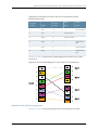
SRX Series Services Gateways Interface Cable Specifications and
Connector Pinouts . . . . . . . . . . . . . . . . . . . . . . . . . . . . . . . . . . . . . . . . . . . . . . . . 167
1-Port T1/E1 Mini-Physical Interface Module Cable Specifications . . . . . . . . . . . . 167
RJ-48 Connector to RJ-48 Connector (Straight) Pinouts for the 1-Port T1/E1
Mini-Physical Interface Module . . . . . . . . . . . . . . . . . . . . . . . . . . . . . . . . 167
RJ-48 Connector to RJ-48 Connector (Crossover) Pinouts for the 1-Port
T1/E1 Mini-Physical Interface Module . . . . . . . . . . . . . . . . . . . . . . . . . . . 168
RJ-48 Connector to DB-15 Connector (Straight) Pinouts for the 1-Port T1/E1
Mini-Physical Interface Module . . . . . . . . . . . . . . . . . . . . . . . . . . . . . . . . 169
RJ-48 Connector to DB-15 Connector (Crossover) Pinouts for the 1-Port
T1/E1 Mini-Physical Interface Module . . . . . . . . . . . . . . . . . . . . . . . . . . . 170
1-Port ADSL2+ Mini-Physical Interface Module Cable Specifications . . . . . . . . . . 171
RJ-11 Connector Pinouts for the 1-Port ADSL2+ Mini-Physical Interface
Module . . . . . . . . . . . . . . . . . . . . . . . . . . . . . . . . . . . . . . . . . . . . . . . . . . . . 171
1-Port Serial Mini-Physical Interface Module Cable Specifications . . . . . . . . . . . . 172
EIA-530A DCE Cable Pinouts for the 1-Port Serial Mini-Physical Interface
Module . . . . . . . . . . . . . . . . . . . . . . . . . . . . . . . . . . . . . . . . . . . . . . . . . . . . 172
EIA-530A DTE Cable Pinouts for the 1-Port Serial Mini-Physical Interface
Module . . . . . . . . . . . . . . . . . . . . . . . . . . . . . . . . . . . . . . . . . . . . . . . . . . . 174
RS-232 DCE Cable Pinouts for the 1-Port Serial Mini-Physical Interface
Module . . . . . . . . . . . . . . . . . . . . . . . . . . . . . . . . . . . . . . . . . . . . . . . . . . . 176
RS-232 DTE Cable Pinouts for the 1-Port Serial Mini-Physical Interface
Module . . . . . . . . . . . . . . . . . . . . . . . . . . . . . . . . . . . . . . . . . . . . . . . . . . . . 177
RS-422/449 (EIA-449) DCE Cable Pinouts for the 1-Port Serial Mini-Physical
Interface Module . . . . . . . . . . . . . . . . . . . . . . . . . . . . . . . . . . . . . . . . . . . . 178
RS-422/449 (EIA-449) DTE Cable Pinouts for the 1-Port Serial Mini-Physical
Interface Module . . . . . . . . . . . . . . . . . . . . . . . . . . . . . . . . . . . . . . . . . . . 180
V.35 DCE Cable Pinouts for the 1-Port Serial Mini-Physical Interface
Module . . . . . . . . . . . . . . . . . . . . . . . . . . . . . . . . . . . . . . . . . . . . . . . . . . . 182
V.35 DTE Cable Pinouts for the 1-Port Serial Mini-Physical Interface
Module . . . . . . . . . . . . . . . . . . . . . . . . . . . . . . . . . . . . . . . . . . . . . . . . . . . 184
X.21 DCE Cable Pinouts for the 1-Port Serial Mini-Physical Interface
Module . . . . . . . . . . . . . . . . . . . . . . . . . . . . . . . . . . . . . . . . . . . . . . . . . . . 185
X.21 DTE Cable Pinouts for the 1-Port Serial Mini-Physical Interface
Module . . . . . . . . . . . . . . . . . . . . . . . . . . . . . . . . . . . . . . . . . . . . . . . . . . . 186
1-Port G.SHDSL Mini-Physical Interface Module Cable Specifications . . . . . . . . . 187
1-Port G.SHDSL 8-Wire Mini-PIM Wire Modes . . . . . . . . . . . . . . . . . . . . . . . . 188
RJ-45 Cable (RJ-45 to Four RJ-11 Connectors) Pin Assignment . . . . . . . . . . 189
RJ-45 Cable (RJ-45 to Two RJ-11 Connectors) Pin Assignment . . . . . . . . . . 190
x
Copyright © 2012, Juniper Networks, Inc.
Table of Contents
Standard RJ-45 Cable Pin Assignment . . . . . . . . . . . . . . . . . . . . . . . . . . . . . . 191
1-Port VDSL2 (Annex A) Mini-Physical Interface Module Cable
Specifications . . . . . . . . . . . . . . . . . . . . . . . . . . . . . . . . . . . . . . . . . . . . . . . . . 192
8-Port Serial Gigabit-Backplane Physical Interface Module Cable
Specifications . . . . . . . . . . . . . . . . . . . . . . . . . . . . . . . . . . . . . . . . . . . . . . . . . 193
EIA-449 DCE Cable Pinouts for 8-Port Serial Gigabit-Backplane Physical
Interface Module . . . . . . . . . . . . . . . . . . . . . . . . . . . . . . . . . . . . . . . . . . . 194
EIA-449 DTE Cable Pinouts for 8-Port Serial Gigabit-Backplane Physical
Interface Module . . . . . . . . . . . . . . . . . . . . . . . . . . . . . . . . . . . . . . . . . . . 199
EIA-530A DCE Cable Pinouts for 8-Port Serial Gigabit-Backplane Physical
Interface Module . . . . . . . . . . . . . . . . . . . . . . . . . . . . . . . . . . . . . . . . . . . 202
EIA-530A DTE Cable Pinouts for 8-Port Serial Gigabit-Backplane Physical
Interface Module . . . . . . . . . . . . . . . . . . . . . . . . . . . . . . . . . . . . . . . . . . . 206
EIA-530 DCE Cable Pinouts for 8-Port Serial Gigabit-Backplane Physical
Interface Module . . . . . . . . . . . . . . . . . . . . . . . . . . . . . . . . . . . . . . . . . . . 210
EIA-530 DTE Cable Pinouts for 8-Port Serial Gigabit-Backplane Physical
Interface Module . . . . . . . . . . . . . . . . . . . . . . . . . . . . . . . . . . . . . . . . . . . . 214
RS-232 DCE Cable Pinouts for 8-Port Serial Gigabit-Backplane Physical
Interface Module . . . . . . . . . . . . . . . . . . . . . . . . . . . . . . . . . . . . . . . . . . . . 218
RS-232 DTE Cable Pinouts for 8-Port Serial Gigabit-Backplane Physical
Interface Module . . . . . . . . . . . . . . . . . . . . . . . . . . . . . . . . . . . . . . . . . . . 220
V.35 DCE Cable Pinouts for 8-Port Serial Gigabit-Backplane Physical
Interface Module . . . . . . . . . . . . . . . . . . . . . . . . . . . . . . . . . . . . . . . . . . . 222
V.35 DTE Cable Pinouts for 8-Port Serial Gigabit-Backplane Physical
Interface Module . . . . . . . . . . . . . . . . . . . . . . . . . . . . . . . . . . . . . . . . . . . 226
X.21 DCE Cable Pinouts for 8-Port Serial Gigabit-Backplane Physical
Interface Module . . . . . . . . . . . . . . . . . . . . . . . . . . . . . . . . . . . . . . . . . . . 229
X.21 DTE Cable Pinouts for 8-Port Serial Gigabit-Backplane Physical
Interface Module . . . . . . . . . . . . . . . . . . . . . . . . . . . . . . . . . . . . . . . . . . . 232
Appendix B
Contacting Customer Support and Returning SRX Series Services Gateway
Hardware Components . . . . . . . . . . . . . . . . . . . . . . . . . . . . . . . . . . . . . . . . . . . 235
Return Procedure for SRX Series Services Gateway Hardware Components . . . 235
Locating the SRX Series Services Gateway Hardware Component Mini-PIM or
GPIM Serial Number Label . . . . . . . . . . . . . . . . . . . . . . . . . . . . . . . . . . . . . . . 236
SRX Series Services Gateway Mini-PIM Serial Number Label . . . . . . . . . . . 236
SRX Series Services Gateway GPIM Serial Number Label . . . . . . . . . . . . . . 236
Information You Might Need to Supply to JTAC . . . . . . . . . . . . . . . . . . . . . . . . . . 237
Contacting Customer Support . . . . . . . . . . . . . . . . . . . . . . . . . . . . . . . . . . . . . . . . 237
Packing the Hardware Components for Shipment . . . . . . . . . . . . . . . . . . . . . . . . 238
Part 5
Index
Index . . . . . . . . . . . . . . . . . . . . . . . . . . . . . . . . . . . . . . . . . . . . . . . . . . . . . . . . . . . . 241
Copyright © 2012, Juniper Networks, Inc.
xi
SRX Series Services Gateways for the Branch Physical Interface Modules Hardware Guide
xii
Copyright © 2012, Juniper Networks, Inc.
About This Guide
•
Objectives on page xiii
•
Audience on page xiii
•
Documentation Conventions on page xiii
•
SRX Series Documentation and Release Notes on page xv
•
Obtaining Documentation on page xv
•
Documentation Feedback on page xvi
•
Requesting Technical Support on page xvi
Objectives
This guide describes hardware components and installation, basic configuration, and
basic troubleshooting procedures for the Juniper Networks SRX Series Services Gateway
interfaces. It explains how to prepare your site for services gateway installation, unpack
and install the hardware, power on the services gateway, perform initial software
configuration, and perform routine maintenance. After completing the installation and
basic configuration procedures covered in this guide, see the Junos OS configuration
guides for information about further Junos OS configuration.
Audience
This guide is designed for network administrators who are installing and maintaining
Juniper Networks SRX Series Services Gateway interfaces or preparing a site for device
installation. To use this guide, you need a broad understanding of networks and the
Internet, networking principles, and network configuration. Any detailed discussion of
these concepts is beyond the scope of this guide.
Documentation Conventions
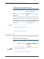
Table 1 on page xiv defines the notice icons used in this guide.
Copyright © 2012, Juniper Networks, Inc.
xiii
SRX Series Services Gateways for the Branch Physical Interface Modules Hardware Guide
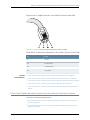
Table 1: Notice Icons
Icon
Meaning
Description
Informational note
Indicates important features or instructions.
Caution
Indicates a situation that might result in loss of data or hardware damage.
Warning
Alerts you to the risk of personal injury or death.
Laser warning
Alerts you to the risk of personal injury from a laser.
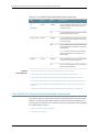
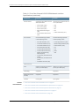
Table 2 on page xiv defines the text and syntax conventions used in this guide.
Table 2: Text and Syntax Conventions
Convention
Description
Examples
Bold text like this
Represents text that you type.
To enter configuration mode, type
theconfigure command:
user@host> configure
Fixed-width text like this
Italic text like this
Italic text like this
Text like this
< > (angle brackets)
xiv
Represents output that appears on the
terminal screen.
user@host> show chassis alarms
•
Introduces or emphasizes important
new terms.
•
•
Identifies book names.
A policy term is a named structure
that defines match conditions and
actions.
•
Identifies RFC and Internet draft titles.
•
Junos OS System Basics Configuration
Guide
•
RFC 1997, BGP Communities Attribute
No alarms currently active
Represents variables (options for which
you substitute a value) in commands or
configuration statements.
Configure the machine’s domain name:
Represents names of configuration
statements, commands, files, and
directories; configuration hierarchy levels;
or labels on routing platform
components.
•
To configure a stub area, include the
stub statement at the[edit protocols
ospf area area-id] hierarchy level.
•
The console port is labeled
CONSOLE.
Enclose optional keywords or variables.
stub <default-metric metric>;
[edit]
root@# set system domain-name
domain-name
Copyright © 2012, Juniper Networks, Inc.
About This Guide
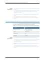
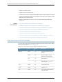
Table 2: Text and Syntax Conventions (continued)
Convention
Description
Examples
| (pipe symbol)
Indicates a choice between the mutually
exclusive keywords or variables on either
side of the symbol. The set of choices is
often enclosed in parentheses for clarity.
broadcast | multicast
# (pound sign)
Indicates a comment specified on the
same line as the configuration statement
to which it applies.
rsvp { # Required for dynamic MPLS
only
[ ] (square brackets)
Enclose a variable for which you can
substitute one or more values.
community name members [
community-ids ]
Indention and braces ( { } )
Identify a level in the configuration
hierarchy.
; (semicolon)
Identifies a leaf statement at a
configuration hierarchy level.
(string1 | string2 | string3)
[edit]
routing-options {
static {
route default {
nexthop address;
retain;
}
}
}
J-Web GUI Conventions
Bold text like this
Represents J-Web graphical user
interface (GUI) items you click or select.
> (bold right angle bracket)
Separates levels in a hierarchy of J-Web
selections.
•
In the Logical Interfaces box, select
All Interfaces.
•
To cancel the configuration, click
Cancel.
In the configuration editor hierarchy,
select Protocols>Ospf.
SRX Series Documentation and Release Notes
For a list of related SRX Series documentation, see
http://www.juniper.net/techpubs/hardware/srx-series-main.html. If the information in the
latest Junos OS Release Notes differs from the information in the documentation, follow
the Junos OS Release Notes.
Obtaining Documentation
To obtain the most current version of all Juniper Networks technical documentation, see
the products documentation page on the Juniper Networks website at
http://www.juniper.net/techpubs
To order printed copies of this guide and other Juniper Networks technical documents,
contact your sales representative.
Copies of the Management Information Bases (MIBs) available in a software release are
included on the documentation CDs and at http://www.juniper.net
Copyright © 2012, Juniper Networks, Inc.
xv
SRX Series Services Gateways for the Branch Physical Interface Modules Hardware Guide
Documentation Feedback
We encourage you to provide feedback, comments, and suggestions so that we can
improve the documentation. You can send your comments to
[email protected], or fill out the documentation feedback form at
http://www.juniper.net/techpubs/docbug/docbugreport.html. If you are using e-mail, be
sure to include the following information with your comments:
•
Document name
•
Document part number
•
Page number
•
Software release version (not required for Network Operations Guides [NOGs])
Requesting Technical Support
Technical product support is available through the Juniper Networks Technical Assistance
Center (JTAC). If you are a customer with an active J-Care or JNASC support contract,
or are covered under warranty, and need postsales technical support, you can access
our tools and resources online or open a case with JTAC.
•
JTAC policies—For a complete understanding of our JTAC procedures and policies,
review the JTAC User Guide located at
http://www.juniper.net/customers/support/downloads/710059.pdf.
•
Product warranties—For product warranty information, visit
http://www.juniper.net/support/warranty/.
•
JTAC Hours of Operation—The JTAC centers have resources available 24 hours a day,
7 days a week, 365 days a year.
Self-Help Online Tools and Resources
For quick and easy problem resolution, Juniper Networks has designed an online
self-service portal called the Customer Support Center (CSC) that provides you with the
following features:
•
Find CSC offerings: http://www.juniper.net/customers/support/
•
Find product documentation: http://www.juniper.net/techpubs/
•
Download the latest versions of software and review release notes:
http://www.juniper.net/customers/csc/software/
•
Find solutions and answer questions using our Knowledge Base: http://kb.juniper.net/
•
Search technical bulletins for relevant hardware and software notifications:
https://www.juniper.net/alerts/
xvi
Copyright © 2012, Juniper Networks, Inc.
About This Guide
•
Join and participate in the Juniper Networks Community Forum:
http://www.juniper.net/company/communities/
•
Open a case online in the CSC Case Manager: http://www.juniper.net/cm/
To verify service entitlement by product serial number, use our Serial Number Entitlement
(SNE) Tool located at https://tools.juniper.net/SerialNumberEntitlementSearch/.
Opening a Case with JTAC
You can open a case with JTAC on the Web or by telephone.
•
Use the Case Manager tool in the CSC at http://www.juniper.net/cm/ .
•
Call 1-888-314-JTAC (1-888-314-5822 toll-free in the USA, Canada, and Mexico).
For international or direct-dial options in countries without toll-free numbers, visit us at
http://www.juniper.net/support/requesting-support.html.
Copyright © 2012, Juniper Networks, Inc.
xvii
SRX Series Services Gateways for the Branch Physical Interface Modules Hardware Guide
xviii
Copyright © 2012, Juniper Networks, Inc.
PART 1
SRX Series Services Gateway Interface
Overview
•
Introduction to the SRX Series Services Gateway Interfaces on page 3
•
Installing and Removing Interfaces on the SRX Series Services Gateway on page 17
Copyright © 2012, Juniper Networks, Inc.
1
SRX Series Services Gateways for the Branch Physical Interface Modules Hardware Guide
2
Copyright © 2012, Juniper Networks, Inc.
CHAPTER 1
Introduction to the SRX Series Services
Gateway Interfaces
This chapter includes the following topics:
•
SRX Series Services Gateway Interface Overview on page 3
•
SRX Series Services Gateway Mini-Physical Interface Modules Overview on page 4
•
SRX Series Services Gateway Gigabit-Backplane Physical Interface Modules
Overview on page 5
•
Supported SRX Series Services Gateway Interfaces on page 7
•
SRX Series Services Gateway Interfaces Models and Compatibility on page 8
•
MTU Default and Maximum Values for Physical Interface Modules on page 10
•
SRX Series Services Gateway Interfaces Power and Heat Requirements on page 11
•
Power over Ethernet Support on SRX Series Services Gateway Interfaces on page 12
•
SRX Series Services Gateways Interfaces Port Naming Conventions on page 13
SRX Series Services Gateway Interface Overview
Mini-Physical Interface Modules (Mini-PIMs) and Gigabit-Backplane Physical Interface
Modules (GPIMs) are field-replaceable network interface cards (NICs) supported on the
Juniper Networks SRX Series Services Gateway for the branch. You can easily insert or
remove Mini-PIMs and GPIMs from the front slots of the SRX Series Services Gateway
chassis. The Mini-PIMs and GPIMs provide physical connections to a LAN or a WAN. The
Mini-PIMs and GPIMs receive incoming packets from the network and transmit outgoing
packets to the network. During this process, they perform framing and line-speed signaling
for the medium type. The SRX Series Services Gateways run Junos OS.
CAUTION: The Mini-PIMs available on the SRX Series Services Gateway are
not hot-swappable. You must power off the device before removing or
installing Mini-PIMs.
NOTE: Only SRX650 Services Gateway supports hot-swappable functionality
for GPIMs.
Copyright © 2012, Juniper Networks, Inc.
3
SRX Series Services Gateways for the Branch Physical Interface Modules Hardware Guide
Related
Documentation
•
SRX Series Services Gateway Mini-Physical Interface Modules Overview on page 4
•
SRX Series Services Gateway Gigabit-Backplane Physical Interface Modules Overview
on page 5
•
Supported SRX Series Services Gateway Interfaces on page 7
SRX Series Services Gateway Mini-Physical Interface Modules Overview
A Mini-Physical Interface Module (Mini-PIM) is a network interface card (NIC) that is
installed on the SRX Series Services Gateway to provide physical connections to a LAN
or a WAN. The Mini-PIM receives incoming packets from the network and transmits
outgoing packets to the network.
Table 3 on page 4 lists the Mini-PIMs and their model numbers.
Table 3: SRX Series Services Gateway Mini-PIMs Model Numbers
Mini-PIMs
Model Numbers
1-Port Small Form-Factor Pluggable (SFP)
SRX-MP-1SFP
1-Port Gigabit Ethernet Small Form-Factor
Pluggable (SFP)
SRX-MP-1SFP-GE
ADSL2+
SRX-MP-1ADSL2-A (Annex A)
SRX-MP-1ADSL2-B (Annex B)
DOCSIS
SRX-MP-1DOCSIS3
G.SHDSL
SRX-MP-8GSHDSL
Serial
SRX-MP-1Serial
T1/E1
SRX-MP-1T1E1
VDSL2 (Annex A)
SRX-MP-1VDSL2-A (Annex A)
The Mini-PIMs supported on the SRX Series Services Gateway are field-replaceable. You
can install a Mini-PIM into the Mini-PIM slot on the front panel of the services gateway
chassis.
CAUTION: The Mini-PIMs available on the SRX Series Services Gateway are
not hot-swappable. You must power off the device before removing or
installing Mini-PIMs.
Related
Documentation
4
•
Supported SRX Series Services Gateway Interfaces on page 7
•
SRX Series Services Gateway Interfaces Models and Compatibility on page 8
Copyright © 2012, Juniper Networks, Inc.
Chapter 1: Introduction to the SRX Series Services Gateway Interfaces
•
SRX Series Services Gateway Interfaces Power and Heat Requirements on page 11
•
SRX Series Services Gateways Interfaces Port Naming Conventions on page 13
SRX Series Services Gateway Gigabit-Backplane Physical Interface Modules Overview
A Gigabit-Backplane Physical Interface Module (GPIM) is a network interface card (NIC)
that installs in the front slots of the SRX550 or SRX650 Services Gateway to provide
physical connections to a LAN or a WAN. The GPIM receives incoming packets from a
network and transmits outgoing packets to a network. These modules will complement
the onboard Ethernet interfaces to extend the types and port counts of network
connections for the LAN or WAN.
Interface module terminology:
•
GPIM—Network interface card (NIC) that installs in a single-high, single-wide GPIM
front slots of the SRX550 Services Gateway and the SRX650 Services Gateway that
have Gigabit connectivity to the system backplane.
•
XPIM (10-Gigabit Ethernet GPIM)—Can be installed:
•
SRX550 Services Gateway—in the 10-Gigabit GPIM slot 3 or in the 20-Gigabit GPIM
slot 6 on the front panel
•
SRX650 Services Gateway—in the 20-Gigabit GPIM slots (slots 2 and 6 on the front
panel)
It can have one of the following configurations:
•
Single-high, single-wide LAN switch GPIM that uses one slot
•
Double-high, single-wide LAN switch GPIM that uses two standard slots vertically
•
Double-high, double-wide LAN switch GPIM that uses two standard slots vertically
and two standard slots horizontally
NOTE: When installing the 24-Port Gigabit Ethernet XPIM, which uses four
slots, you must install it in the 20-Gigabit GPIM slots:
•
SRX550 Services Gateway—Slot 6 among the top four standard slots
(slots 5 through 8).
•
SRX650 Services Gateway—Slot 2 among the bottom four standard
slots (slots 1 through 4), and slot 6 among the top four standard slots
(slots 5 through 8).
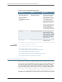
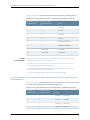
Table 4 on page 6 lists the GPIMs and XPIMs and their respective model numbers.
Copyright © 2012, Juniper Networks, Inc.
5
SRX Series Services Gateways for the Branch Physical Interface Modules Hardware Guide
Table 4: SRX Series Services Gateway GPIM and XPIM Model Numbers
GPIM or XPIM
Model Number
Dual CT1/E1 GPIM
SRX-GP-DUAL-T1-E1
Quad CT1/E1 GPIM
SRX-GP-QUAD-T1-E1
1-Port Clear Channel DS3/E3 GPIM
SRX-GP-1DS3-E3
2-Port 10 Gigabit Ethernet XPIM
SRX-GP-2XE-SFPP-TX
8-Port Serial GPIM
SRX-GP-8SERIAL
16-Port Gigabit Ethernet XPIM
16-Port Gigabit Ethernet XPIM (with PoE)
SRX-GP-16GE
SRX-GP-16GE-POE
24-Port Gigabit Ethernet XPIM
24-Port Gigabit Ethernet XPIM (with PoE)
SRX-GP-24GE
SRX-GP-24GE-POE
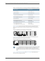
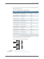
Figure 1 on page 6 shows how the slots on the front panel of the SRX550 Services
Gateway are numbered. Slots 1 and 2 are for Mini-PIMs, and slots 3 through 8 are for
GPIMs.
Figure 1: SRX550 Services Gateway Slot Numbers
7
8
5
6
2
4
3
g034104
1
Figure 2 on page 6 shows how the slots on the front panel of the SRX650 Services
Gateway are numbered. Slots 1 through 8 are for GPIMs.
650
7
5
3
1
8
6
4
2
g032701
Figure 2: SRX650 Services Gateway Slot Numbers
NOTE: Only SRX650 Services Gateway supports hot-swappable functionality
for GPIMs. Because the services gateway GPIMs communicate with the
backplane at various performance levels, you must install them in the correct
slots.
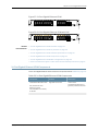
Figure 3 on page 7, Figure 4 on page 7, and Figure 5 on page 7 show the three form
factors for the services gateway GPIMs.
6
Copyright © 2012, Juniper Networks, Inc.
Chapter 1: Introduction to the SRX Series Services Gateway Interfaces
g032721
Figure 3: Example of a Standard GPIM (Installs in One Standard Slot)
g032723
Figure 4: Example of a Double-High, Single-Wide XPIM
g032724
Figure 5: Example of a Double-High, Double-Wide XPIM
Related
Documentation
•
Required Tools and Parts for Replacing a Gigabit-Backplane Physical Interface Module
on page 22
•
Removing a Blank Gigabit-Backplane Physical Interface Module Faceplate from the
SRX Series Services Gateway on page 24
•
Installing a Gigabit-Backplane Physical Interface Module on the SRX Series Services
Gateway on page 24
•
Installing a Double-High, Double-Wide Gigabit-Backplane Physical Interface Module
on the SRX Series Services Gateway on page 27
Supported SRX Series Services Gateway Interfaces
The SRX Series Services Gateways support the following Mini-Physical Interface Modules
(Mini-PIMs):
•
1-Port Small Form-Factor Pluggable (SFP)
•
1-Port Gigabit Ethernet Small Form-Factor Pluggable (SFP)
•
ADSL2+
•
DOCSIS
•
G.SHDSL
•
Serial
Copyright © 2012, Juniper Networks, Inc.
7
SRX Series Services Gateways for the Branch Physical Interface Modules Hardware Guide
•
T1/E1
•
VDSL2
The SRX Series Services Gateways support the following Gigabit-Backplane Physical
Interface Modules (GPIMs/XPIMs):
Related
Documentation
•
Dual CT1/E1 GPIM
•
Quad CT1/E1 GPIM
•
1-Port Clear Channel DS3/E3 GPIM
•
2-Port 10 Gigabit Ethernet XPIM
•
8-Port Serial GPIM
•
16-Port Gigabit Ethernet XPIM (with PoE)
•
24-Port Gigabit Ethernet XPIM (with PoE)
•
SRX Series Services Gateway Mini-Physical Interface Modules Overview on page 4
•
SRX Series Services Gateway Gigabit-Backplane Physical Interface Modules Overview
on page 5
•
SRX Series Services Gateway Interfaces Models and Compatibility on page 8
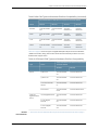
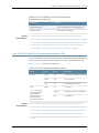
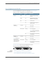
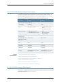
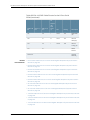
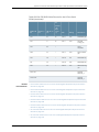
SRX Series Services Gateway Interfaces Models and Compatibility
Table 5 on page 8 shows the types of Mini-Physical Interface Modules (Mini-PIMs) with
the SRX Series devices and the Junos OS releases that support them.
Table 5: Mini-PIM Types and Hardware Platform Compatibility
Supported Platforms and Minimum Supported Junos OS Release
8
Name
SRX210
SRX220
SRX240
SRX550
1-Port Small
Form-Factor
Pluggable
(SFP)
Junos OS Release
9.4
Not Supported
Junos OS
Release 9.4
Not Supported
1-Port Gigabit
Ethernet
Small
Form-Factor
Pluggable
(SFP)
Junos OS Release
10.4
Junos OS Release
10.4
Junos OS
Release 10.4
Junos OS
Release 12.1
ADSL2+
Junos OS Release
9.5
Junos OS Release
10.3
Junos OS
Release 9.5
Junos OS
Release 12.1
DOCSIS
Junos OS Release
10.1
Junos OS Release
10.3
Junos OS
Release 10.1
Junos OS
Release 12.1
Copyright © 2012, Juniper Networks, Inc.
Chapter 1: Introduction to the SRX Series Services Gateway Interfaces
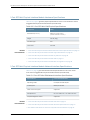
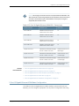
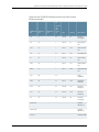
Table 5: Mini-PIM Types and Hardware Platform Compatibility (continued)
Supported Platforms and Minimum Supported Junos OS Release
Name
SRX210
SRX220
SRX240
SRX550
G.SHDSL
Junos OS Release
10.0
Junos OS Release
10.3
Junos OS
Release 10.0
Junos OS
Release 12.1
Serial
Junos OS Release
9.5
Junos OS Release
10.3
Junos OS
Release 9.5
Junos OS
Release 12.1
T1/E1
Junos OS Release
9.4
Junos OS Release
10.3
Junos OS
Release 9.4
Junos OS
Release 12.1
VDSL2
Junos OS Release
10.1
Junos OS Release
10.3
Junos OS
Release 10.1
Junos OS
Release 12.1
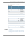
Table 6 on page 9 shows the types of Gigabit-Backplane Physical Interface Modules
(GPIMs and XPIMs), along with the SRX Series Services Gateways and the Junos OS
Releases that support them.
Table 6: GPIM and XPIM Types and Hardware Platform Compatibility
Type
GPIMs
XPIMs (10
Gigabit Ethernet
GPIM)
Related
Documentation
•
Name
Supported Platforms and Minimum Supported
Junos OS Release
SRX650
SRX550
Dual CT1/E1
Junos OS Release
9.5
Junos OS Release 12.1
Quad CT1/E1
Junos OS Release
9.5
Junos OS Release 12.1
1-Port Clear Channel
DS3/E3
Junos OS Release
11.1
Junos OS Release 12.1
8-Port Serial
Junos OS Release
12.1R2
Junos OS Release 12.1R2
16-Port Gigabit Ethernet
Junos OS Release
9.5
Junos OS Release 12.1
24-Port Gigabit
Ethernet
Junos OS Release
9.5
Junos OS Release 12.1
2-Port 10 Gigabit
Ethernet
Junos OS Release
10.2
Junos OS Release 12.1
SRX Series Services Gateway Mini-Physical Interface Modules Overview on page 4
Copyright © 2012, Juniper Networks, Inc.
9
SRX Series Services Gateways for the Branch Physical Interface Modules Hardware Guide
•
SRX Series Services Gateway Gigabit-Backplane Physical Interface Modules Overview
on page 5
•
Supported SRX Series Services Gateway Interfaces on page 7
•
SRX Series Services Gateway Interfaces Power and Heat Requirements on page 11
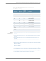
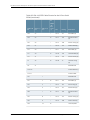
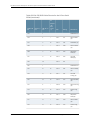
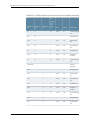
MTU Default and Maximum Values for Physical Interface Modules
Table 7 on page 10 lists maximum transmission unit (MTU) values for the SRX Series
Services Gateways Physical Interface Modules (PIMs).
Table 7: MTU Values for the SRX Series Services Gateways PIMs
Physical
Interface MTU
(Bytes)
Logical
Interface MTU
(Bytes)
Default MTU
(Bytes)
Maximum MTU
(Bytes)
1-Port Gigabit
Ethernet small
form-factor
pluggable (SFP)
Mini-PIM
1514
1500
1514
9010
1-Port small
form-factor
pluggable (SFP)
Mini-PIM
1514
1500
1514
1518
ADSL2+
Mini-PIM
1496
1456
1496
1512
DOCSIS
Mini-PIM
1504
1500
1504
1504
G.SHDSL
Mini-PIM
1496
1468
1496
4482
Serial Mini-PIM
1504
1500
1504
2000
T1/E1 Mini-PIM
1504
1500
1504
2000
VDSL2 Mini-PIM
1496
1482
1496
1496
Dual CT1/E1
GPIM
1504
1500
1504
9000
Quad CT1/E1
GPIM
1504
1500
1504
9000
8-Port Serial
GPIM
1504
1500
1504
9192
PIM
10
Copyright © 2012, Juniper Networks, Inc.
Chapter 1: Introduction to the SRX Series Services Gateway Interfaces
Table 7: MTU Values for the SRX Series Services Gateways
PIMs (continued)
Physical
Interface MTU
(Bytes)
Logical
Interface MTU
(Bytes)
Default MTU
(Bytes)
Maximum MTU
(Bytes)
1-Port Clear
Channel DS3/E3
1504
1500
1504
9192
2-Port 10 Gigabit
Ethernet XPIM
1514
1500
1514
9192
16-Port Gigabit
Ethernet XPIM
1514
Unspecified
1514
Unspecified
24-Port Gigabit
Ethernet XPIM
1514
Unspecified
1514
Unspecified
PIM
Related
Documentation
•
SRX Series Services Gateway Mini-Physical Interface Modules Overview on page 4
•
Supported SRX Series Services Gateway Interfaces on page 7
•
SRX Series Services Gateway Interfaces Models and Compatibility on page 8
SRX Series Services Gateway Interfaces Power and Heat Requirements
Table 8 on page 11 shows the power consumption value of each Physical Interface
Module (PIM).
Table 8: PIM Power Consumption Values
PIM Model
Power Consumption
(Watts)
1-Port small form-factor pluggable (SFP) Mini-PIM
4.29
1-Port Gigabit Ethernet small form-factor pluggable (SFP)
Mini-PIM
4.4
ADSL2+ Mini-PIM
4.11
DOCSIS Mini-PIM
7.00
G.SHDSL Mini-PIM
8.31
Serial Mini-PIM
4.29
T1/E1 Mini-PIM
1.92
VDSL2 Mini-PIM
9.80
Copyright © 2012, Juniper Networks, Inc.
11
SRX Series Services Gateways for the Branch Physical Interface Modules Hardware Guide
Table 8: PIM Power Consumption Values (continued)
Related
Documentation
PIM Model
Power Consumption
(Watts)
Dual CT1/E1 GPIM
16.81
Quad CT1/E1 GPIM
16.81
8-Port Serial GPIM
13.1
1-Port Clear Channel DS3/E3 GPIM
22.89
2-Port 10 Gigabit Ethernet XPIM
20
16-Port Gigabit Ethernet XPIM
40 (without PoE)
24-Port Gigabit Ethernet XPIM
40 (without PoE)
•
SRX Series Services Gateway Mini-Physical Interface Modules Overview on page 4
•
SRX Series Services Gateway Gigabit-Backplane Physical Interface Modules Overview
on page 5
•
Supported SRX Series Services Gateway Interfaces on page 7
•
SRX Series Services Gateway Interfaces Models and Compatibility on page 8
•
SRX Series Services Gateways Interfaces Port Naming Conventions on page 13
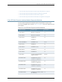
Power over Ethernet Support on SRX Series Services Gateway Interfaces
Power over Ethernet (PoE) supports the implementation of the IEEE 802.3 af and IEEE
802.3 at standards, which allow both data and electric power to pass over a copper
Ethernet LAN cable.
The SRX550 and SRX650 Services Gateways provide PoE ports, which supply electric
power over the same ports that are used for connecting network devices. PoE ports allow
you to plug in devices that require both network connectivity and electric power, such as
voice over IP (VoIP) and IP phones and wireless access points.
The PoE ports for the SRX550 and SRX650 Services Gateway reside on the individual
XPIMs. The services gateway supports the following XPIMs with PoE:
•
16-Port Gigabit Ethernet XPIM
•
24-Port Gigabit Ethernet XPIM
The active Services and Routing Engine (SRE) manages the overall system PoE power.
You can configure the services gateway to act as power sourcing equipment to supply
the power to the GPIMs connected on the designated PoE ports.
Table 9 on page 13 lists the SRX550 and SRX650 Services Gateway PoE specifications.
12
Copyright © 2012, Juniper Networks, Inc.
Chapter 1: Introduction to the SRX Series Services Gateway Interfaces
Table 9: SRX550 and SRX650 Services Gateway PoE Specifications
Power Management
Schemes
Values
Supported standards
•
IEEE 802.3 af
•
IEEE 802.3 at
•
Legacy
Supported slots
Total PoE power sourcing
capacity
Related
Documentation
PoE is supported on the following front panel slots:
•
SRX550 Services Gateway—Slots 3,4,6,8
•
SRX650 Services Gateway—Slots 2,4,6,8
The 645 W AC and 645 W DC power supplies support the
following capacities:
•
255 W with PoE on a single power supply, or with redundancy
using the two-power-supply option
•
510 W with PoE using the two-power-supply option operating
as nonredundant
Per-port power limit
31.2 W
Power management modes
•
Static: Power allocation for each interface can be configured.
•
Class: Power for interfaces is allocated based on the class of
the powered device connected.
•
SRX Series Services Gateway Gigabit-Backplane Physical Interface Modules Overview
on page 5
•
16-Port Gigabit Ethernet XPIM Overview on page 131
•
24-Port Gigabit Ethernet XPIM Overview on page 139
•
Installing a Gigabit-Backplane Physical Interface Module on the SRX Series Services
Gateway on page 24
•
Installing a Double-High, Double-Wide Gigabit-Backplane Physical Interface Module
on the SRX Series Services Gateway on page 27
SRX Series Services Gateways Interfaces Port Naming Conventions
When configuring a port on a Mini-Physical Interface Module (Mini-PIM) or
Gigabit-Backplane Physical Interface Module (GPIM), you must know the slot and port
number assigned by the system. The slot number identifies the slot on the device in which
you insert the Mini-PIM or GPIM, and is typically named 1, 2, 3, and so on. The port number
is the port on the Mini-PIM or GPIM that is being configured.
The name of each network interface has the following format to identify the physical
device that corresponds to a single physical network connector:
type-slot/pim/port
Copyright © 2012, Juniper Networks, Inc.
13
SRX Series Services Gateways for the Branch Physical Interface Modules Hardware Guide
For SRX Series Services Gateways, pim equals 0 for the port-naming convention.
Table 10 on page 14 lists the typical interface types and interface numbers.
Table 10: SRX Series Services Gateway Interface Port Number Examples
Interface Type
Interface Number Example
ATM-over-ADSL
at-1/0/0
G.SHDSL
at-1/0/0
T1
t1-1/0/0
E1
e1-1/0/0
1-Port SFP
ge-1/0/0
1-Port Gigabit Ethernet SFP
ge-1/0/0
Serial
se-1/0/0
DOCSIS
cm-1/0/0
VDSL2
pt-1/0/0
1-Port Clear Channel DS3/E3 GPIM
t3-3/0/0
16-Port Gigabit Ethernet XPIM
•
SRX550 Services Gateway—ge-3/0/0
•
SRX650 Services Gateway—ge-2/0/0
NOTE: When installing the 16-Port Gigabit
Ethernet XPIM, which uses 2 slots, you must
install it in the 10-Gigabit or 20-Gigabit GPIM
slots:
24-Port Gigabit Ethernet XPIM
•
SRX550 Services Gateway—Slot 3 for
10-Gigabit GPIM and slot 6 for 20-Gigabit
GPIM.
•
SRX650 Services Gateway—Slots 2 and 6.
•
SRX550 Services Gateway—ge-6/0/0
•
SRX650 Services Gateway—ge-2/0/0
NOTE: When installing the 24-Port Gigabit
Ethernet XPIM, which uses 4 slots, you must
install it in the 20-Gigabit GPIM slots:
14
•
SRX550 Services Gateway—Slot 6.
•
SRX650 Services Gateway—Slots 2 and 6.
Copyright © 2012, Juniper Networks, Inc.
Chapter 1: Introduction to the SRX Series Services Gateway Interfaces
Table 10: SRX Series Services Gateway Interface Port Number
Examples (continued)
Interface Type
Interface Number Example
2-Port 10 Gigabit Ethernet XPIM
•
SRX550 Services Gateway—xe-3/0/0
•
SRX650 Services Gateway—xe-2/0/0,
xe-2/0/1, or
xe-6/0/0, xe-6/0/1
NOTE: Represents two fiber and two copper
ports; user configured. Must be installed in one
of the following GPIM slots:
Related
Documentation
•
SRX550 Services Gateway—Slot 3 for
10-Gigabit GPIM and slot 6 for 20-Gigabit
GPIM.
•
SRX650 Services Gateway—Slots 2 or 6.
Dual CT1/E1 GPIM
ct1-1/0/0
ce1-1/0/0
Quad CT1/E1 GPIM
ct1-1/0/0
ce1-1/0/0
8-Port Serial GPIM
se-1/0/0 to se-1/0/7
•
Installing a Double-High, Double-Wide Gigabit-Backplane Physical Interface Module
on the SRX Series Services Gateway on page 27
•
SRX Series Services Gateway Mini-Physical Interface Modules Overview on page 4
•
SRX Series Services Gateway Gigabit-Backplane Physical Interface Modules Overview
on page 5
•
Supported SRX Series Services Gateway Interfaces on page 7
•
SRX Series Services Gateway Interfaces Models and Compatibility on page 8
•
SRX Series Services Gateway Interfaces Power and Heat Requirements on page 11
Copyright © 2012, Juniper Networks, Inc.
15
SRX Series Services Gateways for the Branch Physical Interface Modules Hardware Guide
16
Copyright © 2012, Juniper Networks, Inc.
CHAPTER 2
Installing and Removing Interfaces on the
SRX Series Services Gateway
This chapter includes the following topics:
•
Replacing a Mini-Physical Interface Module in the SRX Series Services
Gateway on page 17
•
Replacing a Gigabit-Backplane Physical Interface Module in the SRX Series Services
Gateway on page 22
Replacing a Mini-Physical Interface Module in the SRX Series Services Gateway
This topic includes the following sections:
•
Required Tools and Parts for Replacing a Mini-Physical Interface Module on page 17
•
Removing a Blank Mini-Physical Interface Module Faceplate from the SRX Series
Services Gateway on page 18
•
Installing a Mini-Physical Interface Module in the SRX Series Services
Gateway on page 19
•
Removing a Mini-Physical Interface Module from the SRX Series Services
Gateway on page 20
Required Tools and Parts for Replacing a Mini-Physical Interface Module
The following tools and parts are required for replacing Mini-Physical Interface Modules
(Mini-PIMs) on the SRX Series Services Gateway:
Related
Documentation
•
Electrostatic bag or antistatic mat, for each component
•
Electrostatic discharge (ESD) grounding wrist strap
•
Flat blade (–) screwdriver, approximately 1/8 in. (3 mm)
•
Phillips (+) screwdrivers, number 1
•
Removing a Blank Mini-Physical Interface Module Faceplate from the SRX Series
Services Gateway on page 18
•
Installing a Mini-Physical Interface Module in the SRX Series Services Gateway on
page 19
Copyright © 2012, Juniper Networks, Inc.
17
SRX Series Services Gateways for the Branch Physical Interface Modules Hardware Guide
•
Removing a Mini-Physical Interface Module from the SRX Series Services Gateway on
page 20
•
SRX Series Services Gateway Mini-Physical Interface Modules Overview on page 4
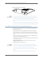
Removing a Blank Mini-Physical Interface Module Faceplate from the SRX Series Services
Gateway
To maintain proper airflow through the services gateway, a blank faceplate should cover
any empty Mini-Physical Interface Module (Mini-PIM) slot.
CAUTION: Do not remove a blank faceplate unless you are installing a
Mini-PIM in the empty slot.
CAUTION: The Mini-PIMs available on the SRX Series Services Gateway are
not hot-swappable. You must power off the device before removing or
installing Mini-PIMs.
To remove a blank faceplate from the SRX Series Services Gateway:
1.
Attach an electrostatic discharge (ESD) grounding strap to your bare wrist, and connect
the strap to the ESD point on the device.
2. If the device is powered on, power off the device. Verify that the Power LED is off.
3. Loosen the screws on each side of the faceplate.
•
On faceplates with handles, use a 1/8-in. (3-mm) flat-blade (–) screwdriver to
loosen but not remove the captive screws.
•
On faceplates without handles, use a number 1 Phillips screwdriver to remove the
noncaptive screws.
4. Remove the faceplate. See Figure 6 on page 18.
Figure 6: Removing a Blank Mini-PIM Faceplate from an SRX Series
Services Gateway
18
Copyright © 2012, Juniper Networks, Inc.
Chapter 2: Installing and Removing Interfaces on the SRX Series Services Gateway
Related
Documentation
•
Required Tools and Parts for Replacing a Mini-Physical Interface Module on page 17
•
Installing a Mini-Physical Interface Module in the SRX Series Services Gateway on
page 19
•
Removing a Mini-Physical Interface Module from the SRX Series Services Gateway on
page 20
•
SRX Series Services Gateway Mini-Physical Interface Modules Overview on page 4
Installing a Mini-Physical Interface Module in the SRX Series Services Gateway
CAUTION: The Mini-PIMs available on the SRX Series Services Gateway are
not hot-swappable. You must power off the device before removing or
installing Mini-PIMs.
To install a Mini-Physical Interface Module (Mini-PIM) in the SRX Series Services Gateway:
1.
Attach an electrostatic discharge (ESD) grounding strap to your bare wrist, and connect
the strap to the grounding point on the back of the device.
2. Power off the device by briefly pressing the Power button on the front panel. Wait for
the Power LED to turn off before proceeding.
3. Disconnect the device from its power source:
•
For SRX210 or SRX220 devices, either unplug the power adapter from the AC power
outlet, or disconnect the power adapter from the power connector on the rear panel
of the device.
•
For SRX240 devices, either unplug the AC power cord from the AC power outlet, or
disconnect the AC power cord from the AC power connector on the rear panel of
the device.
4. Remove the Mini-PIM from the electrostatic bag.
5. Grasp the screws on each side of the Mini-PIM faceplate and align the notches in the
connector at the rear of the Mini-PIM with the notches in the Mini-PIM slot in the
device.
CAUTION: Slide the Mini-PIM straight into the slot to avoid damaging the
components on the Mini-PIM.
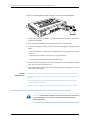
6. Slide the Mini-PIM in until it lodges firmly in the device. See Figure 7 on page 20.
Copyright © 2012, Juniper Networks, Inc.
19
SRX Series Services Gateways for the Branch Physical Interface Modules Hardware Guide
Figure 7: Installing a Mini-PIM in an SRX Series Services Gateway
7. Using a 1/8-in. (3-mm) flat-blade (–) screwdriver, tighten the screws on each side of
the Mini-PIM faceplate.
8. Insert the appropriate cables into the cable connectors on the Mini-PIM.
9. If necessary, arrange the cables to prevent them from dislodging or developing stress
points:
•
Secure the cables so that they are not supporting their own weight as they hang to
the floor.
•
Place any excess cables out of the way in neatly coiled loops.
•
Use fasteners to maintain the shape of the cable loops.
10. Reconnect the power adapter to the device. Verify that the Power LED glows steadily
green after you press the power button.
11. Verify that the Mini-PIM LED on the system dashboard glows steadily green to confirm
that the Mini-PIM is online.
Related
Documentation
•
Required Tools and Parts for Replacing a Mini-Physical Interface Module on page 17
•
Removing a Mini-Physical Interface Module from the SRX Series Services Gateway on
page 20
•
Removing a Blank Mini-Physical Interface Module Faceplate from the SRX Series
Services Gateway on page 18
•
SRX Series Services Gateway Mini-Physical Interface Modules Overview on page 4
Removing a Mini-Physical Interface Module from the SRX Series Services Gateway
CAUTION: The Mini-PIMs available on the SRX Series Services Gateway are
not hot-swappable. You must power off the device before removing or
installing Mini-PIMs.
20
Copyright © 2012, Juniper Networks, Inc.
Chapter 2: Installing and Removing Interfaces on the SRX Series Services Gateway
To remove a Mini-PIM from the SRX Series Services Gateway:
1.
Place an electrostatic bag or antistatic mat on a flat, stable surface on which you
intend to place the Mini-PIM.
2. Attach an ESD grounding strap to your bare wrist, and connect the strap to the
grounding point on the back of the device.
3. Unplug the power adapter from the device. Verify that the Power LED is off.
4. Label the cables connected to the Mini-PIM so that you can later reconnect each
cable to the correct Mini-PIM.
5. Disconnect the cables from the Mini-PIM.
6. If necessary, arrange the cables to prevent them from dislodging or developing stress
points.
7. Remove the screws on each side of the Mini-PIM faceplate using a screwdriver.
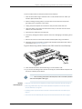
8. Grasp the screws on each side of the Mini-PIM faceplate and slide the Mini-PIM out
of the device. See Figure 8 on page 21.
Figure 8: Removing a Mini-PIM from the SRX Series Services Gateway
9. Place the Mini-PIM in the electrostatic bag or on the antistatic mat.
10. If you are not reinstalling a Mini-PIM into the empty slot, install a blank faceplate over
the slot to maintain proper airflow.
NOTE: When installing a blank Mini-PIM faceplate, make sure that the padded
side of the faceplate is facing up.
Related
Documentation
•
Required Tools and Parts for Replacing a Mini-Physical Interface Module on page 17
•
Removing a Blank Mini-Physical Interface Module Faceplate from the SRX Series
Services Gateway on page 18
•
Installing a Mini-Physical Interface Module in the SRX Series Services Gateway on
page 19
•
SRX Series Services Gateway Mini-Physical Interface Modules Overview on page 4
Copyright © 2012, Juniper Networks, Inc.
21
SRX Series Services Gateways for the Branch Physical Interface Modules Hardware Guide
Replacing a Gigabit-Backplane Physical Interface Module in the SRX Series Services
Gateway
This topic includes the following sections:
•
Required Tools and Parts for Replacing a Gigabit-Backplane Physical Interface
Module on page 22
•
Preventing Electrostatic Discharge Damage to the SRX Series Services
Gateway on page 23
•
Removing a Blank Gigabit-Backplane Physical Interface Module Faceplate from the
SRX Series Services Gateway on page 24
•
Installing a Gigabit-Backplane Physical Interface Module on the SRX Series Services
Gateway on page 24
•
Installing a Double-High, Double-Wide Gigabit-Backplane Physical Interface Module
on the SRX Series Services Gateway on page 27
•
Removing a Gigabit-Backplane Physical Interface Module from the SRX Series Services
Gateway on page 28
Required Tools and Parts for Replacing a Gigabit-Backplane Physical Interface Module
The following tools and parts are required for replacing a Gigabit-Backplane Physical
Interface Module (GPIM) on the SRX Series Services Gateway:
Related
Documentation
22
•
Electrostatic bag or antistatic mat, for each component
•
Electrostatic discharge (ESD) grounding wrist strap
•
Flat-blade (–) screwdriver, approximately 1/8 in. (3 mm)
•
Phillips (+) screwdrivers, numbers 1 and 2
•
Blank panels (if no component is installed)
•
Removing a Blank Gigabit-Backplane Physical Interface Module Faceplate from the
SRX Series Services Gateway on page 24
•
Installing a Gigabit-Backplane Physical Interface Module on the SRX Series Services
Gateway on page 24
•
Installing a Double-High, Double-Wide Gigabit-Backplane Physical Interface Module
on the SRX Series Services Gateway on page 27
•
Removing a Gigabit-Backplane Physical Interface Module from the SRX Series Services
Gateway on page 28
Copyright © 2012, Juniper Networks, Inc.
Chapter 2: Installing and Removing Interfaces on the SRX Series Services Gateway
Preventing Electrostatic Discharge Damage to the SRX Series Services Gateway
Many services gateway hardware components are sensitive to damage from static
electricity. Some components can be impaired by voltages as low as 30 V. You can easily
generate potentially damaging static voltages whenever you handle plastic or foam
packing material or if you move components across plastic or carpets. Observe the
following guidelines to minimize the potential for electrostatic discharge (ESD) damage,
which can cause intermittent or complete component failures:
•
Always use an ESD wrist strap or ankle strap, and verify that it is in direct contact with
your skin.
CAUTION: For safety, periodically check the resistance value of the ESD
strap. The measurement should be in the range of 1 to 10 Mohms.
•
When handling any component that is removed from the chassis, verify that the
equipment end of your ESD strap is attached to one of the ESD points on the chassis.
•
Avoid contact between the component and your clothing. ESD voltages emitted from
clothing can damage components.
•
When removing or installing a component, always place it component-side up on an
antistatic surface, in an antistatic card rack, or in an electrostatic bag. See Figure 9 on
page 23. If you are returning a component, place it into an electrostatic bag before
packing it.
Figure 9: Placing a Component into an Electrostatic Bag
Related
Documentation
•
Installing a Gigabit-Backplane Physical Interface Module on the SRX Series Services
Gateway on page 24
•
Removing a Gigabit-Backplane Physical Interface Module from the SRX Series Services
Gateway on page 28
Copyright © 2012, Juniper Networks, Inc.
23
SRX Series Services Gateways for the Branch Physical Interface Modules Hardware Guide
Removing a Blank Gigabit-Backplane Physical Interface Module Faceplate from the SRX Series
Services Gateway
To maintain proper airflow through the services gateway, leave blank faceplates in place
over slots that do not contain Gigabit-Backplane Physical Interface Modules (GPIMs).
Do not remove a blank faceplate unless you are installing a GPIM in the empty slot.
To remove a blank faceplate:
1.
Using a Phillips (+) screwdriver, loosen the captive screws on each side of the blank
faceplate.
2. Using a flat-blade (–) screwdriver, gently pry out one side of the faceplate and pull
it off.
NOTE: When installing a blank GPIM faceplate, make sure that the padded
side of the faceplate is facing up.
Related
Documentation
•
Installing a Gigabit-Backplane Physical Interface Module on the SRX Series Services
Gateway on page 24
•
Installing a Double-High, Double-Wide Gigabit-Backplane Physical Interface Module
on the SRX Series Services Gateway on page 27
•
Removing a Gigabit-Backplane Physical Interface Module from the SRX Series Services
Gateway on page 28
•
Required Tools and Parts for Replacing a Gigabit-Backplane Physical Interface Module
on page 22
Installing a Gigabit-Backplane Physical Interface Module on the SRX Series Services Gateway
NOTE: Only SRX650 Services Gateway supports hot-swappable functionality
for GPIMs. Ensure that the GPIM is installed in the appropriate GPIM slot. For
more information about the appropriate GPIM slots, see “SRX Series Services
Gateway Gigabit-Backplane Physical Interface Modules Overview” on page 5.
24
Copyright © 2012, Juniper Networks, Inc.
Chapter 2: Installing and Removing Interfaces on the SRX Series Services Gateway
NOTE: To maintain proper airflow through the services gateway, leave blank
faceplates in place over slots that do not contain GPIMs. Do not remove a
blank faceplate unless you are installing a GPIM in the empty slot. If you need
to remove a blank faceplate to install the new GPIM into this slot, see
“Removing a Blank Gigabit-Backplane Physical Interface Module Faceplate
from the SRX Series Services Gateway” on page 24.
NOTE: Installing a GPIM on the SRX550 Services Gateway is similar to
installing a GPIM on the SRX650 Services Gateway.
To install a GPIM:
1.
Attach an electrostatic discharge (ESD) grounding strap to your bare wrist, and connect
the strap to one of the ESD points on the chassis. For more information about ESD,
see “Preventing Electrostatic Discharge Damage to the SRX Series Services Gateway”
on page 23.
2. Grasp the handles on each side of the GPIM faceplate, and align the edges of the
GPIM circuit board with the guide rails at each side of the GPIM slot.
NOTE: If you are installing a double-high, double-wide GPIM such as the
24-Port Ethernet XPIM, you must remove the center GPIM slot bracket.
3. Slide the GPIM into the services gateway until it seats firmly in the device.
CAUTION: Slide the GPIM straight into the slot to avoid damaging the
components on the GPIM.
Figure 10: Installing a Double-High, Single-Wide GPIM in an SRX650
Services Gateway
g032731
650
4. Using a Phillips (+) screwdriver, tighten the captive screws on each side of the GPIM
faceplate.
Copyright © 2012, Juniper Networks, Inc.
25
SRX Series Services Gateways for the Branch Physical Interface Modules Hardware Guide
5. Insert the appropriate cables into the cable connectors on the GPIM.
6. If necessary, arrange the cables to prevent them from dislodging or developing stress
points:
•
Secure the cable so that it is not supporting its own weight as it hangs to the floor.
•
Place excess cable out of the way in a neatly coiled loop.
•
Use fasteners to maintain the shape of the cable loops.
After the STATUS LED light turns green and glows steadily on, the GPIM is considered
online and functioning normally. See Figure 11 on page 26 and Table 11 on page 26 for
hot-swappable components and their descriptions.
NOTE: Only SRX650 Services Gateway supports hot-swappable functionality
for GPIMs.
2
1
g032737
Figure 11: GPIM Example with Hot-Swappable Components
Table 11: Hot-Swappable Component Descriptions for GPIMs
Number
Component
Description
1
STATUS LED
The STATUS LED has the following indicator colors:
2
Related
Documentation
26
ONLINE/OFFLINE
button
•
Green and steadily on indicates that the GPIM is
functioning normally.
•
Amber and steadily on indicates that the GPIM is starting
up, running diagnostics, or going offline.
•
Red and steadily on indicates that the GPIM has failed.
•
Off indicates that the GPIM is not powered on, is offline,
or is not configured.
NOTE: You are not required to press this button when
installing a GPIM. The services gateway automatically
recognizes when a GPIM has been inserted into its slots.
•
Removing a Gigabit-Backplane Physical Interface Module from the SRX Series Services
Gateway on page 28
•
Required Tools and Parts for Replacing a Gigabit-Backplane Physical Interface Module
on page 22
Copyright © 2012, Juniper Networks, Inc.
Chapter 2: Installing and Removing Interfaces on the SRX Series Services Gateway
Installing a Double-High, Double-Wide Gigabit-Backplane Physical Interface Module on the
SRX Series Services Gateway
CAUTION: Only SRX650 Services Gateway supports hot-swappable
functionality for GPIMs. Ensure that the GPIM is installed in the appropriate
GPIM slot. For more information about the appropriate GPIM slots, see “SRX
Series Services Gateway Gigabit-Backplane Physical Interface Modules
Overview” on page 5.
The SRX550 and SRX650 Services Gateway chassis can hold interface modules that
use four standard Gigabit-Backplane Physical Interface Module (GPIM) slots each. These
GPIMs must be installed in specific groups of four standard slots as shown in Table 12
on page 27.
NOTE: Installing a GPIM on the SRX550 Services Gateway is similar to
installing a GPIM on the SRX650 Services Gateway.
Table 12: Slot Groups for Double-High, Double-Wide GPIMs
Device
Slot Groups for Double-High, Double-Wide GPIMs
SRX550
Top four standard slots (slots 5, 6, 7, and 8)
SRX650
Bottom four standard slots (slots 1, 2, 3, and 4) and top four standard slots
(slots 5, 6, 7, and 8)
Before installing the double-high, double-wide GPIM, you must first remove the center
GPIM guide-rail bracket:
1.
Remove the four blank GPIM slot covers from the slots into which you will install the
double-high, double-wide GPIM.
2. Using a number 2 Phillips (+) screwdriver, remove the screw from the center GPIM
guide-rail bracket, as shown in Figure 12 on page 28, and remove the guide-rail bracket.
3. Store the guide-rail bracket for later use. The guide-rail bracket can be stored on the
rack-mount bracket, as shown in the callout in Figure 12 on page 28.
Copyright © 2012, Juniper Networks, Inc.
27
SRX Series Services Gateways for the Branch Physical Interface Modules Hardware Guide
Figure 12: GPIM Slot Bracket
g032722
650
4. To continue with the GPIM installation, see “Installing a Gigabit-Backplane Physical
Interface Module on the SRX Series Services Gateway” on page 24.
CAUTION: If you remove a double-high, double-wide GPIM, you should replace
the bracket before you install blank faceplates or other GPIMs. This is
important for maintaining radio frequency compliance.
Related
Documentation
•
Removing a Blank Gigabit-Backplane Physical Interface Module Faceplate from the
SRX Series Services Gateway on page 24
•
Installing a Gigabit-Backplane Physical Interface Module on the SRX Series Services
Gateway on page 24
•
Removing a Gigabit-Backplane Physical Interface Module from the SRX Series Services
Gateway on page 28
•
Required Tools and Parts for Replacing a Gigabit-Backplane Physical Interface Module
on page 22
Removing a Gigabit-Backplane Physical Interface Module from the SRX Series Services Gateway
CAUTION: Only SRX650 Services Gateway supports hot-swappable
functionality for GPIMs.
28
Copyright © 2012, Juniper Networks, Inc.
Chapter 2: Installing and Removing Interfaces on the SRX Series Services Gateway
To remove a GPIM from the SRX Series Services Gateway:
Attach an electrostatic discharge (ESD) grounding strap to your bare wrist, and connect
the strap to one of the ESD points on the chassis. For more information about ESD,
see “Preventing Electrostatic Discharge Damage to the SRX Series Services Gateway”
on page 23.
1.
2. Push the OFFLINE button to turn the GPIM offline. After the STATUS LED light turns
off, it is safe to remove the GPIM. See Figure 13 on page 29 and Table 13 on page 29
for hot-swappable components and their descriptions.
2
1
g032737
Figure 13: GPIM Example with Hot-Swappable Components
Table 13: Hot-Swappable Component Descriptions for GPIMs
Number
Component
Description
1
STATUS LED
The STATUS LED has the following indicator colors:
2
ONLINE/OFFLINE
button
•
Green and steadily on indicates that the GPIM is
functioning normally.
•
Amber and steadily on indicates that the GPIM is starting
up, running diagnostics, or going offline.
•
Red and steadily on indicates that the GPIM has failed.
•
Off indicates that the GPIM is not powered on, is offline,
or is not configured.
Push button to turn the GPIM offline. After the STATUS LED
light goes off, it is safe to remove the GPIM from the services
gateway.
3. Label the cables connected to the GPIM so that you can later reconnect each cable
to the correct GPIM.
4. Disconnect the cables from the GPIM.
5. If necessary, arrange the cables to prevent them from dislodging or developing stress
points.
NOTE: If you are removing a double-high, double-wide GPIM such as the
24-Port Ethernet XPIM, you must reinstall the center GPIM slot bracket.
6. Using a Phillips (+) screwdriver, loosen the captive screws on each side of the GPIM
faceplate.
Copyright © 2012, Juniper Networks, Inc.
29
SRX Series Services Gateways for the Branch Physical Interface Modules Hardware Guide
7. Grasp the handles on each side of the GPIM faceplate, and slide the GPIM out of the
services gateway.
8. Place the GPIM in an electrostatic bag or on an antistatic mat.
9. If you are not reinstalling a GPIM into an empty slot, install a blank GPIM faceplate
over the empty slot to maintain proper airflow. If you are reinstalling another GPIM
into the empty slot, see “Installing a Gigabit-Backplane Physical Interface Module on
the SRX Series Services Gateway” on page 24.
NOTE: When installing a blank GPIM faceplate, make sure that the padded
side of the faceplate is facing up.
Related
Documentation
30
•
Removing a Blank Gigabit-Backplane Physical Interface Module Faceplate from the
SRX Series Services Gateway on page 24
•
Installing a Gigabit-Backplane Physical Interface Module on the SRX Series Services
Gateway on page 24
•
Required Tools and Parts for Replacing a Gigabit-Backplane Physical Interface Module
on page 22
Copyright © 2012, Juniper Networks, Inc.
PART 2
Mini-Physical Interface Modules
Supported on the SRX Series Services
Gateway
•
1-Port ADSL2+ Mini-Physical Interface Module on page 33
•
1-Port DOCSIS Mini-Physical Interface Module on page 41
•
1-Port Gigabit Ethernet SFP Mini-Physical Interface Module on page 49
•
1-Port G.SHDSL 8-Wire Mini-Physical Interface Module on page 59
•
1-Port Serial Mini-Physical Interface Module on page 67
•
1-Port SFP Mini-Physical Interface Module on page 73
•
1-Port T1/E1 Mini-Physical Interface Module on page 81
•
1-Port VDSL2 (Annex A) Mini-Physical Interface Module on page 89
Copyright © 2012, Juniper Networks, Inc.
31
SRX Series Services Gateways for the Branch Physical Interface Modules Hardware Guide
32
Copyright © 2012, Juniper Networks, Inc.
CHAPTER 3
1-Port ADSL2+ Mini-Physical Interface
Module
This chapter includes the following topics:
•
1-Port ADSL2+ Mini-Physical Interface Module Overview on page 33
•
1-Port ADSL2+ Mini-Physical Interface Module Hardware Specifications on page 34
•
1-Port ADSL2+ Mini-Physical Interface Module Network Interface
Specifications on page 35
•
1-Port ADSL2+ Mini-Physical Interface Module Supported Standards on page 36
•
1-Port ADSL2+ Mini-Physical Interface Module Key Features on page 37
•
1-Port ADSL2+ Mini-Physical Interface Module LEDs on page 37
•
1-Port ADSL2+ Mini-Physical Interface Module Supported Loopback
Diagnostics on page 38
•
1-Port ADSL2+ Mini-Physical Interface Module Basic Configuration on page 39
1-Port ADSL2+ Mini-Physical Interface Module Overview
The 1-Port ADSL2+ Mini-Physical Interface Module (Mini-PIM) provides a single physical
interface to asymmetric digital subscriber line (ADSL) network media types.
The following 1-Port ADSL2+ Mini-PIM cards are available:
•
Annex A
•
Annex B
NOTE: The ADSL2+ Annex A card also operates in Annex M mode.
Figure 14 on page 34 shows the ADSL2+ Annex A Mini-PIM front panel.
Copyright © 2012, Juniper Networks, Inc.
33
SRX Series Services Gateways for the Branch Physical Interface Modules Hardware Guide
g031134
Figure 14: ADSL2+ Annex A Mini-PIM Front Panel
Figure 15 on page 34 shows the ADSL2+ Annex B Mini-PIM front panel.
g037525
Figure 15: ADSL2+ Annex B Mini-PIM Front Panel
Related
Documentation
•
1-Port ADSL2+ Mini-Physical Interface Module Hardware Specifications on page 34
•
1-Port ADSL2+ Mini-Physical Interface Module Network Interface Specifications on
page 35
•
1-Port ADSL2+ Mini-Physical Interface Module Supported Standards on page 36
•
1-Port ADSL2+ Mini-Physical Interface Module Key Features on page 37
•
1-Port ADSL2+ Mini-Physical Interface Module LEDs on page 37
•
1-Port ADSL2+ Mini-Physical Interface Module Supported Loopback Diagnostics on
page 38
•
1-Port ADSL2+ Mini-Physical Interface Module Basic Configuration on page 39
1-Port ADSL2+ Mini-Physical Interface Module Hardware Specifications
Table 14 on page 34 gives the physical specifications of the 1-Port ADSL2+ Mini-Physical
Interface Module (Mini-PIM).
Table 14: 1-Port ADSL2+ Mini-PIM Specifications
34
Description
Value
Dimensions (H x W x L)
3.75 in. x 5.9 in. x 0.80 in.
(9.5 cm x 14.5 cm x 2.0 cm)
Weight
2.72 oz (77 g)
Connector type
RJ-11
Form factor
Mini-PIM
Environmental operating temperature
32°F through 104°F (0°C through 40°C)
Copyright © 2012, Juniper Networks, Inc.
Chapter 3: 1-Port ADSL2+ Mini-Physical Interface Module
Table 14: 1-Port ADSL2+ Mini-PIM Specifications (continued)
Related
Documentation
Description
Value
Storage temperature
–40°F through 158°F (–40°C through 70°C)
Relative humidity
5% to 90% noncondensing
•
1-Port ADSL2+ Mini-Physical Interface Module Overview on page 33
•
1-Port ADSL2+ Mini-Physical Interface Module Network Interface Specifications on
page 35
•
1-Port ADSL2+ Mini-Physical Interface Module Supported Standards on page 36
•
1-Port ADSL2+ Mini-Physical Interface Module Key Features on page 37
•
1-Port ADSL2+ Mini-Physical Interface Module LEDs on page 37
•
1-Port ADSL2+ Mini-Physical Interface Module Supported Loopback Diagnostics on
page 38
•
1-Port ADSL2+ Mini-Physical Interface Module Basic Configuration on page 39
1-Port ADSL2+ Mini-Physical Interface Module Network Interface Specifications
Table 15 on page 35 lists the 1-Port ADSL2+ Mini-Physical Interface Module (Mini-PIM)
network interface specifications.
Table 15: 1-Port ADSL2+ Mini-PIM Network Interface Specifications
Specifications
Values
Supported operating modes
ANNEX-A
•
Auto
•
ANSI-DMT(ANSI T1.413)
•
ITU-DMT(G.992.1)
•
ITU-DMT-BIS (G.992.3)
•
ADSL2+(G.992.5)
ANNEX-B
•
Auto
•
ITU-DMT(G.992.1)
•
ITU-DMT-BIS (G.992.3)
•
ADSL2+(G.992.5)
•
ITU-ANNEXB-UR2
ANNEX-M
Copyright © 2012, Juniper Networks, Inc.
•
ITU-DMT-BIS (G.992.3)
•
ADSL2+(G.992.5)
35
SRX Series Services Gateways for the Branch Physical Interface Modules Hardware Guide
Table 15: 1-Port ADSL2+ Mini-PIM Network Interface
Specifications (continued)
Specifications
Values
Supported maximum speed
•
For ANSI DMT, 8 Mbps downstream and 896 Kbps upstream
•
For G.992.1, 8 Mbps downstream and 1.2 Mbps upstream
•
For G.992.3, 12 Mbps (Annex A) or 10 Mbps (Annex B)
downstream and 1.2 Mbps Upstream
•
For G.992.5, 24 Mbps downstream and 1.2 Mbps upstream
•
CBR
•
VBR
•
RTVBR
•
ATM-PVC
•
Ethernet-over-ATM
Supported ATM QoS
Supported encapsulation
Related
Documentation
•
1-Port ADSL2+ Mini-Physical Interface Module Overview on page 33
•
1-Port ADSL2+ Mini-Physical Interface Module Hardware Specifications on page 34
•
MTU Default and Maximum Values for Physical Interface Modules on page 10
•
1-Port ADSL2+ Mini-Physical Interface Module Supported Standards on page 36
•
1-Port ADSL2+ Mini-Physical Interface Module Key Features on page 37
•
1-Port ADSL2+ Mini-Physical Interface Module LEDs on page 37
•
1-Port ADSL2+ Mini-Physical Interface Module Supported Loopback Diagnostics on
page 38
•
1-Port ADSL2+ Mini-Physical Interface Module Basic Configuration on page 39
1-Port ADSL2+ Mini-Physical Interface Module Supported Standards
The 1-Port ADSL2+ Mini-Physical Interface Module (Mini-PIM) supports the following
standards:
Related
Documentation
36
•
ANSI T1.413 Issue 2 (Annex A only)
•
ITU G.992.1 (G.dmt)
•
ITU G.992.3 (ADSL2)
•
ITU G.992.5 (ADSL2+)
•
1-Port ADSL2+ Mini-Physical Interface Module Overview on page 33
•
1-Port ADSL2+ Mini-Physical Interface Module Hardware Specifications on page 34
•
1-Port ADSL2+ Mini-Physical Interface Module Network Interface Specifications on
page 35
Copyright © 2012, Juniper Networks, Inc.
Chapter 3: 1-Port ADSL2+ Mini-Physical Interface Module
•
1-Port ADSL2+ Mini-Physical Interface Module Key Features on page 37
•
1-Port ADSL2+ Mini-Physical Interface Module LEDs on page 37
•
1-Port ADSL2+ Mini-Physical Interface Module Supported Loopback Diagnostics on
page 38
•
1-Port ADSL2+ Mini-Physical Interface Module Basic Configuration on page 39
1-Port ADSL2+ Mini-Physical Interface Module Key Features
The 1-Port ADSL2+ Mini-Physical Interface Module (Mini-PIM) provides the following
key features:
Related
Documentation
•
Automatic configuration of the ADSL after negotiating with the DSLAM
•
Support for ADSL, ADSL 2, and ADSL2+ protocols on the same interface card
•
Dying Gasp support
•
MLPPP on one interface
•
Asynchronous Transfer Mode (ATM) Adaptation Layer 5 (AAL5) encapsulation
•
Support of latency modes fast and interleave
•
Support for ATM AAL5 with CBR, VBR-nrt and UBR traffic types
•
Support for 10 permanent virtual circuits (PVCS)
•
1-Port ADSL2+ Mini-Physical Interface Module Overview on page 33
•
1-Port ADSL2+ Mini-Physical Interface Module Hardware Specifications on page 34
•
1-Port ADSL2+ Mini-Physical Interface Module Network Interface Specifications on
page 35
•
1-Port ADSL2+ Mini-Physical Interface Module Supported Standards on page 36
•
1-Port ADSL2+ Mini-Physical Interface Module LEDs on page 37
•
1-Port ADSL2+ Mini-Physical Interface Module Supported Loopback Diagnostics on
page 38
•
1-Port ADSL2+ Mini-Physical Interface Module Basic Configuration on page 39
1-Port ADSL2+ Mini-Physical Interface Module LEDs
The 1-Port ADSL2+ Mini-Physical Interface Module (Mini-PIM) has two LEDs. Table 16
on page 38 describes the LED states.
Copyright © 2012, Juniper Networks, Inc.
37
SRX Series Services Gateways for the Branch Physical Interface Modules Hardware Guide
Table 16: 1-Port ADSL2+ Mini-PIM LED States
LED
Color
State
Description
SYNC
Green
On
Indicates that the ADSL interface is trained
Blinking
Indicates training is in progress
Off
Indicates that the interface is idle
Blinking
Indicates that traffic is passing through
Off
Indicates that no traffic is passing through
TX/RX
Related
Documentation
Green
•
1-Port ADSL2+ Mini-Physical Interface Module Overview on page 33
•
1-Port ADSL2+ Mini-Physical Interface Module Hardware Specifications on page 34
•
1-Port ADSL2+ Mini-Physical Interface Module Network Interface Specifications on
page 35
•
1-Port ADSL2+ Mini-Physical Interface Module Supported Standards on page 36
•
1-Port ADSL2+ Mini-Physical Interface Module Key Features on page 37
•
1-Port ADSL2+ Mini-Physical Interface Module Supported Loopback Diagnostics on
page 38
•
1-Port ADSL2+ Mini-Physical Interface Module Basic Configuration on page 39
1-Port ADSL2+ Mini-Physical Interface Module Supported Loopback Diagnostics
The 1-Port ADSL2+ Mini-Physical Interface Module (Mini-PIM) provides the following
Operation, Administration, and Maintenance (OAM) loopback diagnostics:
Related
Documentation
38
•
OAM F4 far loopback test
•
OAM F4 near loopback test
•
OAM F5 far loopback test
•
OAM F5 near loopback test
•
1-Port ADSL2+ Mini-Physical Interface Module Overview on page 33
•
1-Port ADSL2+ Mini-Physical Interface Module Hardware Specifications on page 34
•
1-Port ADSL2+ Mini-Physical Interface Module Network Interface Specifications on
page 35
•
1-Port ADSL2+ Mini-Physical Interface Module Supported Standards on page 36
•
1-Port ADSL2+ Mini-Physical Interface Module Key Features on page 37
•
1-Port ADSL2+ Mini-Physical Interface Module LEDs on page 37
Copyright © 2012, Juniper Networks, Inc.
Chapter 3: 1-Port ADSL2+ Mini-Physical Interface Module
•
1-Port ADSL2+ Mini-Physical Interface Module Basic Configuration on page 39
1-Port ADSL2+ Mini-Physical Interface Module Basic Configuration
To enable the 1-Port ADSL2+ Mini-Physical Interface Module (Mini-PIM) installed on the
SRX Series Services Gateway, you must configure its properties. You can perform the
same configuration tasks using either the J-Web interface or the CLI:
•
Using the J-Web Interface on page 39
•
Using the CLI on page 40
Using the J-Web Interface
To perform basic configuration for the 1-Port ADSL2 Mini-PIM and to configure network
interfaces for the services gateway using the J-Web interface:
1.
In the J-Web interface, select Configure>Interfaces>Ports.
The Interfaces page displays and lists the network interfaces present on the services
gateway, along with configuration information (if configured).
2. To configure properties for a network interface (Mini-PIM), select the interface name
(at-1/0/0), and click Edit.
3. To use the port on the Mini-PIM, you must assign it to a security zone other than the
Null zone. Optionally, you can also assign the port an IP address (for example,
192.168.3.1/24). Enter or select the following settings:
a. Select Configure>Security>Zones.
b. Add or select a security zone other than Null; for example, Trust.
c. For host inbound traffic, set the following:
•
System Services=Allow All
•
Protocols=Allow All
d. Click OK to save changes, and click Commit to apply the configuration and other
pending changes.
4. To use the port on the Mini-PIM, you must also set security policies. Select the following
settings:
a. Select Configure>Security>Policy>Apply Policy.
b. Set Policy Action: Default Policy Action=Permit-All.
c. Click OK to save changes, and click Commit to apply the configuration and other
pending changes (if any).
See the Junos OS Network Interfaces Configuration Guide for more details.
Copyright © 2012, Juniper Networks, Inc.
39
SRX Series Services Gateways for the Branch Physical Interface Modules Hardware Guide
Using the CLI
To perform basic configuration for the 1-Port ADSL2+ Mini-PIM and to configure network
interfaces for the services gateway with the CLI:
•
Verify that the serial interface is installed on the device:
show chassis hardware
•
Verify the status of the interface:
show interfaces terse
•
Assign the port an IP address:
set interfaces at-1/0/0 unit 0 family inet address interface address/destination prefix
•
Add or select a security zone; for example, Trust:
set security zones security-zone trust interfaces at-1/0/0.0 host-inbound-traffic
system-services all
•
Add or select security zones for host inbound traffic protocol options:
set security zones security-zone trust interfaces at-1/0/0.0 host-inbound-traffic protocols
all
•
Set security policies:
set security policies default-policy permit-all
See the Junos OS Network Interfaces Configuration Guide for more details.
Related
Documentation
40
•
1-Port ADSL2+ Mini-Physical Interface Module Overview on page 33
•
1-Port ADSL2+ Mini-Physical Interface Module Hardware Specifications on page 34
•
1-Port ADSL2+ Mini-Physical Interface Module Network Interface Specifications on
page 35
•
1-Port ADSL2+ Mini-Physical Interface Module Supported Standards on page 36
•
1-Port ADSL2+ Mini-Physical Interface Module Key Features on page 37
•
1-Port ADSL2+ Mini-Physical Interface Module LEDs on page 37
Copyright © 2012, Juniper Networks, Inc.
CHAPTER 4
1-Port DOCSIS Mini-Physical Interface
Module
This chapter includes the following topics:
•
1-Port DOCSIS Mini-Physical Interface Module Overview on page 41
•
1-Port DOCSIS Mini-Physical Interface Module Key Features on page 42
•
1-Port DOCSIS Mini-Physical Interface Module Supported Standards on page 43
•
1-Port DOCSIS Mini-Physical Interface Module Network Interface
Specifications on page 43
•
1-Port DOCSIS Mini-Physical Interface Module Hardware Specifications on page 44
•
1-Port DOCSIS Mini-Physical Interface Module LEDs on page 45
•
1-Port DOCSIS Mini-Physical Interface Module Basic Configuration on page 46
1-Port DOCSIS Mini-Physical Interface Module Overview
The Data over Cable System Interface Specifications Mini-Physical Interface Module
(1-Port DOCSIS Mini-PIM) includes the following features:
•
Provides a single cable modem interface for connecting to a cable modem termination
system (CMTS) network
•
Supports high-speed, bidirectional data transfer over an existing cable TV system
•
Provides high-speed WAN connectivity
The DOCSIS 3.0 US model of the 1-Port DOCSIS Mini-PIM is supported.
Figure 16 on page 41 shows the 1-Port DOCSIS Mini-PIM front panel.
g031166
Figure 16: DOCSIS Mini-PIM
Copyright © 2012, Juniper Networks, Inc.
41
SRX Series Services Gateways for the Branch Physical Interface Modules Hardware Guide
NOTE: (För Sverige och Norge endast) - Att ansluta en enhet via en jordad
kontakt och/eller via annan utrustning samtidigt som den är kopplad till ett
kabel-tv system innebär en brandrisk. För att förebygga detta måste du
placera en galvanisk isolator mellan enheten och kabel-tv systemet.
The note translates as follows:
(For Sweden and Norway only) - Connecting a device through a grounded
outlet and/or through other equipment while it is also connected to a cable
TV system creates a fire risk. To prevent this, you need to place a galvanic
isolator between the device and the cable TV system.
Related
Documentation
•
1-Port DOCSIS Mini-Physical Interface Module Key Features on page 42
•
1-Port DOCSIS Mini-Physical Interface Module Supported Standards on page 43
•
1-Port DOCSIS Mini-Physical Interface Module Hardware Specifications on page 44
•
1-Port DOCSIS Mini-Physical Interface Module Network Interface Specifications on
page 43
•
1-Port DOCSIS Mini-Physical Interface Module LEDs on page 45
•
1-Port DOCSIS Mini-Physical Interface Module Basic Configuration on page 46
1-Port DOCSIS Mini-Physical Interface Module Key Features
The Data over Cable System Interface Specifications Mini-Physical Interface Module
(1-Port DOCSIS Mini-PIM) has the following key features:
Related
Documentation
42
•
Provides high data transfer rates of over 150 Mbps downstream
•
Supports four downstream and four upstream channel bonding
•
Supports quality of service (QoS)
•
Provides interoperability with any DOCSIS compliant cable modem termination system
(CMTS)
•
Supports IPv6 and IPv4 for the modem management interface
•
Supports Advanced Encryption Standard (AES)
•
Supports baseline privacy encryption (BPI+)
•
1-Port DOCSIS Mini-Physical Interface Module Overview on page 41
•
1-Port DOCSIS Mini-Physical Interface Module Supported Standards on page 43
•
1-Port DOCSIS Mini-Physical Interface Module Hardware Specifications on page 44
•
1-Port DOCSIS Mini-Physical Interface Module Network Interface Specifications on
page 43
•
1-Port DOCSIS Mini-Physical Interface Module LEDs on page 45
Copyright © 2012, Juniper Networks, Inc.
Chapter 4: 1-Port DOCSIS Mini-Physical Interface Module
•
1-Port DOCSIS Mini-Physical Interface Module Basic Configuration on page 46
1-Port DOCSIS Mini-Physical Interface Module Supported Standards
The Data over Cable System Interface Specifications Mini-Physical Interface Module
(1-Port DOCSIS Mini-PIM) supports DOCSIS 3.0 standards.
NOTE: Ensure that your cable modem service provider has approved the use
of 1-Port DOCSIS 3.0 Mini-PIM in your network.
The 1-Port DOCSIS Mini-PIM provides backward compatibility with the cable modem
termination system (CMTS) based on the following standards:
Related
Documentation
•
DOCSIS 2.0
•
DOCSIS 1.1
•
DOCSIS 1.0
•
1-Port DOCSIS Mini-Physical Interface Module Overview on page 41
•
1-Port DOCSIS Mini-Physical Interface Module Key Features on page 42
•
1-Port DOCSIS Mini-Physical Interface Module Hardware Specifications on page 44
•
1-Port DOCSIS Mini-Physical Interface Module Network Interface Specifications on
page 43
•
1-Port DOCSIS Mini-Physical Interface Module LEDs on page 45
•
1-Port DOCSIS Mini-Physical Interface Module Basic Configuration on page 46
1-Port DOCSIS Mini-Physical Interface Module Network Interface Specifications
Table 17 on page 43 provides the network interface properties of the Data over Cable
System Interface Specifications Mini-Physical Interface Module (1-Port DOCSIS Mini-PIM).
Table 17: 1-Port DOCSIS Mini-PIM Network Interface Properties
Specifications
Downstream
Upstream
Modulation
64 or 256 quadrature
amplitude modulation
(QAM)
Quadrature Phase Shift Keying (QPSK)
and 8, 16, 32, 64, 128 QAM
Bandwidth
6 MHz (US)
200 kHz, 400 kHz, 800 kHz, 1.6 MHz, 3.2
MHz, 6.4 MHz
Symbol rate
64 QAM 5.057 Msym/s, 256
QAM 5.361 Msym/s
160, 320, 640, 1280, 2560, and 5120
ksym/s
Copyright © 2012, Juniper Networks, Inc.
43
SRX Series Services Gateways for the Branch Physical Interface Modules Hardware Guide
Table 17: 1-Port DOCSIS Mini-PIM Network Interface Properties (continued)
Related
Documentation
Specifications
Downstream
Upstream
Operating level range
-15 to +15 dBmV
A-TDMA +8 to +54 dBmV (32 QAM, 64
QAM); +8 to +55 dBmV (8 QAM, 16
QAM); +8 to +58 dBmV (QPSK);
S-CDMA +8 to +53 dBmV (all
modulations)
Input impedance
75Ω (nominal)
75Ω (nominal)
Frequency range
108 to 1002 MHz (edge to
edge)
5 to 42 MHz (US)
Channel bonding
Up to 4 channels
Up to 4 channels
•
1-Port DOCSIS Mini-Physical Interface Module Overview on page 41
•
1-Port DOCSIS Mini-Physical Interface Module Key Features on page 42
•
1-Port DOCSIS Mini-Physical Interface Module Supported Standards on page 43
•
1-Port DOCSIS Mini-Physical Interface Module Hardware Specifications on page 44
•
1-Port DOCSIS Mini-Physical Interface Module Basic Configuration on page 46
1-Port DOCSIS Mini-Physical Interface Module Hardware Specifications
Table 18 on page 44 lists the hardware specifications of the Data over Cable System
Interface Specifications Mini-Physical Interface Module (1-Port DOCSIS Mini-PIM).
Table 18: 1-Port DOCSIS Mini-PIM Hardware Specifications
44
Description
Value
Dimensions (H x W x L)
0.80 in. x 3.75 in. x 5.9 in.
(2.0 cm x 9.5 cm x 14.5 cm)
Weight
4.40 oz (125 g)
Connector type
F-Type coaxial connector
Form factor
Mini-PIM
Environmental operating temperature
32°F through 104°F (0°C through 40°C)
Storage temperature
–40°F through 158°F (–40°C through 70°C)
Relative humidity
5% to 90% noncondensing
Copyright © 2012, Juniper Networks, Inc.
Chapter 4: 1-Port DOCSIS Mini-Physical Interface Module
Related
Documentation
•
1-Port DOCSIS Mini-Physical Interface Module Overview on page 41
•
1-Port DOCSIS Mini-Physical Interface Module Key Features on page 42
•
1-Port DOCSIS Mini-Physical Interface Module Supported Standards on page 43
•
1-Port DOCSIS Mini-Physical Interface Module Network Interface Specifications on
page 43
•
1-Port DOCSIS Mini-Physical Interface Module LEDs on page 45
•
1-Port DOCSIS Mini-Physical Interface Module Basic Configuration on page 46
1-Port DOCSIS Mini-Physical Interface Module LEDs
The Data over Cable System Interface Specifications Mini-Physical Interface Module
(1-Port DOCSIS Mini-PIM) has five LEDs. Figure 17 on page 45 describes the LEDs available
on the 1-Port DOCSIS Mini-PIM.
g031168
Figure 17: 1-Port DOCSIS Mini-PIM LEDs
Table 19 on page 45 describes the LED states.
Table 19: 1-Port DOCSIS Mini-PIM LEDs States
LED
Color
State
Description
PWR
Green
On
The 1-Port DOCSIS Mini-PIM has been
powered on and completed the
power-on-self-test (POST).
Red
On
The 1-Port DOCSIS Mini-PIM has failed the
POST.
Green
Blinking
The 1-Port DOCSIS Mini-PIM scans for a valid
downstream DOCSIS channel to lock onto a
downstream channel.
On
The 1-Port DOCSIS Mini-PIM has locked onto
the DOCSIS downstream channel.
DT
(Downstream)
Copyright © 2012, Juniper Networks, Inc.
45
SRX Series Services Gateways for the Branch Physical Interface Modules Hardware Guide
Table 19: 1-Port DOCSIS Mini-PIM LEDs States (continued)
LED
Color
State
Description
UT
Green
Blinking
The 1-Port DOCSIS Mini-PIM scans for a valid
upstream DOCSIS channel to lock onto an
upstream channel.
On
The 1-Port DOCSIS Mini-PIM has locked onto
the DOCSIS upstream channel.
Blinking
The 1-Port DOCSIS Mini-PIM has an active link
with the CPE device, but data communication
is not taking place.
On
The 1-Port DOCSIS Mini-PIM has an active link
with the CPE device, and data communication
is taking place.
(Upstream)
LINK (to CMTS)
Green
NOTE: The Link LED does not blink for data
traffic that originates or terminates at the
cable modem.
ONLINE
Related
Documentation
Green
Blinking
The 1-Port DOCSIS Mini-PIM is establishing a
connection to the SRX Series device.
On
The 1-Port DOCSIS Mini-PIM is synchronized
with the SRX Series device.
•
1-Port DOCSIS Mini-Physical Interface Module Overview on page 41
•
1-Port DOCSIS Mini-Physical Interface Module Key Features on page 42
•
1-Port DOCSIS Mini-Physical Interface Module Supported Standards on page 43
•
1-Port DOCSIS Mini-Physical Interface Module Hardware Specifications on page 44
•
1-Port DOCSIS Mini-Physical Interface Module Network Interface Specifications on
page 43
•
1-Port DOCSIS Mini-Physical Interface Module Basic Configuration on page 46
1-Port DOCSIS Mini-Physical Interface Module Basic Configuration
To enable the Data over Cable System Interface Specifications Mini-Physical Interface
Module (1-Port DOCSIS Mini-PIM) installed on the SRX Series Services Gateway, you
must configure its properties. You can perform the same configuration tasks using either
the J-Web interface or the CLI:
46
•
Using the J-Web Interface on page 47
•
Using the CLI on page 47
Copyright © 2012, Juniper Networks, Inc.
Chapter 4: 1-Port DOCSIS Mini-Physical Interface Module
Using the J-Web Interface
To perform basic configuration for the 1-Port DOCSIS Mini-PIM and to configure network
interfaces for the services gateway using the J-Web interface:
1.
In the J-Web interface, select Configure>Interfaces>Ports.
The Interfaces page displays and lists the network interfaces present on the services
gateway, along with configuration information (if configured).
2. To configure properties for a network interface (Mini-PIM), select the interface name
(cm-1/0/0), and click Edit.
3. To use the port on the Mini-PIM, you must assign it to a security zone other than the
Null zone. Optionally, you can also assign the port an IP address (for example,
192.168.3.1/24). Enter or select the following settings:
a. Select Configure>Security>Zones.
b. Add or select a security zone other than Null; for example, Trust.
c. For host inbound traffic, set the following:
•
System Services=Allow All
•
Protocols=Allow All
d. Click OK to save changes, and click Commit to apply the configuration and other
pending changes.
4. To use the port on the Mini-PIM, you must also set security policies. Select the following
settings:
a. Select Configure>Security>Policy>Apply Policy.
b. Set Policy Action: Default Policy Action=Permit-All.
c. Click OK to save changes, and click Commit to apply the configuration and other
pending changes (if any).
For more information, in the J-Web interface, select Configure>Interfaces and click
Help.
Using the CLI
To perform basic configuration of the 1-Port DOCSIS Mini-PIM and to configure network
interfaces for the services gateway with the CLI:
•
Verify that the 1-Port DOCSIS Mini-Physical Interface Module is installed on the services
gateway:
show chassis hardware
•
Verify the status of the interface:
show interfaces terse
Copyright © 2012, Juniper Networks, Inc.
47
SRX Series Services Gateways for the Branch Physical Interface Modules Hardware Guide
•
Assign the port an IP address:
set interfaces cm-1/0/0 unit 0 family inet address interface address/destination prefix
•
Add or select a security zone; for example, Trust:
set security zones security-zone trust interfaces cm-1/0/0.0 host-inbound-traffic
system-services all
•
Add or select security zones for host inbound traffic protocol options:
set security zones security-zone trust interfaces cm-1/0/0 host-inbound-traffic protocols
all
•
Set security policies:
set security policies default-policy permit-all
See the Junos OS Network Interfaces Configuration Guide for more details.
Related
Documentation
48
•
1-Port DOCSIS Mini-Physical Interface Module Overview on page 41
•
1-Port DOCSIS Mini-Physical Interface Module Key Features on page 42
•
1-Port DOCSIS Mini-Physical Interface Module Supported Standards on page 43
•
1-Port DOCSIS Mini-Physical Interface Module Hardware Specifications on page 44
•
1-Port DOCSIS Mini-Physical Interface Module Network Interface Specifications on
page 43
•
1-Port DOCSIS Mini-Physical Interface Module LEDs on page 45
Copyright © 2012, Juniper Networks, Inc.
CHAPTER 5
1-Port Gigabit Ethernet SFP Mini-Physical
Interface Module
This chapter includes the following topics:
•
1-Port Gigabit Ethernet SFP Mini-Physical Interface Module Overview on page 49
•
1-Port Gigabit Ethernet SFP Mini-Physical Interface Module Hardware
Specifications on page 50
•
1-Port Gigabit Ethernet SFP Mini-Physical Interface Module Network Interface
Specifications on page 51
•
1-Port Gigabit Ethernet SFP Mini-Physical Interface Module Supported
Modules on page 51
•
1-Port Gigabit Ethernet SFP Mini-Physical Interface Module Key Features on page 53
•
1-Port Gigabit Ethernet SFP Mini-Physical Interface Module LEDs on page 54
•
1-Port Gigabit Ethernet SFP Mini-Physical Interface Module Basic
Configuration on page 54
1-Port Gigabit Ethernet SFP Mini-Physical Interface Module Overview
The 1-Port Gigabit Ethernet Small Form-Factor Pluggable Mini-Physical Interface Module
(SFP Mini-PIM) provides connectivity to a single Gigabit Ethernet device or to a network.
The 1-Port Gigabit Ethernet SFP Mini-PIM complements the on-board 10/100/1000 Mbps
Ethernet interfaces with extended LAN or WAN connectivity. It offers support for a variety
of transceivers. This Mini-PIM can be used in copper and optical environments to provide
maximum flexibility when upgrading from an existing infrastructure to Metro Ethernet.
Figure 18 on page 49 shows the Gigabit Ethernet 1-Port SFP Mini-PIM front panel.
g033552
Figure 18: 1-Port Gigabit Ethernet SFP Mini-PIM Front Panel
Copyright © 2012, Juniper Networks, Inc.
49
SRX Series Services Gateways for the Branch Physical Interface Modules Hardware Guide
Related
Documentation
•
1-Port Gigabit Ethernet SFP Mini-Physical Interface Module Hardware Specifications
on page 50
•
1-Port Gigabit Ethernet SFP Mini-Physical Interface Module Key Features on page 53
•
1-Port Gigabit Ethernet SFP Mini-Physical Interface Module Network Interface
Specifications on page 51
•
1-Port Gigabit Ethernet SFP Mini-Physical Interface Module Supported Modules on
page 51
•
1-Port Gigabit Ethernet SFP Mini-Physical Interface Module LEDs on page 54
•
1-Port Gigabit Ethernet SFP Mini-Physical Interface Module Basic Configuration on
page 54
1-Port Gigabit Ethernet SFP Mini-Physical Interface Module Hardware Specifications
Table 20 on page 50 gives the physical specifications of the 1-Port Gigabit Ethernet Small
Form-Factor Pluggable Mini-Physical Interface Module (SFP Mini-PIM).
Table 20: 1-Port Gigabit Ethernet SFP Mini-PIM Physical Specifications
Related
Documentation
50
Description
Value
Dimensions (H x W x L)
0.80 in. x 3.75 in. x 5.9 in.
(2.0 cm x 9.5 cm x 14.5 cm)
Weight
2.96 oz (84 g)
Connector type
SFP
Form factor
Mini-PIM
•
1-Port Gigabit Ethernet SFP Mini-Physical Interface Module Overview on page 49
•
1-Port Gigabit Ethernet SFP Mini-Physical Interface Module Key Features on page 53
•
1-Port Gigabit Ethernet SFP Mini-Physical Interface Module Network Interface
Specifications on page 51
•
1-Port Gigabit Ethernet SFP Mini-Physical Interface Module Supported Modules on
page 51
•
1-Port Gigabit Ethernet SFP Mini-Physical Interface Module LEDs on page 54
•
1-Port Gigabit Ethernet SFP Mini-Physical Interface Module Basic Configuration on
page 54
Copyright © 2012, Juniper Networks, Inc.
Chapter 5: 1-Port Gigabit Ethernet SFP Mini-Physical Interface Module
1-Port Gigabit Ethernet SFP Mini-Physical Interface Module Network Interface
Specifications
Table 21 on page 51 gives the network interface specifications of the 1-Port Gigabit
Ethernet Small Form-Factor Pluggable Mini-Physical Interface Module (SFP Mini-PIM).
Table 21: 1-Port Gigabit Ethernet SFP Mini-PIM Network Interface
Specifications
Related
Documentation
Specification
1-Port Gigabit Ethernet SFP Mini-PIM
Operating modes
Full-duplex and half-duplex
Operating speed
10/100/1000 Mbps
VLAN support
802.1q virtual LANs
Class-of-service support
Supported
Encapsulations
DIX, LLC/SNAP, CCC, TCC, and VLAN-CCC
Loopback diagnostic feature
Supported
Autonegotiation
Supported
•
1-Port Gigabit Ethernet SFP Mini-Physical Interface Module Overview on page 49
•
1-Port Gigabit Ethernet SFP Mini-Physical Interface Module Hardware Specifications
on page 50
•
1-Port Gigabit Ethernet SFP Mini-Physical Interface Module Key Features on page 53
•
1-Port Gigabit Ethernet SFP Mini-Physical Interface Module Supported Modules on
page 51
•
1-Port Gigabit Ethernet SFP Mini-Physical Interface Module LEDs on page 54
•
1-Port Gigabit Ethernet SFP Mini-Physical Interface Module Basic Configuration on
page 54
1-Port Gigabit Ethernet SFP Mini-Physical Interface Module Supported Modules
You can customize the Ethernet interface type by using different one-port small
form-factor pluggable (SFP) modules. Table 22 on page 52 shows the supported 1-Port
Gigabit Ethernet SFP modules.
Copyright © 2012, Juniper Networks, Inc.
51
SRX Series Services Gateways for the Branch Physical Interface Modules Hardware Guide
Table 22: Supported 1-Port Gigabit Ethernet SFP Mini-Physical Interface
Modules
Juniper Product Number
Connector Type (SFP
Transceiver)
Cable
JX-SFP-1FE-FX
100BASE-FX
LC
JX-SFP-1GE-LH
1000BASE-LH (ZX)
LC
JX-SFP-1GE-LX
1000BASE-LX
LC
JX-SFP-1GE-SX
1000BASE-SX
LC
JX-SFP-1GE-T
Tri-Rate 10/100/1000BASE-T,
Copper Transceiver
CAT-5e
SFP-GE10KT13R14
1000BASE-BX10, at 10 km
(TX1310 nm / RX1490 nm)
LC
SFP-GE10KT13R15
1000BASE-BX10, at 10 km
(TX1310 nm / RX1550 nm)
LC
SFP-GE10KT14R13
1000BASE-BX10, at 10 km
(TX1490 nm / RX1310 nm)
LC
SFP-GE10KT15R13
1000BASE-BX10, at 10 km
(TX1550 nm / RX1310 nm)
LC
SFP-GE40KT13R15
1000BASE-BX, at 40 km (TX1310
nm / 1550 nm)
LC
SFP-GE40KT15R13
1000BASE-BX, at 40 km (TX1550
nm / RX1310 nm)
LC
EX-SFP-FE20KT13R15
100Base-BX Fast Ethernet Optics,
at 20 km (TX 1310 nm / RX 1550
nm)
LC
EX-SFP-FE20KT15R13
100Base-BX Fast Ethernet Optics,
at 20 km (TX 1550 nm / RX 1310
nm)
LC
NOTE: We strongly recommend the use of Juniper Networks transceivers.
We cannot guarantee correct operation if other transceivers are used. The
transceiver type can be different in each port, as long as a supported part
number is used.
Related
Documentation
52
•
1-Port Gigabit Ethernet SFP Mini-Physical Interface Module Overview on page 49
Copyright © 2012, Juniper Networks, Inc.
Chapter 5: 1-Port Gigabit Ethernet SFP Mini-Physical Interface Module
•
1-Port Gigabit Ethernet SFP Mini-Physical Interface Module Hardware Specifications
on page 50
•
1-Port Gigabit Ethernet SFP Mini-Physical Interface Module Network Interface
Specifications on page 51
•
1-Port Gigabit Ethernet SFP Mini-Physical Interface Module Key Features on page 53
•
1-Port Gigabit Ethernet SFP Mini-Physical Interface Module LEDs on page 54
•
1-Port Gigabit Ethernet SFP Mini-Physical Interface Module Basic Configuration on
page 54
1-Port Gigabit Ethernet SFP Mini-Physical Interface Module Key Features
The 1-Port Gigabit Ethernet Small Form-Factor Pluggable Mini-Physical Interface Module
(SFP Mini-PIM) has the following key features:
•
Supports hot-swappable transceivers
•
Real-time visual status of connectivity and traffic flows
•
Provides Link Up/Down alarm
•
Half-duplex/full-duplex support
•
Autonegotiation
NOTE: We strongly recommend the use of Juniper Networks transceivers.
We cannot guarantee correct operation if other transceivers are used. The
transceiver type can be different in each port, as long as a supported part
number is used.
Related
Documentation
•
1-Port Gigabit Ethernet SFP Mini-Physical Interface Module Overview on page 49
•
1-Port Gigabit Ethernet SFP Mini-Physical Interface Module Hardware Specifications
on page 50
•
1-Port Gigabit Ethernet SFP Mini-Physical Interface Module Network Interface
Specifications on page 51
•
1-Port Gigabit Ethernet SFP Mini-Physical Interface Module Supported Modules on
page 51
•
1-Port Gigabit Ethernet SFP Mini-Physical Interface Module LEDs on page 54
•
1-Port Gigabit Ethernet SFP Mini-Physical Interface Module Basic Configuration on
page 54
Copyright © 2012, Juniper Networks, Inc.
53
SRX Series Services Gateways for the Branch Physical Interface Modules Hardware Guide
1-Port Gigabit Ethernet SFP Mini-Physical Interface Module LEDs
The 1-Port Gigabit Ethernet Small Form-Factor Pluggable Mini-Physical Interface Module
(SFP Mini-PIM) has two LEDs located to the right of the socket. Table 23 on page 54
describes the LED states.
Table 23: 1-Port Gigabit Ethernet SFP Mini-PIM LED States
LED
Color
State
Description
LINK
Green
On
Port is online
Off
Port is offline
Blinking
Port is receiving or sending data
Off
Port might be on but is not receiving or
sending data
ACT
Related
Documentation
Green
•
1-Port Gigabit Ethernet SFP Mini-Physical Interface Module Overview on page 49
•
1-Port Gigabit Ethernet SFP Mini-Physical Interface Module Hardware Specifications
on page 50
•
1-Port Gigabit Ethernet SFP Mini-Physical Interface Module Network Interface
Specifications on page 51
•
1-Port Gigabit Ethernet SFP Mini-Physical Interface Module Supported Modules on
page 51
•
1-Port Gigabit Ethernet SFP Mini-Physical Interface Module Key Features on page 53
•
1-Port Gigabit Ethernet SFP Mini-Physical Interface Module Basic Configuration on
page 54
1-Port Gigabit Ethernet SFP Mini-Physical Interface Module Basic Configuration
To enable the 1-Port Gigabit Ethernet Small Form-Factor Pluggable Mini-Physical Interface
Module (SFP Mini-PIM) installed on the SRX Series Services Gateway, you must configure
the properties. You can perform the same configuration tasks using either the J-Web
interface or the CLI. In addition, you can configure a variety of other options that are not
encountered frequently.
54
•
Using the J-Web Interface on page 55
•
Using the CLI on page 55
Copyright © 2012, Juniper Networks, Inc.
Chapter 5: 1-Port Gigabit Ethernet SFP Mini-Physical Interface Module
Using the J-Web Interface
To perform basic configuration of the 1-Port Gigabit Ethernet SFP Mini-PIM and to
configure network interfaces for the services gateway using the J-Web interface:
1.
In the J-Web interface, select Configure>Interfaces>Ports.
The Interfaces page is displayed and lists the network interfaces present on the services
gateway, along with configuration information (if the device is configured).
2. To configure properties for a network interface (Mini-PIM), select the interface name,
and click Edit.
3. To use the port on the Mini-PIM, you must assign it to a security zone other than the
Null zone. Optionally, you can also assign the port an IP address (for example,
192.168.3.1/24). Enter or select the following settings:
NOTE: The configuration settings given in the following steps are an
example. The actual configuration settings might vary depending on your
requirements.
a. Select Configure>Security>Zones/Screens.
b. Add or select a security zone other than Null; for example, Trust.
c. For host inbound traffic, set the following:
•
Services=telnet
•
Protocols=ospf
d. Click OK, and click Commit to apply the configuration and other pending changes
(if any).
4. To use the port on the Mini-PIM, you must also set security policies. Select the following
settings:
a. Select Configure>Security>Policy>Apply Policy.
b. Set Policy Action: Default Policy Action=from-zone trust to-zone trust.
c. Click OK to save changes, and click Commit to apply the configuration and other
pending changes (if any).
For advanced configuration information, see the Junos OS Network Interfaces
Configuration Guide.
Using the CLI
To perform basic configuration of the 1-Port Gigabit Ethernet SFP Mini-PIM and to
configure network interfaces for the services gateway with the CLI:
Copyright © 2012, Juniper Networks, Inc.
55
SRX Series Services Gateways for the Branch Physical Interface Modules Hardware Guide
NOTE: The configuration settings given in the following steps are an example.
The actual configuration settings might vary depending on your requirements.
•
Verify that the 1-Port Gigabit Ethernet SFP Mini-PIM is installed on the device:
show chassis hardware
user@host > show chassis hardware
The following is a sample output of the command (SRX240 output shown, other
devices similar):
Hardware inventory:
Item
Version Part number Serial number
Description
Chassis
AG1111AA7925
SRX240h
Routing Engine
REV 01
750-021793
PW7925
RE-SRX240H
da0
999 MB ST72682
Nand Flash
usb0 (addr 1) DWC OTG root hub 0
vendor 0x0000
uhub0
usb0 (addr 2) product 0x6254 25172 vendor 0x058f
uhub1
usb0 (addr 3) ST72682 High Speed Mode 64218 STMicroelectronics umass0
FPC 0
FPC
PIC 0
16x GE Base PIC
FPC 1
750-029145
112009000278
FPC
PIC 0
1x GE SFP mPIM
FPC 2
REV 00
750-032730
AABC5081
FPC
PIC 0
1x GE High-Perf SFP
mPIM
Xcvr 0
REV 02
740-013111
9101465
SFP-T
FPC 3
750-029145
062009000057
FPC
PIC 0
1x GE SFP mPIM
FPC 4
750-029145
122009000061
FPC
PIC 0
1x GE SFP mPIM
Xcvr 0
REV 01
740-011782
PBL0C3T
SFP-SX
Power Supply 0
NOTE: In the example shown above, the output for the 1-Port SFP Mini-PIM
appears as 1X GE SFP mPIM, and the output for the 1-Port Gigabit Ethernet
SFP Mini-PIM appears as 1X GE High-Perf SFP mPIM.
•
Verify the status of the interface:
show interfaces terse
•
Assign the port an IP address, for example:
set interfaces ge-1/0/0 unit 0 family inet address interface address/destination prefix
•
Add or select a security zone; for example, Trust:
set security zones security-zone trust interfaces ge-1/0/0.0 host-inbound-traffic
system-services telnet
•
56
Add or select security zones for host inbound traffic protocol options, for example :
Copyright © 2012, Juniper Networks, Inc.
Chapter 5: 1-Port Gigabit Ethernet SFP Mini-Physical Interface Module
set security zones security-zone trust interfaces ge-1/0/0.0 host-inbound-traffic protocols
ospf
•
Set security policies:
set security policies from-zone trust to-zone trust
Related
Documentation
•
1-Port Gigabit Ethernet SFP Mini-Physical Interface Module Overview on page 49
•
1-Port Gigabit Ethernet SFP Mini-Physical Interface Module Hardware Specifications
on page 50
•
1-Port Gigabit Ethernet SFP Mini-Physical Interface Module Network Interface
Specifications on page 51
•
1-Port Gigabit Ethernet SFP Mini-Physical Interface Module Supported Modules on
page 51
•
1-Port Gigabit Ethernet SFP Mini-Physical Interface Module Key Features on page 53
Copyright © 2012, Juniper Networks, Inc.
57
SRX Series Services Gateways for the Branch Physical Interface Modules Hardware Guide
58
Copyright © 2012, Juniper Networks, Inc.
CHAPTER 6
1-Port G.SHDSL 8-Wire Mini-Physical
Interface Module
This chapter includes the following topics:
•
1-Port G.SHDSL 8-Wire Mini-Physical Interface Module Overview on page 59
•
1-Port G.SHDSL 8-Wire Mini-Physical Interface Module Supported Standards on page 60
•
1-Port G.SHDSL 8-Wire Mini-Physical Interface Module Operating Modes on page 60
•
1-Port G.SHDSL 8-Wire Mini-Physical Interface Module Key Features on page 61
•
1-Port G.SHDSL 8-Wire Mini-Physical Interface Module Hardware
Specifications on page 62
•
1-Port G.SHDSL 8-Wire Mini-Physical Interface Module LEDs on page 63
•
1-Port G.SHDSL 8-Wire Mini-Physical Interface Modules Basic Configuration on page 64
1-Port G.SHDSL 8-Wire Mini-Physical Interface Module Overview
Symmetric high-speed digital subscriber line (SHDSL), also known as G.SHDSL, is part
of the xDSL family of modem technologies that provide faster data transmission over a
single flat untwisted or twisted pair of copper wires. ITU-T G.991.2 is the officially
designated standard describing G.SHDSL.
The G.SHDSL interface on the SRX Series Services Gateways supports SHDSL for data
transfer between a single customer premises equipment (CPE) subscriber and a central
office (CO).
The 1-Port G.SHDSL 8-Wire Mini-Physical Interface Module (Mini-PIM) supported on
SRX Series devices provides the physical connection to DSL network media types.
Figure 19 on page 59 shows the 1-Port G.SHDSL 8-Wire Mini-PIM.
g037528
Figure 19: G.SHDSL Mini-PIM
Copyright © 2012, Juniper Networks, Inc.
59
SRX Series Services Gateways for the Branch Physical Interface Modules Hardware Guide
Related
Documentation
•
1-Port G.SHDSL 8-Wire Mini-Physical Interface Module Supported Standards on page 60
•
1-Port G.SHDSL 8-Wire Mini-Physical Interface Module Operating Modes on page 60
•
1-Port G.SHDSL 8-Wire Mini-Physical Interface Module Key Features on page 61
•
1-Port G.SHDSL 8-Wire Mini-Physical Interface Module Hardware Specifications on
page 62
•
1-Port G.SHDSL 8-Wire Mini-Physical Interface Module LEDs on page 63
1-Port G.SHDSL 8-Wire Mini-Physical Interface Module Supported Standards
The 1-Port G.SHDSL 8-Wire Mini-Physical Interface Module (Mini-PIM) complies with
the following standards:
Related
Documentation
•
ITU-T G.991.2—Symmetric high-speed digital subscriber line (SHDSL) transceiver
•
ITU-T G.994.1—Handshake procedures for digital subscriber line (DSL) transceivers (3
LC Comment)
•
ITU-T G.997.1—Physical layer management for DSL transceivers
•
1-Port G.SHDSL 8-Wire Mini-Physical Interface Module Overview on page 59
•
1-Port G.SHDSL 8-Wire Mini-Physical Interface Module Operating Modes on page 60
•
1-Port G.SHDSL 8-Wire Mini-Physical Interface Module Key Features on page 61
•
1-Port G.SHDSL 8-Wire Mini-Physical Interface Module Hardware Specifications on
page 62
•
1-Port G.SHDSL 8-Wire Mini-Physical Interface Module LEDs on page 63
1-Port G.SHDSL 8-Wire Mini-Physical Interface Module Operating Modes
The 1-Port G.SHDSL 8-Wire Mini-Physical Interface Module (Mini-PIM) can be configured
to operate in the following modes:
•
4X2-wire (4-port 2-wire)
•
2X4-wire (2-port 4-wire)
•
1X8-wire (1-port 8-wire)
NOTE: The 4-wire mode is the default operating mode for the 1-Port
G.SHDSL 8-Wire Mini-PIM.
The 1-Port G.SHDSL 8-Wire Mini-PIM can operate in any of the following annexes:
60
•
Annex A
•
Annex B
Copyright © 2012, Juniper Networks, Inc.
Chapter 6: 1-Port G.SHDSL 8-Wire Mini-Physical Interface Module
•
Annex F
•
Annex G
NOTE: All the annexes supported on the 1-Port G.SHDSL 8-Wire Mini-PIM
can operate in 2-wire, 4-wire, and 8-wire modes.
Table 24 on page 61 lists the 1-Port G.SHDSL 8-Wire Mini-PIM data rates for the different
operating modes.
Table 24: 1-Port G.SHDSL 8-Wire Mini-PIM Data Rates
Annexes
Operating Modes
Data Rates (Mbps)
Annex A and Annex B
2-wire (4 port 2-wire)
2.3 (maximum)
4-wire (2 port 4-wire)
4.6 (maximum)
8-wire (1 port 8-wire)
9.2 (maximum)
2-wire (4 port 2-wire)
0.768 to 5.696
4-wire (2 port 4-wire)
1.536 to 11.392
8-wire (1 port 8-wire)
3.072 to 22.784
Annex F and Annex G
Related
Documentation
•
1-Port G.SHDSL 8-Wire Mini-Physical Interface Module Overview on page 59
•
1-Port G.SHDSL 8-Wire Mini-Physical Interface Module Supported Standards on page 60
•
1-Port G.SHDSL 8-Wire Mini-Physical Interface Module Key Features on page 61
•
1-Port G.SHDSL 8-Wire Mini-Physical Interface Module Hardware Specifications on
page 62
•
1-Port G.SHDSL 8-Wire Mini-Physical Interface Module LEDs on page 63
1-Port G.SHDSL 8-Wire Mini-Physical Interface Module Key Features
The 1-Port G.SHDSL 8-Wire Mini-Physical Interface Module (Mini-PIM) provides the
following key features:
•
2-wire (4-port 2-wire) mode, 4-wire (2-port 4-wire) mode, and 8-wire (1-port 8-wire)
mode support
•
Annex A, Annex B, Annex F, and Annex G support
•
Virtual circuits per Mini-PIM (8 maximum)
•
Asynchronous Transfer Mode (ATM)-over-G.SHDSL framing
•
ATM class-of-service (CoS) support
Copyright © 2012, Juniper Networks, Inc.
61
SRX Series Services Gateways for the Branch Physical Interface Modules Hardware Guide
•
ATM Operation, Administration, and Maintenance (OAM) support
•
Dying Gasp support
Dying Gasp is the ability of the device to automatically notify the service provider digital
subscriber line access multiplexer (DSLAM) if a power failure occurs. The customer
premises equipment (CPE) sends a message to the DSLAM, which indicates that a
line was lost because of loss in CPE power.
•
Wetting current support
Wetting current is a small amount of electrical current sent from the central office
(CO) over the copper pair to the CPE to prevent the erosion of the copper wires. Some
service providers also use wetting current as a method for identifying cable pairs, and
they therefore need to recognize and receive wetting current. Additionally, wetting
current can be used to power devices such as repeaters and low power devices.
Related
Documentation
•
Noise margin support
•
Point-to-Point Protocol over ATM and PPPoE over ATM encapsulation support
•
Local loopback mode support
•
1-Port G.SHDSL 8-Wire Mini-Physical Interface Module Overview on page 59
•
1-Port G.SHDSL 8-Wire Mini-Physical Interface Module Supported Standards on page 60
•
MTU Default and Maximum Values for Physical Interface Modules on page 10
•
1-Port G.SHDSL 8-Wire Mini-Physical Interface Module Operating Modes on page 60
•
1-Port G.SHDSL 8-Wire Mini-Physical Interface Module Hardware Specifications on
page 62
•
1-Port G.SHDSL 8-Wire Mini-Physical Interface Module LEDs on page 63
1-Port G.SHDSL 8-Wire Mini-Physical Interface Module Hardware Specifications
Table 25 on page 62 describes the physical specifications of the 1-Port G.SHDSL 8-Wire
Mini-Physical Interface Module (Mini-PIM).
Table 25: 1-Port G.SHDSL 8-Wire Mini-PIM Physical Specifications
62
Description
Value
Dimensions (H x W x D)
0.8 in. x 3.75 in. x 5.9 in.
(2.0 cm x 9.5 cm x 14.5 cm)
Weight
5.28 oz (150 g)
Connector type
RJ-45
Form factor
Mini-PIM
Environmental operating temperature
32°F through 104°F (0°C through 40°C)
Copyright © 2012, Juniper Networks, Inc.
Chapter 6: 1-Port G.SHDSL 8-Wire Mini-Physical Interface Module
Table 25: 1-Port G.SHDSL 8-Wire Mini-PIM Physical
Specifications (continued)
Related
Documentation
Description
Value
Storage temperature
–40°F through 158°F (–40°C through 70°C)
Relative humidity
5% to 90% noncondensing
•
1-Port G.SHDSL 8-Wire Mini-Physical Interface Module Overview on page 59
•
1-Port G.SHDSL 8-Wire Mini-Physical Interface Module Supported Standards on page 60
•
1-Port G.SHDSL 8-Wire Mini-Physical Interface Module Operating Modes on page 60
•
1-Port G.SHDSL 8-Wire Mini-Physical Interface Module Key Features on page 61
•
1-Port G.SHDSL 8-Wire Mini-Physical Interface Module LEDs on page 63
1-Port G.SHDSL 8-Wire Mini-Physical Interface Module LEDs
The 1-Port G.SHDSL 8-Wire Mini-Physical Interface Module (Mini-PIM) has the following
LEDs to indicate the state of the Mini-PIM and its four ports (one LED for each port).
Table 26 on page 63 describes the LED states.
Table 26: 1-Port G.SHDSL Mini-PIM LED States
Name
Color
State
Description
STATUS
Green
On
Port is online with no alarms or failures
Amber
On
Port is initializing
Red
On
Port has detected an alarm
Green
On
Link is active
Blinking
Data communication is taking place
Off
Link is inactive
LINK
NOTE: There are four
LINK LEDs available
on the G.SHDSL
Mini-PIM. Each LED
provides the link
status of the wire pair.
Related
Documentation
•
1-Port G.SHDSL 8-Wire Mini-Physical Interface Module Overview on page 59
•
1-Port G.SHDSL 8-Wire Mini-Physical Interface Module Supported Standards on page 60
•
1-Port G.SHDSL 8-Wire Mini-Physical Interface Module Operating Modes on page 60
•
1-Port G.SHDSL 8-Wire Mini-Physical Interface Module Key Features on page 61
•
1-Port G.SHDSL 8-Wire Mini-Physical Interface Module Hardware Specifications on
page 62
Copyright © 2012, Juniper Networks, Inc.
63
SRX Series Services Gateways for the Branch Physical Interface Modules Hardware Guide
•
1-Port G.SHDSL 8-Wire Mini-Physical Interface Modules Basic Configuration on page 64
1-Port G.SHDSL 8-Wire Mini-Physical Interface Modules Basic Configuration
To enable the 1-Port G.SHDSL 8-Wire Mini-Physical Interface Module (Mini-PIM) installed
on the SRX Series Services Gateway, you must configure its properties. You can perform
the same configuration tasks using either the J-Web interface or the CLI. In addition, you
can configure a wide variety of options that are not encountered frequently.
•
Using the J-Web Interface on page 64
•
Using the CLI on page 65
Using the J-Web Interface
To perform basic configuration for the 1-Port G.SHDSL 8-Wire Mini-PIM and to configure
network interfaces for the services gateway using the J-Web interface:
1.
In the J-Web interface, select Configure>Interfaces>Ports.
The Interfaces page displays and lists the network interfaces present on the services
gateway, along with configuration information (if configured).
2. To configure properties for a network interface (Mini-PIM), select the interface name
(at-1/0/0), and click Edit.
3. To use the port on the Mini-PIM, you must assign it to a security zone other than the
Null zone. Optionally, you can also assign the port an IP address (for example,
192.168.3.1/24). Enter or select the following settings:
a. Select Configure>Security>Zones.
b. Add or select a security zone other than Null; for example, Trust.
c. For host inbound traffic, set the following:
•
System Services=Allow All
•
Protocols=Allow All
d. Click OK to save changes, and click Commit to apply the configuration and other
pending changes.
4. To use the port on the Mini-PIM, you must also set security policies. Select the following
settings:
a. Select Configure>Security>Policy>Apply Policy.
b. Set Policy Action: Default Policy Action=Permit-All.
c. Click OK to save changes, and click Commit to apply the configuration and other
pending changes (if any).
For more information, in the J-Web interface, select Configure>Interfaces and click
Help.
64
Copyright © 2012, Juniper Networks, Inc.
Chapter 6: 1-Port G.SHDSL 8-Wire Mini-Physical Interface Module
Using the CLI
To perform basic configuration for the 1-Port G.SHDSL 8-Wire Mini-PIM and to configure
network interfaces for the services gateway with the CLI:
•
Verify that the G.SHDSL interface is installed on the device:
show chassis hardware
•
Verify the status of the interface:
show interfaces terse
•
Assign the port an IP address:
set interfaces at-1/0/0 unit 0 family inet address Interface address/destination prefix
•
Add or select a security zone; for example, Trust:
set security zones security-zone trust interfaces at-1/0/0.0 host-inbound-traffic
system-services all
•
Add or select security zones for host inbound traffic options protocols:
set security zones security-zone trust interfaces at-1/0/0.0 host-inbound-traffic protocols
all
•
Set security policies:
set security policies default-policy permit-all
See the Junos OS Network Interfaces Configuration Guide for more details.
Copyright © 2012, Juniper Networks, Inc.
65
SRX Series Services Gateways for the Branch Physical Interface Modules Hardware Guide
66
Copyright © 2012, Juniper Networks, Inc.
CHAPTER 7
1-Port Serial Mini-Physical Interface
Module
This chapter includes the following topics:
•
1-Port Serial Mini-Physical Interface Module Overview on page 67
•
1-Port Serial Mini-Physical Interface Module Hardware Specifications on page 68
•
1-Port Serial Mini-Physical Interface Module Supported Standards on page 68
•
1-Port Serial Mini-Physical Interface Module Key Features on page 69
•
1-Port Serial Mini-Physical Interface Module LEDs on page 69
•
1-Port Serial Mini-Physical Interface Module Interface Cables on page 69
•
1-Port Serial Mini-Physical Interface Module Basic Configuration on page 70
1-Port Serial Mini-Physical Interface Module Overview
Serial WAN links are bidirectional links and require very few control signals. In a basic
serial setup, the data circuit-terminating equipment (DCE) is responsible for establishing,
maintaining, and terminating a connection. A modem is a typical DCE device. A serial
cable connects the DCE to a telephony network where, ultimately, a link is established
with data terminal equipment (DTE). DTE is typically where a link terminates.
Figure 20 on page 67 shows the 1-Port Serial Mini-Physical Interface Module (Mini-PIM)
front panel.
g037517
Figure 20: 1-Port Serial Mini-PIM Front Panel
Related
Documentation
•
1-Port Serial Mini-Physical Interface Module Hardware Specifications on page 68
•
1-Port Serial Mini-Physical Interface Module Supported Standards on page 68
•
1-Port Serial Mini-Physical Interface Module Key Features on page 69
•
1-Port Serial Mini-Physical Interface Module LEDs on page 69
Copyright © 2012, Juniper Networks, Inc.
67
SRX Series Services Gateways for the Branch Physical Interface Modules Hardware Guide
•
1-Port Serial Mini-Physical Interface Module Basic Configuration on page 70
1-Port Serial Mini-Physical Interface Module Hardware Specifications
Table 27 on page 68 gives the physical specifications of the 1-Port Serial Mini-Physical
Interface Module (Mini-PIM).
Table 27: 1-Port Serial Mini-PIM Physical Specifications
Related
Documentation
Description
Value
Dimensions (H x W x L)
0.8 in. x 3.75 in. x 5.9 in.
(2.0 cm x 9.5 cm x 14.5 cm)
Weight
3.04 oz (86 g)
Connector type
60-pin Synchronous Serial (female)
Form factor
Mini-PIM
•
1-Port Serial Mini-Physical Interface Module Overview on page 67
•
1-Port Serial Mini-Physical Interface Module Supported Standards on page 68
•
1-Port Serial Mini-Physical Interface Module Key Features on page 69
•
1-Port Serial Mini-Physical Interface Module LEDs on page 69
•
1-Port Serial Mini-Physical Interface Module Basic Configuration on page 70
1-Port Serial Mini-Physical Interface Module Supported Standards
The 1-Port Serial Mini-Physical Interface Module (Mini-PIM) supports the following
standards:
Related
Documentation
68
•
TIA/EIA 530
•
V.35
•
X.21
•
RS-232
•
RS-449
•
1-Port Serial Mini-Physical Interface Module Overview on page 67
•
1-Port Serial Mini-Physical Interface Module Hardware Specifications on page 68
•
1-Port Serial Mini-Physical Interface Module Key Features on page 69
•
1-Port Serial Mini-Physical Interface Module LEDs on page 69
•
1-Port Serial Mini-Physical Interface Module Basic Configuration on page 70
Copyright © 2012, Juniper Networks, Inc.
Chapter 7: 1-Port Serial Mini-Physical Interface Module
1-Port Serial Mini-Physical Interface Module Key Features
The 1-Port Serial Mini-Physical Interface Module (Mini-PIM) provides the following key
features:
Related
Documentation
•
Autoselection of operational modes based on DTE or DCE cables
•
Local and remote loopback diagnostics
•
Configurable clock rate for the transmit (TX) clock and receive (RX) clock
•
Complete configuration and management by using the CLI and the J-Web interface
•
1-Port Serial Mini-Physical Interface Module Overview on page 67
•
1-Port Serial Mini-Physical Interface Module Hardware Specifications on page 68
•
1-Port Serial Mini-Physical Interface Module Supported Standards on page 68
•
MTU Default and Maximum Values for Physical Interface Modules on page 10
•
1-Port Serial Mini-Physical Interface Module LEDs on page 69
•
1-Port Serial Mini-Physical Interface Module Basic Configuration on page 70
1-Port Serial Mini-Physical Interface Module LEDs
The 1-Port Serial Mini-Physical Interface Module (Mini-PIM) has one LED located to the
right of the serial port. Table 28 on page 69 describes the LED states.
Table 28: 1-Port Serial Mini-PIM LED States
Related
Documentation
Name
Color
State
Description
STATUS
Green
On
Online with no alarms or failures.
Off
Device has detected a failure.
•
1-Port Serial Mini-Physical Interface Module Overview on page 67
•
1-Port Serial Mini-Physical Interface Module Hardware Specifications on page 68
•
1-Port Serial Mini-Physical Interface Module Supported Standards on page 68
•
1-Port Serial Mini-Physical Interface Module Key Features on page 69
•
1-Port Serial Mini-Physical Interface Module Basic Configuration on page 70
1-Port Serial Mini-Physical Interface Module Interface Cables
Table 29 on page 70 lists the cables that you can order from Juniper Networks to connect
to a port on the synchronous 1-Port Serial Mini-Physical Interface Module (Mini-PIM).
Copyright © 2012, Juniper Networks, Inc.
69
SRX Series Services Gateways for the Branch Physical Interface Modules Hardware Guide
The device to which you are connecting and the serial interface types determine which
type of cable you need.
Table 29: Juniper Networks Serial Cables
Related
Documentation
Product Number
Interface Type
Length
Connector
Type
JX-CBL-EIA530-DCE
EIA530 cable (DCE)
3.04 m (10 ft)
Female
JX-CBL-EIA530-DTE
EIA530 cable (DTE)
3.04 m (10 ft)
Male
JX-CBL-RS232-DCE
RS232 cable (DCE)
3.04 m (10 ft)
Female
JX-CBL-RS232-DTE
RS232 cable (DTE)
3.04 m (10 ft)
Male
JX-CBL-RS449-DCE
RS449 cable (DCE)
3.04 m (10 ft)
Female
JX-CBL-RS449-DTE
RS449 cable (DTE)
3.04 m (10 ft)
Male
JX-CBL-V35-DCE
V.35 cable (DCE)
3.04 m (10 ft)
Female
JX-CBL-V35-DTE
V.35 cable (DTE)
3.04 m (10 ft)
Male
JX-CBL-X21-DCE
X.21 cable (DCE)
3.04 m (10 ft)
Female
JX-CBL-X21-DTE
X.21 cable (DTE)
3.04 m (10 ft)
Male
•
1-Port Serial Mini-Physical Interface Module Overview on page 67
•
1-Port Serial Mini-Physical Interface Module Hardware Specifications on page 68
•
1-Port Serial Mini-Physical Interface Module Supported Standards on page 68
•
1-Port Serial Mini-Physical Interface Module Key Features on page 69
•
1-Port Serial Mini-Physical Interface Module LEDs on page 69
•
1-Port Serial Mini-Physical Interface Module Basic Configuration on page 70
1-Port Serial Mini-Physical Interface Module Basic Configuration
To enable the 1-Port Serial Mini-Physical Interface Module (Mini-PIM) installed on the
SRX Series Services Gateway, you must configure its properties. You can perform the
same configuration tasks using either the J-Web interface or the CLI. In addition, you can
configure a wide variety of options that are not encountered frequently.
70
•
Using the J-Web Interface on page 71
•
Using the CLI on page 71
Copyright © 2012, Juniper Networks, Inc.
Chapter 7: 1-Port Serial Mini-Physical Interface Module
Using the J-Web Interface
To perform basic configuration of the 1-Port Serial Mini-PIM and to configure network
interfaces for the services gateway using the J-Web interface:
1.
In the J-Web interface, select Configure>Interfaces>Ports.
The Interfaces page displays and lists the network interfaces present on the services
gateway, along with configuration information (if configured).
2. To configure properties for a network interface (Mini-PIM), select the interface name
(se-1/0/0), and click Edit.
3. To use the port on the Mini-PIM, you must assign it to a security zone other than the
Null zone. Optionally, you can also assign the port an IP address (for example,
192.168.3.1/24). Enter or select the following settings:
a. Select Configure>Security>Zones.
b. Add or select a security zone other than Null; for example, Trust
c. For host inbound traffic, set the following:
•
System Services=Allow All
•
Protocols=Allow All
d. Click OK to save changes, and click Commit to apply the configuration and other
pending changes (if any).
4. To use the port on the Mini-PIM, you must also set security policies. Select the following
settings:
a. Select Configure>Security>Policy>Apply Policy.
b. Set Policy Action: Default Policy Action=Permit-All.
c. Click OK to save changes, and click Commit to apply the configuration and other
pending changes (if any).
For advanced configuration information, see the Junos OS Network Interfaces
Configuration Guide.
Using the CLI
To perform basic configuration for the 1-Port Serial Mini-PIM and to configure network
interfaces for the services gateway with the CLI:
•
Verify that the serial interface is installed on the device:
show chassis hardware
•
Verify the status of the interface:
show interfaces terse
•
Assign the port an IP address:
Copyright © 2012, Juniper Networks, Inc.
71
SRX Series Services Gateways for the Branch Physical Interface Modules Hardware Guide
set interfaces se-1/0/0 unit 0 family inet address interface address/destination prefix
•
Add or select a security zone; for example, Trust:
set security zones security-zone trust interfaces se-1/0/0.0 host-inbound-traffic
system-services all
•
Add or select security zones for host inbound traffic protocol options:
set security zones security-zone trust interfaces se-1/0/0.0 host-inbound-traffic protocols
all
•
Set security policies:
set security policies default-policy permit-all
Related
Documentation
72
•
1-Port Serial Mini-Physical Interface Module Overview on page 67
•
1-Port Serial Mini-Physical Interface Module Hardware Specifications on page 68
•
1-Port Serial Mini-Physical Interface Module Supported Standards on page 68
•
1-Port Serial Mini-Physical Interface Module Key Features on page 69
•
1-Port Serial Mini-Physical Interface Module LEDs on page 69
Copyright © 2012, Juniper Networks, Inc.
CHAPTER 8
1-Port SFP Mini-Physical Interface Module
This chapter includes the following topics:
•
1-Port SFP Mini-Physical Interface Module Overview on page 73
•
1-Port SFP Mini-Physical Interface Module Hardware Specifications on page 74
•
1-Port SFP Mini-Physical Interface Module Network Interface Specifications on page 74
•
1-Port SFP Mini-Physical Interface Module Supported Modules on page 75
•
1-Port SFP Mini-Physical Interface Module Key Features on page 76
•
1-Port SFP Mini-Physical Interface Module LEDs on page 77
•
1-Port SFP Mini-Physical Interface Module Basic Configuration on page 78
1-Port SFP Mini-Physical Interface Module Overview
The 1-Port Small Form-Factor Pluggable Mini-Physical Interface Module (SFP Mini-PIM)
provides connectivity to a single Gigabit Ethernet device or to a network.
Figure 21 on page 73 shows the 1-Port SFP Mini-PIM front panel.
Figure 21: 1-Port SFP Mini-PIM Front Panel
Related
Documentation
•
1-Port SFP Mini-Physical Interface Module Hardware Specifications on page 74
•
1-Port SFP Mini-Physical Interface Module Network Interface Specifications on page 74
•
1-Port SFP Mini-Physical Interface Module Supported Modules on page 75
•
1-Port SFP Mini-Physical Interface Module Key Features on page 76
•
1-Port SFP Mini-Physical Interface Module LEDs on page 77
•
1-Port SFP Mini-Physical Interface Module Basic Configuration on page 78
Copyright © 2012, Juniper Networks, Inc.
73
SRX Series Services Gateways for the Branch Physical Interface Modules Hardware Guide
1-Port SFP Mini-Physical Interface Module Hardware Specifications
Table 30 on page 74 gives the physical specifications of the 1-Port Small Form-Factor
Pluggable Mini-Physical Interface Module (SFP Mini-PIM).
Table 30: 1-Port SFP Mini-PIM Physical Specifications
Related
Documentation
Description
Value
Dimensions (H x W x L)
0.80 in. x 3.75 in. x 5.9 in.
(2.0 cm x 9.5 cm x 14.5 cm )
Weight
3.36 oz (95 g)
Connector type
SFP
Form factor
Mini-PIM
•
1-Port SFP Mini-Physical Interface Module Network Interface Specifications on page 74
•
1-Port SFP Mini-Physical Interface Module Supported Modules on page 75
•
1-Port SFP Mini-Physical Interface Module Key Features on page 76
•
1-Port SFP Mini-Physical Interface Module LEDs on page 77
•
1-Port SFP Mini-Physical Interface Module Basic Configuration on page 78
1-Port SFP Mini-Physical Interface Module Network Interface Specifications
Table 31 on page 74 gives the network interface specifications of the 1-Port Small
Form-Factor Pluggable Mini-Physical Interface Module (SFP Mini-PIM).
Table 31: 1-Port SFP Mini-PIM Network Interface Specifications
Related
Documentation
74
Specifications
1-Port SFP Specification
Operating modes
Full-duplex and half-duplex
VLAN support
802.1q virtual LANs
Class-of-service support
Supported
Encapsulations
DIX, LLC/SNAP, CCC, TCC, and VLAN-CCC
Loopback diagnostic feature
Supported
•
1-Port SFP Mini-Physical Interface Module Overview on page 73
•
1-Port SFP Mini-Physical Interface Module Hardware Specifications on page 74
•
MTU Default and Maximum Values for Physical Interface Modules on page 10
Copyright © 2012, Juniper Networks, Inc.
Chapter 8: 1-Port SFP Mini-Physical Interface Module
•
1-Port SFP Mini-Physical Interface Module Supported Modules on page 75
•
1-Port SFP Mini-Physical Interface Module Key Features on page 76
•
1-Port SFP Mini-Physical Interface Module LEDs on page 77
•
1-Port SFP Mini-Physical Interface Module Basic Configuration on page 78
1-Port SFP Mini-Physical Interface Module Supported Modules
You can customize the Ethernet interface type by using different one-port small
form-factor pluggable (SFP) modules. Table 32 on page 75 shows the supported 1-Port
SFP modules.
Table 32: 1-Port SFP Mini-Physical Interface Modules
Product Number
Interface Type
Connector
JX-SFP-1GE-LX
GbE SFP, LX transceiver
LC
JX-SFP-1GE-SX
GbE SFP, SX transceiver
LC
JX-SFP-1FE-FX
100BASE-SX
LC
100BASE-LX
JX-SFP-1000BASE-T
1000BASE-T SFP
RJ-45
JX-SFP-1FE-FX
100BASE-FX
LC
JX-SFP-1GE-LH
1000BASE-LH (ZX)
LC
JX-SFP-1GE-LX
1000BASE-LX
LC
JX-SFP-1GE-SX
1000BASE-SX
LC
JX-SFP-1GE-T
Tri-Rate 10/100/1000BASE-T,
Copper Transceiver
CAT-5e
SFP-GE10KT13R14
1000BASE-BX10, at 10 km
(TX1310 nm / RX1490 nm)
LC
SFP-GE10KT13R15
1000BASE-BX10, at 10 km
(TX1310 nm / RX1550 nm)
LC
SFP-GE10KT14R13
1000BASE-BX10, at 10 km
(TX1490 nm / RX1310 nm)
LC
SFP-GE10KT15R13
1000BASE-BX10, at 10 km
(TX1550 nm / RX1310 nm)
LC
SFP-GE40KT13R15
1000BASE-BX, at 40 km (TX1310
nm / 1550 nm)
LC
Copyright © 2012, Juniper Networks, Inc.
75
SRX Series Services Gateways for the Branch Physical Interface Modules Hardware Guide
Table 32: 1-Port SFP Mini-Physical Interface Modules (continued)
Product Number
Interface Type
Connector
SFP-GE40KT15R13
1000BASE-BX, at 40 km (TX1550
nm / RX1310 nm)
LC
EX-SFP-FE20KT13R15
100Base-BX Fast Ethernet Optics,
at 20 km (TX 1310 nm / RX 1550
nm)
LC
EX-SFP-FE20KT15R13
100Base-BX Fast Ethernet Optics,
at 20 km (TX 1550 nm / RX 1310
nm)
LC
NOTE: We strongly recommend the use of Juniper Networks SFP and XFP
transceivers. We cannot guarantee correct operation if other transceivers are
used. The transceiver type can be different in each port, as long as a supported
part number is used.
Related
Documentation
•
1-Port SFP Mini-Physical Interface Module Overview on page 73
•
1-Port SFP Mini-Physical Interface Module Hardware Specifications on page 74
•
1-Port SFP Mini-Physical Interface Module Network Interface Specifications on page 74
•
1-Port SFP Mini-Physical Interface Module Key Features on page 76
•
1-Port SFP Mini-Physical Interface Module LEDs on page 77
•
1-Port SFP Mini-Physical Interface Module Basic Configuration on page 78
1-Port SFP Mini-Physical Interface Module Key Features
The 1-Port Small Form-Factor Pluggable Mini-Physical Interface Module (SFP Mini-PIM)
has the following key features:
76
•
Enables you to install and remove transceivers without powering down the device
•
Provides real-time visual status of connectivity and traffic flows
•
Provides Link Up/Down alarm
•
Supports the following transceiver types:
•
1000BASE-SX
•
100BASE-LX
•
1000BASE-LX10
•
100BASE-FX
•
1000BASE-T
Copyright © 2012, Juniper Networks, Inc.
Chapter 8: 1-Port SFP Mini-Physical Interface Module
•
1000BASE-LH (ZX)
•
Tri-Rate 10/100/1000BASE-T, Copper Transceiver
•
1000BASE-BX10, at 10 km (TX1310 nm / RX1490 nm)
•
1000BASE-BX10, at 10 km (TX1310 nm / RX1550 nm)
•
1000BASE-BX10, at 10 km (TX1490 nm / RX1310 nm)
•
1000BASE-BX10, at 10 km (TX1550 nm / RX1310 nm)
•
1000BASE-BX, at 40 km (TX1310 nm / 1550 nm)
•
1000BASE-BX, at 40km (TX1550 LC nm / RX1310 nm)
•
100Base-BX Fast Ethernet Optics, at 20 km (TX 1310 nm / RX 1550 nm)
•
100Base-BX Fast Ethernet Optics, at 20 km (TX 1550 nm / RX 1310 nm)
NOTE: The 1-Port SFP Mini-PIM with Ethernet connector provides 1000-Mbps
link speed. Actual bandwidth is limited to 100 Mbps.
NOTE: We strongly recommend the use of Juniper Networks SFP and XFP
transceivers. We cannot guarantee correct operation if other transceivers are
used. The transceiver type can be different in each port, as long as a supported
part number is used.
Related
Documentation
•
1-Port SFP Mini-Physical Interface Module Overview on page 73
•
1-Port SFP Mini-Physical Interface Module Hardware Specifications on page 74
•
1-Port SFP Mini-Physical Interface Module Network Interface Specifications on page 74
•
1-Port SFP Mini-Physical Interface Module LEDs on page 77
•
1-Port SFP Mini-Physical Interface Module Basic Configuration on page 78
1-Port SFP Mini-Physical Interface Module LEDs
The 1-Port Small Form-Factor Pluggable Mini-Physical Interface Module (SFP Mini-PIM)
has two LEDs located to the right of the socket. Table 33 on page 78 describes the LED
states.
Copyright © 2012, Juniper Networks, Inc.
77
SRX Series Services Gateways for the Branch Physical Interface Modules Hardware Guide
Table 33: 1-Port SFP Mini-PIM LED States
LED
Color
State
Description
LINK
Green
On
Port is online
Off
Port is offline
Blinking
Port is receiving or sending data
Off
Port might be on but is not receiving or
sending data
ACT
Related
Documentation
Green
•
1-Port SFP Mini-Physical Interface Module Overview on page 73
•
1-Port SFP Mini-Physical Interface Module Hardware Specifications on page 74
•
1-Port SFP Mini-Physical Interface Module Network Interface Specifications on page 74
•
1-Port SFP Mini-Physical Interface Module Supported Modules on page 75
•
1-Port SFP Mini-Physical Interface Module Key Features on page 76
•
1-Port SFP Mini-Physical Interface Module Basic Configuration on page 78
1-Port SFP Mini-Physical Interface Module Basic Configuration
To enable the 1-Port Small Form-Factor Pluggable Mini-Physical Interface Module (SFP
Mini-PIM) installed on the SRX Series Services Gateway, you must configure the properties.
You can perform the same configuration tasks using either the J-Web interface or the
CLI. In addition, you can configure a wide variety of options that are not encountered
frequently.
•
Using the J-Web Interface on page 78
•
Using the CLI on page 79
Using the J-Web Interface
To perform basic configuration of the 1-Port SFP Mini-PIM and to configure network
interfaces for the services gateway using the J-Web interface:
1.
In the J-Web interface, select Configure>Interfaces>Ports.
The Interfaces page displays and lists the network interfaces present on the services
gateway, along with configuration information (if configured).
2. To configure properties for a network interface (Mini-PIM), select the interface name,
and click Edit.
78
Copyright © 2012, Juniper Networks, Inc.
Chapter 8: 1-Port SFP Mini-Physical Interface Module
3. To use the port on the Mini-PIM, you must assign it to a security zone other than the
Null zone. Optionally, you can also assign the port an IP address (for example,
192.168.3.1/24). Enter or select the following settings:
a. Select Configure>Security>Zones/Screens.
b. Add or select a security zone other than Null; for example, Trust.
c. For host inbound traffic, set the following:
•
Services=Allow All
•
Protocols=Allow All
d. Click OK, and click Commit to apply the configuration and other pending changes
(if any).
4. To use the port on the Mini-PIM, you must also set security policies. Select the following
settings:
a. Select Configure>Security>Policy>Apply Policy.
b. Set Policy Action: Default Policy Action=Permit-All.
c. Click OK to save changes, and click Commit to apply the configuration and other
pending changes (if any).
For advanced configuration information, see the Junos OS Network Interfaces
Configuration Guide.
Using the CLI
To perform basic configuration for the 1-Port SFP Mini-PIM and to configure network
interfaces for the services gateway with the CLI:
•
Verify that the 1-Port SFP Mini-PIM is installed on the device:
show chassis hardware
•
Verify the status of the interface:
show interfaces terse
•
Assign the port an IP address:
set interfaces ge-1/0/0 unit 0 family inet address interface address/destination prefix
•
Add or select a security zone; for example, Trust:
set security zones security-zone trust interfaces ge-1/0/0.0 host-inbound-traffic
system-services all
•
Add or select security zones for host inbound traffic protocol options:
set security zones security-zone trust interfaces ge-1/0/0.0 host-inbound-traffic protocols
all
•
Set security policies:
Copyright © 2012, Juniper Networks, Inc.
79
SRX Series Services Gateways for the Branch Physical Interface Modules Hardware Guide
set security policies default-policy permit-all
Related
Documentation
80
•
1-Port SFP Mini-Physical Interface Module Overview on page 73
•
1-Port SFP Mini-Physical Interface Module Hardware Specifications on page 74
•
1-Port SFP Mini-Physical Interface Module Network Interface Specifications on page 74
•
1-Port SFP Mini-Physical Interface Module Supported Modules on page 75
•
1-Port SFP Mini-Physical Interface Module Key Features on page 76
Copyright © 2012, Juniper Networks, Inc.
CHAPTER 9
1-Port T1/E1 Mini-Physical Interface
Module
This chapter includes the following topics:
•
1-Port T1/E1 Mini-Physical Interface Module Overview on page 81
•
1-Port T1/E1 Mini-Physical Interface Module Hardware Specifications on page 82
•
1-Port T1/E1 Mini-Physical Interface Module Network Interface Specifications on page 82
•
1-Port T1/E1 Mini-Physical Interface Module Supported Standards on page 83
•
1-Port T1/E1 Mini-Physical Interface Module Key Features on page 84
•
1-Port T1/E1 Mini-Physical Interface Module LEDs on page 84
•
1-Port T1/E1 Mini-Physical Interface Module Supported Loopback Diagnostics on page 85
•
1-Port T1/E1 Mini-Physical Interface Module Basic Configuration on page 86
1-Port T1/E1 Mini-Physical Interface Module Overview
The 1-Port T1/E1 Mini-Physical Interface Module (Mini-PIM) provides the physical
connection to T1 or E1 network media types and also performs T1 or E1 framing and
line-speed signaling.
Figure 22 on page 81 shows the 1-Port T1/E1 Mini-PIM front panel.
Figure 22: 1-Port T1/E1 Mini-Physical Interface Module Front Panel
ALAR
M
LOOP
BACK
CD
Related
Documentation
g031133
T1/E1
•
1-Port T1/E1 Mini-Physical Interface Module Hardware Specifications on page 82
•
1-Port T1/E1 Mini-Physical Interface Module Network Interface Specifications on page 82
•
1-Port T1/E1 Mini-Physical Interface Module Supported Standards on page 83
•
1-Port T1/E1 Mini-Physical Interface Module Key Features on page 84
•
1-Port T1/E1 Mini-Physical Interface Module LEDs on page 84
Copyright © 2012, Juniper Networks, Inc.
81
SRX Series Services Gateways for the Branch Physical Interface Modules Hardware Guide
•
1-Port T1/E1 Mini-Physical Interface Module Supported Loopback Diagnostics on page 85
•
1-Port T1/E1 Mini-Physical Interface Module Basic Configuration on page 86
1-Port T1/E1 Mini-Physical Interface Module Hardware Specifications
Table 34 on page 82 gives the physical specifications of the 1-Port T1/E1 Mini-Physical
Interface Module (Mini-PIM).
Table 34: 1-Port T1/E1 Mini-PIM Physical Specifications
Related
Documentation
Description
Value
Dimensions (H x W x L)
0.80 in. x 3.75 in. x 5.9 in.
(2.0 cm x 9.5 cm x 14.5 cm )
Weight
2.88 oz (82 g)
Connector type
RJ-48
Form factor
Mini-PIM
Environmental operating temperature
32°F through 104°F (0°C through 40°C)
Storage temperature
–40°F through 158°F (–40°C through 70°C)
Relative humidity
5% to 90% noncondensing
•
1-Port T1/E1 Mini-Physical Interface Module Overview on page 81
•
1-Port T1/E1 Mini-Physical Interface Module Network Interface Specifications on page 82
•
1-Port T1/E1 Mini-Physical Interface Module Supported Standards on page 83
•
1-Port T1/E1 Mini-Physical Interface Module Key Features on page 84
•
1-Port T1/E1 Mini-Physical Interface Module LEDs on page 84
•
1-Port T1/E1 Mini-Physical Interface Module Supported Loopback Diagnostics on page 85
•
1-Port T1/E1 Mini-Physical Interface Module Basic Configuration on page 86
1-Port T1/E1 Mini-Physical Interface Module Network Interface Specifications
The 1-Port T1/E1 Mini-Physical Interface Module (Mini-PIM) has the network interface
specifications given in Table 35 on page 82.
Table 35: 1-Port T1/E1 Mini-PIM Network Interface Specifications
Specification
T1 Specification
E1 Specifications
Network interface specifications
82
Copyright © 2012, Juniper Networks, Inc.
Chapter 9: 1-Port T1/E1 Mini-Physical Interface Module
Table 35: 1-Port T1/E1 Mini-PIM Network Interface
Specifications (continued)
Specification
T1 Specification
E1 Specifications
Transmit bit rate
1.544 Mbps
2.048 Mbps
Receive bit rate
1.544 Mbps
2.048 Mbps
Line encoding
AMI/B8ZS
HDB3
Mode
Framed Clear Channel
Framed Clear Channel,
Unframed Clear Channel
Fractional Framing
Superframe (D4/SF), Extended
Superframe (ESF)
G704 without CRC4 Unframed
N x 64 Kbps or N x 56 Kbps,
nonchannelized data rates
(T1:N=1 to 24)
(E1:N=1 to 31)
CRC
16/32
16/32
Shared Flag
Supported
Supported
Idle flag/fill
Supported
Supported
Counters:
Runts, Giants, FCS, Error, Abort
Error, Align Error
Runts, Giants, FCS, Error, Abort
Error, Align Error
HDLC features
Related
Documentation
•
1-Port T1/E1 Mini-Physical Interface Module Overview on page 81
•
1-Port T1/E1 Mini-Physical Interface Module Hardware Specifications on page 82
•
1-Port T1/E1 Mini-Physical Interface Module Supported Standards on page 83
•
1-Port T1/E1 Mini-Physical Interface Module Key Features on page 84
•
1-Port T1/E1 Mini-Physical Interface Module LEDs on page 84
•
1-Port T1/E1 Mini-Physical Interface Module Supported Loopback Diagnostics on page 85
•
1-Port T1/E1 Mini-Physical Interface Module Basic Configuration on page 86
1-Port T1/E1 Mini-Physical Interface Module Supported Standards
The 1-Port T1/E1 Mini-Physical Interface Module (Mini-PIM) supports the following
standards:
•
ANSI TI.107, TI.102
•
GR 499-core, GR 253-core
Copyright © 2012, Juniper Networks, Inc.
83
SRX Series Services Gateways for the Branch Physical Interface Modules Hardware Guide
Related
Documentation
•
AT&T Pub 54014
•
ITU G.751, G.703
•
1-Port T1/E1 Mini-Physical Interface Module Overview on page 81
•
1-Port T1/E1 Mini-Physical Interface Module Hardware Specifications on page 82
•
1-Port T1/E1 Mini-Physical Interface Module Network Interface Specifications on page 82
•
1-Port T1/E1 Mini-Physical Interface Module Key Features on page 84
•
1-Port T1/E1 Mini-Physical Interface Module LEDs on page 84
•
1-Port T1/E1 Mini-Physical Interface Module Supported Loopback Diagnostics on page 85
•
1-Port T1/E1 Mini-Physical Interface Module Basic Configuration on page 86
1-Port T1/E1 Mini-Physical Interface Module Key Features
The 1-Port T1/E1 Mini-Physical Interface Module (Mini-PIM) provides the following key
features:
Related
Documentation
•
Channel service unit/data service unit (CSU/DSU) to eliminate the need for a separate
external device
•
56-Kbps and 64-Kbps operating modes
•
Independent internal and external clocking option
•
Alarm reporting with a 24-hour history maintained
•
Loopback, BERT, FDL (T1 only), and Long Buildout (T1 only) diagnostics
•
Multilink Frame Relay and Multilink PPP support
•
1-Port T1/E1 Mini-Physical Interface Module Overview on page 81
•
1-Port T1/E1 Mini-Physical Interface Module Hardware Specifications on page 82
•
1-Port T1/E1 Mini-Physical Interface Module Network Interface Specifications on page 82
•
MTU Default and Maximum Values for Physical Interface Modules on page 10
•
1-Port T1/E1 Mini-Physical Interface Module Supported Standards on page 83
•
1-Port T1/E1 Mini-Physical Interface Module LEDs on page 84
•
1-Port T1/E1 Mini-Physical Interface Module Supported Loopback Diagnostics on page 85
•
1-Port T1/E1 Mini-Physical Interface Module Basic Configuration on page 86
1-Port T1/E1 Mini-Physical Interface Module LEDs
The 1-Port T1/E1 Mini-Physical Interface Module (Mini-PIM) has three LEDs. Table 36 on
page 85 describes the LED states.
84
Copyright © 2012, Juniper Networks, Inc.
Chapter 9: 1-Port T1/E1 Mini-Physical Interface Module
Table 36: 1-Port T1/E1 Mini-PIM LED States
LED
Color
State
Description
ALARM
Yellow
On
Indicates that there is a local or remote
alarm; device has detected a failure.
Off
Indicates that there are no alarms or failures.
On
Indicates that a loopback or line state is
detected.
Off
Indicates that the loopback is not active.
On
Indicates that the Mini-PIM link is up.
Off
Indicates that carrier detect is not active.
LOOPBACK
CD (Carrier
Detector)
Related
Documentation
Yellow
Green
•
1-Port T1/E1 Mini-Physical Interface Module Overview on page 81
•
1-Port T1/E1 Mini-Physical Interface Module Hardware Specifications on page 82
•
1-Port T1/E1 Mini-Physical Interface Module Network Interface Specifications on page 82
•
1-Port T1/E1 Mini-Physical Interface Module Supported Standards on page 83
•
1-Port T1/E1 Mini-Physical Interface Module Key Features on page 84
•
1-Port T1/E1 Mini-Physical Interface Module Supported Loopback Diagnostics on page 85
•
1-Port T1/E1 Mini-Physical Interface Module Basic Configuration on page 86
1-Port T1/E1 Mini-Physical Interface Module Supported Loopback Diagnostics
The 1-Port T1/E1 Mini-Physical Interface Module (Mini-PIM) has the following loopback
diagnostics:
•
Local, remote, payload
•
Test patterns (BERT)
•
All ones
•
All zeros
•
Alternating ones and zeros (AA/55)
•
1:3 or 1-in-4 pattern
•
1:7 or 1-in-8 pattern
•
3:24 - 3 bits set in every 24 bits
•
QRSS20 (Modified PRBS 2^20-1, with 14 zero suppression)
•
PRBS 2^7-1 - PRBS 2^9-1 (as specified in ITU-T O.153)
Copyright © 2012, Juniper Networks, Inc.
85
SRX Series Services Gateways for the Branch Physical Interface Modules Hardware Guide
Related
Documentation
•
PRBS 2^11-1 (as specified in ITU-T O.153)/2047 pattern
•
PRBS 2^15-1 (as specified in ITU-T O.151/O.153)
•
PRBS 2^20-1 (as specified in ITU-T O.153)
•
Programmable word or 32-bit programmable pattern
•
Network (T1) alarms
•
LOS, LOF, AIS, YLW
•
1-Port T1/E1 Mini-Physical Interface Module Overview on page 81
•
1-Port T1/E1 Mini-Physical Interface Module Hardware Specifications on page 82
•
1-Port T1/E1 Mini-Physical Interface Module Network Interface Specifications on page 82
•
1-Port T1/E1 Mini-Physical Interface Module Supported Standards on page 83
•
1-Port T1/E1 Mini-Physical Interface Module Key Features on page 84
•
1-Port T1/E1 Mini-Physical Interface Module LEDs on page 84
•
1-Port T1/E1 Mini-Physical Interface Module Basic Configuration on page 86
1-Port T1/E1 Mini-Physical Interface Module Basic Configuration
To enable the 1-Port T1/E1 Mini-Physical Interface Module (Mini-PIM) installed on the
SRX Series Services Gateway, you must configure its properties. You can perform the
same configuration tasks using either the J-Web interface or the CLI. In addition, you can
configure a wide variety of options that are not encountered frequently.
•
Using the J-Web Interface on page 86
•
Using the CLI on page 87
Using the J-Web Interface
To perform basic configuration for the 1-Port T1/E1 Mini-Physical Interface Module and
to configure network interfaces for the services gateway using the J-Web interface:
1.
In the J-Web interface, select Configure>Interfaces>Ports.
The Interfaces page displays and lists the network interfaces present on the services
gateway, along with configuration information (if configured).
2. To configure properties for a network interface (Mini-PIM), select the interface name
(t1-1/0/0 or e1–1/0/0), and click Edit.
3. To use the port on the Mini-PIM, you must assign it to a security zone other than the
Null zone. Optionally, you can also assign the port an IP address (for example,
192.168.3.1/24). Enter or select the following settings:
a. Select Configure>Security>Zones.
b. Add or select a security zone other than Null; for example, Trust.
86
Copyright © 2012, Juniper Networks, Inc.
Chapter 9: 1-Port T1/E1 Mini-Physical Interface Module
c. For host inbound traffic, set the following:
•
System Services=Allow All
•
Protocols=Allow All
d. Click OK to save changes, and click Commit to apply the configuration and other
pending changes (if any).
4. To use the port on the Mini-PIM, you must also set security policies. Select the following
settings:
a. Select Configure>Security>Policy>Apply Policy.
b. Set Policy Action: Default Policy Action=Permit-All.
c. Click OK to save changes, and click Commit to apply the configuration and other
pending changes (if any).
For advanced configuration information, see the Junos OS Network Interfaces
Configuration Guide.
Using the CLI
To perform basic configuration for the 1-Port T1/E1 Mini-PIM (for the T1 interface) and to
configure network interfaces for the services gateway with the CLI:
•
Verify that the T1/E1 interface is installed on the device:
show chassis hardware
•
Verify the status of the interface:
show interfaces terse
•
Assign the port an IP address:
For T1 interfaces:
set interfaces t1-1/0/0 unit 0 family inet address interface address/destination prefix
For E1 interfaces:
set interfaces e1-1/0/0 unit 0 family inet address interface address/destination prefix
•
Add or select a security zone; for example, Trust:
For T1 interfaces:
set security zones security-zone trust interfaces t1-1/0/0.0 host-inbound-traffic
system-services all
For E1 interfaces:
set security zones security-zone trust interfaces e1-1/0/0.0 host-inbound-traffic
system-services all
•
Add or select security zones for host inbound traffic protocol options:
For T1 interfaces:
Copyright © 2012, Juniper Networks, Inc.
87
SRX Series Services Gateways for the Branch Physical Interface Modules Hardware Guide
set security zones security-zone trust interfaces t1-1/0/0.0 host-inbound-traffic protocols
all
For E1 interfaces:
set security zones security-zone trust interfaces e1-1/0/0.0 host-inbound-traffic protocols
all
•
Set security policies:
set security policies default-policy permit-all
NOTE: You can use the CLI commands set interfaces t1–1/0/0 or set interfaces
e1–1/0/0 to enable the 1-Port T1/E1 Mini-PIM to function as a T1 or an E1
interface.
Related
Documentation
88
•
1-Port T1/E1 Mini-Physical Interface Module Overview on page 81
•
1-Port T1/E1 Mini-Physical Interface Module Hardware Specifications on page 82
•
1-Port T1/E1 Mini-Physical Interface Module Network Interface Specifications on page 82
•
1-Port T1/E1 Mini-Physical Interface Module Supported Standards on page 83
•
1-Port T1/E1 Mini-Physical Interface Module LEDs on page 84
•
1-Port T1/E1 Mini-Physical Interface Module Supported Loopback Diagnostics on page 85
Copyright © 2012, Juniper Networks, Inc.
CHAPTER 10
1-Port VDSL2 (Annex A) Mini-Physical
Interface Module
This chapter includes the following topics:
•
1-Port VDSL2 (Annex A) Mini-Physical Interface Module Overview on page 89
•
1-Port VDSL2 (Annex A) Mini-Physical Interface Module Key Features on page 90
•
1-Port VDSL2 (Annex A) Mini-Physical Interface Module Supported Profiles on page 91
•
1-Port VDSL2 (Annex A) Mini-Physical Interface Module Hardware
Specifications on page 91
•
1-Port VDSL2 (Annex A) Mini-Physical Interface Module LEDs on page 92
•
1-Port VDSL2 (Annex A) Mini-Physical Interface Module Basic Configuration on page 93
1-Port VDSL2 (Annex A) Mini-Physical Interface Module Overview
Very-high-bit-rate digital subscriber line (VDSL) technology is part of the xDSL family of
modem technologies, which provide faster data transmission over a single flat untwisted
or twisted pair of copper wires.
The SRX210 Services Gateway supports the 1-Port VDSL2 (Annex A) Mini-Physical
Interface Module (Mini-PIM). The 1-Port VDSL2 (Annex A) Mini-PIM carries the Ethernet
backplane. When the Mini-PIM is plugged into the chassis, the Mini-PIM connects to one
of the ports of the baseboard switch. The 1-Port VDSL2 (Annex A) Mini-PIM on the SRX
Series Services Gateway provides ADSL backward compatibility.
The 1-Port VDSL2 (Annex A) Mini-PIM is compatible with the ITU-T G.993.2 (VDSL2)
standard.
Figure 23 on page 90 shows the 1-Port VDSL2 (Annex A) Mini-PIM.
Copyright © 2012, Juniper Networks, Inc.
89
SRX Series Services Gateways for the Branch Physical Interface Modules Hardware Guide
g031104
Figure 23: VDSL2 Annex A Mini-PIM
Related
Documentation
•
1-Port VDSL2 (Annex A) Mini-Physical Interface Module Key Features on page 90
•
1-Port VDSL2 (Annex A) Mini-Physical Interface Module Supported Profiles on page 91
•
1-Port VDSL2 (Annex A) Mini-Physical Interface Module LEDs on page 92
•
1-Port VDSL2 (Annex A) Mini-Physical Interface Module Hardware Specifications on
page 91
•
1-Port VDSL2 (Annex A) Mini-Physical Interface Module Cable Specifications on page 192
•
1-Port VDSL2 (Annex A) Mini-Physical Interface Module Basic Configuration on page 93
1-Port VDSL2 (Annex A) Mini-Physical Interface Module Key Features
The following features are supported on the 1-Port VDSL2 (Annex A) Mini-Physical
Interface Module (Mini-PIM):
Related
Documentation
90
•
ADSL/ADSL2/ADSL2+ backward compatibility with Annex-A, Annex-M support
•
Packet Mode Transfer (PTM) or Ethernet in the First Mile (EFM) (802.3ah) support
•
Operation, Administration, and Maintenance (OAM) support for ADSL/ADSL2/ADSL2+
mode
•
Asynchronous Transfer Mode (ATM) quality of service (QoS) (supported only when
the VDSL2 Mini-PIM is operating in ADSL2 mode)
•
Multilink Point-to-Point Protocol (MLPPP) (supported only when the VDSL2 Mini-PIM
is operating in ADSL2 mode)
•
Support for a maximum of 10 permanent virtual connections (PVCs) (only in
ADSL/ADSL2/ADSL2+ mode)
•
Dying Gasp support (ADSL and VDSL2 mode)
•
1-Port VDSL2 (Annex A) Mini-Physical Interface Module Overview on page 89
•
1-Port VDSL2 (Annex A) Mini-Physical Interface Module Supported Profiles on page 91
•
1-Port VDSL2 (Annex A) Mini-Physical Interface Module LEDs on page 92
•
1-Port VDSL2 (Annex A) Mini-Physical Interface Module Hardware Specifications on
page 91
•
MTU Default and Maximum Values for Physical Interface Modules on page 10
Copyright © 2012, Juniper Networks, Inc.
Chapter 10: 1-Port VDSL2 (Annex A) Mini-Physical Interface Module
•
1-Port VDSL2 (Annex A) Mini-Physical Interface Module Cable Specifications on page 192
•
1-Port VDSL2 (Annex A) Mini-Physical Interface Module Basic Configuration on page 93
1-Port VDSL2 (Annex A) Mini-Physical Interface Module Supported Profiles
A profile is a table that contains a list of preconfigured VDSL2 settings. Table 37 on
page 91 lists the different profiles supported on the 1-Port VDSL2 (Annex A) Mini-PIM,
along with their data rates.
Table 37: Supported Profiles on the 1-Port VDSL2 Mini-PIM
Related
Documentation
Profiles
Data Rate
8a
50
8b
50
8c
50
8d
50
12a
68
12b
68
17a
100
Auto
Auto mode (default)
•
1-Port VDSL2 (Annex A) Mini-Physical Interface Module Overview on page 89
•
1-Port VDSL2 (Annex A) Mini-Physical Interface Module Key Features on page 90
•
1-Port VDSL2 (Annex A) Mini-Physical Interface Module LEDs on page 92
•
1-Port VDSL2 (Annex A) Mini-Physical Interface Module Hardware Specifications on
page 91
•
1-Port VDSL2 (Annex A) Mini-Physical Interface Module Cable Specifications on page 192
•
1-Port VDSL2 (Annex A) Mini-Physical Interface Module Basic Configuration on page 93
1-Port VDSL2 (Annex A) Mini-Physical Interface Module Hardware Specifications
Table 38 on page 92 gives the hardware specifications of the 1-Port VDSL2 (Annex A)
Mini-Physical Interface Module (Mini-PIM).
Copyright © 2012, Juniper Networks, Inc.
91
SRX Series Services Gateways for the Branch Physical Interface Modules Hardware Guide
Table 38: 1-Port VDSL2 (Annex A) Mini-PIM Hardware Specifications
Related
Documentation
Description
Value
Dimensions (H x W x L)
3.75 in. x 5.9 in. x 0.80 in.
(9.5 cm x 14.5 cm x 2.0 cm)
Weight
4.0 oz (114 g)
Connector type
RJ-11
Form factor
Mini-PIM
Environmental operating temperature
32°F through 113°F (0°C through 45°C)
Storage temperature
–40°F through 158°F (–40°C through 70°C)
Relative humidity
5% to 90% noncondensing
•
1-Port VDSL2 (Annex A) Mini-Physical Interface Module Overview on page 89
•
1-Port VDSL2 (Annex A) Mini-Physical Interface Module Key Features on page 90
•
1-Port VDSL2 (Annex A) Mini-Physical Interface Module Supported Profiles on page 91
•
1-Port VDSL2 (Annex A) Mini-Physical Interface Module LEDs on page 92
•
1-Port VDSL2 (Annex A) Mini-Physical Interface Module Cable Specifications on page 192
•
1-Port VDSL2 (Annex A) Mini-Physical Interface Module Basic Configuration on page 93
1-Port VDSL2 (Annex A) Mini-Physical Interface Module LEDs
The 1-Port VDSL2 (Annex A) Mini-Physical Interface Module (Mini-PIM) has two LEDs.
Table 39 on page 92 describes the LED states.
Table 39: 1-Port VDSL2 (Annex A) Mini-PIM LED States
LED
Color
State
Description
SYNC
Green
On
Indicates that the VDSL interface is trained.
Blinking
Indicates training is in progress.
Blinking
Indicates that traffic is passing through.
Off
Indicates that no traffic is passing through.
TX/RX
Related
Documentation
92
Green
•
1-Port VDSL2 (Annex A) Mini-Physical Interface Module Overview on page 89
•
1-Port VDSL2 (Annex A) Mini-Physical Interface Module Key Features on page 90
•
1-Port VDSL2 (Annex A) Mini-Physical Interface Module Supported Profiles on page 91
Copyright © 2012, Juniper Networks, Inc.
Chapter 10: 1-Port VDSL2 (Annex A) Mini-Physical Interface Module
•
1-Port VDSL2 (Annex A) Mini-Physical Interface Module Hardware Specifications on
page 91
•
1-Port VDSL2 (Annex A) Mini-Physical Interface Module Cable Specifications on page 192
•
1-Port VDSL2 (Annex A) Mini-Physical Interface Module Basic Configuration on page 93
1-Port VDSL2 (Annex A) Mini-Physical Interface Module Basic Configuration
To enable the 1-Port VDSL2 (Annex A) Mini-Physical Interface Module (Mini-PIM) installed
on the SRX Series Services Gateway, you must configure its properties. You can perform
the same configuration tasks using either the J-Web interface or the CLI. In addition, you
can configure a wide variety of options that are not encountered frequently.
•
Using the J-Web Interface on page 93
•
Using the CLI on page 94
Using the J-Web Interface
To perform basic configuration for the 1-Port VDSL2 (Annex A) Mini-Physical Interface
Module (Mini-PIM) and to configure network interfaces for the services gateway using
the J-Web interface:
1.
In the J-Web interface, select Configure>Interfaces>Ports.
The Interfaces page displays and lists the network interfaces present on the services
gateway, along with configuration information (if configured).
2. To configure properties for a network interface (Mini-PIM), select the interface name
(pt-1/0/0), and click Edit.
3. To use the port on the Mini-PIM, you must assign it to a security zone other than the
Null zone. Optionally, you can also assign the port an IP address (for example,
192.168.3.1/24). Enter or select the following settings:
a. Select Configure>Security>Zones.
b. Add or select a security zone other than Null; for example, Trust.
c. For host inbound traffic, set the following:
•
System Services=Allow All
•
Protocols=Allow All
d. Click OK to save changes, and click Commit to apply the configuration and other
pending changes.
4. To use the port on the Mini-PIM, you must also set security policies. Select the following
settings:
a. Select Configure>Security>Policy>Apply Policy.
b. Set Policy Action: Default Policy Action=Permit-All.
Copyright © 2012, Juniper Networks, Inc.
93
SRX Series Services Gateways for the Branch Physical Interface Modules Hardware Guide
c. Click OK to save changes, and click Commit to apply the configuration and other
pending changes (if any).
For more information, in the J-Web interface, select Configure>Interfaces and click Help.
Using the CLI
To perform basic configuration of the 1-Port VDSL2 (Annex A) Mini-PIM and to configure
network interfaces for the services gateway with the CLI:
•
Verify that the 1-Port VDSL2 interface is installed on the device:
show chassis hardware
•
Verify the status of the interface:
show interfaces terse
•
Assign the port an IP address:
set interfaces pt-1/0/0 unit 0 family inet address interface address/destination prefix
•
Add or select a security zone; for example, Zone1:
set security zones security-zone trust interfaces pt-1/0/0.0 host-inbound-traffic
system-services all
•
Add or select security zones for host inbound traffic options protocols:
set security zones security-zone trust interfaces pt-1/0/0.0 host-inbound-traffic protocols
all
•
Set security policies:
set security policies default-policy permit-all
See the Junos OS Network Interfaces Configuration Guide for more details.
Related
Documentation
94
•
1-Port VDSL2 (Annex A) Mini-Physical Interface Module Overview on page 89
•
1-Port VDSL2 (Annex A) Mini-Physical Interface Module Key Features on page 90
•
1-Port VDSL2 (Annex A) Mini-Physical Interface Module Supported Profiles on page 91
•
1-Port VDSL2 (Annex A) Mini-Physical Interface Module Hardware Specifications on
page 91
•
1-Port VDSL2 (Annex A) Mini-Physical Interface Module Cable Specifications on page 192
Copyright © 2012, Juniper Networks, Inc.
PART 3
Gigabit-Backplane Physical Interface
Modules Supported on the SRX Series
Services Gateway
•
1-Port Clear Channel DS3/E3 GPIM on page 97
•
2-Port 10 Gigabit Ethernet XPIM on page 109
•
8-Port Serial GPIM on page 119
•
16-Port Gigabit Ethernet XPIM on page 131
•
24-Port Gigabit Ethernet XPIM on page 139
•
Dual CT1/E1 GPIM on page 149
•
Quad CT1/E1 GPIM on page 157
Copyright © 2012, Juniper Networks, Inc.
95
SRX Series Services Gateways for the Branch Physical Interface Modules Hardware Guide
96
Copyright © 2012, Juniper Networks, Inc.
CHAPTER 11
1-Port Clear Channel DS3/E3 GPIM
This chapter includes the following topics:
•
1-Port Clear Channel DS3/E3 GPIM Overview on page 97
•
1-Port Clear Channel DS3/E3 GPIM Hardware Specifications on page 98
•
1-Port Clear Channel DS3/E3 GPIM Network Interface Specifications on page 99
•
1-Port Clear Channel DS3/E3 GPIM Supported Standards on page 101
•
1-Port Clear Channel DS3/E3 GPIM Key Features on page 101
•
1-Port Clear Channel DS3/E3 GPIM LEDs on page 102
•
1-Port Clear Channel DS3/E3 GPIM Components on page 103
•
1-Port Clear Channel DS3/E3 GPIM Supported Loopback Diagnostics on page 104
•
1-Port Clear Channel DS3/E3 GPIM Basic Configuration on page 105
1-Port Clear Channel DS3/E3 GPIM Overview
The 1-Port Clear Channel DS3/E3 GPIM functions as a clear channel interface that can
support DS3 (T3) or E3 line rates of 44.796 or 34.368 Mbps, respectively. The device
does not support channelization, but it supports a subrate DS3/E3 configuration. The
DS3/E3 interface is a popular high-bandwidth WAN interface for large enterprise branch
locations that enables high-quality voice, video, and data applications with reduced
latency. The clear channel implementation provides such features as subrate and
scrambling options used by major DSU vendors. The interface also supports loopback,
bit error rate test (BERT), and far-end alarm and control (FEAC) diagnostic capabilities.
It supports Frame Relay, Point-to-Point Protocol (PPP), and High-Speed Data Link
Control (HDLC) serial encapsulation protocols.
The 1-Port Clear Channel DS3/E3 GPIM is suitable for:
•
Branch office and regional sites for medium-sized to large enterprises.
•
Corporate headquarters for medium-sized enterprises.
The 1-Port Clear Channel DS3/E3 GPIM supports IP configurations. Using the
command-line interface (CLI), you can configure the 1-Port Clear Channel DS3/E3 GPIM
to operate in either DS3 or E3 mode.
Copyright © 2012, Juniper Networks, Inc.
97
SRX Series Services Gateways for the Branch Physical Interface Modules Hardware Guide
The 1-Port Clear Channel DS3/E3 GPIM can be plugged into any GPIM slot on the services
gateway. Figure 24 on page 98 shows the 1-Port Clear Channel DS3/E3 GPIM front panel.
g032741
Figure 24: 1-Port Clear Channel DS3/E3 GPIM Front Panel
NOTE: Only SRX650 Services Gateway supports hot-swappable functionality
for GPIMs.
Related
Documentation
•
1-Port Clear Channel DS3/E3 GPIM Hardware Specifications on page 98
•
1-Port Clear Channel DS3/E3 GPIM Network Interface Specifications on page 99
•
1-Port Clear Channel DS3/E3 GPIM Supported Standards on page 101
•
1-Port Clear Channel DS3/E3 GPIM Key Features on page 101
•
1-Port Clear Channel DS3/E3 GPIM LEDs on page 102
•
1-Port Clear Channel DS3/E3 GPIM Components on page 103
•
1-Port Clear Channel DS3/E3 GPIM Supported Loopback Diagnostics on page 104
•
1-Port Clear Channel DS3/E3 GPIM Basic Configuration on page 105
•
Installing a Gigabit-Backplane Physical Interface Module on the SRX Series Services
Gateway on page 24
1-Port Clear Channel DS3/E3 GPIM Hardware Specifications
The 1-Port Clear Channel DS3/E3 Gigabit-Backplane Physical Interface Module (GPIM)
has the hardware specifications listed in Table 40 on page 98.
Table 40: 1-Port Clear Channel DS3/E3 GPIM Hardware Specifications
98
Description
Value
Dimensions (H x W x L)
0.76 in. x 6.72 in. x 8.52 in.
(19.2 mm x 170.8 mm x 216.4 mm)
Weight
1.11 lb (0.504 kg)
Connector type
DSX3 interface with dual female 75-ohm BNC
coaxial connectors (separate Tx/Rx)
Form factor
Single-high, single-wide GPIM
Environmental operating temperature
32°F through 104°F (0°C through 40°C)
Storage temperature
-40°F through 158°F (-40°C through 70°C)
Copyright © 2012, Juniper Networks, Inc.
Chapter 11: 1-Port Clear Channel DS3/E3 GPIM
Table 40: 1-Port Clear Channel DS3/E3 GPIM Hardware
Specifications (continued)
Related
Documentation
Description
Value
Relative humidity
5% to 90% noncondensing
Altitude
Up to 10,000 ft (3,000 m)
•
1-Port Clear Channel DS3/E3 GPIM Overview on page 97
•
1-Port Clear Channel DS3/E3 GPIM Network Interface Specifications on page 99
•
1-Port Clear Channel DS3/E3 GPIM Supported Standards on page 101
•
1-Port Clear Channel DS3/E3 GPIM Key Features on page 101
•
1-Port Clear Channel DS3/E3 GPIM LEDs on page 102
•
1-Port Clear Channel DS3/E3 GPIM Components on page 103
•
1-Port Clear Channel DS3/E3 GPIM Supported Loopback Diagnostics on page 104
•
1-Port Clear Channel DS3/E3 GPIM Basic Configuration on page 105
1-Port Clear Channel DS3/E3 GPIM Network Interface Specifications
The 1-Port Clear Channel DS3/E3 Gigabit-Backplane Physical Interface Module (GPIM)
provides the network interface specifications for DS3 or E3 modes, listed in Table 41 on
page 99.
Table 41: 1-Port Clear Channel DS3/E3 GPIM Network Interface
Specifications
Description
DS3 Mode
E3 Mode
Network Interface Specifications
Line encoding
B3ZS
HDB3
Framing
•
M23 (default)
G.751 (default)
•
C-bit
Substrate and
scrambling
Copyright © 2012, Juniper Networks, Inc.
Vendor algorithms supported:
Vendor algorithms supported:
•
Verilink
•
Kentrox
•
Kentrox
•
Digital Link
•
Digital Link
•
Larscom
•
Adtran
99
SRX Series Services Gateways for the Branch Physical Interface Modules Hardware Guide
Table 41: 1-Port Clear Channel DS3/E3 GPIM Network Interface
Specifications (continued)
Description
DS3 Mode
E3 Mode
Network alarms
Supported in accordance with the
ANSI specification:
Supported in accordance with the
ITU-T specification:
•
Loss of Signal (LOS)
•
LOS
•
Out of Frame (OOF)
•
OOF
•
Loss of Frame (LOF)
•
AIS
•
Alarm Identification Signal
(AIS)
•
RDI
•
Phase Locked Loop (PLL)
•
Error counters
Remote Defect Identification
(RDI)
Incremented during a periodic
1-second polling routine:
Incremented during a periodic
1-second polling routine:
•
Line Code Violations (LCV)
•
Frame Alignment Error (FAE)
•
P-bit Code Violations (PCV)
•
Bipolar Coding Violations (BCV)
•
C-bit Code Violations (CCV)
•
Excessive Zeros (EXZ)
•
Line Errored Seconds (LES)
•
LCV
•
P-bit Errored Seconds (PES)
•
LES
•
C-bit Errored Seconds (CES)
•
SEFS
•
Severely Errored Framing
Seconds (SEFS)
•
UAS
•
P-bit Severely Errored Seconds
(PSES)
•
C-bit Severely Errored Seconds
(CSES)
•
Unavailable Seconds (UAS)
HDLC Features
Related
Documentation
100
MTU
Default (4474 bytes) or maximum
jumbo (up to 9192 bytes)
Default (4474 bytes) or maximum
jumbo (up to 9192 bytes)
Shared flag
Supported
Supported
Idle flag/fill (0x7e or
all ones)
Supported
Supported
Counters
Runts, giants
Runts, giants
•
1-Port Clear Channel DS3/E3 GPIM Overview on page 97
•
1-Port Clear Channel DS3/E3 GPIM Hardware Specifications on page 98
•
1-Port Clear Channel DS3/E3 GPIM Supported Standards on page 101
•
1-Port Clear Channel DS3/E3 GPIM Key Features on page 101
•
1-Port Clear Channel DS3/E3 GPIM LEDs on page 102
Copyright © 2012, Juniper Networks, Inc.
Chapter 11: 1-Port Clear Channel DS3/E3 GPIM
•
1-Port Clear Channel DS3/E3 GPIM Components on page 103
•
1-Port Clear Channel DS3/E3 GPIM Supported Loopback Diagnostics on page 104
•
1-Port Clear Channel DS3/E3 GPIM Basic Configuration on page 105
1-Port Clear Channel DS3/E3 GPIM Supported Standards
The 1-Port Clear Channel DS3/E3 Gigabit-Backplane Physical Interface Module (GPIM)
supports the following standards:
•
•
Related
Documentation
DS3 mode standards:
•
ANSI TI.102, TI.107, T1.404
•
Telecordia GR 499-CORE, GR 253-CORE, GR 449-CORE
•
Telecordia TR-TSY-000009
•
AT&T Technical Reference 54014
E3 mode standards:
•
ITU G.751, G.823, G.703
•
Telecordia GR 499-CORE
•
1-Port Clear Channel DS3/E3 GPIM Overview on page 97
•
1-Port Clear Channel DS3/E3 GPIM Hardware Specifications on page 98
•
1-Port Clear Channel DS3/E3 GPIM Network Interface Specifications on page 99
•
1-Port Clear Channel DS3/E3 GPIM Key Features on page 101
•
1-Port Clear Channel DS3/E3 GPIM LEDs on page 102
•
1-Port Clear Channel DS3/E3 GPIM Components on page 103
•
1-Port Clear Channel DS3/E3 GPIM Supported Loopback Diagnostics on page 104
•
1-Port Clear Channel DS3/E3 GPIM Basic Configuration on page 105
1-Port Clear Channel DS3/E3 GPIM Key Features
The 1-Port Clear Channel DS3/E3 Gigabit-Backplane Physical Interface Module (GPIM)
provides the following key features:
•
Framed and unframed DS3/E3 modes
•
Line encoding for DS3/E3 modes
•
Support for Frame Relay, PPP, and HDLC serial encapsulation protocols
•
External and internal clocking support
•
Support for DS3/E3 network alarms
Copyright © 2012, Juniper Networks, Inc.
101
SRX Series Services Gateways for the Branch Physical Interface Modules Hardware Guide
Related
Documentation
•
Support for chassis clusters
•
Support for anti-counterfeit check
•
Loopback (local, remote, and payload) and BERT, PRBS, and QRSS diagnostics support
•
Support for generation and detection of loopback control codes (line-loopback activate
and deactivate) and FEAC codes
•
Maximum transmission unit (MTU) size of 4474 bytes (default) and 9192 bytes
(maximum)
•
1-Port Clear Channel DS3/E3 GPIM Overview on page 97
•
1-Port Clear Channel DS3/E3 GPIM Hardware Specifications on page 98
•
1-Port Clear Channel DS3/E3 GPIM Network Interface Specifications on page 99
•
1-Port Clear Channel DS3/E3 GPIM Supported Standards on page 101
•
1-Port Clear Channel DS3/E3 GPIM LEDs on page 102
•
1-Port Clear Channel DS3/E3 GPIM Components on page 103
•
1-Port Clear Channel DS3/E3 GPIM Supported Loopback Diagnostics on page 104
•
1-Port Clear Channel DS3/E3 GPIM Basic Configuration on page 105
1-Port Clear Channel DS3/E3 GPIM LEDs
The 1-Port Clear Channel DS3/E3 Gigabit-Backplane Physical Interface Module (GPIM)
has the LEDs described in Table 42 on page 102.
Table 42: 1-Port Clear Channel DS3/E3 GPIM LED States
102
LED
Color
State
Description
STATUS
Green
On
GPIM is online and functioning
normally.
Amber
On
GPIM is starting up, running
diagnostics, or shutting down.
Red
On
GPIM has failed.
Off
GPIM has no power and can be
removed safely.
LOS
Amber
On
Loss of signal online.
LPBK
Amber
On
Loopback is on.
AIS
Amber
On
Port is receiving alarm indication
signal (AIS) alarm.
Copyright © 2012, Juniper Networks, Inc.
Chapter 11: 1-Port Clear Channel DS3/E3 GPIM
Table 42: 1-Port Clear Channel DS3/E3 GPIM LED States (continued)
LED
Color
State
Description
RDI
Amber
On
Port is receiving remote defect
indication (RDI) alarm.
ALARM
Green
On
There are no alarms or defects.
Red
On
An alarm or a defect is present.
Amber
On
Out-of-frame (OOF) RX
multi-frame is not aligned.
OOF
Related
Documentation
•
1-Port Clear Channel DS3/E3 GPIM Overview on page 97
•
1-Port Clear Channel DS3/E3 GPIM Hardware Specifications on page 98
•
1-Port Clear Channel DS3/E3 GPIM Network Interface Specifications on page 99
•
1-Port Clear Channel DS3/E3 GPIM Supported Standards on page 101
•
1-Port Clear Channel DS3/E3 GPIM Key Features on page 101
•
1-Port Clear Channel DS3/E3 GPIM Components on page 103
•
1-Port Clear Channel DS3/E3 GPIM Supported Loopback Diagnostics on page 104
•
1-Port Clear Channel DS3/E3 GPIM Basic Configuration on page 105
1-Port Clear Channel DS3/E3 GPIM Components
The 1-Port Clear Channel DS3/E3 GPIM contains the components listed in Table 43 on
page 103.
Table 43: 1-Port Clear Channel DS3/E3 GPIM Components
Component
Location
Description
ONLINE/OFFLINE button
Right side of the GPIM
Use the ONLINE/OFFLINE
button to gracefully shut down
the GPIM. Press down and hold
the button for 4 to 5 seconds;
then release. The GPIM
gracefully shuts down and
turns off the power supply
units (PSUs).
Only SRX650 Services
Gateway supports
hot-swappable functionality
for GPIMs.
To power up the GPIM (if the
Services and Routing Engine
[SRE] is off), press and hold
the ONLINE/OFFLINE button
for 4 to 5 seconds.
Copyright © 2012, Juniper Networks, Inc.
103
SRX Series Services Gateways for the Branch Physical Interface Modules Hardware Guide
Table 43: 1-Port Clear Channel DS3/E3 GPIM Components (continued)
Related
Documentation
Component
Location
Description
TX and RX coaxial connectors
Middle/right of the GPIM
Dual female 75-ohm BNC
coaxial connectors: TX
(transmit) and RX (receive).
Captive screws
One on each side of the GPIM
Use the captive screws to hold
the GPIM in place.
•
1-Port Clear Channel DS3/E3 GPIM Overview on page 97
•
1-Port Clear Channel DS3/E3 GPIM Hardware Specifications on page 98
•
1-Port Clear Channel DS3/E3 GPIM Network Interface Specifications on page 99
•
1-Port Clear Channel DS3/E3 GPIM Supported Standards on page 101
•
1-Port Clear Channel DS3/E3 GPIM Key Features on page 101
•
1-Port Clear Channel DS3/E3 GPIM LEDs on page 102
•
1-Port Clear Channel DS3/E3 GPIM Supported Loopback Diagnostics on page 104
•
1-Port Clear Channel DS3/E3 GPIM Basic Configuration on page 105
1-Port Clear Channel DS3/E3 GPIM Supported Loopback Diagnostics
The 1-Port Clear Channel DS3/E3 Gigabit-Backplane Physical Interface Module (GPIM)
has the following loopback diagnostics:
104
•
DS3 mode: local, remote, payload
•
E3 mode: local and remote
•
Test patterns (BERT):
•
All ones
•
All zeros
•
Alternating ones and zeros (AA/55)
•
PRBS 2^15-1 (as specified in ITU-T 0.151)
•
PRBS 2^20-1 (as specified in ITU-T 0.153)
•
PRBS 2^23-1 (as specified in ITU-T 0.151)
•
PRBS 2^9-1
•
PRBS 2^11-1
•
PRBS 2^29-1
Copyright © 2012, Juniper Networks, Inc.
Chapter 11: 1-Port Clear Channel DS3/E3 GPIM
•
•
PRBS 2^31-1
•
QRSS 2^20-1 (as specified in ITU-T 0.151)
BERT results should be in the following form:
•
Received bit count
•
Received error count
In conformance with ANSI T1.107-1995, the 1-Port Clear Channel DS3/E3 GPIM supports
both generation and detection of FEAC codes, as well as line-loopback activate and
deactivate control codes.
Related
Documentation
•
1-Port Clear Channel DS3/E3 GPIM Overview on page 97
•
1-Port Clear Channel DS3/E3 GPIM Hardware Specifications on page 98
•
1-Port Clear Channel DS3/E3 GPIM Network Interface Specifications on page 99
•
1-Port Clear Channel DS3/E3 GPIM Supported Standards on page 101
•
1-Port Clear Channel DS3/E3 GPIM Key Features on page 101
•
1-Port Clear Channel DS3/E3 GPIM LEDs on page 102
•
1-Port Clear Channel DS3/E3 GPIM Components on page 103
•
1-Port Clear Channel DS3/E3 GPIM Basic Configuration on page 105
1-Port Clear Channel DS3/E3 GPIM Basic Configuration
To enable the 1-Port Clear Channel DS3/E3 GPIM installed on the SRX Series Services
Gateway, you must configure its properties. You can perform the basic configuration
tasks using the CLI. In addition, you can configure a wide variety of options that are not
encountered frequently.
•
Using the CLI on page 105
Using the CLI
To perform basic configuration for the 1-Port Clear Channel DS3/E3 GPIM and to configure
network interfaces for the services gateway with the CLI:
•
Verify that the 1-Port Clear Channel DS3/E3 GPIM is installed on the services gateway:
show chassis hardware
root@srx650r03> show chassis hardware
Hardware inventory:
Item
Version Part number
Chassis
Midplane
REV 09
710-023875
System IO
REV 08
710-023209
Routing Engine
REV 18
750-023223
FPC 0
PIC 0
FPC 2
REV 03
750-023873
Copyright © 2012, Juniper Networks, Inc.
Serial number
AJ2210AA0064
AABJ4077
AABK2897
AABJ8853
TV4286
Description
SRX650
SRXSME System IO
RE-SRXSME-SRE6
FPC
4x GE Base PIC
FPC
105
SRX Series Services Gateways for the Branch Physical Interface Modules Hardware Guide
FPC 5
FPC 6
PIC 0
FPC 7
FPC 8
PIC 0
Power Supply 0
•
REV 10
REV 10
750-023810
750-023808
AABE1433
AAAJ9355
REV 10
REV 09
750-023808
750-023810
AAAV0753
AAAC6572
Rev 03
740-024283
UE05105
FPC
FPC
4x CT1E1 gPIM
FPC
FPC
1x CLR CH T3/E3
PS 645W AC
Verify the FPC status of the interface:
show chassis fpc
root@srx650r03> show chassis fpc
Temp CPU Utilization (%)
Memory
Utilization (%)
Slot State
(C) Total Interrupt
DRAM (MB) Heap
Buffer
0 Online
-------------------- CPU less FPC -------------------1 Empty
-------------------- Not Usable -------------------2 Offline
---------- FPC configured offline ---------3 Empty
-------------------- Not Usable -------------------4 Empty
-------------------- Not Usable -------------------5 Offline
---------- FPC configured offline ---------6 Online
0
0
128
14
41
7 Offline
---------- FPC configured offline ---------8 Online
0
0
128
14
41
•
Verify the PIC status:
show chassis fpc pic-status
root@srx650r03> show chassis fpc pic-status
Slot 0
Online
FPC
PIC 0 Online
4x GE Base PIC
Slot 2
Offline
FPC
Slot 5
Offline
FPC
Slot 6
Online
FPC
PIC 0 Online
4x CT1E1 gPIM
Slot 7
Offline
FPC
Slot 8
Online
FPC
PIC 0 Online
1x CLR CH T3/E3
•
Set the DS3/E3 port mode; for example, DS3 mode:
set chassis fpc <fpc no> pic 0 port 0 framing t3/e3
NOTE: By default, the PIC comes up in DS3 mode and the t3-x/y/z physical
interface is created. The port mode chosen for t3 is IFDP_T3, and the port
mode chosen for e3 is IFDP_E3.
•
Assign the port an IP address:
set interfaces t3-3/0/0 unit 0 family inet address interface address/destination prefix
•
Assign MTU values:
set interfaces t3-3/0/0 unit 0 family inet mtu mtu values
•
Enable/disable unframed DS3 mode; for example, unframed:
set interfaces t3-3/0/0 t3-options unframed
•
106
Set encapsulation:
Copyright © 2012, Juniper Networks, Inc.
Chapter 11: 1-Port Clear Channel DS3/E3 GPIM
set interfaces t3-3/0/0 encapsulation cisco-hdlc
•
Add or select a security zone; for example, trust:
set security zones security-zone trust interfaces t3-3/0/0.0 host-inbound-traffic
system-services all
•
Add or select security zones for host inbound traffic:
set security zones security-zone trust interfaces t3-3/0/0.0 host-inbound-traffic protocols
all
•
Set security policies:
set security policies default-policy permit-all
Related
Documentation
•
1-Port Clear Channel DS3/E3 GPIM Overview on page 97
•
1-Port Clear Channel DS3/E3 GPIM Hardware Specifications on page 98
•
1-Port Clear Channel DS3/E3 GPIM Network Interface Specifications on page 99
•
1-Port Clear Channel DS3/E3 GPIM Supported Standards on page 101
•
1-Port Clear Channel DS3/E3 GPIM Key Features on page 101
•
1-Port Clear Channel DS3/E3 GPIM LEDs on page 102
•
1-Port Clear Channel DS3/E3 GPIM Components on page 103
•
1-Port Clear Channel DS3/E3 GPIM Supported Loopback Diagnostics on page 104
Copyright © 2012, Juniper Networks, Inc.
107
SRX Series Services Gateways for the Branch Physical Interface Modules Hardware Guide
108
Copyright © 2012, Juniper Networks, Inc.
CHAPTER 12
2-Port 10 Gigabit Ethernet XPIM
This chapter includes the following topics:
•
2-Port 10 Gigabit Ethernet XPIM Overview on page 109
•
2-Port 10 Gigabit Ethernet XPIM Key Features on page 110
•
2-Port 10 Gigabit Ethernet XPIM Hardware Specifications on page 111
•
2-Port 10 Gigabit Ethernet XPIM LEDs on page 113
•
2-Port 10 Gigabit Ethernet XPIM Components on page 114
•
2-Port 10 Gigabit Ethernet XPIM Basic Configuration on page 115
2-Port 10 Gigabit Ethernet XPIM Overview
The 2-Port 10 Gigabit Ethernet XPIM provides a connection to high-speed Ethernet
networks through branch WAN service and allows carriers to provide multiple levels of
Ethernet service with a single connection option for all service ranges. XPIM (10-Gigabit
Ethernet GPIM) can be installed:
•
SRX550—only in the 10-Gigabit GPIM slot 3 or in the 20-Gigabit GPIM slot 6 on the
front panel. See Figure 25 on page 109.
•
SRX650—only in the 20-Gigabit GPIM slots (slots 2 and 6 on the front panel). See
Figure 26 on page 109.
7
8
5
6
1
2
4
3
g034104
Figure 25: SRX550 Services Gateway Slot Numbers
650
7
5
3
1
Copyright © 2012, Juniper Networks, Inc.
8
6
4
2
g032701
Figure 26: SRX650 Services Gateway Slot Numbers
109
SRX Series Services Gateways for the Branch Physical Interface Modules Hardware Guide
The 2-Port 10 Gigabit Ethernet XPIM contains two 10 Gigabit Ethernet interfaces with
both copper and small form-factor pluggable plus transceiver (SFP+) terminations, to
support redundancy and enable the services gateway ateway to be used as a pure security
service device. The 2-Port 10 Gigabit Ethernet XPIM also provides effective MPLS/GRE
termination of customer traffic with reasonable performance.
NOTE: Only SRX650 Services Gateway supports hot-swappable functionality
for GPIMs.
Figure 27 on page 110 shows the 2-Port 10 Gigabit Ethernet XPIM.
g032740
Figure 27: 2-Port 10 Gigabit Ethernet XPIM
Related
Documentation
•
2-Port 10 Gigabit Ethernet XPIM Key Features on page 110
•
2-Port 10 Gigabit Ethernet XPIM Hardware Specifications on page 111
•
2-Port 10 Gigabit Ethernet XPIM LEDs on page 113
•
2-Port 10 Gigabit Ethernet XPIM Components on page 114
•
2-Port 10 Gigabit Ethernet XPIM Basic Configuration on page 115
•
Installing a Gigabit-Backplane Physical Interface Module on the SRX Series Services
Gateway on page 24
2-Port 10 Gigabit Ethernet XPIM Key Features
The 2-Port 10 Gigabit Ethernet XPIM supports the following key features:
•
Contains a total of four ports:
•
Two SFP+ fiber ports
•
Two 10 G Base-T copper ports
Only two of the four ports can be active at the same time (one from port group 0 and
one from port group 1). Mixing and matching between the copper and fiber port types
is supported.
•
110
Receives SFP+ optics and, at a minimum, supports these SFP+ transceivers:
•
SFPP-10GE-SR
•
SFPP-10GE-LR
•
SFPP-10GE-ER
•
SFPP-10GE-LRM
•
Copper Twin-AX 1m
Copyright © 2012, Juniper Networks, Inc.
Chapter 12: 2-Port 10 Gigabit Ethernet XPIM
•
Copper Twin-AX 3m
•
Copper Twin-AX 5m
•
Copper Twin-AX 7m
•
Anti-counterfeit capabilities.
•
Quad speed support for copper mode: 10GBase-T IEEE 820.3an, 1000Base-T IEEE
802.3ab, 100Base-T IEEE 802.3u, and 10Base-T IEEE 802.3.
•
Standard quality of service (QoS) features.
•
User-configuration of fiber and copper ports:
•
When the interface is configured as a copper port, typical Ethernet configuration
such as autonegotiation is supported. Forced rate and link mode are allowed. Four
forced and autonegotiation rates are provided: 10 G and 1 G. Autonegotiation is
required to establish link when rates are 1 G and 10 G. Copper ports support
autonegotiation; whereas fiber ports do not support autonegotiation.
NOTE: The 1 G fiber port configuration is supported starting with Junos
OS Release 10.2R2.
The 10 G fiber port does not support autonegotiation.
•
Related
Documentation
When the interface is configured as a fiber port, typical configurations similar to the
1 Gbps fiber (SFP) ports in the 24-Port Gigabit Ethernet XPIM are supported. See
“24-Port Gigabit Ethernet XPIM Overview” on page 139 for more details.
•
Diagnostics for debugging and problem isolation.
•
Operates in routed mode.
•
SNMP support.
•
J-Web support.
•
2-Port 10 Gigabit Ethernet XPIM Overview on page 109
•
2-Port 10 Gigabit Ethernet XPIM Hardware Specifications on page 111
•
2-Port 10 Gigabit Ethernet XPIM LEDs on page 113
•
2-Port 10 Gigabit Ethernet XPIM Components on page 114
•
2-Port 10 Gigabit Ethernet XPIM Basic Configuration on page 115
2-Port 10 Gigabit Ethernet XPIM Hardware Specifications
The 2-Port 10 Gigabit Ethernet XPIM has the hardware specifications listed in Table 44
on page 112.
Copyright © 2012, Juniper Networks, Inc.
111
SRX Series Services Gateways for the Branch Physical Interface Modules Hardware Guide
Table 44: 2-Port 10 Gigabit Ethernet XPIM Hardware Specifications
Description
Value
Dimensions (H x W x L)
.78 in. H x 6.72 in. W x 8.01 in. L
(1.98 cm x 17.08 cm x 20.57 cm)
Weight
18.6 oz (.53 kg)
Connector Types
Contains a total of four ports:
•
Two SFP+ fiber ports
•
Two 10 G Base-T copper ports
Port 0 is grouped as one copper port and one
fiber port, and port 1 is grouped as one copper
port and one fiber port. Mixing and matching
between the copper and fiber ports is
supported.
Supported SFPs
Related
Documentation
112
Receives SFP+ optics and, at a minimum,
supports these SFP+ transceivers:
•
SFPP-10GE-SR
•
SFPP-10GE-LR
•
SFPP-10GE-ER
•
SFPP-10GE-LRM
•
Copper Twin-AX 1m
•
Copper Twin-AX 3m
Form factor
Single-high, single-wide XPIM
Environmental operating temperature
32°F through 104°F (0°C through 40°C)
Storage temperature
-40°F through 158°F (-40°C through 70°C)
Relative humidity
5% to 90% noncondensing
Power consumption
Estimated at 20 W
Throughput
7.5 Gbps across two ports in routed mode
•
2-Port 10 Gigabit Ethernet XPIM Overview on page 109
•
2-Port 10 Gigabit Ethernet XPIM Key Features on page 110
•
2-Port 10 Gigabit Ethernet XPIM LEDs on page 113
•
2-Port 10 Gigabit Ethernet XPIM Components on page 114
•
2-Port 10 Gigabit Ethernet XPIM Basic Configuration on page 115
Copyright © 2012, Juniper Networks, Inc.
Chapter 12: 2-Port 10 Gigabit Ethernet XPIM
2-Port 10 Gigabit Ethernet XPIM LEDs
The 2-Port 10 Gigabit Ethernet XPIM has the LEDs listed in Table 45 on page 113.
Table 45: 2-Port 10 Gigabit Ethernet XPIM LED States
LED
Color
State
Description
STATUS
Green
On
XPIM is online and functioning
normally.
Amber
On
XPIM is starting up, running
diagnostics, or shutting down.
Red
On
XPIM has failed.
Off
XPIM has no power and can be
pulled out safely.
On
Port is online.
Off
Port is offline.
Blinking
Port is sending data.
LINK/ACT
for fiber ports
Link Green
Activity Green
NOTE: For fiber ports, the Activity
LED does not blink when the port is
only receiving data.
LINK/ACT
for copper ports
NOTE: Each port has
two LEDs; one on
either side of the port.
The left LED is activity
and the right is link.
Link Green
Activity Green
Off
Port might be on but is not receiving
or sending data.
On
Port is online.
Off
Port is offline.
Blinking
Port is sending data.
Off
Port might be on but is not receiving
or sending data.
Figure 28 on page 113 shows the 2-Port 10 Gigabit Ethernet XPIM.
g032740
Figure 28: 2-Port 10 Gigabit Ethernet XPIM
Related
Documentation
•
2-Port 10 Gigabit Ethernet XPIM Overview on page 109
•
2-Port 10 Gigabit Ethernet XPIM Key Features on page 110
•
2-Port 10 Gigabit Ethernet XPIM Hardware Specifications on page 111
Copyright © 2012, Juniper Networks, Inc.
113
SRX Series Services Gateways for the Branch Physical Interface Modules Hardware Guide
•
2-Port 10 Gigabit Ethernet XPIM Components on page 114
•
2-Port 10 Gigabit Ethernet XPIM Basic Configuration on page 115
2-Port 10 Gigabit Ethernet XPIM Components
The 2-Port 10 Gigabit Ethernet XPIM contains the components listed in Table 46 on
page 114.
Table 46: 2-Port 10 Gigabit Ethernet XPIM Components
Component
Location
Description
XPIM ONLINE/OFFLINE button
Right side of the XPIM
Use the XPIM
ONLINE/OFFLINE button to
gracefully shut down the XPIM.
Middle of the XPIM
•
Copper ports support link
speeds of 10/100/1000
Mbps/10 G in full-duplex
and half-duplex modes.
•
Fiber ports support link
speeds of 1000 Mbps/10 G
in full-duplex mode.
Only SRX650 Services
Gateway supports
hot-swappable functionality
for GPIMs.
Two groups of ports labeled 0
and 1, where each group
contains 1 copper port and 1
fiber port.
NOTE: By default, all ports are
flow control enabled, and
support link speed of 10 G in
full-duplex mode.
NOTE: The 1 G fiber port
configuration is supported
starting with Junos OS Release
10.2R2.
The 10 G fiber port does not
support autonegotiation.
Use the fiber ports to connect
various SFP+ transceivers for
fiber cable connections. See
Table 47 on page 115 for
supported SFP+ transceivers.
•
Copper ports (for 10 G) use
a CAT-6a or CAT-7 cable
connector.
•
Copper ports support
autonegotiation; whereas
fiber ports do not support
autonegotiation.
NOTE: The 10 G fiber port
does not support
autonegotiation.
•
Captive screws
One on each side of the XPIM
All ports support flow
control and can be
configured in loopback
mode for testing purposes.
Use the captive screws to hold
the XPIM in place.
You can customize the Ethernet interface type by using different SFP+ transceivers. Table
47 on page 115 shows the available SFP+ transceivers.
114
Copyright © 2012, Juniper Networks, Inc.
Chapter 12: 2-Port 10 Gigabit Ethernet XPIM
NOTE: We strongly recommend the use of Juniper Networks SFP/SFP+ and
XFP transceivers. We cannot guarantee correct operation if other transceivers
are used. The transceiver type can be different in each port, as long as a
supported part number is used.
Table 47: 2-Port 10 Gigabit Ethernet XPIM SFP+ Transceivers
Related
Documentation
Product Number
Interface Type
Connector
SFPP-10GE-SR
10GBase-SR Ethernet optical
transceiver SFP, 26 m reach
LC
SFPP-10GE-LR
10GBase-LR Ethernet optical
transceiver SFP, 10 Km reach
LC
SFPP-10GE-ER
10GBase-ER Ethernet optical
transceiver SFP, 40 Km reach
LC
SFPP-10GE-LRM
10GBase-LRM Ethernet optical
transceiver SFP, 220 m reach
LC
Copper Twin-AX 1m
10GE Ethernet cable assembly plugs
into SFP+ socket, 15 m reach
Cable connector with 1 m
cable length
Copper Twin-AX 3m
10GE Ethernet cable assembly plugs
into SFP+ socket, 15 m reach
Cable connector with 3
m cable length
Copper Twin-AX 5m
10GE Ethernet cable assembly plugs
into SFP+ socket, 15 m reach
Cable connector with 5
m cable length
Copper Twin-AX 7m
10GE Ethernet cable assembly plugs
into SFP+ socket, 15 m reach
Cable connector with 7
m cable length
•
2-Port 10 Gigabit Ethernet XPIM Overview on page 109
•
2-Port 10 Gigabit Ethernet XPIM Key Features on page 110
•
2-Port 10 Gigabit Ethernet XPIM Hardware Specifications on page 111
•
2-Port 10 Gigabit Ethernet XPIM LEDs on page 113
•
2-Port 10 Gigabit Ethernet XPIM Basic Configuration on page 115
2-Port 10 Gigabit Ethernet XPIM Basic Configuration
To enable the 2-Port 10 Gigabit Ethernet XPIM installed on the SRX Series Services
Gateway, you must configure its properties. You can perform configuration tasks using
Copyright © 2012, Juniper Networks, Inc.
115
SRX Series Services Gateways for the Branch Physical Interface Modules Hardware Guide
the J-Web interface, the Point and Click CLI, or the CLI. In addition, you can configure a
wide variety of options that are not encountered frequently.
•
Using the J-Web Interface on page 116
•
Using the Point and Click CLI to Set Interface Mode and Speed Options on page 117
•
Using the CLI on page 117
Using the J-Web Interface
To perform basic configuration for the 2-Port 10 Gigabit Ethernet XPIM and to configure
network interfaces for the services gateway using the J-Web interface:
1.
In the J-Web interface, select Configure>Interfaces>Ports.
The Interfaces page lists the network interfaces present on the services gateway.
Verify whether the interface has been configured by reviewing the information in the
Configured column (yes/no).
2. Select the interface name to edit.
3. To use the port on the XPIM, you must assign it to a security zone other than the Null
zone. Optionally, you can also assign the port an IP address (for example,
192.168.3.1/24). Enter or select the following settings:
a. Select Configure>Security>Zones.
b. Add or select a security zone other than Null; for example, Trust.
c. For host inbound traffic, set the following:
•
System Services=Allow All
•
Protocols=Allow All
d. Click OK, and click Commit to apply the configuration and other pending changes
(if any).
4. To use the port on the XPIM, you must also set security policies. Select the following
settings:
a. Select Configure>Security>Policy>Apply Policy.
b. Set Policy Action: Default Policy Action=Permit-All.
c. Click OK to save changes, and click Commit to apply the configuration and other
pending changes (if any).
NOTE: You cannot configure the mode and speed options for the 2-Port 10
Gigabit Ethernet XPIM using the J-Web interface. You must either use the
Point and Click CLI or the CLI to configure them.
For advanced configuration information, see the Junos OS Network Interfaces Configuration
Guide.
116
Copyright © 2012, Juniper Networks, Inc.
Chapter 12: 2-Port 10 Gigabit Ethernet XPIM
Using the Point and Click CLI to Set Interface Mode and Speed Options
To set the interface mode and speed options for the 2-Port 10 Gigabit Ethernet XPIM
with the Point and Click CLI:
1.
From the J-Web interface main menu, select Configure>CLI Tools>CLI Tools>Point
and Click CLI.
2. Next to Interfaces, click Configure or Edit. The Interfaces page displays.
3. Click the Interface name or click Edit. The details page for the specified interface
appears.
4. To set the mode for the 2-Port 10 Gigabit Ethernet XPIM, select either fiber or copper
from the Mode drop-down list box.
NOTE: By default, interfaces run in fiber mode at 10 G speed with
autonegotiation.
5. To set the speed for the 2-Port 10 Gigabit Ethernet XPIM, select 10m, 100m, 1g, or 10g,
from the Speed drop-down list box.
NOTE: For copper ports, all 10 Mbps, 100 Mbps, 1 G, and 10 G speeds are
supported; for fiber ports, only 1 G and 10 G speeds are supported.
6. Click OK to save changes, and click Commit to apply the configuration and other
pending changes (if any).
For advanced configuration information, see the Junos OS Network Interfaces Configuration
Guide.
Using the CLI
To perform basic configuration for the 2-Port 10 Gigabit Ethernet XPIM and to configure
network interfaces for the services gateway with the CLI:
•
Verify that the 2-Port 10 Gigabit Ethernet XPIM is installed on the services gateway:
show chassis hardware
•
Verify the FPC status of the interface:
show chassis fpc
•
Assign the port an IP address:
set interfaces xe-6/0/0 unit 0 family inet address interface address/destination prefix
Copyright © 2012, Juniper Networks, Inc.
117
SRX Series Services Gateways for the Branch Physical Interface Modules Hardware Guide
NOTE: The interface xe-6/0/0 is the correct configuration if the 2-Port 10
Gigabit Ethernet XPIM is installed in slot 6. If the 2-Port 10 Gigabit Ethernet
XPIM is installed in slot 2 (valid only on SRX650), then the correct interface
configuration would be xe-2/0/0
•
Assign MTU values:
set interfaces xe-6/0/0 unit 0 family inet mtu mtu values
•
Set link options:
set interfaces xe-6/0/0 gigether-options802.3ad/auto-negotiation/ loopback
•
Add or select a security zone; for example, Trust:
set security zones security-zone trust interfaces xe-6/0/0.0 host-inbound-traffic
system-services all
•
Add or select security zones for host inbound traffic:
set security zones security-zone trust interfaces xe-6/0/0.0 host-inbound-traffic protocols
all
•
Set security policies:
set security policies default-policy permit-all
•
Set operating mode, for example, copper:
set interfaces xe-6/0/0 media-type copper
NOTE: By default, interfaces run in fiber mode at 10 G speed with
autonegotiation.
•
Set interface speed, for example, 10 G:
set interfaces xe-6/0/0 speed 10g
NOTE: For copper ports, all 10 Mbps, 100 Mbps, 1 G, and 10 G speeds are
supported; for fiber ports, only 1 G and 10 G speeds are supported.
Related
Documentation
118
•
2-Port 10 Gigabit Ethernet XPIM Overview on page 109
•
2-Port 10 Gigabit Ethernet XPIM Key Features on page 110
•
2-Port 10 Gigabit Ethernet XPIM Hardware Specifications on page 111
•
2-Port 10 Gigabit Ethernet XPIM LEDs on page 113
•
2-Port 10 Gigabit Ethernet XPIM Components on page 114
•
Installing a Gigabit-Backplane Physical Interface Module on the SRX Series Services
Gateway on page 24
Copyright © 2012, Juniper Networks, Inc.
CHAPTER 13
8-Port Serial GPIM
•
8-Port Serial GPIM Overview on page 119
•
8-Port Serial GPIM Hardware Specifications on page 120
•
8-Port Serial GPIM Network Interface Specifications on page 121
•
8-Port Serial GPIM Key Features on page 122
•
8-Port Serial GPIM LEDs on page 123
•
8-Port Serial GPIM Components on page 123
•
8-Port Serial GPIM Interface Cables on page 124
•
8-Port Serial GPIM Basic Configuration on page 126
8-Port Serial GPIM Overview
The 8-Port Serial Gigabit-Backplane Physical Interface Module (GPIM) is a network
interface card (NIC) that installs in the front slots of the SRX650 and SRX550 Services
Gateways to provide physical connections to a WAN. It can be plugged into all the GPIM
slots of SRX650 and SRX550 Services Gateways. After you install the GPIM in the services
gateway, you configure a network interface on the GPIM. It enhances port density and
provides flexible support for universal serial ports including a wide array of interface
options such as synchronous support.
NOTE: Only SRX650 Services Gateway supports hot-swappable functionality
for GPIMs.
All the ports of the 8-Port Serial GPIM are connected to two dual stacked 136-pin VHDCI
connectors. Custom cables are used to connect the VHDCI connectors to the data terminal
equipment (DTE) or the data circuit-terminating equipment (DCE). Different cables are
required to support different protocols. The protocols that a cable supports are identified
by the cable ID. The cables are labeled with a letter (refers to the cable type) and four
digits (unique serial numbers for the cables).
Figure 29: 8-Port Serial GPIM Front Panel
P7
Copyright © 2012, Juniper Networks, Inc.
g021285
P5
119
SRX Series Services Gateways for the Branch Physical Interface Modules Hardware Guide
Related
Documentation
•
8-Port Serial GPIM Hardware Specifications on page 120
•
8-Port Serial GPIM Components on page 123
•
8-Port Serial GPIM Key Features on page 122
•
8-Port Serial GPIM LEDs on page 123
•
8-Port Serial GPIM Interface Cables on page 124
•
8-Port Serial GPIM Network Interface Specifications on page 121
•
8-Port Serial GPIM Basic Configuration on page 126
8-Port Serial GPIM Hardware Specifications
Table 48 on page 120 lists the hardware specifications of the 8-Port Serial
Gigabit-Backplane Physical Interface Module (GPIM).
Table 48: 8-Port Serial GPIM Hardware Specifications
Description
Value
Dimensions (H x W x L)
0.756 in. x 6.723 in. x 8.234 in.
(1.921 cm x 17.079 cm x 20.916 cm)
Related
Documentation
120
Weight
16.6 oz (0.470 kg)
Connector type
Two dual stacked 136-pin VHDCI connectors.
Custom cables are used to connect the VHDCI
connectors to the data terminal equipment
(DTE) or the data circuit-terminating equipment
(DCE)
Form factor
Single-high, single-wide GPIM
Environmental operating temperature
32°F through 104°F (0°C through 40°C)
Storage temperature
-40°F through 158°F (-40°C through 70°C)
Relative humidity
5% to 90% noncondensing
Altitude
Up to 10,000 ft (3,000 m)
•
8-Port Serial GPIM Overview on page 119
•
8-Port Serial GPIM Components on page 123
•
8-Port Serial GPIM Key Features on page 122
•
8-Port Serial GPIM LEDs on page 123
•
8-Port Serial GPIM Interface Cables on page 124
•
8-Port Serial GPIM Network Interface Specifications on page 121
Copyright © 2012, Juniper Networks, Inc.
Chapter 13: 8-Port Serial GPIM
•
8-Port Serial GPIM Basic Configuration on page 126
8-Port Serial GPIM Network Interface Specifications
Table 49 on page 121 lists the network interface specifications of the 8-Port Serial
Gigabit-Backplane Physical Interface Module (GPIM).
Table 49: 8-Port Serial GPIM Network Interface Specifications
Description
Specification
Network Interface Specifications
Line encoding
NRZ and NRZI
Line Protocols
•
EIA-530
•
EIA-530A
•
EIA-449
•
RS-232
•
V.35
•
X.21
•
Data terminal equipment (DTE)
Modes
•
•
Clear to send (CTS)
•
Data carrier detect (DCD)
•
Data set ready (DSR)
Data circuit-terminating equipment (DCE)
•
Request to send (RTS)
•
Data terminal ready (DTR)
Synchronous Tx/Rx rate/port
Up to 8 Mbps
Error counters
rx_error_counts, tx_abort_counts, rx_giant_counts,
rx_runt_counts, and crc_err_counts
HDLC Features
Related
Documentation
Mode
56K or 64K
PPP, Frame Relay, and Cisco-HDLC
encapsulation
Supported
Shared flag
Supported
Idle flag/fill (0x7e or all ones)
Supported
Counters
Runts, giants, fcs error, abort error, and align error
•
8-Port Serial GPIM Overview on page 119
•
8-Port Serial GPIM Hardware Specifications on page 120
Copyright © 2012, Juniper Networks, Inc.
121
SRX Series Services Gateways for the Branch Physical Interface Modules Hardware Guide
•
8-Port Serial GPIM Components on page 123
•
8-Port Serial GPIM Key Features on page 122
•
8-Port Serial GPIM LEDs on page 123
•
8-Port Serial GPIM Interface Cables on page 124
•
8-Port Serial GPIM Basic Configuration on page 126
8-Port Serial GPIM Key Features
The 8-Port Serial Gigabit-Backplane Physical Interface Module (GPIM) provides the
following key features:
Related
Documentation
122
•
Autoselection of operational modes based on data terminal equipment (DTE) or data
circuit-terminating equipment (DCE) cables
•
Local, remote, and dce-local loopback diagnostics
•
Clock rate from 1.2 KHz to 8 MHz
•
Clocking mode—DCE clock, Internal (Baud) clock, and External (loop) clock
•
Complete configuration and management using the CLI
•
Maximum transmission unit (MTU) values of 1504 bytes (default) and 9192 bytes
(maximum)
•
Line encoding for NRZ and NRZI modes
•
Support for Frame Relay, PPP (PAP/CHAP), Cisco-HDLC, MLFR, and MLPPP (with the
maximum throughput at 44 Mbps for 64-byte packets).
•
Support for data signal and control signal alarms
•
Support for invert data
•
Support for Serial auto-resync
•
Support for loopback modes (local and remote) and for ignoring control signals
•
Support for receiving SNMP information at each port
•
8-Port Serial GPIM Overview on page 119
•
8-Port Serial GPIM Hardware Specifications on page 120
•
8-Port Serial GPIM Components on page 123
•
8-Port Serial GPIM LEDs on page 123
•
8-Port Serial GPIM Interface Cables on page 124
•
8-Port Serial GPIM Network Interface Specifications on page 121
•
8-Port Serial GPIM Basic Configuration on page 126
Copyright © 2012, Juniper Networks, Inc.
Chapter 13: 8-Port Serial GPIM
8-Port Serial GPIM LEDs
Table 50 on page 123 lists the LEDs of the 8-Port Serial Gigabit-Backplane Physical
Interface Module (GPIM).
Table 50: 8-Port Serial GPIM LED States
LED
Color
State
Description
STATUS
Green
On
GPIM is online and functioning
normally.
Amber
On
GPIM is starting up, running
diagnostics, or shutting down.
Red
On
GPIM has failed.
Off
GPIM has no power and can be
removed safely.
Yellow
On
An alarm is present.
Green
On
Alarm is not present.
P0 - P7
Related
Documentation
•
8-Port Serial GPIM Overview on page 119
•
8-Port Serial GPIM Hardware Specifications on page 120
•
8-Port Serial GPIM Components on page 123
•
8-Port Serial GPIM Key Features on page 122
•
8-Port Serial GPIM Interface Cables on page 124
•
8-Port Serial GPIM Network Interface Specifications on page 121
•
8-Port Serial GPIM Basic Configuration on page 126
8-Port Serial GPIM Components
Table 51 on page 124 lists the components of the 8-Port Serial Gigabit-Backplane Physical
Interface Module (GPIM).
Copyright © 2012, Juniper Networks, Inc.
123
SRX Series Services Gateways for the Branch Physical Interface Modules Hardware Guide
Table 51: 8-Port Serial GPIM Components
Component
Location
Description
ONLINE/OFFLINE button
Right side of the GPIM
To gracefully shut down the
GPIM (if the Services and
Routing Engine is on), press
down and hold the button for
4 to 5 seconds and then
release. The GPIM gracefully
shuts down and turns off the
power supply units (PSUs).
Only SRX650 Services
Gateway supports
hot-swappable functionality
for GPIMs.
To power up the GPIM (if the
Services and Routing Engine is
off), press and hold the
ONLINE/OFFLINE button for 4
to 5 seconds and then release.
Related
Documentation
Connector
Middle or right side of the GPIM
Two dual stacked 136-pin
VHDCI connectors. Custom
cables are used to connect the
VHDCI connectors to the data
terminal equipment (DTE) or
the data circuit-terminating
equipment (DCE)
Captive screws
One on each side of the GPIM
Use the captive screws to hold
the GPIM in place.
•
8-Port Serial GPIM Overview on page 119
•
8-Port Serial GPIM Hardware Specifications on page 120
•
8-Port Serial GPIM Key Features on page 122
•
8-Port Serial GPIM Hardware Specifications on page 120
•
8-Port Serial GPIM Interface Cables on page 124
•
8-Port Serial GPIM Network Interface Specifications on page 121
•
8-Port Serial GPIM Basic Configuration on page 126
8-Port Serial GPIM Interface Cables
All the ports of the 8-Port Serial Gigabit-Backplane Physical Interface Module (GPIM)
are connected to two dual stacked 136-pin VHDCI connectors. Custom cables are used
to connect the VHDCI connectors to the data terminal equipment (DTE) or the data
circuit-terminating equipment (DCE). Different cables are required to support different
protocol and the protocols are identified by the cable ID. The cables are labeled with a
letter (refers to the cable type) and 4 digits (unique serial numbers for the cables).
Table 52 on page 125 lists the cables supported by 8-Port Serial GPIMs. You can order
the cables from Juniper Networks to connect to a port on the synchronous 8-Port Serial
124
Copyright © 2012, Juniper Networks, Inc.
Chapter 13: 8-Port Serial GPIM
GPIM. The device to which you are connecting and the serial interface types determine
which type of cable you need.
Table 52: Juniper Networks Supported Cables
Product Number
Interface Type
Letter
Connector Type
SRX-CBL-RS232-DTE-2
RS-232 cable (DTE)
C
Male
SRX-CBL-RS232-DCE-2
RS-232 cable (DCE)
D
Female
SRX-CBL-V35-DTE-2
V.35 cable (DTE)
E
Male
SRX-CBL-V35-DCE-2
V.35 cable (DCE)
F
Female
SRX-CBL-EIA449-DTE-2
EIA-449 cable (DTE)
G
Male
SRX-CBL-EIA449-DCE-2
EIA-449 cable (DCE)
H
Female
SRX-CBL-EIA530A-DTE-2
EIA-530A cable (DTE)
I
Male
SRX-CBL-EIA530A-DCE-2
EIA-530A cable (DCE)
J
Female
SRX-CBL-X21-DTE-2
X.21 cable (DTE)
K
Male
SRX-CBL-X21-DCE-2
X.21 cable (DCE)
L
Female
SRX-CBL-EIA530-DTE-2
EIA-530 cable (DTE)
M
Male
SRX-CBL-EIA530-DCE-2
EIA-530 cable (DCE)
N
Female
Figure 30 on page 125 shows the cables with name A and B at the serial connector end.
Label A refers to port 0, port 2, port 4, or port 6 and label B refers to port 1, port 3, port 5,
or port 7 depending on which port the cable is connected.
g021286
Figure 30: Example of a Cable Numbering
Related
Documentation
•
8-Port Serial GPIM Overview on page 119
•
8-Port Serial GPIM Hardware Specifications on page 120
Copyright © 2012, Juniper Networks, Inc.
125
SRX Series Services Gateways for the Branch Physical Interface Modules Hardware Guide
•
8-Port Serial GPIM Components on page 123
•
8-Port Serial GPIM Key Features on page 122
•
8-Port Serial GPIM LEDs on page 123
•
8-Port Serial GPIM Network Interface Specifications on page 121
•
8-Port Serial GPIM Basic Configuration on page 126
8-Port Serial GPIM Basic Configuration
The 8-Port Serial Gigabit-Backplane Physical Interface Module (GPIM) is a network
interface card (NIC) that installs in the front slots of the SRX650 and SRX550 Services
Gateways to provide physical connections to a WAN. After you install the GPIM in the
services gateway, you configure a network interface on the GPIM.
NOTE: Only SRX650 Services Gateway supports hot-swappable functionality
for GPIMs.
Before you begin to configure the GPIM:
•
Ensure that you have configured security zones on the services gateway.
•
Ensure that you have configured security policies on the services gateway.
NOTE: This topic shows a basic configuration that applies a security zone to
all protocols and a default policy set. You can also configure specific zone
settings and policies on the interface.
126
Copyright © 2012, Juniper Networks, Inc.
Chapter 13: 8-Port Serial GPIM
To configure the 8-Port Serial GPIM and configure a network interface on the GPIM:
1.
Verify that the 8-Port Serial GPIM is installed in the services gateway:
user@host > show chassis hardware
The following sample output shows that FPC 3 PIC 0 is the GPIM:
Hardware inventory:
Item
Version
Chassis
Midplane
REV 08
System IO
REV 08
Routing Engine
FPC 0
PIC 0
FPC 3
REV 00
PIC 0
FPC 6
REV 11
PIC 0
Power Supply 1 Rev 02
Part number
710-023875
710-023209
Serial number
AJ2409AA0005
AAAB4991
AAAC3710
750-038290
AADB5216
750-023872
AAAV8510
740-024283
TF00372
Description
SRX650
SRXSME System IO
RE-SRXSME-SRE6
FPC
4x GE Base PIC
FPC
8x Sync Serial gPIM
FPC
24x GE POE gPIM
PS 645W AC
2. Verify that the PIC on the GPIM is online:
user@host> show chassis fpc pic-status
The following sample output shows that FPC 3 PIC 0 is online:
root@srx-650-b# run show chassis fpc pic-status
Slot 0
Online
FPC
PIC 0 Online
4x GE Base PIC
Slot 3
Online
FPC
PIC 0 Online
8x Sync Serial gPIM
Slot 6
Online
FPC
PIC 0 Online
24x GE POE gPIM
3. Verify that the serial network interface that you want to configure on the GPIM is up:
user@host> show interfaces terse
The following sample output shows that the serial network interface you are
configuring is up:
root@srx-650-a> show interfaces se-4/0/* terse
Interface
Admin Link Proto
Local
se-4/0/0
up
up
se-4/0/1
up
up
se-4/0/2
up
up
se-4/0/3
up
up
se-4/0/4
up
up
se-4/0/5
up
up
se-4/0/6
up
up
se-4/0/7
up
up
Remote
The following sample output shows extensive details of se-4/0/0 on the interface:
root@srx-650-a> show interfaces se-4/0/0 extensive Physical interface: se-4/0/0,
Enabled, Physical link is Up
Interface index: 150, SNMP ifIndex: 773, Generation: 177
Type: Serial, Link-level type: PPP, MTU: 1504, Maximum speed: 8mbps
Copyright © 2012, Juniper Networks, Inc.
127
SRX Series Services Gateways for the Branch Physical Interface Modules Hardware Guide
Device flags
: Present Running
Interface flags: Point-To-Point Internal: 0x0
Link flags
: Keepalives
Hold-times
: Up 0 ms, Down 0 ms
CoS queues
: 8 supported, 8 maximum usable queues
Last flapped
: 2012-03-01 11:07:13 PST (10:57:02 ago)
Statistics last cleared: Never
Traffic statistics:
Input bytes :
0
0 bps
Output bytes :
0
0 bps
Input packets:
0
0 pps
Output packets:
0
0 pps
Input errors:
Errors: 3, Drops: 0, Framing errors: 3, Runts: 0, Giants: 0,
Policed discards: 0, Resource errors: 0
Output errors:
Carrier transitions: 1, Errors: 0, Drops: 0, MTU errors: 0,
Resource errors: 0
Serial media information:
Line protocol: eia530a
Resync history:
Sync loss count: 0
Data signal:
Rx Clock: OK
Control signals:
Local mode: DCE
To DTE: CTS: up, DCD: up, DSR: up
From DTE: DTR: up, RTS: up
DCE loopback override: Off
Clocking mode: internal
Loopback: none
Tx clock: non-invert
Line encoding: nrz
Packet Forwarding Engine configuration:
Destination slot: 4
CoS information:
Direction : Output
CoS transmit queue
Bandwidth
Buffer Priority
Limit
%
bps
%
usec
0 best-effort
95
7600000
95
0
low
none
3 network-control
5
400000
5
0
low
none
4. Assign the interface an IP address:
[edit]
user@host# set interfaces interface-name unit 0 family inet address interface
address/destination prefix
5. Add or select a security zone:
[edit]
user@host# set security zones security-zone zone-name interfaces interface-name
host-inbound-traffic system-services all
6. Add or select security zones for host inbound traffic protocol options:
[edit]
128
Copyright © 2012, Juniper Networks, Inc.
Chapter 13: 8-Port Serial GPIM
user@host# set security zones security-zone zone-name interfaces interface-name
host-inbound-traffic protocols all
7. Set security policies:
[edit]
user@host# set security policies policy-name
Related
Documentation
•
8-Port Serial GPIM Overview on page 119
•
8-Port Serial GPIM Hardware Specifications on page 120
•
8-Port Serial GPIM Components on page 123
•
8-Port Serial GPIM Key Features on page 122
•
8-Port Serial GPIM LEDs on page 123
•
8-Port Serial GPIM Interface Cables on page 124
•
8-Port Serial GPIM Network Interface Specifications on page 121
Copyright © 2012, Juniper Networks, Inc.
129
SRX Series Services Gateways for the Branch Physical Interface Modules Hardware Guide
130
Copyright © 2012, Juniper Networks, Inc.
CHAPTER 14
16-Port Gigabit Ethernet XPIM
This chapter includes the following topics:
•
16-Port Gigabit Ethernet XPIM Overview on page 131
•
16-Port Gigabit Ethernet XPIM Key Features on page 132
•
16-Port Gigabit Ethernet XPIM Hardware Specifications on page 133
•
16-Port Gigabit Ethernet XPIM LEDs on page 133
•
16-Port Gigabit Ethernet XPIM Components on page 135
•
16-Port Gigabit Ethernet XPIM Basic Configuration on page 136
16-Port Gigabit Ethernet XPIM Overview
The 16-Port Gigabit Ethernet XPIM is a double-high, single-wide LAN switch
Gigabit-Backplane Physical Interface Module (GPIM) that uses two standard slots
vertically. It is available with or without Power over Ethernet (PoE) support. The PoE
GPIMs provide ports that supply electric power over the same ports that are used to
connect network devices. For more information about PoE, see “Power over Ethernet
Support on SRX Series Services Gateway Interfaces” on page 12.
The 16-Port Gigabit Ethernet XPIM must be installed in one of the following 20-Gigabit
slots on the services gateway:
•
SRX550—Slot 6
•
SRX650—Slot 2 or 6
NOTE: Only SRX650 Services Gateway supports hot-swappable functionality
for GPIMs.
Copyright © 2012, Juniper Networks, Inc.
131
SRX Series Services Gateways for the Branch Physical Interface Modules Hardware Guide
g032725
Figure 31: 16-Port Gigabit Ethernet XPIM
g032726
Figure 32: 16-Port Gigabit Ethernet with PoE XPIM
Related
Documentation
•
16-Port Gigabit Ethernet XPIM Key Features on page 132
•
16-Port Gigabit Ethernet XPIM Hardware Specifications on page 133
•
16-Port Gigabit Ethernet XPIM LEDs on page 133
•
16-Port Gigabit Ethernet XPIM Components on page 135
•
16-Port Gigabit Ethernet XPIM Basic Configuration on page 136
•
Installing a Gigabit-Backplane Physical Interface Module on the SRX Series Services
Gateway on page 24
16-Port Gigabit Ethernet XPIM Key Features
The 16-Port Gigabit Ethernet XPIM has the following key features:
Related
Documentation
132
•
16 triple-speed (10/100/1000 Mbps) Ethernet ports, double-high card
•
PoE support for all ports
•
PCI-Express interface for control and management
•
I2C interface for module monitor and identification
•
Maximum module power of 40.0 W without PoE
•
JTAG support for boundary scan test
•
16-Port Gigabit Ethernet XPIM Overview on page 131
•
16-Port Gigabit Ethernet XPIM Hardware Specifications on page 133
•
16-Port Gigabit Ethernet XPIM LEDs on page 133
•
16-Port Gigabit Ethernet XPIM Components on page 135
Copyright © 2012, Juniper Networks, Inc.
Chapter 14: 16-Port Gigabit Ethernet XPIM
•
16-Port Gigabit Ethernet XPIM Basic Configuration on page 136
16-Port Gigabit Ethernet XPIM Hardware Specifications
The 16-Port Gigabit Ethernet XPIM has the specifications listed in Table 53 on page 133.
Table 53: 16-Port Gigabit Ethernet XPIM Hardware Specifications
Related
Documentation
Description
Value
Dimensions (H x W x L)
1.58 in. H x 6.72 in. W x 8.5 in. L
(4.0 cm x 17.1 cm x 21.6 cm)
Weight
16.5 oz (0.68 kg)
Connector type
16 RJ-45
Form factor
Double-high, single-wide XPIM
Environmental operating temperature
32°F through 104°F (0°C through 40°C)
Storage temperature
-40°F through 158°F (-40°C through 70°C)
Relative humidity
5% to 90% noncondensing
•
16-Port Gigabit Ethernet XPIM Overview on page 131
•
16-Port Gigabit Ethernet XPIM Key Features on page 132
•
16-Port Gigabit Ethernet XPIM LEDs on page 133
•
16-Port Gigabit Ethernet XPIM Components on page 135
•
16-Port Gigabit Ethernet XPIM Basic Configuration on page 136
16-Port Gigabit Ethernet XPIM LEDs
The 16-Port Gigabit Ethernet XPIM has the LEDs listed in Table 54 on page 133.
Table 54: 16-Port Gigabit Ethernet XPIM LED States
LED
Color
State
Description
STATUS
Green
On
XPIM is online and functioning
normally.
Amber
On
XPIM is starting up, running
diagnostics, or shutting down.
Red
On
XPIM has failed.
Copyright © 2012, Juniper Networks, Inc.
133
SRX Series Services Gateways for the Branch Physical Interface Modules Hardware Guide
Table 54: 16-Port Gigabit Ethernet XPIM LED States (continued)
LED
Color
State
Description
LINK/ACT
Green
On
Port is online.
Off
Port is offline.
Blinking
Port is receiving or sending data.
N/A
N/A
Not used on the non-PoE XPIM.
Green
On
Port is PoE enabled and online.
Off
Port is offline.
Blinking
Port is PoE enabled and receiving or
sending data.
N/A
NOTE: This LED is not
applicable on the
non-PoE 16-Port
Gigabit Ethernet XPIM.
See Figure 33 on
page 134.
PoE
NOTE: Applicable on
the PoE XPIM only.
See Figure 34 on
page 134.
g032725
Figure 33: 16-Port Gigabit Ethernet XPIM
g032726
Figure 34: 16-Port Gigabit Ethernet with PoE XPIM
Related
Documentation
134
•
16-Port Gigabit Ethernet XPIM Overview on page 131
•
16-Port Gigabit Ethernet XPIM Key Features on page 132
•
16-Port Gigabit Ethernet XPIM Hardware Specifications on page 133
•
16-Port Gigabit Ethernet XPIM Components on page 135
•
16-Port Gigabit Ethernet XPIM Basic Configuration on page 136
Copyright © 2012, Juniper Networks, Inc.
Chapter 14: 16-Port Gigabit Ethernet XPIM
•
Power over Ethernet Support on SRX Series Services Gateway Interfaces on page 12
16-Port Gigabit Ethernet XPIM Components
The 16-Port Gigabit Ethernet XPIM contains the components listed in Table 55 on page 135.
Table 55: 16-Port Gigabit Ethernet XPIM Components
Component
Location
Description
XPIM ONLINE/OFFLINE button
Right side of the XPIM
Use the XPIM
ONLINE/OFFLINE button to
gracefully shut down the XPIM.
Middle of the XPIM
NOTE: Each port on the
16-Port Gigabit Ethernet with
PoE XPIM supports Power over
Ethernet (PoE).
Only SRX650 Services
Gateway supports
hot-swappable functionality
for GPIMs.
16 fixed Gigabit Ethernet ports
labeled 0 to 15
NOTE: The 16-Port Gigabit
Ethernet with PoE XPIM port
labels are yellow instead of
white.
Related
Documentation
Each Gigabit Ethernet port:
•
Provides link speeds of
10/100/1000 Mbps
•
Uses an RJ-45 connector
•
Operates in full-duplex and
half-duplex modes
•
Supports flow control
•
Supports autonegotiation
Captive screws
One on each side of the XPIM
Use the captive screws to hold
the XPIM in place in the
services gateway.
Handles
One on each side of the XPIM
Use the handles to grasp the
XPIM for installation or
removal.
•
16-Port Gigabit Ethernet XPIM Overview on page 131
•
16-Port Gigabit Ethernet XPIM Key Features on page 132
•
16-Port Gigabit Ethernet XPIM Hardware Specifications on page 133
•
16-Port Gigabit Ethernet XPIM LEDs on page 133
•
16-Port Gigabit Ethernet XPIM Basic Configuration on page 136
•
Power over Ethernet Support on SRX Series Services Gateway Interfaces on page 12
Copyright © 2012, Juniper Networks, Inc.
135
SRX Series Services Gateways for the Branch Physical Interface Modules Hardware Guide
16-Port Gigabit Ethernet XPIM Basic Configuration
To enable the 16-Port Gigabit Ethernet XPIM installed on the SRX Series Services Gateway,
you must configure its properties. You can perform the same configuration tasks using
either the J-Web interface or the CLI. In addition, you can configure a wide variety of
options that are not encountered frequently.
•
Using the J-Web Interface on page 136
•
Using the CLI on page 137
Using the J-Web Interface
To perform basic configuration for the 16-Port Gigabit Ethernet XPIM and to configure
network interfaces for the services gateway using the J-Web interface:
1.
In the J-Web interface, select Configure>Interfaces>Ports.
The Interfaces page lists the network interfaces present on the services gateway.
Verify whether the interface has been configured by reviewing the information in the
Configured column (yes/no).
2. Select the interface name to edit.
3. To use the port on the XPIM, you must assign it to a security zone other than the Null
zone. Optionally, you can also assign the port an IP address (for example,
192.168.3.1/24). Enter or select the following settings:
a. Select Configure>Security>Zones.
b. Add or select a security zone other than Null; for example, Trust.
c. For host inbound traffic, set the following:
•
System Services=Allow All
•
Protocols=Allow All
d. Click OK, and click Commit to apply the configuration and other pending changes
(if any).
4. To use the port on the XPIM, you must also set security policies. Select the following
settings:
a. Select Configure>Security>Policy>Apply Policy.
b. Set Policy Action: Default Policy Action=Permit-All.
c. Click OK to save changes, and click Commit to apply the configuration and other
pending changes (if any).
For advanced configuration information, see the Junos OS Network Interfaces Configuration
Guide.
136
Copyright © 2012, Juniper Networks, Inc.
Chapter 14: 16-Port Gigabit Ethernet XPIM
Using the CLI
To perform basic configuration for the 16-Port Gigabit Ethernet XPIM and to configure
network interfaces for the services gateway with the CLI:
•
Verify that the 16-Port Gigabit Ethernet XPIM is installed on the services gateway:
show chassis hardware
•
Verify the FPC status of the interface:
show chassis fpc
•
Assign the port an IP address:
set interfaces ge-1/0/0 unit 0 family inet address interface address/destination prefix
•
Assign MTU values:
set interfaces ge-1/0/0 unit 0 family inet mtu mtu values
•
Set link options:
set interfaces ge-1/0/0 gigether-options auto-negotiation
•
Add or select a security zone; for example, Trust:
set security zones security-zone trust interfaces ge-1/0/0.0 host-inbound-traffic
system-services all
•
Add or select security zones for host inbound traffic:
set security zones security-zone trust interfaces ge-1/0/0.0 host-inbound-traffic protocols
all
•
Set security policies:
set security policies default-policy permit-all
Related
Documentation
•
16-Port Gigabit Ethernet XPIM Overview on page 131
•
16-Port Gigabit Ethernet XPIM Key Features on page 132
•
16-Port Gigabit Ethernet XPIM Hardware Specifications on page 133
•
16-Port Gigabit Ethernet XPIM LEDs on page 133
•
24-Port Gigabit Ethernet XPIM Components on page 143
•
Installing a Gigabit-Backplane Physical Interface Module on the SRX Series Services
Gateway on page 24
Copyright © 2012, Juniper Networks, Inc.
137
SRX Series Services Gateways for the Branch Physical Interface Modules Hardware Guide
138
Copyright © 2012, Juniper Networks, Inc.
CHAPTER 15
24-Port Gigabit Ethernet XPIM
This chapter includes the following topics:
•
24-Port Gigabit Ethernet XPIM Overview on page 139
•
24-Port Gigabit Ethernet XPIM Key Features on page 140
•
24-Port Gigabit Ethernet XPIM Hardware Specifications on page 141
•
24-Port Gigabit Ethernet XPIM LEDs on page 142
•
24-Port Gigabit Ethernet XPIM Components on page 143
•
24-Port Gigabit Ethernet XPIM Basic Configuration on page 145
24-Port Gigabit Ethernet XPIM Overview
The 24-Port Gigabit Ethernet XPIM is a double-high, double-wide LAN switch
Gigabit-Backplane Physical Interface Module (GPIM) that uses two standard slots
vertically and two standard slots horizontally. It is available with or without Power over
Ethernet (PoE) support. The PoE GPIMs provide ports that supply electric power over
the same ports that are used to connect network devices. For more information about
PoE, see “Power over Ethernet Support on SRX Series Services Gateway Interfaces” on
page 12.
The 24-Port XPIM must be installed in specific GPIM slot groupings as shown in Table
56 on page 139.
Table 56: Slot Groups for the 24-Port Gigabit Ethernet XPIM
Device
Slot Groups for the 24-Port Gigabit Ethernet XPIM
SRX550
Top four standard slots (slots 5, 6, 7, and 8)
SRX650
Bottom four standard slots (slots 1, 2, 3, and 4) and top four standard slots
(slots 5, 6, 7, and 8)
The center GPIM slot bracket must be removed before installing a double-high,
double-wide GPIM. See “Installing a Double-High, Double-Wide Gigabit-Backplane
Physical Interface Module on the SRX Series Services Gateway” on page 27 for details.
Copyright © 2012, Juniper Networks, Inc.
139
SRX Series Services Gateways for the Branch Physical Interface Modules Hardware Guide
NOTE: Only SRX650 Services Gateway supports hot-swappable functionality
for GPIMs.
Figure 35 on page 140 shows the 24-Port Gigabit Ethernet XPIM, and Figure 36 on page 140
shows the 24-Port Gigabit Ethernet XPIM with PoE.
g032727
Figure 35: 24-Port Gigabit Ethernet XPIM
g032728
Figure 36: 24-Port Gigabit Ethernet XPIM with PoE
Related
Documentation
•
24-Port Gigabit Ethernet XPIM Key Features on page 140
•
24-Port Gigabit Ethernet XPIM Hardware Specifications on page 141
•
24-Port Gigabit Ethernet XPIM LEDs on page 142
•
24-Port Gigabit Ethernet XPIM Components on page 143
•
24-Port Gigabit Ethernet XPIM Basic Configuration on page 145
•
Installing a Double-High, Double-Wide Gigabit-Backplane Physical Interface Module
on the SRX Series Services Gateway on page 27
24-Port Gigabit Ethernet XPIM Key Features
The 24-Port Gigabit Ethernet XPIM has the following key features:
140
•
24 triple-speed (10/100/1000 Mbps) Ethernet ports, double-high and double-wide
card
•
4 ports that can be configured to use SFPs
•
PoE support for all ports
•
PCI-Express interface for control and management
•
I2C interface for module monitor and identification
•
Maximum module power of 40.0 W without PoE
•
JTAG support for boundary scan test
Copyright © 2012, Juniper Networks, Inc.
Chapter 15: 24-Port Gigabit Ethernet XPIM
Related
Documentation
•
24-Port Gigabit Ethernet XPIM Overview on page 139
•
24-Port Gigabit Ethernet XPIM Hardware Specifications on page 141
•
24-Port Gigabit Ethernet XPIM LEDs on page 142
•
24-Port Gigabit Ethernet XPIM Components on page 143
•
24-Port Gigabit Ethernet XPIM Basic Configuration on page 145
24-Port Gigabit Ethernet XPIM Hardware Specifications
The 24-Port Gigabit Ethernet XPIM has the hardware specifications listed in Table 57 on
page 141.
Table 57: 24-Port Gigabit Ethernet XPIM Hardware Specifications
Description
Value
Dimensions (H x W x L)
1.58 in. H x 13.49 in. W x 8.5 in. L
(40.2 cm x 34.3 cm x 21.6 cm)
Weight
2.79 lb (1.27 kg)
Connector types
24 RJ-45 and 4 small form-factor pluggable
(SFP) ports
NOTE: Ports 20 to 23 are shared so you can
use either the RJ-45 copper ports 20–23 with
10/100/1000 Mbps, or the SFP connector ports
20–23 for 1 Gigabit connectivity.
Supported SFPs
Juniper Internal SFPs:
•
LX (1 GB)
•
SX (1 GB)
•
FX (100 Mbps)
•
TX (1 GB)
•
ZX (1 GB)
External SFPs:
•
Related
Documentation
•
Finisar
Form factor
Double-high, double-wide XPIM
Environmental operating temperature
32°F through 104°F (0°C through 40°C)
Storage temperature
-40°F through 158°F (-40°C through 70°C)
Relative humidity
5% to 90% noncondensing
24-Port Gigabit Ethernet XPIM Overview on page 139
Copyright © 2012, Juniper Networks, Inc.
141
SRX Series Services Gateways for the Branch Physical Interface Modules Hardware Guide
•
24-Port Gigabit Ethernet XPIM Key Features on page 140
•
24-Port Gigabit Ethernet XPIM LEDs on page 142
•
24-Port Gigabit Ethernet XPIM Components on page 143
•
24-Port Gigabit Ethernet XPIM Basic Configuration on page 145
24-Port Gigabit Ethernet XPIM LEDs
The 24-Port Gigabit Ethernet XPIM has the LEDs listed in Table 58 on page 142.
Table 58: 24-Port Gigabit Ethernet XPIM LED States
LED
Color
State
Description
STATUS
Green
On
XPIM is online and functioning
normally.
Amber
On
XPIM is starting up, running
diagnostics, or shutting down.
Red
On
XPIM has failed.
Green
On
Port is online.
Off
Port is offline.
Blinking
Port is receiving or sending data.
N/A
N/A
Not used on the non-PoE XPIM.
Green
On
Port is PoE enabled and online.
Off
Port is offline.
Blinking
Port is PoE enabled and receiving or
sending data.
On
Port is online.
Off
Port is offline.
Blinking
Port is receiving or sending data.
Off
Port might be on but is not receiving
or sending data.
LINK/ACT
N/A
NOTE: This LED is not
applicable on the
non-PoE 24-Port
XPIM. See Figure 37
on page 143.
PoE
NOTE: Applicable on
the PoE XPIM only.
See Figure 38 on
page 143.
SFP ports 20–23
NOTE: Each port has
two LEDs in the shape
of a triangle pointing
toward the port. The
left LED is link and the
right is activity.
142
Link Green
Activity Green
Copyright © 2012, Juniper Networks, Inc.
Chapter 15: 24-Port Gigabit Ethernet XPIM
g032727
Figure 37: 24-Port Gigabit Ethernet XPIM
g032728
Figure 38: 24-Port Gigabit Ethernet XPIM with PoE
Related
Documentation
•
24-Port Gigabit Ethernet XPIM Overview on page 139
•
24-Port Gigabit Ethernet XPIM Key Features on page 140
•
24-Port Gigabit Ethernet XPIM Hardware Specifications on page 141
•
24-Port Gigabit Ethernet XPIM Components on page 143
•
24-Port Gigabit Ethernet XPIM Basic Configuration on page 145
•
Power over Ethernet Support on SRX Series Services Gateway Interfaces on page 12
24-Port Gigabit Ethernet XPIM Components
The 24-Port Gigabit Ethernet XPIM contains the components listed in Table 59 on page 143.
Table 59: 24-Port Gigabit Ethernet XPIM Components
Component
Location
Description
XPIM ONLINE/OFFLINE button
Right side of the XPIM
Use the XPIM
ONLINE/OFFLINE button to
gracefully shut down the XPIM.
Only SRX650 Services
Gateway supports
hot-swappable functionality
for GPIMs.
Copyright © 2012, Juniper Networks, Inc.
143
SRX Series Services Gateways for the Branch Physical Interface Modules Hardware Guide
Table 59: 24-Port Gigabit Ethernet XPIM Components (continued)
Component
Location
Description
24 fixed Gigabit Ethernet ports
labeled 0–23
Middle of the XPIM
NOTE: Each port on the
24-Port Gigabit Ethernet with
PoE XPIM supports Power over
Ethernet (PoE).
NOTE: The 24-Port Gigabit
Ethernet with PoE XPIM port
labels are yellow instead of
white.
Each Gigabit Ethernet port:
NOTE: The RJ-45 and SFP
ports 20–23 are shared ports.
The SFP port will always take
priority over the corresponding
RJ-45 port if they are both
connected.
4 1-Gigabit small form-factor
pluggable (SFP) ports labeled
20–23
•
Provides link speeds of
10/100/1000 Mbps
•
Uses an RJ-45 connector
•
Operates in full-duplex and
half-duplex modes
•
Supports flow control
•
Supports autonegotiation
Right side of the RJ-45 ports
0–23
Use these ports to connect
various SFP transceivers for
fiber cable connections.
Captive screws
One on each side of the XPIM
Use the captive screws to hold
the XPIM in place.
Handles
One on each side of the XPIM
Use the handles to grasp the
XPIM for installation or
removal.
See Table 60 on page 145 for
supported SFP transceivers.
NOTE: The RJ-45 and SFP
ports 20–23 are shared ports.
The SFP port will always take
priority over the corresponding
RJ-45 port if they are both
connected.
You can customize the Ethernet interface type by using different SFP transceivers. Table
60 on page 145 shows the available SFP transceivers.
NOTE: We strongly recommend the use of Juniper Networks SFP and XFP
transceivers. We cannot guarantee correct operation if other transceivers are
used. The transceiver type can be different in each port, as long as a supported
part number is used.
144
Copyright © 2012, Juniper Networks, Inc.
Chapter 15: 24-Port Gigabit Ethernet XPIM
Table 60: 24-Port Gigabit Ethernet XPIM SFP Transceivers
Related
Documentation
Product Number
Interface Type
Connector
JX-SFP-FE-FX
100Base-FX Fast Ethernet optical
transceiver SFP
LC
JX-SFP-1GE-LH
1000Base-LH Gigabit Ethernet
optical transceiver SFP, 80 Km
reach
LC
JX-SFP-1GE-LX
1000Base-LX Gigabit Ethernet
optical transceiver SFP
LC
JX-SFP-1GE-SX
1000Base-SX Gigabit Ethernet
optical transceiver SFP, 550 m
reach without DDM (Difference in
the Depth of Modulation)
LC
JX-SFP-1GE-T
1000Base-T Gigabit Ethernet
copper transceiver SFP
RJ-45
SRX-SFP-1GE-LH
1000Base-LH Gigabit Ethernet
optical transceiver SFP
LC
SRX-SFP-1GE-LX
1000Base-LX Gigabit Ethernet
optical transceiver SFP
LC
SRX-SFP-1GE-SX
1000Base-SX Gigabit Ethernet
optical transceiver SFP
LC
SRX-SFP-1GE-T
1000Base-T Gigabit Ethernet
optical transceiver SFP
Cat 5 cable
SRX-SFP-FE-FX
100Base-FX Fast Ethernet optical
transceiver SFP
LC
•
24-Port Gigabit Ethernet XPIM Overview on page 139
•
24-Port Gigabit Ethernet XPIM Key Features on page 140
•
24-Port Gigabit Ethernet XPIM Hardware Specifications on page 141
•
24-Port Gigabit Ethernet XPIM LEDs on page 142
•
24-Port Gigabit Ethernet XPIM Basic Configuration on page 145
•
Power over Ethernet Support on SRX Series Services Gateway Interfaces on page 12
24-Port Gigabit Ethernet XPIM Basic Configuration
To enable the 24-Port Gigabit Ethernet XPIM installed on your SRX Series Services
Gateway, you must configure its properties. You can perform the same configuration
Copyright © 2012, Juniper Networks, Inc.
145
SRX Series Services Gateways for the Branch Physical Interface Modules Hardware Guide
tasks using either the J-Web interface or the CLI. In addition, you can configure a wide
variety of options that are not encountered frequently.
NOTE: When installing the 24-Port Gigabit Ethernet XPIM, which uses four
slots, you must install it in the 20-Gigabit GPIM slots 2 and 6, which refer to
the bottom four slots 1 to 4, or the top four slots 5 to 8.
•
Using the J-Web Interface on page 146
•
Using the CLI on page 147
Using the J-Web Interface
To perform basic configuration for the 24-Port Gigabit Ethernet XPIM and to configure
network interfaces for the services gateway using the J-Web interface:
1.
In the J-Web interface, select Configure>Interfaces>Ports.
The Interfaces page lists the network interfaces present on the services gateway.
Verify whether the interface has been configured by reviewing the information in the
Configured column (yes/no).
2. Select the name of the interface you want to edit.
3. To use the port on the XPIM, you must assign it to a security zone other than the Null
zone. Optionally, you can also assign the port an IP address (for example,
192.168.3.1/24). Enter or select the following settings:
a. Select Configure>Security>Zones.
b. Add or select a security zone other than Null; for example, Trust.
c. For host inbound traffic, set the following:
•
System Services=Allow All
•
Protocols=Allow All
d. Click OK, and click Commit to apply the configuration and other pending changes
(if any).
4. To use the port on the XPIM, you must also set security policies. Select the following
settings:
a. Select Configure>Security>Policy>Apply Policy.
b. Set Policy Action: Default Policy Action=Permit-All.
c. Click OK to save changes, and click Commit to apply the configuration and other
pending changes (if any).
For advanced configuration information, see the Junos OS Network Interfaces Configuration
Guide.
146
Copyright © 2012, Juniper Networks, Inc.
Chapter 15: 24-Port Gigabit Ethernet XPIM
Using the CLI
To perform basic configuration for the 24-Port Gigabit Ethernet XPIM and to configure
network interfaces for the services gateway with the CLI:
•
Verify that the 24-Port Gigabit Ethernet XPIM is installed on the services gateway:
show chassis hardware
•
Verify the FPC status of the interface:
show chassis fpc
•
Assign the port an IP address:
set interfaces ge-2/0/0 unit 0 family inet address interface address/destination prefix
•
Assign MTU values:
set interfaces ge-2/0/0 unit 0 family inet mtu mtu values
•
Set link options:
set interfaces ge-2/0/0 gigether-options auto-negotiation
•
Add or select a security zone; for example, Trust:
set security zones security-zone trust interfaces ge-2/0/0.0 host-inbound-traffic
system-services all
•
Add or select security zones for host inbound traffic:
set security zones security-zone trust interfaces ge-2/0/0.0 host-inbound-traffic protocols
all
•
Set security policies:
set security policies default-policy permit-all
Related
Documentation
•
SRX Series Services Gateways Interfaces Port Naming Conventions on page 13
•
24-Port Gigabit Ethernet XPIM Overview on page 139
•
24-Port Gigabit Ethernet XPIM Key Features on page 140
•
24-Port Gigabit Ethernet XPIM Hardware Specifications on page 141
•
24-Port Gigabit Ethernet XPIM LEDs on page 142
•
24-Port Gigabit Ethernet XPIM Components on page 143
•
Installing a Double-High, Double-Wide Gigabit-Backplane Physical Interface Module
on the SRX Series Services Gateway on page 27
Copyright © 2012, Juniper Networks, Inc.
147
SRX Series Services Gateways for the Branch Physical Interface Modules Hardware Guide
148
Copyright © 2012, Juniper Networks, Inc.
CHAPTER 16
Dual CT1/E1 GPIM
This chapter includes the following topics:
•
Dual CT1/E1 GPIM Overview on page 149
•
Dual CT1/E1 GPIM Key Features on page 150
•
Dual CT1/E1 GPIM Network Interface Specifications on page 151
•
Dual CT1/E1 GPIM Hardware Specifications on page 151
•
Dual CT1/E1 GPIM LEDs on page 152
•
Dual CT1/E1 GPIM Components on page 153
•
Dual CT1/E1 GPIM Basic Configuration on page 153
Dual CT1/E1 GPIM Overview
A Gigabit-Backplane Physical Interface Module (GPIM) is a network interface card (NIC)
that installs in the front slots of the SRX550 or SRX650 Services Gateway to provide
physical connections to a LAN or a WAN. The GPIM receives incoming packets from a
network and transmits outgoing packets to a network.
NOTE: The Dual CT1/E1 GPIM does not yet support channelization.
The Dual CT1/E1 GPIM provides the physical connection to T1 or E1 network media types
and performs T1 or E1 framing and line-speed signaling.
NOTE: Only SRX650 Services Gateway supports hot-swappable functionality
for GPIMs.
The Dual CT1/E1 GPIM can be plugged into any GPIM slot on the services gateway. Figure
39 on page 150 shows the Dual CT1/E1 GPIM.
Copyright © 2012, Juniper Networks, Inc.
149
SRX Series Services Gateways for the Branch Physical Interface Modules Hardware Guide
Figure 39: Dual CT1/E1 GPIM
Related
Documentation
•
Dual CT1/E1 GPIM Key Features on page 150
•
Dual CT1/E1 GPIM Network Interface Specifications on page 151
•
Dual CT1/E1 GPIM Hardware Specifications on page 151
•
Dual CT1/E1 GPIM LEDs on page 152
•
Dual CT1/E1 GPIM Components on page 153
•
Dual CT1/E1 GPIM Basic Configuration on page 153
•
Installing a Gigabit-Backplane Physical Interface Module on the SRX Series Services
Gateway on page 24
Dual CT1/E1 GPIM Key Features
The Dual CT1/E1 Gigabit-Backplane Physical Interface Module (GPIM) provides the
following common key features for both T1 and E1 modes:
Related
Documentation
150
•
Channel service unit/data service unit (CSU/DSU) to eliminate the need for a separate
external device
•
56-Kbps and 64-Kbps operating modes
•
Independent internal and external clocking option
•
Alarm reporting with a 24-hour history maintained
•
Loopback (local and remote) and BERT/PRBS diagnostics
•
Multilink Frame Relay and Multilink PPP support
•
MTU size of 9000 bytes (maximum)
•
Dual CT1/E1 GPIM Overview on page 149
•
Dual CT1/E1 GPIM Network Interface Specifications on page 151
•
Dual CT1/E1 GPIM Hardware Specifications on page 151
•
Dual CT1/E1 GPIM LEDs on page 152
•
Dual CT1/E1 GPIM Components on page 153
•
Dual CT1/E1 GPIM Basic Configuration on page 153
Copyright © 2012, Juniper Networks, Inc.
Chapter 16: Dual CT1/E1 GPIM
Dual CT1/E1 GPIM Network Interface Specifications
The Dual CT1/E1 Gigabit-Backplane Physical Interface Module (GPIM) provides the
network interface specifications specific to T1 or E1 modes, listed in Table 61 on page 151.
Table 61: Dual CT1/E1 GPIM Network Interface Specifications
Description
T1 Mode
E1 Mode
Network Interface Specifications
Line encoding
AMI/B8ZS
HDB3
Mode
Framed clear channel
•
Framed clear channel (64
Kbps)
•
Unframed clear channel
Fractional framing
•
Superframe (D4/SF)
•
G704
•
Extended Superframe (ESF)
•
G704 with no CRC4
•
G703 Unframed
HDLC Features
Related
Documentation
N x 64 Kbps or N x 56
Kbps, nonchannelized
data rates
(T1:N=1 to 24)
(E1:N=1 to 31)
CRC
16/32
16/32
Shared flag
Supported
Supported
Idle flag/fill
Supported
Supported
Counters:
Runts, Giants, FCS, Error, Abort
Error, Align Error
Runts, Giants, FCS, Error, Abort
Error, Align Error
•
Dual CT1/E1 GPIM Overview on page 149
•
Dual CT1/E1 GPIM Key Features on page 150
•
Dual CT1/E1 GPIM Hardware Specifications on page 151
•
Dual CT1/E1 GPIM LEDs on page 152
•
Dual CT1/E1 GPIM Components on page 153
•
Dual CT1/E1 GPIM Basic Configuration on page 153
Dual CT1/E1 GPIM Hardware Specifications
The Dual CT1/E1 Gigabit-Backplane Physical Interface Module (GPIM) has the hardware
specifications listed in Table 62 on page 152.
Copyright © 2012, Juniper Networks, Inc.
151
SRX Series Services Gateways for the Branch Physical Interface Modules Hardware Guide
Table 62: Dual CT1/E1 GPIM Hardware Specifications
Related
Documentation
Description
Value
Dimensions (H x W x L)
0.78 in. H x 6.72 in. W x 8.1 in. L
(19.8 mm x 170.8 mm x 205.7 mm)
Weight
15.4 oz (0.44 kg)
Connector type
RJ-45
Form factor
Single-high, single-wide GPIM
Environmental operating temperature
32°F through 104°F (0°C through 40°C)
Storage temperature
-40°F through 158°F (-40°C through 70°C)
Relative humidity
5% to 90% noncondensing
•
Dual CT1/E1 GPIM Overview on page 149
•
Dual CT1/E1 GPIM Key Features on page 150
•
Dual CT1/E1 GPIM Network Interface Specifications on page 151
•
Dual CT1/E1 GPIM LEDs on page 152
•
Dual CT1/E1 GPIM Components on page 153
•
Dual CT1/E1 GPIM Basic Configuration on page 153
Dual CT1/E1 GPIM LEDs
The Dual CT1/E1 Gigabit-Backplane Physical Interface Module (GPIM) has the LED listed
in Table 63 on page 152.
Table 63: Dual CT1/E1 GPIM LED States
Related
Documentation
152
LED
Color
State
Description
STATUS
Green
On
GPIM is online and functioning normally.
Amber
On
GPIM is starting up, running diagnostics, or
shutting down.
Red
On
GPIM has failed.
•
Dual CT1/E1 GPIM Overview on page 149
•
Dual CT1/E1 GPIM Key Features on page 150
•
Dual CT1/E1 GPIM Network Interface Specifications on page 151
Copyright © 2012, Juniper Networks, Inc.
Chapter 16: Dual CT1/E1 GPIM
•
Dual CT1/E1 GPIM Hardware Specifications on page 151
•
Dual CT1/E1 GPIM Components on page 153
•
Dual CT1/E1 GPIM Basic Configuration on page 153
Dual CT1/E1 GPIM Components
The Dual CT1/E1 Gigabit-Backplane Physical Interface Module (GPIM) contains the
components listed in Table 64 on page 153.
Table 64: Dual CT1/E1 GPIM Components
Component
Location
Description
GPIM
ONLINE/OFFLINE
button
Right side of the GPIM
Use the GPIM ONLINE/OFFLINE button to
gracefully shut down the GPIM.
Middle of the GPIM
T1 Mode:
E1 Mode:
•
Transmit bit rate:
1.544 Mbps
•
Transmit bit rate:
2.048 Mbps
•
Receive bit rate:
1.544 Mbps
•
Receive bit rate:
2.048 Mbps
Only SRX650 Services
Gateway supports
hot-swappable
functionality for
GPIMs.
Two fixed T1/E1 ports
labeled 0 and 1
Each port can be
configured using the
CLI in T1 or E1 mode.
Captive screws
Related
Documentation
One on each side of
the GPIM
Use the captive screws to hold the GPIM in
place in the services gateway.
•
Dual CT1/E1 GPIM Overview on page 149
•
Dual CT1/E1 GPIM Key Features on page 150
•
Dual CT1/E1 GPIM Network Interface Specifications on page 151
•
Dual CT1/E1 GPIM Hardware Specifications on page 151
•
Dual CT1/E1 GPIM LEDs on page 152
•
Dual CT1/E1 GPIM Basic Configuration on page 153
Dual CT1/E1 GPIM Basic Configuration
To enable the Dual CT1/E1 Gigabit-Backplane Physical Interface Module (GPIM) installed
on your SRX Series Services Gateway, you must configure its properties. You can perform
Copyright © 2012, Juniper Networks, Inc.
153
SRX Series Services Gateways for the Branch Physical Interface Modules Hardware Guide
the same configuration tasks using either the J-Web interface or the CLI. In addition, you
can configure a wide variety of options that are not encountered frequently.
•
Using the J-Web Interface on page 154
•
Using the CLI to Configure the CT1 Interface on page 155
•
Using the CLI to Configure the CE1 Interface on page 155
Using the J-Web Interface
To perform basic configuration for the Dual CT1/E1 GPIM and to configure network
interfaces for the services gateway using the J-Web interface:
1.
In the J-Web interface, select Configure>Interfaces>Ports.
The Interfaces page lists the network interfaces present on the services gateway.
Verify whether the interface has been configured by reviewing the information in the
Configured column (yes/no).
2. Select the name of the parent interface you want to edit.
NOTE: You must configure the parent CT1 or CE1 interface before you
configure the child T1 or E1 interface, respectively.
3. From the CT1/CE1 Interfaces General Configuration page, for the parent CT1 or CE1
interface, select no for the Partitioning field.
4. Click OK to save changes.
5. Select the name of the child interface (T1 or E1) you want to edit.
6. To use the port on the GPIM, you must assign it to a security zone other than the Null
zone. Optionally, you can also assign the port an IP address (for example,
192.168.3.1/24). Enter or select the following settings:
a. Select Configure>Security>Zones.
b. Add or select a security zone other than Null; for example, Trust.
c. For host inbound traffic, set the following:
•
System Services=Allow All
•
Protocols=Allow All
d. Click OK to save changes, and click Commit to apply the configuration and other
pending changes (if any).
7. To use the port on the GPIM, you must also set security policies. Select the following
settings:
a. Select Configure>Security>Policy>Apply Policy.
b. Set Policy Action: Default Policy Action=Permit-All.
154
Copyright © 2012, Juniper Networks, Inc.
Chapter 16: Dual CT1/E1 GPIM
c. Click OK to save changes, and click Commit to apply the configuration and other
pending changes (if any).
For advanced configuration information, see the Junos OS Network Interfaces Configuration
Guide.
Using the CLI to Configure the CT1 Interface
To perform basic configuration for the Dual CT1/E1 GPIM (for the CT1 interface) and to
configure network interfaces for the services gateway with the CLI:
NOTE: You must configure the parent CT1 interface before you can configure
the child T1 interface.
•
Verify that the Dual CT1/E1 GPIM is installed on the services gateway:
show chassis hardware
•
Verify the FPC status of the interface:
show chassis fpc
•
Configure the parent CT1 interface with no partitioning:
set interfaces ct1-3/0/0 no-partition interface-type t1
•
Configure the child T1 interface and assign an IP address:
set interfaces t1-3/0/0 unit 0 family inet address ip4–address/prefix
•
Assign MTU values to the child T1 interface:
set interfaces t1-3/0/0 unit 0 mtu mtu values
•
Configure a security zone for the child T1 interface and set the configuration for host
inbound traffic services and protocols:
set security zones security-zone trust interfaces t1-3/0/0 host-inbound-traffic
system-services all
set security zones security-zone trust interfaces t1-3/0/0 host-inbound-traffic protocols
all
•
Set security policies:
set security policies default-policy permit-all
Using the CLI to Configure the CE1 Interface
To perform basic configuration for the Dual CT1/E1 GPIM (for the CE1 interface) and to
configure network interfaces for the services gateway with the CLI:
NOTE: You must configure the parent CE 1 interface before you can configure
the child E1 interface.
Copyright © 2012, Juniper Networks, Inc.
155
SRX Series Services Gateways for the Branch Physical Interface Modules Hardware Guide
•
Verify that the Dual CT1/E1 GPIM is installed on the services gateway:
show chassis hardware
•
Verify the FPC status of the interface:
show chassis fpc
•
Configure the parent CE1 interface with no partitioning:
set interfaces ce1-3/0/0 no-partition interface-type e1
•
Configure the child E1 interface and assign an IP address:
set interfaces e1-3/0/0 unit 0 family inet address ip4–address/prefix
•
Assign MTU values to the child E1 interface:
set interfaces e1-3/0/0 unit 0 mtu mtu values
•
Configure a security zone for the child E1 interface and set the configuration for host
inbound traffic services and protocols:
set security zones security-zone trust interfaces e1-3/0/0 host-inbound-traffic
system-services all
set security zones security-zone trust interfaces e1-3/0/0 host-inbound-traffic protocols
all
•
Set security policies:
set security policies default-policy permit-all
Related
Documentation
156
•
Dual CT1/E1 GPIM Overview on page 149
•
Dual CT1/E1 GPIM Key Features on page 150
•
Dual CT1/E1 GPIM Network Interface Specifications on page 151
•
Dual CT1/E1 GPIM Hardware Specifications on page 151
•
Dual CT1/E1 GPIM LEDs on page 152
•
Dual CT1/E1 GPIM Components on page 153
•
Installing a Gigabit-Backplane Physical Interface Module on the SRX Series Services
Gateway on page 24
Copyright © 2012, Juniper Networks, Inc.
CHAPTER 17
Quad CT1/E1 GPIM
This chapter includes the following topics:
•
Quad CT1/E1 GPIM Overview on page 157
•
Quad CT1/E1 GPIM Key Features on page 158
•
Quad CT1/E1 GPIM Network Interface Specifications on page 159
•
Quad CT1/E1 GPIM Hardware Specifications on page 159
•
Quad CT1/E1 GPIM LEDs on page 160
•
Quad CT1/E1 GPIM Components on page 161
•
Quad CT1/E1 GPIM Basic Configuration on page 161
Quad CT1/E1 GPIM Overview
A Gigabit-Backplane Physical Interface Module (GPIM) is a network interface card (NIC)
that installs in the front slots of the SRX550 or SRX650 Services Gateway to provide
physical connections to a LAN or a WAN. The GPIM receives incoming packets from a
network and transmits outgoing packets to a network.
NOTE: The Quad CT1/E1 GPIM does not support channelization.
The Quad CT1/E1 GPIM provides the physical connection to T1 or E1 network media types
and also performs T1 or E1 framing and line-speed signaling.
NOTE: Only SRX650 Services Gateway supports hot-swappable functionality
for GPIMs.
Figure 40 on page 158 shows the Quad CT1/E1 GPIM.
Copyright © 2012, Juniper Networks, Inc.
157
SRX Series Services Gateways for the Branch Physical Interface Modules Hardware Guide
g032730
Figure 40: Quad CT1/E1 GPIM
Related
Documentation
•
Quad CT1/E1 GPIM Key Features on page 158
•
Quad CT1/E1 GPIM Network Interface Specifications on page 159
•
Quad CT1/E1 GPIM Hardware Specifications on page 159
•
Quad CT1/E1 GPIM LEDs on page 160
•
Quad CT1/E1 GPIM Components on page 161
•
Quad CT1/E1 GPIM Basic Configuration on page 161
•
Installing a Gigabit-Backplane Physical Interface Module on the SRX Series Services
Gateway on page 24
Quad CT1/E1 GPIM Key Features
The Quad CT1/E1 Gigabit-Backplane Physical Interface Module (GPIM) provides the
following common key features for both T1 and E1 modes:
Related
Documentation
158
•
Channel service unit/data service unit (CSU/DSU) to eliminate the need for a separate
external device
•
56-Kbps and 64-Kbps operating modes
•
Independent internal and external clocking option
•
Alarm reporting with a 24-hour history maintained
•
Loopback (local and remote) and BERT/PRBS diagnostics
•
Multilink Frame Relay and Multilink PPP support
•
MTU size of 9000 bytes (maximum)
•
Quad CT1/E1 GPIM Overview on page 157
•
Quad CT1/E1 GPIM Network Interface Specifications on page 159
•
Quad CT1/E1 GPIM Hardware Specifications on page 159
•
Quad CT1/E1 GPIM LEDs on page 160
•
Quad CT1/E1 GPIM Components on page 161
•
Quad CT1/E1 GPIM Basic Configuration on page 161
Copyright © 2012, Juniper Networks, Inc.
Chapter 17: Quad CT1/E1 GPIM
Quad CT1/E1 GPIM Network Interface Specifications
The Quad CT1/E1 Gigabit-Backplane Physical Interface Module (GPIM) provides the
network interface specifications specific to T1 or E1 modes, listed in Table 65 on page 159.
Table 65: Quad CT1/E1 GPIM Network Interface Specifications
Description
T1 Mode
E1 Mode
Network Interface Specifications
Line encoding
AMI/B8ZS
HDB3
Mode
Framed clear channel
•
Framed clear channel (64
Kbps)
•
Unframed clear channel
Fractional framing
•
Superframe (D4/SF)
•
G704
•
Extended Superframe (ESF)
•
G704 with no CRC4
•
G703 Unframed
HDLC Features
Related
Documentation
N x 64 Kbps or N x 56
Kbps, nonchannelized
data rates
(T1:N=1 to 24)
(E1:N=1 to 31)
CRC
16/32
16/32
Shared flag
Supported
Supported
Idle flag/fill
Supported
Supported
Counters:
Runts, Giants, FCS, Error, Abort
Error, Align Error
Runts, Giants, FCS, Error, Abort
Error, Align Error
•
Quad CT1/E1 GPIM Overview on page 157
•
Quad CT1/E1 GPIM Key Features on page 158
•
Quad CT1/E1 GPIM Hardware Specifications on page 159
•
Quad CT1/E1 GPIM LEDs on page 160
•
Quad CT1/E1 GPIM Components on page 161
•
Quad CT1/E1 GPIM Basic Configuration on page 161
Quad CT1/E1 GPIM Hardware Specifications
The Quad CT1/E1 Gigabit-Backplane Physical Interface Module (GPIM) has the
specifications listed in Table 66 on page 160.
Copyright © 2012, Juniper Networks, Inc.
159
SRX Series Services Gateways for the Branch Physical Interface Modules Hardware Guide
Table 66: Quad CT1/E1 GPIM Hardware Specifications
Related
Documentation
Description
Value
Dimensions (H x W x L)
0.78 in. H x 6.72 in. W x 8.1 in. L
(19.8 mm x 170.8 mm x 205.7 mm)
Weight
15.4 oz (0.44 kg)
Connector type
RJ-45
Form factor
Single-high, single-wide GPIM
Environmental operating temperature
32°F through 104°F (0°C through 40°C)
Storage temperature
-40°F through 158°F (-40°C through 70°C)
Relative humidity
5% to 90% noncondensing
•
Quad CT1/E1 GPIM Overview on page 157
•
Quad CT1/E1 GPIM Key Features on page 158
•
Quad CT1/E1 GPIM Network Interface Specifications on page 159
•
Quad CT1/E1 GPIM LEDs on page 160
•
Quad CT1/E1 GPIM Components on page 161
•
Quad CT1/E1 GPIM Basic Configuration on page 161
Quad CT1/E1 GPIM LEDs
The Quad CT1/E1 Gigabit-Backplane Physical Interface Module (GPIM) has the LED listed
in Table 67 on page 160.
Table 67: Quad CT1/E1 GPIM LED States
Related
Documentation
160
LED
Color
State
Description
STATUS
Green
On
GPIM is online and functioning normally.
Amber
On
GPIM is starting up, running diagnostics, or
shutting down.
Red
On
GPIM has failed.
•
Quad CT1/E1 GPIM Overview on page 157
•
Quad CT1/E1 GPIM Key Features on page 158
•
Quad CT1/E1 GPIM Network Interface Specifications on page 159
•
Quad CT1/E1 GPIM Hardware Specifications on page 159
Copyright © 2012, Juniper Networks, Inc.
Chapter 17: Quad CT1/E1 GPIM
•
Quad CT1/E1 GPIM Components on page 161
•
Quad CT1/E1 GPIM Basic Configuration on page 161
Quad CT1/E1 GPIM Components
The Quad CT1/E1 Gigabit-Backplane Physical Interface Module (GPIM) contains the
components listed in Table 68 on page 161.
Table 68: Quad CT1/E1 GPIM Components
Component
Location
Description
GPIM
ONLINE/OFFLINE
button
Right side of the GPIM
Use the GPIM ONLINE/OFFLINE button to
gracefully shut down the GPIM.
Middle of the GPIM
T1 Mode:
E1 Mode:
•
Transmit bit rate:
1.544 Mbps
•
Transmit bit rate:
2.048 Mbps
•
Receive bit rate:
1.544 Mbps
•
Receive bit rate:
2.048 Mbps
Only SRX650 Services
Gateway supports
hot-swappable
functionality for
GPIMs.
Four fixed T1/E1 ports
labeled 0–3
Each port can be
configured using the
CLI in T1 or E1 mode.
Captive screws
Related
Documentation
One on each side of
the GPIM
Use the captive screws to hold the GPIM in
place in the services gateway.
•
Quad CT1/E1 GPIM Overview on page 157
•
Quad CT1/E1 GPIM Key Features on page 158
•
Quad CT1/E1 GPIM Network Interface Specifications on page 159
•
Quad CT1/E1 GPIM Hardware Specifications on page 159
•
Quad CT1/E1 GPIM LEDs on page 160
•
Quad CT1/E1 GPIM Basic Configuration on page 161
Quad CT1/E1 GPIM Basic Configuration
To enable the Quad CT1/E1 Gigabit-Backplane Physical Interface Module (GPIM) installed
on your SRX Series Services Gateway, you must configure its properties. You can perform
Copyright © 2012, Juniper Networks, Inc.
161
SRX Series Services Gateways for the Branch Physical Interface Modules Hardware Guide
the same configuration tasks using either the J-Web interface or the CLI. In addition, you
can configure a wide variety of options that are not encountered frequently.
•
Using the J-Web Interface on page 162
•
Using the CLI to Configure the CT1 Interface on page 163
•
Using the CLI to Configure the CE1 Interface on page 163
Using the J-Web Interface
To perform basic configuration for the Quad CT1/E1 GPIM and to configure network
interfaces for the services gateway using the J-Web interface:
1.
In the J-Web interface, select Configure>Interfaces>Ports.
The Interfaces page lists the network interfaces present on the services gateway.
Verify whether the interface has been configured by reviewing the information in the
Configured column (yes/no).
2. Select the name of the parent interface you want to edit.
NOTE: You must configure the parent CT 1 or CE1 interface before you
configure the child T1 or E1 interface, respectively.
3. From the CT1/CE1 Interfaces General Configuration page, for the parent CT1 or CE1
interface, select no for the Partitioning field.
4. Click OK to save changes.
5. Select the name of the child interface (T1 or E1) you want to edit.
6. To use the port on the GPIM, you must assign it to a security zone other than the Null
zone. Optionally, you can also assign the port an IP address (for example,
192.168.3.1/24). Enter or select the following settings:
a. Select Configure>Security>Zones.
b. Add or select a security zone other than Null; for example, Trust.
c. For host inbound traffic, set the following:
•
System Services=Allow All
•
Protocols=Allow All
d. Click OK, and click Commit to apply the configuration and other pending changes
(if any).
7. To use the port on the GPIM, you must also set security policies. Select the following
settings:
a. Select Configure>Security>Policy>Apply Policy.
b. Set Policy Action: Default Policy Action=Permit-All.
162
Copyright © 2012, Juniper Networks, Inc.
Chapter 17: Quad CT1/E1 GPIM
c. Click OK to save changes, and click Commit to apply the configuration and other
pending changes (if any).
For advanced configuration information, see the Junos OS Network Interfaces Configuration
Guide.
Using the CLI to Configure the CT1 Interface
To perform basic configuration for the Quad CT1/E1 GPIM (for the CT1 interface) and to
configure network interfaces for the services gateway with the CLI:
NOTE: You must configure the parent CT1 interface before you can configure
the child T1 interface.
•
Verify that the Quad CT1/E1 GPIM is installed on the services gateway:
show chassis hardware
•
Verify the FPC status of the interface:
show chassis fpc
•
Configure the parent CT1 interface with no partitioning:
set interfaces ct1-1/0/0 no-partition interface-type t1
•
Configure the child T1 interface and assign an IP address:
set interfaces t1-1/0/0 unit 0 family inet address ip4–address/prefix
•
Assign MTU values to the child T1 interface:
set interfaces t1-1/0/0 unit 0 mtu mtu values
•
Configure a security zone for the child T1 interface and set the configuration for host
inbound traffic services and protocols:
set security zones security-zone trust interfaces t1-1/0/0 host-inbound-traffic
system-services all
set security zones security-zone trust interfaces t1-1/0/0 host-inbound-traffic protocols
all
•
Set security policies:
set security policies default-policy permit-all
Using the CLI to Configure the CE1 Interface
To perform basic configuration for the Quad CT1/E1 GPIM (for the CE1 interface) and to
configure network interfaces for the services gateway with the CLI:
NOTE: You must configure the parent CE1 interface before you can configure
the child E1 interface.
Copyright © 2012, Juniper Networks, Inc.
163
SRX Series Services Gateways for the Branch Physical Interface Modules Hardware Guide
•
Verify that the Quad CT1/E1 GPIM is installed on the services gateway:
show chassis hardware
•
Verify the FPC status of the interface:
show chassis fpc
•
Configure the parent CE1 interface with no partitioning:
set interfaces ce1-1/0/0 no-partition interface-type e1
•
Configure the child E1 interface and assign an IP address:
set interfaces e1-1/0/0 unit 0 family inet address ip4–address/prefix
•
Assign MTU values to the child E1 interface:
set interfaces e1-1/0/0 unit 0 mtu mtu values
•
Configure a security zone for the child E1 interface and set the configuration for host
inbound traffic services and protocols:
set security zones security-zone trust interfaces e1-1/0/0 host-inbound-traffic
system-services all
set security zones security-zone trust interfaces e1-1/0/0 host-inbound-traffic protocols
all
•
Set security policies:
set security policies default-policy permit-all
Related
Documentation
164
•
Quad CT1/E1 GPIM Overview on page 157
•
Quad CT1/E1 GPIM Key Features on page 158
•
Quad CT1/E1 GPIM Network Interface Specifications on page 159
•
Quad CT1/E1 GPIM Hardware Specifications on page 159
•
Quad CT1/E1 GPIM LEDs on page 160
•
Quad CT1/E1 GPIM Components on page 161
•
Installing a Gigabit-Backplane Physical Interface Module on the SRX Series Services
Gateway on page 24
Copyright © 2012, Juniper Networks, Inc.
PART 4
Appendixes
•
SRX Series Services Gateways Interface Cable Specifications and Connector
Pinouts on page 167
•
Contacting Customer Support and Returning SRX Series Services Gateway Hardware
Components on page 235
Copyright © 2012, Juniper Networks, Inc.
165
SRX Series Services Gateways for the Branch Physical Interface Modules Hardware Guide
166
Copyright © 2012, Juniper Networks, Inc.
APPENDIX A
SRX Series Services Gateways Interface
Cable Specifications and Connector
Pinouts
•
1-Port T1/E1 Mini-Physical Interface Module Cable Specifications on page 167
•
1-Port ADSL2+ Mini-Physical Interface Module Cable Specifications on page 171
•
1-Port Serial Mini-Physical Interface Module Cable Specifications on page 172
•
1-Port G.SHDSL Mini-Physical Interface Module Cable Specifications on page 187
•
1-Port VDSL2 (Annex A) Mini-Physical Interface Module Cable Specifications on page 192
•
8-Port Serial Gigabit-Backplane Physical Interface Module Cable
Specifications on page 193
1-Port T1/E1 Mini-Physical Interface Module Cable Specifications
This topic includes the following sections:
•
RJ-48 Connector to RJ-48 Connector (Straight) Pinouts for the 1-Port T1/E1
Mini-Physical Interface Module on page 167
•
RJ-48 Connector to RJ-48 Connector (Crossover) Pinouts for the 1-Port T1/E1
Mini-Physical Interface Module on page 168
•
RJ-48 Connector to DB-15 Connector (Straight) Pinouts for the 1-Port T1/E1
Mini-Physical Interface Module on page 169
•
RJ-48 Connector to DB-15 Connector (Crossover) Pinouts for the 1-Port T1/E1
Mini-Physical Interface Module on page 170
RJ-48 Connector to RJ-48 Connector (Straight) Pinouts for the 1-Port T1/E1 Mini-Physical
Interface Module
The 1-Port T1/E1 Mini-Physical Interface Module (Mini-PIM) uses an RJ-48 cable, which
is not supplied with the Mini-PIM.
CAUTION: To maintain agency approvals, use only a properly constructed,
shielded cable.
Copyright © 2012, Juniper Networks, Inc.
167
SRX Series Services Gateways for the Branch Physical Interface Modules Hardware Guide
Table 69 on page 168 gives RJ-48 connector to RJ-48 connector (straight) pinouts.
Table 69: RJ-48 Connector to RJ-48 Connector (Straight) Pinouts
Related
Documentation
RJ-48 Pin (on 1-Port
T1/E1 Mini-PIM)
RJ-48 Pin (Data
Numbering Form)
Signal
1
1
RX, Ring, –
2
2
RX, Tip, +
4
4
TX, Ring, –
5
5
TX, Tip, +
3
3
Shield/Return/Ground
6
6
Shield/Return/Ground
7
No connect
No connect
8
No connect
No connect
•
RJ-48 Connector to RJ-48 Connector (Crossover) Pinouts for the 1-Port T1/E1
Mini-Physical Interface Module on page 168
•
RJ-48 Connector to DB-15 Connector (Straight) Pinouts for the 1-Port T1/E1
Mini-Physical Interface Module on page 169
•
RJ-48 Connector to DB-15 Connector (Crossover) Pinouts for the 1-Port T1/E1
Mini-Physical Interface Module on page 170
•
1-Port T1/E1 Mini-Physical Interface Module Overview on page 81
RJ-48 Connector to RJ-48 Connector (Crossover) Pinouts for the 1-Port T1/E1 Mini-Physical
Interface Module
Table 70 on page 168 gives RJ-48 connector to RJ-48 connector (crossover) pinouts for
the 1-Port T1/E1 Mini-Physical Interface Module (Mini-PIM).
Table 70: RJ-48 Connector to RJ-48 Connector (Crossover) Pinouts
168
RJ-48 Pin (on
T1/E1 Mini-PIM)
RJ-48 Pin (Data
Numbering Form)
Signal
1
4
RX/Ring/– <––>TX/Ring/–
2
5
RX/Tip/+ <––>TX/Tip/+
4
1
TX/Ring/– <––>RX/Ring/–
5
2
TX/Tip/+ <––>RX/Tip/+
Copyright © 2012, Juniper Networks, Inc.
Appendix A: SRX Series Services Gateways Interface Cable Specifications and Connector Pinouts
Table 70: RJ-48 Connector to RJ-48 Connector (Crossover)
Pinouts (continued)
Related
Documentation
RJ-48 Pin (on
T1/E1 Mini-PIM)
RJ-48 Pin (Data
Numbering Form)
Signal
3
3
Shield/Return/Ground
6
6
Shield/Return/Ground
7
No connect
No connect
8
No connect
No connect
•
RJ-48 Connector to RJ-48 Connector (Straight) Pinouts for the 1-Port T1/E1
Mini-Physical Interface Module on page 167
•
RJ-48 Connector to DB-15 Connector (Straight) Pinouts for the 1-Port T1/E1
Mini-Physical Interface Module on page 169
•
RJ-48 Connector to DB-15 Connector (Crossover) Pinouts for the 1-Port T1/E1
Mini-Physical Interface Module on page 170
•
1-Port T1/E1 Mini-Physical Interface Module Overview on page 81
RJ-48 Connector to DB-15 Connector (Straight) Pinouts for the 1-Port T1/E1 Mini-Physical
Interface Module
Table 71 on page 169 gives RJ-48 connector to DB-15 connector (straight) pinouts.
Table 71: RJ-48 Connector to DB-15 Connector (Straight) Pinouts
RJ-48 Pin (on T1/E1
Mini-PIM)
DB-15 Pin (Data Numbering
Form)
Signal
1
11
RX/Ring/– <––>RX/Ring/–
2
3
RX/Tip/+ <––>RX/Tip/+
4
9
TX/Ring/– <––>TX/Ring/–
5
1
TX/Tip/+ <––>TX/Tip/+
3
4
Shield/Return/Ground
6
2
Shield/Return/Ground
7
No connect
No connect
8
No connect
No connect
9
No connect
No connect
Copyright © 2012, Juniper Networks, Inc.
169
SRX Series Services Gateways for the Branch Physical Interface Modules Hardware Guide
Table 71: RJ-48 Connector to DB-15 Connector (Straight)
Pinouts (continued)
Related
Documentation
RJ-48 Pin (on T1/E1
Mini-PIM)
DB-15 Pin (Data Numbering
Form)
Signal
10
No connect
No connect
11
No connect
No connect
12
No connect
No connect
13
No connect
No connect
14
No connect
No connect
15
No connect
No connect
•
RJ-48 Connector to RJ-48 Connector (Straight) Pinouts for the 1-Port T1/E1
Mini-Physical Interface Module on page 167
•
RJ-48 Connector to RJ-48 Connector (Crossover) Pinouts for the 1-Port T1/E1
Mini-Physical Interface Module on page 168
•
RJ-48 Connector to DB-15 Connector (Crossover) Pinouts for the 1-Port T1/E1
Mini-Physical Interface Module on page 170
•
1-Port T1/E1 Mini-Physical Interface Module Overview on page 81
RJ-48 Connector to DB-15 Connector (Crossover) Pinouts for the 1-Port T1/E1 Mini-Physical
Interface Module
Table 72 on page 170 gives RJ-48 connector to DB-15 connector (crossover) pinouts.
Table 72: RJ-48 Connector to DB-15 Connector (Crossover) Pinouts
170
RJ-48 Pin (on
T1/E1 Mini-PIM)
DB-15 Pin (Data Numbering
Form)
Signal
1
9
RX/Ring/– <––>TX/Ring/–
2
1
RX/Tip/+ <––>TX/Tip/+
4
11
TX/Ring/– <––>RX/Ring/–
5
3
TX/Tip/+ <––>RX/Tip/+
3
4
Shield/Return/Ground
6
2
Shield/Return/Ground
7
No connect
No connect
Copyright © 2012, Juniper Networks, Inc.
Appendix A: SRX Series Services Gateways Interface Cable Specifications and Connector Pinouts
Table 72: RJ-48 Connector to DB-15 Connector (Crossover)
Pinouts (continued)
Related
Documentation
RJ-48 Pin (on
T1/E1 Mini-PIM)
DB-15 Pin (Data Numbering
Form)
Signal
8
No connect
No connect
9
No connect
No connect
10
No connect
No connect
11
No connect
No connect
12
No connect
No connect
13
No connect
No connect
14
No connect
No connect
15
No connect
No connect
•
RJ-48 Connector to RJ-48 Connector (Straight) Pinouts for the 1-Port T1/E1
Mini-Physical Interface Module on page 167
•
RJ-48 Connector to RJ-48 Connector (Crossover) Pinouts for the 1-Port T1/E1
Mini-Physical Interface Module on page 168
•
RJ-48 Connector to DB-15 Connector (Straight) Pinouts for the 1-Port T1/E1
Mini-Physical Interface Module on page 169
•
1-Port T1/E1 Mini-Physical Interface Module Overview on page 81
1-Port ADSL2+ Mini-Physical Interface Module Cable Specifications
This topic includes the following sections:
RJ-11 Connector Pinouts for the 1-Port ADSL2+ Mini-Physical Interface
Module on page 171
•
RJ-11 Connector Pinouts for the 1-Port ADSL2+ Mini-Physical Interface Module
The 1-Port ADSL2+ Mini-Physical Interface Module (Mini-PIM) uses an RJ-11 cable, which
is not supplied with the Mini-PIM. Table 73 on page 171 gives the RJ-11 connector pinouts.
Table 73: RJ-11 Connector Pinouts for the 1-Port ADSL2+ Mini-PIM
Pin
Signal
1
No connect
2
No connect
Copyright © 2012, Juniper Networks, Inc.
171
SRX Series Services Gateways for the Branch Physical Interface Modules Hardware Guide
Table 73: RJ-11 Connector Pinouts for the 1-Port ADSL2+
Mini-PIM (continued)
Related
Documentation
Pin
Signal
3
RJ P-Tip
4
RJ N-Ring
5
No connect
6
No connect
•
1-Port ADSL2+ Mini-Physical Interface Module Overview on page 33
•
1-Port ADSL2+ Mini-Physical Interface Module Hardware Specifications on page 34
1-Port Serial Mini-Physical Interface Module Cable Specifications
This topic includes the following sections:
•
EIA-530A DCE Cable Pinouts for the 1-Port Serial Mini-Physical Interface
Module on page 172
•
EIA-530A DTE Cable Pinouts for the 1-Port Serial Mini-Physical Interface
Module on page 174
•
RS-232 DCE Cable Pinouts for the 1-Port Serial Mini-Physical Interface
Module on page 176
•
RS-232 DTE Cable Pinouts for the 1-Port Serial Mini-Physical Interface
Module on page 177
•
RS-422/449 (EIA-449) DCE Cable Pinouts for the 1-Port Serial Mini-Physical Interface
Module on page 178
•
RS-422/449 (EIA-449) DTE Cable Pinouts for the 1-Port Serial Mini-Physical Interface
Module on page 180
•
V.35 DCE Cable Pinouts for the 1-Port Serial Mini-Physical Interface Module on page 182
•
V.35 DTE Cable Pinouts for the 1-Port Serial Mini-Physical Interface Module on page 184
•
X.21 DCE Cable Pinouts for the 1-Port Serial Mini-Physical Interface Module on page 185
•
X.21 DTE Cable Pinouts for the 1-Port Serial Mini-Physical Interface Module on page 186
EIA-530A DCE Cable Pinouts for the 1-Port Serial Mini-Physical Interface Module
Table 74 on page 173 gives the EIA-530A DCE cable pinouts.
172
Copyright © 2012, Juniper Networks, Inc.
Appendix A: SRX Series Services Gateways Interface Cable Specifications and Connector Pinouts
Table 74: EIA-530A DCE Cable Pinouts for the 1-Port Serial Mini-PIM
LFH-60 Pin
DB-25 Pin
LFH-60
Pairing
Description
15
1
-
Shield Ground
1
2
2
Transmit Data (A)
60
3
59
Receive Data (A)
37
4
38
Request to Send (A)
48
5
47
Clear to Send (A)
33
6
-
Data Set Ready (A)
57
7
-
Signal Ground
13
8
14
Received Line Signal Detector (A)
51
9
52
Receive Clock (B)
14
10
13
Received Line Signal Detector (B)
6
11
5
Terminal Timing (B)
55
12
56
Transmit Clock (B)
47
13
48
Clear to Send (B)
2
14
1
Transmit Data (B)
56
15
55
Transmit Clock (A)
59
16
60
Receive Data (B)
52
17
51
Receive Clock (A)
45
18
-
Local Loopback
38
19
37
Request to Send (B)
9
20
-
Data Terminal Ready (A)
4
23
-
Signal Ground
5
24
6
Terminal Timing (A)
26 to 25
-
-
-
Copyright © 2012, Juniper Networks, Inc.
173
SRX Series Services Gateways for the Branch Physical Interface Modules Hardware Guide
Table 74: EIA-530A DCE Cable Pinouts for the 1-Port Serial
Mini-PIM (continued)
Related
Documentation
LFH-60 Pin
DB-25 Pin
LFH-60
Pairing
Description
30 to 29
-
-
-
•
EIA-530A DTE Cable Pinouts for the 1-Port Serial Mini-Physical Interface Module on
page 174
•
RS-232 DCE Cable Pinouts for the 1-Port Serial Mini-Physical Interface Module on
page 176
•
RS-232 DTE Cable Pinouts for the 1-Port Serial Mini-Physical Interface Module on
page 177
•
RS-422/449 (EIA-449) DCE Cable Pinouts for the 1-Port Serial Mini-Physical Interface
Module on page 178
•
RS-422/449 (EIA-449) DTE Cable Pinouts for the 1-Port Serial Mini-Physical Interface
Module on page 180
•
V.35 DCE Cable Pinouts for the 1-Port Serial Mini-Physical Interface Module on page 182
•
V.35 DTE Cable Pinouts for the 1-Port Serial Mini-Physical Interface Module on page 184
•
X.21 DCE Cable Pinouts for the 1-Port Serial Mini-Physical Interface Module on page 185
•
X.21 DTE Cable Pinouts for the 1-Port Serial Mini-Physical Interface Module on page 186
•
1-Port Serial Mini-Physical Interface Module Overview on page 67
EIA-530A DTE Cable Pinouts for the 1-Port Serial Mini-Physical Interface Module
Table 75 on page 174 gives the EIA-530A DTE cable pinouts.
Table 75: EIA-530A DTE Cable Pinouts for the 1-Port Serial Mini-PIM
174
LFH-60 Pin
DB-25 Pin
LFH-60
Pairing
Description
15
1
-
Shield Ground
60
2
59
Transmit Data (A)
1
3
2
Receive Data (A)
48
4
47
Request to Send (A)
37
5
38
Clear to Send (A)
9
6
-
Data Set Ready (A)
Copyright © 2012, Juniper Networks, Inc.
Appendix A: SRX Series Services Gateways Interface Cable Specifications and Connector Pinouts
Table 75: EIA-530A DTE Cable Pinouts for the 1-Port Serial
Mini-PIM (continued)
Related
Documentation
LFH-60 Pin
DB-25 Pin
LFH-60
Pairing
Description
57
7
-
Signal Ground
13
8
14
Received Line Signal Detector (A)
6
9
5
Receive Clock (B)
14
10
13
Received Line Signal Detector (B)
51
11
52
Terminal Timing (B)
55
12
56
Transmit Clock (B)
38
13
37
Clear to Send (B)
59
14
60
Transmit Data (B)
56
15
55
Transmit Clock (A)
2
16
1
Receive Data (B)
5
17
6
Receive Clock (A)
41
18
-
Local Loopback
47
19
48
Request to Send (B)
33
20
-
Data Terminal Ready (A)
4
23
-
Signal Ground
52
24
51
Terminal Timing (A)
26 to 25
-
-
-
30 to 29
-
-
-
18 to 17
-
-
-
•
EIA-530A DCE Cable Pinouts for the 1-Port Serial Mini-Physical Interface Module on
page 172
•
RS-232 DCE Cable Pinouts for the 1-Port Serial Mini-Physical Interface Module on
page 176
Copyright © 2012, Juniper Networks, Inc.
175
SRX Series Services Gateways for the Branch Physical Interface Modules Hardware Guide
•
RS-232 DTE Cable Pinouts for the 1-Port Serial Mini-Physical Interface Module on
page 177
•
RS-422/449 (EIA-449) DCE Cable Pinouts for the 1-Port Serial Mini-Physical Interface
Module on page 178
•
RS-422/449 (EIA-449) DTE Cable Pinouts for the 1-Port Serial Mini-Physical Interface
Module on page 180
•
V.35 DCE Cable Pinouts for the 1-Port Serial Mini-Physical Interface Module on page 182
•
V.35 DTE Cable Pinouts for the 1-Port Serial Mini-Physical Interface Module on page 184
•
X.21 DCE Cable Pinouts for the 1-Port Serial Mini-Physical Interface Module on page 185
•
X.21 DTE Cable Pinouts for the 1-Port Serial Mini-Physical Interface Module on page 186
•
1-Port Serial Mini-Physical Interface Module Overview on page 67
RS-232 DCE Cable Pinouts for the 1-Port Serial Mini-Physical Interface Module
Table 76 on page 176 gives the RS-232 DCE cable pinouts.
Table 76: RS-232 DCE Cable Pinouts for the 1-Port Serial Mini-PIM
176
LFH-60 Pin
DB-25 Pin
LFH-60
Pairing
Description
15
1
-
Frame Ground
1
2
-
Transmit Data
60
3
-
Receive Data
37
4
-
Request to Send
48
5
-
Clear to Send
33
6
-
Data Set Ready
57
7
-
Signal Ground
13
8
-
Data Carrier Detect
56
15
-
Transmit Clock
52
17
-
Receive Clock
45
18
-
Local Loopback
9
20
-
Data Terminal Ready
5
24
-
Terminal Clock
Copyright © 2012, Juniper Networks, Inc.
Appendix A: SRX Series Services Gateways Interface Cable Specifications and Connector Pinouts
Table 76: RS-232 DCE Cable Pinouts for the 1-Port Serial
Mini-PIM (continued)
Related
Documentation
LFH-60 Pin
DB-25 Pin
LFH-60
Pairing
Description
22 to 21
-
-
-
•
EIA-530A DCE Cable Pinouts for the 1-Port Serial Mini-Physical Interface Module on
page 172
•
RS-232 DTE Cable Pinouts for the 1-Port Serial Mini-Physical Interface Module on
page 177
•
RS-422/449 (EIA-449) DCE Cable Pinouts for the 1-Port Serial Mini-Physical Interface
Module on page 178
•
RS-422/449 (EIA-449) DTE Cable Pinouts for the 1-Port Serial Mini-Physical Interface
Module on page 180
•
V.35 DCE Cable Pinouts for the 1-Port Serial Mini-Physical Interface Module on page 182
•
V.35 DTE Cable Pinouts for the 1-Port Serial Mini-Physical Interface Module on page 184
•
X.21 DCE Cable Pinouts for the 1-Port Serial Mini-Physical Interface Module on page 185
•
X.21 DTE Cable Pinouts for the 1-Port Serial Mini-Physical Interface Module on page 186
•
1-Port Serial Mini-Physical Interface Module Overview on page 67
RS-232 DTE Cable Pinouts for the 1-Port Serial Mini-Physical Interface Module
Table 77 on page 177 gives the RS-232 DTE cable pinouts.
Table 77: RS-232 DTE Cable Pinouts for the 1-Port Serial Mini-PIM
LFH-60 Pin
DB-25 Pin
LFH-60
Pairing
Description
15
1
-
Frame Ground
60
2
-
Transmit Data
1
3
-
Receive Data
48
4
-
Request to Send
37
5
-
Clear to Send
9
6
-
Data Set Ready
57
7
-
Signal Ground
13
8
-
Data Carrier Detect
Copyright © 2012, Juniper Networks, Inc.
177
SRX Series Services Gateways for the Branch Physical Interface Modules Hardware Guide
Table 77: RS-232 DTE Cable Pinouts for the 1-Port Serial
Mini-PIM (continued)
Related
Documentation
LFH-60 Pin
DB-25 Pin
LFH-60
Pairing
Description
56
15
-
Transmit Clock
5
17
-
Receive Clock
41
18
-
Local Loopback
33
20
-
Data Terminal Ready
52
24
-
Terminal Clock
22 to 21
-
-
-
18 to 17
-
-
-
•
EIA-530A DCE Cable Pinouts for the 1-Port Serial Mini-Physical Interface Module on
page 172
•
EIA-530A DTE Cable Pinouts for the 1-Port Serial Mini-Physical Interface Module on
page 174
•
RS-232 DCE Cable Pinouts for the 1-Port Serial Mini-Physical Interface Module on
page 176
•
RS-422/449 (EIA-449) DCE Cable Pinouts for the 1-Port Serial Mini-Physical Interface
Module on page 178
•
RS-422/449 (EIA-449) DTE Cable Pinouts for the 1-Port Serial Mini-Physical Interface
Module on page 180
•
V.35 DCE Cable Pinouts for the 1-Port Serial Mini-Physical Interface Module on page 182
•
V.35 DTE Cable Pinouts for the 1-Port Serial Mini-Physical Interface Module on page 184
•
X.21 DCE Cable Pinouts for the 1-Port Serial Mini-Physical Interface Module on page 185
•
X.21 DTE Cable Pinouts for the 1-Port Serial Mini-Physical Interface Module on page 186
•
1-Port Serial Mini-Physical Interface Module Overview on page 67
RS-422/449 (EIA-449) DCE Cable Pinouts for the 1-Port Serial Mini-Physical Interface Module
Table 78 on page 179 gives the RS-422/449 DCE cable pinouts.
178
Copyright © 2012, Juniper Networks, Inc.
Appendix A: SRX Series Services Gateways Interface Cable Specifications and Connector Pinouts
Table 78: RS-422/449 DCE Cable Pinouts for the 1-Port Serial Mini-PIM
LFH-60 Pin
DC-37
(DB-37) Pin
LFH-60
Pairing
Description
15
1
-
Shield Ground
1
4
2
Send Data (A)
56
5
55
Send Timing (A)
60
6
59
Receive Data (A)
37
7
38
Request to Send (A)
52
8
51
Receive Timing (A)
48
9
47
Clear to Send (A)
45
10
-
Local Loopback
33
11
34
Data Mode (A)
9
12
10
Terminal Ready (A)
13
13
14
Receive Ready (A)
5
17
6
Terminal Timing (A)
36
19
-
Signal Ground
4
20
-
Receive Common
2
22
1
Send Data (B)
55
23
56
Send Timing (B)
59
24
60
Receive Data (B)
38
25
37
Request to Send (B)
51
26
52
Receive Timing (B)
47
27
48
Clear to Send (B)
34
29
33
Data Mode (B)
10
30
9
Terminal Ready (B)
14
31
13
Receiver Ready (B)
Copyright © 2012, Juniper Networks, Inc.
179
SRX Series Services Gateways for the Branch Physical Interface Modules Hardware Guide
Table 78: RS-422/449 DCE Cable Pinouts for the 1-Port Serial
Mini-PIM (continued)
Related
Documentation
LFH-60 Pin
DC-37
(DB-37) Pin
LFH-60
Pairing
Description
6
35
5
Terminal Timing (B)
57
37
-
Send Common
26 to 25
-
-
-
•
EIA-530A DCE Cable Pinouts for the 1-Port Serial Mini-Physical Interface Module on
page 172
•
EIA-530A DTE Cable Pinouts for the 1-Port Serial Mini-Physical Interface Module on
page 174
•
RS-232 DCE Cable Pinouts for the 1-Port Serial Mini-Physical Interface Module on
page 176
•
RS-232 DTE Cable Pinouts for the 1-Port Serial Mini-Physical Interface Module on
page 177
•
RS-422/449 (EIA-449) DTE Cable Pinouts for the 1-Port Serial Mini-Physical Interface
Module on page 180
•
V.35 DCE Cable Pinouts for the 1-Port Serial Mini-Physical Interface Module on page 182
•
V.35 DTE Cable Pinouts for the 1-Port Serial Mini-Physical Interface Module on page 184
•
X.21 DCE Cable Pinouts for the 1-Port Serial Mini-Physical Interface Module on page 185
•
X.21 DTE Cable Pinouts for the 1-Port Serial Mini-Physical Interface Module on page 186
•
1-Port Serial Mini-Physical Interface Module Overview on page 67
RS-422/449 (EIA-449) DTE Cable Pinouts for the 1-Port Serial Mini-Physical Interface Module
Table 79 on page 180 gives the RS-422/449 DTE cable pinouts.
Table 79: RS-422/449 DTE Cable Pinouts for the 1-Port Serial Mini-PIM
180
LFH-60 Pin
DC-37
(DB-37) Pin
LFH-60
Pairing
Description
15
1
-
Shield Ground
60
4
59
Send Data (A)
56
5
55
Send Timing (A)
1
6
2
Receive Data (A)
Copyright © 2012, Juniper Networks, Inc.
Appendix A: SRX Series Services Gateways Interface Cable Specifications and Connector Pinouts
Table 79: RS-422/449 DTE Cable Pinouts for the 1-Port Serial
Mini-PIM (continued)
LFH-60 Pin
DC-37
(DB-37) Pin
LFH-60
Pairing
Description
48
7
47
Request to Send (A)
5
8
6
Receive Timing (A)
37
9
38
Clear to Send (A)
41
10
-
Local Loopback
9
11
10
Data Mode (A)
33
12
34
Terminal Ready (A)
13
13
14
Receive Ready (A)
52
17
51
Terminal Timing (A)
36
19
-
Signal Ground
4
20
-
Receive Common
59
22
60
Send Data (B)
55
23
56
Send Timing (B)
2
24
1
Receive Data (B)
47
25
48
Request to Send (B)
6
26
5
Receive Timing (B)
38
27
37
Clear to Send (B)
10
29
9
Data Mode (B)
34
30
33
Terminal Ready (B)
14
31
13
Receiver Ready (B)
51
35
52
Terminal Timing (B)
57
37
-
Send Common
26 to 25
-
-
18 to 17
-
-
Copyright © 2012, Juniper Networks, Inc.
181
SRX Series Services Gateways for the Branch Physical Interface Modules Hardware Guide
Related
Documentation
•
EIA-530A DCE Cable Pinouts for the 1-Port Serial Mini-Physical Interface Module on
page 172
•
EIA-530A DTE Cable Pinouts for the 1-Port Serial Mini-Physical Interface Module on
page 174
•
RS-232 DCE Cable Pinouts for the 1-Port Serial Mini-Physical Interface Module on
page 176
•
RS-232 DTE Cable Pinouts for the 1-Port Serial Mini-Physical Interface Module on
page 177
•
RS-422/449 (EIA-449) DCE Cable Pinouts for the 1-Port Serial Mini-Physical Interface
Module on page 178
•
V.35 DCE Cable Pinouts for the 1-Port Serial Mini-Physical Interface Module on page 182
•
V.35 DTE Cable Pinouts for the 1-Port Serial Mini-Physical Interface Module on page 184
•
X.21 DCE Cable Pinouts for the 1-Port Serial Mini-Physical Interface Module on page 185
•
X.21 DTE Cable Pinouts for the 1-Port Serial Mini-Physical Interface Module on page 186
•
1-Port Serial Mini-Physical Interface Module Overview on page 67
V.35 DCE Cable Pinouts for the 1-Port Serial Mini-Physical Interface Module
Table 80 on page 182 gives the V.35 DCE cable pinouts.
Table 80: V.35 DCE Cable Pinouts for the 1-Port Serial Mini-PIM
182
LFH-60 Pin
M/34 Pin
LFH-60
Pairing
Description
15
A
-
Frame Ground
57
B
-
Signal Ground
37
C
-
Request to Send
48
D
-
Clear to Send
33
E
-
Data Set Ready
13
F
-
Received Line Signal Detector
9
H
-
Data Terminal Ready
45
K
-
Test Mode
1
P
2
Transmit Data (A)
60
R
59
Receive Data (A)
Copyright © 2012, Juniper Networks, Inc.
Appendix A: SRX Series Services Gateways Interface Cable Specifications and Connector Pinouts
Table 80: V.35 DCE Cable Pinouts for the 1-Port Serial
Mini-PIM (continued)
Related
Documentation
LFH-60 Pin
M/34 Pin
LFH-60
Pairing
Description
2
S
1
Transmit Data (B)
59
T
60
Receive Data (B)
5
U
6
Terminal Timing (A)
52
V
51
Receive Timing (A)
6
W
5
Terminal Timing (B)
51
X
52
Receive Timing (B)
56
Y
55
Transmit Timing (A)
55
AA
56
Transmit Timing (B)
22 to 21
-
-
-
26 to 25
-
-
•
EIA-530A DCE Cable Pinouts for the 1-Port Serial Mini-Physical Interface Module on
page 172
•
EIA-530A DTE Cable Pinouts for the 1-Port Serial Mini-Physical Interface Module on
page 174
•
RS-232 DCE Cable Pinouts for the 1-Port Serial Mini-Physical Interface Module on
page 176
•
RS-232 DTE Cable Pinouts for the 1-Port Serial Mini-Physical Interface Module on
page 177
•
RS-422/449 (EIA-449) DCE Cable Pinouts for the 1-Port Serial Mini-Physical Interface
Module on page 178
•
RS-422/449 (EIA-449) DTE Cable Pinouts for the 1-Port Serial Mini-Physical Interface
Module on page 180
•
V.35 DTE Cable Pinouts for the 1-Port Serial Mini-Physical Interface Module on page 184
•
X.21 DCE Cable Pinouts for the 1-Port Serial Mini-Physical Interface Module on page 185
•
X.21 DTE Cable Pinouts for the 1-Port Serial Mini-Physical Interface Module on page 186
•
1-Port Serial Mini-Physical Interface Module Overview on page 67
Copyright © 2012, Juniper Networks, Inc.
183
SRX Series Services Gateways for the Branch Physical Interface Modules Hardware Guide
V.35 DTE Cable Pinouts for the 1-Port Serial Mini-Physical Interface Module
Table 81 on page 184 describes the V.35 DTE cable pinouts.
Table 81: V.35 DTE Cable Pinouts for the 1-Port Serial Mini-PIM
184
LFH-60 Pin
M/34 Pin
LFH-60
Pairing
Description
15
A
-
Frame Ground
57
B
-
Signal Ground
48
C
-
Request to Send
37
D
-
Clear to Send
9
E
-
Data Set Ready
13
F
-
Received Line Signal Detector
33
H
-
Data Terminal Ready
41
K
-
Test Mode
60
P
59
Transmit Data (A)
1
R
2
Receive Data (A)
59
S
60
Transmit Data (B)
2
T
1
Receive Data (B)
52
U
51
Terminal Timing (A)
5
V
6
Receive Timing (A)
51
W
52
Terminal Timing (B)
6
X
5
Receive Timing (B)
56
Y
55
Transmit Timing (A)
55
AA
56
Transmit Timing (B)
22 to 21
-
-
-
26 to 25
-
-
-
18 to 17
-
-
-
Copyright © 2012, Juniper Networks, Inc.
Appendix A: SRX Series Services Gateways Interface Cable Specifications and Connector Pinouts
Related
Documentation
•
EIA-530A DCE Cable Pinouts for the 1-Port Serial Mini-Physical Interface Module on
page 172
•
EIA-530A DTE Cable Pinouts for the 1-Port Serial Mini-Physical Interface Module on
page 174
•
RS-232 DCE Cable Pinouts for the 1-Port Serial Mini-Physical Interface Module on
page 176
•
RS-232 DTE Cable Pinouts for the 1-Port Serial Mini-Physical Interface Module on
page 177
•
RS-422/449 (EIA-449) DCE Cable Pinouts for the 1-Port Serial Mini-Physical Interface
Module on page 178
•
V.35 DCE Cable Pinouts for the 1-Port Serial Mini-Physical Interface Module on page 182
•
X.21 DCE Cable Pinouts for the 1-Port Serial Mini-Physical Interface Module on page 185
•
X.21 DTE Cable Pinouts for the 1-Port Serial Mini-Physical Interface Module on page 186
•
1-Port Serial Mini-Physical Interface Module Overview on page 67
X.21 DCE Cable Pinouts for the 1-Port Serial Mini-Physical Interface Module
Table 82 on page 185 gives the X.21 DCE cable pinouts.
Table 82: X.21 DCE Cable Pinouts for the 1-Port Serial Mini-PIM
LFH-60 Pin
DB-15 Pin
LFH-60 Pairing
Description
15
1
-
Shield Ground
1
2
2
Transmit Data (A)
37
3
38
Control (A)
60
4
59
Receive (A)
48
5
47
Indicate (A)
52
6
51
Signal Element Timing (A)
57
8
-
Signal Ground
2
9
1
Transmit Data (B)
38
10
37
Control (B)
59
11
60
Receive (B)
47
12
48
Indicate (B)
51
13
52
Signal Element Timing (B)
Copyright © 2012, Juniper Networks, Inc.
185
SRX Series Services Gateways for the Branch Physical Interface Modules Hardware Guide
Table 82: X.21 DCE Cable Pinouts for the 1-Port Serial Mini-PIM (continued)
Related
Documentation
LFH-60 Pin
DB-15 Pin
LFH-60 Pairing
Description
30 to 29
-
-
-
•
EIA-530A DCE Cable Pinouts for the 1-Port Serial Mini-Physical Interface Module on
page 172
•
EIA-530A DTE Cable Pinouts for the 1-Port Serial Mini-Physical Interface Module on
page 174
•
RS-232 DCE Cable Pinouts for the 1-Port Serial Mini-Physical Interface Module on
page 176
•
RS-232 DTE Cable Pinouts for the 1-Port Serial Mini-Physical Interface Module on
page 177
•
RS-422/449 (EIA-449) DCE Cable Pinouts for the 1-Port Serial Mini-Physical Interface
Module on page 178
•
RS-422/449 (EIA-449) DTE Cable Pinouts for the 1-Port Serial Mini-Physical Interface
Module on page 180
•
V.35 DCE Cable Pinouts for the 1-Port Serial Mini-Physical Interface Module on page 182
•
V.35 DTE Cable Pinouts for the 1-Port Serial Mini-Physical Interface Module on page 184
•
X.21 DTE Cable Pinouts for the 1-Port Serial Mini-Physical Interface Module on page 186
•
1-Port Serial Mini-Physical Interface Module Overview on page 67
X.21 DTE Cable Pinouts for the 1-Port Serial Mini-Physical Interface Module
Table 83 on page 186 gives the X.21 DTE cable pinouts.
Table 83: X.21 DTE Cable Pinouts for the 1-Port Serial Mini-PIM
186
LFH-60 Pin
DB-15 Pin
LFH-60 Pairing
Description
15
1
-
Shield Ground
60
2
59
Transmit Data (A)
48
3
47
Control (A)
1
4
2
Receive (A)
37
5
38
Indicate (A)
5
6
6
Signal Element Timing (A)
57
8
-
Signal Ground
Copyright © 2012, Juniper Networks, Inc.
Appendix A: SRX Series Services Gateways Interface Cable Specifications and Connector Pinouts
Table 83: X.21 DTE Cable Pinouts for the 1-Port Serial Mini-PIM (continued)
Related
Documentation
LFH-60 Pin
DB-15 Pin
LFH-60 Pairing
Description
59
9
60
Transmit Data (B)
47
10
48
Control (B)
2
11
1
Receive (B)
38
12
37
Indicate (B)
6
13
5
Signal Element Timing (B)
30 to 29
-
-
-
18 to 17
-
-
-
•
EIA-530A DCE Cable Pinouts for the 1-Port Serial Mini-Physical Interface Module on
page 172
•
EIA-530A DTE Cable Pinouts for the 1-Port Serial Mini-Physical Interface Module on
page 174
•
RS-232 DCE Cable Pinouts for the 1-Port Serial Mini-Physical Interface Module on
page 176
•
RS-232 DTE Cable Pinouts for the 1-Port Serial Mini-Physical Interface Module on
page 177
•
RS-422/449 (EIA-449) DCE Cable Pinouts for the 1-Port Serial Mini-Physical Interface
Module on page 178
•
RS-422/449 (EIA-449) DTE Cable Pinouts for the 1-Port Serial Mini-Physical Interface
Module on page 180
•
V.35 DCE Cable Pinouts for the 1-Port Serial Mini-Physical Interface Module on page 182
•
V.35 DTE Cable Pinouts for the 1-Port Serial Mini-Physical Interface Module on page 184
•
X.21 DCE Cable Pinouts for the 1-Port Serial Mini-Physical Interface Module on page 185
•
1-Port Serial Mini-Physical Interface Module Overview on page 67
1-Port G.SHDSL Mini-Physical Interface Module Cable Specifications
This topic includes the following sections:
•
1-Port G.SHDSL 8-Wire Mini-PIM Wire Modes on page 188
•
RJ-45 Cable (RJ-45 to Four RJ-11 Connectors) Pin Assignment on page 189
•
RJ-45 Cable (RJ-45 to Two RJ-11 Connectors) Pin Assignment on page 190
•
Standard RJ-45 Cable Pin Assignment on page 191
Copyright © 2012, Juniper Networks, Inc.
187
SRX Series Services Gateways for the Branch Physical Interface Modules Hardware Guide
1-Port G.SHDSL 8-Wire Mini-PIM Wire Modes
The 1-Port G.SHDSL 8-wire Mini-Physical Interface Module (Mini-PIM) requires different
combination of RJ-45 cables depending upon the connection available on the patch
panel.
Table 84 on page 188 lists the cables that you can order from Juniper Networks to connect
the 1-Port G.SHDSL 8-Wire Mini-PIM.
Table 84: 1-Port G.SHDSL 8-Wire Mini-PIM Cable Part Numbers
Connections
Details
1X8-wire
Standard RJ-45 connector
2X4-wire
RJ-45 connector that connects to two RJ-11 connectors
(SRX-CBL-RJ45-2RJ11).
NOTE: The SRX-CBL-RJ45-2RJ11 is not shipped with the
G.SHDSL Mini-PIM and must be ordered separately.
4X2-wire
RJ-45 connector that connects to four RJ-11 connectors
(SRX-CBL-RJ45-4RJ11).
NOTE: The SRX-CBL-RJ45-4RJ11 is shipped with G.SHDSL
Mini-PIM.
The following topology diagrams show different G.SHDSL 8-Wire Mini-PIM connections.
Figure 41 on page 188 shows the topology for a G.SHDSL 8-Wire Mini-PIM operating in
2X4-wire mode.
Figure 41: G.SHDSL Mini-PIM Operating in 2X4-Wire Mode
Figure 42 on page 189 shows the topology for G.SHDSL8-Wire Mini-PIM operating in
4X2-wire mode.
188
Copyright © 2012, Juniper Networks, Inc.
Appendix A: SRX Series Services Gateways Interface Cable Specifications and Connector Pinouts
Figure 42: G.SHDSL Mini-PIM Operating in 4X2-Wire Mode
Figure 43 on page 189 shows the topology for G.SHDSL 8-Wire Mini-PIM operating in
1X8-wire mode.
Figure 43: G.SHDSL Mini-PIM Operating in 1X8-Wire Mode
RJ-45 Cable (RJ-45 to Four RJ-11 Connectors) Pin Assignment
Table 85 on page 189 shows the pin assignments of the RJ-45 cable (RJ-45 to four RJ-11).
Table 85: RJ-45 Cable (RJ-45 to Four RJ-11 Connectors) Pinout Details
RJ-45 Pin
Number
Connections
RJ-11 Pin
Number
Connections
Plug Number
1
Tip 1
3
Tip 1 of 1st port
P1
2
Ring 1
4
Ring 1 of 2nd port
3
Tip 2
3
Tip 2 of 3rd port
4
Tip 0
3
Tip 0 of 1st port
5
Ring 0
4
Ring 0 of 1st port
6
Ring 2
4
Ring 2 of 3rd port
Copyright © 2012, Juniper Networks, Inc.
P2
P3
189
SRX Series Services Gateways for the Branch Physical Interface Modules Hardware Guide
Table 85: RJ-45 Cable (RJ-45 to Four RJ-11 Connectors) Pinout
Details (continued)
RJ-45 Pin
Number
Connections
RJ-11 Pin
Number
Connections
Plug Number
7
Tip 3
3
Tip 3 of 4th port
P4
8
Ring 3
4
Ring 3 of 4th port
Figure 44 on page 190 shows the RJ-45 cable design that connects to four RJ-11 cable
connections.
Figure 44: RJ-45 Cable Design (RJ-45 to Four RJ-11 Connectors)
RJ-45 Cable (RJ-45 to Two RJ-11 Connectors) Pin Assignment
Table 86 on page 190 shows the pin assignments of the RJ-45 cable that connects to two
RJ-11 connectors.
Table 86: RJ-45 Cable (RJ-45 to Two RJ-11 Connectors) Pinout Details
190
Signal
Signal
Signal
RJ-11 Pin
Number
Plug 1
Plug 2
1
Tip 1
2
Tip 1 of 1st port
-
2
Ring 1
5
Ring 1 of 1st port
-
RJ-45 Pin
Number
Copyright © 2012, Juniper Networks, Inc.
Appendix A: SRX Series Services Gateways Interface Cable Specifications and Connector Pinouts
Table 86: RJ-45 Cable (RJ-45 to Two RJ-11 Connectors) Pinout
Details (continued)
Signal
Signal
Signal
RJ-11 Pin
Number
Plug 1
Plug 2
3
Tip 2
3
-
Tip 2 of 2nd port
4
Tip 0
3
Tip 0 of 1st port
-
5
Ring 0
4
Ring 0 of 1st port
-
6
Ring 2
4
-
Ring 2 of 2nd
port
7
Tip 3
2
-
Tip 3 of 2nd port
8
Ring 3
5
-
Ring 3 of 2nd
port
RJ-45 Pin
Number
Figure 45 on page 191 shows the RJ-45 cable design that connects two RJ-11 cable
connections.
Figure 45: RJ-45 Cable Design (RJ-45 to Two RJ-11 Connectors)
Standard RJ-45 Cable Pin Assignment
Table 87 on page 192 shows the pin assignments of the standard RJ-45 cable.
Copyright © 2012, Juniper Networks, Inc.
191
SRX Series Services Gateways for the Branch Physical Interface Modules Hardware Guide
Table 87: Standard RJ-45 Cable Pinout Details
Related
Documentation
RJ-45 Pin Number
Connections
1
Tip
2
Ring
3
Tip
4
Tip
5
Ring
6
Ring
7
Tip
8
Ring
•
1-Port G.SHDSL 8-Wire Mini-Physical Interface Module Overview on page 59
•
1-Port G.SHDSL 8-Wire Mini-Physical Interface Module Supported Standards on page 60
•
1-Port G.SHDSL 8-Wire Mini-Physical Interface Module Operating Modes on page 60
•
1-Port G.SHDSL 8-Wire Mini-Physical Interface Module Key Features on page 61
•
1-Port G.SHDSL 8-Wire Mini-Physical Interface Module Hardware Specifications on
page 62
•
1-Port G.SHDSL 8-Wire Mini-Physical Interface Module LEDs on page 63
1-Port VDSL2 (Annex A) Mini-Physical Interface Module Cable Specifications
The 1-Port VDSL2 (Annex A) Mini-Physical Interface Module (Mini-PIM) requires a
standard RJ-11 cable.
Figure 46 on page 193 shows the RJ-11 cable design.
192
Copyright © 2012, Juniper Networks, Inc.
Appendix A: SRX Series Services Gateways Interface Cable Specifications and Connector Pinouts
Figure 46: RJ-11 Cable Pinout for 1-Port VDSL2 (Annex A) Mini-PIM
Table 88 on page 193 shows the pin assignments of the RJ-11 cable.
Table 88: RJ-11 Cable Pinout Details for 1-Port VDSL2 (Annex A) Mini-PIM
Related
Documentation
Pin
Signal
A1
Ground
A2
RX (data input)
A3
Tx (data output)
A4
Vcc (power)
•
1-Port VDSL2 (Annex A) Mini-Physical Interface Module Overview on page 89
•
1-Port VDSL2 (Annex A) Mini-Physical Interface Module Key Features on page 90
•
1-Port VDSL2 (Annex A) Mini-Physical Interface Module Supported Profiles on page 91
•
1-Port VDSL2 (Annex A) Mini-Physical Interface Module LEDs on page 92
•
1-Port VDSL2 (Annex A) Mini-Physical Interface Module Hardware Specifications on
page 91
8-Port Serial Gigabit-Backplane Physical Interface Module Cable Specifications
This topic includes the following sections:
•
EIA-449 DCE Cable Pinouts for 8-Port Serial Gigabit-Backplane Physical Interface
Module on page 194
•
EIA-449 DTE Cable Pinouts for 8-Port Serial Gigabit-Backplane Physical Interface
Module on page 199
Copyright © 2012, Juniper Networks, Inc.
193
SRX Series Services Gateways for the Branch Physical Interface Modules Hardware Guide
•
EIA-530A DCE Cable Pinouts for 8-Port Serial Gigabit-Backplane Physical Interface
Module on page 202
•
EIA-530A DTE Cable Pinouts for 8-Port Serial Gigabit-Backplane Physical Interface
Module on page 206
•
EIA-530 DCE Cable Pinouts for 8-Port Serial Gigabit-Backplane Physical Interface
Module on page 210
•
EIA-530 DTE Cable Pinouts for 8-Port Serial Gigabit-Backplane Physical Interface
Module on page 214
•
RS-232 DCE Cable Pinouts for 8-Port Serial Gigabit-Backplane Physical Interface
Module on page 218
•
RS-232 DTE Cable Pinouts for 8-Port Serial Gigabit-Backplane Physical Interface
Module on page 220
•
V.35 DCE Cable Pinouts for 8-Port Serial Gigabit-Backplane Physical Interface
Module on page 222
•
V.35 DTE Cable Pinouts for 8-Port Serial Gigabit-Backplane Physical Interface
Module on page 226
•
X.21 DCE Cable Pinouts for 8-Port Serial Gigabit-Backplane Physical Interface
Module on page 229
•
X.21 DTE Cable Pinouts for 8-Port Serial Gigabit-Backplane Physical Interface
Module on page 232
EIA-449 DCE Cable Pinouts for 8-Port Serial Gigabit-Backplane Physical Interface Module
Table 89 on page 194 gives the EIA-449 DCE cable pinouts for 8-Port Serial
Gigabit-Backplane Physical Interface Module (GPIM).
Table 89: EIA-449 DCE Cable Pinouts for the 8-Port Serial GPIM
Dir
194
DB-37 (2)
Pin
Output
(O)
and
Input
(I)
VHDCI-68
Pin
DB-37 (1)
Pin
T17
1
T41
4
I
Pair 1
T39
Receive Data
(A)
T7
5
O
Pair 2
T5
Send Timing
(A)
T16
6
O
Pair 3
T14
Send Data
(A)
T42
7
I
Pair 4
T40
Clear to Send
(A)
Pair
Pairing
Description
Shield
Ground
Copyright © 2012, Juniper Networks, Inc.
Appendix A: SRX Series Services Gateways Interface Cable Specifications and Connector Pinouts
Table 89: EIA-449 DCE Cable Pinouts for the 8-Port Serial
GPIM (continued)
Dir
Pair
Pairing
Description
VHDCI-68
Pin
DB-37 (1)
Pin
T4
8
O
Pair 5
T2
Terminal
Timing (A)
T50
9
O
Pair 6
T48
Request to
Send (A)
T8
10
I
T49
11
O
Pair 7
T47
Terminal
Ready (A)
T45
12
I
Pair 8
T43
Data Mode
(A)
T46
13
O
Pair 9
T44
Receive
Ready (A)
T38
17
I
Pair 10
T36
Receive
Timing (A)
T33
19
Shield
Ground
T37
20
Shield
Ground
T39
22
I
Pair 1
T41
Receive Data
(B)
T5
23
O
Pair 2
T7
Send Timing
(B)
T14
24
O
Pair 3
T16
Send Data
(B)
T40
25
I
Pair 4
T42
Clear to Send
(B)
T2
26
O
Pair 5
T4
Terminal
Timing (B)
Copyright © 2012, Juniper Networks, Inc.
DB-37 (2)
Pin
Output
(O)
and
Input
(I)
Local
Loopback
195
SRX Series Services Gateways for the Branch Physical Interface Modules Hardware Guide
Table 89: EIA-449 DCE Cable Pinouts for the 8-Port Serial
GPIM (continued)
Dir
DB-37 (2)
Pin
Output
(O)
and
Input
(I)
Pair
Pairing
Description
VHDCI-68
Pin
DB-37 (1)
Pin
T48
27
O
Pair 6
T50
Request to
Send (B)
T47
29
O
Pair 7
T59
Terminal
Ready (B)
T43
30
I
Pair 8
T45
Data Mode
(B)
T44
31
O
Pair 9
T46
Receiver
Ready (B)
T36
35
I
Pair 10
T38
Receive
Timing (B)
T51
37
Shield
Ground
T11 to T15
196
Protocol
Identifier_1
T52
1
Shield
Ground
T59
4
I
Pair 1
T57
Receive Data
(A)
T25
5
O
Pair 2
T23
Send Timing
(A)
T34
6
O
Pair 3
T32
Send Data
(A)
T60
7
I
Pair 4
T58
Clear to Send
(A)
T22
8
O
Pair 5
T20
Terminal
Timing (A)
T68
9
O
Pair 6
T66
Request to
Send (A)
Copyright © 2012, Juniper Networks, Inc.
Appendix A: SRX Series Services Gateways Interface Cable Specifications and Connector Pinouts
Table 89: EIA-449 DCE Cable Pinouts for the 8-Port Serial
GPIM (continued)
Dir
DB-37 (2)
Pin
Output
(O)
and
Input
(I)
T26
10
I
T67
11
O
Pair 7
T65
Terminal
Ready (A)
T63
12
I
Pair 8
T61
Data Mode
(A)
T64
13
O
Pair 9
T62
Receive
Ready (A)
T56
17
I
Pair 10
T54
Receive
Timing (A)
T18
19
Shield
Ground
T24
20
Shield
Ground
T57
22
I
Pair 1
T59
Receive Data
(B)
T23
23
O
Pair 2
T25
Send Timing
(B)
T32
24
O
Pair 3
T34
Send Data
(B)
T58
25
I
Pair 4
T60
Clear to Send
(B)
T20
26
O
Pair 5
T22
Terminal
Timing (B)
T66
27
O
Pair 6
T68
Request to
Send (B)
T65
29
O
Pair 7
T67
Terminal
Ready (B)
VHDCI-68
Pin
Copyright © 2012, Juniper Networks, Inc.
DB-37 (1)
Pin
Pair
Pairing
Description
Local
Loopback
197
SRX Series Services Gateways for the Branch Physical Interface Modules Hardware Guide
Table 89: EIA-449 DCE Cable Pinouts for the 8-Port Serial
GPIM (continued)
Dir
DB-37 (2)
Pin
Output
(O)
and
Input
(I)
Pair
Pairing
Description
T61
30
I
Pair 8
T63
Data Mode
(B)
T62
31
O
Pair 9
T64
Receiver
Ready (B)
T54
35
I
Pair 10
T56
Receive
Timing (B)
T27
37
VHDCI-68
Pin
T29 to T27
Related
Documentation
198
DB-37 (1)
Pin
Shield
Ground
Protocol
Identifier_1
•
EIA-449 DTE Cable Pinouts for 8-Port Serial Gigabit-Backplane Physical Interface
Module on page 199
•
EIA-530 DTE Cable Pinouts for 8-Port Serial Gigabit-Backplane Physical Interface
Module on page 214
•
EIA-530 DCE Cable Pinouts for 8-Port Serial Gigabit-Backplane Physical Interface
Module on page 210
•
EIA-530A DTE Cable Pinouts for 8-Port Serial Gigabit-Backplane Physical Interface
Module on page 206
•
EIA-530A DCE Cable Pinouts for 8-Port Serial Gigabit-Backplane Physical Interface
Module on page 202
•
RS-232 DTE Cable Pinouts for 8-Port Serial Gigabit-Backplane Physical Interface
Module on page 220
•
RS-232 DCE Cable Pinouts for 8-Port Serial Gigabit-Backplane Physical Interface
Module on page 218
•
V.35 DTE Cable Pinouts for 8-Port Serial Gigabit-Backplane Physical Interface Module
on page 226
•
V.35 DCE Cable Pinouts for 8-Port Serial Gigabit-Backplane Physical Interface Module
on page 222
•
X.21 DTE Cable Pinouts for 8-Port Serial Gigabit-Backplane Physical Interface Module
on page 232
Copyright © 2012, Juniper Networks, Inc.
Appendix A: SRX Series Services Gateways Interface Cable Specifications and Connector Pinouts
•
X.21 DCE Cable Pinouts for 8-Port Serial Gigabit-Backplane Physical Interface Module
on page 229
EIA-449 DTE Cable Pinouts for 8-Port Serial Gigabit-Backplane Physical Interface Module
Table 90 on page 199 gives the EIA-449 DTE cable pinouts for 8-Port Serial
Gigabit-Backplane Physical Interface Module (GPIM).
Table 90: EIA-449 DTE Cable Pinouts for the 8-Port Serial GPIM
Dir
VHDCI-68
Pin
DB-37 (1)
Pin
T17
1
T16
4
O
Pair 1
T14
Send Data (A)
T7
5
I
Pair 1
T5
Send Timing (A)
T41
6
I
Pair 3
T39
Receive Data (A)
T50
7
O
Pair 4
T48
Request to Send
(A)
T38
8
I
Pair 5
T36
Receive Timing (A)
T42
9
I
Pair 6
T40
Clear to Send (A)
T10
10
O
T45
11
I
Pair 7
T43
Data Mode (A)
T49
12
O
Pair 8
T47
Terminal Ready (A)
T46
13
I
Pair 9
T44
Receive Ready (A)
T4
17
O
Pair 10
T2
Terminal Timing
(A)
T33
19
Shield Ground
T37
20
Shield Ground
T14
22
O
Pair 1
T16
Send Data (B)
T5
23
I
Pair 2
T7
Send Timing (B)
Copyright © 2012, Juniper Networks, Inc.
DB-37 (2)
Pin
Output
(O)
and
Input
(I)
Pair
Pairing
Description
Shield Ground
Local Loopback
199
SRX Series Services Gateways for the Branch Physical Interface Modules Hardware Guide
Table 90: EIA-449 DTE Cable Pinouts for the 8-Port Serial
GPIM (continued)
Dir
200
DB-37 (2)
Pin
Output
(O)
and
Input
(I)
Pair
Pairing
Description
VHDCI-68
Pin
DB-37 (1)
Pin
T39
24
I
Pair 3
T41
Send Data (B)
T48
25
O
Pair 4
T50
Request to Send
(B)
T36
26
I
Pair 5
T38
Receive Timing (B)
T40
27
I
Pair 6
T42
Clear to Send (B)
T43
29
I
Pair 7
T45
Data Mode (B)
T47
30
O
Pair 8
T49
Terminal Ready (B)
T44
31
I
Pair 9
T46
Receiver Ready (B)
T2
35
O
Pair 10
T4
Terminal Timing
(B)
T51
37
Shield Ground
T11 to T15
Protocol Identifier_1
T1 to T3
Protocol Mode
T52
1
Shield Ground
T34
4
O
Pair 1
T32
Send Data (A)
T25
5
I
Pair 2
T23
Send Timing (A)
T59
6
I
Pair 3
T57
Receive Data (A)
T68
7
O
Pair 4
T66
Request to Send
(A)
T56
8
I
Pair 5
T54
Receive Timing (A)
T60
9
I
Pair 6
T58
Clear to Send (A)
T28
10
O
Local Loopback
Copyright © 2012, Juniper Networks, Inc.
Appendix A: SRX Series Services Gateways Interface Cable Specifications and Connector Pinouts
Table 90: EIA-449 DTE Cable Pinouts for the 8-Port Serial
GPIM (continued)
Dir
DB-37 (2)
Pin
Output
(O)
and
Input
(I)
Pair
Pairing
Description
T63
11
I
Pair 7
T61
Data Mode (A)
T67
12
O
Pair 8
T65
Terminal Ready (A)
T64
13
I
Pair 9
T62
Receive Ready (A)
T22
17
O
Pair 10
T20
Terminal Timing
(A)
T18
19
Shield Ground
T24
20
Shield Ground
T32
22
O
Pair 1
T34
Send Data (B)
T23
23
I
Pair 2
T25
Send Timing (B)
T57
24
I
Pair 3
T59
Receive Data (B)
T66
25
O
Pair 4
T68
Request to Send
(B)
T54
26
I
Pair 5
T56
Receive Timing (B)
T58
27
I
Pair 6
T60
Clear to Send (B)
T61
29
I
Pair 7
T63
Data Mode (B)
T65
30
O
Pair 8
T67
Terminal Ready (B)
T62
31
I
Pair 9
T64
Receiver Ready (B)
T20
35
O
Pair 10
T22
Terminal Timing
(B)
T27
37
VHDCI-68
Pin
DB-37 (1)
Pin
Shield Ground
T29 to T27
Protocol Identifier_1
T19 to T18
Protocol Mode
Copyright © 2012, Juniper Networks, Inc.
201
SRX Series Services Gateways for the Branch Physical Interface Modules Hardware Guide
Related
Documentation
•
EIA-449 DCE Cable Pinouts for 8-Port Serial Gigabit-Backplane Physical Interface
Module on page 194
•
EIA-530 DTE Cable Pinouts for 8-Port Serial Gigabit-Backplane Physical Interface
Module on page 214
•
EIA-530 DCE Cable Pinouts for 8-Port Serial Gigabit-Backplane Physical Interface
Module on page 210
•
EIA-530A DTE Cable Pinouts for 8-Port Serial Gigabit-Backplane Physical Interface
Module on page 206
•
EIA-530A DCE Cable Pinouts for 8-Port Serial Gigabit-Backplane Physical Interface
Module on page 202
•
RS-232 DTE Cable Pinouts for 8-Port Serial Gigabit-Backplane Physical Interface
Module on page 220
•
RS-232 DCE Cable Pinouts for 8-Port Serial Gigabit-Backplane Physical Interface
Module on page 218
•
V.35 DTE Cable Pinouts for 8-Port Serial Gigabit-Backplane Physical Interface Module
on page 226
•
V.35 DCE Cable Pinouts for 8-Port Serial Gigabit-Backplane Physical Interface Module
on page 222
•
X.21 DTE Cable Pinouts for 8-Port Serial Gigabit-Backplane Physical Interface Module
on page 232
•
X.21 DCE Cable Pinouts for 8-Port Serial Gigabit-Backplane Physical Interface Module
on page 229
EIA-530A DCE Cable Pinouts for 8-Port Serial Gigabit-Backplane Physical Interface Module
Table 91 on page 202 gives the EIA-530A DCE cable pinouts for 8-Port Serial
Gigabit-Backplane Physical Interface Module (GPIM).
Table 91: EIA-530A DCE Cable Pinouts for the 8-Port Serial GPIM
Dir
202
DB-25 (2)
Pin
Output
(O)
and
Input
(I)
VHDCI-68
Pin
DB-25 (1)
Pin
T33
1
T41
2
I
Pair 1
T39
Receive Data
(A)
T16
3
O
Pair 3
T14
Send Data (A)
Pair
Pairing
-
Description
Shield Ground
Copyright © 2012, Juniper Networks, Inc.
Appendix A: SRX Series Services Gateways Interface Cable Specifications and Connector Pinouts
Table 91: EIA-530A DCE Cable Pinouts for the 8-Port Serial
GPIM (continued)
Dir
Pair
Pairing
Description
VHDCI-68
Pin
DB-25 (1)
Pin
T42
4
I
Pair 4
T40
Clear to Send
(A)
T50
5
O
Pair 5
T48
Request to Send
(A)
T49
6
O
T37
7
T46
8
O
Pair 6
T44
Receive Ready
(A)
T2
9
O
Pair 7
T4
Terminal Timing
(B)
T44
10
O
Pair 6
T46
Receiver Ready
(B)
T36
11
I
Pair 8
T38
Receive Timing
(B)
T5
12
O
Pair 2
T7
Send Timing (B)
T48
13
O
Pair 5
T50
Request to Send
(B)
T39
14
I
Pair 1
T41
Receive Data
(B)
T7
15
O
Pair 2
T5
Send Timing (A)
T14
16
O
Pair 3
T16
Send Data (B)
T4
17
O
Pair 7
T2
Terminal Timing
(A)
T8
18
I
T40
19
I
Copyright © 2012, Juniper Networks, Inc.
DB-25 (2)
Pin
Output
(O)
and
Input
(I)
Terminal Ready
(A)
Shield Ground
Local Loopback
Pair 4
T42
Clear to Send
(B)
203
SRX Series Services Gateways for the Branch Physical Interface Modules Hardware Guide
Table 91: EIA-530A DCE Cable Pinouts for the 8-Port Serial
GPIM (continued)
Dir
204
VHDCI-68
Pin
DB-25 (1)
Pin
T45
20
T51
23
T38
24
DB-25 (2)
Pin
Output
(O)
and
Input
(I)
Pair
Pairing
I
Description
Data Mode (A)
Shield Ground
I
Pair 8
T36
Receive Timing
(A)
T11 to T15
Protocol
Identifier_1
T35 to T33
Protocol
Identifier_2
T52
1
Shield Ground
T59
2
I
Pair 1
T57
Receive Data
(A)
T34
3
O
Pair 3
T32
Send Data (A)
T60
4
I
Pair 4
T58
Clear to Send
(A)
T68
5
O
Pair 5
T66
Request to Send
(A)
T67
6
O
T18
7
T64
8
O
Pair 6
T62
Receive Ready
(A)
T20
9
O
Pair 7
T22
Terminal Timing
(B)
T62
10
O
Pair 6
T64
Receiver Ready
(B)
T54
11
I
Pair 8
T56
Receive Timing
(B)
Terminal Ready
(A)
Shield Ground
Copyright © 2012, Juniper Networks, Inc.
Appendix A: SRX Series Services Gateways Interface Cable Specifications and Connector Pinouts
Table 91: EIA-530A DCE Cable Pinouts for the 8-Port Serial
GPIM (continued)
Dir
DB-25 (2)
Pin
Output
(O)
and
Input
(I)
Pair
Pairing
Description
T23
12
O
Pair 2
T25
Send Timing (B)
T66
13
O
Pair 5
T68
Request to Send
(B)
T57
14
I
Pair 1
T59
Receive Data
(B)
T25
15
O
Pair 2
T23
Send Timing (A)
T32
16
O
Pair 3
T34
Send Data (B)
T22
17
O
Pair 7
T20
Terminal Timing
(A)
T26
18
I
T58
19
I
T63
20
I
T24
23
T56
24
VHDCI-68
Pin
Related
Documentation
DB-25 (1)
Pin
Local Loopback
Pair 4
T60
Clear to Send
(B)
Data Mode (A)
Shield Ground
I
Pair 8
T54
Receive Timing
(A)
T29 to T27
Protocol
Identifier_1
T53 to T52
Protocol
Identifier_2
•
EIA-449 DTE Cable Pinouts for 8-Port Serial Gigabit-Backplane Physical Interface
Module on page 199
•
EIA-449 DCE Cable Pinouts for 8-Port Serial Gigabit-Backplane Physical Interface
Module on page 194
•
EIA-530 DTE Cable Pinouts for 8-Port Serial Gigabit-Backplane Physical Interface
Module on page 214
Copyright © 2012, Juniper Networks, Inc.
205
SRX Series Services Gateways for the Branch Physical Interface Modules Hardware Guide
•
EIA-530 DCE Cable Pinouts for 8-Port Serial Gigabit-Backplane Physical Interface
Module on page 210
•
EIA-530A DTE Cable Pinouts for 8-Port Serial Gigabit-Backplane Physical Interface
Module on page 206
•
RS-232 DTE Cable Pinouts for 8-Port Serial Gigabit-Backplane Physical Interface
Module on page 220
•
RS-232 DCE Cable Pinouts for 8-Port Serial Gigabit-Backplane Physical Interface
Module on page 218
•
V.35 DTE Cable Pinouts for 8-Port Serial Gigabit-Backplane Physical Interface Module
on page 226
•
V.35 DCE Cable Pinouts for 8-Port Serial Gigabit-Backplane Physical Interface Module
on page 222
•
X.21 DTE Cable Pinouts for 8-Port Serial Gigabit-Backplane Physical Interface Module
on page 232
•
X.21 DCE Cable Pinouts for 8-Port Serial Gigabit-Backplane Physical Interface Module
on page 229
EIA-530A DTE Cable Pinouts for 8-Port Serial Gigabit-Backplane Physical Interface Module
Table 92 on page 206 gives the EIA-530A DTE cable pinouts for 8-Port Serial
Gigabit-Backplane Physical Interface Module (GPIM).
Table 92: EIA-530A DTE Cable Pinouts for the 8-Port Serial GPIM
Dir
206
DB-25 (2)
Pin
Output
(O) and
Input (I)
VHDCI-68
Pin
DB-25 (1)
Pin
T33
1
T16
2
O
Pair 1
T14
Send Data (A)
T41
3
I
Pair 3
T39
Receive Data
(A)
T50
4
O
Pair 4
T48
Request to Send
(A)
T42
5
I
Pair 5
T40
Clear to Send
(A)
T45
6
I
T37
7
Pair
Pairing
Description
Shield Ground
Data Mode (A)
Shield Ground
Copyright © 2012, Juniper Networks, Inc.
Appendix A: SRX Series Services Gateways Interface Cable Specifications and Connector Pinouts
Table 92: EIA-530A DTE Cable Pinouts for the 8-Port Serial
GPIM (continued)
Dir
Output
(O) and
Input (I)
Pair
Pairing
Description
8
I
Pair 6
T44
Receive Ready
(A)
T36
9
I
Pair 7
T38
Receive Timing
(B)
T44
10
I
Pair 6
T36
Receiver Ready
(B)
T2
11
O
Pair 8
T4
Terminal Timing
(B)
T5
12
I
Pair 2
T4
Send Timing (B)
T40
13
I
Pair 5
T42
Clear to Send
(B)
T14
14
O
Pair 1
T16
Send Data (B)
T7
15
I
Pair 2
T50
Send Timing (A)
T39
16
I
Pair 3
T41
Receive Data
(B)
T38
17
I
Pair 7
T36
Receive Timing
(A)
T10
18
O
T48
19
O
T49
20
O
T51
23
T4
24
VHDCI-68
Pin
DB-25 (1)
Pin
T46
DB-25 (2)
Pin
Local Loopback
Pair 4
T50
Request to Send
(B)
Terminal Ready
(A)
Shield Ground
O
Pair 8
T2
Terminal Timing
(A)
T11 to T15
Protocol
Identifier_1
T35 to T33
Protocol
Identifier_2
Copyright © 2012, Juniper Networks, Inc.
207
SRX Series Services Gateways for the Branch Physical Interface Modules Hardware Guide
Table 92: EIA-530A DTE Cable Pinouts for the 8-Port Serial
GPIM (continued)
Dir
VHDCI-68
Pin
DB-25 (1)
Pin
DB-25 (2)
Pin
Output
(O) and
Input (I)
Pair
Pairing
T1 to T3
208
Description
Protocol Mode
T52
1
Shield Ground
T34
2
O
Pair 1
T32
Send Data (A)
T59
3
I
Pair 3
T57
Receive Data
(A)
T68
4
O
Pair 4
T66
Clear to Send
(A)
T60
5
I
Pair 5
T58
Data Mode (A)
T63
6
I
T18
7
T64
8
I
Pair 6
T62
Receive Timing
(B)
T54
9
I
Pair 7
T56
Receiver Ready
(B)
T62
10
I
Pair 6
T64
Receiver Ready
(B)
T20
11
O
Pair 8
T22
Terminal Timing
(B)
T23
12
I
Pair 2
T25
Send Timing (B)
T58
13
I
Pair 5
T60
Clear to Send
(B)
T32
14
O
Pair 1
T34
Send Data (B)
T25
15
I
Pair 2
T23
Send Timing (A)
T57
16
I
Pair 3
T59
Receive Data
(B)
Shield Ground
Receive Ready
(A)
Copyright © 2012, Juniper Networks, Inc.
Appendix A: SRX Series Services Gateways Interface Cable Specifications and Connector Pinouts
Table 92: EIA-530A DTE Cable Pinouts for the 8-Port Serial
GPIM (continued)
Dir
DB-25 (2)
Pin
Output
(O) and
Input (I)
Pair
Pairing
Description
T56
17
I
Pair 7
T54
Receive Timing
(A)
T28
18
O
T66
19
O
T67
20
O
T24
23
T22
24
VHDCI-68
Pin
Related
Documentation
DB-25 (1)
Pin
Local Loopback
Pair 4
T68
Request to Send
(B)
Terminal Ready
(A)
Shield Ground
O
Pair 8
T20
Terminal Timing
(A)
T29 to T27
Protocol
Identifier_1
T53 to T52
Protocol
Identifier_2
T19 to T18
Protocol Mode
•
EIA-449 DTE Cable Pinouts for 8-Port Serial Gigabit-Backplane Physical Interface
Module on page 199
•
EIA-449 DCE Cable Pinouts for 8-Port Serial Gigabit-Backplane Physical Interface
Module on page 194
•
EIA-530 DTE Cable Pinouts for 8-Port Serial Gigabit-Backplane Physical Interface
Module on page 214
•
EIA-530 DCE Cable Pinouts for 8-Port Serial Gigabit-Backplane Physical Interface
Module on page 210
•
EIA-530A DTE Cable Pinouts for 8-Port Serial Gigabit-Backplane Physical Interface
Module on page 206
•
RS-232 DTE Cable Pinouts for 8-Port Serial Gigabit-Backplane Physical Interface
Module on page 220
•
RS-232 DCE Cable Pinouts for 8-Port Serial Gigabit-Backplane Physical Interface
Module on page 218
Copyright © 2012, Juniper Networks, Inc.
209
SRX Series Services Gateways for the Branch Physical Interface Modules Hardware Guide
•
V.35 DTE Cable Pinouts for 8-Port Serial Gigabit-Backplane Physical Interface Module
on page 226
•
V.35 DCE Cable Pinouts for 8-Port Serial Gigabit-Backplane Physical Interface Module
on page 222
•
X.21 DTE Cable Pinouts for 8-Port Serial Gigabit-Backplane Physical Interface Module
on page 232
•
X.21 DCE Cable Pinouts for 8-Port Serial Gigabit-Backplane Physical Interface Module
on page 229
EIA-530 DCE Cable Pinouts for 8-Port Serial Gigabit-Backplane Physical Interface Module
Table 93 on page 210 gives the EIA-530 DCE cable pinouts for 8-Port Serial
Gigabit-Backplane Physical Interface Module (GPIM).
Table 93: EIA-530 DCE Cable Pinouts for the 8-Port Serial GPIM
Dir
210
DB-25 (2)
Pin
Output
(O)
and
Input
(I)
VHDCI-68
Pin
DB-25 (1)
Pin
T33
1
T41
2
I
Pair 1
T39
Receive Data
(A)
T16
3
O
Pair 2
T14
Send Data (A)
T42
4
I
Pair 3
T40
Clear to Send
(A)
T50
5
O
Pair 4
T48
Request to
Send (A)
T49
6
O
Pair 5
T47
Terminal
Ready (A)
T47
22
Pair 5
T49
Terminal
Ready (B)
T37
7
T46
8
O
Pair 6
T44
Receive Ready
(A)
T2
9
O
Pair 7
T4
Terminal
Timing (B)
Pair
Pairing
Description
Shield Ground
Shield Ground
Copyright © 2012, Juniper Networks, Inc.
Appendix A: SRX Series Services Gateways Interface Cable Specifications and Connector Pinouts
Table 93: EIA-530 DCE Cable Pinouts for the 8-Port Serial
GPIM (continued)
Dir
DB-25 (2)
Pin
Output
(O)
and
Input
(I)
Pair
Pairing
Description
VHDCI-68
Pin
DB-25 (1)
Pin
T44
10
O
Pair 6
T46
Receiver Ready
(B)
T36
11
I
Pair 8
T38
Receive Timing
(B)
T5
12
O
Pair 9
T7
Send Timing
(B)
T48
13
O
Pair 4
T50
Request to
Send (B)
T39
14
I
Pair 1
T41
Receive Data
(B)
T7
15
O
Pair 9
T5
Send Timing
(A)
T14
16
O
Pair 2
T16
Send Data (B)
T4
17
O
Pair 7
T2
Terminal
Timing (A)
T8
18
I
T40
19
I
Pair 3
T42
Clear to Send
(B)
T45
20
I
Pair 10
T43
Data Mode (A)
T43
23
I
Pair 10
T45
Terminal
Ready (B)
T38
24
I
Pair 8
T36
Receive Timing
(A)
Local
Loopback
T13 to T15
Protocol
Identifier_0
T35 to T33
Protocol
Identifier_2
Copyright © 2012, Juniper Networks, Inc.
211
SRX Series Services Gateways for the Branch Physical Interface Modules Hardware Guide
Table 93: EIA-530 DCE Cable Pinouts for the 8-Port Serial
GPIM (continued)
Dir
VHDCI-68
Pin
212
DB-25 (1)
Pin
DB-25 (2)
Pin
Output
(O)
and
Input
(I)
Pair
Pairing
Description
T52
1
Shield Ground
T59
2
I
Pair 1
T57
Receive Data
(A)
T34
3
O
Pair 2
T32
Send Data (A)
T60
4
I
Pair 3
T58
Clear to Send
(A)
T68
5
O
Pair 4
T66
Request to
Send (A)
T67
6
O
Pair 5
T65
Terminal
Ready (A)
T65
22
Pair 5
T67
T18
7
T64
8
O
Pair 6
T62
Receive Ready
(A)
T20
9
O
Pair 7
T22
Terminal
Timing (B)
T62
10
O
Pair 6
T64
Receiver Ready
(B)
T54
11
I
Pair 8
T56
Receive Timing
(B)
T23
12
O
Pair 9
T25
Send Timing
(B)
T66
13
O
Pair 4
T68
Request to
Send (B)
T57
14
I
Pair 1
T59
Receive Data
(B)
T25
15
O
Pair 9
T23
Send Timing
(A)
Shield Ground
Copyright © 2012, Juniper Networks, Inc.
Appendix A: SRX Series Services Gateways Interface Cable Specifications and Connector Pinouts
Table 93: EIA-530 DCE Cable Pinouts for the 8-Port Serial
GPIM (continued)
Dir
DB-25 (2)
Pin
Output
(O)
and
Input
(I)
Pair
Pairing
Description
T32
16
O
Pair 2
T34
Send Data (B)
T22
17
O
Pair 7
T20
Terminal
Timing (A)
T26
18
I
T58
19
I
Pair 3
T60
Clear to Send
(B)
T63
20
I
Pair 10
T61
Data Mode (A)
T61
23
I
Pair 10
T63
Data Mode (B)
T56
24
I
Pair 8
T54
Receive Timing
(A)
VHDCI-68
Pin
Related
Documentation
DB-25 (1)
Pin
Local
Loopback
T31 to T27
Protocol
Identifier_0
T53 to T52
Protocol
Identifier_2
•
EIA-449 DTE Cable Pinouts for 8-Port Serial Gigabit-Backplane Physical Interface
Module on page 199
•
EIA-449 DCE Cable Pinouts for 8-Port Serial Gigabit-Backplane Physical Interface
Module on page 194
•
EIA-530 DTE Cable Pinouts for 8-Port Serial Gigabit-Backplane Physical Interface
Module on page 214
•
EIA-530A DTE Cable Pinouts for 8-Port Serial Gigabit-Backplane Physical Interface
Module on page 206
•
EIA-530A DCE Cable Pinouts for 8-Port Serial Gigabit-Backplane Physical Interface
Module on page 202
•
RS-232 DTE Cable Pinouts for 8-Port Serial Gigabit-Backplane Physical Interface
Module on page 220
•
RS-232 DCE Cable Pinouts for 8-Port Serial Gigabit-Backplane Physical Interface
Module on page 218
Copyright © 2012, Juniper Networks, Inc.
213
SRX Series Services Gateways for the Branch Physical Interface Modules Hardware Guide
•
V.35 DTE Cable Pinouts for 8-Port Serial Gigabit-Backplane Physical Interface Module
on page 226
•
V.35 DCE Cable Pinouts for 8-Port Serial Gigabit-Backplane Physical Interface Module
on page 222
•
X.21 DTE Cable Pinouts for 8-Port Serial Gigabit-Backplane Physical Interface Module
on page 232
•
X.21 DCE Cable Pinouts for 8-Port Serial Gigabit-Backplane Physical Interface Module
on page 229
EIA-530 DTE Cable Pinouts for 8-Port Serial Gigabit-Backplane Physical Interface Module
Table 94 on page 214 gives the EIA-530 DTE cable pinouts for 8-Port Serial
Gigabit-Backplane Physical Interface Module (GPIM).
Table 94: EIA-530 DTE Cable Pinouts for the 8-Port Serial GPIM
Dir
214
DB-25 (2)
Pin
Output
(O)
and
Input
(I)
VHDCI-68
Pin
DB-25 (1)
Pin
T33
1
T16
2
O
Pair 1
T14
Send Data (A)
T41
3
I
Pair 2
T39
Receive Data
(A)
T50
4
O
Pair 3
T48
Request to
Send (A)
T42
5
I
Pair 4
T40
Clear to Send
(A)
T45
6
I
Pair 5
T43
Data Mode (A)
T43
22
I
Pair 5
T45
Data Mode (B)
T37
7
T46
8
I
Pair 6
T44
Receive Ready
(A)
T36
9
I
Pair 7
T38
Receive Timing
(B)
T44
10
I
Pair 6
T46
Receiver Ready
(B)
Pair
Pairing
Description
Shield Ground
Shield Ground
Copyright © 2012, Juniper Networks, Inc.
Appendix A: SRX Series Services Gateways Interface Cable Specifications and Connector Pinouts
Table 94: EIA-530 DTE Cable Pinouts for the 8-Port Serial
GPIM (continued)
Dir
DB-25 (2)
Pin
Output
(O)
and
Input
(I)
Pair
Pairing
Description
VHDCI-68
Pin
DB-25 (1)
Pin
T2
11
O
Pair 8
T4
Terminal
Timing (B)
T5
12
I
Pair 9
T7
Send Timing
(B)
T40
13
I
Pair 4
T42
Clear to Send
(B)
T14
14
O
Pair 1
T16
Send Data (B)
T7
15
I
Pair 9
T5
Send Timing
(A)
T39
16
I
Pair 2
T41
Receive Data
(B)
T38
17
I
Pair 7
T36
Receive Timing
(A)
T10
18
O
T48
19
O
Pair 3
T50
Request to
Send (B)
T49
20
O
Pair 10
T47
Terminal
Ready (A)
T47
23
O
Pair 10
T49
Terminal
Ready (B)
T4
24
O
Pair 8
T2
Terminal
Timing (A)
Local
Loopback
T13 to T15
Protocol
Identifier_0
T35 to T33
Protocol
Identifier_2
T1 to T3
Protocol Mode
Copyright © 2012, Juniper Networks, Inc.
215
SRX Series Services Gateways for the Branch Physical Interface Modules Hardware Guide
Table 94: EIA-530 DTE Cable Pinouts for the 8-Port Serial
GPIM (continued)
Dir
VHDCI-68
Pin
216
DB-25 (1)
Pin
DB-25 (2)
Pin
Output
(O)
and
Input
(I)
Pair
Pairing
Description
T52
1
Shield Ground
T34
2
O
Pair 1
T32
Send Data (A)
T59
3
I
Pair 2
T57
Receive Data
(A)
T68
4
O
Pair 3
T66
Request to
Send (A)
T60
5
I
Pair 4
T58
Clear to Send
(A)
T63
6
I
Pair 5
T61
Data Mode (A)
T61
22
I
Pair 5
T63
Data Mode (B)
T18
7
T64
8
I
Pair 6
T62
Receiver Ready
(A)
T54
9
I
Pair 7
T56
Receive Timing
(B)
T62
10
I
Pair 6
T64
Receiver Ready
(B)
T20
11
O
Pair 8
T22
Terminal
Timing (B)
T23
12
I
Pair 9
T25
Send Timing
(B)
T58
13
I
Pair 4
T60
Clear to Send
(B)
T32
14
O
Pair 1
T34
Send Data (B)
T25
15
I
Pair 9
T23
Send Timing
(A)
Shield Ground
Copyright © 2012, Juniper Networks, Inc.
Appendix A: SRX Series Services Gateways Interface Cable Specifications and Connector Pinouts
Table 94: EIA-530 DTE Cable Pinouts for the 8-Port Serial
GPIM (continued)
Dir
DB-25 (2)
Pin
Output
(O)
and
Input
(I)
Pair
Pairing
Description
T57
16
I
Pair 2
T59
Receive Data
(B)
T56
17
I
Pair 7
T54
Receive Timing
(A)
T28
18
O
T66
19
O
Pair 3
T68
Request to
Send (B)
T67
20
O
Pair 10
T65
Terminal
Ready (A)
T65
23
O
Pair 10
T67
Terminal
Ready (B)
T22
24
O
Pair 8
T20
Terminal
Timing (A)
VHDCI-68
Pin
Related
Documentation
DB-25 (1)
Pin
Local
Loopback
T31 to T27
Protocol
Identifier_0
T53 to T52
Protocol
Identifier_2
T19 to T18
Protocol Mode
•
EIA-449 DTE Cable Pinouts for 8-Port Serial Gigabit-Backplane Physical Interface
Module on page 199
•
EIA-449 DCE Cable Pinouts for 8-Port Serial Gigabit-Backplane Physical Interface
Module on page 194
•
EIA-530 DCE Cable Pinouts for 8-Port Serial Gigabit-Backplane Physical Interface
Module on page 210
•
EIA-530A DTE Cable Pinouts for 8-Port Serial Gigabit-Backplane Physical Interface
Module on page 206
•
EIA-530A DCE Cable Pinouts for 8-Port Serial Gigabit-Backplane Physical Interface
Module on page 202
Copyright © 2012, Juniper Networks, Inc.
217
SRX Series Services Gateways for the Branch Physical Interface Modules Hardware Guide
•
RS-232 DTE Cable Pinouts for 8-Port Serial Gigabit-Backplane Physical Interface
Module on page 220
•
RS-232 DCE Cable Pinouts for 8-Port Serial Gigabit-Backplane Physical Interface
Module on page 218
•
V.35 DTE Cable Pinouts for 8-Port Serial Gigabit-Backplane Physical Interface Module
on page 226
•
V.35 DCE Cable Pinouts for 8-Port Serial Gigabit-Backplane Physical Interface Module
on page 222
•
X.21 DTE Cable Pinouts for 8-Port Serial Gigabit-Backplane Physical Interface Module
on page 232
•
X.21 DCE Cable Pinouts for 8-Port Serial Gigabit-Backplane Physical Interface Module
on page 229
RS-232 DCE Cable Pinouts for 8-Port Serial Gigabit-Backplane Physical Interface Module
Table 95 on page 218 gives the RS-232 DCE cable pinouts for 8-Port Serial
Gigabit-Backplane Physical Interface Module (GPIM).
Table 95: RS-232 DCE Cable Pinouts for the 8-Port Serial GPIM
Dir
218
DB-25 (2) Pin
Output
(O) and
Input (I)
VHDCI-68 Pin
DB-25 (1) Pin
Description
T37
1
T41
2
I
Receive Data (A)
T16
3
O
Send Data (A)
T42
4
I
Clear to Send (A)
T50
5
O
Request to Send (A)
T49
6
O
Terminal Ready (A)
T51
7
T46
8
O
Receive Ready (A)
T7
15
O
Send Timing (A)
T4
17
O
Terminal Timing (A)
T8
18
I
Local Loopback
Shield Ground
Shield Ground
Copyright © 2012, Juniper Networks, Inc.
Appendix A: SRX Series Services Gateways Interface Cable Specifications and Connector Pinouts
Table 95: RS-232 DCE Cable Pinouts for the 8-Port Serial
GPIM (continued)
Dir
DB-25 (2) Pin
Output
(O) and
Input (I)
Description
VHDCI-68 Pin
DB-25 (1) Pin
T45
20
I
Data Mode (A)
T38
24
I
Receive Timing (A)
T13 to T12
T52
1
T59
2
I
Receive Data (A)
T34
3
O
Send Data (A)
T60
4
I
Clear to Send (A)
T68
5
O
Request to Send (A)
T67
6
O
Terminal Ready (A)
T55
7
T64
8
O
Receive Ready (A)
T25
15
O
Send Timing (A)
T22
17
O
Terminal Timing (A)
T26
18
I
Local Loopback
T63
20
I
Data Mode (A)
T56
24
I
Receive Timing (A)
T31 to T30
Related
Documentation
Protocol Identifier_0
Shield Ground
Shield Ground
Protocol Identifier_0
•
EIA-449 DTE Cable Pinouts for 8-Port Serial Gigabit-Backplane Physical Interface
Module on page 199
•
EIA-449 DCE Cable Pinouts for 8-Port Serial Gigabit-Backplane Physical Interface
Module on page 194
•
EIA-530 DTE Cable Pinouts for 8-Port Serial Gigabit-Backplane Physical Interface
Module on page 214
Copyright © 2012, Juniper Networks, Inc.
219
SRX Series Services Gateways for the Branch Physical Interface Modules Hardware Guide
•
EIA-530 DCE Cable Pinouts for 8-Port Serial Gigabit-Backplane Physical Interface
Module on page 210
•
EIA-530A DTE Cable Pinouts for 8-Port Serial Gigabit-Backplane Physical Interface
Module on page 206
•
EIA-530A DCE Cable Pinouts for 8-Port Serial Gigabit-Backplane Physical Interface
Module on page 202
•
RS-232 DTE Cable Pinouts for 8-Port Serial Gigabit-Backplane Physical Interface
Module on page 220
•
V.35 DTE Cable Pinouts for 8-Port Serial Gigabit-Backplane Physical Interface Module
on page 226
•
V.35 DCE Cable Pinouts for 8-Port Serial Gigabit-Backplane Physical Interface Module
on page 222
•
X.21 DTE Cable Pinouts for 8-Port Serial Gigabit-Backplane Physical Interface Module
on page 232
•
X.21 DCE Cable Pinouts for 8-Port Serial Gigabit-Backplane Physical Interface Module
on page 229
RS-232 DTE Cable Pinouts for 8-Port Serial Gigabit-Backplane Physical Interface Module
Table 96 on page 220 gives the RS-232 DTE cable pinouts for 8-Port Serial
Gigabit-Backplane Physical Interface Module (GPIM).
Table 96: RS-232 DTE Cable Pinouts for the 8-Port Serial GPIM
Dir
220
DB-25 (2) Pin
Output
(O) and
Input (I)
VHDCI-68 Pin
DB-25 (1) Pin
Description
T37
1
T16
2
O
Send Data (A)
T41
3
I
Receive Data (A)
T50
4
O
Request to Send (A)
T42
5
I
Clear to Send (A)
T45
6
I
Data Mode (A)
T51
7
T46
8
I
Receive Ready (A)
T7
15
I
Send Timing (A)
Shield Ground
Shield Ground
Copyright © 2012, Juniper Networks, Inc.
Appendix A: SRX Series Services Gateways Interface Cable Specifications and Connector Pinouts
Table 96: RS-232 DTE Cable Pinouts for the 8-Port Serial
GPIM (continued)
Dir
DB-25 (2) Pin
Output
(O) and
Input (I)
Description
VHDCI-68 Pin
DB-25 (1) Pin
T38
17
I
Receive Timing (A)
T10
18
O
Local Loopback
T49
20
O
Terminal Ready (A)
T4
24
O
Terminal Timing (A)
T13 to T12
Protocol Identifier_0
T1 to T3
Protocol Mode
T52
1
Shield Ground
T34
2
O
Send Data (A)
T59
3
I
Receive Data (A)
T68
4
O
Request to Send (A)
T60
5
I
Clear to Send (A)
T63
6
I
Data Mode (A)
T55
7
T64
8
I
Receive Ready (A)
T25
15
I
Send Timing (A)
T56
17
I
Receive Timing (A)
T28
18
O
Local Loopback
T67
20
O
Terminal Ready (A)
T22
24
O
Terminal Timing (A)
Shield Ground
T31 to T30
Protocol Identifier_0
T19 to T18
Protocol Mode
Copyright © 2012, Juniper Networks, Inc.
221
SRX Series Services Gateways for the Branch Physical Interface Modules Hardware Guide
Related
Documentation
•
EIA-449 DTE Cable Pinouts for 8-Port Serial Gigabit-Backplane Physical Interface
Module on page 199
•
EIA-449 DCE Cable Pinouts for 8-Port Serial Gigabit-Backplane Physical Interface
Module on page 194
•
EIA-530 DTE Cable Pinouts for 8-Port Serial Gigabit-Backplane Physical Interface
Module on page 214
•
EIA-530 DCE Cable Pinouts for 8-Port Serial Gigabit-Backplane Physical Interface
Module on page 210
•
EIA-530A DTE Cable Pinouts for 8-Port Serial Gigabit-Backplane Physical Interface
Module on page 206
•
EIA-530A DCE Cable Pinouts for 8-Port Serial Gigabit-Backplane Physical Interface
Module on page 202
•
RS-232 DCE Cable Pinouts for 8-Port Serial Gigabit-Backplane Physical Interface
Module on page 218
•
V.35 DTE Cable Pinouts for 8-Port Serial Gigabit-Backplane Physical Interface Module
on page 226
•
V.35 DCE Cable Pinouts for 8-Port Serial Gigabit-Backplane Physical Interface Module
on page 222
•
X.21 DTE Cable Pinouts for 8-Port Serial Gigabit-Backplane Physical Interface Module
on page 232
•
X.21 DCE Cable Pinouts for 8-Port Serial Gigabit-Backplane Physical Interface Module
on page 229
V.35 DCE Cable Pinouts for 8-Port Serial Gigabit-Backplane Physical Interface Module
Table 97 on page 222 gives the V.35 DCE cable pinouts for 8-Port Serial Gigabit-Backplane
Physical Interface Module (GPIM).
Table 97: V.35 DCE Cable Pinouts for the 8-Port Serial GPIM
Dir
222
M34 (2)
Pin
Output
(O) and
Input (I)
VHDCI-68
Pin
M34 (1)
Pin
T37
A
Shield
Ground
T51
B
Shield
Ground
T42
C
I
Pair
Pairing
Description
Clear to Send
(A)
Copyright © 2012, Juniper Networks, Inc.
Appendix A: SRX Series Services Gateways Interface Cable Specifications and Connector Pinouts
Table 97: V.35 DCE Cable Pinouts for the 8-Port Serial GPIM (continued)
Dir
M34 (1)
Pin
T50
D
O
Request to
Send (A)
T49
E
O
Terminal
Ready (A)
T46
F
O
Receive
Ready (A)
T45
H
I
Data Mode
(A)
T8
K1
I
Local
Loopback
T41
P
I
Pair 1
T39
Receive Data
(A)
T16
R
O
Pair 2
T14
Send Data
(A)
T39
S
I
Pair 1
T41
Receive Data
(B)
T14
T
O
Pair 2
T16
Send Data
(B)
T38
U
I
Pair 3
T36
Receive
Timing (A)
T4
V
O
Pair 4
T2
Terminal
Timing (A)
T36
W
I
Pair 3
T38
Receive
Timing (B)
T2
X
O
Pair 4
T4
Terminal
Timing (B)
T7
Y
O
Pair 5
T5
Send Timing
(A)
T5
AA
O
Pair 5
T7
Send Timing
(B)
Copyright © 2012, Juniper Networks, Inc.
M34 (2)
Pin
Output
(O) and
Input (I)
VHDCI-68
Pin
Pair
Pairing
Description
223
SRX Series Services Gateways for the Branch Physical Interface Modules Hardware Guide
Table 97: V.35 DCE Cable Pinouts for the 8-Port Serial GPIM (continued)
Dir
VHDCI-68
Pin
224
M34 (1)
Pin
M34 (2)
Pin
Output
(O) and
Input (I)
Pair
Pairing
Description
T13 to T12
Protocol
Identifier_0
T11 to T15
Protocol
Identifier_1
T52
A
Shield
Ground
T55
B
Shield
Ground
T60
C
I
Clear to Send
(A)
T68
D
O
Request to
Send (A)
T67
E
O
Terminal
Ready (A
T64
F
O
Receive
Ready (A)
T63
H
I
Data Mode
(A)
T26
K1
I
Local
Loopback
T59
P
I
Pair 1
T57
Receive Data
(A)
T34
R
O
Pair 2
T32
Send Data
(A)
T57
S
I
Pair 1
T59
Receive Data
(B)
T32
T
O
Pair 2
T34
Send Data
(B)
T56
U
I
Pair 3
T54
Receive
Timing (A)
Copyright © 2012, Juniper Networks, Inc.
Appendix A: SRX Series Services Gateways Interface Cable Specifications and Connector Pinouts
Table 97: V.35 DCE Cable Pinouts for the 8-Port Serial GPIM (continued)
Dir
M34 (2)
Pin
Output
(O) and
Input (I)
Pair
Pairing
Description
T22
V
O
Pair 4
T20
Terminal
Timing (A)
T54
W
I
Pair 3
T56
Receive
Timing (B)
T20
X
O
Pair 4
T22
Terminal
Timing (B)
T25
Y
O
Pair 5
T23
Send Timing
(A)
T23
AA
O
Pair 5
T25
Send Timing
(B)
VHDCI-68
Pin
Related
Documentation
M34 (1)
Pin
T31 to T30
Protocol
Identifier_0
T29 to T27
Protocol
Identifier_1
•
EIA-449 DTE Cable Pinouts for 8-Port Serial Gigabit-Backplane Physical Interface
Module on page 199
•
EIA-449 DCE Cable Pinouts for 8-Port Serial Gigabit-Backplane Physical Interface
Module on page 194
•
EIA-530 DTE Cable Pinouts for 8-Port Serial Gigabit-Backplane Physical Interface
Module on page 214
•
EIA-530 DCE Cable Pinouts for 8-Port Serial Gigabit-Backplane Physical Interface
Module on page 210
•
EIA-530A DTE Cable Pinouts for 8-Port Serial Gigabit-Backplane Physical Interface
Module on page 206
•
EIA-530A DCE Cable Pinouts for 8-Port Serial Gigabit-Backplane Physical Interface
Module on page 202
•
RS-232 DTE Cable Pinouts for 8-Port Serial Gigabit-Backplane Physical Interface
Module on page 220
•
RS-232 DCE Cable Pinouts for 8-Port Serial Gigabit-Backplane Physical Interface
Module on page 218
•
V.35 DTE Cable Pinouts for 8-Port Serial Gigabit-Backplane Physical Interface Module
on page 226
Copyright © 2012, Juniper Networks, Inc.
225
SRX Series Services Gateways for the Branch Physical Interface Modules Hardware Guide
•
X.21 DTE Cable Pinouts for 8-Port Serial Gigabit-Backplane Physical Interface Module
on page 232
•
X.21 DCE Cable Pinouts for 8-Port Serial Gigabit-Backplane Physical Interface Module
on page 229
V.35 DTE Cable Pinouts for 8-Port Serial Gigabit-Backplane Physical Interface Module
Table 98 on page 226 gives the V.35 DTE cable pinouts for 8-Port Serial Gigabit-Backplane
Physical Interface Module (GPIM).
Table 98: V.35 DTE Cable Pinouts for the 8-Port Serial GPIM
Dir
226
M34 (2)
Pin
Output
(O) and
Input
(I)
VHDCI-68
Pin
M34 (1)
Pin
T37
A
Shield Ground
T51
B
Shield Ground
T50
C
O
Request to
Send (A)
T42
D
I
Clear to Send
(A)
T45
E
I
Data Mode (A)
T46
F
I
Receive Ready
(A)
T49
H
O
Terminal Ready
(A)
T10
K1
O
Local
Loopback
T16
P
O
Pair 1
T14
Send Data (A)
T41
R
I
Pair 2
T39
Receive Data
(A)
T14
S
O
Pair 1
T16
Send Data (B)
T39
T
I
Pair 2
T41
Receive Data
(B)
T4
U
O
Pair 3
T2
Terminal
Timing (A)
Pair
Pairing
Description
Copyright © 2012, Juniper Networks, Inc.
Appendix A: SRX Series Services Gateways Interface Cable Specifications and Connector Pinouts
Table 98: V.35 DTE Cable Pinouts for the 8-Port Serial GPIM (continued)
Dir
M34 (2)
Pin
Output
(O) and
Input
(I)
Pair
Pairing
Description
VHDCI-68
Pin
M34 (1)
Pin
T38
V
I
Pair 4
T36
Receive Timing
(A)
T2
W
O
Pair 3
T4
Terminal
Timing (B)
T36
X
I
Pair 4
T38
Receive Timing
(B)
T7
Y
I
Pair 5
T5
Send Timing
(A)
T5
AA
I
Pair 5
T7
Send Timing
(B)
T13 to T12
Protocol
Identifier_0
T11 to T15
Protocol
Identifier_1
T1 to T3
Protocol Mode
T52
A
Shield Ground
T55
B
Shield Ground
T68
C
O
Request to
Send (A)
T60
D
I
Clear to Send
(A)
T63
E
I
Data Mode (A)
T64
F
I
Receive Ready
(A)
T67
H
O
Terminal Ready
(A)
T28
K1
O
T34
P
O
Copyright © 2012, Juniper Networks, Inc.
Pair 1
T32
Local
Loopback
T57
Send Data (A)
227
SRX Series Services Gateways for the Branch Physical Interface Modules Hardware Guide
Table 98: V.35 DTE Cable Pinouts for the 8-Port Serial GPIM (continued)
Dir
M34 (2)
Pin
Output
(O) and
Input
(I)
Pair
Pairing
Description
T59
R
I
Pair 2
T34
Receive Data
(A)
T32
S
O
Pair 1
T59
Send Data (B)
T57
T
I
Pair 2
T20
Receive Data
(B)
T22
U
O
Pair 3
T54
Terminal
Timing (A)
T56
V
I
Pair 4
T22
Receive Timing
(A)
T20
W
O
Pair 3
T54
Terminal
Timing (B)
T54
X
I
Pair 4
T25
Receive Timing
(B)
T25
Y
I
Pair 5
T23
Send Timing
(A)
T23
AA
I
Pair 5
VHDCI-68
Pin
Related
Documentation
228
M34 (1)
Pin
Send Timing
(B)
T31 to T30
Protocol
Identifier_0
T29 to T27
Protocol
Identifier_1
T19 to T18
Protocol Mode
•
EIA-449 DTE Cable Pinouts for 8-Port Serial Gigabit-Backplane Physical Interface
Module on page 199
•
EIA-449 DCE Cable Pinouts for 8-Port Serial Gigabit-Backplane Physical Interface
Module on page 194
•
EIA-530 DTE Cable Pinouts for 8-Port Serial Gigabit-Backplane Physical Interface
Module on page 214
•
EIA-530 DCE Cable Pinouts for 8-Port Serial Gigabit-Backplane Physical Interface
Module on page 210
Copyright © 2012, Juniper Networks, Inc.
Appendix A: SRX Series Services Gateways Interface Cable Specifications and Connector Pinouts
•
EIA-530A DTE Cable Pinouts for 8-Port Serial Gigabit-Backplane Physical Interface
Module on page 206
•
EIA-530A DCE Cable Pinouts for 8-Port Serial Gigabit-Backplane Physical Interface
Module on page 202
•
RS-232 DTE Cable Pinouts for 8-Port Serial Gigabit-Backplane Physical Interface
Module on page 220
•
RS-232 DCE Cable Pinouts for 8-Port Serial Gigabit-Backplane Physical Interface
Module on page 218
•
V.35 DCE Cable Pinouts for 8-Port Serial Gigabit-Backplane Physical Interface Module
on page 222
•
X.21 DTE Cable Pinouts for 8-Port Serial Gigabit-Backplane Physical Interface Module
on page 232
•
X.21 DCE Cable Pinouts for 8-Port Serial Gigabit-Backplane Physical Interface Module
on page 229
X.21 DCE Cable Pinouts for 8-Port Serial Gigabit-Backplane Physical Interface Module
Table 99 on page 229 gives the X.21 DCE cable pinouts for 8-Port Serial Gigabit-Backplane
Physical Interface Module (GPIM).
NOTE: For X.21 protocol, even if the cable is not connected to the other end,
the LED status will show green.
Table 99: X.21 DCE Cable Pinouts for the 8-Port Serial GPIM
Dir
VHDCI-68
Pin
DB-15 (1)
Pin
T37
1
T41
2
I
Pair 1
T39
Receive Data
(A)
T42
3
I
Pair 2
T40
Clear to Send
(A)
T16
4
O
Pair 3
T14
Send Data (A)
T50
5
O
Pair 4
T48
Request to
Send (A)
Copyright © 2012, Juniper Networks, Inc.
DB-15 (2)
Pin
Output
(O)
and
Input
(I)
Pair
Pairing
Description
Shield Ground
229
SRX Series Services Gateways for the Branch Physical Interface Modules Hardware Guide
Table 99: X.21 DCE Cable Pinouts for the 8-Port Serial GPIM (continued)
Dir
DB-15 (2)
Pin
Output
(O)
and
Input
(I)
Pair
Pairing
Description
O
Pair 5
T2
Terminal Timing
(A)
VHDCI-68
Pin
DB-15 (1)
Pin
T4
6
T51
8
T39
9
I
Pair 1
T41
Receive Data
(B)
T40
10
I
Pair 2
T42
Clear to Send
(B)
T14
11
O
Pair 3
T16
Send Data (B)
T48
12
O
Pair 4
T50
Request to
Send (B)
T2
13
O
Pair 5
T4
Terminal Timing
(B)
Shield Ground
T35 to T33
230
Protocol
Identifier_2
T52
1
Shield Ground
T59
2
I
Pair 1
T57
Receive Data
(A)
T60
3
I
Pair 2
T58
Clear to Send
(A)
T34
4
O
Pair 3
T32
Send Data (A)
T68
5
O
Pair 4
T66
Request to
Send (A)
T22
6
O
Pair 5
T20
Terminal Timing
(A)
T55
8
T57
9
Shield Ground
I
Pair 1
T59
Receive Data
(B)
Copyright © 2012, Juniper Networks, Inc.
Appendix A: SRX Series Services Gateways Interface Cable Specifications and Connector Pinouts
Table 99: X.21 DCE Cable Pinouts for the 8-Port Serial GPIM (continued)
Dir
DB-15 (2)
Pin
Output
(O)
and
Input
(I)
Pair
Pairing
Description
T58
10
I
Pair 2
T60
Clear to Send
(B)
T32
11
O
Pair 3
T34
Send Data (B)
T66
12
O
Pair 4
T68
Request to
Send (B)
T20
13
O
Pair 5
T22
Terminal Timing
(B)
VHDCI-68
Pin
T53 to T52
Related
Documentation
DB-15 (1)
Pin
Protocol
Identifier_2
•
EIA-449 DTE Cable Pinouts for 8-Port Serial Gigabit-Backplane Physical Interface
Module on page 199
•
EIA-449 DCE Cable Pinouts for 8-Port Serial Gigabit-Backplane Physical Interface
Module on page 194
•
EIA-530 DTE Cable Pinouts for 8-Port Serial Gigabit-Backplane Physical Interface
Module on page 214
•
EIA-530 DCE Cable Pinouts for 8-Port Serial Gigabit-Backplane Physical Interface
Module on page 210
•
EIA-530A DTE Cable Pinouts for 8-Port Serial Gigabit-Backplane Physical Interface
Module on page 206
•
EIA-530A DCE Cable Pinouts for 8-Port Serial Gigabit-Backplane Physical Interface
Module on page 202
•
RS-232 DTE Cable Pinouts for 8-Port Serial Gigabit-Backplane Physical Interface
Module on page 220
•
RS-232 DCE Cable Pinouts for 8-Port Serial Gigabit-Backplane Physical Interface
Module on page 218
•
V.35 DTE Cable Pinouts for 8-Port Serial Gigabit-Backplane Physical Interface Module
on page 226
•
V.35 DCE Cable Pinouts for 8-Port Serial Gigabit-Backplane Physical Interface Module
on page 222
•
X.21 DTE Cable Pinouts for 8-Port Serial Gigabit-Backplane Physical Interface Module
on page 232
Copyright © 2012, Juniper Networks, Inc.
231
SRX Series Services Gateways for the Branch Physical Interface Modules Hardware Guide
X.21 DTE Cable Pinouts for 8-Port Serial Gigabit-Backplane Physical Interface Module
Table 100 on page 232 gives the X.21 DTE cable pinouts for 8-Port Serial Gigabit-Backplane
Physical Interface Module (GPIM).
NOTE: For X.21 protocol, even if the cable is not connected to the other end,
the LED status will show green.
Table 100: X.21 DTE Cable Pinouts for the 8-Port Serial GPIM
Dir
VHDCI-68
Pin
DB-15 (1)
Pin
T37
1
T16
2
O
Pair 1
T14
Send Data (A)
T50
3
O
Pair 2
T48
Request to Send
(A)
T41
4
I
Pair 3
T39
Receive Data
(A)
T42
5
I
Pair 4
T40
Clear to Send
(A)
T38
6
I
Pair 5
T36
Receive Timing
(A)
T51
8
T14
9
O
Pair 1
T16
Send Data (B)
T48
10
O
Pair 2
T50
Request to Send
(B)
T39
11
I
Pair 3
T41
Receive Data (B)
T40
12
I
Pair 4
T42
Clear to Send
(B)
T36
13
I
Pair 5
T38
Receive Timing
(B)
T35 to T33
232
DB-15 (2)
Pin
Output
(O)
and
Input
(I)
Pair
Pairing
Description
Shield Ground
Shield Ground
Protocol
Identifier_2
Copyright © 2012, Juniper Networks, Inc.
Appendix A: SRX Series Services Gateways Interface Cable Specifications and Connector Pinouts
Table 100: X.21 DTE Cable Pinouts for the 8-Port Serial GPIM (continued)
Dir
VHDCI-68
Pin
DB-15 (1)
Pin
DB-15 (2)
Pin
Output
(O)
and
Input
(I)
Pair
Pairing
T1 to T3
Related
Documentation
Description
Protocol Mode
T52
1
Shield Ground
T34
2
O
Pair 1
T32
Send Data (A)
T68
3
O
Pair 2
T66
Request to Send
(A)
T59
4
I
Pair 3
T57
Receive Data
(A)
T60
5
I
Pair 4
T58
Clear to Send
(A)
T56
6
I
Pair 5
T54
Receive Timing
(A)
T55
8
T32
9
O
Pair 1
T34
Send Data (B)
T66
10
O
Pair 2
T68
Request to Send
(B)
T57
11
I
Pair 3
T59
Receive Data (B)
T58
12
I
Pair 4
T60
Clear to Send
(B)
T54
13
I
Pair 5
T56
Receive Timing
(B)
Shield Ground
T53 to T52
Protocol
Identifier_2
T19 to T18
Protocol Mode
•
EIA-449 DTE Cable Pinouts for 8-Port Serial Gigabit-Backplane Physical Interface
Module on page 199
•
EIA-449 DCE Cable Pinouts for 8-Port Serial Gigabit-Backplane Physical Interface
Module on page 194
Copyright © 2012, Juniper Networks, Inc.
233
SRX Series Services Gateways for the Branch Physical Interface Modules Hardware Guide
234
•
EIA-530 DTE Cable Pinouts for 8-Port Serial Gigabit-Backplane Physical Interface
Module on page 214
•
EIA-530 DCE Cable Pinouts for 8-Port Serial Gigabit-Backplane Physical Interface
Module on page 210
•
EIA-530A DTE Cable Pinouts for 8-Port Serial Gigabit-Backplane Physical Interface
Module on page 206
•
EIA-530A DCE Cable Pinouts for 8-Port Serial Gigabit-Backplane Physical Interface
Module on page 202
•
RS-232 DTE Cable Pinouts for 8-Port Serial Gigabit-Backplane Physical Interface
Module on page 220
•
RS-232 DCE Cable Pinouts for 8-Port Serial Gigabit-Backplane Physical Interface
Module on page 218
•
V.35 DTE Cable Pinouts for 8-Port Serial Gigabit-Backplane Physical Interface Module
on page 226
•
V.35 DCE Cable Pinouts for 8-Port Serial Gigabit-Backplane Physical Interface Module
on page 222
•
X.21 DCE Cable Pinouts for 8-Port Serial Gigabit-Backplane Physical Interface Module
on page 229
Copyright © 2012, Juniper Networks, Inc.
APPENDIX B
Contacting Customer Support and
Returning SRX Series Services Gateway
Hardware Components
•
Return Procedure for SRX Series Services Gateway Hardware Components on page 235
•
Locating the SRX Series Services Gateway Hardware Component Mini-PIM or GPIM
Serial Number Label on page 236
•
Information You Might Need to Supply to JTAC on page 237
•
Contacting Customer Support on page 237
•
Packing the Hardware Components for Shipment on page 238
Return Procedure for SRX Series Services Gateway Hardware Components
Follow the tasks list provided in Table 101 on page 235 to return an SRX services gateways
or component to Juniper Networks for repair or replacement.
Table 101: Return Procedure for SRX Series Services Gateways Component
Step
Task
For more information, see
1
Determine the part number and serial
number of the device or component.
“Locating the SRX Series Services
Gateway Hardware Component
Mini-PIM or GPIM Serial Number Label”
on page 236
2
Obtain a Return Materials Authorization
(RMA) number from JTAC.
“Information You Might Need to Supply
to JTAC” on page 237
3
Pack the SRX Series Services Gateway
component for shipping.
“Packing the Hardware Components
for Shipment” on page 238
NOTE: Do not return the device or any component to Juniper Networks unless
you have first obtained an RMA number. Juniper Networks reserves the right
to refuse shipments that do not have an RMA. Refused shipments are returned
to the customer via collect freight.
Copyright © 2012, Juniper Networks, Inc.
235
SRX Series Services Gateways for the Branch Physical Interface Modules Hardware Guide
For more information about return and repair policies, see the customer support Web
page at http://www.juniper.net/support/guidelines.html.
For product problems or technical support issues, open a support case using the Case
Manager link at http://www.juniper.net/support/ or call 1-888-314-JTAC (within the United
States) or 1-408-745-9500 (outside the United States).
Related
Documentation
•
Locating the SRX Series Services Gateway Hardware Component Mini-PIM or GPIM
Serial Number Label on page 236
•
Information You Might Need to Supply to JTAC on page 237
•
Contacting Customer Support on page 237
•
Packing the Hardware Components for Shipment on page 238
Locating the SRX Series Services Gateway Hardware Component Mini-PIM or GPIM
Serial Number Label
This topic includes the following sections:
•
SRX Series Services Gateway Mini-PIM Serial Number Label on page 236
•
SRX Series Services Gateway GPIM Serial Number Label on page 236
SRX Series Services Gateway Mini-PIM Serial Number Label
Mini-Physical Interface Modules (Mini-PIMs) are field-replaceable on the SRX Series
Services Gateway. Each Mini-PIM has a unique serial number. The serial number label is
located on the right side of the Mini-PIM, when the Mini-PIM is horizontally oriented (as
it would be installed on the device). The exact location might be slightly different on
different Mini-PIMs, depending on the placement of components on the Mini-PIM.
SRX Series Services Gateway GPIM Serial Number Label
Gigabit-Backplane Physical Interface Modules (GPIMs) are hot-swappable and
field-replaceable on the SRX Series Services Gateway. Each GPIM has a unique serial
number. The exact location might be slightly different on different GPIMs (XPIMs or
GPIMs), depending on the placement of the components on the GPIM.
NOTE: Only SRX650 Services Gateway supports hot-swappable functionality
for GPIMs.
Related
Documentation
236
•
Return Procedure for SRX Series Services Gateway Hardware Components on page 235
•
Information You Might Need to Supply to JTAC on page 237
•
Contacting Customer Support on page 237
Copyright © 2012, Juniper Networks, Inc.
Appendix B: Contacting Customer Support and Returning SRX Series Services Gateway Hardware Components
Information You Might Need to Supply to JTAC
If you are returning a hardware component to Juniper Networks for repair or replacement,
obtain a Return Materials Authorization (RMA) number from Juniper Networks Technical
Assistance Center (JTAC).
When requesting support from JTAC by telephone, be prepared to provide the following
information:
Related
Documentation
•
Your existing case number, if you have one
•
Details of the failure or problem
•
Type of activity being performed on the services gateway component when the problem
occurred
•
Configuration data displayed by one or more show commands
•
Your name, organization name, telephone number, fax number, and shipping address
•
Return Procedure for SRX Series Services Gateway Hardware Components on page 235
•
Locating the SRX Series Services Gateway Hardware Component Mini-PIM or GPIM
Serial Number Label on page 236
•
Contacting Customer Support on page 237
Contacting Customer Support
Once you have located the serial numbers of the device or component, you can return
the device or component for repair or replacement. For this, you need to contact Juniper
Networks Technical Assistance Center (JTAC).
You can contact JTAC 24 hours a day, 7 days a week, using any of the following methods:
•
On the Web: Using the Case Manager link at http://www.juniper.net/support/
•
By telephone:
•
From the US and Canada: 1-888-314-JTAC
•
From all other locations: 1-408-745-9500
NOTE: If contacting JTAC by telephone, enter your 11-digit case number
followed by the pound (#) key if this is an existing case, or press the star
(*) key to be routed to the next available support engineer.
Related
Documentation
•
Return Procedure for SRX Series Services Gateway Hardware Components on page 235
•
Locating the SRX Series Services Gateway Hardware Component Mini-PIM or GPIM
Serial Number Label on page 236
Copyright © 2012, Juniper Networks, Inc.
237
SRX Series Services Gateways for the Branch Physical Interface Modules Hardware Guide
•
Information You Might Need to Supply to JTAC on page 237
•
Packing the Hardware Components for Shipment on page 238
Packing the Hardware Components for Shipment
Follow these guidelines for packing and shipping individual components of the services
gateway:
•
When you return a component, make sure that it is adequately protected with packing
materials and packed so that the pieces are prevented from moving around inside the
carton.
•
Use the original shipping materials if they are available.
•
Place individual Mini-Physical Interface Modules (Mini-PIMs) in electrostatic bags.
•
Write the Return Materials Authorization (RMA) number on the exterior of the box to
ensure proper tracking.
CAUTION: Do not stack any of the services gateway components during
packing.
Related
Documentation
238
•
Return Procedure for SRX Series Services Gateway Hardware Components on page 235
•
Locating the SRX Series Services Gateway Hardware Component Mini-PIM or GPIM
Serial Number Label on page 236
•
Information You Might Need to Supply to JTAC on page 237
Copyright © 2012, Juniper Networks, Inc.
PART 5
Index
•
Index on page 241
Copyright © 2012, Juniper Networks, Inc.
239
SRX Series Services Gateways for the Branch Physical Interface Modules Hardware Guide
240
Copyright © 2012, Juniper Networks, Inc.
Index
Symbols
#, comments in configuration statements....................xv
( ), in syntax descriptions.....................................................xv
1-Port ADSL2+ Mini-PIM.......................................................33
basic configuration........................................................39
hardware specifications..............................................34
key features.......................................................................37
LED states.........................................................................38
LEDs.....................................................................................37
loopback diagnostics...................................................38
network interface specifications..............................35
overview.............................................................................33
supported standards....................................................36
1-Port Clear Channel DS3/E3 GPIM
components...................................................................103
configuring with the CLI.............................................105
interface specifications...............................................99
key features.....................................................................101
LED states.......................................................................102
loopback diagnostics.................................................104
overview............................................................................98
specifications..................................................................98
supported standards...................................................101
1-Port DOCSIS Mini-PIM........................................................41
basic configuration........................................................47
hardware specifications..............................................44
key features......................................................................42
LEDs....................................................................................45
network interface specifications..............................43
overview..............................................................................41
supported standards....................................................43
1-Port G.SHDSL 8-Wire Mini-PIM.....................................59
8-Wire................................................................................59
hardware specifications..............................................62
key features.......................................................................61
LED states.........................................................................63
LEDs....................................................................................63
operating modes
1X8-wire (1-port 8-wire)....................................60
2X4-wire (2-port 4-wire)..................................60
4X2-wire (4-port 2-wire)...................................60
Copyright © 2012, Juniper Networks, Inc.
overview............................................................................59
supported standards...................................................60
1-Port Gigabit Ethernet SFP Mini-PIM............................49
hardware specifications..............................................50
key features......................................................................53
LED states.........................................................................54
LEDs....................................................................................54
network interface specifications...............................51
overview............................................................................49
supported modules........................................................51
1-Port Serial Mini-PIM............................................................67
basic configuration........................................................70
EIA530 cable (DCE)......................................................70
EIA530 cable (DTE)......................................................70
hardware specifications..............................................68
interface cables..............................................................69
key features......................................................................69
LED states........................................................................69
LEDs....................................................................................69
RS232 cable (DCE).......................................................70
RS232 cable (DTE)........................................................70
RS449 cable (DCE)......................................................70
RS449 cable (DTE).......................................................70
supported standards...................................................68
V.35 cable (DCE)............................................................70
V.35 cable (DTE) ...........................................................70
X.21 cable (DCE) ............................................................70
X.21 cable (DTE) ............................................................70
1-Port SFP Mini-PIM...............................................................73
basic configuration.................................................54, 78
hardware specifications...............................................74
key features......................................................................76
LED states.........................................................................78
LEDs.....................................................................................77
network interface specifications..............................74
overview.............................................................................73
supported modules.......................................................75
1-Port T1/E1 Mini-Physical Interface Module
basic configuration........................................................86
1-Port T1/E1 Mini-PIM.............................................................81
hardware specifications..............................................82
key features......................................................................84
LED states.........................................................................85
LEDs....................................................................................84
loopback diagnostics...................................................85
network interface specifications..............................82
overview.............................................................................81
supported standards....................................................83
241
SRX Series Services Gateways for the Branch Physical Interface Modules Hardware Guide
1-Port VDSL2 (Annex A) Mini-PIM...................................89
Annex A.............................................................................89
basic configuration........................................................94
hardware specifications...............................................91
key features.....................................................................90
LEDs....................................................................................92
overview............................................................................89
profiles................................................................................91
16-Port Gigabit Ethernet XPIM
components...................................................................135
configuring with J-Web..............................................136
configuring with the CLI.............................................136
key features.....................................................................132
LED states.......................................................................133
overview............................................................................131
specifications.................................................................133
with PoE............................................................................131
2-Port 10 Gigabit Ethernet XPIM
components....................................................................114
configuring with J-Web...............................................116
configuring with Point and Click CLI......................116
configuring with the CLI..............................................116
key features.....................................................................110
LED states........................................................................113
overview..........................................................................109
SFP+ transceivers.........................................................115
specifications...................................................................111
24-Port Gigabit Ethernet XPIM
components...................................................................143
configuring J-Web........................................................146
configuring with the CLI.............................................146
key features....................................................................140
LED states.......................................................................142
overview...........................................................................139
SFP transceivers...........................................................145
specifications..................................................................141
with PoE...........................................................................139
8-Port Serial GPIM
basic configuration......................................................126
components...................................................................123
EIA-449 cable (DCE)..................................................125
EIA-449 cable (DTE)...................................................125
EIA-530 cable (DCE)..................................................125
EIA-530 cable (DTE)...................................................125
EIA-530A cable (DCE)...............................................125
EIA-530A cable (DTE)................................................125
interface cable...............................................................124
interface specifications...............................................121
key features.....................................................................122
242
LED states........................................................................123
overview............................................................................119
RS-232 cable (DCE)....................................................125
RS-232 cable (DTE)....................................................125
specifications.................................................................120
V.35 cable (DCE)..........................................................125
V.35 cable (DTE) ..........................................................125
X.21 cable (DCE) ..........................................................125
X.21 cable (DTE) ...........................................................125
< >, in syntax descriptions...................................................xiv
[ ], in configuration statements.........................................xv
{ }, in configuration statements.........................................xv
| (pipe), in syntax descriptions...........................................xv
B
backplane....................................................................6, 98, 149
blank faceplates
installing on services gateway..................................24
removing from services gateway.............................24
braces, in configuration statements.................................xv
brackets
angle, in syntax descriptions.....................................xiv
square, in configuration statements........................xv
C
cables
RJ-48 pinouts.................................................................167
channelized E1 ports
RJ-48 cable pinouts.....................................................167
channelized T1 ports
RJ-48 cable pinouts.....................................................167
comments, in configuration statements........................xv
components, return procedure.......................................235
conventions
notice icons......................................................................xiii
text and syntax...............................................................xiv
curly braces, in configuration statements......................xv
D
damage, preventing electrostatic discharge ...............23
DS3 mode
1-Port Clear Channel DS3/E3 GPIM ......................98
Dual CT1/E1 GPIM
components...................................................................153
configuring with J-Web..............................................154
configuring with the CLI.............................................154
interface specifications...............................................151
key features....................................................................150
LED states.......................................................................152
Copyright © 2012, Juniper Networks, Inc.
Index
overview...........................................................................149
specifications..................................................................151
E
E1 ports
Dual CT1/E1 GPIM.........................................................149
Quad CT1/E1 GPIM.......................................................157
RJ-48 cable pinouts.....................................................167
E3 mode
1-Port Clear Channel DS3/E3 GPIM ......................98
electrostatic discharge damage, preventing................23
EX-SFP-FE20KT13R15 .........................................................52
EX-SFP-FE20KT15R13 .........................................................52
F
font conventions.....................................................................xiv
G
GPIMs
1-Port Clear Channel DS3/E3 GPIM ......................98
backplane...........................................................6, 98, 149
components..........................................103, 123, 153, 161
double-high, double-wide............................................6
double-high, single-wide...............................................6
Dual CT1/E1.....................................................................149
hardware specifications....................98, 120, 151, 159
hot-swappable..................................................................6
Quad CT1/E1....................................................................157
removing from services gateway.............................29
H
hot-swappable
GPIMs....................................................................................6
I
installing
blank faceplates.............................................................24
GPIMs..................................................................................25
interface cable
8-Port Serial GPIM.......................................................124
interface modules
1-Port Clear Channel DS3/E3 GPIM
components..........................................................103
configuring with the CLI....................................105
hardware specifications.....................................98
LED states..............................................................102
16-Port Gigabit Ethernet XPIM
components..........................................................135
configuring with J-Web.....................................136
Copyright © 2012, Juniper Networks, Inc.
configuring with the CLI....................................136
faceplates................................................................131
LED states...............................................................133
overview...................................................................131
specifications........................................................133
with PoE.....................................................................12
2-Port 10 Gigabit Ethernet XPIM
components...........................................................114
configuring with J-Web......................................116
configuring with Point and Click CLI.............116
configuring with the CLI.....................................116
hardware specifications......................................111
LED states................................................................113
overview..................................................................109
24-Port Gigabit Ethernet XPIM
components..........................................................143
configuring with the CLI....................................146
configuring with the J-Web.............................146
hardware specifications.....................................141
LED states...............................................................142
overview..................................................................139
with PoE.....................................................................12
8-Port Serial GPIM
components...........................................................123
hardware specifications...................................120
LED states...............................................................123
Dual CT1/E1 GPIM
components..........................................................153
configuring with J-Web.....................................154
configuring with the CLI....................................154
hardware specifications.....................................151
LED states...............................................................152
installing on services gateway...................................25
Quad CT1/E1 GPIM.......................................................157
components...........................................................161
configuring with J-Web......................................162
configuring with the CLI....................................162
hardware specifications...................................159
LED states..............................................................160
interface specification
8-Port Serial GPIM........................................................121
interfaces
installing.............................................................................19
reinstalling........................................................................20
removing...........................................................................20
J
JTAC............................................................................................237
243
SRX Series Services Gateways for the Branch Physical Interface Modules Hardware Guide
Juniper Networks Technical Assistance Center See
JTAC
JX-SFP-1000BASE-T............................................................75
JX-SFP-1FE-FX..................................................................52, 75
JX-SFP-1GE-LH...............................................................52, 145
JX-SFP-1GE-LX........................................................52, 75, 145
JX-SFP-1GE-SX........................................................52, 75, 145
JX-SFP-1GE-T..................................................................52, 145
JX-SFP-FE-FX.........................................................................145
L
labels, locating on GPIM....................................................236
loopback ...................................................................................85
M
Mini-PIMs
blank faceplate removal..............................................18
empty slot..........................................................................18
installing.............................................................................19
reinstalling........................................................................20
removing...........................................................................20
mode
DS3.....................................................................................101
E3.........................................................................................101
modes
DS3......................................................................................98
E3.........................................................................................98
N
network interface cards
GPIMs...........................................................6, 98, 149, 157
notice icons...............................................................................xiii
PoE
overview..............................................................................12
ports.....................................................................................12
specifications....................................................................12
ports
console....................................................................103, 123
copper...............................................................................110
E1..............................................................149, 150, 157, 158
Ethernet.................................110, 114, 132, 135, 140, 143
GPIMs.......................................................................149, 157
naming conventions.......................................................13
numbers..............................................................................13
PoE....................................................12, 132, 135, 140, 143
SFP.....................................................................110, 113, 142
T1..............................................................149, 150, 157, 158
XPIMs.....................................109, 114, 131, 135, 139, 143
Power over Ethernet See PoE
preventing electrostatic discharge damage.................23
Q
QAM, quadrature amplitude modulation......................43
QPSK, quadrature phase shift keying.............................43
Quad CT1/E1 GPIM
components....................................................................161
configuring with J-Web..............................................162
configuring with the CLI.............................................162
interface specifications..............................................159
key features....................................................................158
LED states.......................................................................160
overview...........................................................................157
specifications.................................................................159
R
P
parentheses, in syntax descriptions.................................xv
physical interface modules See GPIMs
Physical Interface Modules See GPIMs
pinouts........................................................................................171
RJ-48.................................................................................167
RJ-48 connector to DB-15 connector
(crossover).................................................................170
RJ-48 connector to DB-15 connector
(straight).....................................................................169
RJ-48 connector to RJ-48 connector
(crossover).................................................................168
RJ-48 connector to RJ-48 connector
(straight).....................................................................168
244
removing
blank faceplate...............................................................24
GPIM...................................................................................29
returns
components..................................................................235
services gateway..........................................................235
RJ-11 connector pinouts........................................................171
RJ-48 connector to DB-15 connector (crossover)
pinouts..................................................................................170
RJ-48 connector to DB-15 connector (straight)
pinouts..................................................................................169
RJ-48 connector to RJ-48 connector (crossover)
pinouts..................................................................................168
RJ-48 connector to RJ-48 connector (straight)
pinouts..................................................................................168
Copyright © 2012, Juniper Networks, Inc.
Index
RJ-48 pinouts
Mini-PIM...........................................................................167
S
Serial Mini-PIM
overview.............................................................................67
serial number label, GPIM.................................................236
services gateway
Mini-PIMs.............................................................................4
removing blank faceplates.........................................24
removing GPIMs.............................................................29
return procedure .........................................................235
SFP transceivers............................................................115, 145
SFP-GE10KT13R14..................................................................52
SFP-GE10KT13R15..................................................................52
SFP-GE10KT14R13..................................................................52
SFP-GE10KT15R13 .................................................................52
SFP-GE40KT13R15.................................................................52
SFP-GE40KT15R13.................................................................52
SFPP-10GE-ER........................................................................115
SFPP-10GE-LR........................................................................115
SFPP-10GE-LRM....................................................................115
SFPP-10GE-SR.......................................................................115
SRX-SFP-1GE-LH..................................................................145
SRX-SFP-1GE-LX..................................................................145
SRX-SFP-1GE-SX..................................................................145
SRX-SFP-1GE-T.....................................................................145
SRX-SFP-FE-FX....................................................................145
support, requesting from JTAC........................................237
syntax conventions................................................................xiv
T
T1 ports
Dual CT1/E1 GPIM.........................................................149
Quad CT1/E1 GPIM.......................................................157
RJ-48 cable pinouts.....................................................167
transceivers, SFP...........................................................115, 145
X
XPIMs
components...........................................................114, 143
double-high, double-wide............................................6
double-high, single-wide...............................................6
hardware specifications.......................................111, 141
LED states................................................................113, 142
overview.................................................................109, 139
single-high, single-wide.................................................6
Copyright © 2012, Juniper Networks, Inc.
245
SRX Series Services Gateways for the Branch Physical Interface Modules Hardware Guide
246
Copyright © 2012, Juniper Networks, Inc.