1
ARGUS
ARGUS 3u plus/ 3u NT
Manual
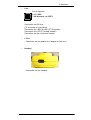
ARGUS 3u plus /3u NT
1
ARGUS
by intec Gesellschaft für Informationstechnik mbH
D-58507 Lüdenscheid, Germany, 2007
Alle Rechte, auch der Übersetzung, vorbehalten. Kein Teil
des Werkes darf in irgendeiner Form (Druck, Fotokopie,
Mikrofilm oder einem anderen Verfahren) ohne schriftliche
Genehmigung reproduziert, vervielfältigt oder verbreitet werden.
All rights are reserved. No one is permitted to reproduce or
duplicate, in any form, the whole or part of this document
without intec´s permission.
Version: 1.0
2
ARGUS 3u plus /3u NT
ARGUS
1
Introduction ......................................................... 5
2
Safety Instructions ............................................. 9
3
Technical data ................................................... 10
4
Operation ........................................................... 13
5
Menu Hierarchy ................................................. 17
6
Automatic Access Test .................................... 21
7
Setting the type of access ............................... 26
7.1 Line Test ............................................................ 27
8
Select the Access Mode ................................... 31
8.1 Operation on a BRI or U-Interface access ...... 31
8.1.1 TE-Simulation mode .................................. 31
8.1.2 Permanent circuit ....................................... 32
8.1.3 BRI Passive Trace/Monitor (optional) ........ 37
8.1.4 Recorder .................................................... 39
8.1.4.1 Administration of the recorded data ........ 41
8.2 Operation on a POTS (analog) access ........... 44
8.2.1 POTS terminal ........................................... 44
8.2.2 POTS monitor ............................................ 45
9
Single Tests ...................................................... 47
9.1 Test the Supplementary Services ................... 47
9.1.1 Suppl. Services Test for 1TR6 Protocol .... 47
9.1.2 Suppl.service interrogation in DSS1 .......... 49
9.1.3 Suppl. Services Tests – Error messages .. 53
9.2 Service check .................................................... 54
9.3 Bit error test ...................................................... 58
9.3.1 Start BERT ................................................ 60
9.3.1.1 BERT - saving ........................................ 64
9.3.1.2 Display the saved BERT results ............. 65
9.3.2 BERT wait .................................................. 66
9.3.3 B-channel loop ........................................... 67
9.4 X.31 Test ............................................................ 68
9.4.1 Automatic X.31-Test .................................. 68
9.4.2 Manual X.31 Test ...................................... 70
9.5 CF Interrogation ................................................ 72
9.6 CF - Activation .................................................. 74
9.7 CF - Delete ......................................................... 75
9.8 MSN Interrogation (only on a BRI with DSS1) 76
9.9 Time measuring ............................................... 77
9.9.1 Connection setup time ............................... 78
9.9.2 Time measurement: B-channel delay ........ 79
9.9.3 Time measurement: Interchannel delay .... 81
ARGUS 3u plus /3u NT
3
ARGUS
10 Connection ....................................................... 83
10.1 Setting up an ISDN connection ....................... 83
10.2 Clearing down an ISDN connection ............... 90
10.3 Operation on a POTS (analog) access ........... 92
11 Test Manager .................................................... 94
11.1 Simultaneously Starting Several Tests .......... 95
11.2 Switching Between Tests ................................ 98
11.3 Cancel All .......................................................... 98
12 Automatic Test ................................................. 99
12.1 Automatic Start test ....................................... 101
12.2 Display Results .............................................. 104
12.3 Sending the results of a tests to a PC .......... 105
12.4 Deleting the results of a test ......................... 106
12.5 Sending the results of all tests to a PC ........ 107
13 Level Measuring ............................................ 108
13.1 Level measuring on a BRI access ................ 108
13.2 Voltage measurement on a U-interface ........ 109
13.3 Voltage measurement on a POTS access .... 111
14 L1 status ......................................................... 112
14.1 The L1 status of a BRI access ...................... 112
15 Configuration .................................................. 113
15.1 Trace/Remote ................................................. 113
15.2 Configuration: ISDN ....................................... 115
15.3 Configuration: BERT ...................................... 119
15.4 Configuration: POTS ...................................... 122
15.5 Configuration: X.31 ........................................ 125
15.6 Configuration: ARGUS .................................. 126
15.7 Saving Call Numbers ..................................... 129
15.8 Reset ............................................................... 131
16 Accu servicing ................................................ 133
16.1 Automatic recharging of the accumulators . 133
16.2 Manual accumulator servicing ..................... 134
17
Testing Features with the Keypad ................ 135
18
Appendix ......................................................... 137
A) Acronyms ................................................... 137
B) CAUSE-Messages – DSS1 Protocol .......... 140
C) CAUSE-Messages – 1TR6 Protocol .......... 142
D) ARGUS Error Messages ........................... 144
4
ARGUS 3u plus /3u NT
1 Introduction
1 Introduction
The ARGUS 3u installation tester makes installation work
and trouble shooting on BRI and POTS accesses both safe
and uncomplicated. Additionally, the ARGUS 3u also
supports U-interface accesses. With its rechargeable
batteries and internal charger, the ARGUS 3u is
exceptionally well suited for use in the field. The intuitive
menu operation combines convenient cursor keys and
softkeys with a four-line backlit display.
Besides automatic access tests, service checks and
supplementary services tests, the ARGUS 3u also supports
among others physical measurements with evaluation,
cabling tests, and bit error rate measurements
The ARGUS can be enhanced with the WINplus software
package, which enables linking the ARGUS to a PC.
WINplus can be used to load changes to the protocols or
new functions into the ARGUS at any time (software
updates free of charge at www.argus.info).
If you use the ARGUS on a BRI in an ISDN system whose
specifications deviate from the (DIN ETS 300 102) standard
(e.g. some networked PBXs), you must take these
manufacturer-specific modifications into account. In such
cases, please contact the distributor of your ISDN PBX for
assistance.
The ARGUS Functions - Overview:
Protocol Recognition and B-Channel Test for ISDN
Accesses
After you select the operation mode, the ARGUS will
automatically determine the protocol used by the access
under test and will then test the availability of the Bchannels.
Telephone connections
Can a telephone call be placed from this access to every
other number and/or can this access receive a call?
ARGUS 3u plus /3u NT
5
1 Introduction
Service Tests
Does the tested access support connections with the most
important services, such as, ISDN telephone service, Group
4 - Facsimile or datatransmission at 64 kbit/s etc.?
Additionally, 3 user-specific services can be saved in the
ARGUS and tested on the access under test.
Bit error tests (BERT)
Performs a BERT in an extended call to itself via a loopbox
or in end-to-end operation. The ARGUS will, if needed,
handle the loopbox function itself.
Supplementary Services
The ARGUS automatically tests the supplementary services
made available by the exchange.
Leased Line Tests – tests permanent circuits with BERT
and speech
POTS functionality (does not apply for the 3u basic)
Does the POTs access support call number transfer?
Monitoring a POTS access (passive listening-in)
(does not apply for the 3u basic)
Passive trace on a BRI access
Line Test (optional)
Checks the terminating resistors for the cabling of a fourwire bus.
Detects cabling problems (e.g. broken wires, short-circuits
or crossed wires).
CF Interrogation
The ARGUS will check, whether a call diversion has been
setup on the access under test. The ARGUS can setup or
clear down call diversions in the exchange.
MSN interrogation (only on a BRI access)
On a P-MP access using the DSS1 protocol, the ARGUS
will determine the MSNs of the access under test.
6
ARGUS 3u plus /3u NT
1 Introduction
Access Acceptance Reports (with optional WINplus)
When the ARGUS is linked to a PC via the serial interface, it
is, as an example, possible to create and print a
comprehensive test report on the PC.
Testing Features with the Keypad
Supports manual tests in the so-called keypad mode. If the
network supports this feature, the user can send a command
sequence and can then test service features in a dialog.
Should you have any further questions, please contact us:
intec Gesellschaft für Informationstechnik mbH
Rahmedestr. 90
D-58507 Lüdenscheid
Tel.: +49 (0) 2351 / 9070-0
Fax: +49 (0) 2351 / 9070-70
ARGUS 3u plus /3u NT
7
1 Introduction
8
ARGUS 3u plus /3u NT
2 Safety Instructions
2 Safety Instructions
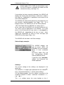
The ARGUS may only be used with the included
accessories. Usage of other accessories may lead to
erroneous measurements and may even cause damage to
the ARGUS and the connected installation.
The ARGUS is only to be used in accordance with the
instructions in this documentation. Any other usage may
result in bodily injury and destruction of the ARGUS.
•
To prevent electrical shocks or damage to the ARGUS,
do not connect it to lines with voltages in excess of
100V!
•
Never attempt a measurement with the case open!
•
The ARGUS is not watertight. Protect the ARGUS from
exposure to water!
•
Do not use batteries in the ARGUS3u; this tester is
designed to be used with - and to automatically charge accumulators (rechargeable batteries).
(see page 133 Accu servicing)
ARGUS 3u plus /3u NT
9
3 Technical data
3 Technical data
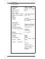
Dimensions /
Weight
Height 229 mm
Inputs / Outputs
1 RJ45 for BRI, UInterface
or
POTS
access
Width 72 mm
Depth 35 mm
Weight 350 g (without
batteries and protective
case)
1 jack for an external
power supply
Keypad
1 RJ45 for
Line Test (optional) and
serial transfer
21 Keys
LCD display
LCD display with
Temperature Ranges
switchable
Ambient-temperature:
background lighting
0 °C to +50 °C
4 lines with 16 characters
Operating
temperature:
-5 °C to +55 °C
Memory
EEPROM Non-volatile
memory:
16 kBytes
Power
Flash program
memory:
S-RAM:
2 Mbyte
512 Kbytes
Supply
9 V, plug-in
supply
power
or
BRI feed
ARGUS 3u only:
3 Accumulators AA
(Mignons) NiMH
1600mAh
10
ARGUS 3u plus /3u NT
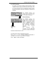
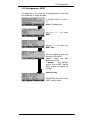
4 Operation
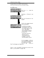
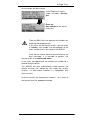
4 Operation
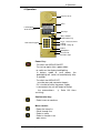
Receiver inset
LEDs
LCD display
4x16 characters
Soft keys
Menu control
Confirmation key
Numerical keypad
Layer 1 measurement
Calling
Pickup / Hang up
Power
Microphone
Fastener for
shoulder strap
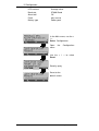
Power Key:
- To switch the ARGUS ON/OFF
- To start up again after a power down
- to switch on the display backlighting
In battery mode to save power, the
backlighting will switch off automatically after
5 seconds.
- To switch the ARGUS OFF
(must be pressed somewhat longer)
If it is turned off while the power supply
is connected, the unit will begin to charge
the accumulators.
(s. Seite 133 Accu
servicing)
Confirmation key:
- Select menu or continue
Menu control:
- Open the menu list
- Scroll through lists
- Select a menu
- Select a function in an
open menu
ARGUS 3u plus /3u NT
13
4 Operation
Telephony
- Pickup or hang up
- Simplified overlap signalling: Press
the telephone key twice.
Layer 1 Measurement:
start the Layer 1 measurement
(Level/Voltage)
Number Pad:
- Entry of the digits 0....9 and of the
special characters *, # (e.g. the call number or
numerical entry in a function)
- Direct function call
(see Seite 25)
Softkeys:
The function of the 3 softkeys varies with the
situation.
The current function of each softkey is shown in
the highlighted fourth line of the display.
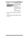
Connectors on the end:
•
9 VConnection for the external power supply. When the
power supply is plugged into this connector, the
rechargeable batteries will be disconnected.
After it is switched off, the ARGUS will automatically
recharge the accumulators(s. Seite 133 Accu servicing).
14
ARGUS 3u plus /3u NT
4 Operation
•
Line
Pin Assignment
3/4/5/6 BRI
7/8U-interface and POTS
Connection for BRI lines
(TE simulation or monitoring)
Connection for a BRI terminal (NT-Simulation)
Connection for a POTS (analog network)
Connection for the U-interface network
•
L-Test
- Connection for the optional test adapter for line tests
•
Headset
- Connection for the Headset
ARGUS 3u plus /3u NT
15
4 Operation
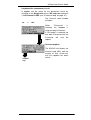
Replacing the accumulators
The battery compartment for the three accumulators
(rechargeable batteries) is located on the back of the case.
Unscrew the screws to remove the cover of the case and
insert the accumulators in accordance with the polarity
marking.
Use only NiMH accumulators.
The current state of the charge will (if the ARGUS is not
connected to a power supply) be displayed graphically.
In the LCD display, a battery symbol will begin to blink, when
there is still approximately 5 minutes reserve. During this
period, it is possible that there may be audible interference
and in rare cases even malfunctions (Seite 133).
Power Down
In accu/battery operation, if the ARGUS is idle for 15
minutes, it will automatically switch to the power-down mode
(power-down). The ARGUS will remain in power-down
mode until the Power-Key is pressed again.
Reasonably enough, the ARGUS will not enter power-down
mode during a test (e.g. Loopbox) or when it is in Trace
mode.
As an alternative, it is possible to operate the ARGUS using
the included power supply. When the power supply is
connected,
the
accumulators
are
automatically
disconnected.
The ARGUS can also be powered from the BRI line. In this
case, it does not need accumulators or the plug-in power
supply.
Whenever the ARGUS is powered from the plug-in power
supply or the BRI line, the power-down mode is reasonably
enough not active.
16
ARGUS 3u plus /3u NT
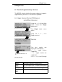
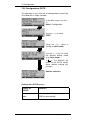
5 Menu Hierarchy
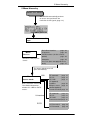
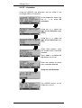
5 Menu Hierarchy
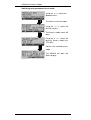
Switch the ARGUS
The ARGUS automatically performs
an access test and checks the
2-wire line for HF signals (page 21).
A list of all the menus will
open
Basic Rate Interface
page 26
U-Interface
page 26
POTS interface ( for the 3u basic
optinal)
page 26
Automatic
page 26
Line Test (does not apply for the 3u
basic)
page 27
Menu
Access
Selection of the physical
access
The Access Mode menu will
open automatically
BRI
Menu
Access mode
BRI, U-Interface and POTS
The ARGUS determines
whether it is a BRI or POTS
access.
U-interface
POTS
ARGUS 3u plus/3u NT
TE automatic
TE P-P
TE P-MP
NT (optional)
Recorder
BRI pass. trace
Monitor (optional)
Permanent circuit
page 31
page 31
page 31
page 39
page 37
page 32
TE automatic
page 31
TE P-P
page 31
TE P-MP
page 31
Permanent circuit page 32
POTS terminal
POTS monitor
page 44
page 45
17
5 Menu Hierarchy
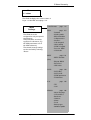
Menu
Single
BRI, U Interface
Bit Error Test page 58
Supplementary
Services
page 47
Service Testspage 54
X.31 Test
BERT Start
BERT Wait
B-channel
page 68
CF Interrogation
page 72
Automatically
Manually
CF Activation page 74
CF - Delete page 75
MSN Interrogation
page 76
POTS
Telephony
Connection
setup time
B-channel
delay
page 92
BRI, U Interface
Start new one
End all
Menu
Test Manager
page 95
page 98
Management of multiple,
simultaneous and independent
tests/connections
BRI, U Interface
Menu
Automatic Tests
The ARGUS will automatically
execute the
test sequence and save the results
in its internal Flash
Start
View
Test data to PC
Delete
All tests to PC
page
page
page
page
page
101
104
105
106
107
BRI
Menu
Level Measuring
Remote end page 108
U-interface
Uk0 feed
Power U
page 109
page 109
POTS
Polarity
18
page 111
ARGUS 3u
5 Menu Hierarchy
Menu
L1 status
The ARGUS displays the current status of
Layer 1 on the BRI accesspage 112.
Menu
Settings
Trace/Remote
page 113
ISDN
page 115
- Protocol
- Alerting mode
- BRI termination
- Call parameter
- Services
- Call accepted
- Voice coding
- DTMF / Keypad
- Dest. no. MSN
- CUG Index
BERT
page 119
- BERT duration
The ARGUS can be
configured to suit your special
requirements.
The parameters are clearly
organised in submenus (e.g.
the ISDN parameters are in
the ISDN submenu)
The default (factory) settings
can be restored by selecting
"Reset“.
(time)
- Bit patt. BRI/U
- Error level
- HRX value
POTS
page 122
- POTS dial
- POTS CLIP
- DTMF parameter
- FLASH time
X.31
page 125
- TEI
- LCN
ARGUS
ARGUS 3u plus/3u NT
page 126
- Menu language
- LCD contrast
- Baud rate
- Handset
- Alarm
- Feed
- Battery type
- Software option
19
5 Menu Hierarchy
Menu
Accu servicing
20
Numbers
page 129
Reset
page 131
Charging
page 133
Discharging page 133
ARGUS 3u
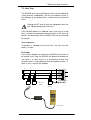
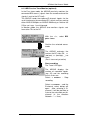
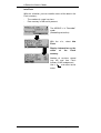
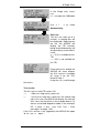
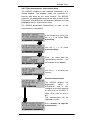
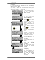
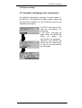
6 Automatic Access Test
6 Automatic Access Test
Using the included cable, connect the ARGUS to the access
to be tested.
Power Key: Switch on the ARGUS.
The ARGUS automatically
performs an access test
(Automatic setting in the
Access menu see Page 26).
No manual entries are
required. The
The access under test (BRI,
U interface or POTS) can
also
be
connected
afterwards.
If the ARGUS finds a DC
voltage on the 2-wire line (UInterface or POTs), it will
check whether there is a HF
signal on the line.
With < TE >: determine the
access
If the test fails or if you wish to provoke a specific error
situation, you can manually select any interface in the
Access menu later (see “Setting the type of access” on page
26).
Initializing the ARGUS :
- Operating the ARGUS on a BRI or U-Interface access:
The ARGUS will first setup Layer 1. While Layer 1 is being
setup, LED L1 over the display will blink. If the ARGUS
cannot setup Layer 1, it will display the message "No Net“.
When the ARGUS is operated on a U-interface access, it
can take up to 2.5 minutes to activate Layer 1.
As soon as Layer 1 is successfully setup, LED L1 will light
continuously.
Once Layer 2 has been setup LED L2 will light.
ARGUS 3u plus/3u NT
21
6 Automatic Access Test
If both modes (P-P / P-MP) are found when Layer
2 on the D-channel is checked, the mode must be
selected manually (see Page 31).
If everything has been correctly detected, the ARGUS will
display the successfully found access and access mode in
the third line. Additionally, a qualitative assessment of the
level will be displayed.
The ARGUS will automatically determine the protocol or use
the manually selected protocol (see Page 116) . On a
bilingual access, the ARGUS will use the DSS1 protocol.
LED L3 will light after the ARGUS has setup Layer 3.
At the same time the ARGUS will start the B-channel test.
The results will be displayed on the ARGUS. If an error
occurs in the B-channel test (e.g. access is not plugged-in),
the ARGUS will - depending on the class of error - either
repeat the initialization or show an error message (see
ARGUS Error Messages Page 144).
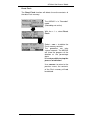
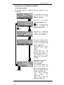
The ARGUS will then idle in the Status display.
Status display example:
The ARGUS displays the
type of access (BRI), the
availability of the B-channels
(B12), a level evaluation
(OK),
the access mode (TEs), the
bus configuration (P-MP)
and the protocol (DSS1).
If you press the <RESTART>
softkey, the B-channel test
will be repeated.
Softkeys:
The current settings of the softkeys are displayed in the
fourth line.
The ARGUS is in largest part operated with the two ↓ ↑ Keys, the confirmation key ✓ and the three softkeys.
On the following pages, only the softkey's meaning in the
respective context is shown - enclosed in brackets < > ,
e.g. < NO >.
The < ✓ > softkey serves the same function as the ✓
22
ARGUS 3u plus/3u NT
6 Automatic Access Test
confirmation key and the < ↓ > softkey performs the same
function as the corresponding arrow key on the ARGUS
keypad.
In the example above, the test found that it is a BRI multiple
device access using the DSS1 protocol
Shown on the second line in the display:
The availability of the B-channels:
B12
both channels are available
B1only B-channel 1 is available
B-2only B-channel 2 is available
B-no B-channel available
If only one B-channel is available, this can have an
impact on the service check and the testing of the
supplementary services.
Level evaluation only on a BRI access:
OK
the level is in order
<<
the level is too low
>>
the level is too high
--
no level
Shown on the third line in the display:
Access Mode:
TEs = TE Simulation Slave Mode
TEm = TE Simulation Master Mode
Bus configuration:
P-P:
Point-to-Point
P-MP: Point-to-Multipoint
It must be mentioned again, that the ARGUS only
determines the general bus status once when switched on
or when the ARGUS first connected.
On the other hand, the status of the protocol stacks for Layer
1, 2 and 3 will be continually monitored and displayed.
ARGUS 3u plus/3u NT
23
6 Automatic Access Test
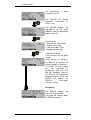
- Operating the ARGUS on a POTS access (for ARGUS
3u basic optional)
The ARGUS displays the
access type (POTS) and the
line voltage when idle.
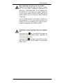
ARGUS - Main menu
Status display
Repeat
Bchannel test
Main Menu
Marked
Menu
List
is
continued
Return to
Status display
scroll
further
.
The ARGUS opens
the menu marked with
a →.
In the Main menu, you can scroll through the available
menus with the <↓ > key:
BRI
Access
U-interface
Access
POTS
Access
Single Tests
Single Tests
Single Tests
Test Manager
Test Manager
_______
Automat.Tests Automat.Tests Automat.Tests
Level
Level
Level
Measuring
Measuring
Measuring
L1 Status
________
_______
Configuration
Configuration
Configuration
Access
Access
Access
24
ARGUS 3u plus/3u NT
6 Automatic Access Test
Accu servicing Accu servicing Accu servicing
With the <✔>, you can open the menu currently marked with
the → (in the example Single Tests).
Name of the
opened menu
List
is
continued
Return to
previously shown
Display
scroll
further
The ARGUS opens
the type of function/
submenu marked with
→.
Using the numeric keys to start a function:
Using the numeric keys, you can start important ARGUS
functions directly, regardless of the currently active menu
level:
Numeric key
Numeric key
Numeric key
Numeric key
Numeric key
Numeric key
Numeric key
2Start Service Test
3 Start Supplemental Service Test
4 Start Auto. Test
6 Start Test Manager
7Open Speed-Dialing Memory
8Trace ON/OFF
9 Start Bit Error Rate Test (BERT)
If a function is called where the ARGUS expects the
entry of a digit, pressing a number key will be
interpreted as the expected input.
ARGUS 3u plus/3u NT
25
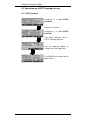
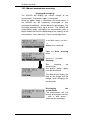
7 Setting the type of access
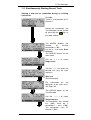
7 Setting the type of access
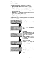
In the Access menu, the user must select the type of
physical access to which the ARGUS is actually connected.
If Automatic is selected, a fully-automatic sequence will be
started: The ARGUS will automatically determine the type of
interface (BRI, U interface or POTS) and set the access to
TE-mode.
Status display
If you press the <RESTART>
softkey, the B-channel test
will be repeated.
Open the Main menu
Using the < ↓ > select the
Access menu
The Access menu will open
Using the <↓> select the type
of access
(e.g. BRI access)
Confirm the access
The Access Mode menu will
open automatically.
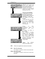
The following applies for all
displays: If you press the <
to the previous display.
26
> , the ARGUS will return
ARGUS 3u plus/3u NT
7 Setting the type of access
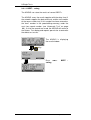
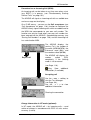
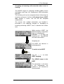
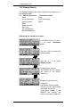
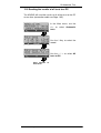
7.1 Line Test
The ARGUS tests the terminating resistors for the cabling of
a four-wire bus. Additionally, the test also detects errors in
the cabling e.g. any broken wires, short-circuits and crossed
wires.
Unplug the NT and all terminal equipment from the
bus, before performing a line test!
If the ARGUS detects an operator error (Line test on a fed
bus), it will emit a continuous acoustic signal. In this case, to
prevent the destruction of the ARGUS, the line test will not
be started.
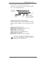
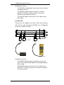
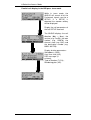
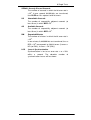
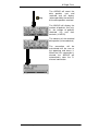
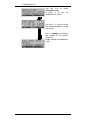
Test sequence:
To perform a thorough test of the lines, the test must be
done in 2 steps.
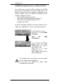
First step:
Use the test adapter to connect the ARGUS to the lines to
be tested. In this step, the ARGUS will determine whether or
not there is a short circuit or a terminating resistor and
whether there is a fault between the terminating resistor – if
there is one – and the test adapter.
3
6
4
NT
5
U Interface
Unplug the NT!
Socket 1
BRI
Last
socket
L-Test jack
ARGUS 3u plus/3u NT
27
7 Setting the type of access
Possible test results:
-
The ARGUS has detected a short-circuit: Clear the fault
and repeat the test
-
The ARGUS reports that the resistance is wrong:
Repeat the test from another socket, if necessary
remove the terminating resistor(s)
-
The ARGUS reports that the line is OK: Continue test
with step 2
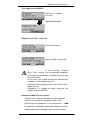
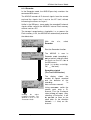
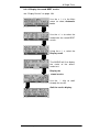
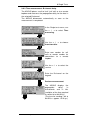
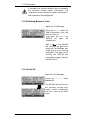
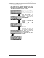
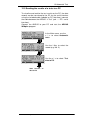
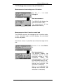
Second step:
Connect the test adapter to the jack, which was tested as
OK in the first step. Connect the ARGUS via its L-Test jack
to the next socket on the bus.
3
6
4
NT
5
U Interface
Unplug the NT!
Socket
BRI
Last
socket
L-Test jack
Possible test results:
-
The ARGUS reports broken connections or crossed
wires: Clear the fault and repeat the test beginning with
the first step.
-
The ARGUS reports that the line is OK: Connect the
ARGUS (L-Test jack) to each of the sockets on the bus
one after the other.
28
ARGUS 3u plus/3u NT
7 Setting the type of access
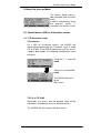
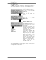
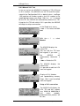
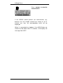
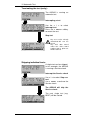
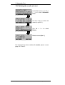
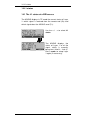
Test steps on the ARGUS:
With the <↓>, select
Line Test.
Start the Line Test
Sample test results – Line Test:
No errors occurred.
Wires 3 and 6 are crossed.
If the message “Crossed
wires: Term. wrong”, the measurement conditions
with respect to the location or complexity of the fault
are unfavorable.
In this case, you should change the measurement
conditions in the following manner:
Remove the terminating resistors from the bus and
repeat the test.
Frequently it is enough to simply swap the test
adapter and the ARGUS.
Comments about the test results:
-
The bus can first be considered to be free of defects,
when all of the sockets have been tested as OK.
-
Short-circuits are reported as a resistance value < 10 Ω.
-
Crossed wires and broken connections between the test
adapter and the terminating resistor cannot be found.
ARGUS 3u plus/3u NT
29
7 Setting the type of access
-
30
The displayed test results are either for just the bus lines
between the ARGUS and the test adapter in the case of
cross-wires and broken connections or for the entire bus
in the event of short-circuits and terminations.
ARGUS 3u plus/3u NT
8 Select the Access Mode
8 Select the Access Mode
The Access Mode menu is
not selectable from the Main
menu.
It opens automatically once
the physical access is
selected in the Access menu.
8.1 Operation on a BRI or U-Interface access
8.1.1 TE-Simulation mode
TE automatic
On a BRI or U-interface access, the ARGUS will
automatically determined the D-channel Layer 2 mode
(PP or P-MP). If the ARGUS determines that the access
supports both modes, the following Configuration menu
will open:
Using the <↓ >, select L2
mode
.
Confirm the selected L2
mode
The ARGUS will return
to the
Main menu.
TE P-P or TE P-MP
Afterwards, the access and the protocol stack will be
initialized in accordance with the selected setting.
The ARGUS will then jump to the Main menu.
ARGUS 3u plus/3u NT
31
8 Select the Access Mode
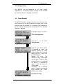
8.1.2 Permanent circuit
With the <↓ >, select
Permanent switch.
Access mode confirmed
The ARGUS is now switched
to Permanent circuit mode
(the display shows LL
[Leased Line]) and will open
the Status display.
Besides dial-up connections
to any subscriber, ISDN also supports the use of permanent
circuits switched to a specific remote location.
These permanent circuits are available after setting up
Layer 1, in other words after synchronizing both terminals by
exchanging HDLC-frames.
As a quick test of a permanent circuit, you can simply call
the opposite end using a selected B-channel.
However, for a more revealing test of a permanent circuit,
you should perform a bit error rate test.
Both ends of the permanent circuit must use the same
channel.
32
ARGUS 3u plus/3u NT
8 Select the Access Mode
Telephony on permanent circuits
The function can be started with the
-Key or via the
Phone / connec. function in the Single tests menu (see
Chap. 10 page 83).
After the B-channel for the permanent circuit is selected, the
telephone connection will be setup automatically.
The ARGUS displays the Bchannel used (e.g. B01) and
the duration of the permanent
circuit.
Use the< TM > softkey to start
the Test Manager (see Page
94)
Terminate permanent circuit
The ARGUS will open the
Status display
.
BERT on permanent circuits
A number of variations are possible in testing the permanent
circuit with the bit error rate test.
In the simplest case, a B-channel loop will be set up at the
remote end.
Start the BERT from the Single tests menu / Bit error test
submenu / BERT start(see “Start BERT” on page 60 ).
After selection of the channel to be tested (B-channel or Dchannel), the ARGUS will send the test pattern, receive it
back and evaluate it accordingly.
The displays and operation are, in largest part, similar to
those of a BERT on a dial-up connection (see page 58 Bit
error test), you simply need not enter call numbers or select
a service.
In the case of a BRI access in end-to-end mode (see “Bit
error test” on page 58 and on page 66 “BERT wait”), it is
ARGUS 3u plus/3u NT
33
8 Select the Access Mode
also possible to run a BERT in the D-channel.
In this case, the channel select window will open:
On a BRI access:
With the < ↓ > , select the
channel
Selecting a B-channel (e.g
64k)
Enter the B-channel on the
keypad.
.
Confirm the selected channel
and start the BERT.
The ARGUS will display
- the bit pattern (e.g. 2^15)
- the channel / bit rate used
(e.g. B02/1984k)
- the remaining test time in
Hours: Minutes: Seconds
(e.g. 00:24:12)
- the bit errors that have
occurred (e.g. 2)
- Synchronicity of the
bit pattern (synchron)
- the LOS-counter (e.g. 0)
.
Use the <ERROR > softkey to
insert artificial bit errors to test
the reliability of the BERT.
Use the <TM > softkey to
Start Test Manager (see Page 94).
Once it is over, the ARGUS will display the results of the
BERT ( see “Start BERT” on page 60 ).
34
ARGUS 3u plus/3u NT
8 Select the Access Mode
Loopbox with a permanent circuit
A loopbox can be setup for the permanent circuit by
selecting in the Single tests menu / Bit error test submenu
/ the B-channel LOOP (see “B-channel loop” on page 67).
The Channel select window
will open.
On
a
BRI
When
"B-channel"
is
selected, the Loopbox is
setup for both B-channels.
If "All framed" is selected, not
only both B-channels but the
D-channel will also be
looped.
Activate loopbox
Loopbox
stop
ARGUS 3u plus/3u NT
The ARGUS will display the
channel used (B01) and the
amount of time (h:min:sec)
that the Loopbox has been
active.
35
8 Select the Access Mode
Switching from permanent circuit mode
Using the < ↓ >, select the
Access menu.
The Access menu will open
Using the < ↓ >, select the
desired access.
The Access mode menu will
open.
Using the < ↓ > , select the
desired Access mode (e.g.
TE P-MP).
Confirm the selected access
mode
The ARGUS will open the
Status display
36
ARGUS 3u plus/3u NT
8 Select the Access Mode
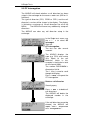
8.1.3 BRI Passive Trace/Monitor (optional)
In the Pass.trace mode, the ARGUS passively monitors the
connected BRI access (signals from the remote end and the
signals it sent to the NT itself) .
The ARGUS sends the captured D-channel signals via the
serial interface to the connected PC, which must be running
either ARGUS WINplus or ARGUS WINAnalyse. Neither the
S-Bus nor Layer 1 are influenced.
In Monitor mode, the ARGUS also monitors signals sent
from other TEs to the NT.
With the <↓>, select BRI
pass. trace.
Confirm the selected access
mode
The ARGUS evaluates the
level on the NT-side: OK, <<
(too low), >> (too high), _ (no
level)
(Pass. trace not yet active)
Start recording
The Trace LED lights.
The ARGUS displays the
number of recorded signals
(e.g. 25) and the recording
time in h:min:sec.
Select < ABORT> : Stop
recording.
Select < LISTEN > : and the
B-channel select dialog will
open. After selecting a Bchannel, it will be possible to
listen to the voice data on this
channel (in the direction
Network -----> User).
ARGUS 3u plus/3u NT
37
8 Select the Access Mode
Parallel call display in the BRI pass. trace mode
While in trace mode, the
ARGUS will search all of the
D-channels signals sent for a
SETUP. If a SETUP is
detected, the <CALL> softkey
will be displayed.
Display the call parameters of
the last SETUP received.
The ARGUS displays the call
direction (Net -> User), the
service (e.g. FaxG3), the own
number (e.g. 125670), the
channel used (e.g. B01) and
the destination number (e.g.
02351 901729).
Display of other parameters:
Sub-address (SUB),
User-User-Info (UUI),
DSP messages (if
existent),
Type of Number (T.O.N) ,
Numbering plan (NP).
38
ARGUS 3u plus/3u NT
8 Select the Access Mode
8.1.4 Recorder
In the Recorder mode, the ARGUS passively monitors the
connected BRI access.
The ARGUS records all D-channel signals from the remote
end and the signals that it sent to the NT itself, without
influencing the access or Layer 1.
Unlike in the BRI pass. trace mode, the recorded D-channel
signals will be saved in the ARGUS’s internal Flash memory
and not sent to a PC.
The storage is organized as a ring buffer, i.e. as soon as the
Flash memory is full, the ARGUS will automatically overwrite
the oldest data.
With
the
Recorder
<↓>,
select
Start the Recorder function.
The ARGUS is now in
Recorder mode (recording is
not yet active!) and will check
the levels on the NT side of
the BRI access.
Level ( << to low, >> to high,
OK, __ No level).
Recording started
(The Trace LED flashes)
Quitting
the
active
recording function. The
ARGUS is then in the
“Recorder” mode.
ARGUS 3u plus/3u NT
The display shows the
number of signals received
and the duration of the
recording
in
hours:mínutes:seconds.
Using <LISTEN>, switch the
speech path onto a Bchannel. First the B-channel
select dialog will open. After
selecting a B-channel, it will
be possible to listen to the
voice data (in the direction
Network ----> User) on this
channel.
39
8 Select the Access Mode
Parallel call display while recording
The ARGUS searches all of the D-channel signals sent for a
SETUP. If a SETUP is detected, the <CALL> softkey will be
displayed.
Use <CALL> to display the call parameters of the last
SETUP received (see page 39).
40
ARGUS 3u plus/3u NT
8 Select the Access Mode
8.1.4.1 Administration of the recorded data
In the Recorder mode, several functions are available for
administration of the data saved in the Flash memory:
- PC load all
- Info Flash
- Reset Flash
PC load all
With the PC load all function, the ARGUS will download all
of the contents of the Flash memory via the serial interface
to the PC, which must be running either WINplus or
WINanalyse.
The ARGUS is in "Recorder"
mode
(Recording not active)
Using < ↓ >, select PC load
all.
Start
charging
accumulators
the
Select < ABORT >to stop the
transfer.
After the data has been
successfully transferred to the
PC, the Flash memory
contents can be deleted.
Select < YES > to delete the
Flash memory contents.
Select < ABORT> to quit and
not delete the Flash memory
contents.
ARGUS 3u plus/3u NT
41
8 Select the Access Mode
Info Flash
With this selection, you can read the status of the data in the
Flash memory:
- The number of saved sessions
- Free memory in MB and in percent
The ARGUS is in "Recorder"
mode
(Recording not active)
With the <↓>, select Info
Flash.
Display information on the
status
of
the
Flash
memory.
Number of sessions stored
(e.g 45) and free Flash
memory in MB and percent.
Use <
menu.
42
> to return to the
ARGUS 3u plus/3u NT
8 Select the Access Mode
Reset Flash
The Reset Flash function will delete the entire contents of
the data Flash memory.
The ARGUS is in "Recorder"
mode
(Recording not active)
With the < ↓ >, select Reset
Flash.
Select < YES > to delete the
Flash memory contents.
The procedure can take
several seconds. The ARGUS
will show the progress of the
detetion as the percentage
done.
It is not possible to stop the
process of deletion!
Use <ABORT> to return to the
previous menu; the contents
of the Flash memory will not
be deleted.
ARGUS 3u plus/3u NT
43
8 Select the Access Mode
8.1 Operation on a POTS (analog) access
8.1.1 POTS terminal
Using the < ↓ >, select POTS
interface.
Confirm the access
Using the < ↓ >, select POTS
terminal.
The Argus behaves like a
POTS (analog) terminal.
Use the <CALL> softkey to
setup a call (see Page 92).
The ARGUS will return to the
Main menu.
44
ARGUS 3u plus/3u NT
8 Select the Access Mode
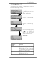
8.1.2 POTS monitor
Essentially, the POTS (analog) monitor provides a high
impedance tap that does not influence the interface. You
can listen to the line with the integrated handset without
having the ARGUS send on or otherwise influence the
interface.
The ARGUS displays the
voltage level on the line when
it is "on hook“ (not busy).
Start monitoring
The ARGUS displays the
voltage (when "off hook"), the
number of the caller (when
CLIP is supported) and the
DTMF characters dialed by
both telephone subscribers
and the SMSs received
(optional).
Monitoring
Any
received
DTMFstop
characters will be appended
to the line, which will shift left
for each character once it is full.
An incoming call will be signalled acoustically.
Press the < ↓ > -Key to display additional information, if
available on the access (e.g. advice of charges).
Press < DEL > to clear the display.
ARGUS 3u plus/3u NT
45
8 Select the Access Mode
46
ARGUS 3u plus/3u NT
9 Single Tests
9 Single Tests
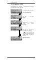
9.1 Test the Supplementary Services
The ARGUS checks whether the access under test supports
supplementary services in 1TR6 or DSS1 protocol.
9.1.1 Suppl. Services Test for 1TR6 Protocol
(only BRI or U-Interface)
Using the < ↓ > in the Main
menu, select the Single
tests menu.
The Single
opens
tests
menu
Using the < ↓ >, select
Supp.serv.test.
Start test
The ARGUS will return to
the
The
test
results
are
displayed automatically:
+
=
suppl. service
supported
=
suppl. service not
supported
Use < ↓ > to scroll through
the test results
Sperre
Blocking enabled for outgoing calls
AWS1
Call forwarding type 1 enabled (continuous)
AWS2
Call forwarding type 2 enabled (case by case)
Anschluss
GBG
Access belongs to a Closed Users Group
ARGUS 3u plus/3u NT
47
9 Single Tests
Geb.anzeige
Advice of charge
Rufnummern- Setup call number identifier
Id
- against malicious calls
48
ARGUS 3u plus/3u NT
9 Single Tests
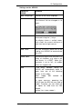
9.1.2 Suppl.service interrogation in DSS1
In the Single tests menu,
using the < ↓ >, select
Supp.serv.test.
Use the keypad to enter the
"Own number" or select if
from
the
speed-dialing
memory (the number of the
access under test) (see
“Saving Call Numbers” on
page 129.). The ARGUS will
test the availability of the
supplementary service (in
part by placing a call to
itself).
Using the < ↓ > , select the
service which should be
used for the supplementary
services test.
Confirm the service.
Enter the B-channel on the
keypad. By default, the
channel last used will be
suggested. If you enter an *,
the ARGUS will choose any
B-channel that is free.
Confirm the B-channel
Use the < ↓ > to select the
supplementary service (e.g.
TP) that you want the
ARGUS to check whether it
is supported on the access
under test.
Start test
The ARGUS will display the
results of the test once it is
done:
+ = suppl. service supported
- = suppl. service not supported
Use the < ↓ > to scroll through the test results.
If you press the <
ARGUS 3u plus/3u NT
> , the ARGUS will return to the
49
9 Single Tests
previous display (this applies for all displays).
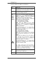
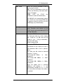
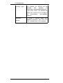
Test
Comments
TP
The ARGUS tests the TP (Terminal Portability)
supplementary service by making a self call.
HOLD
The ARGUS tests the HOLD supplementary
service by making a self call.
CLIP
In this test, the ARGUS checks whether the 4
supplementary services CLIP,CLIR, COLP and
COLR are supported. To do so, the ARGUS
will setup as many as three calls to itself.
CLIP: Will the calling subscriber's number be
displayed at the called subscriber?
(t = CLIP temporarily available
p = CLIP permanently available)
CLIR: Will the display of the calling
subscriber's number at the called subscriber be
suppressed or is it possible to temporarily
suppress the display?
If the ARGUS displays an *, it is not possible to
determine the availability of the service, since
no CLIP has been setup.
(t = CLIR temporarily available
p = CLIR permanently available)
COLP: Will the call number of the subscriber
who answered be displayed on the caller's
phone?
COLR: Will the display of the call number of
the subscriber who answered be suppressed
on the caller's phone or is it possible to
temporarily suppress the display?
(CLIP,
CLIR,
COLP,
COLR )
If the ARGUS displays an *, it is not possible to
determine the availability of the service, since
no COLP has been setup.
The suppl. services pairs CLIP and CLIR as
well as COLP and COLR will be tested. If CLIR
or COLR is setup permanently, it is not
possible to make a clear assessment.
DDI
Can a caller directly dial in to an extension on
the PBX access under test?
MSN
Is the supplemental service MSN available?
50
ARGUS 3u plus/3u NT
9 Single Tests
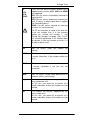
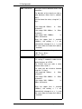
CF
(CFU,
CFB,
CFNR)
In this test, the ARGUS checks whether the 3
supplementary services CFU, CFB and CFNR
are supported.
CFU: Can this access immediately forward an
incoming call?
CFB: Can this access forward an incoming call
when it is busy; in other words does it support
Call Forwarding Busy?
CFNR: Can this access forward an incoming
call when it is not answered?
The CF test attempts to setup a call diversion
to the call number that is in the memory
location for “remote call number 1” (see
“Saving Call Numbers” on page 129). The CF
test cannot be performed, if this location does
not contain a valid call number to which it is
possible to divert a call.
CW
Does the access under test support call
waiting?
CCBS
Will the access under test automatically recall
a remote subscriber, if the number called was
busy?
CCNR
Will the access under test automatically recall
a remote subscriber if the call was not
answered?
MCID
Does the access tested allow identification of
malicious callers (call tracing)?
3pty
Does the access under test support a threeparty conference call?
For this test, you need the assistance of a
remote subscriber, whose call number must be
entered.
ECT
Is an explicit call transfer supported by the
access under test?
For this test, you need the assistance of a
remote subscriber, whose call number must be
entered.
ARGUS 3u plus/3u NT
51
9 Single Tests
AOC
The ARGUS checks whether the charges can
be sent to the access under test. The test uses
a call to oneself to check both AOC-D (AOC
during a call) and AOC-E (AOC at the end of a
call).
SUB
A call is made to oneself and answered to
check the transfer of the sub-address in both
directions.
Are sub-addresses supported on the access
under test?
UUS
Does the access under test support the
transfer of user data?
CUG
The ARGUS then uses a self call to check
whether the access under test belongs to a
closed user group.
52
ARGUS 3u plus/3u NT
9 Single Tests
9.1.3 Suppl. Services Tests – Error messages
If an error occurs during the
Supplementary
Services
Tests or if it is not possible to
setup a call, the ARGUS will
display the corresponding
error code (e.g. 28).
Use < ↓ > to scroll through.
In the example, the error belongs to the error class "wrong
or invalid number".
In the table below, you will find that this is an error from the
network and that it reports that the call number was
incomplete or in the wrong call number format (see
“CAUSE-Messages – DSS1 Protocol” on page 140.).
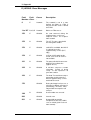
Distributing the error codes into error classes:
Error
class
Description
Cause
(from Cause
network)
ARGUS
1 TR6
DSS1
internal
A
No or
access
B
Wrong or invalid 53, 56
number
C
One or more
B-channels busy
10,33,59 17,34,47
___
D
Wrong service
3
___
another
__
__
201,204,205,
210,220
1,2,3,18,21
22,28,88
152,161,162,
199
49,57,58,63
65,70,79
For further information regarding error codes:“ARGUS Error
Messages” on page 144, “CAUSE-Messages – DSS1
Protocol” on page 140 and “CAUSE-Messages – 1TR6
Protocol” on page 142.
ARGUS 3u plus/3u NT
53
9 Single Tests
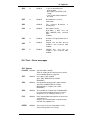
9.2 Service check
The ARGUS checks, which of the following services are
supported by the access under test:
Service
Name in the
ARGUS
display
abbreviation
Language
Language / Lang
Unrestricted Digital
Information
UDI 64kBit / UDI 64
3.1 kHz Audio
Tel.analog / Tel.
7 kHz Audio
7 kHz audio / 7 kHz
Unrestricted Digital
Information with tones /
Display
UDI+TA / UDI TA
Telephony
Tel.ISDN / Tel.
Facsimile Group 2/3
Fax G3 / FaxG3
Facsimile Group 4 Class 1
Fax G4 / FaxG4
Teletex service basis and
mixed mode and facsimile
service Group 4 Classes II
and III
Mixed Mode / Mixed
Teletex
mode
Teletex / Ttx64
Service
basis
International inter working
for Videotex
Videotex
Telex
Telex
OSI application according
to X.200
OSI
7 kHz Telephony
Tel.7kHz / Tel7k
Video Telephony,
first connection
Videotel.1 / Vid.1
Video Telephony,
second connection
Videotel.2 / Vid.2
Three user-specific
Services
(see “Services” on page
117.)
Userspec.1 /
Userspec.2 /
Userspec.3 /
The test runs automatically.
For each service, the ARGUS will place a call to itself (to the
access under test). However, the call will not be answered
54
ARGUS 3u plus/3u NT
/
9 Single Tests
so no charges will be incurred.
In the Single tests menu,
< use ↓ to select > Service
test.
Enter the
Own number of the access
under test
There are PBXs that use separate call numbers for
incoming and outgoing calls.
In this case, for the Service checks, you can enter
a “remote” call number that corresponds to the
“own” number that is not stored in the ARGUS.
If the Service check should extend outside of the
local exchange, it is possible to perform the
Service check in an end-to-end mode.
In this case, you must enter the remote call number for a
second terminal device.
The ARGUS will then automatically check whether the
remote terminal can accept the call under the various
services – in other words, whether it is “compatible” with
these services.
In the test results, the second part (second +, - or *) refers to
the answer from the remote exchange.
ARGUS 3u plus/3u NT
55
9 Single Tests
The ARGUS will display the
results of the test once it is
done.
Use the < ↓ > to scroll
through the test results.
The ARGUS makes a
distinction between outgoing
calls (the first +, - or *) and
incoming calls (the second
+, - or *).
+ = Service supported
- = Service not supported
Test results:
* A definite statement cannot
be given due to the adjacent
error code.
Interpreting the test results:
Displayed
Description
++
The self call functions OK or the remote end can
take the call for this service
+-
Call was sent successfully, however, it was rejected
on the remote end due to missing authorization.
(Error class D in a B-channel message e.g. in a
SETUP_ACK or CALL_SENT)
-
An outgoing call with this service is not possible
(Error class D without a B-channel message)
+*
Call was sent successfully, the call back or call to
the remote end failed (e.g., remote end busy or no
B-channel available for the call back).
(Error class B, C or E in a B-channel
message)
Wrong number, no B-channel available or other
error
(Error class B, C or E without a B-channel message)
If the outgoing call is not successful, it is not possible to
make a statement about an incoming call. Therefore, you
will never see “- +” or “- *” on the display.
*
56
ARGUS 3u plus/3u NT
9 Single Tests
Example:
For outgoing, the Fax G4
service is OK. No statement
is possible about incoming.
The error code 63 indicates
the cause of the error which
has occurred
(see tables in appendix).
In
this
case,
it
is
recommended that you have
someone place a call to the
access under test using this
service.
The Mixed Mode service is
possible in both directions.
If an error of error class A occurs (see “Suppl. Services
Tests – Error messages” on page 53.) the Service test will
be aborted.
An error of any other error class will coded in decimal (in the
example above 63), assigned to the respective service and
then displayed.
ARGUS 3u plus/3u NT
57
9 Single Tests
9.3 Bit error test
The bit error rate test (BERT = Bit Error Rate Test) serves
to check the transmission quality of the access circuit.
As a rule, the network operator will guarantee an average
error rate of 1 x 10⁻⁷, in other words in long-term operation
1 bit error in 10 million transmitted bits. A higher bit error
rate will be especially noticeable in transmitting data.
The application program detects the errors in the data
blocks transmitted and requests that the remote partner
send them again, which reduces the effective throughput of
the ISDN connection.
In the bit error test, the tester establishes an ISDN
connection to a remote tester or places a call to itself, sends
a standardized (quasi-) random number string and
compares the received data with that which was sent. The
individual bit errors are summed and depending on the test
procedure and equipment evaluated in accordance with the
ITU Guideline G.821.
During the test, the ARGUS counts the bit errors and after
the test is done it calculates the bit error rate and other
parameters in accordance with G.821.
Since the bit error test checks both B-channels in both
directions at the same time, both B-channels are required.
As a rule, the quality of the network operator’s access
circuits is quite good. Therefore, no bit errors should occur
in a 1-minute test.
However, if an error occurs, the test should be repeated with
a measurement time of 15 minutes to achieve higher
statistical precision. The access circuit is heavily distorted, if
more than 10 bit errors occur within a test period of 15
minutes.
58
ARGUS 3u plus/3u NT
9 Single Tests
Contact the network operator or the supplier of the PBX
equipment and ask them to test your access circuit.
The BERT can be performed in three different ways:
1. BERT in an extended call to oneself
A remote number is not needed, since the ISDN
connection is setup to oneself. In this case, the ARGUS
requires two B-channels for the test.
2. BERT with a loopbox
A loopbox (e.g., another member of the ARGUS family
of testers at the remote end) is required.
The test uses one B-channel.
3. BERT end-to-end
This test requires a waiting remote tester such as an
ARGUS in the BERT wait mode .(see page 66 BERT
wait) A bit pattern is sent to this tester.
Independent of the received bit pattern, the remote
tester uses the same algorithm to generate a bit-pattern
that it sends back.
Therefore, both directions are tested independently.
ARGUS 3u plus/3u NT
59
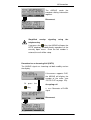
9 Single Tests
9.3.1 Start BERT
The following parameters are required for the BERT:
- Duration of the BERT (default setting = 1 minute)
- Error level: If the bit error rate exceeds this limit, the
ARGUS will display the test result NO. If the bit error
rate is less than this limit, the ARGUS will display an OK
-
(default setting = 10-05)
HRX value in % (hypothetical reference connection see
ITU-T G.821) (default setting = 15%)
Bit pattern, which will be sent during the test
(default setting = 215-1)
The parameters can be changed individually and saved (see
“Configuration: BERT” on page 119.).
In the Single tests menu,
use the < ↓ > to select Bit
error test.
Use < ↓ > to select BERT
start.
Enter your
Own number to perform the
BERT in an extended call to
oneself (two B-channels).
ora
remote number for a BERT
to a loopbox (one B-channel)
or end-to-end
Confirm the number
Using the < ↓ > , select the
service which should be
used for the BERT.
Confirm the service.
Enter the B-channel on the
keypad. If you enter an *, the
ARGUS will choose any Bchannel that is free.
BERT start
60
ARGUS 3u plus/3u NT
9 Single Tests
After the ARGUS has setup
the
connection
and
synchronized the send and
receive directions, it will
display the bit pattern, the Bchannel used (e.g. B02), the
remaining test time in
h:min:sec, the number of bit
errors that have occurred
(e.g. 3), the synchronicity of
the bit pattern (synchronous
or asynchronous) and the
LOS-counter (e.g. 5).
If you press < ERROR > , the ARGUS will generate an
artificial bit error, which can be used to test the reliability of
the measurement (in particular for end-to-end tests).
Press < TM > to start the Test Manager
(see “Test Manager” on page 94. )
Press < ABORT > to stop the BERT
0 -Key: Restarts the bit error test. The test time and number
of bit errors will be reset.
When a bit error is detected, this will be signaled
by a brief alarm; in the event that the
synchronisation is lost, a constant alarm will sound
((see page 127 Alarm bell)).
ARGUS 3u plus/3u NT
61
9 Single Tests
After the test time is over, the
ARGUS will display the
cause and the location which
initiated the disconnect.
If the test ran normally, the
ARGUS will display “Active
clearing” on this line.
The test results display:
The bit pattern (e.g. 2^15),
B-channel used (e.g. 02),
Transferred data in KBit (e.g.
10309 KB, K= 1024* bits),
The number of bit errors
(e.g.10),
The bit error rate (e.g. 9.7E07 = 9.7·10-7 = 0.00000097),
The evaluation of the results
depends on the error
threshold (OK).
Display
of
other
characteristic
values
(in
accordance
with
ITU-T
G.821)
All values are given in
percentages.
The
ARGUS
evaluates
whether the test results
satisfy the limits specified in
the CCITT G.821/G.826
under consideration of the
reference connection HRX
(displaying OK or NO).
↓ -Key: Scroll
<MENU>:
The
ARGUS
returns to the BERT menu.
HRX
Defines the hypothetical reference connection
EFS
Error Free Seconds
The number of seconds in which no error occurred.
ES821 Errored Seconds
The number of seconds in which one or more errors
occurred.
62
ARGUS 3u plus/3u NT
9 Single Tests
SES821 Severely Errored Seconds
The number of seconds in which the bit error rate is
>10-3. In one second, 64,000 bits are transferred,
thus BitERror=10-3 equates to 64 bit errors.
US
Unavailable Seconds
The number of sequentially adjacent seconds (at
least 9 sec) in which BER>10-3.
AS
Available Seconds
The number of sequentially adjacent seconds (at
least 9 sec) in which BER<10-3.
DM
Degraded Minutes
The number of minutes in which the bit error rate is
>10-6.
In one minute, 3,840,000 bits are transferred, thus a
BER = 10-6 corresponds to 3.84 bit errors (3 errors =
NO (no DMs), 4 errors = OK (DM)).
LOS
Loss of Synchronisation
Synchronisation is lost at an error rate > or = 20%
within a second. The absolute number of
synchronisation losses will be shown.
ARGUS 3u plus/3u NT
63
9 Single Tests
9.3.1.1 BERT - saving
The ARGUS can store the results of several BERTs.
The ARGUS saves the results together with the date, time (if
the network supplies the date and time) and the call number
of the access under test (if this number has been entered as
the "own" number in the speed-dialing memory) under the
next free record number (see “Automatic Test” on page
99.). If all of the records are used, the ARGUS will return to
the Autom. Test dialog and request permission to overwrite
the oldest test results.
The ARGUS is displaying
the result window.
-Key
Press <YES>
saving
64
BERT
-
ARGUS 3u plus/3u NT
9 Single Tests
9.3.1.2 Display the saved BERT results
see “Display Results” on page 104.
Use the < ↓ > in the Main
menu to select Automatic
tests.
Use the < ↓ > to select the
record with the saved BERT
results.
Using the < ↓ >, select the
Display result.
The ARGUS will first display
the status of the access
under test.
Display the
stored results
Use the ↓ -Key to scroll
through the results.
Quit the results display.
ARGUS 3u plus/3u NT
65
9 Single Tests
9.3.2 BERT wait
In BERT wait mode, the ARGUS will wait for the BERT at
the remote end which is necessary for an end-to-end test:
In the Single tests menu,
use the < ↓ > to select Bit
error test.
Open the
menu.
Bit
Using the < ↓
BERT wait.
error
test
>, select
Activate "BERT wait“
Operating
mode
BERT wait
The ARGUS first waits for a
call and then sets up the
connection.
During the connection, the
received bit pattern will be
evaluated and another bit
pattern will be sent.
If you press <MENU>, the
ARGUS will return to the
Main menu; the test "BERT
wait“ remains active. In the
Main menu, if < TM > is
pressed, the ARGUS will
return to the display "BERT,
Wait active", see Page 98.
< TM
>: Calls the Test
Manager (Page 94)
The ARGUS displays that will appear are the same as those
in Chapter 9.3.1 Start BERT .
66
ARGUS 3u plus/3u NT
9 Single Tests
9.3.3 B-channel loop
B-channel loop mode is required in order to run a bit error
test using a loopbox at the remote end as well as to test
permanent circuits.
Use the < ↓ > to select Bchannel loop
.
Activate the "B-channel
LOOP“
Operating
mode
B-channel
The ARGUS will wait for a
call. Any incoming call
(regardless of the service)
will be taken immediately.
The ARGUS will switch a
loop back in the B-channel
that is specified by the
exchange and then send the
received bit pattern back to
the caller/sender.
If you press < MENU >, the ARGUS will return to the Main
menu; the test "B-channel-LOOP “ remains active. In the
Main menu, if < TM > is pressed, the ARGUS will return to
"B-channel-LOOP, Wait active", see Page 98. From this
menu, you can start a second B-channel loop connection
(this is also possible using < TM > ).
< TM >: Call the Test Manager
If the ARGUS takes a call, it will open the B-LOOP connect.
window, which is similar to the normal connection window:
The ARGUS will display the
caller's number (e.g. 2351
90700) , the B-channel used
(e.g. B01) and the number
dialed (e.g. 907070).
↓ -Key: Display additional
information (e.g. UUS…)
< TM
>: Call the Test
B-channel loop
Manager
Connection
< Menu >: The ARGUS
stop
returns to the main menu.
Operating mode
B-channel LOOP
still active
ARGUS 3u plus/3u NT
67
9 Single Tests
9.4 X.31 Test
The ARGUS will either perform a “Manual X.31 Test” or an
“Automatic X.31 Test”:
In the case of an automatic test, the ARGUS will first setup
the D-channel connection and then begin setting up the
X.31 connection. Afterwards, the ARGUS will automatically
clear the connection and display the results.
In the case of a manual test, the ARGUS will setup a Dchannel connection and an X.31 connection. The duration of
this connection is determined by the user (or the opposing
end). For the duration of the connection, the ARGUS will
repeatedly send a predefined data packet. The ARGUS will
count all of the data packets sent and received and will
display (where possible) the contents of the data packets
received.
9.4.1 Automatic X.31-Test
The “X.31 Automatic, D-channel” test consists of two steps:
First step: The ARGUS tests whether it is possible to
access the X.25 service via the D-channel on
the BRI access under test.
The ARGUS sequentially checks all the TEIs
from 0 to 63. All the TEIs with which the X.31
service is possible on Layer 2, will be displayed.
Second step: For each TEI with which X.31 is possible on
Layer 2, a CALL_REQ packet will be sent and
then the ARGUS will wait for an answer.
Beforehand, the ARGUS will request the entry
of the X.25 access number, which will be saved
in speed-dialling memory under X.31 test
number (“Saving Call Numbers” on page 129).
With the entry of the X.25 access number, you
can - if you wish - select a logical channel (LCN)
other than the default.
68
ARGUS 3u plus/3u NT
9 Single Tests
In the Single tests menu,
use
< ↓ > to select the X.31 test.
Use < ↓
> to select
Automatically.
Start test
The test can take up to 4
minutes (a rotating bar will
be displayed). Beginning on
the left, the ARGUS will
display the TEI currently
being tested followed by the
one previously tested and its
result:
+ = X.31 is available for this
TEI
- = X.31 is not available for
this TEI
Once the test has ended, the
ARGUS will show whether
the X.31 service is available
for Layer 3 for the TEIs
found in Step 1.
Using the <↓>, scroll through
the results.
Test results:
TEI 02 = the first valid TEI value is 02.
++
= Both test steps were successful
+= the first test step was successful, the second step
not In this case, the ARGUS will display the relevant
X.31 cause for the failure (in the example above: 13)
and an associated diagnostic code (in the example:
67), if there is one (see “X.31 Test – Error
messages” on page 145.).
If the X.31 service is not supported, the ARGUS will report
"X.31 (D) n. impl.“.
ARGUS 3u plus/3u NT
69
9 Single Tests
9.4.2 Manual X.31 Test
In this test variant, the ARGUS first requests a TEI, LCN and
an X.31 number (The ARGUS uses the TEI and LCN values
stored in the Configuration/X.31 as default values - seePage
125) and the call number saved as the X.31 number in the
speed-dialing memory (see Page 129). If a “ ** ” is entered
for the TEI, the ARGUS will automatically determine a TEI.
Using the first TEI with which X.31 is possible, the ARGUS
will begin to setup a connection.
In the Single tests menu,
< use ↓ > to select the X.31
test
.
With the < ↓
Manual.
>, select
The ARGUS displays the
stored TEI.
You can edit the TEI from
the keypad; If you enter **,
the
ARGUS
will
automatically determine a
TEI.
< DEL >: Delete the TEI
The ARGUS displays the
stored LCN.
It is possible to edit the LCN
from the keypad.
Display of X.31 Number
(see speed-dialing memory
Page 129). It can be edited
from the keypad.
Setup a X.31 connection
The ARGUS will display the
LCN, TEI and X.31 number
(e.g. 0263110 00091258).If
you
select
<DATA>,
predefined data packets will
be sent.
70
ARGUS 3u plus/3u NT
9 Single Tests
-Key
The ARGUS will count the
data packets sent and
received and will display
(where possible) the contents
of the data packets received.
The ARGUS will display the
number of packets sent (e.g.
3), the number of packets
received (15) and their
contents (in ASCII).
The contents of the received
data packet (in hexadecimal)
The connection will be
maintained until the user or
the opposing end clears it.
When the X.31 connection is
cleared, the ARGUS will
automatically clear the Dchannel connection.
ARGUS 3u plus/3u NT
71
9 Single Tests
9.5 CF Interrogation
The ARGUS will check whether a call diversion has been
setup in the exchange for the access under test (BRI or UInterface).
The type of diversion (CFU, CFNR or CFB ) and the call
diversion's service will be shown in the display. The display
is limited to a maximum of 10 call diversions for all of the
MSNs.
The ARGUS will count any additionally setup call
diversions.
The ARGUS can clear any call diversion setup in the
exchange.
In the Single tests menu, use
the < ↓ > to select CF
interrogat.
Start the
CF interrogation;
The test can take several
seconds.
The ARGUS displays the
type (e.g. CFU) and service
(e.g. Spch) of the call
diversion, which in this
example is the third of a total
of nine found (3/09).
The number 2351919658 is
diverted to 14418.
The ↓ -Key is used to scroll
though the display.
Press < NEW > to repeat the
CF interrogation.
Delete a call diversion
Security query
Press < ALL > to delete all
call diversions.
The ARGUS will delete the
displayed number in the
exchange.
If the call diversion cannot be
cleared, the ARGUS will
report: "Call diversion
not changeable!".
72
ARGUS 3u plus/3u NT
9 Single Tests
Some PBXs or exchanges do not permit the use of
the mechanism used (by the ARGUS) for the
interrogation of the call diversions for all MSNs or
they return a negative acknowledgment of the
interrogation of call diversions, implying that no call
diversions have been setup.
In the event of a negative acknowledgment, the
ARGUS will, therefore, request that the Own MSN
be entered.
The call diversion interrogation will be repeated
MSN-specific.
Naturally, in this case, the results of the interrogation
of the call diversion only apply for the entered MSN
and not for the entire access.
Abbreviations used for the services and service groups
on the display:
Basic Service
Abbreviation
All services
All
Voice (speech)
Spch
Unrestricted digital information
UDI
Audio 3.1 kHz
A3k1H
Audio 7 kHz
A7khz
Telephony 3.1 kHz
Tel31
Teletext
TTX
Fax Group 4
FaxG4
Video syntax based
Video Telephony
ViSyB
ViTel
Telefax Groups 2/3
FaxG3
Telephony 7 kHz
Tel7
UDI 64 kBit
UDI
Unknown Basic Service
Unkno
ARGUS 3u plus/3u NT
73
9 Single Tests
9.6 CF - Activation
Using the ARGUS, call diversions can be setup in the
exchange (BRI or U-Interface).
In the Single tests menu, use
> to select CF
the <↓
activation.
Using the <↓ > select the
type of call diversion (e.g.
SPch).
Using the < ↓ > select the
type of call diversion (e.g.
CFU).
Under "Own number", enter
the number which should be
diverted.
Press <DEL > to delete the
digit before the cursor.
Enter the number to which
calls should be diverted.
Setup the call diversion
The ARGUS returns to the
Single tests menu.
74
ARGUS 3u plus/3u NT
9 Single Tests
9.7 CF - Delete
Using the ARGUS, selected call diversions can be deleted/
cleared in the exchange (BRI or U-Interface).
In the Single tests menu, use
the <↓ > to select CF delete.
Using the < ↓ >, select the
service of the call diversion
(e.g. SPch).
Using the < ↓ > select the
type of call diversion (e.g.
CFU).
Under "Own number", enter
the number which should no
longer be diverted.
Press <DEL > to delete the
digit before the cursor.
Delete a call diversion
ARGUS 3u plus/3u NT
75
9 Single Tests
9.8 MSN Interrogation (only on a BRI with DSS1)
On a P-MP access using the DSS1 protocol, the ARGUS
will determine the MSNs of the access under test. It will
display a maximum of 10 call numbers. Depending on the
Type of Number (TON), the ARGUS will display the call
numbers in different versions:
• only the MSN (without area code)
• with national area code without leading the “0”
• with country code without leading the “00”
• complete call number
In order to interrogate the MSNs, the access under test must
support the supplementary service “Call Forwarding (CF)”.
In the Single tests menu,
use the < ↓ > to select MSN
interrogat.
Start
the
interrogation
MSN
In this example, the ARGUS
displays the first MSN
(2351919658) of a total of
three found (1/03).
Using the < ↓>, scroll
through the results.
Press < NEW > to repeat the
MSN interrogation.
Due to differences in the protocol, some exchanges
do not support MSN interrogation.
In this case, the ARGUS will report: MSN
interrogation not possible!
76
ARGUS 3u plus/3u NT
9 Single Tests
9.9 Time measuring
The ARGUS measures three different times:
-
Connection setup time
Propagation time of the data and
Transit time differential (interchannel delay) of the
data in two B-channels.
Time measurements on a BRI or U-Interface access are only
possible in TE mode.
ARGUS 3u plus/3u NT
77
9 Single Tests
9.9.1 Connection setup time
The ARGUS places an outgoing call and measures the time
between sending the SETUP and receiving the ALERT or
CONN. The ARGUS disconnects automatically as soon as
the measurement is completed.
In the Single tests menu, use
the < ↓ > to select Time
measuring.
Use the < ↓ > to select
Conn.setup time.
Enter - or select from the
speed-dialing memory - the
call number for the outgoing
call
Use the < ↓ > to select the
service.
Enter the B-channel on the
keypad.
Perform measurement
The ARGUS will display the
connection setup time in
seconds and the received L3 messages (end of connection
setup).
If the ARGUS cannot perform the measurement (e.g.
because the call number entered was wrong or no Bchannel was free) the corresponding cause will be
displayed.
78
ARGUS 3u plus/3u NT
9 Single Tests
9.9.2 Time measurement: B-channel delay
The ARGUS places a call to itself (self call) or to a remote
loopbox and measures the propagation delay for the data in
the selected B-channel.
The ARGUS disconnects automatically as soon as the
measurement is completed.
In the Single tests menu, use
the < ↓ > to select Time
measuring.
Use the < ↓ > to choose
Interchan.dela.
Enter own number for self
calls or remote number for
connections to a remote
loopbox.
Use the < ↓ > to select the
service.
Enter the B-channel on the
keypad.
Perform measurement
The ARGUS displays the
propagation
delay
in
milliseconds and in bits
(multiples of the time required
to send a bit at 64 kBit/s).
(The time for sending 1 bit at
64 kBit/s = approx. 15.26 µs.)
ARGUS 3u plus/3u NT
79
9 Single Tests
Press <ABORT> to stop the
measurement.
If the ARGUS cannot perform the measurement, e.g.
because the call number entered was wrong or no Bchannel was free, the corresponding cause will be
displayed.
When it is connected to a loopbox, if the ARGUS does not
receive the data back within 13 seconds, it will display the
message “No LOOP”.
80
ARGUS 3u plus/3u NT
9 Single Tests
9.9.3 Time measurement: Interchannel delay
The ARGUS establishes two separate connections to a
remote loopbox. The loopbox sends the respective Bchannel data back on the same channel. The ARGUS
measures the propagation delay for the data on each of the
B-channels and determines the difference between the two
propagation delays (interchannel delay).
The ARGUS disconnects automatically as soon as the
measurement is completed.
In the Single tests menu, use
the < ↓ > to select Time
measuring.
Use the < ↓ > to select
Interchan.delay.
Enter - or select from the
speed-dialing memory - the
call number of the loopbox
Use the < ↓ > to select the
service.
Perform measurement
The ARGUS displays the
propagation
delay
in
milliseconds and in bits
(multiples of the time required
to send a bit at 64 kBit/s, it
takes 15.26 µsec to send a
bit).
The measurement will be
repeated in cycles.
Press <ABORT> to stop the
measurement.
ARGUS 3u plus/3u NT
81
9 Single Tests
If the ARGUS cannot perform the measurement - e.g.
because the call number entered was wrong or no Bchannel was free - the corresponding cause will be
displayed.
When it is connected to a loopbox, if the ARGUS does not
receive the data back within 13 seconds, it will display the
message “No LOOP”.
82
ARGUS 3u plus/3u NT
10 Connection
10 Connection
10.1 Setting up an ISDN connection
a) The ARGUS can setup a connection for the following
services:
Service
Name in the
ARGUS
display
abbreviation
/
Language
Language / Lang
Unrestricted Digital
Information
UDI 64kBit / UDI 64
3.1 kHz Audio
Tel.analog / Tel.
7 kHz Audio
7 kHz audio / 7 kHz
Unrestricted Digital
Information with tones /
Display
UDI+TA / UDI TA
Telephony
Tel.ISDN / Tel.
Facsimile Group 2/3
Fax G3 / FaxG3
Facsimile Group 4 Class 1
Fax G4 / FaxG4
Teletex service basis and
mixed mode and facsimile
service Group 4 Classes II
and III
Mixed Mode / Mixed
Teletex Service basis mode
Teletex / Ttx64
International inter working for
Videotex
Videotex / Vidtx
Telex
Telex / Telex
OSI application according to
X.200
OSI / OSI
7 kHz Telephony
Tel.7kHz / Tel7k
Video Telephony,
first connection
Videotel.1 / Vid.1
Video Telephony,
second connection
Videotel.2 / Vid.2
Additional three user-specific services (see “Services” on
page 117.)
ARGUS 3u plus/3u NT
83
10 Connection
b) The integrated handset can be used as a phone during
a telephone connection.
c) When an ISDN connection is setup, pressing the
number keys (0-9) or the * or # will generate and send
the corresponding DTMF tones.
84
ARGUS 3u plus/3u NT
10 Connection
Procedure for an Outgoing Call (ISDN)
1) Overlap sending:
In overlap sending, the digits of the call number are sent
individually.
In the Single tests menu,
use the <↓ > to select
Phone / connec.
Use the < ↓ > to select
Overlap sending. If the
-Key
-Key is pressed the
ARGUS will open the
Connection menu.
Using the < ↓ > select the
service that should be
used for the connection.
Using the keypad, enter
the B-channel (by default,
the last B-channel used
will be suggested)
When entering a new Bchannel,
first
press
<DEL>.
If you enter an *, the
ARGUS will choose any
B-channel that is free.
The ARGUS will show
whether the B-channel is
available.
Disconnect
ARGUS 3u plus/3u NT
Setup the connection
Enter the number
on the keypad.
The ARGUS displays the
service (e.g. Tel.), the
own number (90700), the
B-channel (B02) and the
number called (01191).
The ↓ -Key is used to
scroll
though
the
information.
<TM >: to start the Test
Manager (Page 94).
85
10 Connection
The connection is
using B-channel 2.
-Key
setup
The ARGUS will display
additional
information
(if
there is any)
The ARGUS displays the
sub-address of the caller
(808076) and the destination
address (01191).
-Key
Display of the
- User-to-User Information
- Display Information
- Type of number (TON)
- Numbering Plan (NP)
-Key
- Advice of charges:
If the charges are not given
in units,
rather directly as currency,
the ARGUS will display the
current charges in currency.
If, in DSS1, the call charges
are
not
provided
in
accordance with the ETS
300 182 standard, rather in
the form of the information
element DISPLAY (DSP), the
ARGUS will display the
DISPLAY
message's
character string.
Disconnect
The ARGUS displays the
cause of the disconnect.
(see page 90 Clearing down
an ISDN connection)
86
ARGUS 3u plus/3u NT
10 Connection
Note regarding the entry of the call number
Separate the extension from the access number
with a # (e.g. 02351 / 9070-20 is entered on the
ARGUS as: 023519070 #20). For an outgoing call,
the ARGUS uses the entire call number (without #)
as the number called (CDPN or DAD) and, for the
calling number, only the extension (DSS1-CGPN or
1TR6-OAD).
A ‘#‘ at the beginning of a call number is treated as a
valid character. A ‘#’ at the end of the own call
number instructs the ARGUS to not send the caller’s
number for outgoing calls (CGPN or OAD).
Simplified overlap signaling using the telephone
key
If you press the
-Key, the ARGUS will open the
Connection/Overlap window directly regardless of
the currently open menu.
If you press the
-Key again, you will hear the dial
tone. Once you enter a call number, the connection
will be setup.
ARGUS 3u plus/3u NT
87
10 Connection
2) Enblock
In en-bloc signalling, the ARGUS sends the entire dialing
information in one block.
The number is dialed from the call number memory (see
“Saving Call Numbers” on page 129.).
In the Single tests menu,
use the <↓ > to select
Phone / connec.
Use the < ↓ > to select
Enblock signalling.
Use the
-Key to select
the number from the call
number
memory
or
reenter the number on the
keypad.
Press <DEL> to delete a
digit.
-Key
If the
-Key is pressed
the ARGUS
will open the Connection
menu.
Using the < ↓ > select the
service that should be
used for the connection.
Enter the B-channel on
the keypad.
(See Overlap sending for
entries)
Start
the
dialing
procedure
(for more displays and
information see Overlap
sending)
Disconnect
The ARGUS displays the
cause of the disconnect.
(see page 90 Clearing
down
an
ISDN
connection)
88
ARGUS 3u plus/3u NT
10 Connection
Procedure for an Incoming Call (ISDN)
An incoming call can be taken at any time even when a test
(e.g. BERT) is in process (see “Simultaneously Starting
Several Tests” on page 95.).
The ARGUS will signal an incoming call with an audible tone
and a message on the display.
On a P-MP access, you can use the Call acceptance (see
“Call Acceptance” on page 118.) function to configure the
ARGUS to only signal incoming calls which are addressed to
the MSN that corresponds to your own call number. This
function can only be used when your own call number has
been entered into the ARGUS’s speed-dialing memory (see
“Saving Call Numbers” on page 129.) and the incoming call
has a destination MSN.
Reject call
The ARGUS displays the
service (Tel.), the number of
the caller (02351907070), the
B-channel used (B01) and
the number called (90700).
The ARGUS will display the
number
called
(DDI)
completely, if the Alerting
mode is set to manual
.
(see Page 116).
-Key: View additional
information (if available)
Accepting call
Use the < TM > softkey to
start the Test Manager.
(see Page 94).
Use the
< ↓ > to view
additional information.
Clearing the connection
Charge information in NT mode (optional):
In NT mode, the ARGUS will – for incoming calls – send
advice of charges in accordance with DSS1 as units and as
currency (in euro).
ARGUS 3u plus/3u NT
89
10 Connection
10.2 Clearing down an ISDN connection
To
clear
down
the
connection, press <CLEAR>
or the Press the
-Key
The ARGUS will display the
cause (see the table below)
of the disconnect (e.g.
Normal clearing) and the
location where the cause
occurred (e.g. subscriber).
-Key: View additional
information (e.g. charges, if
available)
< TM
>: Open the Test
Manager
The ARGUS returns to the
Single tests menu.
The following causes are shown in clear text:
Cause
Display
Explanation
255
Active clearing
Clearing User actively initiated
the disconnection
Long 0 Normal clearing
Cause element with Long 0 is
mostly used by 1TR6
01
Unalloc. number
“No access under this call
number” is signaled
16
Norm. clearing
Normal disconnect
17
User busy
The number called is busy
18
No user respond
No answer from the number
called
19
Call.time XX
Call time too long
21
Call reject
The call is actively rejected
90
ARGUS 3u plus/3u NT
10 Connection
28
Wrong number
Wrong call number format or
call number is incomplete
31
Norm. clearing
Unspecified “normal class”
(Dummy)
34
No B-chan.avail.
No circuit / B-channel
available
44
Req.chan.unavail Requested B-channel not
available
50
Req.fac.not subs
Requested supplementary
service (facility) not
subscribed
57
BC not authoriz.
Requested bearer capability is
not
enabled
63
Srv./opt.n.avail
Unspecified
for “Service
not available” or “Option not
available”
69
Req.fac.not impl.
Requested facility is not
supported
88
Incompat.
Objectives
Incompatible destination
102
Timer expired
Error handling routine started
due to time-out
111
Protocol error
Unspecified for ”protocol error
class”
127
Interworking err
Unspecified for
“interworking class”
Other causes are not shown in clear text, rather as decimal
codes (see Appendix B and C).
ARGUS 3u plus/3u NT
91
10 Connection
10.3 Operation on a POTS (analog) access
Procedure for an Outgoing Call (POTS)
The ARGUS sets up a connection to another terminal. If the
terminal is a telephone, the handset integrated in the
ARGUS can be used to hold a conversation.
In the Main menu, use the
< ↓ > to select Single tests
Setup the connection
Enter the number on the
keypad.
Each
of
the
number's digits will be dialed
individually. The ARGUS will
display the number dialed.
As soon as the remote party
answers, a voice connection
will be set up.
The ARGUS will display the
charges, if the information is
available on the access
under test.
< R >: Generate a
FLASH signal
< MEM >: Select the number
from
the
call
number
memory or reenter the
number on the keypad.
Use the < ↓ > to scroll.
Press <DEL> to delete a
digit.
The last number dialed will
always be used as the
default - simplified last
number redial.
92
ARGUS 3u plus/3u NT
10 Connection
The ARGUS sends the
complete dialing information
together.
Disconnect
Simplified overlap
telephone key
signaling
using
the
If you press the
-Key, the ARGUS will open the
POTS telephony window directly regardless of the
currently open menu. Once the call number is
entered, the call will be setup.
Procedure for an Incoming Call (POTS)
The ARGUS signals an incoming call both audibly and on
the display.
If the access supports CLIP,
the ARGUS will display the
number of the caller (see
“POTS CLIP” on page 123).
Or
press
the
-Key
Accepting call
< R >: Generates a FLASH
signal
Disconnect
ARGUS 3u plus/3u NT
93
11 Test Manager
11 Test Manager
The ARGUS can simultaneously start fully independent BRI
or U-interface access tests or “connections”.
As an example, a BERT can be run at the same time that
you make a phone call. The individual tests or “connections”
use resources.
All of the tests that have been started will be administered
by the Test Manager. Using the Test Manager you can start
new tests, switch between tests running in parallel or
terminate all of the tests that are currently running.
In the Main menu, use the <
↓ > to select the
Test Manager.
Open the Test Manager
If the ARGUS is in the Connections or Single tests
menu (or in a test), the Test Manager can be
opened using the 6-Key or via the <TM> softkey.
94
ARGUS 3u plus/3u NT
11 Test Manager
11.1 Simultaneously Starting Several Tests
Starting a new test or connection during an existing
connection
Example:
There is a connection on Bchannel 1.
During this connection, the
Test Manager can be started
by pressing the
the <TM> softkey.
-Key or
The ARGUS displays the
number
of
existing
connections (-/01).
Use the < ↓ > to select Start
new one.
The ARGUS returns to the
main menu.
Use the < ↓ > to select
Single tests.
Use the < ↓ > to select the
desired test (e.g. bit error
rate test) .
Start test
(Still connected)
For information on the
operation of bit error tests,
see Page 60
The ARGUS opens to the
Test Manager.
Use the < ↓ > to select
Outgo.connect.
The connection was started
first (1/02), there are 2
connections / tests (1/02).
The connection uses Bchannel 1 (B01).
ARGUS 3u plus/3u NT
95
11 Test Manager
The ARGUS will return to
the
Connection window.
If a test (or connection) is cancelled/cleared, the ARGUS will
return to the Test Manager if there is another test (or
connection) running in the background.
Some tests use so many resources that they cannot
be run in every combination with other tests. In this
case, the ARGUS will display the message “Test not
possible at this time”.
Test/
Connection
Number of times that It is possible
this test/connection can to change to
be started at the same another test
time
Incoming call
2
Yes
Outgoing call
2
Yes
BERT
2
Yes
LOOP
2
Yes
Service Tests
1
No
Suppl.serv.test
1
No
Time
measurement
1
No
X.31 Test
1
No
CF
Interrogation
1
No
Auto. Test
1
When the Auto. Test is
running
all
of
the
resources are in use and
no
other
tests
or
connections are possible
No
BRI level
1
No
POTS voltage
1
No
96
ARGUS 3u plus/3u NT
11 Test Manager
Accepting an incoming call/connection when a test is
running.
The ARGUS signals an incoming call both audibly and on
the display (see Chap. 10.1 Setting up an ISDN connection
page 83).
The incoming call can be accepted without influencing the
currently running test. If either the B-channel loop or BERT
wait function is active, the call will be accepted
automatically.
The manner that multiple connections are handled is
illustrated in the following example of "Accepting an
incoming call during a BERT", but it is identical for all other
tests.
While running a BERT, the
ARGUS displays information
about an incoming call.
<REJECT >: To reject the
incoming call. The ARGUS
will return to the BERT.
Accepting call
The BERT will continue in
the background.
To switch to the BERT
or
-Key
Use the < ↓ > to select
BERT outgoing.
The ARGUS jumps to the
BERT
The connection is still active
in the background, the
handset is still switched to
the connection.
ARGUS 3u plus/3u NT
97
11 Test Manager
If available, the internal handset will be assigned to
the currently started (voice) connection. The
assignment of the handset to a given connection is
also retained in the background.
11.2 Switching Between Tests
Open the Test Manager.
Using the <↓ >, select the
Test (Connection) that you
wish to switch to.
If you press the < ✓ >, the
ARGUS will open the
selected test.
>: The ARGUS
With <
will return to the point from
which the Test Manager was
called (e.g. to a test running
in parallel). If no other test is
running, the ARGUS will,
reasonably enough, return to
the Main menu.
11.3 Cancel All
Open the Test Manager.
Using the < ↓ >, select
Cancel all.
The ARGUS will cancel all of
the currently running tests
and/or current connections
and then return to the Main
menu.
98
ARGUS 3u plus/3u NT
12 Automatic Test
12 Automatic Test
The ARGUS performs an automatic test series and displays
the test results.
Using the intec software, WINplus or WINanalyse, the test
results can also be saved on a PC, where they can be
presented in a comprehensive measurement report and
printed.
The ARGUS automatically performs the following sequence
of tests:
On a BRI or U interface access (ARGUS in TE mode)
- Status
- Level Measuring
- Service Tests
- BERT in an extended call to oneself
- Test the Supplementary Services
- CF Interrogation (Call Diversions)
- MSN Interrogation
- X.31 test
On a BRI or U-interface permanent circuit
-
Status
Level Measuring
BERT in end-to-end mode (e.g. with a loopbox on the
remote end)
The ARGUS saves the test results together with the date
and time (supplied by the exchange). Additionally, settings
such as your own plus a remote call number will also be
saved.
The test results are not lost when the ARGUS is
switched off.
The ARGUS saves the results of multiple test series
(records 1,2,3...).
Each function in the Automatic test menu refers to one of the
test series saved as a record.
Therefore, the first step will open a dialog in which you must
select the desired data record.
ARGUS 3u plus/3u NT
99
12 Automatic Test
Use the <↓> to select
Automatic tests.
or press 4 to start an
automatic test series.
Use the < ↓ > -Key to select
the record holding the saved
test results.
Press < NUMBER > to display
the number of the access
under test
Empty records are labeled as
"free“.
100
ARGUS 3u plus/3u NT
12 Automatic Test
12.1 Automatic Start test
You should check the required parameters (e.g. BERT
measurement time and error level, see Page 120 and Page
120) before the automatic test series is begun.
Use the< ↓ > to select Start
(in the example, the new test
is saved in record number 2).
Enter Own number - on
accesses using the DSS1
protocol - also enter a
remote number.
Use the < ↓ > to select the
service.
(needed
for
the
suppl.serv.test)
Start test
During the test series, the
first three lines in the display
will reflect the Single test
currently being run.
To interrupt the test, press
<ABORT>.
ARGUS 3u plus/3u NT
101
12 Automatic Test
Terminating the test (early):
The ARGUS is running an
automatic test.
Interrupting a test
Use the < ↓ > to select
Interrupt test.
Press the < ABORT> softkey
to restart the test.
Stop test
Any test results already
determined will not be
saved.
Any “old” data stored
under this data record
number from a prior test
will be retained.
Skipping individual tests:
A single test can be skipped:
In this example, the ARGUS
is running a Service check.
Interrupt the Service check
Use < ↓ > to select Stop cur.
test
Use < ABORT > continue the
Service check
The ARGUS will skip the
Service check.
The next single test (e.g.
BERT) will be started.
102
ARGUS 3u plus/3u NT
12 Automatic Test
Resuming a test:
An interrupted Single test
can be resumed:
In this example, the ARGUS
is running a Service check.
Interrupting a test
Use <↓> to select Continue
test.
Press the < ABORT > softkey
to restart the test.
The ARGUS repeats the
“disturbed“ single test (in the
example: the Service check).
ARGUS 3u plus/3u NT
103
12 Automatic Test
12.2 Display Results
The ARGUS displays the results stored for the single tests in
the following order:
For: - BRI or U-interface - Permanent circuit
- State
State
- Level measuring
Level measuring
- Service Check
BERT
- BERT
- Suppl.serv.test
- X.31-Test
- CF Interrogation
- MSN Interrogation
Displaying the saved test results
In the Main menu, use the <
↓ > to select
Automatic
tests.
Use the ↓-Key to select the
stored record.
Use the < ↓ > to select
Display result.
Display the test results
The ARGUS will first display
the status of the access
under test.
Display result of the next
single test
e.g. display Service check.
Use the <↓> to scroll through
the Single test results.
If you press <CONT. >, the
ARGUS will display the
results of the next single test.
104
ARGUS 3u plus/3u NT
12 Automatic Test
12.3 Sending the results of a tests to a PC
To visualize and archive the test results on the PC, the data
records can be transferred to the PC via the serial interface
using the included cable (labeled as PC Interface) (connect
the cable between the ARGUS “L-Test” jack ---- PC’s serial
interface).
Connect the ARGUS to your PC and start the ARGUS
WINplus program.
In the Main menu, use the
< ↓ > to select Automatic
tests.
Use the ↓-Key to select the
record (e.g. No. 2).
Use the < ↓ > to select Test
data to PC.
Start transfer
data to PC
ARGUS 3u plus/3u NT
of
105
12 Automatic Test
12.4 Deleting the results of a test
In the Main menu, use the <
↓
> to select Automatic
tests.
Use the ↓-Key to select the
record (e.g. No. 2).
Use the < ↓ > to select
Delete.
Delete record (No. 2)
For information on how to delete all records, please see on
page 131 “Reset”.
106
ARGUS 3u plus/3u NT
12 Automatic Test
12.5 Sending the results of all tests to a PC
The ARGUS will send the results of all of the tests to the PC
at one time (connection cable see Page 105).
In the Main menu, use the
<↓> to select Automatic
tests.
Use the ↓-Key to select the
record.
Use the < ↓ > to select All
tests to PC.
Start transfer
data to PC
ARGUS 3u plus/3u NT
of
107
13 Level Measuring
13 Level Measuring
13.1 Level measuring on a BRI access
Level measurement – connected line
The ARGUS measures the level of the received useful
signal. In TE mode, it also measures the phantom feed. The
measurement will be updated continuously.
In the Main menu, use the <
↓
> to select Level
measuring.
Start measurement
The ARGUS will display the
level of the useful signal (e.g.
0.64 V) and the level of the
feed (e.g. 38.2 V).
<
R>ON
>: add 100Ω
resistor
< R>OFF >: remove 100Ω
resistor
Press <NEW> to setup Layer
1 again - to ensure a
reasonable measurement.
Measurement results:
- Evaluation of the useful signal level:
<< level is too low
>> level is too high
OK Level is in order (0.75V
+20%
-33%
i.e.
-13.75%
i.e.
from 0.9 V to 0.5 V)
__ no voltage
- Evaluation of the level of the feed
- Type of feed:
NORM Normal feed (40V
+4.25%
from 41.7 V to 34.5 V)
REV_ inverted phantom feed
NONE no feed
108
ARGUS 3u plus/3u NT
13 Level Measuring
13.2 Voltage measurement on a U-interface
Measurement of feed voltage on a U-interface
Use the <↓ > to select
Voltage U.
Start measurement
The ARGUS will display the
level of the feed in volts.
The measurement will be
updated continuously.
Measurement of the U-interface under load
The ARGUS measures the voltage on the U-interface under
various selectable loads and also displays the calculated
current and power.
From these values, it is possible to estimate the length of the
line.
Use the <↓> to select Power
U.
Start measurement
The ARGUS displays the
switched-in load in kΩ, the
measured voltage in Volts
(should not
>100V),
the
calculated power in mW and
the calculated current in mA.
Use <++> to increase the
load by one increment (the
resistance is lowered)
Use <--> to decrease the
load by one increment (the
resistance is increased)
ARGUS 3u plus/3u NT
109
13 Level Measuring
Step Load / kΩ Maximum Voltage / V
1
64
ca. 126.0 1)
2
28
ca. 126.0 1)
3
19
ca. 114.0 1)
4
14
ca. 114.0 1)
5
11
ca. 114.0 1)
6
9
ca. 109.4 2)
7
8
ca. 101.8 2)
8
7
ca. 94.6 2)
9
6
ca. 75.0 1)
10
5.5
ca. 75.0 1)
11
5
ca. 75.0 1)
12
4.5
ca. 75.0 1)
13
4.2
ca. 73.9 2)
14
3.9
ca. 71.2 2)
15
2.7
ca. 59.5 2)
1) The voltage is limited by the power capacity of the
individual components in the ARGUS
2) The voltage is limited by the maximum power (1300mW)
of the U-interface
When switching the load levels, the power limitations of the
components within the ARGUS and the maximum
permissible power (1300mW) of the U-interface must be
taken into consideration. Therefore, the ARGUS will only
permit the load to be switched another increment when the
specified voltage will not be exceeded.
110
ARGUS 3u plus/3u NT
13 Level Measuring
13.3 Voltage measurement on a POTS access
The ARGUS measures the voltage level in both the normal
case and when the line is “busy” (trunk line).
In the Main menu, use the <
↓
> to select Level
measuring.
Start measurement
The ARGUS will display the
polarity of the 2-wire POTS
line (red plug "a"; black plug
"b") as well as the "on hook"
and "off hook" voltage levels.
Press <NEW> to repeat the
measurement.
ARGUS 3u plus/3u NT
111
14 L1 status
14 L1 status
14.1 The L1 status of a BRI access
The ARGUS displays in TE mode the current status of Layer
1: which signal is received from the remote end (Rx) and
which signal does the ARGUS send (Tx).
Use the < ↓ > to select L1
status.
The ARGUS displays the
status of Layer 1 or of the
signal, which is currently
being sent ( Info 0 .... Info 4).
Press <NEW> to setup Layer
1 again (if necessary).
112
ARGUS 3u plus/3u NT
15 Configuration
15 Configuration
The ARGUS can be configured to suit your special
requirements. The default (factory) settings can be restored
by selecting "Reset“ (see page 131 Reset).
15.1 Trace/Remote
The ARGUS remains active and either saves the data from
the D-channel (all of the D-channel messages sent to and
received from the network) in its internal Flash memory or
passes the data directly to the connected PC. The Remote
function is optional.
In the Main menu, use the <
↓>
Select Configuration.
Use the < ↓ > to select
Trace/remote.
Auto PC sync.: Even after it
is switched on again, the
ARGUS remains in Trace
mode and passes D-channel
data to the PC ("Trace“ LED
on continuously).
Manual PC sync.: The
ARGUS is set to Trace mode
and will pass D-channel data
to the PC until it is switched
off. When it is switched on
again, it will not return to
Trace mode.
Recording: the D-channel
data is stored in the internal
Flash memory (the "Trace"
LED flashes slowly)
Confirm the entry
ARGUS 3u plus/3u NT
113
15 Configuration
If the ARGUS cannot send the data to the PC without errors,
the "Trace" LED will flash at 5Hz (5 times per sec).
The currently active settings will be marked in the display
with an * .
The D-channel data saved in the Flash memory
can be transferred to the PC in the “Recorder”
mode ((see page 39 Recorder)).
114
ARGUS 3u plus/3u NT
15 Configuration
15.2 Configuration: ISDN
The operation is the same for all configurations and will be
illustrated with a single example:
In the Main menu, use the <
↓ > to Select Configuration.
Use the < ↓> to select ISDN.
Use the < ↓ > to select, e.g.
Protocol.
Use the < ↓ > to select the
setting for the protocol (e.g.
Automatically).
: The ARGUS will
return to ISDN config. menu
without
changing
the
settings.
Confirm the entry
The ARGUS will return to the
ISDN config. menu.
ARGUS 3u plus/3u NT
115
15 Configuration
Settings in ISDN:
Display
Name on the
ARGUS
Comment
Protocol
As an alternative to automatic protocol
determination (setting: Automatically),
you can also set the Layer-3 Dchannel protocol manually.
The ARGUS will save the protocol
setting permanently, i.e. it will use this
protocol the next time that it is
switched on.
Alerting mode
You can specify whether, for an
incoming call on a BRI point- to-point
access, the ARGUS should only
display the access number without
extension or the complete number with
extension.
If it is set to "Manual", the ARGUS will
display the extension (An incoming call
will be signaled. The ARGUS will send
the Layer 3 message “Alert” when it
accepts the call. The digits of the
extension that have been sent by this
point will be displayed.).
An incoming call in the
Manual mode must be
answered within 20 seconds
or it will be lost. Furthermore,
you should not that the remote
subscriber will not hear a
ringing tone.
If it is set to Automatically,
the ARGUS will only display the
access number without extension or,
depending on the configuration of the
access in the exchange, it may not
display the number called at all.
116
ARGUS 3u plus/3u NT
15 Configuration
BRI
termination
You can add terminating resistors to a
BRI access. This setting will not be
saved.
Default setting:
TE mode / Permanent circuit: no
terminating resistor is switched in
Call parameter On the user-side (ARGUS in TE
mode), two different parameters can
be set for a call setup (in ISDN):
1. Type of number (TON) for the CGN
(=CGPN) or CDN (=CDPN) element of
a SETUP signal
Network-side: Net CGN TON /
Net-CDN-TON
User-side: User CGN TON /
User CDN TON
2. Numbering Plan for the CGN
(=CGPN) or CDN (=CDPN) element of
a SETUP signal
Network-side: Net-CGN-NP/
Net-CDN-NP
User-side: User CGN NP /
User-CDN-NP
Possible settings:
For TON: unknown, international,
national, network spec., subscriber,
abbreviated.
For NP: unknown, ISDN/telephony,
data, telex, national stand., private
Services
Up to three user-specific services
(user spec.1 to user spec.3) can
entered and saved. For each "user
spec. service“, you must enter the infoelements BCAP, HLC and LLC in
hexadecimal. To do so, use the keypad
and the < A . . F > softkey (e.g. to enter
a "C", press the softkey three times;
for a "F", press it six times).
ARGUS 3u plus/3u NT
117
15 Configuration
Call
Acceptance
If the ARGUS is set to "only own MSN/
DDI“ and is in TE mode on a P-MP
access, it will only signal those calls
which placed to the MSN (on a P-P
access the DDI) of the access under
test.
If set to "all MSN/DDI“, the ARGUS
signals all calls.
Prerequisite:
- the "own" number must be entered in
the call number memory under "own
number“ (see “Saving Call Numbers”
on page 129)
- the incoming call must have a
destination MSN
The default setting is "all MSN/DDI“.
This setting will be saved permanently.
Voice coding
There are two options for coding voice
data in a B-channel:
- A-law (default)
- µ-law
This parameter will be reset to the
default setting when the ARGUS is
switched off and back on again.
DTMF / Keypad
DTMF or keypad setting
Destination
MSN
A destination number can be entered,
which the ARGUS will use for MSN
interrogation (default: 0043).
CUG Index
Entry of the CUG index, which the
ARGUS should use when testing the
CUG (Closed User Group) service.
Default: 148
118
ARGUS 3u plus/3u NT
15 Configuration
15.3 Configuration: BERT
The operation is the same for all configurations and will be
illustrated with a single example:
In the Main menu, use the <
↓>
Select Configuration.
Use the < ↓ > to select
BERT.
Use the <↓ > to select e.g.
BERT time.
Use the keypad to enter the
duration of the BERT.
<DEL>: Delete the digit
before the cursor
< ABORT> : The ARGUS
returns to the BERT config.
menu without changing the
settings.
Confirm entry
The ARGUS will return to the
BERT config. menu.
ARGUS 3u plus/3u NT
119
15 Configuration
Settings for the BERT:
Display
Name on the
ARGUS
BERT
duration
Comment
- You can use the keypad to enter
measurement times ranging from 1
minute (default setting) to 99 hours
and 59 minutes (= 99:59).
If the time is set to 00:00
(=BERT
with
unlimited
measurement time), the BERT
will not stop automatically. In
this case, the user must
terminate the BERT by pressing
the < ABORT> softkey.
Error level
This is the level used to evaluate
whether
the
BERT
had
an
"acceptable" bit error rate.
If the BERT has a bit error rate, which
exceeds this error level, the ARGUS
will display a "NO" as the test result.
Using the keypad, this parameter can
be set to any value from 01 (= 10-01 ) to
99 ( = 10-99 ).
The default threshold (error level) is
10-06 (1E-06). That means that, in the
event that the bit error rate is less than
10-06 (one error in 106 = 1,000,000
sent bits), the bit error test will be
evaluated as OK.
HRX value
120
The HRX setting
(Hypothetical Reference Connections,
see the ITU-T G.821):
Using the keypad, you can enter a
value ranging from 0 to 100 %.
ARGUS 3u plus/3u NT
15 Configuration
Bit pattern BRI/U
This function is used to select the bit
pattern to be sent cyclically by the
ARGUS to perform a BERT on a BRI or
U-interface access.
Several predefined bit patterns are
available
(default setting = 215-1).
Additionally, it is also
possible to enter a 16 bit
long pattern of your choice
in binary from the keypad.
To move the cursor right or
left, use the ↑,↓-Keys.
<DEL>: Set the digit in
front of the cursor to 0
Saving the bit pattern
ARGUS 3u plus/3u NT
121
15 Configuration
15.4 Configuration: POTS
The operation is the same for all configurations and will be
illustrated with a single example:
In the Main menu, use the <
↓>
Select Configuration.
Use the < ↓ > to select
POTS.
Using the <↓>, select a
setting (e.g Dial mode).
Use the < ↓ >-Key to select
the desired dialing mode
(e.g. Pulse mode).
<
>: The ARGUS will
return to the POTS config.
menu without making any
changes.
Confirm selection
Settings on a POTS access:
Display on
ARGUS
Analog
mode
122
Comment
dial Selection of the dialing mode:
DTMF or pulse dialing
ARGUS 3u plus/3u NT
15 Configuration
POTS CLIP
Select the transfer procedure used to
pass the call number:
FSK: CLIP via a procedure similar to a
modem (for Germany and some other
places in Europe)
DTMF:
CLIP
via
DTMF
(for
Scandinavia and the Netherlands)
The ARGUS will automatically detect
that a CLIP was sent using DTMF with
the polarity reversal and will set itself
accordingly (e.g. Netherlands).
DTMF parameter Settings for the three parameters
Level, Duration and Interval of the
DTMF signals generated during POTS
(analog) operation.
Level
Setting the DTMF level:
The level can take any value ranging
from -21dB to +12 dB and can be
raised (< ↑ > or ↑-Key) or lowered (↓
-Key) by 3 dB steps.
Default setting: 0 dB
Duration
Setting the DTMF time:
The duration of the signal can take a
value between 40ms and 1s (default:
80ms).
The value can be raised or lowered
using the ↑,↓-Keys:
In the range 40 - 200ms
in
10ms
increments
In the range 200 - 300ms in 20ms
increments
In the range 300 - 1000ms in 100ms
increments
When the upper limit is reached
(1000ms), the softkey < ↑ > will
automatically change to a < ↓ > and
vice versa when the lower limit (40ms)
is reached.
ARGUS 3u plus/3u NT
123
15 Configuration
DTMF interval
Setting the interval between two DTMF
characters:
The duration of the signal can take a
value between 40ms and 1s (default:
80ms).
Raise or lower the value, using the ↑,↓Keys:
In the range 40 - 200ms:
in
increments
In the range 200 - 300ms: in
increments
In the range 300 - 1000ms:
100ms increments
10ms
20ms
in
When the upper limit is reached
(1000ms), the softkey < ↑ > will
automatically change to a < ↓ > and
vice versa when the lower limit (40ms)
is reached.
Reset to
Restores the default settings: Level =
0 dB, Time = 80 ms
Interval = 80 ms
FLASH time
Sets the length of a FLASH.
This setting is needed in order to use
special features of a PBX.
The FLASH time can take a value
between 40ms and 1s.
The value can be raised or lowered
using the ↑,↓-Keys:
In the range 40 - 200ms:
in
10ms
increments
In the range 200 - 300ms in 20ms
increments
In the range 300 - 1000ms:
in
100ms increments
When the upper limit is reached
(1000ms), the softkey < ↑ > will
automatically change to a < ↓ > and
vice versa when the lower limit (40ms)
is reached.
124
ARGUS 3u plus/3u NT
15 Configuration
15.5 Configuration: X.31
The operation is the same for all configurations and will be
illustrated with a single example:
In the Main menu, use the <
↓>
Select Configuration.
Use the < ↓ > to select X.31.
Use the < ↓ > to select e.g.
TEI.
Enter the TEI on the keypad.
<
>: The ARGUS will
return to the X.31 menu
without changing the TEI.
Change TEI
Display on
ARGUS
Comment
TEI
Entry (from the keypad) of the TEIs to
be used in the X.31 test. If you enter
**, the ARGUS will automatically
select a TEI in the X.31 test.
LCN
Entry (from the keypad) of the LCN to
be used in the X.31 test.
ARGUS 3u plus/3u NT
125
15 Configuration
15.6 Configuration: ARGUS
The operation is the same for all configurations and will be
illustrated with a single example:
In the Main menu, use the <
↓>
Select Configuration.
Use the < ↓ > to select
Device
.
Using the < ↓ >, select a
setting
(e.g.
Menu
language).
Use the <↓> to select a
language (e.g. Deutsch).
<
>: The ARGUS will
return to the Device config.
menu without making any
changes.
Confirm selection
126
ARGUS 3u plus/3u NT
15 Configuration
Settings on the ARGUS:
Display on
ARGUS
Comment
Menu language
Selection of the menu language
LCD contrast
Setting the display contrast
(The contrast can be changed in 16
steps).
The contrast can be increased or
decreased using the ↑,↓-Keys:
The display shows a vertical arrow,
which shows the current setting on a
scale from low to high contrast.
Baud rate
Sets the maximum Baud rate to be
used by the ARGUS to communicate
with a PC.
Alarm bell
The ARGUS signals with an alarm in a
variety of situations, e.g. when a bit
error occurs in a BERT. When this
parameter is set to "off“, all audible
alarms are suppressed.
Feed
In the "only normal" setting, the
ARGUS will automatically draw its
power from one of the following
sources (in this order):
power supply, BRI network or
accumulators.
On some accesses, powering the
ARGUS from the BRI line may lead to
trouble. Therefore, you can switch off
the option for feed from the BRI
network.
(setting: "no line power“)
ARGUS 3u plus/3u NT
127
15 Configuration
Battery type
Sets whether the ARGUS will be
operated
with
batteries
or
accumulators (rechargeable batteries).
If you select "Accu", the ARGUS will
display the current level of charge of
the
accumulators
(rechargeable
batteries).
Software
To enable a software option (e.g.
additional functions), you must first
enter a software key via the keypad.
option
128
ARGUS 3u plus/3u NT
15 Configuration
15.7 Saving Call Numbers
Ten call numbers with a maximum of 24-places can be
entered in the speed-dialing memory.
The first speed-dial number must be the own call
number of the access under test (this is especially
important for the automatic Service test).
In the Remote No.1-8 memory locations, you can
save remote call numbers. In the memory location X.31 test
number , the ARGUS expects the entry of the X.25 access
number for the X.31 test (see Chap. 9.4 page 68).
In the Main menu, use the <
↓>
Select Configuration.
Use the <↓ > to select
Numbers.
Enter the number of the
access under test on the
keypad.
Press < DEL > to delete the
digit before the cursor.
Using the < ↓>-Key scroll
through the speed-dialing
memory.
Save the call number.
When entering an own call number with an extension
(operation of the ARGUS on a PBX access), observe the
following:
The extension is separated from the access number by a #.
For outgoing calls, the ARGUS uses the entire call number
(without #) as the number called (CDPN or DAD) and, for the
calling number (DSS1-CGPN or 1TR6-OAD), only the
number after the #, in other words the extension. A "#" at the
ARGUS 3u plus/3u NT
129
15 Configuration
beginning of a call number is treated as a valid character.
Example:
02351/9970-45 is entered as 023519970#45
If the “# “ is at the end of a number, when the
number is later dialed it will be done without CGPN
or OAD. This is important for some PBXs.
130
ARGUS 3u plus/3u NT
15 Configuration
15.8 Reset
The ARGUS will reset all of the parameters to their default
values.
The numbers in the speed-dialing memory and all of
the test results stored in the ARGUS (e.g. BERT
results or automatic test sequences) will be deleted.
The following settings are possible:
Default
Trace/Remote
Off
BERT parameters
BERT time
1 min
BERT error level
10-06
BERT bit pattern
(all accesses)
215-1
BERT-HRX
15%
Bit pattern “freely-
0000000000000000
defined“
ISDN parameters
Protocol
Automatic
Alerting mode
Automatic
BRI termination
TE mode: on
Call acceptance
all MSN/DDI
Call parameter
Voice coding
depending on country version
A-Law
DTMF / Keypad
DTMF
Destination MSN
0043
CUG Index
148
POTS
POTS dialing mode
DTMF
POTS CLIP
FSK
POTS FLASH time
DTMF parameter
80 ms
80ms/80ms/0dB
X.31
TEI
** (automatically)
LCN
1
Device parameters
Menu language
ARGUS 3u plus/3u NT
depending on country version
131
15 Configuration
LCD contrast
Average value
Baud rate
57,600 Baud
Alarm bell
Off
Feed
only normal
Battery type
Power pack
In the Main menu, use the <
↓>
Select Configuration.
Open
menu
the
Configuration
Use the < ↓ > to select
Reset.
Security query
Reset to the
default values
132
ARGUS 3u plus/3u NT
16 Accu servicing
16 Accu servicing
16.1 Automatic recharging of the accumulators
The ARGUS automatically recharges the accumulators, if
the ARGUS is connected to the plug-in power supply and
the accumulator voltage is less than 3.90 volts (only use the
supplied accumulators).
The LED "Line Power“ flashes
while the accumulators are
recharging.
If you press and hold the
power switch, the ARGUS will
switch
off
before
the
accumulators are recharged.
Otherwise, the ARGUS will
switch itself off automatically
as soon as the accumulators
are recharged.
ARGUS 3u plus/3u NT
133
16 Accu servicing
16.2 Manual accumulator servicing
(charging/discharging)
The ARGUS will display the current charge of the
accumulators, if no power supply is connected.
When the power supply is connected, the accumulators in
the ARGUS can be completely discharged or also
recharged immediately - without being first discharged. The
discharge procedure takes up to 6 hours. The ARGUS will
automatically begin recharging the accumulators after a
break of about 30 minutes (depending on the capacity of the
accumulators, it can take up to 7 hours to recharge them).
In the Main menu, use the <
↓>
select Accu servicing.
Open the Accu servicing
menu
Use the <↓ > to select
Charging.
Start
charging
the
accumulators
(the plug-in power supply
must be connected)
The ARGUS will display the
level of the charge and the
voltage while charging the
accumulators.
Discharging
the
accumulators
The accumulators will first
be fully discharged and then
- after a brief pause automatically recharged.
134
ARGUS 3u plus/3u NT
17 Testing Features with the Keypad
17 Testing Features with the Keypad
This feature is only relevant for a BRI access!
Some network operators do not support the standard DSS1
features, rather they expect the user to control the network
via so-called keypad command sequences.
In these cases, the desired facility is usually activated by
entering a series of characters and then sending these
characters within a DSS1-specific protocol element. These
so-called Keypad-Elements are imbedded in a SETUP
message.
An outgoing call containing a keypad message is placed
from the ARGUS by pressing the
-Key.
To distinguish the call from a normal call, the first character
sent is the '#'. Each step is acknowledged either acoustically
(handset) or via special protocol elements (cause). These
causes are displayed by the ARGUS.
To simplify the use of these functions, you can use the
ARGUS’s speed-dialing memory.
An example for an application:
Speed-dial number 0
4711
Speed-dial number 1
Speed-dial number 2
124527
#*67#
Speed-dial number 3
##67#
Speed-dial number 4
#*#67#
Speed-dial number 5
#*#21#
Speed-dial number 6
#*#61#
Speed-dial number 7
Speed-dial number 8
Speed-dial number 9
ARGUS 3u plus/3u NT
own number of the
access under test
tel. no. of own company
Code for activating CFB
Code for deactivating
CFB
Code for querying CFB
(interrogation)
Code for querying CFU
(interrogation)
Code
for
querying
CFNR(interrogation)
free
free
free
135
17 Testing Features with the Keypad
136
ARGUS 3u plus/3u NT
18 Appendix
18 Appendix
A) Acronyms
3PTY
Three party service /
Three party conference
Al
Action Indicator
AOC
Advice of Charge
AOC-D
Advice of Charge
Charging information during the call and
at the end of the call
AOC-E
Advice of Charge
Charging information
at the end of the call
AWS
Call Forwarding (Anrufweiterschaltung)
BC
Bearer Capability
BER
Basic Encoding Rules / Bit Error Rate
BERT
Bit Error Rate Test
CALL PROC
CALL PROCeeding message
CCBS
Completion of Calls to Busy Subscriber
CCNR
Call Complete No Response
Automatic Callback if the called party did
not answer
CD
Call Deflection
CDPN
CalleD Party Number
CF
Call Forwarding
CFB
Call Forwarding Busy
Forward calls when busy
CFNR
Call Forwarding No Reply
Forward calls when no answer
CFU
Call Forwarding Unconditional
Forward all calls
CGPN
CallinG Party Number
CLIP
Calling Line Identification Presentation
Display caller’s number
CLIR
Calling Line Identification Restriction
Suppress display of the caller’s number
COLP
Connected Line Identification Presentation
Display the number of the party called
COLR
Connected Line Identification Restriction
Suppress the display of the number of the
party with whom one is connected
CONN
CONNect Message
ARGUS 3u plus/3u NT
137
18 Appendix
CONN ACK
CONNect ACKnowledge Message
CR
Call Reference
CT
Call Transfer
CUG
Closed User Group
CW
Call Waiting
Call waiting
DAD
Destination Address (1TR6)
DDI
Direct Dialling In
Direct dialling in to an extension on a PBX
DISC
DISConnect Message
DM
Supplementary services (Dienstmerkmal)
DTMF
Dual Tone Multi Frequency
EAZ
Terminal Ident. No.
(Endgeräteauswahlziffer - 1TR6)
ECT
Explicit Call Transfer
Call transfer or directed call forwarding
E-DSS1
European Digital Subscriber Signalling
System Number 1
Closed user group (CUG) (Geschlossene
Benutzer Gruppe)
GBG
HLC
High Layer Compatibility
HOLD
Call Hold
Hold
ISDN
Integrated Services Digital Network
INFO
INFOrmation Message
LAPD
Link Access Procedure for D-channels
channels
LCN
Logical channel number
Channel number in X.25
LLC
Low Layer Compatibility
MCID
Malicious Call Identification
MSN
Multiple Subscriber Number
NSF
Network Specific Facilities
NT
OAD
Network Termination
Origination Address (1TR6)
PD
Protocol Discriminator
REL
RELease Message
REL ACK
RELease ACKnowledge Message
REL COMPL
RELease COMPLete Message
SCI
Sending Complete Indication
SIN
Service Indicator (1TR6)
SUB
Sub-addressing / Sub-addressing is
possible
138
ARGUS 3u plus/3u NT
18 Appendix
SUSP
SUSPend Message
TE
TErminal, Terminal Equipment
TEI
Terminal Endpoint Identifier
TP
Terminal Portability
Moving the terminal on the bus
UUS
User-to-User Signalling
Transfer of user data
ARGUS 3u plus/3u NT
139
18 Appendix
B) CAUSE-Messages – DSS1 Protocol
Dec. Cause
Description
01
Unallocated (unassigned) number
No access under this call
number
02
No route to specified transit
network
Transit network not reachable
03
No route to destination
Wrong route or
routing error
06
Channel unacceptable
B-channel for the sending system
not acceptable
07
Call awarded and being delivered in
an established channel
Call awarded and connected in
an already existing channel
(e.g., X.25 SVC)
16
Normal call clearing
Normal disconnect
17
User busy
The number called is busy
18
No user responding
No terminal equipment answered
(Timer NT303 / NT310 time-out)
19
No answer from user (user alerted)
Call time too long
21
22
Call rejected
Call rejected (active)
Number changed
Call number has been changed
26
Non-selected user clearing
Incoming call not awarded to this
terminal
27
Destination out of order
Destination / access
out of order
28
Invalid number format (address
incomplete)
Wrong call number format or call
number incomplete
29
Facility rejected
The facility is not offered
30
Response to STATUS ENQUIRY
Response to status enquiry
31
Normal, unspecified
Unspecified for
“normal class” (Dummy)
34
No circuit / channel
available
No circuit / B-channel available
38
Network out of order
Network not operational
41
Temporary failure
Network is temporarily not
operational
42
Switching equipment
congestion
Switching equipment is
overloaded
43
Access information
discarded
Access information could
not be transferred
44
Requested circuit / channel not
available
Requested circuit / B-channel is
not available
47
Resources unavailable, unspecified
Unspecified for “resource
unavailable class” (Dummy)
49
Quality of service
unavailable
The requested quality of
service is not available
50
Requested facility not subscribed
Requested service attribute is
not subscribed
57
Bearer capability not authorized
The requested bearer capability
is not enabled
58
Bearer capability not presently
available
The requested bearer capability
is not currently available
140
ARGUS 3u plus/3u NT
18 Appendix
63
Service or option not available
“Service
unspecified or option not
available class” (Dummy)
65
Bearer capability not implemented
Bearer capability is not supported
66
Channel type not implemented
Channel type is not supported
69
Requested facility not implemented
Requested facility is not
supported
70
Only restricted digital information
bearer capability is available
Only limited bearer capability is
available
79
Service or option not implemented,
service unspecified or option not
implemented
class” (Dummy)
Unspecified
81
Invalid call reference value
Invalid call reference value
82
Identified Channel does not exist
Requested channel is invalid
83
A suspended call exists, but this
call identity does not
The call identity entered is the
wrong one for the parked call
84
Call identity in use
The call identity is already in use
85
No call suspended
No call has been parked
86
Call having the requested call
identity has been cleared
The parked call has been
cleared
88
Incompatible destination
Incompatible destination
91
Invalid transit network selection
Invalid format for the transit
network identifier
95
Invalid message, unspecified
Unspecified for “Invalid
message class” (Dummy)
96
Mandatory information element is
missing
Mandatory information element is
missing
97
Message type non-existent or not
implemented
This type of message is in this
phase not permitted, not defined
or not supported
98
Message not compatible with call
state or message type non-existent
or not implemented
The content of the message is in
this phase not permitted, not
defined or not supported
99
Information element non-existent or
not implemented
The content of the information
element is in this phase not
permitted, not defined or not
supported
100
Invalid information element
contents
Invalid content in information
element
101
Message not compatible with call
state
Message not valid in this
phase
102
Recovery on timer expired
Error handling routine started due
to time-out
111
Protocol error, unspecified
Unspecified for “protocol error
class” (Dummy)
127
Interworking, unspecified
Unspecified for “interworking
class” (Dummy)
ARGUS 3u plus/3u NT
141
18 Appendix
C) CAUSE-Messages – 1TR6 Protocol
Dec. Cause
Description
01
Invalid call reference value
Invalid call reference value
03
Bearer service not
implemented
The service is not available in the
central office or at another location in
the network or the service has not been
subscribed.
07
Call identity does not exist
Unknown call identity
08
Call identity in use
Call identity is already assigned
to a “suspended” connection.
10
No channel available
No further B-channel is free
on the subscriber's access.
(only significant locally)
16
Requested facility not
implemented
The entered FAC-Code is unknown in
this network.
17
Requested facility not
subscribed
The requested facility is not available,
because the initiating or the remote
subscriber is not authorized.
32
Outgoing calls barred
Outgoing calls are not possible due to
the barring
33
User access busy
If the sum of the number of free Bchannels, the number of occupied
B-channels, the number of awarded
B-channels and the number of calls
without B-channel assignment equals
four, new incoming calls will be cleared
from the network. The calling
subscriber receives a DISC with the
cause “user access busy”(= first busy)
and a busy signal.
34
Negative CUG comparison
Connection not possible due to
negative CUG comparison
35
Non-existent CUG
This CUG (GBG) does not exist
37
Communication link as SPV
not permitted
A connection is not possible, since for
example, the RFNR-test was negative
53
Destination not obtainable
A connection cannot be made due to a
wrong destination, service or
supplementary services.
56
Number changed
Subscriber-B’s call number has
changed.
57
Out of order
The remote terminal is not ready.
58
No user responding
No terminal has answered the incoming
SETUP or the subscriber call was
disconnected, it is assumed that
someone is present (Time-out for
ringing T3AA).
59
User busy
Subscriber-B is busy
61
Incoming calls barred
Subscriber-B has blocked incoming
calls or the requested service is not
supported by Subscriber-B.
142
ARGUS 3u plus/3u NT
18 Appendix
62
Call rejected
To Subscriber-A:
The requested connection is actively
rejected by Subscriber-B (by sending a
DISC as answer to the incoming
SETUP). Another terminal is in the
setup phase with the incoming call: The
call has already been accepted by
another terminal on the bus.
89
Network congestion
Network congested, e.g., switching
equipment congestion, no conference
set free, ...
90
Remote user initiated
Rejected or disconnected by remote
end (subscriber or exchange).
112
Local procedure error
Sent in a REL
Disconnect due to local errors (e.g., not
valid messages or parameters, timeout, ...).
Sent in a SUSP REJ
Due to another already active
supplementary service, the connection
may not be “suspended”.
Sent in a RES REJ
There is no “suspended” connection.
Sent in a FAC REJ
No further supplementary service
request is possible, since there is still
one being processed or the
supplementary service requested is not
available in the current state of the
connection.
113
Remote procedure error
Caused by error at
remote end.
114
Remote user suspended
Connection at the remote end is in the
“hold” or “suspend” state.
115
Remote user resumed
Connection at the remote end is no
longer in the “hold” or “suspend” or
“conference” state.
127
User Info discarded locally
The message USER INFO is rejected
locally. The cause is given in the
message CON CON.
Length entry (=0)
Normal disconnect (e.g., in REL as
answer to a DISC from subscriber or a
change of service in a DISC):
Command to the terminal to release the
B-channel.
ARGUS 3u plus/3u NT
143
18 Appendix
D) ARGUS Error Messages
Fault
Fault
Number Class
0
E
Cause
.
Description
Network
The network is not in a state
defined for DSS1 or 1TR6. It
may be that this state is normal
for a PBX.
1 to 127 B,C,D,E Network
DSS1 or 1TR6 causes
150
E
ARGUS
An error occurred during the
supplementary service test.
Frequent cause: no response
from network
152
B
ARGUS
The CF-Test was started with
the wrong own number.
.
153
E
ARGUS
no HOLD is available, but HOLD
is required to test the
supplementary service (ECT,
3pty)
154
E
ARGUS
CLIR or COLR could not be
tested, since CLIP or COLP is
not available
161
B
ARGUS
The party called did not answer
within the prescribed time
(approx.10 sec)
162
B
ARGUS
A call was setup to a remote
subscriber, instead of being
setup – as was expected – to
your own number.
163
E
ARGUS
The Auto-Test could not setup a
connection and therefore the
AOC/D supplementary service
could not be tested.
ARGUS
During the Suppl.services test, a
call came in without a B-channel
(call waiting). Therefore, it was
not possible to accept the call
and test.
ARGUS
A call number was entered.
ARGUS
Internal error
ARGUS
Network did not confirm
acceptance of the call (CONN
sent, no CONN_ACK received
from network)
170
199
B
200
201
144
A
ARGUS 3u plus/3u NT
18 Appendix
204
A
ARGUS
- Layer 2 connection was
cleared-down
- No response to SETUP (call
setup)
- Layer 2 connection could not
be setup
205
A
ARGUS
Reestablish the Layer 2
Connection
ARGUS
The selected
already busy.
206
B-channel
is
210
A
ARGUS
No response to the
clear-down ( REL sent, no
REL_CMP/REL_ACK received
from
network)
220
A
ARGUS
Remote end signaled that it is in
State 0.
245
E
ARGUS
Keypad sent via ESC, but no
response was received from
network
250
E
ARGUS
FACility was sent, but no
response was received from
network
X.31 Test – Error messages
X.31 Causes
0 to 255 Network See ISO 8208: 1987(E)
Table 5- Coding of the clearing cause field in
clear indication packets, page 35
257
ARGUS
no response from network
(for a CALL-REQUEST or CLEARREQUEST)
258
ARGUS
Unexpected or wrong answer from network
(no CALL-CONNECTED or CLEARINDICATION as response to a CALLREQUEST)
259
ARGUS
The network has indicated in a DIAGNOSTIC
message that the logical channel is invalid.
Origin: No (=1) or a wrong LCN was set.
512
ARGUS
It was not possible to determine an internal or
external cause.
Origin: Layer 2 could not be setup or remote
end does not support X.31
65535
ARGUS
X.31 Layer 3 test was not performed. The
error can only occur in a test log.
ARGUS 3u plus/3u NT
145
18 Appendix
X.31 Diagnostic (only for a cause less than 256)
0 to 255 Network See ISO 8208: 1987(E)
Figure 14A page 121
Figure 14B page 123 et seq.
And/or
CCITT Recommendation X.25, Annex E
146
ARGUS 3u plus/3u NT