1
6
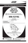
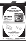
KIT FEATURES
A
B
C
D
A) Strip wire ends back ½"
B) Twist ends together
C) Solder
D) Tape
Right Front + ...............Gray
Right Front - ................Gray/Black
Left Front + ..................White
Left Front - ...................White/Black
Right Rear + .................Violet
Right Rear - ..................Violet/Black
Left Rear + ...................Green
Left Rear - ....................Green/Black
12 Volt Power................Red
Memory..........................Yellow
Ground..........................Black
Power Antenna.............Blue
Dimmer..........................Orange/White
Amp Turn-On................Blue/White
NOTE: Ground head unit to vehicle
Locate the factory wiring harness in the
dash. Metra recommends making
connections as shown using the
supplied wire harness. (Isolate and
individually tape off the ends of any
unused wires to prevent electrical short
circuit).
Shaft and
DIN unit
provisions
Various
mounting depth
alternatives
Incorporates
factory climate
controls into
installation
KIT COMPONENTS
Integrated
Mounting Kit
7
99-5720
INSTALLATION
INSTRUCTIONS
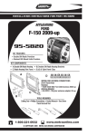
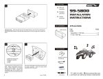
APPLICATIONS
CAR
PAGE
FORD
Escort 1997-04
Escort ZX2 1998-04
ZX2 2003-04*......................................1-3
MERCURY
Tracer 1997-99..................................1-3
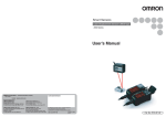
Speaker
Harness
Fig. B
* Note: Metra’s 70-5720 must be used on 2003-04 Zx2 and Escort Models
TOOLS REQUIRED
86-5618 - Head unit
removal keys
DIN HEAD UNITS: Slide the DIN cage into the Integrated Mounting Kit and secure by bending
the metal locking tabs down.Slide the aftermarket head unit into the cage until secure. (see Fig. B)
Torx-head screwdriver
1-800-221-0932
3
Rev. 12-21-07
Cutting tool
www.metraonline.com
© COPYRIGHT 2001-07 METRA ELECTRONICS CORPORATION
3
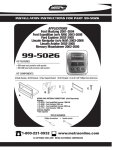
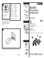
ALL VEHICLES
Fig. A
1
Fig. B
Fig. D
Fig. C
Disconnect the negative battery terminal to prevent an accidental short circuit. Reach under
the driver's side dash and unclip the temperature control cable. Using Metra's 86-5618, pull
the factory radio/climate control panel from the dash. Disconnect the switch power harness,
antenna plug, radio/speaker power harnesses and vacuum hose harness.
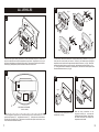
Turn the factory climate control dials into a vertical position and pull the dials off. (see Fig. A).
Unclip the vent control switch and remove. Remove (2) torx-head screws securing the
temperature control switch and fan speed control switch and remove. (see Fig. B). Mount the
switches to the back of the Integrated Mounting Kit with the same torx-head screws. (see Fig.
C). Holding the climate control dials in a vertical position, insert the dials onto the posts of the
mounted switches and secure. (see Fig. D)
2
4
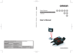
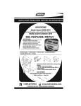
"C"
5
Fig. A
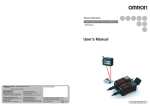
¾"
"A"
"B"
(BACK VIEW OF INTEGRATED
CONTROL PANEL)
Turn the integrated control panel over and disconnect the vent control harness ("A"), fan
speed control harness ("B"), and defroster harness ("C"). Unclip the main switch harness
from the side of the factory unit. (This harness connects the fan speed control harness, vent
control harness and defroster harness).
1
Cut and remove the shaded portion of the
sub-dash lip. (see Fig. A)
Make all wiring connections to the
and snap the
Integrated Mounting Kit
assembly into the sub-dash. Reach under
the driver's side dash and re-attach the
temperature control cable.
2